KR102514541B1 - Chopping type field emission x-ray driving device - Google Patents
Chopping type field emission x-ray driving deviceDownload PDFInfo
- Publication number
- KR102514541B1 KR102514541B1KR1020200127487AKR20200127487AKR102514541B1KR 102514541 B1KR102514541 B1KR 102514541B1KR 1020200127487 AKR1020200127487 AKR 1020200127487AKR 20200127487 AKR20200127487 AKR 20200127487AKR 102514541 B1KR102514541 B1KR 102514541B1
- Authority
- KR
- South Korea
- Prior art keywords
- voltage
- reference voltage
- voltage generator
- chopping
- ray
- Prior art date
- Legal status (The legal status is an assumption and is not a legal conclusion. Google has not performed a legal analysis and makes no representation as to the accuracy of the status listed.)
- Active
Links
- 238000012544monitoring processMethods0.000claimsabstractdescription30
- 238000000034methodMethods0.000claimsdescription18
- 238000009413insulationMethods0.000claimsdescription2
- 238000000465mouldingMethods0.000claimsdescription2
- OKTJSMMVPCPJKN-UHFFFAOYSA-NCarbonChemical compound[C]OKTJSMMVPCPJKN-UHFFFAOYSA-N0.000description9
- 239000002041carbon nanotubeSubstances0.000description9
- 229910021393carbon nanotubeInorganic materials0.000description9
- 238000010586diagramMethods0.000description7
- 230000000694effectsEffects0.000description7
- WFKWXMTUELFFGS-UHFFFAOYSA-NtungstenChemical compound[W]WFKWXMTUELFFGS-UHFFFAOYSA-N0.000description6
- 229910052721tungstenInorganic materials0.000description6
- 239000010937tungstenSubstances0.000description6
- 230000008859changeEffects0.000description4
- 230000008569processEffects0.000description4
- 230000005855radiationEffects0.000description4
- 230000002093peripheral effectEffects0.000description3
- 230000004075alterationEffects0.000description2
- 238000007796conventional methodMethods0.000description2
- 238000001816coolingMethods0.000description2
- 230000007423decreaseEffects0.000description2
- 238000013461designMethods0.000description2
- 238000005516engineering processMethods0.000description2
- 230000014509gene expressionEffects0.000description2
- 230000020169heat generationEffects0.000description2
- 238000010438heat treatmentMethods0.000description2
- 229910052751metalInorganic materials0.000description2
- 239000002184metalSubstances0.000description2
- 238000012986modificationMethods0.000description2
- 230000004048modificationEffects0.000description2
- 238000004846x-ray emissionMethods0.000description2
- 230000008901benefitEffects0.000description1
- 239000003990capacitorSubstances0.000description1
- 230000005684electric fieldEffects0.000description1
- 230000005611electricityEffects0.000description1
- 238000005265energy consumptionMethods0.000description1
- 238000002474experimental methodMethods0.000description1
- 238000003384imaging methodMethods0.000description1
- 238000004519manufacturing processMethods0.000description1
- 239000002086nanomaterialSubstances0.000description1
- 239000011347resinSubstances0.000description1
- 229920005989resinPolymers0.000description1
- 238000002834transmittanceMethods0.000description1
- 238000004804windingMethods0.000description1
Images


Classifications
- H—ELECTRICITY
- H05—ELECTRIC TECHNIQUES NOT OTHERWISE PROVIDED FOR
- H05G—X-RAY TECHNIQUE
- H05G1/00—X-ray apparatus involving X-ray tubes; Circuits therefor
- H05G1/08—Electrical details
- H05G1/26—Measuring, controlling or protecting
- H05G1/30—Controlling
- H05G1/32—Supply voltage of the X-ray apparatus or tube
- H—ELECTRICITY
- H01—ELECTRIC ELEMENTS
- H01J—ELECTRIC DISCHARGE TUBES OR DISCHARGE LAMPS
- H01J35/00—X-ray tubes
- H01J35/02—Details
- H01J35/025—X-ray tubes with structurally associated circuit elements
- H—ELECTRICITY
- H05—ELECTRIC TECHNIQUES NOT OTHERWISE PROVIDED FOR
- H05G—X-RAY TECHNIQUE
- H05G1/00—X-ray apparatus involving X-ray tubes; Circuits therefor
- H05G1/02—Constructional details
- H05G1/04—Mounting the X-ray tube within a closed housing
- H05G1/06—X-ray tube and at least part of the power supply apparatus being mounted within the same housing
- H—ELECTRICITY
- H05—ELECTRIC TECHNIQUES NOT OTHERWISE PROVIDED FOR
- H05G—X-RAY TECHNIQUE
- H05G1/00—X-ray apparatus involving X-ray tubes; Circuits therefor
- H05G1/08—Electrical details
- H05G1/26—Measuring, controlling or protecting
- H05G1/30—Controlling
- H05G1/46—Combined control of different quantities, e.g. exposure time as well as voltage or current
Landscapes
- Health & Medical Sciences (AREA)
- General Health & Medical Sciences (AREA)
- Toxicology (AREA)
- X-Ray Techniques (AREA)
Abstract
Translated fromKoreanDescription
Translated fromKorean본 발명은 초핑방식 전계 방출 엑스선 구동 장치에 관한 것으로서, 더욱 상세하게는 CNT Tube를 이용한 X-Ray 노출 시 대상체에게 불필요한 방사선 노출을 최소화 하기 위해, 기준전압 발생, 중간전압 체배, 트랜스포머를 이용한 고전압 체배 및 출력 고전압의 모니터링을 이용한 펄스 제어를 통한 초핑방식 전계 방출 엑스선 구동 장치에 관한 것이다.The present invention relates to a chopping-type field emission X-ray drive device, and more particularly, to minimize unnecessary radiation exposure to an object during X-Ray exposure using a CNT tube, a reference voltage is generated, a medium voltage is multiplied, and a high voltage is multiplied using a transformer. and a chopping-type field emission X-ray driving device through pulse control using monitoring of output high voltage.
X-Ray는 빠른 속도로 진행하는 전자가 금속 원자의 영향으로 급속하게 감속되거나 정지하는 경우 원래의 전자가 가지고 있던 운동 에너지가 전자기파의 형태로 변환된다. 특히 이러한 전자기파에서 진공 중에서 10-8~10-11m의 파장대를 갖고 있는 전자기파를 X-Ray라고 정의한다.In X-Ray, when electrons traveling at high speed rapidly decelerate or stop under the influence of metal atoms, the kinetic energy of the original electrons is converted into electromagnetic waves. In particular, among these electromagnetic waves, electromagnetic waves having a wavelength range of 10-8 to 10-11 m in a vacuum are defined as X-Ray.
일반적으로 X-Ray를 발생시키기 위해서는 열음극 방식의 X-Ray 소스를 사용하며, 일반적으로 텅스텐으로 만들어진 필라멘트에 전압을 가하면 필라멘트에 전류가 흐르면서 가열되며, 이와 함께 필라멘트를 음극(Cathode)으로 하고 금속판을 양극(Anode)로 하여 수kV~수십kV의 전압을 인가한다. 이때 가열된 필라멘트 음극에서 에너지를 얻은 열전자가 방출되는데, 방출된 전자는 고전압에 따라 가속되며, 가속된 전자는 양극 전극인 금속판에 충돌하는 이때 전자가 가지고 있던 운동에너지가 전자기 에너지와 열에너지로 변환된다. 이때 전자의 운동에너지가 전자기 에너지로 변환된 것이 X-Ray로 나타나게 된다.In general, to generate X-Ray, a hot cathode type X-Ray source is used. Generally, when a voltage is applied to a filament made of tungsten, current flows through the filament and heats it. A voltage of several kV to several tens of kV is applied as an anode. At this time, thermal electrons obtained with energy from the heated filament cathode are emitted. The emitted electrons are accelerated according to the high voltage, and the accelerated electrons collide with the metal plate, which is the anode electrode, and the kinetic energy of the electrons is converted into electromagnetic energy and thermal energy. . At this time, the kinetic energy of electrons is converted into electromagnetic energy and appears as X-Ray.
텅스텐 필라멘트 기반의 열음극 X-Ray 장치는 전자를 발생시키는 데에 많은 전력이 소모되며, 발생되는 전자가 스파이럴 구조를 갖는 텅스텐 표면에서 무작위로 방출되기 때문에 Heel effect에 의한 색수차가 불가피하게 발생되며, 이는 X-Ray 방출시 X-Ray 선질을 크게 감소시키는 한계를 가진다.Tungsten filament-based hot cathode X-Ray devices consume a lot of power to generate electrons, and since the generated electrons are randomly emitted from the tungsten surface having a spiral structure, chromatic aberration due to the Heel effect inevitably occurs. When X-Ray is emitted, it has a limit to greatly reduce the quality of X-Ray.
또한 텅스텐 필라멘트의 가열 및 냉각을 위해 일정 시간의 인터벌(interval)이 요구되며, 펄스형태로 X-Ray을 방출시키는 것이 어려워 필요 이상의 다량의 X-Ray를 환자에게 노출되는 문제가 있다.In addition, an interval of a certain time is required for heating and cooling the tungsten filament, and it is difficult to emit X-rays in the form of pulses, so there is a problem in that a large amount of X-rays is exposed to the patient.
현재 의료기에서 사용되고 있는 텅스텐 필라멘트 기반의 열음극 X-Ray 장치는 일반적으로 0.01 ~ 수초간 X-Ray를 연속으로 출력하고, 이를 다양한 디텍터를 통해 인체 내부 구조를 검출하고 있다.Tungsten filament-based hot cathode X-ray devices currently used in medical devices continuously output X-rays for 0.01 to several seconds, and detect the internal structure of the human body through various detectors.
그러나 이러한 단계에서 텅스텐 필라멘트 기반의 열음극 X-Ray 장치의 경우, 장치의 구조 특성상 가열 및 냉각 시간과 함께, 환자에게 불필요한 방사선이 발생하여 노출되는 문제가 있다.However, in the case of a hot cathode X-ray device based on a tungsten filament in this step, there is a problem in that unnecessary radiation is generated and exposed to the patient along with heating and cooling time due to the structural characteristics of the device.
기존의 열음극 X-Ray 소스 장치의 문제점을 해결하기 위해 최근에는 냉음극 전자 방출원으로 탄소나노튜브(CNT) 등 나노 구조물을 이용한 전계 방출(field emission) X-Ray 기술이 개발되고 있으며, 기존의 아날로그 열전자 방출 방식과 달리, 추가적인 열에너지 인가를 위한 전력이 필요 없고 단지 전압(전기장)의 인가만으로 전자 방출이 가능하며, 방출되는 전자가 탄소나노튜브의 길이 방향을 따라 진행하기 때문에 애노드 전극 측의 타켓을 향한 전자의 방향 지향성이 우수하여 색수차가 극히 적은 엑스선 방출 선질과 효율도 매우 높은 장점을 갖고 있다.In order to solve the problems of the existing hot cathode X-Ray source device, field emission X-Ray technology using nanostructures such as carbon nanotubes (CNT) has been recently developed as a cold cathode electron emission source. Unlike the analog thermionic emission method, no power is required to apply additional thermal energy, and electron emission is possible only by applying a voltage (electric field). Since the emitted electrons proceed along the length direction of the carbon nanotube, the target It has the advantage of very high efficiency and X-ray emission quality with extremely low chromatic aberration due to excellent directivity of electrons toward the .
그러나, 이러한 전계 방출 X-Ray 기술에 사용되는 CNT 튜브 역시 지속적으로 전원이 공급되면 열이 발생되는 문제가 있다.However, the CNT tube used in the field emission X-ray technology also has a problem in that heat is generated when power is continuously supplied.
한국공개특허 [10-2017-0032718]에서는 전계 방출 엑스선 소스 장치가 개시되어 있다.Korean Patent Publication [10-2017-0032718] discloses a field emission X-ray source device.
따라서, 본 발명은 상기한 바와 같은 문제점을 해결하기 위하여 안출된 것으로, 본 발명의 목적은 CNT Tube를 이용한 X-Ray 노출 시 대상체에게 불필요한 방사선 노출을 최소화 하기 위해, 기준전압 발생, 중간전압 체배, 트랜스포머를 이용한 고전압 체배 및 출력 고전압의 모니터링을 이용한 펄스 제어를 통한 초핑방식 전계 방출 엑스선 구동 장치를 제공하는 것이다.Therefore, the present invention has been devised to solve the above problems, and an object of the present invention is to minimize unnecessary radiation exposure to an object during X-Ray exposure using a CNT tube, generating a reference voltage, multiplying a medium voltage, An object of the present invention is to provide a chopping-type field emission X-ray driving device through pulse control using high voltage multiplication using a transformer and monitoring of an output high voltage.
본 발명의 실 시예들의 목적은 이상에서 언급한 목적으로 제한되지 않으며, 언급되지 않은 또 다른 목적들은 아래의 기재로부터 본 발명이 속하는 기술분야에서 통상의 지식을 가진 자에게 명확하게 이해될 수 있을 것이다.Objects of the embodiments of the present invention are not limited to the above-mentioned purposes, and other objects not mentioned above will be clearly understood by those skilled in the art from the description below. .
상기한 바와 같은 목적을 달성하기 위한 본 발명의 일 실시예에 따른 초핑방식 전계 방출 엑스선 구동 장치는, 냉음극 측의 전자방출원으로부터 방출되어 가속된 전자를 애노드 전극 측의 타겟에 충돌시켜 엑스선을 방출하는 디지털엑스레이튜브(10); 재충전 가능하며 전원을 공급하는 전원부(100); 상기 전원부(100)로부터 전원을 공급 받아 고전압 발생을 위한 기 설정된 기준전압으로 전압을 조정하는 기준전압발생부(200); 상기 기준전압발생부(200)로부터 전원을 공급받아 기 설정된 중간전압으로 전압을 승압시키는 중간전압발생부(300); 상기 기준전압발생부(200)로부터 전원을 공급받아 상기 디지털엑스레이튜브(10)를 구동하기 위한 고전압으로 전압을 승압시키는 구동전압발생부(400); 상기 디지털엑스레이튜브(10)에 인가된 전압 및 전류를 모니터링하는 모니터링부(500); 상기 기준전압발생부(200)의 출력 전압을 제어하며, 상기 모니터링부(500)가 모니터링한 전압 및 전류를 기반으로 상기 기준전압발생부(200)의 출력 전압을 피드백 제어하는 기준전압제어부(600); 및 상기 기준전압발생부(200)가 주기적으로 출력 전압을 출력하는 초핑 방식으로 출력 전압이 출력되도록 상기 기준전압제어부(600)에 초핑신호를 주는 초핑제어부(900); 를 포함하는 것을 특징으로 한다.In order to achieve the above object, a chopping-type field emission X-ray driver according to an embodiment of the present invention collides accelerated electrons emitted from an electron emission source on a cold cathode side with a target on the anode electrode side to generate X-rays.
또한, 상기 중간전압발생부(300)는 Cockcroft-Walton 회로로 구성되는 것을 특징으로 한다.In addition, the
또, 상기 초핑방식 전계 방출 엑스선 구동 장치는, 상기 전원부(100)로부터 전원을 공급받아 상기 기준전압제어부(600)의 구동에 필요한 전원을 공급하는 제어전원공급부(700);를 포함하는 것을 특징으로 한다.In addition, the chopping type field emission X-ray driving device includes a control
또한, 상기 제어전원공급부(700)는 LDO(Low Dropout)를 사용하는 것을 특징으로 한다.In addition, the control
아울러, 상기 디지털엑스레이튜브(10), 기준전압발생부(200), 중간전압발생부(300), 구동전압발생부(400), 모니터링부(500), 기준전압제어부(600)는 절연 몰딩하여 사용하는 것을 특징으로 한다.In addition, the
본 발명의 일 실시예에 따른 초핑방식 전계 방출 엑스선 구동 장치에 의하면, 디지털엑스레이튜브에 공급되는 전원을 초핑 시킴으로써, 엑스선 방출 선질을 보다 향상시키고, 디지털엑스레이튜브 및 주변 기기의 수명을 보다 증가시킬 수 있는 효과가 있다.According to the chopping-type field emission X-ray driving device according to an embodiment of the present invention, by chopping the power supplied to the digital X-ray tube, the quality of the X-ray emission can be further improved and the lifetime of the digital X-ray tube and peripheral devices can be further increased. There is an effect.
또한, Cockcroft-Walton 회로로 중간전압발생부를 구성함으로써, 변압기를 사용하는 것 보다 부피와 무게를 줄이면서 중간전압으로의 승압이 가능한 효과가 있다.In addition, by configuring the intermediate voltage generator with the Cockcroft-Walton circuit, there is an effect of enabling step-up to the intermediate voltage while reducing the volume and weight compared to using a transformer.
또, LDO를 사용한 제어전원공급부를 별도로 구비함으로써, 기준전압제어부가 전원부 보다 낮은 전압에서 동작하도록 함으로써, 기준전압제어부의 에너지 사용량을 줄이고, 기준전압제어부의 발열을 줄이는 효과가 있다.In addition, by separately providing a control power supply unit using an LDO, the reference voltage control unit operates at a lower voltage than the power supply unit, thereby reducing energy consumption of the reference voltage control unit and heat generation of the reference voltage control unit.
또한, 외부에 노출되면 고전압 방전이 발생될 위험이 있는 구성을 절연 몰딩하여 사용함으로써, 고전압 방전 발생 위험을 줄일 수 있는 효과가 있다.In addition, there is an effect of reducing the risk of high voltage discharge by insulating and using a configuration in which there is a risk of high voltage discharge when exposed to the outside.
또한, μsec급의 고속 제어가 가능한 펄스형태의 엑스선을 방출시키는 것이 용이하여 낮은 방사선량으로 엑스선 영상 획득이 가능한 효과가 있다.In addition, since it is easy to emit pulse-type X-rays capable of high-speed control of the μsec level, an X-ray image can be obtained with a low radiation dose.
또, 환자에게 필요한 최적으로 노출 시간을 디지털 방식으로 제어하여 최소의 방사선으로 엑스선 영상 검출이 가능한 효과가 있다.In addition, there is an effect of detecting an X-ray image with minimal radiation by digitally controlling the optimal exposure time required by the patient.
또한, 본 장치를 통해 1ms~500ms 수준의 초핑 방식으로 디지털엑스레이튜브를 동작할 경우 대상자에게 필요한 최소 방사선 노출로 피폭량을 대폭 감소할 수 있으며, 이를 통해 인체 피폭량을 낮추고, 방사선으로 인한 위험성을 낮출수 있는 효과가 있다.In addition, when the digital X-ray tube is operated in a chopping method of 1 ms to 500 ms through this device, the amount of exposure can be greatly reduced with the minimum radiation exposure required for the subject, thereby reducing the amount of human exposure and the risk due to radiation. There is an effect.
아울러, 기준전압에서 중간전압으로, 중간전압에서 고전압으로 2 단계 승압 과정을 거치도록 함으로써, 초핑동작으로 고전압 체배회로에 의해 발생할 수 있는 과전압을 방지하고, 이와 함께 과전류 발생으로 인한 배터리 손상 방지 및 수명 연장이 가능하며. 노출 가능 횟수 또한 증가시키는 효과가 있다.In addition, by going through a two-step step-up process from the reference voltage to the medium voltage and from the medium voltage to the high voltage, the chopping operation prevents overvoltage that may occur due to the high voltage multiplier circuit, and at the same time, battery damage due to overcurrent occurs, and Life extension is possible. It also has the effect of increasing the number of possible exposures.
도 1은 본 발명의 일 실시예에 따른 초핑방식 전계 방출 엑스선 구동 장치의 개념도.
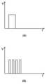
도 2는 종래에 디지털엑스레이튜브에 전원을 공급하는 방식을 보여주는 예시도(A) 및 본 발명의 일 실시예에 따른 초핑방식 전계 방출 엑스선 구동 장치로 디지털엑스레이튜브에 전원을 공급하는 방식을 보여주는 예시도(B).
도 3은 본 발명의 다른 실시예에 따른 초핑방식 전계 방출 엑스선 구동 장치의 개념도.
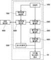
도 4는 기준전압발생부(200), 중간전압발생부(300), 구동전압발생부(400), 모니터링부(500) 및 기준전압제어부(600)가 하나의 보드(Board)로 구현되고, 해당 보드와 디지털엑스레이튜브(10)가 절연 몰딩 된 것을 보여주는 예시도.
도 5는 전원부(100), 기준전압발생부(200), 중간전압발생부(300), 구동전압발생부(400), 모니터링부(500) 및 기준전압제어부(600)가 하나의 보드(Board)로 구현되고, 해당 보드와 디지털엑스레이튜브(10)가 절연 몰딩 된 것을 보여주는 예시도.1 is a conceptual diagram of a chopping-type field emission X-ray driving device according to an embodiment of the present invention.
2 is an exemplary diagram (A) showing a conventional method of supplying power to a digital X-ray tube and an example of a method of supplying power to a digital X-ray tube with a chopping-type field emission X-ray driving device according to an embodiment of the present invention. Figure (B).
3 is a conceptual diagram of a chopping-type field emission X-ray driving device according to another embodiment of the present invention.
4 shows that the
5 is a
본 발명은 다양한 변경을 가할 수 있고 여러 가지 실시예를 가질 수 있는바, 특정 실시예들을 도면에 예시하고 상세하게 설명하고자 한다. 그러나 이는 본 발명을 특정한 실시 형태에 대해 한정하려는 것이 아니며, 본 발명의 사상 및 기술 범위에 포함되는 모든 변경, 균등물 내지 대체물을 포함하는 것으로 이해되어야한다.Since the present invention can make various changes and have various embodiments, specific embodiments will be illustrated in the drawings and described in detail. However, this is not intended to limit the present invention to specific embodiments, and should be understood to include all modifications, equivalents, or substitutes included in the spirit and scope of the present invention.
어떤 구성요소가 다른 구성요소에 "연결되어" 있다거나 "접속되어" 있다고 언급된 때에는, 그 다른 구성요소에 직접적으로 연결되어 있거나 또는 접속되어 있을 수도 있지만, 중간에 다른 구성요소가 존재할 수도 있다고 이해되어야 할 것이다.It is understood that when an element is referred to as being "connected" or "connected" to another element, it may be directly connected or connected to the other element, but other elements may exist in the middle. It should be.
반면에, 어떤 구성요소가 다른 구성요소에 "직접 연결되어" 있다거나 "직접 접속되어" 있다고 언급된 때에는, 중간에 다른 구성요소가 존재하지 않는 것으로 이해되어야 할 것이다.On the other hand, when an element is referred to as “directly connected” or “directly connected” to another element, it should be understood that no other element exists in the middle.
본 명세서에서 사용되는 용어는 단지 특정한 실시예를 설명하기 위해 사용된 것으로, 본 발명을 한정하려는 의도가 아니다. 단수의 표현은 문맥상 명백하게 다르게 뜻하지 않는 한, 복수의 표현을 포함한다. 본 출원에서, "포함하다" 또는 "가지다" 등의 용어는 명세서상에 기재된 특징, 숫자, 공정, 동작, 구성요소, 부품 또는 이들을 조합한 것이 존재함을 지정하려는 것이지, 하나 또는 그 이상의 다른 특징들이나 숫자, 공정, 동작, 구성요소, 부품 또는 이들을 조합한 것들의 존재 또는 부가 가능성을 미리 배제하지 않는 것으로 이해되어야 한다.Terms used in this specification are only used to describe specific embodiments, and are not intended to limit the present invention. Singular expressions include plural expressions unless the context clearly dictates otherwise. In this application, the terms "include" or "have" are intended to designate that there is a feature, number, process, operation, component, part, or combination thereof described in the specification, but one or more other features It should be understood that the presence or addition of numbers, processes, operations, components, parts, or combinations thereof is not precluded.
다르게 정의되지 않는 한, 기술적이거나 과학적인 용어를 포함해서 여기서 사용되는 모든 용어들은 본 발명이 속하는 기술 분야에서 통상의 지식을 가진 자에 의해 일반적으로 이해되는 것과 동일한 의미가 있다. 일반적으로 사용되는 사전에 정의되어 있는 것과 같은 용어들은 관련 기술의 문맥상 가지는 의미와 일치하는 의미가 있는 것으로 해석되어야 하며, 본 출원에서 명백하게 정의하지 않는 한, 이상적이거나 과도하게 형식적인 의미로 해석되지 않는다.Unless defined otherwise, all terms used herein, including technical or scientific terms, have the same meaning as commonly understood by one of ordinary skill in the art to which the present invention belongs. Terms such as those defined in commonly used dictionaries should be interpreted as having meanings consistent with the meanings in the context of the related art, and unless explicitly defined in this application, they should not be interpreted in ideal or excessively formal meanings. don't
이하, 첨부된 도면을 참조하여 본 발명을 더욱 상세하게 설명한다. 이에 앞서, 본 명세서 및 청구범위에 사용된 용어나 단어는 통상적이거나 사전적인 의미로 한정하여 해석되어서는 아니 되며, 발명자는 그 자신의 발명을 가장 최선의 방법으로 설명하기 위해 용어의 개념을 적절하게 정의할 수 있다는 원칙에 입각하여, 본 발명의 기술적 사상에 부합하는 의미와 개념으로 해석되어야만 한다. 또한, 사용되는 기술 용어 및 과학 용어에 있어서 다른 정의가 없다면, 이 발명이 속하는 기술분야에서 통상의 지식을 가진 자가 통상적으로 이해하고 있는 의미를 가지며, 하기의 설명 및 첨부 도면에서 본 발명의 요지를 불필요하게 흐릴 수 있는 공지 기능 및 구성에 대한 설명은 생략한다. 다음에 소개되는 도면들은 당업자에게 본 발명의 사상이 충분히 전달될 수 있도록 하기 위해 예로서 제공되는 것이다. 따라서, 본 발명은 이하 제시되는 도면들에 한정되지 않고 다른 형태로 구체화될 수도 있다. 또한, 명세서 전반에 걸쳐서 동일한 참조번호들은 동일한 구성요소들을 나타낸다. 도면들 중 동일한 구성요소들은 가능한 한 어느 곳에서든지 동일한 부호들로 나타내고 있음에 유의해야 한다.Hereinafter, the present invention will be described in more detail with reference to the accompanying drawings. Prior to this, the terms or words used in this specification and claims should not be construed as being limited to ordinary or dictionary meanings, and the inventor appropriately uses the concept of terms in order to explain his/her invention in the best way. Based on the principle that it can be defined, it should be interpreted as meaning and concept consistent with the technical spirit of the present invention. In addition, unless there is another definition in the technical terms and scientific terms used, they have meanings commonly understood by those of ordinary skill in the art to which this invention belongs, and the gist of the present invention is described in the following description and accompanying drawings. Descriptions of well-known functions and configurations that may be unnecessarily obscure are omitted. The drawings introduced below are provided as examples to sufficiently convey the spirit of the present invention to those skilled in the art. Accordingly, the present invention may be embodied in other forms without being limited to the drawings presented below. Also, like reference numerals denote like elements throughout the specification. It should be noted that like elements in the drawings are indicated by like numerals wherever possible.
도 1은 본 발명의 일 실시예에 따른 초핑방식 전계 방출 엑스선 구동 장치의 개념도이고, 도 2는 종래에 디지털엑스레이튜브에 전원을 공급하는 방식을 보여주는 예시도(A) 및 본 발명의 일 실시예에 따른 초핑방식 전계 방출 엑스선 구동 장치로 디지털엑스레이튜브에 전원을 공급하는 방식을 보여주는 예시도(B)이며, 도 3은 본 발명의 다른 실시예에 따른 초핑방식 전계 방출 엑스선 구동 장치의 개념도이고, 도 4는 기준전압발생부(200), 중간전압발생부(300), 구동전압발생부(400), 모니터링부(500) 및 기준전압제어부(600)가 하나의 보드(Board)로 구현되고, 해당 보드와 디지털엑스레이튜브(10)가 절연 몰딩 된 것을 보여주는 예시도이며, 도 5는 전원부(100), 기준전압발생부(200), 중간전압발생부(300), 구동전압발생부(400), 모니터링부(500) 및 기준전압제어부(600)가 하나의 보드(Board)로 구현되고, 해당 보드와 디지털엑스레이튜브(10)가 절연 몰딩 된 것을 보여주는 예시도이다.1 is a conceptual diagram of a chopping-type field emission X-ray driving device according to an embodiment of the present invention, and FIG. 2 is an exemplary diagram (A) showing a conventional method of supplying power to a digital X-ray tube and an embodiment of the present invention. It is an exemplary diagram (B) showing a method of supplying power to a digital X-ray tube with a chopping-type field emission X-ray drive device according to, FIG. 3 is a conceptual diagram of a chopping-type field emission X-ray drive device according to another embodiment of the present invention, 4 shows that the
도 1에 도시된 바와 같이, 본 발명의 일 실시예에 따른 초핑방식 전계 방출 엑스선 구동 장치는 디지털엑스레이튜브(10), 전원부(100), 기준전압발생부(200), 중간전압발생부(300), 구동전압발생부(400), 모니터링부(500), 기준전압제어부(600) 및 초핑제어부(900)를 포함한다.As shown in FIG. 1, the chopping method field emission X-ray driving device according to an embodiment of the present invention includes a
디지털엑스레이튜브(10)는 냉음극 측의 전자방출원으로부터 방출되어 가속된 전자를 애노드 전극 측의 타겟에 충돌시켜 엑스선을 방출한다.The
상기 디지털엑스레이튜브(10)로는 탄소나노튜브(CNT; Carbon Nano Tube) 기반 디지털 엑스선 소스를 사용할 수 있으며, 탄소나노튜브를 전자방출원으로 활용해서 엑스선을 방출한다.A carbon nano tube (CNT)-based digital X-ray source may be used as the
전원부(100)는 재충전 가능하며 전원을 공급한다.The
상기 전원부(100)는 본 발명의 일 실시예에 따른 초핑방식 전계 방출 엑스선 구동 장치에 전원을 공급하기 위한 구성으로, 재충전이 가능하다. 즉 일반적인 이차전지를 사용할 수 있다.The
상기 전원부(100)는 초핑제어부(900)에서 발생하는 제어신호에 따라 펄스(Pulse) 형태의 고전압을 발생시켜 초핑 방식으로 X-Ray를 구동하기 위하여, 방전률 10 C 이상의 고방전이 가능한 재충전 가능한 배터리를 전원부(100)로 사용하는 것이 바람직하다.The
방전율(Discharge Ratio)은 사용한 전류(A)를 축전지 용량(Ah)으로 나눈 값을 말하는 것으로, 전지의 정격용량을 사용 완료하는 속도를 의미한다.The discharge rate (Discharge Ratio) refers to a value obtained by dividing the current (A) used by the battery capacity (Ah), and means the speed at which the rated capacity of the battery is completed.
방전율이 높다는 것은 대전류로 빠르게 사용 완료하는 것을 의미한다.A high discharge rate means rapid completion of use with a large current.
실용적으로는 전지의 정격용량 [단위 Ah(암페어시)]을 1시간 동안에 사용 완료하는 방전율을 1 C 방전이라 하며, 10시간에 사용 완료하면 0.1 C 방전이라 한다.In practical terms, the discharge rate at which the battery's rated capacity [unit Ah (ampere hour)] is used for 1 hour is called 1 C discharge, and when it is used for 10 hours, it is called 0.1 C discharge.
기준전압발생부(200)는 상기 전원부(100)로부터 전원을 공급 받아 고전압 발생을 위한 기 설정된 기준전압으로 전압을 조정한다.The
상기 기준전압발생부(200)는 상기 전원부(100)와 연결되어, 상기 전원부(100)의 전압을 입력받아 기 설정된 기준전압으로 전압을 조정한다.The
상기 전원부(100)의 전원을 그대로 이용하는 경우, 미세한 전압 변화에도 상기 디지털엑스레이튜브(10)에 공급되는 고전압은 크게 변할 수 있다.When the power of the
예를 들어, 상기 전원부(100)의 전압이 1%만 변해도 수백 볼트 이상의 전압 변화가 발생될 수 있다.For example, even if the voltage of the
따라서, 이러한 전압변화가 0.01% 이내가 되도록 하는 것이 바람직하며, 이를 상기 기준전압발생부(200)에서 처리해준다.Therefore, it is desirable to make this voltage change within 0.01%, and the
상기 기준전압발생부(200)는 상기 전원부(100)가 출력한다고 명시된 출력 전압 보다 낮은 전압을 출력하도록 하는 것도 가능하고, 같은 전압을 출력하도록 하는 것도 가능하며, 높은 전압을 출력하도록 하는 것도 가능하다.The reference
예를 들어, 상기 전원부(100)가 12V 배터리라고 한다면, 상기 기준전압발생부(200)는 10V, 12V, 14V 등으로 출력되도록 할 수 있다.For example, if the
상기 전원부(100)의 전압을 그대로 사용할 경우, 일반적인 배터리는 전기를 사용할수록 출력 전압이 낮아지거나, 온도 등 주변 환경 변화에 따라 여러 가지 이유로 출력 전압에 변화가 발생될 수 있기 때문에, 상기 기준전압발생부(200)에서 기준전압이 일정하게 유지될 수 있도록 조정해 주는 것이 바람직하다.When the voltage of the
중간전압발생부(300)는 상기 기준전압발생부(200)로부터 전원을 공급받아 기 설정된 중간전압으로 전압을 승압시킨다.The
상기 기준전압발생부(200)에서 출력되는 기준전압을 바로 상기 디지털엑스레이튜브(10)에 공급되는 고전압으로 승압시키기 위해서는 고배율 변압기가 필요하나, 고배율 변압기는 권선비로 인해 부피가 커져 포터블 형으로 제작하기 어려운 문제가 있다.In order to step up the reference voltage output from the
이러한 문제를 해결하기 위해 상기 중간전압발생부(300)를 구비하며, 상기 중간전압발생부(300)는 상기 기준전압발생부(200)에서 출력되는 기준전압을 일정 배수로 체배(遞倍)하여, 고배율 변압기는 권선비로 인해 부피가 커지지 않도록 하는 것이 바람직하다.To solve this problem, the
구동전압발생부(400)는 상기 기준전압발생부(200)로부터 전원을 공급받아 상기 디지털엑스레이튜브(10)를 구동하기 위한 고전압으로 전압을 승압시킨다.The driving
이때, 상기 구동전압발생부(400)는 상기 디지털엑스레이튜브(10)에 전압을 인가하여 상기 디지털엑스레이튜브(10)로 전류가 흐르도록 한다.At this time, the driving
상기 구동전압발생부(400)는 상기 중간전압발생부(300)로부터 체배된 중간전압을 상기 디지털엑스레이튜브(10)에 공급되는 고전압으로 승압하기 위하여, 고전압 트랜스포머를 사용하여, 중간전압을 고전압으로 승압시킬 수 있다.The driving
예를 들어, 50kV~100kV의 전압 및 0.5~2.5mA의 전류를 디지털엑스레이튜브(10)에 입력하여 엑스선이 방출되도록 할 수 있다.For example, X-rays may be emitted by inputting a voltage of 50 kV to 100 kV and a current of 0.5 to 2.5 mA to the
즉, 본 발명의 일 실시예에 따른 초핑방식 전계 방출 엑스선 구동 장치는 상기 기준전압발생부(200), 상기 중간전압발생부(300) 및 상기 구동전압발생부(400)를 순차적으로 거치면서, 상기 디지털엑스레이튜브(10)에 공급되는 고전압을 발생시킨다.That is, the chopping-type field emission X-ray driving device according to an embodiment of the present invention sequentially passes through the
모니터링부(500)는 상기 디지털엑스레이튜브(10)에 인가된 전압 및 전류를 모니터링한다.The
상기 모니터링부(500)는 상기 디지털엑스레이튜브(10)에 사용되는 전압 및 전류를 측정하여 그 결과를 기준전압제어부(600)에 전달한다.The
기준전압제어부(600)는 상기 기준전압발생부(200)의 출력 전압을 제어하며, 상기 모니터링부(500)가 모니터링한 전압 및 전류를 기반으로 상기 기준전압발생부(200)의 출력 전압을 피드백 제어한다.The
상기 기준전압제어부(600)로는 마이크로컨트롤러(MCU; Micro Controller Unit)를 사용할 수 있으며, 기 설정된 초핑 주기와 기준전압을 근거로 상기 기준전압발생부(200)의 출력 전압을 제어하되, 상기 모니터링부(500)가 측정한 전압 및 전류를 기반으로 상기 기준전압발생부(200)의 출력 전압을 피드백 제어할 수 있다.A microcontroller (MCU) may be used as the reference
예를 들어, 피드백 제어는 고전압 정확도 0.001% 이내가 되도록 제어할 수 있다. 이는 사용자에게 최소의 방사선 노출이 가능하도록 하기 위한 실험에 의해 도출된 수치이다.For example, feedback control can be controlled to be within 0.001% of high voltage accuracy. This is a numerical value derived by an experiment to enable the minimum radiation exposure to the user.
상기 기준전압제어부(600)는 초핑 주기와 기준전압을 외부로부터 입력받을 수 있다.The
초핑제어부(900)는 상기 기준전압발생부(200)가 주기적으로 출력 전압을 출력하는 초핑 방식으로 출력 전압이 출력되도록 상기 기준전압제어부(600)에 초핑신호를 준다.The chopping
상기 초핑제어부(900)는 초핑제어에 필요한 초핑 주기와 기준전압 등의 정보를 포함하는 초핑신호를 상기 기준전압제어부(600)에 전달한다.The chopping
상기 초핑제어부(900)로부터 초핑신호를 전달받은 상기 기준전압제어부(600)는 전달 받은 초핑신호에 의해 기준전압을 초핑 방식으로 출력한다.The reference
예를 들어, 상기 초핑제어부(900)가 상기 기준전압제어부(600)에 출력 주기 1ms~500ms의 기준전압이 발생되도록 초핑신호를 전달한다면, 상기 디지털엑스레이튜브(10)에 공급되는 고전압도 출력 주기 1ms~500ms의 고전압이 발생되도록 할 수 있다.For example, if the chopping
즉, 기준전압의 초핑으로 상기 디지털엑스레이튜브(10)에 공급되는 고전압도 초핑이 되며, 이로 인해 발생되는 엑스선 역시 초핑 형식으로 방출(도 2의 (B) 참조)된다.That is, by chopping the reference voltage, the high voltage supplied to the
다시 말해, μsec급의 고속 제어가 가능한 펄스형태의 엑스선을 방출시키는 것이 가능하다.In other words, it is possible to emit pulse-type X-rays capable of high-speed control of the μsec level.
이때, 기준전압제어부(600)는 모니터링부(500)로부터 측정된 전압 및 전류를 바탕으로 상기 기준전압발생부(200)를 피드백 제어를 하여, 상기 디지털엑스레이튜브(10)에 공급되는 전압 및 전류가 기 설정된 전압 및 전류에 가까워 지도록 제어하여, 원하는 정도의 선명한 엑스선 촬영 결과를 얻을 수 있음과 동시에, 사용자에게 최소의 방사선 노출이 가능하도록 할 수 있다.At this time, the reference
디지털엑스레이튜브(10)에 전원이 공급되면 디지털엑스레이튜브(10)에 열이 발생된다.When power is supplied to the
도 2의 상측에 도시된 (A)의 예시는 엑스선 영상을 얻기 위한 전압을 일정시간 디지털엑스레이튜브(10)에 공급한 것을 나타낸 예이며, 도 2의 하측에 도시된 (B)의 예시는 (A)의 일정시간을 4 등분 하여 초핑을 한 예이다.The example of (A) shown on the upper side of FIG. 2 is an example showing that a voltage for obtaining an X-ray image is supplied to the
엑스레이 촬영 영상의 품질은 디지털엑스레이튜브(10)에 공급되는 전압과 해당 전압의 유지 시간에 의해 결정될 수 있다.The quality of an X-ray photographed image may be determined by a voltage supplied to the
전압은 엑스선이 투과할 수 있는 투과율과 밀접한 관계가 있고, 전압의 유지 시간은 영상의 선명도와 밀접한 관계가 있다.The voltage is closely related to the transmittance through which X-rays can pass, and the holding time of the voltage is closely related to the sharpness of the image.
즉, 동일 전압을 동일 시간만큼 디지털엑스레이튜브(10)에 공급한다면, 이론적으로 동일 품질의 영상을 얻을 수 있다.That is, if the same voltage is supplied to the
그러나, 도 2의 상측에 도시된 (A)의 예시와 같이, 디지털엑스레이튜브(10)에 지속적으로 전원이 공급되면, 디지털엑스레이튜브(10)에 열이 발생되어, X-Ray 선질을 감소시키고, 디지털엑스레이튜브(10) 및 주변 기기의 수명을 단축시킬 수 있다.However, as in the example of (A) shown on the upper side of FIG. 2, when power is continuously supplied to the
이를 해결하기 위해, 도 2의 하측에 도시된 (B)의 예시와 같이, 디지털엑스레이튜브(10)에 공급되는 전원을 초핑 시키면, 전원이 공급되지 않는 기간동안 디지털엑스레이튜브(10)가 냉각되어, 디지털엑스레이튜브(10)의 열이 더 적게 발생되도록 할 수 있어, 선질을 보다 향상시키고, 디지털엑스레이튜브(10) 및 주변 기기의 수명을 보다 증가시킬 수 있다.In order to solve this problem, as in the example of (B) shown in the lower part of FIG. 2, when the power supplied to the
본 발명의 일 실시예에 따른 초핑방식 전계 방출 엑스선 구동 장치의 중간전압발생부(300)는 Cockcroft-Walton 회로로 구성되는 것을 특징으로 할 수 있다.The
Cockcroft-Walton 회로는 n 개의 콘덴서와 다이오드로 전압을 높이는 방식으로, 변압기를 사용하지 않고도 고승압이 가능하며, n배 전압 정류회로로 불리기도 한다.The Cockcroft-Walton circuit is a method of increasing the voltage with n condensers and diodes, and it is possible to increase the voltage without using a transformer, and is also called an n-fold voltage rectification circuit.
Cockcroft-Walton 회로는 각각의 반주기마다 콘덴서를 번갈아 충전하면서 전압을 높여가는 회로로, 높은 전압을 얻을 수는 있지만 단수가 늘어날수록 출력전류는 급격하게 낮아지기 때문에, 기준전압발생부(200)에서 발생된 기준전압은 최소 2배에서 최대 10배 이내로 체배하는 것이 바람직하다.The Cockcroft-Walton circuit is a circuit that increases the voltage while alternately charging the capacitor at each half cycle. Although a high voltage can be obtained, the output current rapidly decreases as the number of stages increases. It is desirable to multiply the reference voltage within a minimum of 2 times and a maximum of 10 times.
즉, 중간전압발생부(300)를 Cockcroft-Walton 회로로 구성함으로써, 변압기를 사용하지 않고도 변압기를 사용하는 것 보다 부피와 무게를 줄이면서 중간전압으로의 승압이 가능하다.That is, by configuring the
따라서, 엑스선 장치를 더욱 작고 가볍게 만들 수 있어, 포터블형 엑스선 장치에 더욱 적합하다.Accordingly, it is possible to make the X-ray device smaller and lighter, which is more suitable for a portable X-ray device.
도 3에 도시된 바와 같이, 본 발명의 일 실시예에 따른 초핑방식 전계 방출 엑스선 구동 장치는 상기 전원부(100)로부터 전원을 공급받아 상기 기준전압제어부(600)의 구동에 필요한 전원을 공급하는 제어전원공급부(700)를 포함할 수 있다.As shown in FIG. 3 , the chopping type field emission X-ray driving device according to an embodiment of the present invention receives power from the
상기 제어전원공급부(700)는 상기 전원부(100)와 연결되어, 상기 전원부(100)로부터 공급받은 전원을 상기 기준전압제어부(600)의 구동에 필요한 전원으로 변환하여 상기 기준전압제어부(600)에 전원을 공급한다.The control
본 발명의 일 실시예에 따른 초핑방식 전계 방출 엑스선 구동 장치의 제어전원공급부(700)는 LDO(Low Dropout)를 사용하는 것을 특징으로 할 수 있다.The control
LDO는 낮은 입출력 전위차에서도 동작하는 리니어 레귤레이터로, 저손실 타입 리니어 레귤레이터 및 저포화 타입 리니어 레귤레이터라고도 한다.An LDO is a linear regulator that operates even with a low input/output potential difference, and is also called a low-loss type linear regulator and a low-saturation type linear regulator.
LDO의 입출력 전위차에 관한 수치적 정의는 없지만, 일반적으로 레귤레이터가 안정적으로 동작하는 최저한의 전위차가 1V 이하로 억제된 것을 뜻한다.Although there is no numerical definition of the LDO's input/output potential difference, it generally means that the minimum potential difference at which the regulator operates stably is suppressed to 1V or less.
예를 들어, 3.3V 전원을 필요로 하는 IC의 경우, 표준 타입에서는 5V, 12V 등의 배터리에서 3.3V 전원을 생성할 수 없으므로, 입출력 전위차가 낮은 LDO가 필요하다.For example, in the case of an IC that requires a 3.3V power supply, an LDO with a low input/output potential difference is required because the standard type cannot generate a 3.3V power supply from a 5V or 12V battery.
이와 같이, LDO는 표준 타입의 레귤레이터와 동일한 전압을 출력하는 경우에도, 입력전압을 낮게 설정할 수 있다.In this way, even when the LDO outputs the same voltage as a standard type regulator, the input voltage can be set low.
즉, 낮은 전압에서 동작함으로써 에너지 손실이 적어 발열 등을 억제하는 설계가 가능하다.That is, by operating at a low voltage, it is possible to design a design that suppresses heat generation due to low energy loss.
상기에서 제어전원공급부(700)로 LDO를 사용한 예를 들었으나, 본 발명이 이에 한정된 것은 아니며, 제어전원공급부(700)로 Buck LDO를 대신하여 기준전압제어부(600)에 전원이 공급한 전원칩을 사용하는 등 기준전압제어부(600)의 구동에 필요한 전원을 공급할 수 있다면 다양한 실시가 가능함은 물론이다.Although an example of using the LDO as the control
도 4 내지 도 5에 도시된 바와 같이, 본 발명의 일 실시예에 따른 초핑방식 전계 방출 엑스선 구동 장치는 상기 디지털엑스레이튜브(10), 기준전압발생부(200), 중간전압발생부(300), 구동전압발생부(400), 모니터링부(500) 및 기준전압제어부(600)를 절연 몰딩하여 사용하는 것을 특징으로 할 수 있다.As shown in FIGS. 4 and 5, the chopping method field emission X-ray driving device according to an embodiment of the present invention includes the
도 4 내지 도 5의 안쪽 네모 점선은 하나의 보드로 구현 된 예를 보여주는 것이고, 바깥쪽 네모 점선은 절연 몰딩된 범위의 예를 보여주는 것이다.Inner dotted lines of FIGS. 4 to 5 show an example implemented with one board, and outer dotted dotted lines show examples of an insulation molded range.
즉, 도 4는 기준전압발생부(200), 중간전압발생부(300), 구동전압발생부(400), 모니터링부(500) 및 기준전압제어부(600)가 하나의 보드(Board)로 구현되고, 해당 보드와 디지털엑스레이튜브(10)가 절연 몰딩 된 것을 보여주는 도면이고, 도 5는 전원부(100), 기준전압발생부(200), 중간전압발생부(300), 구동전압발생부(400), 모니터링부(500) 및 기준전압제어부(600)가 하나의 보드(Board)로 구현되고, 해당 보드와 디지털엑스레이튜브(10)가 절연 몰딩 된 것을 보여주는 도면이다.That is, in FIG. 4 , the
상기 디지털엑스레이튜브(10)에 공급되는 고전압 발생 시 고전압 발생에 이용되는 부품이 외부에 노출되면 고전압 방전이 발생될 위험이 있어, 수지계열로 몰딩하여 사용하는 것이 바람직하다.When a high voltage supplied to the
상기에서 디지털엑스레이튜브(10), 기준전압발생부(200), 중간전압발생부(300), 구동전압발생부(400), 모니터링부(500) 및 기준전압제어부(600)를 절연 몰딩하여 사용하는 예를 들었으나, 본 발명이 이에 한정된 것은 아니며, 디지털엑스레이튜브(10), 전원부(100), 기준전압발생부(200), 중간전압발생부(300), 구동전압발생부(400), 모니터링부(500) 및 기준전압제어부(600) 등 외부 노출 시 고전압 방전이 발생될 위험이 있는 구성이라면 어떠한 것이라도 수지계열로 몰딩하여 사용하는 것도 가능함은 물론이다.In the above, the
본 발명은 상기한 실시예에 한정되지 아니하며, 적용범위가 다양함은 물론이고, 청구범위에서 청구하는 본 발명의 요지를 벗어남이 없이 다양한 변형 실시가 가능한 것은 물론이다.The present invention is not limited to the above embodiments, and the scope of application is diverse, and various modifications and implementations are possible without departing from the gist of the present invention claimed in the claims.
10: 디지털엑스레이튜브
100: 전원부
200: 기준전압발생부
300: 중간전압발생부
400: 구동전압발생부
500: 모니터링부
600: 기준전압제어부
700: 제어전원공급부
900: 초핑제어부10: digital x-ray tube
100: power supply
200: reference voltage generator
300: intermediate voltage generating unit
400: drive voltage generator
500: monitoring unit
600: reference voltage control unit
700: control power supply unit
900: chopping control unit
Claims (5)
Translated fromKorean재충전 가능하며 전원을 공급하는 전원부(100);
상기 전원부(100)로부터 전원을 공급 받아 고전압 발생을 위한 기 설정된 기준전압으로 전압을 조정하는 기준전압발생부(200);
상기 기준전압발생부(200)로부터 전원을 공급받아 기 설정된 중간전압으로 전압을 승압시키는 중간전압발생부(300);
상기 기준전압발생부(200)로부터 전원을 공급받아 상기 디지털엑스레이튜브(10)를 구동하기 위한 고전압으로 전압을 승압시키는 구동전압발생부(400);
상기 디지털엑스레이튜브(10)에 인가된 전압 및 전류를 모니터링하는 모니터링부(500);
상기 기준전압발생부(200)의 출력 전압을 제어하며, 상기 모니터링부(500)가 모니터링한 전압 및 전류를 기반으로 상기 기준전압발생부(200)의 출력 전압을 피드백 제어하는 기준전압제어부(600); 및
상기 기준전압발생부(200)가 주기적으로 출력 전압을 출력하는 초핑 방식으로 출력 전압이 출력되도록 상기 기준전압제어부(600)에 초핑신호를 주는 초핑제어부(900);
를 포함하며.
상기 중간전압발생부(300)는
Cockcroft-Walton 회로로 구성되는 것을 특징으로 하는 초핑방식 전계 방출 엑스선 구동 장치.
a digital X-ray tube 10 that emits X-rays by colliding electrons emitted from the electron emission source on the cold cathode side and accelerated against a target on the anode electrode side;
A power supply unit 100 that is rechargeable and supplies power;
a reference voltage generator 200 receiving power from the power supply unit 100 and adjusting a voltage to a preset reference voltage for generating a high voltage;
an intermediate voltage generator 300 that receives power from the reference voltage generator 200 and boosts the voltage to a preset intermediate voltage;
a drive voltage generator 400 that receives power from the reference voltage generator 200 and boosts the voltage to a high voltage for driving the digital X-ray tube 10;
a monitoring unit 500 for monitoring the voltage and current applied to the digital X-ray tube 10;
The reference voltage controller 600 controls the output voltage of the reference voltage generator 200 and feedback-controls the output voltage of the reference voltage generator 200 based on the voltage and current monitored by the monitoring unit 500. ); and
a chopping control unit 900 which gives a chopping signal to the reference voltage control unit 600 so that an output voltage is output in a chopping method in which the reference voltage generator 200 periodically outputs an output voltage;
Including.
The intermediate voltage generating unit 300
A chopping method field emission X-ray driver, characterized in that composed of a Cockcroft-Walton circuit.
재충전 가능하며 전원을 공급하는 전원부(100);
상기 전원부(100)로부터 전원을 공급 받아 고전압 발생을 위한 기 설정된 기준전압으로 전압을 조정하는 기준전압발생부(200);
상기 기준전압발생부(200)로부터 전원을 공급받아 기 설정된 중간전압으로 전압을 승압시키는 중간전압발생부(300);
상기 기준전압발생부(200)로부터 전원을 공급받아 상기 디지털엑스레이튜브(10)를 구동하기 위한 고전압으로 전압을 승압시키는 구동전압발생부(400);
상기 디지털엑스레이튜브(10)에 인가된 전압 및 전류를 모니터링하는 모니터링부(500);
상기 기준전압발생부(200)의 출력 전압을 제어하며, 상기 모니터링부(500)가 모니터링한 전압 및 전류를 기반으로 상기 기준전압발생부(200)의 출력 전압을 피드백 제어하는 기준전압제어부(600);
상기 기준전압발생부(200)가 주기적으로 출력 전압을 출력하는 초핑 방식으로 출력 전압이 출력되도록 상기 기준전압제어부(600)에 초핑신호를 주는 초핑제어부(900); 및
상기 전원부(100)로부터 전원을 공급받아 상기 기준전압제어부(600)의 구동에 필요한 전원을 공급하는 제어전원공급부(700);
를 포함하는 것을 특징으로 하는 초핑방식 전계 방출 엑스선 구동 장치.
a digital X-ray tube 10 that emits X-rays by colliding electrons emitted from the electron emission source on the cold cathode side and accelerated against a target on the anode electrode side;
A power supply unit 100 that is rechargeable and supplies power;
a reference voltage generator 200 receiving power from the power supply unit 100 and adjusting a voltage to a preset reference voltage for generating a high voltage;
an intermediate voltage generator 300 that receives power from the reference voltage generator 200 and boosts the voltage to a preset intermediate voltage;
a drive voltage generator 400 that receives power from the reference voltage generator 200 and boosts the voltage to a high voltage for driving the digital X-ray tube 10;
a monitoring unit 500 for monitoring the voltage and current applied to the digital X-ray tube 10;
The reference voltage controller 600 controls the output voltage of the reference voltage generator 200 and feedback-controls the output voltage of the reference voltage generator 200 based on the voltage and current monitored by the monitoring unit 500. );
a chopping control unit 900 that gives a chopping signal to the reference voltage control unit 600 so that an output voltage is output in a chopping method in which the reference voltage generator 200 periodically outputs an output voltage; and
a control power supply unit 700 receiving power from the power supply unit 100 and supplying power necessary for driving the reference voltage control unit 600;
A chopping-type field emission X-ray driving device comprising a.
상기 제어전원공급부(700)는
LDO(Low Dropout)를 사용하는 것을 특징으로 하는 초핑방식 전계 방출 엑스선 구동 장치.
According to claim 3,
The control power supply unit 700
A chopping-type field emission X-ray driving device characterized in that using LDO (Low Dropout).
상기 디지털엑스레이튜브(10), 기준전압발생부(200), 중간전압발생부(300), 구동전압발생부(400), 모니터링부(500), 기준전압제어부(600)는 절연 몰딩하여 사용하는 것을 특징으로 하는 초핑방식 전계 방출 엑스선 구동 장치.The method of claim 2, 3 or 4,
The digital X-ray tube 10, the reference voltage generator 200, the intermediate voltage generator 300, the driving voltage generator 400, the monitoring unit 500, and the reference voltage control unit 600 are used by insulation molding. A chopping-type field emission X-ray driving device, characterized in that.
Priority Applications (1)
| Application Number | Priority Date | Filing Date | Title |
|---|---|---|---|
| KR1020200127487AKR102514541B1 (en) | 2020-09-29 | 2020-09-29 | Chopping type field emission x-ray driving device |
Applications Claiming Priority (1)
| Application Number | Priority Date | Filing Date | Title |
|---|---|---|---|
| KR1020200127487AKR102514541B1 (en) | 2020-09-29 | 2020-09-29 | Chopping type field emission x-ray driving device |
Publications (2)
| Publication Number | Publication Date |
|---|---|
| KR20220043740A KR20220043740A (en) | 2022-04-05 |
| KR102514541B1true KR102514541B1 (en) | 2023-03-27 |
Family
ID=81181659
Family Applications (1)
| Application Number | Title | Priority Date | Filing Date |
|---|---|---|---|
| KR1020200127487AActiveKR102514541B1 (en) | 2020-09-29 | 2020-09-29 | Chopping type field emission x-ray driving device |
Country Status (1)
| Country | Link |
|---|---|
| KR (1) | KR102514541B1 (en) |
Families Citing this family (1)
| Publication number | Priority date | Publication date | Assignee | Title |
|---|---|---|---|---|
| CN120233818A (en)* | 2023-12-28 | 2025-07-01 | 武汉联影医疗科技有限公司 | Multi-voltage output circuit, gate structure voltage control circuit, X-ray equipment |
Citations (4)
| Publication number | Priority date | Publication date | Assignee | Title |
|---|---|---|---|---|
| JP2001045761A (en)* | 1999-08-03 | 2001-02-16 | Shimadzu Corp | High voltage power supply for X-ray source |
| JP5063609B2 (en) | 2006-10-25 | 2012-10-31 | 株式会社日立メディコ | X-ray generator |
| KR101469594B1 (en) | 2013-09-16 | 2014-12-05 | (주)선재하이테크 | X-ray generating device having a function for storing operation time |
| JP2015222846A (en) | 2014-05-22 | 2015-12-10 | コニカミノルタ株式会社 | Radiation imaging equipment |
Family Cites Families (2)
| Publication number | Priority date | Publication date | Assignee | Title |
|---|---|---|---|---|
| KR102056081B1 (en)* | 2015-06-30 | 2019-12-16 | 주식회사 바텍 | Portable X-ray generator having field emission X-ray source |
| KR102481913B1 (en) | 2015-09-15 | 2022-12-27 | 주식회사 바텍 | Field emission x-ray source device |
- 2020
- 2020-09-29KRKR1020200127487Apatent/KR102514541B1/enactiveActive
Patent Citations (4)
| Publication number | Priority date | Publication date | Assignee | Title |
|---|---|---|---|---|
| JP2001045761A (en)* | 1999-08-03 | 2001-02-16 | Shimadzu Corp | High voltage power supply for X-ray source |
| JP5063609B2 (en) | 2006-10-25 | 2012-10-31 | 株式会社日立メディコ | X-ray generator |
| KR101469594B1 (en) | 2013-09-16 | 2014-12-05 | (주)선재하이테크 | X-ray generating device having a function for storing operation time |
| JP2015222846A (en) | 2014-05-22 | 2015-12-10 | コニカミノルタ株式会社 | Radiation imaging equipment |
Also Published As
| Publication number | Publication date |
|---|---|
| KR20220043740A (en) | 2022-04-05 |
Similar Documents
| Publication | Publication Date | Title |
|---|---|---|
| US8774364B2 (en) | X-ray generating apparatus and method of driving X-ray tube | |
| EP2351525B1 (en) | Battery-type x-ray imaging apparatus | |
| US6195272B1 (en) | Pulsed high voltage power supply radiography system having a one to one correspondence between low voltage input pulses and high voltage output pulses | |
| KR102165886B1 (en) | X-ray generator and driving method thereof | |
| US10455677B2 (en) | X-ray generator and driving method thereof | |
| KR102471534B1 (en) | X-ray generator | |
| KR102514541B1 (en) | Chopping type field emission x-ray driving device | |
| EP2823502A1 (en) | Compact x-ray sources for moderate loading with x-ray tube with carbon nanotube cathode | |
| KR20230118120A (en) | X-ray source driving circuit and X-ray generator using the same | |
| US8036340B2 (en) | X-ray apparatus | |
| US11606856B2 (en) | Electromagnetic wave generator and control method thereof | |
| JP2010049974A (en) | X-ray generator and method for driving x-ray tube | |
| CN108493087B (en) | Field emission self-focusing pulse X-ray generating device integrated with high-voltage power supply | |
| CN208271827U (en) | The Flied emission self-focusing pulsed X-ray generating device of integrated high voltage power supply | |
| TWI339402B (en) | Gas discharge lamp | |
| EP3843509A1 (en) | X-ray generator | |
| KR101648063B1 (en) | X-ray generating apparatus and method for control thereof | |
| CN220821464U (en) | X-ray tube and tube current control device thereof | |
| KR102515091B1 (en) | Power supply unit for field emission x-ray source apparatus | |
| CN216362375U (en) | Hot cathode electron gun driving power supply for small electronic induction accelerator | |
| RU2840959C2 (en) | X-ray tube anode current direct control circuit with monopolar or bipolar power supply by means of grid current automatic control | |
| JP2024051742A (en) | Power supply device for gyrotron and power supply control method | |
| JP2001319799A (en) | X-ray high voltage device | |
| CN119908164A (en) | Circuit for directly controlling the anode current of an X-ray tube having a unipolar or bipolar power supply by automatically adjusting the grid current | |
| WO2023242792A1 (en) | Radiological device |
Legal Events
| Date | Code | Title | Description |
|---|---|---|---|
| PA0109 | Patent application | Patent event code:PA01091R01D Comment text:Patent Application Patent event date:20200929 | |
| PA0201 | Request for examination | ||
| PG1501 | Laying open of application | ||
| PE0902 | Notice of grounds for rejection | Comment text:Notification of reason for refusal Patent event date:20220919 Patent event code:PE09021S01D | |
| E701 | Decision to grant or registration of patent right | ||
| PE0701 | Decision of registration | Patent event code:PE07011S01D Comment text:Decision to Grant Registration Patent event date:20230321 | |
| GRNT | Written decision to grant | ||
| PR0701 | Registration of establishment | Comment text:Registration of Establishment Patent event date:20230322 Patent event code:PR07011E01D | |
| PR1002 | Payment of registration fee | Payment date:20230322 End annual number:3 Start annual number:1 | |
| PG1601 | Publication of registration |