KR102506445B1 - Beam deflector and 3-dimensional display device including the same - Google Patents
Beam deflector and 3-dimensional display device including the sameDownload PDFInfo
- Publication number
- KR102506445B1 KR102506445B1KR1020170144220AKR20170144220AKR102506445B1KR 102506445 B1KR102506445 B1KR 102506445B1KR 1020170144220 AKR1020170144220 AKR 1020170144220AKR 20170144220 AKR20170144220 AKR 20170144220AKR 102506445 B1KR102506445 B1KR 102506445B1
- Authority
- KR
- South Korea
- Prior art keywords
- light
- liquid crystal
- polarization
- optical path
- path changing
- Prior art date
- Legal status (The legal status is an assumption and is not a legal conclusion. Google has not performed a legal analysis and makes no representation as to the accuracy of the status listed.)
- Active
Links
Images


Classifications
- G—PHYSICS
- G02—OPTICS
- G02F—OPTICAL DEVICES OR ARRANGEMENTS FOR THE CONTROL OF LIGHT BY MODIFICATION OF THE OPTICAL PROPERTIES OF THE MEDIA OF THE ELEMENTS INVOLVED THEREIN; NON-LINEAR OPTICS; FREQUENCY-CHANGING OF LIGHT; OPTICAL LOGIC ELEMENTS; OPTICAL ANALOGUE/DIGITAL CONVERTERS
- G02F1/00—Devices or arrangements for the control of the intensity, colour, phase, polarisation or direction of light arriving from an independent light source, e.g. switching, gating or modulating; Non-linear optics
- G02F1/01—Devices or arrangements for the control of the intensity, colour, phase, polarisation or direction of light arriving from an independent light source, e.g. switching, gating or modulating; Non-linear optics for the control of the intensity, phase, polarisation or colour
- G02F1/0136—Devices or arrangements for the control of the intensity, colour, phase, polarisation or direction of light arriving from an independent light source, e.g. switching, gating or modulating; Non-linear optics for the control of the intensity, phase, polarisation or colour for the control of polarisation, e.g. state of polarisation [SOP] control, polarisation scrambling, TE-TM mode conversion or separation
- G—PHYSICS
- G02—OPTICS
- G02B—OPTICAL ELEMENTS, SYSTEMS OR APPARATUS
- G02B5/00—Optical elements other than lenses
- G02B5/30—Polarising elements
- G02B5/3025—Polarisers, i.e. arrangements capable of producing a definite output polarisation state from an unpolarised input state
- G02B5/3033—Polarisers, i.e. arrangements capable of producing a definite output polarisation state from an unpolarised input state in the form of a thin sheet or foil, e.g. Polaroid
- G—PHYSICS
- G02—OPTICS
- G02F—OPTICAL DEVICES OR ARRANGEMENTS FOR THE CONTROL OF LIGHT BY MODIFICATION OF THE OPTICAL PROPERTIES OF THE MEDIA OF THE ELEMENTS INVOLVED THEREIN; NON-LINEAR OPTICS; FREQUENCY-CHANGING OF LIGHT; OPTICAL LOGIC ELEMENTS; OPTICAL ANALOGUE/DIGITAL CONVERTERS
- G02F1/00—Devices or arrangements for the control of the intensity, colour, phase, polarisation or direction of light arriving from an independent light source, e.g. switching, gating or modulating; Non-linear optics
- G02F1/01—Devices or arrangements for the control of the intensity, colour, phase, polarisation or direction of light arriving from an independent light source, e.g. switching, gating or modulating; Non-linear optics for the control of the intensity, phase, polarisation or colour
- G02F1/13—Devices or arrangements for the control of the intensity, colour, phase, polarisation or direction of light arriving from an independent light source, e.g. switching, gating or modulating; Non-linear optics for the control of the intensity, phase, polarisation or colour based on liquid crystals, e.g. single liquid crystal display cells
- G02F1/133—Constructional arrangements; Operation of liquid crystal cells; Circuit arrangements
- G02F1/1333—Constructional arrangements; Manufacturing methods
- G02F1/1335—Structural association of cells with optical devices, e.g. polarisers or reflectors
- G02F1/133528—Polarisers
- G—PHYSICS
- G02—OPTICS
- G02B—OPTICAL ELEMENTS, SYSTEMS OR APPARATUS
- G02B30/00—Optical systems or apparatus for producing three-dimensional [3D] effects, e.g. stereoscopic images
- G02B30/20—Optical systems or apparatus for producing three-dimensional [3D] effects, e.g. stereoscopic images by providing first and second parallax images to an observer's left and right eyes
- G02B30/22—Optical systems or apparatus for producing three-dimensional [3D] effects, e.g. stereoscopic images by providing first and second parallax images to an observer's left and right eyes of the stereoscopic type
- G02B30/25—Optical systems or apparatus for producing three-dimensional [3D] effects, e.g. stereoscopic images by providing first and second parallax images to an observer's left and right eyes of the stereoscopic type using polarisation techniques
- G—PHYSICS
- G02—OPTICS
- G02B—OPTICAL ELEMENTS, SYSTEMS OR APPARATUS
- G02B30/00—Optical systems or apparatus for producing three-dimensional [3D] effects, e.g. stereoscopic images
- G02B30/50—Optical systems or apparatus for producing three-dimensional [3D] effects, e.g. stereoscopic images the image being built up from image elements distributed over a 3D volume, e.g. voxels
- G02B30/56—Optical systems or apparatus for producing three-dimensional [3D] effects, e.g. stereoscopic images the image being built up from image elements distributed over a 3D volume, e.g. voxels by projecting aerial or floating images
- G—PHYSICS
- G02—OPTICS
- G02F—OPTICAL DEVICES OR ARRANGEMENTS FOR THE CONTROL OF LIGHT BY MODIFICATION OF THE OPTICAL PROPERTIES OF THE MEDIA OF THE ELEMENTS INVOLVED THEREIN; NON-LINEAR OPTICS; FREQUENCY-CHANGING OF LIGHT; OPTICAL LOGIC ELEMENTS; OPTICAL ANALOGUE/DIGITAL CONVERTERS
- G02F1/00—Devices or arrangements for the control of the intensity, colour, phase, polarisation or direction of light arriving from an independent light source, e.g. switching, gating or modulating; Non-linear optics
- G02F1/01—Devices or arrangements for the control of the intensity, colour, phase, polarisation or direction of light arriving from an independent light source, e.g. switching, gating or modulating; Non-linear optics for the control of the intensity, phase, polarisation or colour
- G02F1/13—Devices or arrangements for the control of the intensity, colour, phase, polarisation or direction of light arriving from an independent light source, e.g. switching, gating or modulating; Non-linear optics for the control of the intensity, phase, polarisation or colour based on liquid crystals, e.g. single liquid crystal display cells
- G02F1/133—Constructional arrangements; Operation of liquid crystal cells; Circuit arrangements
- G02F1/1333—Constructional arrangements; Manufacturing methods
- G02F1/1335—Structural association of cells with optical devices, e.g. polarisers or reflectors
- G02F1/133528—Polarisers
- G02F1/133531—Polarisers characterised by the arrangement of polariser or analyser axes
- G—PHYSICS
- G02—OPTICS
- G02F—OPTICAL DEVICES OR ARRANGEMENTS FOR THE CONTROL OF LIGHT BY MODIFICATION OF THE OPTICAL PROPERTIES OF THE MEDIA OF THE ELEMENTS INVOLVED THEREIN; NON-LINEAR OPTICS; FREQUENCY-CHANGING OF LIGHT; OPTICAL LOGIC ELEMENTS; OPTICAL ANALOGUE/DIGITAL CONVERTERS
- G02F1/00—Devices or arrangements for the control of the intensity, colour, phase, polarisation or direction of light arriving from an independent light source, e.g. switching, gating or modulating; Non-linear optics
- G02F1/01—Devices or arrangements for the control of the intensity, colour, phase, polarisation or direction of light arriving from an independent light source, e.g. switching, gating or modulating; Non-linear optics for the control of the intensity, phase, polarisation or colour
- G02F1/13—Devices or arrangements for the control of the intensity, colour, phase, polarisation or direction of light arriving from an independent light source, e.g. switching, gating or modulating; Non-linear optics for the control of the intensity, phase, polarisation or colour based on liquid crystals, e.g. single liquid crystal display cells
- G02F1/133—Constructional arrangements; Operation of liquid crystal cells; Circuit arrangements
- G02F1/1333—Constructional arrangements; Manufacturing methods
- G02F1/1335—Structural association of cells with optical devices, e.g. polarisers or reflectors
- G02F1/13363—Birefringent elements, e.g. for optical compensation
- G02F1/133632—Birefringent elements, e.g. for optical compensation with refractive index ellipsoid inclined relative to the LC-layer surface
- G—PHYSICS
- G02—OPTICS
- G02F—OPTICAL DEVICES OR ARRANGEMENTS FOR THE CONTROL OF LIGHT BY MODIFICATION OF THE OPTICAL PROPERTIES OF THE MEDIA OF THE ELEMENTS INVOLVED THEREIN; NON-LINEAR OPTICS; FREQUENCY-CHANGING OF LIGHT; OPTICAL LOGIC ELEMENTS; OPTICAL ANALOGUE/DIGITAL CONVERTERS
- G02F1/00—Devices or arrangements for the control of the intensity, colour, phase, polarisation or direction of light arriving from an independent light source, e.g. switching, gating or modulating; Non-linear optics
- G02F1/01—Devices or arrangements for the control of the intensity, colour, phase, polarisation or direction of light arriving from an independent light source, e.g. switching, gating or modulating; Non-linear optics for the control of the intensity, phase, polarisation or colour
- G02F1/13—Devices or arrangements for the control of the intensity, colour, phase, polarisation or direction of light arriving from an independent light source, e.g. switching, gating or modulating; Non-linear optics for the control of the intensity, phase, polarisation or colour based on liquid crystals, e.g. single liquid crystal display cells
- G02F1/133—Constructional arrangements; Operation of liquid crystal cells; Circuit arrangements
- G02F1/1333—Constructional arrangements; Manufacturing methods
- G02F1/1335—Structural association of cells with optical devices, e.g. polarisers or reflectors
- G02F1/13363—Birefringent elements, e.g. for optical compensation
- G02F1/133634—Birefringent elements, e.g. for optical compensation the refractive index Nz perpendicular to the element surface being different from in-plane refractive indices Nx and Ny, e.g. biaxial or with normal optical axis
- G—PHYSICS
- G02—OPTICS
- G02F—OPTICAL DEVICES OR ARRANGEMENTS FOR THE CONTROL OF LIGHT BY MODIFICATION OF THE OPTICAL PROPERTIES OF THE MEDIA OF THE ELEMENTS INVOLVED THEREIN; NON-LINEAR OPTICS; FREQUENCY-CHANGING OF LIGHT; OPTICAL LOGIC ELEMENTS; OPTICAL ANALOGUE/DIGITAL CONVERTERS
- G02F1/00—Devices or arrangements for the control of the intensity, colour, phase, polarisation or direction of light arriving from an independent light source, e.g. switching, gating or modulating; Non-linear optics
- G02F1/01—Devices or arrangements for the control of the intensity, colour, phase, polarisation or direction of light arriving from an independent light source, e.g. switching, gating or modulating; Non-linear optics for the control of the intensity, phase, polarisation or colour
- G02F1/13—Devices or arrangements for the control of the intensity, colour, phase, polarisation or direction of light arriving from an independent light source, e.g. switching, gating or modulating; Non-linear optics for the control of the intensity, phase, polarisation or colour based on liquid crystals, e.g. single liquid crystal display cells
- G02F1/133—Constructional arrangements; Operation of liquid crystal cells; Circuit arrangements
- G02F1/1333—Constructional arrangements; Manufacturing methods
- G02F1/1343—Electrodes
- G02F1/134309—Electrodes characterised by their geometrical arrangement
- G—PHYSICS
- G02—OPTICS
- G02F—OPTICAL DEVICES OR ARRANGEMENTS FOR THE CONTROL OF LIGHT BY MODIFICATION OF THE OPTICAL PROPERTIES OF THE MEDIA OF THE ELEMENTS INVOLVED THEREIN; NON-LINEAR OPTICS; FREQUENCY-CHANGING OF LIGHT; OPTICAL LOGIC ELEMENTS; OPTICAL ANALOGUE/DIGITAL CONVERTERS
- G02F1/00—Devices or arrangements for the control of the intensity, colour, phase, polarisation or direction of light arriving from an independent light source, e.g. switching, gating or modulating; Non-linear optics
- G02F1/29—Devices or arrangements for the control of the intensity, colour, phase, polarisation or direction of light arriving from an independent light source, e.g. switching, gating or modulating; Non-linear optics for the control of the position or the direction of light beams, i.e. deflection
- G—PHYSICS
- G03—PHOTOGRAPHY; CINEMATOGRAPHY; ANALOGOUS TECHNIQUES USING WAVES OTHER THAN OPTICAL WAVES; ELECTROGRAPHY; HOLOGRAPHY
- G03H—HOLOGRAPHIC PROCESSES OR APPARATUS
- G03H1/00—Holographic processes or apparatus using light, infrared or ultraviolet waves for obtaining holograms or for obtaining an image from them; Details peculiar thereto
- G03H1/04—Processes or apparatus for producing holograms
- G—PHYSICS
- G03—PHOTOGRAPHY; CINEMATOGRAPHY; ANALOGOUS TECHNIQUES USING WAVES OTHER THAN OPTICAL WAVES; ELECTROGRAPHY; HOLOGRAPHY
- G03H—HOLOGRAPHIC PROCESSES OR APPARATUS
- G03H1/00—Holographic processes or apparatus using light, infrared or ultraviolet waves for obtaining holograms or for obtaining an image from them; Details peculiar thereto
- G03H1/22—Processes or apparatus for obtaining an optical image from holograms
- G03H1/2286—Particular reconstruction light ; Beam properties
- G—PHYSICS
- G03—PHOTOGRAPHY; CINEMATOGRAPHY; ANALOGOUS TECHNIQUES USING WAVES OTHER THAN OPTICAL WAVES; ELECTROGRAPHY; HOLOGRAPHY
- G03H—HOLOGRAPHIC PROCESSES OR APPARATUS
- G03H1/00—Holographic processes or apparatus using light, infrared or ultraviolet waves for obtaining holograms or for obtaining an image from them; Details peculiar thereto
- G03H1/22—Processes or apparatus for obtaining an optical image from holograms
- G03H1/2294—Addressing the hologram to an active spatial light modulator
- G—PHYSICS
- G02—OPTICS
- G02F—OPTICAL DEVICES OR ARRANGEMENTS FOR THE CONTROL OF LIGHT BY MODIFICATION OF THE OPTICAL PROPERTIES OF THE MEDIA OF THE ELEMENTS INVOLVED THEREIN; NON-LINEAR OPTICS; FREQUENCY-CHANGING OF LIGHT; OPTICAL LOGIC ELEMENTS; OPTICAL ANALOGUE/DIGITAL CONVERTERS
- G02F1/00—Devices or arrangements for the control of the intensity, colour, phase, polarisation or direction of light arriving from an independent light source, e.g. switching, gating or modulating; Non-linear optics
- G02F1/01—Devices or arrangements for the control of the intensity, colour, phase, polarisation or direction of light arriving from an independent light source, e.g. switching, gating or modulating; Non-linear optics for the control of the intensity, phase, polarisation or colour
- G02F1/13—Devices or arrangements for the control of the intensity, colour, phase, polarisation or direction of light arriving from an independent light source, e.g. switching, gating or modulating; Non-linear optics for the control of the intensity, phase, polarisation or colour based on liquid crystals, e.g. single liquid crystal display cells
- G02F1/133—Constructional arrangements; Operation of liquid crystal cells; Circuit arrangements
- G02F1/1333—Constructional arrangements; Manufacturing methods
- G02F1/1335—Structural association of cells with optical devices, e.g. polarisers or reflectors
- G02F1/133528—Polarisers
- G02F1/133533—Colour selective polarisers
- G—PHYSICS
- G02—OPTICS
- G02F—OPTICAL DEVICES OR ARRANGEMENTS FOR THE CONTROL OF LIGHT BY MODIFICATION OF THE OPTICAL PROPERTIES OF THE MEDIA OF THE ELEMENTS INVOLVED THEREIN; NON-LINEAR OPTICS; FREQUENCY-CHANGING OF LIGHT; OPTICAL LOGIC ELEMENTS; OPTICAL ANALOGUE/DIGITAL CONVERTERS
- G02F1/00—Devices or arrangements for the control of the intensity, colour, phase, polarisation or direction of light arriving from an independent light source, e.g. switching, gating or modulating; Non-linear optics
- G02F1/01—Devices or arrangements for the control of the intensity, colour, phase, polarisation or direction of light arriving from an independent light source, e.g. switching, gating or modulating; Non-linear optics for the control of the intensity, phase, polarisation or colour
- G02F1/13—Devices or arrangements for the control of the intensity, colour, phase, polarisation or direction of light arriving from an independent light source, e.g. switching, gating or modulating; Non-linear optics for the control of the intensity, phase, polarisation or colour based on liquid crystals, e.g. single liquid crystal display cells
- G02F1/133—Constructional arrangements; Operation of liquid crystal cells; Circuit arrangements
- G02F1/1333—Constructional arrangements; Manufacturing methods
- G02F1/1335—Structural association of cells with optical devices, e.g. polarisers or reflectors
- G02F1/133528—Polarisers
- G02F1/133538—Polarisers with spatial distribution of the polarisation direction
- G—PHYSICS
- G03—PHOTOGRAPHY; CINEMATOGRAPHY; ANALOGOUS TECHNIQUES USING WAVES OTHER THAN OPTICAL WAVES; ELECTROGRAPHY; HOLOGRAPHY
- G03H—HOLOGRAPHIC PROCESSES OR APPARATUS
- G03H1/00—Holographic processes or apparatus using light, infrared or ultraviolet waves for obtaining holograms or for obtaining an image from them; Details peculiar thereto
- G03H1/22—Processes or apparatus for obtaining an optical image from holograms
- G03H1/2202—Reconstruction geometries or arrangements
- G03H2001/2236—Details of the viewing window
- G03H2001/2242—Multiple viewing windows
- G—PHYSICS
- G03—PHOTOGRAPHY; CINEMATOGRAPHY; ANALOGOUS TECHNIQUES USING WAVES OTHER THAN OPTICAL WAVES; ELECTROGRAPHY; HOLOGRAPHY
- G03H—HOLOGRAPHIC PROCESSES OR APPARATUS
- G03H2222/00—Light sources or light beam properties
- G03H2222/50—Geometrical property of the irradiating beam
- G03H2222/54—Convergent beam
- G—PHYSICS
- G03—PHOTOGRAPHY; CINEMATOGRAPHY; ANALOGOUS TECHNIQUES USING WAVES OTHER THAN OPTICAL WAVES; ELECTROGRAPHY; HOLOGRAPHY
- G03H—HOLOGRAPHIC PROCESSES OR APPARATUS
- G03H2223/00—Optical components
- G03H2223/16—Optical waveguide, e.g. optical fibre, rod
- G—PHYSICS
- G03—PHOTOGRAPHY; CINEMATOGRAPHY; ANALOGOUS TECHNIQUES USING WAVES OTHER THAN OPTICAL WAVES; ELECTROGRAPHY; HOLOGRAPHY
- G03H—HOLOGRAPHIC PROCESSES OR APPARATUS
- G03H2226/00—Electro-optic or electronic components relating to digital holography
- G03H2226/05—Means for tracking the observer
Landscapes
- Physics & Mathematics (AREA)
- General Physics & Mathematics (AREA)
- Nonlinear Science (AREA)
- Optics & Photonics (AREA)
- Mathematical Physics (AREA)
- Chemical & Material Sciences (AREA)
- Crystallography & Structural Chemistry (AREA)
- Liquid Crystal (AREA)
- Geometry (AREA)
- Optical Filters (AREA)
- Polarising Elements (AREA)
- Optical Modulation, Optical Deflection, Nonlinear Optics, Optical Demodulation, Optical Logic Elements (AREA)
Abstract
Translated fromKoreanDescription
Translated fromKorean본 개시는 빔 편향기 및 이를 포함하는 3차원 디스플레이 장치에 대한 것이다.The present disclosure relates to a beam deflector and a 3D display device including the same.
광의 진행 방향을 변경하는 빔 편향기는 지향성을 형성하기 위해 3차원 디스플레이에 적용할 수 있다. 빔 편향기에 의해 편향되는 광이 컬러별로 미세한 경로차를 가지는 산란 현상을 없애기 위해, 컬러별로 빔 편향기 구동을 분할할 수 있다. 분할 방식에는 공간 분할 방식(Spatial-Multiplexing)이나 시간 분할 방식(Time-Multiplexing)이 있다.A beam deflector that changes the propagation direction of light can be applied to a 3D display to form directivity. In order to eliminate a scattering phenomenon in which light deflected by the beam deflector has a minute path difference for each color, driving of the beam deflector may be divided for each color. Splitting methods include spatial-multiplexing and time-multiplexing.
공간 분할 방식은 공간을 나누어 컬러별로 빔을 편향시키는 방식이므로 전체 시스템이 벌키(bulky)해 질 수 있다. 시간 분할 방식은 시간을 분할하여 빔 편향기에서의 편향 방향을 각 컬러에 알맞게 미세 조정하는 방식이다. 이는 빔 편향기의 응답 속도가 공간 분할 방식에 비해 3배가 되어야 하는 점에서 불편함이 있다.Since the space division method is a method of dividing a space and deflecting a beam for each color, the entire system may become bulky. The time division method is a method of finely adjusting the deflection direction in the beam deflector according to each color by dividing the time. This is inconvenient in that the response speed of the beam deflector should be tripled compared to the spatial division method.
본 개시는 빔 편향기 및 이를 포함하는 3차원 디스플레이 장치를 제공한다.The present disclosure provides a beam deflector and a three-dimensional display device including the same.
일 유형에 따르면, 제1 파장 대역의 편광을 제1편광으로 변환시키는 제1 파장 선택 편광자(wavelength selective polarizer); 상기 제1 파장 선택 편광자로부터 입사된 광을 편향시키는 것으로, 액정 분자들을 구비하며, 가변되는 제1 광경로 변환면을 가지는 제1 액정 편향부; 및 상기 제1 광경로 변환면이 조절되도록 상기 제1 액정 편향부를 제어하는 제어부;를 포함하는, 빔 편향기가 제공된다.According to one type, a first wavelength selective polarizer for converting polarized light of a first wavelength band into first polarized light; a first liquid crystal deflector that deflects light incident from the first wavelength selective polarizer, includes liquid crystal molecules, and has a variable first optical path changing surface; and a controller configured to control the first liquid crystal deflector so that the first optical path changing surface is adjusted.
상기 액정 분자들은 장축 방향이 상기 제1편광 방향과 나란한 모드로 초기 배열될 수 있다.The liquid crystal molecules may be initially arranged in a mode in which a major axis direction is parallel to the first polarization direction.
상기 빔 편향기는 상기 제1 파장 선택 편광자에 상기 제1편광과 수직인 제2편광의 광이 입사되도록, 상기 제2편광 방향의 편광축을 가지는 편광자를 더 포함할 수 있다.The beam deflector may further include a polarizer having a polarization axis in a direction of the second polarization so that light of a second polarization perpendicular to the first polarization is incident to the first wavelength selective polarizer.
제1 액정 편향부는 상기 액정 분자들을 사이에 두고 이격 배치된 제1전극부와 제2전극부를 더 포함하며, 상기 제1전극부와 상기 제2전극부 사이에 인가되는 전압에 따라 상기 제1 광경로 변환면이 가변될 수 있다.The first liquid crystal deflection unit further includes a first electrode unit and a second electrode unit spaced apart from each other with the liquid crystal molecules interposed therebetween, and the first electrode unit is configured to display the first optical field according to a voltage applied between the first electrode unit and the second electrode unit. The conversion surface can be varied.
상기 제1전극부는 인가 전압이 개별적으로 조절되는 복수의 서브 전극을 포함할 수 있다.The first electrode unit may include a plurality of sub-electrodes to which an applied voltage is individually adjusted.
상기 빔 편향기는 상기 제1 액정 편향부 상에 배치되고, 액정 분자들을 구비하며, 상기 제1 광경로 변환면과 가변축이 서로 다르게 가변되는 제1-2 광경로 변환면을 가지는 제1-2 액정 편향부;를 더 포함할 수 있다.The beam deflector is disposed on the first liquid crystal deflector, includes liquid crystal molecules, and has a first-second optical path changing surface having a variable axis different from that of the first optical path changing surface. A liquid crystal deflection unit may be further included.
상기 제어부는 상기 제1 광경로 변환면이 서로 다른 각도로 기울어진 두 면을 포함하는 형상이 되도록 제어하여, 상기 빔 편향기가 상기 제1 액정 편향부에 입사된 광을 두 방향으로 분기하여 편향시킬 수 있다.The control unit controls the first optical path changing surface to have a shape including two surfaces inclined at different angles, so that the beam deflector splits and deflects the light incident on the first liquid crystal deflecting unit in two directions. can
상기 빔 편향기는 상기 제1 액정 편향부를 통과한 광의 광경로 상에 배치된 것으로, 제2 파장 대역의 광의 편광을 제1편광으로 변환시키는 제2 파장 선택 편광자(wavelength selective polarizer);와 상기 제2 파장 선택 편광자로부터 입사된 광을 편향시키는 것으로, 액정 분자들을 구비하며, 가변되는 제2 광경로 변환면을 가지는 제2 액정 편향부;를 더 포함할 수 있다.The beam deflector is disposed on an optical path of light passing through the first liquid crystal deflector, and includes a second wavelength selective polarizer that converts polarization of light in a second wavelength band into first polarization; A second liquid crystal deflector configured to deflect light incident from the wavelength selective polarizer, including liquid crystal molecules, and having a variable second light path changing surface; may be further included.
상기 빔 편향기는 상기 제2 액정 편향부를 통과한 광의 광경로 상에 배치된 것으로, 제3 파장 대역의 광의 편광을 제1편광으로 변환시키는 제3 파장 선택 편광자(wavelength selective polarizer);와 상기 제3 파장 선택 편광자로부터 입사된 광을 편향시키는 것으로, 액정 분자들을 구비하며, 가변되는 제3 광경로 변환면을 가지는 제3 액정 편향부;를 더 포함할 수 있다.The beam deflector is disposed on an optical path of light passing through the second liquid crystal deflector, and includes a third wavelength selective polarizer that converts polarization of light in a third wavelength band into first polarization; and the third A third liquid crystal deflecting unit configured to deflect light incident from the wavelength selective polarizer, including liquid crystal molecules, and having a variable third optical path changing surface; may be further included.
상기 빔 편향기는 상기 제1 파장 선택 편광자에 상기 제1편광과 수직인 제2편광의 광이 입사되도록, 상기 제2편광 방향의 편광축을 가지는 편광자를 더 포함할 수 있다.The beam deflector may further include a polarizer having a polarization axis in a direction of the second polarization so that light of a second polarization perpendicular to the first polarization is incident to the first wavelength selective polarizer.
상기 제어부는 상기 제1 광경로 변환면, 상기 제2 광경로 변환면, 상기 제3 광경로 변환면이 각각 제1 파장 대역의 제1편광의 광, 제2 파장 대역의 제1편광의 광, 제3 파장 대역의 제1 편광의 광을 서로 같은 제1방향으로 편향시키도록 서로 다른 각도로 기울어지게 상기 제1 액정 편향부, 제2 액정 편향부, 제3 액정 편향부를 제어할 수 있다.The control unit may include the first polarized light of a first wavelength band, the first polarized light of a second wavelength band, the first optical path changing surface, the second optical path changing surface, and the third optical path changing surface, respectively. The first liquid crystal deflecting unit, the second liquid crystal deflecting unit, and the third liquid crystal deflecting unit may be controlled to tilt at different angles so as to deflect light of a first polarization in a third wavelength band in the same first direction.
상기 빔 편향기는 상기 제1 액정 편향부, 제2 액정 편향부, 제3 액정 편향부에 의해 상기 제1방향으로 편향된 광을 다른 방향으로 변환하는 광경로 변환 부재;를 더 포함할 수 있다.The beam deflector may further include an optical path changing member that converts the light deflected in the first direction by the first liquid crystal deflecting unit, the second liquid crystal deflecting unit, and the third liquid crystal deflecting unit into another direction.
상기 제어부는 상기 제1 광경로 변환면이 서로 다른 각도로 기울어진 두 면을 포함하는 형상이 되도록 제어하여, 상기 제1 액정 편향부에 입사된 광을 두 방향으로 분기하여 편향시키고, 상기 제2 광경로 변환면이 서로 다른 각도로 기울어진 두 면을 포함하는 형상이 되도록 제어하여, 상기 제2 액정 편향부에 입사된 광을 상기 두 방향으로 분기하여 편향시키며, 상기 제3 광경로 변환면이 서로 다른 각도로 기울어진 두 면을 포함하는 형상이 되도록 제어하여, 상기 제3 액정 편향부에 입사된 광을 상기 두 방향으로 분기하여 편향시킬 수 있다.The control unit controls the first optical path changing surface to have a shape including two surfaces inclined at different angles to divert and deflect light incident to the first liquid crystal deflecting unit in two directions, and The light path changing surface is controlled to have a shape including two surfaces inclined at different angles to diverge and deflect the light incident to the second liquid crystal deflection unit in the two directions, and the third optical path changing surface is By controlling the shape to include two surfaces inclined at different angles, light incident to the third liquid crystal deflecting unit may be diverged into the two directions and deflected.
상기 빔 편향기는 상기 제1 액정 편향부, 제2 액정 편향부, 제3 액정 편향부에 의해 상기 두 방향으로 편향된 광을 다른 방향으로 변환하는 광경로 변환 부재;를 더 포함할 수 있다.The beam deflector may further include an optical path changing member that converts the light deflected in two directions by the first liquid crystal deflecting unit, the second liquid crystal deflecting unit, and the third liquid crystal deflecting unit into other directions.
또한, 일 유형에 따르면, 복수의 파장 대역을 포함하는 가간섭성 광빔을 제공하는 광원; 상기 광원으로부터의 광을 편향시키는 것으로, 제1 파장 대역의 광의 편광을 제1편광으로 변환시키는 제1 파장 선택 편광자와, 상기 제1 파장 선택 편광자로부터 입사된 광을 편향시키는 것으로, 액정 분자들을 구비하며, 가변되는 제1 광경로 변환면을 가지는 제1 액정 편향부와, 상기 제1 액정 편향부를 통과한 광의 광경로 상에 배치되어, 제2 파장 대역의 광의 편광을 제1편광으로 변환시키는 제2 파장 선택 편광자와, 상기 제2 파장 선택 편광자로부터 입사된 광을 편향시키는 것으로, 액정 분자들을 구비하며, 가변되는 제2 광경로 변환면을 가지는 제2 액정 편향부와, 상기 제2 액정 편향부를 통과한 광의 광경로 상에 배치되어, 제3 파장 대역의 광의 편광을 제1편광으로 변환시키는 제3 파장 선택 편광자와, 상기 제3 파장 선택 편광자로부터 입사된 광을 편향시키는 것으로, 액정 분자들을 구비하며, 가변되는 제3 광경로 변환면을 가지는 제3 액정 편향부를 포함하는 빔 편향기; 상기 빔 편향기에서 광을 편향시키는 방향을 제어하는 제어부; 및 입사광을 회절시켜 홀로그램 영상을 형성하는 공간 광변조기;를 포함하는, 3차원 디스플레이 장치가 제공된다.In addition, according to one type, a light source providing a coherent light beam including a plurality of wavelength bands; By deflecting the light from the light source, a first wavelength selection polarizer for converting the polarization of light in a first wavelength band into a first polarization, and deflecting the light incident from the first wavelength selection polarizer, comprising liquid crystal molecules A first liquid crystal deflecting unit having a variable first optical path changing surface and a first liquid crystal deflecting unit disposed on an optical path of light passing through the first liquid crystal deflecting unit to convert polarization of light in a second wavelength band into first polarization. A second liquid crystal deflecting unit that deflects light incident from the second wavelength selective polarizer, includes liquid crystal molecules, and has a variable second optical path changing surface; the second liquid crystal deflecting unit A third wavelength selection polarizer disposed on an optical path of the passed light to convert the polarization of light in a third wavelength band into first polarization, and deflecting light incident from the third wavelength selection polarizer, comprising liquid crystal molecules a beam deflector including a third liquid crystal deflector having a variable third light path changing surface; a controller for controlling a direction in which light is deflected by the beam deflector; and a spatial light modulator for diffracting incident light to form a holographic image.
상기 제1 내지 제3 액정 편향부의 액정 분자들은 장축 방향이 상기 제1편광 방향과 나란한 모드로 초기 배열될 수 있다.The liquid crystal molecules of the first to third liquid crystal deflecting units may be initially aligned in a mode in which a major axis direction is parallel to the first polarization direction.
상기 3차원 디스플레이 장치는 상기 광원과 상기 빔 편향기 사이에 배치되며 상기 제1편광과 수직인 제2편광 방향의 편광축을 가지는 편광자;를 더 포함할 수 있다.The 3D display device may further include a polarizer disposed between the light source and the beam deflector and having a polarization axis of a second polarization direction perpendicular to the first polarization.
상기 빔 편향기는 상기 제1 액정 편향부 상에 배치되고, 액정 분자들을 구비하며, 상기 제1 광경로 변환면과 가변축이 서로 다르게 가변되는 제1-2 광경로 변환면을 가지는 제1-2 액정 편향부와, 상기 제2 액정 편향부 상에 배치되고, 액정 분자들을 구비하며, 상기 제2 광경로 변환면과 가변축이 서로 다르게 가변되는 제2-2 광경로 변환면을 가지는 제2-2 액정 편향부와, 상기 제3 액정 편향부 상에 배치되고, 액정 분자들을 구비하며, 상기 제3 광경로 변환면과 가변축이 서로 다르게 가변되는 제3-2 광경로 변환면을 가지는 제3-2 액정 편향부를 더 포함할 수 있다.The beam deflector is disposed on the first liquid crystal deflector, includes liquid crystal molecules, and has a first-second optical path changing surface having a variable axis different from that of the first optical path changing surface. A 2nd-second light path changing surface having a liquid crystal deflection unit and a 2-2 light path changing surface disposed on the second liquid crystal deflection unit, including liquid crystal molecules, and having a variable axis different from the second light path changing surface. 2 liquid crystal deflecting units, and a third 3-2 optical path changing surface disposed on the third liquid crystal deflecting unit, including liquid crystal molecules, and having a variable axis different from that of the third optical path changing surface. -2 A liquid crystal deflector may be further included.
상기 제어부는 상기 제1 광경로 변환면이 서로 다른 각도로 기울어진 두 면을 포함하는 형상이 되도록 제어하여, 상기 제1 액정 편향부에 입사된 광을 두 방향으로 분기하여 편향시키고, 상기 제2 광경로 변환면이 서로 다른 각도로 기울어진 두 면을 포함하는 형상이 되도록 제어하여, 상기 제2 액정 편향부에 입사된 광을 상기 두 방향으로 분기하여 편향시키며, 상기 제3 광경로 변환면이 서로 다른 각도로 기울어진 두 면을 포함하는 형상이 되도록 제어하여, 상기 제3 액정 편향부에 입사된 광을 상기 두 방향으로 분기하여 편향시킬 수 있다.The control unit controls the first optical path changing surface to have a shape including two surfaces inclined at different angles to divert and deflect light incident to the first liquid crystal deflecting unit in two directions, and The light path changing surface is controlled to have a shape including two surfaces inclined at different angles to diverge and deflect the light incident to the second liquid crystal deflection unit in the two directions, and the third optical path changing surface is By controlling the shape to include two surfaces inclined at different angles, light incident to the third liquid crystal deflecting unit may be diverged into the two directions and deflected.
상기 제어부는 상기 빔 편향기가 광을 편향시키는 방향이 시순차적으로 시청자의 좌안을 향하는 방향 및 우안을 향하는 방향이 되도록 상기 빔 편향기를 제어할 수 있다.The control unit may control the beam deflector so that directions in which the beam deflector deflects light are sequentially directed toward the viewer's left eye and toward the right eye.
상술한 빔 편향기는 파장 선택 편광자와 액정 편향부를 함께 채용하여 원하는 파장 대역의 광을 원하는 방향으로 편향시킬 수 있다.The aforementioned beam deflector employs both a wavelength selective polarizer and a liquid crystal deflector to deflect light in a desired wavelength band in a desired direction.
상술한 빔 편향기는 간소한 제어 구조로 서로 다른 파장 대역의 광을 같은 방향으로 편향시킬 수 있다.The aforementioned beam deflector can deflect light of different wavelength bands in the same direction with a simple control structure.
상술한 빔 편향기는 3차원 디스플레이 장치에 채용되어 양질의 3차원 영상을 구현할 수 있다.The beam deflector described above can be employed in a 3D display device to realize a 3D image of good quality.
도 1은 실시예에 따른 빔 편향기의 개략적인 구조를 보이는 단면도이다.
도 2는 도 1의 빔 편향기의 광경로 변환면이 가변되는 원리를 설명하는 개념도이다.
도 3은 도 1의 빔 편향기에 구비되는 파장 선택 편광자를 통과하는 광의 컬러별 편광 변환을 예시적으로 보인다.
도 4a 및 도 4b는 빔 편향기에 의해 일어날 수 있는 빛의 산란 현상 및 이를 줄이는 방안을 설명하는 개념도이다.
도 5는 다른 실시예에 따른 빔 편향기의 개략적인 구조를 보이는 단면도이다.
도 6은 또 다른 실시예에 따른 빔 편향기의 개략적인 구조를 보이는 단면도이다.
도 7은 또 다른 실시예에 따른 빔 편향기의 개략적인 구조를 보이는 단면도이다.
도 8은 또 다른 실시예에 따른 빔 편향기의 개략적인 구조를 보이는 단면도이다.
도 9는 또 다른 실시예에 따른 빔 편향기의 개략적인 구조를 보이는 단면도이다.
도 10은 또 다른 실시예에 따른 빔 편향기의 개략적인 구조를 보이는 단면도이다.
도 11은 또 다른 실시예에 따른 빔 편향기의 개략적인 구조를 보이는 단면도이다.
도 12는 또 다른 실시예에 따른 빔 편향기의 개략적인 구조를 보이는 단면도이다.
도 13은 또 다른 실시예에 따른 빔 편향기의 개략적인 구조를 보이는 단면도이다.
도 14는 또 다른 실시예에 따른 빔 편향기의 개략적인 구조를 보이는 단면도이다.
도 15는 실시예에 따른 3차원 디스플레이 장치의 개략적인 구조를 보이는 단면도이다.
도 16은 다른 실시예에 따른 3차원 디스플레이 장치의 개략적인 구조를 보이는 사시도이다.1 is a cross-sectional view showing a schematic structure of a beam deflector according to an embodiment.
FIG. 2 is a conceptual diagram illustrating a principle in which an optical path changing surface of the beam deflector of FIG. 1 is varied.
FIG. 3 illustratively shows polarization conversion for each color of light passing through a wavelength selective polarizer provided in the beam deflector of FIG. 1 .
4A and 4B are conceptual diagrams illustrating a light scattering phenomenon that may occur by a beam deflector and a method of reducing it.
5 is a cross-sectional view showing a schematic structure of a beam deflector according to another embodiment.
6 is a cross-sectional view showing a schematic structure of a beam deflector according to another embodiment.
7 is a cross-sectional view showing a schematic structure of a beam deflector according to another embodiment.
8 is a cross-sectional view showing a schematic structure of a beam deflector according to another embodiment.
9 is a cross-sectional view showing a schematic structure of a beam deflector according to another embodiment.
10 is a cross-sectional view showing a schematic structure of a beam deflector according to another embodiment.
11 is a cross-sectional view showing a schematic structure of a beam deflector according to another embodiment.
12 is a cross-sectional view showing a schematic structure of a beam deflector according to another embodiment.
13 is a cross-sectional view showing a schematic structure of a beam deflector according to another embodiment.
14 is a cross-sectional view showing a schematic structure of a beam deflector according to another embodiment.
15 is a cross-sectional view showing a schematic structure of a 3D display device according to an embodiment.
16 is a perspective view showing a schematic structure of a 3D display device according to another embodiment.
이하, 첨부된 도면을 참조하여 실시예들을 상세히 설명하기로 한다. 설명되는 실시예는 단지 예시적인 것에 불과하며, 이러한 실시예들로부터 다양한 변형이 가능하다. 이하의 도면들에서 동일한 참조부호는 동일한 구성요소를 지칭하며, 도면상에서 각 구성요소의 크기는 설명의 명료성과 편의상 과장되어 있을 수 있다.Hereinafter, embodiments will be described in detail with reference to the accompanying drawings. The described embodiments are merely illustrative, and various modifications are possible from these embodiments. In the following drawings, the same reference numerals denote the same components, and the size of each component in the drawings may be exaggerated for clarity and convenience of description.
이하에서, "상부" 나 "상"이라고 기재된 것은 접촉하여 바로 위에 있는 것뿐만 아니라 비접촉으로 위에 있는 것도 포함할 수 있다.Hereinafter, what is described as "above" or "above" may include not only what is directly on top of contact but also what is on top of non-contact.
단수의 표현은 문맥상 명백하게 다르게 뜻하지 않는 한, 복수의 표현을 포함한다. 또한 어떤 부분이 어떤 구성요소를 "포함"한다고 할 때, 이는 특별히 반대되는 기재가 없는 한 다른 구성요소를 제외하는 것이 아니라 다른 구성요소를 더 포함할 수 있는 것을 의미한다.Singular expressions include plural expressions unless the context clearly dictates otherwise. In addition, when a certain component is said to "include", this means that it may further include other components without excluding other components unless otherwise stated.
“상기”의 용어 및 이와 유사한 지시 용어의 사용은 단수 및 복수 모두에 해당하는 것일 수 있다. The use of the term “above” and similar denoting terms may correspond to both singular and plural.
방법을 구성하는 단계들은 설명된 순서대로 행하여야 한다는 명백한 언급이 없다면, 적당한 순서로 행해질 수 있다. 또한, 모든 예시적인 용어(예를 들어, 등등)의 사용은 단순히 기술적 사상을 상세히 설명하기 위한 것으로서 청구항에 의해 한정되지 않는 이상 이러한 용어로 인해 권리 범위가 한정되는 것은 아니다.Steps comprising a method may be performed in any suitable order, unless expressly stated that they must be performed in the order described. In addition, the use of all exemplary terms (for example, etc.) is simply for explaining technical ideas in detail, and the scope of rights is not limited due to these terms unless limited by claims.
도 1은 실시예에 따른 빔 편향기의 개략적인 구조를 보이는 단면도이고, 도 2는 도 1의 빔 편향기에서 광경로 변환면이 가변되는 원리를 설명하는 개념도이다.1 is a cross-sectional view showing a schematic structure of a beam deflector according to an embodiment, and FIG. 2 is a conceptual diagram illustrating a principle in which an optical path changing surface is changed in the beam deflector of FIG. 1 .
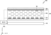
빔 편향기(500)는 소정 파장 대역의 편광을 제1편광으로 변환시키는 제1 파장 선택 편광자(wavelength selective polarizer)(100)와 파장 선택 편광자(100)로부터 입사된 광을 편향시키는 액정 편향부(200) 및 액정 편향부(200)를 제어하는 제어부(400)를 포함한다.The
파장 선택 편광자(100)는 입사광의 위상을 지연시켜 편광을 변환시키는 소자로서, 특정 파장 대역의 광에 대해서 이러한 작용을 하도록 물질이 정해진다. 예를 들어, 파장 선택성을 가지는 광학적 이방성(optically anisotropic) 물질로서 폴리머나 무기 재료등이 사용될 수 있다. 광학적 이방성은 입사광의 편광에 따라 다른 굴절률을 나타내는 성질이며, 파장 선택성을 가지는 광학적 이방성 물질은 특정 파장 대역의 광의 편광을 변환시키도록 적용될 수 있다.The wavelength
파장 선택 편광자(100)는 입사광 중 소정 파장 대역의 광, 예를 들어 적색광의 편광을 제1편광, 예를 들어, 도면에서 x 방향으로 나타나는 P 편광으로 변환시킬 수 있다. 소정 파장 대역의 광은 예를 들어, 적색 파장 대역, 녹색 파장 대역 또는 청색 파장 대역이 될 수 있다. 파장 선택 편광자(100)를 채용하는 것은 액정 편향부(200)의 액정 분자(LC)의 장축(MA) 방향에 해당하는 편광의 광만이 액정 편향부(200)에서 제어되는 성질을 이용하기 위한 것이다. 이러한 성질에 따라, 특정 파장 대역의 광만이 액정 편향부(200)에서 방향 제어될 수 있다. 이에 대해서는 보다 상세히 후술하기로 한다.The wavelength
액정 편향부(200)는 액정 분자(LC)들을 포함하는 액정층(250)과, 액정 분자(LC)들을 제어하기 위한 제1 전극부(230), 제2 전극부(270)를 포함한다. 서로 마주보며 나란하게 배치된 제1 기판(210) 및 제2 기판(290) 상에 각각 제1 전극부(230)와 제2 전극부(270)가 배치될 수 있고, 두 기판(210)(290) 사이에 액정층(250)이 배치된다. 제1기판(210) 및 제2기판(290)은 절연 기판일 수 있고, 유리 또는 투명 플라스틱으로 이루어질 수 있다.The liquid
제1 전극부(230)는 인가 전압이 개별적으로 조절되는 복수의 서브 전극을 포함할 수 있다. 서브 전극들은 일방향, 예를 들어, y방향으로 연장된 스트라이프 형상을 가질 수 있고, x 방향을 따라 나란하게 배치될 수 있다. 제2 전극부(270)는 평판형의 공통 전극일 수 있고, 제1 전극부(230)를 이루는 각각의 서브 전극과의 전압을 형성하기 위한 기준 전압이 인가될 수 있다. 제1 전극부(230), 제2 전극부(270)는 투명 전도성 물질, 예를 들어, ITO(indium-tin-oxide), IZO(indium-zinc-oxide), ITZO(indium-tin-zinc-oxide)로 이루어질 수 있다.The
액정 분자(LC)들은 장축(MA) 방향이 일방향, 예를 들어, x 방향과 나란하도록 초기 배열된다. 이 방향은 파장 선택 편광자(100)가 변환시킨 제1편광 방향이다. 제1기판(210), 제2기판(290)에는 액정 배향을 위한 배향층(alignment layer)(미도시)이 더 마련될 수 있다.The liquid crystal molecules LC are initially arranged so that the major axis MA direction is parallel to one direction, for example, the x direction. This direction is the first polarization direction converted by the wavelength
액정 편향부(200)는 도 2에 도시된 바와 같이, 입사광의 광을 편향시키는 광경로 변환면(220a)을 가질 수 있다. 광경로 변환면(220a)은 제1 전극부(230)와 제2 전극부(270) 사이에 인가되는 전압에 의해 액정 분자(LC)들의 배열이 변함에 따라 형성될 수 있다. 광경로 변환면(220a)의 형태는 인가 전압에 따라 가변될 수 있다. 광경로 변환면(220a)이 형성되는 것은 액정 분자(LC)의 장축(MA) 방향의 굴절률과, 이에 수직인 단축 방향의 굴절률이 서로 다르기 때문이다. 다시 말하면, 액정 분자(LC)에 입사하는 광 중, 장축 방향과 나란한 편광의 광과 이에 수직인 방향에 나란한 편광의 광에 대해 액정 분자(LC)는 서로 다른 굴절률을 나타내기 때문이다. As shown in FIG. 2 , the liquid
도 1과 같이, 제1 전극부(230), 제2 전극부(270) 사이에 전압이 인가되지 않은 초기 배열 상태에서, 액정 분자(LC)들은 모두 나란한 방향으로 정렬되어 있으며, 일정한 편광의 광에 대해 굴절률은 어느 위치에서나 동일하게 나타난다.As shown in FIG. 1 , in an initial arrangement state in which no voltage is applied between the
한편, 도 2와 같이, 제1 전극부(230)와 제2 전극부(270) 사이에 인가된 전압에 따라 액정층(250)에 소정의 전기장 분포가 형성된 경우, 액정 분자(LC)들이 전기장 방향에 의존하여 정렬하게 된다. 예를 들어, 액정 분자(LC)들은 유전율 이방성이 양인 경우 방향자, 즉, 장축 방향이 전기장 방향으로 배열되며, 유전율 이방성이 음인 경우에는 장축 방향이 전기장 방향에 수직하게 배열될 수 있다. 제1 전극부(230)를 구성하는 서브 전극들에 서로 다른 전압이 인가될 수 있고, 이에 따라, 각 위치에서 액정 분자(LC)들이 정렬된 형태는 서로 다르게 된다. 액정 분자(LC)들은 장축과 단축 방향의 굴절률이 서로 다르기 때문에, 액정 분자(LC)들의 방향자 분포에 따라 굴절률 구배(index gradient)를 가질 수 있다. 광경로 변환면(220a)은 액정층(250) 내에서 굴절률 구배를 굴절률 변화가 일어나는 경계면으로 나타낸 것이며, 이러한 경계면에서 입사광의 굴절이 일어나 소정 방향으로 편향된 광이 액정 편향부(200)로부터 출사된다. 광경로 변환면(220a)의 기울기는 액정층(250)내의 전기장 분포에 따라 액정 분자(LC)들의 방향자 분포를 조절하여 조절할 수 있다. 다시 말해, 입사광의 편향 방향이 제1 전극부(230), 제2 전극부(270) 간에 인가되는 전압에 따라 조절될 수 있다.Meanwhile, as shown in FIG. 2 , when a predetermined electric field distribution is formed in the
한편, 이러한 광경로 변환면(220a)은 액정 분자(LC)의 방향자 배열에 의해 형성되는 것으로, 액정 분자(LC)의 장축 방향이 액정층(250)의 각 위치에서 다르기 때문에 나타난다. 따라서, 광경로 변환면(220a)은 액정 분자(LC)의 초기 배열 상태의 장축 방향과 나란한 방향의 편광, 예를 들어, x 방향과 나란한 편광의 광에 대해서만 작용한다. 이하, x 방향과 나란한 편광은 제1편광이라 하며, ↔으로 표시하기로 한다.Meanwhile, the light
도 2와 같이 액정 분자(LC)들이 배열될 때, 각 위치에서 액정 분자(LC)의 장축 방향은 다르지만, 단축 방향은 y방향으로 동일하다. 따라서, 액정층(250)에 입사하는 광의 편광이 y 방향으로 편광된 광인 경우, 편향은 일어나지 않는다. 이하, y 방향과 나란한 편광은 제2편광이라 하며, ⊙으로 표시하기로 한다.When the liquid crystal molecules LC are arranged as shown in FIG. 2 , the long axis direction of the liquid crystal molecules LC is different at each position, but the short axis direction is the same as the y direction. Accordingly, when the polarization of the light incident on the
다시 말하면, 액정층(250)에 입사하는 광이 x 방향과 나란하게 편광된 제1편광(↔)인 경우, 광경로 변환면(220a)에 의해 그 기울어진 각도에 따라 소정 방향으로 편향되고, y 방향과 나란한 방향으로 편광된 제2편광(⊙)의 광이 입사하는 경우, 편향되지 않고 액정층(250)을 그대로 통과한다.In other words, when the light incident on the
도 3은 도 1의 빔 편향기에 구비되는 파장 선택 편광자를 통과하는 광의 컬러별 편광 변환을 예시적으로 보인다.FIG. 3 illustratively shows polarization conversion for each color of light passing through a wavelength selective polarizer provided in the beam deflector of FIG. 1 .
파장 선택 편광자(100)는 예를 들어, 적색 파장 대역의 광의 편광을 제1편광(↔)으로 변화시킬 수 있다. 파장 선택 편광자(100)에 제2편광(⊙)의 백색광(LW)이 입사하는 경우, 백색광(LW)에 포함되는 적색광(LR), 녹색광(LG), 청색광(LB)은 파장 선택 편광자(100)에 의해 서로 다른 편광으로 출사된다. 파장 선택 편광자(100)가 편광 변환 시키는 파장 대역이 적색광(LR)의 경우, 제1편광(↔)의 광으로 출사되고, 녹색광(LG)과 청색광(LB)은 입사할 때와 동일한 제2편광(⊙)으로 출사된다.For example, the wavelength
파장 선택 편광자(100)의 이러한 성질을 이용하여, 액정 편향부(200)에 입사되는 광의 편광을 컬러별로 다르게 조절하는 경우, 특정 파장 대역의 광만을 편향시키는 것이 가능하다.When the polarization of light incident on the liquid
파장 대역을 선택하여 광을 편향시키는 것은 빔 편향기가 디스플레이 장치에 채용될 때 일어나는 산란 현상을 줄이는데 기여할 수 있다.Deflecting light by selecting a wavelength band can contribute to reducing a scattering phenomenon that occurs when a beam deflector is employed in a display device.
도 4a 및 도 4b는 일반적인 빔 편향기에 의해 일어날 수 있는 빛의 산란 현상 및 이를 줄이는 방안을 설명하는 개념도이다.4A and 4B are conceptual views illustrating a light scattering phenomenon that may occur by a general beam deflector and a method of reducing it.
도 4a를 참조하면, 빔 편향기에 입사된 백색광(LW)은 광경로 변환면(20a)에 의해 굴절되며 진행방향이 편향된다. 편향 방향은 광경로 변환면(20a)을 경계면으로 하는 두 매질의 굴절률 차이와 광경로 변환면(20a)이 기울어진 각도에 의해 정해지는데, 매질의 굴절률은 입사광의 파장 대역에 따라 실질적으로 조금씩 차이가 있다. 따라서, 백색광(LW)이 광경로 변환면(20a)에서 편향될 때, 적색광(LR), 녹색광(LG), 청색광(LB)은 미세한 경로차를 나타내게 된다. 이는 산란 현상으로 나타나며 화질 저하의 원인이 될 수 있다.Referring to FIG. 4A , white light (LW ) incident to the beam deflector is refracted by the optical
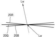
도 4b를 참조하면, 이러한 산란 현상을 없애기 위해, 백색광(LW)이 각 컬러 별로 다른 광경로 변환면(20R)(20G)(20B)에서 편향되어 동일한 방향으로 편향되는 것을 보인다. 이러한 구동을 위해, 시분할 방식의 경우, 첫번째 시간 프레임에서 적색광을 소정 방향으로 편향시키는 광경로 변환면(20R)을 형성하고, 두번째 시간 프레임에서 녹색광을 같은 방향으로 편향시키도록 다른 각도로 기울어진 광경로 변환면(20G)을 형성하고, 세번째 시간 프레임에서 청색광을 같은 방향으로 편향시키도록, 광경로 변환면(20R)(20G)와는 다른 각도로 기울어진 광경로 변환면(20B)을 형성한다. 이러한 시간 프레임의 간격을 충분이 짧게 하여 입사된 백색광(LW)이 동일한 방향으로 동시에 편향되는 것으로 인지될 수 있다.Referring to FIG. 4B , in order to eliminate this scattering phenomenon, it is shown that the white light (LW ) is deflected in the same direction by being deflected on different optical
공간 분할 방식의 경우, 빔 편향기의 영역을 나누어, 일영역에서는 적색광을 소정 방향으로 편향시키는 광경로 변환면(20R)을 형성하고, 다음 영역에서는 녹색광을 같은 방향으로 편향시키도록 다른 각도로 기울어진 광경로 변환면(20G)을 형성하고, 다음 영역에서 청색광(LB)을 같은 방향으로 편향시키도록, 다른 각도로 기울어진 광경로 변환면(20B)을 형성한다. 이러한 영역 간격을 충분히 작게 하여 입사된 백색광(LW)이 동일한 방향으로 편향되는 것으로 인지될 수 있다.In the case of the space division method, the area of the beam deflector is divided to form an optical
실시예에 따른 빔 편향기는 도 4b와 같이, 입사된 백색광(LW)에 포함된 적색광, 녹색광, 청색광을 동일한 방향으로 편광시키도록 광경로 변환면(20R)(20G)(20B)을 따로 구성하되, 광경로 변환면(20R)(20G)(20B)은 해당 컬러만을 편향시키도록 하여, 위의 공간 분할 방식이나 시분할 방식과는 다른 구동 방식을 선택하고 있다.As shown in FIG. 4B, the beam deflector according to the embodiment separately configures optical
이하, 다양한 실시예들에 따른 빔 편향기들을 살펴보기로 한다.Hereinafter, beam deflectors according to various embodiments will be described.
도 5는 다른 실시예에 따른 빔 편향기의 개략적인 구조를 보이는 단면도이다.5 is a cross-sectional view showing a schematic structure of a beam deflector according to another embodiment.
빔 편향기(501)는 적색 파장 대역의 편광을 제1편광(↔)으로 변환시키는 제1 파장 선택 편광자(wavelength selective polarizer)(101)와 제1 파장 선택 편광자(101)로부터 입사된 광을 편향시키는 제1 액정 편향부(201) 및 제1 액정 편향부(201)를 제어하는 제어부(400)를 포함한다.The
제1 액정 편향부(201)는 액정층(250)을 이루는 액정 분자(미도시)들의 거동에 의해 가변되는 제1 광경로 변환면(220R)을 구비한다. 이하의 도면들에서 액정 분자의 도시는 생략하기로 한다. 제1 광경로 변환면(220R)은 적색광(LR)을 소정의 제1방향(A1)으로 편향시키도록 제어부(400)에서 제1 전극부(230)와 제2 전극부(270) 간에 인가하는 전압에 의해 그 기울기가 조절된다.The first liquid
빔 편향기(501)에 백색광(LW)이 입사되면, 제1 파장 선택 편광자(101)는 적색광(LR)은 제1편광(↔)으로 변환시키고 녹색광(LG)과 청색광(LB)은 제2편광(⊙) 상태를 유지한 채 출광시키고, 출광된 광들은 제1 액정 편향부(201)에 입사한다.When white light (LW ) is incident on the
제1 액정 편향부(201)의 제1 광경로 변환면(220R)은 전술한 바와 같이, 제1편광(↔)의 광에 대해서만 굴절 작용을 나타내며, 따라서, 제1편광(↔)의 적색광(LR)은 제1방향(A1)으로 편향되고, 제2편광(⊙)의 녹색광(LG), 청색광(LB)은 편향되지 않고 빔 편향기(501)를 출사한다.As described above, the first light
도 6은 또 다른 실시예에 따른 빔 편향기의 개략적인 구조를 보이는 단면도이다.6 is a cross-sectional view showing a schematic structure of a beam deflector according to another embodiment.
빔 편향기(502)는 제1 파장 선택 편광자(101)의 입사 측에 편광자(300)가 더 구비되는 점에서 도 5의 빔 편향기(501)와 차이가 있다. 편광자(300)는 제1 파장 선택 편광자(101)에 제1편광(↔)과 수직인 제2편광(⊙)의 광이 입사되도록, 제2편광(⊙) 방향의 편광축을 갖는다. 편광자(300)는 제1편광(↔)의 광은 흡수하고, 제2편광(⊙)의 광을 투과시키는 구성을 가질 수 있다.The
도 5에서 설명한 바와 같이, 제1 액정 편향부 (201)에는 적색광(LR)은 제1편광(↔)으로, 녹색광(LG), 청색광(LB)은 제2편광(⊙)으로 입사하여야 적색광(LR)만이 편향되어 출사되게 된다. 이러한 동작을 위하여, 제1 파장 선택 편광자(101)에는 제2편광(⊙)의 백색광(LW)이 입사되는 것으로 설명되었다.As described in FIG. 5, red light (LR ) is incident to the first liquid
본 실시예의 빔 편향기(501')는 제2편광(⊙) 방향의 편광축을 가지는 편광자(300)를 더 구비함으로써, 다양한 편광 방향을 가지는 백색광(LW)에 대해서도, 적색광(LR)만을 편향시키는 역할을 할 수 있다.The beam deflector 501' of this embodiment further includes a
제1편광(↔)과 제2편광(⊙)이 혼합된 백색광(LW)이 빔 편향기(501')에 입사하면, 편광자(300)에 의해 제2편광(⊙)의 백색광으로 제1 파장 선택 편광자(101)에 입사하게 된다. 다음, 제1 파장 선택 편광자(101)에 의해 적색광(LR)은 제1편광(↔)으로, 녹색광(LG), 청색광(LB)은 제2편광(⊙)으로 제1 액정 편향부(201)에 입사하게 된다. 제1 액정 편향부(201)의 제1 광경로 변환면(220R)은 제1편광(↔)의 광에 대해서만 편향 작용을 하며, 따라서, 적색광(LR)은 제1방향(A1)으로 편향되고, 녹색광(LG), 청색광(LB)은 편향되지 않고 빔 편향기(501')를 출사한다.When white light (LW ) in which the first polarized light (↔) and the second polarized light (⊙) are mixed enters the
도 7은 또 다른 실시예에 따른 빔 편향기의 개략적인 구조를 보이는 단면도이다.7 is a cross-sectional view showing a schematic structure of a beam deflector according to another embodiment.
본 실시예의 빔 편향기(502)는 녹색광(LG)만을 소정 방향으로 편향시키도록 구성되는 점에서 도 5의 빔 편향기(501)와 차이가 있다.The
빔 편향기(502)는 녹색 파장 대역의 편광을 제1편광(↔)으로 변환시키는 제2 파장 선택 편광자(wavelength selective polarizer)(110)와 제2 파장 선택 편광자(110)로부터 입사된 광을 편향시키는 제2 액정 편향부(202) 및 제2 액정 편향부(202)를 제어하는 제어부(400)를 포함한다. 제2 액정 편향부(202)는 가변되는 제2 광경로 변환면(220G)을 구비한다. 제2 광경로 변환면(220G)은 녹색광(LG)을 소정의 제1방향(A1)으로 편향시키도록 제어부(400)에서 제1 전극부(230)와 제2 전극부(270) 간에 인가하는 전압에 의해 그 기울기가 조절된다.The
빔 편향기(502)에 제2편광(⊙)의 백색광(LW)이 입사되면, 녹색광(LG)은 제1편광(↔)으로 변환되고, 적색광(LR)과 청색광(LB)은 제2편광(⊙)으로 유지되도록 제2 파장 선택 편광자(110)를 통과하여 제2 액정 편향부(202)에 입사한다. 제2 액정 편향부(202)의 제2 광경로 변환면(220G)은 녹색광(LG)을 제1방향(A1)으로 편향시키는 기울기를 갖는다. 액정 분자들의 굴절률은 광의 파장에 따라 다소 차이가 있으며 따라서, 녹색광(LG)을 제1방향(A1)으로 편향시키는 제2 광경로 변환면(220G)의 기울기는 적색광(LR)을 제1방향(A1)으로 편향시키는, 도 5의 제1 광경로 변환면(220R)의 기울기와는 다를 수 있다. 광경로 변환면(220G)은 제1편광(↔)의 광에 대해서만 굴절 작용을 나타내며, 따라서, 제1편광(↔)의 녹색광(LG)은 제1방향(A1)으로 편향되고, 제2편광의 적색광(LR), 청색광(LB)은 편향되지 않고 빔 편향기(502)를 출사한다.When white light (LW ) of the second polarization (⊙) is incident on the
도 8은 또 다른 실시예에 따른 빔 편향기의 개략적인 구조를 보이는 단면도이다.8 is a cross-sectional view showing a schematic structure of a beam deflector according to another embodiment.
본 실시예의 빔 편향기(503)는 청색광(LB)만을 소정 방향으로 편향시키도록 구성되는 점에서 도 5의 빔 편향기(501), 도 7의 빔 편향기(502)와 차이가 있다.The
빔 편향기(503)는 청색 파장 대역의 편광을 제1편광으로 변환시키는 제3 파장 선택 편광자(wavelength selective polarizer)(120)와 제3 파장 선택 편광자(120)로부터 입사된 광을 편향시키는 제3 액정 편향부(203) 및 제3 액정 편향부(203)를 제어하는 제어부(400)를 포함한다. 제3 액정 편향부(203)는 가변되는 제3 광경로 변환면(220B)을 구비한다. 제3 광경로 변환면(220B)은 청색광(LB)을 소정의 제1방향(A1)으로 편향시키도록 제어부(400)에서 제1 전극부(230)와 제2 전극부(270) 간에 인가하는 전압에 의해 그 기울기가 조절된다.The
빔 편향기(502)에 제2편광(⊙)의 백색광(LW)이 입사되면, 청색광(LB)은 제1편광(↔)으로 변환되고, 적색광(LR)과 녹색광(LG)은 제2편광(⊙)으로 유지되도록 제3 파장 선택 편광자(120)를 통과하여 제3 액정 편향부(203)에 입사한다.When the white light (LW ) of the second polarization (⊙) is incident on the
제3 액정 편향부(203)의 제3 광경로 변환면(220B)은 청색광(LB)을 제1방향(A1)으로 편향시키는 기울기를 갖는다. 액정 분자들의 굴절률은 광의 파장에 따라 다소 차이가 있으며 따라서, 청색광(LB)을 제1방향(A1)으로 편향시키는 제3 광경로 변환면(220B)의 기울기는 적색광(LR)을 제1방향(A1)으로 편향시키는, 도 5의 제1 광경로 변환면(220R)의 기울기, 녹색광(LG)을 제1방향(A1)으로 편향시키는, 도 6의 제2 광경로 변환면(220G)의 기울기와는 다를 수 있다.The third optical
제3 액정 편향부(203)의 제3 광경로 변환면(220B)은 제1편광(↔)의 광에 대해서만 굴절 작용을 나타내며, 따라서, 제1편광(↔)의 청색광(LB)은 제1방향(A1)으로 편향되고, 제2편광의 적색광(LR), 녹색광(LG)은 편향되지 않고 빔 편향기(502)를 출사한다.The third optical
도 7 및 도 8의 빔 편향기(502)(503)도 도 6의 빔 편향기(501')와 마찬가지로, 편광자(300)를 더 구비할 수 있다. 이 경우, 제1편광(↔)과 제2편광(⊙)이 혼합된 백색광(LW)이 빔 편향기(502)(503)에 입사하여도 편광자(300)에 의해 제1편광(↔)과 제2편광(⊙)이 혼합된 백색광(LW) 중, 제2편광(⊙)의 백색광(LW)만이 제2 파장 선택 편광자(110), 제3 파장 선택 편광자(120)에 입사되게 된다.The
도 9는 또 다른 실시예에 따른 빔 편향기의 개략적인 구조를 보이는 단면도이다.9 is a cross-sectional view showing a schematic structure of a beam deflector according to another embodiment.
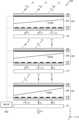
빔 편향기(504)는 서로 다른 파장 대역의 광을 소정 방향으로 편향시키도록 구성된 파장 선택 편광자/액정 편향부의 구성이 광의 진행 방향을 따라 적층된 형태를 갖는다.The
빔 편향기(504)는 제1 파장 대역의 편광을 제1편광(↔)으로 변환시키는 제1 파장 선택 편광자(101)와, 제1 파장 선택 편광자(101)로부터 입사된 광을 편향시키는 제1 광경로 변환면(220R)을 가지는 제1 액정 편향부(201)와, 제1 액정 편향부(201)를 통과한 광의 광경로 상에 배치되어 제2 파장 대역의 광의 편광을 제1편광(↔)으로 변환시키는 제2 파장 선택 편광자 (110)와 제2 파장 선택 편광자(100)로부터 입사된 광을 편향시키는 제2 광경로 변환면(220G)을 가지는 제2 액정 편향부(202)와, 제3 파장 대역의 광의 편광을 제1편광(↔)으로 변환시키는 제3 파장 선택 편광자(120)와 제3 파장 선택 편광자(120)로부터 입사된 광을 편향시키는 제3 광경로 변환면(220B)을 가지는 제3 액정 편향부(203) 및 상기 제1 내지 제3 액정 편향부(201)(202)(203)를 제어하는 제어부(400)를 포함한다.The
제어부(400)는 제1 광경로 변환면(220R), 제2 광경로 변환면(220G), 제3 광경로 변환면(220B)이 각각 제1 파장 대역의 제1편광(↔)의 광, 제2 파장 대역의 제1편광(↔)의 광, 제3 파장 대역의 제1편광(↔)의 광을 서로 같은 제1방향(A1)으로 편향시키도록 서로 다른 각도로 기울어지게 제1 액정 편향부(201), 제2 액정 편향부(202), 제3 액정 편향부(203)를 제어한다.The
빔 편향기(504)가 입사된 백색광(LW)을 제1방향(A1)으로 편향시키는 과정을 살펴보기로 한다.A process in which the
빔 편향기(504)에 입사된 제2편광(⊙)의 백색광(LW)은 제1 파장 선택 편광자(101)에 의해, 제1편광(↔)의 적색광(LR), 제2편광(⊙)의 녹색광(LG), 제2편광(⊙)의 청색광(LB)으로 분리된다.The white light (LW ) of the second polarized light (⊙) incident on the
제1편광(↔)의 적색광(LR), 제2편광(⊙)의 녹색광(LG), 제2편광(⊙)의 청색광(LB)은 제1 액정 편향부(201)에 입사한다. 제1 액정 편항부(201)의 제1 광경로 변환면(220R)은 적색광(LR)을 소정의 제1방향(A1)으로 편향시키는 기울기를 가진다. 또한, 제1 광경로 변환면(220R)은 제1편광(↔)의 광에 대해서만 굴절 작용을 나타내므로, 제1편광(↔)의 적색광(LR)만이 편향되고, 제2편광(⊙)의 녹색광(LG), 제2편광(⊙)의 청색광(LB)은 제1 액정 편향부(201)에서 편향되지 않고 그대로 출사된다.Red light (LR ) of the first polarization (↔), green light (LG ) of the second polarization (⊙), and blue light (LB ) of the second polarization (⊙) are incident on the first liquid
다음, 제1편광(↔)의 적색광(LR)과, 제2편광(⊙)의 녹색광(LG), 제2편광(⊙)의 청색광(LB)이 제2 파장 선택 편광자(112)에 입사한다. 제2 파장 선택 편광자(112)는 녹색광(LG)의 편광을 제1편광(↔)으로 바꾸는 역할을 한다. 또한, 제2 파장 선택 편광자(112)는 제1편광(↔)의 적색광(LR)을 제2편광(⊙)으로 바꾸며, 제2편광(⊙)의 청색광(LB)에는 영향을 주지 않는다. 제2 파장 선택 편광자(112)의 재질로서 녹색에서 적색 파장 대역에 대해 파장 선택성을 가지는 광학적 이방성(optically anisotropic) 물질이 사용될 수 있고, 제2 파장 선택 편광자(112)는 녹색에서 적색 파장 대역의 광의 편광을 90도로 바꿀 수 있다. 제2 파장 선택 편광자(112)에 의해 제2편광(⊙)의 적색광(LR), 제1편광(↔)의 녹색광, 제2편광(⊙)의 청색광(LB)이 제2 액정 편향부(202)에 입사하게 된다.Next, red light (LR ) of the first polarization (↔), green light (LG ) of the second polarization (⊙), and blue light (LB ) of the second polarization (⊙) are transmitted through the second wavelength
제2 액정 편향부(202)의 제2 광경로 변환면(220G)의 기울기는 녹색광(LG)을 제1방향으로 편향시키도록 설정되어 있다. 또한, 이러한 제2 광경로 변환면(220G)은 제1편광(↔)의 광에 대해서만 작용하는 것이므로, 입사된 제2편광(⊙)의 적색광(LR), 제1편광(↔)의 녹색광, 제2편광(⊙)의 청색광(LB) 중, 제1편광(↔)의 녹색광(LG)만이 제2 광경로 변환면(220G)에서 편향되어 제2 액정 편향부(202)를 출사한다. 제2편광(⊙)의 적색광(LR)은 제1 액정 편향부(201)에서 편향된 방향을 유지하고, 제2편광(⊙)의 청색광(LB)은 편향되지 않은 방향을 유지한다.The inclination of the second optical
다음, 제2편광(⊙)의 적색광(LR)과, 제1편광(↔)의 녹색광(LG), 제2편광(⊙)의 청색광(LB)이 제3 파장 선택 편광자(122)에 입사한다. 제3 파장 선택 편광자(120)는 청색광(LB)의 제2편광(⊙)을 제1편광(↔)으로 바꾸는 역할을 한다. 또한, 제3 파장 선택 편광자(122)는 제1편광(↔)의 녹색광(LG)을 제2편광(⊙)으로 바꾸며, 제2편광(⊙)의 적색광(LG)의 편광에는 영향을 주지 않는다. 제3 파장 선택 편광자(122)의 재질로서 청색에서 녹색 파장 대역에 대해 파장 선택성을 가지는 광학적 이방성(optically anisotropic) 물질이 사용될 수 있고, 제3 파장 선택 편광자(122)는 청색에서 녹색 파장 대역의 광의 편광을 90도로 바꿀 수 있다. 제3 파장 선택 편광자(122)에 의해 제2편광(⊙)의 적색광(LR), 제2편광(⊙)의 녹색광, 제1편광(↔)의 청색광(LB)이 제3 액정 편향부(203)에 입사하게 된다.Next, red light (LR ) of the second polarization (⊙), green light (LG ) of the first polarization (↔), and blue light (LB ) of the second polarization (⊙) are transmitted through the third wavelength
제3 액정 편향부(203)의 제3 광경로 변환면(220B)의 기울기는 청색광(LB)을 제1방향으로 편향시키도록 설정되어 있다. 또한, 이러한 제3 광경로 변환면(220B)은 제1편광(↔)의 광에 대해서만 작용하는 것이므로, 입사된 제2편광(⊙)의 적색광(LR), 제2편광(⊙)의 녹색광, 제1편광의 청색광(LB) 중, 제1편광(↔)의 청색광(LB)만이 제3 광경로 변환면(220B)에서 편향되어 제3 액정 편향부(203)를 출사한다. 제2편광(⊙)의 적색광(LR)은 제1 액정 편향부(201)에서 편향된 방향을 계속 유지하고, 제2편광(⊙)의 녹색광(LG)은 제2 액정 편향부(202)에서 편향된 방향을 유지한다.The inclination of the third optical
이와 같이, 빔 편향기(504)에서 출사된 적색광(LR), 녹색광(LG), 청색광(LB)은 같은 제1방향(A1)을 향하게 된다. 제1 내지 제3 광경로 변환면(220R)(220G)(220B)이 겹쳐지게 배치되고 각 광경로 변환면(220R)(220G)(220B)에서 정해진 컬러광만이 편향되는 결과로서, 빔 편향기(504)에 입사된 백색광(LW)은 소정의 원하는 제1방향(A1)으로 편향될 수 있다. 실시예의 빔 편향기(504)는 컬러별로 공간 분할되거나 시간 분할되는 형태로 서로 다른 컬러광을 편향시키는 기존의 빔 편향기 구조에 비해, 간소한 구조를 가지며, 효과적으로 입사광을 원하는 방향으로 편향시킬 수 있다.In this way, the red light (LR ), the green light (LG ), and the blue light (LB ) emitted from the
도 10은 또 다른 실시예에 따른 빔 편향기의 개략적인 구조를 보이는 단면도이다.10 is a cross-sectional view showing a schematic structure of a beam deflector according to another embodiment.
본 실시예의 빔 편향기(505)는 편광자(300)를 더 구비하는 점에서 도 9의 빔 편향기(504)와 차이가 있다.The
도 9의 빔 편향기(504)에는 제2편광(⊙)의 백색광(LW)이 입사되는 것으로 설명하였으나, 본 실시예의 빔 편향기(505)는 제2편광(⊙)의 백색광이 제1 파장 선택 편광자(101)에 입사할 수 있도록, 제2편광(⊙) 방향의 편광축을 갖는 편광자(300)를 더 구비하고 있다. 제1편광(↔)과 제2편광(⊙)이 혼합된 백색광(LW)이 빔 편향기(505)에 입사하는 경우, 제2편광(⊙)의 광만을 투과시키는 편광자(300)에 의해, 제2편광(⊙)의 백색광(LW)이 제1 파장 선택 편광자(101)에 입사하게 된다. 다음, 제1 액정 편향부(201), 제2 파장 선택 편광자(112), 제2 액정 편향부(202), 제3 파장 선택 편광자(122), 제3 액정 편향부(203)를 지나며 소정의 제1방향(A1)으로 편향된 백색광(LW)이 출사된다.It has been described that white light (LW ) of the second polarization (⊙) is incident on the
도 11은 또 다른 실시예에 따른 빔 편향기의 개략적인 구조를 보이는 단면도이다.11 is a cross-sectional view showing a schematic structure of a beam deflector according to another embodiment.
빔 편향기(506)는 출사된 백색광(LW)의 경로를 바꾸는 광경로 변환부재(370)를 더 구비하는 점에서, 도 10의 빔 편향기(505)와 차이가 있다. 제1 액정 편향부(201), 제2 액정 편향부(202), 제3 액정 편향부(293)에 의해 제1방향으로 편향된 광의 방향을 광경로 변환 부재(370)를 이용하여 더 변경할 수 있어서, 원하는 방향을 향하도록 미세 조절할 수 있다.The
도 12는 또 다른 실시예에 따른 빔 편향기의 개략적인 구조를 보이는 단면도이다.12 is a cross-sectional view showing a schematic structure of a beam deflector according to another embodiment.
빔 편향기(507)는 제1 액정 편향부(201) 상에 배치된 제1-2 액정 편향부(205)를 더 포함하는 점에서, 도 5의 빔 편향기(501)와 차이가 있다.The
제1-2 액정 편향부(205)는 액정층(250)을 이루는 액정 분자들의 거동에 따라 가변되는 제1-2 광경로 변환면(220R-1)을 구비한다. 제1 액정 편향부(201)의 제1 광경로 변환면(220R_1)과 제1-2 액정 편향부(205)의 제1-2 광경로 변환면(220R_1)은 가변축이 서로 직교하는 방향이다. 예를 들어, 제1 광경로 변환면(220R)의 가변축은 y 방향이며, 제1-2 광경로 변환면(220R_1)이 가변축은 x 방향이다. 제1 액정 편향부(201)의 제1 전극부(230)의 복수의 서브 전극들은 y 방향으로 연장된 스트라이프 형상을 가지며, x 방향을 따라 나란하게 배열되며 제1-2 액정 편향부(205)의 제1 전극부(240)는 복수의 서브 전극들은 x 방향으로 연장된 스트라이프 형상을 가지며, y 방향을 따라 나란하게 배열될 수 있다. 도면에서 제1-2 액정 편향부(205)는 제1 전극부(240)의 하나의 서브 전극만이 도시되고 있다.The 1-2nd liquid
빔 편향기(507)은 입사광을 편향시킴에 있어, 2축 방향을 별도로 제어하여 원하는 편향 방향을 달성할 수 있는 구조를 갖는다. 입사된 제2편광(⊙)의 백색광은 제1 파장 선택 편광자(101)에 의해 제1편광(↔)의 적색광(LR), 제2편광(⊙)의 녹색광(LG), 제2편광(⊙)의 청색광(LB)으로 분리되어 제1 액정 편향부(201)에 입사한다. 제1 액정 편향부(201)의 제1 광경로 변환면(220R)은 제1편광(↔)에 대해서만 작용하므로, 제1편광(↔)의 적색광(LR)만이 편향되고 제2편광(⊙)의 녹색광(LG), 제2편광(⊙)의 청색광(LB)은 편향되지 않는다. 다음, 제1-2 액정 편향부(205)에 의해, 제1편광(↔)의 적색광(LR)은 가변축을 x축으로 하는 제1-2 광경로 변환면(220R_1)에 의해 추가적으로 편향된다. 마찬가지로, 제1 광경로 변환면(220R)은 제1편광(↔)에 대해서만 작용하므로, 제1편광(↔)의 적색광(LR)만이 추가적으로 편향되고 제2편광(⊙)의 녹색광(LG), 제2편광(⊙)의 청색광(LB)은 편향되지 않는다.The
빔 편향기(507)는 적색광(LR)을 2축 방향으로 편향시키는 것을 예시하여 설명하였으나, 녹색광(LG)을 편향시키는 도 7의 빔 편향기(502), 청색광(LB)을 편향시키는 도 8의 빔 편향기(503)에도 이와 같은 이축 구동 방식으로 편향 방향을 조절하는 구성이 추가될 수 있다.The
또한, 마찬가지로, 도 9의 빔 편향기(506)의 제1 액정 편향부(201), 제2 액정 편향부(202), 제3 액정 편향부(203)도 각각 적색광(LR), 녹색광(LG), 청색광(LB)의 편향 방향의 이축 구동을 위한 추가적인 액정 편향부를 더 포함할 수 있다.Similarly, the first liquid
도 13은 또 다른 실시예에 따른 빔 편향기의 개략적인 구조를 보이는 단면도이다.13 is a cross-sectional view showing a schematic structure of a beam deflector according to another embodiment.
본 실시예의 빔 편향기(508)는 제1 광경로 변환면(222R)이 서로 다른 각도로 기울어진 두 면(R1)(R2)을 포함하는 형상인 점에서, 도 5의 빔 편향기(501)와 차이가 있다. 제어부(400)에서 제1 전극부(230)와 제2 전극부(270) 사이에 인가되는 전압 형태를 조절하여, 제1 광경로 변환면(222R)이 서로 다른 각도로 기울어진 두 면(R1)(R2)을 가지는 형상이 될 수 있다.The
빔 편향기(508)에 입사된 제2편광(⊙)의 백색광(LW)은 제1 파장 선택 편광자(101)에 의해 제1편광(↔)의 적색광(LR), 제2편광(⊙)의 녹색광(LG), 제2편광(⊙)의 청색광(LB)으로 분리되어 제1 액정 편향부(207)에 입사한다. 제1 액정 편향부(207)의 제1 광경로 변환면(222R)은 제1편광(↔)에 대해서만 작용하므로, 제1편광(↔)의 적색광(LR)만이 편향되고 제2편광(⊙)의 녹색광(LG), 제2편광(⊙)의 청색광(LB)은 편향되지 않는다. 한편, 제1 광경로 변환면(222R)이 서로 다른 각도로 기울어진 두 면(R1)(R2)을 포함하고 있으므로, 제1편광(↔)의 적색광(LR) 중 면(R1)에서 굴절된 적색광(LR)과 면(R2)에서 굴절되는 적색광(LR)은 서로 다른 방향을 향하게 된다. 따라서, 입사된 적색광(LR)은 제1방향(A1)을 향하는 광(LR_1) 및 제2방향(LR_2)을 향하는 광으로 공간 분리되게 출사된다.White light (LW ) of the second polarization (⊙) incident on the
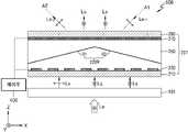
도 14는 또 다른 실시예에 따른 빔 편향기의 개략적인 구조를 보이는 단면도이다.14 is a cross-sectional view showing a schematic structure of a beam deflector according to another embodiment.
빔 편향기(509)는 적색광(LR), 녹색광(LG), 청색광(LB)을 순차적으로 편향시키도록, 제1 파장 선택 편광자(101), 제1 액정 편향부(207), 제2 파장 선택 편광자(112), 제2 액정 편향부(208), 제3 파장 선택 편광자(122), 제3 액정 편향부(209)를 포함한다.The
제1 내지 제3 액정 편향부(207)(208)(209)의 제1 내지 제3 광경로 변환면(222R)(222G)(222B)이 서로 다른 각도로 기울어진 두 면을 포함하는 점에서, 도 9의 빔 편향기(504)와 차이가 있다. 제어부(400)는 제1 광경로 변환면(222R)이 서로 다른 각도로 기울어진 두 면(R1)(R2)을 포함하는 형상이 되도록 제어하여, 제1 액정 편향부(207)에 입사된 적색광(LR)을 두 방향으로 분기하여 편향시키고, 제2 광경로 변환면(222G)이 서로 다른 각도로 기울어진 두 면(G1)(G2)을 포함하는 형상이 되도록 제어하여, 제2 액정 편향부(208)에 입사된 광을 상기 두 방향으로 분기하여 편향시키며, 제3 광경로 변환면(222B)이 서로 다른 각도로 기울어진 두 면(B1)(B2)을 포함하는 형상이 되도록 제어하여, 제3 액정 편향부(209)에 입사된 광을 상기 두 방향으로 분기하여 편향시킨다.The first to third optical
이에 따라, 적색광(LR), 녹색광(LG), 청색광(LB)을 각기 제1방향(A1), 제2방향(A2)으로 나누어 편향되며, 결과적으로 입사된 백색광(LW)은 제1방향(A1)과 제2방향(A2)을 향하는 형태로 분리되어 출사된다. 이러한 두 방향은 빔 편향기(509)가 3차원 디스플레이 장치에 채용될 때, 사용자의 좌안, 우안을 향하는 방향이 될 수 있다.Accordingly, the red light (LR ), the green light (LG ), and the blue light (LB ) are divided into the first direction (A1) and the second direction (A2) and deflected, and as a result, the incident white light (LW ) is The first and second directions A1 and A2 are separated and emitted. When the
본 실시예의 빔 편향기(509)도 제1 파장 선택 편광자(101)에 제2편광(⊙)의 광만을 입사시키도록 제2편광(⊙) 방향의 편광축을 갖는 편광자를 더 구비할 수 있다.The
도 15는 실시예에 따른 3차원 디스플레이 장치의 개략적인 구조를 보이는 단면도이다.15 is a cross-sectional view showing a schematic structure of a 3D display device according to an embodiment.
3차원 디스플레이 장치(1000)는 복수의 파장 대역을 포함하는 가간섭성 광빔을 제공하는 광원(1100), 광원(1100)으로부터의 광을 편향시키는 빔 편향기(1200), 빔 편향기(1200)에서 광을 편향시키는 방향을 제어하는 제어부(1800) 및 입사광을 회절시켜 홀로그램 영상을 형성하는 공간 광변조기(1600)를 포함한다. 또한, 빔 편향부(1200)에 의해 편향된 광을 가이드하여 공간 광변조기(1600)를 향하도록 하는 도광부(1300), 홀로그램 영상을 소정의 공간상에 포커싱 하기 위한 필드렌즈(1500)를 더 구비할 수 있다.The 3D display device 1000 includes a
빔 편향기(1200)는 도 9의 빔 편향기(504), 도 10의 빔 편향기(505), 도 11의 빔 편향기(506), 도 14의 빔 편향기(509)들 중 어느 하나, 이들이 변형된 형태 또는 이들이 조합된 형태가 채용될 수 있다.The
빔 편향기(1200)는 광원(1100)에서의 광을 소정의 두 방향으로 편향시킬 수 있다. L1, L2는 각각 좌안, 우안을 향하는 광이 될 수 있다. 이러한 L1, L2의 형성을 위해 입사광이 제어부(400)의 제어에 의해 각각 두 방향으로 시순차적으로 편향되거나, 또는 도 14의 빔 편향기(509)를 채용하여, 입사광이 두 방향으로 동시에 편향되는 것이 가능하다.The
광원(1100)에서의 광은 빔 편향부(1200)에 의해 편향된 후, 도광부(1300)에 의해 가이드되며 공간 광변조기(1600)에 대응하는 크기로 확대되어 공간 광변조기(1600)를 향하는 방향으로 출사된다. 도광부(1300)에는 빔 편향기(1200)에서 편향된 광이 입사되게 하는 입력 커플러(1310), 도광부(1300)에 의해 가이드되며 진행되는 광의 출사를 위한 출력 커플러(1320)가 더 마련될 수 있다.The light from the
도광부(1300)를 통해 출사되는 두 지향성 빔은 필드 렌즈(1500)를 통해 공간 광변조기(1600)에 입사하게 된다. 공간 광변조기(1600)는 입사광을 변조하기 위한 간섭 무늬를 갖는 홀로그램 패턴을 형성하는 역할을 한다. 공간 광변조기(1600)에서 형성되는 홀로그램 패턴에 의해 입사광이 회절 및 변조됨으로써 소정의 공간 상의 위치에 홀로그램 영상이 재생될 수 있다. 좌안 위치에는 좌안 홀로그램 영상이, 우안 위치에는 우안 홀로그램 영상이 재생될 수 있다.The two directional beams emitted through the
도 16은 다른 실시예에 따른 3차원 디스플레이 장치의 개략적인 구조를 보이는 사시도이다.16 is a perspective view showing a schematic structure of a 3D display device according to another embodiment.
3차원 디스플레이 장치(2000)는 복수의 파장 대역을 포함하는 가간섭성 광빔을 제공하는 광원(2100), 광원(2100)으로부터의 광을 편향시키는 빔 편향기(2300), 빔 편향기(2300)에서 광을 편향시키는 방향을 제어하는 제어부(2800) 및 입사광을 회절시켜 홀로그램 영상을 형성하는 공간 광변조기(2600)를 포함한다. 또한, 광원(2100)에서의 광을 가이드하여 공간 광변조기(2600)를 향하게 하는 도광부(2200), 홀로그램 영상을 소정의 공간상에 포커싱 하기 위한 필드렌즈(2500)를 더 구비할 수 있다.The
빔 편향기(2300)는 도 9의 빔 편향기(504), 도 10의 빔 편향기(505), 도 11의 빔 편향기(506), 도 14의 빔 편향기(509)들 중 어느 하나, 이들이 변형된 형태 또는 이들이 조합된 형태가 채용될 수 있다.The
실시예의 3차원 디스플레이 장치(2000)는 빔 편향기(2300)의 배치 위치에서 도 15의 3차원 디스플레이 장치(1000)와 차이가 있다.The
광원(2100)에서의 광은 도광부(2200)에 의해 가이드되며 공간 광변조기(2600)에 대응하는 크기로 확대된 후, 빔 편향기(2300)에 입사된다. 빔 편향기(2300)는 입사광의 방향을 소정의 원하는 방향으로 편향시키며, 예를 들어, 사용자의 좌안을 향하는 방향 및 우안을 향하는 방향으로 편향시킬 수 있다. 이러한 지향성 광의 형성을 위해 입사광이 제어부(2800)의 제어에 의해 각각 두 방향을 향하도록 시순차적으로 편향되거나, 또는 도 14의 빔 편향기(509)를 채용하여, 입사광이 두 방향으로 동시에 편향되는 것이 가능하다.Light from the
빔 편향기(2300)를 통해 출사되는 두 지향성 빔은 필드 렌즈(2500)를 통해 공간 광변조기(2600)에 입사하게 된다. 공간 광변조기(2600)는 입사광을 변조하기 위한 간섭 무늬를 갖는 홀로그램 패턴을 형성하는 역할을 한다. 공간 광변조기(2600)에서 형성되는 홀로그램 패턴에 의해 입사광이 회절 및 변조됨으로써 소정의 공간 상의 위치에 홀로그램 영상이 재생될 수 있다. 좌안 위치에는 좌안 홀로그램 영상이, 우안 위치에는 우안 홀로그램 영상이 재생될 수 있다.The two directional beams emitted through the
도 15 및 도 16의 3차원 디스플레이 장치(1000)(2000)에는 아이 트래킹 센서가 추가적으로 더 구비될 수 있고, 이를 이용하여 사용자의 좌안 위치, 우안 위치를 추적하여 해당 위치로 편향된 빔이 출사되도록 제어될 수도 있다.An eye tracking sensor may be additionally provided in the
도 15 및 도 16의 3차원 디스플레이 장치(1000)(2000)는 전술한 바와 같은 구성으로 입사광을 산란 현상없이 원하는 방향으로 편향시키는 빔 편향기를 채용하고 있어, 양질의 3차원 영상을 제공할 수 있다.The
100.. 파장 선택 편광자
101.. 제1 파장 선택 편광자
110, 112.. 제2 파장 선택 편광자
120, 122.. 제3 파장 선택 편광자
200.. 액정 편향부
201, 207.. 제1 액정 편향부
202, 208.. 제2 액정 편향부
203, 209.. 제3 액정 편향부
205.. 제1-2 액정 편향부
220a.. 광경로변환면
220R, 222R.. 제1 광경로 변환면
220G, 222G.. 제2 광경로 변환면
220B, 222B.. 제3 광경로 변환면
500, 501, 502, 503, 504, 505, 506, 507, 508, 509, 1200, 2300.. 빔 편향기
1000, 2000.. 3차원 디스플레이 장치100.. Wavelength selective polarizer
101.. First wavelength selective polarizer
110, 112.. second wavelength selective polarizer
120, 122.. third wavelength selective polarizer
200.. liquid crystal deflector
201, 207.. First liquid crystal deflection unit
202, 208.. Second liquid crystal deflection unit
203, 209.. Third liquid crystal deflection unit
205.. 1-2 liquid crystal deflecting unit
220a.. Light path changing surface
220R, 222R.. First optical path changing surface
220G, 222G.. 2nd optical path changing surface
220B, 222B.. Third light path changing surface
500, 501, 502, 503, 504, 505, 506, 507, 508, 509, 1200, 2300.. Beam deflector
1000, 2000.. 3D display device
Claims (20)
Translated fromKorean상기 편광자를 투과한 제2편광의 광 중, 제1 파장 대역의 광의 편광을 제1편광으로 변환시키고, 나머지 파장 대역의 광의 편광은 제2편광으로 유지시키는 제1 파장 선택 편광자(wavelength selective polarizer);
상기 제1 파장 선택 편광자로부터 입사된 광 중, 중, 제1편광 상태로 변환된 제1 파장 대역의 광을 편향시키는 것으로, 액정 분자들을 구비하며, 가변되는 제1 광경로 변환면을 가지는 제1 액정 편향부; 및
상기 제1 광경로 변환면이 조절되도록 상기 제1 액정 편향부를 제어하는 제어부;를 포함하는, 빔 편향기.a polarizer for absorbing incident light of a first polarization and transmitting light of a second polarization perpendicular to the first polarization;
A first wavelength selective polarizer for converting the polarization of light in a first wavelength band among the second polarized lights passing through the polarizer into the first polarization, and maintaining the polarization of the light in the remaining wavelength bands as the second polarization. ;
Among the light incident from the first wavelength-selective polarizer, a first light in a first wavelength band converted to a first polarization state is deflected, and includes liquid crystal molecules and has a variable first optical path conversion surface. a liquid crystal deflection unit; and
A beam deflector including a; control unit for controlling the first liquid crystal deflecting unit so that the first optical path changing surface is adjusted.
상기 액정 분자들은 장축 방향이 상기 제1편광 방향과 나란한 모드로 초기 배열되는, 빔 편향기.According to claim 1,
The liquid crystal molecules are initially arranged in a mode in which a long axis direction is parallel to the first polarization direction, the beam deflector.
제1 액정 편향부는
상기 액정 분자들을 사이에 두고 이격 배치된 제1전극부와 제2전극부를 더 포함하며,
상기 제1전극부와 상기 제2전극부 사이에 인가되는 전압에 따라 상기 제1 광경로 변환면이 가변되는, 빔 편향기.According to claim 1,
The first liquid crystal deflecting unit
Further comprising a first electrode part and a second electrode part spaced apart from each other with the liquid crystal molecules interposed therebetween,
The beam deflector wherein the first optical path changing surface is variable according to a voltage applied between the first electrode unit and the second electrode unit.
상기 제1전극부는 인가 전압이 개별적으로 조절되는 복수의 서브 전극을 포함하는, 빔 편향기.According to claim 4,
The first electrode unit includes a plurality of sub-electrodes to which the applied voltage is individually adjusted, the beam deflector.
상기 제1 액정 편향부 상에 배치되고, 액정 분자들을 구비하며, 상기 제1 광경로 변환면과 가변축이 서로 다르게 가변되는 제1-2 광경로 변환면을 가지는 제1-2 액정 편향부;를 더 포함하는, 빔 편향기.According to claim 1,
a 1-2 liquid crystal deflecting unit disposed on the first liquid crystal deflecting unit, including liquid crystal molecules, and having a 1-2 optical path changing surface having a variable axis different from that of the first optical path changing surface; Further comprising a beam deflector.
상기 제어부는 상기 제1 광경로 변환면이 서로 다른 각도로 기울어진 두 면을 포함하는 형상이 되도록 제어하여, 상기 제1 액정 편향부에 입사된 광을 두 방향으로 분기하여 편향시키는, 빔 편향기.According to claim 1,
The control unit controls the first optical path changing surface to have a shape including two surfaces inclined at different angles to divert and deflect the light incident to the first liquid crystal deflector in two directions. .
상기 제1 액정 편향부를 통과한 광의 광경로 상에 배치된 것으로, 제2 파장 대역의 광의 편광을 제1편광으로 변환시키는 제2 파장 선택 편광자(wavelength selective polarizer);와
상기 제2 파장 선택 편광자로부터 입사된 광을 편향시키는 것으로, 액정 분자들을 구비하며, 가변되는 제2 광경로 변환면을 가지는 제2 액정 편향부;를 더 포함하는, 빔 편향기.According to claim 1,
a second wavelength selective polarizer disposed on an optical path of light passing through the first liquid crystal deflector and converting polarization of light in a second wavelength band into first polarization; and
A second liquid crystal deflector for deflecting light incident from the second wavelength selective polarizer, including liquid crystal molecules, and having a variable second light path changing surface; further comprising a beam deflector.
상기 제2 액정 편향부를 통과한 광의 광경로 상에 배치된 것으로, 제3 파장 대역의 광의 편광을 제1편광으로 변환시키는 제3 파장 선택 편광자(wavelength selective polarizer);와
상기 제3 파장 선택 편광자로부터 입사된 광을 편향시키는 것으로, 액정 분자들을 구비하며, 가변되는 제3 광경로 변환면을 가지는 제3 액정 편향부;를 더 포함하는, 빔 편향기.According to claim 8,
a third wavelength selective polarizer disposed on an optical path of light passing through the second liquid crystal deflector and converting polarization of light in a third wavelength band into first polarization; and
A third liquid crystal deflector for deflecting light incident from the third wavelength selective polarizer, including liquid crystal molecules, and having a variable third optical path changing surface; further comprising a beam deflector.
상기 제1 파장 선택 편광자에 상기 제1편광과 수직인 제2편광의 광이 입사되도록, 상기 제2편광 방향의 편광축을 가지는 편광자를 더 포함하는, 빔 편향기.According to claim 9,
The beam deflector further comprises a polarizer having a polarization axis in the second polarization direction so that light of second polarization perpendicular to the first polarization is incident on the first wavelength selection polarizer.
상기 제어부는
상기 제1 광경로 변환면, 상기 제2 광경로 변환면, 상기 제3 광경로 변환면이 각각 제1 파장 대역의 제1편광의 광, 제2 파장 대역의 제1편광의 광, 제3 파장 대역의 제1 편광의 광을 서로 같은 제1방향으로 편향시키도록 서로 다른 각도로 기울어지게 상기 제1 액정 편향부, 제2 액정 편향부, 제3 액정 편향부를 제어하는, 빔 편향기.According to claim 9,
The control unit
The first optical path changing surface, the second optical path changing surface, and the third optical path changing surface may each have a first polarized light in a first wavelength band, a first polarized light in a second wavelength band, and a third wavelength. A beam deflector that controls the first liquid crystal deflecting unit, the second liquid crystal deflecting unit, and the third liquid crystal deflecting unit to tilt at different angles so as to deflect light of a first polarization of a band in the same first direction.
상기 제1 액정 편향부, 제2 액정 편향부, 제3 액정 편향부에 의해 상기 제1방향으로 편향된 광을 다른 방향으로 변환하는 광경로 변환 부재;를 더 포함하는, 빔 편향기.According to claim 11,
The beam deflector further includes a light path changing member for converting the light deflected in the first direction by the first liquid crystal deflecting unit, the second liquid crystal deflecting unit, and the third liquid crystal deflecting unit into another direction.
상기 제어부는
상기 제1 광경로 변환면이 서로 다른 각도로 기울어진 두 면을 포함하는 형상이 되도록 제어하여, 상기 제1 액정 편향부에 입사된 광을 두 방향으로 분기하여 편향시키고,
상기 제2 광경로 변환면이 서로 다른 각도로 기울어진 두 면을 포함하는 형상이 되도록 제어하여, 상기 제2 액정 편향부에 입사된 광을 상기 두 방향으로 분기하여 편향시키며,
상기 제3 광경로 변환면이 서로 다른 각도로 기울어진 두 면을 포함하는 형상이 되도록 제어하여, 상기 제3 액정 편향부에 입사된 광을 상기 두 방향으로 분기하여 편향시키는, 빔 편향기.According to claim 9,
The control unit
The first optical path changing surface is controlled to have a shape including two surfaces inclined at different angles to divert and deflect the light incident to the first liquid crystal deflecting unit in two directions;
Controlling the second optical path changing surface to have a shape including two surfaces inclined at different angles to divert and deflect light incident to the second liquid crystal deflection unit in the two directions;
A beam deflector that controls the third optical path changing surface to have a shape including two surfaces inclined at different angles to divert and deflect light incident to the third liquid crystal deflecting unit in the two directions.
상기 제1 액정 편향부, 제2 액정 편향부, 제3 액정 편향부에 의해 상기 두 방향으로 편향된 광을 다른 방향으로 변환하는 광경로 변환 부재;를 더 포함하는, 빔 편향기.According to claim 13,
A beam deflector further comprising: an optical path changing member for converting the light deflected in the two directions by the first liquid crystal deflecting unit, the second liquid crystal deflecting unit, and the third liquid crystal deflecting unit into other directions.
상기 광원에서 제공된 광 중 제1편광의 광은 흡수하고 상기 제1편광과 수직인 제2편광의 광을 투과시키는 편광자;
상기 광원으로부터의 광을 편향시키는 것으로,
상기 편광자를 투과한 제2편광의 광 중, 제1 파장 대역의 광의 편광을 제1편광으로 변환시키고, 나머지 파장 대역의 광의 편광은 제2편광으로 유지시키는 제1 파장 선택 편광자와,
상기 제1 파장 선택 편광자로부터 입사된 광 중, 제1편광 상태에 있는 제1파장 대역의 광을 편향시키는 것으로, 액정 분자들을 구비하며, 가변되는 제1 광경로 변환면을 가지는 제1 액정 편향부와,
상기 제1 액정 편향부를 통과한 광의 광경로 상에 배치되어, 제2 파장 대역의 광의 편광을 제1편광으로 변환시키는 제2 파장 선택 편광자와,
상기 제2 파장 선택 편광자로부터 입사된 광 중, 제1편광 상태에 있는 제2 파장 대역의 광을 편향시키는 것으로, 액정 분자들을 구비하며, 가변되는 제2 광경로 변환면을 가지는 제2 액정 편향부와,
상기 제2 액정 편향부를 통과한 광의 광경로 상에 배치되어, 제3 파장 대역의 광의 편광을 제1편광으로 변환시키는 제3 파장 선택 편광자와,
상기 제3 파장 선택 편광자로부터 입사된 광 중, 제1편광 상태에 있는 제3 파장 대역의 광을 편향시키는 것으로, 액정 분자들을 구비하며, 가변되는 제3 광경로 변환면을 가지는 제3 액정 편향부를 포함하는 빔 편향기;
상기 빔 편향기에서 광을 편향시키는 방향을 제어하는 제어부; 및
입사광을 회절시켜 홀로그램 영상을 형성하는 공간 광변조기;를 포함하는, 3차원 디스플레이 장치.a light source providing coherent light beams including a plurality of wavelength bands;
a polarizer for absorbing light of a first polarization among light provided from the light source and transmitting light of a second polarization perpendicular to the first polarization;
By deflecting the light from the light source,
A first wavelength selective polarizer for converting the polarization of light in a first wavelength band among the second polarized lights transmitted through the polarizer into the first polarized light and maintaining the polarization of light in the remaining wavelength bands as the second polarized light;
A first liquid crystal deflector that deflects light of a first wavelength band in a first polarization state among light incident from the first wavelength selective polarizer, includes liquid crystal molecules, and has a variable first optical path changing surface. and,
a second wavelength selection polarizer disposed on an optical path of light passing through the first liquid crystal deflecting unit and converting polarization of light in a second wavelength band into first polarization;
A second liquid crystal deflection unit that deflects light of a second wavelength band in a first polarization state among light incident from the second wavelength selection polarizer, includes liquid crystal molecules, and has a variable second optical path changing surface. and,
a third wavelength selection polarizer disposed on an optical path of light passing through the second liquid crystal deflecting unit and converting polarization of light in a third wavelength band into first polarization;
A third liquid crystal deflecting unit that deflects light of a third wavelength band in a first polarization state among light incident from the third wavelength selective polarizer, includes liquid crystal molecules, and has a variable third optical path changing surface. A beam deflector comprising;
a controller for controlling a direction in which light is deflected by the beam deflector; and
A three-dimensional display device comprising a spatial light modulator that diffracts incident light to form a holographic image.
상기 제1 내지 제3 액정 편향부의 액정 분자들은 장축 방향이 상기 제1편광 방향과 나란한 모드로 초기 배열되는, 3차원 디스플레이 장치.According to claim 15,
The liquid crystal molecules of the first to third liquid crystal deflecting units are initially arranged in a mode in which a major axis direction is parallel to the first polarization direction.
상기 빔 편향기는
상기 제1 액정 편향부 상에 배치되고, 액정 분자들을 구비하며, 상기 제1 광경로 변환면과 가변축이 서로 다르게 가변되는 제1-2 광경로 변환면을 가지는 제1-2 액정 편향부와,
상기 제2 액정 편향부 상에 배치되고, 액정 분자들을 구비하며, 상기 제2 광경로 변환면과 가변축이 서로 다르게 가변되는 제2-2 광경로 변환면을 가지는 제2-2 액정 편향부와,
상기 제3 액정 편향부 상에 배치되고, 액정 분자들을 구비하며, 상기 제3 광경로 변환면과 가변축이 서로 다르게 가변되는 제3-2 광경로 변환면을 가지는 제3-2 액정 편향부를 더 포함하는, 3차원 디스플레이 장치.According to claim 15,
The beam deflector
a 1-2 liquid crystal deflecting unit disposed on the first liquid crystal deflecting unit, including liquid crystal molecules, and having a 1-2 optical path changing surface having a variable axis different from that of the first optical path changing surface; ,
a 2-2 liquid crystal deflecting unit disposed on the second liquid crystal deflecting unit, including liquid crystal molecules, and having a 2-2 optical path changing surface having a variable axis different from that of the second optical path changing surface; ,
A 3-2 liquid crystal deflecting unit disposed on the third liquid crystal deflecting unit, including liquid crystal molecules, and having a 3-2 optical path changing surface having a variable axis different from that of the third optical path changing unit. Including, a three-dimensional display device.
상기 제어부는
상기 제1 광경로 변환면이 서로 다른 각도로 기울어진 두 면을 포함하는 형상이 되도록 제어하여, 상기 제1 액정 편향부에 입사된 광을 두 방향으로 분기하여 편향시키고,
상기 제2 광경로 변환면이 서로 다른 각도로 기울어진 두 면을 포함하는 형상이 되도록 제어하여, 상기 제2 액정 편향부에 입사된 광을 상기 두 방향으로 분기하여 편향시키며,
상기 제3 광경로 변환면이 서로 다른 각도로 기울어진 두 면을 포함하는 형상이 되도록 제어하여, 상기 제3 액정 편향부에 입사된 광을 상기 두 방향으로 분기하여 편향시키는, 3차원 디스플레이 장치.According to claim 15,
The control unit
The first optical path changing surface is controlled to have a shape including two surfaces inclined at different angles to divert and deflect the light incident to the first liquid crystal deflecting unit in two directions;
Controlling the second optical path changing surface to have a shape including two surfaces inclined at different angles to divert and deflect light incident to the second liquid crystal deflection unit in the two directions;
The third optical path changing surface is controlled to have a shape including two surfaces inclined at different angles to divert and deflect the light incident to the third liquid crystal deflecting unit in the two directions.
상기 제어부는
상기 빔 편향기가 광을 편향시키는 방향이 시순차적으로 시청자의 좌안을 향하는 방향 및 우안을 향하는 방향이 되도록 상기 빔 편향기를 제어하는, 3차원 디스플레이 장치.According to claim 15,
The control unit
Controlling the beam deflector so that the direction in which the beam deflector deflects light is a direction toward the left eye and a direction toward the right eye of the viewer sequentially, the three-dimensional display device.
Priority Applications (5)
| Application Number | Priority Date | Filing Date | Title |
|---|---|---|---|
| US16/103,406US10690958B2 (en) | 2017-10-18 | 2018-08-14 | Beam deflector and three-dimensional display device including the same |
| JP2018190865AJP7193295B2 (en) | 2017-10-18 | 2018-10-09 | BEAM DEFLECTOR AND THREE-DIMENSIONAL DISPLAY DEVICE INCLUDING THE SAME |
| CN201811195938.8ACN109683351B (en) | 2017-10-18 | 2018-10-15 | Beam deflector and three-dimensional display device including the beam deflector |
| EP18200770.8AEP3474069B1 (en) | 2017-10-18 | 2018-10-16 | Beam deflector and three-dimensional display device including the same |
| US16/883,596US11262614B2 (en) | 2017-10-18 | 2020-05-26 | Beam deflector and three-dimensional display device including the same |
Applications Claiming Priority (2)
| Application Number | Priority Date | Filing Date | Title |
|---|---|---|---|
| KR1020170135242 | 2017-10-18 | ||
| KR20170135242 | 2017-10-18 |
Publications (2)
| Publication Number | Publication Date |
|---|---|
| KR20190043438A KR20190043438A (en) | 2019-04-26 |
| KR102506445B1true KR102506445B1 (en) | 2023-03-07 |
Family
ID=66281201
Family Applications (1)
| Application Number | Title | Priority Date | Filing Date |
|---|---|---|---|
| KR1020170144220AActiveKR102506445B1 (en) | 2017-10-18 | 2017-10-31 | Beam deflector and 3-dimensional display device including the same |
Country Status (3)
| Country | Link |
|---|---|
| US (1) | US11262614B2 (en) |
| JP (1) | JP7193295B2 (en) |
| KR (1) | KR102506445B1 (en) |
Families Citing this family (4)
| Publication number | Priority date | Publication date | Assignee | Title |
|---|---|---|---|---|
| KR102761434B1 (en) | 2019-05-17 | 2025-02-03 | 삼성전자주식회사 | Backlight unit and holographic display apparatus including the same |
| KR20210117069A (en) | 2020-03-18 | 2021-09-28 | 삼성전자주식회사 | Beam deflector, 3-dimensional display device including the same, and method of deflecting beam |
| KR20210137829A (en)* | 2020-05-11 | 2021-11-18 | 삼성전자주식회사 | Beam deflecting layer and 3 dimensional display device including the same |
| EP4002001A1 (en)* | 2020-11-23 | 2022-05-25 | Samsung Electronics Co., Ltd. | Beam deflection apparatus and holographic display apparatus including the same |
Citations (2)
| Publication number | Priority date | Publication date | Assignee | Title |
|---|---|---|---|---|
| US20130155337A1 (en)* | 2011-07-22 | 2013-06-20 | Keiji Sugiyama | Liquid crystal display device |
| JP2017026874A (en)* | 2015-07-24 | 2017-02-02 | 三菱電機株式会社 | Display device |
Family Cites Families (27)
| Publication number | Priority date | Publication date | Assignee | Title |
|---|---|---|---|---|
| US3836230A (en) | 1973-06-27 | 1974-09-17 | Xerox Corp | Liquid crystal display system |
| JP2579426B2 (en)* | 1993-09-29 | 1997-02-05 | インターナショナル・ビジネス・マシーンズ・コーポレイション | Liquid crystal electro-optical element |
| JPH07134275A (en)* | 1993-11-08 | 1995-05-23 | Mitsubishi Electric Corp | Projection display device |
| US5544268A (en) | 1994-09-09 | 1996-08-06 | Deacon Research | Display panel with electrically-controlled waveguide-routing |
| US6867888B2 (en) | 1996-07-12 | 2005-03-15 | Science Applications International Corporation | Switchable polymer-dispersed liquid crystal optical elements |
| US6169594B1 (en) | 1998-08-24 | 2001-01-02 | Physical Optics Corporation | Beam deflector and scanner |
| US6636276B1 (en) | 1999-09-09 | 2003-10-21 | International Business Machines Corporation | Projection display system with at least two reflective light valves |
| WO2001073504A1 (en) | 2000-03-27 | 2001-10-04 | California Institute Of Technology | Adjustable liquid crystal blazed grating deflector |
| US7057700B2 (en)* | 2001-01-23 | 2006-06-06 | Ricoh Company, Ltd. | Light deflection element, light deflection device and image display device |
| JP2003280041A (en) | 2002-03-20 | 2003-10-02 | Ricoh Co Ltd | Optical deflecting element / optical deflecting device and image display device |
| JP2007065483A (en) | 2005-09-01 | 2007-03-15 | Olympus Corp | Image display device |
| DE102005047261A1 (en)* | 2005-10-01 | 2007-04-05 | Carl Zeiss Jena Gmbh | Display image production method, involves producing display image of display image sequence from subsequence of two recorded exposure images of exposure image sequence, where number of display images is less than number of exposure images |
| JP2008139686A (en) | 2006-12-04 | 2008-06-19 | Ricoh Co Ltd | Image display device and image display method |
| EP2698667B1 (en) | 2011-04-15 | 2018-07-04 | Panasonic Corporation | Light deflecting method using a liquid crystal display device |
| KR101857819B1 (en)* | 2012-03-20 | 2018-05-14 | 엘지디스플레이 주식회사 | Prism using a liquid crystal |
| JP5970994B2 (en) | 2012-07-12 | 2016-08-17 | ソニー株式会社 | Light source device and projector |
| JP2015031790A (en) | 2013-08-01 | 2015-02-16 | 富士フイルム株式会社 | Liquid crystal display |
| TW201531775A (en)* | 2013-12-24 | 2015-08-16 | 富士軟片股份有限公司 | Optical sheet and display device |
| JP2015152835A (en) | 2014-02-17 | 2015-08-24 | キヤノン株式会社 | Wavelength selective polarizing element, optical system, and projection display device |
| KR20160029195A (en) | 2014-09-04 | 2016-03-15 | 삼성디스플레이 주식회사 | Liquid display device |
| JP2016114935A (en) | 2014-12-10 | 2016-06-23 | 三星電子株式会社Samsung Electronics Co.,Ltd. | Light deflection and diffusion sheet, laminated light deflection and diffusion sheet, laminated optical sheet, and liquid crystal display device |
| US9732277B2 (en) | 2015-02-27 | 2017-08-15 | Kent State University | Field induced and controlled heliconical structure of cholesteric liquid crystal |
| KR20170084951A (en)* | 2016-01-13 | 2017-07-21 | 삼성전자주식회사 | Light Deflector and Display Device |
| JP6176371B2 (en) | 2016-07-12 | 2017-08-09 | ソニー株式会社 | projector |
| KR102698292B1 (en) | 2016-11-10 | 2024-08-23 | 삼성전자주식회사 | Liquid crystal light deflector |
| JP6942510B2 (en)* | 2017-04-11 | 2021-09-29 | キヤノン株式会社 | Projection type display device |
| EP3631558A4 (en)* | 2017-05-29 | 2020-12-30 | Eyeway Vision Ltd. | IMAGE PROJECTION SYSTEM |
- 2017
- 2017-10-31KRKR1020170144220Apatent/KR102506445B1/enactiveActive
- 2018
- 2018-10-09JPJP2018190865Apatent/JP7193295B2/enactiveActive
- 2020
- 2020-05-26USUS16/883,596patent/US11262614B2/enactiveActive
Patent Citations (2)
| Publication number | Priority date | Publication date | Assignee | Title |
|---|---|---|---|---|
| US20130155337A1 (en)* | 2011-07-22 | 2013-06-20 | Keiji Sugiyama | Liquid crystal display device |
| JP2017026874A (en)* | 2015-07-24 | 2017-02-02 | 三菱電機株式会社 | Display device |
Also Published As
| Publication number | Publication date |
|---|---|
| KR20190043438A (en) | 2019-04-26 |
| US20200285110A1 (en) | 2020-09-10 |
| JP2019074737A (en) | 2019-05-16 |
| JP7193295B2 (en) | 2022-12-20 |
| US11262614B2 (en) | 2022-03-01 |
Similar Documents
| Publication | Publication Date | Title |
|---|---|---|
| US10690958B2 (en) | Beam deflector and three-dimensional display device including the same | |
| US11262614B2 (en) | Beam deflector and three-dimensional display device including the same | |
| CN104583824B (en) | Polarize different wave length selecting switch | |
| US9632391B2 (en) | Wavelength selective switch employing a LCoS device and having reduced crosstalk | |
| EP1708515B1 (en) | Liquid crystal display device with which a plurality of observers can visually recognize each of two different images displayed on a single LCD panel | |
| KR101695869B1 (en) | Multiview display device | |
| US9696687B2 (en) | Complex spatial light modulator and three-dimensional image display apparatus having the same | |
| WO2015122480A1 (en) | Liquid crystal lenticular lens element, driving method therefor, stereoscopic display device, and terminal device | |
| EP2976671B1 (en) | Wavelength selective switch employing a lcos device and having reduced crosstalk | |
| KR102526760B1 (en) | Beam deflector and 3-dimensional display device including the same | |
| US20130222234A1 (en) | Image display apparatus | |
| US9389430B2 (en) | Light deflection element and image display apparatus using the same | |
| WO2014155984A1 (en) | Image display device | |
| US9488843B2 (en) | Complex spatial light modulator and 3D image display including the same | |
| US11740455B2 (en) | Pupil steered display | |
| US10895798B2 (en) | Beam deflector, holographic display device having the same, and method of driving the beam deflector | |
| US12095974B2 (en) | Beam deflection layer and 3-dimensional display device including the same | |
| US11906757B2 (en) | Beam deflector, 3-dimensional display device including the same, and method of deflecting beam | |
| KR102646791B1 (en) | Focus modulation optical system and holographic display apparatus | |
| CN112198733A (en) | Light beam deflection device and method based on liquid crystal lens and liquid crystal micro-lens array | |
| KR20160087041A (en) | Optical modulatoin device including liquid crystal, and optical display device using the same | |
| KR20220058285A (en) | Beam deflector and 3-dimensional display device including the same | |
| WO2023102985A1 (en) | Display module and display apparatus |
Legal Events
| Date | Code | Title | Description |
|---|---|---|---|
| PA0109 | Patent application | Patent event code:PA01091R01D Comment text:Patent Application Patent event date:20171031 | |
| PG1501 | Laying open of application | ||
| A201 | Request for examination | ||
| PA0201 | Request for examination | Patent event code:PA02012R01D Patent event date:20201019 Comment text:Request for Examination of Application Patent event code:PA02011R01I Patent event date:20171031 Comment text:Patent Application | |
| E902 | Notification of reason for refusal | ||
| PE0902 | Notice of grounds for rejection | Comment text:Notification of reason for refusal Patent event date:20220617 Patent event code:PE09021S01D | |
| E701 | Decision to grant or registration of patent right | ||
| PE0701 | Decision of registration | Patent event code:PE07011S01D Comment text:Decision to Grant Registration Patent event date:20221209 | |
| GRNT | Written decision to grant | ||
| PR0701 | Registration of establishment | Comment text:Registration of Establishment Patent event date:20230228 Patent event code:PR07011E01D | |
| PR1002 | Payment of registration fee | Payment date:20230302 End annual number:3 Start annual number:1 | |
| PG1601 | Publication of registration |