KR102505817B1 - 3d image acquisition device - Google Patents
3d image acquisition deviceDownload PDFInfo
- Publication number
- KR102505817B1 KR102505817B1KR1020200138390AKR20200138390AKR102505817B1KR 102505817 B1KR102505817 B1KR 102505817B1KR 1020200138390 AKR1020200138390 AKR 1020200138390AKR 20200138390 AKR20200138390 AKR 20200138390AKR 102505817 B1KR102505817 B1KR 102505817B1
- Authority
- KR
- South Korea
- Prior art keywords
- light
- image
- lens
- beam splitter
- acquisition device
- Prior art date
- Legal status (The legal status is an assumption and is not a legal conclusion. Google has not performed a legal analysis and makes no representation as to the accuracy of the status listed.)
- Active
Links
- 230000005540biological transmissionEffects0.000claimsdescription38
- 230000003287optical effectEffects0.000claimsdescription33
- 238000000034methodMethods0.000claimsdescription18
- 238000012545processingMethods0.000claimsdescription11
- 238000003491arrayMethods0.000claimsdescription6
- 238000004891communicationMethods0.000claimsdescription6
- 238000010586diagramMethods0.000description10
- 230000000694effectsEffects0.000description2
- 238000005259measurementMethods0.000description2
- 230000001360synchronised effectEffects0.000description2
- 238000002366time-of-flight methodMethods0.000description2
- 230000000295complement effectEffects0.000description1
- 238000007796conventional methodMethods0.000description1
- 238000005516engineering processMethods0.000description1
- 230000001678irradiating effectEffects0.000description1
- 238000004519manufacturing processMethods0.000description1
- 238000007781pre-processingMethods0.000description1
- 230000001681protective effectEffects0.000description1
- 238000002310reflectometryMethods0.000description1
- 239000004065semiconductorSubstances0.000description1
- 230000002123temporal effectEffects0.000description1
- 238000012876topographyMethods0.000description1
- 239000003643water by typeSubstances0.000description1
Images


Classifications
- H—ELECTRICITY
- H04—ELECTRIC COMMUNICATION TECHNIQUE
- H04N—PICTORIAL COMMUNICATION, e.g. TELEVISION
- H04N13/00—Stereoscopic video systems; Multi-view video systems; Details thereof
- H04N13/20—Image signal generators
- H04N13/204—Image signal generators using stereoscopic image cameras
- H04N13/254—Image signal generators using stereoscopic image cameras in combination with electromagnetic radiation sources for illuminating objects
- B—PERFORMING OPERATIONS; TRANSPORTING
- B60—VEHICLES IN GENERAL
- B60R—VEHICLES, VEHICLE FITTINGS, OR VEHICLE PARTS, NOT OTHERWISE PROVIDED FOR
- B60R25/00—Fittings or systems for preventing or indicating unauthorised use or theft of vehicles
- B60R25/30—Detection related to theft or to other events relevant to anti-theft systems
- B60R25/31—Detection related to theft or to other events relevant to anti-theft systems of human presence inside or outside the vehicle
- B—PERFORMING OPERATIONS; TRANSPORTING
- B60—VEHICLES IN GENERAL
- B60R—VEHICLES, VEHICLE FITTINGS, OR VEHICLE PARTS, NOT OTHERWISE PROVIDED FOR
- B60R16/00—Electric or fluid circuits specially adapted for vehicles and not otherwise provided for; Arrangement of elements of electric or fluid circuits specially adapted for vehicles and not otherwise provided for
- B60R16/02—Electric or fluid circuits specially adapted for vehicles and not otherwise provided for; Arrangement of elements of electric or fluid circuits specially adapted for vehicles and not otherwise provided for electric constitutive elements
- B60R16/023—Electric or fluid circuits specially adapted for vehicles and not otherwise provided for; Arrangement of elements of electric or fluid circuits specially adapted for vehicles and not otherwise provided for electric constitutive elements for transmission of signals between vehicle parts or subsystems
- B—PERFORMING OPERATIONS; TRANSPORTING
- B60—VEHICLES IN GENERAL
- B60R—VEHICLES, VEHICLE FITTINGS, OR VEHICLE PARTS, NOT OTHERWISE PROVIDED FOR
- B60R25/00—Fittings or systems for preventing or indicating unauthorised use or theft of vehicles
- B60R25/01—Fittings or systems for preventing or indicating unauthorised use or theft of vehicles operating on vehicle systems or fittings, e.g. on doors, seats or windscreens
- B60R25/04—Fittings or systems for preventing or indicating unauthorised use or theft of vehicles operating on vehicle systems or fittings, e.g. on doors, seats or windscreens operating on the propulsion system, e.g. engine or drive motor
- B—PERFORMING OPERATIONS; TRANSPORTING
- B60—VEHICLES IN GENERAL
- B60R—VEHICLES, VEHICLE FITTINGS, OR VEHICLE PARTS, NOT OTHERWISE PROVIDED FOR
- B60R25/00—Fittings or systems for preventing or indicating unauthorised use or theft of vehicles
- B60R25/10—Fittings or systems for preventing or indicating unauthorised use or theft of vehicles actuating a signalling device
- B60R25/1004—Alarm systems characterised by the type of sensor, e.g. current sensing means
- B—PERFORMING OPERATIONS; TRANSPORTING
- B60—VEHICLES IN GENERAL
- B60R—VEHICLES, VEHICLE FITTINGS, OR VEHICLE PARTS, NOT OTHERWISE PROVIDED FOR
- B60R25/00—Fittings or systems for preventing or indicating unauthorised use or theft of vehicles
- B60R25/10—Fittings or systems for preventing or indicating unauthorised use or theft of vehicles actuating a signalling device
- B60R25/102—Fittings or systems for preventing or indicating unauthorised use or theft of vehicles actuating a signalling device a signal being sent to a remote location, e.g. a radio signal being transmitted to a police station, a security company or the owner
- B—PERFORMING OPERATIONS; TRANSPORTING
- B60—VEHICLES IN GENERAL
- B60R—VEHICLES, VEHICLE FITTINGS, OR VEHICLE PARTS, NOT OTHERWISE PROVIDED FOR
- B60R25/00—Fittings or systems for preventing or indicating unauthorised use or theft of vehicles
- B60R25/30—Detection related to theft or to other events relevant to anti-theft systems
- B60R25/305—Detection related to theft or to other events relevant to anti-theft systems using a camera
- H—ELECTRICITY
- H04—ELECTRIC COMMUNICATION TECHNIQUE
- H04N—PICTORIAL COMMUNICATION, e.g. TELEVISION
- H04N13/00—Stereoscopic video systems; Multi-view video systems; Details thereof
- H04N13/20—Image signal generators
- H04N13/204—Image signal generators using stereoscopic image cameras
- H04N13/207—Image signal generators using stereoscopic image cameras using a single 2D image sensor
- H04N13/236—Image signal generators using stereoscopic image cameras using a single 2D image sensor using varifocal lenses or mirrors
- H—ELECTRICITY
- H04—ELECTRIC COMMUNICATION TECHNIQUE
- H04N—PICTORIAL COMMUNICATION, e.g. TELEVISION
- H04N13/00—Stereoscopic video systems; Multi-view video systems; Details thereof
- H04N13/20—Image signal generators
- H04N13/257—Colour aspects
- B—PERFORMING OPERATIONS; TRANSPORTING
- B60—VEHICLES IN GENERAL
- B60R—VEHICLES, VEHICLE FITTINGS, OR VEHICLE PARTS, NOT OTHERWISE PROVIDED FOR
- B60R25/00—Fittings or systems for preventing or indicating unauthorised use or theft of vehicles
- B60R25/10—Fittings or systems for preventing or indicating unauthorised use or theft of vehicles actuating a signalling device
- B60R2025/1013—Alarm systems characterised by the type of warning signal, e.g. visual, audible
Landscapes
- Engineering & Computer Science (AREA)
- Mechanical Engineering (AREA)
- Multimedia (AREA)
- Signal Processing (AREA)
- Physics & Mathematics (AREA)
- Electromagnetism (AREA)
- Length Measuring Devices By Optical Means (AREA)
- Optical Radar Systems And Details Thereof (AREA)
- Testing, Inspecting, Measuring Of Stereoscopic Televisions And Televisions (AREA)
- Studio Devices (AREA)
- Measurement Of Optical Distance (AREA)
Abstract
Translated fromKoreanDescription
Translated fromKorean본 발명은 3차원 이미지 획득 장치에 관한 것으로서, 더욱 상세하게는 주변 지형 및 피사체 등의 목표물에 대한 이미지를 획득하고 이에 의한 3차원 공간 구조를 측정할 수 있는 3차원 이미지 획득 장치에 관한 것이다.The present invention relates to a 3D image acquisition device, and more particularly, to a 3D image acquisition device capable of acquiring images of surrounding terrain and a target such as a subject and measuring a 3D spatial structure thereby.
종래의 3차원 영상획득 장치로 두 개의 카메라를 사용하여 대상 물체의 대응하는 화소와의 거리 정보를 얻는 수동형 스테레오 비전과 이 스테레오 비전의 카메라 하나를 프로젝터로 대체한 능동형 스테레오 비전과 같은 방식을 적용하고 있다. 그러나 수동형 스테레오 비전은 고속의 장점을 가지고 있으나, 단조로운 환경이나 주위의 조명으로 인해 심각한 영향을 받기 때문에 정확한 3차원 영상을 얻는데 한계가 있으며, 또한, 가시광선 기반의 구조 광(structural)을 사용한 능동형 스테레오 비전은 어느 정도 향상된 3차원 영상을 제공하지만, 가시광선 패턴으로 인해 가정용 로봇 등에 사용할 경우, 사람의 눈에 거슬리게 될 수 있다.As a conventional 3D image acquisition device, the passive stereo vision using two cameras to obtain distance information with the corresponding pixel of the target object and the active stereo vision replacing one camera of the stereo vision with a projector are applied. there is. However, passive stereo vision has the advantage of high speed, but has limitations in obtaining accurate 3D images because it is severely affected by monotonous environments or ambient lighting. In addition, active stereo vision using visible light-based structural light Vision provides a somewhat improved 3D image, but due to the pattern of visible light, when used in a home robot or the like, it may be annoying to the human eye.
이에 최근에는 TOF(Time Of Flight) 방식으로서, 광을 인식 대상체에 조사하여 발광시간과 인식 대상체로부터 반사되는 광의 수광시간 사이의 시간적 차이를 이용함으로써, 카메라와 인식 대상체와의 거리 또는 깊이(depth)를 측정하고 이로부터 3차원 영상을 획득하는 방식이 제공되고 있다.In recent years, as a TOF (Time Of Flight) method, the distance or depth between the camera and the recognition object is determined by using the temporal difference between the light emission time by irradiating light to the recognition object and the light receiving time reflected from the recognition object. A method of measuring and obtaining a 3D image from this is provided.
또한, 3차원 영상획득의 종래의 기술로서 대한민국 공개특허 10-2005-0026949(2005.03.16.)에서는 적외선 플래시 방식의 능동형 3차원 거리 영상 측정 장치가 공지되어 있다. 이에 상기 기술은 플래시 방식의 적외선 광원을 사용하고, 다양한 광 조사 패턴을 이용하여 실시간 거리 측정을 수행하기 위해 DMD(Digital Micromirror Device) 소자를 사용하는 3차원 거리 영상 측정 장치에 관한 것으로서, 본 발명에서와 같이 어레이 형태로 모듈화되어 일정 시간 간격의 펄스 패턴으로 레이저광을 면 발광시키는 빅셀모듈(VCSEL)과 빔스플리터를 사용하여 수신되는 펄스 패턴의 레이저광을 수광하고 시간 타이밍에 따른 위상차를 측정하는 TOF 수신 방식과 컬러 이미지 영상을 결합하여 3차원 공간 구조를 측정할 수 있는 3차원 이미지 획득 장치와는 차이가 있다.In addition, as a conventional technique for 3D image acquisition, an infrared flash type active 3D distance image measuring device is known from Korean Patent Publication No. 10-2005-0026949 (Mar. 16, 2005). Accordingly, the above technology relates to a 3D distance image measurement device using a DMD (Digital Micromirror Device) element to perform real-time distance measurement using a flash-type infrared light source and various light irradiation patterns. TOF, which is modularized in an array form and uses a VCSEL that emits laser light in a pulse pattern at regular time intervals and a beam splitter to receive the received pulse pattern laser light and measure the phase difference according to time timing There is a difference from a 3D image acquisition device that can measure a 3D space structure by combining a reception method and a color image image.
본 발명은 전술한 종래기술의 문제점을 해결하기 위해 도출된 것으로, 그 목적은 본체하우징의 내측에서 펄스 패턴의 레이저를 면 발광으로 발신하는 빅셀(VCSEL)모듈과 적외선과 가시광을 분리 굴절시키는 빔스플리터 및 TOF 수신센서와 영상 이미지센서를 갖는 구조의 장치를 제공하여, TOF 방식의 깊이 정보를 측정하면서도 일반 컬러 영상을 추가로 결합하여 목표물에 대한 3차원 공간 구조를 더욱 정밀하게 측정할 수 있는 3차원 이미지 획득 장치를 제공하고자 하는 것이다.The present invention was derived to solve the above-mentioned problems of the prior art, and its purpose is a VCSEL module that transmits a pulse pattern laser as surface emission from the inside of the main body housing and a beam splitter that separates and refracts infrared and visible light. and a TOF receiving sensor and a video image sensor, which measure the depth information of the TOF method and additionally combine a general color image to measure the 3D spatial structure of the target more precisely. It is intended to provide an image acquisition device.
또한, 본 발명의 다른 목적은 획득되는 3차원 공간 구조의 영상을 네트워크를 통하여 연동되는 스마트폰이나 컴퓨팅 장치에 출력될 수 있도록 하는 3차원 이미지 획득 장치를 제공하고자 하는 것이다.In addition, another object of the present invention is to provide a 3D image acquisition device capable of outputting an acquired image of a 3D spatial structure to a smart phone or a computing device interlocked through a network.
상기 기술적 과제를 해결하기 위한 본 발명의 일 측면에 따른 3차원 이미지 획득 장치는 펄스 레이저광을 외부로 방출하며 외부에서 들어오는 광의 투과를 위한 광투과성 윈도우가 배치되는 본체하우징, 상기 본체하우징 내부의 하단에서 결합되어 장착되어 광의 발신 및 수신 타이밍을 제어하고, 감지된 신호를 외부의 장치에 전달하기 위한 제어부 기판 및 상기 제어부 기판의 상부로 결합되어 적외선 레이저의 발신과 입사되는 외부광의 수신을 위한 광 송수신 유닛이 배치되고, 상기 광 송수신 유닛은 다수의 도트(dot) 어레이 형태로 모듈화되어 펄스 패턴의 적외선 레이저를 면 발광으로 발신하는 빅셀모듈, 목표물에 반사되어 돌아오는 적외선은 수평으로 투과시키고, 입사되는 가시광은 수직으로 굴절시키도록 이루어진 빔스플리터, 상기 빔스플리터로 투과되는 상기 적외선을 수광하여 적외선 영역에서의 구조 영상을 생성하는 TOF 수신센서, 상기 빔스플리터의 하부로 굴절되는 가시광을 수광하여 목표물의 컬러 영상을 생성하는 이미지센서 및 상기 빔스플리터와 TOF 수신센서의 적외선 수신 경로 상에 위치하는 IR 필터렌즈, 상기 빔스플리터와 이미지센서의 가시광 수신 경로 상에 위치하는 가시광 필터렌즈를 포함하여 이루어질 수 있다.A 3D image acquisition device according to an aspect of the present invention for solving the above technical problem is a main body housing in which a light-transmitting window is disposed for emitting pulsed laser light and transmitting light coming from the outside, and a lower part inside the main body housing. A control board for controlling the transmission and reception timing of light and transmitting a detected signal to an external device coupled and mounted thereon and a light transmission and reception for transmitting infrared laser and receiving incident external light coupled to the upper part of the control board unit is arranged, and the optical transmission/reception unit is modularized in the form of a plurality of dot arrays, and the vixel module transmits the infrared laser of the pulse pattern as surface light emission, and the infrared rays reflected from the target are transmitted horizontally and incident A beam splitter configured to refract visible light vertically, a TOF receiving sensor that receives the infrared rays transmitted through the beam splitter to generate a structural image in the infrared region, and a target color sensor that receives the visible light refracted below the beam splitter to generate a structural image in the infrared region. It may include an image sensor generating an image, an IR filter lens positioned on an infrared receiving path of the beam splitter and the TOF receiving sensor, and a visible light filter lens positioned on a visible light receiving path of the beam splitter and the image sensor.
또한, 본 발명의 상기 IR 필터렌즈와 가시광 필터렌즈는 상기 빔스플리터와 일정 간격 이격되어 광 수신 경로 상에 위치할 수 있다.In addition, the IR filter lens and the visible light filter lens of the present invention may be spaced apart from the beam splitter at a predetermined interval and positioned on a light receiving path.
또한, 본 발명의 상기 빔스플리터는 큐브타입(Cube Type)으로 형성되고, 상기 IR 필터렌즈와 가시광 필터렌즈는 상기 빔스플리터의 광 굴절 방향에서 일체형으로 결합되어 이루어질 수 있다.In addition, the beam splitter of the present invention may be formed in a cube type, and the IR filter lens and visible light filter lens may be integrally coupled in a light refraction direction of the beam splitter.
또한, 상기 기술적 과제를 해결하기 위한 본 발명의 다른 측면에 따른 3차원 이미지 획득 장치는 펄스 레이저광을 외부로 방출하며 외부에서 들어오는 광의 투과를 위한 광투과성 윈도우가 배치되는 본체하우징, 상기 본체하우징 내부의 하단에서 결합되어 장착되는 제어부 기판 및 상기 제어부 기판의 상부로 결합되어 적외선 레이저의 발신과 입사되는 외부광의 수신을 위한 광 송수신 유닛이 배치되고, 상기 광 송수신 유닛은 다수의 도트(dot) 어레이 형태로 모듈화되어 펄스 패턴의 적외선 레이저를 면 발광으로 발신하는 빅셀모듈, 목표물에 반사되어 돌아오는 적외선 레이저는 수평으로 투과시키고, 입사되는 가시광은 수직으로 굴절시키도록 이루어진 빔스플리터, 상기 빔스플리터의 뒷단으로 투과되는 상기 적외선 레이저를 수광하여 적외선 영역에서의 구조 영상을 생성하는 TOF 수신센서 및 상기 빔스플리터의 하부로 굴절되는 가시광의 수광을 위하여 다수의 렌즈 요소로 구성되는 카메라렌즈와 상기 카메라렌즈를 광축 방향으로 진퇴 운동시켜 초점조절을 가능하게 하는 렌즈구동부와 목표물의 컬러 영상을 생성하는 이미지센서를 포함하는 카메라 모듈로 이루어지는 것을 특징으로 할 수 있다.In addition, the 3D image acquisition device according to another aspect of the present invention for solving the above technical problem emits pulsed laser light to the outside and has a body housing in which a light-transmitting window for transmitting light coming from the outside is disposed, the inside of the body housing A control board coupled and mounted at the bottom of the control board and an optical transmission/reception unit coupled to the top of the control board for emitting an infrared laser and receiving incident external light are disposed, and the optical transmission/reception unit is in the form of a plurality of dot arrays. A vixel module that is modularized to transmit infrared laser in a pulse pattern by surface emission, a beam splitter configured to horizontally transmit infrared laser reflected from a target and refract incident visible light vertically, to the rear end of the beam splitter A TOF receiving sensor for receiving the transmitted infrared laser to generate a structural image in the infrared region and a camera lens composed of a plurality of lens elements for receiving visible light refracted to the lower part of the beam splitter and the camera lens in the optical axis direction It may be characterized in that it consists of a camera module including a lens driver that enables focus adjustment by moving forward and backward and an image sensor that generates a color image of a target.
또한, 본 발명의 상기 광 송수신 유닛은 상기 윈도우 방향으로 위치되는 전면렌즈가 배치되고, 상기 전면렌즈의 일부분에서 상기 빅셀모듈에서 방출되는 적외선 레이저를 외부로 발산시키기 위한 빅셀렌즈가 상기 전면렌즈의 일정 위치에서 삽입되는 구조 또는 외측에 추가로 장착되어 이루어지는 특징이 있다.In addition, the light transmitting and receiving unit of the present invention has a front lens positioned in the direction of the window, and a big cell lens for radiating infrared laser emitted from the big cell module to the outside from a part of the front lens is a constant of the front lens. It is characterized by being additionally mounted on the outside or the structure inserted at the position.
또한, 본 발명의 상기 빅셀렌즈는 상기 빅셀모듈의 적외선 레이저 광원에 사용된 파장만 통과시키기 위한 대역통과 필터인 특징이 있다.In addition, the vixel lens of the present invention is characterized by being a band pass filter for passing only the wavelength used in the infrared laser light source of the vixel module.
또한, 본 발명의 상기 제어부 기판은 상기 빅셀모듈, TOF 수신센서 및 카메라 모듈과 연동하여 레이저의 발신 및 수신 동작을 제어하는 제어모듈과, 상기 TOF 수신센서에서 수광된 목표물의 구조 영상과 상기 이미지센서에서 수광된 목표물의 컬러 영상 데이터를 결합하여 목표물에 대한 3차원 공간 구조를 측정하는 3D 이미지처리모듈을 포함하는 특징이 있다.In addition, the control board of the present invention includes a control module for controlling transmission and reception operations of a laser in conjunction with the big cell module, the TOF reception sensor, and the camera module, and a structural image of a target received from the TOF reception sensor and the image sensor. It is characterized by including a 3D image processing module for measuring the 3D space structure of the target by combining the color image data of the target received in the light.
또한, 본 발명의 상기 3D 이미지처리모듈은 적외선 구조 영상의 깊이 정보를 계산하고, RGB 컬러 영상과의 텍스쳐 성분의 대비를 비교하여 영상의 선명도가 높은 영상값을 선택하는 알고리즘을 사용하여 3차원 공간 구조를 측정하는 특징이 있다.In addition, the 3D image processing module of the present invention calculates depth information of an infrared structural image, compares the contrast of texture components with an RGB color image, and uses an algorithm to select an image value having high image sharpness. There are features that measure the structure.
또한, 본 발명의 상기 제어부 기판은 상기 제어모듈이 외부 장치와 통신하기 위한 WiFi 또는 LAN 연결 방식을 제공하는 통신모듈을 더 포함하는 특징이 있다.In addition, the control board of the present invention is characterized by further comprising a communication module providing a WiFi or LAN connection method for the control module to communicate with an external device.
또한, 상기 기술적 과제를 해결하기 위한 본 발명의 또 다른 측면에 따른 3차원 이미지 획득 장치는 펄스 레이저광을 외부로 방출하며 외부에서 들어오는 광의 투과를 위한 광투과성 윈도우가 배치되는 본체하우징, 상기 본체하우징 내부의 하단에서 결합되어 장착되어 광의 발신 및 수신 타이밍을 제어하고, 감지된 신호를 외부의 장치에 전달하기 위한 제어부 기판 및 상기 제어부 기판의 상부로 결합되어 적외선 레이저 광의 발신과 입사되는 외부광의 수신을 위한 광 송수신 유닛이 배치되고, 상기 광 송수신 유닛은 다수의 도트(dot) 어레이 형태로 모듈화되어 펄스 패턴의 적외선 레이저를 면 발광으로 발신하는 빅셀모듈, 목표물에 반사되어 돌아오는 적외선 레이저는 수평으로 투과시키고, 입사되는 가시광은 수직으로 굴절시키도록 이루어진 빔스플리터, 상기 빔스플리터로 투과되는 상기 적외선 레이저를 수광하여 적외선 영역에서의 구조 영상을 생성하는 TOF 수신센서 및 상기 빔스플리터의 하부로 굴절되는 가시광을 수광하여 목표물의 컬러 영상을 생성하는 이미지센서를 포함하여 이루어지며, 상기 제어부 기판은 상기 TOF 수신센서에서 수광된 목표물의 구조 영상과 상기 이미지센서에서 수광된 목표물의 컬러 영상 데이터를 결합하여 목표물에 대한 3차원 공간 구조를 측정하는 3D 이미지처리모듈을 포함하는 것을 특징으로 할 수 있다.In addition, the 3D image acquisition device according to another aspect of the present invention for solving the above technical problem is a body housing in which a light-transmitting window for transmitting pulsed laser light is emitted to the outside and light entering from the outside is disposed, the body housing It is coupled and mounted at the bottom of the inside to control the timing of light transmission and reception, and a control board for transmitting a detected signal to an external device and coupled to the top of the control board to transmit infrared laser light and receive incident external light. An optical transmission/reception unit is disposed, and the optical transmission/reception unit is modularized in the form of a plurality of dot arrays, and the vixel module transmits the infrared laser in a pulse pattern as plane emission, and the infrared laser reflected from the target and returned is transmitted horizontally. A beam splitter configured to refract incident visible light vertically, a TOF receiving sensor for receiving the infrared laser transmitted through the beam splitter to generate a structural image in the infrared region, and visible light refracted to the lower portion of the beam splitter It comprises an image sensor that receives light and generates a color image of the target, and the control board combines the structure image of the target received from the TOF receiving sensor and the color image data of the target received from the image sensor to obtain information about the target. It may be characterized by including a 3D image processing module for measuring a 3D spatial structure.
전술한 3차원 이미지 획득 장치의 특징적 구성에 따라, 본 발명은 TOF 방식으로 피사체에 대한 거리 및 깊이 정보를 측정하면서도 컬러영상을 감지할 수 있는 이미지센서를 더 구비하여 정보의 해상도를 높이며, 간단한 동작만으로도 주변 지형 및 피사체 등의 목표물에 대한 정밀한 3차원 공간 구조를 측정할 수 있는 효과가 있다.According to the characteristic configuration of the above-described 3D image acquisition device, the present invention further includes an image sensor capable of detecting a color image while measuring distance and depth information with respect to a subject using a TOF method, thereby increasing the resolution of information and providing simple operation. There is an effect of measuring the precise 3D spatial structure of a target such as a surrounding terrain and a subject with only this.
또한, 본 발명의 3차원 이미지 획득 장치는 구성의 조합을 선택적으로 적용하여 제조 공정을 단순화시킬 수 있으며, 펄스 패턴의 적외선 레이저를 발신하고 적외선과 가시광을 수광하는 광 경로의 정렬(alignment)을 보다 간편하게 할 수 있는 효과가 있다.In addition, the 3D image acquisition device of the present invention can simplify the manufacturing process by selectively applying a combination of configurations, and the alignment of the optical path for transmitting the infrared laser of the pulse pattern and receiving the infrared and visible light is more improved. There is an effect that can be easily done.
또한, 본 발명의 3차원 이미지 획득 장치에서 감지한 목표물의 공간 구조 및 주변 지형 등의 정보 데이터를 외부 장치에 전송할 수 있어 네트워크상에서 데이터를 재가공할 수 있는 장점이 있다.In addition, information data such as the spatial structure of a target and surrounding topography detected by the 3D image acquisition device of the present invention can be transmitted to an external device, so that the data can be reprocessed over a network.
또한, 본 발명의 3차원 이미지 획득 장치는 일반적으로 차량의 라이다 장치의 성능 향상을 위해 적용될 수 있을 뿐만 아니라, 로봇, 선박, 헬기, 드론 등 이동이 가능한 이동 장치에 적용이 가능하고, 아울러 건물, 기둥, 탑 등의 이동이 제한된 고정 장치에도 제한 없이 적용될 수 있는 장점이 있다.In addition, the 3D image acquisition device of the present invention can be applied not only to improve the performance of LIDAR devices of vehicles in general, but also to mobile devices that can move such as robots, ships, helicopters, drones, and buildings. It has the advantage that it can be applied without limitation to fixed devices with limited movement such as columns, towers, etc.
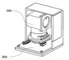
도 1은 본 발명의 일실시예에 따른 3차원 이미지 획득 장치의 본체 하우징을 보여주는 외부 사시도이고,
도 2는 도 1에 따른 3차원 이미지 획득 장치의 내부 구조를 보여주는 예시도이고,
도 3a는 본 발명의 일실시예에 따른 광 송수신 유닛의 구조를 보여주는 예시도이고,
도 3b는 본 발명의 다른 실시예에 따른 도 3a의 광 송수신 유닛의 구조에서 판형 빔스플리터를 보여주는 예시도이다.
도 4는 본 발명의 실시예에 따른 3차원 이미지 획득 장치의 구성을 보여주는 블록도이다.
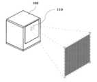
도 5a는 본 발명의 일실시예에 따른 사각 박스 형태의 3차원 이미지 획득 장치의 면 발광을 예시하는 도면이다.
도 5b는 본 발명의 다른 실시예에 따른 원통 형태의 3차원 이미지 획득 장치의 면 발광을 예시하는 도면이다.
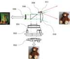
도 6은 본 발명의 일실시예에 따른 카메라 구동부를 구비한 광 송수신 유닛에서의 전체적인 광 송수신 유닛의 구조 및 경로의 설명을 위한 예시도이고,
도 7은 본 발명의 다른 실시예에 따른 카메라 구동부가 없는 광 송수신 유닛의 구조 및 광 송수신 경로의 설명을 위한 예시도이다.
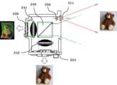
도 8은 본 발명에 따른 IR 필터렌즈와 가시광 필터렌즈가 구비된 광 송수신 유닛의 구조 및 광 경로의 설명을 위한 예시도이고,
도 9는 본 발명의 다른 실시예에 따른 IR 필터렌즈와 가시광 필터렌즈가 빔스플리터와 일체형으로 결합되어 이루어진 광 송수신 유닛의 구조 및 광 경로의 설명을 위한 예시도이다.1 is an external perspective view showing a body housing of a 3D image acquisition device according to an embodiment of the present invention;
2 is an exemplary view showing the internal structure of the 3D image acquisition device according to FIG. 1;
3A is an exemplary view showing the structure of an optical transmission/reception unit according to an embodiment of the present invention;
FIG. 3B is an exemplary view showing a plate-type beam splitter in the structure of the optical transmission/reception unit of FIG. 3A according to another embodiment of the present invention.
4 is a block diagram showing the configuration of a 3D image acquisition device according to an embodiment of the present invention.
5A is a diagram illustrating surface light emission of a 3D image acquisition device having a quadrangular box shape according to an embodiment of the present invention.
5B is a diagram illustrating surface light emission of a cylindrical 3D image acquisition device according to another embodiment of the present invention.
6 is an exemplary view for explaining the overall structure and path of an optical transmission/reception unit in an optical transmission/reception unit having a camera driving unit according to an embodiment of the present invention;
7 is an exemplary view for explaining a structure of an optical transmission/reception unit without a camera driving unit and an optical transmission/reception path according to another embodiment of the present invention.
8 is an exemplary diagram for explaining the structure and light path of a light transmission/reception unit equipped with an IR filter lens and a visible light filter lens according to the present invention;
9 is an exemplary diagram for explaining the structure and light path of a light transmission/reception unit formed by integrally combining an IR filter lens and a visible light filter lens with a beam splitter according to another embodiment of the present invention.
본 명세서 및 청구범위에 사용된 용어나 단어는 통상적이거나 사전적인 의미로 한정해서 해석되어서는 아니 되며, 발명자는 그 자신의 발명을 가장 최선의 방법으로 설명하기 위해 용어의 개념을 적절하게 정의할 수 있다는 원칙에 입각하여 본 발명의 기술적 사상에 부합하는 의미와 개념으로 해석되어야만 한다.The terms or words used in this specification and claims should not be construed as being limited to ordinary or dictionary meanings, and the inventors may appropriately define the concept of terms in order to explain their invention in the best way. It should be interpreted as a meaning and concept consistent with the technical idea of the present invention based on the principle that there is.
따라서 본 명세서에 기재된 실시예와 도면에 도시된 구성은 본 발명의 가장 바람직한 일 실시예에 불과할 뿐이고 본 발명의 기술적 사상을 모두 대변하는 것은 아니므로, 본 출원시점에 있어서 이들을 대체할 수 있는 다양한 균등물과 변형예들이 있을 수 있음을 이해하여야 한다.Therefore, since the embodiments described in this specification and the configurations shown in the drawings are only one of the most preferred embodiments of the present invention and do not represent all of the technical ideas of the present invention, various equivalents that can replace them at the time of the present application It should be understood that there may be waters and variations.
이하 본 발명의 바람직한 실시예를 첨부된 도면을 참조하여 상세히 설명하면 아래와 같다.Hereinafter, a preferred embodiment of the present invention will be described in detail with reference to the accompanying drawings.
도 1은 본 발명의 일실시예에 따른 3차원 이미지 획득 장치의 본체 하우징을 보여주는 외부 사시도이다.1 is an external perspective view showing a body housing of a 3D image acquisition device according to an embodiment of the present invention.
도 1에서와 같이 본 발명의 3차원 이미지 획득 장치는 밀폐된 내부 공간을 가지는 본체하우징(100)과, 본체하우징(100)의 일 측면에서 면 발광의 펄스 레이저광을 외부로 방출하며 외부에서 들어오는 광의 투과를 용이하게 하는 윈도우(110)가 배치된다. 상기 윈도우(110)는 3차원 이미지 획득 장치의 내외부로 광 투과를 용이하게 하고 본체하우징(100)을 보호하기 위한 광투과성 부재로 이루어질 수 있다.As shown in FIG. 1, the 3D image acquisition device of the present invention includes a
이에 본 발명의 본체하우징(100)은 도 1에서와 같이 일정 높이의 사각 박스 형태로 이루어질 수 있으나, 이에 한정하지는 않으며, 도 5b에서와 같이 원통 형상으로 이루어진 하우징에서도 적용될 수 있다.Accordingly, the body housing 100 of the present invention may be formed in the form of a rectangular box of a certain height as shown in FIG. 1, but is not limited thereto, and may also be applied to a housing formed in a cylindrical shape as shown in FIG. 5B.
또한, 도 2는 도 1에 의한 3차원 이미지 획득 장치의 내부 구조를 보여주는 예시도이고, 도 3a는 본 발명의 일실시예에 따른 광 송수신 유닛의 구조를 보여주는 예시도이고, 도 3b는 본 발명의 다른 실시예에 따른 도 3a의 광 송수신 유닛의 구조에서 판형 빔스플리터를 보여주는 예시도이며, 도 4는 본 발명의 일실시예에 따른 3차원 이미지 획득 장치의 구성을 보여주는 블록도이다.In addition, FIG. 2 is an exemplary view showing the internal structure of the 3D image acquisition device of FIG. 1, FIG. 3A is an exemplary view showing the structure of an optical transmission and reception unit according to an embodiment of the present invention, and FIG. 3B is an exemplary view of the present invention. It is an exemplary view showing a plate-type beam splitter in the structure of the optical transmission and reception unit of FIG. 3A according to another embodiment, and FIG. 4 is a block diagram showing the configuration of a 3D image acquisition device according to an embodiment of the present invention.
도시에서와 같이 본 발명의 3차원 이미지 획득 장치는 본체하우징(100)의 내부의 하단에서 결합되어 장착되는 제어부 기판(300), 상기 제어부 기판(300)의 상부에서 광의 송신과 수신을 위한 광 송수신 유닛(200)이 배치되어 이루어지고, 상기 광 송수신 유닛(200)은 전면렌즈(210), 빅셀모듈(220), 빔스플리터(240), TOF 수신센서(230), 카메라 모듈(250)을 포함하여 이루어진다.As shown in the figure, the 3D image acquisition device of the present invention includes a
또한, 광 송수신 유닛(200)은 유닛케이스(201)에 의하여 감싸지는 형태로 보호되도록 이루어지는데, 이에 유닛케이스(201)의 전단에는 본체하우징(100)의 윈도우(110)의 방향으로 위치되는 전면렌즈(210)이 위치되고, 전면렌즈(210)의 뒷단에서는 외부로부터 입사되는 광을 적외선과 가시광의 파장대로 분리하여 굴절시키는 빔스플리터(Beam splitter)(240)가 구비되며, 빔스플리터(240)의 수평방향 뒷단에서 적외선 파장 대를 감지하는 TOF 수신센서(230)가 구비된다.In addition, the optical transmission/
또한, 본 발명의 다른 실시예에 따르면, 상기 전면렌즈(210)의 구성이 없이 바로 빅셀모듈(220)의 적외선 레이저가 본체하우징(100)의 윈도우(110)를 관통하는 방식으로 외부로 조사되고, 외부로부터 입사되는 광이 수신되는 구조로 이루어질 수 도 있다.In addition, according to another embodiment of the present invention, the infrared laser of the
본 발명의 상기 빔스플리터(240)는 도 3a에서와 같이 삼각 프리즘타입(Prism Type)으로 이루어져 입사면과 출사면을 형성하거나, 도 3b와 같이 판형타입(Plate Type) 빔스플리터를 사용하여 일정 기울기의 비스듬한 입사면과 출사면을 구현되도록 할 수 있으며, 또는 후술하는 도 8 및 도 9에서와 같이 일반적인 직각 프리즘(right angle prism) 2개를 사용해 큐빅(Cubic) 형태로 제작된 큐브타입(Cube Type) 중의 어느 하나가 구비될 수 있다.The
또한, 광 송수신 유닛(200)은 상기 빔스플리터(240)가 수직의 하방으로 굴절시키는 가시광 파장 대의 수광을 위하여, 상기 빔스플리터(240)의 하부에는 다수의 렌즈 요소로 구성되는 카메라렌즈(251)와 상기 카메라렌즈(251)를 광축 방향으로 진퇴 운동하여 초점조절을 가능하게 하는 렌즈구동부(252) 및 상기 렌즈구동부(252)의 하부에서 카메라렌즈(251)로 입사되는 가시광 파장 대의 RGB 광 신호를 감지하기 위한 이미지센서(253)로 이루어진 카메라 모듈(250)이 구비된다.In addition, the light transmission/
그러나 본 발명의 다른 실시예로서, 후술하는 도 7에서와 같이 상기 카메라 모듈(250)에서 카메라렌즈(251)와 렌즈구동부(252)를 제외한 이미지센서(253)를 상기 빔스플리터(240)가 하부로 직접 위치시켜 목표물의 컬러 영상을 획득할 수 도 있다.However, as another embodiment of the present invention, as shown in FIG. 7 to be described later, in the
이때 본 발명에서의 상기 이미지센서(253)는 일정 프레임(예를 들어 30fps)과 일정 해상도(예를 들어 1280 x 720)를 지원하는 CMOS(Complementary metal-oxide-semiconductor)형의 RGB Image 센서일 수 있다.At this time, the
또한, 본 발명의 유닛케이스(201)는 광 송수신 유닛(200)의 일정 구성 부품들을 조립 장착하기 위한 공간을 형성하여, 내측으로 일정 구성 부품들이 조립 결합되는 보호 케이스라 할 수 있다.In addition, the
이때, 상기 빅셀모듈(220)은 수직 캐비티 표면 광방출 레이저(VCSEL, Vertical-Cavity Surface Emitting Laser)가 다수의 도트(dot) 어레이 형태로 모듈화 되어 빠른 펄스 패턴의 레이저를 면 발광으로 발신하는 모듈로서, 유닛케이스(201) 내부의 상단에 장착되어 위치하게 된다. 이때, 빅셀모듈(220)에서는 940nm의 내외의 근적외선 파장대를 점멸하며 방출하게 된다.At this time, the
또한, 도 2 내지 도 4에서와 같이 빅셀모듈(220)은 펄스 패턴으로 면 발광되는 레이저 광을 앞단의 전면렌즈(210)의 일부분을 통해 외부로 방출하도록 이루어지는데, 이에 상기 빅셀모듈(220)의 앞면에 위치하는 전면렌즈(210)의 일부분이 상기 빅셀모듈(220)에서 방출되는 광을 외부로 발산시키기 위한 빅셀렌즈(211)로 구비될 수 있다.In addition, as shown in FIGS. 2 to 4, the
이때, 상기 빅셀렌즈(211)는 빅셀모듈(220)의 자체 레이저 광원에 사용된 파장만 통과시키기 위한 대역통과 필터의 기능을 하는 렌즈일 수 있다.At this time, the
즉 상기 유닛케이스(201)에 구비되는 전면렌즈(210)는 전체적으로 광 수신용을 위한 광학 렌즈의 기능을 수행하되, 상기 빅셀모듈(220)의 앞단에 위치되는 일정 부분에서는 광 발신을 위한 빅셀렌즈(211)가 전면렌즈(210)의 일정 위치에서 삽입되는 구조이거나, 외측에 추가로 장착되어 이루어지는 구성을 갖도록 이루어진다.That is, the
이에 도 5a는 본 발명의 일실시예에 따른 사각 박스 형태의 3차원 이미지 획득 장치의 면 발광을 예시하는 도면이고, 도 5b는 본 발명의 다른 실시예에 따른 원통 형태의 3차원 이미지 획득 장치의 면 발광을 예시하는 도면으로서, 본 발명은 본체하우징(100, 100a)의 내측의 빅셀모듈(220)에서 방출되는 광이 전면렌즈(210)의 일단에 구비되는 빅셀렌즈(211)를 통과하여 본체 윈도우(110, 110a)의 특정부위에서 외부로 발산되어 면 발광으로 조사될 수 있음을 알 수 있다.Accordingly, FIG. 5A is a diagram illustrating surface light emission of a 3D image acquisition device in the form of a square box according to an embodiment of the present invention, and FIG. 5B is a diagram illustrating a 3D image acquisition device in a cylindrical shape according to another embodiment of the present invention As a diagram illustrating surface light emission, the present invention passes through the
이때 후술하는 도 8 및 도 9에서와 같이 본 발명의 다른 실시예에 따라, 전면렌즈(210)의 구성이 없이 바로 본체하우징(100)의 윈도우(110)로 빅셀모듈(220)에서 방출되는 광이 조사되도록 빅셀모듈(220)과 빅셀모듈(220)의 전단에 위치하는 빅셀렌즈(211) 만이 유닛케이스(201) 내부의 상단에 장착되어 위치하게 이루어질 수 도 있다.At this time, as shown in FIGS. 8 and 9 described later, according to another embodiment of the present invention, the light emitted from the
또한, 광 송수신 유닛(200)에서는 빅셀모듈(220)의 VCSEL에서 광을 쏠 때 굉장히 빠른 간격으로 점멸을 시키기 위한 모듈레이션(modulation)(221)이 구비된다.In addition, in the light transmission/
여기서 빅셀모듈(220)의 레이저가 켜있는 동안을 in phase라 부르고 레이저가 꺼져있는 동안을 out phase라 하며, TOF 수신센서(230)는 각각의 셀이 2개씩의 감지 센서(receptor) 쌍으로 구성되어 반사되어 돌아오는 빛을 상기 모듈레이션(221)의 점멸 간격과 동기화되어, 출사된 광 펄스와 정확히 동기화되도록 실행됨으로서 시간 타이밍에 따른 위상차를 측정하기 위한 적외선 이미지 센서라 할 수 있다.Here, while the laser of the
즉 일반적인 적외선(IR) 센서는 신호 강도만 측정하고 사물의 반사율에 영향을 받기 쉽지만, TOF 수신센서는 VCSEL에서 발신되어 돌아온 적외선을 수광하여 이에 따른 비행시간 방식 거리를 계산하기 때문에 더 정밀한 값을 얻을 수 있다.In other words, general infrared (IR) sensors measure only the signal strength and are easily affected by the reflectivity of objects, but TOF receivers receive infrared rays transmitted from the VCSEL and calculate the time-of-flight distance accordingly, so more precise values can be obtained. can
본 발명에서의 TOF 수신센서(230)는 일정 픽셀 피치(예를 들어 15μm), 일정 프레임(예를 들어 초당 최대 150 프레임)의 속도에서 일정 해상도(예를 들어 VGA 640x480)의 분해능 데이터를 제공할 수 있다.The
또한, TOF 수신센서(230)에서 나오는 신호가 아날로그 신호인 경우, A/D 컨버터(ADC, Analog to Digital Converter)(223)에 의해서 디지털 신호로 변환되어 3D 이미지처리모듈(320)로 전달될 수 있다.In addition, when the signal from the
도 4에서와 같이 본 발명의 제어부 기판(300)은 빅셀모듈(220)의 펄스형 레이저(VCSEL)의 빠른 점멸을 위한 구동신호를 인가하기 위한 광 발신 제어 및 가시광 영역의 수신을 위한 이미지센서(253)에 초점 조절 기능을 수행하기 위하여 카메라 모듈(250)을 제어하는 제어모듈(310)과, TOF 수신센서(230)와 이미지센서(253)와 연동하여 주변 지형 및 피사체 등의 목표물에 대한 영상 데이터를 수신 받아, 이를 결합하여 목표물에 대한 3차원 공간 구조를 측정하는 3D 이미지처리모듈(320)을 포함하여 이루어진다.As shown in FIG. 4, the
즉 상기 3D 이미지처리모듈(320)은 목표물에 대한 영상 데이터를 수신 받아 노이즈를 제거하는 전처리 과정을 수행하며, TOF 수신센서(230)에서 수광된 목표물에 대한 적외선 영역에서의 일그러진 구조 영상에 대한 깊이 정보를 계산하고, 또한, 이미지센서(253)에서 수신된 컬러 영상과의 텍스쳐 성분의 대비를 비교하여 영상의 선명도가 높은 영상값을 선택하는 방식으로 두 영상을 융합하는 알고리즘 과정을 수행하게 된다. 상기 알고리즘을 통해 결합된 영상을 통하여 목표물에 대한 3차원 공간 구조를 정밀하게 측정할 수 있게 된다.That is, the 3D
이를 위해 제어부 기판(300)은 논리회로, 프로그래밍 로직 컨트롤러, 마이컴, 마이크로프로세서 등에서 선택되는 적어도 어느 하나의 장치로 구현될 수 있고, 이를 아우르는 FPGA(Field-Programmable Logic Array) 보드로 구현될 수 있다.To this end, the
또한, 제어부 기판(300)은 무선의 WiFi 또는 유선의 LAN(Local Area Network) 연결을 위한 통신 연결 수단을 위한 통신모듈(330)을 별도로 구비하거나 일체로 결합되어 구성될 수 있다. 상기 통신모듈(330)은 인트라넷, 인터넷, 차량 네트워크 등을 통해 외부의 사용자 PC 또는 스마트폰과 같은 사용자 모바일 장치와 통신하게 되며, 감지한 주변 지형 및 피사체 등의 목표물에 대한 정보 데이터를 이러한 사용자 장치에 전송할 수 있다. 이는 인터넷과 같은 외부 네트워크에서 연동되는 사용자 컴퓨팅 장치에서 디지털 영상으로 변환되어 데이터를 재가공할 수 있는 편의를 제공하기 위함이다.In addition, the
한편, 도면에 도시하지는 않았지만, 제어부 기판(300)은 본 발명의 3차원 이미지 획득 장치의 전원 공급을 위한 배선이나 어댑터 또는 전원공급수단을 구비할 수 있고, 상기 전원공급수단은 내부전원 또는 재충전 가능한 전원장치로 구비될 수 있다.On the other hand, although not shown in the drawings, the
도 6은 본 발명의 일실시예에 따른 광 송수신 유닛에서의 전체적인 광 송수신 유닛의 구조 및 경로의 설명을 위한 예시도로서, 적외선을 면 발광하는 빅셀모듈(220)에서 방출된 광이 빅셀렌즈(211)를 통과하여 목표물에 조사되고, 목표물에서 반사되어 입사되는 적외선과 가시광이 빔스플리터(240)에 의하여 따로 분리되고, 적외선을 수신하는 TOF 수신센서(230)에서는 투사된 다량의 Dot 레이저 형태에 의하여 일그러진 구조 영상이 생성됨을 보여주고 있으며, 또한, 카메라모듈(250)의 카메라렌즈(251)와 렌즈구동부(252)를 통해 초점이 조절되어 가시광을 수신한 이미지센서(253)에서 목표물에 대한 컬러 영상이 생성됨을 보여주고 있다.6 is an exemplary view for explaining the overall structure and path of the optical transmission and reception unit in the optical transmission and reception unit according to an embodiment of the present invention, and the light emitted from the
또한, 도 7은 본 발명의 다른 실시예에 따른 광 송수신 유닛의 구조 및 광 송수신 경로의 설명을 위한 예시도로서, 도 6과의 차이점은 카메라모듈(250)의 카메라렌즈(251)와 렌즈구동부(252)에 의한 초점 조절 과정을 거치지 않고 직접적으로 이미지센서(253)에서 가시광을 수신하여 목표물의 컬러 영상을 생성할 수 있음을 보여주고 있는 것이다. 이는 도 7에서와 같이 직접적으로 이미지센서(253)에서 가시광을 수광함으로써, 카메라모듈(250)의 카메라렌즈(251)와 렌즈구동부(252)를 적용하지 않게 되어 전자회로의 수를 최소화하여 부피 및 비용을 저감시킬 수 있는 장점이 있게 된다.7 is an exemplary diagram for explaining the structure and optical transmission/reception path of an optical transmission/reception unit according to another embodiment of the present invention, the difference from Fig. 6 is the
또한, 도 8은 본 발명에 따른 IR 필터렌즈와 가시광 필터렌즈가 구비된 광 송수신 유닛의 구조 및 광 경로의 설명을 위한 예시도이고, 도 9는 본 발명의 다른 실시예에 따른 IR 필터렌즈와 가시광 필터렌즈가 빔스플리터와 일체형으로 결합되어 이루어진 광 송수신 유닛의 구조 및 광 경로의 설명을 위한 예시도이다.8 is an exemplary view for explaining the structure and light path of a light transmission/reception unit equipped with an IR filter lens and a visible light filter lens according to the present invention, and FIG. 9 is an IR filter lens and a visible light filter lens according to another embodiment of the present invention It is an exemplary view for explaining the structure and light path of the light transmitting/receiving unit formed by integrally combining the visible light filter lens with the beam splitter.
도 8과 도 9를 참조하는 실시예에 따르면, 본 발명의 광 송수신 유닛의 구조에 있어서, 전면렌즈를 별도로 구비하지 않는 상태에서 본체하우징(100)의 윈도우(110)로 빅셀모듈(220)에서 방출되는 광이 바로 조사될 수 있도록 빅셀모듈(220)과 빅셀렌즈(211)를 유닛케이스(201) 내부 상단에 장착하여 위치시킨다.According to the embodiment with reference to FIGS. 8 and 9, in the structure of the light transmitting and receiving unit of the present invention, in a state where the front lens is not separately provided, the
이에 도 8과 도 9를 참조하는 실시예에 따르면, 상기 빔스플리터(240)와 TOF 수신센서(230)의 적외선 수신 경로 상에는 IR 필터렌즈(241)를, 상기 빔스플리터(240)와 이미지센서(253)의 가시광 수신 경로 상에는 가시광 필터렌즈(242)를 구비하여 위치시킬 수 있다. 이는 빔스플리터(240)를 통과하여 분리된 적외선과 가시광이 TOF 수신센서(230)와 이미지센서(253)에서 각각 더욱 효과적으로 센싱될 수 있도록 하기 위함이다.Accordingly, according to the embodiment referring to FIGS. 8 and 9, an
이때 도 8에서와 같이 상기 IR 필터렌즈(241)와 가시광 필터렌즈(242)는 상기 빔스플리터(240)와는 일정 간격이 이격되어 서로의 광 수신 경로 상에서 일정 위치에 구비될 수 있다.At this time, as shown in FIG. 8, the
또한, 도 9에서와 같이 상기 IR 필터렌즈(241)와 가시광 필터렌즈(242)는 상기 빔스플리터(240)의 광 굴절 방향에서 일체형으로 결합되어 하나의 몸체로서 이루어져 구비될 수 있다. 이때의 상기 빔스플리터(240)는 큐빅(Cubic) 형태로 제작된 큐브타입(Cube Type)으로 형성되어, IR 필터렌즈(241)와 가시광 필터렌즈(242)가 일체로 결합되기 용이하도록 하는 것이 바람직하다.In addition, as shown in FIG. 9 , the
즉 도 8과 도 9를 참조하여 설명된 본 발명은 광 송수신 유닛의 구조에 따라 적외선을 면 발광하는 빅셀모듈(220)에서 방출된 적외선 광이 빅셀렌즈(211)를 통과하여 본체하우징(100)의 윈도우(110)를 거쳐 목표물에 조사되고, 목표물에서 반사되어 입사되는 적외선과 가시광이 빔스플리터(240)에 의하여 분리되어 각각의 경로 상에 위치하는 IR 필터렌즈(241)와 가시광 필터렌즈(242)를 거치고, 적외선을 수신하는 TOF 수신센서(230)에서는 투사된 다량의 Dot 레이저 형태에 의하여 일그러진 구조 영상을 생성하고, 또한, 가시광을 수신한 이미지센서(253)에서 목표물에 대한 컬러 영상을 생성할 수 있는 것이다.That is, in the present invention described with reference to FIGS. 8 and 9 , the infrared light emitted from the
상술된 바와 같이 본 발명의 3차원 이미지 획득 장치는 다양한 실시예를 통한 구성을 하나로 조합하여 이루어거나, 바람직한 실시예에 따른 각각의 구성을 선택적으로 이용하여 이루어질 수 있다. 즉 본 발명은 본 발명의 기술분야에서 통상의 지식을 가진 사람이라면 하기의 청구범위에 기재된 사상 및 영역으로부터 벗어나지 않는 범위 내에서 본 발명을 다양하게 수정 및 변경시킬 수 있음은 이해할 수 있을 것이다.As described above, the 3D image acquisition device of the present invention may be formed by combining the configurations of various embodiments into one, or by selectively using each configuration according to the preferred embodiment. That is, those skilled in the art will understand that the present invention can be variously modified and changed without departing from the spirit and scope described in the claims below.
100: 본체하우징110: 윈도우
200: 광 송수신 유닛201: 유닛케이스
210: 전면렌즈211: 빅셀렌즈
220: 빅셀모듈221: 모듈레이션
223: A/D 컨버터230: TOF 수신센서
240: 빔스플리터241: IR 필터렌즈
242: 가시광 필터렌즈250: 카메라 모듈
251: 카메라렌즈252: 렌즈구동부
253: 이미지센서300: 제어부 기판
310: 제어모듈320: 3D 이미지처리모듈
330: 통신모듈100: body housing 110: window
200: optical transmission/reception unit 201: unit case
210: front lens 211: big cell lens
220: big cell module 221: modulation
223: A / D converter 230: TOF receiving sensor
240: beam splitter 241: IR filter lens
242: visible light filter lens 250: camera module
251: camera lens 252: lens driving unit
253: image sensor 300: control board
310: control module 320: 3D image processing module
330: communication module
Claims (16)
Translated fromKorean상기 본체하우징 내부의 하단에서 결합되어 장착되어 광의 발신 및 수신 타이밍을 제어하고, 감지된 신호를 외부의 장치에 전달하기 위한 제어부 기판 및
상기 제어부 기판의 상부로 결합되어 적외선 레이저의 발신과 입사되는 외부광의 수신을 위한 광 송수신 유닛이 배치되고,
상기 광 송수신 유닛은
다수의 도트(dot) 어레이 형태로 모듈화되어 펄스 패턴의 적외선 레이저를 면 발광으로 발신하는 빅셀모듈,
목표물에 반사되어 돌아오는 적외선은 수평으로 투과시키고, 입사되는 가시광은 수직으로 굴절시도록 이루어진 빔스플리터 - 상기 적외선과 상기 가시광이 수광되는 동일한 광 경로에 상기 빔스플리터가 정렬(alignment)됨 -,
상기 빔스플리터로 투과되는 상기 적외선을 수광하여 적외선 영역에서의 구조 영상을 생성하는 TOF 수신센서,
상기 빔스플리터의 하부로 굴절되는 가시광을 수광하여 목표물의 컬러 영상을 생성하는 이미지센서 및
상기 빔스플리터와 TOF 수신센서의 적외선 수신 경로 상에 위치하는 IR 필터렌즈, 상기 빔스플리터와 이미지센서의 가시광 수신 경로 상에 위치하는 가시광 필터렌즈를 포함하고,
상기 IR 필터렌즈와 가시광 필터렌즈는 상기 빔스플리터와 일정 간격 이격되어 TOF 수신센서와 이미지센서의 광 수신 경로 상에 위치하고,
상기 제어부 기판은 상기 TOF 수신센서에서 수광된 목표물의 구조 영상과 상기 이미지센서에서 수광된 목표물의 컬러 영상 데이터를 결합하여 목표물에 대한 3차원 공간 구조를 측정하는 3D 이미지처리모듈을 포함하는 것을 특징으로 하는 3차원 이미지 획득 장치.
A body housing in which a light-transmitting window is disposed for emitting laser light of a pulse pattern to the outside and transmitting light entering from the outside;
A control board coupled and mounted at the lower end of the inside of the main housing to control the transmission and reception timing of light and to transmit the sensed signal to an external device; and
An optical transmission/reception unit coupled to the upper portion of the control board for emitting an infrared laser and receiving incident external light is disposed,
The optical transmit/receive unit
A big cell module that is modularized in the form of a plurality of dot arrays and emits infrared lasers in pulse patterns by surface light emission;
A beam splitter configured to horizontally transmit infrared rays reflected from a target and refract incident visible light vertically, wherein the beam splitter is aligned in the same optical path through which the infrared rays and the visible light are received;
A TOF receiving sensor for generating a structural image in the infrared region by receiving the infrared rays transmitted through the beam splitter;
An image sensor for generating a color image of a target by receiving visible light refracted to a lower portion of the beam splitter, and
An IR filter lens positioned on an infrared receiving path of the beam splitter and the TOF receiving sensor, and a visible light filter lens positioned on a visible light receiving path of the beam splitter and the image sensor,
The IR filter lens and the visible light filter lens are spaced apart from the beam splitter at a predetermined interval and are located on a light receiving path of a TOF receiving sensor and an image sensor,
The control board includes a 3D image processing module for measuring a 3D spatial structure of the target by combining the structural image of the target received from the TOF receiving sensor and the color image data of the target received from the image sensor. 3D image acquisition device.
상기 제어부 기판은 상기 TOF 수신센서에서 수광된 목표물의 구조 영상과 상기 이미지센서에서 수광된 목표물의 컬러 영상 데이터를 결합하여 목표물에 대한 3차원 공간 구조를 측정하는 3D 이미지처리모듈을 포함하는 것을 특징으로 하는 3차원 이미지 획득 장치.
The method of claim 1,
The control board includes a 3D image processing module for measuring a 3D spatial structure of the target by combining the structural image of the target received from the TOF receiving sensor and the color image data of the target received from the image sensor. 3D image acquisition device.
상기 광 송수신 유닛은 상기 윈도우 방향으로 위치되는 전면렌즈가 배치되고, 상기 전면렌즈의 일부분에서 상기 빅셀모듈에서 방출되는 적외선 레이저를 외부로 발산시키기 위한 빅셀렌즈가 상기 전면렌즈의 일정 위치에서 삽입되는 구조 또는 외측에 추가로 장착되어 이루어지는 것을 특징으로 하는 3차원 이미지 획득 장치.
The method of claim 1,
The light transmitting and receiving unit has a structure in which a front lens positioned in the direction of the window is disposed, and a vixel lens for radiating an infrared laser emitted from the vixel module to the outside from a part of the front lens is inserted at a predetermined position of the front lens. Or a three-dimensional image acquisition device characterized in that it is additionally mounted on the outside.
상기 빅셀렌즈는 상기 빅셀모듈의 적외선 레이저 광원에 사용된 파장만 통과시키기 위한 대역통과 필터인 것을 특징으로 하는 3차원 이미지 획득 장치.
The method of claim 6,
The three-dimensional image acquisition device, characterized in that the big cell lens is a band pass filter for passing only the wavelength used in the infrared laser light source of the big cell module.
상기 빔스플리터는 큐브타입(Cube Type), 판형타입(Plate Type) 또는 프리즘타입(Prism Type) 중의 어느 하나인 것을 특징으로 하는 3차원 이미지 획득 장치.
The method of claim 1,
The beam splitter is a three-dimensional image acquisition device, characterized in that any one of a cube type, a plate type or a prism type.
상기 본체하우징 내부의 하단에서 결합되어 장착되는 제어부 기판 및
상기 제어부 기판의 상부로 결합되어 적외선 레이저의 발신과 입사되는 외부광의 수신을 위한 광 송수신 유닛이 배치되고,
상기 광 송수신 유닛은
다수의 도트(dot) 어레이 형태로 모듈화되어 펄스 패턴의 적외선 레이저를 면 발광으로 발신하는 빅셀모듈,
목표물에 반사되어 돌아오는 적외선은 수평으로 투과시키고, 입사되는 가시광은 수직으로 굴절시키도록 이루어진 빔스플리터 - 상기 적외선과 상기 가시광이 수광되는 동일한 광 경로에 상기 빔스플리터가 정렬(alignment)됨 -,
상기 빔스플리터로 투과되는 상기 적외선을 수광하여 적외선 영역에서의 구조 영상을 생성하는 TOF 수신센서 및
상기 빔스플리터의 하부로 굴절되는 가시광의 수광을 위하여 다수의 렌즈 요소로 구성되는 카메라렌즈와 상기 카메라렌즈를 광축 방향으로 진퇴 운동시켜 초점조절을 가능하게 하는 렌즈구동부와 목표물의 컬러 영상을 생성하는 이미지센서를 포함하는 카메라 모듈을 포함하고,
상기 IR 필터렌즈와 가시광 필터렌즈는 상기 빔스플리터와 일정 간격 이격되어 TOF 수신센서와 이미지센서의 광 수신 경로 상에 위치하고,
상기 제어부 기판은 상기 TOF 수신센서에서 수광된 목표물의 구조 영상과 상기 이미지센서에서 수광된 목표물의 컬러 영상 데이터를 결합하여 목표물에 대한 3차원 공간 구조를 측정하는 3D 이미지처리모듈을 포함는 것을 특징으로 하는 3차원 이미지 획득 장치.
A body housing in which a light-transmitting window is disposed for emitting laser light of a pulse pattern to the outside and transmitting light entering from the outside;
A control board coupled and mounted at the bottom of the inside of the main housing, and
An optical transmission/reception unit coupled to the upper portion of the control board for emitting an infrared laser and receiving incident external light is disposed,
The optical transmit/receive unit
A big cell module that is modularized in the form of a plurality of dot arrays and emits infrared lasers in pulse patterns by surface light emission;
A beam splitter configured to horizontally transmit infrared rays reflected from a target and refract incident visible light vertically, wherein the beam splitter is aligned on the same optical path through which the infrared rays and the visible light are received;
A TOF receiving sensor for generating a structural image in the infrared region by receiving the infrared rays transmitted through the beam splitter, and
A camera lens composed of a plurality of lens elements for receiving light of visible light refracted to the lower portion of the beam splitter, a lens driver that enables focus adjustment by moving the camera lens forward and backward in the direction of the optical axis, and an image that generates a color image of a target Including a camera module including a sensor,
The IR filter lens and the visible light filter lens are spaced apart from the beam splitter at a predetermined interval and are located on a light receiving path of a TOF receiving sensor and an image sensor,
The control board includes a 3D image processing module for measuring a three-dimensional spatial structure of the target by combining the structural image of the target received from the TOF receiving sensor and the color image data of the target received from the image sensor. 3D image acquisition device.
상기 광 송수신 유닛은 상기 윈도우 방향으로 위치되는 전면렌즈가 배치되고, 상기 전면렌즈의 일부분에서 상기 빅셀모듈에서 방출되는 적외선 레이저를 외부로 발산시키기 위한 빅셀렌즈가 상기 전면렌즈의 일정 위치에서 삽입되는 구조 또는 외측에 추가로 장착되어 이루어지는 것을 특징으로 하는 3차원 이미지 획득 장치.
The method of claim 10,
The light transmitting and receiving unit has a structure in which a front lens positioned in the direction of the window is disposed, and a vixel lens for radiating an infrared laser emitted from the vixel module to the outside from a part of the front lens is inserted at a predetermined position of the front lens. Or a three-dimensional image acquisition device characterized in that it is additionally mounted on the outside.
상기 빅셀렌즈는 상기 빅셀모듈의 적외선 레이저 광원에 사용된 파장만 통과시키기 위한 대역통과 필터인 것을 특징으로 하는 3차원 이미지 획득 장치.
The method of claim 11,
The three-dimensional image acquisition device, characterized in that the big cell lens is a band pass filter for passing only the wavelength used in the infrared laser light source of the big cell module.
상기 제어부 기판은
상기 빅셀모듈, TOF 수신센서 및 카메라 모듈과 연동하여 레이저의 발신 및 수신 동작을 제어하는 제어모듈을 포함하는 것을 특징으로 하는 3차원 이미지 획득 장치.
The method of claim 10,
The control board is
A three-dimensional image acquisition device comprising a control module for controlling transmission and reception operations of the laser in conjunction with the big cell module, the TOF reception sensor, and the camera module.
상기 3D 이미지처리모듈은 적외선 구조 영상의 깊이 정보를 계산하고, RGB 컬러 영상과의 텍스쳐 성분의 대비를 비교하여 영상의 선명도가 보다 높은 영상값을 선택하는 알고리즘을 사용하여 3차원 공간 구조를 측정하는 것을 특징으로 하는 3차원 이미지 획득 장치.
The method of claim 13,
The 3D image processing module calculates the depth information of the infrared structural image, compares the contrast of the texture component with the RGB color image, and selects an image value having a higher sharpness of the image. Measuring the 3D space structure using an algorithm A three-dimensional image acquisition device, characterized in that.
상기 제어부 기판은 상기 제어모듈이 외부 장치와 통신하기 위한 WiFi 또는 LAN 연결 방식을 제공하는 통신모듈을 더 포함하는 것을 특징으로 하는 3차원 이미지 획득 장치.
The method of claim 13,
The control board further comprises a communication module for providing a WiFi or LAN connection method for the control module to communicate with an external device.
상기 빔스플리터는 큐브타입(Cube Type), 판형타입(Plate Type) 또는 프리즘타입(Prism Type) 중의 어느 하나인 것을 특징으로 하는 3차원 이미지 획득 장치.
The method of claim 10,
The beam splitter is a three-dimensional image acquisition device, characterized in that any one of a cube type, a plate type or a prism type.
Priority Applications (5)
| Application Number | Priority Date | Filing Date | Title |
|---|---|---|---|
| CN202180062827.3ACN116235491A (en) | 2020-09-18 | 2021-09-06 | 3D image acquisition device |
| US18/044,629US20230341557A1 (en) | 2020-09-18 | 2021-09-06 | Three-dimensional image obtainment device |
| JP2023518452AJP2023543443A (en) | 2020-09-18 | 2021-09-06 | 3D image acquisition device |
| PCT/KR2021/011988WO2022059981A1 (en) | 2020-09-18 | 2021-09-06 | 3d image acquisition device |
| EP21869603.7AEP4199509A4 (en) | 2020-09-18 | 2021-09-06 | 3D IMAGE ACQUISITION DEVICE |
Applications Claiming Priority (2)
| Application Number | Priority Date | Filing Date | Title |
|---|---|---|---|
| KR1020200120726 | 2020-09-18 | ||
| KR20200120726 | 2020-09-18 |
Publications (2)
| Publication Number | Publication Date |
|---|---|
| KR20220037915A KR20220037915A (en) | 2022-03-25 |
| KR102505817B1true KR102505817B1 (en) | 2023-03-06 |
Family
ID=80935518
Family Applications (5)
| Application Number | Title | Priority Date | Filing Date |
|---|---|---|---|
| KR1020200138390AActiveKR102505817B1 (en) | 2020-09-18 | 2020-10-23 | 3d image acquisition device |
| KR1020200183820AActiveKR102634094B1 (en) | 2020-09-18 | 2020-12-24 | 3d image acquisition device |
| KR1020210050697AActiveKR102483975B1 (en) | 2020-09-18 | 2021-04-19 | 3d image acquisition device having phase modulation function |
| KR1020210062579AActiveKR102623088B1 (en) | 2020-09-18 | 2021-05-14 | 3d imaging device with digital micromirror device and operating method thereof |
| KR1020210067075APendingKR20220037939A (en) | 2020-09-18 | 2021-05-25 | 3d imaging device with digital micromirror device and operating method thereof |
Family Applications After (4)
| Application Number | Title | Priority Date | Filing Date |
|---|---|---|---|
| KR1020200183820AActiveKR102634094B1 (en) | 2020-09-18 | 2020-12-24 | 3d image acquisition device |
| KR1020210050697AActiveKR102483975B1 (en) | 2020-09-18 | 2021-04-19 | 3d image acquisition device having phase modulation function |
| KR1020210062579AActiveKR102623088B1 (en) | 2020-09-18 | 2021-05-14 | 3d imaging device with digital micromirror device and operating method thereof |
| KR1020210067075APendingKR20220037939A (en) | 2020-09-18 | 2021-05-25 | 3d imaging device with digital micromirror device and operating method thereof |
Country Status (1)
| Country | Link |
|---|---|
| KR (5) | KR102505817B1 (en) |
Families Citing this family (1)
| Publication number | Priority date | Publication date | Assignee | Title |
|---|---|---|---|---|
| WO2024162760A1 (en)* | 2023-02-03 | 2024-08-08 | 엘지이노텍 주식회사 | Light output device, and camera device and sensor module comprising same |
Citations (1)
| Publication number | Priority date | Publication date | Assignee | Title |
|---|---|---|---|---|
| KR101974578B1 (en)* | 2012-10-22 | 2019-05-02 | 삼성전자주식회사 | Imaging optical system for 3D image acquisition apparatus, and 3D image acquisition apparatus including the imaging optical system |
Family Cites Families (10)
| Publication number | Priority date | Publication date | Assignee | Title |
|---|---|---|---|---|
| JP2001166223A (en)* | 1999-12-03 | 2001-06-22 | Olympus Optical Co Ltd | Endoscope |
| US7136157B2 (en)* | 2003-08-22 | 2006-11-14 | Micron Technology, Inc. | Method and apparatus for testing image sensors |
| KR101820503B1 (en)* | 2011-03-10 | 2018-01-22 | 에스케이플래닛 주식회사 | Service systembased on face recognition inference, and face recognition inference method and storage medium thereof |
| KR101799522B1 (en)* | 2011-06-07 | 2017-11-21 | 삼성전자 주식회사 | 3D image acquisition apparatus employing interchangeable lens type |
| KR102056904B1 (en)* | 2013-05-22 | 2019-12-18 | 삼성전자주식회사 | 3D image acquisition apparatus and method of driving the same |
| KR102153045B1 (en)* | 2013-12-04 | 2020-09-07 | 삼성전자주식회사 | Wavelength separation device and 3-dimensional image acquisition apparatus including the wavelength separation device |
| KR20170116635A (en)* | 2016-04-11 | 2017-10-20 | 한국전자통신연구원 | Scanning device and operating method thereof |
| KR101924890B1 (en)* | 2017-09-28 | 2018-12-04 | 광주과학기술원 | Optical Phased Array Antenna and LiDAR Having The Same |
| KR101994473B1 (en)* | 2017-12-20 | 2019-07-31 | (주)이더블유비엠 | Method, apparatus and program sotred in recording medium for refocucing of planar image |
| KR102590900B1 (en)* | 2018-08-27 | 2023-10-19 | 엘지이노텍 주식회사 | Image processing apparatus and image processing method |
- 2020
- 2020-10-23KRKR1020200138390Apatent/KR102505817B1/enactiveActive
- 2020-12-24KRKR1020200183820Apatent/KR102634094B1/enactiveActive
- 2021
- 2021-04-19KRKR1020210050697Apatent/KR102483975B1/enactiveActive
- 2021-05-14KRKR1020210062579Apatent/KR102623088B1/enactiveActive
- 2021-05-25KRKR1020210067075Apatent/KR20220037939A/enactivePending
Patent Citations (1)
| Publication number | Priority date | Publication date | Assignee | Title |
|---|---|---|---|---|
| KR101974578B1 (en)* | 2012-10-22 | 2019-05-02 | 삼성전자주식회사 | Imaging optical system for 3D image acquisition apparatus, and 3D image acquisition apparatus including the imaging optical system |
Also Published As
| Publication number | Publication date |
|---|---|
| KR20220037939A (en) | 2022-03-25 |
| KR20220037922A (en) | 2022-03-25 |
| KR102634094B1 (en) | 2024-02-07 |
| KR102623088B1 (en) | 2024-01-10 |
| KR20220037932A (en) | 2022-03-25 |
| KR102483975B1 (en) | 2023-01-05 |
| KR20220037938A (en) | 2022-03-25 |
| KR20220037915A (en) | 2022-03-25 |
Similar Documents
| Publication | Publication Date | Title |
|---|---|---|
| JP7695186B2 (en) | Improved 3D Sensing | |
| KR102856043B1 (en) | Synchronized Image Capture for Electronic Scanning LIDAR Systems | |
| KR102568462B1 (en) | A detector for determining the position of at least one object | |
| JP2022516854A (en) | Solid-state electron-scanning laser array with high-side and low-side switches for increased channels | |
| KR20230028303A (en) | Projectors for diffuse and structured light | |
| KR102567502B1 (en) | Time of flight apparatus | |
| KR20200023927A (en) | Image processing apparatus and image processing method | |
| CN113325391A (en) | Wide-angle TOF module and application thereof | |
| CN113238248A (en) | 3D imaging device with structured light and TOF technology integrated | |
| KR102505817B1 (en) | 3d image acquisition device | |
| US20210333405A1 (en) | Lidar projection apparatus | |
| US20230341557A1 (en) | Three-dimensional image obtainment device | |
| KR20230099402A (en) | 3d image acquisition device | |
| TWM586900U (en) | Optical device and intelligent system using the same | |
| CN213091888U (en) | Depth measurement system and electronic device | |
| US20230266465A1 (en) | Distance measuring camera | |
| KR20230123278A (en) | 3d image acquisition device | |
| KR20220013778A (en) | Distance measuring camera | |
| CN223333161U (en) | Direct Time of Flight Sensor Module | |
| KR102680498B1 (en) | Camera module | |
| TWI896659B (en) | A lidar sensor for light detection and ranging, lidar module, lidar enabled device and method of operating a lidar sensor for light detection and ranging | |
| EP4622253A1 (en) | Information generation device and camera device | |
| KR102754179B1 (en) | Camera module | |
| KR20240065640A (en) | A Light Source Module Capable of Sensing Multiple Wavelength through Spatial Movement of an Optical Filter. | |
| CN118328330A (en) | Projection device based on holographic microlens array and vehicular projection control system |
Legal Events
| Date | Code | Title | Description |
|---|---|---|---|
| PA0109 | Patent application | Patent event code:PA01091R01D Comment text:Patent Application Patent event date:20201023 | |
| PA0201 | Request for examination | Patent event code:PA02012R01D Patent event date:20210617 Comment text:Request for Examination of Application Patent event code:PA02011R01I Patent event date:20201023 Comment text:Patent Application | |
| PG1501 | Laying open of application | ||
| E902 | Notification of reason for refusal | ||
| PE0902 | Notice of grounds for rejection | Comment text:Notification of reason for refusal Patent event date:20220629 Patent event code:PE09021S01D | |
| E701 | Decision to grant or registration of patent right | ||
| PE0701 | Decision of registration | Patent event code:PE07011S01D Comment text:Decision to Grant Registration Patent event date:20221130 | |
| GRNT | Written decision to grant | ||
| PR0701 | Registration of establishment | Comment text:Registration of Establishment Patent event date:20230227 Patent event code:PR07011E01D | |
| PR1002 | Payment of registration fee | Payment date:20230228 End annual number:3 Start annual number:1 | |
| PG1601 | Publication of registration |