KR102504857B1 - Putter for golf having roller - Google Patents
Putter for golf having rollerDownload PDFInfo
- Publication number
- KR102504857B1 KR102504857B1KR1020220027881AKR20220027881AKR102504857B1KR 102504857 B1KR102504857 B1KR 102504857B1KR 1020220027881 AKR1020220027881 AKR 1020220027881AKR 20220027881 AKR20220027881 AKR 20220027881AKR 102504857 B1KR102504857 B1KR 102504857B1
- Authority
- KR
- South Korea
- Prior art keywords
- weight
- roller
- putter
- putter head
- shaft
- Prior art date
- Legal status (The legal status is an assumption and is not a legal conclusion. Google has not performed a legal analysis and makes no representation as to the accuracy of the status listed.)
- Active
Links
Images
Classifications
- A—HUMAN NECESSITIES
- A63—SPORTS; GAMES; AMUSEMENTS
- A63B—APPARATUS FOR PHYSICAL TRAINING, GYMNASTICS, SWIMMING, CLIMBING, OR FENCING; BALL GAMES; TRAINING EQUIPMENT
- A63B69/00—Training appliances or apparatus for special sports
- A63B69/36—Training appliances or apparatus for special sports for golf
- A63B69/3676—Training appliances or apparatus for special sports for golf for putting
- A63B69/3685—Putters or attachments on putters, e.g. for measuring, aligning
- A—HUMAN NECESSITIES
- A63—SPORTS; GAMES; AMUSEMENTS
- A63B—APPARATUS FOR PHYSICAL TRAINING, GYMNASTICS, SWIMMING, CLIMBING, OR FENCING; BALL GAMES; TRAINING EQUIPMENT
- A63B53/00—Golf clubs
- A63B53/007—Putters
- A—HUMAN NECESSITIES
- A63—SPORTS; GAMES; AMUSEMENTS
- A63B—APPARATUS FOR PHYSICAL TRAINING, GYMNASTICS, SWIMMING, CLIMBING, OR FENCING; BALL GAMES; TRAINING EQUIPMENT
- A63B60/00—Details or accessories of golf clubs, bats, rackets or the like
- A63B60/46—Measurement devices associated with golf clubs, bats, rackets or the like for measuring physical parameters relating to sporting activity, e.g. baseball bats with impact indicators or bracelets for measuring the golf swing
- A—HUMAN NECESSITIES
- A63—SPORTS; GAMES; AMUSEMENTS
- A63B—APPARATUS FOR PHYSICAL TRAINING, GYMNASTICS, SWIMMING, CLIMBING, OR FENCING; BALL GAMES; TRAINING EQUIPMENT
- A63B71/00—Games or sports accessories not covered in groups A63B1/00 - A63B69/00
- A63B71/06—Indicating or scoring devices for games or players, or for other sports activities
- A63B71/0619—Displays, user interfaces and indicating devices, specially adapted for sport equipment, e.g. display mounted on treadmills
- A—HUMAN NECESSITIES
- A63—SPORTS; GAMES; AMUSEMENTS
- A63B—APPARATUS FOR PHYSICAL TRAINING, GYMNASTICS, SWIMMING, CLIMBING, OR FENCING; BALL GAMES; TRAINING EQUIPMENT
- A63B2220/00—Measuring of physical parameters relating to sporting activity
- A63B2220/30—Speed
Landscapes
- Health & Medical Sciences (AREA)
- General Health & Medical Sciences (AREA)
- Physical Education & Sports Medicine (AREA)
- Life Sciences & Earth Sciences (AREA)
- Biophysics (AREA)
- Engineering & Computer Science (AREA)
- Human Computer Interaction (AREA)
- Golf Clubs (AREA)
Abstract
Translated fromKoreanDescription
Translated fromKorean본 발명은 롤러를 갖는 골프 퍼터에 관한 것으로서, 더욱 상세하게는 퍼터 헤드에 복수개의 롤러를 장착하여, 퍼팅시 골프공의 직진성 및 방향성에 대한 정확도 향상에 도움을 줄 수 있도록 한 롤러를 갖는 골프 퍼터에 관한 것이다.The present invention relates to a golf putter having rollers, and more particularly, to a golf putter having rollers in which a plurality of rollers are mounted on a putter head to help improve the accuracy of the straightness and direction of a golf ball during putting. It is about.
일반적으로 골프 클럽 풀세트는 골프공의 위치와 구질, 그리고 홀컵과의 거리 및 주변 여건 등에 따라 선택적으로 사용하도록 드라이버(driver), 아이언(iron), 퍼터(putter)로 구성되어 있다.In general, a full set of golf clubs is composed of a driver, an iron, and a putter to be selectively used according to the position and quality of a golf ball, distance from a hole cup, and surrounding conditions.
상기 골프 클럽 풀세트 중 퍼터는 골프공을 퍼팅하여 그린 위의 홀컵(hole cup)까지 넣기 위해 사용되는 것으로, 퍼터 헤드의 타격면의 수평 상태가 양호하지 못할 경우 그 미세한 차이에 따라 골프공의 타구 직진성 및 방향성에서 큰 차이를 나타내게 된다.Among the full set of golf clubs, the putter is used to put a golf ball into a hole cup on the green. and a large difference in orientation.
더 상세하게는, 상기 퍼터를 이용한 퍼핑시(즉, 그린 위에서 골프공을 타격하여 홀컵으로 보내는 일련의 과정) 홀컵을 향하는 골프공이 골퍼가 원하는 정확한 방향으로 향해야 하지만, 퍼팅시 불안정한 자세 또는 바람에 의하여 퍼터 헤드가 골프공을 타격하는 타격점 위치가 달라지게 되므로, 결국 퍼팅시 골프공의 직진성 및 방향성의 정확도가 떨어지게 된다.More specifically, when puffing using the putter (ie, a series of processes of hitting a golf ball on the green and sending it to a hole cup), the golf ball toward the hole cup must be directed in the exact direction desired by the golfer, but due to an unstable posture or wind during putting Since the position of the hitting point where the putter head strikes the golf ball is changed, the accuracy of the straightness and direction of the golf ball during putting is eventually deteriorated.
예를 들어, 골퍼의 불안정한 퍼팅 자세에 따라 퍼터 헤드의 타격면이 일찍 열리는 경우 골프공의 직진성 및 방향성의 정확도가 떨어지게 된다.For example, if the hitting surface of the putter head opens early according to the golfer's unstable putting posture, the accuracy of the straightness and direction of the golf ball deteriorates.
또는, 골퍼의 불안정한 퍼팅 자세에 따라 퍼터 헤드의 타격면이 늦게 열리는 경우(타격면이 닫힌 경우)에도 소위 뒤땅을 치는 현상이 발생되는 등 퍼팅시 골프공의 직진성 및 방향성의 정확도가 떨어지게 된다.Or, even if the hitting surface of the putter head opens late (when the hitting surface is closed) according to the golfer's unstable putting posture, the accuracy of the straightness and direction of the golf ball during putting is reduced, such as a so-called back-to-the-ground phenomenon.
따라서, 상기 퍼터를 이용하여 골프공을 타격하는 퍼팅시, 퍼터 헤드의 타격면 중앙과 골프공의 중앙부위가 일축상에 정확하게 위치되도록 하여, 퍼터 헤드의 타격면과 골프공의 타격점이 수평상태를 유지하도록 하는 것이 중요하다.Therefore, when putting to hit a golf ball using the putter, the center of the hitting surface of the putter head and the center of the golf ball are accurately positioned on one axis, so that the hitting surface of the putter head and the hitting point of the golf ball are in a horizontal state. It is important to keep
그럼에도 불구하고, 초보 골퍼나 일반 중급 골퍼들의 경우 퍼팅시 골프공을 원하는 방향으로 보내기 힘들고, 퍼팅을 위한 스윙 속도 조절을 자유자재로 조절하기 어렵기 때문에 퍼팅시 골프공의 직진성 및 방향성에 대한 정확도가 떨어질 수 밖에 없고, 결국 골프 실력이 늘지 않아 골프 배우기를 쉽게 포기하는 경향이 있다.Nevertheless, in the case of beginner golfers or general intermediate golfers, it is difficult to send the golf ball in the desired direction during putting and it is difficult to freely adjust the swing speed for putting, so the accuracy of the straightness and direction of the golf ball during putting is poor. There is no choice but to fall, and in the end, golf skills do not improve, so there is a tendency to give up learning golf easily.
본 발명은 상기와 같은 종래의 제반 문제점을 해결하기 위하여 안출한 것으로서, 퍼터의 퍼터 헤드에 복수개의 롤러를 장착하여, 퍼팅시 롤러가 지면에 닿아 퍼터 헤드의 스윙 궤적을 일정하게 유지시킬 수 있도록 함으로써, 퍼팅시 골프공의 직진성 및 방향성에 대한 정확도 향상에 도움을 줄 수 있도록 한 롤러를 갖는 골프 퍼터를 제공하는데 그 목적이 있다.The present invention has been devised to solve the above conventional problems, by mounting a plurality of rollers on the putter head of the putter so that the rollers can contact the ground during putting to maintain a constant swing trajectory of the putter head. It is an object of the present invention to provide a golf putter having a roller that can help improve the accuracy of the straightness and direction of a golf ball during putting.
또한, 본 발명은 골퍼의 퍼팅 속도를 측정하여 실시간으로 보여줄 수 있도록 함으로써, 퍼팅을 위한 스윙 속도 조절에 대한 연습에 도움을 줄 수 있도록 한 롤러를 갖는 골프 퍼터를 제공하는데 그 목적이 있다.In addition, an object of the present invention is to provide a golf putter having a roller that can assist in practicing swing speed control for putting by measuring and displaying the golfer's putting speed in real time.
상기한 목적을 달성하기 위하여 본 발명은: 롤러 장착홀이 상하로 관통 형성된 퍼터 헤드; 상기 롤러 장착홀의 양측벽면에 장착되는 베어링; 상기 베어링에 양단부가 회전 가능하게 체결되는 롤러샤프트; 및 상기 롤러샤프트에 퍼팅방향을 향하여 구름 가능하게 등간격으로 장착되는 3개 이상의 롤러; 를 포함하고, 상기 롤러의 하단부가 지면에 구름 가능하게 밀착되도록 롤러 장착홀의 하부를 지나서 퍼터 헤드의 저면으로부터 돌출 배열되도록 한 것을 특징으로 하는 롤러를 갖는 골프 퍼터를 제공한다.In order to achieve the above object, the present invention includes: a putter head through which roller mounting holes are vertically formed; bearings mounted on both side walls of the roller mounting hole; a roller shaft having both ends rotatably fastened to the bearing; and three or more rollers mounted on the roller shaft at equal intervals so as to roll toward the putting direction; Including, provides a golf putter having a roller, characterized in that the lower end of the roller protrudes from the lower surface of the putter head past the lower part of the roller mounting hole so that it can be brought into close contact with the ground.
또한, 상기 퍼터 헤드의 상면 소정 위치에는 롤러의 회전속도를 검출하는 휠 스피드 센서가 장착되고, 상기 퍼터 헤드의 일측부에 연결되는 퍼터샤프트의 상단부에는 휠 스피드 센서에서 검출된 롤러의 회전속도를 표시하는 디스플레이가 장착된 것을 특징으로 한다.In addition, a wheel speed sensor for detecting the rotational speed of the roller is mounted at a predetermined position on the upper surface of the putter head, and the rotational speed of the roller detected by the wheel speed sensor is displayed on the upper end of the putter shaft connected to one side of the putter head. It is characterized by being equipped with a display that does.
바람직하게는, 상기 휠 스피드 센서의 출력배선이 상기 퍼터샤프트의 내부에 삽입되어 상기 디스플레이에 신호 전달 가능하게 연결되는 것을 특징으로 한다.Preferably, the output wire of the wheel speed sensor is inserted into the putter shaft and connected to the display to enable signal transmission.
상기한 과제의 해결 수단을 통하여 본 발명은 다음과 같은 효과를 제공한다.Through the means for solving the above problems, the present invention provides the following effects.
첫째, 퍼터의 퍼터 헤드에 복수개의 롤러를 장착하여, 퍼팅시 롤러가 지면에 닿아 구름 운동하도록 함으로써, 지면과 퍼터 헤드의 저면 간의 간격을 일정하게 유지시킬 수 있고, 그에 따라 퍼터 헤드의 타격면과 골프공의 타격점을 수평상태로 유지시키는 등의 퍼팅 자세 연습 및 교정에 도움을 줄 수 있고, 퍼팅시 골프공의 직진성 및 방향성에 대한 정확도 향상에 도움을 줄 수 있다.First, by mounting a plurality of rollers on the putter head of the putter so that the rollers come into contact with the ground and perform rolling motion during putting, the distance between the ground and the bottom surface of the putter head can be maintained constant, and accordingly, the striking surface of the putter head and the It can help practice and correct putting posture, such as keeping the hitting point of the golf ball in a horizontal state, and can help improve the accuracy of the straightness and direction of the golf ball during putting.
둘째, 퍼팅시 롤러가 지면에 닿아 구름 운동할 때, 롤러의 속도를 휠 스피드 센서로 측정하여 디스플레이를 통해 실시간으로 보여줄 수 있도록 함으로써, 퍼팅을 위한 퍼터의 스윙 속도 조절에 대한 연습 및 교정에 도움을 줄 수 있다.Second, when the roller touches the ground and rolls during putting, the speed of the roller is measured by the wheel speed sensor and displayed in real time through the display, helping to practice and correct the swing speed control of the putter for putting. can give
셋째, 본 발명은 다양한 실시예를 통해 차별화된 작용, 효과를 상승시킬 수 있다.Third, the present invention can increase differentiated actions and effects through various embodiments.
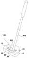
도 1은 본 발명의 일 실시예에 따른 롤러를 갖는 골프 퍼터를 도시한 사시도,
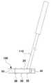
도 2는 본 발명의 일 실시예에 따른 롤러를 갖는 골프 퍼터를 도시한 정면도,
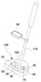
도 3은 본 발명의 다른 실시예에 따른 롤러를 갖는 골프 퍼터를 도시한 사시도,
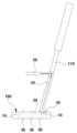
도 4는 본 발명의 다른 실시예에 따른 롤러를 갖는 골프 퍼터를 도시한 정면도.1 is a perspective view showing a golf putter having a roller according to an embodiment of the present invention;
2 is a front view showing a golf putter having a roller according to an embodiment of the present invention;
3 is a perspective view showing a golf putter having a roller according to another embodiment of the present invention;
Figure 4 is a front view showing a golf putter having a roller according to another embodiment of the present invention.
이하, 본 발명의 바람직한 실시예를 첨부도면을 참조로 상세하게 설명하기로 한다.Hereinafter, preferred embodiments of the present invention will be described in detail with reference to the accompanying drawings.
상기한 바와 같이 골퍼의 불안정한 퍼팅 자세에 따라 퍼터의 타격면이 늦게 열리는 경우(타격면이 닫힌 경우), 소위 뒤땅을 치는 퍼팅 에러가 발생할 수 있고, 또한 퍼팅시 퍼터 헤드의 타격면이 일찍 열리거나 닫히는 경우 골프공의 원하는 직진성 및 방향성이 상실될 수 있으므로, 퍼팅시 퍼터 헤드의 타격면 중앙과 골프공의 중앙부위가 일축상에 정확하게 위치되도록 하여 퍼터 헤드의 타격면과 골프공의 타격점이 수평상태를 유지하도록 하는 것이 중요하다.As described above, if the hitting surface of the putter opens late (when the hitting surface is closed) depending on the golfer's unstable putting posture, a so-called putting error may occur, and also, during putting, the hitting surface of the putter head may open early or If it is closed, the desired straightness and direction of the golf ball may be lost. When putting, the center of the hitting surface of the putter head and the central part of the golf ball should be precisely positioned on one axis so that the hitting surface of the putter head and the hitting point of the golf ball are in a horizontal state. It is important to keep
이를 위해, 본 발명은 퍼터의 퍼터 헤드에 복수개의 롤러를 장착하여, 퍼팅시 롤러가 지면에 닿아 구름 운동하도록 함으로써, 롤러가 퍼터 헤드의 퍼팅 궤적을 일정하게 안내해줄 수 있고, 그에 따라 퍼팅시 골프공의 직진성 및 방향성에 대한 정확도 향상에 도움을 줄 수 있도록 한 점에 주안점이 있다.To this end, the present invention mounts a plurality of rollers on the putter head of the putter, so that the rollers come into contact with the ground and perform rolling motion during putting, so that the rollers can guide the putting trajectory of the putter head at a constant level, thereby providing a golf course during putting. There is a focus on one point to help improve the accuracy of the straightness and direction of the ball.
첨부한 도 1은 본 발명의 일 실시예에 따른 롤러를 갖는 골프 퍼터를 도시한 사시도이고, 도 2는 본 발명의 일 실시예에 따른 롤러를 갖는 골프 퍼터를 도시한 정면도이다.1 is a perspective view showing a golf putter having a roller according to an embodiment of the present invention, and FIG. 2 is a front view showing a golf putter having a roller according to an embodiment of the present invention.
도 1 및 도 2에 도시된 바와 같이, 골프 퍼터의 퍼터 헤드(100)를 직사각 형태의 롤러 장착홀(102)이 상하로 관통 형성된 구조로 구비한다.As shown in FIGS. 1 and 2 , the
예를 들어, 상기 퍼터 헤드(100)에 상하로 관통된 직사각 형태의 롤러 장착홀(102)이 밀링머신 등에 의하여 용이하게 절삭 가공될 수 있다.For example, the rectangular
상기 퍼터 헤드(100)에 형성된 롤러 장착홀(102)의 양측벽면에는 베어링(10)이 장착된다.
이때, 상기 롤러 장착홀(102)의 양측벽면에 장착된 베어링(10)에 회전 가능하게 체결되는 롤러샤프트(20)가 구비되는 바, 이 롤러샤프트(20)에는 3개 이상의 롤러(30)가 퍼팅방향을 향하여 구름 가능하게 등간격으로 장착된다.At this time, a
위와 같이 구비된 롤러샤프트(20) 즉, 3개 이상의 롤러(30)가 장착된 롤러샤프트(20)를 상기 롤러 장착홀(102) 내에 진입시킴과 함께 롤러샤프트(20)의 양단부가 퍼터 헤드(100)의 양측방향으로 향하도록 배열시킨 다음, 롤러샤프트(20)의 양단부를 각각 상기 베어링(10)에 회전 가능하게 체결시키게 된다.The
이때, 상기 3개의 롤러(30)가 장착된 롤러샤프트(20)를 베어링(10)에 체결시키면, 각 롤러(30)의 하단부가 지면에 구름 가능하게 밀착되도록 롤러 장착홀(102)의 하부를 지나서 퍼터 헤드(100)의 저면으로부터 돌출 배열되는 상태가 된다.At this time, when the
이에, 상기 퍼터 헤드(100)의 저면으로부터 돌출된 롤러(30)의 하단부로 인하여 상기 퍼터 헤드(100)의 저면과 지면 간의 간격이 일정하게 유지될 수 있다.Thus, due to the lower end of the
따라서, 초보 골퍼 등에 의한 퍼팅시 상기 롤러(30)가 지면에 닿아 구름 운동할 때, 퍼터 헤드(100)의 저면과 지면 간의 간격이 일정하게 유지되는 상태가 됨으로써, 퍼터 헤드(100)의 타격면과 골프공의 타격점을 수평상태로 유지시킬 수 있다.Therefore, when the
더욱이, 초보 골퍼 등에 의한 퍼팅시 상기 롤러(30)가 지면에 닿아 구름 운동할 때, 퍼터 헤드(100)의 저면과 지면 간의 간격이 일정하게 유지되는 상태가 됨으로써, 퍼터 헤드의 타격면이 일찍 열리는 현상을 방지할 수 있을 뿐만 아니라 퍼터 헤드의 타격면이 닫힘에 따라 소위 뒤땅을 치는 퍼팅 에러를 최소화시킬 수 있다.Moreover, when the
또한, 초보 골퍼 등에 의한 퍼팅시 상기 롤러(30)가 지면에 닿아 구름 운동할 때, 퍼터 헤드(100)의 저면과 지면 간의 간격이 일정하게 유지되는 상태가 됨으로써, 퍼터 헤드(100)의 타격면이 일찍 열리거나 닫히는 것을 방지하여 퍼팅 자세 연습 및 교정에 도움을 줄 수 있고, 퍼팅시 골프공의 직진성 및 방향성에 대한 정확도 향상에 도움을 줄 수 있다.In addition, when the
첨부한 도 3은 본 발명의 다른 실시예에 따른 롤러를 갖는 골프 퍼터를 도시한 사시도이고, 도 4는 본 발명의 다른 실시예에 따른 롤러를 갖는 골프 퍼터를 도시한 정면도이다.3 is a perspective view showing a golf putter having a roller according to another embodiment of the present invention, and FIG. 4 is a front view showing a golf putter having a roller according to another embodiment of the present invention.
본 발명의 다른 실시예는 초보 골퍼 등이 퍼팅을 위한 퍼터의 스윙 속도 조절에 대한 연습 및 교정에 도움을 줄 수 있도록 한 점에 주안점이 있다.Another embodiment of the present invention focuses on helping novice golfers practice and correct swing speed control of a putter for putting.
이를 위해, 도 3 및 도 4에 도시된 바와 같이 상기 퍼터 헤드(100)의 상면 소정 위치에는 롤러(30)의 회전속도를 검출하는 휠 스피드 센서(40)가 장착되고, 상기 퍼터 헤드(100)의 일측부에 연결되는 퍼터샤프트(110)의 상단부에 상기 휠 스피드 센서(40)에서 검출된 롤러의 회전속도를 표시하는 디스플레이(50)가 장착된다.To this end, as shown in FIGS. 3 and 4, a
이때, 상기 휠 스피드 센서(40)의 출력배선(42)이 상기 퍼터샤프트(110)의 내부에 삽입되어 상기 디스플레이(50)에 신호 전달 가능하게 연결되고, 상기 디스플레이(50)에는 휠 스피드 센서의 출력값을 수치화된 속도(m/s)로 연산하는 제어기판이 내장될 수 있다.At this time, the
따라서, 초보 골퍼 등에 의한 퍼팅시 상기 롤러(30)가 지면에 닿아 구름 운동할 때, 상기 휠 스피드 센서(40)에서 롤러(30)의 속도를 검출하고, 검출된 속도가 상기 디스플레이(50)에 표시되도록 함으로써, 골퍼가 디스플레이(50)에 표시되는 속도를 보고 본인의 퍼팅 스윙 속도를 쉽게 인지할 수 있다.Therefore, when the
이와 같이, 퍼팅시 상기 롤러(30)가 지면에 닿아 구름 운동할 때, 롤러(30)의 속도를 휠 스피드 센서(40)로 측정하여 디스플레이(50)를 통해 실시간으로 골퍼에게 보여줄 수 있도록 함으로써, 퍼팅을 위한 퍼터의 스윙 속도 조절에 대한 연습 및 교정에 도움을 줄 수 있다.In this way, when the
한편, 롤러샤프트(20)에는 금속표면의 내마모성, 내오염성을 향상하기 위하여 도포층이 형성될 수 있다.Meanwhile, a coating layer may be formed on the
이러한 도포층의 도포재료는 디시클로펜타디엔 다이옥사이드 20중량%, 모노에탄올아민 17중량%, 하프늄 13중량%, 유기산마그네슘 15중량%, 산화티타늄(TiO2) 8중량%, 산화알루미늄(Al2O3) 9중량%, 논플루오로케미칼액티브 18중량%로 구성되며, 코팅두께는 8㎛로 형성할 수 있다.The coating material of this coating layer is 20% by weight of dicyclopentadiene dioxide, 17% by weight of monoethanolamine, 13% by weight of hafnium, 15% by weight of organic acid magnesium, 8% by weight of titanium oxide (TiO2 ), aluminum oxide (Al2 O3 ) It is composed of 9% by weight and 18% by weight of non-fluorochemical active, and the coating thickness can be formed to 8㎛.
디시클로펜타디엔 다이옥사이드, 모노에탄올아민은 부식 방지 및 내오염성, 변색 방지 등의 역할을 하고, 하프늄은 내마모성, 내부식성이 있는 전이 금속원소로서 뛰어난 방수성, 내식성 등을 갖도록 역할을 한다.Dicyclopentadiene dioxide and monoethanolamine serve to prevent corrosion, stain resistance and discoloration, and hafnium is a transition metal element with wear resistance and corrosion resistance, and plays a role to have excellent waterproofness and corrosion resistance.
유기산마그네슘은 코팅피막의 표면에 내알칼리성과 습동성 등을 부여하는 역할을 하고, 논플루오로케미칼액티브는 계면활성 역할을 하며, 산화티타늄, 산화알루미늄은 내화도 및 화학적 안정성 등을 목적으로 첨가된다.Organic acid magnesium serves to impart alkali resistance and wettability to the surface of the coating film, non-fluorochemical active serves as a surface activity, and titanium oxide and aluminum oxide are added for the purpose of fire resistance and chemical stability.
상기 구성 성분의 비율 및 코팅 두께를 상기와 같이 수치 한정한 이유는, 본 발명자가 수차례 실패를 거듭하면서 시험결과를 통해 분석한 결과, 상기 비율에서 최적의 내마모성, 내오염성 향상 효과를 나타내었다.The reason for limiting the ratio of the components and the coating thickness as described above is that the present inventors have repeatedly failed several times and analyzed the test results. As a result, the above ratio showed the optimal abrasion resistance and stain resistance improvement effect.
또한, 퍼터 헤드(100)에는 오염물질의 부착방지 및 제거를 효과적으로 달성할 수 있도록 오염 방지 도포용 조성물로 이루어진 오염방지도포층이 도포될 수 있다.In addition, an antifouling coating layer made of an antifouling coating composition may be applied to the
상기 오염 방지 도포용 조성물은 4A제올라이트 및 에틸셀루솔브가 1:0.01 ~ 1:2 몰비로 포함되어 있고, 4A제올라이트 및 에틸셀루솔브의 총함량은 전체 수용액에 대해 1 ~10 중량%이다.The antifouling coating composition contains 4A zeolite and Ethyl Cellusolve in a molar ratio of 1:0.01 to 1:2, and the total content of 4A zeolite and Ethyl Cellusolve is 1 to 10% by weight based on the total aqueous solution.
상기 4A제올라이트 및 에틸셀루솔브는 몰비로서 1:0.01 ~ 1:2가 바람직한 바, 몰비가 상기 범위를 벗어나는 경우에는 퍼터 헤드(100)의 도포성이 저하되거나 도포 후에 표면의 수분흡착이 증가하여 도포막이 제거되는 문제점이 있다.The 4A zeolite and Ethyl Cellusolve are preferably 1:0.01 to 1:2 as a molar ratio. If the molar ratio is out of the above range, the applicability of the
상기 4A제올라이트 및 에틸셀루솔브는 전체 조성물 수용액 중 1 ~ 10 중량%가 바람직한 바, 1 중량% 미만이면 퍼터 헤드(100)의 도포성이 저하되는 문제점이 있고, 10 중량%를 초과하면 도포막 두께의 증가로 인한 결정석출이 발생하기 쉽다.The 4A zeolite and ethylcellusolve are preferably 1 to 10% by weight of the total aqueous solution of the composition. If the content is less than 1% by weight, the coating property of the
한편, 본 오염방지도포용 조성물을 퍼터 헤드(100)에 도포하는 방법으로는 스프레이법에 의해 도포하는 것이 바람직하다. 또한, 퍼터 헤드(100)의 최종 도포막 두께는 800 ~ 2400Å이 바람직하며, 보다 바람직하게는 900 ~ 2000Å이다. 상기 도포막의 두께가 800 Å미만이면 고온 열처리의 경우에 열화되는 문제점이 있고, 2400 Å을 초과하면 도포 표면의 결정석출이 발생하기 쉬운 단점이 있다.On the other hand, as a method of applying the present antifouling coating composition to the
또한, 본 오염 방지 도포용 조성물은 4A제올라이트 0.1 몰 및 에틸셀루솔브 0.05몰을 증류수 1000 ㎖에 첨가한 다음 교반하여 제조될 수 있다.In addition, this antifouling coating composition can be prepared by adding 0.1 mole of 4A zeolite and 0.05 mole of Ethyl Cellusolve to 1000 ml of distilled water and then stirring.
상기 구성 성분의 비율 및 도포막 두께를 상기와 같이 수치 한정한 이유는, 본 발명자가 수차례 실패를 거듭하면서 시험결과를 통해 분석한 결과, 상기 비율에서 최적의 오염방지 도포 효과를 나타내었다.The reason why the ratio of the constituent components and the thickness of the coating film were numerically limited as described above was that the present inventors showed the optimal antifouling coating effect at the ratio as a result of analyzing the test results while repeating several failures.
그리고, 롤러(30)는 고무 재질로 이루어질 수 있으며, 이러한 롤러(30)의 원료 함량비는 고무 62중량%, 징크 디메틸디치오카바메이트 8중량%, 바리움스테아레이트 8중량%, 카아본블랙 11중량%, 3C(N-PHENYL-N'-ISOPROPYL- P-PHENYLENEDIAMINE) 5중량%, 디페닐구아니딘 6중량% 를 혼합한다.In addition, the
징크 디메틸디치오카바메이트는 가황촉진 향상 등을 위해 첨가되며, 바리움스테아레이트는 연화제 역할을 위해 첨가되고, 카아본블랙은 내마모성, 열전도성 등을 증대하거나 향상시키기 위해 첨가된다.Zinc dimethyldithiocarbamate is added to improve vulcanization acceleration, barium stearate is added to act as a softener, and carbon black is added to increase or improve wear resistance, thermal conductivity, and the like.
3C (N-PHENYL-N'-ISOPROPYL- P-PHENYLENEDIAMINE)는 산화방지제로 첨가되며, 디페닐구아니딘는 촉진제 등의 역할을 위해 첨가된다.3C (N-PHENYL-N'-ISOPROPYL-P-PHENYLENEDIAMINE) is added as an antioxidant, and diphenylguanidine is added to act as an accelerator.
따라서 본 발명은 롤러(30)의 탄성, 인성 및 강성이 증대되므로 내구성이 향상되며, 이에 따라 롤러(30)의 수명이 증대된다.Therefore, according to the present invention, elasticity, toughness, and rigidity of the
고무재질의 인장강도는 158Kg/㎠, 신율 620%로 형성된다. The rubber material has a tensile strength of 158Kg/cm2 and an elongation of 620%.
고무재질 구성 물질 및 구성 성분을 한정하고 혼합 비율의 수치 등을 한정한 이유는, 본 발명자가 수차례 실패를 거듭하면서 시험 결과를 통해 분석한 결과, 상기 구성 성분 및 수치 한정 비율에서 최적의 효과를 나타내었다.The reason for limiting the components and components of the rubber material and limiting the numerical values of the mixing ratio is that, as a result of the inventor's analysis through test results while repeating several failures, the optimal effect in the constituent components and numerically limited ratios showed up
또한, 퍼터샤프트(110)와 퍼터샤프트(110) 상단의 손잡이에는 접착향상제가 도포될 수 있다.In addition, an adhesion enhancer may be applied to the
접착향상제는 물 63중량부, 비닐트리메톡시실란 8중량부, 2-스티릴이미디졸 11중량부, 술포숙신산 나트륨 13중량부, 과황산암모늄 3중량부, 중탄산나트륨 2중량부를 포함하여 이루어질 수 있다.The adhesion enhancer comprises 63 parts by weight of water, 8 parts by weight of vinyltrimethoxysilane, 11 parts by weight of 2-styrylimidizole, 13 parts by weight of sodium sulfosuccinate, 3 parts by weight of ammonium persulfate, and 2 parts by weight of sodium bicarbonate. can
비닐트리메톡시실란은 밀착, 접착성 부여 등을 위해 첨가되고, 2-스티릴이미디졸은 접착성, 경화촉진 등을 향상하기 위해 첨가되며, 술포숙신산 나트륨은 계면활성제의 역할을 하고, 과황산암모늄은 촉매제 역할을 하며, 중탄산나트륨은 완충제 역할을 한다.Vinyltrimethoxysilane is added for adhesion and imparting adhesiveness, 2-styrylimidisol is added to improve adhesion and curing acceleration, etc., sodium sulfosuccinate serves as a surfactant, and Ammonium sulfate acts as a catalyst and sodium bicarbonate acts as a buffer.
상기와 같이 구성 물질 및 구성 성분을 한정하고 혼합 비율의 수치를 한정한 이유는, 본 발명자가 수차례 실패를 거듭하면서 시험 결과를 통해 분석한 결과, 상기 구성 성분 및 수치 한정 비율에서 최적의 효과를 나타내었다.The reason for limiting the constituent materials and components and limiting the numerical values of the mixing ratios as described above is that, as a result of the present inventors' analysis through test results while repeating several failures, the optimal effect in the constituent components and numerically limited ratios was obtained. showed up
10 : 베어링
20 : 롤러샤프트
30 : 롤러
40 : 휠 스피드 센서
42 : 출력배선
50 : 디스플레이
100 : 퍼터 헤드
102 : 롤러 장착홀
110 : 퍼터샤프트10: bearing
20: roller shaft
30: roller
40: wheel speed sensor
42: output wiring
50: display
100: putter head
102: roller mounting hole
110: putter shaft
Claims (2)
Translated fromKorean상기 롤러 장착홀(102)의 양측벽면에 장착되는 베어링(10);
상기 베어링(10)에 양단부가 회전 가능하게 체결되는 롤러샤프트(20); 및
상기 롤러샤프트(20)에 퍼팅방향을 향하여 구름 가능하게 등간격으로 장착되는 3개 이상의 롤러(30)를 포함하고;
상기 롤러(30)의 하단부가 지면에 구름 가능하게 밀착되도록 롤러 장착홀(102)의 하부를 지나서 퍼터 헤드(100)의 저면으로부터 돌출 배열되며;
상기 퍼터 헤드(100)의 상면 소정 위치에는 롤러(30)의 회전속도를 검출하는 휠 스피드 센서(40)가 장착되고, 상기 퍼터 헤드(100)의 일측부에 연결되는 퍼터샤프트(110)의 상단부에는 상기 휠 스피드 센서(40)에서 검출된 롤러의 회전속도를 표시하는 디스플레이(50)가 장착되며, 상기 휠 스피드 센서(40)의 출력배선(42)이 상기 퍼터샤프트(110)의 내부에 삽입되어 상기 디스플레이(50)에 신호 전달 가능하게 연결되고, 디스플레이(50)에는 휠 스피드 센서(40)의 출력값을 수치화된 속도(m/s)로 연산하는 제어기판이 내장되며,
롤러샤프트(20)에는 도포층이 형성되되, 상기 도포층의 도포재료는 디시클로펜타디엔 다이옥사이드 20중량%, 모노에탄올아민 17중량%, 하프늄 13중량%, 유기산마그네슘 15중량%, 산화티타늄(TiO2) 8중량%, 산화알루미늄(Al2O3) 9중량%, 논플루오로케미칼액티브 18중량%로 구성되며, 코팅두께는 8㎛로 형성되고;
퍼터 헤드(100)에는 오염 방지 도포용 조성물로 이루어진 오염방지도포층이 도포되되, 상기 오염 방지 도포용 조성물은 4A제올라이트 및 에틸셀루솔브가 1:0.01 ~ 1:2 몰비로 포함되어 있으며;
롤러(30)의 원료 함량비는 고무 62중량%, 징크 디메틸디치오카바메이트 8중량%, 바리움스테아레이트 8중량%, 카아본블랙 11중량%, 3C(N-PHENYL-N'-ISOPROPYL- P-PHENYLENEDIAMINE) 5중량%, 디페닐구아니딘 6중량% 를 혼합하여서 이루어지고;
퍼터샤프트(110)와 퍼터샤프트(110) 상단의 손잡이에는 접착향상제가 도포되되, 상기 접착향상제는 물 63중량부, 비닐트리메톡시실란 8중량부, 2-스티릴이미디졸 11중량부, 술포숙신산 나트륨 13중량부, 과황산암모늄 3중량부, 중탄산나트륨 2중량부를 포함하여 이루어지는 것을 특징으로 하는 롤러를 갖는 골프 퍼터.A putter head 100 through which roller mounting holes 102 vertically pass through;
Bearings 10 mounted on both side walls of the roller mounting hole 102;
a roller shaft 20 having both ends rotatably fastened to the bearing 10; and
It includes three or more rollers 30 mounted on the roller shaft 20 at equal intervals so as to roll toward the putting direction;
The lower end of the roller 30 protrudes from the lower surface of the putter head 100 through the lower part of the roller mounting hole 102 so that it can be rolled on the ground;
A wheel speed sensor 40 for detecting the rotational speed of the roller 30 is mounted at a predetermined position on the upper surface of the putter head 100, and the upper end of the putter shaft 110 connected to one side of the putter head 100. A display 50 displaying the rotational speed of the roller detected by the wheel speed sensor 40 is mounted, and the output wire 42 of the wheel speed sensor 40 is inserted into the putter shaft 110. is connected to the display 50 to enable signal transmission, and the display 50 has a built-in control board that calculates the output value of the wheel speed sensor 40 as a digitized speed (m / s),
A coating layer is formed on the roller shaft 20, and the coating materials of the coating layer include 20% by weight of dicyclopentadiene dioxide, 17% by weight of monoethanolamine, 13% by weight of hafnium, 15% by weight of magnesium organic acid, and titanium oxide (TiO2 ) 8% by weight, 9% by weight of aluminum oxide (Al2 O3 ), and 18% by weight of non-fluorochemical active, and the coating thickness is 8㎛;
An antifouling coating layer made of an antifouling coating composition is applied to the putter head 100, and the antifouling coating composition contains 4A zeolite and Ethyl Cellusolve in a molar ratio of 1:0.01 to 1:2;
The raw material content ratio of the roller 30 is 62% by weight of rubber, 8% by weight of zinc dimethyl dithiocarbamate, 8% by weight of barium stearate, 11% by weight of carbon black, 3C (N-PHENYL-N'-ISOPROPYL-P -PHENYLENEDIAMINE) 5% by weight and 6% by weight of diphenylguanidine;
An adhesion enhancer is applied to the putter shaft 110 and the handle at the top of the putter shaft 110, and the adhesion enhancer includes 63 parts by weight of water, 8 parts by weight of vinyltrimethoxysilane, 11 parts by weight of 2-styrylimidisol, A golf putter with a roller comprising 13 parts by weight of sodium sulfosuccinate, 3 parts by weight of ammonium persulfate, and 2 parts by weight of sodium bicarbonate.
Priority Applications (1)
| Application Number | Priority Date | Filing Date | Title |
|---|---|---|---|
| KR1020220027881AKR102504857B1 (en) | 2022-03-04 | 2022-03-04 | Putter for golf having roller |
Applications Claiming Priority (1)
| Application Number | Priority Date | Filing Date | Title |
|---|---|---|---|
| KR1020220027881AKR102504857B1 (en) | 2022-03-04 | 2022-03-04 | Putter for golf having roller |
Publications (1)
| Publication Number | Publication Date |
|---|---|
| KR102504857B1true KR102504857B1 (en) | 2023-02-28 |
Family
ID=85327040
Family Applications (1)
| Application Number | Title | Priority Date | Filing Date |
|---|---|---|---|
| KR1020220027881AActiveKR102504857B1 (en) | 2022-03-04 | 2022-03-04 | Putter for golf having roller |
Country Status (1)
| Country | Link |
|---|---|
| KR (1) | KR102504857B1 (en) |
Citations (4)
| Publication number | Priority date | Publication date | Assignee | Title |
|---|---|---|---|---|
| US4535992A (en)* | 1983-09-01 | 1985-08-20 | Slagle Frederick A | Training device for putting golf balls |
| JPH09239079A (en)* | 1996-03-12 | 1997-09-16 | Haruo Nakao | Putter for golf |
| KR20190000610U (en) | 2017-08-31 | 2019-03-08 | 노영범 | Direction setting aid for putt |
| KR102265374B1 (en)* | 2019-05-28 | 2021-06-17 | (주)아이엔에스 | Putting information providing device with aiming function |
- 2022
- 2022-03-04KRKR1020220027881Apatent/KR102504857B1/enactiveActive
Patent Citations (4)
| Publication number | Priority date | Publication date | Assignee | Title |
|---|---|---|---|---|
| US4535992A (en)* | 1983-09-01 | 1985-08-20 | Slagle Frederick A | Training device for putting golf balls |
| JPH09239079A (en)* | 1996-03-12 | 1997-09-16 | Haruo Nakao | Putter for golf |
| KR20190000610U (en) | 2017-08-31 | 2019-03-08 | 노영범 | Direction setting aid for putt |
| KR102265374B1 (en)* | 2019-05-28 | 2021-06-17 | (주)아이엔에스 | Putting information providing device with aiming function |
Similar Documents
| Publication | Publication Date | Title |
|---|---|---|
| US8235830B2 (en) | Visual swing indicator golf club head | |
| US20010005820A1 (en) | Method for matching golfers with a driver and ball | |
| US6520865B1 (en) | Golf club putter head design | |
| US8905867B2 (en) | Batting tee system for bat-and-ball games | |
| JPH04241886A (en) | Aid and training device for golf putting | |
| US7416492B2 (en) | Golf clubface swing trainer | |
| KR102504857B1 (en) | Putter for golf having roller | |
| KR101046790B1 (en) | Putting Guide Golf Ball | |
| US3073602A (en) | Training device | |
| US20190255401A1 (en) | Putting training device | |
| KR200446609Y1 (en) | Golf putter | |
| US6923737B1 (en) | Baseball swing training apparatus | |
| US9314684B2 (en) | Putting training aid | |
| US20020177486A1 (en) | Putter bubble | |
| MacKenzie et al. | Evaluation of Near Versus Far Target Visual Focus Strategies With Breaking Putts. | |
| KR20230161720A (en) | Portable Putting Training Device | |
| JP3011144U (en) | Practice golf club | |
| JP2599509Y2 (en) | Golf club head | |
| KR200317655Y1 (en) | Golf club | |
| KR200366319Y1 (en) | Putting correction device for golf club | |
| KR20130032775A (en) | Equipped with roller putter head | |
| KR20090067243A (en) | Golf putters that provide putting guides | |
| WO2006093988A1 (en) | Golf swing training device | |
| KR20080080771A (en) | Golf putter | |
| KR200310728Y1 (en) | Golf club having shaft combined with the center of gravity of head |
Legal Events
| Date | Code | Title | Description |
|---|---|---|---|
| PA0109 | Patent application | Patent event code:PA01091R01D Comment text:Patent Application Patent event date:20220304 | |
| PA0201 | Request for examination | ||
| PA0302 | Request for accelerated examination | Patent event date:20220310 Patent event code:PA03022R01D Comment text:Request for Accelerated Examination Patent event date:20220304 Patent event code:PA03021R01I Comment text:Patent Application | |
| PE0902 | Notice of grounds for rejection | Comment text:Notification of reason for refusal Patent event date:20221121 Patent event code:PE09021S01D | |
| PE0701 | Decision of registration | Patent event code:PE07011S01D Comment text:Decision to Grant Registration Patent event date:20230222 | |
| PR0701 | Registration of establishment | Comment text:Registration of Establishment Patent event date:20230223 Patent event code:PR07011E01D | |
| PR1002 | Payment of registration fee | Payment date:20230223 End annual number:3 Start annual number:1 | |
| PG1601 | Publication of registration |