KR102500690B1 - Battery status based charging control method and appratus thereof - Google Patents
Battery status based charging control method and appratus thereofDownload PDFInfo
- Publication number
- KR102500690B1 KR102500690B1KR1020170119353AKR20170119353AKR102500690B1KR 102500690 B1KR102500690 B1KR 102500690B1KR 1020170119353 AKR1020170119353 AKR 1020170119353AKR 20170119353 AKR20170119353 AKR 20170119353AKR 102500690 B1KR102500690 B1KR 102500690B1
- Authority
- KR
- South Korea
- Prior art keywords
- battery
- state
- voltage
- charging
- electronic device
- Prior art date
- Legal status (The legal status is an assumption and is not a legal conclusion. Google has not performed a legal analysis and makes no representation as to the accuracy of the status listed.)
- Active
Links
- 238000007600chargingMethods0.000titleclaimsabstractdescription338
- 238000000034methodMethods0.000titledescription15
- 230000002159abnormal effectEffects0.000claimsdescription103
- 230000008859changeEffects0.000claimsdescription74
- 238000004891communicationMethods0.000description33
- 238000010277constant-current chargingMethods0.000description24
- 230000000875corresponding effectEffects0.000description22
- 238000010280constant potential chargingMethods0.000description21
- 230000006870functionEffects0.000description14
- 238000012549trainingMethods0.000description11
- 239000000446fuelSubstances0.000description7
- 230000000007visual effectEffects0.000description6
- 230000001276controlling effectEffects0.000description5
- 238000010586diagramMethods0.000description5
- 238000005516engineering processMethods0.000description5
- 238000012545processingMethods0.000description5
- 230000004044responseEffects0.000description5
- 238000006243chemical reactionMethods0.000description4
- 238000004590computer programMethods0.000description4
- 230000006866deteriorationEffects0.000description4
- 230000014509gene expressionEffects0.000description4
- 230000007423decreaseEffects0.000description3
- 238000007599dischargingMethods0.000description3
- 238000013021overheatingMethods0.000description3
- 230000005856abnormalityEffects0.000description2
- 230000009471actionEffects0.000description2
- 230000006399behaviorEffects0.000description2
- 238000010281constant-current constant-voltage chargingMethods0.000description2
- 238000012986modificationMethods0.000description2
- 230000004048modificationEffects0.000description2
- 230000002093peripheral effectEffects0.000description2
- 230000001133accelerationEffects0.000description1
- 230000000903blocking effectEffects0.000description1
- 238000004364calculation methodMethods0.000description1
- 230000015556catabolic processEffects0.000description1
- 230000010267cellular communicationEffects0.000description1
- 230000001413cellular effectEffects0.000description1
- 238000006731degradation reactionMethods0.000description1
- 238000001514detection methodMethods0.000description1
- 238000011161developmentMethods0.000description1
- 230000000694effectsEffects0.000description1
- 230000007613environmental effectEffects0.000description1
- 230000020169heat generationEffects0.000description1
- 238000009434installationMethods0.000description1
- 230000010354integrationEffects0.000description1
- 230000003155kinesthetic effectEffects0.000description1
- 238000005259measurementMethods0.000description1
- 230000005236sound signalEffects0.000description1
- 230000000638stimulationEffects0.000description1
- 230000008961swellingEffects0.000description1
- 230000007704transitionEffects0.000description1
Images


Classifications
- H—ELECTRICITY
- H02—GENERATION; CONVERSION OR DISTRIBUTION OF ELECTRIC POWER
- H02J—CIRCUIT ARRANGEMENTS OR SYSTEMS FOR SUPPLYING OR DISTRIBUTING ELECTRIC POWER; SYSTEMS FOR STORING ELECTRIC ENERGY
- H02J7/00—Circuit arrangements for charging or depolarising batteries or for supplying loads from batteries
- H02J7/007—Regulation of charging or discharging current or voltage
- H02J7/00712—Regulation of charging or discharging current or voltage the cycle being controlled or terminated in response to electric parameters
- H02J7/007182—Regulation of charging or discharging current or voltage the cycle being controlled or terminated in response to electric parameters in response to battery voltage
- G—PHYSICS
- G01—MEASURING; TESTING
- G01R—MEASURING ELECTRIC VARIABLES; MEASURING MAGNETIC VARIABLES
- G01R31/00—Arrangements for testing electric properties; Arrangements for locating electric faults; Arrangements for electrical testing characterised by what is being tested not provided for elsewhere
- G01R31/36—Arrangements for testing, measuring or monitoring the electrical condition of accumulators or electric batteries, e.g. capacity or state of charge [SoC]
- G01R31/382—Arrangements for monitoring battery or accumulator variables, e.g. SoC
- G01R31/3835—Arrangements for monitoring battery or accumulator variables, e.g. SoC involving only voltage measurements
- G—PHYSICS
- G01—MEASURING; TESTING
- G01R—MEASURING ELECTRIC VARIABLES; MEASURING MAGNETIC VARIABLES
- G01R31/00—Arrangements for testing electric properties; Arrangements for locating electric faults; Arrangements for electrical testing characterised by what is being tested not provided for elsewhere
- G01R31/36—Arrangements for testing, measuring or monitoring the electrical condition of accumulators or electric batteries, e.g. capacity or state of charge [SoC]
- G01R31/392—Determining battery ageing or deterioration, e.g. state of health
- H—ELECTRICITY
- H02—GENERATION; CONVERSION OR DISTRIBUTION OF ELECTRIC POWER
- H02J—CIRCUIT ARRANGEMENTS OR SYSTEMS FOR SUPPLYING OR DISTRIBUTING ELECTRIC POWER; SYSTEMS FOR STORING ELECTRIC ENERGY
- H02J7/00—Circuit arrangements for charging or depolarising batteries or for supplying loads from batteries
- H02J7/0029—Circuit arrangements for charging or depolarising batteries or for supplying loads from batteries with safety or protection devices or circuits
- H—ELECTRICITY
- H02—GENERATION; CONVERSION OR DISTRIBUTION OF ELECTRIC POWER
- H02J—CIRCUIT ARRANGEMENTS OR SYSTEMS FOR SUPPLYING OR DISTRIBUTING ELECTRIC POWER; SYSTEMS FOR STORING ELECTRIC ENERGY
- H02J7/00—Circuit arrangements for charging or depolarising batteries or for supplying loads from batteries
- H02J7/0047—Circuit arrangements for charging or depolarising batteries or for supplying loads from batteries with monitoring or indicating devices or circuits
- H02J7/0048—Detection of remaining charge capacity or state of charge [SOC]
- H—ELECTRICITY
- H02—GENERATION; CONVERSION OR DISTRIBUTION OF ELECTRIC POWER
- H02J—CIRCUIT ARRANGEMENTS OR SYSTEMS FOR SUPPLYING OR DISTRIBUTING ELECTRIC POWER; SYSTEMS FOR STORING ELECTRIC ENERGY
- H02J7/00—Circuit arrangements for charging or depolarising batteries or for supplying loads from batteries
- H02J7/007—Regulation of charging or discharging current or voltage
- H02J7/00712—Regulation of charging or discharging current or voltage the cycle being controlled or terminated in response to electric parameters
- H02J7/00714—Regulation of charging or discharging current or voltage the cycle being controlled or terminated in response to electric parameters in response to battery charging or discharging current
- H02J7/00718—Regulation of charging or discharging current or voltage the cycle being controlled or terminated in response to electric parameters in response to battery charging or discharging current in response to charge current gradient
- H—ELECTRICITY
- H04—ELECTRIC COMMUNICATION TECHNIQUE
- H04M—TELEPHONIC COMMUNICATION
- H04M1/00—Substation equipment, e.g. for use by subscribers
- H04M1/02—Constructional features of telephone sets
- H04M1/0202—Portable telephone sets, e.g. cordless phones, mobile phones or bar type handsets
- H04M1/026—Details of the structure or mounting of specific components
- H04M1/0262—Details of the structure or mounting of specific components for a battery compartment
- H—ELECTRICITY
- H04—ELECTRIC COMMUNICATION TECHNIQUE
- H04M—TELEPHONIC COMMUNICATION
- H04M1/00—Substation equipment, e.g. for use by subscribers
- H04M1/72—Mobile telephones; Cordless telephones, i.e. devices for establishing wireless links to base stations without route selection
- H04M1/724—User interfaces specially adapted for cordless or mobile telephones
- H04M1/72403—User interfaces specially adapted for cordless or mobile telephones with means for local support of applications that increase the functionality
- H04M1/72409—User interfaces specially adapted for cordless or mobile telephones with means for local support of applications that increase the functionality by interfacing with external accessories
- H—ELECTRICITY
- H04—ELECTRIC COMMUNICATION TECHNIQUE
- H04M—TELEPHONIC COMMUNICATION
- H04M1/00—Substation equipment, e.g. for use by subscribers
- H04M1/72—Mobile telephones; Cordless telephones, i.e. devices for establishing wireless links to base stations without route selection
- H04M1/724—User interfaces specially adapted for cordless or mobile telephones
- H04M1/72448—User interfaces specially adapted for cordless or mobile telephones with means for adapting the functionality of the device according to specific conditions
- H04M1/72454—User interfaces specially adapted for cordless or mobile telephones with means for adapting the functionality of the device according to specific conditions according to context-related or environment-related conditions
- H—ELECTRICITY
- H02—GENERATION; CONVERSION OR DISTRIBUTION OF ELECTRIC POWER
- H02J—CIRCUIT ARRANGEMENTS OR SYSTEMS FOR SUPPLYING OR DISTRIBUTING ELECTRIC POWER; SYSTEMS FOR STORING ELECTRIC ENERGY
- H02J7/00—Circuit arrangements for charging or depolarising batteries or for supplying loads from batteries
- H02J7/007—Regulation of charging or discharging current or voltage
- H02J7/00712—Regulation of charging or discharging current or voltage the cycle being controlled or terminated in response to electric parameters
- H02J7/007182—Regulation of charging or discharging current or voltage the cycle being controlled or terminated in response to electric parameters in response to battery voltage
- H02J7/007184—Regulation of charging or discharging current or voltage the cycle being controlled or terminated in response to electric parameters in response to battery voltage in response to battery voltage gradient
Landscapes
- Engineering & Computer Science (AREA)
- Power Engineering (AREA)
- Physics & Mathematics (AREA)
- General Physics & Mathematics (AREA)
- Signal Processing (AREA)
- Human Computer Interaction (AREA)
- Computer Networks & Wireless Communication (AREA)
- Environmental & Geological Engineering (AREA)
- Charge And Discharge Circuits For Batteries Or The Like (AREA)
- Secondary Cells (AREA)
Abstract
Translated fromKoreanDescription
Translated fromKorean본 문서에서 개시되는 실시예들은, 전자 장치의 외부 전력 소스로부터 수신되는 전력을 이용하여 전자 장치에 포함된 배터리(battery)를 충전하는 기술과 관련된다.Embodiments disclosed in this document relate to a technology for charging a battery included in an electronic device using power received from an external power source of the electronic device.
전자 기술의 발달에 힘입어 다양한 유형의 전자 제품들이 개발 및 보급되고 있다. 특히, 최근에는 스마트폰(smart phone), 태블릿 PC(tablet personal computer) 등과 같은 휴대용 전자 장치의 보급이 확대되고 있다.Thanks to the development of electronic technology, various types of electronic products are being developed and supplied. In particular, in recent years, portable electronic devices such as smart phones and tablet PCs (tablet personal computers) have been increasingly popular.
일반적으로, 휴대용 전자 장치는 전자 장치에 내장되거나 탈착가능한 배터리를 전력 공급원으로 사용하고 있다. 배터리의 용량을 증가시키기 위한 기술이 개발되고 있으나 배터리의 용량은 한정적이며 사용자는 휴대용 전자 장치의 배터리의 잔량이 부족한 경우에는 충전 장치를 이용하여 배터리를 충전할 필요가 있다.In general, a portable electronic device uses a battery built in or removable from the electronic device as a power source. A technology for increasing the capacity of the battery is being developed, but the capacity of the battery is limited, and the user needs to charge the battery using a charging device when the remaining battery of the portable electronic device is insufficient.
스마트폰과 같이 배터리를 이용하는 전자 장치는 충전 장치를 이용하여 배터리를 충전할 수 있다. 예를 들어, 충전 장치는 전자 장치의 외부에 위치되고 커넥터를 통하여 전자 장치에 전력을 공급할 수 있다. 또한, 전자 장치는 배터리의 전압에 기반하여 충전을 제어할 수도 있다. 그러나, 예를 들어, 커넥터가 불완전하게 삽입되는 경우, 정확하지 않은 배터리 전압이 측정될 수도 있다. 이 경우, 전자 장치는 정확하지 않은 배터리 전압에 기반하여 충전을 제어할 수도 있다. 따라서, 불완전 충전, 충전 지연, 및/또는 전자 장치의 과열이 발생될 수도 있다. 또한, 배터리의 충전과 방전의 반복에 따라서, 배터리의 충전 및 방전 특성이 변경될 수 있다. 이 경우, 지정된 배터리 충전 제어 파라미터들은 배터리의 현재 특성에 대응하지 않을 수 있다.An electronic device using a battery, such as a smart phone, may charge the battery using a charging device. For example, the charging device may be located outside the electronic device and supply power to the electronic device through a connector. Also, the electronic device may control charging based on the voltage of the battery. However, inaccurate battery voltage may be measured, for example, if the connector is inserted incompletely. In this case, the electronic device may control charging based on an inaccurate battery voltage. Thus, incomplete charging, charging delay, and/or overheating of the electronic device may occur. In addition, charging and discharging characteristics of the battery may be changed according to repeated charging and discharging of the battery. In this case, the specified battery charging control parameters may not correspond to the current characteristics of the battery.
기존의 충전 방법에 있어서, 전자 장치는 단순히 배터리의 전압에 기반하여 충전을 제어할 수 있다. 예를 들어, 배터리의 전압에 기반하여 정전류(constant current, CC) 충전과 정전압(constant voltage, CV) 충전이 선택적으로 수행될 수 있다. 그러나, 상술한 바와 같은 비-이상적 충전 상황에 있어서, 배터리 전압에 기반한 충전 제어로는 불완전 충전, 충전 지연, 및/또는 전자 장치의 과열과 같은 문제점들이 해결될 수 없다.In the existing charging method, the electronic device may simply control charging based on the voltage of the battery. For example, constant current (CC) charging and constant voltage (CV) charging may be selectively performed based on the voltage of the battery. However, in the non-ideal charging situation as described above, problems such as incomplete charging, charging delay, and/or overheating of the electronic device cannot be solved by charging control based on the battery voltage.
본 문서에 개시되는 다양한 실시예들은, 비정상 충전 상황을 감지할 수 있고 배터리 상태에 대응하여 배터리를 충전할 수 있는 장치 및 방법을 제공한다.Various embodiments disclosed in this document provide a device and method capable of detecting an abnormal charging situation and charging a battery in response to a battery state.
본 문서에 개시되는 일 실시예에 따른 전자 장치는, 배터리; 상기 배터리의 전압을 감지하기 위한 제1 감지 회로; 상기 배터리의 전압에 기반하여 상기 배터리를 정전류 상태 또는 정전압 상태로 충전하기 위한 충전 회로; 상기 충전 회로의 출력 전압을 감지하기 위한 제2 감지 회로; 및 프로세서를 포함하고, 상기 프로세서는, 상기 배터리가 상기 정전류 상태로 충전되는 동안, 상기 제1 감지 회로를 이용하여 상기 배터리의 전압 및 상기 제2 감지 회로를 이용하여 상기 출력 전압을 확인하고, 및 적어도 상기 배터리의 전압 및 상기 출력 전압에 기반하여 상기 배터리의 상태를 결정하도록 설정될 수 있다.An electronic device according to an embodiment disclosed in this document includes a battery; a first sensing circuit for sensing the voltage of the battery; a charging circuit for charging the battery into a constant current state or a constant voltage state based on the voltage of the battery; a second sensing circuit for sensing an output voltage of the charging circuit; and a processor, wherein the processor checks a voltage of the battery using the first sensing circuit and the output voltage using the second sensing circuit while the battery is being charged in the constant current state; and It may be configured to determine the state of the battery based on at least the voltage of the battery and the output voltage.
또한, 본 문서에 개시되는 일 실시예에 따른 전자 장치는, 배터리; 상기 배터리의 전압을 감지하기 위한 제1 감지 회로; 상기 배터리의 전압에 기반하여 상기 배터리를 정전류 상태 또는 정전압 상태로 충전하기 위한 충전 회로; 상기 충전 회로의 출력 전압을 감지하기 위한 제2 감지 회로; 디스플레이; 및 프로세서를 포함하고, 상기 프로세서는, 상기 배터리가 상기 정전류 상태로 충전되는 동안, 상기 제1 감지 회로를 이용하여 상기 배터리의 전압 및 상기 제2 감지 회로를 이용하여 상기 출력 전압을 주기적으로 확인하고, 및 상기 배터리의 전압과 상기 출력 전압의 차이, 상기 주기적으로 확인된 상기 배터리의 전압의 변화, 또는 상기 주기적으로 확인된 상기 출력 전압의 변화 중 적어도 하나에 기반하여 상기 배터리의 충전 상태에 대한 정보를 상기 디스플레이를 통하여 제공하도록 설정될 수 있다.또한, 본 문서에 개시되는 일 실시예에 따른 전자 장치는, 배터리; 상기 배터리의 전압을 감지하기 위한 제1 감지 회로; 상기 배터리의 전압에 기반하여 상기 배터리를 정전류 상태 또는 정전압 상태로 충전하기 위한 충전 회로; 상기 충전 회로의 출력 전압을 감지하기 위한 제2 감지 회로; 및 프로세서를 포함하고, 상기 프로세서는, 상기 배터리가 상기 정전류 상태로 충전되는 동안, 상기 제1 감지 회로를 이용하여 상기 배터리의 전압 및 상기 제2 감지 회로를 이용하여 상기 출력 전압을 확인하고, 상기 출력 전압 및 상기 배터리 전압의 차가 지정된 값 이하인 경우, 상기 충전 회로를 이용하여 제1 기준에 따라서 상기 배터리를 상기 정전류 상태 또는 상기 정전압 상태로 충전하고, 및 상기 출력 전압 및 상기 배터리 전압의 차가 상기 지정된 값을 초과하는 경우, 상기 충전 회로를 이용하여 상기 제1 기준과 상이한 상기 제2 기준에 따라서 상기 배터리를 상기 정전류 상태 또는 상기 정전압 상태로 충전하도록 설정되고, 상기 제1 기준은 제1 배터리 전압 값을 포함할 수 있다.In addition, an electronic device according to an embodiment disclosed in this document may include a battery; a first sensing circuit for sensing the voltage of the battery; a charging circuit for charging the battery into a constant current state or a constant voltage state based on the voltage of the battery; a second sensing circuit for sensing an output voltage of the charging circuit; display; and a processor, wherein the processor periodically checks the voltage of the battery using the first sensing circuit and the output voltage using the second sensing circuit while the battery is being charged in the constant current state; Information on the state of charge of the battery based on at least one of the difference between the voltage of the battery and the output voltage, the periodically checked change in the voltage of the battery, or the periodically checked change in the output voltage. may be set to provide through the display. Also, an electronic device according to an embodiment disclosed in this document includes a battery; a first sensing circuit for sensing the voltage of the battery; a charging circuit for charging the battery into a constant current state or a constant voltage state based on the voltage of the battery; a second sensing circuit for sensing an output voltage of the charging circuit; and a processor, wherein the processor checks a voltage of the battery using the first sensing circuit and the output voltage using the second sensing circuit while the battery is being charged in the constant current state; When the difference between the output voltage and the battery voltage is equal to or less than a specified value, the battery is charged in the constant current state or the constant voltage state according to a first criterion using the charging circuit, and the difference between the output voltage and the battery voltage is specified. value, the charging circuit is set to charge the battery in the constant current state or the constant voltage state according to the second criterion different from the first criterion, wherein the first criterion is a first battery voltage value can include
본 문서에 개시되는 실시예들에 따르면, 전자 장치의 비정상 충전을 예방할 수 있다.According to the embodiments disclosed in this document, abnormal charging of an electronic device can be prevented.
또한, 다양한 실시예들에 따르면, 전자 장치의 배터리에 적정한 전력을 공급함으로써 보다 효율적인 충전이 수행될 수 있다.Also, according to various embodiments, more efficient charging may be performed by supplying appropriate power to a battery of an electronic device.
이 외에, 본 문서를 통해 직접적 또는 간접적으로 파악되는 다양한 효과들이 제공될 수 있다.In addition to this, various effects identified directly or indirectly through this document may be provided.
도 1은 일 실시예에 따른 전자 장치의 블록도이다.
도 2는 일 실시예에 따른 전자 장치의 구성을 개략적으로 도시한다.
도 3은 다른 실시예에 따른 전자 장치의 구성을 개략적으로 도시한다.
도 4는 일 예시에 따른 정상 충전 상황에서의 배터리 전압, 충전 전압, 및 충전 전류를 도시한다.
도 5는 일 예시에 따른 정상 충전 상황에서의 충전 상태 및 충전 전류를 도시한다.
도 6a는 일 예시에 따른 정상 충전 상황에서의 배터리 전압 및 시스템 전압을 도시한다.
도 6b는 일 예시에 따른 비정상 충전 상황을 도시한다.
도 6c는 다른 예시에 따른 비정상 충전 상황을 도시한다.
도 7a는 일 예시에 따른 구간별 충전 상태를 도시한다.
도 7b는 다른 예시에 따른 구간별 충전 상태를 도시한다.
도 7c는 또 다른 예시에 따른 구간별 충전 상태를 도시한다.
도 8은 다양한 실시예들에 따른 배터리 상태 결정 방법의 흐름도이다.
도 9는 다양한 실시예들에 따른 충전 제어 방법의 흐름도이다.
도 10은 다양한 실시예들에 따른 배터리 상태 제공 방법의 흐름도이다.
도 11은 다양한 실시예들에 따른 알림 제공 화면을 도시한다.
도 12는 다양한 실시예에 따른 네트워크 환경 내의 전자 장치를 나타낸다.
도 13은 다양한 실시예들에 따른 전자 장치의 전력 관리 모듈 및 배터리에 대한 블럭도이다.
도면의 설명과 관련하여, 동일 또는 유사한 구성요소에 대해서는 동일 또는 유사한 참조 부호가 사용될 수 있다.1 is a block diagram of an electronic device according to an exemplary embodiment.
2 schematically illustrates a configuration of an electronic device according to an exemplary embodiment.
3 schematically illustrates the configuration of an electronic device according to another embodiment.
4 illustrates battery voltage, charging voltage, and charging current in a normal charging situation according to an example.
5 illustrates a charging state and a charging current in a normal charging situation according to an example.
6A shows battery voltage and system voltage in a normal charging situation according to an example.
6B illustrates an abnormal charging situation according to an example.
6C illustrates an abnormal charging situation according to another example.
7A illustrates a charging state for each section according to an example.
7B illustrates a charging state for each section according to another example.
7C illustrates a charging state for each section according to another example.
8 is a flowchart of a method for determining a battery state according to various embodiments.
9 is a flowchart of a charging control method according to various embodiments.
10 is a flowchart of a method for providing a battery status according to various embodiments.
11 illustrates a notification providing screen according to various embodiments.
12 illustrates electronic devices in a network environment according to various embodiments.
13 is a block diagram of a power management module and a battery of an electronic device according to various embodiments.
In connection with the description of the drawings, the same or similar reference numerals may be used for the same or similar elements.
이하, 본 발명의 다양한 실시예가 첨부된 도면을 참조하여 기재된다. 그러나, 이는 본 발명을 특정한 실시 형태에 대해 한정하려는 것이 아니며, 본 발명의 실시예의 다양한 변경(modification), 균등물(equivalent), 및/또는 대체물(alternative)을 포함하는 것으로 이해되어야 한다.Hereinafter, various embodiments of the present invention will be described with reference to the accompanying drawings. However, it should be understood that this is not intended to limit the present invention to the specific embodiments, but to cover various modifications, equivalents, and/or alternatives of the embodiments of the present invention.
도 1을 참조하여, 전자 장치(100)의 구성 요소들이 설명된다.Referring to FIG. 1 , components of the
도 1은 일 실시예에 따른 전자 장치의 블록도이다.1 is a block diagram of an electronic device according to an exemplary embodiment.
일 실시예에서, 전자 장치(100)는 배터리(110), 프로세서(120), 충전 회로(130), 및 감지 회로(140)를 포함할 수 있다. 또한, 일 예시에서, 전자 장치(100)는 적어도 하나의 출력 회로를 포함할 수 있다. 적어도 하나의 출력 회로는, 예를 들어, 시각적, 음성적, 및/또는 촉각적 출력을 제공할 수 있다. 일 실시예에서, 전자 장치(100)는 적어도 하나의 출력 회로로서 디스플레이(180)를 포함할 수 있다.In one embodiment, the
일 실시예에서, 배터리(110)는 하나 이상의 충전 셀들을 포함할 수 있다. 또한, 배터리(110)는 전자 장치(100)의 다른 구성 요소들에 전력을 공급할 수 있다. 일 실시예에서, 배터리(110)는, 다양한 다른 전자 소자들(예: 배터리 보호 회로)을 더 포함할 수도 있다. 다양한 실시예들에 따르면 배터리(110)는 사용자에 의해 탈착될 수 있는 분리형으로 구성될 수 있다.In one embodiment,
일 실시예에서, 프로세서(120)는 전자 장치(100)의 다른 구성 요소들(예: 배터리(110), 충전 회로(130), 감지 회로(140), 디스플레이(180), 및/또는 미도시된 다른 구성들)을 제어할 수 있다.In one embodiment, the
일 실시예에서, 충전 회로(130)는 배터리(110)의 전압에 기반하여 충전 회로(130)의 출력 전력(예: 출력 전압 및/또는 출력 전류)을 제어할 수 있다. 또한, 충전 회로(130)는 전자 장치(100)의 프로세서(120)에 의하여 제어될 수도 있다.In one embodiment, the
일 실시예에서, 감지 회로(140)는 배터리(110)의 전압을 측정할 수 있다. 예를 들어, 감지 회로(140)는 배터리(110)의 양극과 음극의 전압을 측정함으로써 배터리(110)의 전압을 감지할 수도 있다. 예를 들어, 감지 회로(140)는 주기적으로 또는 비주기적으로 배터리(110)의 전압을 감지할 수도 있다. 또한, 감지 회로(140)는 감지된 전압을 충전 회로(130) 및/또는 프로세서(120)에 제공할 수 있다.In one embodiment,
일 실시예에서, 감지 회로(140)는 충전 회로(130)의 출력 전압을 주기적으로 또는 비주기적으로 감지할 수 있다. 또한, 감지 회로(140)는 감지된 출력 전압을 충전 회로(130) 및/또는 프로세서(120)에 제공할 수 있다.In one embodiment, the
일 실시예에서, 감지 회로(140)는 배터리(110)의 충전량(예: 충전 상태(state of charging, SoC))을 주기적으로 또는 비주기적으로 감지할 수 있다. 또한, 감지 회로(140)는 감지된 충전량을 충전 회로(130) 및/또는 프로세서(120)에 제공할 수 있다.In one embodiment, the
일 실시예에서, 감지 회로(140)는 주기적으로 또는 요청에 기반하여 배터리(110)의 전압, 배터리(110)의 충전량, 및/또는 충전 회로(130)의 출력 전압을 감지할 수 있다. 배터리(110)의 전압, 배터리(110)의 충전량, 및/또는 충전 회로(130)의 출력 전압의 감지는 동시에 또는 서로 상이한 시각에 수행될 수 있다. 또한, 감지 회로(140)는 주기적으로 또는 요청에 기반하여 배터리(110)의 전압, 배터리(110)의 충전량, 및/또는 충전 회로(130)의 출력 전압에 대한 정보를 프로세서(120) 및/또는 충전 회로(130)에 제공할 수 있다.In one embodiment, the
이하에서, 상술한 전자 장치(100)의 구성들을 참조하여, 전자 장치(100)의 다양한 실시예들이 설명된다.Hereinafter, various embodiments of the
종래의 충전 제어 방법에 있어서, 정전압 충전 상태로의 전환은 배터리(110) 전압에 기반하여 결정된다. 그러나 배터리(110) 내부 및/또는 외부의 임피던스의 변화로 인하여 비정상적 충전 상황이 발생될 수 있다. 또한, 예를 들어, 배터리(110) 전압의 인식 오류로 인하여 정전압 충전 상태로의 전환이 수행될 수도 있다.In the conventional charging control method, conversion to the constant voltage charging state is determined based on the voltage of the
일 실시예에서, 프로세서(120)는 배터리(110)가 정전류 상태로 충전되는 동안, 배터리(110)의 전압 및 충전 회로(130)의 출력 전압을 감지 회로(140)를 이용하여 확인할 수 있다. 예를 들어, 프로세서(120)는 배터리(110)의 전압 및 충전 회로(130)의 출력 전압을 지정된 시간 간격으로 확인할 수도 있다. 일 실시예에서, 배터리(110)의 전압 및 충전 회로(130)의 출력 전압에 기반하여 배터리(110)의 상태가 정의될 수 있다. 예를 들어, 프로세서(120)는 배터리(110)의 전압 및 충전 회로(130)의 출력 전압에 기반하여 배터리(110)의 상태를 결정할 수 있다.In one embodiment, the
일 실시예에서, 배터리(110)의 상태는 배터리(110)의 전압과 충전 회로(130)의 출력 전압의 차이에 기반하여 정상 충전 상태 또는 비정상 충전 상태로 결정될 수 있다. 예를 들어, 정전류 상태 충전 동안, 배터리(110)의 전압과 충전 회로(130)의 출력 전압의 차이가 지정된 제1 값 미만인 경우, 배터리(110)의 상태는 정상 충전 상태로 참조될 수 있다. 또한, 예를 들어, 정전류 상태 충전 동안, 배터리(110)의 전압과 충전 회로(130)의 출력 전압의 차이가 지정된 제1 값 이상인 경우, 배터리(110)의 상태는 비정상 충전 상태로 참조될 수 있다.In one embodiment, the state of the
일 실시예에서, 지정된 시간 간격으로 확인된 배터리(110) 전압의 변화 또는 충전 회로(130)의 출력 전압의 변화 중 적어도 하나에 기반하여 배터리(110)의 상태가 결정될 수 있다. 예를 들어, 배터리(110) 전압의 변화 또는 충전 회로(130)의 출력 전압의 변화는 이전에 확인된 값과 현재 확인된 값 사이의 차이, 시간당 변화율, 또는 각 시간 구간에서의 평균 값의 변화로서 정의될 수 있다. 예를 들어, 프로세서(120)는 배터리(110) 전압의 변화 또는 충전 회로(130)의 출력 전압의 변화 중 적어도 하나를 지정된 제2 값과 비교함으로써 배터리(110)의 상태를 결정할 수도 있다. 일 실시예에서, 프로세서(120)는 배터리(110) 전압의 변화가 지정된 제2 값으로부터 임계 범위 또는 임계 비율 이내인 경우에 배터리(110)의 상태를 정상 충전 상태로 결정하고, 배터리(110) 전압의 변화가 지정된 제2 값으로부터 임계 범위 또는 임계 비율을 초과하는 경우에 배터리(110)의 상태를 비정상 충전 상태로 결정할 수 있다. 일 실시예에서, 프로세서(120)는 충전회로(130) 출력 전압의 변화가 지정된 제2 값으로부터 임계 범위 또는 임계 비율 이내인 경우에 배터리(110)의 상태를 정상 충전 상태로 결정하고, 충전 회로(130) 출력 전압의 변화가 지정된 제2 값으로부터 임계 범위 또는 임계 비율을 초과하는 경우에 배터리(110)의 상태를 비정상 충전 상태로 결정할 수 있다. 일 실시예에서, 프로세서(120)는 배터리(110) 전압 및 충전회로(130) 출력 전압의 변화가 지정된 제2 값으로부터 임계 범위 또는 임계 비율 이내인 경우에 배터리(110)의 상태를 정상 충전 상태로 결정하고, 배터리(110) 전압 또는 충전 회로(130) 출력 전압의 변화가 지정된 제2 값으로부터 임계 범위 또는 임계 비율을 초과하는 경우에 배터리(110)의 상태를 비정상 충전 상태로 결정할 수 있다. 일 실시예에서, 프로세서(120)는, 배터리(110) 전압의 변화 및/또는 충전 회로(130)의 출력 전압의 변화를 지정된 제2 범위와 비교함으로써 배터리(110)의 상태를 결정할 수도 있다. 예를 들어, 상술한 실시예의 지정된 제2 값으로부터의 임계 범위 또는 임계 비율은 지정된 제2 범위로 정의될 수도 있다.In one embodiment, the state of the
또한, 일 실시예에서, 배터리(110) 전압의 변화 또는 충전 회로(130)의 출력 전압의 변화는 배터리(110)의 충전량에 연관될 수도 있다. 예를 들어, 상술한 실시예에 있어서의 지정된 제2 값 및/또는 지정된 제2 범위는 배터리(110)의 충전량과 연관된 값일 수 있다. 예를 들어, 프로세서(120)는 배터리(110)의 충전량에 연관된 지정된 제2 값 및/또는 지정된 제2 범위를 배터리(110) 전압의 변화 또는 충전 회로(130)의 출력 전압의 변화와 비교함으로써 배터리(110)의 상태를 결정할 수 있다.Also, in one embodiment, a change in the voltage of the
일 실시예에서, 배터리(110)의 상태가 정상 충전 상태인 경우, 프로세서(120)는 지정된 전압에 기반하여 배터리(110)를 정전압 상태 또는 정전류 상태로 충전할 수 있다. 예를 들어, 배터리(110)의 전압이 지정된 값 이상인 경우, 프로세서(120)는 배터리(110)를 정전압 상태로 충전할 수 있다. 또한, 예를 들어, 배터리(110)의 전압이 지정된 값 미만인 경우, 프로세서(120)는 배터리(110)를 정전류 상태로 충전할 수 있다.In one embodiment, when the
일 실시예에서, 배터리(110)의 상태가 비정상 충전 상태인 경우, 프로세서(120)는 정상 충전 상태인 경우와는 상이한 기준에 기반하여 배터리(110)를 정전류 상태 또는 정전압 상태로 충전할 수 있다. 일 실시예에서, 프로세서(110)는, 정상 충전 상태인 경우 정전압 충전의 수행 여부를 배터리 전압 및/또는 충전 회로(130) 출력 전압을 지정된 제3 값과 비교함으로써 결정하고, 비정상 충전 상태인 경우 정전압 충전의 수행 여부를 배터리 전압 및/또는 충전 회로(130) 출력 전압을 지정된 제4 값과 비교함으로써 결정할 수 있다. 지정된 제4 값은 지정된 제3 값과 상이한 값으로 설정될 수 있다. 일 실시예에서, 배터리(110)의 상태가 비정상 충전 상태인 경우, 프로세서(120)는 배터리(110)의 전압 값과 무관하게 배터리(110)를 정전압 상태로 충전할 수도 있다. 일 실시예에서, 배터리(110)의 상태가 비정상 충전 상태인 경우, 프로세서(120)는 정상 충전 상태보다 낮은 전류로 배터리(110)를 충전할 수 있다. 일 실시예에서, 배터리(110)의 상태가 비정상 충전 상태인 경우, 프로세서(120)는 정상 충전 상태와는 상이한 배터리(110) 전압에 기반하여 충전을 완료할 수 있다. 예를 들어, 프로세서(120)는 정상 충전 상태보다 낮은 배터리(110) 전압에서 충전을 완료하거나 충전을 중단할 수 있다. 또한, 일 실시예에서, 비정상 충전 상태가 결정된 경우, 프로세서(120)는 배터리(110)의 충전을 중단할 수도 있다.In one embodiment, when the
일 실시예에서, 배터리(110)의 상태가 비정상 충전 상태인 경우, 프로세서(120)는 비정상 충전 상태의 이유를 결정할 수 있다. 예를 들어, 감지 회로(140)는 배터리(110)의 내부 임피던스를 감지할 수 있다. 일 실시예에서, 프로세서(120)는 배터리(110) 전압과 충전 회로(130) 출력 전압의 차이, 배터리(110) 전압의 변화, 충전 회로(130) 출력 전압의 변화, 및/또는 배터리(110) 내부 임피던스에 기반하여 비정상 충전 상태의 원인을 결정할 수 있다. 예를 들어, 배터리(110)의 내부 임피던스가 지정된 값 보다 큰 경우, 프로세서(120)는 비정상 충전 상태의 원인을 배터리(110) 내부 임피던스로 결정할 수 있다. 또한, 예를 들어, 배터리(110) 전압과 충전 회로(130) 전압의 차이가 지정된 전압보다 큰 경우, 프로세서(120)는 비정상 충전 상태의 원인을 배터리(110) 외부 임피던스로 결정할 수 있다.In one embodiment, when the
일 실시예에서, 배터리(110)의 상태가 비정상 충전 상태인 경우, 프로세서(120)는 상술한 적어도 하나의 출력 회로(예: 디스플레이(180))를 이용하여 배터리(110)의 상태에 대한 정보를 제공할 수 있다. 예를 들어, 배터리(110)의 상태에 대한 정보는 비정상 충전 상태, 비정상 충전 상태의 원인, 또는 비정상 충전 상태에 대응하는 지시 중 적어도 하나를 나타내는 정보를 포함할 수 있다. 배터리(110)의 상태에 대한 정보는 시각적, 청각적, 및/또는 촉각적 알림(notification)을 통하여 제공될 수도 있다.In one embodiment, when the state of the
일 실시예에서, 프로세서(120)는 배터리(110)의 상태를 결정하기 위한 값 및/또는 배터리(110)의 정전압 충전을 제어하기 위한 값을 트레이닝할 수 있다. 예를 들어, 프로세서(120)는 지정된 횟수의 충전이 수행되는 동안, 배터리(110) 충전 제어에 연관된 파라미터를 기록할 수 있다. 예를 들어, 배터리(110) 충전 제어에 연관된 파라미터는 배터리(110) 전압, 충전 회로(130)의 출력 전압, 배터리(110) 전압과 충전 회로(130) 출력 전압의 차이, 배터리(110) 전압의 변화, 충전 회로(130) 출력 전압의 변화, 및/또는 충전량에 따른 정전압 충전 전환 시간의 길이를 포함할 수 있다. 예를 들어, 프로세서(120)는 지정된 횟수의 충전이 수행된 후에, 기록된 값에 기반하여 배터리(110)의 상태를 결정하기 위한 값 및/또는 배터리(110)의 정전압 충전을 제어하기 위한 값을 갱신할 수 있다. 예를 들어, 배터리(110)의 상태를 결정하기 위한 값 및/또는 배터리(110)의 정전압 충전을 제어하기 위한 값은 이전에 확인된 충전 제어에 연관된 파라미터에 적어도 기반하여 갱신된 값일 수도 있다. 이하에서, 도 2 및 도 3을 참조하여, 전자 장치(100)의 구성이 보다 구체적으로 설명된다.In one embodiment,
도 2는 일 실시예에 따른 전자 장치의 구성을 개략적으로 도시한다.2 schematically illustrates a configuration of an electronic device according to an exemplary embodiment.
이하에서, 도 1과 관련하여 상술된 전자 장치(100)의 구성은 설명의 편의를 위하여 생략된다. 일 실시예에서, 전자 장치(100) 는 전력 조정기(150), 충전 회로(130), 감지 회로(140), 배터리(110), 및 시스템(160)을 포함할 수 있다. 일 실시예에서, 시스템(160)은 전자 장치(100)의 다른 구성 요소들을 포함할 수 있다. 예를 들어, 시스템(160)은 프로세서(예: 도 1의 프로세서(120))를 포함하는 전자 장치(100)의 다른 구성 요소들(예: 후술되는 도 12의 전자 장치(1201)의 배터리(1289) 및 전력 관리 모듈(1288)을 제외한 나머지 구성들 중 적어도 하나)을 포함할 수 있다. 일 실시예에서, 전력 공급원(200)은 전자 장치(100)의 외부에서 커넥터를 통하여 전자 장치(100)에 전력을 공급할 수 있다. 일 실시예에서, 전력 공급원(200)은 무선으로 전자 장치(100)에 전력을 공급할 수도 있다.Hereinafter, the configuration of the
일 실시예에서, 전력 조정기(150)는 충전 회로(130)의 제어에 따라서 전력 공급원(200)으로부터 수신된 전력을 제어할 수 있다. 예를 들어, 전력 조정기(150)는 직류-직류 변환기(예: 벅-부스터 제어기(buck-booster controller)를 포함할 수 있다.In one embodiment, the
일 실시예에서, 배터리(110)는 배터리 셀(111), 제1 보호 회로(113), 제2 보호 회로(114), 복수의 스위치들, 및 복수의 전자 소자들을 포함할 수 있다. 도 2에는 하나의 배터리 셀(111) 이 도시되어 있으나, 일 실시예에서, 배터리(110)는 하나 이상의 셀들을 포함할 수 있다. 일 실시예에서, 제1 보호 회로(113) 및 제2 보호 회로(114)는 연관된 셀(예: 배터리 셀(111))의 과충전 및 과방전을 방지할 수 있다. 일 실시예에서, 배터리(110)는 적어도 하나의 보호 회로를 포함할 수도 있다. 도 2의 배터리(110)의 구성은 예시적인 것으로서, 배터리(110)는 도 2에 도시되지 않은 다른 구성들을 더 포함할 수도 있다.In one embodiment, the
도 2의 실시예에서, 제1 임피던스(171)는 배터리(110)의 외부의 모델링된 임피던스를, 제2 임피던스(172)는 배터리(110) 내부의 모델링된 임피던스를 나타낸다. 제1 임피던스(171)는 충전 회로(130)와 배터리(110) 사이에 발생할 수 있는 비정상적 임피던스에 해당한다. 예를 들어, 제1 임피던스(171)는 전자 장치(100)의 내부적 또는 외부적 요인에 의하여 증가할 수 있다. 예를 들어, 전력 공급원(200)과 전자 장치(100)를 연결하기 위한 커넥터가 불완전 삽입된 경우, 제1 임피던스(171)가 증가될 수 있다. 또한, 전자 장치(100) 부품의 잘못된 설치로 인하여 제1 임피던스(171)가 증가될 수 있다. 또한, 제2 임피던스(172)는 배터리(110) 내부에서 발생할 수 있는 비정상적 임피던스에 해당한다. 예를 들어, 배터리(110)의 충전 및 방전의 반복으로 인한 성능의 열화 또는 외부적 요인에 의하여 배터리(110) 내부의 제2 임피던스(172)가 증가될 수 있다.In the embodiment of FIG. 2 , the
도 1과 관련하여 상술한 바와 같이, 감지 회로(140)는 충전 회로(130)의 출력 전압, 배터리(110) 전압, 및/또는 배터리(110) 충전량을 감지할 수 있다. 일 실시예에서, 감지 회로(140)는 배터리(110) 내부의 제2 임피던스(172)를 감지할 수도 있다. 예를 들어, 감지 회로(140)는 배터리(110)의 전압과 전류를 감지함으로써 배터리(110) 내부의 제2 임피던스(172)를 감지할 수도 있다. 도 2의 실시예에서 감지 회로(140)는 하나의 구성으로 도시되었으나, 복수의 회로로 구성될 수도 있다.As described above with respect to FIG. 1 , the
도 3은 다른 실시예에 따른 전자 장치의 구성을 개략적으로 도시한다.3 schematically illustrates the configuration of an electronic device according to another embodiment.
도 3에서, 시스템(160), 전력 조정기(150), 배터리(110), 충전 회로(130), 및 전력 공급원(200)에 대한 설명은 도 1 및 도 2와 연관된 설명에 의하여 참조될 수 있다. 설명의 편의를 위하여 중복된 설명은 생략된다.In FIG. 3 , descriptions of the
도 3을 참조하여, 제1 감지 회로(141)와 제2 감지 회로(142)는 도 2의 감지 회로(140)에 대응한다. 일 실시예에서, 제1 감지 회로(141)는 배터리(110)의 전압(Vp)을 주기적으로 또는 비주기적으로 감지할 수 있다. 일 실시예에서, 제1 감지 회로(141)는 배터리(110)의 충전량을 감지할 수 있다. 일 실시예에서, 제2 감지 회로(142)는 충전 회로(130)의 출력 전압을 주기적으로 또는 비주기적으로 감지할 수 있다. 즉, 제2 감지 회로(142)는 시스템(160)에 인가되는 전압을 감지할 수 있다. 일 실시예에서, 배터리 전압과 시스템 전압의 측정은 동시에 또는 다른 시각에 수행될 수 있다. 예를 들어, 제1 감지 회로(141) 및 제2 감지 회로(142)는 주기적으로 또는 요청에 기반하여 배터리 전압 및/또는 시스템 전압을 포함하는 정보를 충전 회로(130) 및/또는 프로세서에 제공할 수도 있다.Referring to FIG. 3 , the
일 실시예에서, 제2 감지 회로(142)는 배터리(110) 내부의 제2 임피던스(172)를 감지할 수도 있다. 예를 들어, 제2 감지 회로(142)는 배터리(110)의 전압과 전류를 이용하여 배터리(110) 내부의 제2 임피던스(172)를 감지할 수도 있다. 제2 감지 회로(142)는 주기적으로 또는 요청에 기반하여 제2 임피던스(172)에 대한 충전 회로(130) 및/또는 프로세서에 정보를 제공할 수도 있다.In one embodiment, the
이하에서, 도 4 및 도 5를 참조하여 전자 장치(100)의 정상 충전 상태의 동작이 보다 구체적으로 설명된다. 이하의 설명에 있어서, 배터리 전압은 감지 회로(140)에 의하여 감지된 배터리(110)의 전압에 대응하고, 충전 전압은 충전 회로(130) 로부터 출력되는 전압에 대응할 수 있다. 또한, 충전 전류는 충전 회로(130)로부터 출력되는 전류에 대응할 수 있다.Hereinafter, the operation of the
도 4는 일 예시에 따른 정상 충전 상황에서의 배터리 전압, 충전 전압, 및 충전 전류를 도시한다.4 illustrates battery voltage, charging voltage, and charging current in a normal charging situation according to an example.
도 4를 참조하여, 충전이 진행됨에 따라서, 시각 t1까지 배터리 전압이 상승된다. 예를 들어, 시각 t1 이전의 구간에서, 배터리(110)의 빠른 충전을 위하여, 최대치의 충전 전류가 상대적으로 일정하게 유지될 수 있다. 따라서, 시각 t1 이전의 시간 구간은 정전류 충전 구간으로 참조될 수 있다. 시각 t1 이후, 충전 전류는 감소하는 반면, 배터리 전압은 상대적으로 일정하게 유지된다. 따라서, 시각 t1 이후의 구간은 정전압 충전 구간으로 참조될 수 있다. 일 실시예에서, 충전 회로(130)는, 배터리 전압이 지정된 값 또는 지정된 임계치 이상인 경우, 충전 상태를 정전류 충전으로부터 정전압 충전으로 변경할 수 있다. 예를 들어, 충전 회로(130)는 프로세서(120)의 제어 하에 정전류 충전 및 정전압 충전을 수행할 수 있다.Referring to FIG. 4 , as charging progresses, the battery voltage rises until time t1. For example, in a section before time t1, the maximum charging current may be maintained relatively constant for fast charging of the
충전 회로(130)와 감지 회로(140) 사이의 전자 소자, 집적 회로, 및/또는 선로 손실(line loss)로 인하여 임피던스가 발생될 수 있다. 정전류 충전 구간에서는 최대 충전 전류가 유지되므로, 도 4에 도시된 바와 같이, 충전 전압과 배터리 전압의 차이가 극대화된다. 또한, 충전 전압과 배터리 전압의 차이는 정전압 충전의 진행에 따라서 점차 감소된다.Impedance may be generated due to electronic devices, integrated circuits, and/or line losses between the charging
도 5는 일 예시에 따른 정상 충전 상황에서의 충전 상태 및 충전 전류를 도시한다.5 illustrates a charging state and a charging current in a normal charging situation according to an example.
도 5에서, 시각 t1에서 충전 상태는 정전류 충전으로부터 정전압 충전으로 변경된다. 도 5의 예시에서, 정전압 충전으로의 변경시의 배터리(110)의 충전 상태(State of Charge, SoC)는 대략 79.5%이다. 즉, 정상 충전 상황에서, 배터리(110) 용량의 약 80%가 충전되기 때문에, 정전류 충전 구간의 감소는 충전 완료의 지연을 유발할 수 있다.In Fig. 5, the charging state is changed from constant current charging to constant voltage charging at time t1. In the example of FIG. 5 , the state of charge (SoC) of the
도 4 및 도 5의 정상 충전 상황에서, 배터리 전압에 기반하여 정전류 충전 또는 정전압 충전이 수행될 수 있음은 상술한 바와 같다. 이하에서, 도 6a, 6b, 및 6c를 참조하여, 비정상 충전 상황에서의 전자 장치(100)의 동작이 설명된다.As described above, constant current charging or constant voltage charging may be performed based on the battery voltage in the normal charging situation of FIGS. 4 and 5 . Hereinafter, the operation of the
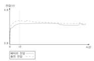
도 6a는 일 실시예에 따른 정상 충전 상황에서의 배터리 전압 및 시스템 전압을 도시한다.6A shows battery voltage and system voltage in a normal charging situation according to one embodiment.
상술한 바와 같이, 정상 충전 상황의 경우, 배터리(110)는 시각 t1에서 약 80%까지 충전될 수 있다. 또한, 정상 충전 상황에서, 시스템 전압과 배터리 전압의 차이는 충전 회로(130) 출력 전압의 약 10% 범위 내에서 유지될 수 있다. 또한, 예를 들어, 충전 개시 시각으로부터 시각 t1까지의 정전류 충전 구간의 길이는 대략 57분일 수 있다. 그러나, 후술하는 이유로서, 비정상 충전 상황이 유발될 수 있다.As described above, in the case of a normal charging situation, the
도 6b는 일 예시에 따른 비정상 충전 상황을 도시한다.6B illustrates an abnormal charging situation according to an example.
설명의 편의를 위하여, 도 6b는 도 6a와 동일한 축적으로 도시된다. 예를 들어, 상술한 바와 같은 배터리(110) 외부의 임피던스(예: 제1 임피던스(171))의 증가로 인하여 비정상적 충전 상황이 유발될 수 있다. 도 6b를 참조하여, 배터리(110) 외부의 임피던스의 증가로 인하여, 배터리 전압과 충전 전압의 차이가 크게 증가할 수 있다. 예를 들어, 시각 t2에서 충전 상태는 정전류 충전 상태로부터 정전압 충전 상태로 전환될 수 있다. 또한, 예를 들어, 충전 전압과 배터리 전압 사이의 차이는 충전 회로(130) 출력 전압의 약 40%에 대응할 수 있다. 또한, 정전류 충전 구간의 길이는 약 57분일 수 있다. 따라서, 도 6b의 비정상 충전 상황에 있어서, 충전 전압이 크게 증가할 수 있다. 충전 전압의 증가로 인하여 전자 장치(100)의 비정상적 발열 및 고장이 발생될 수 있다. 아울러, 외부 임피던스로 인하여 충전 시간이 증가될 수 있다.For convenience of description, FIG. 6B is drawn to the same scale as FIG. 6A. For example, an abnormal charging situation may be caused by an increase in an external impedance (eg, the first impedance 171) of the
따라서, 일 실시예에서, 상술한 바와 같이, 배터리 전압과 충전 전압의 차이가 지정된 값 보다 큰 경우, 비정상 충전 상태가 감지될 수 있다. 이 경우, 프로세서(120)는, 상술한 다양한 실시예들에 따라서, 비정상 충전 상태에 대응하여 배터리(110) 충전을 제어할 수 있다. 또한, 프로세서(120)는, 상술한 다양한 실시예들에 따라서, 비정상 충전 상태에 대한 정보를 제공할 수 있다. 또한, 도 6c와 관련하여 후술하는 바와 같이, 배터리(110)의 내부 임피던스의 증가로 인한 비정상 충전 상황이 유발될 수 있다.Accordingly, in one embodiment, as described above, when the difference between the battery voltage and the charging voltage is greater than a specified value, an abnormal charging state may be detected. In this case, the
도 6c는 다른 예시에 따른 비정상 충전 상황을 도시한다.6C illustrates an abnormal charging situation according to another example.
설명의 편의를 위하여, 도 6c는 도 6a와 동일한 축적으로 도시된다. 예를 들어, 배터리 내부의 임피던스(예: 제2 임피던스(172))의 증가로 인하여 비정상 충전 상황이 유발될 수 있다. 도 6c를 참조하여, 배터리(110) 내부 임피던스의 증가로 인하여 배터리 전압이 매우 빠르게 증가된다. 도 6c에서, 충전 상태는 시각 t3에서 정전류 충전 상태로부터 정전압 충전 상태로 전환될 수 있다. 정전압 충전 상태로의 전환이 배터리 전압에 기반하여 수행되는 경우, 도 6c의 비정상 충전 상황에서의 정전류 충전 구간은 도 6a의 정상 충전 상황에 비하여 짧을 수 있다. 예를 들어, 도 6c의 경우, 정전류 충전 구간의 길이는 약 30분일 수 있다. 따라서, 배터리(110)의 충전 상태가 낮음에도 불구하고, 충전 상태가 정전압 충전으로 변경될 수 있다. 이는 배터리(110)의 충전 시간의 증가를 유발할 수 있다.For convenience of description, FIG. 6C is drawn to the same scale as FIG. 6A. For example, an abnormal charging situation may be caused due to an increase in impedance (eg, the second impedance 172) inside the battery. Referring to FIG. 6C , the battery voltage increases very quickly due to an increase in internal impedance of the
도 6c에 도시된 바와 같이, 비정상 충전 상황에서, 배터리 전압과 충전 전압이 급격히 증가된다. 따라서, 일 실시예에서, 상술한 바와 같이, 배터리 전압의 변화 및/또는 충전 전압의 변화에 기반하여 비정상 충전 상태가 감지될 수 있다. 또한, 도 6c에 도시된 바와 같이, 비정상 충전 상황에서, 정전압 충전 전환 시간이 정상 충전 상황의 전환 시간보다 짧다. 따라서, 일 실시예에서, 정전압 충전 전환 시간에 기반하여 비정상 충전 상태가 감지될 수 있다. 또한, 상술한 바와 같이, 정전압 충전 전환 시각(t3)에서의 배터리(110)의 충전량이 정상 충전 상황보다 낮다. 따라서, 일 실시예에서, 배터리 전압 및 배터리 충전량에 기반하여 비정상 충전 상태가 감지될 수도 있다. 비정상 충전 상태가 감지된 경우, 프로세서(120)는, 상술한 다양한 실시예들에 따라서, 비정상 충전 상태에 대응하여 배터리(110) 충전을 제어할 수 있다. 또한, 프로세서(120)는, 상술한 다양한 실시예들에 따라서, 비정상 충전 상태에 대한 정보를 제공할 수 있다.As shown in FIG. 6C , in an abnormal charging situation, the battery voltage and charging voltage increase rapidly. Accordingly, in one embodiment, an abnormal charging state may be detected based on a change in battery voltage and/or a change in charging voltage, as described above. Also, as shown in FIG. 6C , in the abnormal charging situation, the constant voltage charging switching time is shorter than that in the normal charging situation. Accordingly, in one embodiment, an abnormal charging state may be detected based on the constant voltage charging transition time. In addition, as described above, the charged amount of the
이하에서, 도 7a, 7b, 및 7c를 참조하여 각 충전 상황 에서의 배터리 및 충전 전압의 변화가 보다 구체적으로 설명된다. 도 7a, 7b, 및 7c는 동일한 시간축 상의 레퍼런스 포인트 t1 및 t2를 갖는다.Hereinafter, changes in the battery and charging voltage in each charging situation are described in more detail with reference to FIGS. 7A, 7B, and 7C. 7a, 7b, and 7c have reference points t1 and t2 on the same time axis.
도 7a는 일 예시에 따른 구간별 충전 상태를 도시한다.7A illustrates a charging state for each section according to an example.
도 7a에서 도 6a의 정전류 충전 구간이 시간축 상에서 2배 신장되어 도시된다. 도 7a에서, 정상 충전 상황에 있어서의 배터리 전압 및 충전 전압 변화율이 각 구간(제1 구간 및 제2 구간) 별로 도시된다.In FIG. 7A, the constant current charging section of FIG. 6A is shown expanded twice on the time axis. In FIG. 7A , the battery voltage and charging voltage change rate in a normal charging situation are shown for each section (first section and second section).
도 7b는 다른 예시에 따른 구간별 충전 상태를 도시한다.7B illustrates a charging state for each section according to another example.
도 7b에서, 배터리(110) 외부의 임피던스가 증가로 인한 비정상 충전 상황이 가정된다. 도 7b에 도시된 바와 같이, 배터리 전압 및 충전 전압의 각 구간(제1 구간 및 제2 구간) 별 변화율은 정상 충전 상황과 유사하다. 그러나, 배터리 전압과 충전 전압 사이의 차이는 정상 충전 상황에 비하여 더 크다. 따라서, 상술한 바와 같이, 배터리 전압과 충전 전압 사이의 차이게 기반하여 비정상 충전 상황이 결정될 수 있다. 또한, 프로세서(120)는 배터리 전압과 충전 전압 사이의 차이에 기반하여 비정상 충전 상황의 원인을 결정할 수 있다.In FIG. 7B , an abnormal charging situation due to an increase in impedance outside the
도 7c는 또 다른 예시에 따른 구간별 충전 상태를 도시한다.7C illustrates a charging state for each section according to another example.
도 7c에서, 배터리(110) 내부의 임피던스의 증가로 인한 비정상 충전 상황이 가정된다. 도 7c에 도시된 바와 같이, 제1 구간에서의 배터리 전압 및 충전 전압의 변화율이 정상 충전 상황에 비하여 더 높다. 또한, 제2 구간에서의 배터리 전압 및 충전 전압의 변화율이 정상 충전 상황에 비하여 더 낮다. 따라서, 상술한 바와 같이, 지정된 시간 간격으로 배터리 전압과 충전 전압의 변화를 감지함으로써 비정상 충전 상황이 결정될 수 있다. 또한, 프로세서(120)는 배터리 전압 및/또는 충전 전압의 변화에 기반하여 비정상 충전 상황의 원인을 결정할 수 있다.In FIG. 7C, an abnormal charging situation due to an increase in impedance inside the
도 1 내지 7c와 관련하여 상술한 바와 같이, 다양한 기준에 기반하여 배터리(110)의 충전 상태 및 정전압 충전이 제어될 수 있다. 그러나, 예를 들어, 상술한 기준들은 배터리(110)와 전자 장치(100)의 열화와 같은 다양한 원인들에 의하여 변경될 수 있다. 따라서, 일 실시예에서, 이러한 기준들은 배터리(110) 및 전자 장치(100)의 열화에 대응하도록 트레이닝될 수도 있다.As described above with reference to FIGS. 1 to 7C , the state of charge and constant voltage charging of the
도 8은 다양한 실시예들에 따른 배터리 상태 결정 방법의 흐름도이다.8 is a flowchart of a method for determining a battery state according to various embodiments.
동작 801에서, 전자 장치(100)(예: 프로세서(120))는 배터리(110)를 정전류 상태로 충전할 수 있다. 예를 들어, 전자 장치(100)는 배터리 전압에 기반하여 정전류 충전을 수행할 수 있다. 예를 들어, 배터리(110)의 전압이 지정된 값 이하인 경우, 전자 장치(100)는 배터리(110)를 정전류 상태로 충전할 수 있다.In
동작 803에서, 전자 장치(100)(예: 프로세서(120))는 배터리 전압 및 충전 회로(130) 출력 전압을 확인할 수 있다. 일 실시예에서, 전자 장치(100)는 감지 회로(140)를 이용하여 배터리 전압 및 충전 회로(130) 출력 전압을 확인할 수 있다. 또한, 일 실시예에서, 전자 장치(100)는 제1 감지 회로(141) 및 제2 감지 회로(142)를 이용하여 배터리 전압 및 충전 회로(130) 출력 전압을 확인할 수 있다.In
일 실시예에서, 정전류 충전이 수행되는 동안, 전자 장치(100)(예: 프로세서(120))는 동작 803에서 확인된 배터리 전압 및/또는 충전 회로 출력 전압에 기반한 트레이닝을 수행할 수 있다. 예를 들어, 전자 장치(100)는 트레이닝 값을 저장할 수 있다. 예를 들어, 트레이닝 값은, 배터리 전압과 충전 회로(130)의 출력 전압의 차, 정전류 충전 구간의 길이, 배터리 전압 변화율, 배터리(110)의 임피던스 및/또는 충전 회로의 출력 전압 변화율을 포함할 수 있다. 예를 들어, 배터리 전압과 충전 회로의 출력 전압의 차는 지정된 배터리의 충전량과 연관되어 저장될 수 있다. 예를 들어, 정전류 충전 구간의 길이는 정전류 충전이 시작되었을 때의 배터리의 충전량 및 정전류 충전이 종료되었을 때의 배터리의 충전량과 함께 저장될 수 있다. 예를 들어, 정전류 충전 구간의 길이는 제1 값의 배터리 충전량으로부터 제2 값의 배터리 충전량에 도달하는데 소요된 시간 또는 배터리 충전량이 제3 값인 시각으로부터 정전류 충전이 종료된 시각까지의 시간일 수도 있다. 예를 들어, 배터리 전압 변화율 및/또는 충전 회로의 출력 전압 변화율은 지정된 시간 간격으로 각각의 전압값을 누적함으로써 저장될 수도 있다. 예를 들어, 배터리 전압 변화율 및/또는 충전 회로의 출력 전압 변화율은, 이전에 감지된 값과 현재 감지된 값의 차이 값으로 저장될 수도 있다.In an embodiment, while constant current charging is being performed, the electronic device 100 (eg, the processor 120) may perform training based on the battery voltage and/or the charging circuit output voltage checked in
일 실시예에서, 전자 장치(100)(예: 프로세서(120))는 복수의 시간 구간 각각에 대하여 배터리 전압 변화율 및/또는 충전 회로의 출력 전압 변화율을 저장할 수도 있다. 예를 들어, 복수의 시간 구간 각각의 길이는 배터리 전압 변화량 및/또는 충전 회로의 출력 전압 변화량에 따라서 트레이닝될 수도 있다. 또한, 예를 들어, 하나의 시간 구간 내에서의 배터리 전압 변화율 및/또는 충전 회로의 출력 전압 변화율이 임계값 이상인 경우, 시간 구간이 다음 시간 구간으로 변경될 수도 있다.In one embodiment, the electronic device 100 (eg, the processor 120) may store the battery voltage change rate and/or the output voltage change rate of the charging circuit for each of a plurality of time intervals. For example, the length of each of the plurality of time intervals may be trained according to the battery voltage change amount and/or the output voltage change amount of the charging circuit. Also, for example, when the battery voltage change rate and/or the output voltage change rate of the charging circuit within one time interval is greater than or equal to a threshold value, the time interval may be changed to the next time interval.
일 실시예에서, 전자 장치(100)(예: 프로세서(120))는 상술된 트레이닝 값을 적어도 일 회 이상 저장할 수 있다. 예를 들어, 한번의 정전류 충전이 완료된 경우, 일 회의 트레이닝이 완료될 수 있다. 일 실시예에서, 트레이닝 값이 지정된 횟수 이상 트레이닝된 경우, 전자 장치(100)(예: 프로세서(120))는 저장된 트레이닝 값들에 기반하여 배터리 충전을 제어하기 위한 파라미터들이 업데이트할 수 있다. 일 실시예에서, 트레이닝 값들의 평균 값에 기반하여 파라미터들이 업데이트될 수 있다. 또한, 일 실시예에서, 트레이닝 값들 중 비정상 충전 상태로 판단된 값들은 저장되지 않거나 평균 값의 계산에 이용되지 않을 수도 있다. 또한, 예를 들어, 트레이닝 값들 각각에 대하여 상이한 가중치가 설정될 수도 있다. 예를 들어, 충전을 제어하기 위한 파라미터들은, 배터리 및/또는 충전 회로 출력 전압을 측정하기 위한 시간 구간의 길이, 정상 충전 상황을 결정하기 위한 배터리 전압과 충전 회로 출력 전압의 차이, 정상 충전 상황을 결정하기 위한 배터리 전압 변화 및/또는 충전 회로 출력 전압 변화, 배터리 충전 양에 따른 배터리 전압과 충전 회로 출력 전압의 차이, 및/또는 정전류 충전 시간을 포함할 수 있다. 따라서, 트레이닝 값들을 이용함으로써, 전자 장치 및/또는 배터리의 성능 열화 및 특성 변화에 대응하도록 파라미터들이 업데이트될 수 있다.In one embodiment, the electronic device 100 (eg, the processor 120) may store the above-described training value at least once. For example, when constant current charging is completed once, training may be completed once. In an embodiment, when the training values are trained more than a specified number of times, the electronic device 100 (eg, the processor 120) may update parameters for controlling battery charging based on the stored training values. In one embodiment, parameters may be updated based on an average value of training values. Also, in an embodiment, values determined to be in an abnormal state of charge among training values may not be stored or used in calculating an average value. Also, for example, different weights may be set for each of the training values. For example, the parameters for controlling charging include the length of a time interval for measuring the battery and/or charging circuit output voltage, the difference between the battery voltage and the charging circuit output voltage for determining the normal charging state, and the normal charging state. The battery voltage change and/or the charging circuit output voltage change for determining, the difference between the battery voltage and the charging circuit output voltage according to the battery charge amount, and/or the constant current charging time may be included. Accordingly, by using the training values, parameters may be updated to respond to performance degradation and characteristic changes of the electronic device and/or battery.
동작 805에서, 전자 장치(100)(예: 프로세서(120))는 배터리 전압 및 충전 회로 출력 전압에 기반하여 배터리 상태를 결정할 수 있다. 예를 들어, 전자 장치(100)는 배터리 상태를 비정상 충전 상태 또는 정상 충전 상태로 결정할 수 있다. 배터리 상태 결정에 대한 설명은 도 1 내지 7c와 관련하여 상술한 설명에 의하여 참조될 수 있다.In
또한, 일 실시예에서, 전자 장치(100)(예: 프로세서(120))는 배터리(110)를 정전압 상태로 충전할 수 있다. 예를 들어, 상술한 바와 같이, 전자 장치(100)는 배터리 전압에 기반하여 정전압 상태 충전을 수행할 수도 있다. 또한, 상술한 다양한 실시예들과 같이, 비정상 충전 상황에서, 전자 장치는 정상 충전 상황과는 상이한 기준으로 배터리를 정전압 상태로 충전할 수도 있다.Also, in one embodiment, the electronic device 100 (eg, the processor 120) may charge the
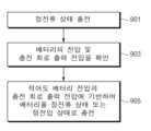
도 9는 다양한 실시예들에 따른 충전 제어 방법의 흐름도이다.9 is a flowchart of a charging control method according to various embodiments.
도 9의 동작 901 및 903에 대한 설명은 상술한 도 8의 동작 801 및 803에 대한 설명에 의하여 참조될 수 있다. 설명의 편의를 위하여, 중복된 설명은 생략된다.Descriptions of
동작 905에서, 전자 장치(100)(예: 프로세서(120))는 적어도 배터리 전압과 충전 회로 출력 전압에 기반하여 배터리(110)를 정전류 상태 또는 정전압 상태로 충전할 수 있다. 일 실시예에서, 배터리 전압과 출력 전압의 차이가 지정된 값 이하인 경우, 전자 장치(100)는 제1 기준에 따라서 배터리(110)를 정전류 상태 또는 정전압 상태로 충전할 수 있다. 예를 들어, 배터리 전압과 출력 전압의 차이가 지정된 값을 초과하는 경우, 전자 장치(100)는 제1 기준과는 상이한 제2 기준에 따라서 배터리(110)를 정전류 상태 또는 정전압 상태로 충전할 수 있다. 예를 들어, 제1 기준은 배터리 전압 값을 포함할 수 있다. 예를 들어, 제2 기준은 제1 기준과 상이한 배터리 전압 값을 포함할 수 있다. 일 실시예에서, 지정된 시간 간격으로 확인된 배터리 전압의 변화 및/또는 출력 전압의 변화가 지정된 제1 값 이하이고 지정된 제2 값 이상인 경우, 전자 장치(100)는 충전 회로(130)를 이용하여 제1 기준에 따라서 배터리를 정전류 상태 또는 정전압 상태로 충전할 수 있다. 예를 들어, 지정된 시간 간격으로 확인된 배터리 전압의 변화 및/또는 출력 전압의 변화가 지정된 제1 값을 초과하거나 지정된 제2 값 미만인 경우, 전자 장치(100)는 제2 기준에 따라서 배터리(110)를 정전압 상태 또는 정전류 상태로 충전할 수 있다. 예를 들어, 제1 값은 제2 값 이상일 수 있다. 예를 들어, 상술한 제1 값과 제2 값 중 적어도 하나는 이전에 확인된 배터리 전압의 변화 또는 출력 전압의 변화 중 적어도 하나에 기반하여 갱신된 값일 수 있다.In
도 9와 관련하여 상술한 바와 같이, 비정상 충전 상황에서 배터리(110)는 정상 충전 상황과 상이한 기준에 기반하여 충전될 수 있다. 또한, 비정상 충전 상황이 감지된 경우, 전자 장치(100)(예: 프로세서(120))는 배터리 상태에 대한 정보를 제공할 수 있다.As described above with respect to FIG. 9 , in an abnormal charging situation,
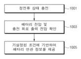
도 10은 다양한 실시예들에 따른 배터리 상태 제공 방법의 흐름도이다.10 is a flowchart of a method for providing a battery status according to various embodiments.
도 10의 동작 1001 및 1003에 대한 설명은 상술한 도 8의 동작 801 및 803에 대한 설명에 의하여 참조될 수 있다. 설명의 편의를 위하여, 중복된 설명은 생략된다.Descriptions of
동작 1005에서, 전자 장치(100)(예: 프로세서(120))는 지정된 조건에 기반하여 배터리 연관 정보를 제공할 수 있다. 예를 들어, 전자 장치(100)는, 배터리(110)의 충전 상태가 비정상 상태인 경우, 배터리 연관 정보를 제공할 수 있다. 예를 들어, 전자 장치(100)는 배터리의 충전 상태가 비정상 충전 상태인 경우, 배터리(110)에 대한 정보를 제공할 수도 있다. 예를 들어, 전자 장치(100)는 상술한 다양한 기준에 기반하여 비정상 충전 상태를 감지할 수 있다. 이 경우, 전자 장치(100)는 배터리(110)의 비정상 충전 상태를 나타내는 정보를 제공할 수 있다. 예를 들어, 전자 장치(100)는 비정상 충전 상태를 나타내는 시각적, 청각적, 및/또는 촉각적 정보를 제공할 수 있다.In
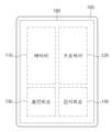
도 11은 다양한 실시예들에 따른 알림 제공 화면을 도시한다.11 illustrates a notification providing screen according to various embodiments.
상술한 바와 같이, 전자 장치(100)(예: 프로세서(120))는 지정된 조건에 기반하여 배터리(110)의 충전에 연관된 정보를 제공할 수 있다. 일 실시예에서, 전자 장치(100)는, 비정상 충전 상태가 감지된 경우에, 배터리 충전에 연관된 정보를 제공하도록 구성될 수 있다. 전자 장치(100)는, 예를 들어, 시각적, 청각적, 및/또는 촉각적 알림(notification)을 제공할 수 있다. 예를 들어, 알림은 비정상 충전 상태를 나타내는 이미지, 아이콘, 문자, 경고음, 및/또는 음성을 포함할 수 있다. 또한, 예를 들어, 알림은 비정상 충전 상태의 원인에 대한 정보를 더 포함할 수 있다. 일 실시예에서, 배터리 내부 임피던스의 변화로 인한 알림의 제1 메시지와 배터리 외부 임피던스의 변화로 인한 알림의 제2 메시지는 서로 상이하게 설정될 수 있다. 또한, 일 실시예에서, 알림은 비정상 충전 상황에 대응하는 권장 행동에 대한 정보를 포함할 수 있다.As described above, the electronic device 100 (eg, the processor 120) may provide information related to charging of the
도 11을 참조하여, 전자 장치(100)의 디스플레이(180) 상에 알림(1100)이 제공된다. 본 실시예에 있어서, 알림(1110)은 시각적 형태로서 도시되나, 알림(1100)은 청각적 및/또는 촉각적 알림이 함께 제공될 수 있다. 일 실시예에서, 전자 장치(100)(예: 프로세서(120))는 배터리 외부 임피던스의 변화로 인한 비정상 충전 상태를 감지하고, 비정상 충전 상태에 대응하여 알림(1100)을 제공할 수 있다.Referring to FIG. 11 , a
일 실시예에서, 알림(1100)은 지정된 배경 이미지 및 배경 이미지 상의 정보를 포함할 수 있다. 예를 들어, 알림(1100)은 팝업(pop up) 메시지로서 제공될 수 있다. 도 11의 예시에서, 알림(1100)은 아이콘(1105), 제1 디스플레이 영역(1110), 및 제2 디스플레이 영역(1115)을 포함할 수 있다.In one embodiment,
일 실시예에서, 아이콘(1105)은 알림을 나타내는 아이콘(예: 느낌표 등), 알림의 원인이 되는 구성에 대응하는 아이콘(예: 배터리(110) 형태 아이콘, 전자 장치(100) 형태 아이콘, 커넥터 모양 아이콘), 또는 요구되는 사용자 행동에 연관된 아이콘(예: 배터리 교환 또는 커넥터 재연결)에 대응할 수 있다.In one embodiment, the
일 실시예에서, 제1 디스플레이 영역(1110)에 비정상 충전 상태에 연관된 정보가 표시될 수 있다. 예를 들어, 비정상 충전 상태에 연관된 정보는 배터리(110) 또는 전자 장치(100)의 비정상 상태를 지시하는 정보, 또는 비정상 충전 상태의 원인(예: 배터리(110)의 외부 임피던스(예: 제1 임피던스(171)) 또는 배터리(110)의 내부 임피던스(예: 제2 임피던스(172))을 직간접적으로 지시하는 정보를 포함할 수 있다.In one embodiment, information related to the abnormal charging state may be displayed on the
일 실시예에서, 제2 디스플레이 영역(1115)에 비정상 충전 상태에 대응하는 행동(이하, 대응 행동으로 참조됨)에 대한 정보가 표시될 수 있다. 예를 들어, 대응 행동에 대한 정보는 커넥터의 전자 장치(100)로부터의 제거, 커넥터의 전자 장치(100)로의 재연결, 배터리(110)의 교체, 또는 전자 장치(100)의 파워오프(power-off)를 지시하는 정보에 대응할 수 있다. 일 실시예에서, 대응 행동에 대한 정보는 감지된 비정상 충전 상태에 대응한 전자 장치(100)의 동작을 지시하는 정보(예: 전자 장치(100)의 파워오프에 대한 정보)를 포함할 수도 있다.In one embodiment, information on a behavior corresponding to an abnormal charging state (hereinafter referred to as a corresponding behavior) may be displayed on the
일 실시예에서, 전자 장치(100)(예: 프로세서(120))는 배터리(110)의 비정상적 외부 임피던스(예: 제1 임피던스(171))로 인한 비정상 충전 상태를 감지하고 대응하는 알림(예: 알림(1100))을 디스플레이(180) 상에 표시할 수 있다. 예를 들어, 전자 장치(100)는 배터리(110) 형태 아이콘, 전자 장치(100) 형태 아이콘, 커넥터 형태 아이콘, 또는 커넥터 재연결에 대응하는 아이콘에 대응하는 아이콘을 아이콘(1105)으로서 표시할 수 있다. 예를 들어, 전자 장치(100)는 제1 디스플레이 영역(1110) 상에 충전에 이상이 있음을 나타내는 정보(예: “배터리 연결이 불완전합니다”)를 표시할 수 있다. 예를 들어, 전자 장치(100)는 제2 디스플레이 영역(1115) 상에 사용자를 위한 대응 행동에 대한 정보(예: “휴대폰 분해 후 배터리 재체결이 필요합니다”)를 표시할 수 있다.In one embodiment, the electronic device 100 (eg, the processor 120) detects an abnormal charging state due to an abnormal external impedance (eg, the first impedance 171) of the
일 실시예에서, 전자 장치(100)(예: 프로세서(120))는 배터리(110)의 비정상적 내부 임피던스(예: 제2 임피던스(172))로 인한 비정상 충전 상태를 감지하고 대응하는 알림(예: 알림(1100))을 디스플레이(180) 상에 표시할 수 있다. 예를 들어, 전자 장치(100)는 배터리(110) 형태 아이콘, 전자 장치(100) 형태 아이콘, 또는 배터리(110) 교체에 대응하는 아이콘을 아이콘(1105)으로서 표시할 수 있다. 예를 들어, 전자 장치(100)는 제1 디스플레이 영역(1110) 상에 충전에 이상이 있음을 나타내는 정보(예: “배터리 상태에 이상이 감지되었습니다”)를 표시할 수 있다. 예를 들어, 전자 장치(100)는 제2 디스플레이 영역(1115) 상에 사용자를 위한 대응 행동에 대한 정보(예: “배터리를 교체하여 주세요”)를 표시할 수 있다.In one embodiment, the electronic device 100 (eg, the processor 120) detects an abnormal charging state due to an abnormal internal impedance (eg, the second impedance 172) of the
도 11의 알림(1100)은 예시적인 것으로서, 알림(1100)은 도 11의 형태 및 도 11과 연관하여 상술된 설명의 실시예에 제한되는 것은 아니다. 일 실시예에서, 알림(1100)은 아이콘(1105), 제1 디스플레이 영역(1110), 또는 제2 디스플레이 영역(1115) 중 적어도 하나를 포함할 수 있다. 일 실시예에서, 알림(1100)에 포함된 시각적 요소(예: 아이콘(1105), 제1 디스플레이 영역(1110), 또는 제2 디스플레이 영역(1115))들은 도 11과 상이한 위치에 표시될 수도 있다.
상술된 바와 같이, 본 문서에 개시되는 전자 장치(예: 전자 장치(100))는, 배터리(예: 배터리(110)), 상기 배터리의 전압을 감지하기 위한 제1 감지 회로(예: 제1 감지회로(141)), 상기 배터리의 전압에 기반하여 상기 배터리를 정전류 상태 또는 정전압 상태로 충전하기 위한 충전 회로(예: 충전 회로(130)), 상기 충전 회로의 출력 전압을 감지하기 위한 제2 감지 회로 (예: 제2 감지회로(142)), 및 프로세서(예: 프로세서(120))를 포함하고, 상기 프로세서는, 상기 배터리가 상기 정전류 상태로 충전되는 동안, 상기 제1 감지 회로를 이용하여 상기 배터리의 전압 및 상기 제2 감지 회로를 이용하여 상기 출력 전압을 확인하고, 및 적어도 상기 배터리의 전압 및 상기 출력 전압에 기반하여 상기 배터리의 상태를 결정하도록 설정될 수 있다.As described above, an electronic device (eg, the electronic device 100) disclosed in this document includes a battery (eg, the battery 110), and a first sensing circuit (eg, the first sensing circuit) for sensing a voltage of the battery. A sensing circuit 141), a charging circuit (for example, a charging circuit 130) for charging the battery in a constant current state or a constant voltage state based on the voltage of the battery, and a second circuit for sensing an output voltage of the charging circuit. A sensing circuit (eg, the second sensing circuit 142) and a processor (eg, the processor 120), wherein the processor uses the first sensing circuit while the battery is being charged in the constant current state. to check the output voltage using the voltage of the battery and the second sensing circuit, and to determine the state of the battery based on at least the voltage of the battery and the output voltage.
일 실시예에 따른 프로세서는, 상기 배터리의 전압과 상기 출력 전압의 차이가 지정된 제1 값 미만인 경우에 상기 배터리의 상태를 정상 충전 상태로 결정하고, 및 상기 배터리의 전압과 상기 출력 전압의 차이가 상기 지정된 제1 값 이상인 경우에 상기 배터리의 상태를 비정상 충전 상태로 결정하도록 설정될 수 있다.The processor according to an embodiment determines the state of the battery as a normal charge state when the difference between the voltage of the battery and the output voltage is less than a specified first value, and the difference between the voltage of the battery and the output voltage is It may be set to determine the state of the battery as an abnormal charging state when the value is equal to or greater than the specified first value.
일 실시예에서, 상기 배터리의 상태가 정상 충전 상태로 결정된 경우, 상기 프로세서는, 상기 배터리의 전압이 지정된 값 이상인 경우에 상기 배터리를 상기 정전압 상태로 충전하고 상기 배터리의 전압이 상기 지정된 값 미만인 경우에 상기 배터리를 상기 정전류 상태로 충전하도록 설정될 수 있다.In one embodiment, when the state of the battery is determined to be a normal charge state, the processor charges the battery to the constant voltage state when the voltage of the battery is greater than or equal to a specified value, and when the voltage of the battery is less than the specified value may be set to charge the battery in the constant current state.
일 실시예에 따른 상기 프로세서는, 상기 배터리의 전압 및 상기 출력 전압의 확인을 지정된 시간 간격으로 수행하고, 및 상기 지정된 시간 간격으로 확인된 상기 배터리 전압의 변화 또는 상기 출력 전압의 변화 중 적어도 하나에 기반하여 상기 배터리의 상태를 결정하도록 설정될 수 있다.The processor according to an embodiment performs the check of the voltage of the battery and the output voltage at a specified time interval, and determines at least one of a change in the battery voltage or a change in the output voltage determined at the specified time interval. Based on this, it may be set to determine the state of the battery.
일 실시예에 따른 상기 프로세서는, 상기 배터리 전압의 변화 또는 상기 출력 전압의 변화 중 적어도 하나를 지정된 제2 값과 비교함으로써 상기 배터리의 상태를 결정하도록 설정될 수 있다.The processor according to an embodiment may be configured to determine the state of the battery by comparing at least one of a change in the battery voltage or a change in the output voltage with a designated second value.
일 실시예에서, 상기 지정된 제2 값은 이전에 확인된 상기 배터리 전압의 변화 또는 상기 출력 전압의 변화 중 적어도 하나에 기반하여 갱신될 수 있다.In one embodiment, the designated second value may be updated based on at least one of a previously identified change in the battery voltage or change in the output voltage.
일 실시예에 따른 상기 프로세서는, 상기 배터리의 상태가 비정상 충전 상태로 결정된 경우, 상기 충전 회로를 이용하여, 상기 배터리의 상태가 정상 충전 상태인 경우와는 상이한 기준에 기반하여 상기 배터리를 상기 정전류 상태 또는 상기 정전압 상태로 충전하도록 설정될 수 있다.The processor according to an embodiment may, when the battery state is determined to be in an abnormal charging state, use the charging circuit to set the battery to the constant current based on a different criterion than when the battery state is in a normal charging state. state or the constant voltage state may be set to charge.
일 실시예에 따른 상기 충전 회로는 상기 배터리의 충전량을 감지하도록 설정되고, 상기 프로세서는, 상기 배터리의 상태가 비정상 충전 상태로 결정된 경우, 상기 충전 회로를 이용하여, 상기 배터리의 충전량에 기반하여 상기 배터리를 상기 정전류 상태 또는 상기 정전압 상태로 충전하도록 설정될 수 있다.The charging circuit according to an embodiment is configured to sense the amount of charge of the battery, and the processor, when the state of the battery is determined to be an abnormal state of charge, uses the charging circuit to determine the amount of charge of the battery based on the amount of charge of the battery. It may be set to charge the battery in the constant current state or the constant voltage state.
일 실시예에 따른 상기 프로세서는, 상기 배터리의 상태가 정상 충전 상태로 결정된 경우, 상기 배터리의 전압을 지정된 제1 값과 비교함으로써 상기 배터리를 상기 정전류 상태 또는 상기 정전압 상태로 충전하고, 및 상기 배터리의 상태가 정상 충전 상태로 결정된 경우, 상기 배터리의 전압을 상기 지정된 제1 값과 상이한 지정된 제2 값과 비교함으로써 상기 배터리를 상기 정전류 상태 또는 상기 정전압 상태로 충전하도록 설정될 수 있다.When the state of the battery is determined to be a normal charge state, the processor according to an embodiment compares a voltage of the battery with a designated first value to charge the battery in the constant current state or the constant voltage state, and the battery When the state of is determined to be a normal charging state, it may be set to charge the battery in the constant current state or the constant voltage state by comparing the voltage of the battery with a designated second value different from the designated first value.
일 실시예에 따른 상기 프로세서는, 상기 배터리의 상태가 비정상 충전 상태로 결정된 경우, 상기 충전 회로를 이용하여, 상기 배터리의 전압으로부터 독립적으로 상기 배터리를 상기 정전압 상태로 충전하도록 설정된, 전자 장치.The processor according to an embodiment is configured to charge the battery to the constant voltage state independently from the voltage of the battery using the charging circuit when the state of the battery is determined to be an abnormal charging state.
일 실시예에 따른 상기 전자 장치는 표시 장치를 더 포함하고, 상기 프로세서는, 상기 배터리의 상태가 비정상 충전 상태로 결정된 경우, 상기 표시 장치를 이용하여 상기 배터리의 충전 상태에 연관된 정보를 제공하도록 설정될 수 있다.The electronic device according to an embodiment further includes a display device, and the processor is set to provide information related to the state of charge of the battery using the display device when the state of the battery is determined to be an abnormal state of charge. It can be.
일 실시예에서, 상기 배터리의 충전 상태에 연관된 정보는 비정상 충전 상태 또는 상기 비정상 충전 상태에 대응하는 지시(instruction) 중 적어도 하나를 나타내는 정보를 포함할 수 있다.In one embodiment, the information related to the state of charge of the battery may include information indicating at least one of an abnormal state of charge or an instruction corresponding to the state of abnormal state of charge.
일 실시예에 따른 상기 전자 장치는 음향 출력 장치를 더 포함하고,The electronic device according to an embodiment further includes a sound output device,
상기 프로세서는, 상기 배터리의 상태가 비정상 충전 상태로 결정된 경우, 상기 음향 출력 장치를 이용하여 상기 배터리의 충전 상태에 연관된 정보를 제공하도록 설정될 수 있다.When the state of the battery is determined to be an abnormal state of charge, the processor may be configured to provide information related to the state of charge of the battery using the sound output device.
상술된 바와 같이, 본 문서에 개시되는 전자 장치(예: 전자 장치(100))는, 배터리(예: 배터리(110)), 상기 배터리의 전압을 감지하기 위한 제1 감지 회로(예: 제1 감지회로(141)), 상기 배터리의 전압에 기반하여 상기 배터리를 정전류 상태 또는 정전압 상태로 충전하기 위한 충전 회로(예: 충전회로(130)), 상기 충전 회로의 출력 전압을 감지하기 위한 제2 감지 회로(예: 제2 감지 회로(142)), 및 프로세서(예: 프로세서(120))를 포함하고, 상기 프로세서는, 상기 배터리가 상기 정전류 상태로 충전되는 동안, 상기 배터리의 전압 및 상기 출력 전압을 상기 제1 감지 회로 및 상기 제2 감지 회로를 각각 이용하여 확인하고, 상기 출력 전압 및 상기 배터리 전압의 차가 지정된 값 이하인 경우, 상기 충전 회로를 이용하여 제1 기준에 따라서 상기 배터리를 상기 정전류 상태 또는 상기 정전압 상태로 충전하고, 및 상기 출력 전압 및 상기 배터리 전압의 차가 상기 지정된 값을 초과하는 경우, 상기 충전 회로를 이용하여 상기 제1 기준과 상이한 상기 제2 기준에 따라서 상기 배터리를 상기 정전류 상태 또는 상기 정전압 상태로 충전하도록 설정되고, 상기 제1 기준은 제1 배터리 전압 값을 포함할 수 있다.As described above, an electronic device (eg, the electronic device 100) disclosed in this document includes a battery (eg, the battery 110), and a first sensing circuit (eg, the first sensing circuit) for sensing a voltage of the battery. A sensing circuit 141), a charging circuit (for example, a charging circuit 130) for charging the battery in a constant current state or a constant voltage state based on the voltage of the battery, and a second circuit for sensing an output voltage of the charging circuit. A sensing circuit (eg, the second sensing circuit 142) and a processor (eg, the processor 120), wherein the processor determines the voltage of the battery and the output while the battery is being charged in the constant current state. The voltage is checked using the first sensing circuit and the second sensing circuit, respectively, and when the difference between the output voltage and the battery voltage is less than or equal to a specified value, the battery is charged with the constant current according to a first criterion using the charging circuit. state or the constant voltage state, and when the difference between the output voltage and the battery voltage exceeds the designated value, the battery is charged according to the second criterion different from the first criterion using the charging circuit at the constant current state or set to be charged in the constant voltage state, and the first reference may include a first battery voltage value.
일 실시예에서, 상기 제2 기준은 상기 제1 배터리 전압 값과 상이한 제2 배터리 전압 값 또는 상기 배터리의 충전량 중 적어도 하나를 포함할 수 있다.In an embodiment, the second criterion may include at least one of a second battery voltage value different from the first battery voltage value or a charge amount of the battery.
일 실시예에 따른 상기 프로세서는, 상기 배터리의 전압 및 상기 출력 전압의 확인을 지정된 시간 간격으로 수행하고, 상기 지정된 시간 간격으로 확인된 상기 배터리 전압의 변화 및 상기 출력 전압의 변화가 지정된 제1 값 이하이고 지정된 제2 값 이상인 경우, 상기 충전 회로를 이용하여 상기 제1 기준에 따라서 상기 배터리를 상기 정전류 상태 또는 상기 정전압 상태로 충전하고, 및 상기 지정된 시간 간격으로 확인된 상기 배터리 전압의 변화 또는 상기 출력 전압의 변화가 상기 지정된 제1 값을 초과하거나 상기 지정된 제2 값 미만인 경우, 상기 충전 회로를 이용하여 상기 제2 기준에 따라서 상기 배터리를 상기 정전류 상태 또는 상기 정전압 상태로 충전하도록 설정되고, 상기 제1 값은 상기 제2 값 보다 클 수 있다.The processor according to an embodiment performs the check of the voltage of the battery and the output voltage at a specified time interval, and the change of the battery voltage and the change of the output voltage checked at the specified time interval are specified first values. or less than the specified second value, the battery is charged in the constant current state or the constant voltage state according to the first criterion using the charging circuit, and the change in the battery voltage checked at the specified time interval or the set to charge the battery in the constant current state or the constant voltage state according to the second criterion using the charging circuit when the change in output voltage exceeds the specified first value or is less than the specified second value; The first value may be greater than the second value.
일 실시예에서, 상기 지정된 제1 값 또는 상기 지정된 제2 값 중 적어도 하나는 이전에 확인된 상기 배터리 전압의 변화 또는 상기 출력 전압의 변화 중 적어도 하나에 기반하여 갱신될 수 있다.In one embodiment, at least one of the designated first value and the designated second value may be updated based on at least one of a previously identified change in the battery voltage or change in the output voltage.
상술된 바와 같이, 본 문서에 개시되는 전자 장치(예: 전자 장치(100))는, 배터리(예: 배터리(110)), 상기 배터리의 전압을 감지하기 위한 제1 감지 회로(예: 제1 감지회로(141)), 상기 배터리의 전압에 기반하여 상기 배터리를 정전류 상태 또는 정전압 상태로 충전하기 위한 충전 회로(예: 충전회로(130)), 상기 충전 회로의 출력 전압을 감지하기 위한 제2 감지 회로(예: 제2 감지 회로(142)), 디스플레이(예: 디스플레이(180)), 및 프로세서(예: 프로세서(120))를 포함하고, 상기 프로세서는, 상기 배터리가 상기 정전류 상태로 충전되는 동안, 상기 배터리의 전압 및 상기 출력 전압을 상기 제1 감지 회로 및 상기 제2 감지 회로를 각각 이용하여 주기적으로 확인하고, 및 상기 배터리의 전압과 상기 출력 전압의 차이, 상기 주기적으로 확인된 상기 배터리의 전압의 변화, 또는 상기 주기적으로 확인된 상기 출력 전압의 변화 중 적어도 하나에 기반하여 상기 배터리의 충전 상태에 대한 정보를 상기 디스플레이를 통하여 제공하도록 설정될 수 있다.As described above, an electronic device (eg, the electronic device 100) disclosed in this document includes a battery (eg, the battery 110), and a first sensing circuit (eg, the first sensing circuit) for sensing a voltage of the battery. A sensing circuit 141), a charging circuit (for example, a charging circuit 130) for charging the battery in a constant current state or a constant voltage state based on the voltage of the battery, and a second circuit for sensing an output voltage of the charging circuit. A sensing circuit (eg, the second sensing circuit 142), a display (eg, the display 180), and a processor (eg, the processor 120), wherein the processor charges the battery in the constant current state. During this period, the voltage of the battery and the output voltage are periodically checked using the first sensing circuit and the second sensing circuit, respectively, and the difference between the voltage of the battery and the output voltage, the periodically checked Information on the state of charge of the battery may be provided through the display based on at least one of a change in the voltage of the battery and a change in the periodically checked output voltage.
일 실시예에 따른 상기 프로세서는, 상기 주기적으로 확인된 상기 배터리의 전압의 변화 또는 상기 주기적으로 확인된 상기 출력 전압의 변화 중 적어도 하나에 기반하여 상기 배터리의 충전 상태에 대한 정보를 상기 디스플레이를 통하여 제공하도록 설정될 수 있다.The processor according to an embodiment, based on at least one of the periodically checked voltage change of the battery and the periodically checked output voltage change, transmits information on the state of charge of the battery through the display. can be set to provide
일 실시예에서, 상기 배터리의 충전 상태에 대한 정보는 비정상 충전 상태 또는 상기 비정상 충전 상태에 대응하는 지시(instruction) 중 적어도 하나를 나타내는 정보를 포함할 수 있다.In one embodiment, the information on the state of charge of the battery may include information indicating at least one of an abnormal state of charge or an instruction corresponding to the state of abnormal state of charge.
이하에서, 도 12 및 도 13를 참조하여, 도 1 내지 도 11과 관련하여 상술한 다양한 실시예들을 수행하기 위한 전자 장치(100)의 구성이 설명된다.Hereinafter, with reference to FIGS. 12 and 13, the configuration of the
도 12는, 다양한 실시예들에 따른, 네트워크 환경(1200) 내의 전자 장치(1201)(예: 전자 장치(100))의 블럭도이다. 도 12를 참조하면, 네트워크 환경(1200)에서 전자 장치(1201)는 제 1 네트워크(1298)(예: 근거리 무선 통신)를 통하여 전자 장치(1202)와 통신하거나, 또는 제 2 네트워크(1299)(예: 원거리 무선 통신)를 통하여 전자 장치(1204) 또는 서버(1208)와 통신할 수 있다. 일 실시예에 따르면, 전자 장치(1201)는 서버(1208)를 통하여 전자 장치(1204)와 통신할 수 있다. 일실시예에 따르면, 전자 장치(1201)는 프로세서(1220)(예: 프로세서(120)), 메모리(1230), 입력 장치(1250), 음향 출력 장치(1255), 표시 장치(1260)(예: 디스플레이(180)), 오디오 모듈(1270), 센서 모듈(1276), 인터페이스(1277), 햅틱 모듈(1279), 카메라 모듈(1280), 전력 관리 모듈(1288)(예: 충전 회로(130) 및 감지회로 (140)), 배터리(1289)(예: 배터리 (110)), 통신 모듈(1290), 가입자 식별 모듈(1296), 및 안테나 모듈(1297)을 포함할 수 있다. 어떤 실시예에서는, 전자 장치(1201)에는, 이 구성요소들 중 적어도 하나(예: 표시 장치(1260) 또는 카메라 모듈(1280))가 생략되거나 다른 구성 요소가 추가될 수 있다. 어떤 실시예에서는, 예를 들면, 표시 장치(1260)(예: 디스플레이)에 임베디드된 센서 모듈(1276)(예: 지문 센서, 홍채 센서, 또는 조도 센서)의 경우와 같이, 일부의 구성요소들이 통합되어 구현될 수 있다.12 is a block diagram of an electronic device 1201 (eg, the electronic device 100) within the
프로세서(1220)는, 예를 들면, 소프트웨어(예: 프로그램(1240))를 구동하여 프로세서(1220)에 연결된 전자 장치(1201)의 적어도 하나의 다른 구성요소(예: 하드웨어 또는 소프트웨어 구성요소)을 제어할 수 있고, 다양한 데이터 처리 및 연산을 수행할 수 있다. 프로세서(1220)는 다른 구성요소(예: 센서 모듈(1276) 또는 통신 모듈(1290))로부터 수신된 명령 또는 데이터를 휘발성 메모리(1232)에 로드하여 처리하고, 결과 데이터를 비휘발성 메모리(1234)에 저장할 수 있다. 일 실시예에 따르면, 프로세서(1220)는 메인 프로세서(1221)(예: 중앙 처리 장치 또는 어플리케이션 프로세서), 및 이와는 독립적으로 운영되고, 추가적으로 또는 대체적으로, 메인 프로세서(1221)보다 저전력을 사용하거나, 또는 지정된 기능에 특화된 보조 프로세서(1223)(예: 그래픽 처리 장치, 이미지 시그널 프로세서, 센서 허브 프로세서, 또는 커뮤니케이션 프로세서)를 포함할 수 있다. 여기서, 보조 프로세서(1223)는 메인 프로세서(1221)와 별개로 또는 임베디드되어 운영될 수 있다.The processor 1220, for example, drives software (eg, the program 1240) to operate at least one other component (eg, hardware or software component) of the electronic device 1201 connected to the processor 1220. It can control and perform various data processing and calculations. The processor 1220 loads commands or data received from other components (eg, the sensor module 1276 or the communication module 1290) into the volatile memory 1232 for processing, and transfers the resulting data to the non-volatile memory 1234. can be stored in According to one embodiment, the processor 1220 is operated independently of the main processor 1221 (eg, a central processing unit or application processor), and additionally or alternatively, uses less power than the main processor 1221, Alternatively, an
이런 경우, 보조 프로세서(1223)는, 예를 들면, 메인 프로세서(1221)가 인액티브(예: 슬립) 상태에 있는 동안 메인 프로세서(1221)를 대신하여, 또는 메인 프로세서(1221)가 액티브(예: 어플리케이션 수행) 상태에 있는 동안 메인 프로세서(1221)와 함께, 전자 장치(1201)의 구성요소들 중 적어도 하나의 구성요소(예: 표시 장치(1260), 센서 모듈(1276), 또는 통신 모듈(1290))와 관련된 기능 또는 상태들의 적어도 일부를 제어할 수 있다. 일 실시예에 따르면, 보조 프로세서(1223)(예: 이미지 시그널 프로세서 또는 커뮤니케이션 프로세서)는 기능적으로 관련 있는 다른 구성 요소(예: 카메라 모듈(1280) 또는 통신 모듈(1290))의 일부 구성 요소로서 구현될 수 있다. 메모리(1230)는, 전자 장치(1201)의 적어도 하나의 구성요소(예: 프로세서(1220) 또는 센서모듈(1276))에 의해 사용되는 다양한 데이터, 예를 들어, 소프트웨어(예: 프로그램(1240)) 및, 이와 관련된 명령에 대한 입력 데이터 또는 출력 데이터를 저장할 수 있다. 메모리(1230)는, 휘발성 메모리(1232) 또는 비휘발성 메모리(1234)를 포함할 수 있다. In this case, the
프로그램(1240)은 메모리(1230)에 저장되는 소프트웨어로서, 예를 들면, 운영 체제(1242), 미들 웨어(1244) 또는 어플리케이션(1246)을 포함할 수 있다.The program 1240 is software stored in the memory 1230 and may include, for example, an operating system 1242 , middleware 1244 , or an application 1246 .
입력 장치(1250)는, 전자 장치(1201)의 구성요소(예: 프로세서(1220))에 사용될 명령 또는 데이터를 전자 장치(1201)의 외부(예: 사용자)로부터 수신하기 위한 장치로서, 예를 들면, 마이크, 마우스, 또는 키보드를 포함할 수 있다.The
음향 출력 장치(1255)는 음향 신호를 전자 장치(1201)의 외부로 출력하기 위한 장치로서, 예를 들면, 멀티미디어 재생 또는 녹음 재생과 같이 일반적인 용도로 사용되는 스피커와 전화 수신 전용으로 사용되는 리시버를 포함할 수 있다. 일 실시예에 따르면, 리시버는 스피커와 일체 또는 별도로 형성될 수 있다.The
표시 장치(1260)는 전자 장치(1201)의 사용자에게 정보를 시각적으로 제공하기 위한 장치로서, 예를 들면, 디스플레이, 홀로그램 장치, 또는 프로젝터 및 해당 장치를 제어하기 위한 제어 회로를 포함할 수 있다. 일 실시예에 따르면, 표시 장치(1260)는 터치 회로(touch circuitry) 또는 터치에 대한 압력의 세기를 측정할 수 있는 압력 센서를 포함할 수 있다.The display device 1260 is a device for visually providing information to the user of the electronic device 1201, and may include, for example, a display, a hologram device, or a projector and a control circuit for controlling the device. According to an embodiment, the display device 1260 may include a touch circuitry or a pressure sensor capable of measuring the intensity of a touch pressure.
오디오 모듈(1270)은 소리와 전기 신호를 쌍방향으로 변환시킬 수 있다. 일 실시예에 따르면, 오디오 모듈(1270)은, 입력 장치(1250)를 통해 소리를 획득하거나, 음향 출력 장치(1255), 또는 전자 장치(1201)와 유선 또는 무선으로 연결된 외부 전자 장치(예: 전자 장치(1202)(예: 스피커 또는 헤드폰))를 통해 소리를 출력할 수 있다.The
센서 모듈(1276)은 전자 장치(1201)의 내부의 작동 상태(예: 전력 또는 온도), 또는 외부의 환경 상태에 대응하는 전기 신호 또는 데이터 값을 생성할 수 있다. 센서 모듈(1276)은, 예를 들면, 제스처 센서, 자이로 센서, 기압 센서, 마그네틱 센서, 가속도 센서, 그립 센서, 근접 센서, 컬러 센서, IR(infrared) 센서, 생체 센서, 온도 센서, 습도 센서, 또는 조도 센서를 포함할 수 있다.The sensor module 1276 may generate an electrical signal or data value corresponding to an internal operating state (eg, power or temperature) of the electronic device 1201 or an external environmental state. The sensor module 1276 may include, for example, a gesture sensor, a gyro sensor, an air pressure sensor, a magnetic sensor, an acceleration sensor, a grip sensor, a proximity sensor, a color sensor, an IR (infrared) sensor, a bio sensor, a temperature sensor, a humidity sensor, Alternatively, an illuminance sensor may be included.
인터페이스(1277)는 외부 전자 장치(예: 전자 장치(1202))와 유선 또는 무선으로 연결할 수 있는 지정된 프로토콜을 지원할 수 있다. 일 실시예에 따르면, 인터페이스(1277)는 HDMI(high definition multimedia interface), USB(universal serial bus) 인터페이스, SD카드 인터페이스, 또는 오디오 인터페이스를 포함할 수 있다.The
연결 단자(1278)는 전자 장치(1201)와 외부 전자 장치(예: 전자 장치(1202))를 물리적으로 연결시킬 수 있는 커넥터, 예를 들면, HDMI 커넥터, USB 커넥터, SD 카드 커넥터, 또는 오디오 커넥터(예: 헤드폰 커넥터)를 포함할 수 있다.The
햅틱 모듈(1279)은 전기적 신호를 사용자가 촉각 또는 운동 감각을 통해서 인지할 수 있는 기계적인 자극(예: 진동 또는 움직임) 또는 전기적인 자극으로 변환할 수 있다. 햅틱 모듈(1279)은, 예를 들면, 모터, 압전 소자, 또는 전기 자극 장치를 포함할 수 있다.The haptic module 1279 may convert electrical signals into mechanical stimuli (eg, vibration or movement) or electrical stimuli that a user may perceive through tactile or kinesthetic senses. The haptic module 1279 may include, for example, a motor, a piezoelectric element, or an electrical stimulation device.
카메라 모듈(1280)은 정지 영상 및 동영상을 촬영할 수 있다. 일 실시예에 따르면, 카메라 모듈(1280)은 하나 이상의 렌즈, 이미지 센서, 이미지 시그널 프로세서, 또는 플래시를 포함할 수 있다.The camera module 1280 may capture still images and moving images. According to one embodiment, the camera module 1280 may include one or more lenses, image sensors, image signal processors, or flashes.
전력 관리 모듈(1288)은 전자 장치(1201)에 공급되는 전력을 관리하기 위한 모듈로서, 예를 들면, PMIC(power management integrated circuit)의 적어도 일부로서 구성될 수 있다.The
배터리(1289)는 전자 장치(1201)의 적어도 하나의 구성 요소에 전력을 공급하기 위한 장치로서, 예를 들면, 재충전 불가능한 1차 전지, 재충전 가능한 2차 전지 또는 연료 전지를 포함할 수 있다.The
통신 모듈(1290)은 전자 장치(1201)와 외부 전자 장치(예: 전자 장치(1202), 전자 장치(1204), 또는 서버(1208))간의 유선 또는 무선 통신 채널의 수립, 및 수립된 통신 채널을 통한 통신 수행을 지원할 수 있다. 통신 모듈(1290)은 프로세서(1220)(예: 어플리케이션 프로세서)와 독립적으로 운영되는, 유선 통신 또는 무선 통신을 지원하는 하나 이상의 커뮤니케이션 프로세서를 포함할 수 있다. 일 실시예에 따르면, 통신 모듈(1290)은 무선 통신 모듈(1292)(예: 셀룰러 통신 모듈, 근거리 무선 통신 모듈, 또는 GNSS(global navigation satellite system) 통신 모듈) 또는 유선 통신 모듈(1294)(예: LAN(local area network) 통신 모듈, 또는 전력선 통신 모듈)을 포함하고, 그 중 해당하는 통신 모듈을 이용하여 제 1 네트워크(1298)(예: 블루투스, WiFi direct 또는 IrDA(infrared data association) 같은 근거리 통신 네트워크) 또는 제 2 네트워크(1299)(예: 셀룰러 네트워크, 인터넷, 또는 컴퓨터 네트워크(예: LAN 또는 WAN)와 같은 원거리 통신 네트워크)를 통하여 외부 전자 장치와 통신할 수 있다. 상술한 여러 종류의 통신 모듈(1290)은 하나의 칩으로 구현되거나 또는 각각 별도의 칩으로 구현될 수 있다.The communication module 1290 establishes a wired or wireless communication channel between the electronic device 1201 and an external electronic device (eg, the
일 실시예에 따르면, 무선 통신 모듈(1292)은 가입자 식별 모듈(1296)에 저장된 사용자 정보를 이용하여 통신 네트워크 내에서 전자 장치(1201)를 구별 및 인증할 수 있다.According to an embodiment, the wireless communication module 1292 may distinguish and authenticate the electronic device 1201 within a communication network using user information stored in the
안테나 모듈(1297)은 신호 또는 전력을 외부로 송신하거나 외부로부터 수신하기 위한 하나 이상의 안테나들을 포함할 수 있다. 일시예에 따르면, 통신 모듈(1290)(예: 무선 통신 모듈(1292))은 통신 방식에 적합한 안테나를 통하여 신호를 외부 전자 장치로 송신하거나, 외부 전자 장치로부터 수신할 수 있다.The
상기 구성요소들 중 일부 구성요소들은 주변 기기들간 통신 방식(예: 버스, GPIO(general purpose input/output), SPI(serial peripheral interface), 또는 MIPI(mobile industry processor interface))를 통해 서로 연결되어 신호(예: 명령 또는 데이터)를 상호간에 교환할 수 있다.Some of the above components are connected to each other through a communication method between peripheral devices (e.g., a bus, GPIO (general purpose input/output), SPI (serial peripheral interface), or MIPI (mobile industry processor interface)) and signal (e.g. commands or data) can be exchanged with each other.
일 실시예에 따르면, 명령 또는 데이터는 제 2 네트워크(1299)에 연결된 서버(1208)를 통해서 전자 장치(1201)와 외부의 전자 장치(1204)간에 송신 또는 수신될 수 있다. 전자 장치(1202, 1204) 각각은 전자 장치(1201)와 동일한 또는 다른 종류의 장치일 수 있다. 일 실시예에 따르면, 전자 장치(1201)에서 실행되는 동작들의 전부 또는 일부는 다른 하나 또는 복수의 외부 전자 장치에서 실행될 수 있다. 일 실시예에 따르면, 전자 장치(1201)가 어떤 기능이나 서비스를 자동으로 또는 요청에 의하여 수행해야 할 경우에, 전자 장치(1201)는 기능 또는 서비스를 자체적으로 실행시키는 대신에 또는 추가적으로, 그와 연관된 적어도 일부 기능을 외부 전자 장치에게 요청할 수 있다. 상기 요청을 수신한 외부 전자 장치는 요청된 기능 또는 추가 기능을 실행하고, 그 결과를 전자 장치(1201)로 전달할 수 있다. 전자 장치(1201)는 수신된 결과를 그대로 또는 추가적으로 처리하여 요청된 기능이나 서비스를 제공할 수 있다. 이를 위하여, 예를 들면, 클라우드 컴퓨팅, 분산 컴퓨팅, 또는 클라이언트-서버 컴퓨팅 기술이 이용될 수 있다. According to an embodiment, commands or data may be transmitted or received between the electronic device 1201 and the external
도 12의 전자 장치(1201)는 도 1 내지 도 11과 관련하여 상술한 전자 장치(100)에 대응할 수 있다. 예를 들어, 배터리(1289)는 도 1 내지 도 11과 관련하여 상술한 배터리(110)에 대응할 수 있다. 또한, 표시 장치(1260)는 상술한 디스플레이(180)에 대응할 수 있다. 예를 들어, 프로세서(1223)는 상술한 프로세서(120)에 대응할 수 있다. 또한, 전력 관리 모듈(1288)은 충전 회로(130), 전력 조정기(150), 감지 회로(140), 및/또는 제1 감지 회로(141)를 포함할 수 있다. 예를 들어, 제2 감지 회로(142)는 전력 관리 모듈(1288)에 포함되거나 전력 관리 모듈(1288)과 상이한 구성으로서 구현될 수도 있다.The electronic device 1201 of FIG. 12 may correspond to the
도 13은, 다양한 실시예들에 따른, 전력 관리 모듈(1288) 및 배터리(1289)(예: 배터리(110))에 대한 블럭도(1300)이다. 도 13을 참조하면, 전력 관리 모듈(1288)은 충전 회로(1310)(예: 충전 회로(130)), 전력 조정기(1320)(예: 전력 조정기(150)), 또는 연료 게이지(1330)(예: 감지 회로(140), 제1 감지 회로(141), 및/또는 제2 감지 회로(142))를 포함할 수 있다. 충전 회로(1310)는 전자 장치(1201)(예: 전자 장치(100))에 대한 외부 전원(예: 전력 공급원(200))으로부터 공급되는 전력을 이용하여 배터리(1289)를 충전할 수 있다. 일 실시예에 따르면, 충전 회로(1310)는 외부 전원의 종류(예: 전원 어댑터, USB 또는 무선충전), 상기 외부 전원으로부터 공급 가능한 전력의 크기(예: 약 20와트 이상), 또는 배터리(1289)의 속성 중 적어도 일부에 기반하여 충전 방식(예: 일반 충전 또는 급속 충전)을 선택하고, 상기 선택된 충전 방식을 이용하여 배터리(1289)를 충전할 수 있다. 외부 전원은, 예를 들면, 연결 단자(1278)을 통해 유선 연결되거나, 또는 안테나 모듈(1297)를 통해 무선으로 연결될 수 있다.13 is a block diagram 1300 of a
전력 조정기(1320)는 외부 전원 또는 배터리(1289)로부터 공급되는 전력의 전압 레벨 또는 전류 레벨을 조정함으로써 다른 전압 또는 다른 전류 레벨을 갖는 복수의 전력들을 생성할 수 있다. 전력 조정기(1320)는 상기 외부 전원 또는 배터리(1289)의 전력을 전자 장치(1201)에 포함된 구성 요소들의 각각의 구성 요소에게 적합한 전압 또는 전류 레벨로 조정할 수 있다. 일 실시예에 따르면, 전력 조정기(1320)는 LDO(low drop out) regulator 또는 switching regulator의 형태로 구현될 수 있다.The power regulator 1320 may generate a plurality of powers having different voltages or current levels by adjusting a voltage level or a current level of power supplied from an external power source or the
연료 게이지(1330)는 배터리(1289)의 사용 상태 정보(예: 배터리의 용량, 충방전 횟수, 전압, 또는 온도)를 측정할 수 있다.The fuel gauge 1330 may measure usage state information (eg, battery capacity, number of charge/discharge cycles, voltage, or temperature) of the
전력 관리 모듈(1288)은, 예를 들면, 충전회로(1310), 전압 조정기(1320), 또는 연료 게이지(1330)를 이용하여, 상기 측정된 사용 상태 정보에 적어도 일부 기반하여 배터리(1289)의 충전과 관련된 충전 상태 정보(예: 수명, 과전압, 저전압, 과전류, 과충전, 과방전(over discharge), 과열, 단락, 또는 팽창(swelling))을 결정하고, 상기 결정된 충전 상태 정보에 적어도 일부 기반하여 배터리(1289)의 이상 상태 또는 정상 상태의 여부를 판단한 후, 이상 상태로 판단되는 경우 배터리(1289)에 대한 충전을 조정(예: 충전 전류 또는 전압 감소, 또는 충전 중지)할 수 있다. 일시예에 따르면, 전력 관리 모듈(1288)의 기능들 중 적어도 일부 기능은 외부 제어 장치(예: 프로세서(1220))에 의해서 수행될 수 있다.The
배터리(1289)는, 일 실시예에 따르면, 배터리 보호 회로(protection circuit module(PCM))(1340)(예: 제1 보호회로(113), 및/또는 제2 보호회로(114))를 포함할 수 있다. 배터리 보호 회로(1340)는 배터리(1289)의 성능 저하 또는 소손을 방지하기 위한 다양한 기능(예: 사전 차단 기능)을 수행할 수 있다. 배터리 보호 회로(1340)은, 추가적으로 또는 대체적으로(in alternative to), 셀 밸런싱, 배터리의 용량 측정, 충방전 횟수 측정, 온도 측정, 또는 전압 측정을 수행하기 위한 배터리 관리 시스템(battery management system(BMS))의 적어도 일부로서 구성될 수 있다.The
일 실시예에 따르면, 배터리(1289)의 상기 사용 상태 정보 또는 상기 충전 상태 정보의 적어도 일부는 연료 게이지(1330), 전력 관리 모듈(1288) 또는 센서 모듈(1276) 중 해당하는 센서(예: 온도 센서)을 이용하여 측정될 수 있다. 이런 경우, 일 실시예에 따르면, 상기 센서 모듈(1276) 중 상기 해당하는 센서(예: 온도 센서)는 배터리 보호 회로(1340)의 일부로 포함되거나, 또는 이와는 별도의 장치로서 배터리(1289)의 인근에 배치될 수 있다.According to an embodiment, at least a portion of the information on the state of use or the state of charge of the
도 13의 구성들은 도 1 내지 도 11과 관련하여 상술한 전자 장치(100)의 다양한 구성들에 대응할 수 있다. 예를 들어, 충전 회로(1310)는 상술한 충전 회로(130)에 대응할 수 있다. 또한, 전력 조정기(1320)는 전력 조정기(150)에 대응할 수 있다. 또한, 예를 들어, 연료 게이지(1330)는 감지 회로(140), 제1 감지 회로(141), 및/또는 제2 감지 회로(142)에 대응할 수 있다. 예를 들어, 제2 감지 회로(142)는 연료 게이지(1330)에 포함되거나, 연료 게이지(1330)와는 별도의 구성으로서 구현될 수도 있다.Components of FIG. 13 may correspond to various components of the
본 문서에 개시된 다양한 실시예들에 따른 전자 장치는 다양한 형태의 장치가 될 수 있다. 전자 장치는, 예를 들면, 휴대용 통신 장치 (예: 스마트폰), 컴퓨터 장치, 휴대용 멀티미디어 장치, 휴대용 의료 기기, 카메라, 웨어러블 장치, 또는 가전 장치 중 적어도 하나를 포함할 수 있다. 본 문서의 실시예에 따른 전자 장치는 전술한 기기들에 한정되지 않는다.Electronic devices according to various embodiments disclosed in this document may be devices of various types. The electronic device may include, for example, at least one of a portable communication device (eg, a smart phone), a computer device, a portable multimedia device, a portable medical device, a camera, a wearable device, and a home appliance. An electronic device according to an embodiment of the present document is not limited to the aforementioned devices.
본 문서의 다양한 실시예들 및 이에 사용된 용어들은 본 문서에 기재된 기술을 특정한 실시 형태에 대해 한정하려는 것이 아니며, 해당 실시예의 다양한 변경, 균등물, 및/또는 대체물을 포함하는 것으로 이해되어야 한다. 도면의 설명과 관련하여, 유사한 구성요소에 대해서는 유사한 참조 부호가 사용될 수 있다. 단수의 표현은 문맥상 명백하게 다르게 뜻하지 않는 한, 복수의 표현을 포함할 수 있다. 본 문서에서, "A 또는 B", "A 및/또는 B 중 적어도 하나", "A, B 또는 C" 또는 "A, B 및/또는 C 중 적어도 하나" 등의 표현은 함께 나열된 항목들의 모든 가능한 조합을 포함할 수 있다. "제 1", "제 2", "첫째" 또는 "둘째" 등의 표현들은 해당 구성요소들을, 순서 또는 중요도에 상관없이 수식할 수 있고, 한 구성요소를 다른 구성요소와 구분하기 위해 사용될 뿐 해당 구성요소들을 한정하지 않는다. 어떤(예: 제 1) 구성요소가 다른(예: 제 2) 구성요소에 "(기능적으로 또는 통신적으로) 연결되어" 있다거나 "접속되어" 있다고 언급된 때에는, 상기 어떤 구성요소가 상기 다른 구성요소에 직접적으로 연결되거나, 다른 구성요소(예: 제 3 구성요소)를 통하여 연결될 수 있다.Various embodiments of this document and terms used therein are not intended to limit the technology described in this document to a specific embodiment, and should be understood to include various modifications, equivalents, and/or substitutes of the embodiments. In connection with the description of the drawings, like reference numerals may be used for like elements. Singular expressions may include plural expressions unless the context clearly dictates otherwise. In this document, expressions such as "A or B", "at least one of A and/or B", "A, B or C" or "at least one of A, B and/or C" refer to all of the items listed together. Possible combinations may be included. Expressions such as "first", "second", "first" or "second" may modify the elements in any order or importance, and are used only to distinguish one element from another. The components are not limited. When a (e.g., first) element is referred to as being "(functionally or communicatively) coupled to" or "connected to" another (e.g., second) element, that element refers to the other (e.g., second) element. It may be directly connected to the component or connected through another component (eg, a third component).
본 문서에서 사용된 용어 "모듈"은 하드웨어, 소프트웨어 또는 펌웨어로 구성된 유닛을 포함하며, 예를 들면, 로직, 논리 블록, 부품, 또는 회로 등의 용어와 상호 호환적으로 사용될 수 있다. 모듈은, 일체로 구성된 부품 또는 하나 또는 그 이상의 기능을 수행하는 최소 단위 또는 그 일부가 될 수 있다. 예를 들면, 모듈은 ASIC(application-specific integrated circuit)으로 구성될 수 있다.The term "module" used in this document includes a unit composed of hardware, software, or firmware, and may be used interchangeably with terms such as logic, logic block, component, or circuit, for example. A module may be an integral part or a minimum unit or part thereof that performs one or more functions. For example, the module may be composed of an application-specific integrated circuit (ASIC).
본 문서의 다양한 실시예들은 기기(machine)(예: 컴퓨터)로 읽을 수 있는 저장 매체(machine-readable storage media)(예: 내장 메모리(1236) 또는 외장 메모리(1238))에 저장된 명령어를 포함하는 소프트웨어(예: 프로그램(1240))로 구현될 수 있다. 기기는, 저장 매체로부터 저장된 명령어를 호출하고, 호출된 명령어에 따라 동작이 가능한 장치로서, 개시된 실시예들에 따른 전자 장치(예: 전자 장치(1201))를 포함할 수 있다. 상기 명령이 프로세서(예: 프로세서(1220))에 의해 실행될 경우, 프로세서가 직접, 또는 상기 프로세서의 제어하에 다른 구성요소들을 이용하여 상기 명령에 해당하는 기능을 수행할 수 있다. 명령은 컴파일러 또는 인터프리터에 의해 생성 또는 실행되는 코드를 포함할 수 있다. 기기로 읽을 수 있는 저장매체는, 비일시적(non-transitory) 저장매체의 형태로 제공될 수 있다. 여기서, ‘비일시적’은 저장매체가 신호(signal)를 포함하지 않으며 실재(tangible)한다는 것을 의미할 뿐 데이터가 저장매체에 반영구적 또는 임시적으로 저장됨을 구분하지 않는다.Various embodiments of this document include instructions stored in a machine-readable storage media (eg, internal memory 1236 or external memory 1238) that can be read by a machine (eg, computer). It may be implemented in software (eg, program 1240). A device is a device capable of calling a stored command from a storage medium and operating according to the called command, and may include an electronic device (eg, the electronic device 1201) according to the disclosed embodiments. When the command is executed by a processor (eg, the processor 1220), the processor may perform a function corresponding to the command directly or by using other components under the control of the processor. An instruction may include code generated or executed by a compiler or interpreter. The device-readable storage medium may be provided in the form of a non-transitory storage medium. Here, 'non-temporary' only means that the storage medium does not contain a signal and is tangible, but does not distinguish whether data is stored semi-permanently or temporarily in the storage medium.
일 실시예에 따르면, 본 문서에 개시된 다양한 실시예들에 따른 방법은 컴퓨터 프로그램 제품(computer program product)에 포함되어 제공될 수 있다. 컴퓨터 프로그램 제품은 상품으로서 판매자 및 구매자 간에 거래될 수 있다. 컴퓨터 프로그램 제품은 기기로 읽을 수 있는 저장 매체(예: compact disc read only memory (CD-ROM))의 형태로, 또는 어플리케이션 스토어(예: 플레이 스토어TM)를 통해 온라인으로 배포될 수 있다. 온라인 배포의 경우에, 컴퓨터 프로그램 제품의 적어도 일부는 제조사의 서버, 어플리케이션 스토어의 서버, 또는 중계 서버의 메모리와 같은 저장 매체에 적어도 일시 저장되거나, 임시적으로 생성될 수 있다.According to one embodiment, the method according to various embodiments disclosed in this document may be provided by being included in a computer program product. Computer program products may be traded between sellers and buyers as commodities. The computer program product may be distributed in the form of a device-readable storage medium (eg compact disc read only memory (CD-ROM)) or online through an application store (eg Play Store™). In the case of online distribution, at least part of the computer program product may be temporarily stored or temporarily created in a storage medium such as a manufacturer's server, an application store server, or a relay server's memory.
다양한 실시예들에 따른 구성 요소(예: 모듈 또는 프로그램) 각각은 단수 또는 복수의 개체로 구성될 수 있으며, 전술한 해당 서브 구성 요소들 중 일부 서브 구성 요소가 생략되거나, 또는 다른 서브 구성 요소가 다양한 실시예에 더 포함될 수 있다. 대체적으로 또는 추가적으로, 일부 구성 요소들(예: 모듈 또는 프로그램)은 하나의 개체로 통합되어, 통합되기 이전의 각각의 해당 구성 요소에 의해 수행되는 기능을 동일 또는 유사하게 수행할 수 있다. 다양한 실시예들에 따른, 모듈, 프로그램 또는 다른 구성 요소에 의해 수행되는 동작들은 순차적, 병렬적, 반복적 또는 휴리스틱하게 실행되거나, 적어도 일부 동작이 다른 순서로 실행되거나, 생략되거나, 또는 다른 동작이 추가될 수 있다.Each component (eg, module or program) according to various embodiments may be composed of a single object or a plurality of objects, and some sub-components among the aforementioned sub-components may be omitted, or other sub-components may be used. It may be further included in various embodiments. Alternatively or additionally, some components (eg, modules or programs) may be integrated into one entity and perform the same or similar functions performed by each corresponding component prior to integration. According to various embodiments, operations performed by modules, programs, or other components are executed sequentially, in parallel, iteratively, or heuristically, or at least some operations are executed in a different order, are omitted, or other operations are added. It can be.
Claims (20)
Translated fromKorean배터리;
상기 배터리의 전압을 감지하기 위한 제1 감지 회로;
상기 배터리의 전압에 기반하여 상기 배터리를 정전류 상태 또는 정전압 상태로 충전하기 위한 충전 회로;
상기 충전 회로의 출력 전압을 감지하기 위한 제2 감지 회로; 및
프로세서를 포함하고, 상기 프로세서는,
상기 배터리가 상기 정전류 상태로 충전되는 동안, 상기 제1 감지 회로를 이용하여 상기 배터리의 전압 및 상기 제2 감지 회로를 이용하여 상기 출력 전압을 확인하고,
상기 출력 전압의 변화율을 식별하고, 및
상기 출력 전압의 변화율이 지정된 범위에 속하지 않으면 상기 배터리의 상태를 비정상 충전 상태로 결정하도록 설정된, 전자 장치.In electronic devices,
battery;
a first sensing circuit for sensing the voltage of the battery;
a charging circuit for charging the battery into a constant current state or a constant voltage state based on the voltage of the battery;
a second sensing circuit for sensing an output voltage of the charging circuit; and
It includes a processor, the processor comprising:
While the battery is being charged in the constant current state, check the voltage of the battery using the first sensing circuit and the output voltage using the second sensing circuit;
identify a rate of change of the output voltage; and
The electronic device configured to determine the state of the battery as an abnormal charging state when the rate of change of the output voltage does not fall within a specified range.
상기 프로세서는,
상기 배터리의 전압과 상기 출력 전압의 차이가 지정된 제1 값 미만인 경우에 상기 배터리의 상태를 정상 충전 상태로 결정하고, 및
상기 배터리의 전압과 상기 출력 전압의 차이가 상기 지정된 제1 값 이상인 경우에 상기 배터리의 상태를 상기 비정상 충전 상태로 결정하도록 설정된, 전자 장치.According to claim 1,
the processor,
When the difference between the voltage of the battery and the output voltage is less than a specified first value, the state of the battery is determined as a normal state of charge, and
The electronic device configured to determine the state of the battery as the abnormal charging state when the difference between the voltage of the battery and the output voltage is equal to or greater than the specified first value.
상기 배터리의 상태가 상기 정상 충전 상태로 결정된 경우, 상기 프로세서는,
상기 배터리의 전압이 지정된 값 이상이면 상기 배터리를 상기 정전압 상태로 충전하고
상기 배터리의 전압이 상기 지정된 값 미만이면 상기 배터리를 상기 정전류 상태로 충전하도록 설정된, 전자 장치.According to claim 2,
When the state of the battery is determined to be the normal state of charge, the processor,
If the voltage of the battery is greater than the specified value, the battery is charged to the constant voltage state,
The electronic device configured to charge the battery in the constant current state when the voltage of the battery is less than the specified value.
상기 프로세서는,
상기 배터리의 전압 및 상기 출력 전압의 확인을 지정된 시간 간격으로 수행하도록 설정된, 전자 장치.According to claim 1,
the processor,
An electronic device configured to check the voltage of the battery and the output voltage at designated time intervals.
상기 프로세서는, 상기 배터리의 상태가 상기 비정상 충전 상태로 결정된 경우, 상기 충전 회로를 이용하여, 상기 배터리의 상태가 정상 충전 상태인 경우와는 상이한 기준에 기반하여 상기 배터리를 상기 정전류 상태 또는 상기 정전압 상태로 충전하도록 설정된, 전자 장치.According to claim 1,
When the state of the battery is determined to be the abnormal state of charge, the processor, using the charging circuit, sets the battery to the constant current state or the constant voltage based on a criterion different from that when the state of the battery is the normal state of charge. An electronic device, set to charge in the state.
상기 충전 회로는 상기 배터리의 충전량을 감지하도록 설정되고,
상기 프로세서는, 상기 배터리의 상태가 상기 비정상 충전 상태로 결정된 경우, 상기 충전 회로를 이용하여, 상기 배터리의 충전량에 기반하여 상기 배터리를 상기 정전류 상태 또는 상기 정전압 상태로 충전하도록 설정된, 전자 장치.According to claim 7,
The charging circuit is set to detect the amount of charge of the battery,
Wherein the processor is set to charge the battery in the constant current state or the constant voltage state based on the amount of charge of the battery using the charging circuit when the state of the battery is determined to be the abnormal state of charge. Electronic device.
상기 프로세서는,
상기 배터리의 상태가 정상 충전 상태로 결정된 경우, 상기 배터리의 전압을 지정된 제1 값과 비교함으로써 상기 배터리를 상기 정전류 상태 또는 상기 정전압 상태로 충전하고, 및
상기 배터리의 상태가 상기 비정상 충전 상태로 결정된 경우, 상기 배터리의 전압을 상기 지정된 제1 값과 상이한 지정된 제2 값과 비교함으로써 상기 배터리를 상기 정전류 상태 또는 상기 정전압 상태로 충전하도록 설정된, 전자 장치.According to claim 7,
the processor,
When the state of the battery is determined to be a normal charge state, charging the battery in the constant current state or the constant voltage state by comparing the voltage of the battery with a designated first value, and
When the state of the battery is determined to be the abnormal charging state, the battery is charged in the constant current state or the constant voltage state by comparing the voltage of the battery with a specified second value different from the specified first value.
상기 프로세서는, 상기 배터리의 상태가 상기 비정상 충전 상태로 결정된 경우, 상기 충전 회로를 이용하여, 상기 배터리의 전압으로부터 독립적으로 상기 배터리를 상기 정전압 상태로 충전하도록 설정된, 전자 장치.According to claim 1,
Wherein the processor is set to charge the battery to the constant voltage state independently from the voltage of the battery using the charging circuit when the state of the battery is determined to be the abnormal charging state.
상기 전자 장치는 표시 장치를 더 포함하고,
상기 프로세서는, 상기 배터리의 상태가 상기 비정상 충전 상태로 결정된 경우, 상기 표시 장치를 이용하여 상기 배터리의 충전 상태에 연관된 정보를 제공하도록 설정된, 전자 장치.According to claim 1,
The electronic device further includes a display device,
Wherein the processor is set to provide information related to the state of charge of the battery using the display device when the state of the battery is determined to be the abnormal state of charge.
상기 배터리의 충전 상태에 연관된 정보는 상기 비정상 충전 상태 또는 상기 비정상 충전 상태에 대응하는 지시(instruction) 중 적어도 하나를 나타내는 정보를 포함하는, 전자 장치.According to claim 11,
The electronic device, wherein the information related to the state of charge of the battery includes information indicating at least one of the abnormal state of charge or an instruction corresponding to the state of abnormal state of charge.
상기 전자 장치는 음향 출력 장치를 더 포함하고,
상기 프로세서는, 상기 배터리의 상태가 상기 비정상 충전 상태로 결정된 경우, 상기 음향 출력 장치를 이용하여 상기 배터리의 충전 상태에 연관된 정보를 제공하도록 설정된, 전자 장치.
According to claim 1,
The electronic device further includes a sound output device,
Wherein the processor is configured to provide information related to the state of charge of the battery using the sound output device when the state of the battery is determined to be the abnormal state of charge.
Priority Applications (4)
| Application Number | Priority Date | Filing Date | Title |
|---|---|---|---|
| KR1020170119353AKR102500690B1 (en) | 2017-09-18 | 2017-09-18 | Battery status based charging control method and appratus thereof |
| PCT/KR2018/011003WO2019054851A2 (en) | 2017-09-18 | 2018-09-18 | Method and device for controlling charging on basis of state of battery |
| EP18857154.1AEP3675313A4 (en) | 2017-09-18 | 2018-09-18 | METHOD AND DEVICE FOR CONTROLLING THE CHARGING PROCESS BASED ON THE BATTERY STATUS |
| US16/647,550US11462930B2 (en) | 2017-09-18 | 2018-09-18 | Method and device for controlling charging on basis of state of battery |
Applications Claiming Priority (1)
| Application Number | Priority Date | Filing Date | Title |
|---|---|---|---|
| KR1020170119353AKR102500690B1 (en) | 2017-09-18 | 2017-09-18 | Battery status based charging control method and appratus thereof |
Publications (2)
| Publication Number | Publication Date |
|---|---|
| KR20190031653A KR20190031653A (en) | 2019-03-27 |
| KR102500690B1true KR102500690B1 (en) | 2023-02-17 |
Family
ID=65724045
Family Applications (1)
| Application Number | Title | Priority Date | Filing Date |
|---|---|---|---|
| KR1020170119353AActiveKR102500690B1 (en) | 2017-09-18 | 2017-09-18 | Battery status based charging control method and appratus thereof |
Country Status (4)
| Country | Link |
|---|---|
| US (1) | US11462930B2 (en) |
| EP (1) | EP3675313A4 (en) |
| KR (1) | KR102500690B1 (en) |
| WO (1) | WO2019054851A2 (en) |
Families Citing this family (5)
| Publication number | Priority date | Publication date | Assignee | Title |
|---|---|---|---|---|
| KR102610543B1 (en)* | 2018-11-19 | 2023-12-07 | 삼성전자주식회사 | Electronic device and method for diagonosing battery thereof |
| KR20210043351A (en) | 2019-10-11 | 2021-04-21 | 삼성전자주식회사 | Apparatus and method for charging battery |
| US11404886B2 (en) | 2020-04-17 | 2022-08-02 | Snap-On Incorporated | Communicating battery charger |
| CN115372831A (en)* | 2022-09-16 | 2022-11-22 | 湖南华美兴泰科技有限责任公司 | Lithium battery abnormity prediction method and device, electronic equipment and readable storage medium |
| KR102695664B1 (en)* | 2023-11-28 | 2024-08-19 | 소우철 | Self rechargeable electric motocycle |
Citations (2)
| Publication number | Priority date | Publication date | Assignee | Title |
|---|---|---|---|---|
| JP2000329834A (en)* | 1999-05-20 | 2000-11-30 | Hitachi Shonan Denshi Co Ltd | Battery deterioration detection method and device |
| JP2004222427A (en)* | 2003-01-15 | 2004-08-05 | Matsushita Electric Ind Co Ltd | Charge control device, battery management system, battery pack, and method for determining deterioration of secondary battery using them |
Family Cites Families (74)
| Publication number | Priority date | Publication date | Assignee | Title |
|---|---|---|---|---|
| JPS4827237A (en)* | 1971-08-13 | 1973-04-10 | ||
| KR960027134A (en)* | 1994-12-22 | 1996-07-22 | 김광호 | Charging device having a recharge prevention function of a full charge battery and its control method |
| JP3713828B2 (en)* | 1996-08-12 | 2005-11-09 | ソニー株式会社 | Charging method, charging device and charging control circuit |
| JP3823503B2 (en)* | 1997-09-12 | 2006-09-20 | 宇部興産株式会社 | Secondary battery charging control method and charging device therefor |
| IT1313833B1 (en)* | 1999-10-28 | 2002-09-23 | St Microelectronics Srl | BATTERY END CURRENT CONTROL CIRCUIT, ESPECIALLY FOR LITHIUM BATTERIES |
| US6344733B1 (en)* | 2000-01-31 | 2002-02-05 | Snap-On Technologies, Inc. | Portable jump-starting battery pack with charge monitoring system |
| JP4627588B2 (en)* | 2000-10-20 | 2011-02-09 | パナソニック株式会社 | Battery pack and its inspection device |
| JP4794760B2 (en) | 2001-07-04 | 2011-10-19 | パナソニック株式会社 | Battery pack |
| JP3848239B2 (en)* | 2002-11-08 | 2006-11-22 | ローム株式会社 | Battery charging method, battery charging circuit, and portable electronic device having battery |
| JP4124041B2 (en)* | 2003-07-18 | 2008-07-23 | 日立工機株式会社 | DC power supply with charging function |
| US7592716B2 (en)* | 2003-07-29 | 2009-09-22 | Dell Products L.P. | Information handling system including a battery that reduces a voltage fluctuation |
| JP4395770B2 (en)* | 2004-11-25 | 2010-01-13 | 株式会社デンソー | Method for detecting disconnection of charge line of battery charger and battery charger |
| JP4510753B2 (en)* | 2005-12-16 | 2010-07-28 | パナソニックEvエナジー株式会社 | Power supply device and control method thereof |
| JP4533328B2 (en)* | 2006-02-28 | 2010-09-01 | 株式会社リコー | CHARGE CONTROL SEMICONDUCTOR INTEGRATED CIRCUIT, CHARGING DEVICE USING THE CHARGE CONTROL SEMICONDUCTOR INTEGRATED CIRCUIT, AND SECONDARY BATTERY CONNECTION DETECTION METHOD |
| US7449862B1 (en)* | 2006-09-29 | 2008-11-11 | Motorola, Inc. | Method and apparatus for charging a battery using a threshold to cease charging |
| FR2908939B1 (en)* | 2006-11-17 | 2009-01-09 | Agence Spatiale Europeenne | CONTROL DEVICE FOR ENSURING VOLTAGE REGULATION OF A POWER BUS. |
| WO2008084791A1 (en)* | 2007-01-11 | 2008-07-17 | Panasonic Corporation | Lithium secondary cell degradation detection method, degradation detector, degradation suppressing device, and cell pack using the same, battery charger |
| JP5261942B2 (en)* | 2007-02-14 | 2013-08-14 | 株式会社リコー | POWER SUPPLY CIRCUIT FOR POWER SUPPLYING CHARGE CONTROL CIRCUIT, CHARGING DEVICE HAVING THE POWER SOURCE CIRCUIT, AND METHOD FOR POWER SUPPLYING CHARGE CONTROL CIRCUIT |
| KR101354798B1 (en)* | 2007-04-03 | 2014-01-23 | 삼성전자주식회사 | Apparatus and method for sensing attachment or detachment of battery in mobile terminal |
| JP2009072039A (en)* | 2007-09-18 | 2009-04-02 | Panasonic Corp | Power system |
| KR100998302B1 (en)* | 2007-12-07 | 2010-12-06 | 삼성에스디아이 주식회사 | Charging method and charging device for secondary battery |
| KR100998304B1 (en)* | 2008-01-23 | 2010-12-03 | 삼성에스디아이 주식회사 | Battery pack and its charging method |
| TWI373900B (en)* | 2008-01-28 | 2012-10-01 | Delta Electronics Inc | High efficiency charging circuit and power supplying system |
| JP2009195081A (en)* | 2008-02-18 | 2009-08-27 | Panasonic Corp | CHARGE CONTROL CIRCUIT, CHARGING DEVICE HAVING THE SAME, AND BATTERY PACK |
| JP2010038592A (en)* | 2008-07-31 | 2010-02-18 | Sanyo Electric Co Ltd | Battery pack |
| EP2500553B1 (en)* | 2009-11-12 | 2019-06-26 | Toyota Jidosha Kabushiki Kaisha | A booster control apparatus and an idling-stop system using the same |
| KR20110075137A (en)* | 2009-12-28 | 2011-07-06 | 삼성에스디아이 주식회사 | Battery pack charging device and charging method thereof |
| KR20120007830A (en)* | 2010-07-15 | 2012-01-25 | 삼성전기주식회사 | Electronic Shelf Labeling System And Its Driving Method |
| JP5567956B2 (en)* | 2010-09-16 | 2014-08-06 | 矢崎総業株式会社 | Cell voltage equalization device for multiple assembled batteries |
| KR101192010B1 (en)* | 2011-02-10 | 2012-10-16 | 삼성에스디아이 주식회사 | System for controlling charging of battery and battery pack comprising the same |
| CN102655333B (en)* | 2011-03-04 | 2015-02-04 | 国基电子(上海)有限公司 | Battery charging device and charging method thereof |
| JPWO2013002202A1 (en)* | 2011-06-29 | 2015-02-23 | 三洋電機株式会社 | Battery deterioration judgment device |
| JP5792552B2 (en)* | 2011-08-03 | 2015-10-14 | ラピスセミコンダクタ株式会社 | Power supply control system and semiconductor integrated circuit |
| DE102011089312A1 (en)* | 2011-12-20 | 2013-06-20 | Robert Bosch Gmbh | System and method for charging the energy storage cells of an energy storage device |
| TWI426288B (en)* | 2011-12-26 | 2014-02-11 | Ind Tech Res Inst | Method for estimating battery degradation |
| EP2641783B1 (en)* | 2012-03-20 | 2016-04-20 | Samsung SDI Co., Ltd. | Battery pack and method of controlling the same |
| KR101397023B1 (en)* | 2012-03-23 | 2014-05-20 | 삼성에스디아이 주식회사 | Battery pack and method for controlling the same |
| US9118266B2 (en)* | 2012-05-07 | 2015-08-25 | Atieva, Inc. | Synchronous energy source switching controller and method of operation thereof |
| US9198292B2 (en)* | 2012-05-08 | 2015-11-24 | Samsung Sdi Co., Ltd. | Battery pack including circuit board assembly having first circuit board connected to terminals and second circuit board connected to first circuit board |
| US9263908B2 (en)* | 2012-06-26 | 2016-02-16 | Samsung Sdi Co., Ltd. | Battery pack having linear voltage profile, and SOC algorithm applying to the battery pack |
| TWI474531B (en)* | 2012-10-22 | 2015-02-21 | Dynapack Internat Technology Corp | Method of charging battery |
| KR101502230B1 (en)* | 2013-09-17 | 2015-03-12 | 삼성에스디아이 주식회사 | Charging method of battery and battery charging system |
| JP6097678B2 (en)* | 2013-12-18 | 2017-03-15 | 株式会社富士通テレコムネットワークス福島 | Charge / discharge test equipment for detecting poor contact |
| KR102208427B1 (en)* | 2014-01-13 | 2021-01-27 | 삼성전자주식회사 | Charging apparatus and operating method thereof |
| EP3101768B1 (en) | 2014-01-28 | 2021-05-26 | Guangdong Oppo Mobile Telecommunications Corp., Ltd. | Power adapter and terminal |
| CN103762702B (en) | 2014-01-28 | 2015-12-16 | 广东欧珀移动通信有限公司 | Charging device of electronic appliances and power supply adaptor thereof |
| SG11201606222UA (en)* | 2014-01-28 | 2016-08-30 | Guang Dong Oppo Mobile Telecomm Corp Ltd | Power adapter, terminal, and method for processing impedance exception of charging loop |
| CN108134432B (en) | 2014-01-28 | 2021-01-15 | Oppo广东移动通信有限公司 | Electronic equipment charging control device and method |
| CN106787024B (en) | 2014-01-28 | 2019-05-10 | Oppo广东移动通信有限公司 | Charging mode switching circuit and method |
| JP6296608B2 (en)* | 2014-06-26 | 2018-03-20 | Fdk株式会社 | Uninterruptible power system |
| KR102255130B1 (en)* | 2014-07-16 | 2021-05-24 | 삼성전자주식회사 | Electronic device and method for controlling charging of battery |
| JP2016054082A (en)* | 2014-09-04 | 2016-04-14 | 株式会社デンソー | Method for controlling charge of lithium ion battery, charge controller of lithium ion battery, and lithium ion battery system |
| KR20160094225A (en)* | 2015-01-30 | 2016-08-09 | 삼성에스디아이 주식회사 | Overcharge Protection Apparatus for Battery Pack and Overcharge Protection System |
| KR102341489B1 (en)* | 2015-02-27 | 2021-12-21 | 삼성전자 주식회사 | Electronic device and method for charging controlling of the electronic device |
| KR102418791B1 (en)* | 2015-05-15 | 2022-07-08 | 삼성전자 주식회사 | System and method for fast charging of batteries based on dynamic cutoff voltage |
| JP6569122B2 (en)* | 2015-08-05 | 2019-09-04 | 株式会社オートネットワーク技術研究所 | In-vehicle charging system |
| JP6421095B2 (en)* | 2015-08-05 | 2018-11-07 | 株式会社オートネットワーク技術研究所 | Repeater |
| KR102408846B1 (en)* | 2015-10-07 | 2022-06-15 | 삼성전자주식회사 | Electronic apparatus, method for controlling charge and computer-readable recording medium |
| KR20170062133A (en)* | 2015-11-27 | 2017-06-07 | 주식회사 엘지화학 | Battery charging method |
| KR102059616B1 (en)* | 2015-11-30 | 2019-12-26 | 주식회사 엘지화학 | Apparatus and method for controlling charge voltage of battery |
| JP6621325B2 (en)* | 2015-12-25 | 2019-12-18 | ラピスセミコンダクタ株式会社 | Semiconductor device, battery monitoring system, and semiconductor device diagnostic method |
| DE102016203172A1 (en)* | 2016-02-29 | 2017-08-31 | Robert Bosch Gmbh | Device for charging an electrical energy store and method for initializing a charging process for an electrical energy store |
| JP6394631B2 (en)* | 2016-03-22 | 2018-09-26 | トヨタ自動車株式会社 | Power supply |
| KR102589963B1 (en)* | 2016-04-12 | 2023-10-13 | 삼성에스디아이 주식회사 | Charge and discharge control device of battery and control method thereof |
| DE102016124501A1 (en)* | 2016-12-15 | 2018-06-21 | Metabowerke Gmbh | Configurable battery pack |
| KR102752990B1 (en)* | 2017-01-05 | 2025-01-10 | 삼성전자주식회사 | A circuit for controlling power outputt from a battery pack and a battery pack |
| KR102298069B1 (en)* | 2017-03-10 | 2021-09-03 | 삼성전자주식회사 | Method and Apparatus for Managing Battery |
| WO2019042003A1 (en)* | 2017-08-31 | 2019-03-07 | 上海汇瑞半导体科技有限公司 | Parallel battery charging circuit and charging method thereof |
| KR102516361B1 (en)* | 2017-12-07 | 2023-03-31 | 삼성전자주식회사 | Method and apparatus for charging battery |
| KR102544462B1 (en)* | 2018-01-25 | 2023-06-19 | 삼성전자 주식회사 | Electronic device comprising battery and method for controlling charging thereof |
| CN110247443B (en)* | 2018-03-07 | 2022-11-22 | 瑞昱半导体股份有限公司 | Charging system |
| US11387659B2 (en)* | 2018-06-26 | 2022-07-12 | Texas Instruments Incorporated | Switching mode charger with pass through mode |
| KR102602533B1 (en)* | 2018-09-21 | 2023-11-15 | 삼성전자주식회사 | Load switch circuit and method of controlling battery power using the same |
| KR102731011B1 (en)* | 2019-06-05 | 2024-11-19 | 삼성에스디아이 주식회사 | Prediction Method and Prediction System for predicting Capacity Change according to Charging / Discharging Cycle of Battery |
- 2017
- 2017-09-18KRKR1020170119353Apatent/KR102500690B1/enactiveActive
- 2018
- 2018-09-18EPEP18857154.1Apatent/EP3675313A4/enactivePending
- 2018-09-18WOPCT/KR2018/011003patent/WO2019054851A2/ennot_activeCeased
- 2018-09-18USUS16/647,550patent/US11462930B2/enactiveActive
Patent Citations (2)
| Publication number | Priority date | Publication date | Assignee | Title |
|---|---|---|---|---|
| JP2000329834A (en)* | 1999-05-20 | 2000-11-30 | Hitachi Shonan Denshi Co Ltd | Battery deterioration detection method and device |
| JP2004222427A (en)* | 2003-01-15 | 2004-08-05 | Matsushita Electric Ind Co Ltd | Charge control device, battery management system, battery pack, and method for determining deterioration of secondary battery using them |
Also Published As
| Publication number | Publication date |
|---|---|
| WO2019054851A2 (en) | 2019-03-21 |
| EP3675313A2 (en) | 2020-07-01 |
| US11462930B2 (en) | 2022-10-04 |
| KR20190031653A (en) | 2019-03-27 |
| US20200220371A1 (en) | 2020-07-09 |
| WO2019054851A3 (en) | 2019-05-02 |
| EP3675313A4 (en) | 2020-11-11 |
Similar Documents
| Publication | Publication Date | Title |
|---|---|---|
| KR102561574B1 (en) | Method for acquiring information on state of battery based on amount of change of battery while charging battery and electronic device for supporting the same | |
| KR102767967B1 (en) | Method to control charging of multiple batteries and electronic device applying the method | |
| KR102569178B1 (en) | Electronic device comprsing control circuits controlling switchs connected to charging circuit | |
| KR102610543B1 (en) | Electronic device and method for diagonosing battery thereof | |
| KR102500690B1 (en) | Battery status based charging control method and appratus thereof | |
| KR102710698B1 (en) | Electronic device and method for transmitting wireless power based on detecting foreign object in electronic device | |
| KR102547282B1 (en) | Apparatus and method for controlling a charage and discharge of battery | |
| KR102439078B1 (en) | Electronic device and charging control method thereof | |
| KR102756814B1 (en) | Method to control multiple batteries and electronic device applying the method | |
| KR102434405B1 (en) | Method and electornic device for deactivating a wireless power reciving circuit based on a state of the electornic device | |
| KR102544462B1 (en) | Electronic device comprising battery and method for controlling charging thereof | |
| KR102800823B1 (en) | Method to charge battery and electronic device including the battery | |
| KR102710752B1 (en) | Method to control charging of multiple batteries and electronic device applying the method | |
| KR20200100976A (en) | Method for wireless power charging and electronic device using the same | |
| KR20210007698A (en) | Electronic device including battery and method for controlling charging of battery thereof | |
| KR20190065758A (en) | Electronic device for calibrating battery and operating method thereof | |
| KR102651536B1 (en) | Controlling method for charging battery of electronic device and electronic device thereof | |
| KR102627633B1 (en) | Electronic device including logic circuit for determining connecting state of connector | |
| KR102800822B1 (en) | Method to charge battery and electronic device applying the method | |
| KR102778975B1 (en) | Electronic device and method for lengthening battery life | |
| KR20210146123A (en) | Method and device for controlling charging a battery | |
| CN118140376A (en) | Power control method and electronic device for executing the power control method | |
| KR20230063873A (en) | Method of controlling power and electronic device performing the method |
Legal Events
| Date | Code | Title | Description |
|---|---|---|---|
| PA0109 | Patent application | Patent event code:PA01091R01D Comment text:Patent Application Patent event date:20170918 | |
| PG1501 | Laying open of application | ||
| A201 | Request for examination | ||
| PA0201 | Request for examination | Patent event code:PA02012R01D Patent event date:20200914 Comment text:Request for Examination of Application Patent event code:PA02011R01I Patent event date:20170918 Comment text:Patent Application | |
| E902 | Notification of reason for refusal | ||
| PE0902 | Notice of grounds for rejection | Comment text:Notification of reason for refusal Patent event date:20220520 Patent event code:PE09021S01D | |
| E701 | Decision to grant or registration of patent right | ||
| PE0701 | Decision of registration | Patent event code:PE07011S01D Comment text:Decision to Grant Registration Patent event date:20221123 | |
| GRNT | Written decision to grant | ||
| PR0701 | Registration of establishment | Comment text:Registration of Establishment Patent event date:20230213 Patent event code:PR07011E01D | |
| PR1002 | Payment of registration fee | Payment date:20230214 End annual number:3 Start annual number:1 | |
| PG1601 | Publication of registration |