KR102500634B1 - Guide robot and operating method thereof - Google Patents
Guide robot and operating method thereofDownload PDFInfo
- Publication number
- KR102500634B1 KR102500634B1KR1020180001516AKR20180001516AKR102500634B1KR 102500634 B1KR102500634 B1KR 102500634B1KR 1020180001516 AKR1020180001516 AKR 1020180001516AKR 20180001516 AKR20180001516 AKR 20180001516AKR 102500634 B1KR102500634 B1KR 102500634B1
- Authority
- KR
- South Korea
- Prior art keywords
- robot
- image
- unit
- destination
- obstacle
- Prior art date
- Legal status (The legal status is an assumption and is not a legal conclusion. Google has not performed a legal analysis and makes no representation as to the accuracy of the status listed.)
- Active
Links
Images


Classifications
- G—PHYSICS
- G05—CONTROLLING; REGULATING
- G05D—SYSTEMS FOR CONTROLLING OR REGULATING NON-ELECTRIC VARIABLES
- G05D1/00—Control of position, course, altitude or attitude of land, water, air or space vehicles, e.g. using automatic pilots
- G05D1/12—Target-seeking control
- B—PERFORMING OPERATIONS; TRANSPORTING
- B25—HAND TOOLS; PORTABLE POWER-DRIVEN TOOLS; MANIPULATORS
- B25J—MANIPULATORS; CHAMBERS PROVIDED WITH MANIPULATION DEVICES
- B25J5/00—Manipulators mounted on wheels or on carriages
- B25J5/007—Manipulators mounted on wheels or on carriages mounted on wheels
- B—PERFORMING OPERATIONS; TRANSPORTING
- B25—HAND TOOLS; PORTABLE POWER-DRIVEN TOOLS; MANIPULATORS
- B25J—MANIPULATORS; CHAMBERS PROVIDED WITH MANIPULATION DEVICES
- B25J11/00—Manipulators not otherwise provided for
- B25J11/0005—Manipulators having means for high-level communication with users, e.g. speech generator, face recognition means
- B—PERFORMING OPERATIONS; TRANSPORTING
- B25—HAND TOOLS; PORTABLE POWER-DRIVEN TOOLS; MANIPULATORS
- B25J—MANIPULATORS; CHAMBERS PROVIDED WITH MANIPULATION DEVICES
- B25J11/00—Manipulators not otherwise provided for
- B25J11/008—Manipulators for service tasks
- B—PERFORMING OPERATIONS; TRANSPORTING
- B25—HAND TOOLS; PORTABLE POWER-DRIVEN TOOLS; MANIPULATORS
- B25J—MANIPULATORS; CHAMBERS PROVIDED WITH MANIPULATION DEVICES
- B25J9/00—Programme-controlled manipulators
- B25J9/16—Programme controls
- B25J9/1656—Programme controls characterised by programming, planning systems for manipulators
- B25J9/1661—Programme controls characterised by programming, planning systems for manipulators characterised by task planning, object-oriented languages
- B—PERFORMING OPERATIONS; TRANSPORTING
- B25—HAND TOOLS; PORTABLE POWER-DRIVEN TOOLS; MANIPULATORS
- B25J—MANIPULATORS; CHAMBERS PROVIDED WITH MANIPULATION DEVICES
- B25J9/00—Programme-controlled manipulators
- B25J9/16—Programme controls
- B25J9/1656—Programme controls characterised by programming, planning systems for manipulators
- B25J9/1664—Programme controls characterised by programming, planning systems for manipulators characterised by motion, path, trajectory planning
- B25J9/1666—Avoiding collision or forbidden zones
- B—PERFORMING OPERATIONS; TRANSPORTING
- B25—HAND TOOLS; PORTABLE POWER-DRIVEN TOOLS; MANIPULATORS
- B25J—MANIPULATORS; CHAMBERS PROVIDED WITH MANIPULATION DEVICES
- B25J9/00—Programme-controlled manipulators
- B25J9/16—Programme controls
- B25J9/1694—Programme controls characterised by use of sensors other than normal servo-feedback from position, speed or acceleration sensors, perception control, multi-sensor controlled systems, sensor fusion
- B25J9/1697—Vision controlled systems
- G—PHYSICS
- G01—MEASURING; TESTING
- G01S—RADIO DIRECTION-FINDING; RADIO NAVIGATION; DETERMINING DISTANCE OR VELOCITY BY USE OF RADIO WAVES; LOCATING OR PRESENCE-DETECTING BY USE OF THE REFLECTION OR RERADIATION OF RADIO WAVES; ANALOGOUS ARRANGEMENTS USING OTHER WAVES
- G01S17/00—Systems using the reflection or reradiation of electromagnetic waves other than radio waves, e.g. lidar systems
- G01S17/86—Combinations of lidar systems with systems other than lidar, radar or sonar, e.g. with direction finders
- G—PHYSICS
- G01—MEASURING; TESTING
- G01S—RADIO DIRECTION-FINDING; RADIO NAVIGATION; DETERMINING DISTANCE OR VELOCITY BY USE OF RADIO WAVES; LOCATING OR PRESENCE-DETECTING BY USE OF THE REFLECTION OR RERADIATION OF RADIO WAVES; ANALOGOUS ARRANGEMENTS USING OTHER WAVES
- G01S17/00—Systems using the reflection or reradiation of electromagnetic waves other than radio waves, e.g. lidar systems
- G01S17/88—Lidar systems specially adapted for specific applications
- G01S17/93—Lidar systems specially adapted for specific applications for anti-collision purposes
- G01S17/931—Lidar systems specially adapted for specific applications for anti-collision purposes of land vehicles
- G—PHYSICS
- G05—CONTROLLING; REGULATING
- G05D—SYSTEMS FOR CONTROLLING OR REGULATING NON-ELECTRIC VARIABLES
- G05D1/00—Control of position, course, altitude or attitude of land, water, air or space vehicles, e.g. using automatic pilots
- G05D1/02—Control of position or course in two dimensions
- G05D1/021—Control of position or course in two dimensions specially adapted to land vehicles
- G05D1/0212—Control of position or course in two dimensions specially adapted to land vehicles with means for defining a desired trajectory
- G05D1/0214—Control of position or course in two dimensions specially adapted to land vehicles with means for defining a desired trajectory in accordance with safety or protection criteria, e.g. avoiding hazardous areas
- G—PHYSICS
- G05—CONTROLLING; REGULATING
- G05D—SYSTEMS FOR CONTROLLING OR REGULATING NON-ELECTRIC VARIABLES
- G05D1/00—Control of position, course, altitude or attitude of land, water, air or space vehicles, e.g. using automatic pilots
- G05D1/02—Control of position or course in two dimensions
- G05D1/021—Control of position or course in two dimensions specially adapted to land vehicles
- G05D1/0231—Control of position or course in two dimensions specially adapted to land vehicles using optical position detecting means
- G05D1/0246—Control of position or course in two dimensions specially adapted to land vehicles using optical position detecting means using a video camera in combination with image processing means
- G—PHYSICS
- G05—CONTROLLING; REGULATING
- G05D—SYSTEMS FOR CONTROLLING OR REGULATING NON-ELECTRIC VARIABLES
- G05D1/00—Control of position, course, altitude or attitude of land, water, air or space vehicles, e.g. using automatic pilots
- G05D1/02—Control of position or course in two dimensions
- G05D1/021—Control of position or course in two dimensions specially adapted to land vehicles
- G05D1/0257—Control of position or course in two dimensions specially adapted to land vehicles using a radar
- G—PHYSICS
- G05—CONTROLLING; REGULATING
- G05D—SYSTEMS FOR CONTROLLING OR REGULATING NON-ELECTRIC VARIABLES
- G05D1/00—Control of position, course, altitude or attitude of land, water, air or space vehicles, e.g. using automatic pilots
- G05D1/02—Control of position or course in two dimensions
- G05D1/021—Control of position or course in two dimensions specially adapted to land vehicles
- G05D1/0268—Control of position or course in two dimensions specially adapted to land vehicles using internal positioning means
- G05D1/0274—Control of position or course in two dimensions specially adapted to land vehicles using internal positioning means using mapping information stored in a memory device
- G05D2201/0216—
Landscapes
- Engineering & Computer Science (AREA)
- Physics & Mathematics (AREA)
- Radar, Positioning & Navigation (AREA)
- Remote Sensing (AREA)
- General Physics & Mathematics (AREA)
- Aviation & Aerospace Engineering (AREA)
- Automation & Control Theory (AREA)
- Robotics (AREA)
- Mechanical Engineering (AREA)
- Electromagnetism (AREA)
- Computer Networks & Wireless Communication (AREA)
- Computer Vision & Pattern Recognition (AREA)
- Multimedia (AREA)
- Health & Medical Sciences (AREA)
- Audiology, Speech & Language Pathology (AREA)
- General Health & Medical Sciences (AREA)
- Human Computer Interaction (AREA)
- Control Of Position, Course, Altitude, Or Attitude Of Moving Bodies (AREA)
- Manipulator (AREA)
Abstract
Translated fromKoreanDescription
Translated fromKorean본 건은 안내 로봇 및 그의 동작 방법에 관한 것이다.This subject relates to a guide robot and its operating method.
최근 딥러닝(Deep Learning) 기술, 자율 주행 기술, 자동 제어 기술, 사물인터넷 등의 발전으로 로봇의 기능이 확대되고 있다.Recently, with the development of deep learning technology, self-driving technology, automatic control technology, and the Internet of Things, the functions of robots are expanding.
각각의 기술을 구체적으로 설명하면, 딥러닝은 기계학습의 한 분야에 해당한다. 딥러닝은 프로그램에 미리 조건을 확인하고 명령을 설정해두는 방식이 아니라, 다양한 상황에 대해 프로그램이 유사한 판단을 내리도록 하는 기술이다. 따라서, 딥러닝에 따르면 컴퓨터가 인간의 뇌와 유사하게 사고할 수 있고, 방대한 양의 데이터 분석을 가능하게 한다.If each technology is described in detail, deep learning corresponds to one field of machine learning. Deep learning is not a method of checking conditions and setting commands in a program in advance, but a technology that allows programs to make similar judgments for various situations. Therefore, according to deep learning, computers can think similarly to the human brain and enable the analysis of vast amounts of data.
자율 주행은 기계가 스스로 판단하여 이동하고, 장애물을 피할 수 있는 기술이다. 자율 주행 기술에 따르면 로봇은 센서를 통해 자율적으로 위치를 인식하여 이동하고 장애물을 피할 수 있게 된다.Autonomous driving is a technology in which machines can judge and move on their own and avoid obstacles. According to self-driving technology, robots can autonomously recognize their location through sensors to move and avoid obstacles.
자동 제어 기술은 기계에서 기계 상태를 검사한 계측 값을 제어 장치에 피드백하여 기계의 동작을 자동으로 제어하는 기술을 말한다. 따라서 사람의 조작 없는 제어가 가능하고, 목적하는 제어 대상을 목적하는 범위 내 즉, 목표 값에 이르도록 자동적으로 조절할 수 있다.Automatic control technology refers to a technology that automatically controls the operation of a machine by feeding back measured values obtained by inspecting machine conditions to a control device. Therefore, control without human manipulation is possible, and the target control target can be automatically adjusted to reach the target value within the target range.
사물인터넷(Internet of Things)은 인터넷을 기반으로 모든 사물을 연결하여 사람과 사물, 사물과 사물 간의 정보를 상호 소통하는 지능형 기술 및 서비스를 말한다. 사물인터넷에 의해 인터넷에 연결된 기기들은 사람의 도움 없이 알아서 정보를 주고 받으며 자율적인 소통을 하게 된다.The Internet of Things (IoT) refers to intelligent technologies and services that connect all things based on the Internet and mutually communicate information between people and things and between things. Devices connected to the Internet through the Internet of Things (IoT) communicate autonomously by exchanging information without human assistance.
위에서 설명한 바와 같은 기술들의 발전 및 융합으로 지능형 로봇의 구현이 가능하고, 지능형 로봇을 통해 다양한 정보와 서비스의 제공이 가능해졌다.With the development and convergence of technologies as described above, it is possible to implement intelligent robots, and it is possible to provide various information and services through intelligent robots.
일 예로, 로봇은 사용자에게 목적지까지 이동 경로를 안내하는 기능을 제공할 수 있다. 로봇은 사용자에게 목적지까지의 지도를 표시함으로써 이동 경로를 안내하거나, 로봇이 목적지까지 사용자와 동행하여 이동함으로써 이동 경로를 안내할 수 있다.For example, the robot may provide the user with a function of guiding a movement path to a destination. The robot may guide the user on a moving route by displaying a map to the destination, or the robot may guide the moving route by accompanying the user to the destination.
한편, 로봇이 목적지까지 사용자와 동행하여 이동 경로를 안내하는 경우 도중에 사용자를 놓치는 문제가 발생할 수 있다. 예를 들어, 로봇이 회전하면서 사용자 인식에 실패하거나, 사용자가 다른 사람에 의해 가려지거나, 또는 사용자의 돌발 행동 등으로 인해 사용자를 놓칠 수 있다. 이에 따라, 로봇이 사용자를 목적지까지 안내하지 못하거나, 또는 목적지까지 안내하는데 소요 시간이 길어질 수 있다.On the other hand, when the robot accompanies the user to the destination and guides the moving path, a problem of missing the user may occur. For example, the robot may fail to recognize the user while rotating, the user may be covered by another person, or the user may miss the user due to the user's sudden action. Accordingly, the robot may not be able to guide the user to the destination, or it may take a long time to guide the user to the destination.
본 발명은 안내 도중에 사용자를 놓치지 않고 목적지까지 동행하여 이동 경로를 안내하는 안내 로봇 및 그의 동작 방법을 제공하고자 한다.An object of the present invention is to provide a guide robot and its operating method that accompany a user to a destination and guide a moving path during guidance.
본 발명의 일 실시 예에 따른 로봇은 목적지 입력명령을 수신하는 입력부, 맵(map) 정보를 저장하는 저장부, 수신된 목적지까지의 이동 경로를 맵 정보에 기초하여 설정하는 제어부, 설정된 이동 경로를 따라 이동하는 주행 구동부 및 목적지까지 이동하는 동안 안내 대상에 해당하는 오브젝트를 인식하는 영상 인식부를 포함하고, 제어부는 오브젝트가 시야 범위에 포함되지 않으면 오브젝트가 시야 범위에 포함되도록 이동 또는 회전하고, 오브젝트를 재인식할 수 있다.The robot according to an embodiment of the present invention includes an input unit for receiving a destination input command, a storage unit for storing map information, a control unit for setting a movement route to the received destination based on the map information, and a set movement route. It includes a driving driving unit that moves along and an image recognition unit that recognizes an object corresponding to a guidance target while moving to a destination, and the control unit moves or rotates the object to be included in the viewing range when the object is not included in the viewing range, can be re-recognized.
영상 인식부는 로봇의 주변 영상을 촬영하는 카메라와, 촬영된 영상에서 사람을 검출하기 위한 색상 성분을 추출하는 RGB 센서를 포함할 수 있다.The image recognizing unit may include a camera that captures an image around the robot and an RGB sensor that extracts a color component for detecting a person from the captured image.
제어부는 목적지 입력명령을 수신하면 카메라로 입력부의 전방 영상을 촬영하고, 촬영된 영상에서 목적지를 입력 중인 사람을 오브젝트로 설정할 수 있다.When receiving a destination input command, the controller may capture a front image of the input unit with a camera and set a person inputting the destination as an object in the captured image.
영상 인식부는 주변에 위치한 사람 또는 사물과의 거리를 센싱하는 라이더를 더 포함하고, 제어부는 라이더를 통해 로봇에 인접하게 위치한 적어도 하나 이상의 사람과의 거리를 센싱하고, 로봇으로부터 가장 가까이 위치한 사람을 오브젝트로 설정할 수 있다.The image recognition unit further includes a lidar that senses a distance to a person or object located nearby, and the control unit senses a distance to at least one or more people located adjacent to the robot through the lidar, and selects a person closest to the robot as an object. can be set to
제어부는 오브젝트를 설정하는 동안 오브젝트의 인식을 실패하면 다른 촬영된 영상에 포함된 다른 사람을 오브젝트로 변경 설정 또는 추가 설정할 수 있다.If recognition of the object fails while setting the object, the controller may change or additionally set another person included in another captured image as an object.
영상 인식부는 목적지까지 이동하는 동안 장애물을 인식하고, 제어부는 장애물과 오브젝트의 충돌을 가능성을 산출하고, 장애물과 오브젝트의 충돌이 예상되면 이동 경로를 재설정할 수 있다.The image recognizing unit recognizes an obstacle while moving to a destination, the controller calculates a possibility of a collision between the obstacle and the object, and resets the movement path when a collision between the obstacle and the object is expected.
장애물은 맵 정보에 포함된 정적 장애물과, 영상 인식부를 통해 인식되는 동적 장애물을 포함할 수 있다.The obstacles may include static obstacles included in map information and dynamic obstacles recognized through the image recognizing unit.
제어부는 장애물의 예상 경로와 오브젝트의 예상 경로를 산출하고, 장애물의 예상 경로와 오브젝트의 예상 경로에 교차점이 존재하는지 판단하여 장애물과 오브젝트의 충돌 여부를 판단할 수 있다.The control unit may determine whether the obstacle collides with the object by calculating the expected path of the obstacle and the expected path of the object, and determining whether an intersection exists between the expected path of the obstacle and the expected path of the object.
제어부는 이동 경로 상에 포함된 회전 모션의 횟수 또는 회전 각도에 기초하여 영상의 블러(blur) 발생 여부를 판단할 수 있다.The controller may determine whether or not blur occurs in the image based on the number of rotational motions included in the movement path or the rotational angle.
제어부는 영상의 블러가 발생할 것으로 예상되면 회전 모션의 횟수를 최소화하는 안내 경로 또는 회전 각도가 작은 안내 경로로 이동 경로를 재설정할 수 있다.If blurring of the image is expected to occur, the controller may reset the movement path to a guide path that minimizes the number of rotational motions or a guide path with a small rotation angle.
본 발명의 일 실시 예에 따르면, 안내를 요청한 사용자를 목적지까지 가이드하는 경우 도중에 사용자를 놓치는 경우를 최소화할 수 있는 이점이 있다.According to an embodiment of the present invention, when guiding a user who has requested guidance to a destination, there is an advantage in minimizing the case of missing the user on the way.
본 발명의 일 실시 예에 따르면, RGB 센서, 깊이 센서 및 라이더 중 적어도 하나 이상을 통해 안내를 요청한 사용자를 보다 정확하게 인식이 가능하여, 안내를 요청한 사용자가 아닌 다른 사용자를 목적지까지 안내하는 문제를 최소화할 수 있는 이점이 있다.According to an embodiment of the present invention, it is possible to more accurately recognize a user requesting guidance through at least one of an RGB sensor, a depth sensor, and a rider, thereby minimizing the problem of guiding a user other than the user requesting guidance to a destination. There are benefits you can do.
본 발명의 일 실시 예에 따르면, 목적지까지 안내하는 도중에 사용자 인식에 실패하더라도, 회전 또는 이동하는 복귀 모션과 딥러닝 기반의 알고리즘을 통해 다시 사용자를 인식하여 목적지까지 안내 가능한 이점이 있다.According to an embodiment of the present invention, even if user recognition fails during guidance to a destination, there is an advantage in recognizing the user and guiding the user to the destination through a rotational or moving return motion and a deep learning-based algorithm.
또한, 본 발명의 일 실시 예에 따르면, 영상에서 블러의 발생을 예측하여 사전에 최소화함으로써 도중에 사용자 인식을 실패하는 문제를 최소화할 수 있는 이점이 있다.In addition, according to an embodiment of the present invention, there is an advantage in minimizing the problem of user recognition failure in the middle by predicting the occurrence of blur in the image and minimizing it in advance.
본 발명의 일 실시 예에 따르면, 장애물과 안내 대상인 사용자의 이동을 예측 가능하여, 사용자가 장애물에 부딪히는 문제를 최소화함으로써 사용자를 안전하게 목적지까지 안내 가능한 이점이 있다.According to an embodiment of the present invention, it is possible to predict the movement of an obstacle and a user who is a guidance target, thereby minimizing a problem in which the user collides with an obstacle, thereby providing an advantage of safely guiding the user to a destination.
도 1은 본 발명의 실시 예에 따른 로봇의 모습을 나타내는 예시 도면이다.
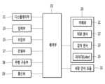
도 2는 본 발명의 제1 실시 예에 따른 로봇의 제어 블록도이다.
도 3은 본 발명의 제2 실시 예에 따른 로봇의 제어 블록도이다.
도 4는 본 발명의 실시 예에 따른 로봇이 동작하는 방법을 나타내는 순서도이다.
도 5는 본 발명의 제1 실시 예에 따른 안내 대상인 오브젝트를 설정하는 방법을 설명하기 위한 예시 도면이다.
도 6은 본 발명의 제2 실시 예에 따른 안내 대상인 오브젝트를 설정하는 방법을 설명하기 위한 예시 도면이다.
도 7은 본 발명의 일 실시 예에 따른 안내 대상인 오브젝트를 변경 또는 추가하는 방법을 설명하기 위한 예시 도면이다.
도 8 내지 도 9는 본 발명의 일 실시 예에 따른 장애물을 설명하기 위한 예시 도면이다.
도 10은 본 발명의 일 실시 예에 따른 오브젝트를 인식하는 방법을 설명하기 위한 예시 도면이다.
도 11은 본 발명의 제1 실시 예에 따른 카메라의 시야 범위에 오브젝트가 포함되는지 판단하는 방법을 나타내는 예시 도면이다.
도 12는 본 발명의 제2 실시 예에 따른 카메라의 시야 범위에 오브젝트가 포함되는지 판단하는 방법을 나타내는 예시 도면이다.
도 13은 본 발명에 따른 로봇이 오브젝트를 재인식하는 방법을 설명하기 위한 도면이다.
도 14 내지 도 15는 본 발명의 실시 예에 따른 오브젝트 및 동적 장애물의 이동 경로를 예측하는 방법을 설명하기 위한 도면이다.
도 16은 본 발명의 실시 예에 따른 로봇이 영상의 블러를 최소화하도록 이동 경로를 재설정하는 방법을 설명하기 위한 도면이다.1 is an exemplary view showing the appearance of a robot according to an embodiment of the present invention.
2 is a control block diagram of a robot according to a first embodiment of the present invention.
3 is a control block diagram of a robot according to a second embodiment of the present invention.
4 is a flowchart illustrating a method of operating a robot according to an embodiment of the present invention.
5 is an exemplary diagram for explaining a method of setting an object to be guided according to the first embodiment of the present invention.
6 is an exemplary view for explaining a method of setting an object to be guided according to a second embodiment of the present invention.
7 is an exemplary view for explaining a method of changing or adding an object to be guided according to an embodiment of the present invention.
8 to 9 are exemplary diagrams for explaining obstacles according to an embodiment of the present invention.
10 is an exemplary diagram for explaining a method of recognizing an object according to an embodiment of the present invention.
11 is an exemplary view illustrating a method of determining whether an object is included in a field of view of a camera according to a first embodiment of the present invention.
12 is an exemplary diagram illustrating a method of determining whether an object is included in a field of view of a camera according to a second embodiment of the present invention.
13 is a diagram for explaining a method of re-recognizing an object by a robot according to the present invention.
14 to 15 are diagrams for explaining a method of predicting a movement path of an object and a dynamic obstacle according to an embodiment of the present invention.
16 is a diagram for explaining a method of resetting a movement path by a robot according to an embodiment of the present invention to minimize blur of an image.
이하에서는 본 발명의 구체적인 실시 예를 도면과 함께 상세히 설명하도록 한다. 도면 부호에 관계없이 동일하거나 유사한 구성요소는 동일한 참조 번호를 부여하고 이에 대한 중복되는 설명은 생략하기로 한다. 이하의 설명에서 사용되는 구성요소에 대한 접미사 "모듈" 및 "부"는 명세서 작성의 용이함만이 고려되어 부여되거나 혼용되는 것으로서, 그 자체로 서로 구별되는 의미 또는 역할을 갖는 것은 아니다. 또한, 본 명세서에 개시된 실시 예를 설명함에 있어서 관련된 공지 기술에 대한 구체적인 설명이 본 명세서에 개시된 실시 예의 요지를 흐릴 수 있다고 판단되는 경우 그 상세한 설명을 생략한다. 또한, 첨부된 도면은 본 명세서에 개시된 실시 예를 쉽게 이해할 수 있도록 하기 위한 것일 뿐, 첨부된 도면에 의해 본 명세서에 개시된 기술적 사상이 제한되지 않으며, 본 발명의 사상 및 기술 범위에 포함되는 모든 변경, 균등물 내지 대체물을 포함하는 것으로 이해되어야 한다.Hereinafter, specific embodiments of the present invention will be described in detail with drawings. Regardless of the reference numerals, the same or similar components are given the same reference numerals, and overlapping descriptions thereof will be omitted. The suffixes "module" and "unit" for components used in the following description are given or used together in consideration of ease of writing the specification, and do not have meanings or roles that are distinct from each other by themselves. In addition, in describing the embodiments disclosed in this specification, if it is determined that a detailed description of a related known technology may obscure the gist of the embodiment disclosed in this specification, the detailed description thereof will be omitted. In addition, the accompanying drawings are only for easy understanding of the embodiments disclosed in this specification, the technical idea disclosed in this specification is not limited by the accompanying drawings, and all changes included in the spirit and technical scope of the present invention , it should be understood to include equivalents or substitutes.
도 1은 본 발명의 실시 예에 따른 로봇의 모습을 나타내는 예시 도면이고, 도 2는 본 발명의 제1 실시 예에 따른 로봇의 제어 블록도이고, 도 3은 본 발명의 제2 실시 예에 따른 로봇의 제어 블록도이다.1 is an exemplary diagram showing the appearance of a robot according to an embodiment of the present invention, FIG. 2 is a control block diagram of a robot according to a first embodiment of the present invention, and FIG. 3 is a diagram according to a second embodiment of the present invention. It is a control block diagram of the robot.
본 발명의 실시 예에 따른 로봇(1)은 디스플레이부(11), 입력부(13), 저장부(15), 전원부(17), 주행 구동부(18), 통신부(19), 영상 인식부(20), 사람 인식 모듈(31) 및 제어부(33)의 전부 또는 일부를 포함할 수 있다. 또는, 로봇(1)은 앞에서 나열한 구성요소 외에 다른 구성요소를 더 포함할 수도 있다.The
도 1을 참고하면, 로봇(1)은 입력부(13)가 구비된 상부 모듈과, 디스플레이부(11) 및 주행 구동부(18)가 구비된 하부 모듈을 포함할 수 있다.Referring to FIG. 1 , the
입력부(13)는 사용자로부터 입력명령을 수신할 수 있다. 예를 들어, 입력부(13)는 길 안내를 요청하기 위한 입력 명령 또는 목적지를 설정하는 입력 명령 등을 수신할 수 있다.The
디스플레이부(11)는 적어도 하나 이상의 정보를 표시할 수 있다. 예를 들어, 디스플레이부(11)는 목적지의 위치, 목적지까지의 이동 경로, 목적지까지 예상 소요 시간, 또는 전방에 위치한 장애물 정보 등을 표시할 수 있다.The
주행 구동부(18)는 로봇(1)을 사방으로 이동시킬 수 있다. 주행 구동부(18)는 설정된 이동 경로를 따라 이동하거나, 또는 설정된 목적지까지 이동하도록 구동될 수 있다.The
로봇(1)의 전방은 입력부(13)가 위치한 방향일 수 있고, 로봇(1)은 전방으로 이동할 수 있다.The front of the
한편, 입력부(13)가 구비된 상부 모듈은 수평 방향으로 회전이 가능할 수 있다. 로봇(1)은 입력부(13)를 통해 목적지 입력 명령을 수신하면, 도 1에 도시된 바와 같은 상태에서 상부 모듈이 180도 회전하여 전방으로 이동할 수 있고, 사용자는 로봇(1)의 후방에 위치하게 된 디스플레이부(11)를 보면서 목적지까지 안내 정보를 제공받을 수 있다. 이를 통해, 로봇(1)은 안내 대상인 사용자를 목적지까지 동행하여 이동 경로를 안내할 수 있다.Meanwhile, the upper module equipped with the
그러나, 도 1에 도시된 로봇의 형상은 예시적인 것으로, 이에 제한될 필요는 없다.However, the shape of the robot shown in FIG. 1 is exemplary and does not need to be limited thereto.
디스플레이부(11)는 다양한 정보를 표시할 수 있다. 디스플레이부(11)는 사용자에게 목적지까지 이동 경로를 안내하기 위해 필요한 적어도 하나 이상의 정보를 표시할 수 있다.The
입력부(13)는 사용자로부터 적어도 하나 이상의 입력 명령을 수신할 수 있다. 입력부(13)는 입력 명령을 수신하기 위한 터치 패널을 포함할 수 있고, 동시에 출력 정보를 표시하기 위한 모니터를 더 포함할 수 있다.The
저장부(15)는 로봇(1)의 운행에 필요한 데이터를 저장할 수 있다. 구체적인 예를 들면, 저장부(15)는 로봇(1)의 주행 경로를 산출하기 위한 데이터, 디스플레이부(11) 또는 입력부(13)에 정보를 출력하기 위한 데이터, 사람 또는 사물을 인식하기 위한 알고리즘 등의 데이터 등을 저장할 수 있다.The
로봇(1)이 정해진 공간 내에 주행하도록 설정된 경우, 저장부(15)는 정해진 공간의 맵(map) 정보를 저장하고 있을 수 있다. 예를 들어, 로봇(1)이 공항(airport) 내에서 이동하도록 설정된 경우, 저장부(15)는 공항의 맵 정보를 저장하고 있을 수 있다.When the
전원부(17)는 로봇(1)의 구동을 위한 전원을 공급할 수 있다. 전원부(17)는 디스플레이부(11), 입력부(13) 및 제어부(33) 등에 전원을 공급할 수 있다.The
전원부(17)는 배터리 드라이버(battery Driver) 및 리튬-이온 배터리(Li-Ion Battery)를 포함할 수 있다. 배터리 드라이버는 리튬-이온 배터리의 충전과 방전을 관리할 수 있고, 리튬-이온 배터리는 공항 로봇의 구동을 위한 전원을 공급할 수 있다. 리튬-이온 배터리는 24V/102A 리튬-이온 배터리 2개를 병렬로 연결하여 구성될 수 있다.The
주행 구동부(18)는 모터 드라이버(Motor Drivers), 휠 모터 및 회전 모터를 포함할 수 있다. 모터 드라이버는 로봇의 구동을 위한 휠 모터 및 회전 모터를 구동하는 역할을 수행할 수 있고, 휠 모터는 로봇의 주행을 위한 복수 개의 바퀴를 구동시킬 수 있고, 회전 모터는 로봇의 메인 바디 또는 로봇의 헤드부의 좌우 회전, 상하 회전을 위해 구동되거나 로봇의 바퀴의 방향 전환 또는 회전을 위하여 구동될 수 있다.The
통신부(19)는 외부와 데이터를 송수신할 수 있다. 예를 들어, 통신부(19)는 변경 사항을 업데이트하기 위해 주기적으로 맵 정보를 수신할 수 있다. 또한, 통신부(19)는 사용자의 이동 단말기와 통신할 수 있다.The
영상 인식부(20)는 카메라(21)와, RGB 센서(22)와, 깊이 센서(Depth sensor, 23), 및 라이더(Lidar, 25) 중 적어도 하나 이상을 포함할 수 있다.The
영상 인식부(20)는 사람 및 사물을 검출할 수 있고, 검출된 사람 및 사물의 이동 정보를 획득할 수 있다. 이동 정보는 이동 방향과 이동 속도 등을 포함할 수 있다.The
특히, 본 발명의 제1 실시 예에 따르면, 영상 인식부(20)는 카메라(21), RGB 센서(22), 깊이 센서(23) 및 라이더(25)를 모두 포함할 수 있다. 반면에, 본 발명의 제2 실시 예에 따르면, 영상 인식부(20)는 카메라(21) 및 RGB 센서(22)만 포함할 수 있다. 이와 같이, 본 발명은 실시 예에 따라 영상 인식부(20)의 구성 요소가 상이할 수 있고, 영상 인식부(20)의 구성에 따라 오브젝트를 (재)인식하는 알고리즘이 상이하게 적용될 수 있으며, 이에 대한 설명은 후술하기로 한다.In particular, according to the first embodiment of the present invention, the
카메라(21)는 주변 영상을 촬영할 수 있다. 영상 인식부(20)는 적어도 하나 이상의 카메라(21)를 포함할 수 있다. 예를 들어, 영상 인식부(20)는 제1 카메라와 제2 카메라를 포함할 수 있고, 제1 카메라는 입력부(13)에 구비되고, 제2 카메라는 디스플레이부(11)에 구비될 수 있다. 카메라(21)는 사람 또는 사물을 포함하는 2차원 영상을 촬영할 수 있다.The
RGB 센서(22)는 영상에서 사람을 검출하기 위한 색상 성분을 추출할 수 있다. 구체적으로, RGB 센서(22)는 영상에 포함된 Red 성분, Green 성분, Blue 성분 각각을 추출할 수 있다. 로봇(1)은 RGB 센서(22)를 통해 사람 또는 사물을 인식하기 위한 색상 데이터를 획득할 수 있다.The
깊이 센서(23)는 영상의 깊이 정보를 검출할 수 있다. 로봇(1)은 깊이 센서(23)를 통해 영상에 포함된 사람 또는 사물과의 거리를 산출하기 위한 데이터를 획득할 수 있다.The depth sensor 23 may detect depth information of an image. The
라이더(25)는 레이저를 송신한 후 사람 또는 사물에서 반사되어 도달하는 시간을 측정하여 거리를 측정할 수 있다. 라이더(25)는 로봇(1)이 주행하는 동안 장애물과 부딪히지 않도록 사람 또는 사물과의 거리를 센싱한 데이터를 획득할 수 있다. 또한, 라이더(25)는 안내 대상인 사용자를 인식하기 위하여 주변에 위치한 오브젝트들을 인식하고, 인식된 오브젝트들과의 거리를 측정할 수 있다.The lidar 25 may measure the distance by measuring the time it takes for the laser beam to reach after being reflected from a person or object after transmitting the laser beam. The lidar 25 may acquire data obtained by sensing a distance to a person or object so that the
사람 인식 모듈(31)은 영상 인식부(20)를 통해 획득된 데이터를 이용하여 사람을 인식할 수 있다. 구체적으로, 사람 인식 모듈(31)은 영상 인식부(20)를 통해 인식된 사람의 외모를 구별할 수 있다. 따라서, 로봇(1)은 사람 인식 모듈(31)을 통해 주변에 위치한 적어도 하나 이상의 사람 중 안내 대상인 사용자를 식별할 수 있고, 안내 대상인 사용자의 위치, 거리 등을 획득할 수 있다.The
제어부(33)는 로봇(1)의 전반적인 동작을 제어할 수 있다. 제어부(33)는 로봇(1)을 구성하는 구성요소 각각을 제어할 수 있다. 구체적으로, 제어부(33)는 디스플레이부(11), 입력부(13), 저장부(15), 전원부(17), 주행 구동부(18), 통신부(19), 영상 인식부(20) 및 사람 인식 모듈(31) 중 적어도 하나 이상을 제어할 수 있다.The
다음으로, 도 4를 참조하여 본 발명의 실시 예에 따른 로봇이 동작하는 방법을 설명한다. 도 4는 본 발명의 실시 예에 따른 로봇이 동작하는 방법을 나타내는 순서도이다.Next, a method for operating a robot according to an embodiment of the present invention will be described with reference to FIG. 4 . 4 is a flowchart illustrating a method of operating a robot according to an embodiment of the present invention.
로봇(1)의 입력부(13)는 목적지 입력명령을 수신할 수 있다(S101).The
사용자는 입력부(13)를 통해 로봇(1)에 다양한 정보, 명령 등을 입력할 수 있고, 입력부(13)는 사용자로부터 정보, 명령 등을 수신할 수 있다.The user can input various information, commands, etc. to the
구체적으로, 사용자는 입력부(13)를 통해 경로 안내를 요청 하는 명령을 입력할 수 있고, 사용자가 안내받고자 하는 목적지 정보를 입력할 수 있다. 입력부(13)는 경로 안내 요청 신호를 수신하고, 목적지 정보를 수신할 수 있다. 예를 들어, 입력부(13)는 터치스크린으로 형성되며, 터치스크린에 표시된 '경로 안내 요청'을 나타내는 버튼을 선택하는 입력 명령을 수신할 수 있다. 또한, 입력부(13)는 목적지를 나타내는 복수개의 항목 중 어느 하나를 선택하는 명령을 수신하거나, 알파벳 또는 한글 자모를 나타내는 키 버튼을 통해 목적지 정보의 입력 명령을 수신할 수 있다.Specifically, the user may input a command for requesting route guidance through the
제어부(33)는 목적지 입력명령을 수신하면, 안내 대상에 해당하는 오브젝트를 설정할 수 있다(S103).Upon receiving a destination input command, the
로봇(1)은 경로 안내를 요청하는 명령을 수신하면, 목적지까지의 경로를 지도로 표시하거나 목적지까지 동행하여 경로를 안내할 수 있다.Upon receiving a command for requesting route guidance, the
제어부(33)는 목적지까지 동행하여 경로를 안내하는 경우 경로 안내를 요청한 사용자를 목적지까지 놓치지 않고 추적하여 안내하기 위하여, 경로 안내를 요청한 사용자를 안내 대상에 해당하는 오브젝트로 설정할 수 있다. When the
다음으로, 도 5 내지 도 6을 참조하여, 본 발명의 실시 예에 따른 제어부(33)가 안내 대상에 해당하는 오브젝트를 설정하는 방법을 설명한다.Next, with reference to FIGS. 5 and 6 , a method of setting an object corresponding to a guidance target by the
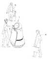
도 5는 본 발명의 제1 실시 예에 따른 안내 대상인 오브젝트를 설정하는 방법을 설명하기 위한 예시 도면이고, 도 6은 본 발명의 제2 실시 예에 따른 안내 대상인 오브젝트를 설정하는 방법을 설명하기 위한 예시 도면이다.5 is an exemplary diagram for explaining a method of setting an object as a guide target according to the first embodiment of the present invention, and FIG. 6 is an exemplary diagram for explaining a method of setting an object as a guide target according to the second embodiment of the present invention. This is an example drawing.
제1 실시 예에 따르면, 제어부(33)는 목적지 입력명령을 수신할 때 입력부(13)에 입력 중인 사용자를 안내 대상인 오브젝트로 설정할 수 있다. 구체적으로, 도 5를 참조하면, 제어부(33)는 입력부(13)를 통해 목적지의 입력 명령을 수신하면, 카메라(21)로 입력부(13)의 전방에 위치한 적어도 하나 이상의 사람을 포함하는 영상을 촬영할 수 있다. 제어부(33)는 촬영된 영상에 포함된 적어도 하나 이상의 사람을 안내 대상인 오브젝트로 설정할 수 있다.According to the first embodiment, when receiving a destination input command, the
제어부(33)는 목적지 입력명령을 수신할 때 촬영된 영상을 분석할 수 있다. 일 실시 예에 따르면, 제어부(33)는 RGB 센서(22) 및 깊이 센서(23) 중 적어도 하나 이상을 통해 촬영된 영상에서 적어도 하나 이상의 사람을 검출하고, 검출된 사람 중 적어도 하나를 안내 대상인 오브젝트로 설정할 수 있다.The
다른 실시 예에 따르면, 제어부(33)는 RGB 센서(22) 및 깊이 센서(23)로 촬영된 영상을 분석하는 동시에 라이더(25)를 통해 인접한 위치에 있는 사람을 검출할 수 있고, 검출된 사람 중 적어도 하나를 안내 대상인 오브젝트로 설정할 수 있다.According to another embodiment, the
제어부(33)는 촬영된 영상에서 검출된 사람 중 적어도 하나 이상을 안내 대상인 오브젝트로 설정할 수 있다.The
제어부(33)는 촬영된 영상에서 검출된 사람이 한 명이면, 검출된 한 명을 안내 대상인 오브젝트로 설정할 수 있다. 제어부(33)는 촬영된 영상에서 검출된 사람이 적어도 두 명 이상이면, 검출된 두 명 이상의 사람 중 한 명만을 안내 대상인 오브젝트로 설정할 수 있다.If there is only one person detected in the photographed image, the
특히, 제어부(33)는 촬영된 영상에서 검출된 사람 중 입력부(13)에 입력 중인 사람을 결정할 수 있다. 도 5에 도시된 예시를 참조하면, 제어부(33)는 입력부(13)를 통해 목적지 입력명령을 수신하면 로봇(1)과 인접한 영역에 위치한 적어도 하나 이상의 사람을 검출할 수 있다. 구체적으로, 제어부(33)는 카메라(21)로 촬영된 영상을 분석하여 사람을 검출하거나 라이더(25)로 레이저를 송출하여 입력부(13)로부터 제일 가까이에 있는 사람을 검출하거나, 카메라(21) 및 라이더(25)를 모두 이용하여 사람을 검출할 수 있다. 예를 들어, 제어부(33)는 제1 사람(P1)과 제2 사람(P2)을 검출할 수 있고, 검출된 제1 및 제2 사람(P1, P2) 중 입력부(13)에 입력 중인 제1 사람(P1)을 안내 대상인 오브젝트로 설정할 수 있다. 도 5에서 로봇(1)과 제1 사람(P1) 사이의 거리는 로봇(1)과 제2 사람(P2) 사이의 거리 보다 길 수 있으나, 제어부(33)는 입력부(33)에 입력 중인 제1 사람(P1)을 안내 대상인 오브젝트로 설정할 수 있다.In particular, the
제1 실시 예에 따르면, 로봇(1)은 안내 대상인 오브젝트 설정을 보다 정확하게 할 수 있는 이점이 있다.According to the first embodiment, the
제2 실시 예에 따르면, 제어부(33)는 목적지 입력명령을 수신할 때 로봇(1)과 가장 가까이에 위치한 사람을 안내 대상인 오브젝트로 설정할 수 있다.According to the second embodiment, when receiving a destination input command, the
일 실시 예에 따르면, 제어부(33)는 목적지 입력명령을 수신할 때 카메라(21)로 주변 영상을 촬영하여 RGB 센서(22)로 사람을 검출하고, 깊이 센서(23)로 검출된 사람과의 거리를 산출할 수 있다. 제어부(33)는 산출된 거리가 가장 짧은 사람을 안내 대상인 오브젝트로 설정할 수 있다.According to an embodiment, when receiving a destination input command, the
다른 실시 예에 따르면, 제어부(33)는 목적지 입력명령을 수신할 때 라이더(25)를 통해 인접한 위치에 있는 사람들을 검출할 수 있다. 제어부(33)는 라이더(25)를 통해 로봇(1)에 인접한 적어도 한 명 이상의 사람과의 거리를 산출하고, 산출된 거리가 가장 짧은 사람을 안내 대상이 오브젝트로 설정할 수 있다.According to another embodiment, the
또 다른 실시 예에 따르면, 제어부(33)는 목적지 입력명령을 수신할 때 카메라(21) 및 라이더(25)를 함께 이용하여 주변에 위치한 사람을 검출하고, 검출된 사람 중 로봇(1)과의 거리가 가장 가까운 사람을 안내 대상이 오브젝트로 설정할 수 있다.According to another embodiment, when receiving a destination input command, the
도 6에 도시된 예시를 참조하면, 제어부(33)는 목적지 입력명령을 수신할 때 제1 내지 제3 사람(P1, P2, P3)을 검출하고, 검출된 사람 중 로봇(1)과의 거리가 가장 가까운 제1 사람(P1)을 안내 대상인 오브젝트로 설정할 수 있다.Referring to the example shown in FIG. 6, the
제2 실시 예에 따르면, 로봇(1)은 보다 신속하게 안내 대상인 오브젝트의 설정이 가능하며, 오브젝트를 설정하는 알고리즘을 비교적 단순화시킬 수 있는 이점이 있다.According to the second embodiment, the
제3 실시 예에 따르면, 제어부(33)는 입력부(13)를 통해 오브젝트 선택 명령을 수신하여, 안내 대상인 오브젝트를 설정할 수 이다. 제어부(33)는 목적지 입력명령을 수신할 때 카메라(21)로 주변 영상을 촬영할 수 있다. 제어부(33)는 촬영된 주변 영상을 디스플레이부(11) 또는 터치스크린으로 형성된 입력부(13)에 출력할 수 있고, 출력된 영상에서 적어도 한 명 이상의 사람을 선택하는 오브젝트 선택 명령을 수신할 수 있다. 사용자는 디스플레이부(11) 또는 터치스크린으로 형성된 입력부(13)를 보고 본인 또는 본인을 포함한 적어도 한 명 이상의 일행을 입력부(13)로 선택할 수 있고, 선택된 본인 또는 본인을 포함한 일행을 안내 대상인 오브젝트로 설정할 수 있다.According to the third embodiment, the
제3 실시 예에 따르면, 로봇(1)은 사용자에 의해 선택된 사람을 오브젝트로 설정함으로써 오브젝트 설정의 정확도를 높이고, 사용자에게 안내 대상인 오브젝트를 자유롭게 선택하는 기능을 제공 가능한 이점이 있다.According to the third embodiment, the
제어부(33)는 제1 내지 제3 실시 예에서 복수의 사람을 안내 대상인 오브젝트로 설정할 수 있다. 예를 들어, 제1 실시 예에서, 제어부(33)는 카메라(21)로 촬영된 영상에서 입력부(13)를 쳐다보고 있는 사람을 검출하여, 검출된 적어도 하나 이상의 사람을 모두 안내 대상인 오브젝트로 설정할 수 있다. 제2 실시 예에서, 제어부(33)는 인접한 사람들과의 거리를 산출한 후 기준 거리 이내에 위치한 사람을 모두 안내 대상인 오브젝트로 설정할 수 있다. 제3 실시 예에서, 제어부(33)는 선택된 사람이 복수인 경우 선택된 복수의 사람을 모두 안내 대상인 오브젝트로 설정할 수 있다.The
그러나 앞에서 설명한 방법들은 예시적인 것에 불과하므로 이에 제한될 필요 없으며, 각 실시 예는 조합되어 안내 대상인 오브젝트가 설정될 수도 있다.However, since the methods described above are only examples, they do not need to be limited thereto, and each embodiment may be combined to set an object to be guided.
한편, 제어부(33)는 안내 대상인 오브젝트를 설정하는 도중에 오브젝트의 인식이 어려운 상태를 감지할 수 있다. 제어부(33)는 오브젝트의 인식이 어려운 상태를 감지하면, 안내 대상인 오브젝트를 변경하거나 추가할 수 있다.Meanwhile, the
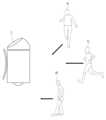
도 7은 본 발명의 일 실시 예에 따른 안내 대상인 오브젝트를 변경 또는 추가하는 방법을 설명하기 위한 예시 도면이다.7 is an exemplary view for explaining a method of changing or adding an object to be guided according to an embodiment of the present invention.
앞에서 설명한 바와 같은 방식으로, 제어부(33)는 안내 대상인 오브젝트를 설정할 수 있다. 예를 들어, 도 7의 (a)에 도시된 바와 같이, 제어부(33)는 카메라로 촬영된 영상에서 제1 타깃(T1)을 안내 대상인 오브젝트로 인식하고, 설정할 수 있다.In the same manner as described above, the
한편, 제어부(33)가 오브젝트를 인식 및 설정을 완료하기까지 소정 시간이 소요될 수 있고, 그 사이에 사람들은 이동할 수 있다. 예를 들어, 도 7의 (b)에 도시된 바와 같이, 로봇(1)과 제1 타깃(T1) 사이의 거리가 로봇(1)과 다른 사람 사이의 거리 보다 길어지거나 같아질 수 있고, 도 7의 (c)에 도시된 바와 같이 제1 타깃(T1)의 얼굴이 가려져 오브젝트의 인식이 불가할 수 있다. 그러나, 도 7에 도시된 상황은 예시적인 것에 불과하며, 제1 타깃(T1)이 빠르게 이동하거나, 다른 사람에 의해 가려지거나, 고개를 회전하는 등의 이유로 오브젝트 인식을 실패하는 경우를 모두 포함할 수 있다.Meanwhile, it may take a predetermined amount of time for the
이 경우, 제어부(33)는 제1 타깃(T1)을 제외한 다른 사람 중 제2 타깃(T2)을 인식하여 안내 대상인 오브젝트를 제1 타깃(T1)에서 제2 타깃(T2)으로 변경 설정하거나, 제1 타깃(T1)과 함께 제2 타깃(T2)을 추가하여 오브젝트로 설정할 수 있다. 제어부(33)가 제2 타깃(T2)을 인식하는 방법은 제1 타깃(T1)을 인식하는 방법과 동일할 수 있고, 앞에서 설명한 바와 같으므로 자세한 설명은 생략하기로 한다.In this case, the
이와 같이, 본 발명의 실시 예에 따르면, 제어부(33)는 오브젝트를 도중에 변경하거나, 추가할 수 있어 오브젝트의 인식 및 설정이 실패하는 경우를 방지할 수 있다.In this way, according to an embodiment of the present invention, the
제어부(33)는 안내 대상에 해당하는 오브젝트의 설정을 완료하면, 설정된 오브젝트를 나타내는 이미지를 디스플레이부(11)에 출력할 수 있다.When the setting of the object corresponding to the guide target is completed, the
또한, 제어부(33)는 설정된 오브젝트를 나타내는 이미지와 함께 오브젝트가 제대로 설정되었는지 확인하는 메시지를 디스플레이부(11)에 출력할 수 있다. 사용자는 디스플레이부(11)에 출력된 오브젝트를 참고한 후 입력부(13)에 오브젝트를 재설정하기 위한 명령 또는 목적지 안내 시작 명령을 입력할 수 있다. 제어부(33)는 오브젝트를 재설정하기 위한 명령이 입력되면 앞에서 설명한 적어도 하나 이상의 실시 예를 통해 오브젝트를 재설정할 수 있고, 목적지 안내 시작 명령을 수신하면 설정된 오브젝트를 추적하며 경로 안내를 시작할 수 있다.In addition, the
다시, 도 4를 설명한다.Again, Fig. 4 will be described.
제어부(33)는 오브젝트를 설정하고, 입력명령에 따른 목적지까지의 이동 경로를 설정할 수 있다(S105).The
실시 예에 따라, 오브젝트를 설정하는 단계(S103)와, 이동 경로를 설정하는 단계(S105)의 순서는 변경될 수 있다.Depending on the embodiment, the order of setting the object (S103) and setting the movement path (S105) may be changed.
저장부(15)는 로봇(1)이 위치한 장소의 맵(map) 정보를 저장하고 있을 수 있다. 또는, 저장부(15)는 로봇(1)이 이동 경로를 안내 가능한 영역의 맵 정보를 저장하고 있을 수 있다. 예를 들어, 로봇(1)은 공항 내에서 길을 안내하는 로봇일 수 있고, 이 경우 저장부(15)는 공항의 맵 정보를 저장하고 있을 수 있다. 그러나, 이는 예시적인 것에 불과하므로 이에 제한될 필요는 없다.The
통신부(19)는 GPS(Global Positioning System)를 포함할 수 있고, GPS를 통해 현재 위치를 인식할 수 있다.The
제어부(33)는 저장부(15)에 저장된 맵 정보, 통신부(19)를 통해 인식한 현재 위치 및 입력부(13)를 수신한 목적지를 이용하여 목적지까지의 안내 경로를 획득할 수 있다.The
제어부(33)는 복수개의 안내 경로를 획득할 수 있다. 일 실시 예에 따르면, 제어부(33)는 복수 개의 안내 경로 중 최단 거리를 갖는 안내 경로를 목적지까지의 이동 경로로 설정할 수 있다. 다른 실시 예에 따르면, 제어부(33)는 통신부(19)를 통해 다른 구역의 혼잡도 정보를 수신할 수 있고, 복수 개의 안내 경로 중 혼잡도가 가장 낮은 안내 경로를 목적지까지의 이동 경로로 설정할 수 있다. 또 다른 실시 예에 따르면, 제어부(33)는 복수개의 안내 경로를 디스플레이부(11)에 출력한 후 입력부(13)를 통해 선택되는 안내 경로를 목적지까지의 이동 경로로 설정할 수 있다.The
제어부(33)는 설정된 이동 경로를 따라 주행할 수 있다(S107).The
제어부(33)는 설정된 이동 경로를 따라 주행하는 경우 이동 속도를 낮게 조절할 수 있다. 구체적으로, 제어부(33)는 목적지까지 이동 경로를 설정하여 안내 모드로 동작하는 경우 제1 이동 속도로 주행하고, 안내 모드가 종료한 후 자율 주행하는 경우 제2 이동 속도로 주행하도록 제어하고, 제1 이동 속도는 제2 이동 속도 보다 느릴 수 있다.The
제어부(33)는 전방에 위치하는 장애물 및 설정된 오브젝트를 인식할 수 있다(S109).The
제어부(33)는 주행하면서 로봇(1)의 전방에 위치하는 장애물을 인식할 수 있다. 한편, 제어부(33)는 로봇(1)의 전방뿐만 아니라 로봇(1)의 주변에 위치하는 장애물을 모두 인식할 수 있다.The
여기서, 장애물은 로봇(1)의 주행에 방해가 되는 장애물과, 설정된 오브젝트의 이동에 방해가 되는 장애물을 모두 포함할 수 있고, 정적 장애물과 동적 장애물을 포함할 수 있다.Here, the obstacles may include both obstacles obstructing the driving of the
로봇(1)의 주행에 방해가 되는 장애물은 로봇(1)과 부딪힐 가능성이 기 설정된 기준 이상인 장애물로, 예를 들어, 로봇(1)의 전방에서 이동하는 사람 또는 로봇(1)의 이동 경로에 위치한 기둥 등의 사물을 포함할 수 있다.Obstacles obstructing the driving of the
마찬가지로, 설정된 오브젝트의 이동에 방해가 되는 장애물은 오브젝트와 부딪힐 가능성이 기 설정된 기준 이상인 장애물로, 예를 들어, 오브젝트의 이동 경로와 이동 속도를 고려할 때 부딪힐 가능성이 높은 사람 또는 사물을 포함할 수 있다.Similarly, obstacles obstructing the movement of a set object are obstacles that are more likely to collide with the object than a predetermined standard, and may include, for example, people or objects that are highly likely to be hit when considering the movement path and movement speed of the object. can
정적 장애물은 고정된 위치에 존재하는 장애물로, 저장부(15)에 저장된 맵 정보에 포함된 장애물일 수 있다. 즉, 정적 장애물은 맵 정보로 저장되어 있는 장애물로 로봇(1) 또는 설정된 오브젝트의 이동이 어려운 사물을 의미할 수 있다.The static obstacle is an obstacle existing at a fixed position and may be an obstacle included in map information stored in the
동적 장애물은 로봇(1) 또는 설정된 오브젝트의 전방에서 이동 중이거나, 또는 이동 예정인 사람과 사물일 수 있다. 즉, 동적 장애물은 맵 정보 등으로 저장되어 있지 않으나, 카메라(21) 또는 라이더(25) 등으로 인식된 장애물을 의미할 수 있다.The dynamic obstacle may be a person or object that is moving or is scheduled to move in front of the
다음으로, 도 8 내지 도 9는 본 발명의 일 실시 예에 따른 장애물을 설명하기 위한 예시 도면이다.Next, FIGS. 8 and 9 are exemplary diagrams for explaining obstacles according to an embodiment of the present invention.
도 8을 참조하면, 제어부(33)는 맵 정보(M)를 이용하여 이동 경로(P1)를 설정할 수 있다. 저장부(15)는 맵 정보(M)를 저장하고 있을 수 있고, 맵 정보(M)는 정적 장애물(O1)에 대한 정보를 포함할 수 있다. 제어부(33)는 이동 경로(P1)를 따라 주행하면서 맵 정보(M)에 저장된 정적 장애물(O1)을 인식할 수 있다.Referring to FIG. 8 , the
또한, 제어부(33)는 영상 인식부(20)를 통해 동적 장애물(O2)에 대한 정보를 획득할 수 있다. 동적 장애물(O2)에 대한 정보는 로봇(1)의 현재 위치를 기준으로 소정 거리 내에 위치한 장애물만 획득 가능할 수 있다. 동적 장애물을 인식할 수 있는 거리는 영상 인식부(20)를 구성하는 각 구성요소의 성능에 따라 달라질 수 있다.Also, the
도 9에 도시된 이미지는 카메라(21)로 촬영된 영상에 정적 장애물(O1)과 동적 장애물(O2)의 인식 결과를 나타내는 것으로, 인식에 실패한 사람 또는 사물(X2)이 있을 수도 있다. 로봇(1)은 주행하면서 도 9에 도시된 바와 같은 장애물 인식 동작을 계속해서 수행할 수 있다.The image shown in FIG. 9 shows the result of recognizing the static obstacle O1 and the dynamic obstacle O2 in the image captured by the
또한, 제어부(33)는 주행하면서 설정된 오브젝트를 인식할 수 있다.Also, the
일 실시 예에 따르면, 제어부(33)는 카메라(21)로 주변 영상을 촬영하여 주변에 위치한 사람을 검출하고, 검출된 사람 중 설정된 오브젝트와 일치하는 사람을 식별하여 오브젝트를 인식할 수 있다. 제어부(33)는 오브젝트를 인식하여 오브젝트의 이동을 추적할 수 있다.According to an embodiment, the
다른 실시 예에 따르면, 제어부(33)는 카메라(21)로 오브젝트를 인식하는 동시에, 라이더(25)로 오브젝트와 떨어진 거리를 산출하면서 오브젝트를 인식 및 추적할 수 있다.According to another embodiment, the
도 10은 본 발명의 일 실시 예에 따른 오브젝트를 인식하는 방법을 설명하기 위한 예시 도면이다.10 is an exemplary diagram for explaining a method of recognizing an object according to an embodiment of the present invention.
도 10을 참조하면, 제어부(33)는 맵 정보(M)와 영상 인식부(20)에 기초하여, 정적 장애물(O1)과 동적 장애물(O2)을 인식할 수 있다. 도 10에 도시된 화살표는 로봇(1)의 이동 방향일 수 있다. 도 10에 도시된 시야 범위(V)는 카메라(21)의 시야(Field of View)를 나타낼 수 있다. 한편, 카메라(21)를 포함하는 영상 인식부(20)는 회전이 가능하여, 로봇(1)의 이동 방향뿐만 아니라 다른 방향에 대한 장애물 인식도 가능하다.Referring to FIG. 10 , the
또한, 제어부(33)는 로봇(1)의 이동 방향과 반대 방향에 위치한 오브젝트(T)를 인식할 수 있다. 일 실시 예에 따르면, 제어부(33)는 회전하는 카메라(21)를 통해 장애물(O1, O2)과 함께 오브젝트(T)를 인식할 수 있다. 즉, 카메라(21)로 로봇(1)의 주변을 촬영하고, 촬영된 영상에서 검출된 사람 중 설정된 오브젝트를 식별하여 오브젝트(T)를 인식할 수 있다.In addition, the
다른 실시 예에 따르면, 회전하는 라이더(25) 또는 디스플레이부(11) 방향에 구비된 라이더(25)를 통해 로봇(1)과 인접한 영역에서 감지되는 타깃들을 서칭(searching)하고, 서칭된 타깃 중 카메라(21)로 촬영된 영상 정보를 통해 오브젝트를 설정할 수 있다. 제어부(33)는 라이더(25)로 설정된 오브젝트와의 거리를 계속해서 인식함으로써, 인식되는 거리 정보를 통해 오브젝트(T)의 이동울 추적할 수 있다.According to another embodiment, targets detected in an area adjacent to the
장애물(O1, O2) 및 오브젝트(T)를 인식하는 방법은 앞에서 설명한 방법 외에 다른 방법을 더 포함할 수 있고, 조합하여 실시되는 것도 가능하다.The method of recognizing the obstacles O1 and O2 and the object T may further include methods other than the methods described above, and may be implemented in combination.
다시, 도 4를 설명한다.Again, Fig. 4 will be described.
제어부(33)는 오브젝트가 시야 범위에 위치하는지 판단할 수 있다(S111).The
제어부(33)는 오브젝트가 시야 범위에 위치하지 않는 것으로 판단되면, 오브젝트가 시야 범위에 포함되도록 복귀 모션을 수행할 수 있다(S112).If it is determined that the object is not located in the viewing range, the
일 실시 예에 따르면, 제어부(33)는 회전하는 카메라(21)를 이동 방향과 반대 방향에 위치시킨 후 카메라의 시야 범위에 오브젝트가 포함되는지 판단할 수 있다. 다른 실시 예에 따르면, 제어부(33)는 디스플레이부(11)에 구비된 카메라(21)의 시야 범위에 오브젝트가 포함되는지 판단할 수 있다.According to an embodiment, the
한편, 제어부(33)가 카메라(21)의 시야 범위에 오브젝트가 포함되는지 판단하는 방법은 영상 인식부(20)를 구성하는 구성 요소에 따라 달라질 수 있다.Meanwhile, a method for the
도 11은 본 발명의 제1 실시 예에 따른 카메라의 시야 범위에 오브젝트가 포함되는지 판단하는 방법을 나타내는 예시 도면이고, 도 12는 본 발명의 제2 실시 예에 따른 카메라의 시야 범위에 오브젝트가 포함되는지 판단하는 방법을 나타내는 예시 도면이다.11 is an exemplary diagram illustrating a method of determining whether an object is included in the field of view of a camera according to a first embodiment of the present invention, and FIG. 12 is an exemplary view showing an object included in a field of view of a camera according to a second embodiment of the present invention. It is an exemplary diagram showing a method of determining whether
먼저, 제1 실시 예에 따르면, 영상 인식부(20)는 카메라(21), RGB 센서(22), 깊이 센서(23) 및 라이더(25)를 포함할 수 있다. 제어부(33)는 카메라(21)로 로봇(1)의 이동 방향과 반대 방향의 영상을 촬영하고, RGB 센서(22)로 사람을 검출하고, 깊이 센서(23)로 검출된 사람이 로봇(1)과 떨어진 거리 정보를 획득하도록 제어할 수 있다. 또한, 제어부(33)는 라이더(25)로 오브젝트와의 거리를 추출하도록 제어할 수 있다.First, according to the first embodiment, the
따라서, 제어부(33)는 오브젝트를 설정할 때 거리 정보와 오브젝트 이미지를 통해 기준 크기 정보를 획득하고, 오브젝트를 추적할 때 라이더(25)로 획득한 거리 정보 및 현재 촬영된 오브젝트 이미지를 통해 현재 크기 정보를 획득할 수 있고, 기준 크기 정보와 현재 크기 정보를 비교하여 오브젝트가 카메라(21)의 시야 범위를 벗어나는지 판단할 수 있다. 즉, 제어부(33)는 기준 크기 정보와 현재 크기 정보의 차가 기 설정된 크기 이상이면 오브젝트가 카메라(21)의 시야 범위를 벗어난 것으로 판단하고, 기 설정된 크기 미만이면 오브젝트는 카메라(21)의 시야 범위에 포함된 것으로 판단할 수 있다. 또한, 제어부(33)는 촬영된 영상에서 오브젝트가 식별되지 않는 경우에도, 오브젝트는 카메라(21)의 시야 범위에 포함된 것으로 판단할 수 있다.Therefore, the
제1 실시 예에서, 제어부(33)는 오브젝트가 카메라(21)의 시야 범위에 위치하지 않는 것으로 판단되면, 라이더(25)를 통해 추적한 오브젝트가 카메라(21)의 시야 범위에 포함되도록 회전 및/또는 이동하는 복귀 모션을 수행할 수 있다.In the first embodiment, if it is determined that the object is not located in the field of view of the
그 결과, 도 11(a)에 도시된 바와 같이 설정된 오브젝트(T1)가 카메라의 시야 범위를 벗어나더라도, 복귀 모션에 의해 도 11(b)에 도시된 바와 같이 오브젝트(T1)가 카메라의 시야 범위에 포함되어 오브젝트를 놓치는 경우를 최소화할 수 있다.As a result, even if the object T1 set as shown in FIG. 11 (a) is out of the camera's field of view, the object T1 is moved out of the camera's field of view as shown in FIG. 11 (b) by the return motion. It can minimize the case of missing an object by being included in .
제2 실시 예에 따르면, 영상 인식부(20)는 카메라(21) 및 RGB 센서(22)만 포함할 수 있고, 이 경우 제어부(33)는 촬영된 영상에서 오브젝트를 식별하여 오브젝트가 카메라(21)의 시야 범위에 포함되는지 판단할 수 있다. 예를 들어, 제어부(33)는 오브젝트의 팔, 허리, 다리 등을 인식하여 카메라(21)의 시야 범위에 포함되는지 판단하고, 팔, 허리 또는 다리 등 중 적어도 하나가 포함되지 않으면 오브젝트는 카메라(21)의 시야 범위에 포함된 것으로 판단할 수 있다.According to the second embodiment, the
오브젝트에서 인식하는 팔, 허리, 다리 등의 요소는 예시적인 것에 불과하며, 제어부(33)는 오브젝트를 인식하기 위한 요소를 디폴트로 설정하고 있거나, 입력부(13)를 통해 사용자로부터 입력명령을 수신하여 설정할 수 있다.Elements such as arms, waists, and legs recognized by objects are merely examples, and the
제2 실시 예에서, 제어부(33)는 오브젝트가 카메라(21)의 시야 범위에 위치하지 않는 것으로 판단되면, 현재까지 측정한 오브젝트의 이동 속도와 방향 및 장애물 정보를 활용하여 회전 및/또는 이동하는 복귀 모션을 수행할 수 있다.In the second embodiment, if it is determined that the object is not located within the viewing range of the
예를 들어, 제어부(33)는 오브젝트의 설정 요소(예를 들어, 팔, 허리, 다리)가 모두 카메라(21)의 시야 범위에 포함되도록 복귀 모션을 수행할 수 있다.For example, the
그 결과, 도 12(a)에 도시된 바와 같이 설정된 오브젝트(T1)가 카메라의 시야 범위를 벗어나더라도, 도 12(b)에 도시된 바와 같이 복귀 모션에 의해 오브젝트의 설정 요소가 카메라(21)의 시야 범위에 모두 포함될 수 있다.As a result, even if the object T1 set as shown in FIG. 12 (a) is out of the camera's field of view, as shown in FIG. may be included in the field of view of
제어부(33)는 설정된 오브젝트가 시야 범위에 위치하지 않는 경우, 설정된 오브젝트를 재인식할 수 있다(S113).When the set object is not located in the viewing range, the
제어부(33)는 카메라(21)를 회전시키거나, 주행 구동부(18)를 통해 로봇(1)을 회전시켜 로봇(1) 주위의 영상을 촬영할 수 있고, 촬영된 영상에서 오브젝트를 인식할 수 있다.The
도 13은 본 발명에 따른 로봇이 오브젝트를 재인식하는 방법을 설명하기 위한 도면이다.13 is a diagram for explaining a method of re-recognizing an object by a robot according to the present invention.
제어부(33)는 오브젝트를 인식하는 경우 딥러닝 기반의 Matching Network 알고리즘을 이용할 수 있다. Matching Network 알고리즘은 영상에서 검출된 사람의 색상(color), 외형(shape), 무늬(texture), 엣지(edge) 등의 다양한 데이터 성분을 추출하고, 추출된 데이터 성분을 Matching Network에 통과시켜 feature vector를 획득할 수 있다. 획득된 feature vector를 안내 대상인 오브젝트와 비교하여 유사도를 산출함으로써 오브젝트를 재인식할 수 있다. Matching Network는 공지의 기술인 바 이에 대한 자세한 설명은 생략하기로 한다.When recognizing an object, the
제어부(33)는 도 13의 (a)에 도시된 바와 같이 검출된 사람에서 두 개의 데이터 성분을 추출하여 Matching Network 알고리즘을 적용하거나, 도 13의 (b)에 도시된 바와 같이 검출된 사람에서 세 개의 데이터 성분을 추출하여 Matching Network 알고리즘을 적용할 수 있다. 그러나, 이는 예시적인 것에 불과하며, 제어부(33)는 적어도 하나 이상의 데이터 성분을 추출하여 Matching Network 알고리즘을 적용할 수 있다.The
다시, 도 4를 설명한다.Again, Fig. 4 will be described.
제어부(33)는 오브젝트의 예상 경로와 장애물의 예상 경로에 교차점이 존재하는지 판단할 수 있다(S115).The
제어부(33)는 장애물과 오브젝트의 충돌 가능성을 산출하고, 장애물과 오브젝트의 충돌이 예상되면 이동 경로를 재설정하도록 제어할 수 있다.The
구체적으로, 제어부(33)는 영상 인식부(20)를 통해 오브젝트의 이동 정보와, 주변에 위치한 동적 장애물의 이동 정보를 획득할 수 있고, 저장부(15)에 저장된 맵 정보를 통해 정적 장애물 정보를 획득할 수 있다.Specifically, the
제어부(33)는 오브젝트와 동적 장애물들은 정적 장애물을 마주하면, 정적 장애물을 피해 이동하는 것으로 예상할 수 있다. 따라서, 제어부(33)는 오브젝트의 이동 방향 및 이동 속도와, 동적 장애물의 이동 방향 및 이동 속도를 예측할 수 있다.When the object and the dynamic obstacles encounter the static obstacle, the
도 14 내지 도 15는 본 발명의 실시 예에 따른 오브젝트 및 동적 장애물의 이동 경로를 예측하는 방법을 설명하기 위한 도면이다.14 to 15 are diagrams for explaining a method of predicting a movement path of an object and a dynamic obstacle according to an embodiment of the present invention.
제어부(33)는 로봇(1)의 주변에 위치한 오브젝트(T1)와, 제1 동적 장애물(P1) 및 제2 동적 장애물(P2)을 인식할 수 있다. 또한, 제어부(33)는 오브젝트(T1)의 이동 방향 및 이동 속도와, 제1 동적 장애물(P1)의 이동 방향 및 이동 속도와, 제2 동적 장애물(P2)의 이동 방향 및 이동 속도를 예측할 수 있다.The
도 14에 도시된 예시를 참고하면, 오브젝트(T1)와 P1의 이동 방향이 일치함을 확인할 수 있다. 또한, 도 15에 도시된 예시를 참고하면, 화살표는 오브젝트 또는 동적 장애물의 예측되는 이동 방향 및 이동 속도를 나타내는 예측 경로로, 오브젝트(T1)의 예상 경로와 제1 동적 장애물(P1)의 예상 경로에 교차점이 존재하는 것으로 판단할 수 있다.Referring to the example shown in FIG. 14 , it can be confirmed that the moving directions of the object T1 and P1 coincide. In addition, referring to the example shown in FIG. 15 , arrows are predicted paths indicating the predicted moving direction and moving speed of the object or dynamic obstacle, and the predicted path of the object T1 and the predicted path of the first dynamic obstacle P1. It can be determined that there is an intersection in .
제어부(33)는 오브젝트와 예상 경로와 장애물의 예상 경로에 교차점이 존재하면 오브젝트와 장애물이 부딪힐 가능성이 높은 것으로 판단하고, 오브젝트와 예상 경로와 장애물의 예상 경로에 교차점이 존재하지 않으면 오브젝트와 장애물이 부딪힐 가능성이 낮은 것으로 판단할 수 있다.The
제어부(33)는 오브젝트와 예상 경로와 장애물의 예상 경로에 교차점이 존재하면, 오브젝트의 예상 경로가 장애물의 예상 경로와 교차되지 않도록 이동 경로를 재설정할 수 있다(S117).If there is an intersection between the expected path of the object and the expected path of the obstacle, the
예를 들어, 제어부(33)는 장애물의 예상 경로와 소정 거리 이상 떨어진 영역으로 이동하도록 이동 경로를 재설정할 수 있다. 그러나, 이는 예시적인 것에 불과하며, 제어부(33)는 다양한 방법으로 는 오브젝트와 예상 경로와 장애물의 예상 경로에 교차점이 존재하지 않도록 이동 경로를 재설정할 수 있다.For example, the
또는, 제어부(33)는 오브젝트의 예상 경로와 장애물의 예상 경로와 교차되지 않도록 이동 속도를 빠르게 또는 느리게 조절할 수 있다.Alternatively, the
또는, 제어부(33)는 '충돌 예상'을 나타내는 경고 메시지를 디스플레이부(11)에 출력함으로써, 오브젝트가 장애물과 부딪히는 경우를 최소화할 수 있다.Alternatively, the
한편, 제어부(33)는 오브젝트와 예상 경로와 장애물의 예상 경로에 교차점이 존재하지 않는 경우, 영상의 블러(Blur)가 예상되는지 판단할 수 있다(S119).Meanwhile, when there is no intersection between the expected path of the object and the expected path of the obstacle, the
단계 S115와 단계 S119의 순서는 변경될 수 있다.The order of steps S115 and S119 may be changed.
영상의 블러(Blur)란 영상이 흐릿하여 오브젝트 또는 장애물의 인식이 어려운 상태를 의미할 수 있다. 영상의 블러는 로봇이 회전하거나, 또는 로봇, 오브젝트 또는 장애물이 빠르게 이동하는 등의 경우에 발생할 수 있다.Blur of an image may mean a state in which it is difficult to recognize an object or an obstacle because the image is blurry. Image blur may occur when a robot rotates or when a robot, an object, or an obstacle moves rapidly.
제어부(33)는 정적 장애물 또는 동적 장애물을 회피하기 위하여 회전 이동하는 경우 영상의 블러가 발생할 것으로 예상할 수 있다. 또한, 제어부(33)는 로봇, 오브젝트 또는 장애물의 이동 속도가 기 설정된 기준 속도 이상으로 감지되면 영상의 블러가 발생할 것으로 예상할 수 있다.When the
따라서, 제어부(33)는 이동 경로 상에서 존재하는 회전 모션의 횟수와, 회전 각도 및 예상 이동 속도 등을 산출하여 영상의 블러 발생 가능성을 산출할 수 있다.Therefore, the
제어부(33)는 영상의 블러가 예상되면, 영상의 블러가 최소화되도록 이동 경로를 재설정할 수 있다(S121).If blurring of the image is expected, the
제어부(33)는 영상의 블러 발생 가능성이 기 설정된 기준 이상이면 이동 경로를 재설정하도록 제어할 수 있다.The
일 실시 예에 따르면, 제어부(33)는 이동 경로까지의 길이 대비 예상되는 영상의 블러 발생 횟수를 통해 영상의 블러 발생 가능성을 산출할 수 있다. 예를 들어, 제어부(33)는 이동 경로를 재설정하는 기준을 10%로 설정하고 있을 수 있다, 제어부(33)는 이동 경로의 길이가 500m이고, 예상되는 영상의 블러 발생 횟수가 5회이면, 영상의 블러 발생 가능성을 1%로 산출할 수 있고, 이 경우 이동 경로를 변경하지 않을 수 있다. 반면에, 제어부(33)는 이동 경로의 길이가 100m이고, 예상되는 영상의 블러 발생 횟수가 20회이면, 영상의 블러 발생 가능성을 20%로 산출할 수 있고, 이 경우 이동 경로를 재설정할 수 있다. 그러나, 앞에서 예시로 든 수치는 설명의 편의를 위해 예시로 든 것에 불과하므로 이에 제한될 필요는없다.According to an embodiment, the
다른 실시 예에 따르면, 제어부(33)는 이동 경로까지의 길이와 관계 없이 예상되는 영상의 블러 발생 횟수가 기준 횟수 이상이면 영상의 블러가 발생할 것으로 예상할 수 있다. 예를 들어, 제어부(33)는 이동 경로를 재설정하는 기준을 5회로 설정하고 있을 수 있고, 예상되는 영상의 블러 발생 횟수가 3회이면 이동 경로를 변경하지 않고, 예상되는 영상의 블러 발생 횟수가 7회이면 이동 경로를 재설정할 수 있다. 그러나, 앞에서 예시로 든 수치는 설명의 편의를 위해 예시로 든 것에 불과하므로 이에 제한될 필요는 없다.According to another embodiment, the
제어부(33)는 로봇(1)의 회전 횟수를 최소화하거나 회전 각도가 작은 이동 경로로 재설정하거나, 로봇 또는 오브젝트의 이동 속도를 줄이는 방향으로 이동 경로를 재설정할 수 있다.The
도 16은 본 발명의 실시 예에 따른 로봇이 영상의 블러를 최소화하도록 이동 경로를 재설정하는 방법을 설명하기 위한 도면이다.16 is a diagram for explaining a method of resetting a movement path by a robot according to an embodiment of the present invention to minimize blur of an image.
도 16을 참조하면, 로봇(1)은 주행하면서 장애물을 인식할 수 있고, 이동 경로(P1) 상에 적어도 하나 이상의 동적 장애물이(O2)이 위치함을 인식할 수 있다. 도 16을 참조하면, 제어부(33)는 이동 경로(P1) 상에 위치한 세 개의 동적 장애물(O2)을 회피하기 위하여 세 번의 회전 이동을 예상할 수 있고, 이에 따라 블러의 발생을 예측할 수 있다.Referring to FIG. 16 , the
이 경우, 제어부(33)는 다른 안내 경로에 따른 장애물을 인식할 수 있고, 다른 안내 경로에 따를 경우 영상의 블러 발생 가능성이 더 낮은 것으로 판단되면 이동 경로를 다른 안내 경로(P2)로 재설정할 수 있다.In this case, the
이와 같이, 제어부(33)가 영상의 블러 발생이 최소화되도록 이동 경로를 재설정하면 안내 대상인 오브젝트를 놓치는 경우를 최소화할 수 있는 이점이 있다.In this way, if the
한편, 도 4에서는 영상의 블러 발생을 예측하여 이를 최소화하는 방향으로 이동 경로를 재설정하는 방법만을 설명하였으나, 본 발명의 실시 예에 따른 제어부(33)는 오브젝트가 장애물에 의해 가려져 오브젝트의 인식을 실패하는 경우를 최소화하도록 이동 경로를 재설정할 수도 있다.Meanwhile, in FIG. 4, only a method of predicting blurring of an image and resetting a moving path in a direction of minimizing it has been described, but the
다시, 도 4를 설명한다.Again, Fig. 4 will be described.
S117 또는 S121에서 이동 경로를 재설정하면, 단계 S107로 돌아가 재설정된 이동 경로를 따라 로봇이 이동하도록 주행할 수 있다.If the movement path is reset in S117 or S121, the robot may travel to move along the reset movement path by returning to step S107.
한편, S111에서 오브젝트가 시야 범위에 위치하는 경우 제어부(33)는 로봇(1)이 목적지에 도달하였는지 판단할 수 있다(S123).On the other hand, when the object is located in the viewing range in S111, the
로봇(1)이 목적지에 도달하지 않은 경우, 단계 S107로 돌아가 이동 경로를 따라 로봇이 이동하도록 주행할 수 있다.If the
한편, 제어부(33)는 로봇(1)이 목적지에 도달한 경우에는 목적지 안내 동작을 종료할 수 있다(S125).Meanwhile, when the
즉, 제어부(33)는 안내 동작을 종료하고 목적지 없이 자율 주행을 하거나, 안내 동작을 시작했던 원래 위치로 돌아갈 수 있다. 그러나, 이는 예시적인 것에 불과하므로 이에 제한될 필요는 없다.That is, the
본 발명의 일 실시 예에 의하면, 전술한 방법은, 프로그램이 기록된 매체에 프로세서가 읽을 수 있는 코드로서 구현하는 것이 가능하다. 프로세서가 읽을 수 있는 매체의 예로는, ROM, RAM, CD-ROM, 자기 테이프, 플로피 디스크, 광 데이터 저장장치 등이 있다.According to an embodiment of the present invention, the above-described method can be implemented as a processor-readable code in a medium on which a program is recorded. Examples of media readable by the processor include ROM, RAM, CD-ROM, magnetic tape, floppy disk, optical data storage, and the like.
상기와 같이 설명된 로봇은 상기 설명된 실시 예들의 구성과 방법이 한정되게 적용될 수 있는 것이 아니라, 상기 실시 예들은 다양한 변형이 이루어질 수 있도록 각 실시 예들의 전부 또는 일부가 선택적으로 조합되어 구성될 수도 있다.The robot described above is not limited to the configuration and method of the above-described embodiments, but the above embodiments may be configured by selectively combining all or part of each embodiment so that various modifications can be made. there is.
Claims (10)
Translated fromKorean맵(map) 정보를 저장하는 저장부;
상기 수신된 목적지까지의 이동 경로를 상기 맵 정보에 기초하여 설정하는 제어부;
상기 설정된 이동 경로를 따라 이동하는 주행 구동부; 및
상기 목적지까지 이동하는 동안 안내 대상에 해당하는 오브젝트를 인식하는 영상 인식부를 포함하고,
상기 영상 인식부는
주변에 위치한 사람 또는 사물과의 거리를 센싱하는 라이더를 포함하고,
상기 제어부는
상기 라이더를 통해 로봇에 인접하게 위치한 적어도 하나 이상의 사람과의 거리를 센싱하고, 상기 로봇으로부터 가장 가까이 위치한 사람을 상기 오브젝트로 설정하며,
상기 오브젝트가 시야 범위에 포함되지 않으면 상기 오브젝트가 시야 범위에 포함되도록 이동 또는 회전하고, 상기 오브젝트를 재인식하고,
상기 이동 경로 상에 포함된 회전 모션의 횟수 또는 회전 각도에 기초하여 영상의 블러(blur) 발생 가능성을 산출하고, 상기 영상의 블러 발생 가능성이 기 설정된 기준 이상이면 회전 모션의 횟수를 최소화하는 안내 경로 또는 회전 각도가 작은 안내 경로로 이동 경로를 재설정하는 로봇.an input unit that receives a destination input command;
a storage unit for storing map information;
a control unit configured to set a movement route to the received destination based on the map information;
a driving driving unit that moves along the set movement path; and
An image recognition unit recognizing an object corresponding to a guidance target while moving to the destination;
The image recognition unit
Including a rider that senses the distance to a person or object located nearby,
The control unit
Sensing a distance to at least one person located adjacent to the robot through the rider, and setting a person closest to the robot as the object;
If the object is not included in the viewing range, the object is moved or rotated so that it is included in the viewing range, and the object is re-recognized;
A guide path that calculates the possibility of blurring of an image based on the number of rotational motions or the rotational angle included in the movement path, and minimizes the number of rotational motions when the probability of blurring of the image is greater than or equal to a preset standard. Or a robot that reroutes its movement with a guide path with a small rotation angle.
상기 영상 인식부는
상기 로봇의 주변 영상을 촬영하는 카메라와,
상기 촬영된 영상에서 사람을 검출하기 위한 색상 성분을 추출하는 RGB 센서를 포함하는 로봇.According to claim 1,
The image recognition unit
A camera for capturing an image around the robot;
A robot including an RGB sensor for extracting a color component for detecting a person from the photographed image.
상기 제어부는
상기 목적지 입력명령을 수신하면 상기 카메라로 상기 입력부의 전방 영상을 촬영하고, 상기 촬영된 영상에서 목적지를 입력 중인 사람을 상기 오브젝트로 설정하는 로봇.According to claim 2,
The control unit
When receiving the destination input command, the robot captures a front image of the input unit with the camera, and sets a person inputting a destination as the object in the captured image.
상기 제어부는
상기 오브젝트를 설정하는 동안 오브젝트의 인식을 실패하면 다른 영상에 포함된 다른 사람을 상기 오브젝트로 변경 설정 또는 추가 설정하는 로봇.According to claim 1 or 3,
The control unit
A robot that changes or additionally sets another person included in another image to the object if the recognition of the object fails while setting the object.
상기 영상 인식부는
상기 목적지까지 이동하는 동안 장애물을 인식하고,
상기 제어부는
상기 장애물과 상기 오브젝트의 충돌 가능성을 산출하고, 상기 장애물과 상기 오브젝트의 충돌이 예상되면 상기 이동 경로를 재설정하는 로봇.According to claim 1,
The image recognition unit
Recognize obstacles while moving to the destination,
The control unit
A robot that calculates a possibility of collision between the obstacle and the object, and resets the movement path when a collision between the obstacle and the object is expected.
상기 장애물은
상기 맵 정보에 포함된 정적 장애물과, 상기 영상 인식부를 통해 인식되는 동적 장애물을 포함하는 로봇.According to claim 6,
the obstacle
A robot including a static obstacle included in the map information and a dynamic obstacle recognized through the image recognizing unit.
상기 제어부는
상기 장애물의 예상 경로와 상기 오브젝트의 예상 경로를 산출하고, 상기 장애물의 예상 경로와 상기 오브젝트의 예상 경로에 교차점이 존재하는지 판단하여 상기 장애물과 상기 오브젝트의 충돌 여부를 판단하는 로봇.
According to claim 6,
The control unit
A robot that calculates an expected path of the obstacle and an expected path of the object, and determines whether an intersection between the expected path of the obstacle and the expected path of the object exists to determine whether the obstacle collides with the object.
Priority Applications (3)
| Application Number | Priority Date | Filing Date | Title |
|---|---|---|---|
| KR1020180001516AKR102500634B1 (en) | 2018-01-05 | 2018-01-05 | Guide robot and operating method thereof |
| US16/495,270US20200089252A1 (en) | 2018-01-05 | 2018-01-17 | Guide robot and operating method thereof |
| PCT/KR2018/000818WO2019135437A1 (en) | 2018-01-05 | 2018-01-17 | Guide robot and operation method thereof |
Applications Claiming Priority (1)
| Application Number | Priority Date | Filing Date | Title |
|---|---|---|---|
| KR1020180001516AKR102500634B1 (en) | 2018-01-05 | 2018-01-05 | Guide robot and operating method thereof |
Publications (2)
| Publication Number | Publication Date |
|---|---|
| KR20190083727A KR20190083727A (en) | 2019-07-15 |
| KR102500634B1true KR102500634B1 (en) | 2023-02-16 |
Family
ID=67144220
Family Applications (1)
| Application Number | Title | Priority Date | Filing Date |
|---|---|---|---|
| KR1020180001516AActiveKR102500634B1 (en) | 2018-01-05 | 2018-01-05 | Guide robot and operating method thereof |
Country Status (3)
| Country | Link |
|---|---|
| US (1) | US20200089252A1 (en) |
| KR (1) | KR102500634B1 (en) |
| WO (1) | WO2019135437A1 (en) |
Families Citing this family (12)
| Publication number | Priority date | Publication date | Assignee | Title |
|---|---|---|---|---|
| TWI695180B (en)* | 2018-07-24 | 2020-06-01 | 國立交通大學 | Robot guiding method |
| US10909225B2 (en)* | 2018-09-17 | 2021-02-02 | Motorola Mobility Llc | Electronic devices and corresponding methods for precluding entry of authentication codes in multi-person environments |
| JP7683482B2 (en)* | 2019-10-03 | 2025-05-27 | ソニーグループ株式会社 | Data processing device, data processing method, and mobile body |
| KR102857593B1 (en)* | 2020-01-29 | 2025-09-08 | 한화에어로스페이스 주식회사 | Mobile surveillance apparatus and operation method thereof |
| JP7450481B2 (en)* | 2020-07-14 | 2024-03-15 | 本田技研工業株式会社 | Mobile object control device, mobile object, mobile object control method, and program |
| KR20220083100A (en)* | 2020-12-11 | 2022-06-20 | 삼성전자주식회사 | Robot and method for controlling thereof |
| JP7736438B2 (en)* | 2021-03-22 | 2025-09-09 | 日本電気株式会社 | system |
| CN113524190B (en)* | 2021-07-26 | 2022-07-29 | 深圳市优必选科技股份有限公司 | Robot foot end collision stability control method and device and foot type robot |
| KR20230031044A (en)* | 2021-08-26 | 2023-03-07 | 삼성전자주식회사 | Robot and controlling method thereof |
| KR102704531B1 (en)* | 2021-12-06 | 2024-09-09 | 네이버 주식회사 | Method and system for controlling serving robots |
| CN115229821A (en)* | 2022-07-14 | 2022-10-25 | 深圳优地科技有限公司 | Hotel robot distribution method and device and hotel robot |
| US20240142985A1 (en)* | 2022-10-28 | 2024-05-02 | Zebra Technologies Corporation | De-centralized traffic-aware navigational planning for mobile robots |
Citations (2)
| Publication number | Priority date | Publication date | Assignee | Title |
|---|---|---|---|---|
| KR101140984B1 (en)* | 2010-12-29 | 2012-05-03 | 고려대학교 산학협력단 | Safe path generating method considering appearance of invisible dynamic obstacle which is visibly occluded |
| US20160188977A1 (en)* | 2014-12-24 | 2016-06-30 | Irobot Corporation | Mobile Security Robot |
Family Cites Families (8)
| Publication number | Priority date | Publication date | Assignee | Title |
|---|---|---|---|---|
| JP4072033B2 (en)* | 2002-09-24 | 2008-04-02 | 本田技研工業株式会社 | Reception guidance robot device |
| EP2050544B1 (en)* | 2005-09-30 | 2011-08-31 | iRobot Corporation | Robot system with wireless communication by TCP/IP transmissions |
| JP4528295B2 (en)* | 2006-12-18 | 2010-08-18 | 株式会社日立製作所 | GUIDANCE ROBOT DEVICE AND GUIDANCE SYSTEM |
| KR20160000162A (en)* | 2014-06-24 | 2016-01-04 | 주식회사 네오텍 | Self moving method of service robot |
| KR101940718B1 (en)* | 2015-09-04 | 2019-01-22 | 한국전자통신연구원 | Apparatus and method for extracting person domain based on RGB-Depth image |
| EP3223034B1 (en)* | 2016-03-16 | 2022-07-20 | Ricoh Company, Ltd. | Object detection apparatus and moveable apparatus |
| CN105796289B (en)* | 2016-06-03 | 2017-08-25 | 京东方科技集团股份有限公司 | Blind-guidance robot |
| US10001780B2 (en)* | 2016-11-02 | 2018-06-19 | Brain Corporation | Systems and methods for dynamic route planning in autonomous navigation |
- 2018
- 2018-01-05KRKR1020180001516Apatent/KR102500634B1/enactiveActive
- 2018-01-17USUS16/495,270patent/US20200089252A1/ennot_activeAbandoned
- 2018-01-17WOPCT/KR2018/000818patent/WO2019135437A1/ennot_activeCeased
Patent Citations (2)
| Publication number | Priority date | Publication date | Assignee | Title |
|---|---|---|---|---|
| KR101140984B1 (en)* | 2010-12-29 | 2012-05-03 | 고려대학교 산학협력단 | Safe path generating method considering appearance of invisible dynamic obstacle which is visibly occluded |
| US20160188977A1 (en)* | 2014-12-24 | 2016-06-30 | Irobot Corporation | Mobile Security Robot |
Also Published As
| Publication number | Publication date |
|---|---|
| WO2019135437A1 (en) | 2019-07-11 |
| US20200089252A1 (en) | 2020-03-19 |
| KR20190083727A (en) | 2019-07-15 |
Similar Documents
| Publication | Publication Date | Title |
|---|---|---|
| KR102500634B1 (en) | Guide robot and operating method thereof | |
| CN106104203B (en) | A kind of distance detection method of mobile object, device and aircraft | |
| JP5782708B2 (en) | Driving support device | |
| US7873448B2 (en) | Robot navigation system avoiding obstacles and setting areas as movable according to circular distance from points on surface of obstacles | |
| KR102224157B1 (en) | Moving robot system comprising moving robot and charging station | |
| KR20190134554A (en) | Method of identifying dynamic obstacle and robot implementing thereof | |
| JP6771588B2 (en) | Moving body and control method of moving body | |
| JP2018147337A (en) | Autonomous Mobile Robot, Autonomous Mobile Robot Control Method and Control Program | |
| US10068141B2 (en) | Automatic operation vehicle | |
| JP6919882B2 (en) | Person estimation system and estimation program | |
| US10067511B2 (en) | Automatic operation vehicle | |
| CN110293965B (en) | Parking method and control device, vehicle-mounted device and computer readable medium | |
| JP2012045706A (en) | Device and method of preventing collision for remote control of mobile robot | |
| US11801602B2 (en) | Mobile robot and driving method thereof | |
| JP2007199965A (en) | Autonomous mobile device | |
| KR20210015126A (en) | Moving Robot | |
| JP7641799B2 (en) | Information processing device, mobile object control device, information processing device control method, mobile object control method, and program | |
| KR101455236B1 (en) | Mobile apparatus for providing augmented reality and method thereof | |
| KR101140558B1 (en) | Autonomous mobile robot and control method for the same | |
| CN107203206A (en) | Unmanned traveling Operation Van | |
| KR102275083B1 (en) | Robotic systems and a returning method of robot for automatic charging | |
| KR102163462B1 (en) | Path-finding Robot and Mapping Method Using It | |
| US12235658B2 (en) | Information processing device, information processing system, method, and program | |
| KR20210000153A (en) | Method of acquiring image for position recognition and robot implementing thereof | |
| JP2022050115A (en) | Movable body position estimation system, operator terminal device, and position estimation method |
Legal Events
| Date | Code | Title | Description |
|---|---|---|---|
| PA0109 | Patent application | St.27 status event code:A-0-1-A10-A12-nap-PA0109 | |
| PG1501 | Laying open of application | St.27 status event code:A-1-1-Q10-Q12-nap-PG1501 | |
| PN2301 | Change of applicant | St.27 status event code:A-3-3-R10-R13-asn-PN2301 St.27 status event code:A-3-3-R10-R11-asn-PN2301 | |
| A201 | Request for examination | ||
| PA0201 | Request for examination | St.27 status event code:A-1-2-D10-D11-exm-PA0201 | |
| P22-X000 | Classification modified | St.27 status event code:A-2-2-P10-P22-nap-X000 | |
| D13-X000 | Search requested | St.27 status event code:A-1-2-D10-D13-srh-X000 | |
| D14-X000 | Search report completed | St.27 status event code:A-1-2-D10-D14-srh-X000 | |
| E902 | Notification of reason for refusal | ||
| PE0902 | Notice of grounds for rejection | St.27 status event code:A-1-2-D10-D21-exm-PE0902 | |
| AMND | Amendment | ||
| E13-X000 | Pre-grant limitation requested | St.27 status event code:A-2-3-E10-E13-lim-X000 | |
| P11-X000 | Amendment of application requested | St.27 status event code:A-2-2-P10-P11-nap-X000 | |
| P13-X000 | Application amended | St.27 status event code:A-2-2-P10-P13-nap-X000 | |
| PE0601 | Decision on rejection of patent | St.27 status event code:N-2-6-B10-B15-exm-PE0601 | |
| AMND | Amendment | ||
| E13-X000 | Pre-grant limitation requested | St.27 status event code:A-2-3-E10-E13-lim-X000 | |
| P11-X000 | Amendment of application requested | St.27 status event code:A-2-2-P10-P11-nap-X000 | |
| P13-X000 | Application amended | St.27 status event code:A-2-2-P10-P13-nap-X000 | |
| PX0901 | Re-examination | St.27 status event code:A-2-3-E10-E12-rex-PX0901 | |
| PX0701 | Decision of registration after re-examination | St.27 status event code:A-3-4-F10-F13-rex-PX0701 | |
| X701 | Decision to grant (after re-examination) | ||
| GRNT | Written decision to grant | ||
| PR0701 | Registration of establishment | St.27 status event code:A-2-4-F10-F11-exm-PR0701 | |
| PR1002 | Payment of registration fee | St.27 status event code:A-2-2-U10-U11-oth-PR1002 Fee payment year number:1 | |
| PG1601 | Publication of registration | St.27 status event code:A-4-4-Q10-Q13-nap-PG1601 | |
| P22-X000 | Classification modified | St.27 status event code:A-4-4-P10-P22-nap-X000 |