KR102499402B1 - Chirp noise generation device and method for compression pulse signal - Google Patents
Chirp noise generation device and method for compression pulse signalDownload PDFInfo
- Publication number
- KR102499402B1 KR102499402B1KR1020210042987AKR20210042987AKR102499402B1KR 102499402 B1KR102499402 B1KR 102499402B1KR 1020210042987 AKR1020210042987 AKR 1020210042987AKR 20210042987 AKR20210042987 AKR 20210042987AKR 102499402 B1KR102499402 B1KR 102499402B1
- Authority
- KR
- South Korea
- Prior art keywords
- signal
- noise
- received signal
- phase
- chirp
- Prior art date
- Legal status (The legal status is an assumption and is not a legal conclusion. Google has not performed a legal analysis and makes no representation as to the accuracy of the status listed.)
- Active
Links
- 238000000034methodMethods0.000titleclaimsdescription15
- 230000006835compressionEffects0.000title1
- 238000007906compressionMethods0.000title1
- 238000004458analytical methodMethods0.000claimsabstractdescription24
- 230000002194synthesizing effectEffects0.000claimsabstractdescription5
- 230000004044responseEffects0.000claimsabstractdescription3
- 238000005070samplingMethods0.000claimsdescription6
- 230000005540biological transmissionEffects0.000abstractdescription5
- 230000003321amplificationEffects0.000description2
- 230000015572biosynthetic processEffects0.000description2
- 238000010586diagramMethods0.000description2
- 230000006870functionEffects0.000description2
- 238000003199nucleic acid amplification methodMethods0.000description2
- 238000003786synthesis reactionMethods0.000description2
- 238000001514detection methodMethods0.000description1
- 230000000694effectsEffects0.000description1
- 238000012986modificationMethods0.000description1
- 230000004048modificationEffects0.000description1
- 230000003472neutralizing effectEffects0.000description1
Images


Classifications
- H—ELECTRICITY
- H04—ELECTRIC COMMUNICATION TECHNIQUE
- H04K—SECRET COMMUNICATION; JAMMING OF COMMUNICATION
- H04K3/00—Jamming of communication; Counter-measures
- H04K3/40—Jamming having variable characteristics
- H04K3/44—Jamming having variable characteristics characterized by the control of the jamming waveform or modulation type
- H—ELECTRICITY
- H04—ELECTRIC COMMUNICATION TECHNIQUE
- H04K—SECRET COMMUNICATION; JAMMING OF COMMUNICATION
- H04K3/00—Jamming of communication; Counter-measures
- H04K3/40—Jamming having variable characteristics
- H04K3/45—Jamming having variable characteristics characterized by including monitoring of the target or target signal, e.g. in reactive jammers or follower jammers for example by means of an alternation of jamming phases and monitoring phases, called "look-through mode"
- H—ELECTRICITY
- H04—ELECTRIC COMMUNICATION TECHNIQUE
- H04K—SECRET COMMUNICATION; JAMMING OF COMMUNICATION
- H04K3/00—Jamming of communication; Counter-measures
- H04K3/40—Jamming having variable characteristics
- H04K3/46—Jamming having variable characteristics characterized in that the jamming signal is produced by retransmitting a received signal, after delay or processing
- H—ELECTRICITY
- H04—ELECTRIC COMMUNICATION TECHNIQUE
- H04K—SECRET COMMUNICATION; JAMMING OF COMMUNICATION
- H04K3/00—Jamming of communication; Counter-measures
- H04K3/80—Jamming or countermeasure characterized by its function
- H04K3/82—Jamming or countermeasure characterized by its function related to preventing surveillance, interception or detection
- H04K3/827—Jamming or countermeasure characterized by its function related to preventing surveillance, interception or detection using characteristics of target signal or of transmission, e.g. using direct sequence spread spectrum or fast frequency hopping
- H—ELECTRICITY
- H04—ELECTRIC COMMUNICATION TECHNIQUE
- H04K—SECRET COMMUNICATION; JAMMING OF COMMUNICATION
- H04K2203/00—Jamming of communication; Countermeasures
- H04K2203/10—Jamming or countermeasure used for a particular application
- H04K2203/24—Jamming or countermeasure used for a particular application for communication related to weapons
Landscapes
- Engineering & Computer Science (AREA)
- Computer Networks & Wireless Communication (AREA)
- Signal Processing (AREA)
- Radar Systems Or Details Thereof (AREA)
Abstract
Translated fromKoreanDescription
Translated fromKorean본 발명은 압축펄스신호에 대응한 첩잡음 발생 장치 및 방법에 관한 것이다.The present invention relates to an apparatus and method for generating chirp noise corresponding to a compressed pulse signal.
전자전(electronic warfare)은 적의 전파사용을 탐지, 이용, 방해하고 아군의 전자파 사용을 보정하기 위한 전자에너지의 사용과 관련된 군사활동이다. 전자전의 수행기능 중 한 분야로서 적의 전투능력을 파괴, 무력화, 감소시킬 의도로 적의 지휘통제, 통신, 전자무기체계에 대하여 전파를 사용하거나 전자파를 직접 조사하는 전자공격(electronic attack)이 있다. 예를 들어, 표적의 반사 신호인 에코신호를 수신하여 표적을 추적하는 레이더에 대응하여 레이더의 추적을 방해하기 위한 다양한 형태의 전자공격이 수행될 수 있다.Electronic warfare is a military activity involving the use of electromagnetic energy to detect, exploit, and disrupt enemy use of radio waves and to compensate for friendly use of electromagnetic waves. As one of the functions performed by electronic warfare, there is an electronic attack that uses radio waves or directly irradiates electromagnetic waves against the enemy's command and control, communication, and electronic weapons systems with the intention of destroying, neutralizing, or reducing the enemy's combat capability. For example, in response to a radar tracking a target by receiving an echo signal, which is a reflection signal of the target, various types of electronic attacks may be performed to disrupt radar tracking.
전자공격은 크게 잡음(또는 잡음재밍) 및 기만의 형태로 분류될 수 있다. 전자공격 기법이 잡음인 경우, 잡음발생판을 사용하여 전자공격을 수행할 수 있다. 잡음은 절대적인 기준이 아닌 상대적 기준에 의해 협대역과 광대역으로 나누어질 수 있다. 전자공격 기법이 기만인 경우, 디지털 주파수 메모리(Digital Radio Frequency Memory, DRFM)를 사용하여 전자공격을 수행할 수 있다. 디지털 주파수 메모리는 기만뿐만 아니라 일정한 대역폭 내에서 임의의 주파수로 변경하면서 잡음을 생성하기도 한다.Electronic attacks can be largely classified into forms of noise (or noise jamming) and deception. If the electronic attack technique is noise, an electronic attack can be performed using a noise generator. Noise can be divided into narrowband and wideband based on a relative criterion rather than an absolute criterion. If the electronic attack technique is deception, an electronic attack may be performed using a digital radio frequency memory (DRFM). Digital frequency memory not only deceives, but also creates noise while changing to a random frequency within a certain bandwidth.
디지털 주파수 메모리는 LSFR(Linear Feedback Shift Register)를 이용하여 일정시간 동안에 하나의 주파수의 잡음을 생성하기 때문에 생성하고자 하는 대역폭까지는 일정시간이 요구된다. 따라서, 디지털 주파수 메모리에서 위협신호에 대응한 잡음을 발생할 때 일정한 시간이 요구되는 단점이 있다.Since the digital frequency memory generates noise of one frequency for a certain period of time using a Linear Feedback Shift Register (LSFR), a certain amount of time is required to reach the desired bandwidth. Therefore, there is a disadvantage in that a certain time is required when generating noise corresponding to the threat signal in the digital frequency memory.
본 발명이 해결하고자 하는 기술적 과제는 상기와 같은 종래 기술들이 갖고 있는 문제점을 해결하기 위한 것으로, 단일 펄스 내에서 잡음을 발생할 수 있는 첩잡음 발생 장치 및 방법을 제공함에 있다.A technical problem to be solved by the present invention is to solve the problems of the prior art as described above, and to provide an apparatus and method for generating noise within a single pulse.
본 발명이 해결하고자 하는 기술적 과제는 상기에서 언급한 것으로 제한되지 않으며, 언급되지 않은 또 다른 해결하고자 하는 과제는 아래의 기재들로부터 본 발명이 속하는 통상의 지식을 가진 자에 의해 명확하게 이해될 수 있을 것이다.The technical problems to be solved by the present invention are not limited to those mentioned above, and other problems to be solved that are not mentioned can be clearly understood by those skilled in the art from the following descriptions. There will be.
본 발명의 일 실시예에 따른 압축펄스신호에 대응한 첩잡음 발생 장치는 수신안테나, 상기 수신안테나를 통해 입력된 수신신호를 분석하여 전자공격 수행 여부를 판단하는 신호분석부, 및 상기 신호분석부로부터 상기 전자공격 수행이 필요하다는 제어명령이 수신되면 상기 수신안테나를 통해 입력된 수신신호를 저장하고, 상기 수신신호를 이용하여 첩잡음을 생성하고, 상기 수신신호와 상기 첩잡음을 합성하여 재밍신호를 생성하고, 상기 재밍신호를 송신하는 디지털 주파수 저장부를 포함한다.An apparatus for generating spooky noise corresponding to a compressed pulse signal according to an embodiment of the present invention includes a reception antenna, a signal analysis unit that analyzes a reception signal input through the reception antenna to determine whether an electronic attack is performed, and the signal analysis unit When a control command indicating that the electronic attack needs to be performed is received from the receiver, the received signal input through the reception antenna is stored, and spooky noise is generated using the received signal, and the received signal and the spooky noise are synthesized to generate a jamming signal and a digital frequency storage unit for generating and transmitting the jamming signal.
상기 신호분석부는 상기 수신신호를 분석하여 상기 디지털 주파수 저장부에 펄스폭 및 첩잡음변조대역폭을 송신할 수 있다.The signal analyzer may analyze the received signal and transmit a pulse width and a chirp noise modulation bandwidth to the digital frequency storage unit.
상기 디지털 주파수 저장부는 상기 신호분석부로부터 수신한 상기 펄스폭과 상기 첩잡음변조대역폭을 기반으로 상기 첩잡음을 생성할 수 있다.The digital frequency storage unit may generate the chirp noise based on the pulse width received from the signal analysis unit and the chirp noise modulation bandwidth.
상기 디지털 주파수 저장부는 상기 수신신호의 위상과 상기 첩잡음의 위상을 합해서 상기 재밍신호를 생성할 수 있다.The digital frequency storage unit may generate the jamming signal by adding a phase of the received signal and a phase of the chirp noise.
상기 수신신호의 위상은 수학식
상기 디지털 주파수 저장부는 시간도메인에서 상기 수신신호와 상기 첩잡음을 곱하여 상기 재밍신호를 생성할 수 있다.The digital frequency storage unit may generate the jamming signal by multiplying the received signal and the chirp noise in the time domain.
상기 재밍신호의 주파수대역폭은 상기 수신신호의 주파수대역폭과 상기 첩잡음변조대역폭의 합과 동일할 수 있다.The frequency bandwidth of the jamming signal may be equal to the sum of the frequency bandwidth of the received signal and the chirp noise modulation bandwidth.
본 발명의 다른 실시예에 따른 압축펄스신호에 대응한 첩잡음 발생 방법은 수신안테나를 통해 입력된 수신신호의 분석 내용에 따른 첩잡음의 펄스폭 및 첩잡음변조대역폭을 수신하는 단계, 상기 펄스폭과 상기 첩잡음변조대역폭을 기반으로 첩잡음을 생성하는 단계, 및 상기 수신신호와 상기 첩잡음을 합성하여 재밍신호를 생성하고, 상기 재밍신호를 송신하는 단계를 포함한다.A method for generating chirp noise corresponding to a compressed pulse signal according to another embodiment of the present invention includes receiving a pulse width of chirp noise and a chirp noise modulation bandwidth according to analysis of a received signal input through a reception antenna, the pulse width and generating chirp noise based on the chirp noise modulation bandwidth, synthesizing the received signal and the chirp noise to generate a jamming signal, and transmitting the jamming signal.
상기 압축펄스신호에 대응한 첩잡음 발생 방법은 상기 수신신호를 분석하여 전자공격 수행 여부를 판단하는 단계, 및 상기 전자공격 수행이 필요하다는 제어명령에 따라 상기 수신신호를 저장하는 단계를 더 포함할 수 있다.The method for generating chirp noise corresponding to the compressed pulse signal may further include determining whether an electronic attack is performed by analyzing the received signal, and storing the received signal according to a control command indicating that the electronic attack needs to be performed. can
상기 수신신호의 위상과 상기 첩잡음의 위상을 합해서 상기 재밍신호를 생성할 수 있다.The jamming signal may be generated by adding a phase of the received signal and a phase of the chirp noise.
상기 수신신호의 위상은 수학식
시간도메인에서 상기 수신신호와 상기 첩잡음을 곱하여 상기 재밍신호를 생성할 수 있다.The jamming signal may be generated by multiplying the received signal and the chirp noise in the time domain.
상기 재밍신호의 주파수대역폭은 상기 수신신호의 주파수대역폭과 상기 첩잡음변조대역폭의 합과 동일할 수 있다.The frequency bandwidth of the jamming signal may be equal to the sum of the frequency bandwidth of the received signal and the chirp noise modulation bandwidth.
본 발명의 실시예에 따른 압축펄스신호에 대응한 첩잡음 발생 장치 및 방법은 수신신호를 이용하여 생선된 첩잡음을 수신신호와 합성하여 송신함으로써 레이더의 표적 탐지 및 추적을 효과적으로 방해할 수 있다.An apparatus and method for generating spooky noise corresponding to a compressed pulse signal according to an embodiment of the present invention can effectively interfere with radar target detection and tracking by combining the spooky noise generated using the received signal with the received signal and transmitting the same.
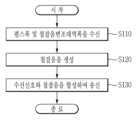
도 1은 본 발명의 일 실시예에 따른 압축펄스신호에 대응한 첩잡음 발생 장치를 나타내는 블록도이다.
도 2는 본 발명의 일 실시예에 따른 압축펄스신호에 대응한 첩잡음 발생 방법을 나타내는 흐름도이다.
도 3은 레이더의 정합필터를 통과한 수신신호의 일예를 나타낸다.
도 4는 레이더의 정합필터를 거친 후 출력되는 출력신호의 일예를 나타낸다.
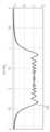
도 5는 표적지연 신호만이 레이더에 수신되는 경우 정합필터를 거친 후 출력되는 출력신호의 일예를 나타낸다.
도 6은 표적지연 신호에 첩잡음이 추가되어 레이더에 수신되는 경우 정합필터를 거친 후 출력되는 출력신호의 일예를 나타낸다.1 is a block diagram showing an apparatus for generating chirp noise corresponding to a compressed pulse signal according to an embodiment of the present invention.
2 is a flowchart illustrating a method for generating chirp noise corresponding to a compressed pulse signal according to an embodiment of the present invention.
3 shows an example of a received signal that has passed through a matched filter of a radar.
4 shows an example of an output signal output after passing through a matched filter of a radar.
5 shows an example of an output signal output after passing through a matched filter when only a target delay signal is received by the radar.
6 shows an example of an output signal output after passing through a matched filter when chirp noise is added to a target delay signal and received by a radar.
이하, 첨부한 도면을 참고로 하여 본 발명의 실시예들에 대하여 본 발명이 속하는 기술 분야에서 통상의 지식을 가진 자가 용이하게 실시할 수 있도록 상세히 설명한다. 본 발명은 여러 가지 상이한 형태로 구현될 수 있으며 여기에서 설명하는 실시예들에 한정되지 않는다.Hereinafter, with reference to the accompanying drawings, embodiments of the present invention will be described in detail so that those skilled in the art can easily carry out the present invention. This invention may be embodied in many different forms and is not limited to the embodiments set forth herein.
본 발명을 명확하게 설명하기 위해서 설명과 관계없는 부분은 생략하였으며, 명세서 전체를 통하여 동일 또는 유사한 구성요소에 대해서는 동일한 참조 부호를 붙이도록 한다.In order to clearly describe the present invention, parts irrelevant to the description are omitted, and the same reference numerals are assigned to the same or similar components throughout the specification.
또한, 명세서 전체에서, 어떤 부분이 어떤 구성요소를 "포함" 한다고 할 때, 이는 특별히 반대되는 기재가 없는 한 다른 구성요소를 제외하는 것이 아니라 다른 구성요소를 더 포함할 수 있는 것을 의미한다.In addition, throughout the specification, when a certain component is said to "include", it means that it may further include other components without excluding other components unless otherwise stated.
이하, 도 1 내지 도 6을 참조하여 본 발명의 실시예에 따른 압축펄스신호에 대응한 첩잡음 발생 장치 및 방법에 대하여 설명한다.Hereinafter, an apparatus and method for generating chirp noise corresponding to a compressed pulse signal according to an embodiment of the present invention will be described with reference to FIGS. 1 to 6 .
도 1은 본 발명의 일 실시예에 따른 압축펄스신호에 대응한 첩잡음 발생 장치를 나타내는 블록도이다.1 is a block diagram showing an apparatus for generating chirp noise corresponding to a compressed pulse signal according to an embodiment of the present invention.
압축펄스신호에 대응한 첩잡음 발생 장치(100)는 수신안테나(101), 송신안테나(102), 신호분석부(110) 및 디지털 주파수 저장부(120)를 포함한다.An apparatus for generating chirp noise corresponding to a compressed pulse signal (100) includes a reception antenna (101), a transmission antenna (102), a signal analysis unit (110), and a digital frequency storage unit (120).
레이더(10)에서 송출되는 신호(11)는 수신안테나(101)를 통해 신호분석부(110)에 입력된다. 레이더(10)는 송출되는 신호(11)로써 압축펄스신호를 사용하여 표적을 탐색하고 추적하는 압축펄스 레이더일 수 있다.The
신호분석부(110)는 수신안테나(101)를 통해 입력된 수신신호의 중심주파수, 펄스폭, 펄스주기 및 펄스 내 변조대역폭 등을 분석한다. 신호분석부(110)는 분석된 내용에 따라 디지털 주파수 저장부(120)에 필요한 정보를 송수신한다. 신호분석부(110)의 분석에 기반하여 전자공격 수행이 필요한 경우 수신안테나(101)로부터 동일한 수신신호가 디지털 주파수 저장부(120)에 입력된다. 즉, 수신안테나(101)를 통해 수신되는 수신신호는 신호분석부(110)와 디지털 주파수 저장부(120)에 동시에 수신되고, 신호분석부(110)는 수신안테나(101)를 통해 입력된 수신신호를 분석하여 전자공격 수행 여부를 판단하여 전자공격 수행이 필요하다고 판단하면 디지털 주파수 저장부(120)에 제어명령을 전송한다. 디지털 주파수 저장부(120)는 신호분석부(110)로부터 전자공격 수행이 필요하다는 제어명령이 수신되면 수신안테나(101)를 통해 입력된 수신신호를 저장한다. 디지털 주파수 저장부(120)에 저장된 수신신호는 잡음이나 기만을 위한 신호로 사용될 수 있다. 즉, 디지털 주파수 저장부(120)는 수신신호를 이용하여 첩잡음을 생성하고, 수신신호와 첩잡음을 합성하여 재밍신호(12)를 생성하고, 송신안테나(102)를 통해 재밍신호(12)를 송신할 수 있다.The
레이더(10)의 압축펄스의 수신신호를 이용하여 첩잡음을 생성하고 수신신호와 첩잡음을 합성하여 재밍신호(12)를 생성하는 방법에 대하여 도 1과 함께 도 2 내지 6을 참조하여 더욱 상세하게 설명한다.A method of generating chirp noise using the received signal of the compressed pulse of the
도 2는 본 발명의 일 실시예에 따른 압축펄스신호에 대응한 첩잡음 발생 방법을 나타내는 흐름도이다. 도 3은 레이더의 정합필터를 통과한 수신신호의 일예를 나타낸다. 도 4는 레이더의 정합필터를 거친 후 출력되는 출력신호의 일예를 나타낸다. 도 5는 표적지연 신호만이 레이더에 수신되는 경우 정합필터를 거친 후 출력되는 출력신호의 일예를 나타낸다. 도 6은 표적지연 신호에 첩잡음이 추가되어 레이더에 수신되는 경우 정합필터를 거친 후 출력되는 출력신호의 일예를 나타낸다.2 is a flowchart illustrating a method for generating chirp noise corresponding to a compressed pulse signal according to an embodiment of the present invention. 3 shows an example of a received signal that has passed through a matched filter of a radar. 4 shows an example of an output signal output after passing through a matched filter of a radar. 5 shows an example of an output signal output after passing through a matched filter when only a target delay signal is received by the radar. 6 illustrates an example of an output signal output after passing through a matched filter when chirp noise is added to a target delay signal and received by a radar.
도 2 내지 6을 참조하면, 신호분석부(110)는 압축펄스 수신신호의 중심주파수, 펄스폭, 펄스주기 및 변조대역폭을 분석하고, 분석된 내용에 따라 디지털 주파수 저장부(120)에 필요한 정보를 송신한다. 즉, 신호분석부(110)는 수신신호의 펄스폭과 변조대역폭을 첩잡음의 펄스폭 및 첩잡음변조대역폭으로써 디지털 주파수 저장부(120)에 송신할 수 있다. 디지털 주파수 저장부(120)는 신호분석부(110)로부터 첩잡음의 펄스폭 및 첩잡음변조대역폭을 수신할 수 있다(S110).2 to 6, the
일반적으로 압축펄스 수신신호는 수학식 1과 같이 나타낼 수 있다.In general, the compressed pulse received signal can be expressed as

여기서, s(t)는 압축펄스 수신신호, f0은 수신신호의 중심주파수, ti는 시간 지연,
표적에 반산된 신호는 레이더(10)의 수신기로 입력되고, 레이더(10)에 수신된 신호는 레이더(10)에 포함된 정합필터(Matched Filter)를 통과한 후 수학식 2와 같이 출력된다. 정합필터는 원하는 신호 성분에 부가적 잡음이 중첩된 입력에 대하여 출력의 어느 시점에서 신호 성분의 제곱 평균값과 잡음 성분의 제곱 평균값과의 비가 최대로 되는 선형 필터이다.The signal reflected by the target is input to the receiver of the

여기서, Sout(t)는 정합필터를 통과한 후 출력되는 신호, fc는 캐리어 주파수를 나타낸다. 정합필터에

수학식 2에 따라 정합필터를 거친 수신신호(200)는 도 3과 같이 나타난다. 펄스폭이 3[usec]이고, 지연시간이 10[usec]일 때 정합필터를 거친 후 출력되는 출력신호(210)는 도 4와 같이 sinc 신호 형태로 출력된다.The received
한편, 첩잡음 발생 장치(100)의 디지털 주파수 저장부(120)에서 수신되는 압축펄스 수신신호는 수학식 3과 같이 나타낼 수 있다.Meanwhile, the compressed pulse reception signal received in the digital

여기서, s(t)는 압축펄스 수신신호, fd는 디지털 주파수 저장부(120)의 중심주파수이다.Here, s(t) is the compressed pulse reception signal, and fd is the center frequency of the digital
디지털 주파수 저장부(120)는 신호분석부(110)에서 분석한 펄스폭(Ts)과 변조대역폭(Bs)과 동일한 펄스폭과 첩잡음변조대역폭을 신호분석부(110)로부터 수신한다. 즉, 신호분석부(110)는 압축펄스 수신신호의 펄스폭과 동일한 펄스폭, 압축펄스 수신신호의 변조대역폭과 동일한 첩잡음변조대역폭을 디지털 주파수 저장부(120)로 송신한다.The digital
디지털 주파수 저장부(120)는 신호분석부(110)로부터 수신한 펄스폭과 첩잡음변조대역폭을 기반으로 첩잡음을 생성한다(S120). 디지털 주파수 저장부(120)는 수학식 4와 같이 첩잡음을 생성할 수 있다.The digital

여기서, R(t)는 첩잡음,

디지털 주파수 저장부(120)는 수신신호와 첩잡음을 합성하여 송신한다(S130). 디지털 주파수 저장부(120)는 위상샘플링을 수행할 수 있으며, 위상샘플링으로 수신신호의 크기와 무관한 위상값을 검출하여 저장할 수 있다. 위상값은 수학식 5와 같이 동위상(inphase phase)과 직교위상(quadrature phase)에 대한 atan 함수로 나타낼 수 있다.The digital

여기서, θs는 위상값, I는 동위상의 크기, Q는 직교위상의 크기를 나타낸다.Here, θs is the phase value, I is the size of the in-phase, and Q is the size of the quadrature.
디지털 주파수 저장부(120)는 수신신호의 위상과 첩잡음의 위상을 합해서 수학식 6과 같이 재밍신호(12)를 생성할 수 있다.The digital

여기서, θs는 수신신호(레이더(10)의 송출 신호(11))의 위상, θr은 디지털 주파수 저장부(120)에서 생성한 첩잡음의 위상, θj는 디지털 주파수 저장부(120)에서 송신되는 재밍신호(12)의 위상을 나타낸다. 즉, 디지털 주파수 저장부(120)는 레이더(10)의 송출 신호(11)의 위상과 첩잡음의 위상을 합하여 재밍신호(12)를 생성할 수 있다.Here, θs is the phase of the received signal (
디지털 주파수 저장부(120)는 수학식 7과 같이 시간도메인에서 압축펄스 수신신호와 첩잡음을 곱하여 재밍신호를 생성할 수 있다.The digital

여기서, J(t)는 재밍신호, B는 첩잡음의 신호 크기를 나타낸다. 수학식 6에 의한 위상합성으로 재밍신호를 생성하는 경우에 B는 1이 된다. 수학식 7과 같이 생성된 재밍신호를 송신하기 위해서는 디지털 주파수 저장부(120) 내부 또는 외부에 위치한 증폭기에서 증폭하여 송신하므로, 최종적으로 송신되는 재밍신호(12)는 수학식 8과 같이 나타낼 수 있다.Here, J(t) represents the jamming signal and B represents the signal level of chirp noise. When a jamming signal is generated by phase synthesis according to

여기서, A는 증폭기의 증폭률이다. 위상합성에 의한 경우 B는 1이 된다. 즉, 디지털 주파수 저장부(120)는 시간도메인에서 압축펄스 수신신호와 첩잡음을 곱하여 생성된 재밍신호를 증폭기의 증폭률만큼 증폭하여 최종적인 재밍신호(12)로서 송신할 수 있다.Here, A is the amplification factor of the amplifier. In the case of phase synthesis, B becomes 1. That is, the digital
디지털 주파수 저장부(120)에서 수신한 레이더(10)의 압축펄스 수신신호의 주파수대역폭은 Bs이고, 디지털 주파수 저장부(120)는 재밍신호(12) 송신시에 첩잡음을 추가하여 송신하므로 주파수대역폭 Bs+Bj의 재밍신호(12)가 송신된다. 즉, 재밍신호(12)의 주파수대역폭은 수신신호의 주파수대역폭과 첩잡음의 첩잡음변조대역폭의 합과 동일할 수 있다.The frequency bandwidth of the compressed pulse reception signal of the
첩잡음이 추가된 재밍신호(12)는 레이더(10)의 정합필터를 거쳐 출력된다. 수학식 2와 동일한 방식으로, 첩잡음이 추가된 재밍신호(12)는 레이더(10)의 정합필터를 거쳐 수학식 9와 같이 출력될 수 있다.The jamming

여기서,
수학식 9가 적용된 압축펄스의 신호가 지연시간 1[usec], 펄스폭 3[usec], 펄스 내 변조대역폭 20[MHz]인 경우, 표적지연 신호만이 레이더(10)에 수신되어 정합필터를 거친 후 출력되는 출력신호는 도 5와 같이 시간지연 1[usec]에 sinc 신호(300)로 출력된다.When the signal of the compressed pulse to which Equation 9 is applied has a delay time of 1 [usec], a pulse width of 3 [usec], and an intra-pulse modulation bandwidth of 20 [MHz], only the target delay signal is received by the
반면, 표적지연 신호에 첩잡음 대역폭 20[MHz]의 첩잡음이 추가된 경우, 도 6과 같이 레이더(10)의 정합필터를 거친 후 출력되는 출력신호는 sinc 신호가 아닌 잡음신호로 출력된다. 즉, 본 발명의 실시예에 따른 압축펄스신호에 대응한 첩잡음 발생 장치 및 방법은 수신신호를 이용하여 생선된 첩잡음을 수신신호와 합성하여 송신함으로써 레이더(10)의 표적 탐지 및 추적을 효과적으로 방해할 수 있다.On the other hand, when chirp noise with a chirp noise bandwidth of 20 [MHz] is added to the target delay signal, the output signal output after passing through the matched filter of the
지금까지 참조한 도면과 기재된 발명의 상세한 설명은 단지 본 발명의 예시적인 것으로서, 이는 단지 본 발명을 설명하기 위한 목적에서 사용된 것이지 의미 한정이나 특허청구범위에 기재된 본 발명의 범위를 제한하기 위하여 사용된 것은 아니다. 그러므로 본 기술 분야의 통상의 지식을 가진 자라면 이로부터 다양한 변형 및 균등한 타 실시 예가 가능하다는 점을 이해할 것이다. 따라서, 본 발명의 진정한 기술적 보호 범위는 첨부된 특허청구범위의 기술적 사상에 의해 정해져야 할 것이다.The drawings and detailed description of the present invention referred to so far are only examples of the present invention, which are only used for the purpose of explaining the present invention, and are used to limit the scope of the present invention described in the meaning or claims. It is not. Therefore, those skilled in the art will understand that various modifications and equivalent other embodiments are possible therefrom. Therefore, the true technical protection scope of the present invention should be determined by the technical spirit of the appended claims.
10: 레이더 100: 첩잡음 발생 장치
101: 수신안테나 102: 송신안테나
110: 신호분석부 120: 디지털 주파수 저장부10: radar 100: spy noise generator
101: receiving antenna 102: transmitting antenna
110: signal analysis unit 120: digital frequency storage unit
Claims (13)
Translated fromKorean상기 수신안테나를 통해 입력된 수신신호를 분석하여 전자공격 수행 여부를 판단하는 신호분석부; 및
상기 신호분석부로부터 상기 전자공격 수행이 필요하다는 제어명령이 수신되면 상기 수신안테나를 통해 입력된 수신신호를 저장하고, 상기 수신신호를 이용하여 첩잡음을 생성하고, 상기 수신신호와 상기 첩잡음을 합성하여 재밍신호를 생성하고, 상기 재밍신호를 송신하는 디지털 주파수 저장부를 포함하고,
상기 디지털 주파수 저장부는 위상샘플링으로 상기 수신신호의 크기와 무관한 위상을 검출하고, 상기 위상샘플링으로 검출한 상기 수신신호의 위상과 상기 첩잡음의 위상을 합해서 상기 재밍신호를 생성하는 압축펄스신호에 대응한 첩잡음 발생 장치.receiving antenna;
a signal analysis unit that analyzes the received signal input through the reception antenna to determine whether an electronic attack is performed; and
When a control command indicating that the electronic attack needs to be performed is received from the signal analyzer, the reception signal input through the reception antenna is stored, and spy noise is generated using the received signal, and the received signal and the spy noise are stored. A digital frequency storage unit for synthesizing and generating a jamming signal and transmitting the jamming signal;
The digital frequency storage unit detects a phase independent of the magnitude of the received signal through phase sampling, and adds the phase of the received signal detected through the phase sampling and the phase of the chirp noise to a compressed pulse signal for generating the jamming signal. Corresponding secret noise generator.
상기 신호분석부는 상기 수신신호를 분석하여 상기 디지털 주파수 저장부에 펄스폭 및 첩잡음변조대역폭을 송신하는 압축펄스신호에 대응한 첩잡음 발생 장치.According to claim 1,
The signal analysis unit analyzes the received signal and transmits a pulse width and a chirp noise modulation bandwidth to the digital frequency storage unit.
상기 디지털 주파수 저장부는 상기 신호분석부로부터 수신한 상기 펄스폭과 상기 첩잡음변조대역폭을 기반으로 상기 첩잡음을 생성하는 압축펄스신호에 대응한 첩잡음 발생 장치.According to claim 2,
wherein the digital frequency storage unit generates the chirp noise based on the pulse width received from the signal analysis unit and the chirp noise modulation bandwidth.
상기 수신신호의 위상은 수학식

상기 θs는 상기 수신신호의 위상, 상기 I는 동위상의 크기, Q는 직교위상의 크기인 압축펄스신호에 대응한 첩잡음 발생 장치.According to claim 1,
The phase of the received signal is expressed by Equation
wherein θs is the phase of the received signal, I is the magnitude of the same phase, and Q is the magnitude of the quadrature phase.
상기 수신안테나를 통해 입력된 수신신호를 분석하여 전자공격 수행 여부를 판단하는 신호분석부; 및
상기 신호분석부로부터 상기 전자공격 수행이 필요하다는 제어명령이 수신되면 상기 수신안테나를 통해 입력된 수신신호를 저장하고, 상기 수신신호를 이용하여 첩잡음을 생성하고, 상기 수신신호와 상기 첩잡음을 합성하여 재밍신호를 생성하고, 상기 재밍신호를 송신하는 디지털 주파수 저장부를 포함하고,
상기 디지털 주파수 저장부는 시간도메인에서 상기 수신신호와 상기 첩잡음을 곱하여 상기 재밍신호를 생성하는 압축펄스신호에 대응한 첩잡음 발생 장치.receiving antenna;
a signal analysis unit that analyzes the received signal input through the reception antenna to determine whether an electronic attack is performed; and
When a control command indicating that the electronic attack needs to be performed is received from the signal analyzer, the reception signal input through the reception antenna is stored, and spy noise is generated using the received signal, and the received signal and the spy noise are stored. A digital frequency storage unit for synthesizing and generating a jamming signal and transmitting the jamming signal;
wherein the digital frequency storage unit generates the jamming signal by multiplying the received signal and the chirp noise in the time domain.
상기 재밍신호의 주파수대역폭은 상기 수신신호의 주파수대역폭과 상기 첩잡음변조대역폭의 합과 동일한 압축펄스신호에 대응한 첩잡음 발생 장치.According to claim 3,
The chirp noise generator corresponding to the compressed pulse signal wherein the frequency bandwidth of the jamming signal is equal to the sum of the frequency bandwidth of the received signal and the chirp noise modulation bandwidth.
상기 펄스폭과 상기 첩잡음변조대역폭을 기반으로 첩잡음을 생성하는 단계; 및
위상샘플링으로 상기 수신신호의 크기와 무관한 위상을 검출하고, 상기 위상샘플링으로 검출한 상기 수신신호의 위상과 상기 첩잡음의 위상을 합해서 재밍신호를 생성하고, 상기 재밍신호를 송신하는 단계를 포함하는 압축펄스신호에 대응한 첩잡음 발생 방법.receiving a pulse width of a spooky noise and a spooky noise modulation bandwidth according to analysis of a received signal input through a reception antenna;
generating chirp noise based on the pulse width and the chirp noise modulation bandwidth; and
Detecting a phase independent of the magnitude of the received signal through phase sampling, generating a jamming signal by adding the phase of the received signal detected through the phase sampling and the phase of the chirp noise, and transmitting the jamming signal. A method for generating chirp noise in response to a compressed pulse signal
상기 수신신호를 분석하여 전자공격 수행 여부를 판단하는 단계; 및
상기 전자공격 수행이 필요하다는 제어명령에 따라 상기 수신신호를 저장하는 단계를 더 포함하는 압축펄스신호에 대응한 첩잡음 발생 방법.According to claim 8,
analyzing the received signal to determine whether an electronic attack is performed; and
and storing the received signal according to a control command indicating that the electronic attack needs to be performed.
상기 수신신호의 위상은 수학식

상기 θs는 상기 수신신호의 위상, 상기 I는 동위상의 크기, Q는 직교위상의 크기인 압축펄스신호에 대응한 첩잡음 발생 방법.According to claim 8,
The phase of the received signal is expressed by Equation
wherein θs is the phase of the received signal, I is the magnitude of the same phase, and Q is the magnitude of the quadrature phase.
상기 펄스폭과 상기 첩잡음변조대역폭을 기반으로 첩잡음을 생성하는 단계; 및
시간도메인에서 상기 수신신호와 상기 첩잡음을 곱하여 재밍신호를 생성하고, 상기 재밍신호를 송신하는 단계를 포함하는 압축펄스신호에 대응한 첩잡음 발생 방법.receiving a pulse width of a spooky noise and a spooky noise modulation bandwidth according to analysis of a received signal input through a reception antenna;
generating chirp noise based on the pulse width and the chirp noise modulation bandwidth; and
and generating a jamming signal by multiplying the received signal by the chirp noise in the time domain, and transmitting the jamming signal.
상기 재밍신호의 주파수대역폭은 상기 수신신호의 주파수대역폭과 상기 첩잡음변조대역폭의 합과 동일한 압축펄스신호에 대응한 첩잡음 발생 방법.According to claim 8,
The method of generating chirp noise corresponding to a compressed pulse signal in which the frequency bandwidth of the jamming signal is equal to the sum of the frequency bandwidth of the received signal and the chirp noise modulation bandwidth.
Priority Applications (2)
| Application Number | Priority Date | Filing Date | Title |
|---|---|---|---|
| KR1020210042987AKR102499402B1 (en) | 2021-04-01 | 2021-04-01 | Chirp noise generation device and method for compression pulse signal |
| US17/322,434US11411670B1 (en) | 2021-04-01 | 2021-05-17 | Chirp noise generation device and method for compression pulse signal |
Applications Claiming Priority (1)
| Application Number | Priority Date | Filing Date | Title |
|---|---|---|---|
| KR1020210042987AKR102499402B1 (en) | 2021-04-01 | 2021-04-01 | Chirp noise generation device and method for compression pulse signal |
Publications (2)
| Publication Number | Publication Date |
|---|---|
| KR20220136826A KR20220136826A (en) | 2022-10-11 |
| KR102499402B1true KR102499402B1 (en) | 2023-02-10 |
Family
ID=82705869
Family Applications (1)
| Application Number | Title | Priority Date | Filing Date |
|---|---|---|---|
| KR1020210042987AActiveKR102499402B1 (en) | 2021-04-01 | 2021-04-01 | Chirp noise generation device and method for compression pulse signal |
Country Status (2)
| Country | Link |
|---|---|
| US (1) | US11411670B1 (en) |
| KR (1) | KR102499402B1 (en) |
Citations (1)
| Publication number | Priority date | Publication date | Assignee | Title |
|---|---|---|---|---|
| KR102012386B1 (en)* | 2018-04-16 | 2019-08-20 | 국방과학연구소 | Apparatus for generating a deception signal for a pulse compression signal and method therefor |
Family Cites Families (6)
| Publication number | Priority date | Publication date | Assignee | Title |
|---|---|---|---|---|
| US4743905A (en)* | 1985-08-16 | 1988-05-10 | Westinghouse Electric Corp. | Electronic counter measure system utilizing a digital RF memory |
| JP2002328160A (en) | 2001-04-27 | 2002-11-15 | Mitsubishi Electric Corp | Digital RF memory |
| US6618007B1 (en)* | 2002-06-04 | 2003-09-09 | Raytheon Company | Adaptive weight calculation preprocessor |
| US10222454B2 (en) | 2014-08-19 | 2019-03-05 | Navico Holding As | Combining Reflected Signals |
| KR102100851B1 (en)* | 2018-07-30 | 2020-04-14 | 엘아이지넥스원 주식회사 | Jamming signal generating apparatus and method thereof |
| KR102149456B1 (en) | 2019-05-21 | 2020-08-31 | 국방과학연구소 | Method and apparatus for simultaneously performing jamming function and communication function |
- 2021
- 2021-04-01KRKR1020210042987Apatent/KR102499402B1/enactiveActive
- 2021-05-17USUS17/322,434patent/US11411670B1/enactiveActive
Patent Citations (1)
| Publication number | Priority date | Publication date | Assignee | Title |
|---|---|---|---|---|
| KR102012386B1 (en)* | 2018-04-16 | 2019-08-20 | 국방과학연구소 | Apparatus for generating a deception signal for a pulse compression signal and method therefor |
Also Published As
| Publication number | Publication date |
|---|---|
| KR20220136826A (en) | 2022-10-11 |
| US11411670B1 (en) | 2022-08-09 |
Similar Documents
| Publication | Publication Date | Title |
|---|---|---|
| Sun et al. | Moving variance-based signal quality monitoring method for spoofing detection | |
| CA2255890C (en) | Virtual noise radar waveform for reduced radar detectability | |
| US7676205B2 (en) | Active receiver detection and ranging | |
| KR102012386B1 (en) | Apparatus for generating a deception signal for a pulse compression signal and method therefor | |
| US7250900B2 (en) | System and method for sidelobe reduction using detect-and-subtract techniques | |
| JP2007248215A (en) | Radar equipment | |
| Hanbali | A review of radar signals in terms of Doppler tolerance, time-sidelobe level, and immunity against jamming | |
| US5047780A (en) | Pulse radar apparatus and pulse discrimination circuit suitable for incorporation in a pulse radar apparatus | |
| Xu et al. | Repeat radar jammer suppression for a colocated MIMO radar | |
| Blum et al. | New and existing signal quality monitoring metrics tested against simulations and time synchronized signal generator attacks | |
| Hanbali et al. | A review of self-protection deceptive jamming against chirp radars | |
| CN110109075A (en) | Frequency-agile radar anti-interference method based on whitening filtering | |
| KR102499402B1 (en) | Chirp noise generation device and method for compression pulse signal | |
| JP4762739B2 (en) | Transceiver | |
| US7248207B2 (en) | System and method for sidelobe reduction using point spread function expansion | |
| KR101052034B1 (en) | Multifunction receiver of electronic warfare system | |
| US5109231A (en) | Radar arrangement | |
| JP2013190217A (en) | Radar interference removal apparatus and radar interference removal method | |
| CN106054142A (en) | Airborne multi-input-multi-output radar main lobe smart interference inhibition method and system | |
| KR100851888B1 (en) | Radar for eliminating clutter and transmission leakage power | |
| Vu et al. | A comparative overview of automotive radar spoofing countermeasures | |
| JP2008241319A (en) | Pulse radar equipment | |
| JP2000121723A (en) | Radar jammer | |
| Shahrab et al. | Secure hybrid pulse compression as a technique against jamming in radar systems | |
| JPH09270772A (en) | Interfering device |
Legal Events
| Date | Code | Title | Description |
|---|---|---|---|
| PA0109 | Patent application | Patent event code:PA01091R01D Comment text:Patent Application Patent event date:20210401 | |
| PA0201 | Request for examination | ||
| PE0902 | Notice of grounds for rejection | Comment text:Notification of reason for refusal Patent event date:20220804 Patent event code:PE09021S01D | |
| PG1501 | Laying open of application | ||
| E90F | Notification of reason for final refusal | ||
| PE0902 | Notice of grounds for rejection | Comment text:Final Notice of Reason for Refusal Patent event date:20221124 Patent event code:PE09021S02D | |
| E701 | Decision to grant or registration of patent right | ||
| PE0701 | Decision of registration | Patent event code:PE07011S01D Comment text:Decision to Grant Registration Patent event date:20230126 | |
| GRNT | Written decision to grant | ||
| PR0701 | Registration of establishment | Comment text:Registration of Establishment Patent event date:20230208 Patent event code:PR07011E01D | |
| PR1002 | Payment of registration fee | Payment date:20230208 End annual number:3 Start annual number:1 | |
| PG1601 | Publication of registration |