KR102498649B1 - Diagnosis of pressure pulses on on-load tap-changers - Google Patents
Diagnosis of pressure pulses on on-load tap-changersDownload PDFInfo
- Publication number
- KR102498649B1 KR102498649B1KR1020217038923AKR20217038923AKR102498649B1KR 102498649 B1KR102498649 B1KR 102498649B1KR 1020217038923 AKR1020217038923 AKR 1020217038923AKR 20217038923 AKR20217038923 AKR 20217038923AKR 102498649 B1KR102498649 B1KR 102498649B1
- Authority
- KR
- South Korea
- Prior art keywords
- pressure
- vacuum
- housing
- tap changer
- signature
- Prior art date
- Legal status (The legal status is an assumption and is not a legal conclusion. Google has not performed a legal analysis and makes no representation as to the accuracy of the status listed.)
- Active
Links
- 238000003745diagnosisMethods0.000title1
- 239000012530fluidSubstances0.000claimsabstractdescription41
- 238000000034methodMethods0.000claimsabstractdescription33
- 238000012544monitoring processMethods0.000claimsabstractdescription33
- 238000012545processingMethods0.000claimsabstractdescription28
- 230000003068static effectEffects0.000claimsdescription18
- 230000003213activating effectEffects0.000claimsdescription8
- 238000004519manufacturing processMethods0.000claimsdescription3
- 239000007789gasSubstances0.000description18
- 238000004891communicationMethods0.000description7
- 238000004804windingMethods0.000description7
- 230000009471actionEffects0.000description6
- 230000008859changeEffects0.000description4
- 238000010079rubber tappingMethods0.000description4
- 230000007423decreaseEffects0.000description3
- 238000013461designMethods0.000description3
- 238000004880explosionMethods0.000description3
- UFHFLCQGNIYNRP-UHFFFAOYSA-NHydrogenChemical compound[H][H]UFHFLCQGNIYNRP-UHFFFAOYSA-N0.000description2
- 230000033228biological regulationEffects0.000description2
- 238000009826distributionMethods0.000description2
- 239000007788liquidSubstances0.000description2
- 230000008569processEffects0.000description2
- 230000008439repair processEffects0.000description2
- 239000004215Carbon black (E152)Substances0.000description1
- 230000005540biological transmissionEffects0.000description1
- 239000003990capacitorSubstances0.000description1
- 239000002826coolantSubstances0.000description1
- 238000010586diagramMethods0.000description1
- 238000010891electric arcMethods0.000description1
- 229930195733hydrocarbonNatural products0.000description1
- 150000002430hydrocarbonsChemical class0.000description1
- 239000001257hydrogenSubstances0.000description1
- 229910052739hydrogenInorganic materials0.000description1
- 238000009413insulationMethods0.000description1
- 230000007257malfunctionEffects0.000description1
- 239000000615nonconductorSubstances0.000description1
- 238000013021overheatingMethods0.000description1
- 238000010791quenchingMethods0.000description1
- 238000012546transferMethods0.000description1
- 230000007704transitionEffects0.000description1
- 230000000007visual effectEffects0.000description1
Images


Classifications
- H—ELECTRICITY
- H01—ELECTRIC ELEMENTS
- H01H—ELECTRIC SWITCHES; RELAYS; SELECTORS; EMERGENCY PROTECTIVE DEVICES
- H01H9/00—Details of switching devices, not covered by groups H01H1/00 - H01H7/00
- H01H9/0005—Tap change devices
- G—PHYSICS
- G01—MEASURING; TESTING
- G01R—MEASURING ELECTRIC VARIABLES; MEASURING MAGNETIC VARIABLES
- G01R31/00—Arrangements for testing electric properties; Arrangements for locating electric faults; Arrangements for electrical testing characterised by what is being tested not provided for elsewhere
- G01R31/327—Testing of circuit interrupters, switches or circuit-breakers
- G01R31/333—Testing of the switching capacity of high-voltage circuit-breakers ; Testing of breaking capacity or related variables, e.g. post arc current or transient recovery voltage
- H—ELECTRICITY
- H01—ELECTRIC ELEMENTS
- H01H—ELECTRIC SWITCHES; RELAYS; SELECTORS; EMERGENCY PROTECTIVE DEVICES
- H01H9/00—Details of switching devices, not covered by groups H01H1/00 - H01H7/00
- H01H9/0005—Tap change devices
- H01H9/0038—Tap change devices making use of vacuum switches
- H—ELECTRICITY
- H01—ELECTRIC ELEMENTS
- H01H—ELECTRIC SWITCHES; RELAYS; SELECTORS; EMERGENCY PROTECTIVE DEVICES
- H01H9/00—Details of switching devices, not covered by groups H01H1/00 - H01H7/00
- H01H9/0005—Tap change devices
- H01H2009/0061—Monitoring tap change switching devices
- H—ELECTRICITY
- H01—ELECTRIC ELEMENTS
- H01H—ELECTRIC SWITCHES; RELAYS; SELECTORS; EMERGENCY PROTECTIVE DEVICES
- H01H33/00—High-tension or heavy-current switches with arc-extinguishing or arc-preventing means
- H01H33/60—Switches wherein the means for extinguishing or preventing the arc do not include separate means for obtaining or increasing flow of arc-extinguishing fluid
- H01H33/66—Vacuum switches
- H01H33/668—Means for obtaining or monitoring the vacuum
Landscapes
- Physics & Mathematics (AREA)
- General Physics & Mathematics (AREA)
- Measuring Fluid Pressure (AREA)
- High-Tension Arc-Extinguishing Switches Without Spraying Means (AREA)
Abstract
Translated fromKoreanDescription
Translated fromKorean본 발명은 진공 부하시 탭 전환기 (on-load tap changer) 를 모니터링하기 위한 방법 및 모니터링 시스템에 관한 것이다.The present invention relates to a method and monitoring system for monitoring a vacuum on-load tap changer.
탭 전환기는 전압 레벨들의 조절을 위해 변압기와 함께 사용되는 디바이스이다. 그 조절은 변압기의 권선에서의 턴 수를 변경하는 탭 전환기를 가짐으로써 달성된다.A tap changer is a device used in conjunction with a transformer for the regulation of voltage levels. That regulation is achieved by having a tap changer that changes the number of turns in the windings of the transformer.
부하시 탭 전환기들 (OLTC) 은 일반적으로, 하나의 전압 탭으로부터 다음 전압 탭으로의 전류 전달을 실시하기 위한 유닛으로서 동작하는 디버터 스위치 및 탭 선택기 스위치를 포함한다.On-load tap changers (OLTC) generally include a diverter switch and a tap selector switch that operate as a unit for effecting current transfer from one voltage tap to the next.
디버터 스위치는 전류들의 전체 부하시 생성 및 차단을 수행하는 반면, 탭 선택기는 디버터 스위치가 부하 전류를 전달할 탭을 미리 선택한다. 탭 선택기는 오프 로드로 동작한다.The diverter switch performs full-load generation and breaking of currents, while the tap selector preselects the tap to which the diverter switch will deliver the load current. The tap selector works off-load.
변압기로부터 출력된 전력이 하나의 전압 레벨로부터 다른 전압 레벨로 변경되어야 할 때, 그 변경은 디버터 스위치가 기존의 전압 레벨로부터 여전히 피딩하는 동안 새로운 전압 레벨에 대응하는 변압기 권선의 그 탭핑 포인트에 탭 선택기를 먼저 연결함으로써 발생한다. 따라서, 탭 선택기의 연결은 전류 부하 없이 발생한다. 탭 선택기가 새로운 전압 레벨에 대한 탭에 연결될 때, 스위칭 동작이 디버터 스위치의 도움으로 발생하여 출력 전류가 변압기의 새로운 탭핑 포인트로부터 취해진다. 변압기가 복수의 탭핑 포인트들을 갖는 경우, 스위칭은 통상적으로, 전압의 관점에서 서로 가까운 2개의 탭핑 포인트들 사이에서만 발생한다. 더 먼 위치에 대한 조정이 요구되어야 한다면, 이는 단계별로 발생한다.When the power output from the transformer must change from one voltage level to another, the change taps to that tapping point of the transformer winding corresponding to the new voltage level while the diverter switch is still feeding from the old voltage level. This happens by connecting the selector first. Thus, the connection of the tap selector takes place without a current load. When the tap selector is connected to the tap for the new voltage level, a switching action takes place with the help of the diverter switch so that the output current is taken from the new tapping point of the transformer. When a transformer has multiple tapping points, switching typically only occurs between two tapping points that are close to each other in terms of voltage. If adjustments to more distant locations are to be required, this occurs in stages.
여기서 지칭되는 종류의 디버터 스위치는 통상적으로, 전력의 제어를 위해 또는 배전 변압기들을 위해 사용된다. OLTC 는 또한, 반응기들, 산업용 변압기들, 위상 시프터들, 커패시터들 등과 같은 전력 전송 또는 분배 제품들과 같은 다른 타입들의 전기 디바이스들의 제어를 위해 유리하게 사용될 수도 있다.A diverter switch of the type referred to herein is typically used for control of electrical power or for distribution transformers. OLTC may also be advantageously used for control of other types of electrical devices such as power transmission or distribution products such as reactors, industrial transformers, phase shifters, capacitors, and the like.
디버터 스위치의 동작은 전기 아크의 뒤따르는 발생과 함께 하나의 회로로부터 다른 회로로의 전환을 수반한다. 디버터 스위치는, 모든 서브시스템들과 함께, 하우징에 배치되고 오일과 같은 절연 유체에 침지된다. OLTC 는 절연 유체, 디버터 스위치들 및 서브시스템들과 함께 하우징을 포함한다.Operation of the diverter switch involves switching from one circuit to another with the subsequent generation of an electric arc. The diverter switch, together with all subsystems, is placed in a housing and immersed in an insulating fluid such as oil. The OLTC includes a housing with insulating fluid, diverter switches and subsystems.
탱크에서의 절연 유체는 전기 절연체로서 및 냉각제로서 작용하여 OLTC 에서의 발생된 열을 제거한다. 절연 유체는 또한, 스위칭 동안 발생된 아크들을 ??칭할 것이다. OLTC 의 동작 동안 아킹은 절연 유체를 오염시키고 스위치 컨택들을 마모시킬 것이다.The insulating fluid in the tank acts as an electrical insulator and coolant to remove the heat generated in the OLTC. The insulating fluid will also quench the arcs generated during switching. Arcing during operation of the OLTC will contaminate the insulating fluid and wear out the switch contacts.
절연 유체에서의 아킹을 극복하기 위해, 아크가 발생하는 그러한 스위칭 동작들을 위해 진공 스위치들 또는, 다시 말해서, 진공 인터럽터들을 사용하는 것이 이미 공지되어 있다. 그 다음, 전기 컨택 마모 및 아크들은 진공 인터럽터에서만 발생할 것이다. 전기적 관점으로부터의 적절한 절차를 위해, 이러한 종류의 디버터 스위치에는 적어도 하나의 메인 브랜치 및 하나의 저항 브랜치가 제공되고, 각각의 브랜치는 진공 인터럽터를 갖는다.To overcome arcing in an insulating fluid, it is already known to use vacuum switches or, in other words, vacuum interrupters, for such switching operations in which arcing occurs. Then electrical contact wear and arcs will only occur in the vacuum interrupter. For proper procedure from an electrical point of view, diverter switches of this kind are provided with at least one main branch and one resistive branch, each branch having a vacuum interrupter.
상기 종류의 디버터 스위치는, 예를 들어, US 5,786,552 로부터 이미 공지되어 있다. 여기에서 기술된 디버터 스위치는, 병렬로 연결되고 출력 라인에 연결된 정상 상태에서, 하나의 메인 브랜치 및 하나의 저항 브랜치를 갖는다. 각각의 브랜치에는 진공 인터럽터 및 그와 직렬로 연결된 컨택이 제공된다. 이들은, 디버터 스위칭이 발생할 때 명확한 시퀀스로 동작되며, 이 경우, OLTC 를 위한 저항 브랜치 전에 메인 브랜치가 동작됨을 보장하는 것이 중요하다. 일부 부하 인터럽터들에 대해, 메인 브랜치는 저항 브랜치 전에 동작되지 않는다. 메인 브랜치의 진공 인터럽터는 부하 전류만의 차단을 위해 치수화되고, 저항 브랜치의 진공 인터럽터는, 발생하는 순환 전류에 대해 치수화될 수도 있다. 역 시퀀스의 경우, 메인 브랜치의 진공 인터럽터는 이들 전류들의 합을 차단하도록 강제될 것이고, 따라서, 그에 따라 치수화될 것이다.A diverter switch of this kind is already known, for example from US Pat. No. 5,786,552. The diverter switch described herein has, in steady state, one main branch and one resistive branch connected in parallel and connected to the output line. Each branch is provided with a vacuum interrupter and a contact connected in series therewith. They are operated in a clear sequence when the diverter switching occurs, in which case it is important to ensure that the main branch is operated before the resistor branch for the OLTC. For some load interrupters, the main branch is not actuated before the resistance branch. The vacuum interrupter of the main branch is dimensioned for interruption only of the load current, the vacuum interrupter of the resistance branch may also be dimensioned for the circulating current that arises. In the case of the reverse sequence, the vacuum interrupter of the main branch will be forced to block the sum of these currents and will therefore be dimensioned accordingly.
US 3,206,569 는 진공 인터럽터들이 제공된 탭 전환기를 예시한다. 탭 전환기는 메인 변압기에 연결된다. 탭 전환기는 변압기로부터 분리되고, 변압기와 동일한 컨테이너 및 액체에 또는 별도의 컨테이너 및 별도의 액체에 제공된다. 가스를 수집하기 위해 제공된 후드는 탭 전환기 위에 배열되고, 후드는 가스를 가스 센서에 전달하도록 적응된다. 가스 센서는 수소와 탄화수소 가스들을 감지하는 타입이다. 진공 인터럽터가 고장나면, 컨택터들은 개방되고, 가스 버블을 생성하는 아크를 끌어당긴다. 수소 가스가 센서에 의해 검출되고, 센서는 알람을 준다. 이러한 방식으로, 알람은 진공 인터럽터가 오작동하고 있음을 표시한다.US 3,206,569 illustrates a tap changer provided with vacuum interrupters. The tap changer is connected to the main transformer. The tap changer is separate from the transformer and is provided either in the same container and liquid as the transformer or in a separate container and separate liquid. A hood provided for collecting the gas is arranged above the tap changer and the hood is adapted to deliver the gas to the gas sensor. The gas sensor is a type that detects hydrogen and hydrocarbon gases. If the vacuum interrupter fails, the contactors open and draw an arc creating gas bubbles. Hydrogen gas is detected by the sensor, and the sensor gives an alarm. In this way, an alarm indicates that the vacuum interrupter is malfunctioning.
진공 인터럽터 고장의 경우, OLTC 에서의 보조 컨택 시스템은 OLTC 타입 및 부하에 의존하여, 가능하게는 10 내지 500 회의 제한된 횟수로 전류를 차단 가능하다. 보조 컨택 시스템, 즉, 디버터 스위치의 가동 컨택이 한계 횟수보다 더 많이 전류를 차단해야 하면, 아크들에 의해 야기되는 마모는 컨택들이 더 이상 연결되지 않고 전류를 안내하지 않는 것으로 유도한다. 보조 메인 컨택들이 연결될 수 없으면, 2가지 일들이 발생할 수 있다:In case of vacuum interrupter failure, the auxiliary contact system in the OLTC is capable of breaking the current for a limited number of times, possibly 10 to 500, depending on the OLTC type and load. If the movable contact of the auxiliary contact system, i.e. the diverter switch, has to interrupt current more than a limit number of times, the wear caused by the arcs leads to the contacts no longer being connected and not conducting current. If the auxiliary main contacts cannot connect, two things can happen:
1. 메인 회로가 인터럽트되고, 부하는 저항 회로 상으로 전달된다. 전이 저항기 상의 연속적인 완전 부하로, 저항기는 결국 용융되고, 결과적으로 OLTC 내부에서 성장하는 아크로 파괴될 것이다. 바라건대, 이러한 아크는 검출될 것이고, OLTC-변압기 시스템의 즉각적인 긴급 셧다운을 초래할 것이다. 디버터 스위치의 긴 수리 또는 교환이 결과일 것이고, 수리 시간 동안, 변압기는 오프-라인일 것이다.1. The main circuit is interrupted, and the load is transferred onto the resistor circuit. With a continuous full load on the transition resistor, the resistor will eventually melt and eventually destroy with an arc growing inside the OLTC. Hopefully, this arc will be detected and will result in an immediate emergency shutdown of the OLTC-transformer system. A lengthy repair or replacement of the diverter switch will result, and during repair time, the transformer will be off-line.
2. 스탠딩 아크가 보조 컨택들 위에 나타나고, 이는 2개 위상들 사이의 단락을 야기할 수 있으며 이는 치명적인 고장, 예컨대, 폭발 또는 화재를 야기할 것이다. 운이 좋으면, 스탠딩 아크는 ??칭되고 하나는 포인트 1 로 돌아간다.2. A standing arc appears over the auxiliary contacts, which can cause a short circuit between the two phases which will cause catastrophic failure, eg explosion or fire. With luck, the standing arcs are quenched and one returns to
전술된 바와 같이, OLTC 가 고장날 경우, 폭발 또는 화재의 위험이 있다. 따라서, 그러한 고장을 회피하기 위해 OLTC 의 제어를 개선시킬 필요성이 항상 존재한다.As described above, if the OLTC fails, there is a risk of explosion or fire. Therefore, there is always a need to improve the control of the OLTC to avoid such failures.
본 발명의 목적은 진공 부하시 탭 전환기를 모니터링하기 위한 개선된 방법 및 모니터링 시스템을 제공하는 것이다.It is an object of the present invention to provide an improved method and monitoring system for monitoring vacuum on-load tap changers.
이러한 목적은 청구항 제1항에서 정의된 바와 같은 방법 및 청구항 제7항에서 정의된 바와 같은 모니터링 시스템에 의해 달성된다.This object is achieved by a method as defined in
본 개시는 진공 부하시 탭 전환기를 모니터링하기 위한 방법을 제공한다. 탭 전환기는 절연 유체로 충진된 하우징, 하우징의 내부에 배열되고 적어도 하나의 가동 컨택 (MC, RC) 및 적어도 하나의 가동 컨택을 통해 전류를 인터럽트하기 위한 적어도 2개의 진공 인터럽터들 (MV, RV) 을 포함하는 디버터 스위치, 및 하우징에서의 압력을 측정하는 적어도 하나의 압력 센서를 포함한다. 그 방법은, 미리결정된 시간 인터벌 내에서 2개의 후속 피크들을 포함하는 압력 시그너처를 결정하는 단계로서, 최대 압력은 미리결정된 레벨을 초과하지 않는, 상기 압력 시그너처를 결정하는 단계, 압력 센서로 하우징에서의 압력을 계속적으로 측정하는 단계, 측정된 압력이 압력 시그너처를 나타낼 때를 검출하는 단계, 압력 시그너처 내에서의 측정된 압력에 기초하여, 압력에서의 제 1 상승과 제 2 강하 사이의 시간을 결정하는 단계, 및 결정된 시간을 디버터 스위치의 스위치 시간을 나타내도록 설정하는 단계를 포함한다. 이 방법으로, 스위치 시간이 결정될 수 있다. 스위치 시간을 결정함으로써, 저속 동작이 검출될 수 있다. 저속 동작은 탭 전환기를 과열시킬 수 있고, 심각한 과열 시 고장을 야기할 수 있다. 디버터 스위치의 동작 시간이 결정되어야 하는 것이 CIGRE 공보 "Recommendations for Condition Monitoring and Condition Assessment Facilities for Transformers WG A2.27" from April 2008, under 7.6.3 에서 권장된다. 이 방법은 그 권장에 대한 솔루션을 제공한다.The present disclosure provides a method for monitoring a vacuum on-load tap changer. The tap changer comprises a housing filled with an insulating fluid, at least one movable contact (MC, RC) arranged inside the housing and at least two vacuum interrupters (MV, RV) for interrupting the current through the at least one movable contact. A diverter switch comprising a, and at least one pressure sensor for measuring the pressure in the housing. The method includes determining a pressure signature comprising two subsequent peaks within a predetermined time interval, wherein a maximum pressure does not exceed a predetermined level, determining the pressure signature at the housing with a pressure sensor. continuously measuring pressure, detecting when the measured pressure represents a pressure signature, determining a time between a first rise and a second drop in pressure based on the measured pressure within the pressure signature; and setting the determined time to indicate the switch time of the diverter switch. In this way, the switch time can be determined. By determining the switch time, low-speed operation can be detected. Low-speed operation can overheat the tap changer, which can lead to failure in severe overheating. It is recommended in the CIGRE Bulletin "Recommendations for Condition Monitoring and Condition Assessment Facilities for Transformers WG A2.27" from April 2008, under 7.6.3 that the operating time of the diverter switch be determined. This method provides a solution to that recommendation.
일부 양태들에 따르면, 그 방법은 제 2 피크가 후속 강하를 나타내지 않지만 측정된 압력이 압력 시그너처를 나타낼 때를 검출하는 단계, 및 진공 부하시 탭 전환기가 오작동하고 있음과 안전한 포지션에 도달하였음을 표시하는 알람을 활성화하는 단계를 포함한다. 따라서, 오퍼레이터는, OLTC 가 오작동하고 있지만 제 2 진공 인터럽터가 폐쇄되지 않은 안전한 포지션에 도달하였음을 통지받을 수 있다. 그 다음, 적절한 액션들이 오퍼레이터에 의해 취해질 수 있다.According to some aspects, the method includes detecting when the second peak does not indicate a subsequent drop but the measured pressure indicates a pressure signature, and an indication that the vacuum on-load tap changer is malfunctioning and that a safe position has been reached. and activating an alarm that Thus, the operator can be notified that the OLTC is malfunctioning but has reached a safe position where the second vacuum interrupter is not closed. Appropriate actions can then be taken by the operator.
일부 양태들에 따르면, 그 방법은 측정된 압력이 압력 시그너처를 나타낼 때 및 피크들에서의 압력이 미리결정된 압력 레벨을 초과하지 않을 때를 검출하는 단계, 및 진공 부하시 탭 전환기가 가스 생성 이벤트를 가졌음을 표시하는 알람을 활성화하는 단계를 포함한다. 그 다음, 오퍼레이터는 적절한 액션을 취할 수 있다. 피크들에서의 압력이 미리결정된 수의 동작들에 대해 미리결정된 레벨보다 낮으면, 디버터 스위치에서의 자유 가스가 제거되지 않았기 때문에, OLTC 는 셧다운될 수도 있다.According to some aspects, the method includes detecting when the measured pressure exhibits a pressure signature and when the pressure at the peaks does not exceed a predetermined pressure level, and the vacuum on-load tap changer detects a gas production event. and activating an alarm indicating having. The operator can then take appropriate action. If the pressure at the peaks is lower than a predetermined level for a predetermined number of operations, the OLTC may shut down because the free gas in the diverter switch has not been purged.
일부 양태들에 따르면, 그 방법은 미리결정된 최대 레벨 초과의 압력을 갖는 압력 펄스를 검출하는 단계, 및 진공 부하시 탭 전환기가 안전하게 동작하고 있지 않다는 알람을 활성화하는 단계를 포함한다. 따라서, 오퍼레이터는 OLTC 가 안전하지 않은 방식으로 오작동하고 있음을 경보받는다. 일부 양태들에 따르면, OLTC 는 미리결정된 최대 레벨 초과의 압력을 검출할 때 즉시 셧다운된다.According to some aspects, the method includes detecting a pressure pulse having a pressure above a predetermined maximum level, and activating an alarm that the vacuum on-load tap changer is not operating safely. Thus, the operator is alerted that the OLTC is malfunctioning in an unsafe manner. According to some aspects, the OLTC shuts down immediately upon detecting a pressure above a predetermined maximum level.
일부 양태들에 따르면, 그 방법은 하우징에서의 정적 압력의 양을 검출하는 단계, 및 정적 압력의 양에 기초하여 절연 유체의 양을 결정하는 단계를 포함한다. 압력 피크들이 존재하지 않을 때라도, 하우징에서의 일부 압력이 항상 존재할 것이다. 그 정적 압력은, 절연 유체의 양이 하우징에서 변하면, 시간에 걸쳐 변할 수도 있다. 따라서, 정적 압력에서의 변동들은 하우징에서의 절연 유체의 양의 표시를 제공한다.According to some aspects, the method includes detecting an amount of static pressure in the housing, and determining an amount of insulating fluid based on the amount of static pressure. Even when pressure peaks are not present, there will always be some pressure in the housing. The static pressure may change over time if the amount of insulating fluid changes in the housing. Thus, fluctuations in static pressure provide an indication of the amount of insulating fluid in the housing.
일부 양태들에 따르면, 그 방법은 절연 유체의 결정된 양이 미리결정된 인터벌의 밖에 있을 때 하우징에서의 절연 유체의 레벨이 조정되어야 함을 표시하는 알람을 활성화하는 단계를 포함한다. 따라서, 정적 압력이 너무 많이 변해서 오퍼레이터가 통지받을 필요가 있을 때 알람이 존재한다.According to some aspects, the method includes activating an alarm indicating that the level of insulating fluid in the housing should be adjusted when the determined amount of insulating fluid is outside the predetermined interval. Thus, an alarm exists when the static pressure changes so much that the operator needs to be notified.
본 개시는 절연 유체로 충진된 하우징, 하우징의 내부에 배열되고 적어도 하나의 가동 컨택 (MC, RC) 및 적어도 하나의 가동 컨택을 통해 전류를 인터럽트하기 위한 적어도 2개의 진공 인터럽터들 (MV, RV) 을 포함하는 디버터 스위치를 포함하는 진공 부하시 탭 전환기에 대한 모니터링 시스템을 제공한다. 모니터링 시스템은 하우징에서의 압력을 측정하는 적어도 하나의 압력 센서, 및 프로세싱 회로부를 포함한다. 프로세싱 회로부는, 미리결정된 시간 인터벌 내에서 2개의 후속 피크들을 포함하는 압력 시그너처를 결정하는 것으로서, 최대 압력은 미리결정된 레벨을 초과하지 않는, 상기 압력 시그너처를 결정하고, 압력 센서로 하우징에서의 압력을 계속적으로 측정하고, 측정된 압력이 압력 시그너처를 나타낼 때를 검출하고, 압력 시그너처 내에서의 측정된 압력에 기초하여, 압력에서의 제 1 상승과 제 2 강하 사이의 시간을 결정하고, 그리고 결정된 시간을 디버터 스위치의 스위치 시간을 나타내도록 설정하도록 배열된다. 모니터링 시스템은 전술된 방법과 동일한 이점들을 갖는다. 하기의 특징들에 대해서도 마찬가지이다.The present disclosure provides a housing filled with an insulating fluid, at least one movable contact (MC, RC) arranged inside the housing and at least two vacuum interrupters (MV, RV) for interrupting current through the at least one movable contact. Provided is a monitoring system for a vacuum on-load tap changer comprising a diverter switch comprising a. The monitoring system includes at least one pressure sensor that measures the pressure in the housing, and processing circuitry. Processing circuitry determines a pressure signature comprising two subsequent peaks within a predetermined time interval, wherein a maximum pressure does not exceed a predetermined level, and measures the pressure in the housing with a pressure sensor. continuously measuring, detecting when the measured pressure represents a pressure signature, determining a time between a first rise and a second drop in pressure based on the measured pressure within the pressure signature, and determining the time is arranged to indicate the switch time of the diverter switch. The monitoring system has the same advantages as the method described above. The same applies to the following features.
일부 양태들에 따르면, 프로세싱 회로부는 추가로, 제 2 피크가 후속 강하를 나타내지 않지만 측정된 압력이 압력 시그너처를 나타낼 때를 검출하고, 그리고 진공 부하시 탭 전환기가 오작동하고 있음과 안전한 포지션에 도달하였음을 표시하는 알람을 활성화하도록 배열된다.According to some aspects, the processing circuitry further detects when the second peak does not indicate a subsequent drop but the measured pressure indicates a pressure signature, and the vacuum on-load tap changer is malfunctioning and a safe position has been reached. Arranged to activate an alarm indicating
일부 양태들에 따르면, 프로세싱 회로부는 추가로, 측정된 압력이 압력 시그너처를 나타낼 때 및 피크들에서의 압력이 미리결정된 압력 레벨을 초과하지 않을 때를 검출하고, 그리고 진공 부하시 탭 전환기가 가스 생성 이벤트를 가졌음을 표시하는 알람을 활성화하도록 배열된다.According to some aspects, the processing circuitry further detects when the measured pressure exhibits a pressure signature and when the pressure at the peaks does not exceed a predetermined pressure level, and the vacuum on-load tap changer detects gas production. Arranged to activate an alarm indicating having an event.
일부 양태들에 따르면, 프로세싱 회로부는 추가로, 미리결정된 최대 레벨 초과의 압력을 갖는 압력 펄스를 검출하고, 그리고 진공 부하시 탭 전환기가 안전하게 동작하고 있지 않다는 알람을 활성화하도록 배열된다.According to some aspects, the processing circuitry is further arranged to detect a pressure pulse having a pressure above a predetermined maximum level and to activate an alarm that the vacuum on-load tap changer is not operating safely.
일부 양태들에 따르면, 프로세싱 회로부는 추가로, 하우징에서의 정적 압력의 양을 검출하고, 그리고 정적 압력의 양에 기초하여 절연 유체의 양을 결정하도록 배열된다.According to some aspects, the processing circuitry is further arranged to detect an amount of static pressure in the housing, and to determine an amount of insulating fluid based on the amount of static pressure.
일부 양태들에 따르면, 프로세싱 회로부는 추가로, 절연 유체의 결정된 양이 미리결정된 인터벌의 밖에 있을 때 하우징에서의 절연 유체의 레벨이 조정되어야 함을 표시하는 알람을 활성화하도록 배열된다.According to some aspects, the processing circuitry is further arranged to activate an alarm indicating that the level of insulating fluid in the housing should be adjusted when the determined amount of insulating fluid is outside the predetermined interval.
본 발명은 이제, 본 발명의 상이한 실시형태들의 설명에 의해 그리고 첨부 도면들을 참조하여 더 면밀하게 설명될 것이다.
도 1 은 디버터 스위치의 줌인된 뷰로 진공 타입의 탭 전환기의 일 예를 도시한다.
도 2 는, 각각의 위상에 대해 하나씩인 3개의 진공 인터럽터들의 2개의 세트들이 요크에 의해 동시에 개방 및 폐쇄되는 단순화된 진공 인터럽터 설계를 도시한다.
도 3a 내지 도 3k 는 OLTC 에서 탭을 변경하는 단순화된 단계별 프로세스를 도시한다.
도 4 는 모니터링 시스템의 예시를 도시한다.
도 5 는 단순화된 진공 인터럽터 설계를 도시한다.
도 6 은 OLTC 가 탭을 변경할 때 하우징에서 측정된 압력의 그래프를 도시한다.
도 7 은 OLTC 를 모니터링하기 위한 방법의 블록 다이어그램을 도시한다.The present invention will now be explained more closely by explanation of different embodiments of the invention and with reference to the accompanying drawings.
1 shows an example of a vacuum type tap changer with a zoomed-in view of the diverter switch.
2 shows a simplified vacuum interrupter design in which two sets of three vacuum interrupters, one for each phase, are simultaneously opened and closed by a yoke.
3A-3K show a simplified step-by-step process for changing taps in OLTC.
4 shows an example of a monitoring system.
5 shows a simplified vacuum interrupter design.
6 shows a graph of the pressure measured at the housing as the OLTC changes taps.
7 shows a block diagram of a method for monitoring OLTC.
본 개시의 양태들은 첨부 도면들을 참조하여 하기에서 더 충분히 설명될 것이다. 하지만, 본 명세서에 개시된 디바이스들 및 방법들은 다수의 상이한 형태들로 실현될 수 있고, 본 명세서에 기재된 양태들로 한정되는 것으로서 해석되지 않아야 한다. 도면들에서의 유사한 부호들은 전반에 걸쳐 유사한 엘리먼트들을 지칭한다.Aspects of the present disclosure will be more fully described below with reference to the accompanying drawings. The devices and methods disclosed herein may, however, be embodied in many different forms and should not be construed as limited to the aspects set forth herein. Like numbers in the drawings refer to like elements throughout.
본 명세서에서 사용된 용어는 오직 본 개시의 특정 양태들을 설명할 목적일 뿐이며, 본 발명을 한정하도록 의도되지 않는다. 본 명세서에서 사용되는 바와 같이, 단수 형태들 ("a, "an" 및 "the") 은, 문맥에서 분명하게 달리 표시되지 않는다면 복수의 형태들을 물론 포함하도록 의도된다. 달리 정의되지 않으면, 본 명세서에서 사용되는 모든 용어들 (기술적 및 과학적 용어들 포함) 은, 본 개시가 속하는 당업자에 의해 일반적으로 이해되는 것과 동일한 의미를 가진다.The terminology used herein is for the sole purpose of describing certain aspects of the present disclosure and is not intended to limit the present invention. As used herein, the singular forms "a," "an" and "the" are intended to include the plural forms as well, unless the context clearly indicates otherwise. Unless defined otherwise, this specification All terms (including technical and scientific terms) used in have the same meaning as commonly understood by a person skilled in the art to which this disclosure belongs.
여기에서 용어 "알람" 은 오퍼레이터 또는 사용자로의 임의의 종류의 통지를 의미한다. 통지는 사운드 알람, SMS, 시각적 알람 또는 이들의 임의의 조합들과 같이 임의의 타입일 수 있다. 알람은 상이한 스테이션들에서 상이할 수도 있고, 임의의 특정 스테이션이 사용하고 있는 표준 알람 시스템을 사용할 수도 있다.The term "alarm" herein means any kind of notification to an operator or user. Notifications can be of any type, such as sound alarms, SMS, visual alarms or any combinations thereof. The alarm may be different for different stations, or may use the standard alarm system that any particular station is using.
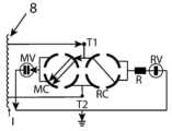
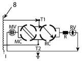
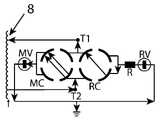
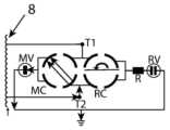
본 개시는 진공 부하시 탭 전환기 (OLTC) 를 모니터링하기 위한 방법 및 모니터링 시스템 (10) 을 제공한다. 도 1 은 디버터 스위치 (4) 의 줌인된 뷰로 진공 타입 탭 전환기의 일 예를 도시한다. 그 예에 있어서, OLTC (1) 는 절연 유체 (3) 를 갖는 하우징 (2), 디버터 스위치 (4), 압력 센서 (5) 및 탭 선택기 (6) 를 갖는 것이 도시된다. 줌인된 디버터 스위치 (4) 는 중간에 백색 정사각형을 나타낸다. 백색 정사각형은 본 개시의 목적들을 위해 나타낼 필요가 없는 디버터 스위치 (4) 의 부분들을 나타낸다. 백색 정사각형의 측면들 상에, 진공 인터럽터들 (MV, RV) 이 예시된다. 예시된 예에 있어서 각각의 위상에 대해 하나씩인 3개의 인터럽터들 (MV) 및 3개의 인터럽터들 (RV) 이 존재한다. 본 개시는 또한 단상 및 2상에 적용가능하다. 진공 인터럽터들 (MV, RV) 은 요크 (7) 에 의해 개방 및 폐쇄된다. 요크가 3개의 진공 인터럽터를 동시에 개방하는 것은 진공 인터럽터들을 개방 및 폐쇄하는 방법의 일 예임을 유의한다. 다른 방법들이 가능하다.The present disclosure provides a method and
도 2 에서, 단순화된 진공 인터럽터 설계가 도시되며, 여기서, 각각의 위상에 대해 하나씩인 3개의 진공 인터럽터들 (MV, RV) 의 2개의 세트들이 요크 (7) 에 의해 동시에 개방 및 폐쇄된다. 도면의 좌측 부분에서는, 3개의 진공 인터럽터들이 폐쇄되고, 우측 부분에서는 개방된다.In FIG. 2 , a simplified vacuum interrupter design is shown, in which two sets of three vacuum interrupters (MV, RV), one for each phase, are simultaneously opened and closed by the
도 3a 내지 도 3k 는 OLTC (1) 에서 탭을 변경하는 단순화된 단계별 프로세스를 도시한다. 이 경우, 디버터 스위치 (4) 의 가동 컨택은 디버터 스위치 (4) 의 메인 측 상의 회전가능한 메인 보조 컨택 (MC) 및 디버터 스위치 (4) 의 저항기 측 상의 저항기 보조 컨택 (RC) 이다. 도면들은 예시적인 목적들로 OLTC (1) 의 단순화된 뷰를 도시한다. 오직 하나의 가동 컨택을 갖는 OLTC들이 존재함을 유의한다. 화살표들은 OLTC (1) 를 통한 전류 경로를 표시한다. 탭 권선 (8) 에서의 좌측으로 볼 수 있는 바와 같이, T1 상으로의 연결은 T2 상으로의 연결과는 상이한 양의 탭 권선 턴들을 제공한다.3A-3K show a simplified step-by-step process for changing taps in OLTC (1). In this case, the movable contacts of the
도 3a 에 있어서, 탭 (T1) 에 대한 서비스 포지션이 도시된다. 탭 (T2) 으로 스위칭하기 위한 단계들이 도 3b 내지 도 3k 에 도시된다. 도 3b 에 있어서, 메인 진공 인터럽터 (MV) 가 개방되고, 진공 병에 아크가 존재한다. 아크가 중지하였을 때, 도 3c 에 도시된 바와 같이, 모든 전류가 저항기 측을 통과할 것이다. 메인 진공 인터럽터 (MV) 를 개방한 채로 유지하면, 메인 보조 컨택 (MC) 이 이제 도 3d 에 도시된 바와 같이 회전된다. 도 3e 에 도시된 바와 같이, 메인 보조 컨택 (MC) 은 이제, 탭 (T2) 에 연결하기 위해 완전히 회전되지만, 메인 진공 인터럽터 (MV) 는 전류가 저항기 측을 여전히 통과하도록 여전히 개방된다. 도 3f 에 도시된 바와 같이, 메인 진공 인터럽터 (MV) 는 이제 폐쇄되고, 부하 전류는 이제 MV 로 가고, 순환 전류가, T1 과 T2 사이의 전압 차이로 인해, MV 및 RV 를 통해 시작한다. 도 3g 에 도시된 다음 단계에서, 저항기 진공 인터럽터 (RV) 가 개방되고, 그 안에 순환 전류에 의해 아크가 존재한다. 부하 전류는 이에 의해 영향을 받지 않고 동일하게 유지된다. 아크가 정지하였을 때, T1 을 통한 순환 전류 경로가 정지된다. 부하 전류는 도 3h 에 도시된 바와 같이 T2 를 계속 통과한다. 저항기 보조 컨택 (RC) 은 도 3i 에 도시된 바와 같이 회전된다. 도 3j 에 있어서, 저항기 보조 컨택 (RC) 은 제위치에 있지만, 저항기 진공 인터럽터 (RV) 는 여전히 개방된다. 이는, 탭 (T2) 에 대한 서비스 포지션인 도 3k 에 도시된 바와 같이 다음 단계에서 폐쇄된다. 도면들에서, 저항기 측은 또한 연결된 저항기 (R) 를 갖는다.In FIG. 3A, the service position for tap T1 is shown. Steps for switching to tap T2 are shown in FIGS. 3b-3k. In FIG. 3B, the main vacuum interrupter (MV) is open and there is an arc in the vacuum bottle. When the arc stops, all current will pass through the resistor side, as shown in Figure 3c. Keeping the main vacuum interrupter (MV) open, the main auxiliary contact (MC) is now rotated as shown in FIG. 3D. As shown in FIG. 3E, the main auxiliary contact (MC) is now fully rotated to connect to tap (T2), but the main vacuum interrupter (MV) is still open so that current still passes through the resistor side. As shown in FIG. 3F, the main vacuum interrupter (MV) is now closed, the load current now goes to MV, and a circulating current starts through MV and RV due to the voltage difference between T1 and T2. In the next step shown in Fig. 3g, the resistor vacuum interrupter (RV) is opened, and an arc is present therein by means of a circulating current. The load current is unaffected by this and remains the same. When the arc stops, the circulating current path through T1 stops. The load current continues to pass through T2 as shown in FIG. 3H. The resistor auxiliary contact (RC) is rotated as shown in FIG. 3I. 3j, the resistor auxiliary contact (RC) is in place, but the resistor vacuum interrupter (RV) is still open. This is closed in the next step as shown in Fig. 3k, the service position for tap T2. In the drawings, the resistor side also has a connected resistor R.
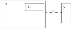
도 4 는 진공 부하시 탭 전환기 (1) 를 위한 모니터링 시스템 (10) 의 일 예시를 도시한다. 전술된 바와 같이, OLTC (1) 는 절연 유체 (3) 로 충진된 하우징 (2), 하우징 (2) 의 내부에 배열되고 적어도 하나의 가동 컨택 (MC, RC) 및 적어도 하나의 가동 컨택을 통해 전류를 인터럽트하기 위한 적어도 2개의 진공 인터럽터들 (MV, RV) 을 포함하는 디버터 스위치 (4) 를 포함한다. 적어도 하나의 가동 컨택은 비물리적 방식으로 가동일 수도 있음을 유의해야 한다. 즉, 적어도 하나의 가동 컨택은, 예를 들어, 전기 시스템이 전류를 재지향시켜 컨택을 이동시킨다는 의미에서 가동일 수도 있다.4 shows an example of a
모니터링 시스템 (10) 은 적어도 2개의 진공 인터럽터들 (MV, RV) 의 개방 및 폐쇄를 검출하기 위해 하우징(2) 에서의 압력을 측정하는 적어도 하나의 압력 센서 (5), 및 프로세싱 회로부 (11) 를 포함한다. 압력 센서 (5) 는, OLTC (1) 의 하우징 (2) 의 상부에 배열되는 도 1 에서도 또한 예시된다. 압력 센서는 디버터 스위치 하우징의 상부의 측면 상에 배치될 수도 있다. 이는 또한 디버터 스위치 하우징의 커버, 즉, 최상부에 배치될 수 있다. 프로세싱 회로부 (11) 는 어떤 종류의 통신 수단 (9) 을 통해 압력 센서 (5) 로부터 센서 데이터를 수신한다. 통신 수단은, 예를 들어, Wi-Fi, 블루투스, Z-웨이브 또는 지그비를 통한 임의의 종류의 통신, 유선 통신 또는 무선 통신일 수도 있다. 프로세싱 회로부 (11) 와 압력 센서 (5) 사이의 통신에 대한 대안들은 당업자에게 공지되어 있고, 추가로 논의되지 않을 것이다.The
도 5 에 있어서, 예시적인 진공 인터럽터가 좌측에는 폐쇄 포지션으로 및 우측에는 개방 포지션으로 도시된다. 컨택들 (12) 은 폐쇄 포지션에서 인접하고 개방 포지션에서 분리된다. 컨택들 주위의 하우징 (2) 에는, 진공 (13) 이 존재한다. 도면에서 알 수 있는 바와 같이, 진공 인터럽터가 OLTC (1) 에서 사용하는 체적은, 진공 인터럽터가 개방될 때 증가한다. 따라서, 절연 유체 (3) 에서의 압력은 진공 인터럽터가 개방될 때 증가한다.5, an exemplary vacuum interrupter is shown in a closed position on the left and in an open position on the right.
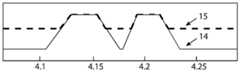
프로세싱 회로부 (11) 는 미리결정된 시간 인터벌 내에서 2개의 후속 피크들을 포함하는 압력 시그너처 (14) 를 결정하도록 배열되고, 여기서, 최대 압력은 미리결정된 레벨을 초과하지 않는다. 그 결정은 메모리로부터 압력 시그너처 (14) 를 판독하거나, 그렇지 않으면, 외부 소스로부터 압력 시그너처를 수신하는 것일 수도 있다. 예시적인 압력 시그너처 (14) 가 도 6 에 예시된다. 예시된 압력 시그너처 (14) 는, 2개의 요크들 (7) 이 3개의 진공 인터럽터들의 개별 세트를 개방 및 폐쇄하는 도 1 에 예시된 바와 같은 셋업으로부터의 것이다. 압력 시그너처 (14) 는 요크 (7) 움직임 및 진공 인터럽터들의 체적 증가 (15) 의 결과이다. x축의 숫자들은 초 단위의 시간을 나타낸다. 그리고 y축은 압력의 양이다. 압력의 양 및 시간은 OLTC들 (1) 사이에서 변할 것이며, 단지 예시적인 목적들일 뿐이다. 2개의 후속 피크들을 갖는 압력 시그너처 (14) - 여기서, 양자의 피크들은 미리결정된 시간 인터벌 내에 있음 - 는, 2개의 탭들 사이의 스위치가 OLTC (1) 에서 수행되었음을 나타낸다. 압력이 먼저 제 1 피크 상에서 상승한 경우, 메인 진공 인터럽터는 개방되었다, 도 3b 참조. 압력은 메인 진공 인터럽터가 폐쇄될 때 강하한다, 도 3f 참조. 제 2 피크는 저항기 진공 인터럽터가 개방될 때이고, 도 3g 참조; 폐쇄된다, 도 3k 참조.
프로세싱 회로부 (11) 는 압력 센서 (5) 로 하우징 (2) 에서의 압력을 계속적으로 측정하고, 측정된 압력이 압력 시그너처 (14) 를 나타낼 때를 검출한다. 따라서, 탭 스위치가 발생하였다. 그 다음, 프로세싱 회로부 (11) 는, 압력 시그너처 (14) 내에서의 측정된 압력에 기초하여, 압력에서의 제 1 상승과 제 2 강하 사이의 시간을 결정하고, 결정된 시간을 디버터 스위치 (4) 의 스위치 시간을 나타내도록 설정한다. 이러한 모니터링 시스템 (10) 으로, 스위치 시간이 따라서 결정될 수 있다. 스위치 시간을 결정함으로써, 저속 동작이 검출될 수 있다.
진공 부하시 탭 전환기 (1) (OLTC) 를 모니터링하기 위한 방법이 도 7 에 예시된다. 실선을 갖는 박스들은 가장 넓은 실시형태에서의 방법의 단계들을 예시하고, 점선들을 갖는 박스들은 대안적인 단계들을 나타낸다. 단계들은 예시된 순서를 벗어나서 발생할 수도 있음을 유의해야 한다. 그 방법은, 미리결정된 시간 인터벌 내에서 2개의 후속 피크들을 포함하는 압력 시그너처 (14) 를 결정하는 단계로서, 최대 압력은 미리결정된 레벨을 초과하지 않는, 상기 압력 시그너처 (14) 를 결정하는 단계, 압력 센서 (5) 로 하우징 (2) 에서의 압력을 계속적으로 측정하는 단계, 측정된 압력이 압력 시그너처 (14) 를 나타낼 때를 검출하는 단계, 압력 시그너처 (14) 내에서의 측정된 압력에 기초하여, 압력에서의 제 1 상승과 제 2 강하 사이의 시간을 결정하는 단계, 및 결정된 시간을 디버터 스위치 (4) 의 스위치 시간을 나타내도록 설정하는 단계를 포함한다. 따라서, 그 방법의 단계들은 모니터링 시스템 (10) 에서의 프로세싱 회로부 (11) 의 단계들과 동일하고, 동일한 이점들을 갖는다.A method for monitoring a vacuum on-load tap changer 1 (OLTC) is illustrated in FIG. 7 . Boxes with solid lines illustrate steps of the method in the broadest embodiment, boxes with dotted lines indicate alternative steps. It should be noted that steps may occur out of the illustrated order. The method comprises the steps of determining a pressure signature (14) comprising two subsequent peaks within a predetermined time interval, wherein a maximum pressure does not exceed a predetermined level; continuously measuring the pressure in the housing (2) with the pressure sensor (5), detecting when the measured pressure is indicative of the pressure signature (14), based on the measured pressure within the pressure signature (14) to determine the time between the first rise and the second drop in pressure, and setting the determined time to indicate the switch time of the diverter switch (4). Accordingly, the steps of the method are identical to those of the
모니터링 시스템 (10) 및 압력 센서 (5) 로 검출될 수도 있는 수개의 다른 것들이 존재한다. 일부 양태들에 따르면, 프로세싱 회로부 (11) 는, 제 2 피크가 후속 강하를 나타내지 않지만 측정된 압력이 압력 시그너처 (14) 를 나타낼 때를 검출하고, 그리고 진공 부하시 탭 전환기 (1) 가 오작동하고 있음과 안전한 포지션에 도달하였음을 표시하는 알람을 활성화하도록 배열된다. 그 방법은 또한 동일한 단계들을 포함할 수도 있다. 제 2 피크가 강하를 나타내지 않는다는 것은 제 2 진공 인터럽터가 폐쇄되지 않았다는 것을 나타낸다. 즉, OLTC (1) 는 안전한 포지션인 도 3j 에 도시된 바와 같은 포지션에 고정된다. 전술된 바와 같이, 알람은 OLTC (1) 의 오퍼레이터에 대한 임의의 종류의 표시이다. 따라서, 오퍼레이터는, OLTC (1) 가 오작동하고 있지만 RV 진공 인터럽터가 폐쇄되지 않은 안전한 포지션에 도달하였음을 통지받을 수 있다. 그 다음, 적절한 액션들이 오퍼레이터에 의해 취해질 수 있다. 예시적인 액션들은 오일 샘플을 취하고, 가스 함량 (DGA) 을 체크하고, 탭-전환기의 동작을 중지시키는 것이다. 추가적인 단계는 진공 부하시 탭 전환기 (1) 의 스테이터스를 안전한 포지션에서 오작동하는 것으로 설정하는 것일 수도 있다.There are several others that may be detected with
원치않은 아킹이 OLTC (1) 에서 발생할 때 가스가 생성된다. 따라서, 하우징 (2) 에 가스가 존재할 수도 있다. 일부 양태들에 따르면, 프로세싱 회로부 (11) 는, 측정된 압력이 압력 시그너처 (14) 를 나타낼 때 및 피크들에서의 압력이 미리결정된 압력 레벨을 초과하지 않을 때를 검출하고, 그리고 진공 부하시 탭 전환기 (1) 가 가스 생성 이벤트를 가졌음을 표시하는 알람을 활성화하도록 배열된다. 그 방법은 또한 동일한 단계들을 포함할 수도 있다. 그 다음, 오퍼레이터는 적절한 액션을 취할 수 있다. 피크들에서의 압력이 미리결정된 수의 동작들에 대해 미리결정된 레벨보다 낮으면, 하우징 (2) 에서의 자유 가스가 제거되지 않았기 때문에, OLTC (1) 는 동작에 대해 차단될 수도 있다. 하우징 (2) 에 가스가 존재할 때, 압력 시그너처 (14) 의 피크들은 하우징 (2) 에 가스가 없을 때만큼 높지 않을 것이고, 따라서, 가스가 존재하지 않을 때, 피크들에서의 압력이 정상보다 낮음을 결정함으로써 하우징 (2) 에서의 가스를 검출하는 것이 가능하다. 추가적인 단계는 진공 부하시 탭 전환기 (1) 의 스테이터스를 하우징 (2) 에서의 가스로 오작동하는 것으로 설정하는 것일 수도 있다.Gases are produced when unwanted arcing occurs in the OLTC (1). Thus, gas may be present in the
OLTC (1) 에서의 예상치않은 압력 펄스들은, 폭발이 존재하는 위험한 상황을 초래할 수도 있다. 진공 인터럽터들이 제공해야 하는 레벨 초과의 예상치않은 압력 펄스는 디버터 스위치에서의 일부 포인트에서 오일에서의 아킹을 나타낼 수 있다. 진공 타입의 탭 전환기에서 이러한 종류의 압력 펄스들을 일으키는 오일에서의 아킹은 존재하지 않아야 한다. 진공 인터럽터가 파손되지 않으면, 대부분의 경우들에 있어서, 이는 아크를 야기하는 진공 인터럽터 파손과 관련된 보조 컨택일 것이다. 따라서, 일부 양태들에 따르면, 프로세싱 회로부 (11) 는 추가로, 미리결정된 최대 레벨 초과의 압력을 갖는 압력 펄스를 검출하고, 그리고 진공 부하시 탭 전환기 (1) 가 안전하게 동작하고 있지 않다는 알람을 활성화하도록 배열된다. 그 방법은 또한 동일한 단계들을 포함할 수도 있다. 따라서, 오퍼레이터는 OLTC (1) 가 안전하지 않은 방식으로 오작동하고 있음을 경보받는다. 일부 양태들에 따르면, OLTC (1) 는 미리결정된 최대 레벨 초과의 압력을 검출할 때 즉시 셧다운된다. 추가적인 단계는 진공 부하시 탭 전환기 (1) 의 스테이터스를 위험하게 오작동하는 것으로 설정하는 것일 수도 있다.Unexpected pressure pulses in the
하우징 (2) 에서의 절연 유체 (3) 의 양은, 예를 들어, 누설들로 인해, 시간에 걸쳐 서서히 감소할 수도 있다. 일부 OLTC들에서, OLTC 위에 배치된 콘서베이터 (conservator) (16) 로부터 절연 유체 (3) 를 재충진하기 위한 시스템이 존재한다. 일부 양태들에 따르면, 프로세싱 회로부 (11) 는 추가로, 하우징 (2) 에서의 정적 압력의 양을 검출하고, 그리고 정적 압력의 양에 기초하여 절연 유체 (3) 의 양을 결정하도록 배열된다. 따라서, 정적 압력은, 절연 유체 (3) 의 양이 감소하면 정적 압력이 감소할 것이기 때문에, 하우징 (2) 에 및 대안적으로 콘서베이터 (16) 에 얼마나 많은 절연 유체 (3) 가 존재하는지를 결정하는데 사용된다. 압력 피크들이 존재하지 않을 때라도, 하우징 (2) 에서의 일부 압력이 항상 존재할 것이다. 그 정적 압력은, 절연 유체 (3) 의 양이 하우징 (2) 에서 변하면, 시간에 걸쳐 변할 수도 있다. 따라서, 정적 압력에서의 변동들은 하우징 (2) 에서의 절연 유체 (3) 의 양의 표시를 제공한다. 그 정보는, 절연 유체 (3) 가 재충진되어야 하는 정도 및 시간을 결정하는 데 사용될 수 있다. 그 방법은 또한 동일한 단계들을 포함할 수도 있다. 추가적인 단계는 진공 부하시 탭 전환기 (1) 의 스테이터스를, 더 많은 절연 유체 (3) 를 필요로 하는 것으로 설정하는 것일 수도 있다.The amount of insulating
하우징 (2) 에 충분한 절연 유체 (3) 가 존재하지 않은 것이 장기간에 걸쳐 검출되었다면, 알람을 활성화하기 위한 필요가 있을 수도 있다. 일부 양태들에 따르면, 프로세싱 회로부 (11) 는 추가로, 절연 유체 (3) 의 결정된 양이 미리결정된 인터벌의 밖에 있을 때 하우징 (2) 에서의 절연 유체 (3) 의 레벨이 조정되어야 함을 표시하는 알람을 활성화하도록 배열된다. 그 방법은 또한 동일한 단계를 포함할 수도 있다. 따라서, 정적 압력이 너무 많이 변해서 오퍼레이터가 통지받을 필요가 있을 때 알람이 존재한다.If it has been detected over a long period of time that there is not enough insulating
본 발명은 개시된 실시형태들로 한정되지 않고, 다음의 청구항들의 범위 내에서 변경 및 수정될 수도 있다.The invention is not limited to the disclosed embodiments, but may be varied and modified within the scope of the following claims.
1. 진공 부하시 탭 전환기, OLTC
2. 하우징
3. 절연 유체
4. 디버터 스위치
T1 = 탭 권선 상의 하나의 탭
T2 = 탭 권선 상의 다른 탭
RV = 저항기 진공 인터럽터
MV = 메인 진공 인터럽터
RC = 저항기 보조 컨택
MC = 메인 보조 컨택
R = 저항기
5. 압력 센서
6. 탭 선택기
7. 요크
8. 탭 권선
9. 통신 수단
10. 모니터링 시스템
11. 프로세싱 회로부
12. 컨택
13. 진공
14. 압력 시그너처
15. 진공 인터럽터 움직임에 의한 압력 증가
16. 콘서베이터1. Vacuum on-load tap changer, OLTC
2. Housing
3. Insulation fluid
4. Diverter switch
T1 = one tap on the tapped winding
T2 = another tap on the tapped winding
RV = resistor vacuum interrupter
MV = main vacuum interrupter
RC = resistor auxiliary contact
MC = main secondary contact
R = resistor
5. Pressure sensor
6. Tab selector
7. York
8. Tap winding
9. Means of communication
10. Monitoring system
11. Processing circuitry
12. Contact
13. Vacuum
14. Pressure signature
15. Pressure increase by movement of vacuum interrupter
16. Conservator
Claims (12)
Translated fromKorean상기 탭 전환기 (1) 는,
- 절연 유체 (3) 로 충진된 하우징 (2),
- 상기 하우징 (2) 의 내부에 배열되고 적어도 하나의 가동 컨택 (MC, RC) 및 상기 적어도 하나의 가동 컨택을 통해 전류를 인터럽트하기 위한 메인 진공 인터럽터 (MV) 및 저항기 진공 인터럽터 (RV) 를 포함하는 적어도 2개의 진공 인터럽터들을 포함하는 디버터 스위치 (4),
- 상기 하우징 (2) 에서의 압력을 측정하는 적어도 하나의 압력 센서 (5) 를 포함하고,
상기 방법은,
- 미리결정된 시간 인터벌 내에서 2개의 후속 피크들을 포함하는 압력 시그너처 (14) 를 결정하는 단계 (S1) 로서, 상기 피크들의 제 1 피크는 상기 메인 진공 인터럽터 (MV) 가 개방된 것에 대응하고, 상기 피크들의 제 2 피크는 상기 저항기 진공 인터럽터가 개방된 것에 대응하고, 최대 압력은 미리결정된 레벨을 초과하지 않는, 상기 압력 시그너처 (14) 를 결정하는 단계 (S1),
- 상기 메인 진공 인터럽터 및 상기 저항기 진공 인터럽터의 개방 및 폐쇄를 검출하기 위해, 상기 압력 센서 (5) 로 상기 하우징 (2) 에서의 상기 압력을 계속적으로 측정하는 단계 (S2) 로서, 상기 압력은 개개의 진공 인터럽터들이 개방될 때 증가하고, 폐쇄될 때 강하하는, 상기 하우징 (2) 에서의 상기 압력을 계속적으로 측정하는 단계 (S2),
- 측정된 상기 압력이 상기 압력 시그너처 (14) 를 나타낼 때를 검출하는 단계 (S3),
- 상기 압력 시그너처 (14) 내에서의 상기 측정된 압력에 기초하여, 압력에서의 제 1 상승과 제 2 강하 사이의 시간을 결정하는 단계 (S4), 및
- 결정된 상기 시간을 상기 디버터 스위치 (4) 의 스위치 시간을 나타내도록 설정하는 단계 (S5) 를 포함하는, 진공 부하시 탭 전환기 (1) 를 모니터링하기 위한 방법.As a method for monitoring a vacuum on-load tap changer (1),
The tap changer (1),
- a housing (2) filled with insulating fluid (3);
- arranged inside the housing 2 and comprising at least one movable contact (MC, RC) and a main vacuum interrupter (MV) and a resistor vacuum interrupter (RV) for interrupting the current through the at least one movable contact a diverter switch (4) comprising at least two vacuum interrupters that
- at least one pressure sensor (5) measuring the pressure in the housing (2),
The method,
- determining (S1) a pressure signature (14) comprising two subsequent peaks within a predetermined time interval, the first of which corresponds to the opening of the main vacuum interrupter (MV), said determining (S1) the pressure signature (14), wherein a second peak of peaks corresponds to the resistor vacuum interrupter being opened, and a maximum pressure does not exceed a predetermined level;
- continuously measuring (S2) the pressure in the housing (2) with the pressure sensor (5) to detect the opening and closing of the main vacuum interrupter and the resistor vacuum interrupter, wherein the pressure is individually continuously measuring (S2) the pressure in the housing (2), which increases when the vacuum interrupters of , and drops when they are closed;
- detecting when the measured pressure indicates the pressure signature (14) (S3);
- determining (S4) the time between the first rise and the second drop in pressure, based on the measured pressure in the pressure signature (14), and
- setting (S5) said determined time to represent the switch time of said diverter switch (4).
- 상기 제 2 피크가 후속 강하를 나타내지 않지만 상기 측정된 압력이 상기 압력 시그너처 (14) 를 나타낼 때를 검출하는 단계 (S6), 및
- 상기 진공 부하시 탭 전환기 (1) 가 오작동하고 있음과 안전한 포지션에 도달하였음을 표시하는 알람을 활성화하는 단계 (S7) 를 포함하는, 진공 부하시 탭 전환기 (1) 를 모니터링하기 위한 방법.According to claim 1,
- detecting (S6) when the second peak does not indicate a subsequent drop but the measured pressure indicates the pressure signature (14), and
- activating (S7) an alarm indicating that said vacuum on-load tap changer (1) is malfunctioning and that a safe position has been reached.
- 상기 측정된 압력이 상기 압력 시그너처 (14) 를 나타낼 때 및 상기 피크들에서의 압력이 미리결정된 압력 레벨을 초과하지 않을 때를 검출하는 단계 (S8), 및
- 상기 진공 부하시 탭 전환기 (1) 가 가스 생성 이벤트를 가졌음을 표시하는 알람을 활성화하는 단계 (S9) 를 포함하는, 진공 부하시 탭 전환기 (1) 를 모니터링하기 위한 방법.According to claim 1,
- detecting (S8) when the measured pressure indicates the pressure signature (14) and when the pressure at the peaks does not exceed a predetermined pressure level, and
- activating (S9) an alarm indicating that said vacuum on-load tap changer (1) has had a gas production event.
- 미리결정된 최대 레벨 초과의 압력을 갖는 압력 펄스를 검출하는 단계 (S10), 및
- 상기 진공 부하시 탭 전환기 (1) 가 안전하게 동작하고 있지 않다는 알람을 활성화하는 단계 (S11) 를 포함하는, 진공 부하시 탭 전환기 (1) 를 모니터링하기 위한 방법.According to claim 1,
- detecting (S10) a pressure pulse having a pressure above a predetermined maximum level, and
- a step (S11) of activating an alarm that said vacuum on-load tap changer (1) is not operating safely.
- 상기 하우징 (2) 에서의 정적 압력의 양을 검출하는 단계 (S12), 및
- 상기 정적 압력의 양에 기초하여 상기 절연 유체 (3) 의 양을 결정하는 단계 (S13) 를 포함하는, 진공 부하시 탭 전환기 (1) 를 모니터링하기 위한 방법.According to any one of claims 1 to 4,
- detecting (S12) the amount of static pressure in said housing (2), and
- determining (S13) the quantity of the insulating fluid (3) based on the quantity of the static pressure;
- 상기 절연 유체 (3) 의 결정된 양이 미리결정된 인터벌의 밖에 있을 때 상기 하우징 (2) 에서의 상기 절연 유체 (3) 의 레벨이 조정되어야 함을 표시하는 알람을 활성화하는 단계 (S14) 를 포함하는, 진공 부하시 탭 전환기 (1) 를 모니터링하기 위한 방법.According to claim 5,
- activating (S14) an alarm indicating that the level of the insulating fluid (3) in the housing (2) is to be adjusted when the determined amount of the insulating fluid (3) is outside a predetermined interval. method for monitoring a vacuum on-load tap changer (1).
상기 진공 부하시 탭 전환기 (1) 는 절연 유체 (3) 로 충진된 하우징 (2), 상기 하우징 (2) 의 내부에 배열되고 적어도 하나의 가동 컨택 (MC, RC) 및 상기 적어도 하나의 가동 컨택을 통해 전류를 인터럽트하기 위한 메인 진공 인터럽터 (MV) 및 저항기 진공 인터럽터 (RV) 를 포함하는 적어도 2개의 진공 인터럽터들을 포함하는 디버터 스위치 (4) 를 포함하고,
상기 모니터링 시스템 (10) 은,
- 상기 하우징 (2) 에서의 압력을 측정하는 적어도 하나의 압력 센서 (5),
- 프로세싱 회로부 (11) 를 포함하고,
상기 프로세싱 회로부 (11) 는,
■ 미리결정된 시간 인터벌 내에서 2개의 후속 피크들을 포함하는 압력 시그너처 (14) 를 결정하는 것으로서, 상기 피크들의 제 1 피크는 상기 메인 진공 인터럽터 (MV) 가 개방된 것에 대응하고, 상기 피크들의 제 2 피크는 상기 저항기 진공 인터럽터가 개방된 것에 대응하고, 최대 압력은 미리결정된 레벨을 초과하지 않는, 상기 압력 시그너처 (14) 를 결정하고,
■ 상기 메인 진공 인터럽터 및 상기 저항기 진공 인터럽터의 개방 및 폐쇄를 검출하기 위해, 상기 압력 센서 (5) 로 상기 하우징 (2) 에서의 상기 압력을 계속적으로 측정하는 것으로서, 상기 압력은 개개의 진공 인터럽터들이 개방될 때 증가하고, 폐쇄될 때 강하하는, 상기 하우징 (2) 에서의 상기 압력을 계속적으로 측정하고,
■ 측정된 상기 압력이 상기 압력 시그너처 (14) 를 나타낼 때를 검출하고,
■ 상기 압력 시그너처 (14) 내에서의 상기 측정된 압력에 기초하여, 압력에서의 제 1 상승과 제 2 강하 사이의 시간을 결정하고, 그리고
■ 결정된 상기 시간을 상기 디버터 스위치 (4) 의 스위치 시간을 나타내도록 설정하도록
배열되는, 모니터링 시스템 (10).As a monitoring system (10) for a vacuum on-load tap changer (1),
The vacuum on-load tap changer (1) comprises a housing (2) filled with an insulating fluid (3), at least one movable contact (MC, RC) arranged inside the housing (2) and said at least one movable contact a diverter switch (4) comprising at least two vacuum interrupters comprising a main vacuum interrupter (MV) and a resistor vacuum interrupter (RV) for interrupting the current through
The monitoring system 10,
- at least one pressure sensor (5) measuring the pressure in said housing (2);
- comprises processing circuitry (11),
The processing circuitry 11,
■ determining a pressure signature (14) comprising two subsequent peaks within a predetermined time interval, a first of the peaks corresponding to the main vacuum interrupter (MV) being open and a second of the peaks corresponding to the opening of the main vacuum interrupter (MV); determining the pressure signature (14), wherein a peak corresponds to the resistor vacuum interrupter being open, and a maximum pressure does not exceed a predetermined level;
■ Continuously measuring the pressure in the housing (2) with the pressure sensor (5) to detect the opening and closing of the main vacuum interrupter and the resistor vacuum interrupter, the pressure being determined by the individual vacuum interrupters. continuously measuring the pressure in the housing (2), which increases when open and drops when closed;
■ detect when the measured pressure indicates the pressure signature (14);
■ based on the measured pressure in the pressure signature (14), determine the time between the first rise and the second drop in pressure; and
■ to set the determined time to indicate the switch time of the diverter switch (4)
Arranged, a monitoring system (10).
상기 프로세싱 회로부 (11) 는 추가로,
■ 상기 제 2 피크가 후속 강하를 나타내지 않지만 상기 측정된 압력이 상기 압력 시그너처 (14) 를 나타낼 때를 검출하고, 그리고
■ 상기 진공 부하시 탭 전환기 (1) 가 오작동하고 있음과 안전한 포지션에 도달하였음을 표시하는 알람을 활성화하도록
배열되는, 모니터링 시스템 (10).According to claim 7,
The processing circuitry 11 further comprises:
■ detecting when the second peak does not indicate a subsequent drop but the measured pressure indicates the pressure signature (14); and
■ To activate an alarm indicating that the vacuum on-load tap changer (1) is malfunctioning and has reached a safe position.
Arranged, a monitoring system (10).
상기 프로세싱 회로부 (11) 는 추가로,
■ 상기 측정된 압력이 상기 압력 시그너처 (14) 를 나타낼 때 및 상기 피크들에서의 압력이 미리결정된 압력 레벨을 초과하지 않을 때를 검출하고, 그리고
■ 상기 진공 부하시 탭 전환기 (1) 가 가스 생성 이벤트를 가졌음을 표시하는 알람을 활성화하도록
배열되는, 모니터링 시스템 (10).According to claim 7,
The processing circuitry 11 further comprises:
■ detect when the measured pressure exhibits the pressure signature 14 and when the pressure at the peaks does not exceed a predetermined pressure level; and
■ to activate an alarm indicating that the vacuum on-load tap changer (1) has had a gassing event;
Arranged, a monitoring system (10).
상기 프로세싱 회로부 (11) 는 추가로,
■ 미리결정된 최대 레벨 초과의 압력을 갖는 압력 펄스를 검출하고, 그리고
■ 상기 진공 부하시 탭 전환기 (1) 가 안전하게 동작하고 있지 않다는 알람을 활성화하도록
배열되는, 모니터링 시스템 (10).According to claim 7,
The processing circuitry 11 further comprises:
■ detecting a pressure pulse having a pressure above a predetermined maximum level; and
■ To activate an alarm that the vacuum on-load tap changer (1) is not operating safely.
Arranged, a monitoring system (10).
상기 프로세싱 회로부 (11) 는 추가로,
■ 상기 하우징 (2) 에서의 정적 압력의 양을 검출하고, 그리고
■ 상기 정적 압력의 양에 기초하여 상기 절연 유체 (3) 의 양을 결정하도록
배열되는, 모니터링 시스템 (10).According to any one of claims 7 to 10,
The processing circuitry 11 further comprises:
■ detect the amount of static pressure in the housing (2), and
■ to determine the amount of the insulating fluid (3) based on the amount of the static pressure
Arranged, a monitoring system (10).
상기 프로세싱 회로부 (11) 는 추가로,
■ 상기 절연 유체 (3) 의 결정된 양이 미리결정된 인터벌의 밖에 있을 때 상기 하우징 (2) 에서의 상기 절연 유체 (3) 의 레벨이 조정되어야 함을 표시하는 알람을 활성화하도록 배열되는, 모니터링 시스템 (10).According to claim 11,
The processing circuitry 11 further comprises:
■ a monitoring system, arranged to activate an alarm indicating that the level of the insulating fluid (3) in the housing (2) should be adjusted when the determined amount of the insulating fluid (3) is outside a predetermined interval ( 10).
Applications Claiming Priority (3)
| Application Number | Priority Date | Filing Date | Title |
|---|---|---|---|
| EP19177143.5AEP3745434B1 (en) | 2019-05-28 | 2019-05-28 | Pressure pulse diagnostics of an on-load tap changer |
| EP19177143.5 | 2019-05-28 | ||
| PCT/EP2020/063867WO2020239511A1 (en) | 2019-05-28 | 2020-05-18 | Pressure pulse diagnostics of an on-load tap changer |
Publications (2)
| Publication Number | Publication Date |
|---|---|
| KR20210149226A KR20210149226A (en) | 2021-12-08 |
| KR102498649B1true KR102498649B1 (en) | 2023-02-09 |
Family
ID=66676289
Family Applications (1)
| Application Number | Title | Priority Date | Filing Date |
|---|---|---|---|
| KR1020217038923AActiveKR102498649B1 (en) | 2019-05-28 | 2020-05-18 | Diagnosis of pressure pulses on on-load tap-changers |
Country Status (5)
| Country | Link |
|---|---|
| US (1) | US11574776B2 (en) |
| EP (1) | EP3745434B1 (en) |
| KR (1) | KR102498649B1 (en) |
| CN (1) | CN114175197B (en) |
| WO (1) | WO2020239511A1 (en) |
Families Citing this family (4)
| Publication number | Priority date | Publication date | Assignee | Title |
|---|---|---|---|---|
| EP3745434B1 (en) | 2019-05-28 | 2023-05-17 | Hitachi Energy Switzerland AG | Pressure pulse diagnostics of an on-load tap changer |
| DE102022106774A1 (en)* | 2022-03-23 | 2023-09-28 | Maschinenfabrik Reinhausen Gmbh | CONDITION ANALYSIS OF A LOAD TAP SWITCH |
| EP4307329B1 (en) | 2022-07-14 | 2025-03-05 | Hitachi Energy Ltd | Pressure pulse diagnostics of an on-load tap changer |
| CN119480491A (en)* | 2024-10-10 | 2025-02-18 | 国网北京市电力公司 | Phase-changing switch and electric power equipment having the same |
Family Cites Families (21)
| Publication number | Priority date | Publication date | Assignee | Title |
|---|---|---|---|---|
| US3206569A (en) | 1964-12-17 | 1965-09-14 | Orin P Mccarty | Protective means for transformer tap changer |
| KR840008521A (en) | 1983-04-20 | 1984-12-15 | 문재경 | Cutting ON / OFF switch of the instrument with a transformer |
| AU2067895A (en) | 1994-03-09 | 1995-09-25 | Maschinenfabrik Reinhausen Gmbh | Switching arrangement for load change-over switches of step switches and for selector switches |
| EP1350292B1 (en)* | 2000-12-15 | 2010-11-10 | ABB T & D Technology Ltd. | Condition diagnosing |
| US7145760B2 (en)* | 2000-12-15 | 2006-12-05 | Abb Technology Ltd. | Tap changer monitoring |
| US7885043B2 (en) | 2007-06-15 | 2011-02-08 | General Electric Company | Remote-operable micro-electromechanical system based over-current protection apparatus |
| BRPI0910767A2 (en)* | 2008-04-21 | 2017-08-29 | Abb Research Ltd | ARC DETECTOR AND ASSOCIATED METHOD TO DETECT UNDESIRABLE ARCS |
| EP2334114B1 (en) | 2008-09-22 | 2016-10-12 | Sharp Kabushiki Kaisha | Wireless communication system, base station device, mobile station device, and wireless communication method |
| EP2264729A1 (en)* | 2009-06-18 | 2010-12-22 | ABB Technology Ltd | Method and device for detecting failure of a vacuum interrupter of an on load tap changer |
| CN201440364U (en)* | 2009-07-21 | 2010-04-21 | 杭州永驭科技有限公司 | An on-line oil filter device for on-load tap changer |
| DE102011008959B9 (en) | 2011-01-19 | 2012-04-26 | Maschinenfabrik Reinhausen Gmbh | Step switch with vacuum interrupters |
| JP2014514748A (en) | 2011-04-02 | 2014-06-19 | マシイネンフアブリーク・ラインハウゼン・ゲゼルシヤフト・ミツト・ベシユレンクテル・ハフツング | Load tap changer and vacuum valve for the load tap changer |
| US9442150B2 (en)* | 2011-12-16 | 2016-09-13 | Virginia Transformer Corporation | System and method for monitoring and controlling a transformer |
| DE102012107446B4 (en)* | 2012-08-14 | 2015-12-31 | Maschinenfabrik Reinhausen Gmbh | Diverter switch, on-load tap-changer and method of switching an on-load tap-changer |
| CH707387B1 (en)* | 2012-12-24 | 2017-01-13 | Inficon Gmbh | Measuring cell arrangement and method for vacuum pressure measurement. |
| CN103398830B (en)* | 2013-08-12 | 2016-01-20 | 贵州长征电气有限公司 | A kind of grease chamber's sealing leak hunting method of load ratio bridging switch |
| EP2899728B2 (en)* | 2014-01-22 | 2019-11-13 | ABB Schweiz AG | A device comprising a high voltage apparatus including a fluid and equipment for detecting one or more physical properties of the fluid |
| DE102015106178A1 (en) | 2015-04-22 | 2016-10-27 | Maschinenfabrik Reinhausen Gmbh | OLTC |
| CN204884832U (en)* | 2015-08-26 | 2015-12-16 | 杭州佰盟智能开关有限公司 | Hybrid on -load voltage -regulating transformer |
| CN208889457U (en)* | 2018-11-14 | 2019-05-21 | 深圳市奥电高压电气有限公司 | A kind of on-load tap changer |
| EP3745434B1 (en) | 2019-05-28 | 2023-05-17 | Hitachi Energy Switzerland AG | Pressure pulse diagnostics of an on-load tap changer |
- 2019
- 2019-05-28EPEP19177143.5Apatent/EP3745434B1/enactiveActive
- 2020
- 2020-05-18USUS17/614,657patent/US11574776B2/enactiveActive
- 2020-05-18WOPCT/EP2020/063867patent/WO2020239511A1/ennot_activeCeased
- 2020-05-18KRKR1020217038923Apatent/KR102498649B1/enactiveActive
- 2020-05-18CNCN202080054564.7Apatent/CN114175197B/enactiveActive
Also Published As
| Publication number | Publication date |
|---|---|
| EP3745434B1 (en) | 2023-05-17 |
| CN114175197B (en) | 2022-10-28 |
| KR20210149226A (en) | 2021-12-08 |
| CN114175197A (en) | 2022-03-11 |
| US11574776B2 (en) | 2023-02-07 |
| WO2020239511A1 (en) | 2020-12-03 |
| US20220148826A1 (en) | 2022-05-12 |
| EP3745434A1 (en) | 2020-12-02 |
Similar Documents
| Publication | Publication Date | Title |
|---|---|---|
| KR102498649B1 (en) | Diagnosis of pressure pulses on on-load tap-changers | |
| KR101517656B1 (en) | Method and device for detecting failure of a vacuum interrupter of an on load tap changer | |
| EP1358499B1 (en) | Tap changer monitoring | |
| US9767969B2 (en) | Subsea power switching device and methods of operating the same | |
| EP3324504B1 (en) | Monitoring tap changer switching | |
| AU2007288182A2 (en) | Vacuum based diverter switch for tap changer | |
| JP7656626B2 (en) | Device for limiting short-circuit currents in on-load tap changers and on-load tap changer having such device | |
| US9513654B2 (en) | Method for performing a switching process in an on-load tap changer | |
| US3472981A (en) | Pressure responsive protective means for vacuum type circuit interrupters immersed in liquid | |
| US20250174416A1 (en) | Pressure pulse diagnostics of an oltc | |
| WO2021028948A1 (en) | System for detecting the incomplete operation of diverter in on-load tap-changing transformers | |
| US2246182A (en) | Apparatus for transformer tap changing under load | |
| JPS6214086B2 (en) | ||
| JPH0195506A (en) | On-load tap changer | |
| JPH01295619A (en) | Abnormal state monitor for on-load tap changer | |
| KR20250036742A (en) | Method for operating an on-load tap-changer and an on-load tap-changer device | |
| JP2024141863A (en) | On-load tap changer | |
| EP3379555A1 (en) | A disconnecting system for current interruption in a transformer | |
| EP2270454A1 (en) | Time of tap changer in the same contact position | |
| JPS63128614A (en) | On-load tap changer |
Legal Events
| Date | Code | Title | Description |
|---|---|---|---|
| A302 | Request for accelerated examination | ||
| PA0105 | International application | Patent event date:20211126 Patent event code:PA01051R01D Comment text:International Patent Application | |
| PA0201 | Request for examination | ||
| PA0302 | Request for accelerated examination | Patent event date:20211126 Patent event code:PA03022R01D Comment text:Request for Accelerated Examination | |
| PG1501 | Laying open of application | ||
| E902 | Notification of reason for refusal | ||
| PE0902 | Notice of grounds for rejection | Comment text:Notification of reason for refusal Patent event date:20220429 Patent event code:PE09021S01D | |
| E701 | Decision to grant or registration of patent right | ||
| PE0701 | Decision of registration | Patent event code:PE07011S01D Comment text:Decision to Grant Registration Patent event date:20221129 | |
| GRNT | Written decision to grant | ||
| PR0701 | Registration of establishment | Comment text:Registration of Establishment Patent event date:20230207 Patent event code:PR07011E01D | |
| PR1002 | Payment of registration fee | Payment date:20230207 End annual number:3 Start annual number:1 | |
| PG1601 | Publication of registration |