KR102498505B1 - Mask apparatus - Google Patents
Mask apparatusDownload PDFInfo
- Publication number
- KR102498505B1 KR102498505B1KR1020210093992AKR20210093992AKR102498505B1KR 102498505 B1KR102498505 B1KR 102498505B1KR 1020210093992 AKR1020210093992 AKR 1020210093992AKR 20210093992 AKR20210093992 AKR 20210093992AKR 102498505 B1KR102498505 B1KR 102498505B1
- Authority
- KR
- South Korea
- Prior art keywords
- magnetic
- mounting
- face guard
- face
- front surface
- Prior art date
- Legal status (The legal status is an assumption and is not a legal conclusion. Google has not performed a legal analysis and makes no representation as to the accuracy of the status listed.)
- Active
Links
- 230000029058respiratory gaseous exchangeEffects0.000claimsabstractdescription31
- 230000008878couplingEffects0.000claimsabstractdescription30
- 238000010168coupling processMethods0.000claimsabstractdescription30
- 238000005859coupling reactionMethods0.000claimsabstractdescription30
- 239000000696magnetic materialSubstances0.000claimsabstractdescription20
- 238000004140cleaningMethods0.000claimsabstractdescription19
- 238000003780insertionMethods0.000claimsdescription34
- 230000037431insertionEffects0.000claimsdescription34
- 239000000758substrateSubstances0.000description26
- 238000004891communicationMethods0.000description13
- 230000008901benefitEffects0.000description8
- 239000000126substanceSubstances0.000description6
- 230000004308accommodationEffects0.000description3
- 238000006243chemical reactionMethods0.000description3
- 239000000428dustSubstances0.000description3
- 230000000694effectsEffects0.000description3
- 239000000463materialSubstances0.000description3
- 238000000034methodMethods0.000description3
- 229920001296polysiloxanePolymers0.000description3
- 210000002345respiratory systemAnatomy0.000description3
- 238000000926separation methodMethods0.000description3
- XEEYBQQBJWHFJM-UHFFFAOYSA-NIronChemical compound[Fe]XEEYBQQBJWHFJM-UHFFFAOYSA-N0.000description2
- 241000700605VirusesSpecies0.000description2
- 230000008859changeEffects0.000description2
- 238000000638solvent extractionMethods0.000description2
- 206010006326Breath odourDiseases0.000description1
- 244000052616bacterial pathogenSpecies0.000description1
- 238000005452bendingMethods0.000description1
- 230000005540biological transmissionEffects0.000description1
- 239000000356contaminantSubstances0.000description1
- 230000007423decreaseEffects0.000description1
- 235000012489doughnutsNutrition0.000description1
- 210000005069earsAnatomy0.000description1
- 230000005484gravityEffects0.000description1
- 229910052742ironInorganic materials0.000description1
- 238000005192partitionMethods0.000description1
- 230000000149penetrating effectEffects0.000description1
- 230000008569processEffects0.000description1
- 230000001603reducing effectEffects0.000description1
- 230000003014reinforcing effectEffects0.000description1
- 238000009751slip formingMethods0.000description1
- 229910001220stainless steelInorganic materials0.000description1
- 239000010935stainless steelSubstances0.000description1
- 210000004243sweatAnatomy0.000description1
- 238000009423ventilationMethods0.000description1
Images


Classifications
- A—HUMAN NECESSITIES
- A62—LIFE-SAVING; FIRE-FIGHTING
- A62B—DEVICES, APPARATUS OR METHODS FOR LIFE-SAVING
- A62B18/00—Breathing masks or helmets, e.g. affording protection against chemical agents or for use at high altitudes or incorporating a pump or compressor for reducing the inhalation effort
- A62B18/006—Breathing masks or helmets, e.g. affording protection against chemical agents or for use at high altitudes or incorporating a pump or compressor for reducing the inhalation effort with pumps for forced ventilation
- A—HUMAN NECESSITIES
- A62—LIFE-SAVING; FIRE-FIGHTING
- A62B—DEVICES, APPARATUS OR METHODS FOR LIFE-SAVING
- A62B18/00—Breathing masks or helmets, e.g. affording protection against chemical agents or for use at high altitudes or incorporating a pump or compressor for reducing the inhalation effort
- A62B18/02—Masks
- A62B18/025—Halfmasks
- A—HUMAN NECESSITIES
- A62—LIFE-SAVING; FIRE-FIGHTING
- A62B—DEVICES, APPARATUS OR METHODS FOR LIFE-SAVING
- A62B18/00—Breathing masks or helmets, e.g. affording protection against chemical agents or for use at high altitudes or incorporating a pump or compressor for reducing the inhalation effort
- A62B18/08—Component parts for gas-masks or gas-helmets, e.g. windows, straps, speech transmitters, signal-devices
- A—HUMAN NECESSITIES
- A62—LIFE-SAVING; FIRE-FIGHTING
- A62B—DEVICES, APPARATUS OR METHODS FOR LIFE-SAVING
- A62B23/00—Filters for breathing-protection purposes
- A62B23/02—Filters for breathing-protection purposes for respirators
Landscapes
- Health & Medical Sciences (AREA)
- General Health & Medical Sciences (AREA)
- Business, Economics & Management (AREA)
- Emergency Management (AREA)
- Pulmonology (AREA)
- Life Sciences & Earth Sciences (AREA)
- Zoology (AREA)
- Respiratory Apparatuses And Protective Means (AREA)
Abstract
Translated fromKoreanDescription
Translated fromKorean본 발명은 마스크 장치에 관한 것이다.The present invention relates to a mask device.
마스크는, 사용자의 코와 입을 가려서, 사용자가 숨을 들이쉴 때 공기 중에 포함된 병균이나 먼지를 포함하는 유해 물질이 걸러지도록 하고, 사용자가 숨을 내쉴 때 배출되는 바이러스 또는 구취가 주위 사람에게 전파되는 것을 최소화할 수 있는 위생 용품으로 정의될 수 있다.The mask covers the user's nose and mouth, so that harmful substances, including germs and dust, contained in the air when the user breathes in are filtered out, and viruses or bad breath emitted when the user breathes out are transmitted to nearby people. It can be defined as a sanitary product that can minimize
최근에는, 확산성과 전염성이 매우 강한 바이러스가 창궐함에 따라 전염을 최소화하기 위하여 개개인은 안전을 위하여 마스크를 착용하고 외출할 것을 권고하고 있는 실정이다.Recently, in order to minimize contagion according to the spread of highly contagious and spreadable viruses, it is recommended that individuals wear masks and go out for safety.
현재 시중에는 다양한 종류와 형태의 마스크가 출시되고 있으며, 특히 공기 중에 포함된 유해 물질이 마스크 착용자의 호흡기로 직접 유입되는 것을 최소화하기 위하여, 필터 모듈이 장착된 마스크가 많이 판매되고 있다.Currently, various types and types of masks are being released on the market, and in particular, in order to minimize direct inflow of harmful substances contained in the air into the respiratory tract of the mask wearer, many masks equipped with a filter module are sold.
또한, 사용자가 숨을 들이쉬거나 내쉴 때, 마스크를 통과하는 공기의 유동을 원활하게 하기 위하여, 팬이 장착된 마스크도 많이 판매되고 있다.In addition, in order to smooth the flow of air passing through the mask when the user breathes in or out, masks equipped with a fan are also being sold in large numbers.
아래의 선행 기술에 개시되는 마스크를 비롯한 종래의 마스크는 필터를 구비하여 외부 공기에 포함된 유해 물질이 걸러진 다음 사용자의 호흡기로 유입되도록 한다.Conventional masks, including the mask disclosed in the prior art below, have a filter so that harmful substances contained in the external air are filtered and then introduced into the user's respiratory system.
또한, 마스크와 사용자의 안면 사이에 형성되는 호흡 공간의 압력을 감지하는 압력 감지 수단과, 상기 압력 감지 수단에 의하여 감지되는 압력에 따라 회전 속도가 가변되는 팬 모듈이 마스크에 구비되어, 사용자가 마스크를 착용한 상태에서도 편안한 상태로 호흡하도록 도와준다.In addition, the mask is provided with a pressure sensing means for sensing the pressure of a breathing space formed between the mask and the user's face, and a fan module whose rotational speed varies according to the pressure sensed by the pressure sensing means, so that the user can use the mask. It helps you breathe in a comfortable state even while wearing it.
그러나, 현재 시장에 출시되고 공개되어 있는 마스크의 대부분은 마스크의 전면에 공기 흡입구가 형성되고, 마스크의 배면, 구체적으로 사용자의 입이나 코에 가까운 지점에 해당하는 마스크의 배면에 공기 토출구가 형성되는 구조를 이룬다. 여기서 마스크의 전면이라 함은 외부에 노출되는 부분을 의미하고, 마스크의 배면이라 함은 사용자의 안면에 밀착되는 부분을 의미한다. However, most of the masks currently released and published on the market have an air inlet on the front of the mask and an air outlet on the back of the mask, specifically, a point close to the user's mouth or nose. form a structure Here, the front surface of the mask means a portion exposed to the outside, and the rear surface of the mask means a portion that is in close contact with the user's face.
상세히, 마스크에 형성되는 공기 흡입구는 마스크의 중앙에 가까운 전면 또는 양 측단에 가까운 전면에 형성되는 것이 일반적이며, 상기 선행 기술의 경우 마스크의 양 측단에 가까운 전면에 형성된다.In detail, the air inlet formed on the mask is generally formed on the front surface close to the center or on the front surface near both side ends of the mask, and in the case of the prior art, it is formed on the front surface close to both side ends of the mask.
이와 같이 공기 흡입구는 마스크의 전면에 형성되고, 공기 토출구는 마스크의 배면에 형성되는 구조에서는, 외부 공기가 마스크 내부로 유입되고 팬과 필터를 통과한 뒤 공기 토출구를 통해 사용자의 호흡기로 토출될 때까지의 과정에서 공기의 유동 전환이 과도하게 많이 발생되는 문제점이 있다.In this way, in a structure in which the air inlet is formed on the front of the mask and the air outlet is formed on the rear of the mask, when outside air flows into the mask, passes through the fan and filter, and then is discharged through the air outlet to the user's respiratory system. In the process up to this point, there is a problem in that excessive conversion of air flow occurs.
흡입되는 공기의 유동 전환 횟수가 많아질 수록 유동 저항이 커지게 되고, 결과적으로 팬의 부하가 증가하게 된다. 그리고, 팬의 부하가 증가함에 따라 팬으로 전원을 공급하는 배터리의 전력 소모가 커지는 문제가 발생한다.As the number of flow conversions of the intake air increases, the flow resistance increases, and as a result, the load of the fan increases. In addition, as the load of the fan increases, power consumption of a battery that supplies power to the fan increases.
뿐만 아니라, 흡입되는 공기의 유동 전환 횟수가 많아짐에 따라 유동 소음이 증가하는 문제가 발생한다.In addition, as the number of flow conversions of the intake air increases, flow noise increases.
또한, 공기 흡입구가 마스크의 전면에 배치되는 마스크를 착용하는 사용자는, 마스크를 벗어서 공기 흡입구가 위를 향하거나 앞을 향하는 상태로 두는 경우가 많기 때문에, 공기 흡입구를 통하여 먼지가 유입되는 가능성이 상대적으로 높은 단점이 있다.In addition, since a user wearing a mask in which an air inlet is disposed on the front of the mask often takes off the mask and leaves the air inlet facing upward or forward, the possibility of dust entering through the air inlet is relatively low. has a high disadvantage.
또한, 공기 흡입구가 마스크의 전면에 배치되는 경우, 착용 시 외관이 좋지 않은 인상을 줄 수 있다.In addition, when the air inlet is disposed on the front of the mask, it may give a bad appearance when worn.
또한, 공기 흡입구가 외부에 그대로 노출되는 것을 방지하기 위하여 흡입구 커버가 장착되기도 하는데, 이 경우 외부에서 작용하는 힘이나 충격에 의하여 상기 흡입구 커버가 마스크로부터 분리되거나 파손되는 현상이 발생할 수 있다.In addition, in order to prevent the air inlet from being exposed to the outside, an inlet cover is sometimes mounted. In this case, the inlet cover may be separated from the mask or damaged due to an external force or impact.
또한, 흡입구가 마스크 바디에 형성되지 않고, 다른 부분에 형성되는 구조, 예컨대, 마스크 바디의 측면에 분리 또는 접힘 가능하게 결합되는 별도의 에어 클리닝 모듈에 흡입구가 형성되는 구조의 경우, 에어 클리닝 모듈로 흡입된 공기가 마스크 바디의 중앙에 형성된 토출구까지 도달하는 동안 유동 저항이 현저히 증가하는 단점이 있다.In addition, in the case of a structure in which the inlet is not formed on the mask body but formed in another part, for example, a structure in which the inlet is formed in a separate air cleaning module detachably or foldably coupled to the side of the mask body, the air cleaning module There is a disadvantage in that flow resistance significantly increases while the inhaled air reaches the outlet formed in the center of the mask body.
본 발명은 상기와 같은 문제점을 개선하기 위하여 제안된다.The present invention is proposed to improve the above problems.
본 발명의 실시예에 따른 마스크 장치는, 리어 바디와, 상기 리어 바디의 전면에 결합되는 프런트 바디를 포함하고, 흡입구와 토출구가 형성되는 마스크 바디; 상기 리어 바디의 배면에서 자력에 의해 결합되어 사용자의 안면에 밀착되고, 내측에 호흡 공간이 형성되는 페이스 가드; 및 상기 리어 바디에 장착되어, 상기 흡입구로 유입되는 외부 공기를 정화하여 상기 호흡 공간으로 공급하는 에어 클리닝 모듈을 포함한다.A mask device according to an embodiment of the present invention includes a rear body, a mask body including a front body coupled to a front surface of the rear body, and having a suction port and a discharge port formed therein; a face guard coupled by a magnetic force on the rear surface of the rear body to be in close contact with the user's face and having a breathing space formed therein; and an air cleaning module mounted on the rear body to purify external air introduced into the inlet and supply it to the breathing space.
특히, 상기 페이스 가드는, 상기 리어 바디의 배면과 마주하며, 자성체가 구비되는 결합부와, 사용자의 안면에 접촉하는 밀착부와, 상기 결합부와 상기 밀착부를 연결하여, 전후 방향으로 소정의 폭을 가지도록 형성된 연결부를 포함하고, 상기 자성체는, 상기 결합부의 전면 상단 중심에 배치되는 제 1 자성체와, 상기 결합부의 전면 하단 중심을 기준으로 각각 양측으로 이격되게 배치되는 제 2 자성체 및 제 3 자성체를 포함하는 것을 특징으로 한다.In particular, the face guard faces the rear surface of the rear body and connects a coupling portion having a magnetic material, a contact portion contacting the user's face, and connecting the coupling portion and the contact portion to form a predetermined width in the forward and backward directions. The magnetic body includes a first magnetic body disposed at the center of the upper front surface of the coupling unit, and a second magnetic body and a third magnetic body disposed spaced apart from each other on both sides based on the center of the lower front surface of the coupling unit. It is characterized in that it includes.
상기 제 1 자성체는, 상기 에어 클리닝 모듈의 상측에 해당하는 상기 페이스 가드의 부분에 위치되고, 상기 제 2, 3 자성체는, 상기 에어 클리닝 모듈의 하측에 해당하는 상기 페이스 가드의 부분에 위치될 수 있다.The first magnetic body may be located on a portion of the face guard corresponding to an upper side of the air cleaning module, and the second and third magnetic bodies may be located on a portion of the face guard corresponding to a lower side of the air cleaning module. there is.
상기 흡입구는, 상기 호흡 공간의 외측에 위치되고, 상기 토출구는, 상기 호흡 공간의 내측에 위치된다.The suction port is located outside the breathing space, and the discharge port is located inside the breathing space.
상기 제 1 자성체는, 상기 토출구의 상측에 해당하는 상기 페이스 가드의 부분에 위치되고, 상기 제 2, 3 자성체는, 상기 토출구의 하측에 해당하는 상기 페이스 가드의 부분에 위치될 수 있다.The first magnetic body may be located on a portion of the face guard corresponding to an upper side of the discharge port, and the second and third magnetic bodies may be located on a portion of the face guard corresponding to a lower side of the discharge port.
상기 제 1 내지 제 3 자성체는, 상기 페이스 가드에 구비된 다수의 장착부 내측에 각각 삽입될 수 있다. 이때 상기 다수의 자성체 장착부는, 상기 결합부의 전면에서 각각 돌출되어 형성되고, 상기 리어 바디의 배면에서 자력에 의해 결합된다.The first to third magnetic materials may be respectively inserted inside a plurality of mounting parts provided in the face guard. At this time, the plurality of magnetic body mounting parts are formed to protrude from the front surface of the coupling part, and are coupled by magnetic force at the rear surface of the rear body.
상기 리어 바디의 전면에는, 마그넷이 장착되는 마그넷 장착부가 돌출되어 형성되고, 상기 마그넷 장착부의 직후면에 해당하는 상기 리어 바디의 배면에는, 상기 자성체 장착부가 부착되기 위한 마그넷 장착홈이 형성된다.A magnet mounting portion on which a magnet is mounted protrudes from the front surface of the rear body, and a magnet mounting groove for attaching the magnetic body mounting portion is formed on the rear surface of the rear body corresponding to the rear surface of the magnet mounting portion.
상기 자성체 장착부는, 상기 결합부의 외면에서 전방으로 돌출되는 장착부 바디와, 상기 장착부 바디의 내측에 형성되는 삽입 가이드 리브를 포함하고, 상기 자성체는, 상기 장착부 바디와 상기 삽입 가이드 리브의 사이에 형성된 삽입홀을 통하여, 상기 장착부 바디의 내측에 삽입될 수 있다.The magnetic mounting part includes a mounting body protruding forward from an outer surface of the coupling unit, and an insertion guide rib formed inside the mounting body, wherein the magnetic body is inserted between the mounting body and the insertion guide rib. Through the hole, it may be inserted into the inside of the mounting part body.
상기 장착부 바디는, 전면이 개구되며 상기 자성체가 수용되는 내측 공간을 형성하고, 상기 자성체는, 상기 장착부 바디의 개구된 전면을 통해 상기 장착부 바디에 분리 가능하게 결합될 수 있다.The mounting unit body may have an open front surface and form an inner space in which the magnetic body is accommodated, and the magnetic body may be detachably coupled to the mounting unit body through the open front surface of the mounting unit body.
상기 에어 클리닝 모듈은, 상기 흡입구의 전방에 놓이는 필터와, 상기 리어 바디에 장착되어, 상기 필터를 덮는 필터 하우징을 포함하고, 상기 흡입구는, 상기 필터 하우징에 형성될 수 있다.The air cleaning module may include a filter disposed in front of the inlet and a filter housing mounted on the rear body and covering the filter, and the inlet may be formed in the filter housing.
상기와 같은 구성을 이루는 본 발명의 실시예에 따른 마스크 장치에 의하면, 다음과 같은 효과가 있다.According to the mask device according to the embodiment of the present invention having the above configuration, the following effects are obtained.
첫째, 마스크 장치의 흡입구와 토출구가 모두 사용자의 안면을 덮는 마스크 바디의 배면에 형성되므로, 마스크 장치의 흡입구가 마스크 바디의 전면 또는 마스크 바디 이외의 다른 부분에 형성되는 경우에 비하여, 유동 저항이 현저히 감소되는 효과가 있다.First, since both the inlet and the outlet of the mask device are formed on the rear surface of the mask body covering the user's face, the flow resistance is significantly reduced compared to the case where the inlet of the mask device is formed on the front of the mask body or on a part other than the mask body. has a reducing effect.
둘째, 사용자가 마스크 장치를 착용한 상태에서 흡입구가 외부에 노출되지 않으므로, 흡입구를 가리기 위한 별도의 커버 부재가 필요 없는 장점이 있다. 나아가, 별도의 커버 부재가 마스크 장치의 전면에 장착될 필요가 없으므로, 외력에 의하여 커버 부재가 파손되거나 분리되는 현상이 발생하지 않는 효과가 있다.Second, since the inlet is not exposed to the outside while the user is wearing the mask device, there is an advantage in not requiring a separate cover member to cover the inlet. Furthermore, since a separate cover member does not need to be mounted on the front surface of the mask device, there is an effect that the cover member is not damaged or separated by an external force.
셋째, 흡입구가 마스크 바디의 배면에 형성되므로, 마스크 바디의 전면이 전방 또는 위를 향하도록 마스크 장치를 벗어놓으면, 먼지나 기타 이물질이 흡입구를 통하여 마스크 장치 내부로 유입되는 현상을 최소화할 수 있는 장점이 있다.Third, since the inlet is formed on the rear surface of the mask body, if the mask device is removed so that the front of the mask body faces forward or upward, the phenomenon of dust or other foreign substances entering the inside of the mask device through the inlet can be minimized. there is
넷째, 별도의 체결 구조 없이도 자력에 의해 페이스 가드가 마스크 바디에 결합될 수 있으므로, 페이스 가드의 장착 및 분리가 간편한 장점이 있다.Fourth, since the face guard can be coupled to the mask body by magnetic force without a separate fastening structure, there is an advantage in that the face guard can be easily attached and detached.
특히, 페이스 가드의 상부 중심에는 하나의 자성체 장착부가 존재하고, 페이스 가드의 하부에는 두 개의 자성체 장착부가 존재하므로, 페이스 가드의 상부에 위치된 자성체 장착부를 마스크 바디에 먼저 부착시키면, 나머지 두 개의 자성체 장착부의 결합 위치가 정해질 수 있다.In particular, since there is one magnetic body mounting part in the center of the upper part of the face guard and two magnetic body mounting parts in the lower part of the face guard, if the magnetic body mounting part located on the upper part of the face guard is first attached to the mask body, the remaining two magnetic bodies The coupling position of the mounting part may be determined.
따라서, 다수의 자성체 장착부를 마스크 바디의 해당 위치에 모두 맞출 필요가 없고 오결합될 일이 없어지므로, 페이스 가드의 장착 및 분리가 편리해지는 장점이 있다.Therefore, since there is no need to align all of the plurality of magnetic mounting parts to the corresponding positions of the mask body and there is no misconnection, there is an advantage in that mounting and dismounting of the face guard becomes convenient.
다섯째, 자성체 장착부의 내측에 형성된 삽입 가이드 리브에 의해 자성체가 부드럽게 삽입되므로, 자성체의 장착 및 탈거가 편리해지는 장점이 있다.Fifthly, since the magnetic material is gently inserted by the insertion guide rib formed inside the magnetic material mount, mounting and dismounting of the magnetic material is convenient.
여섯째, 자성체가 자성 몸체와, 자성 몸체의 양단으로부터 각각 후방으로 연장되는 한 쌍의 고정 후크로 구성되며, 고정 후크가 장착부 바디의 내측에 억지 끼움 방식으로 삽입되므로, 자성체가 자성체 장착부로부터 분리되는 것이 방지되는 장점이 있다.Sixth, since the magnetic body is composed of a magnetic body and a pair of fixing hooks extending rearwardly from both ends of the magnetic body, and the fixing hooks are inserted into the mounting body in an interference fit method, the magnetic body is separated from the magnetic body mounting portion. There are benefits to avoiding it.
도 1은 본 발명의 실시예에 따른 마스크 장치의 정면도.
도 2는 상기 마스크 장치의 배면 사시도.
도 3은 상기 마스크 장치의 분해 사시도.
도 4는 프런트 바디가 분리된 마스크 장치의 전면 사시도.
도 5는 본 발명의 실시예에 따른 마스크 장치를 구성하는 프런트 바디의 배면 사시도.
도 6은 본 발명의 실시예에 따른 마스크 장치를 구성하는 리어 바디의 전면 사시도.
도 7은 상기 리어 바디의 배면 사시도.
도 8은 본 발명의 실시예에 따른 마스크 장치의 횡단면도.
도 9는 상기 마스크 장치의 종단면도.
도 10은 본 발명의 실시예에 따른 페이스 가드의 정면도.
도 11은 상기 페이스 가드의 배면도.
도 12는 상기 페이스 가드의 측면도.
도 13은 도 11의 13-13을 따라 절개되는 페이스 가드의 부분 단면도.
도 14는 도 13의 "A" 를 확대하여 도시한 도면.
도 15는 본 발명의 실시예에 따른 자성체의 사시도.
도 16은 상기 자성체의 측면도.
도 17은 상기 자성체가 결합된 자성체 장착부의 종단면도.
도 18은 상기 리어 바디의 마그넷 장착부와 상기 페이스 가드의 자성체 장착부가 결합된 모습을 보여주는 횡단면도.1 is a front view of a mask device according to an embodiment of the present invention;
Figure 2 is a rear perspective view of the mask device.
3 is an exploded perspective view of the mask device;
Figure 4 is a front perspective view of the mask device from which the front body is separated.
5 is a rear perspective view of a front body constituting a mask device according to an embodiment of the present invention;
6 is a front perspective view of a rear body constituting a mask device according to an embodiment of the present invention;
7 is a rear perspective view of the rear body;
8 is a cross-sectional view of a mask device according to an embodiment of the present invention;
Fig. 9 is a longitudinal sectional view of the mask device;
Figure 10 is a front view of a face guard according to an embodiment of the present invention.
11 is a rear view of the face guard;
12 is a side view of the face guard;
Fig. 13 is a partial cross-sectional view of the face guard taken along 13-13 of Fig. 11;
Fig. 14 is an enlarged view of "A" in Fig. 13;
15 is a perspective view of a magnetic body according to an embodiment of the present invention.
16 is a side view of the magnetic body.
17 is a longitudinal cross-sectional view of a magnetic body mounting portion to which the magnetic body is coupled;
18 is a cross-sectional view showing a state in which a magnet mounting portion of the rear body and a magnetic body mounting portion of the face guard are coupled;
도 1은 본 발명의 실시예에 따른 마스크 장치의 정면도이고, 도 2는 상기 마스크 장치의 배면 사시도이며, 도 3은 상기 마스크 장치의 분해 사시도이고, 도 4는 프런트 바디가 분리된 마스크 장치의 전면 사시도이다.1 is a front view of a mask device according to an embodiment of the present invention, FIG. 2 is a rear perspective view of the mask device, FIG. 3 is an exploded perspective view of the mask device, and FIG. 4 is a front surface of the mask device from which the front body is separated. It is a perspective view.
도 1 내지 도 4를 참조하면, 본 발명의 실시예에 따른 마스크 장치(10)는, 마스크 바디(11)와, 상기 마스크 바디(11)의 배면에 고정 또는 분리 가능하게 결합되는 페이스 가드(14)와, 상기 마스크 바디(11)의 내부에 장착되는 에어 클리닝 모듈(30)을 포함한다.1 to 4, the
상세히, 상기 마스크 바디(11)는, 전면 외형을 이루는 프런트 바디(12)와, 상기 프런트 바디(12)의 배면에 결합되어 배면 외형을 이루는 리어 바디(13)를 포함한다. 상기 프런트 바디(12)의 전면은 상기 마스크 장치(10)의 전면을 형성하고, 상기 리어 바디(13)의 배면은 사용자(또는 착용자)의 안면과 마주한다.In detail, the
또한, 상기 페이스 가드(14)는 상기 리어 바디(13)의 배면에 결합되어 사용자의 안면에 밀착되며, 신축성을 가지는 실리콘 또는 고무 소재로 성형될 수 있다. 상기 페이스 가드(14)의 내측에는 호흡 공간이 형성되며, 사용자가 상기 마스크 장치(10)를 착용하면, 사용자의 코와 입이 상기 호흡 공간에 수용된다. 따라서, 상기 에어 클리닝 모듈(30)을 통과하면서 정화된 외부 공기가 상기 호흡 공간으로 안내되어, 사용자가 들이마시게 되고, 사용자가 내쉴 때 발생하는 공기도 상기 호흡 공간으로 배출된다.In addition, the
상기 프런트 바디(12)와 상기 리어 바디(13) 사이에는 소정의 공간이 형성되며, 도 4에 도시된 바와 같이, 상기 리어 바디(13)의 전면에 각종 전장 부품이 장착된다. 그리고, 상기 각종 전장 부품은 상기 프런트 바디(12)에 의하여 차폐되어 외부로 노출되지 않는다.A predetermined space is formed between the
또한, 상기 에어 클리닝 모듈(30)은, 상기 리어 바디(13)에 형성된 수용부(133 : 도 6 참조)에 놓이는 팬 모듈(31)과, 상기 팬 모듈(31)의 후방에 놓이는 필터(33)를 포함한다. 상기 팬 모듈(31)은 축방향으로 공기를 흡입하여 반경 방향으로 토출하는 원심팬을 포함한다.In addition, the
상기 에어 클리닝 모듈(30)은, 상기 필터(33)의 후방에 놓이는 필터 하우징(34)을 더 포함하고, 상기 필터 하우징(34)에는 외부 공기가 흡입되는 흡입구가 형성된다. 상기 필터 하우징(34)은 상기 리어 바디(13)에 회동 가능하게 결합될 수 있고, 상기 흡입구는 도시된 바와 같이 흡입 그릴(343) 형태로 제공될 수 있다.The
상세히, 상기 필터 하우징(34)은, 상기 필터(33)의 세 측면을 감싸는 필터 프레임(341)과, 상기 필터 프레임(341)의 배면에 형성되는 필터 커버(342)를 포함한다. 상기 필터 커버(342)에는 상기 흡입 그릴(343)이 포함된다.In detail, the
상기 흡입 그릴(343)은 다수의 흡입 슬릿(3431)과, 인접하는 흡입 슬릿들(343) 사이에 배치되는 다수의 구획 리브(3432)로 이루어지는 구조로 이해될 수 있다. 상기 흡입 그릴(343)은, 하나의 커다란 흡입구가 상기 다수의 구획 리브들(3432)에 의하여 다수의 폭이 좁고 긴 흡입 슬릿들(3431)로 분할되는 구조로 이해될 수도 있다. 그리고, 상기 다수의 폭이 좁고 긴 흡입 슬릿들(3431)은 보강 리브(3422)에 의하여 상부 슬릿과 하부 슬릿으로 구획될 수 있다. 이하에서, 외부 공기의 흡입을 위하여 상기 마스크 장치(10)의 배면에 형성되는 흡입구는, 상기 흡입 그릴(343)을 비롯한 다양한 형태의 구멍을 포함하는 것으로 정의하며, 상기 마스크 바디(11)의 흡입구와 상기 흡입 그릴(343)은 동일한 의미로 해석되어야 함을 밝혀둔다.The
그리고, 상기 흡입구로부터 상기 리어 바디(13)의 중심 방향으로 이격되는 지점에는 토출구(101)가 형성된다. 상기 팬 모듈(31)의 작동에 의하여 상기 흡입구 또는 흡입 그릴(343)을 통하여 흡입되는 외부 공기는 상기 필터(33)와 상기 팬 모듈(31)을 차례로 통과한 뒤 상기 토출구(101)를 통하여 상기 호흡 공간으로 토출된다.In addition, a
상기 흡입구, 즉 흡입 그릴(343)은 상기 페이스 가드(14)의 외측에 배치되고, 상기 토출구(101)는 상기 페이스 가드(14)의 내측에 배치된다. 즉, 상기 흡입 그릴(343)은 상기 호흡 공간의 외측에 위치하고, 상기 토출구(101)는 상기 호흡 공간의 내측에 위치하여, 흡입되는 외부 공기와 사용자가 내뱉는 공기가 서로 혼합되지 않는다.The suction port, that is, the
한편, 상기 에어 클리닝 모듈(30)은, 상기 팬 모듈(31)의 후방에 배치되는 유동 가이드(32)를 더 포함한다.Meanwhile, the
또한, 상기 마스크 장치(10)는, 메인 제어 모듈(15)과, 전원 모듈(16)과, 인디케이터 모듈(18)과, 무선 통신 모듈(17)과, 스피커 모듈(19)과, 배터리(20), 및 배기 밸브(21) 중 적어도 하나를 더 포함한다.In addition, the
상세히, 상기 메인 제어 모듈(15)은 상기 팬 모듈(31)과 상기 스피커 모듈(19) 및 후술하게 될 압력 센서와 마이크 등의 작동을 제어하기 위한 모듈이다. 상기 메인 제어 모듈(15)은 상기 리어 바디(13)의 전면 중앙의 상부에 배치될 수 있다.In detail, the
상기 전원 모듈(16)은, 상기 마스크 장치(10)에 장착되는 전장 부품들로 전원을 공급하기 위한 제어 모듈이다. 상기 전원 모듈(16)은 상기 리어 바디(13)의 전면 우측 하단에 배치될 수 있다.The
상기 전원 모듈(16)에는, 전원 공급 및 데이터 전송을 위한 케이블의 단자가 삽입되는 케이블 커넥터와, 마스크 장치(10)의 작동 상태를 알려주기 위해 사용되는 엘이디 모듈이 장착될 수 있다. 그리고, 상기 엘이디 모듈에서 조사되는 빛은 상기 인디케이터 모듈(18)을 통하여 확산 및 가이드되어 마스크 장치(10)의 외부로 방출된다.The
상기 무선 통신 모듈(17)은 블루투스를 비롯한 다양한 형태의 근거리 무선 통신 모듈 중 어느 하나일 수 있다. 상기 무선 통신 모듈(17)은 상기 리어 바디(13)의 전면 좌측 하단에 배치될 수 있다. 상기 무선 통신 모듈(17)은 상기 리어 바디(13)와 교차하는 방향, 일례로 수평하게 상기 리어 바디(13)의 전면에 장착될 수 있다. 상기 무선 통신 모듈(17)은, 상기 리어 바디(13)의 전면에서 돌출되는 한 쌍의 기판 삽입 리브(1315)에 의하여 수평한 상태로 상기 리어 바디(13)의 전면에 장착될 수 있다. 상기 무선 통신 모듈(17)의 양 측단부는 상기 한 쌍의 기판 삽입 리브(1315)에 의하여 지지된다.The
상기 스피커 모듈(19)은 상기 무선 통신 모듈(17)의 하측에 해당하는 상기 리어 바디(13)의 전면 좌측 하단에 배치될 수 있다.The
상기 배터리(20)는 상기 리어 바디(13)의 전면 중앙에 배치될 수 있고, 상기 배기 밸브(21)는 상기 리어 바디(13)의 전면 중앙의 하측에 형성된 배기구를 차폐하도록 배치될 수 있다. 즉, 사용자가 숨을 내쉴 때 상기 배기 밸브(21)는 상기 배기구를 개방하고, 사용자가 숨을 들이쉴 때 상기 배기 밸브(21)는 상기 배기구를 차폐할 수 있다. 상기 배기 밸브(21)는 휘어짐이 가능하고 납작한 플랩 형태로 제공될 수 있다.The
여기서, 상기 마스크 바디(11)의 전면, 후면, 좌측, 및 우측은, 사용자가 마스크 장치(10)를 착용한 상태를 기준으로 정의됨을 밝혀둔다.Here, it should be noted that the front, rear, left, and right sides of the
도 5는 본 발명의 실시예에 따른 마스크 장치를 구성하는 프런트 바디의 배면 사시도이다.5 is a rear perspective view of a front body constituting a mask device according to an embodiment of the present invention.
도 5를 참조하면, 본 발명의 실시예에 따른 마스크 장치(10)를 구성하는 프런트 바디(12)는 상기 마스크 장치(10)의 전면 외관을 형성한다.Referring to FIG. 5 , the
상기 프런트 바디(12)의 전면에는 별도의 부품이 장착되지 않고 매끈하게 단일체로 이루어지는 것이 외관상 깔끔하게 보이는 장점이 있다. 상기 프런트 바디(12)의 좌측과 우측에 흡입구가 형성되는 경우, 상기 마스크 장치(10)를 벗어서 상기 흡입구가 위를 향하도록 놓으면, 상기 흡입구를 통하여 이물질이 마스크 장치(10) 내부로 유입될 가능성이 높은 단점이 있다.The front of the
뿐만 아니라, 상기 흡입구를 차폐하여 이물질 유입을 최소화하기 위하여 별도의 커버를 장착하는 경우, 상기 커버의 가장자리와 상기 프런트 바디(12)의 전면 사이에는 외부 공기의 유입이 가능하도록 갭이 형성될 필요가 있다. 즉, 상기 별도의 커버가 상기 프런트 바디(12)의 전면으로부터 돌출되는 형태로 상기 프런트 바디(12)의 전면에 결합되어야 하는 제한이 따르게 된다.In addition, when a separate cover is mounted to shield the inlet to minimize the inflow of foreign substances, a gap needs to be formed between the edge of the cover and the front surface of the
그 결과, 상기 별도의 커버가 외력에 의하여 파손되거나, 주변 장애물에 걸려서 상기 프런트 바디(12)로부터 분리될 가능성이 높다. 이러한 이유로부터, 상기 프런트 바디(12)에는 가능하면 외부 공기 흡입을 위한 흡입구가 형성되지 않도록 하여, 상기 프런트 바디(12)의 전면에 별도의 부품이 추가로 장착되어 돌출되지 않도록 설계하는 것이 외관상 유리할 뿐 아니라, 내구성 확보를 위해서도 유리하다.As a result, there is a high possibility that the separate cover is damaged by an external force or separated from the
이러한 측면을 고려하여, 본 발명의 실시예에 따른 상기 프런트 바디(12)의 전면에는 외부 공기 흡입을 위한 흡입구가 형성되지 않을 뿐 아니라, 커버를 포함하는 추가 부품이 전혀 장착되지 않아, 전면이 매끄럽고 연속된 단일면을 형성하도록 설계되었다. 다만, 사용자의 음성이 외부로 출력되도록 하기 위하여 하부 일측에 스피커 홀(123)이 형성된다.In consideration of this aspect, not only is an inlet for external air intake not formed on the front surface of the
한편, 상기 프런트 바디(12)의 배면에는 다수의 돌기 구조가 형성된다.Meanwhile, a plurality of protrusion structures are formed on the rear surface of the
상세히, 상기 프런트 바디(12)의 배면 중앙의 상단에는 하나 또는 다수의 기판 고정 리브(125)가 돌출된다. 상기 하나 또는 다수의 기판 고정 리브(125)는, 상기 프런트 바디(12)의 가장자리가 상기 리어 바디(13)의 전면 가장자리에 결합되면, 상기 리어 바디(13)에 장착되는 상기 메인 제어 모듈(15)의 전면을 가압하여, 상기 메인 제어 모듈(15)이 요동하는 것을 방지한다.In detail, one or a plurality of
상기 프런트 바디(12)의 배면에는 밸브 지지 리브(121)가 수평하게 돌출된다. 상기 밸브 지지 리브(121)는, 상기 프런트 바디(12)가 상기 리어 바디(13)에 결합될 때, 배기 밸브(21)의 상단이 위치하는 지점에 형성되어, 상기 배기 밸브(21)의 전면 상단을 가압한다. 일례로, 상기 밸브 지지 리브(121)는 상기 프런트 바디(12)의 배면 중앙으로부터 하측으로 소정 거리 이격되는 지점에서 소정의 폭을 가지고 후방으로 소정 길이 연장될 수 있다.A
또한, 상기 프런트 바디(12)의 배면에는 한 쌍의 마그넷 가압 리브(126)가 돌출될 수 있다. 상세히, 상기 리어 바디(13)의 배면에는 상기 페이스 가드(14)가 장착되며, 상기 페이스 가드(14)의 전면에 마그넷이 장착되고, 상기 리어 바디(13)의 전면에도 상기 마그넷과 인력을 작용하는 마그넷이 장착된다. 그 결과, 상기 페이스 가드(14)는 마그넷의 자력에 의하여 상기 리어 바디(13)의 배면에 탈부착 가능하게 장착된다.In addition, a pair of
이때, 상기 리어 바디(13)의 전면에는 상기 마그넷의 장착을 위한 한 쌍의 하부 마그넷 장착부(135 : 도 6 참조)가 형성된다. 그리고, 상기 한 쌍의 마그넷 가압 리브(126)는 상기 한 쌍의 하부 마그넷 장착부(135)에 장착되는 한 쌍의 마그넷을 각각 가압하는 기능을 한다.At this time, a pair of lower magnet mounting parts 135 (see FIG. 6) for mounting the magnets are formed on the front surface of the
또한, 상기 프런트 바디(12)의 배면에는 상기 무선 통신 모듈(17)을 구성하는 기판의 전단부에 접촉하는 기판 가압 리브(127)가 돌출된다. 상세히, 상기 프런트 바디(12)와 상기 리어 바디(13)가 서로 결합되면, 상기 기판 가압 리브(127)는 상기 무선 통신 모듈(17)을 구성하는 기판의 전단부를 가압하여, 상기 무선 통신 모듈(17)이 요동하거나 상기 기판 삽입 리브(1315)로부터 탈거되지 않도록 기능한다.In addition, a
또한, 상기 스피커홀(123)의 가장자리에 해당하는 상기 프런트 바디(12)의 배면에는 상기 스피커 모듈(19)의 전단부 가장자리를 감싸서 지지하는 지지 리브(122)가 형성된다. 상기 지지 리브(122)는 상기 스피커 모듈(19)의 전면부 형상에 대응하는 형상으로 둘러질 수 있다.In addition, a
또한, 상기 프런트 바디(12)의 배면에는 상기 전원 모듈(16)의 전면을 가압하는 기판 고정 리브(124)가 돌출된다. 상기 기판 고정 리브(124)는, 상기 전원 모듈(16)을 구성하는 기판의 전면을 가압하여, 상기 전원 모듈(16)이 요동하거나 상기 리어 바디(13)로부터 탈거되지 않도록 기능한다.In addition, a
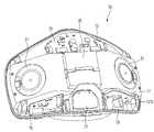
도 6은 본 발명의 실시예에 따른 마스크 장치를 구성하는 리어 바디의 전면 사시도이고, 도 7은 상기 리어 바디의 배면 사시도이다.6 is a front perspective view of a rear body constituting a mask device according to an embodiment of the present invention, and FIG. 7 is a rear perspective view of the rear body.
도 6 및 도 7을 참조하면, 본 발명의 실시예에 따른 마스크 장치(10)를 구성하는 리어 바디(13)는, 사용자의 안면을 덮는 안면 커버부(131)와, 상기 안면 커버부(131)의 가장자리에서 전방으로 절곡되는 융착부(132)를 포함한다.6 and 7, the
상세히, 상기 융착부(132)는, 상기 안면 커버부(131)의 상면 가장자리, 양 측면 가장자리, 및 하면 가장자리를 따라 연속적으로 형성된다. 그리고, 상기 안면 커버부(13)의 하면 가장자리를 따라 절곡되어 전방으로 연장되는 상기 융착부(132)의 전후 방향 폭이 가장 크다.In detail, the fused
상기 융착부(132) 중, 상기 안면 커버부(131)의 하면 가장자리에 형성되는 부분은 특별히 연장턱으로 정의될 수 있다. 상기 연장턱은, 상기 리어 바디(13)의 양 측단으로부터 중앙으로 갈수록 전후 방향 폭이 증가하는 형태로 볼록하게 라운드지는 형상을 이룬다.Among the fused
연장턱으로 정의되는 상기 융착부(132)의 중앙에는 하면 배기구(1362)가 형성되고, 상기 하면 배기구(1362)로부터 상기 리어 바디(13)의 측단부 쪽으로 이격되는 지점에 버튼홀(1321)이 형성될 수 있다. 상기 버튼홀(1321)에는 전원 버튼이 삽입된다. 상기 버튼홀(1321)의 좌측 및 우측 가장자리로부터 이격되는 지점에는 인디케이션 홀(1322)이 각각 형성된다.A
상기 전원 모듈(16)에 실장된 발광 수단으로부터 조사되는 빛은 상기 한 쌍의 인디케이션 홀(1322)을 통하여 외부로 방출된다. 상기 발광 수단은 LED 모듈을 포함한다.Light emitted from the light emitting unit mounted on the
상기 한 쌍의 인디케이션 홀(1322) 중 어느 하나를 통하여 외부로 빛이 방출되면 상기 마스크 장치(10)의 전원이 온된 상태임을 의미할 수 있다. 그리고, 상기 한 쌍의 인디케이션 홀(1322) 중 다른 하나를 통하여 방출되는 빛의 색깔에 따라 상기 배터리(20)의 잔량을 예측할 수 있다.When light is emitted to the outside through one of the pair of
상기 버튼홀(1321)로부터 상기 리어 바디(13)의 측단부 쪽으로 더 이격되는 지점에는 단자 삽입구(1323)가 형성된다. USB(Universal Serial Bus) 케이블이 상기 단자 삽입구(1323)를 관통하여 상기 전원 모듈(16)에 형성된 단자 연결부(terminal connector)에 삽입될 수 있다. 상기 USB 케이블을 통하여 상기 배터리(20)가 충전되고, 상기 USB 케이블을 통하여 전송되는 데이터에 의하여 상기 마스크 장치(10)의 버전 또는 기능이 업데이트 또는 업그레이드될 수 있다.A
상기 리어 바디(13)에는 상기 에어 클리닝 모듈(30)을 수용하기 위한 수용부(133)가 형성된다. 상기 수용부(133)는 상기 리어 바디(13)의 중심으로부터 좌측과 우측에 각각 형성되며, 상기 한 쌍의 수용부(133)는 상기 리어 바디(13)의 중심을 지나는 수직선을 기준으로 대칭된다.An accommodating part 133 for accommodating the
상기 수용부(133)는, 상기 안면 커버부(131)의 전면으로부터 전방으로 돌출됨으로써, 상기 에어 클리닝 모듈(30)을 수용하는 공간을 형성한다. 상기 수용부(133)는, 상기 에어 클리닝 모듈(30), 구체적으로 상기 팬 모듈(31)이 안착되는 안착면(1331)과, 상기 안면 커버부(131)의 측단부에서 상기 안착면(1331)의 외측 가장자리를 연결하는 체결면(1335)과, 상기 안착면(1331)의 내측 가장자리에서 상기 안면 커버부(131)의 전면을 연결하는 에어 가이드면(1334)을 포함한다.The accommodating part 133 protrudes forward from the front surface of the
또한, 상기 수용부(133)는, 상기 안착면(1331), 에어 가이드면(1334), 및 체결면(1335)의 상단들과 상기 안면 커버부(131)의 전면을 연결하는 상면(1332)을 더 포함한다. 그리고, 상기 수용부(133)는, 상기 안착면(1331), 에어 가이드면(1334), 및 체결면(1335)의 하단들과 상기 안면 커버부(131)의 전면을 연결하는 하면(1333)을 더 포함한다.In addition, the accommodating part 133 has an
상기 체결면(1335)에는 하나 또는 다수의 체결 수단, 일례로 체결 후크가 형성된다.One or more fastening means, for example fastening hooks, are formed on the
상기 안착면(1331)에는 팬 장착홀(1336)이 형성되고, 상기 상면(1332)과 상기 하면(1334)은 수평하게 연장되고, 서로 평행하게 연장될 수 있다.A
상기 체결면(1335)은 상기 리어 바디(13)의 바깥쪽을 향하여 볼록하게 라운드지되, 상기 안면 커버부(131)로부터 상기 안착면(1331)으로 갈수록 상기 리어 바디(13)의 중심을 향하여 경사지게 형성될 수 있다.The
상기 에어 가이드면(1334)은, 상기 안착면(1331)으로부터 상기 안면 커버부(131)를 향하여 볼록하게 라운드지게 연장되어, 상기 팬 모듈(31)에 의하여 흡입되는 공기가 상기 에어 가이드면(1334)을 따라 상기 토출구(101) 쪽으로 부드럽게 안내되도록 설계될 수 있다.The
다른 예로서, 상기 에어 가이드면(1334)은, 상기 안착면(1331)의 안쪽 가장자리에서 소정 곡률로 라운드지는 라운드부와, 상기 라운드부의 단부에서 상기 안면 커버부(131)를 평평하되 경사지게 연결하는 경사부로 이루어질 수 있다.As another example, the
상기 수용부(133)는, 상기 리어 바디(13)의 중심으로부터 좌측에 형성되는 좌측 수용부와, 상기 리어 바디(13)의 중심으로부터 우측에 형성되는 우측 수용부를 포함한다. 상기 좌측 수용부와 우측 수용부는 상기 리어 바디(13)의 중심으로부터 소정 간격 이격되고, 상기 좌측 수용부와 우측 수용부 사이의 공간에 상기 배터리(20)가 장착된다.The accommodating part 133 includes a left accommodating part formed on the left side from the center of the
상기 리어 바디(13)의 전면에는 배터리 장착부(138)가 형성될 수 있다. 상세히, 상기 배터리 장착부(138)는, 한 쌍의 배터리 안착 리브(1381)와, 배터리 지지 리브(1382)를 포함한다.A
상기 한 쌍의 배터리 안착 리브(1381)는, 상기 안면 커버부(131)의 전면 또는 상기 에어 가이드면(1334)의 가장자리에서 전방으로 돌출되고, 수직 방향으로 평행하게 연장된다. 상기 한 쌍의 배터리 안착 리브(1381)는 상기 배터리(20)의 배면을 지지한다.The pair of
상기 배터리 지지 리브(1382)의 일 단부는 좌측의 에어 가이드면(1334)과 우측의 에어 가이드면(1334) 중 어느 일측에서 연장되고, 타 단부는 좌측의 에어 가이드면(1334)과 우측의 에어 가이드면(1334) 중 다른 일측에 연결된다.One end of the
상기 배터리 지지 리브(1382)는 n자 형상으로 이루어져서, 상기 배터리(20)의 전면과 양 측면을 지지한다. 따라서 상기 배터리 지지 리브(1382)에 의하여 상기 배터리(20)가 상기 리어 바디(13)로부터 분리되는 현상이 방지될 수 있다.The
또한, 상기 배터리 지지 리브(1382)의 중심부는 전방으로 돌출되어 크기가 다른 배터리를 선택적으로 장착 가능하게 한다.In addition, the central portion of the
상세히, 상기 배터리 지지 리브(1382)는, 상기 한 쌍의 에어 가이드면(1334)으로부터 전방으로 연장되는 한 쌍의 연장부와, 가로 방향으로 연장되어 상기 한 쌍의 연장부를 연결하는 연결부를 포함하는 것으로 설명될 수 있다.In detail, the
그리고, 상기 연결부의 일부가 전방으로 절곡 및 연장되어, 상기 배터리 지지 리브(1382)가 제 1 배터리 지지부(1382a)와 제 2 배터리 지지부(1382b)로 이루어지는 것으로 설명될 수 있다. 상세히, 상기 제 1 배터리 지지부(1382a)는 상대적으로 폭이 넓고 두께가 얇은 배터리를 지지하는데 사용되고, 상기 제 2 배터리 지지부(1382b)는 상대적으로 폭이 좁고 두께가 두꺼운 배터리를 지지하는데 사용될 수 있다.In addition, it can be described that a portion of the connection portion is bent and extended forward so that the
상기 제 2 배터리 지지부(1382b)는, 상기 제 1 배터리 지지부(1382a)를 구성하는 연결부의 일부분이 전방으로 다수 회 절곡되어 형성되는 것으로 설명될 수 있다. 또는, 상대적으로 크기가 큰 n자 형상의 제 1 배터리 지지부(1382a)의 전면에서 상대적으로 크기가 작은 n자 형상의 제 2 배터리 지지부(1382b)가 돌출 형성되는 것으로 설명될 수 있다.The second
상기 배터리 장착부(138)의 하측에 해당하는 상기 안면 커버부(131)의 전면으로부터 배기 유로 가이드(136)가 전방으로 돌출된다. 상세히, 상기 배기 유로 가이드(136)는 상기 배터리 장착부(138)의 하측에 형성되어, 상기 배터리 장착부(138)에 장착된 배터리(20)의 하단부가 상기 배기 유로 가이드(136)의 상면에 의하여 지지된다. 그 결과, 상기 배터리(20)가 상기 배터리 장착부(138)에 끼워진 상태에서 중력에 의하여 하측으로 빠지는 현상이 방지될 수 있다.An
상기 배기 유로 가이드(136)는 대략 터널 형태의 종단면을 형성할 수 있고, 상기 배기 유로 가이드(136)의 내측에 해당하는 상기 안면 커버부(131)에는 전면 배기구(1361)가 형성될 수 있다.The
상기 전면 배기구(1361) 및 상기 하면 배기구(1362) 중 적어도 하나는, 다수의 그릴 또는 구획 리브에 의하여 다수의 작은 배기구로 분할되는 배기 그릴 형태로 이루어질 수 있다. 그리고, 상기 전면 배기구(1361)는 상기 배기 밸브(21)에 의하여 선택적으로 개폐된다.At least one of the
상기 안면 커버부(131)의 전면 중앙 상단에는 상부 마그넷 장착부(134)가 형성되고, 상기 안면 커버부(131)의 전면 하단에는 한 쌍의 하부 마그넷 장착부(135)가 형성된다.An upper
상세히, 상기 하부 마그넷 장착부(135)는 상기 배기 유로 가이드(136)의 좌측 가장자리와 우측 가장자리에 각각 형성된다. 그리고, 상기 하부 마그넷 장착부(135)에 장착되는 마그넷은, 상기 프런트 바디(12)의 배면에서 돌출되는 상기 한 쌍의 마그넷 가압 리브(126 : 도 5 참조)에 의하여 가압된다.In detail, the lower
상기 리어 바디(13)의 좌측단부와 우측 단부에는 스트랩 연결부(137)가 각각 형성된다. 상세히, 상기 스트랩 연결부(137)는, 사용자의 귀에 걸리거나 사용자의 후두부를 감싸는 스트랩 또는 밴드의 단부가 연결되는 부분이다. 상기 스트랩 연결부(137)는 상기 리어 바디(13)의 좌측단 상부와 하부, 우측단 상부와 하부에 각각 형성된다.Strap connection parts 137 are formed at left and right ends of the
한 쌍의 스트랩 중 어느 하나의 양 단부는 좌측 상단과 하단에 구비되는 스트랩 연결부(137)에 각각 연결되고, 다른 하나의 양 단부는 우측 상단과 하단에 구비되는 스트랩 연결부(137)에 각각 연결될 수 있다. 그러면, 상기 한 쌍의 스트랩은 사용자의 양 쪽 귀에 각각 걸리도록 할 수 있다.Both ends of one of the pair of straps may be respectively connected to strap connection parts 137 provided at upper and lower left ends, and both ends of the other strap may be respectively connected to strap connection parts 137 provided at upper and lower right sides. there is. Then, the pair of straps can be hung on both ears of the user.
다른 방법으로서, 한 쌍의 스트랩 중 어느 하나의 양 단부는 좌측 상단과 우측 상단에 구비되는 스트랩 연결부(137)에 각각 연결되고, 다른 하나의 양 단부는 좌측 하단과 우측 하단에 구비되는 스트랩 연결부(137)에 각각 연결될 수 있다. 그러면, 상기 한 쌍의 스트랩은 사용자의 후두부에 둘러질 수 있다.As another method, both ends of either one of the pair of straps are connected to the strap connecting parts 137 provided at the upper left and upper right ends, respectively, and both ends of the other strap are provided at the lower left and lower right strap connecting parts ( 137) can be connected to each. Then, the pair of straps can be wrapped around the back of the user's head.
상기 네 개의 스트랩 연결부(137) 각각은, 상기 리어 바디(13)의 전면에서 함몰되되, 가로 방향(리어 바디의 폭 방향)으로 연장되는 스트랩 홈(1373)과, 상기 스트랩 홈(1373)의 어느 지점에 형성되는 스트랩 홀(1374)과, 상기 스트랩 홈(1373)의 상면과 하면을 연결하는 스트랩 바(1372)와, 상기 스트랩 홀(1374)의 가장자리에 해당하는 상기 리어 바디(13)의 배면에서 연장되는 통 형상의 방수 리브(1371)를 포함한다.Each of the four strap connection parts 137 is recessed in the front surface of the
한편, 상기 리어 바디(13)의 전면에는 메인 제어 모듈 장착부(139)가 형성된다.Meanwhile, a main control
상세히, 상기 메인 제어 모듈 장착부(139)는, 상기 안면 커버부(131)의 전면에서 전방으로 돌출되는 기판 고정 후크(1391)와, 상기 메인 제어 모듈(13)의 배면을 지지하는 기판 안착 리브(1393) 및 기판 지지 리브(1392)를 포함한다.In detail, the main control
상세히, 상기 기판 고정 후크(1391)는, 상기 수용부(133)의 상측에 위치하는 한 쌍의 제 1 기판 고정 후크(1391a)와, 마주보는 상기 한 쌍의 수용부(133) 사이에 위치하는 한 쌍의 제 2 고정 후크(1391b)를 포함할 수 있다.In detail, the
상기 한 쌍의 제 1 기판 고정 후크(1391a)는, 좌측 수용부의 상면으로부터 상측으로 이격되는 지점과, 우측 수용부의 상면으로부터 상측으로 이격되는 지점에 배치될 수 있다. 상기 한 쌍의 제 1 기판 고정 후크(1391a)는 상기 메인 제어 모듈(15)의 좌측 및 우측 단부를 고정하는 기능을 한다.The pair of first
또한, 상기 한 쌍의 제 2 기판 고정 후크(1391b)는, 상기 한 쌍의 수용부(133)의 내측 상단에 해당하는 지점에 각각 위치할 수 있다. 상세히, 상기 한 쌍의 제 2 기판 고정 후크(1391b) 중 어느 하나는, 우측 수용부의 상측 모서리와 상기 안면 커버부(131)의 전면이 만나는 지점에 형성될 수 있다. 그리고, 상기 한 쌍의 제 2 기판 고정 후크(1391b) 중 다른 하나는, 좌측 수용부의 상측 모서리와 상기 안면 커버부(131)의 전면이 만나는 지점에 형성될 수 있다.In addition, the pair of second substrate fixing hooks 1391b may be located at points corresponding to inner upper ends of the pair of accommodating parts 133 . In detail, one of the pair of second substrate fixing hooks 1391b may be formed at a point where an upper edge of the right accommodating part and the front surface of the
상기 한 쌍의 제 2 기판 고정 후크(1391b)는 상기 메인 제어 모듈(15)을 구성하는 제어 기판의 하단부를 고정하는 기능을 한다.The pair of second board fixing hooks 1391b serve to fix the lower end of the control board constituting the
그리고, 상기 기판 안착 리브(1392)는 상기 한 쌍의 제 2 기판 고정 후크(1391b) 사이에 해당하는 상기 안면 커버부(131)의 전면으로부터 돌출되어, 상기 메인 제어 모듈(15)을 구성하는 제어 기판의 하단부 배면을 지지할 수 있다.In addition, the
또한, 상기 메인 제어 모듈(15)의 상단부 배면은 상기 상부 마그넷 장착부(134)의 전단부에 의하여 지지될 수 있다. 상기 메인 제어 모듈(15)은, 상기 상부 마그넷 장착부(134)와 기판 안착 리브(1393)에 의하여 상기 안면 커버부(131)로부터 이격된 상태로 놓이고, 상기 기판 고정 후크(1391)에 의하여 흔들림 없이 안정적으로 상기 리어 바디(13)에 결합되는 효과가 있다.In addition, the rear surface of the upper end of the
한편, 상기 안면 커버부(131)의 전면 상부 중앙에는 압력 센서 장착부(또는 호흡 센서 장착부)(130)가 형성될 수 있다. 상기 압력 센서 장착부(130)에 장착되는 압력 센서(후술함)는 상기 페이스 가드(14) 내측에 정의되는 호흡 공간 내부의 압력을 감지한다. 즉, 호흡 공간 내부의 압력 변화에 따라 사용자가 현재 숨을 들이쉬는 중인지 내쉬는 중인지 여부가 판단될 수 있다. 상기 압력 센서는 호흡 센서로 정의될 수도 있으며, 용어는 다르더라도 동일한 기능을 수행하는 센서로 이해되어야 함을 밝혀둔다.On the other hand, a pressure sensor mounting portion (or respiration sensor mounting portion) 130 may be formed in the front upper center of the
상기 압력 센서 장착부(130)는, 상기 리어 바디(13)의 전면에 제공되되, 상기 메인 제어 모듈(15)이 상기 메인 제어 모듈 장착부(139)에 장착되면, 상기 메인 제어 모듈(15)의 배면에 실장된 압력 센서(또는 호흡 센서)가 위치하는 지점에 위치한다. 따라서, 상기 메인 제어 모듈(15)이 상기 메인 제어 모듈 장착부(139)에 장착되면, 상기 압력 센서는 상기 압력 센서 장착부(130) 내에 수용된다. 그리고, 상기 압력 센서 장착부(130)의 전단부는 상기 메인 제어 모듈(15)의 제어 기판 배면에 밀착된다.The pressure
또한, 상기 압력 센서 장착부(130)의 바닥을 정의하는 부분은 상기 리어 바디(13)의 후방으로 돌출되고, 후방으로 돌출되는 부분의 하면에는 통공(1301)이 형성된다. 상기 통공(1301)에 의하여, 상기 리어 바디(13)의 배면과 상기 페이스 가드(14)에 의하여 정의되는 호흡 공간과 상기 압력 센서 장착부(130)의 내부 공간이 서로 연통하게 된다. 그 결과, 사용자가 숨을 내쉴 때 발생하는 공기의 일부가 상기 통공(1301)을 통하여 상기 압력 센서 장착부(130)의 내부 공간으로 흘러 들어간다. 그리고, 상기 압력 센서 장착부(130)에 수용된 상기 압력 센서에서 상기 압력 센서 장착부(130) 내부의 압력을 감지하게 된다. 그리고, 감지된 압력값은 상기 메인 제어 모듈(15)의 마이콤(후술함)으로 전송되어, 사용자의 호흡 상태가 판단된다.In addition, a portion defining the bottom of the pressure
한편, 상기 상부 마그넷 장착부(134)의 직후면에 해당하는 상기 리어 바디(13)의 배면과, 상기 한 쌍의 하부 마그넷 장착부(135)의 직후면에 해당하는 상기 리어 바디(13)의 배면에는 마그넷 장착홈(1314)이 각각 형성된다.Meanwhile, on the rear surface of the
상기 마그넷 장착홈(1314)은, 상기 상부 마그넷 장착부(134)의 직후면에 형성되는 제 1 마그넷 장착홈(1311)과, 상기 하부 마그넷 장착부(134)의 직후면에 형성되는 제 2 마그넷 장착홈(1312) 및 제 3 마그넷 장착홈(1313)을 포함한다.The
상기 제 1 내지 제 3 마그넷 장착홈(1311 ~ 1313)에는 상기 페이스 가드(14)에 장착된 세 개의 마그넷이 각각 자기력에 의하여 부착된다. 그리고, 사용자가 상기 자기력보다 큰 힘으로 상기 페이스 가드(14)를 잡아당기면, 상기 페이스 가드(14)는 상기 리어 바디(13)로부터 쉽게 분리 가능하다.The three magnets mounted on the
한편, 이미 설명한 바와 같이, 상기 수용부(133)를 구성하는 안착면(1331)에는 팬 장착홀(1336)이 형성될 수 있다. 그리고, 상기 팬 장착홀(1336)로부터 상기 안착면(1331)의 외측 가장자리 쪽으로 이격되는 지점에는 하나 또는 다수의 유동 가이드 체결홀(1331a)이 형성된다. 상기 유동 가이드(32)는 상기 유동 가이드 체결홀(1331a)을 관통하는 체결부재에 의하여 상기 수용부(133)에 고정된다.Meanwhile, as described above, a
그리고, 상기 수용부(133)를 구성하는 체결면(1335)에는 유동 가이드 후크(1339)와 필터 후크(1338)가 각각 전후 방향으로 이격되어 형성된다. 상기 필터 후크(1338)보다 상기 유동 가이드 후크(1339)가 상기 안착면(1331)에 더 가까이 위치한다.In addition, the
그리고, 상기 필터 후크(1338)의 후방에 해당하는 상기 리어 바디(13)의 배면 측단에는 파지홈(1337)이 형성된다. 상세히, 상기 융착부(132)와, 상기 체결면(1335)이 만나는 지점에 상기 파지홈(1337)이 형성되는 것으로 설명될 수 있다.In addition, a
도 8은 본 발명의 실시예에 따른 마스크 장치의 횡단면도이고, 도 9는 상기 마스크 장치의 종단면도이다.8 is a cross-sectional view of a mask device according to an embodiment of the present invention, and FIG. 9 is a longitudinal cross-sectional view of the mask device.
도 8 및 도 9를 참조하면, 사용자가 전원 버튼을 눌러서 상기 팬 모듈(31)을 작동시키면, 상기 마스크 장치(10)의 배면 좌측과 우측에 형성된 흡입 그릴(343)(또는 흡입구)을 통하여 외부 공기가 상기 마스크 장치(10) 내부로 유입된다.8 and 9, when the user presses the power button to operate the
상기 흡입 그릴(343)을 통하여 유입되는 외부 공기는 상기 필터(33)를 통과하면서 정화된다. 그리고, 상기 필터(33)를 통과한 공기는 상기 팬 모듈(31)의 축 방향으로 흡입된 후 반경 방향으로 토출된다.External air introduced through the
상기 팬 모듈(31)의 전면은, 도 8에 보이는 바와 같이, 상기 안착면(1331)에 안착되고, 상기 팬 모듈(31)의 배면은 개방된다. 그리고, 개방된 상기 팬 모듈(31)의 배면은 상기 유동 가이드(32)에 의하여 차폐되고, 상기 유동 가이드(32)에는 상기 팬모듈(31)의 흡입구로 기능하는 연통홀이 형성된다. 상기 필터(33)를 통과한 공기는 상기 연통홀을 통과하여 상기 팬 내부로 유입된다.As shown in FIG. 8 , the front surface of the
또한, 상기 유동 가이드(32)의 측면과, 상기 에어 가이드면(1334) 사이에 에어 덕트(102)가 정의된다. 그리고, 상기 에어 덕트(102)의 입구는 상기 팬 모듈(31)의 출구(또는 토출구)와 연통하고, 상기 에어 덕트(102)의 출구는 상기 토출구(101)와 연통한다.In addition, an
그리고, 상기 토출구(101)는, 상기 페이스 가드(14)와 상기 리어 바디(13)의 배면에 의하여 정의되는 상기 호흡 공간 내에 위치한다. 따라서, 상기 팬 모듈(31)에 의하여 흡입되는 외부 공기는 상기 호흡 공간으로 토출되어, 사용자가 흡입 가능하게 한다.And, the
그리고, 상기 에어 가이드 면(1334)은 상기 팬 모듈(31)의 출구로부터 상기 토출구(101)를 향하여 부드럽게 라운드지게 형성되어, 상기 팬 모듈(31)의 반경 방향으로 토출되는 공기가 상기 토출구(101)를 향하여 흐르는 과정에서 유동 방향의 급격한 전환이 없다.Also, the
상세히, 원심팬의 경우, 축방향으로 흡입되어 반경 방향으로 토출되도록 하는 것은 원추형(cone) 또는 절단된 원추형(truncated cone) 허브의 형상에서 기인한다. 즉, 원심팬의 축방향으로 흡입되는 공기는, 상기 허브의 라운드진 면을 따라 부드럽게 유동 방향이 90도로 전환된다.In detail, in the case of a centrifugal fan, the intake in the axial direction and the discharge in the radial direction result from the shape of the hub, which is a cone or a truncated cone. That is, the flow direction of the air sucked in in the axial direction of the centrifugal fan is smoothly changed at 90 degrees along the rounded surface of the hub.
여기서, 상기 팬 모듈(31)을 구성하는 허브의 라운드지는 방향과, 상기 에어 가이드면(1334)의 라운드지는 방향이 같기 때문에, 팬 모듈(31)로 흡입되는 공기는 한 방향으로만 부드럽게 유동 전환을 하게 된다.Here, since the rounding direction of the hub constituting the
만일, 상기 흡입 그릴(343)이 상기 프런트 바디(12)에 형성된다면, 상기 팬 모듈(31)의 흡입구는 상기 프런트 바디(12)를 향하게 되고, 그 결과, 팬 모듈을 구성하는 허브의 라운드지는 방향과 상기 에어 가이드면(1334)의 라운드지는 방향이 반대가 된다. 그 결과, 상기 팬 모듈(31)로부터 토출되는 공기는 상기 에어 덕트(102)의 입구에 해당하는 상기 에어 가이드면(1334)의 시작 부분에 부딪혀서 유동 저항 및 유동 소음을 발생시킨다.If the
즉, 상기 팬 모듈(31)의 축방향으로 흡입되는 공기는 실질적으로 S 자 형태의 유동을 형성하게 되어, C 자 또는 n 자 형태의 유동을 형성하는 본 발명 구조에 비하여 유동 손실이 크게 된다.That is, the air sucked in the axial direction of the
한편, 사용자가 내쉴 때 사용자의 입과 코를 통하여 배출되는 공기는 상기 호흡 공간에 모이게 된다. 그리고, 상기 호흡 공간에 모인 공기의 미세한 일부는 상기 통공(1301)을 통하여 상기 압력 센서 장착부(130) 내부로 유입된다.Meanwhile, when the user exhales, air discharged through the user's mouth and nose is collected in the breathing space. Also, a minute portion of the air collected in the breathing space is introduced into the pressure
그리고, 상기 호흡 공간에 모인 공기의 대부분은 하강하여 상기 전면 배기구(1361) 및 상기 하면 배기구(1362)를 통하여 외부로 배출된다. 여기서, 사용자가 숨을 내쉴 때 발생하는 공기의 압력에 의하여 상기 배기 밸브(20)가 전방으로 휘어지면서 상기 전면 배기구(1361)가 개방된다. 그리고, 사용자가 숨을 들이마실 때는 상기 호흡 공간 내부의 압력이 대기압보다 낮아지면서 상기 배기 밸브(20)가 원위치로 되돌아와서 상기 전면 배기구(1361)를 차폐하게 된다.And, most of the air collected in the breathing space descends and is discharged to the outside through the
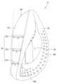
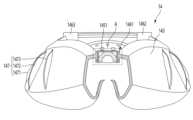
도 10은 본 발명의 실시예에 따른 페이스 가드의 정면도이고, 도 11은 상기 페이스 가드의 배면도이고, 도 12는 상기 페이스 가드의 측면도이고, 도 13은 도 11의 13-13을 따라 절개되는 페이스 가드의 부분 단면도이다.Figure 10 is a front view of a face guard according to an embodiment of the present invention, Figure 11 is a rear view of the face guard, Figure 12 is a side view of the face guard, Figure 13 is cut along 13-13 of Figure 11 A partial sectional view of the face guard.
도 10 내지 도 13을 참조하면, 본 발명의 실시 예에 따른 마스크 장치(10)를 구성하는 상기 페이스 가드(14)는, 상기 마스크 바디(11)의 배면에 고정 또는 분리 가능하게 결합되고 사용자의 안면에 밀착될 수 있다.10 to 13, the
즉, 상기 페이스 가드(14)의 전면부는 상기 리어 바디(13)의 배면에 밀착되고, 상기 페이스 가드(14)의 배면부는 사용자의 안면에 밀착될 수 있다.That is, the front part of the
상기 페이스 가드(14)는 일정 두께를 가지며 중심부가 비어있는 물방울 형상 또는 도넛 형상으로 형성될 수 있다. 상기 페이스 가드(14)는 중심 부분이 전면으로부터 배면까지 관통되어 내측에 사용자의 코 또는 입이 수용되는 수용공간(144)을 마련할 수 있다.The
상기 페이스 가드(14)는 하부에서 상부로 갈수록 좌우방향 폭이 슬림해지는 형태로 형성될 수 있다. 상기 수용공간(144) 또한 하부에서 상부로 갈수록 점점 폭이 좁아지게 형성된다. 이에 따라, 상기 수용공간(144)의 하부 공간에는 사용자의 입이 수용되고, 상기 수용공간(144)의 상부 공간에는 사용자의 코가 수용될 수 있다. 사용자가 상기 마스크 장치(10)를 착용하면, 사용자의 코가 상기 페이스 가드(14)의 상부에 고정되어 밀착될 수 있다.The
상기 페이스 가드(14)는 신축성을 가지는 실리콘 또는 고무 소재로 성형될 수 있으며, 사용자의 안면에 밀착되어 상기 페이스 가드(40)의 내측에 호흡 공간을 형성할 수 있다.The
상세히, 상기 페이스 가드(14)는, 상기 리어 바디(13)의 배면과 마주하는 결합부(141)와, 사용자의 안면에 밀착되는 밀착부(142)와, 상기 결합부(141)와 상기 밀착부(142)를 연결하며 전후 방향으로 소정의 폭을 가지는 연결부(143)를 포함할 수 있다. 상기 결합부(141)와 밀착부(142) 및 연결부(143)는 일체로 성형될 수 있다.In detail, the
다른 한편으로는, 상기 페이스 가드(14)는 상기 리어 바디(13)의 배면에 밀착되는 전면부와, 사용자의 안면에 밀착되는 배면부와, 상기 전면부와 상기 배면부를 연결하며 전후 방향으로 소정의 폭을 가지는 측면부를 포함하는 것으로 설명될 수 있다.On the other hand, the
상기 결합부(141)는, 상기 페이스 가드(14)의 전단부 가장자리를 따라 일정한 폭을 가지며 둘러지도록 형성될 수 있다. 상기 결합부(141)는 폐루프를 형성하는 링 형상으로 형성될 수 있다.The
상기 결합부(141)에는, 상기 리어 바디(13)의 전면에 장착되는 마그넷과 인력을 작용하는 자성체(145)가 장착되는 자성체 장착부(146)가 구비된다.The
상기 자성체 장착부(146)는, 상기 결합부(141)로부터 전방을 향해 돌출되며, 내측에 상기 자성체(145)가 삽입되어 장착될 수 있다. 상기 자성체 장착부(146)는 복수 개로 형성될 수 있다.The magnetic body mounting portion 146 protrudes forward from the
상세히, 상기 자성체 장착부(146)는, 상기 결합부(141)의 상부에 배치되는 제 1 자성체 장착부(1461)와, 상기 결합부(141)의 하부에 배치되되 양측으로 서로 이격되는 제 2 자성체 장착부(1462) 및 제 3 자성체 장착부(1463)를 포함한다.In detail, the magnetic body mounting portion 146 includes a first magnetic
이때, 상기 제 1 자성체 장착부(1461)와 제 2 자성체 장착부(1462) 및 제 3 자성체 장착부(1463)는 동일한 형상을 가질 수 있다.In this case, the first magnetic
다만, 본 실시 예에서는 상기 제 1 자성체 장착부(1461)는 가로 방향으로 길게 배치되고, 상기 제 2 자성체 장착부(1462) 및 제 3 자성체 장착부(1463)는 세로 방향으로 길게 배치될 수 있다. 즉, 상기 제 1 내지 제 3 자성체 장착부(1461 ~ 1463)는 동일한 형태 또는 구조를 가지므로, 이하에서는 상기 제 1 자성체 장착부(1461)를 대표적으로 설명하도록 한다.However, in this embodiment, the first magnetic
상기 제 1 자성체 장착부(1461)는 상기 결합부(141)의 상단 중심에 배치되고, 상기 제 2 자성체 장착부(1462) 및 제 3 자성체 장착부(1463)는 상기 결합부(141)의 하단 중심으로부터 각각 양측으로 이격된 지점에 배치될 수 있다.The first magnetic
또한, 상기 제 1 자성체 장착부(1461)의 내측에는 제 1 자성체(1451)가 장착되고, 상기 제 2 자성체 장착부(1461)의 내측에는 제 2 자성체(1452)가 장착되고, 상기 제 3 자성체 장착부(1463)의 내측에는 제 3 자성체(1453)가 장착된다.In addition, the first
이러한 구성에 의하면, 상기 제 1 내지 제 3 자성체(1451 ~ 1453)를 각각 상기 제 1 내지 제 3 마그넷 장착홈(1311 ~ 1313)에 접근시키는 것만으로도, 상기 페이스 가드(14)를 상기 리어 바디(13)의 배면에 쉽게 고정시킬 수 있는 장점이 있다.According to this configuration, simply by bringing the first to third
특히, 본 실시예에 따르면, 상기 페이스 가드(14)의 상부에는 하나의 자성체(1451)가 존재하고, 상기 페이스 가드(14)의 하부에는 두 개의 자성체(1452,1453)가 존재하므로, 상기 페이스 가드(14)의 상부에 위치된 자성체(1451)를 상기 제 1 마그넷 장착홈(1311)에 먼저 결합시킴으로써, 나머지 두 개의 자성체(1452,1453)의 위치가 자연스럽게 상기 제 2 및 제 3 마그넷 장착홈(1312,1313)에 위치되는 것이 유도될 수 있다.In particular, according to this embodiment, since one
따라서, 3개의 자성체(1451,1452,1453)를 각각 3개의 마그넷 장착홈(1311,1312,1313)에 모두 맞출 필요가 없어지며 오결합될 일이 없어지므로, 페이스 가드(14)의 장착이 쉽고 편해지는 장점이 있다.Therefore, since there is no need to align the three
그리고, 3개의 자성체(1451,1452,1453)가 각각 자기력에 의해 부착된 상태에서, 사용자가 상기 자기력보다 큰 힘으로 상기 페이스 가드(14)를 잡아당기면, 상기 페이스 가드(14)는 상기 리어 바디(13)로부터 쉽게 분리 가능한 장점이 있다.And, in a state where the three
한편, 상기 페이스 가드(14)에는 외면으로부터 돌출되어, 상기 연결부(143)의 적어도 일부를 상기 필터 커버(342)로부터 이격된 상태로 유지하는 이격 돌기(147)가 형성된다.Meanwhile, a
상기 이격 돌기(147)는, 상기 연결부(143)의 외면으로부터 하나 또는 다수 개가 형성될 수 있다. 상기 이격 돌기(147)는 볼록하게 형성되거나 또는 라운드지게 형성될 수 있다. 상기 이격 돌기(147)는 상기 필터 커버(343)의 영역 내에 배치될 수 있다.One or more of the spaced
또한, 상기 이격 돌기(147)는 상기 연결부(143)의 외면에서 전후 방향으로 길게 형성될 수 있다. 상기 이격 돌기(147)는 상기 이격 돌기(147)가 위치되는 상기 연결부(143)의 폭(전후 방향) 길이에 대응하는 길이로 형성될 수 있다.In addition, the
상기 이격 돌기(147)는 다수 개가 이격되어 형성될 수 있다. 다수 개의 이격 돌기(147)는 상기 연결부(143)의 좌측면 및 우측면에 각각 형성될 수 있다. 다수 개의 이격 돌기(147)는 상기 페이스 가드(14)의 중심을 지나는 수직선을 기준으로 좌우 대칭되게 배치될 수 있다.A plurality of spaced
상세히, 상기 이격 돌기(147)는, 상기 연결부(143)의 좌측면의 하부 지점에 형성되는 제 1 돌기(1471)와, 상기 제 1 돌기(1471)의 상측에 형성되는 제 2 돌기(1472)와, 상기 제 2 돌기(1472)의 상측에 형성되는 제 3 돌기(1473)를 포함할 수 있다.In detail, the spaced
상기 제 1 내지 제 3 돌기(1471 ~ 1473)는, 상하 방향으로 서로 이격되게 배치될 수 있다. 상기 제 1 내지 제 3 돌기(1471 ~ 1473)는 서로 수평하게 배치될 수 있다.The first to
또한, 상기 제 1 내지 제 3 돌기(1471 ~ 1473)는, 상기 연결부(143)의 측면 상에서 전후 방향으로 길게 연장될 수 있다. 이때, 상기 제 1 내지 제 3 돌기(1471 ~ 1473)는, 상기 연결부(143)의 폭(전후 방향) 길이에 대응하는 길이로 형성될 수 있다.In addition, the first to
도 12에 도시된 바와 같이, 상기 연결부(143)는 하부에서 상부로 갈수록, 전후 방향 폭이 증가되는 형태로 형성되고, 이에 따라 상기 연결부(143)의 상부에 위치된 제 3 돌기(1473)는, 상기 연결부(143)의 하부에 위치된 제 1 돌기(1471) 보다 길게 형성될 수 있다.As shown in FIG. 12, the
또한, 상기 제 1 내지 제 3 돌기(1471 ~ 1473)는, 상기 필터 커버(342)의 영역 내에 배치될 수 있다. 이러한 이유는, 사용자가 마스크 장치(10)를 착용할 때, 상기 페이스 가드(14)가 눌리면서 상기 페이스 가드(14)의 부분이 상기 흡입구, 즉 상기 흡입 그릴(343)을 덮는 것을 방지하기 위함이다.Also, the first to
즉, 상기 페이스 가드(14)가 외력에 의해 눌리더라도, 상기 제 1 내지 3 돌기(1471 ~ 1473)가 상기 페이스 가드(14)를 상기 필터 커버(342)로부터 이격된 상태로 유지시킬 수 있다.That is, even if the
본 실시 예에서, 상기 제 1 돌기(1471)는, 상기 필터 커버(342)의 하단부에 해당하는 지점에 위치되고, 상기 제 2 돌기(1472)는, 상기 필터 커버(342)의 중심부에 해당하는 지점에 위치되고, 상기 제 3 돌기(1473)는, 상기 필터 커버(342)의 상단부에 해당하는 지점에 위치될 수 있다.In this embodiment, the
상기 페이스 가드(14)에는, 사용자의 안면에 밀착되는 부분에 환기를 위한 통공(1481,1482)이 형성될 수 있다. 상기 통공(1481,1482)은 상기 밀착부(142)의 가장자리 둘레를 따라 다수 개가 형성될 수 있다. 상기 통공(1481,1482)은 원형 또는 비원형의 단면을 가질 수 있다.In the
사용자가 상기 마스크 장치(10)를 착용하면, 상기 페이스 가드(14)의 밀착부(142)는 사용자의 안면에 밀착되어 고정된다. 이때 상기 마스크 장치(10)를 장시간 착용할 경우, 사용자의 안면에는 땀 또는 오염물질이 쌓일 수 있다. 따라서, 상기 페이스 가드(14)의 밀착부(142)에 다수의 통공(1481,1482)을 형성함으로써 사용자의 안면을 환기시킬 수 있다.When the user wears the
이하에서는 리어 바디에 페이스 가드가 결합되는 구조에 대해 도면을 참조하여 상세히 설명하도록 한다.Hereinafter, a structure in which the face guard is coupled to the rear body will be described in detail with reference to the drawings.
도 14는 도 13의 "A" 를 확대하여 도시한 도면이고, 도 15는 본 발명의 실시예에 따른 자성체의 사시도이고, 도 16은 상기 자성체의 측면도이고, 도 17은 상기 자성체가 결합된 자성체 장착부의 종단면도이다.14 is an enlarged view of “A” in FIG. 13, FIG. 15 is a perspective view of a magnetic body according to an embodiment of the present invention, FIG. 16 is a side view of the magnetic body, and FIG. 17 is a magnetic body to which the magnetic body is coupled. This is a cross-sectional view of the mounting part.
도 14 내지 도 17을 참조하면, 이미 설명된 바와 같이, 상기 페이스 가드(14)의 각각의 자성체 장착부(1461 ~ 1463)에는, 자성체(1451 ~ 1453)가 분리 가능하게 삽입될 수 있다.Referring to FIGS. 14 to 17 , as described above,
각각의 자성체 장착부(1461 ~ 1463)와 각각의 자성체(1451 ~ 1453)는 서로 동일한 형태 또는 구조를 가지므로, 이하에서는 제 1 자성체 장착부(1461)와, 제 1 자성체(1451)를 대표적으로 설명하도록 한다.Since each of the magnetic
상기 제 1 자성체 장착부(1461)는, 상기 결합부(141)의 외면에서 전방으로 돌출되는 장착부 바디(1461a)와, 상기 장착부 바디(1461a)의 내측에 제공되는 삽입 가이드 리브(1461b)와, 상기 장착부 바디(1461a)와 상기 삽입 가이드 리브(1461b)의 사이에 형성되는 삽입홀(1461c)을 포함한다.The first magnetic
상기 장착부 바디(1461a)는, 상기 결합부(141)의 상부 중심 지점에서 중공 형태로 돌출될 수 있다. 상기 장착부 바디(1461a)는 상기 제 1 자성체(1451)가 내측으로 삽입될 수 있는 형상으로 형성될 수 있다. 일례로, 상기 장착부 바디(1461a)는 사각 형상을 가질 수 있고, 전면 및 배면이 개구된 형상을 가질 수 있다.The mounting
상기 삽입 가이드 리브(1461b)는, 상기 제 1 자성체(1451)의 삽입 위치를 안내하면서, 상기 제 1 자성체(1451)가 흔들림 없이 안정적으로 지지하는 기능을 한다. 상기 삽입 가이드 리브(1461b)에 의해 삽입 위치가 안내된 제 1 자성체(1451)는 상기 삽입홀(1461c)에 삽입될 수 있다.The
상세히, 상기 삽입 가이드 리브(1461b)는, U자 형상으로 이루어져서, 상기 장착부 바디(1461a)의 내측 중심에 배치된다. 이에 따라, 상기 장착부 바디(1461a)의 내주면과 상기 삽입 가이드 리브(1461b)의 좌측 단부 사이에는, 제 1 삽입홀(1461c)이 형성되고, 상기 장착부 바디(1461a)의 내주면과 상기 삽입 가이드 리브(1461b)의 우측 단부 사이에는, 제 2 삽입홀(1461c)이 형성된다.In detail, the
즉, 상기 삽입홀(1461c)은 복수 개로 제공되며, 상기 복수 개의 삽입홀(1461c)에 상기 제 1 자성체(1451)의 양측 단부가 삽입될 수 있다. 상기 제 1 자성체(1451)가 상기 장착부 바디(1461a)에 결합되면, 상기 제 1 자성체(1451)의 고정 후크(1471d)가 상기 삽입홀(1461c)에 걸림 고정될 수 있다.That is, a plurality of
한편, 상기 제 1 자성체(1451)는 자성을 띤 물질로 형성되며, 일례로 철 또는 스테인리스 스틸로 성형될 수 있다. 상기 제 1 자성체(1451)는 U자 또는 "ㄷ" 형상으로 형성될 수 있다.Meanwhile, the first
상세히, 상기 제 1 자성체(1451)는, 몸체를 형성하는 자성 몸체(1451a)와, 상기 자성 몸체(1451a)의 양단으로부터 각각 후방으로 연장되어, 상기 복수의 삽입홀(1461c)에 삽입되는 고정 후크(1451d)를 포함한다.In detail, the first
상기 자성 몸체(1451a)는 사각 플레이트 형상으로 형성될 수 있다. 일례로, 상기 자성 몸체(1451a)는 전후 방향으로의 두께를 가지며, 좌우 방향으로 길이가 긴 사각 플레이트로 형성될 수 있다. 이때 상기 고정 후크(1451d)는 상기 자성 몸체(1451a)의 좌측 및 우측 단부에서 각각 후방으로 연장되어 형성될 수 있다.The
구체적으로, 상기 고정 후크(1451d)는, 상기 자성 몸체(1451a)의 양 단부 중앙에서 후방으로 소정 길이로 연장되는 연장부(1451b)와, 상기 연장부(1451b)의 단부에서 후크 형상으로 형성되는 후크부(1451c)를 포함한다. 상기 후크부(1451c)는 상기 연장부(1451b)의 단부에서 상하 방향으로 반경이 커지도록 형성될 수 있다.Specifically, the fixing
이때, 상기 후크부(1451c)의 상하 방향의 높이(H3)는, 상기 자성 몸체(1451a)의 상하 방향의 높이(H1) 보다는 작고, 상기 연장부(1451b)의 상하 방향의 높이(H2) 보다는 크게 형성된다.At this time, the height H3 of the
또한, 상기 연장부(1451b)의 상하 방향의 높이(H2)는, 상기 장착부 바디(1461a)에 형성된 삽입 슬릿(1461d)의 상하 방향의 높이(H4) 보다 약간 작게 형성된다. 그리고 상기 후크부(1451c)의 상하 방향의 높이(H3)는, 상기 삽입 슬릿(1461d)의 상하 방향 높이(H4) 보다 크게 형성되고, 상기 장착부 바디(1461a)의 삽입홀(1461c)의 상하 방향의 높이(H5) 보다 작게 형성된다.In addition, the vertical height H2 of the
여기서, 상기 자성체 장착부(1461)는 신축성을 가지는 실리콘 또는 고무 소재로 성형되므로, 상기 고정 후크(1451d)가 상기 장착부 바디(1461a)의 삽입홀(1461c)에 억지 끼움 방식으로 삽입될 수 있다.Here, since the magnetic mounting
그러면, 도 17에 도시된 바와 같이, 상기 후크부(1451c)가 상기 삽입홀(1461c) 내에 수용된 상태에서, 상기 삽입 슬릿(1461d)을 통해 외부로 탈거되는 것이 방지된다.Then, as shown in FIG. 17 , while the
도 18은 상기 리어 바디의 마그넷 장착부와 상기 페이스 가드의 자성체 장착부가 결합된 모습을 보여주는 횡단면도이다.18 is a cross-sectional view showing a state in which the magnet mounting portion of the rear body and the magnetic body mounting portion of the face guard are coupled.
이미 설명된 바와 같이, 상기 리어 바디(13)의 전면에는 상부 마그넷 장착부(134)와 한 쌍의 하부 마그넷 장착부(135)가 형성되고, 상기 상부 마그넷 장착부(134)의 직후면에 해당하는 상기 리어 바디(13)의 배면과, 상기 한 쌍의 하부 마그넷 장착부(135)의 직후면에 해당하는 상기 리어 바디(13)의 배면에는 마그넷 장착홈(1314)이 각각 형성된다.As already described, an upper
상기 마그넷 장착홈(1314)은, 상기 상부 마그넷 장착부(134)의 직후면에 형성되는 제 1 마그넷 장착홈(1311)과, 상기 하부 마그넷 장착부(134)의 직후면에 형성되는 제 2 마그넷 장착홈(1312) 및 제 3 마그넷 장착홈(1313)을 포함한다.The
상기 제 1 내지 제 3 마그넷 장착홈(1311 ~ 1313)에는, 상기 페이스 가드(14)에 장착된 세 개의 자성체(1451 ~ 1453)가 각각 자기력에 의하여 부착된다. 그리고, 사용자가 상기 자기력보다 큰 힘으로 상기 페이스 가드(14)를 잡아당기면, 상기 페이스 가드(14)는 상기 리어 바디(13)로부터 쉽게 분리 가능하다.Three
한편, 상기 상부 마그넷 장착부(134)와, 상기 한 쌍의 마그넷 장착부(135)는 그 위치만 다를 뿐 서로 동일한 형태 또는 구조를 가지므로, 이하에서는 상기 상부 마그넷 장착부(134)에 상기 제 1 자성체 장착부(1461)가 결합되는 방법에 대해 대표적으로 설명하도록 한다.On the other hand, since the upper
도 18을 참조하면, 상기 상부 마그넷 장착부(134)는, 마그넷(25)이 안착되는 안착 공간(1343)을 형성하는 마그넷 장착부 몸체(1341)를 포함한다.Referring to FIG. 18 , the upper
상기 마그넷 장착부 몸체(1341)는, 상기 리어 바디(13)의 전면에서 전방으로 돌출되며, 상기 안착 공간(1343)을 형성하기 위하여 전면 일부가 후방으로 함몰된 형태를 가질 수 있다.The
또한, 상기 마그넷 장착부 몸체(1341)의 전면 양측에는, 상기 안착 공간(1343)에 삽입된 마그넷(25)의 양 단을 잡아주기 위한 한 쌍의 제 1 가이드 리브(1342)가 형성될 수 있다. 상기 한 쌍의 제 1 가이드 리브(1342)는, 상기 안착 공간(1343)의 가장자리에 해당하는 상기 마그넷 장착부 몸체(1341)의 전면에서 전방으로 돌출될 수 있다.In addition, a pair of
상기 한 쌍의 제 1 가이드 리브(1342)의 구조에 의해서, 상기 마그넷(25)이 상기 안착 공간(1343)에 깊게 삽입되고 안정적으로 지지될 수 있다.Due to the structure of the pair of
또한, 상기 마그넷 장착부 몸체(1341)의 배면 양측에는, 상기 마그넷 장착홈(1314)에 삽입된 제 1 자성체 장착부(1461)의 양 단을 잡아주기 위한 한 쌍의 제 2 가이드 리브(1344)가 형성될 수 있다. 상기 한 쌍의 제 2 가이드 리브(1344)는, 상기 마그넷 장착홈(1314)의 가장자리에 해당하는 상기 마그넷 장착부 몸체(1341)의 배면에서 후방으로 돌출될 수 있다.In addition, a pair of
상기 한 쌍의 제 2 가이드 리브(1344)의 구조에 의해서, 상기 제 1 자성체 장착부(1461)가 상기 마그넷 장착홈(1314)에 깊게 삽입되고 안정적으로 지지될 수 있다.Due to the structure of the pair of
상기 제 1 자성체 장착부(1461)가 상기 마그넷 장착홈(1314)에 삽입되면, 상기 제 1 자성체(1451)와 상기 마그넷(25)은 마주하게 되고, 이들 사이의 거리가 가까워짐에 따라 자력에 의해서 상기 제 1 자성체 장착부(1461)와, 상기 상부 마그넷 장착부(134)가 결합될 수 있다.When the first magnetic
따라서, 상기 리어 바디(13)에 상기 페이스 가드(14)를 탈부착하는 것이 간편해지고, 상기 페이스 가드(14)가 상기 리어 바디(13)로부터 쉽게 분리되는 것이 방지되는 장점이 있다.Therefore, it is easy to attach and detach the
Claims (11)
Translated fromKorean상기 리어 바디의 배면에서 자력에 의해 결합되어 사용자의 안면에 밀착되고, 내측에 호흡 공간이 형성되는 페이스 가드; 및
상기 리어 바디에 장착되어, 상기 흡입구로 유입되는 외부 공기를 정화하여 상기 호흡 공간으로 공급하는 에어 클리닝 모듈을 포함하고,
상기 페이스 가드는,
상기 리어 바디의 배면과 마주하며, 자성체가 구비되는 결합부와,
사용자의 안면에 접촉하는 밀착부와,
상기 결합부와 상기 밀착부를 연결하여, 전후 방향으로 소정의 폭을 가지도록 형성된 연결부를 포함하고,
상기 자성체는,
상기 결합부의 전면 상단 중심에 배치되는 제 1 자성체와,
상기 결합부의 전면 하단 중심을 기준으로 각각 양측으로 이격되게 배치되는 제 2 자성체 및 제 3 자성체를 포함하고,
상기 흡입구는, 상기 페이스 가드의 외측에 해당하는 상기 리어 바디의 배면에 형성되고,
상기 토출구는, 상기 페이스 가드의 내측에 해당하는 상기 리어 바디의 배면에 형성되고,
상기 흡입구를 통해 유입된 공기는, 상기 리어 바디의 내부를 통과한 후 상기 토출구를 통해 상기 호흡 공간으로 유동하는 마스크 장치.a mask body including a rear body and a front body coupled to a front surface of the rear body, and having a suction port and a discharge port formed therein;
a face guard coupled by a magnetic force on the rear surface of the rear body to be in close contact with the user's face and having a breathing space formed therein; and
an air cleaning module mounted on the rear body to purify external air flowing into the intake and supply it to the breathing space;
The face guard,
A coupling portion facing the rear surface of the rear body and provided with a magnetic material;
A contact part in contact with the user's face;
A connection portion formed to connect the coupling portion and the close contact portion to have a predetermined width in the front-back direction;
The magnetic body,
A first magnetic body disposed at the center of the top of the front surface of the coupling unit;
A second magnetic body and a third magnetic body disposed to be spaced apart on both sides based on the center of the lower front surface of the coupling part,
The inlet is formed on a rear surface of the rear body corresponding to an outside of the face guard,
The discharge port is formed on the rear surface of the rear body corresponding to the inside of the face guard,
The mask device according to claim 1 , wherein the air introduced through the inlet passes through the inside of the rear body and then flows into the breathing space through the outlet.
상기 제 1 자성체는, 상기 에어 클리닝 모듈의 상측에 해당하는 상기 페이스 가드의 부분에 위치되고,
상기 제 2, 3 자성체는, 상기 에어 클리닝 모듈의 하측에 해당하는 상기 페이스 가드의 부분에 위치되는 마스크 장치.According to claim 1,
The first magnetic material is located on a portion of the face guard corresponding to an upper side of the air cleaning module,
The second and third magnetic materials are located in a portion of the face guard corresponding to the lower side of the air cleaning module.
상기 제 1 자성체는, 상기 토출구의 상측에 해당하는 상기 페이스 가드의 부분에 위치되고,
상기 제 2, 3 자성체는, 상기 토출구의 하측에 해당하는 상기 페이스 가드의 부분에 위치되는 마스크 장치.According to claim 1,
The first magnetic body is located in a portion of the face guard corresponding to the upper side of the discharge port,
The second and third magnetic materials are located in a portion of the face guard corresponding to the lower side of the discharge port.
상기 제 1 내지 제 3 자성체는, 상기 페이스 가드에 구비된 다수의 자성체 장착부의 내측에 각각 삽입되는 마스크 장치.According to claim 1,
The first to third magnetic materials are each inserted inside a plurality of magnetic material mounting parts provided in the face guard.
상기 다수의 자성체 장착부는, 상기 결합부의 전면에서 각각 돌출되어 형성되고, 상기 리어 바디의 배면에 부착되는 마스크 장치.According to claim 5,
The plurality of magnetic body mounting parts are formed to protrude from the front surface of the coupling part, respectively, and are attached to the rear surface of the rear body.
상기 리어 바디의 전면에는, 마그넷이 장착되는 마그넷 장착부가 돌출되어 형성되고,
상기 마그넷 장착부의 직후면에 해당하는 상기 리어 바디의 배면에는, 상기 자성체 장착부가 부착되기 위한 마그넷 장착홈이 형성되는 마스크 장치.According to claim 6,
A magnet mounting portion to which a magnet is mounted protrudes from the front surface of the rear body,
The mask device of claim 1 , wherein a magnet mounting groove for attaching the magnetic body mounting unit is formed on a rear surface of the rear body corresponding to a rear surface of the magnet mounting unit.
상기 자성체 장착부는,
상기 결합부의 외면에서 전방으로 돌출되는 장착부 바디와,
상기 장착부 바디의 내측에 형성되는 삽입 가이드 리브를 포함하고,
상기 자성체는, 상기 장착부 바디와 상기 삽입 가이드 리브의 사이에 형성된 삽입홀을 통하여, 상기 장착부 바디의 내측에 삽입되는 마스크 장치.According to claim 5,
The magnetic body mounting part,
A mounting part body protruding forward from the outer surface of the coupling part;
And an insertion guide rib formed inside the mounting part body,
The magnetic material is inserted into the mounting part body through an insertion hole formed between the mounting part body and the insertion guide rib.
상기 장착부 바디는, 전면이 개구되며 상기 자성체가 수용되는 내측 공간을 형성하는 마스크 장치.According to claim 8,
The mounting body body has an open front surface and forms an inner space in which the magnetic body is accommodated.
상기 자성체는, 상기 장착부 바디의 개구된 전면을 통해 상기 장착부 바디에 분리 가능하게 결합되는 마스크 장치.According to claim 9,
The magnetic material is detachably coupled to the mounting body through an open front surface of the mounting body.
상기 에어 클리닝 모듈은,
상기 흡입구의 전방에 놓이는 필터와,
상기 리어 바디에 장착되어, 상기 필터를 덮는 필터 하우징을 포함하고,
상기 흡입구는, 상기 필터 하우징에 형성되는 마스크 장치.According to claim 1,
The air cleaning module,
A filter placed in front of the inlet;
A filter housing mounted on the rear body and covering the filter;
The inlet is a mask device formed in the filter housing.
Priority Applications (4)
| Application Number | Priority Date | Filing Date | Title |
|---|---|---|---|
| KR1020210093992AKR102498505B1 (en) | 2021-07-19 | 2021-07-19 | Mask apparatus |
| CN202210802617.XACN115633814B (en) | 2021-07-19 | 2022-07-07 | Mask device |
| EP22185394.8AEP4122548A1 (en) | 2021-07-19 | 2022-07-18 | Mask apparatus |
| US17/868,107US20230012551A1 (en) | 2021-07-19 | 2022-07-19 | Mask apparatus |
Applications Claiming Priority (1)
| Application Number | Priority Date | Filing Date | Title |
|---|---|---|---|
| KR1020210093992AKR102498505B1 (en) | 2021-07-19 | 2021-07-19 | Mask apparatus |
Publications (2)
| Publication Number | Publication Date |
|---|---|
| KR20230013347A KR20230013347A (en) | 2023-01-26 |
| KR102498505B1true KR102498505B1 (en) | 2023-02-10 |
Family
ID=82611122
Family Applications (1)
| Application Number | Title | Priority Date | Filing Date |
|---|---|---|---|
| KR1020210093992AActiveKR102498505B1 (en) | 2021-07-19 | 2021-07-19 | Mask apparatus |
Country Status (4)
| Country | Link |
|---|---|
| US (1) | US20230012551A1 (en) |
| EP (1) | EP4122548A1 (en) |
| KR (1) | KR102498505B1 (en) |
| CN (1) | CN115633814B (en) |
Family Cites Families (34)
| Publication number | Priority date | Publication date | Assignee | Title |
|---|---|---|---|---|
| US2939458A (en)* | 1957-04-29 | 1960-06-07 | Bendix Aviat Corp | Respiratory masks |
| FR2682043A1 (en)* | 1991-10-03 | 1993-04-09 | Intertechnique Sa | RESPIRATORY EQUIPMENT WITH ORO-NASAL MASK. |
| US5570689A (en)* | 1993-09-30 | 1996-11-05 | Respironics, Inc. | Respiratory mask having a vertically adjustable spacer element that limits seal deformation on a wearer's face |
| US8042542B2 (en)* | 2002-04-23 | 2011-10-25 | Resmed Limited | Respiratory mask assembly with magnetic coupling to headgear assembly |
| US7743767B2 (en)* | 2002-04-23 | 2010-06-29 | Resmed Limited | Ergonomic and adjustable respiratory mask assembly with frame |
| US8997742B2 (en)* | 2002-04-23 | 2015-04-07 | Resmed Limited | Ergonomic and adjustable respiratory mask assembly with cushion |
| WO2003099385A1 (en)* | 2002-05-29 | 2003-12-04 | Templeton Randall D | Respirator hood assembly |
| WO2006074273A2 (en)* | 2005-01-05 | 2006-07-13 | Sleepnet Corporation | Apparatus for magnetically connecting a head gear to an air mask |
| US7793987B1 (en)* | 2006-03-24 | 2010-09-14 | Ric Investments, Llc | Magnetic coupling assembly and method of using same |
| US8136523B2 (en)* | 2007-03-19 | 2012-03-20 | Hans Rudolph, Inc. | Ventilation mask with continuous seal connected by resilient cushion |
| NZ578334A (en)* | 2007-04-19 | 2011-01-28 | Resmed Ltd | Mask frame connected to face cushion via intervening clip |
| KR101431750B1 (en)* | 2008-11-17 | 2014-08-20 | 엘지전자 주식회사 | Purification unit assembly and air conditioner including the same |
| EP2897676B1 (en)* | 2012-09-21 | 2016-05-25 | Koninklijke Philips N.V. | Respiratory mask having a magnetically supported cushion |
| CN203302389U (en)* | 2013-06-06 | 2013-11-27 | 周咏梅 | Disease prevention and control mask |
| US20150034098A1 (en)* | 2013-07-11 | 2015-02-05 | Aqua Turf International, Inc. | Air filtration mask with opening front cover |
| US10232137B2 (en)* | 2014-05-22 | 2019-03-19 | Resmed Limited | Patient interface |
| CN107106803B (en)* | 2014-10-30 | 2020-11-06 | 皇家飞利浦有限公司 | Interconnect assembly and support assembly including the same |
| WO2016203376A1 (en)* | 2015-06-18 | 2016-12-22 | Koninklijke Philips N.V. | Patient interface device and retention assembly therefor |
| CN105363141A (en)* | 2015-10-14 | 2016-03-02 | 北京爱莫生健康科技有限公司 | Breathing mask |
| KR101930144B1 (en) | 2015-12-29 | 2018-12-18 | 한가현 | Mask for health care of cutting off harmful materials by using air curtain |
| JP3205108U (en)* | 2016-04-19 | 2016-07-07 | 株式会社ボックス | Support structure for face wearing members |
| AU2017292403B2 (en)* | 2016-07-06 | 2022-10-13 | Fisher & Paykel Healthcare Limited | Respiratory interface |
| CN206867523U (en)* | 2017-05-18 | 2018-01-12 | 上海寻妙智能科技有限公司 | High-air-tightness mouth mask |
| CN107961456A (en)* | 2017-12-22 | 2018-04-27 | 深呼吸创造智能科技(天津)有限公司 | A kind of mask with replaceable cartridge |
| KR102069369B1 (en)* | 2018-03-22 | 2020-01-22 | 주식회사 다온 인터내셔널 | Multi Functional Mask |
| CN111135495A (en)* | 2018-11-06 | 2020-05-12 | 雪玛株式会社 | Discharge valve for mask, mask with the discharge valve, and strap part of the mask |
| US11554236B2 (en)* | 2018-12-24 | 2023-01-17 | Koninklijke Philips N.V. | Patient interface device having magnetic coupling features |
| US11738220B2 (en)* | 2018-12-26 | 2023-08-29 | Lg Electronics Inc. | Mask device |
| KR102671344B1 (en)* | 2019-03-29 | 2024-06-04 | 엘지전자 주식회사 | Mask apparatus and method for controlling the same |
| KR102151164B1 (en)* | 2019-06-03 | 2020-09-02 | 김종민 | Face Mask |
| KR102219608B1 (en)* | 2019-07-04 | 2021-02-24 | 주식회사 옵티움 | An electric powered mask |
| CN110652663A (en)* | 2019-10-23 | 2020-01-07 | 蓝海高科(北京)科技有限公司 | a respiratory protection device |
| CN211983904U (en)* | 2020-03-06 | 2020-11-24 | 高永强 | Can dismantle nose and prop and gauze mask |
| CN212817681U (en)* | 2020-06-24 | 2021-03-30 | 东莞市洪扬实业有限公司 | A double breathing valve mask |
- 2021
- 2021-07-19KRKR1020210093992Apatent/KR102498505B1/enactiveActive
- 2022
- 2022-07-07CNCN202210802617.XApatent/CN115633814B/enactiveActive
- 2022-07-18EPEP22185394.8Apatent/EP4122548A1/enactivePending
- 2022-07-19USUS17/868,107patent/US20230012551A1/enactivePending
Also Published As
| Publication number | Publication date |
|---|---|
| CN115633814A (en) | 2023-01-24 |
| KR20230013347A (en) | 2023-01-26 |
| US20230012551A1 (en) | 2023-01-19 |
| EP4122548A1 (en) | 2023-01-25 |
| CN115633814B (en) | 2025-07-29 |
Similar Documents
| Publication | Publication Date | Title |
|---|---|---|
| EP4122550A1 (en) | Mask apparatus | |
| KR102542490B1 (en) | Mask apparatus | |
| KR102497332B1 (en) | Mask apparatus | |
| KR102475624B1 (en) | Mask apparatus | |
| KR102498505B1 (en) | Mask apparatus | |
| KR102498506B1 (en) | Mask apparatus | |
| KR102494130B1 (en) | Mask apparatus | |
| KR102531989B1 (en) | Mask apparatus | |
| KR102565390B1 (en) | Mask apparatus | |
| HK40081263A (en) | Mask apparatus | |
| KR102600006B1 (en) | Mask apparatus | |
| KR102497328B1 (en) | Mask apparatus | |
| HK40081262A (en) | Mask apparatus | |
| KR102611200B1 (en) | Mask apparatus | |
| KR102493267B1 (en) | Mask apparatus | |
| KR102621067B1 (en) | Mask apparatus | |
| HK40081261A (en) | Mask apparatus | |
| KR102497331B1 (en) | Mask apparatus | |
| KR102497326B1 (en) | Mask apparatus | |
| HK40078395A (en) | Mask apparatus |
Legal Events
| Date | Code | Title | Description |
|---|---|---|---|
| PA0109 | Patent application | Patent event code:PA01091R01D Comment text:Patent Application Patent event date:20210719 | |
| PA0201 | Request for examination | ||
| PE0902 | Notice of grounds for rejection | Comment text:Notification of reason for refusal Patent event date:20220719 Patent event code:PE09021S01D | |
| PG1501 | Laying open of application | ||
| E701 | Decision to grant or registration of patent right | ||
| PE0701 | Decision of registration | Patent event code:PE07011S01D Comment text:Decision to Grant Registration Patent event date:20230130 | |
| GRNT | Written decision to grant | ||
| PR0701 | Registration of establishment | Comment text:Registration of Establishment Patent event date:20230207 Patent event code:PR07011E01D | |
| PR1002 | Payment of registration fee | Payment date:20230208 End annual number:3 Start annual number:1 | |
| PG1601 | Publication of registration |