KR102498030B1 - Tunable Beam Characteristics - Google Patents
Tunable Beam CharacteristicsDownload PDFInfo
- Publication number
- KR102498030B1 KR102498030B1KR1020197011680AKR20197011680AKR102498030B1KR 102498030 B1KR102498030 B1KR 102498030B1KR 1020197011680 AKR1020197011680 AKR 1020197011680AKR 20197011680 AKR20197011680 AKR 20197011680AKR 102498030 B1KR102498030 B1KR 102498030B1
- Authority
- KR
- South Korea
- Prior art keywords
- optical fiber
- length
- light beam
- fiber
- rip
- Prior art date
- Legal status (The legal status is an assumption and is not a legal conclusion. Google has not performed a legal analysis and makes no representation as to the accuracy of the status listed.)
- Active
Links
- 239000013307optical fiberSubstances0.000claimsabstractdescription422
- 238000000034methodMethods0.000claimsabstractdescription166
- 230000001902propagating effectEffects0.000claimsabstractdescription20
- 239000000835fiberSubstances0.000claimsdescription273
- 230000008569processEffects0.000claimsdescription100
- 238000009826distributionMethods0.000claimsdescription74
- 230000003287optical effectEffects0.000claimsdescription55
- 230000008859changeEffects0.000claimsdescription54
- 238000005452bendingMethods0.000claimsdescription48
- 239000000463materialSubstances0.000claimsdescription43
- 230000005855radiationEffects0.000claimsdescription29
- 238000005253claddingMethods0.000claimsdescription26
- 230000003094perturbing effectEffects0.000claimsdescription20
- 230000004044responseEffects0.000claimsdescription16
- 102100022419RPA-interacting proteinHuman genes0.000claimsdescription15
- 238000002473ribonucleic acid immunoprecipitationMethods0.000claimsdescription15
- 230000007423decreaseEffects0.000claimsdescription9
- 229940104869fluorosilicateDrugs0.000claimsdescription6
- 230000005284excitationEffects0.000claimsdescription5
- 230000004075alterationEffects0.000claimsdescription2
- PEDCQBHIVMGVHV-UHFFFAOYSA-NGlycerineChemical compoundOCC(O)COPEDCQBHIVMGVHV-UHFFFAOYSA-N0.000claims1
- 230000008878couplingEffects0.000abstractdescription4
- 238000010168coupling processMethods0.000abstractdescription4
- 238000005859coupling reactionMethods0.000abstractdescription4
- 239000011162core materialSubstances0.000description54
- 238000013461designMethods0.000description15
- 238000012545processingMethods0.000description14
- 238000000429assemblyMethods0.000description10
- 230000000712assemblyEffects0.000description10
- 230000004888barrier functionEffects0.000description9
- 238000005516engineering processMethods0.000description6
- 230000001965increasing effectEffects0.000description6
- 238000006073displacement reactionMethods0.000description5
- -1free space opticsSubstances0.000description5
- 230000008901benefitEffects0.000description4
- 238000000576coating methodMethods0.000description4
- 238000005520cutting processMethods0.000description4
- 230000006870functionEffects0.000description4
- 230000014759maintenance of locationEffects0.000description4
- 238000005229chemical vapour depositionMethods0.000description3
- 238000010304firingMethods0.000description3
- 229920000642polymerPolymers0.000description3
- 239000007787solidSubstances0.000description3
- 230000007704transitionEffects0.000description3
- 238000003466weldingMethods0.000description3
- 229910052691ErbiumInorganic materials0.000description2
- 229910052689HolmiumInorganic materials0.000description2
- 229910052779NeodymiumInorganic materials0.000description2
- 229910004298SiO 2Inorganic materials0.000description2
- 229910052775ThuliumInorganic materials0.000description2
- 229910052769YtterbiumInorganic materials0.000description2
- 230000009471actionEffects0.000description2
- 229910000323aluminium silicateInorganic materials0.000description2
- 238000004364calculation methodMethods0.000description2
- 230000006835compressionEffects0.000description2
- 238000007906compressionMethods0.000description2
- 230000001143conditioned effectEffects0.000description2
- 238000000151depositionMethods0.000description2
- 230000008021depositionEffects0.000description2
- UYAHIZSMUZPPFV-UHFFFAOYSA-NerbiumChemical compound[Er]UYAHIZSMUZPPFV-UHFFFAOYSA-N0.000description2
- 238000002474experimental methodMethods0.000description2
- 239000005350fused silica glassSubstances0.000description2
- KJZYNXUDTRRSPN-UHFFFAOYSA-Nholmium atomChemical compound[Ho]KJZYNXUDTRRSPN-UHFFFAOYSA-N0.000description2
- 238000004519manufacturing processMethods0.000description2
- 229910052751metalInorganic materials0.000description2
- 239000002184metalSubstances0.000description2
- QEFYFXOXNSNQGX-UHFFFAOYSA-Nneodymium atomChemical compound[Nd]QEFYFXOXNSNQGX-UHFFFAOYSA-N0.000description2
- NJPPVKZQTLUDBO-UHFFFAOYSA-NnovaluronChemical compoundC1=C(Cl)C(OC(F)(F)C(OC(F)(F)F)F)=CC=C1NC(=O)NC(=O)C1=C(F)C=CC=C1FNJPPVKZQTLUDBO-UHFFFAOYSA-N0.000description2
- 230000001105regulatory effectEffects0.000description2
- DLYUQMMRRRQYAE-UHFFFAOYSA-Ntetraphosphorus decaoxideChemical compoundO1P(O2)(=O)OP3(=O)OP1(=O)OP2(=O)O3DLYUQMMRRRQYAE-UHFFFAOYSA-N0.000description2
- NAWDYIZEMPQZHO-UHFFFAOYSA-NytterbiumChemical compound[Yb]NAWDYIZEMPQZHO-UHFFFAOYSA-N0.000description2
- 229910018072Al 2 O 3Inorganic materials0.000description1
- ZOXJGFHDIHLPTG-UHFFFAOYSA-NBoronChemical compound[B]ZOXJGFHDIHLPTG-UHFFFAOYSA-N0.000description1
- PXGOKWXKJXAPGV-UHFFFAOYSA-NFluorineChemical compoundFFPXGOKWXKJXAPGV-UHFFFAOYSA-N0.000description1
- 229910005793GeO 2Inorganic materials0.000description1
- VYPSYNLAJGMNEJ-UHFFFAOYSA-NSilicium dioxideChemical compoundO=[Si]=OVYPSYNLAJGMNEJ-UHFFFAOYSA-N0.000description1
- 239000000654additiveSubstances0.000description1
- 230000000996additive effectEffects0.000description1
- 239000000853adhesiveSubstances0.000description1
- 230000001070adhesive effectEffects0.000description1
- 229910052796boronInorganic materials0.000description1
- 239000000872bufferSubstances0.000description1
- 230000015556catabolic processEffects0.000description1
- 239000004568cementSubstances0.000description1
- 238000007796conventional methodMethods0.000description1
- 239000002178crystalline materialSubstances0.000description1
- 238000006731degradation reactionMethods0.000description1
- 230000001419dependent effectEffects0.000description1
- HNPSIPDUKPIQMN-UHFFFAOYSA-Ndioxosilane;oxo(oxoalumanyloxy)alumaneChemical compoundO=[Si]=O.O=[Al]O[Al]=OHNPSIPDUKPIQMN-UHFFFAOYSA-N0.000description1
- 239000002019doping agentSubstances0.000description1
- 235000012489doughnutsNutrition0.000description1
- 230000000694effectsEffects0.000description1
- 230000007717exclusionEffects0.000description1
- 229910052731fluorineInorganic materials0.000description1
- 239000011737fluorineSubstances0.000description1
- 239000011521glassSubstances0.000description1
- 230000001939inductive effectEffects0.000description1
- 230000001788irregularEffects0.000description1
- 238000002488metal-organic chemical vapour depositionMethods0.000description1
- 230000004048modificationEffects0.000description1
- 238000012986modificationMethods0.000description1
- 230000008450motivationEffects0.000description1
- 239000002105nanoparticleSubstances0.000description1
- 238000005457optimizationMethods0.000description1
- 230000002093peripheral effectEffects0.000description1
- 239000004038photonic crystalSubstances0.000description1
- 239000004033plasticSubstances0.000description1
- 229920003023plasticPolymers0.000description1
- 238000004321preservationMethods0.000description1
- 230000000644propagated effectEffects0.000description1
- 229910052761rare earth metalInorganic materials0.000description1
- 230000009467reductionEffects0.000description1
- 238000007493shaping processMethods0.000description1
- 238000004088simulationMethods0.000description1
- 230000003068static effectEffects0.000description1
- 230000009466transformationEffects0.000description1
- 238000000844transformationMethods0.000description1
- 238000007740vapor depositionMethods0.000description1
Images


Classifications
- G—PHYSICS
- G02—OPTICS
- G02F—OPTICAL DEVICES OR ARRANGEMENTS FOR THE CONTROL OF LIGHT BY MODIFICATION OF THE OPTICAL PROPERTIES OF THE MEDIA OF THE ELEMENTS INVOLVED THEREIN; NON-LINEAR OPTICS; FREQUENCY-CHANGING OF LIGHT; OPTICAL LOGIC ELEMENTS; OPTICAL ANALOGUE/DIGITAL CONVERTERS
- G02F1/00—Devices or arrangements for the control of the intensity, colour, phase, polarisation or direction of light arriving from an independent light source, e.g. switching, gating or modulating; Non-linear optics
- G02F1/01—Devices or arrangements for the control of the intensity, colour, phase, polarisation or direction of light arriving from an independent light source, e.g. switching, gating or modulating; Non-linear optics for the control of the intensity, phase, polarisation or colour
- G02F1/011—Devices or arrangements for the control of the intensity, colour, phase, polarisation or direction of light arriving from an independent light source, e.g. switching, gating or modulating; Non-linear optics for the control of the intensity, phase, polarisation or colour in optical waveguides, not otherwise provided for in this subclass
- G02F1/0115—Devices or arrangements for the control of the intensity, colour, phase, polarisation or direction of light arriving from an independent light source, e.g. switching, gating or modulating; Non-linear optics for the control of the intensity, phase, polarisation or colour in optical waveguides, not otherwise provided for in this subclass in optical fibres
- G—PHYSICS
- G02—OPTICS
- G02B—OPTICAL ELEMENTS, SYSTEMS OR APPARATUS
- G02B27/00—Optical systems or apparatus not provided for by any of the groups G02B1/00 - G02B26/00, G02B30/00
- G02B27/09—Beam shaping, e.g. changing the cross-sectional area, not otherwise provided for
- G02B27/0927—Systems for changing the beam intensity distribution, e.g. Gaussian to top-hat
- B—PERFORMING OPERATIONS; TRANSPORTING
- B22—CASTING; POWDER METALLURGY
- B22F—WORKING METALLIC POWDER; MANUFACTURE OF ARTICLES FROM METALLIC POWDER; MAKING METALLIC POWDER; APPARATUS OR DEVICES SPECIALLY ADAPTED FOR METALLIC POWDER
- B22F10/00—Additive manufacturing of workpieces or articles from metallic powder
- B22F10/20—Direct sintering or melting
- B—PERFORMING OPERATIONS; TRANSPORTING
- B22—CASTING; POWDER METALLURGY
- B22F—WORKING METALLIC POWDER; MANUFACTURE OF ARTICLES FROM METALLIC POWDER; MAKING METALLIC POWDER; APPARATUS OR DEVICES SPECIALLY ADAPTED FOR METALLIC POWDER
- B22F10/00—Additive manufacturing of workpieces or articles from metallic powder
- B22F10/30—Process control
- B22F10/31—Calibration of process steps or apparatus settings, e.g. before or during manufacturing
- B—PERFORMING OPERATIONS; TRANSPORTING
- B22—CASTING; POWDER METALLURGY
- B22F—WORKING METALLIC POWDER; MANUFACTURE OF ARTICLES FROM METALLIC POWDER; MAKING METALLIC POWDER; APPARATUS OR DEVICES SPECIALLY ADAPTED FOR METALLIC POWDER
- B22F10/00—Additive manufacturing of workpieces or articles from metallic powder
- B22F10/30—Process control
- B22F10/36—Process control of energy beam parameters
- B—PERFORMING OPERATIONS; TRANSPORTING
- B22—CASTING; POWDER METALLURGY
- B22F—WORKING METALLIC POWDER; MANUFACTURE OF ARTICLES FROM METALLIC POWDER; MAKING METALLIC POWDER; APPARATUS OR DEVICES SPECIALLY ADAPTED FOR METALLIC POWDER
- B22F3/00—Manufacture of workpieces or articles from metallic powder characterised by the manner of compacting or sintering; Apparatus specially adapted therefor ; Presses and furnaces
- B22F3/10—Sintering only
- B22F3/11—Making porous workpieces or articles
- B22F3/1103—Making porous workpieces or articles with particular physical characteristics
- B22F3/1109—Inhomogenous pore distribution
- B—PERFORMING OPERATIONS; TRANSPORTING
- B22—CASTING; POWDER METALLURGY
- B22F—WORKING METALLIC POWDER; MANUFACTURE OF ARTICLES FROM METALLIC POWDER; MAKING METALLIC POWDER; APPARATUS OR DEVICES SPECIALLY ADAPTED FOR METALLIC POWDER
- B22F3/00—Manufacture of workpieces or articles from metallic powder characterised by the manner of compacting or sintering; Apparatus specially adapted therefor ; Presses and furnaces
- B22F3/24—After-treatment of workpieces or articles
- B—PERFORMING OPERATIONS; TRANSPORTING
- B23—MACHINE TOOLS; METAL-WORKING NOT OTHERWISE PROVIDED FOR
- B23K—SOLDERING OR UNSOLDERING; WELDING; CLADDING OR PLATING BY SOLDERING OR WELDING; CUTTING BY APPLYING HEAT LOCALLY, e.g. FLAME CUTTING; WORKING BY LASER BEAM
- B23K26/00—Working by laser beam, e.g. welding, cutting or boring
- B23K26/02—Positioning or observing the workpiece, e.g. with respect to the point of impact; Aligning, aiming or focusing the laser beam
- B23K26/03—Observing, e.g. monitoring, the workpiece
- B23K26/032—Observing, e.g. monitoring, the workpiece using optical means
- B—PERFORMING OPERATIONS; TRANSPORTING
- B23—MACHINE TOOLS; METAL-WORKING NOT OTHERWISE PROVIDED FOR
- B23K—SOLDERING OR UNSOLDERING; WELDING; CLADDING OR PLATING BY SOLDERING OR WELDING; CUTTING BY APPLYING HEAT LOCALLY, e.g. FLAME CUTTING; WORKING BY LASER BEAM
- B23K26/00—Working by laser beam, e.g. welding, cutting or boring
- B23K26/02—Positioning or observing the workpiece, e.g. with respect to the point of impact; Aligning, aiming or focusing the laser beam
- B23K26/03—Observing, e.g. monitoring, the workpiece
- B23K26/034—Observing the temperature of the workpiece
- B—PERFORMING OPERATIONS; TRANSPORTING
- B23—MACHINE TOOLS; METAL-WORKING NOT OTHERWISE PROVIDED FOR
- B23K—SOLDERING OR UNSOLDERING; WELDING; CLADDING OR PLATING BY SOLDERING OR WELDING; CUTTING BY APPLYING HEAT LOCALLY, e.g. FLAME CUTTING; WORKING BY LASER BEAM
- B23K26/00—Working by laser beam, e.g. welding, cutting or boring
- B23K26/02—Positioning or observing the workpiece, e.g. with respect to the point of impact; Aligning, aiming or focusing the laser beam
- B23K26/03—Observing, e.g. monitoring, the workpiece
- B23K26/0342—Observing magnetic fields related to the workpiece
- B—PERFORMING OPERATIONS; TRANSPORTING
- B23—MACHINE TOOLS; METAL-WORKING NOT OTHERWISE PROVIDED FOR
- B23K—SOLDERING OR UNSOLDERING; WELDING; CLADDING OR PLATING BY SOLDERING OR WELDING; CUTTING BY APPLYING HEAT LOCALLY, e.g. FLAME CUTTING; WORKING BY LASER BEAM
- B23K26/00—Working by laser beam, e.g. welding, cutting or boring
- B23K26/02—Positioning or observing the workpiece, e.g. with respect to the point of impact; Aligning, aiming or focusing the laser beam
- B23K26/06—Shaping the laser beam, e.g. by masks or multi-focusing
- B23K26/062—Shaping the laser beam, e.g. by masks or multi-focusing by direct control of the laser beam
- B—PERFORMING OPERATIONS; TRANSPORTING
- B23—MACHINE TOOLS; METAL-WORKING NOT OTHERWISE PROVIDED FOR
- B23K—SOLDERING OR UNSOLDERING; WELDING; CLADDING OR PLATING BY SOLDERING OR WELDING; CUTTING BY APPLYING HEAT LOCALLY, e.g. FLAME CUTTING; WORKING BY LASER BEAM
- B23K26/00—Working by laser beam, e.g. welding, cutting or boring
- B23K26/02—Positioning or observing the workpiece, e.g. with respect to the point of impact; Aligning, aiming or focusing the laser beam
- B23K26/06—Shaping the laser beam, e.g. by masks or multi-focusing
- B23K26/064—Shaping the laser beam, e.g. by masks or multi-focusing by means of optical elements, e.g. lenses, mirrors or prisms
- B—PERFORMING OPERATIONS; TRANSPORTING
- B23—MACHINE TOOLS; METAL-WORKING NOT OTHERWISE PROVIDED FOR
- B23K—SOLDERING OR UNSOLDERING; WELDING; CLADDING OR PLATING BY SOLDERING OR WELDING; CUTTING BY APPLYING HEAT LOCALLY, e.g. FLAME CUTTING; WORKING BY LASER BEAM
- B23K26/00—Working by laser beam, e.g. welding, cutting or boring
- B23K26/02—Positioning or observing the workpiece, e.g. with respect to the point of impact; Aligning, aiming or focusing the laser beam
- B23K26/06—Shaping the laser beam, e.g. by masks or multi-focusing
- B23K26/067—Dividing the beam into multiple beams, e.g. multifocusing
- B—PERFORMING OPERATIONS; TRANSPORTING
- B23—MACHINE TOOLS; METAL-WORKING NOT OTHERWISE PROVIDED FOR
- B23K—SOLDERING OR UNSOLDERING; WELDING; CLADDING OR PLATING BY SOLDERING OR WELDING; CUTTING BY APPLYING HEAT LOCALLY, e.g. FLAME CUTTING; WORKING BY LASER BEAM
- B23K26/00—Working by laser beam, e.g. welding, cutting or boring
- B23K26/02—Positioning or observing the workpiece, e.g. with respect to the point of impact; Aligning, aiming or focusing the laser beam
- B23K26/06—Shaping the laser beam, e.g. by masks or multi-focusing
- B23K26/073—Shaping the laser spot
- B—PERFORMING OPERATIONS; TRANSPORTING
- B23—MACHINE TOOLS; METAL-WORKING NOT OTHERWISE PROVIDED FOR
- B23K—SOLDERING OR UNSOLDERING; WELDING; CLADDING OR PLATING BY SOLDERING OR WELDING; CUTTING BY APPLYING HEAT LOCALLY, e.g. FLAME CUTTING; WORKING BY LASER BEAM
- B23K26/00—Working by laser beam, e.g. welding, cutting or boring
- B23K26/20—Bonding
- B23K26/21—Bonding by welding
- B—PERFORMING OPERATIONS; TRANSPORTING
- B23—MACHINE TOOLS; METAL-WORKING NOT OTHERWISE PROVIDED FOR
- B23K—SOLDERING OR UNSOLDERING; WELDING; CLADDING OR PLATING BY SOLDERING OR WELDING; CUTTING BY APPLYING HEAT LOCALLY, e.g. FLAME CUTTING; WORKING BY LASER BEAM
- B23K26/00—Working by laser beam, e.g. welding, cutting or boring
- B23K26/34—Laser welding for purposes other than joining
- B23K26/342—Build-up welding
- B—PERFORMING OPERATIONS; TRANSPORTING
- B23—MACHINE TOOLS; METAL-WORKING NOT OTHERWISE PROVIDED FOR
- B23K—SOLDERING OR UNSOLDERING; WELDING; CLADDING OR PLATING BY SOLDERING OR WELDING; CUTTING BY APPLYING HEAT LOCALLY, e.g. FLAME CUTTING; WORKING BY LASER BEAM
- B23K26/00—Working by laser beam, e.g. welding, cutting or boring
- B23K26/36—Removing material
- B23K26/38—Removing material by boring or cutting
- B—PERFORMING OPERATIONS; TRANSPORTING
- B23—MACHINE TOOLS; METAL-WORKING NOT OTHERWISE PROVIDED FOR
- B23K—SOLDERING OR UNSOLDERING; WELDING; CLADDING OR PLATING BY SOLDERING OR WELDING; CUTTING BY APPLYING HEAT LOCALLY, e.g. FLAME CUTTING; WORKING BY LASER BEAM
- B23K26/00—Working by laser beam, e.g. welding, cutting or boring
- B23K26/70—Auxiliary operations or equipment
- B23K26/702—Auxiliary equipment
- B23K26/704—Beam dispersers, e.g. beam wells
- B—PERFORMING OPERATIONS; TRANSPORTING
- B29—WORKING OF PLASTICS; WORKING OF SUBSTANCES IN A PLASTIC STATE IN GENERAL
- B29C—SHAPING OR JOINING OF PLASTICS; SHAPING OF MATERIAL IN A PLASTIC STATE, NOT OTHERWISE PROVIDED FOR; AFTER-TREATMENT OF THE SHAPED PRODUCTS, e.g. REPAIRING
- B29C48/00—Extrusion moulding, i.e. expressing the moulding material through a die or nozzle which imparts the desired form; Apparatus therefor
- B29C48/03—Extrusion moulding, i.e. expressing the moulding material through a die or nozzle which imparts the desired form; Apparatus therefor characterised by the shape of the extruded material at extrusion
- B29C48/07—Flat, e.g. panels
- B29C48/08—Flat, e.g. panels flexible, e.g. films
- B—PERFORMING OPERATIONS; TRANSPORTING
- B29—WORKING OF PLASTICS; WORKING OF SUBSTANCES IN A PLASTIC STATE IN GENERAL
- B29C—SHAPING OR JOINING OF PLASTICS; SHAPING OF MATERIAL IN A PLASTIC STATE, NOT OTHERWISE PROVIDED FOR; AFTER-TREATMENT OF THE SHAPED PRODUCTS, e.g. REPAIRING
- B29C64/00—Additive manufacturing, i.e. manufacturing of three-dimensional [3D] objects by additive deposition, additive agglomeration or additive layering, e.g. by 3D printing, stereolithography or selective laser sintering
- B29C64/10—Processes of additive manufacturing
- B29C64/141—Processes of additive manufacturing using only solid materials
- B29C64/153—Processes of additive manufacturing using only solid materials using layers of powder being selectively joined, e.g. by selective laser sintering or melting
- B—PERFORMING OPERATIONS; TRANSPORTING
- B29—WORKING OF PLASTICS; WORKING OF SUBSTANCES IN A PLASTIC STATE IN GENERAL
- B29C—SHAPING OR JOINING OF PLASTICS; SHAPING OF MATERIAL IN A PLASTIC STATE, NOT OTHERWISE PROVIDED FOR; AFTER-TREATMENT OF THE SHAPED PRODUCTS, e.g. REPAIRING
- B29C64/00—Additive manufacturing, i.e. manufacturing of three-dimensional [3D] objects by additive deposition, additive agglomeration or additive layering, e.g. by 3D printing, stereolithography or selective laser sintering
- B29C64/20—Apparatus for additive manufacturing; Details thereof or accessories therefor
- B29C64/264—Arrangements for irradiation
- B—PERFORMING OPERATIONS; TRANSPORTING
- B33—ADDITIVE MANUFACTURING TECHNOLOGY
- B33Y—ADDITIVE MANUFACTURING, i.e. MANUFACTURING OF THREE-DIMENSIONAL [3-D] OBJECTS BY ADDITIVE DEPOSITION, ADDITIVE AGGLOMERATION OR ADDITIVE LAYERING, e.g. BY 3-D PRINTING, STEREOLITHOGRAPHY OR SELECTIVE LASER SINTERING
- B33Y10/00—Processes of additive manufacturing
- B—PERFORMING OPERATIONS; TRANSPORTING
- B33—ADDITIVE MANUFACTURING TECHNOLOGY
- B33Y—ADDITIVE MANUFACTURING, i.e. MANUFACTURING OF THREE-DIMENSIONAL [3-D] OBJECTS BY ADDITIVE DEPOSITION, ADDITIVE AGGLOMERATION OR ADDITIVE LAYERING, e.g. BY 3-D PRINTING, STEREOLITHOGRAPHY OR SELECTIVE LASER SINTERING
- B33Y30/00—Apparatus for additive manufacturing; Details thereof or accessories therefor
- B—PERFORMING OPERATIONS; TRANSPORTING
- B33—ADDITIVE MANUFACTURING TECHNOLOGY
- B33Y—ADDITIVE MANUFACTURING, i.e. MANUFACTURING OF THREE-DIMENSIONAL [3-D] OBJECTS BY ADDITIVE DEPOSITION, ADDITIVE AGGLOMERATION OR ADDITIVE LAYERING, e.g. BY 3-D PRINTING, STEREOLITHOGRAPHY OR SELECTIVE LASER SINTERING
- B33Y50/00—Data acquisition or data processing for additive manufacturing
- B33Y50/02—Data acquisition or data processing for additive manufacturing for controlling or regulating additive manufacturing processes
- G—PHYSICS
- G02—OPTICS
- G02B—OPTICAL ELEMENTS, SYSTEMS OR APPARATUS
- G02B27/00—Optical systems or apparatus not provided for by any of the groups G02B1/00 - G02B26/00, G02B30/00
- G02B27/09—Beam shaping, e.g. changing the cross-sectional area, not otherwise provided for
- G02B27/0933—Systems for active beam shaping by rapid movement of an element
- G—PHYSICS
- G02—OPTICS
- G02B—OPTICAL ELEMENTS, SYSTEMS OR APPARATUS
- G02B27/00—Optical systems or apparatus not provided for by any of the groups G02B1/00 - G02B26/00, G02B30/00
- G02B27/09—Beam shaping, e.g. changing the cross-sectional area, not otherwise provided for
- G02B27/0938—Using specific optical elements
- G02B27/0994—Fibers, light pipes
- G—PHYSICS
- G02—OPTICS
- G02B—OPTICAL ELEMENTS, SYSTEMS OR APPARATUS
- G02B6/00—Light guides; Structural details of arrangements comprising light guides and other optical elements, e.g. couplings
- G02B6/02—Optical fibres with cladding with or without a coating
- G—PHYSICS
- G02—OPTICS
- G02B—OPTICAL ELEMENTS, SYSTEMS OR APPARATUS
- G02B6/00—Light guides; Structural details of arrangements comprising light guides and other optical elements, e.g. couplings
- G02B6/02—Optical fibres with cladding with or without a coating
- G02B6/02042—Multicore optical fibres
- G—PHYSICS
- G02—OPTICS
- G02B—OPTICAL ELEMENTS, SYSTEMS OR APPARATUS
- G02B6/00—Light guides; Structural details of arrangements comprising light guides and other optical elements, e.g. couplings
- G02B6/02—Optical fibres with cladding with or without a coating
- G02B6/02057—Optical fibres with cladding with or without a coating comprising gratings
- G02B6/02076—Refractive index modulation gratings, e.g. Bragg gratings
- G02B6/0208—Refractive index modulation gratings, e.g. Bragg gratings characterised by their structure, wavelength response
- G02B6/021—Refractive index modulation gratings, e.g. Bragg gratings characterised by their structure, wavelength response characterised by the core or cladding or coating, e.g. materials, radial refractive index profiles, cladding shape
- G—PHYSICS
- G02—OPTICS
- G02B—OPTICAL ELEMENTS, SYSTEMS OR APPARATUS
- G02B6/00—Light guides; Structural details of arrangements comprising light guides and other optical elements, e.g. couplings
- G02B6/02—Optical fibres with cladding with or without a coating
- G02B6/02295—Microstructured optical fibre
- G02B6/023—Microstructured optical fibre having different index layers arranged around the core for guiding light by reflection, i.e. 1D crystal, e.g. omniguide
- G—PHYSICS
- G02—OPTICS
- G02B—OPTICAL ELEMENTS, SYSTEMS OR APPARATUS
- G02B6/00—Light guides; Structural details of arrangements comprising light guides and other optical elements, e.g. couplings
- G02B6/02—Optical fibres with cladding with or without a coating
- G02B6/02295—Microstructured optical fibre
- G02B6/02314—Plurality of longitudinal structures extending along optical fibre axis, e.g. holes
- G02B6/02342—Plurality of longitudinal structures extending along optical fibre axis, e.g. holes characterised by cladding features, i.e. light confining region
- G02B6/02347—Longitudinal structures arranged to form a regular periodic lattice, e.g. triangular, square, honeycomb unit cell repeated throughout cladding
- G—PHYSICS
- G02—OPTICS
- G02B—OPTICAL ELEMENTS, SYSTEMS OR APPARATUS
- G02B6/00—Light guides; Structural details of arrangements comprising light guides and other optical elements, e.g. couplings
- G02B6/02—Optical fibres with cladding with or without a coating
- G02B6/02295—Microstructured optical fibre
- G02B6/02314—Plurality of longitudinal structures extending along optical fibre axis, e.g. holes
- G02B6/02342—Plurality of longitudinal structures extending along optical fibre axis, e.g. holes characterised by cladding features, i.e. light confining region
- G02B6/02371—Cross section of longitudinal structures is non-circular
- G—PHYSICS
- G02—OPTICS
- G02B—OPTICAL ELEMENTS, SYSTEMS OR APPARATUS
- G02B6/00—Light guides; Structural details of arrangements comprising light guides and other optical elements, e.g. couplings
- G02B6/02—Optical fibres with cladding with or without a coating
- G02B6/02395—Glass optical fibre with a protective coating, e.g. two layer polymer coating deposited directly on a silica cladding surface during fibre manufacture
- G—PHYSICS
- G02—OPTICS
- G02B—OPTICAL ELEMENTS, SYSTEMS OR APPARATUS
- G02B6/00—Light guides; Structural details of arrangements comprising light guides and other optical elements, e.g. couplings
- G02B6/02—Optical fibres with cladding with or without a coating
- G02B6/036—Optical fibres with cladding with or without a coating core or cladding comprising multiple layers
- G02B6/03605—Highest refractive index not on central axis
- G02B6/03611—Highest index adjacent to central axis region, e.g. annular core, coaxial ring, centreline depression affecting waveguiding
- G—PHYSICS
- G02—OPTICS
- G02B—OPTICAL ELEMENTS, SYSTEMS OR APPARATUS
- G02B6/00—Light guides; Structural details of arrangements comprising light guides and other optical elements, e.g. couplings
- G02B6/02—Optical fibres with cladding with or without a coating
- G02B6/036—Optical fibres with cladding with or without a coating core or cladding comprising multiple layers
- G02B6/03694—Multiple layers differing in properties other than the refractive index, e.g. attenuation, diffusion, stress properties
- G—PHYSICS
- G02—OPTICS
- G02B—OPTICAL ELEMENTS, SYSTEMS OR APPARATUS
- G02B6/00—Light guides; Structural details of arrangements comprising light guides and other optical elements, e.g. couplings
- G02B6/10—Light guides; Structural details of arrangements comprising light guides and other optical elements, e.g. couplings of the optical waveguide type
- G02B6/14—Mode converters
- G—PHYSICS
- G02—OPTICS
- G02B—OPTICAL ELEMENTS, SYSTEMS OR APPARATUS
- G02B6/00—Light guides; Structural details of arrangements comprising light guides and other optical elements, e.g. couplings
- G02B6/24—Coupling light guides
- G02B6/255—Splicing of light guides, e.g. by fusion or bonding
- G—PHYSICS
- G02—OPTICS
- G02B—OPTICAL ELEMENTS, SYSTEMS OR APPARATUS
- G02B6/00—Light guides; Structural details of arrangements comprising light guides and other optical elements, e.g. couplings
- G02B6/24—Coupling light guides
- G02B6/42—Coupling light guides with opto-electronic elements
- G02B6/4201—Packages, e.g. shape, construction, internal or external details
- G02B6/4202—Packages, e.g. shape, construction, internal or external details for coupling an active element with fibres without intermediate optical elements, e.g. fibres with plane ends, fibres with shaped ends, bundles
- G02B6/4203—Optical features
- G—PHYSICS
- G02—OPTICS
- G02B—OPTICAL ELEMENTS, SYSTEMS OR APPARATUS
- G02B6/00—Light guides; Structural details of arrangements comprising light guides and other optical elements, e.g. couplings
- G02B6/24—Coupling light guides
- G02B6/42—Coupling light guides with opto-electronic elements
- G02B6/4201—Packages, e.g. shape, construction, internal or external details
- G02B6/4204—Packages, e.g. shape, construction, internal or external details the coupling comprising intermediate optical elements, e.g. lenses, holograms
- G02B6/4206—Optical features
- G—PHYSICS
- G02—OPTICS
- G02F—OPTICAL DEVICES OR ARRANGEMENTS FOR THE CONTROL OF LIGHT BY MODIFICATION OF THE OPTICAL PROPERTIES OF THE MEDIA OF THE ELEMENTS INVOLVED THEREIN; NON-LINEAR OPTICS; FREQUENCY-CHANGING OF LIGHT; OPTICAL LOGIC ELEMENTS; OPTICAL ANALOGUE/DIGITAL CONVERTERS
- G02F1/00—Devices or arrangements for the control of the intensity, colour, phase, polarisation or direction of light arriving from an independent light source, e.g. switching, gating or modulating; Non-linear optics
- G02F1/01—Devices or arrangements for the control of the intensity, colour, phase, polarisation or direction of light arriving from an independent light source, e.g. switching, gating or modulating; Non-linear optics for the control of the intensity, phase, polarisation or colour
- G02F1/015—Devices or arrangements for the control of the intensity, colour, phase, polarisation or direction of light arriving from an independent light source, e.g. switching, gating or modulating; Non-linear optics for the control of the intensity, phase, polarisation or colour based on semiconductor elements having potential barriers, e.g. having a PN or PIN junction
- G02F1/0151—Devices or arrangements for the control of the intensity, colour, phase, polarisation or direction of light arriving from an independent light source, e.g. switching, gating or modulating; Non-linear optics for the control of the intensity, phase, polarisation or colour based on semiconductor elements having potential barriers, e.g. having a PN or PIN junction modulating the refractive index
- H—ELECTRICITY
- H01—ELECTRIC ELEMENTS
- H01S—DEVICES USING THE PROCESS OF LIGHT AMPLIFICATION BY STIMULATED EMISSION OF RADIATION [LASER] TO AMPLIFY OR GENERATE LIGHT; DEVICES USING STIMULATED EMISSION OF ELECTROMAGNETIC RADIATION IN WAVE RANGES OTHER THAN OPTICAL
- H01S3/00—Lasers, i.e. devices using stimulated emission of electromagnetic radiation in the infrared, visible or ultraviolet wave range
- H01S3/05—Construction or shape of optical resonators; Accommodation of active medium therein; Shape of active medium
- H01S3/06—Construction or shape of active medium
- H01S3/063—Waveguide lasers, i.e. whereby the dimensions of the waveguide are of the order of the light wavelength
- H01S3/067—Fibre lasers
- H—ELECTRICITY
- H01—ELECTRIC ELEMENTS
- H01S—DEVICES USING THE PROCESS OF LIGHT AMPLIFICATION BY STIMULATED EMISSION OF RADIATION [LASER] TO AMPLIFY OR GENERATE LIGHT; DEVICES USING STIMULATED EMISSION OF ELECTROMAGNETIC RADIATION IN WAVE RANGES OTHER THAN OPTICAL
- H01S5/00—Semiconductor lasers
- H01S5/005—Optical components external to the laser cavity, specially adapted therefor, e.g. for homogenisation or merging of the beams or for manipulating laser pulses, e.g. pulse shaping
- H01S5/0085—Optical components external to the laser cavity, specially adapted therefor, e.g. for homogenisation or merging of the beams or for manipulating laser pulses, e.g. pulse shaping for modulating the output, i.e. the laser beam is modulated outside the laser cavity
- B—PERFORMING OPERATIONS; TRANSPORTING
- B22—CASTING; POWDER METALLURGY
- B22F—WORKING METALLIC POWDER; MANUFACTURE OF ARTICLES FROM METALLIC POWDER; MAKING METALLIC POWDER; APPARATUS OR DEVICES SPECIALLY ADAPTED FOR METALLIC POWDER
- B22F12/00—Apparatus or devices specially adapted for additive manufacturing; Auxiliary means for additive manufacturing; Combinations of additive manufacturing apparatus or devices with other processing apparatus or devices
- B22F12/40—Radiation means
- B22F12/44—Radiation means characterised by the configuration of the radiation means
- B—PERFORMING OPERATIONS; TRANSPORTING
- B22—CASTING; POWDER METALLURGY
- B22F—WORKING METALLIC POWDER; MANUFACTURE OF ARTICLES FROM METALLIC POWDER; MAKING METALLIC POWDER; APPARATUS OR DEVICES SPECIALLY ADAPTED FOR METALLIC POWDER
- B22F12/00—Apparatus or devices specially adapted for additive manufacturing; Auxiliary means for additive manufacturing; Combinations of additive manufacturing apparatus or devices with other processing apparatus or devices
- B22F12/40—Radiation means
- B22F12/49—Scanners
- G—PHYSICS
- G02—OPTICS
- G02B—OPTICAL ELEMENTS, SYSTEMS OR APPARATUS
- G02B6/00—Light guides; Structural details of arrangements comprising light guides and other optical elements, e.g. couplings
- G02B6/10—Light guides; Structural details of arrangements comprising light guides and other optical elements, e.g. couplings of the optical waveguide type
- G02B6/12—Light guides; Structural details of arrangements comprising light guides and other optical elements, e.g. couplings of the optical waveguide type of the integrated circuit kind
- G02B2006/12083—Constructional arrangements
- G02B2006/12121—Laser
- G—PHYSICS
- G02—OPTICS
- G02B—OPTICAL ELEMENTS, SYSTEMS OR APPARATUS
- G02B26/00—Optical devices or arrangements for the control of light using movable or deformable optical elements
- G02B26/08—Optical devices or arrangements for the control of light using movable or deformable optical elements for controlling the direction of light
- G02B26/10—Scanning systems
- G02B26/101—Scanning systems with both horizontal and vertical deflecting means, e.g. raster or XY scanners
- G—PHYSICS
- G02—OPTICS
- G02B—OPTICAL ELEMENTS, SYSTEMS OR APPARATUS
- G02B6/00—Light guides; Structural details of arrangements comprising light guides and other optical elements, e.g. couplings
- G02B6/02—Optical fibres with cladding with or without a coating
- G02B6/02004—Optical fibres with cladding with or without a coating characterised by the core effective area or mode field radius
- G—PHYSICS
- G02—OPTICS
- G02B—OPTICAL ELEMENTS, SYSTEMS OR APPARATUS
- G02B6/00—Light guides; Structural details of arrangements comprising light guides and other optical elements, e.g. couplings
- G02B6/02—Optical fibres with cladding with or without a coating
- G02B6/028—Optical fibres with cladding with or without a coating with core or cladding having graded refractive index
- G02B6/0281—Graded index region forming part of the central core segment, e.g. alpha profile, triangular, trapezoidal core
- G—PHYSICS
- G02—OPTICS
- G02B—OPTICAL ELEMENTS, SYSTEMS OR APPARATUS
- G02B6/00—Light guides; Structural details of arrangements comprising light guides and other optical elements, e.g. couplings
- G02B6/02—Optical fibres with cladding with or without a coating
- G02B6/028—Optical fibres with cladding with or without a coating with core or cladding having graded refractive index
- G02B6/0288—Multimode fibre, e.g. graded index core for compensating modal dispersion
- G—PHYSICS
- G02—OPTICS
- G02B—OPTICAL ELEMENTS, SYSTEMS OR APPARATUS
- G02B6/00—Light guides; Structural details of arrangements comprising light guides and other optical elements, e.g. couplings
- G02B6/02—Optical fibres with cladding with or without a coating
- G02B6/036—Optical fibres with cladding with or without a coating core or cladding comprising multiple layers
- G02B6/03616—Optical fibres characterised both by the number of different refractive index layers around the central core segment, i.e. around the innermost high index core layer, and their relative refractive index difference
- G02B6/03622—Optical fibres characterised both by the number of different refractive index layers around the central core segment, i.e. around the innermost high index core layer, and their relative refractive index difference having 2 layers only
- G02B6/03627—Optical fibres characterised both by the number of different refractive index layers around the central core segment, i.e. around the innermost high index core layer, and their relative refractive index difference having 2 layers only arranged - +
- G—PHYSICS
- G02—OPTICS
- G02B—OPTICAL ELEMENTS, SYSTEMS OR APPARATUS
- G02B6/00—Light guides; Structural details of arrangements comprising light guides and other optical elements, e.g. couplings
- G02B6/02—Optical fibres with cladding with or without a coating
- G02B6/036—Optical fibres with cladding with or without a coating core or cladding comprising multiple layers
- G02B6/03616—Optical fibres characterised both by the number of different refractive index layers around the central core segment, i.e. around the innermost high index core layer, and their relative refractive index difference
- G02B6/03622—Optical fibres characterised both by the number of different refractive index layers around the central core segment, i.e. around the innermost high index core layer, and their relative refractive index difference having 2 layers only
- G02B6/03633—Optical fibres characterised both by the number of different refractive index layers around the central core segment, i.e. around the innermost high index core layer, and their relative refractive index difference having 2 layers only arranged - -
- G—PHYSICS
- G02—OPTICS
- G02B—OPTICAL ELEMENTS, SYSTEMS OR APPARATUS
- G02B6/00—Light guides; Structural details of arrangements comprising light guides and other optical elements, e.g. couplings
- G02B6/02—Optical fibres with cladding with or without a coating
- G02B6/036—Optical fibres with cladding with or without a coating core or cladding comprising multiple layers
- G02B6/03616—Optical fibres characterised both by the number of different refractive index layers around the central core segment, i.e. around the innermost high index core layer, and their relative refractive index difference
- G02B6/03638—Optical fibres characterised both by the number of different refractive index layers around the central core segment, i.e. around the innermost high index core layer, and their relative refractive index difference having 3 layers only
- G02B6/0365—Optical fibres characterised both by the number of different refractive index layers around the central core segment, i.e. around the innermost high index core layer, and their relative refractive index difference having 3 layers only arranged - - +
- G—PHYSICS
- G02—OPTICS
- G02B—OPTICAL ELEMENTS, SYSTEMS OR APPARATUS
- G02B6/00—Light guides; Structural details of arrangements comprising light guides and other optical elements, e.g. couplings
- G02B6/02—Optical fibres with cladding with or without a coating
- G02B6/036—Optical fibres with cladding with or without a coating core or cladding comprising multiple layers
- G02B6/03616—Optical fibres characterised both by the number of different refractive index layers around the central core segment, i.e. around the innermost high index core layer, and their relative refractive index difference
- G02B6/03688—Optical fibres characterised both by the number of different refractive index layers around the central core segment, i.e. around the innermost high index core layer, and their relative refractive index difference having 5 or more layers
- G—PHYSICS
- G02—OPTICS
- G02B—OPTICAL ELEMENTS, SYSTEMS OR APPARATUS
- G02B6/00—Light guides; Structural details of arrangements comprising light guides and other optical elements, e.g. couplings
- G02B6/24—Coupling light guides
- G02B6/26—Optical coupling means
- G02B6/262—Optical details of coupling light into, or out of, or between fibre ends, e.g. special fibre end shapes or associated optical elements
- G—PHYSICS
- G02—OPTICS
- G02B—OPTICAL ELEMENTS, SYSTEMS OR APPARATUS
- G02B6/00—Light guides; Structural details of arrangements comprising light guides and other optical elements, e.g. couplings
- G02B6/24—Coupling light guides
- G02B6/42—Coupling light guides with opto-electronic elements
- G02B6/4296—Coupling light guides with opto-electronic elements coupling with sources of high radiant energy, e.g. high power lasers, high temperature light sources
- Y—GENERAL TAGGING OF NEW TECHNOLOGICAL DEVELOPMENTS; GENERAL TAGGING OF CROSS-SECTIONAL TECHNOLOGIES SPANNING OVER SEVERAL SECTIONS OF THE IPC; TECHNICAL SUBJECTS COVERED BY FORMER USPC CROSS-REFERENCE ART COLLECTIONS [XRACs] AND DIGESTS
- Y02—TECHNOLOGIES OR APPLICATIONS FOR MITIGATION OR ADAPTATION AGAINST CLIMATE CHANGE
- Y02P—CLIMATE CHANGE MITIGATION TECHNOLOGIES IN THE PRODUCTION OR PROCESSING OF GOODS
- Y02P10/00—Technologies related to metal processing
- Y02P10/25—Process efficiency
Landscapes
- Physics & Mathematics (AREA)
- Optics & Photonics (AREA)
- Engineering & Computer Science (AREA)
- General Physics & Mathematics (AREA)
- Mechanical Engineering (AREA)
- Chemical & Material Sciences (AREA)
- Manufacturing & Machinery (AREA)
- Materials Engineering (AREA)
- Plasma & Fusion (AREA)
- Nonlinear Science (AREA)
- Automation & Control Theory (AREA)
- Electromagnetism (AREA)
- Health & Medical Sciences (AREA)
- Toxicology (AREA)
- Crystallography & Structural Chemistry (AREA)
- Condensed Matter Physics & Semiconductors (AREA)
- Lasers (AREA)
- Optical Couplings Of Light Guides (AREA)
- Laser Beam Processing (AREA)
- Optical Modulation, Optical Deflection, Nonlinear Optics, Optical Demodulation, Optical Logic Elements (AREA)
- Optical Fibers, Optical Fiber Cores, And Optical Fiber Bundles (AREA)
- Mechanical Light Control Or Optical Switches (AREA)
- Light Guides In General And Applications Therefor (AREA)
Abstract
Translated fromKoreanDescription
Translated fromKorean본 발명에서 개시된 기술은 광섬유 레이저 및 광섬유 결합 레이저에 관한 것이다. 보다 상세하게는, 개시된 기술은 광섬유 레이저 또는 광섬유 결합 레이저에서 섬유의 출력에서 조정된 광빔 특성(스폿 크기, 발산 프로파일, 공간 프로파일 또는 빔 형상 등 또는 이들의 임의의 조합)을 조정하고 유지하기 위한 방법, 장치 및 시스템에 관한 것이다.The technology disclosed herein relates to fiber lasers and fiber coupled lasers. More specifically, the disclosed technology is a method for adjusting and maintaining tuned light beam characteristics (spot size, divergence profile, spatial profile or beam shape, etc. or any combination thereof) at the output of a fiber in a fiber laser or fiber coupled laser. , devices and systems.
본 출원은 2016년 9월 29일자로 출원된 미국 가출원 제 62/401,650호의 이익을 주장하며, 2017년 5월 26일에 출원된 미국 특허 "조정 가능한 빔 특성"(대리인 문서 번호 7830-98270-01, 7830-98720-02 및 7830-98720-03)에 개시되어 있다. 이들 출원은 그 전체가 본 출원에 참고로 포함된다.This application claims the benefit of US Provisional Application Serial No. 62/401,650, filed on September 29, 2016, and claims the benefit of US Patent "Tunable Beam Characteristics", filed on May 26, 2017 (Attorney Docket No. 7830-98270-01). , 7830-98720-02 and 7830-98720-03). These applications are incorporated by reference in their entirety into this application.
고전력 광섬유 결합 레이저의 사용은 재료 가공, 절단, 용접 및/또는 첨가물 제조와 같은 다양한 응용 분야에서 계속해서 인기를 얻고 있다. 이러한 레이저는 예를 들어, 광섬유 레이저, 디스크 레이저, 다이오드 레이저 및 다이오드 펌프 고체 레이저를 포함한다. 이 시스템에서, 광 전력은 레이저에서 광섬유를 통해 가공물로 전달된다.The use of high-power fiber-coupled lasers continues to gain popularity in a variety of applications such as material processing, cutting, welding, and/or additive manufacturing. Such lasers include, for example, fiber lasers, disk lasers, diode lasers and diode pumped solid state lasers. In this system, optical power is delivered from the laser to the workpiece through an optical fiber.
다양한 광섬유 결합 레이저 재료 처리 작업은 상이한 빔 특성(예를 들어, 공간 프로파일 및/또는 발산 프로파일)을 필요로 한다. 예를 들어, 두꺼운 금속을 절단하고 용접할 때 일반적으로 얇은 금속을 절단할 때 보다 더 큰 스폿 크기가 필요하다. 이상적으로, 레이저 빔 성질은 이러한 다양한 작업을 위해 최적화된 처리를 가능하게 하도록 조정될 수 있다. 통상적으로, 사용자는 2가지 선택지를 갖는다: (1) 상이한 작업에 사용될 수 있지만, 그 중 대부분에 최적화된 것이 아닌 고정된 빔 특성을 갖는 레이저 시스템을 사용하는 방법(즉, 성능과 유연성 사이의 타협); (2) 가변적인 빔 특성을 제공하지만 상당한 비용, 크기, 중량, 복잡성 및 성능 저하(예를 들어, 광손실) 또는 신뢰성 저하(예를 들어, 견고성 또는 가동 시간의 감소)가 추가된 레이저 시스템 또는 악세서리를 구입하는 방법;이 있다. 빔 특성을 변화시킬 수 있는 현재 이용 가능한 레이저 시스템은 빔 특성을 변화시키기 위하여 자유공간광학장치 또는 기타 복잡하고 비싼 추가 장치(예를 들어, 줌 렌즈, 거울, 병진 또는 동력 렌즈, 결합기 등)의 사용을 필요로 한다. 비용, 복잡성, 성능 및/또는 신뢰성 측면에서 상당한 불이익이 부과되는 자유공간광학장치 또는 기타 추가 구성요소의 사용에 대한 의존을 최소화하거나 제거하는, 빔 특성에 원하는 조절 기능을 제공하는 해결책은 존재하지 않는다. 필요한 것은 자유공간광학장치의 사용을 필요로 하지 않거나 최소화하여 상당한 비용, 성능 상충 관계 및/또는 신뢰성 저하를 피할 수 있는 빔 특성의 변화를 제공하는 광섬유 내장 장치이다.Various fiber-coupled laser material processing operations require different beam characteristics (eg, spatial profile and/or divergence profile). For example, cutting and welding thick metal generally requires a larger spot size than cutting thin metal. Ideally, the laser beam properties can be tuned to enable optimized processing for these various tasks. Typically, users have two options: (1) to use a laser system with fixed beam characteristics that can be used for different tasks, but not optimized for most of them (i.e., a compromise between performance and flexibility). ); (2) a laser system that provides variable beam characteristics but adds significant cost, size, weight, complexity, and performance (e.g., loss of light) or reliability (e.g., reduced robustness or uptime); or There is a way to purchase accessories; Currently available laser systems capable of changing the beam characteristics use free space optics or other complex and expensive additional devices (e.g. zoom lenses, mirrors, translational or motorized lenses, combiners, etc.) to change the beam characteristics. need. There is no solution that provides the desired tuning of beam characteristics that minimizes or eliminates the reliance on the use of free space optics or other additional components that impose significant penalties in terms of cost, complexity, performance and/or reliability. . What is needed is a fiber optic embedded device that does not require or minimizes the use of free-space optics, providing a change in beam characteristics that avoids significant cost, performance trade-offs, and/or reliability degradation.
본 명세서에 적어도 광빔 특성을 변화시키는 방법, 시스템 및 장치가 개시되어 있다. 방법은 광섬유의 제1 길이부, 광섬유의 제2 길이부 또는 이들의 조합의 하나 이상의 빔 특성을 조정하도록 광섬유의 제1 길이부 내에서 전파하는 광빔을 섭동시키는 단계, 상기 섭동된 광빔을 광섬유의 제2 길이부 내로 결합시키는 단계 및 하나 이상의 속박 영역을 가지는 광섬유의 광섬유의 제2 길이부 내의 하나 이상의 조정된 빔 특성의 적어도 일부를 유지하는 단계를 포함한다. 방법은 상기 광섬유의 제1 길이부, 상기 광섬유의 제2 길이부 또는 이들의 조합의 제1 굴절률 프로파일(refractive index profile, RIP)의 선택에 응답하여 조정된 빔 특성을 가지는 광섬유의 제2 길이부로부터 선택된 출력 빔을 생성하는 단계를 더 포함할 수 있다. 예를 들어, 섭동된 광빔의 하나 이상의 빔 특성은 섭동하는 상기 광섬유의 제1 길이부에 반응하여 조정되는 광빔을 생성하도록 상기 광섬유의 제1 길이부의 하나 이상의 코어 치수, 상기 광섬유의 제2 길이부의 하나 이상의 속박 영역 치수 또는 이들의 조합의 선택에 기초하여 조정되며, 상기 광섬유의 제2 길이부의 출력에서, 조정된 광빔은 조정된 특정 빔 직경, 발산 분포, 빔 파라미터 곱(BPP), 강도 분포, 휘도, M2 값, 개구수(NA), 광강도, 전력 밀도, 방사 빔 위치, 방사 휘도, 스폿 크기 또는 이들의 임의의 조합을 갖는 것일 수 있다. 일부 예에서 방법은 굽힘 반경을 변경시키거나 광섬유의 제1 길이부의 굽힘 영역의 길이를 변경시키거나 또는 이들의 조합을 위하여 상기 광섬유의 제1 길이부를 굴곡시켜, 광빔의 하나 이상의 모드가 상기 광섬유의 제1 길이부의 길이 방향의 축에 대하여 방사상으로 변위되고 광섬유의 제2 길이부는 제1 속박 영역 및 제2 속박 영역을 정의하는 RIP를 갖게 함으로써 광빔을 섭동시키는 단계를 포함할 수 있다. 일부 예에서, 상기 조정된 하나 이상의 빔 특성은 상기 광섬유의 제2 길이부의 2 이상의 속박 영역의 광빔을 속박함으로써 형성되는 것일 수 있다. 상기 예의 방법은 광섬유의 제1 길이부로부터 상기 제1 속박 영역 또는 제2 속박 영역 또는 이들의 조합으로 섭동되는 광빔을 발사하는 단계를 더 포함하여 광빔의 하나 이상의 변위된 모드가 제1 속박 영역 또는 제2 속박 영역 또는 이들의 조합에 선택적으로 결합되어 유지될 수 있다. 개시된 방법은, 광섬유의 제2 길이부의 출력에서 상기 광빔의 적어도 하나의 광빔 특성을 조정하도록 상기 광섬유의 제1 길이부, 광섬유의 제1 길이부 내의 광빔 또는 이들의 조합을 섭동시킴으로써 광빔의 하나 이상의 빔 특성을 섭동시키는 단계를 포함할 수 있다. 광섬유의 제 1 길이부를 섭동시키는 단계는 굴곡시키는 단계, 특정 길이에 걸쳐 굴곡시키는 단계, 마이크로 벤딩하는 단계, 음향 광학 여기를 가하는 단계, 열적 섭동시키는 단계, 연신(stretching)시키는 단계, 압전 섭동을 가하는 단계 또는 이들의 임의의 조합을 포함할 수 있다. 상기 광섬유의 제2 길이부는 중심 코어를 포함하는 제1 속박 영역 및 제1 속박영역을 둘러싸는 환형 코어를 포함하는 제2 속박 영역을 포함할 수 있다. 상기 광빔의 하나 이상의 빔 특성을 조정하는 것은 최저 차수 모드, 하나 이상의 고차 모드 또는 이들의 조합의 원하는 모드 형상을 상기 조정 후에 생성하기 위하여 광섬유의 제1 길이부의 RIP를 선택하는 단계를 포함할 수 있다. 일부 예에서, 상기 광섬유의 제1 길이부는 코어의 일부 또는 전부의 방사상으로 걸쳐있는 파라볼릭 인덱스 프로파일을 갖는 코어를 포함할 수 있다. 상기 광섬유의 제1 길이부의 RIP는 상기 광빔을 섭동시키는 단계에 반응하여 최저 차수 모드, 고차 모드 또는 이들의 조합의 폭을 증가 또는 감소시키도록 선택될 수 있다. 상기 광섬유의 제1 길이부, 상기 광섬유의 제2 길이부 또는 이들의 조합은 광빔의 발산 프로파일을 변경하도록 형성된 적어도 하나의 발산 구조체를 포함할 수 있다. 상기 속박 영역은 하나 이상의 클래딩 구조에 의해 나누어질 수 있고, 상기 발산 구조체는 상기 클래딩 구조에 의해 나누어진 적어도 하나의 속박 영역 내부에 배치되며 상기 발산 구조체에 인접한 속박 영역보다 낮은 굴절률을 갖는 물질을 포함할 수 있다. 일부 예에서, 상기 광섬유의 제2 길이부는 방위각적으로 비대칭일 수 있다.Disclosed herein are methods, systems, and apparatus for changing at least a light beam characteristic. The method comprises perturbing a light beam propagating within a first length of an optical fiber to adjust one or more beam characteristics of a first length of an optical fiber, a second length of an optical fiber, or a combination thereof, the perturbed optical beam comprising: coupling into a second length and retaining at least a portion of the one or more steered beam characteristics within the second length of the optical fiber of the optical fiber having the one or more confinement regions. The method comprises a second length of the optical fiber having beam characteristics adjusted in response to selection of a first refractive index profile (RIP) of the first length of the optical fiber, the second length of the optical fiber, or a combination thereof. It may further include generating an output beam selected from For example, one or more beam characteristics of a perturbed optical beam may include one or more core dimensions of a first length of the optical fiber, a second length of the optical fiber to produce a light beam that is tuned in response to the perturbed first length of the optical fiber. adjusted based on the selection of one or more confinement region dimensions or a combination thereof, wherein at the output of the second length of the optical fiber, the adjusted light beam has a specific adjusted beam diameter, a divergence distribution, a beam parameter product (BPP), an intensity distribution, luminance, M2 value, numerical aperture (NA), light intensity, power density, radiation beam position, radiant luminance, spot size, or any combination thereof. In some examples, the method bends the first length of the optical fiber to change the bend radius, or to change the length of the bend region of the first length of the optical fiber, or combinations thereof, such that one or more modes of the light beam are directed to the optical fiber. Perturbing the optical beam by causing the first length to have a RIP that is radially displaced about the longitudinal axis and that the second length of the optical fiber defines a first confinement region and a second confinement region. In some examples, the one or more adjusted beam characteristics may be formed by confining light beams in two or more confining regions of the second length of the optical fiber. The example method further includes emitting a perturbed light beam from the first length of the optical fiber into the first confinement region or the second confinement region, or a combination thereof, so that one or more displaced modes of the light beam are directed to the first confinement region or the second confinement region. It may remain selectively coupled to the second constraining region or a combination thereof. The disclosed method is directed to perturbing a first length of the optical fiber, a light beam within the first length of the optical fiber, or a combination thereof to adjust at least one light beam characteristic of the light beam at the output of the second length of the optical fiber, thereby producing at least one optical beam characteristic. Perturbing the beam characteristics may be included. Perturbating the first length of the optical fiber includes bending, bending over a specified length, micro-bending, applying acousto-optical excitation, thermally perturbing, stretching, applying piezoelectric perturbation. steps or any combination thereof. The second length of the optical fiber may include a first constraining area including a central core and a second constraining area including an annular core surrounding the first constraining area. Adjusting one or more beam characteristics of the optical beam may include selecting a RIP of the first length of the optical fiber to produce after the adjustment a desired mode shape of a lowest order mode, one or more higher order modes, or a combination thereof. . In some examples, the first length of the optical fiber may include a core having a parabolic index profile radially spanning part or all of the core. The RIP of the first length of the optical fiber may be selected to increase or decrease the width of the lowest order mode, the higher order mode or a combination thereof in response to perturbing the optical beam. The first length of the optical fiber, the second length of the optical fiber, or a combination thereof may include at least one diverging structure configured to change the divergence profile of the light beam. The confining region may be divided by one or more cladding structures, and the diverging structure is disposed inside the at least one confining region divided by the cladding structure and includes a material having a lower refractive index than a confining region adjacent to the diverging structure. can do. In some examples, the second length of the optical fiber may be azimuthally asymmetrical.
본 발명에 개시된 장치는 섭동 장치에 의하여 광빔의 하나 이상의 특성을 변경할 수 있도록 형성된 제1 RIP를 포함하는 광섬유의 제1 길이부, 광섬유의 제1 길이부에 결합되고, 제2 RIP를 포함하는 광섬유의 제2 길이부로서, 상기 제2 RIP는 하나 이상의 속박 영역 내에 상기 광빔의 변경된 빔 특성의 적어도 일부를 속박하도록 형성된 광섬유의 제2 길이부를 포함하는 광빔 전달 장치를 포함할 수 있다. 일부 예에서, 상기 제1 RIP와 상기 제2 RIP는 상이하다. 일부 예에서, 상기 광섬유의 제2 길이부는 복수의 속박 영역을 포함한다. 상기 섭동 장치는 광섬유의 제1 길 이부와 결합되거나, 광섬유의 제1 길이부에 내장되어 있거나, 또는 이들의 조합일 수 있다. 상기 광섬유의 제1 길이부는 적어도 방사상의 중앙 부분에서 그레이디드 인덱스(graded index)형 RIP를 포함하고, 상기 광섬유의 제2 길이부는 중심 코어를 포함하는 제1 속박 영역 및 환형이며 제1 속박 영역을 둘러싸는 제2 속박 영역을 포함할 수 있다. 상기 제1 속박 영역 및 제2 속박 영역은 상기 제1 속박 영역 및 제2 속박 영역보다 낮은 굴절률을 갖는 클래딩 구조에 의해 나누어질 수 있다. 상기 클래딩 구조는 플루오로 실리케이트 물질을 포함할 수 있다. 상기 광섬유의 제1 길이부, 광섬유의 제2 길이부 또는 이들의 조합은 상기 광빔의 발산 프로파일을 변경하도록 형성된 하나 이상의 발산 구조체를 포함할 수 있고, 상기 발산 구조체는 상기 발산 구조체를 둘러싼 제2 물질보다 낮은 굴절률을 갖는 제1 물질을 포함할 수 있다. 상기 광섬유의 제2 길이부는 방위각적으로 비대칭이며, 제1 코어를 포함하는 제1 속박 영역 및 제2 코어를 포함하는 제2 속박 영역을 포함할 수 있다. 일부 예에서, 상기 제1 속박 영역 및 상기 제2 속박 영역은 동축일 수 있다. 다른 예에서, 상기 제1 속박 영역 및 상기 제2 속박 영역은 비동축일 수 있다. 상기 제2 속박 영역은 일부 예에서 초승달 모양일 수 있다. 상기 제1 RIP는 제1 반경을 갖는 제1 부분에서 포물선 형일 수 있다. 일부 예에서, 상기 제1 RIP는 제2 반경을 갖는 제2 부분에서 일정하고, 상기 제2 반경은 상기 제1 반경보다 클 수 있다. 상기 제1 RIP는 상기 제1 광섬유의 코어의 가장자리로 연장되는 방사상의 그레이디드 인덱스 형태를 포함할 수 있고, 상기 제1 RIP는 상기 섭동 장치에 의한 상기 빔 특성의 변경에 응답하여 하나 이상의 광빔 모드의 폭을 증가 또는 감소시키도록 형성된 것일 수 있다. 상기 광섬유의 제1 길이부는 제2 반경까지 연장되는 일정한 굴절률 부분이 뒤따르는 제1 반경까지 연장되는 방사상의 그레이디드 인덱스 형태의 코어를 가질 수 있으며, 상기 제2 반경은 상기 제1 반경보다 클 수 있다. 일부 예에서, 상기 광섬유의 제2 길이부는 약 0 내지 100 미크론 범위의 직경을 가지는 중심코어, 상기 중심 코어를 둘러싸고 약 10 내지 600 미크론 범위의 직경을 가지는 제1 환형 코어 및 20 내지 1200 미크론 범위의 직경을 가지는 제2 환형 코어를 포함한다. 상기 섭동 장치는 광섬유의 제1 길이부의 굽힘 반경, 굽힘 길이 또는 이들의 조합을 변경하여 빔의 특성을 변경하도록 형성된 굽힘 조립체를 포함할 수 있다. 일부 예에서, 섭동 조립체는 굽힘 조립체, 맨드릴, 광섬유 내의 마이크로 벤드(micro-bend), 음향-광학 변환기, 열 장치, 광섬유 스트레쳐(stretcher), 압전 소자 또는 이들의 조합을 포함할 수 있다. 상기 광섬유의 제1 길이부 및 상기 광섬유의 제2 길이부는 함께 접합되어 있는 별개의 수동 광섬유일 수 있다.The device disclosed in the present invention comprises a first length of an optical fiber including a first RIP configured to change at least one characteristic of a light beam by a perturbation device, an optical fiber coupled to the first length of the optical fiber and including a second RIP As a second length of the second RIP may include a light beam delivery device including a second length of an optical fiber configured to confine at least a portion of the modified beam characteristics of the light beam within one or more confinement regions. In some examples, the first RIP and the second RIP are different. In some examples, the second length of the optical fiber includes a plurality of confinement regions. The perturbation device may be coupled to the first length of the optical fiber, embedded in the first length of the optical fiber, or a combination thereof. The first length of the optical fiber includes a graded index type RIP at least in a radial central portion, and the second length of the optical fiber is annular and includes a first constraining area including a central core and a first constraining area. It may include a second constraining area that surrounds it. The first constraining area and the second constraining area may be divided by a cladding structure having a lower refractive index than the first constraining area and the second constraining area. The cladding structure may include a fluorosilicate material. The first length of the optical fiber, the second length of the optical fiber, or a combination thereof may include one or more diverging structures configured to change a divergence profile of the light beam, the diverging structures comprising a second material surrounding the divergence structure. A first material having a lower refractive index may be included. The second length of the optical fiber may be asymmetric in azimuth, and may include a first constraining region including a first core and a second constraining region including a second core. In some examples, the first constraining region and the second constraining region may be coaxial. In another example, the first constraining region and the second constraining region may be non-coaxial. The second constraining region may be crescent shaped in some examples. The first RIP may have a parabolic shape in a first portion having a first radius. In some examples, the first RIP is constant in a second portion having a second radius, and the second radius may be greater than the first radius. The first RIP may include a radial graded index shape extending to an edge of a core of the first optical fiber, and the first RIP may include one or more optical beam modes in response to a change in the beam characteristic by the perturbation device. It may be formed to increase or decrease the width of. The first length of the optical fiber may have a radial graded index shaped core extending to a first radius followed by a constant refractive index portion extending to a second radius, the second radius being greater than the first radius. there is. In some examples, the second length of the optical fiber comprises a central core having a diameter in the range of about 0 to 100 microns, a first annular core surrounding the central core and having a diameter in the range of about 10 to 600 microns, and a diameter in the range of 20 to 1200 microns. and a second annular core having a diameter. The perturbation device may include a bending assembly configured to change the characteristics of the beam by changing the bending radius, bending length, or a combination thereof of the first length of the optical fiber. In some examples, the perturbation assembly may include a bending assembly, a mandrel, a micro-bend in an optical fiber, an acousto-optic transducer, a thermal device, an optical fiber stretcher, a piezoelectric element, or a combination thereof. The first length of the optical fiber and the second length of the optical fiber may be separate passive optical fibers that are bonded together.
본 명세서에 개시된 시스템은, 광섬유의 제1 길이부 및 제2 길이부를 포함하는 광섬유 및 변경된 하나 이상의 빔 특성을 포함하는 광빔을 수신 또는 전송하도록 형성된 하나 이상의 자유공간광학장치(free space optics)를 포함하며 광섬유의 제2 길이부에 결합된 광학 시스템을 포함한다. 상기 광섬유의 제1 길이부는 하나 이상의 빔 특성을 변경하도록 배열된 섭동 조립체에 의한 광빔의 하나 이상의 빔 특성의 변경을 적어도 부분적으로 가능하게 하기 위해 형성된 제1 RIP를 포함할 수 있으며, 상기 섭동 조립체는 상기 광섬유의 제1 길이부와 결합되거나 광섬유의 제1 길이부에 내장되어 있거나 또는 이들의 조합일 수 있다. 상기 광섬유의 제2 길이부는 상기 광섬유의 제1 길이부에 결합될 수 있고, 하나 이상의 제1 속박 영역 내부의 섭동 조립체에 의하여 변경된 광빔의 하나 이상의 빔 특성을 적어도 일부를 보존하도록 형성된 제2 RIP를 포함할 수 있다.A system disclosed herein includes an optical fiber comprising a first length and a second length of the optical fiber and one or more free space optics configured to receive or transmit a light beam comprising one or more modified beam characteristics. and an optical system coupled to the second length of the optical fiber. The first length of the optical fiber may include a first RIP configured to at least partially enable alteration of one or more beam characteristics of an optical beam by a perturbation assembly arranged to alter one or more beam characteristics, the perturbation assembly comprising: It may be combined with the first length of the optical fiber, embedded in the first length of the optical fiber, or a combination thereof. a second length of the optical fiber coupled to the first length of the optical fiber and configured to preserve at least a portion of one or more beam characteristics of the light beam modified by the perturbation assembly within the one or more first confinement regions; can include
상기 광빔 전달 시스템은 제1 프로세스 헤드 및 상기 광학 시스템 사이에 결합된 제1 프로세스 광섬유를 더 포함할 수 있고, 상기 제1 프로세스 광섬유는 변경된 하나 이상의 빔 특성을 포함하는 광빔을 수신하도록 형성된 것일 수 있다. 상기 제1 프로세스 광섬유는 제1 프로세스 광섬유의 하나 이상의 제2 속박 영역 내의 광빔의 변경된 하나 이상의 빔 특성의 적어도 일부를 보존하도록 형성된 제3 RIP를 포함할 수 있다. 일례로, 상기 자유공간광학장치의 적어도 일부는 상기 광빔의 변경된 하나 이상의 빔 특성을 더 변경하도록 형성될 수 있다. 상기 하나 이상의 빔 특성은 빔 직경, 발산 분포, BPP, 강도 분포, 휘도, M2 값, NA, 광강도, 전력 밀도, 방사 빔 위치, 방사 휘도, 스폿 크기 또는 이들의 임의의 조합을 포함할 수 있다. 상기 제3 RIP는 상기 제2 RIP와 같거나 다를 수 있다. 상기 제3 RIP는 상기 광빔의 하나 이상의 변경된 빔 특성을 더 변경하도록 형성될 수 있다. 일부 예에서, 하나 이상의 제2 속박 영역의 적어도 하나는 상기 광빔의 발산 프로파일을 변경하도록 형성된 적어도 하나의 발산 구조체를 포함한다. 상기 발산 구조체는 상기 제2 속박 영역보다 낮은 굴절률의 물질의 영역을 포함할 수 있다.The light beam delivery system may further include a first process optical fiber coupled between a first process head and the optical system, and the first process optical fiber may be configured to receive a light beam having one or more modified beam characteristics. . The first process fiber may include a third RIP configured to preserve at least a portion of the modified one or more beam characteristics of the light beam in the one or more second confinement regions of the first process fiber. For example, at least a portion of the free space optical device may be configured to further change one or more of the changed beam characteristics of the light beam. The one or more beam characteristics may include beam diameter, divergence distribution, BPP, intensity distribution, luminance, M2 value, NA, optical intensity, power density, radiation beam position, radiant luminance, spot size, or any combination thereof. . The third RIP may be the same as or different from the second RIP. The third RIP may be configured to further modify one or more altered beam characteristics of the light beam. In some examples, at least one of the one or more second confinement regions includes at least one diverging structure configured to alter the divergence profile of the light beam. The diverging structure may include a region of a material having a lower refractive index than the second confinement region.
상기 광빔 전달 시스템은 상기 광학 시스템과 제2 프로세스 헤드 사이에 결합된 제4 RIP를 가지는 제2 프로세스 광섬유를 더 포함할 수 있고, 상기 제2 프로세스 광섬유는 상기 제2 프로세스 광섬유의 하나 이상의 제2 속박 영역 내의 변경된 하나 이상의 빔 특성을 포함하는 광빔을 수신하도록 형성될 수 있다. 일부 예에서, 상기 제1 프로세스 광섬유, 제2 프로세스 광섬유 또는 이들의 조합은 상기 광빔의 변경된 하나 이상의 빔 특성을 더 변경하기 위하여 형성될 수 있다. 상기 제2 프로세스 광섬유는 상기 광빔의 발산 프로파일을 변경하도록 형성된 적어도 하나의 발산 구조체를 포함할 수 있다. 상기 제2 프로세스 광섬유는 상기 하나 이상의 제2 속박 영역의 적어도 하나에 의해 둘러싸인 중심 코어를 포함할 수 있고, 상기 코어 및 제2 속박 영역은 상기 중심 코어의 제2 굴절률 및 상기 제2 속박 영역의 제3 굴절률보다 낮은 제1 굴절률을 가지는 클래딩 구조를 포함할 수 있으며, 상기 제2 속박 영역은 적어도 하나의 발산 구조체를 포함할 수 있다. 상기 적어도 하나의 발산 구조체는 상기 제2 속박 영역보다 낮은 굴절률의 물질의 영역을 포함할 수 있다. 일례로, 상기 제2 RIP는 상기 제3 RIP, 상기 제4 RIP 또는 이들의 조합과 상이할 수 있다. 그렇지 않으면, 상기 제2 RIP는 상기 제3 RIP, 상기 제4 RIP 또는 이들의 조합과 동일할 수 있다. 상기 변경될 수 있는 하나 이상의 빔 특성은 빔 직경, 발산 분포, BPP, 강도 분포, 휘도, M2 값, NA, 광강도, 전력 밀도, 방사 빔 위치, 방사 휘도, 스폿 크기 또는 이들의 조합을 포함할 수 있다.The light beam delivery system may further include a second process optical fiber having a fourth RIP coupled between the optical system and a second process head, the second process optical fiber comprising one or more second stratums of the second process optical fiber. It may be configured to receive a light beam comprising one or more beam characteristics that are altered within an area. In some examples, the first process optical fiber, the second process optical fiber, or a combination thereof may be formed to further modify one or more altered beam characteristics of the light beam. The second process optical fiber may include at least one diverging structure configured to change the divergence profile of the light beam. The second process optical fiber may include a central core surrounded by at least one of the one or more second confinement regions, the core and the second confinement region comprising a second index of refraction of the central core and a second confinement region of the second confinement region. It may include a cladding structure having a first refractive index lower than 3, and the second confinement region may include at least one diverging structure. The at least one diverging structure may include a region of a material having a lower refractive index than the second confinement region. For example, the second RIP may be different from the third RIP, the fourth RIP, or a combination thereof. Otherwise, the second RIP may be the same as the third RIP, the fourth RIP, or a combination thereof. The one or more beam characteristics that may be altered may include beam diameter, divergence distribution, BPP, intensity distribution, luminance, M2 value, NA, optical intensity, power density, radiation beam position, radiant luminance, spot size, or combinations thereof. can
일부 예에서, 상기 자유공간광학장치의 적어도 일부는 상기 광빔의 변경된 하나 이상의 빔 특성을 더 변경하도록 형성될 수 있다. 상기 제1 프로세스 광섬유는 제1 프로세스 헤드 및 상기 광학 시스템 사이에 결합될 수 있고, 상기 제1 프로세스 헤드는 상기 2배로 변경된 하나 이상의 빔 특성을 포함하는 광빔을 수신하도록 형성될 수 있다. 제1 프로세스 광섬유는 상기 제1 프로세스 광섬유의 하나 이상의 제2 속박 영역 내의 광빔의 2배로 변경된 하나 이상의 빔 특성을 적어도 일부를 보존하도록 형성된 제3 RIP를 포함할 수 있다. 상기 제3 RIP는 제2 RIP와 상이할 수 있고, 상기 제3 RIP는 상기 광빔의 2배로 변경된 하나 이상의 빔 특성을 더 변경하도록 형성될 수 있다.In some examples, at least a portion of the free space optics may be configured to further alter one or more altered beam characteristics of the light beam. The first process optical fiber may be coupled between the first process head and the optical system, and the first process head may be configured to receive a light beam comprising one or more beam characteristics modified by a factor of 2. The first process optical fiber may include a third RIP configured to preserve at least a portion of one or more beam characteristics changed by a factor of two of a light beam in one or more second confinement regions of the first process optical fiber. The third RIP may be different from the second RIP, and the third RIP may be configured to further change one or more beam characteristics changed by twice the light beam.
일부 예에서, 상기 제1 프로세스 광섬유는 상기 광빔의 2배로 변경된 하나 이상의 빔 특성을 더 변경하도록 형성된 발산 구조체를 포함할 수 있다. 일부 예에서, 제2 프로세스 광섬유는 상기 광학 시스템 및 제2 프로세스 헤드 사이에 결합될 수 있고, 상기 제2 프로세스 광섬유는 상기 2배로 변경된 하나 이상의 광빔 특성을 수신하도록 형성될 수 있다.In some examples, the first process fiber may include a diverging structure configured to further alter one or more beam characteristics changed by a factor of two of the optical beam. In some examples, a second process fiber may be coupled between the optical system and the second process head, and the second process fiber may be configured to receive the one or more light beam characteristics modified by a factor of two.
일부 예에서, 상기 제1 프로세스 광섬유, 제2 프로세스 광섬유 또는 이들의 조합은 상기 광빔의 2배로 변경된 광빔 특성을 더 변경하도록 형성될 수 있다. 상기 제1 프로세스 섬유, 제2 프로세스 섬유 또는 이들의 조합은 상기 광빔의 2배로 변경된 하나 이상의 빔 특성을 더 변경하도록 형성된 발산 구조체를 적어도 하나 포함할 수 있다. 상기 광학 시스템은 광섬유 대 광섬유 커플러, 광섬유 대 광섬유 스위치 또는 프로세스 헤드, 또는 이들의 조합일 수 있다.In some examples, the first process optical fiber, the second process optical fiber, or a combination thereof may be formed to further change the light beam characteristics changed by a factor of two of the light beam. The first process fiber, the second process fiber, or a combination thereof may include at least one diverging structure configured to further alter one or more beam characteristics changed by a factor of two of the light beam. The optical system may be a fiber-to-fiber coupler, a fiber-to-fiber switch or a process head, or a combination thereof.
동일한 참조 부호는 동일한 구성요소를 나타내는 첨부 도면은 본 명세서에 통합되고 일부를 구성하며, 상기 설명과 함께 현재 개시된 기술의 이점 및 원리를 설명한다.
도면에서,
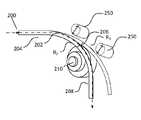
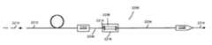
도 1은 다양한 빔 특성을 가지는 레이저 빔을 제공하기 위한 광섬유 구조를 도시한 것이고;
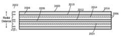
도 2는 가변 빔 특성을 가지는 빔의 전달하기 위한 예시적인 광섬유 구조의 단면도를 도시한 것이고;
도 3은, 가변 빔 특성을 가지는 빔을 제공하기 위한 광섬유를 섭동시키는 방법의 일 예를 나타낸 것이고;
도 4는, 상이한 광섬유 굽힘 반경에 대한 광섬유의 제1 길이부에 대해 최저 차수 모드(LP01)의 계산된 공간 프로파일을 나타내는 그래프이고;
도 5는 빔 특성을 변경하기 위한 광섬유가 거의 직선일 때, 접합부에서의 2차원 강도 분포의 일 예를 나타낸 것이고;
도 6은 빔 특성을 변경하기 위한 광섬유가 광섬유의 제2 길이부의 특정 속박 영역을 우선적으로 여기하도록 선택된 반경으로 구부러질 때, 접합부에서의 2차원 강도 분포의 일 예를 나타낸 것이고;
도 7 내지 도 10은, 도 2에 나타난 빔 특성을 변경하기 위한 광섬유의 다양한 굽힘 반경에 대한 추가 출력 빔을 예시하기 위한 실험 결과를 도시한 것이고;
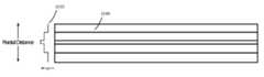
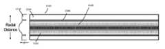
도 11 내지 도 16은, 광섬유 조립체에서 빔 특성 조정을 가능하게 하기 위한 광섬유의 예시적인 제1 길이부의 단면도를 나타내는 것이고;
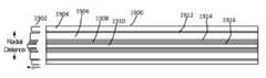
도 17 내지 도 19는, 광섬유 조립체에서 조정된 빔 특성을 속박하기 위한 예시적인 광섬유의 제2 길이부("속박 광섬유")의 단면도를 나타낸 것이고;
도 20 및 도 21은, 다양한 빔 특성을 제공하도록 형성된 광섬유 조립체에서 조정된 빔을 속박하고 발산 각도를 변경하기 위한 예시적인 광섬유의 제2 길이부의 단면도를 나타낸 것이고;
도 22a는 공급 광섬유와 프로세스 헤드 사이에 배치되어 다양한 빔 특성을 제공하도록 형성된 광섬유 조립체를 포함하는 예시적인 레이저 시스템을 나타낸 것이고;
도 22b는 공급 광섬유와 프로세스 헤드 사이에 배치되어 다양한 빔 특성을 제공하도록 형성된 광섬유 조립체를 포함하는 예시적인 레이저 시스템을 나타낸 것이고;
도 23은 공급 광섬유와 다중 프로세스 광섬유 사이에 배치되어 다양한 빔 특성을 제공하도록 형성된 광섬유 조립체를 나타낸 것이고;
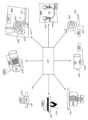
도 24는 본 명세서에 제공된 다양한 예에 따른 제공되는 다양한 빔 특성을 제공하기 위한 다양한 섭동 조립체의 예를 나타낸 것이고;
도 25는 광빔의 변경된 특성을 조정하고 유지하기 위한 예시적인 과정을 나타낸 것이고;
도 26 내지 도 28은 광섬유 조립체에서 조정된 빔 특성을 속박하기 위한 예시적인 광섬유의 제2 길이부("속박 광섬유")를 도시한 단면도이다.BRIEF DESCRIPTION OF THE DRAWINGS The accompanying drawings, in which like reference numerals indicate like elements, are incorporated in and constitute a part of this specification, which together with the above description explain the advantages and principles of the presently disclosed technology.
in the drawing,
1 shows an optical fiber structure for providing a laser beam having various beam characteristics;
2 illustrates a cross-sectional view of an exemplary fiber optic structure for delivery of a beam having tunable beam characteristics;
Figure 3 shows an example of a method for perturbing an optical fiber to provide a beam with variable beam characteristics;
4 is a graph showing the calculated spatial profile of the lowest order mode (LP01 ) for the first length of the optical fiber for different optical fiber bending radii;
Fig. 5 shows an example of a two-dimensional intensity distribution at a junction when an optical fiber for changing beam characteristics is substantially straight;
Fig. 6 shows an example of a two-dimensional intensity distribution at a junction when an optical fiber for changing beam characteristics is bent with a radius selected to preferentially excite a specific confinement region of a second length of the optical fiber;
7 to 10 show experimental results for illustrating additional output beams for various bending radii of optical fibers for changing the beam characteristics shown in FIG. 2;
11-16 show cross-sectional views of exemplary first lengths of optical fibers for enabling beam characteristic adjustment in optical fiber assemblies;
17-19 show cross-sectional views of a second length of an exemplary optical fiber ("tethered optical fiber") for confining adjusted beam characteristics in an optical fiber assembly;
20 and 21 show cross-sectional views of a second length of an exemplary optical fiber for confining a steered beam and varying the divergence angle in an optical fiber assembly configured to provide various beam characteristics;
22A shows an exemplary laser system that includes an optical fiber assembly disposed between a feed optical fiber and a process head and configured to provide various beam characteristics;
22B shows an exemplary laser system that includes an optical fiber assembly disposed between a feed optical fiber and a process head and configured to provide various beam characteristics;
Figure 23 shows an optical fiber assembly formed to provide various beam characteristics disposed between a feed optical fiber and a multiprocess optical fiber;
24 shows examples of various perturbation assemblies for providing various beam characteristics provided according to various examples provided herein;
25 illustrates an exemplary process for adjusting and maintaining altered characteristics of a light beam;
26-28 are cross-sectional views illustrating a second length of an exemplary optical fiber for confining adjusted beam characteristics in an optical fiber assembly ("constrained optical fiber").
이 명세서 및 청구 범위 전체에 걸쳐서, 단수 형태 "a", "an" 및 "the"는 문맥상 명확하게 다르게 지시하지 않는 한 복수 형태를 포함한다. 추가적으로, 용어 "포함하다(include)"는 "포함하다(comprise)"를 의미한다. 또한, "결합된(coupled)"이라는 용어는 결합된 물품들 사이의 중간 요소들의 배제를 의미하지 않는다. 또한, "수정(modify)" 및 "조정(adjust)"은 "변경(alter)"을 의미하도록 상호 교환적으로 사용된다.Throughout this specification and claims, the singular forms “a”, “an” and “the” include the plural forms unless the context clearly dictates otherwise. Additionally, the term “include” means “comprise”. Also, the term "coupled" does not imply the exclusion of intervening elements between the coupled articles. Also, “modify” and “adjust” are used interchangeably to mean “alter”.
본 명세서에 기술된 시스템, 장치 및 방법은 어떤 식으로든 제한되게끔 해석되어서는 안 된다. 대신에, 본 개시는 개시된 다양한 실시 형태의 신규하고 비-명백한 특징 및 양태가 단독, 다양한 조합 및 서로의 서브 조합으로 직접적으로 나타난다. 개시된 시스템, 방법 및 장치는 특정 양태, 특징 또는 그들의 조합으로 한정되지 않으며, 또한, 개시된 시스템, 방법 및 장치는 임의 하나 이상의 특정 이점이 존재하거나 문제가 해결되는 것을 필요로 하지 않는다. 임의의 동작 이론은 설명을 용이하게 하기 위한 것이지만, 개시된 시스템, 방법 및 장치는 그러한 동작 이론에 제한되지 않는다.The systems, devices and methods described herein should not be construed as limiting in any way. Instead, the disclosure presents directly the novel and non-obvious features and aspects of the various disclosed embodiments, alone, in various combinations and subcombinations of one another. The disclosed systems, methods, and devices are not limited to any particular aspect, feature, or combination thereof, and furthermore, the disclosed systems, methods, and devices do not require any one or more particular advantages or problems to be present. Any theory of operation is intended to facilitate explanation, but the disclosed systems, methods and apparatus are not limited to such theory of operation.
개시된 방법 중 일부 동작이 편리한 소개를 위해 특정 순차적 순서로 설명되었지만, 후술하는 특정 언어에 의해 특정 순서가 요구되지 않는 한, 이러한 방식의 설명은 재배치를 포함하는 것으로 이해하여야 한다. 예를 들어, 순차적으로 기술된 동작은 경우에 따라 재배치되거나 동시에 수행될 수 있다. 또한, 간략화를 위하여, 첨부된 도면은 개시된 시스템, 방법 및 장치가 다른 시스템, 방법, 장치와 같이 결합되어 사용될 수 있는 다양한 방식들을 나타내지 않을 수 있다. 또한, 설명은 개시된 방법을 설명하기 위하여 때때로 "생성(produce)" 및 "제공(provide)"과 같은 용어를 사용한다. 이런 용어들은 수행되는 실제 작업의 상위 수준의 추상적 개념이다. 이들 용어들에 대응하는 실제 동작은 특정 구현예에 따라 달라질 수 있으며, 당업자는 쉽게 알 수 있을 것이다.Although some operations of the disclosed methods have been described in a specific sequential order for convenience of introduction, it should be understood that description in this manner encompasses reordering, unless a specific order is required by specific language discussed below. For example, operations described sequentially may be rearranged or performed concurrently according to circumstances. Also, for purposes of brevity, the accompanying drawings may not represent the various ways in which the disclosed systems, methods and devices may be used in combination with other systems, methods and devices. Additionally, the description sometimes uses terms such as “produce” and “provide” to describe the disclosed method. These terms are high-level abstractions of the actual work being performed. Actual operations corresponding to these terms may vary depending on the particular implementation, and will be readily apparent to those skilled in the art.
일부 예에서, 값, 절차 또는 장치는 "최저(lowest)", "최상(best)", "최소(minimum)" 등으로 지칭된다. 그러한 설명은 사용된 많은 기능적 대안 중에서 선택이 이루어질 수 있고, 그러한 선택들은 더 낫거나, 더 작거나 또는 기타 다른 선택들보다 더 바람직할 필요는 없다는 것을 나타내도록 하기 위하여 사용될 수 있다. 예들은 "위(above)", "아래(below)", "상부(upper)", "하부(lower)" 등으로 나타난 방향을 참조하여 설명된다. 이러한 용어들은 설명을 용이하게 하기 위해 사용된 것이지만, 특정 공간적 방향을 의미하지는 않는다.In some examples, a value, procedure, or device is referred to as “lowest,” “best,” “minimum,” or the like. Such a description may be used to indicate that selections may be made among the many functional alternatives used, and that such selections need not be better, smaller, or more desirable than other choices. Examples are described with reference to directions indicated as "above", "below", "upper", "lower", and the like. These terms are used to facilitate explanation, but do not imply a specific spatial orientation.
정의Justice
1. "빔 특성" 이라는 용어는 광학 빔을 설명하기 위하여 사용되는 다음 용어 중 하나 이상을 나타낸다. 일반적으로 대부분의 관심 대상인 빔 특성은 응용 분야 또는 광학 시스템에 따라 다르다1. The term “beam characteristics” refers to one or more of the following terms used to describe an optical beam: Generally, the beam characteristics of most interest are application or optical system dependent.
2. "빔 직경"이란 용어는 최대 방사 조도의 1/e2와 같은 방사 조도(강도)의 축을 따라 빔의 중심을 가로 지르는 거리로 정의한다. 여기 개시된 예는 일반적으로 방위각적으로 대칭 모드로 전파하는 빔을 사용하지만, 타원형 또는 다른 빔의 형태도 사용될 수 있고, 빔 직경은 상이한 축을 따라 상이할 수 있다. 원형 빔은 단일 빔 직경임을 특징으로 한다.2. The term “beam diameter” is defined as the distance across the center of the beam along the axis of irradiance (intensity) equal to 1/e2 of the maximum irradiance. The examples disclosed herein generally use beams propagating in an azimuthally symmetrical mode, but elliptical or other beam shapes may also be used, and the beam diameter may be different along different axes. Circular beams are characterized by a single beam diameter.
3. "스폿 크기"라는 용어는 최대 방사 조도의 중심점에서 1/e2 지점까지의 반경 거리(반지름)을 의미한다.3. The term “spot size” means the radial distance (radius) from the center of maximum irradiance to the point 1/e2 .
4. "빔 발산 분포"라는 용어는 전체 원주 각에 대한 힘을 의미한다. 이 양은 "각도 분포" 또는 "NA 분포"라고도 한다.4. The term "beam divergence distribution" means the force over the entire circumferential angle. This quantity is also referred to as the "angular distribution" or "NA distribution".
5. "빔 파라미터 곱(BPP)"이라는 용어는 빔 반경(빔 허리에서 측정) 및 빔 발산 반각(먼 영역에서 측정)의 곱으로 정의된다. BPP의 단위는 일반적으로 mm-mrad이다.5. The term “beam parameter product (BPP)” is defined as the product of the beam radius (measured at the beam waist) and the half-angle of beam divergence (measured at the far field). The unit of BPP is usually mm-mrad.
6. "속박 광섬유"는 하나 이상의 속박 영역을 포함하는 광섬유를 의미하며, 속박 영역은 저 굴절률 영역(클래딩 영역)으로 둘러싸인 고 굴절률 영역(코어 영역)을 포함한다. 속박 광섬유의 RIP는 저 굴절률 영역(클래딩 영역)으로 둘러싸인 하나 이상의 고 굴절률 영역(코어 영역)을 포함할 수 있고, 여기서 빛은 고 굴절률 영역에 유도된다. 각 속박 영역 및 각 클래딩 영역은 스텝 인덱스 및 그레이디드 인덱스를 포함하되 이에 한정되지 않는 임의의 RIP를 포함할 수 있다. 속박 영역은 동심원일 수도 있고, 아닐 수도 있으며, 원형, 환형, 다각형, 아치형, 타원형, 불규칙한 형태 또는 이들의 임의의 조합과 같은 다양한 형태일 수 있다. 특정 속박 광섬유에서 속박 영역은 모두 동일한 형태를 가지거나 상이한 형태를 가질 수 있다. 나아가, 속박 영역은 동축이거나 서로에 대한 오프셋 축을 가질 수 있다. 속박 영역은 길이 방향에서 중심 축에 대하여 동일한 두께일 수 있거나, 길이 방향에서 중심 축에 대하여 두께가 달라질 수 있다.6. "Confined optical fiber" means an optical fiber comprising one or more confined regions, wherein the confined regions include a high refractive index region (core region) surrounded by a low refractive index region (cladding region). The RIP of a constrained optical fiber may include one or more high refractive index regions (core regions) surrounded by low refractive index regions (cladding regions), where light is directed into the high refractive index regions. Each constraining region and each cladding region may contain any RIP, including but not limited to a step index and a graded index. The constraining regions may or may not be concentric, and may be of various shapes, such as circular, annular, polygonal, arcuate, elliptical, irregular in shape, or any combination thereof. In a specific constrained optical fiber, the confinement regions may all have the same shape or may have different shapes. Further, the constraining regions may be coaxial or have axes offset from each other. The constraining regions may be of the same thickness with respect to the central axis in the longitudinal direction, or may have different thicknesses with respect to the central axis in the longitudinal direction.
7. "강도 분포"라는 용어는 선(1D 프로파일) 또는 평면(2D 프로파일)의 위치 함수에 따른 광강도로 나타낼 수 있다. 선 또는 평면은 일반적으로 빛의 전파 방향에 수직으로 취해진다. 이는 정량적 특성이다.7. The term "intensity distribution" can be expressed as the light intensity as a function of the position of a line (1D profile) or a plane (2D profile). A line or plane is usually taken perpendicular to the direction of light propagation. This is a quantitative characteristic.
8. "휘도"는 주어진 방향으로 진행하는 빛의 단위 면적 당 광도의 측광 측정값이다.8. "Luminance" is a photometric measure of luminous intensity per unit area of light traveling in a given direction.
9. "M2 값"("빔 품질 계수" 또는 "빔 전파 계수"라고도 함)는 M2 = 1이 회절 한계인 빔의 레이저 빔의 빔 품질을 정량화하기 위한 무차원 파라미터로, 큰 M2 값은 낮은 빔 품질에 대응한다. M2 은 BPP를 λ/π로 나눈 값과 동일하고, 여기서 λ는 미크론 단위의 빔의 파장이다(BPP가 mm-mrad 단위로 표현되는 경우).9. "M2 value" (also called "beam quality factor" or "beam propagation coefficient") is a dimensionless parameter for quantifying the beam quality of a laser beam of a beam for which M2 = 1 is the diffraction limit. A value corresponds to a low beam quality. M2 is equal to BPP divided by λ/π, where λ is the wavelength of the beam in microns (when BPP is expressed in units of mm-mrad).
10. 광학 시스템의 "개구수" 또는 "NA"라는 용어는 시스템이 빛을 수용하거나 방출할 수 있는 각도 범위를 특징 짓는 무차원의 수이다.10. The term "numerical aperture" or "NA" of an optical system is a dimensionless number that characterizes the angular range over which a system can accept or emit light.
11. "광강도"라는 용어는 공식(SI) 단위는 아니지만 표면상 또는 평면을 통과하는 단위 면적 당 입사 전력을 나타내는데 사용된다.11. The term "light intensity" is not a formal (SI) unit but is used to denote the incident power per unit area on a surface or through a plane.
12. "전력 밀도" 라는 용어는 "광강도"로도 불리지만, 단위 면적당 광강도를 의미한다.12. The term "power density", also referred to as "light intensity", means light intensity per unit area.
13. "방사 빔 위치"라는 용어는 광섬유 축에 수직인 방향으로 광섬유 코어의 중심에 대해 측정된 광섬유에서의 빔 위치를 의미한다.13. The term “radiation beam position” means the beam position in an optical fiber measured with respect to the center of the optical fiber core in a direction perpendicular to the axis of the optical fiber.
14. "방사 휘도"는 광 소스(예를 들어, 레이저)의 단위 면적에 의해 주어진 방향으로 단위 입체각 당 방출되는 방사이다. 방사 휘도는 빔 강도 분포 및/또는 빔 발산 프로파일 또는 분포를 변경함으로써 변경될 수 있다. 레이저 빔의 방사 휘도 프로파일을 변화시키는 능력은 BPP를 변화시키는 능력을 의미한다.14. "Radiation luminance" is the radiation emitted per unit solid angle in a given direction by unit area of a light source (eg, laser). The radiated brightness can be changed by changing the beam intensity distribution and/or the beam divergence profile or distribution. The ability to change the radiance profile of a laser beam means the ability to change the BPP.
15. "굴절률 프로파일" 또는 "RIP"라는 용어는 광섬유 축에 수직한 선(1D) 또는 평면(2D)을 따라 위치의 함수로서 나타난 굴절률을 의미한다. 많은 광섬유들은 방위각적으로 대칭이고, 이 경우 1D RIP는 임의의 방위각에 대해 동일하다.15. The term "refractive index profile" or "RIP" means the refractive index as a function of position along a line (1D) or plane (2D) perpendicular to the fiber axis. Many fibers are azimuthally symmetric, in which case the 1D RIP is the same for any azimuthal angle.
16. "스텝 인덱스 광섬유"는 광섬유 코어 내에서 평탄한(위치와 무관한 굴절률) RIP를 가진다.16. "Step index fiber" has a flat (position independent index of refraction) RIP within the fiber core.
17. "그레이디드 인덱스 광섬유"는 반경 위치가 증가함에 따라(즉, 광섬유 코어의 중심으로부터 거리가 증가함에 따라) 굴절률이 감소하는 RIP를 갖는다.17. A “graded index optical fiber” has a RIP in which the refractive index decreases with increasing radial position (i.e., with increasing distance from the center of the fiber core).
18. "파라볼릭 인덱스 광섬유"는 광섬유의 중심으로부터 거리가 증가함에 따라 2차식으로 굴절률이 감소하는 그레이디드 인덱스 광섬유의 특별한 경우이다.18. "Parabolic index optical fiber" is a special case of graded index optical fiber in which the refractive index decreases quadratically as the distance from the center of the optical fiber increases.
빔 특성을 변경하기 위한 광섬유Optical fibers for changing beam characteristics
본 명세서에 개시된 방법, 시스템 및 장치는 비용, 복잡성, 광 손실 또는 전술한 종래의 방법들의 다른 결점을 감소시킬 수 있는 가변 빔 특성(VBC)을 갖는 레이저 빔을 제공하도록 동작 가능한 광섬유를 제공하도록 형성된다. VBC 광섬유는 다양한 광빔 특성을 변경하도록 형성된다. 이러한 빔 특성은 VBC 광섬유를 사용하여 조절할 수 있으므로 사용자들이 광범위한 레이저 프로세싱 응용분야의 특정 요구에 맞도록 다양한 빔 특성을 조절할 수 있게 된다. 예를 들어, VBC 광섬유는 빔 직경, 빔 발산 분포, BPP, 강도 분포, M2 값, NA, 광강도, 전력 밀도, 방사 빔 위치, 방사 휘도, 스폿 크기 등 또는 이들의 조합을 조절할 수 있도록 사용된다.The methods, systems, and apparatus disclosed herein are formed to provide an optical fiber operable to provide a laser beam with tunable beam characteristics (VBC) that can reduce the cost, complexity, light loss, or other drawbacks of the conventional methods described above. do. VBC optical fibers are formed to change various light beam characteristics. These beam characteristics can be tuned using VBC fiber, allowing users to tune a variety of beam characteristics to meet the specific needs of a wide range of laser processing applications. For example, VBC fiber is used to adjustthe beam diameter, beam divergence distribution, BPP, intensity distribution, M2 value, NA, light intensity, power density, radiation beam position, radiation luminance, spot size, etc., or combinations thereof. do.
일반적으로, 개시된 기술은 레이저 빔 및/또는 광섬유의 제1 길이부를 다양한 방법(예를 들어, 광섬유를 굽히거나 하나 이상의 섭동을 도입)으로 섭동시키고, 광섬유의 제2 길이부에서 조정된 빔 특성을 완전히 또는 부분적으로 유지시킴으로써 조정될 수 있는 광섬유 내의 레이저 빔 특성의 레이저 빔을 광섬유 내로 결합시키는 것을 포함한다. 광섬유의 제2 길이부는 조정된 빔 특성을 유지 및/또는 더 변경하도록 특별히 형성된다. 경우에 따라, 광섬유의 제2 길이부는 최종 사용(예를 들어, 재료 가공)을 위하여 레이저 빔 전달을 통해 조정된 빔 특성을 보존한다. 광섬유의 제1 및 제2 길이부는 동일한 또는 상이한 광섬유를 포함할 수 있다.In general, the disclosed technique involves perturbing a laser beam and/or a first length of an optical fiber in various ways (eg, bending the optical fiber or introducing one or more perturbations), and adjusting the beam characteristics in the second length of the optical fiber. It involves coupling a laser beam into an optical fiber of the characteristics of the laser beam within the optical fiber that can be tuned by fully or partially maintaining. The second length of the optical fiber is specially formed to maintain and/or further alter the tuned beam characteristics. Optionally, the second length of the optical fiber preserves the adjusted beam characteristics through laser beam delivery for end use (eg, material processing). The first and second lengths of optical fiber may include the same or different optical fibers.
개시된 기술은 광섬유 레이저 및 광섬유 결합 레이저와 호환 가능하다. 광섬유 결합 레이저는 일반적으로 스텝 인덱스 굴절률 프로파일(RIP), 즉 광섬유 코어 내에서 평평하거나 일정한 굴절률을 갖는 전달 광섬유를 통하여 출력을 전달한다. 실제로, 전달 광섬유의 RIP는 광섬유의 설계에 따라 완전히 평평하지는 않을 수 있다. 중요한 파라미터는 광섬유 코어 직경(dcore) 및 NA이다. 중심 코어 직경은 일반적으로 10 -1000 미크론 범위(다른 값들이 가능하더라도)이고, NA는 일반적으로 0.06 내지 0.22의 범위(다른 값들이 가능하더라도)이다. 레이저의 전달 광섬유는 프로세스 헤드 또는 가공할 재료에 직접적으로 유입되거나, 광섬유 대 광섬유 커플러(FFC) 또는 광섬유 대 광섬유 스위치(FFS)에 유입될 수 있고, 전달 광섬유로부터 프로세스 헤드 또는 가공할 재료로 빔을 전송하는 프로세스 광섬유로 빛을 결합시킨다.The disclosed technology is compatible with fiber lasers and fiber coupled lasers. Fiber-coupled lasers typically deliver power through a delivery fiber that has a step-index refractive index profile (RIP), i.e., a flat or constant index of refraction within the fiber core. In practice, the RIP of the delivery fiber may not be completely flat depending on the design of the fiber. Important parameters are the fiber core diameter (dcore ) and NA. The central core diameter is typically in the range of 10-1000 microns (although other values are possible), and the NA is generally in the range of 0.06 to 0.22 (although other values are possible). The laser's delivery fiber can enter either directly into the process head or the material to be machined, or into a fiber-to-fiber coupler (FFC) or fiber-to-fiber switch (FFS), and directs the beam from the delivery fiber to the process head or material to be machined. It couples the light into process fibers that transmit it.
대부분의 재료 가공 툴, 특히 고전력(>1 kW)인 것들은 다중 모드(MM) 광섬유를 사용하지만, 일부는 더 낮은 dcore 및 NA 범위의 단일 모드(SM) 광섬유를 사용한다. SM 광섬유의 빔 특성은 광섬유 파라미터에 의해 고유하게 결정된다. 그러나, MM 광섬유의 빔 특성은 광섬유에 결합된 레이저 소스, 광섬유로의 발사 또는 접착 조건, 광섬유 RIP 및 광섬유의 정적 및 동적 형상(굽힘, 코일링, 움직임, 마이크로 벤딩 등)에 따라 달라질 수 있다(단위 대 단위 및/또는 레이저 전력 및 시간의 함수로). SM 및 MM 전달 광섬유 모두에 대해, 빔 특성은 주어진 재료 처리 작업에 대해 최적이 아닐 수 있으며, 작업 범위에 대해 최적이 아닐 가능성이 높고, 특정 처리 작업을 위해 이를 맞춤화 또는 최적화 하기 위하여 빔 특성을 체계적으로 변경할 수 있었으면 하는 바람이 동기부여가 되었다.Most material processing tools, especially those with high power (>1 kW), use multimode (MM) fiber, but some use single mode (SM) fiber in the lower dcore and NA range. The beam characteristics of SM fibers are uniquely determined by fiber parameters. However, the beam characteristics of a MM fiber may vary depending on the laser source coupled to the fiber, firing or bonding conditions into the fiber, fiber RIP, and the static and dynamic shape of the fiber (bending, coiling, motion, microbending, etc.) unit to unit and/or as a function of laser power and time). For both SM and MM delivery fibers, the beam properties may not be optimal for a given material processing task, and are likely not optimal for a range of tasks, and beam properties may need to be systematically modified to tailor or optimize them for a particular processing task. The desire to be able to change to was the motivation.
일 실시예에서, VBC 광섬유는 제1 길이부 및 제2 길이부를 가질 수 있으며, 빔 특성의 원하는 가변성을 제공하도록 전달 광섬유 및 프로세스 헤드 사이에 인-파이버 디바이스로서 형성될 수 있다. 상기 빔의 조정을 가능하게 하기 위하여 섭동 장치 및/또는 조립체가 상기 VBC 섬유에 매우 근접하게 배치 및/또는 상기 VBC 섬유에 결합되고, 이는 광섬유의 제1 길이부에서 빔 특성이 변경되도록 제1 길이부에서 빔을 섭동시키는 역할을 하며, 변화된 빔 특성은 광섬유의 제2 길이부에 빔이 전파됨에 따라 보존되거나 더 변하게 된다. 섭동된 빔은 조정된 빔 특성을 보존하도록 형성된 VBC 광섬유의 제2 길이부로 발사된다. 광섬유의 제1 및 제2 길이부는 동일하거나 상이한 광섬유일 수 있고/있거나, 광섬유의 제2 길이부는 속박 광섬유를 포함할 수 있다. VBC 광섬유의 제2 길이부에 의해 보존되는 빔 특성은 빔 직경, 빔 발산 분포, BPP, 강도 분포, 휘도, M2 값, NA, 광강도, 전력 밀도, 방사 빔 위치, 방사 휘도, 스폿 크기 등 또는 이들의 임의의 조합 중 어느 것을 포함할 수 있다.In one embodiment, the VBC fiber may have a first length and a second length and may be formed as an in-fiber device between the delivery fiber and the process head to provide desired variability in beam characteristics. A perturbation device and/or assembly is placed in close proximity to and/or coupled to the VBC fiber to enable steering of the beam, which has a first length of the fiber such that the beam characteristics change in the first length of the fiber. It serves to perturb the beam in the first section, and the changed beam characteristics are preserved or further changed as the beam propagates in the second length of the optical fiber. The perturbed beam is emitted into a second length of the VBC fiber shaped to preserve the tuned beam characteristics. The first and second lengths of optical fibers may be identical or different optical fibers, and/or the second lengths of optical fibers may include tethered optical fibers. Beam characteristics preserved by the second length of the VBC optical fiber include beam diameter, beam divergence distribution, BPP, intensity distribution, luminance, M2 value, NA, light intensity, power density, radiation beam position, radiation luminance, spot size, etc. or any combination of these.
도 1은 빔 특성을 변화시키도록 자유 공간 광학 장치의 사용 필요 없이 가변 빔 특성을 갖는 레이저 빔을 제공하기 위한 예시적인 VBC 광섬유(100)를 도시한다. VBC 광섬유(100)는 광섬유의 제1 길이부(104) 및 광섬유의 제2 길이부(108)를 포함한다. 광섬유의 제1 길이부(104) 및 광섬유의 제2 길이부(108)는 같거나 다른 광섬유일 수 있으며, 같거나 다른 RIP를 가질 수 있다. 광섬유의 제1 길이부(104) 및 광섬유의 제2 길이부(108)는 접합부에 의해 함께 결합될 수 있다. 광섬유의 제1 길이부(104) 및 광섬유의 제2 길이부(108)는 다른 방법으로 결합되거나, 이격되거나, 광섬유의 다른 길이부, 자유공간광학장치, 접착제, 굴절률-매칭 재료 등 또는 이들의 임의의 조합과 같은 삽입 구성요소를 통해 연결될 수 있다.1 shows an
섭동 장치(110)는 섭동 영역(106)에 인접하게 배치되고/되거나 섭동 영역(106)을 둘러싼다. 섭동 장치(110)는 장치, 조립체, 인-파이버 구조, 및 또는 다른 특징부일 수 있다. 섭동 장치(110)는 광빔(102)의 하나 이상의 빔 특성을 조정하기 위하여 적어도 광섬유의 제1 길이부(104), 광섬유의 제2 길이부(108) 또는 이들의 조합 내의 광빔(102)을 섭동시킨다. 섭동 장치(110)에 의한 섭동에 응답하는 빔(102) 조정은 광섬유의 제1 길이부(104), 광섬유의 제2 길이부(108) 또는 그들의 조합에서 일어날 수 있다. 섭동 영역(106)은 다양한 폭에 걸쳐 연장될 수 있고, 광섬유의 제2 길이부의 일부로 연장되거나 연장되지 않을 수 있다. 빔(102)이 VBC 광섬유(100) 내로 전파됨에 따라, 섭동 장치(110)는 광섬유를 섭동시키고 빔(102) 특성을 조정하기 위하여 VBC 광섬유(100)에 물리적으로 작용한다. 대안으로, 섭동 장치(110)는 빔 특성을 변경시키기 위하여 빔(102)에 직접 작용할 수 있다. 조정된 후에, 섭동된 빔(112)은 광섬유의 제2 길이부(108)에서 완전히 또는 부분적으로 보존될 수 있는 빔(102)에 비하여 상이한 빔 특성을 갖는다. 다른 예에서, 섭동 장치(110)는 접합부 부근에 배치될 필요가 없다. 또한, 접합부는 전혀 필요하지 않을 수 있고, 예를 들어 VBC 광섬유(100)는 단일 광섬유일 수 있거나, 광섬유의 제1 길이부 및 광섬유의 제2 길이부는 이격될 수 있거나, 작은 갭으로 고정될 수 있다(에어 스페이스, 또는 광 시멘트 또는 굴절률 매칭 재료와 같은 광학 재료로 채워짐).The
섭동된 빔(112)은 광섬유의 제2 길이부로 발사되고, 섭동된 빔(112)이 광섬유의 제2 길이부(108)의 출력에서 조정된 빔 특성을 나타내도록 전파함에 따라 섭동된 빔(112) 특성은 대체로 유지되거나 계속하여 변하게 된다. 예를 들어, 새로운 빔 특성은 조정된 강도 분포를 포함할 수 있다. 예를 들어, 변경된 빔의 강도 분포는 광섬유의 제2 길이부의 구조적으로 경계를 이루는 다양한 속박영역에서 보존될 것이다. 따라서, 빔 강도 분포는 특정 레이저 처리 작업에 최적화되는 원하는 빔 강도 분포로 조정될 수 있다. 일반적으로, 섭동된 빔(112)이 광섬유의 제1 길이부의 조건 및 섭동 장치(110)에 의한 섭동에 응답하여 발사되는 속박 영역을 채우기 위하여 광섬유의 제2 길이부에서 빔이 전파됨에 따라 섭동된 빔(112)의 강도 분포는 변화한다. 또한, 발사 조건 및 광섬유 특성에 따른 광섬유의 제2 길이 부분에서의 빔의 전파에 따라 각도 분포가 변화할 수 있다. 일반적으로, 광섬유는 입력 발산 분포의 대부분을 보존하지만 만약, 입력 발산 분포가 좁고/좁거나 만약, 광섬유가 불규칙성 또는 발산 분포를 섭동시키는 의도적인 특징을 가지고 있다면 발산 분포는 넓어질 수 있다. 다양한 속박 영역, 섭동 및 광섬유의 제2 길이부의 광섬유 특징은 아래에 더 자세히 설명되어 있다. 빔(102 및 112)은 가변 빔 특성을 제공하기 위하여 VBC 광섬유(100)를 통해 빔이 어떻게 전파될 수 있는지 설명하기 위한 개념적인 추상 개념이며, 특정 광빔의 거동을 정밀하게 모델링하는 것을 의도한 것은 아니다.The
VBC 광섬유(100)는 PCVD(플라즈마 화학 기상 증착법, Plasma Chemical Vapor Deposition), OVD(외부 증기 증착법, Outside Vapor Deposition), VAD (증기 축 증착법, Vapor Axial Deposition), MOCVD (금속 - 유기 화학 기상 증착법, Metal-Organic Chemical Vapor Deposition) 및/또는 DND(직접 나노 입자 증착법, Direct Nanoparticle Deposition)를 포함하는 다양한 방법에 의하여 제조될 수 있다. VBC 광섬유(100)는 다양한 물질을 포함할 수 있다. 예를 들어, VBC 광섬유(100)는 SiO2, GeO2로 도핑된 SiO2, 게르마노실리케이트(germanosilicate), 오산화인(phosphorus pentoxide), 포스포실리케이트(phosphosilicate), Al2O3, 알루미노 실리케이트 등 또는 이들의 임의의 조합을 포함할 수 있다. 속박 영역은 불소, 붕소 또는 이들의 임의의 조합으로 도핑된 클래딩에 의해 나누어질 수 있다. Er3+ (에르븀, erbium), Yb3+ (이테르븀, ytterbium), Nd3+ (네오디뮴, neodymium), Tm3+ (툴륨, thulium), Ho3+ (홀뮴, holmium) 등 또는 이들의 임의의 조합과 같은 희토류 이온을 포함하는 다른 도펀트가 활성 광섬유에 추가될 수 있다. 대안적으로, VBC 광섬유(100)는 광결정 광섬유 또는 미세 구조 광섬유를 포함할 수 있다.The VBC
VBC 광섬유는 연속파 및 펄스화된 광섬유 레이저, 디스크 레이저, 고체 레이저 또는 다이오드 레이저(물리적 제약을 제외하고 펄스 속도는 제한되지 않음)를 포함하는 다양한 광섬유, 광섬유 광학 장치 또는 광섬유 레이저 장치 중 임의의 것에 사용하기에 적합하다. 또한, 광섬유뿐만 아니라 평면 도파관 또는 다른 타입의 도파관에서의 구현은 청구된 기술범위 내에 있다.VBC fibers are used in any of a variety of optical fibers, including continuous wave and pulsed fiber lasers, disk lasers, solid state lasers or diode lasers (pulse speed not limited except for physical constraints), fiber optic devices or fiber laser devices. suitable for doing Also, implementation in planar waveguides or other types of waveguides as well as optical fibers is within the scope of the claimed technology.
도 2는 광빔의 빔 특성을 조정하기 위한 예시적인 VBC 광섬유(200)의 단면도를 도시한다. 예를 들어, VBC 광섬유(200)는 재료 처리를 위해 빔을 프로세스 헤드로 전달할 수 있기 때문에 프로세스 광섬유일 수 있다. VBC 광섬유(200)는 광섬유의 제2 길이부(208)와 접합부(206)에서 접합되는 광섬유의 제1 길이부를 포함할 수 있다. 섭동 조립체(210)는 접합부(206)에 근접하게 배치된다. 섭동 조립체(210)는 VBC 광섬유(200)에서 전파되는 광빔(202)의 빔 특성의 조정이 가능하도록 형성된 다양한 장치 중 임의의 것일 수 있다. 예를 들어, 섭동 조립체(210)는 맨드릴 및/또는 접합부 부근에서 VBC 광섬유(200)의 굽힘 반경 및/또는 굽힘 길이를 변화시키는 수단을 제공하는 다른 장치일 수 있다. 섭동 장치의 다른 예는 도 24와 관련하여 후술된다.2 shows a cross-sectional view of an exemplary VBC
예를 들어, 광섬유의 제1 길이부(204)는 왼쪽 RIP 그래프에서 나타내는 것과 같이 파라볼릭-인덱스 RIP(212)를 갖는다. 빔(202)의 대부분의 강도 분포는 광섬유(204)가 직선 또는 거의 직선에 가까울 때, 광섬유(204)의 중심에 집중된다. 광섬유의 제2 길이부(208)는 오른쪽 RIP 그래프에서 보이는 것과 같은 RIP(214)를 가지는 속박 광섬유이다. 광섬유의 제2 길이부(208)는 속박 영역(216, 218 및 220)을 포함한다. 속박 영역(216)은 두 환형(또는 고리형) 속박 영역(218 및 220)으로 둘러싸인 중심 코어이다. 층(222 및 224)은 속박 영역(216, 218 및 220) 사이의 저 굴절률 물질의 구조적 장벽이고, 일반적으로 "클래딩" 영역으로 지칭된다. 예를 들어, 층(222 및 224)은 플루오로 실리케이트의 링을 포함할 수 있고, 일부 실시예에서, 플루오로 실리케이트 클래딩 층은 비교적 얇다. 다른 물질들도 사용될 수 있으며 청구대상은 이와 관련하여 제한되지 않는다.For example, the
일 실시예에서, 빔(202)이 VBC 광섬유(200)를 따라 전파됨에 따라, 섭동 조립체(210)는 빔 특성을 조정하고 조정된 빔(226)을 생성하기 위하여 광섬유(208) 및/또는 빔(202)에 물리적으로 작용할 수 있다. 현재의 예에서, 빔(202)의 강도 분포는 섭동 조립체(210)에 의하여 변경된다. 빔(202) 조정 후에, 조정된 빔의 강도 분포는 외곽 속박 영역(218, 220)에 집중되고, 중심 속박 영역(216)에서 비교적 작은 강도로 집중된다. 각각의 속박 영역 (216, 218 및/또는 220)은 장벽층(222 및 224)에서 저 굴절률 물질의 얇은 층에 의해 격리되기 때문에, 광섬유의 제2 길이부(208)는 실질적으로 조정된 빔(226)의 조정된 강도분포를 실질적으로 유지할 수 있다. 빔은 주어진 속박 영역 내에서 방위각적 분포를 전형적으로 갖게 되지만, 광섬유의 제2 길이부(208)를 따라 전파됨에 따라 속박 영역 사이로 전이가(상당히) 발생하지는 않을 것이다. 따라서, 조정된 빔(226)의 조정된 빔 특성은 하나의 영역에 집중되기 보다는 격리된 속박 영역(216, 218 및/또는 220) 내에서 대부분 보존될 것이고 이러한 조건은 적절히 조정된 빔(226)을 생성함으로써 달성될 수 있다.In one embodiment, as the
일 실시예에서, 코어 속박 영역(216) 및 환형 속박 영역(218 및 220)은 용융 실리카 유리를 포함할 수 있고, 속박 영역을 정의하는 클래딩(222 및 224)은 플루오로 실리케이트 유리를 포함할 수 있다. 게르마노실리케이트(germanosilicate), 포스포실리케이트(phosphosilicate), 알루미노 실리케이트 등 또는 이들의 조합을 포함하는 다른 물질들은 다양한 속박 영역(216, 218 및 220)을 형성하기 위하여 사용될 수 있으나 청구대상은 이로 제한되지 않는다. 용융 실리카, 보로실리케이트(borosilicate) 등 또는 이들의 조합을 포함하는 다른 물질은 장벽 고리(222 및 224)를 형성하기 위하여 사용될 수 있지만, 청구대상은 이로 제한되지 않는다. 다른 실시예에서, 광섬유 또는 도파관은 다양한 고분자, 플라스틱 또는 결정질 물질을 포함하거나 이들로 구성된다. 일반적으로 코어 속박 영역은 장벽/클래딩 영역에 인접한 부분보다 큰 굴절률을 갖는다.In one embodiment,
일부 예에서, 빔 프로파일의 미세 조정을 위하여 빔 변위에 대한 빔 조절의 세분성을 증가시키도록 광섬유의 제2 길이부에서 속박 영역의 수를 증가시키는 것이 바람직할 수 있다. 예를 들어, 속박 영역은 단계별 빔 변위를 제공하도록 형성될 수 있다.In some instances, it may be desirable to increase the number of confinement regions in the second length of the optical fiber to increase the granularity of beam steering relative to beam displacement for fine tuning of the beam profile. For example, the confinement region can be formed to provide step-by-step beam displacement.
도 3은 광빔의 가변 빔 특성을 제공하기 위한 광섬유를 섭동시키는 예시적인 방법을 도시한다. 광섬유의 굽힘 반경을 변경하는 것은 광섬유 내의 방사 빔 위치, 발산 각 및/또는 빔의 방사 휘도 프로파일을 변경시킬 수 있다. VBC 광섬유(200)의 굽힘 반경은 섭동 조립체로서, 계단식 맨드릴 또는 원뿔을 사용함으로써 접합부에 대한 제1 굽힘 반경(R1)에서 제2 굽힘 반경(R2)로 감소할 수 있다. 추가적으로 또는 대안적으로, 맨드릴 또는 원뿔의 맞물림 길이는 달라질 수 있다. 롤러(250)는 섭동 조립체(210)를 가로질러 VBC 광섬유와 결합하도록 사용될 수 있다. 일 실시예에서. 롤러(250)와 광섬유(200)의 맞물림 양은 고정된 맨드릴 반경의 광섬유(200)의 외곽 속박 영역(218 및 220)으로 강도 프로파일 분포를 이동시키는 것으로 나타났다. 클램핑 조립체, 가요성 튜빙 등 또는 이들의 조합과 같이 광섬유(200)의 굽힘 반경을 변화시키기 위한 다양한 방법이 있으나 청구대상은 이에 제한되지 않는다. 다른 예에서, 특정 굽힘 직경에 대해, VBC 광섬유(200)가 굴곡되는 길이는 또한 제어되고 재생 가능한 방식으로 빔 특성을 변경시킬 수 있다. 예를 들어, 광섬유가 특정 굽힘 반경에서 굴곡되는 굽힘 반경 또는 길이를 변경하는 것은 또한 빔의 강도 분포를 변경할 수 있어 하나 이상의 모드가 광섬유 코어의 중심으로부터 방사상으로 이동될 수 있다.3 shows an exemplary method of perturbing an optical fiber to provide variable beam characteristics of a light beam. Changing the bend radius of an optical fiber can change the position of a radiation beam within the optical fiber, the angle of divergence, and/or the radiant brightness profile of the beam. The bend radius of the
접합부(206)를 가로지르는 광섬유의 굽힘 반경을 유지하는 것은 방사 빔 위치와 같은 빔 특성의 조정을 보장하고, 광빔(202)의 방사 휘도 프로파일은 광섬유의 제2 길이부로 발사되기 전에는 빔(202)의 섭동되지 않은 상태로 돌아가지 않을 것이다. 또한, 조정된 빔(226)의 위치, 방사 각 및/또는 강도 분포를 포함하는 조정된 방사 빔 특성은 VBC 광섬유(200)의 굽힘 반경의 감소 정도 및/또는 굽힘 길이의 정도에 기초하여 변할 수 있다. 따라서, 이 방법을 이용하여 특정 빔 특성을 얻을 수 있다.Maintaining the bend radius of the optical fiber across
현재의 예에서, 제1 RIP(212)를 갖는 광섬유의 제1 길이부(204)는 제2 RIP(214)를 갖는 광섬유의 제2 길이부와 접합부(206)에서 접합된다. 그러나, 빔(202)의 빔 특성의 섭동(마이크로-벤딩)을 가능하게 하고, 또한 조정된 빔의 보존을 가능하게 하도록 형성된 단일 RIP를 가지는 단일 광섬유를 사용하는 것도 가능하다. 이러한 RIP는 도 17, 18 및/또는 19에서 나타내는 광섬유가 보여주는 RIP와 유사할 수 있다.In the present example, a
도 7-10은 섭동 조립체(210)가 광섬유를 굴곡시키기 위하여 VBC 광섬유(200)에 작용할 때의 VBC 광섬유(도 2 및 도 3의 200)의 실험 결과를 제공하고 VBC 광섬유의 섭동에 대한 빔 응답을 도시한 것이다. 도 4-6은 시뮬레이션이고, 도 7-10은 실험 결과이며, 여기서 SM 1050 nm 소스로부터의 빔이 40 미크론 코어 직경을 갖는 입력 광섬유(미도시)로 발사되었다. 입력 광섬유는 광섬유의 제1 길이부(204)와 접합되었다.7-10 provide experimental results of a VBC fiber (200 in FIGS. 2 and 3) when a
도 4는 상이한 광섬유 굽힘 반경(402)에 대한 광섬유의 제1 길이부의 최저차수모드(LP01)의 계산된 프로파일을 도시한 예시적인 그래프(400)이고, 여기서 섭동 조립체(210)는 VBC 광섬유(200)를 굴곡시키는 것을 포함한다. 광섬유의 굽힘 반경이 감소함에 따라, VBC 광섬유(200)로 전파되는 광빔은 조정되고, 모드는 VBC 광섬유(200) 코어의 중심(404)에서 코어/클래딩 경계(이 예에서 r = 100 미크론에 위치)쪽으로 방사상으로 이동한다. 고차모드(LPln) 또한 굽힘에 따라 이동한다. 따라서, 직선 또는 거의 직선인 광섬유(매우 큰 굽힘 반경)인 LP01에 대한 곡선(406)은 VBC 광섬유(200)의 중심 또는 중심 부근에 위치한다. 굽힘 반경이 약 6 cm 일 때, LP01에 대한 곡선(408)은 VBC 광섬유(200)의 중심(406)으로부터 약 40 μm 방사상 위치로 이동된다. 굽힘 반경이 약 5 cm 일 때, LP01에 대한 곡선(410)은 VBC 광섬유(200)의 중심(406)으로부터 약 50 μm 방사상 위치로 이동된다. 굽힘 반경이 약 4 cm 일 때, LP01에 대한 곡선(412)은 VBC 광섬유(200)의 중심(406)으로부터 약 60 μm 방사상 위치로 이동된다. 굽힘 반경이 약 3 cm 일 때, LP01에 대한 곡선(414)은 VBC 광섬유(200)의 중심(406)으로부터 약 80 μm 방사상 위치로 이동된다. 굽힘 반경이 약 2.5 cm 일 때, LP01에 대한 곡선(416)은 VBC 광섬유(200)의 중심(406)으로부터 약 85 μm 방사상 위치로 이동된다. 모드의 형상은 비교적 일정하게 유지되고(코어의 가장자리에 접근할 때까지), 파라볼릭 RIP의 특정 속성임을 주목해야 한다. 그럼에도 불구하고, 이 속성은 일부 상황에서는 바람직하지만, VBC 기능에서는 필요하지 않으며, 다른 RIP가 사용될 수 있다.4 is an
일 실시예에서, VBC 광섬유(200)가 직선화된다면, LP01 모드는 광섬유의 중심 쪽으로 후퇴할 것이다. 따라서, 광섬유의 제2 길이부의 목적은 VBC 광섬유(200)의 중심에서 벗어난 속박 영역의 빔의 조정된 강도 분포를 "포획"하거나 속박하는 것이다. 광섬유(204 및 208) 사이의 접합부는 굽힘 영역에 포함되고, 따라서 이동된 모드는 고리-형태의 속박 영역(218, 210) 중 하나에 우선적으로 발사되거나 속박 영역들 사이에 분포될 것이다. 도 5 및 6은 이 효과를 설명한다.In one embodiment, if the
도 5는 VBC 광섬유(200)가 거의 직선일 때, 광섬유의 제2 길이부(208) 내의 접합부(206)에서의 2차원 강도 분포의 예를 나타낸 것이다. LP01- 및 LPln의 상당한 부분은 광섬유(208)의 속박 영역(216) 내에 있다. 도 6은 VBC 광섬유(200)가 광섬유의 제2 길이부(208)의 속박 영역(220, 가장 바깥쪽 속박 영역)을 우선적으로 여기시키기 위해 선택된 반경으로 굴곡될 때 광섬유의 제2 길이부(208) 내의 접합부(206)에서의 2차원 강도 분포를 나타낸 것이다. LP01- 및 LPln의 상당한 부분은 광섬유(208)의 속박 영역(220) 내에 있다.FIG. 5 shows an example of the two-dimensional intensity distribution at the
일 실시예에서, 광섬유의 제2 길이부(208)의 속박 영역(216)은 100 미크론의 직경을 갖고, 속박 영역(218)은 120 미크론 내지 200 미크론 사이의 직경이며, 속박 영역(220)은 220 미크론 내지 300 미크론 사이의 직경이다. 속박 영역(216, 218 및 220)은 속박 영역에 대해 0.22의 NA를 제공하는 10 ㎛ 두께의 플루오로 실리케이트 고리에 의해 나누어진다. 이와 다른 속박 영역의 내부 및 외부 직경, 속박 영역을 분리하는 고리의 두께, 속박 영역에 대한 NA 값, 속박 영역의 수가 사용될 수 있다.In one embodiment, the
표시된 파라미터와 함께 다시 도 5를 참고하면, VBC 광섬유(200)가 직선일 때 중심 속박 영역(216) 내에 전력의 약 90%를 포함하며, 속박 영역(216 및 218) 내에 전력의 약 100%를 포함한다. 이제 도 5를 참고하면, 광섬유(200)가 제2 고리 속박 영역(220)을 우선적으로 여기시키기 위하여 굴곡될 때, 전력의 거의 75%가 속박 영역(220) 내에 포함되고, 전력의 95% 이상이 속박 영역(218 및 220)에 포함된다. 이 계산은 LP01와 두 개의 고차 모드를 포함하며, 이는 2 - 4 kW 광섬유의 레이저에서 일반적이다.Referring again to FIG. 5 with the parameters indicated, when the
도 5 및 6으로부터 섭동 조립체(210)가 광섬유를 굴곡시키기 위하여 VBC 광섬유(200)에 작용하는 경우, 굽힘 반경은 광섬유의 제2 길이부(208)의 상이한 가이딩 속박 영역(216, 218 및 220)과 광섬유의 제1 길이부의 모달 강도 분포의 공간적 중첩을 결정한다. 굽힘 반경을 변경하는 것은 광섬유의 제2 길이부(208)의 출력에서 강도 분포를 변경할 수 있고, 빔의 직경 및 스폿 크기를 변경하는 것은 또한 방사 휘도 및 BPP 값을 변경할 수 있다. 이 스폿 크기의 조정은 자유공간광학장치를 포함하지 않는 전체 광섬유 구조에서 얻어질 수 있으며, 결과적으로 위에서 언급된 자유공간광학장치의 단점을 감소시키거나 제거시킬 수 있다. 이러한 조정은 굽힘 반경, 굽힘 길이, 광섬유 장력, 온도 또는 이하에서 언급되는 다른 섭동 등을 변경시키는 다른 섭동 조립체에 의해 얻어질 수 있다.5 and 6, when the
통상적인 재료 처리 시스템(예를 들어, 절단 또는 용접 기구)에서, 프로세스 광섬유의 출력은 프로세스 헤드에 의해 공작물에서 또는 그 근처에서 이미징된다. 도 5 및 도 6에서 보여지는 것과 같이 강도 분포를 변경하는 것은 원하는 것과 같이, 공정을 조정 및/또는 최적화하기 위하여 공작물에서의 빔 프로파일의 변화를 가능하게 한다. 위의 계산의 목적을 위하여 두 개의 광섬유의 특정 RIP가 가정되었지만, 다른 RIP도 가능하며, 청구대상은 이에 제한되지 않는다.In a typical material handling system (eg, a cutting or welding tool), the output of a process fiber is imaged at or near the workpiece by a process head. Varying the intensity distribution as shown in Figures 5 and 6 allows variation of the beam profile at the workpiece to adjust and/or optimize the process, as desired. Although a specific RIP of two fibers has been assumed for the purposes of the above calculations, other RIPs are possible and claimed subject matter is not limited thereto.
도 7-10은 도 2에서 나타난 VBC 광섬유(200)의 다양한 굽힘 반경에 대한 추가 출력 빔을 설명하기 위한 실험 결과(측정된 강도 분포)를 도시하였다.7-10 show experimental results (measured intensity distribution) for explaining additional output beams for various bending radii of the VBC
도 7에서 VBC 광섬유(200)가 직선일 때, 빔은 속박 영역(216)에 거의 완전히 속박된다. 굽힘 반경이 감소함에 따라, 강도 분포는 더 큰 직경으로 이동한다(도 8-10). 도 8은 우선적으로 속박 영역(218)으로 강도 분포를 이동시키기 위하여 VBC 광섬유(200)의 굽힘 반경이 선택될 때를 도시한다. 도 9는 속박 영역(220) 및 속박 영역(218)을 향하여 강도 분포를 바깥쪽으로 이동시키기 위하여 굽힘 반경이 더 감소 및 선택 될 때의 실험 결과를 도시한다. 도 10에서, 가장 작은 굽힘 반경에서 빔은 거의 "도넛 모드"이며, 대부분의 강도는 가장 바깥쪽의 속박 영역(220)에 있다.In FIG. 7, when the
접합부(206)에서의 일 측면으로부터의 속박 영역의 여기에도 불구하고, VBC 광섬유(200) 내에서 빔이 전파됨에 따른 속박 영역 내의 스크램블링 때문에 강도 분포는 방위각적으로 거의 대칭이다. 빔은 전파됨에 따라 전형적으로 방위각적인 스크램블링을 할 것이지만, 이 과정을 용이하게 하기 위하여 다양한 구조 또는 섭동(예를 들어, 코일)이 포함될 수 있다.Despite the excitation of the confined region from one side at
도 7-10에서 보여지는 실험에서 사용된 광섬유 파라미터들에 대하여, 특정 속박 영역은 일부 강도가 다수의 속박 영역 내에 위치하기 때문에 배타적으로 여기되지 않는다. 이러한 특징은 평평하거나 분산된 빔 강도 분포를 가짐으로써 최적화되는 향상된 재료 공정 응용을 가능하게 한다. 주어진 속박 영역의 더 깔끔한 여기를 필요로 하는 응용에서, 상이한 광섬유 RIP가 이 특징을 가능하게 하기 위하여 사용될 수 있다.For the fiber parameters used in the experiments shown in Figs. 7-10, certain confinement regions are not exclusively excited because some intensities are located within multiple confinement regions. This feature enables advanced material processing applications that are optimized by having a flat or dispersed beam intensity distribution. In applications that require cleaner excitation of a given confinement region, different fiber optic RIPs can be used to enable this feature.
도 7-10에서 보여지는 결과는 이 실험에서 사용되는 특정 광섬유와 관련되며, 세부 사항은 구현의 세부 사항에 따라 달라질 수 있다. 특히, 출력 빔의 공간 프로파일와 발산 분포 및 그들의 굽힘 반경에 대한 의존성은 사용된 특정 RIP, 접합 파라미터 및 제1 광섬유로 발사된 레이저 소스의 성질에 따라 달라진다.The results shown in Figures 7-10 are related to the specific optical fiber used in this experiment, the details of which may vary depending on the specifics of the implementation. In particular, the spatial profile and divergence distribution of the output beams and their dependence on the bend radius depend on the particular RIP used, the bonding parameters and the nature of the laser source launched into the first fiber.
도 2에 나타나는 것과 상이한 광섬유 파라미터가 사용될 수 있고, 이는 청구대상 범위 내에 있다. 구체적으로, 상이한 RIP, 코어 크기 및 형상은 상이한 입력 빔 프로파일과의 호환을 용이하게 하며, 상이한 출력 빔 특성을 가능하게 하기 위하여 사용될 수 있다. 도 2에 나타난 파라볼릭-인덱스 프로파일에 추가하여, 광섬유의 제1 길이부의 RIP의 예는 다른 그레이디드 인덱스 프로파일. 스텝 인덱스 프로파일, 받침대 디자인(즉, 섬유의 중심으로부터 거리가 멀어짐에 따라 점진적으로 낮은 굴절률을 갖는 중첩된 코어) 및 동일한 굴절률 값을 갖지만 중심 코어 및 주변 고리에 대한 다양한 NA 값을 갖는 중첩된 코어 디자인을 포함한다. 도 2에 나타난 프로파일에 추가하여, 광섬유의 제2 길이부의 RIP의 예는, 상이한 수의 속박 영역을 갖는 속박 광섬유, 일정하지 않은 두께의 한정 영역, 속박 영역에 대하여 상이하고/하거나 일정하지 않은 NA 값, RIP의 고 굴절률 및 저 굴절률 부분에 대한 상이한 굴절률 값, 비원형의 속박 영역(예를 들어, 타원형, 계란형, 다각형, 정사각형, 직사각형 또는 이들의 조합), 또한 도 26-28에서 더 상세히 설명될 다른 디자인을 포함한다. 또한, VBC 광섬유(200) 및 여기서 묘사되는 VBC 광섬유의 다른 예는 두 광섬유를 사용하는 것으로 한정되지는 않는다. 일부 예에서, 구현은 하나 또는 둘 이상의 광섬유를 사용하는 것을 포함한다. 일부 예에서, 광섬유는 축 방향으로 균일하지 않을 수 있다; 예를 들어, 광섬유 브래그 격자 또는 장주기 격자를 포함할 수 있거나, 직경은 광섬유의 길이 방향을 따라 달라질 수 있다. 또한, 섬유는 방위각적으로 대칭일 필요는 없고, 예를 들어, 코어는 사각형 또는 다각형 모양을 가질 수 있다. 고 굴절률 또는 굴절률 매칭 코팅(유리-중합체 계면에서 광을 차단하는) 및 저 굴절률 코팅(유리-중합체 계면에서 전반사에 의해 광을 안내하는)을 포함하는 다양한 광섬유 코팅(버퍼)이 사용될 수 있다. 일부 예에서, 다수의 광섬유 코팅이 VBC 광섬유(200)에 사용될 수 있다.Fiber parameters different from those shown in FIG. 2 may be used and are within the scope of the claims. Specifically, different RIPs, core sizes and shapes can be used to facilitate compatibility with different input beam profiles and enable different output beam characteristics. In addition to the parabolic-index profile shown in FIG. 2, an example of the RIP of the first length of the optical fiber is another graded index profile. Step index profiles, pedestal designs (i.e. nested cores with progressively lower refractive indices with increasing distance from the center of the fiber), and nested core designs with identical refractive index values but varying NA values for the central core and peripheral annulus includes In addition to the profile shown in FIG. 2, examples of RIPs of the second length of the optical fiber are: constrained fibers with different numbers of confined regions, confined regions of non-constant thickness, NAs that are different and/or non-constant for the confined regions. values, different refractive index values for the high and low index portions of the RIP, non-circular confinement regions (e.g., elliptical, oval, polygonal, square, rectangular or combinations thereof), also described in more detail in FIGS. 26-28. Other designs to be included. Also, the VBC
도 11-16은 광섬유의 제1 길이부에서 전파되는 광빔의 섭동에 응답하는 VBC 광섬유에서의 빔 특성의 조정을 가능하게 하기 위한 광섬유의 제1 길이부의 예를 보여주는 단면도이다. 광섬유의 제1 길이부에서 조정될 수 있는 빔 특성의 일부 예는 빔 직경, 빔 발산 분포, BPP, 강도 분포, M2 값, NA, 광강도 프로파일, 전력 밀도 프로파일, 방사 빔 위치, 방사 휘도, 스폿 크기 등 또는 이들의 임의의 조합이다. 도 11-16에 도시되고 이하에서 설명되는 광섬유의 제1 길이부는 단지 예일 뿐이고, VBC 광섬유 조립체에서 빔 특성의 조정을 가능하게 하도록 사용될 수 있는 다양한 광섬유의 제1 길이부의 철저한 설명을 제공하는 것은 아니다. 도 11-16에서 설명하는 물질, 적절한 RIP 및 다른 광섬유의 제1 길이부의 변수의 선택은 적어도 원하는 빔 출력에 따라 달라진다. 광범위한 섬유 변수가 고려되며, 그들은 청구대상 범위 내에 있다. 따라서, 청구 대상은 여기서 제공되는 예로 제한되지 않는다.11-16 are cross-sectional views showing examples of a first length of an optical fiber for enabling adjustment of beam characteristics in a VBC optical fiber responsive to perturbations of a light beam propagating in the first length of the optical fiber. Some examples of beam characteristics that can be adjusted in the first length of the optical fiber are beam diameter, beam divergence distribution, BPP, intensity distribution, M2 value, NA, light intensity profile, power density profile, radiation beam position, radiation luminance, spot size, etc. or any combination thereof. The first lengths of optical fibers shown in FIGS. 11-16 and described below are examples only and do not provide an exhaustive description of the first lengths of various optical fibers that can be used to enable tuning of beam characteristics in VBC fiber optic assemblies. . The choice of material, suitable RIP and other parameters of the first length of the optical fiber described in FIGS. 11-16 depends at least on the desired beam output. A wide range of fiber parameters are contemplated and they are within the scope of the claims. Accordingly, claimed subject matter is not limited to the examples provided herein.
도 11에서 광섬유의 제1 길이부(1100)는 스텝 인덱스 프로파일(1102)을 포함한다. 도 12는 "받침대"형 RIP(즉, 더 큰 스텝 인덱스 영역에 의해 둘러싸인 스텝 인덱스 영역을 포함하는 코어)를 포함하는 광섬유의 제1 길이부(1200)를 나타낸다. 도 13은 다중-받침대 RIP(1302)를 포함하는 광섬유의 제1 길이부(1300)를 나타낸다.In FIG. 11 , the
도 14a는 다운 도핑된 영역(1404)에 의해 둘러싸인 그레이디드 인덱스 프로파일(1418)을 포함하는 광섬유의 제1 길이부를 나타낸다. 그레이디드 인덱스 프로파일(1402)은 모달 형상의 유지 또는 심지어 압축을 촉진하도록 설계될 수 있다. 이 설계는 광섬유의 외주부(즉, 광섬유 축으로부터 변위된 광섬유 코어의 일부분)에 집중된 빔 강도 분포를 갖는 빔을 생성하도록 광섬유(1400)에서 전파되는 빔의 조정을 촉진시킬 수 있다. 상술하였듯이, 속박 영역을 갖는 광섬유의 제2 길이부에 결합될 때, 조정된 빔의 강도 분포는 가장 바깥쪽 속박 영역에 포획되며, 도넛 모양의 강도 분포가 제공된다. 좁은 외부 속박 영역을 갖는 빔 스폿은 특정 재료 처리 동작을 가능하게 하는 것에 유용할 수 있다.14A shows a first length of an optical fiber that includes a graded
도 14b는 광섬유(1400)와 유사한 다운 도핑 영역(1408)에 의해 둘러싸인 그레이디드 인덱스 프로파일(1414)을 포함하는 광섬유의 제1 길이부를 나타낸다. 그러나, 광섬유(1406)는 프로파일(1412)에서 볼 수 있는 것처럼 발산 구조체(1410, 더 낮은 굴절률 영역)를 포함한다. 발산 구조체(1410)는 코어를 둘러싸는 부분보다 낮은 굴절률을 갖는 물질의 영역이다. 광섬유의 제1 길이부로 빔이 발사됨에 따라, 발산 구조체(1410)로부터의 굴절이 광섬유의 제1 길이부(1406)에서 빔 발산이 상승하도록 한다. 증가된 발산의 양은 발산 구조체(1410)의 빔의 공간 중첩 양 및 발산 구조체(1410)및 코어 물질 사이의 굴절률 차이의 크기에 따라 달라진다. 발산 구조체(1410)는 입력 발산 분포 및 원하는 출력 발산 분포에 따라 다양한 형상을 가질 수 있다. 일 실시예에서, 발산 구조체(1410)는 삼각형 또는 그레이디드 인덱스 형상을 갖는다.14B shows a first length of an optical fiber that includes a graded
도 15는 일정한 굴절률 영역(1504)에 의해 둘러싸인 파라볼릭-인덱스의 중심 영역(1502)을 포함하고, 일정한 굴절률 영역은 저 굴절률 환형 층(1506)에 의해 둘러싸인 광섬유의 제1 길이부를 나타낸다. 저 굴절률 환형 층(1506)은 광섬유(1500)에서 전파되는 빔의 안내를 돕는다. 전파되는 빔이 섭동될 때, 모드는 광섬유(1500)에서 방사상 바깥쪽으로 이동한다(예를 들어, 광섬유(1500)의 굴곡 동안). 하나 이상의 모드가 방사상의 바깥쪽으로 이동함에 따라, 파라볼릭 인덱스 영역(1502)은 모달 형상의 유지를 촉진한다. 모드가 RIP(1510)의 일정한 영역에 도달하면, 저 굴절률 고리(1506)에 대하여 압축될 것이고, 이는 제2 광섬유에서 가장 바깥쪽 속박 영역의 여기를 우선적으로 유발할 수 있다(도 14의 제1 광섬유 RIP와 비교하여). 일 실시예에서, 이러한 광섬유 설계는 중심 스텝 인덱스 코어 및 단일 환형 코어를 갖는 속박 광섬유에 의해 작동한다. RIP의 파라볼릭 인덱스 부분(1502)은 속박 광섬유의 중심 스텝 인덱스 코어와 중첩된다. 제1 광섬유의 일정한 굴절률 부분(1504)은 굽힘에 의해 환형 코어와 중첩되도록 빔을 이동시키는 것을 더 용이하게 하도록 유도된다. 이러한 광섬유 설계는 또한 다른 속박 광섬유의 설계에도 적용된다.15 includes a parabolic-index
도 16은 저 굴절률 층(1610, 1612 및 1614)의 굴절률이 계단 형식 또는 더 일반적으로, 모두 같은 값을 갖지 않는 저 굴절률 층(1610)에 의해 나누어지는 가이딩 영역(1604, 1606, 1608 및 1616)을 포함하는 광섬유의 제1 길이부를 나타낸다. 스텝-인덱스 층은 섭동 조립체가 광섬유(1600)에 작용할 때 빔 세기를 특정 가이딩 영역(1604, 1606, 1608, 1616)을 나누는 역할을 할 수 있다. 이 방법으로, 조정된 빔은 섭동 작용의 범위(굽힘 반경의 범위, 굽힘 길이의 범위, 마이크로 벤딩 압력의 범위 및/또는 음향 광학 신호의 범위와 같은)에 걸쳐 가이딩 영역에 포획되고, 빔 강도 분포가 광섬유(1600)에서 더 먼 반경 위치로 이동하기 전에 어느 정도의 섭동 오차가 허용된다. 따라서, 빔 특성의 변화는 계단 식의 형태로 제어될 수 있다. 가이딩 영역(1604, 1606, 1608 및 1616)의 방사상의 폭은 응용처에서 요구될 수 있는 바에 따라, 원하는 고리 폭을 얻도록 조정될 수 있다. 또한, 가이딩 영역은 만약 원한다면 들어오는 빔 프로파일의 더 큰 부분을 포획하는 것을 용이하게 하도록 더 두꺼운 방사상의 폭을 가질 수 있다. 영역(1606)은 이러한 설계의 예이다.16
도 17-21은 광섬유의 제2 길이부(예를 들어, 광섬유(208))에서 조정된 빔의 유지 및/또는 속박을 가능하게 하기 위하여 형성된 광섬유의 예를 도시한 것이다. 이러한 광섬유 설계는 환형 또는 고리 형태의 코어에 의해 둘러싸인 중심 코어를 포함하기 때문에 "고리 형태의 속박 영역"으로 불린다. 이러한 설계는 단지 예일 뿐이며, 광섬유 내에서 조정된 빔 특성을 유지 및/또는 한정을 가능하게 하기 위해 사용될 수 있는 다양한 광섬유 RIP의 철저한 설명이 아니다. 따라서, 청구 대상은 여기에서 제공되는 예로 제한되지 않는다. 또한, 도 11-16에 관하여 상술하고 있는 광섬유의 제1 길이 부분 중 임의의 것은 도 17 내지 도 21에서 설명하고 있는 광섬유의 제2 길이부 중 임의의 것과 결합할 수 있다.17-21 illustrate examples of optical fibers formed to facilitate holding and/or confining a steered beam in a second length of the optical fiber (e.g., optical fiber 208). This optical fiber design is called a "ring confined region" because it includes a central core surrounded by an annular or ring-shaped core. These designs are examples only and are not exhaustive descriptions of the various fiber optic RIPs that may be used to enable confining and/or maintaining tuned beam characteristics within the fiber. Accordingly, claimed subject matter is not limited to the examples provided herein. In addition, any of the first lengths of the optical fibers described above with respect to FIGS. 11 to 16 may be combined with any of the second lengths of the optical fibers described in FIGS. 17 to 21 .
도 17은 VBC 광섬유 조립체에서 조정된 빔 특성을 유지 및 또는 속박 하기 위한 광섬유의 제2 길이부의 일례의 단면도를 나타낸 것이다. 섭동된 빔이 광섬유의 제1 길이부로부터 광섬유의 제2 길이부(1700)로 결합됨에 따라, 광섬유의 제2 길이부(1700)는 하나 이상의 속박 영역(1704, 1706 및/또는 1708) 내에서 광섬유의 제1 길이부에서의 섭동에 응답하여 조정된 빔 특성의 적어도 일부를 유지할 수 있다. 광섬유(1700)는 RIP(1702)를 가질 수 있다. 각각의 속박 영역(1704, 1706 및/또는 1708)은 저 굴절률 층(1710 및/또는 1712)에 의해 나누어진다. 이러한 설계는 광섬유의 제2 길이부가 조정된 빔 특성을 유지할 수 있도록 한다. 결과적으로, 광섬유(1700)에 의한 빔 출력은 처리 작업 또는 다른 응용에 맞춤화될 수 있는 빔 특성이 조정된 출력 빔을 제공하도록 광섬유의 제1 길이부에서 변경됨에 따라 수신된 조정된 빔을 실질적으로 유지할 수 있다.17 is a cross-sectional view of an example of a second length of an optical fiber for holding and/or confining adjusted beam characteristics in a VBC optical fiber assembly. As the perturbed beam couples from the first length of the fiber to the second length of the
유사하게, 도 18은 VBC 광섬유 조립체에서 광섬유의 제1 길이부에서의 섭동에 응답하여 조정된 빔 특성을 유지 및/또는 속박하기 위한 예시적인 광섬유의 제2 길이부(1800)의 단면도를 도시한다. 광섬유(1800)는 RIP(1802)를 갖는다. 그러나, 속박 영역(1808, 1810 및/또는 1812)은 속박 영역(1704, 1706 및 1708)과는 다른 두께를 갖는다. 각각의 속박 영역(1808, 1810 및/또는 1812)은 저 굴절률 층(1804 및/또는 1806)에 의해 나누어진다. 속박 영역(및/또는 장벽 영역)의 두께를 변경시키는 것은 조정된 빔을 속박하기 위한 특정 방사 위치를 선택함에 따른 속박되어 조정된 방사 휘도 프로파일을 맞춤 및/또는 최적화할 수 있게 한다.Similarly, FIG. 18 shows a cross-sectional view of an exemplary
도 19는 다양한 빔 특성을 제공하도록 형성된 VBC 광섬유 조립체에서 조정된 빔을 유지 및/또는 속박하기 위한 RIP(1902)를 갖는 예시적인 광섬유의 제2 길이부(1900)의 단면도를 도시한다. 이 실시예에서, 속박 영역(1904, 1906, 1908 및 1910)의 수 및 두께는 광섬유(1700 및 1800)와 다르고, 장벽 층(1912, 1914 및 1916)은 또한 다양한 두께를 갖는다. 또한, 속박 영역(1904, 1906, 1908 및 1910)은 상이한 굴절률을 가지고, 장벽 층(1912, 1914 및 1916) 또한 상이한 굴절률을 갖는다. 이러한 설계는 광섬유(1900) 내에서 특정 방사 위치로 조정된 빔 방사 휘도를 속박 및/또는 유지하는 것을 더 세밀 또는 최적화된 맞춤을 가능하게 한다. 섭동된 빔이 광섬유의 제1 길이부에서 광섬유(1900)의 제2 길이부로 발사됨에 따라, 변경된 빔 특성(조정된 강도 분포, 방사 위치 및/또는 발산 각 등 또는 이들의 조합을 갖는)은 광섬유의 제2 길이부(1900)의 하나 이상의 속박 영역(1904, 1906, 1908)에 의한 특정 반경 내에 속박된다.19 shows a cross-sectional view of a
앞에서 언급했듯이, 빔의 발산 각은 보존되거나 조정되어, 광섬유의 제2 길이부 내에서 보존될 수 있다. 빔의 발산 각을 변경하기 위한 다양한 방법이 있다. 이하는 빔 특성을 변경하기 위한 광섬유 조립체에서 광섬유의 제1 길이부로부터 광섬유의 제2 길이부로의 빔 전파의 발산 각의 조정이 가능하도록 형성된 광섬유의 예이다. 그러나 이들은 단지 예일 뿐이고, 빔의 발산을 조정이 가능하도록 사용될 수 있는 다양한 방법들을 철저히 기술한 것이 아니다. 따라서, 청구대상은 여기서 제공되는 예로 제한되지 않는다.As mentioned previously, the angle of divergence of the beam may be conserved or adjusted so as to be conserved within the second length of the optical fiber. There are various methods for changing the divergence angle of a beam. The following is an example of an optical fiber formed to enable adjustment of a divergence angle of beam propagation from a first length of an optical fiber to a second length of an optical fiber in an optical fiber assembly for changing beam characteristics. However, these are only examples and are not exhaustive descriptions of the various methods that can be used to make the divergence of the beam adjustable. Accordingly, claimed subject matter is not limited to the examples provided herein.
도 20은 광섬유의 제1 길이부에서의 섭동에 응답하여 조정된 빔 특성을 변경, 유지 및/또는 속박하기 위한 RIP(2002)를 갖는 예시적인 광섬유의 제2 길이부(2000)의 단면도를 도시한 것이다. 이 실시예에서, 광섬유의 제2 길이부(2000)는 상술한 제2 길이부와 유사하고, 상술한 바와 같이 다양한 빔 특성을 전달하기 위한 VBC 광섬유 조립체의 일부를 형성한다. 3개의 속박 영역(2004, 2006, 2008) 및 3개의 장벽 층(2010, 2012 및 2016)이 있다. 광섬유의 제2 길이부(2000)는 또한 속박 영역(2006) 내에 위치한 발산 구조체(2014)를 갖는다. 발산 구조체(2014)는 속박 영역을 둘러싸는 부분보다 낮은 굴절률을 가지는 물질의 영역이다. 빔이 광섬유의 제2 길이부(2000)로 발사됨에 따라, 발산 구조체(2014)로부터의 굴절은 광섬유의 제2 길이부(2000)에서 빔 발산의 증가를 유발한다. 증가된 발산의 양은 발산 구조체와의 빔의 공간적인 중첩 양 및 발산 구조체(2014) 및 코어 물질 사이에 굴절률 차이의 크기에 따라 달라진다. 광섬유의 제2 길이부(2000)로의 발사 위치 부근의 빔의 방사 위치를 조정함에 따라, 발산 분포가 달라질 수 있다. 조정된 빔의 발산은 프로세스 헤드, 다른 광학 시스템(예를 들어, 광섬유-광섬유 커플러 또는 광섬유-광섬유 스위치), 가공물 등 또는 이들의 조합으로 조정된 빔을 전달하도록 형성된 광섬유(2000)에서 보존된다. 일 실시예에서, 발산 구조체(2014)는 주위 물질에 대하여 약 10-5 - 3x10⁻² 의 굴절률 딥(dip)을 가질 수 있다. 다른 굴절률 딥 값이 본 발명의 개시된 범위 내에서 사용될 수 있으며, 청구대상은 이에 제한되지 않는다.20 shows a cross-sectional view of a
도 21은 광섬유의 제1 길이부에서의 섭동에 응답하여 조정된 빔 특성을 변경, 유지, 및/또는 속박하기 위한 RIP(2102)를 갖는 예시적인 광섬유의 제2 길이부(2100)의 단면도를 도시한다. 광섬유의 제2 길이부(2100)는 가변 특성을 갖는 빔을 전달하기 위한 VBC 광섬유 조립체의 일부를 형성한다. 이 실시예에서, 3개의 속박 영역(2104, 2106 및 2108) 및 3개의 장벽 층(2110, 2112 및 2116)을 갖는다. 광섬유의 제2 길이부(2100)는 또한 복수의 발산 구조체(2114 및 2118)를 갖는다. 발산 구조체(2114 및 2118)는 단계적인 저 굴절률 물질의 영역이다. 빔이 광섬유의 제1길이부에서 제2 길이부로 발사됨에 따라, 발산 구조체(2114 및 2118)로부터의 굴절은 빔 발산의 증가를 유도한다. 증가된 발산의 양은 발산 구조체와의 빔의 중첩의 양 및 발산 구조체(2114 및/또는 2118) 및 각 속박 영역(2106 및 2104)의 주위 코어 물질 사이의 굴절률 차이의 크기에 따라 달라진다. 광섬유의 제2 길이부(2100)로의 발사 위치 부근의 빔의 방사 위치를 조정함에 따라, 발산 분포는 달라질 수 있다. 도 21에서 나타난 설계는 속박 영역 내에서 특정 속박 영역 및 발산 분포 모두 선택함에 따라 어느 정도 독립적으로 변화되도록 강도 분포 및 발산 분포를 설정한다(각 속박 영역이 발산 구조체를 포함할 수 있기 때문에). 빔의 조정된 발산은 프로세스 헤드, 다른 광학 시스템 또는 가공물에 조정된 빔을 전달하도록 형성된 광섬유(2100) 내에서 보존된다. 단계적 또는 일정하지 않은 굴절률의 발산 구조체(2114 및 2118)를 형성하는 것은 광섬유(2100)에서 빔의 전파의 발산 프로파일을 조절하는 것을 가능하게 한다. 방사 휘도 프로파일 및/또는 발산 프로파일과 같은 조정된 빔 특성은 제2 광섬유의 프로세스 헤드로 전달되어 보존될 수 있다. 대안적으로, 방사 휘도 프로파일 및/또는 발산 프로파일과 같은 조정된 빔 특성은 광섬유 대 광섬유 커플러(FFC) 및/또는 광섬유 대 광섬유 스위치(FFS)를 통하여, 프로세스 헤드 또는 가공물로 빔을 전달하는 프로세스 광섬유로 제2 광섬유에 의해 연결됨에 따라 보존되거나 더 조정될 수 있다.21 is a cross-sectional view of an exemplary
도 26-28은 방위각적으로 비대칭인 광섬유의 제2 길이부에서 전파되는 빔의 조정된 빔 특성의 유지 및/또는 속박을 가능하게 하도록 형성된 광섬유 및 광섬유 RIP의 예를 나타낸 단면도이고, 여기서, 빔 특성은 광섬유의 제2 길이부에 결합된 광섬유의 제1 길이부의 섭동 및/또는 섭동 장치(110)에 의한 빔의 섭동에 응답하여 조정된다. 이 방위각적으로 비대칭인 설계는 단지 예일 뿐이며, 방위각적으로 비대칭인 광섬유 내에서의 조정된 빔 특성의 유지 및/또는 속박이 가능하도록 사용되는 다양한 광섬유 RIP를 철저하게 기술한 것은 아니다. 따라서 청구대상은 여기서 제공되는 예에 제한되지 않는다. 또한, 다양한 광섬유의 제1 길이부 중 임의의 것(예를 들어, 상술한 것과 같은)은 방위각적으로 비대칭인 광섬유의 제2 길이부(예를 들어, 도 26-27에서 설명하는 것과 같은) 중 임의의 것과 결합될 수 있다.26-28 are cross-sectional views illustrating examples of optical fibers and fiber RIPs configured to enable retention and/or confinement of tuned beam characteristics of a beam propagating in a second length of an azimuthally asymmetric optical fiber, wherein the beam The characteristics are adjusted in response to perturbation of the first length of the optical fiber coupled to the second length of the optical fiber and/or perturbation of the beam by the
도 26은 타원형 광섬유(2600)를 통해 단면의 다양한 방위각에서의 RIP를 나타낸다. 제1 방위각(2602)에서 광섬유(2600)는 제1 RIP(2604)를 갖는다. 제1 방위각에서 45° 회전한 제2 방위각에서, 광섬유(2600)는 제2 RIP(2608)를 갖는다. 제2 방위각에서 다른 45° 회전한 제3 방위각(2610)에서, 광섬유(2600)는 제3 RIP(2612)를 갖는다. 제1, 제2 및 제3 RIP(2604, 2608 및 2612)는 모두 상이하다.26 shows RIP at various azimuthal angles of a cross section through an elliptical
도 27은 멀티코어 광섬유(2700)를 통해 단면의 다양한 방위각에서의 RIP를 나타낸다. 제1 방위각(2702)에서 광섬유(2700)는 제1 RIP(2704)를 갖는다. 제2 방위각(2706)에서, 광섬유(2700)는 제2 RIP(2708)를 갖는다. 제1 및 제2 RIP(2704 및 2708)는 상이하다. 일 실시예에서, 섭동 장치(110)는 방위각적으로 비대칭인 제2 광섬유의 상이한 영역으로 조정된 빔이 발사되기 위해 다수의 평면에서 작용할 수 있다.27 shows the RIP at various azimuthal angles of a cross section through a multicore
도 28은 적어도 하나의 초승달 모양의 코어를 갖는 광섬유(2800)를 통해 단면의 다양한 방위각에서의 RIP를 나타낸다. 일부 예에서, 초승달 모양의 모서리가 둥글거나 평평하거나 또는 광 손실을 최소화하는 다른 형태일 수 있다. 제1 방위각(2802)에서 광섬유(2800)는 제1 RIP(2804)를 갖는다. 제2 방위각(2806)에서 광섬유(2800)는 제2 RIP(2808)를 갖는다. 제1 및 제2 RIP(2804 및 2808)는 상이하다.28 shows RIP at various azimuthal angles of a cross section through an
도 22a는 다양한 빔 특성을 제공하도록 형성된 VBC 광섬유 조립체(2202)를 포함하는 레이저 시스템(2200)의 일례를 나타낸다. VBC 광섬유 조립체(2202)는 광섬유의 제1 길이부(104), 광섬유의 제2 길이부(108) 및 섭동 장치(110)를 포함한다. VBC 광섬유 조립체(2202)는 공급 광섬유(2212, 즉 레이저 소스로부터의 출력 광섬유) 및 VBC 전달 광섬유(2240) 사이에 배치된다. VBC 전달 광섬유(2240)는 조정된 빔 특성을 변경, 유지 및/또는 속박하는 광섬유의 제2 길이부(108) 또는 광섬유의 제2 길이부(108)의 연장부를 포함할 수 있다. 빔(2210)은 VBC 광섬유 공급 광섬유(2212)를 통하여 조립체(2202)에 결합된다. 광섬유 조립체(2202)는 상술한 다양한 예에 따라 빔의 특성을 변경시키도록 형성된다. 광섬유 조립체(2202)의 출력은 VBC 전달 광섬유(2240)에 결합되는 조정된 빔(2214)이다. VBC 전달 광섬유(2240)는 조정된 빔을 자유공간광학장치 조립체(2208)로 전달하고, 이는 그 후 빔을 프로세스 광섬유(2204)에 결합시킨다. 조정된 빔(2214)은 그 후 프로세스 광섬유(2204)에 의해 프로세스 헤드(2206)로 전달된다. 프로세스 헤드는 유도된 웨이브 광학 장치(광섬유 및 광섬유 커플러와 같은), 자유공간광학장치(렌즈, 거울, 광학 필터, 회절 격자와 같은), 갈바노미터 스캐너, 다각형 거울 스캐너 또는 빔을 성형하고 가공물에 성형된 빔을 전달하는 데 사용되는 다른 스캐닝 시스템과 같은 빔 스캔 조립체를 포함할 수 있다.22A shows an example of a
레이저 시스템(2200)에서, 조립체의 하나 이상의 자유공간광학장치는 FFC 또는 조정된 빔(2214, 빔(2210)과 다른 선으로 도 22a에서 표현된)의 다양한 광학 조작을 수행하기 위한 다른 빔 커플러(2216) 안에 배치될 수 있다. 예를 들어, 자유공간광학장치 조립체(2208)는 빔(2214)의 조정된 빔 특성을 보존할 수 있다. 프로세스 광섬유(2204)는 VBC 전달 광섬유(2240)와 동일한 RIP를 가질 수 있다. 따라서, 조정됨 빔(2214)의 조정된 빔 특성은 프로세스 헤드(2206)까지 모두 보존될 수 있다. 프로세스 광섬유(2204)는 속박 영역을 포함하는 상술한 광섬유의 제2 길이부와 유사한 RIP를 포함할 수 있다.In
대안적으로, 도 22b에 나타난 것과 같이, 자유공간광학장치 조립체(2208)는 예를 들어, 발산 및/또는 빔(2214)의 스폿 크기를 증가 또는 감소(예를 들어, 빔(2214)을 확대 또는 축소함으로써) 및/또는 조정된 빔(2214)을 더 변경함으로써 빔의 조정된 빔 특성을 변경할 수 있다. 또한, 프로세스 광섬유(2204)는 VBC 전달 광섬유(2240)와는 상이한 RIP를 가질 수 있다. 따라서, 프로세스 광섬유(2204)의 RIP는 두 배로 조정된 빔(2224, 빔(2214)과 다른 선으로 도 22b에서 표시된)을 생성하기 위한 조립체(2208)의 자유공간광학장치에 의해 만들어진 조정된 빔(2214)의 추가적은 조정을 보존하도록 선택될 수 있다.Alternatively, as shown in FIG. 22B, the free
도 23은 공급 광섬유(2312) 및 VBC 전달 광섬유(2340) 사이에 배치된 VBC 광섬유 조립체(2302)를 포함하는 레이저 시스템(2300)의 예를 나타낸다. 작동 중, 빔(2310)은 공급 섬유(2312)를 통하여 VBC 광섬유 조립체(2302)로 결합된다. 광섬유 조립체(2302)는 광섬유의 제1 길이부(104), 광섬유의 제2 길이부(108) 및 섭동 장치(110)를 포함하고, 상술한 다양한 예에 따라 빔(2310) 특성을 변경하도록 형성된다. 광섬유 조립체(2302)는 VBC 전달 광섬유(2340)에 의해 조정된 빔(2314) 출력을 생성한다. VBC 전달 광섬유(2340)는 상술한(예를 들어, 도 17-21) 다양한 예에 따라 광섬유 조립체(2302)에서 조정된 빔을 변경, 유지 및/또는 속박하기 위한 광섬유의 제2 길이부(108)를 포함한다. VBC 전달 광섬유(2340)는 빔 스위치(FFS, 2332)로 조정된 빔을 결합시키고, 그 후 하나 이상의 다중 프로세스 광섬유(2304, 2320 및 2322)로 다양한 출력 빔을 결합시킨다. 프로세스 광섬유(2304, 2320 및 2322)는 조정된 빔(2314, 2328 및 2330)을 각각의 프로세스 헤드(2306, 2324 및 2326)에 전달한다.23 shows an example of a
일 실시예에서, 빔 스위치(2332)는 조정된 빔(2314)의 다양한 광학 조작을 수행하도록 형성된 하나 이상의 자유공간광학장치(2308, 2316 및 2318) 세트를 포함한다. 자유공간광학장치(2308, 2316 및 2318)는 빔(2314)의 빔 특성을 보존하거나 변화시킬 수 있다. 따라서, 조정된 빔(2314)은 자유공간광학장치에 의해 유지되거나 더 조정될 수 있다. 프로세스 광섬유(2304, 2320 및 2322)는 자유공간광학장치 조립체(2308, 2316 및 2318)로부터 각각의 프로세스 광섬유(2304, 2320 및 2322)로 지나가는 빔을 보존시키길 원하는지 또는 더 변경시키기 원하는지에 따라, VBC 전달 섬유와 같거나 상이한 RIP를 가질 수 있다. 다른 예에서, 빔(2310)의 하나 이상의 빔 부분은 조정 없이 가공물에 결합시키거나, 다른 빔 부분은 각각의 VBC 광섬유 조립체에 결합하여 복수의 빔 특성과 결부된 빔 부분이 동시에 가공물 가공을 위해 제공될 수 있다. 대안적으로, 빔(2310)은 VBC 광섬유 조립체의 하나 이상의 세트로 스위칭 될 수 있다.In one embodiment,
자유공간광학장치 조립체(2308, 2316 및 2318) 중 임의의 것을 통하여 조정된 빔을 전송하는 것은 프로세스 헤드(2206, 2324 및 2326)로 추가적으로 조정된 다양한 빔을 전달하는 것을 가능하게 한다. 따라서, 레이저 시스템(2300)은 프로세스 헤드 사이의 빔을 스위칭("시간 분배") 및/또는 다중 프로세스 헤드에 동시에 빔을 전달("전력 분배")할 뿐만 아니라 빔의 특성을 변화시키기 위한 추가적인 자유도를 제공한다.Sending the steered beam through any of the free
예를 들어, 빔 스위치(2332)의 자유공간광학장치는 빔(2314)의 조정된 특성을 보존하도록 형성된 자유공간광학장치 조립체(2316)로 조정된 빔이 직접 향하게 할 수 있다. 프로세스 광섬유(2304)는 VBC 전달 광섬유(2340)와 동일한 RIP를 가질 수 있다. 따라서, 프로세스 헤드(2306)로 전달된 빔은 보존된 조정된 빔(2314)일 것이다.For example, the free space optics of
다른 예에서, 빔 스위치(2332)는 조정된 빔(2314)의 조정된 특성을 보존하도록 형성된 자유공간광학장치 조립체(2318)로 조정된 빔을 직접 향하게 할 수 있다. 프로세스 광섬유(2320)는 VBC 전달 광섬유(2340)와 상이한 RIP를 가질 수 있고, 빔(2314)의 발산 분포에 추가적인 조정을 제공하기 위하여 도 20 및 21에 관하여 설명한 것과 같은 발산 변경 구조체가 형성될 수 있다. 따라서, 프로세스 헤드(2324)에 전달된 빔은 조정된 빔(2314)에 비하여 상이한 빔 발산 프로파일을 가지는 2배로 조정된 빔일 것이다.In another example,
프로세스 광섬유(2304, 2320 및/또는 2322)는 속박 영역 또는 다양한 다른 RIP를 포함하는 위에서 상술한 광섬유의 제2 길이부 중 임의의 것과 유사한 RIP를 포함할 수 있고, 청구 대상은 이에 제한되지 않는다.
또 다른 예에서, 자유공간광학스위치(2332)는 조정된 빔(2314)의 빔 특성을 변경시키도록 형성된 자유공간광학장치 조립체(2308)로 조정된 빔을 향하게 할 수 있다. 프로세스 광섬유(2322)는 VBC 전달 광섬유와 상이한 RIP를 가질 수 있고, 빔(2314)의 새로이 더 조정된 특성을 보전(또는 대안적으로 변경)하도록 형성될 수 있다. 따라서, 프로세스 헤드(2326)로 전달된 빔은 조정된 빔(2314)에 비하여 다른 빔 특성(조정된 발산 프로파일 및/또는 강도 프로파일으로 인한)을 가지는 2배로 조정된 빔(2330)일 것이다.In another example, the free space optics switch 2332 can direct the steered beam to a free
도 22a, 22b 및 23에서 FFC 또는 FFS에서의 광학장치는 프로세스 광섬유로 발사되기 전에 빔(2214)을 확대 또는 축소함으로써 공간 프로파일 및/또는 발산 프로파일을 조정할 수 있다. 그들은 또한 다른 광학 변환을 통하여 공간 프로파일 및/또는 발산 프로파일을 조정할 수 있다. 그들은 또한 프로세스 광섬유 내의 발사 위치를 조정할 수 있다. 이러한 방법들은 단독으로 또는 조합하여 사용될 수 있다.22a, 22b and 23 the optics in FFC or FFS can adjust the spatial profile and/or divergence profile by expanding or contracting the
도 22a, 22b 및 23은 조정된 빔(2214 및 2314)을 보존 또는 변경하도록 자유공간광학장치 및 광섬유 RIP의 다양한 조합을 사용하는 빔 특성 조정의 조합의 단지 예를 제공할 뿐이다. 상술한 예들은 철저하게 기재된 것이 아니며, 오직 설명을 위한 것이다. 따라서 청구대상은 이에 제한되지 않는다.22A, 22B, and 23 merely provide examples of combinations of beam characteristic adjustments using various combinations of free space optics and fiber optic RIPs to preserve or modify steered
도 24는 여기서 제공된 다양한 예에 따라 VBC 광섬유(200) 또는 VBC 광섬유(200)에서 전파되는 광빔을 섭동시키기 위한 조립체 또는 방법(간단히 공통으로 "섭동 장치(110)" 라고 지칭함)인 섭동 장치의 다양한 예를 나타낸 것이다. 섭동 장치(110)는 VBC 광섬유(200)에서 전파되는 빔의 빔 특성의 조정을 가능하게 하도록 형성된 다양한 장치, 방법 및/또는 조립체 중 임의의 것일 수 있다. 예를 들어, 섭동 장치(110)는 맨드릴(2402), VBC 광섬유 내의마이크로 벤드(2404), 가요성 튜빙(2406), 음향-광학 변환기(2408), 열 소자(2410), 압전 소자(2412), 격자(2414), 클램프(2416, 또는 다른 고정구) 등 또는 이들의 임의의 조합일 수 있다. 이들은 섭동 장치의 단지 예일 뿐이며, 섭동 장치의 모든 목록이 아니며, 청구대상은 이에 제한되지 않는다.24 illustrates a variety of perturbation devices that are VBC
맨드릴(2402)은 VBC 광섬유(200)가 구부려질 수 있는 형태를 제공함으로써 VBC 광섬유(200)를 섭동시키는데 사용될 수 있다. 상술하였던 것과 같이, VBC 광섬유(200)의 굽힘 반경을 줄이는 것은 방사상 외측으로 빔의 강도 분포를 이동시킨다. 일부 예에서, 맨드릴(2402)은 이산 굽힘 반경 레벨을 제공하도록 계단형 또는 원추형의 형태일 수 있다. 대안적으로, 맨드릴(2402)은 더 세밀한 굽힘 반경 조절을 위한 연속적인 굽힘 반경을 제공하도록 계단식이 아닌 원뿔 형태를 포함할 수 있다. 맨드릴(2402)의 곡률 반경은 일정하거나(예를 들어, 원통형) 또는 일정하지 않을 수 있다(예를 들어, 타원형). 유사하게, 가요성 튜빙(2406), 클램프(2416, 또는 다른 고정구) 또는 롤러(250)는 맨드릴(2402)에 대한 VBC 광섬유의 굽힘을 유도하고 조절하도록 사용될 수 있다. 또한, 특정 굽힘 반경에서 광섬유가 굴곡되는 길이를 조절하는 것도 빔의 강도 분포를 변경할 수 있다. VBC 광섬유(200) 및 맨드릴(2402)은 예상대로 제1 광섬유 내에서 강도 분포를 변경하도록 형성될 수 있다(예를 들어, 광섬유가 굴곡되는 길이 및/또는 굽힘 반경에 비례하여). 롤러(250)는 VBC 광섬유(200)의 굽힘 반경을 변경하도록 플랫폼(2434) 상의 트랙(2442)을 따라 위아래로 움직일 수 있다.The
클램프(2416, 또는 다른 고정구)는 맨드릴(2402)과 함께 또는 없이 VBC 광섬유의 굽힘을 유도 및 조절하도록 사용될 수 있다. 클램프(2416)는 트랙(2442) 또는 플랫폼(2446)을 따라 위아래로 움직일 수 있다. 클램프(2416)는 VBC 광섬유의 굽힘 반경, 장력 또는 방향을 변경하도록 회전시킬 수 있다. 컨트롤러(2448)는 클램프(2416)의 움직임을 조절할 수 있다.A clamp 2416 (or other fixture) may be used with or without the
다른 예에서, 섭동 장치(110)는 가요성 튜빙(2406)일 수 있으며, 맨드릴(2402)과 함께 또는 없이 VBC 광섬유(200)의 굽힘을 유도할 수 있다. 가요성 튜빙(2406)는 VBC 광섬유(200)를 둘러쌀 수 있다. 튜빙(2406)은 다양한 물질로 형성될 수 있으며, 컨트롤러(2444)에 의해 조절되는 압전 변환기를 사용하여 조작될 수 있다. 다른 예에서, 클램프 또는 다른 고정구는 가요성 튜빙(2406)을 이동시키는데 사용될 수 있다.In another example,
VBC 광섬유 내의 마이크로 벤드(2404)는 광섬유에서의 측면의 기계적 응력에 의해 야기된 국부적인 섭동이다. 마이크로 벤딩은 VBC 광섬유(200)내에서 전파되는 변경된 빔 특성을 초래하는 모드 커플링 및/또는 광섬유 내에서 하나의 속박 영역으로부터 다른 하나의 속박 영역의 전이를 일으킬 수 있다. 기계적 응력은 컨트롤러(2440)에 의해 조절되는 액츄에이터(2436)에 의해 가해질 수 있다. 그러나, 이는 단지 광섬유(200)에서 기계적 응력을 유도하는 방법의 예일 뿐이고, 청구대상은 이에 제한되지 않는다.A
음향-광학 변환기(AOT, 2408)는 음향파를 사용하는 VBC 광섬유에서 전파되는 빔의 섭동을 유도하는데 사용될 수 있다. 섭동은 음향파의 진동하는 기계적 압력에 의한 광섬유의 굴절률의 변경에 의해 유발된다. 음향파의 주기 및 세기는 음향파 주파수 및 진폭과 관련되어 있어, 음향 섭동의 동적 제어를 가능하게 한다. 따라서, AOT(2408)를 포함하는 섭동 조립체(110)는 광섬유에서 전파되는 빔의 빔 특성을 변경하도록 형성될 수 있다. 일 실시예에서, 압전 변환기(2418)는 음향파를 생성할 수 있으며, 컨트롤러 또는 드라이버(2420)에 의해 조절될 수 있다. AOT(2408)에서 유도되는 음향파는 실시간으로 VBC(200)에서 광빔의 빔 특성을 변화 및/또는 조절하도록 변조될 수 있다. 그러나 이는 단지 AOT(2408)를 생성 및 제조하기 위한 방법의 예일 뿐이고, 청구대상은 이에 제한되지 않는다.An acousto-optic converter (AOT, 2408) can be used to induce perturbation of a beam propagating in a VBC fiber using acoustic waves. The perturbation is caused by the change in the refractive index of the optical fiber by the oscillating mechanical pressure of the acoustic wave. The period and intensity of the acoustic wave is related to the acoustic wave frequency and amplitude, allowing dynamic control of the acoustic perturbation. Thus, the
열 소자(2410)는 열을 이용하여 VBC 광섬유에서 전파되는 빔의 섭동을 유도하는데 사용될 수 있다. 섭동은 열에 의해 유도되는 광섬유의 RIP의 변경에 의해 유발될 수 있다. 섭동은 광섬유로 전달되는 열의 양 및 열이 가해지는 길이를 조절함으로써 동적으로 조절될 수 있다. 따라서, 열 소자(2410)를 포함하는 섭동 조립체(110)는 빔 특성의 범위를 다양하게 하도록 형성될 수 있다. 열 소자(2410)는 컨트롤러(2450)에 의해 조절된다.The
압전 변환기(2412)는 압전 작용을 이용하여 VBC 광섬유에서 전파되는 빔의 섭동을 유도하는데 사용될 수 있다. 섭동은 광섬유에 부착된 압전 물질에 의해 유도되는 광섬유의 RIP 변경에 의해 유발될 수 있다. 노출된 광섬유 부근의 덮개 부분에서 압전 물질은 광섬유에 장력 또는 압축을 가할 수 있고, 이는 밀도 변화를 가져오는 것을 통하여 그 굴절률을 변화시킨다. 따라서, 압전 변환기(2412)를 포함하는 섭동 조립체(110)는 특정 범위의 빔 특성을 변화시키도록 형성될 수 있다.The
일 실시예에서, 압전 변환기(2412)는 압전 변환기(2412)가 VBC 광섬유(200)에 어떻게 부착되었는지, 압전 물질의 극성 방향, 인가 전압 등을 포함하는 다양한 요소들에 따라 다양한 방향(예를 들어, 축, 반경 및/또는 측면 방향)으로 VBC 광섬유(200)를 이동시키도록 형성될 수 있다. 추가적으로, VBC 광섬유(200)의 굽힘은 압전 변환기(2412)를 사용하는 것이 가능하다. 예를 들어, 반대 전극을 포함하는 다수의 부분을 가지는 압전 물질의 길이부를 구동시키는 것은 압전 변환기(2412)가 길이 방향으로 굽혀지도록 할 수 있다. 전극(2424)에 의해 압전 변환기(2412)에 가하여지는 전압은 VBC 광섬유의 변위를 조절하기 위한 컨트롤러(2422)에 의해 조절될 수 있다. 변위는 실시간으로 VBC(200)에서의 광빔의 빔 특성을 변경 및/또는 조절하도록 조작될 수 있다. 그러나, 이는 단지 압전 변환기(2412)를 이용하여 VBC 광섬유(200)의 변위를 조절하는 방법의 예일 뿐이고, 청구대상은 이에 제한되지 않는다.In one embodiment, the
격자(2414)는 VBC 광섬유(200)에서 전파되는 빔의 섭동을 유도하도록 사용될 수 있다. 격자(2414)는 코어에 굴절률의 변화를 새김으로써 광섬유에 기록될 수 있다. 브래그 격자와 같은 격자(2414)는 광학 필터 또는 반사기로서 작동할 수 있다. 장주기 격자는 공동 전파 광섬유 모드간의 전이를 유도할 수 있다. 하나 이상의 모드를 포함하는 빔의 방사 휘도, 강도 프로파일 및/또는 발산 프로파일은 하나 이상의 원래의 모드를 하나 이상의 상이한 방사 휘도 및/또는 상이한 발산 프로파일을 가지는 상이한 모드에 결합하도록 장주기 격자를 사용함으로써 조정될 수 있다. 조정은 굴절률 격자의 주기 또는 진폭을 변경함으로써 이루어질 수 있다. 온도, 굽힘 반경 및/또는 광섬유 브래그 격자의 길이(예를 들어, 스트레칭)를 변화시키는 것과 같은 방법은 이러한 조정을 위하여 사용될 수 있다. 격자(2414)를 가지는 VBC 광섬유(200)는 스테이지(2426)에 결합될 수 있다. 스테이지(2426)는 다양한 기능 중 임의의 것을 실행하도록 형성될 수 있고, 컨트롤러(2428)에 의해 조절될 수 있다. 예를 들어, 스테이지(2426)는 고정구(2430)로 VBC 광섬유(200)에 결합될 수 있고, 지렛대로 고정구(2430)를 사용하여 VBC 광섬유(200)를 신장 및/또는 굴곡시키도록 형성될 수 있다. 스테이지(2426)는 내장된 열 소자를 가질 수 있고 VBC 광섬유(200)의 온도를 변경시킬 수 있다.The grating 2414 can be used to induce perturbation of the beam propagating in the
도 25는 빔 특성을 조정하기 위한 자유공간광학장치의 사용 없이 광섬유 내에서의 빔 특성을 조정 및/또는 유지하기 위한 프로세스(2500)의 예를 나타낸다. 블록(2502)에서, 광섬유의 제1 길이부 및/또는 광빔은 하나 이상의 광빔 특성을 조정하기 위해 섭동된다. 블록(2506)으로 프로세스(2500)가 이동하면, 조정된 빔 특성을 가지는 광빔은 광섬유의 제2 길이부로 전파된다. 블록(2508)으로 프로세스(2500)가 이동하면, 광빔의 하나 이상의 빔 특성의 적어도 일부는 광섬유의 제2 길이부의 하나 이상의 속박 영역 내에서 유지된다. 광섬유의 제1 및 제2 길이부는 동일한 광섬유에 포함되거나, 서로 다른 광섬유일 수 있다.25 shows an example process 2500 for adjusting and/or maintaining beam properties within an optical fiber without the use of free space optics to adjust the beam properties. At
현재 개시된 기술의 예의 일반적이고 구체적인 원리를 설명하고 나타내었지만, 그러한 원리에서 벗어나지 않으면 배열 및 세부 사항이 변경될 수 있음은 명백하다. 본 발명자들은 하기의 청구항의 사상 및 범위 내에서 모든 변경 및 변형을 청구한다.While the general and specific principles of examples of the presently disclosed technology have been described and shown, it is evident that changes in arrangement and detail may be made without departing from such principles. We claim all changes and modifications within the spirit and scope of the following claims.
Claims (70)
Translated fromKorean광섬유의 제1 길이부와 인접하고, 제2 RIP를 포함하는 광섬유의 제2 길이부로서, 상기 제2 RIP는 클래딩 영역에 의해 나누어지는 두개 이상의 코어 영역 내에 상기 광빔의 변경된 빔 특성의 적어도 일부를 유지하도록 형성되며, 상기 제1 RIP와는 다른 제2 RIP를 포함하는 광섬유의 제2 길이부;
를 포함하는 광빔 전달 장치.
a first length of an optical fiber including a first RIP configured to change one or more characteristics of a light beam by means of a perturbation device;
A second length of the optical fiber adjacent to the first length of the optical fiber and including a second RIP, wherein the second RIP transmits at least a portion of the modified beam characteristics of the light beam within two or more core regions divided by a cladding region. a second length portion of an optical fiber including a second RIP different from the first RIP;
A light beam delivery device comprising a.
The light beam delivery device according to claim 1, wherein the perturbation device is coupled to the first length of the optical fiber, is embedded in the first length of the optical fiber, or a combination thereof.
2. The optical fiber according to claim 1 , wherein the first length of the optical fiber includes a graded index RIP at least in a radial central portion, and the second length of the optical fiber includes a first core region including a central core, and A light beam delivery device comprising a second core region having an annular shape and surrounding the first core region.
5. The light beam delivery device of claim 4, wherein the first core region and the second core region are divided by a cladding structure having a lower refractive index than the first core region and the second core region.
6. The apparatus of claim 5, wherein the cladding structure comprises a fluorosilicate material.
2. The optical fiber of claim 1, wherein the first length of the optical fiber, the second length of the optical fiber, or a combination thereof includes at least one diverging structure configured to change a divergence profile of the light beam, the diverging structure comprising the diverging structure A light beam delivery device comprising a first material having a lower refractive index than a second material surrounding a structure.
8. The apparatus of claim 7, wherein the second length of the optical fiber is asymmetric in azimuth, and includes a first core region including a first core and a second core region including a second core. .
9. The light beam delivery device of claim 8, wherein the first core region and the second core region are coaxial.
9. The apparatus of claim 8, wherein the first core region and several second core regions are non-coaxial.
11. The light beam delivery device according to claim 10, wherein the second core region has a crescent moon shape.
The light beam delivery device of claim 1, wherein the first RIP has a parabolic shape in a first portion having a first radius.
13. The apparatus of claim 12, wherein the first RIP is constant in a second portion having a second radius, and the second radius is greater than the first radius.
The method of claim 1, wherein the first RIP has a radial graded index shape extending to the edge of the core of the first length of the optical fiber, and the first RIP responds to a change in the beam characteristics by the perturbation device. A light beam delivery device characterized in that it is configured to increase or decrease the width of one or more light beam modes.
2. The optical fiber of claim 1, wherein the first length of the optical fiber has a radial graded index shaped core extending to a first radius followed by a constant refractive index portion extending to a second radius, the second radius having a core in the form of a radial graded index. Light beam delivery device, characterized in that greater than the radius.
The optical fiber of claim 1 wherein the second length of the optical fiber comprises a central core having a diameter in the range of 0 to 100 microns, a first annular core surrounding the central core and having a diameter in the range of 10 to 600 microns, and a diameter in the range of 20 to 1200 microns. A light beam delivery device comprising a second annular core having a diameter.
The light beam delivery device according to claim 1, wherein the perturbation device is a bending assembly configured to change the characteristics of the light beam by changing a bending radius, a bending length, or a combination thereof of the first length of the optical fiber.
The light beam delivery device of claim 1, wherein the first length of the optical fiber and the second length of the optical fiber are separate passive optical fibers bonded together.
2. The method of claim 1 wherein the perturbation device comprises a bending assembly, a mandrel, a micro-bend in an optical fiber, an acousto-optic transducer, a thermal element, an optical fiber stretcher, a piezoelectric element, or a combination thereof. Light beam delivery device characterized by.
상기 광섬유의 제1 길이부와 인접하고 제2 RIP를 포함하는 광섬유의 제2 길이부로서, 상기 제2 RIP는 클래딩 영역에 의해 나누어지는 두개 이상의 코어 영역 내에 상기 광빔의 변경된 빔 특성의 적어도 일부를 유지하도록 형성되며, 적어도 2개의 코어 영역을 포함하는 광섬유의 제2 길이부;를 포함하는 광빔 전달 장치.
a first length of an optical fiber including a first RIP configured to change at least one beam characteristic of a light beam by means of a perturbation device;
A second length of the optical fiber adjacent to the first length of the optical fiber and including a second RIP, wherein the second RIP transmits at least a portion of the modified beam characteristics of the light beam within two or more core regions divided by a cladding region. A light beam delivery device comprising: a second length portion of an optical fiber formed to hold the optical fiber and including at least two core regions.
21. The light beam delivery device according to claim 20, wherein the perturbation device is coupled to the first length of the optical fiber, is embedded in the first length of the optical fiber, or a combination thereof.
상기 섭동된 광빔을 상기 광섬유의 제2 길이부에 안내하는 단계; 및
클래딩 영역에 의해 나누어지는 2개 이상의 코어 영역을 갖는 광섬유의 제2 길이부 내에서 하나 이상의 조정된 빔 특성의 적어도 일부를 유지시키는 단계;를 포함하는 방법.
perturbing a light beam propagating within the first length of the optical fiber to adjust one or more beam characteristics of the light beam in the first length of the optical fiber, the second length of the optical fiber, or a combination thereof;
guiding the perturbed light beam to a second length of the optical fiber; and
maintaining at least a portion of one or more steered beam characteristics within a second length of an optical fiber having two or more core regions divided by a cladding region.
23. The optical fiber of claim 22 having the adjusted beam characteristics in response to selection of a first refractive index profile (RIP) of the first length of the optical fiber, a second RIP of the second length of the optical fiber, or a combination thereof. The method of claim 1 further comprising generating a selected output beam from the second length.
23. The optical fiber of claim 22, wherein the one or more beam characteristics of the perturbed lightbeam are: one or more core dimensions of the first length of the optical fiber to produce a lightbeam that is adjusted in response to perturbing the first length of the optical fiber; Based on the selection of one or more core region dimensions of the two lengths or a combination thereof, at the output of the second length of the optical fiber, the adjusted light beam has a specific adjusted beam diameter, divergence distribution, beam parameter product (BPP), intensity distribution, luminance, M-2 value,numerical aperture (NA), light intensity, power density, radiation beam position, radiation luminance, spot size, or any combination thereof.
24. The method of claim 23, wherein perturbing the light beam comprises bending the first length of the optical fiber to change the bend radius, or to change the length of the bend region of the first length of the optical fiber, or a combination thereof. Further comprising, at least one mode of the light beam is radially displaced with respect to a longitudinal axis of the first length of the optical fiber and the second length of the optical fiber has a RIP defining a first core region and a second core region. How to.
26. The method of claim 25, wherein the at least one adjusted beam characteristic is formed by confining the light beam in at least two core regions of the second length of the optical fiber.
26. The method of claim 25, further comprising directing the perturbed light beam from the first length of the optical fiber to the first core region, the second core region, or a combination thereof, wherein the one or more displaced modes of the light beam characterized in that it is selectively guided and held in the core region, the second core region, or a combination thereof.
28. The method of any one of claims 22 to 27, wherein perturbing one or more optical beam characteristics of the light beam comprises a first step of the optical fiber to adjust at least one beam characteristic of the optical beam at the output of the second length of the optical fiber. The method of claim 1 further comprising the step of perturbing the light beam within one length, the first length of the optical fiber, or a combination thereof.
29. The method of claim 28 wherein perturbing the first length of the optical fiber comprises: bending, bending over a specified length, micro-bending, applying acousto-optical excitation, thermally perturbing, stretching The method further comprising the step of applying piezoelectric perturbation, or any combination thereof.
28. The optical fiber according to any one of claims 22 to 27, wherein the second length of the optical fiber comprises a first core region comprising a central core and a second core region comprising an annular core surrounding the first core region. characterized by a method.
28. The method of any one of claims 22 to 27, wherein adjusting one or more lightbeam characteristics of the lightbeam of the optical fiber to produce a desired mode shape of a lowest order mode, one or more higher order modes, or a combination thereof after the adjusting. The method of claim 1 further comprising selecting a RIP of the first length.
28. The method of any one of claims 22 to 27, wherein the first length of the optical fiber includes a core having a parabolic index profile radially spanning part or all of the core.
28. The optical fiber of any one of claims 22 to 27, wherein the RIP of the first length of the optical fiber is configured to increase or decrease the width of a lowest order mode, a higher order mode, or a combination thereof in response to perturbing the optical beam. A method characterized by being selected.
28. The method of any one of claims 22 to 27 wherein the first length of the optical fiber, the second length of the optical fiber, or a combination thereof includes at least one diverging structure configured to alter the divergence profile of the light beam. How to characterize.
35. The method of claim 34, wherein the core region is divided by one or more cladding structures, the emissive structure is disposed within the at least one core region divided by the cladding structure, and has a lower refractive index than a core region adjacent to the emissive structure. A method comprising a material having
28. A method according to any one of claims 22 to 27, wherein the second length of the optical fiber is azimuthally asymmetric.
상기 섭동된 광빔을 상기 광섬유의 제2 길이부에 안내하는 단계; 및
광섬유의 제1 길이부 및 광섬유의 제2 길이부가 다른 RIP를 갖고, 광섬유의 제2 길이부 내의 하나 이상의 조정된 광빔 특성을 적어도 일부를 유지하는 단계;를 포함하는 방법.
A first length of an optical fiber, a second length of an optical fiber, a second length having two or more core regions divided by a cladding region, or a combination thereof, to adjust one or more beam characteristics of a light beam. perturbing a light beam propagating within one length;
guiding the perturbed light beam to a second length of the optical fiber; and
A method comprising: a first length of optical fiber and a second length of optical fiber having different RIPs, and retaining at least some of the one or more adjusted lightbeam characteristics within the second length of optical fiber.
38. The optical fiber of claim 37 wherein the optical fiber has the adjusted beam characteristics from a second length of the optical fiber in response to selection of a first RIP of the first length of the optical fiber, a second RIP of the second length of the optical fiber, or a combination thereof. The method of claim 1 further comprising generating a selected output beam.
38. The optical fiber of claim 37, wherein the one or more beam characteristics of the perturbed optical beam are: one or more core dimensions of the first length of the optical fiber, a second length of the optical fiber to produce a light beam that is tuned in response to the perturbed first length of the optical fiber adjusted based on selection of one or more core region dimensions, or a combination thereof, wherein at the output of the second length of the optical fiber, the adjusted light beam has a specific adjusted beam diameter, divergence distribution, beam parameter product (BPP), intensity distribution, luminance, M2 value, numerical aperture (NA), optical intensity, power density, radiation beam position, radiant luminance, spot size, or a combination thereof.
39. The method of claim 38, wherein perturbing the light beam comprises bending the first length of the optical fiber to change a bend radius, to change a length of a bend region of the first length of the optical fiber, or a combination thereof. wherein the at least one mode of the light beam is radially displaced with respect to the longitudinal axis of the first length of the optical fiber and the second length of the optical fiber has a RIP defining a first core region and a second core region. How to.
41. The method of claim 40, wherein the at least one adjusted beam characteristic is formed by confining the light beam in at least one core region of the second length of the optical fiber.
42. The method of any one of claims 37 to 41, wherein the first length of the optical fiber, the second length of the optical fiber, or a combination thereof includes at least one diverging structure configured to alter the divergence profile of the light beam. characterized by a method.
43. The method of claim 42, wherein the one or more core regions are divided by one or more cladding structures, and the diverging structure is disposed within the at least one core region divided by the cladding structure and is lower than the core region adjacent to the diverging structure. A method comprising a material having a refractive index.
42. A method according to any one of claims 37 to 41, wherein the second length of the optical fiber is asymmetric in orientation.
상기 광섬유의 제1 길이부에 인접하고, 클래딩 영역에 의해 나누어지는 두개 이상의 코어 영역 내의 섭동 조립체에 의하여 변경된 광빔의 하나 이상의 빔 특성을 적어도 일부를 보존하도록 형성된 제2 RIP를 포함하고, 상기 제1 RIP 및 상기 제2 RIP는 서로 다른 것을 특징으로 하는 광섬유의 제2 길이부;를 포함하는 광섬유 및
변경된 하나 이상의 빔 특성을 포함하는 광빔을 수신 또는 전송하도록 형성된 하나 이상의 자유공간광학장치(free space optics)를 포함하며 광섬유의 제2 길이부에 결합된 광학 시스템을 포함하는 광빔 전달 시스템.
a first RIP configured to at least partially enable alteration of one or more beam characteristics of an optical beam by a perturbation assembly arranged to alter one or more beam characteristics, the perturbation assembly coupled to or coupled to a first length of an optical fiber; a first length portion of an optical fiber, characterized in that it is embedded in the first length portion of the optical fiber or a combination thereof; and
a second RIP adjacent to the first length of the optical fiber and configured to preserve at least a portion of one or more beam characteristics of a light beam modified by a perturbation assembly in two or more core regions divided by a cladding region; An optical fiber comprising a second length portion of an optical fiber, wherein the RIP and the second RIP are different from each other; and
An optical beam delivery system comprising: an optical system coupled to a second length of an optical fiber and including one or more free space optics configured to receive or transmit a light beam comprising one or more modified beam characteristics.
46. The method of claim 45, further comprising a first process optical fiber coupled between a first process head and the optical system, wherein the first process optical fiber is configured to receive a light beam comprising one or more modified beam characteristics. light beam delivery system.
47. The light beam delivery of claim 46, wherein the first process fiber includes a third RIP configured to preserve at least a portion of the modified one or more beam characteristics of the light beam in the one or more second core regions of the first process fiber. system.
48. The light beam delivery system according to any one of claims 45 to 47, wherein at least a portion of the free space optical device is configured to further modify one or more modified beam characteristics of the light beam.
48. The method of any one of claims 45 to 47, wherein the one or more beam characteristics are beam diameter, divergence distribution, BPP, intensity distribution, luminance, M2 value, NA, light intensity, power density, radiation beam position, radiation A light beam delivery system comprising brightness, spot size or any combination thereof.
48. The light beam delivery system of claim 47, wherein the third RIP is the same as the second RIP.
48. The light beam delivery system of claim 47, wherein the third RIP is different from the second RIP, and wherein the third RIP is configured to further modify one or more altered beam characteristics of the light beam.
52. The light beam directing system of claim 51, wherein at least one of the one or more second core regions includes at least one diverging structure configured to alter an divergence profile of the light beam.
53. The system of claim 52, wherein the at least one diverging structure comprises a region of material having a lower refractive index than the second core region.
48. The method of claim 47, further comprising a second process optical fiber having a fourth RIP coupled between the optical system and a second process head, the second process optical fiber comprising at least one second core region of the second process optical fiber. A light beam delivery system configured to receive a light beam comprising one or more modified beam characteristics within
55. The optical beam delivery system of claim 54, wherein the first process optical fiber, the second process optical fiber or a combination thereof is configured to further modify one or more modified beam characteristics of the optical beam.
55. The light beam delivery system of claim 54, wherein the second process fiber includes at least one diverging structure configured to alter an divergence profile of the light beam.
57. The optical fiber of claim 56, wherein the second process fiber includes a central core surrounded by at least one of the one or more second core regions, the core and the second core region having a second refractive index of the central core and the second core region. A light beam delivery system, characterized in that it is divided by a cladding structure having a first refractive index lower than the third refractive index of the core region, wherein the second core region includes at least one diverging structure.
58. The optical beam delivery system of claim 57, wherein the at least one diverging structure comprises a region of material having a lower refractive index than the second core region.
55. The light beam delivery system of claim 54, wherein the second RIP is different from the third RIP, the fourth RIP, or a combination thereof.
55. The light beam delivery system of claim 54, wherein the second RIP is the same as the third RIP, the fourth RIP, or a combination thereof.
55. The method of claim 54, wherein the one or more beam characteristics are beam diameter, divergence distribution, BPP, intensity distribution, luminance, M2 value, NA, optical intensity, power density, radiation beam position, radiant luminance, spot size, or a combination thereof. A light beam delivery system comprising a.
55. The optical beam delivery system of claim 54, wherein at least a portion of the free space optics is configured to further modify one or more modified beam characteristics of the optical beam.
63. The optical beam of claim 62 further comprising a first process optical fiber coupled between a first process head and the optical system, the first process head configured to receive the light beam comprising one or more beam characteristics modified by a factor of two. delivery system.
64. The apparatus of claim 63, wherein the first process optical fiber includes a third RIP configured to preserve at least a portion of one or more beam characteristics modified by a factor of two of the light beam in the one or more second core regions of the first process optical fiber. light beam delivery system
64. The light beam delivery system of claim 63, wherein the third RIP is different from the second RIP, and wherein the third RIP is configured to further modify at least one beam characteristic modified by a factor of two of the light beam.
64. The optical beam delivery system of claim 63, wherein the first process fiber includes a diverging structure configured to further alter one or more beam characteristics modified by a factor of two of the optical beam.
64. The light beam of claim 63, further comprising a second process fiber coupled between the optical system and the second process head, the second process fiber configured to receive the at least one light beam characteristic modified by a factor of two. delivery system.
68. The light beam delivery system of claim 67, wherein the first process optical fiber, the second process optical fiber, or a combination thereof is configured to further change the light beam characteristics changed to twice that of the light beam.
68. The optical beam delivery system of claim 67, wherein the first process optical fiber, the second process optical fiber, or a combination thereof includes at least one diverging structure configured to further alter one or more beam characteristics modified by a factor of two of the optical beam. .
48. The light beam delivery system according to any one of claims 45 to 47, wherein the optical system is a fiber to fiber coupler, a fiber to fiber switch or a process head, or a combination thereof.
Applications Claiming Priority (3)
| Application Number | Priority Date | Filing Date | Title |
|---|---|---|---|
| US201662401650P | 2016-09-29 | 2016-09-29 | |
| US62/401,650 | 2016-09-29 | ||
| PCT/US2017/034848WO2018063452A1 (en) | 2016-09-29 | 2017-05-26 | Adjustable beam characteristics |
Publications (2)
| Publication Number | Publication Date |
|---|---|
| KR20190054141A KR20190054141A (en) | 2019-05-21 |
| KR102498030B1true KR102498030B1 (en) | 2023-02-08 |
Family
ID=59054235
Family Applications (1)
| Application Number | Title | Priority Date | Filing Date |
|---|---|---|---|
| KR1020197011680AActiveKR102498030B1 (en) | 2016-09-29 | 2017-05-26 | Tunable Beam Characteristics |
Country Status (7)
| Country | Link |
|---|---|
| US (9) | US10423015B2 (en) |
| EP (14) | EP3519871B1 (en) |
| JP (5) | JP7186695B2 (en) |
| KR (1) | KR102498030B1 (en) |
| CN (11) | CN109791252B (en) |
| TW (1) | TWI695196B (en) |
| WO (27) | WO2018063452A1 (en) |
Families Citing this family (91)
| Publication number | Priority date | Publication date | Assignee | Title |
|---|---|---|---|---|
| JP6349410B2 (en) | 2014-02-26 | 2018-06-27 | ビエン チャン, | System and method for multi-beam laser array with variable beam parameter product |
| US10069271B2 (en) | 2014-06-02 | 2018-09-04 | Nlight, Inc. | Scalable high power fiber laser |
| US10618131B2 (en) | 2014-06-05 | 2020-04-14 | Nlight, Inc. | Laser patterning skew correction |
| US9837783B2 (en) | 2015-01-26 | 2017-12-05 | Nlight, Inc. | High-power, single-mode fiber sources |
| US10050404B2 (en) | 2015-03-26 | 2018-08-14 | Nlight, Inc. | Fiber source with cascaded gain stages and/or multimode delivery fiber with low splice loss |
| JP6743136B2 (en) | 2015-09-24 | 2020-08-19 | エヌライト,インコーポレーテッド | Beam Parameter Product (BPP) Control by Changing Fiber to Fiber Angle |
| WO2017091505A1 (en) | 2015-11-23 | 2017-06-01 | Nlight, Inc. | Fine-scale temporal control for laser material processing |
| US11179807B2 (en) | 2015-11-23 | 2021-11-23 | Nlight, Inc. | Fine-scale temporal control for laser material processing |
| US10690928B2 (en)* | 2016-09-29 | 2020-06-23 | Nlight, Inc. | Methods of and systems for heat deposition in additive manufacturing |
| US10663742B2 (en)* | 2016-09-29 | 2020-05-26 | Nlight, Inc. | Method and system for cutting a material using a laser having adjustable beam characteristics |
| US10673198B2 (en) | 2016-09-29 | 2020-06-02 | Nlight, Inc. | Fiber-coupled laser with time varying beam characteristics |
| US10730785B2 (en) | 2016-09-29 | 2020-08-04 | Nlight, Inc. | Optical fiber bending mechanisms |
| US10673199B2 (en) | 2016-09-29 | 2020-06-02 | Nlight, Inc. | Fiber-based saturable absorber |
| CN109791252B (en) | 2016-09-29 | 2021-06-29 | 恩耐公司 | Adjustable beam characteristics |
| US12358020B1 (en)* | 2016-09-29 | 2025-07-15 | Triad National Security, Llc | Simple bessel-like collimated sound beam generator |
| US10673197B2 (en) | 2016-09-29 | 2020-06-02 | Nlight, Inc. | Fiber-based optical modulator |
| US10690855B2 (en) | 2016-11-22 | 2020-06-23 | Lumentum Operations Llc | Tapered non-concentric core fibers |
| US11347069B2 (en) | 2016-11-22 | 2022-05-31 | Lumentum Operations Llc | Rotary optical beam generator |
| US10429584B2 (en) | 2016-11-22 | 2019-10-01 | Lumentum Operations Llc | Rotary optical beam generator |
| US10656334B2 (en) | 2016-11-22 | 2020-05-19 | Lumentum Operations Llc | Rotary optical beam generator |
| CN108081605B (en)* | 2016-11-22 | 2021-09-21 | 通用电气公司 | Laser energy management device and method, and additive manufacturing system |
| EP3607389B1 (en) | 2017-04-04 | 2023-06-07 | Nlight, Inc. | Optical fiducial generation for galvanometric scanner calibration |
| EP3431262A1 (en)* | 2017-07-21 | 2019-01-23 | CL Schutzrechtsverwaltungs GmbH | Plant for additively manufacturing of three-dimensional objects |
| JP6674422B2 (en)* | 2017-09-14 | 2020-04-01 | フタバ産業株式会社 | Laser welding apparatus and member manufacturing method |
| US10830943B2 (en)* | 2017-10-31 | 2020-11-10 | Corning Incorporated | Optical fibers and optical systems comprising the same |
| EP3521483A1 (en)* | 2018-02-06 | 2019-08-07 | Nederlandse Organisatie voor toegepast- natuurwetenschappelijk onderzoek TNO | Lift deposition apparatus and method |
| WO2019191474A1 (en)* | 2018-03-29 | 2019-10-03 | Corning Incorporated | Methods for laser processing rough transparent workpieces using pulsed laser beam focal lines and a fluid film |
| JP6534470B1 (en)* | 2018-03-30 | 2019-06-26 | 株式会社フジクラ | Irradiation apparatus, metal forming apparatus, metal forming system, irradiation method, and method of manufacturing metal form |
| US11426818B2 (en) | 2018-08-10 | 2022-08-30 | The Research Foundation for the State University | Additive manufacturing processes and additively manufactured products |
| CN108931535B (en)* | 2018-09-11 | 2021-01-05 | 大连理工大学 | Online monitoring method for laser additive manufacturing pore defects |
| CN112969943B (en) | 2018-11-12 | 2023-02-28 | 松下知识产权经营株式会社 | Optical fiber structure and method for beam shaping |
| KR102693319B1 (en)* | 2018-12-03 | 2024-08-07 | 아이피지 포토닉스 코포레이션 | Ultra-high fiber laser system with controllable output beam intensity profile |
| CN111323924B (en)* | 2018-12-14 | 2024-10-01 | 上海飞博激光科技股份有限公司 | Multi-cone asymmetric beam shaping device |
| CN115718372A (en)* | 2018-12-20 | 2023-02-28 | 江苏睿赛光电科技有限公司 | Side pump signal beam combiner for realizing flat-top light beam and preparation method thereof |
| WO2020139704A1 (en)* | 2018-12-28 | 2020-07-02 | Nlight, Inc. | Optical fiber devices and methods for suppressing stimulated raman scattering (srs) |
| WO2020159187A1 (en)* | 2019-01-29 | 2020-08-06 | 배석만 | Optical fiber processing apparatus |
| US11839914B1 (en)* | 2019-01-31 | 2023-12-12 | Freeform Future Corp. | Process monitoring and feedback for metal additive manufacturing using powder-bed fusion |
| CN109802287B (en)* | 2019-03-20 | 2020-02-07 | 中国人民解放军国防科技大学 | Three-dimensional self-cooling laser optical tweezers device and method based on lens combination |
| CN109946786A (en)* | 2019-03-25 | 2019-06-28 | 北京大学口腔医学院 | A multifunctional laser scalpel and laser processing equipment with controllable self-deforming optical fiber |
| US11719897B2 (en)* | 2019-03-28 | 2023-08-08 | Panasonic Intellectual Property Management Co., Ltd. | Material processing utilizing high-frequency beam shaping |
| WO2020217204A1 (en)* | 2019-04-26 | 2020-10-29 | Junora Ltd | Systems and methods for additive manufacturing of recyclable sputtering targets |
| US10935720B2 (en)* | 2019-04-29 | 2021-03-02 | Ii-Vi Delaware, Inc. | Laser beam product parameter adjustments |
| JP2020190689A (en)* | 2019-05-23 | 2020-11-26 | 三菱重工業株式会社 | Transmission fiber, laser processing equipment and laser transmission method |
| DE102019116798A1 (en)* | 2019-06-21 | 2020-12-24 | Trumpf Laser- Und Systemtechnik Gmbh | Method for machining at least one workpiece |
| CN114222944B (en)* | 2019-06-24 | 2025-02-14 | 恩耐公司 | Functionally homogenized intensity distribution for additive manufacturing or other industrial laser processing applications |
| DE102019210019B4 (en)* | 2019-07-08 | 2021-06-10 | Trumpf Laser- Und Systemtechnik Gmbh | Optical apparatus for laser welding a workpiece, method for laser welding a workpiece by means of several partial beams and the use of optical apparatus for laser welding |
| US11005227B2 (en)* | 2019-09-05 | 2021-05-11 | Nufern | Multi-wavelength adjustable-radial-mode fiber laser |
| JP7090056B2 (en)* | 2019-09-06 | 2022-06-23 | 株式会社フジクラ | Optical fiber, laser generator, laser processing device, and method for manufacturing optical fiber |
| DE102019125103A1 (en)* | 2019-09-18 | 2021-03-18 | Bystronic Laser Ag | Processing device for laser processing of a workpiece, method for laser processing of a workpiece |
| CN110488503B (en)* | 2019-09-24 | 2024-02-27 | 上海飞博激光科技股份有限公司 | Point ring laser output structure with adjustable beam energy distribution |
| WO2021065657A1 (en)* | 2019-09-30 | 2021-04-08 | 株式会社フジクラ | Optical combiner and laser device |
| JP2021086838A (en)* | 2019-11-25 | 2021-06-03 | 株式会社フジクラ | Laser device |
| DE102019218398A1 (en)* | 2019-11-27 | 2021-05-27 | Trumpf Laser- Und Systemtechnik Gmbh | Laser welding of busbars with beam shaping |
| US20220302666A1 (en)* | 2019-12-17 | 2022-09-22 | Fujikura Ltd. | Beam quality control device and laser device using same |
| JP2021096370A (en)* | 2019-12-17 | 2021-06-24 | 株式会社フジクラ | Beam quality controlling device and laser device using the same |
| US11340467B2 (en)* | 2020-02-18 | 2022-05-24 | Lumentum Operations Llc | Optical fiber for generating rotary optical beams |
| JP7547060B2 (en)* | 2020-03-18 | 2024-09-09 | 株式会社ディスコ | Inspection device and inspection method |
| JP2021188070A (en)* | 2020-05-27 | 2021-12-13 | 三菱重工業株式会社 | Laminated modeling method and laminated modeling equipment |
| US11243364B2 (en)* | 2020-05-29 | 2022-02-08 | Lumentum Operations Llc | Resonant fiber optic beam manipulator |
| JP7441129B2 (en)* | 2020-06-25 | 2024-02-29 | 株式会社フジクラ | fiber laser equipment |
| US20220009036A1 (en)* | 2020-07-07 | 2022-01-13 | Panasonic Intellectual Property Management Co. Ltd | Laser systems and techniques for workpiece processing utilizing optical fibers and multiple beams |
| US20230275389A1 (en)* | 2020-07-14 | 2023-08-31 | Nlight, Inc. | Single mode beam |
| JP7468664B2 (en)* | 2020-08-05 | 2024-04-16 | 日本電信電話株式会社 | Optical Connector |
| DE102020212817A1 (en) | 2020-10-09 | 2022-04-14 | Trumpf Laser Gmbh | Optical fiber unit, laser system with such an optical fiber unit and method for evaluating a coupling quality of the coupling of useful light into such an optical fiber unit |
| KR102241518B1 (en)* | 2020-11-17 | 2021-04-19 | 주식회사 아이티아이 | Method and equipement of cutting ceramic |
| CN112379539B (en)* | 2020-11-18 | 2024-06-11 | 联合微电子中心有限责任公司 | Silicon-based micro-ring modulator and modulation method thereof |
| US11592612B2 (en) | 2020-12-30 | 2023-02-28 | Lumentum Operations Llc | In-fiber offset to annulus converter |
| JP7587994B2 (en)* | 2021-01-28 | 2024-11-21 | 浜松ホトニクス株式会社 | Method for manufacturing an actuator device |
| CN113050289B (en)* | 2021-03-04 | 2022-04-08 | 武汉光迅科技股份有限公司 | All-optical shaper and parameter determination method and device thereof |
| CN113116516B (en)* | 2021-04-01 | 2024-09-03 | 广东迪光医学科技有限公司 | Laser coupling device |
| US12352618B2 (en) | 2021-04-12 | 2025-07-08 | Board Of Trustees Of Michigan State University | Demodulation of fiber optic sensors |
| CN113305450A (en)* | 2021-06-09 | 2021-08-27 | 广东宏石激光技术股份有限公司 | Laser processing device with adjustable processing quality and processing method thereof |
| JP7420768B2 (en)* | 2021-07-01 | 2024-01-23 | フタバ産業株式会社 | Method for manufacturing tailored blanks and manufacturing method for automobile parts |
| CN113478082B (en)* | 2021-07-15 | 2022-05-20 | 南京航空航天大学 | Flexible laser welding method and device for skin-stringer |
| WO2023048920A1 (en)* | 2021-09-21 | 2023-03-30 | Nlight, Inc. | Acoustically controlled laser system |
| US11693176B2 (en)* | 2021-09-30 | 2023-07-04 | Lumentum Operations Llc | In-fiber beam scanning |
| US20230094713A1 (en)* | 2021-09-30 | 2023-03-30 | Lumentum Operations Llc | Variable ring beam generator |
| EP4409354A4 (en)* | 2021-10-01 | 2025-08-13 | Nlight Inc | Selectable Gaussian and ring beam properties |
| CN113857492B (en)* | 2021-10-09 | 2023-08-22 | 华中科技大学鄂州工业技术研究院 | A self-disturbance laser additive manufacturing method |
| CN113665101A (en)* | 2021-10-21 | 2021-11-19 | 广东职业技术学院 | FDM printing method and FDM printer |
| WO2023097302A1 (en) | 2021-11-24 | 2023-06-01 | Nlight, Inc. | All-fiber laser beam tuning by adjustment of angular intensity distribution |
| CN113889830B (en)* | 2021-12-03 | 2022-02-25 | 武汉锐科光纤激光技术股份有限公司 | Method, device and apparatus for generating light beam, storage medium and electronic apparatus |
| JP2023087893A (en)* | 2021-12-14 | 2023-06-26 | 日本電気硝子株式会社 | Glass material manufacturing method |
| WO2023196381A1 (en)* | 2022-04-05 | 2023-10-12 | Arizona Board Of Regents On Behalf Of The University Of Arizona | Graded index structure for optical components with reduced polarization aberrations |
| JP2025525714A (en) | 2022-06-29 | 2025-08-07 | トルンプ レーザー ユーケー リミティド | Apparatus for laser processing of materials |
| US20240035967A1 (en)* | 2022-07-29 | 2024-02-01 | Applied Materials, Inc. | Time delay integration acquisition for spatial genomics imaging |
| US20240045191A1 (en)* | 2022-08-04 | 2024-02-08 | Applied Materials, Inc. | High-throughput spatial imaging system for biological samples |
| WO2024171713A1 (en)* | 2023-02-16 | 2024-08-22 | ソニーグループ株式会社 | Adjustment method, optical module, and measurement device |
| US20240396283A1 (en) | 2023-05-23 | 2024-11-28 | Nlight, Inc. | All fiber adjustable beam shaping |
| WO2024243424A1 (en) | 2023-05-24 | 2024-11-28 | Nlight, Inc. | Variable divergence laser for dynamic focus adjustment |
| WO2025069363A1 (en) | 2023-09-29 | 2025-04-03 | Nikon Corporation | Beam scanning apparatus, processing apparatus, and processing method |
Citations (7)
| Publication number | Priority date | Publication date | Assignee | Title |
|---|---|---|---|---|
| DE4200587C1 (en)* | 1992-01-11 | 1993-04-01 | Schott Glaswerke, 6500 Mainz, De | Light wave applicator for cutting and coagulating biological tissue - applies laser beam via flexible optical fibre having non-constant refractive index profile along its cross=section |
| JP2005203430A (en) | 2004-01-13 | 2005-07-28 | Mitsubishi Cable Ind Ltd | Optical fiber laser and laser beam generating method using the same |
| US20060219673A1 (en)* | 2003-12-05 | 2006-10-05 | Spi Lasers Uk Ltd | Apparatus for the industrial processing of a material by optical radiation |
| JP2006285234A (en) | 2005-03-22 | 2006-10-19 | Matsushita Electric Ind Co Ltd | Multi-core optical fiber with integrated diffractive element processed by ultrafast laser direct writing |
| JP2009193070A (en) | 2008-02-12 | 2009-08-27 | Furukawa Electric North America Inc | Systems and techniques for generating cylindrical vector beams |
| US20150293306A1 (en)* | 2010-04-08 | 2015-10-15 | Trumpf Laser- Und Systemtechnik Gmbh | Method and Arrangement for the Generation of a Laser Beam With Different Beam Profile Characteristics by Means of a Multi-Clad Fibre |
| US20160116679A1 (en)* | 2011-12-09 | 2016-04-28 | Lumentum Operations Llc | Varying beam parameter product of a laser beam |
Family Cites Families (577)
| Publication number | Priority date | Publication date | Assignee | Title |
|---|---|---|---|---|
| US2192171A (en) | 1938-06-06 | 1940-03-05 | Adirondack Foundries And Steel | Car truck |
| US3388461A (en) | 1965-01-26 | 1968-06-18 | Sperry Rand Corp | Precision electrical component adjustment method |
| GB1502127A (en) | 1975-01-27 | 1978-02-22 | Xerox Corp | Geometrical transformations in optics |
| US4315666A (en)* | 1979-03-19 | 1982-02-16 | Hicks Jr John W | Coupled communications fibers |
| US4252403A (en)* | 1979-11-06 | 1981-02-24 | International Telephone And Telegraph Corporation | Coupler for a graded index fiber |
| US4266851A (en)* | 1979-11-06 | 1981-05-12 | International Telephone And Telegraph Corporation | Coupler for a concentric core optical fiber |
| DE3036618A1 (en) | 1980-09-29 | 1982-05-19 | Siemens AG, 1000 Berlin und 8000 München | CONTROL ELEMENT FOR CONTROLLING A LIGHT TRANSMISSION BETWEEN LIGHTWAVE GUIDES |
| US4475789A (en) | 1981-11-09 | 1984-10-09 | Canadian Patents & Development Limited | Optical fiber power tap |
| US4475027A (en)* | 1981-11-17 | 1984-10-02 | Allied Corporation | Optical beam homogenizer |
| JPS5974854U (en) | 1982-11-08 | 1984-05-21 | 石川島播磨重工業株式会社 | centrifuge |
| DE3410913A1 (en) | 1984-03-24 | 1985-10-03 | Trumpf GmbH & Co, 7257 Ditzingen | MACHINE TOOL FOR MECHANICAL AND LASER BEAM PROCESSING OF A WORKPIECE |
| US4713518A (en) | 1984-06-08 | 1987-12-15 | Semiconductor Energy Laboratory Co., Ltd. | Electronic device manufacturing methods |
| JPS6046892A (en)* | 1984-07-19 | 1985-03-13 | Toshiba Corp | Laser light irradiation method |
| US4614868A (en) | 1984-10-12 | 1986-09-30 | Caterpillar Industrial Inc. | Fiber optic seam tracking apparatus |
| US4768854A (en)* | 1985-07-11 | 1988-09-06 | Raychem Corp. | Optical fiber distribution network including nondestructive taps and method using same |
| FR2597971B1 (en)* | 1986-04-24 | 1990-10-19 | Photonetics | FIBER OPTIC SENSOR |
| US4953947A (en)* | 1986-08-08 | 1990-09-04 | Corning Incorporated | Dispersion transformer having multichannel fiber |
| US4863538A (en) | 1986-10-17 | 1989-09-05 | Board Of Regents, The University Of Texas System | Method and apparatus for producing parts by selective sintering |
| RU2021881C1 (en) | 1986-10-17 | 1994-10-30 | Борд оф Риджентс, Дзе Юниверсити оф Тексас Систем | Method to produce a part and the device to fulfill it |
| US4770492A (en)* | 1986-10-28 | 1988-09-13 | Spectran Corporation | Pressure or strain sensitive optical fiber |
| US4915468A (en) | 1987-02-20 | 1990-04-10 | The Board Of Trustees Of The Leland Stanford Junior University | Apparatus using two-mode optical waveguide with non-circular core |
| JP2580148B2 (en)* | 1987-03-05 | 1997-02-12 | 株式会社トプコン | Optical mixer |
| JPH07113922B2 (en) | 1987-04-14 | 1995-12-06 | 富士通株式会社 | Machine translation device |
| DE3822885C2 (en)* | 1987-07-06 | 1994-06-01 | Asahi Optical Co Ltd | Optical cable and process for its manufacture |
| US5008555A (en) | 1988-04-08 | 1991-04-16 | Eaton Leonard Technologies, Inc. | Optical probe with overlapping detection fields |
| US5082349A (en)* | 1988-04-25 | 1992-01-21 | The Board Of Trustees Of The Leland Stanford Junior University | Bi-domain two-mode single crystal fiber devices |
| DE3833992A1 (en) | 1988-10-06 | 1990-04-12 | Messerschmitt Boelkow Blohm | RADIATION DEVICE |
| JPH0748330B2 (en) | 1989-02-21 | 1995-05-24 | 帝国通信工業株式会社 | Electronic component resin molded case with built-in flexible substrate and method of manufacturing the same |
| US5153773A (en)* | 1989-06-08 | 1992-10-06 | Canon Kabushiki Kaisha | Illumination device including amplitude-division and beam movements |
| DK0413660T3 (en) | 1989-08-14 | 1995-01-16 | Ciba Geigy Ag | Light guide plug connection |
| US5129014A (en) | 1989-12-08 | 1992-07-07 | Xerox Corporation | Image registration |
| JPH03216287A (en)* | 1990-01-19 | 1991-09-24 | Fanuc Ltd | Laser beam cutting method |
| US5231464A (en)* | 1990-03-26 | 1993-07-27 | Research Development Corporation Of Japan | Highly directional optical system and optical sectional image forming apparatus employing the same |
| RU2008742C1 (en) | 1991-03-04 | 1994-02-28 | Рыков Вениамин Васильевич | Process of doping of semiconductors |
| GB9106874D0 (en) | 1991-04-02 | 1991-05-22 | Lumonics Ltd | Optical fibre assembly for a laser system |
| US6569382B1 (en) | 1991-11-07 | 2003-05-27 | Nanogen, Inc. | Methods apparatus for the electronic, homogeneous assembly and fabrication of devices |
| US5252991A (en) | 1991-12-17 | 1993-10-12 | Hewlett-Packard Company | Media edge sensor utilizing a laser beam scanner |
| US5475415A (en)* | 1992-06-03 | 1995-12-12 | Eastman Kodak Company | Optical head and printing system forming interleaved output laser light beams |
| JP2962937B2 (en) | 1992-07-14 | 1999-10-12 | キヤノン株式会社 | Character processing apparatus and method |
| US5295211A (en)* | 1993-01-07 | 1994-03-15 | Corning Incorporated | Fiber amplifier coupler |
| JP3175994B2 (en) | 1993-04-15 | 2001-06-11 | 松下電工株式会社 | Laser irradiation method and laser irradiation apparatus, and three-dimensional circuit forming method, surface treatment method, and powder adhering method |
| JP3346617B2 (en)* | 1993-10-19 | 2002-11-18 | オリンパス光学工業株式会社 | Image fiber |
| RU2111520C1 (en) | 1993-07-21 | 1998-05-20 | Фирма "Самсунг Электроникс Ко., Лтд." | Optical processor with booster input |
| US5393482A (en) | 1993-10-20 | 1995-02-28 | United Technologies Corporation | Method for performing multiple beam laser sintering employing focussed and defocussed laser beams |
| US5427733A (en) | 1993-10-20 | 1995-06-27 | United Technologies Corporation | Method for performing temperature-controlled laser sintering |
| GB9403122D0 (en) | 1994-02-18 | 1994-04-06 | Univ Southampton | Acousto-optic device |
| JP3531199B2 (en) | 1994-02-22 | 2004-05-24 | 三菱電機株式会社 | Optical transmission equipment |
| US5656186A (en) | 1994-04-08 | 1997-08-12 | The Regents Of The University Of Michigan | Method for controlling configuration of laser induced breakdown and ablation |
| US5523543A (en) | 1994-09-09 | 1996-06-04 | Litel Instruments | Laser ablation control system and method |
| US5509597A (en) | 1994-10-17 | 1996-04-23 | Panasonic Technologies, Inc. | Apparatus and method for automatic monitoring and control of a soldering process |
| DE4437284A1 (en) | 1994-10-18 | 1996-04-25 | Eos Electro Optical Syst | Method for calibrating a controller to deflect a laser beam |
| US5566196A (en)* | 1994-10-27 | 1996-10-15 | Sdl, Inc. | Multiple core fiber laser and optical amplifier |
| JPH08150485A (en)* | 1994-11-28 | 1996-06-11 | Komatsu Ltd | Laser marking device |
| US5642198A (en) | 1995-04-03 | 1997-06-24 | Long; William R. | Method of inspecting moving material |
| US5903696A (en) | 1995-04-21 | 1999-05-11 | Ceramoptec Industries Inc | Multimode optical waveguides, waveguide components and sensors |
| JP3050102B2 (en) | 1995-09-29 | 2000-06-12 | 富士ゼロックス株式会社 | Light beam focal position detection device, light beam irradiation device, and light beam recording device |
| US5748824A (en) | 1995-11-17 | 1998-05-05 | Corning Incorporated | Positive dispersion optical waveguide |
| US5932119A (en) | 1996-01-05 | 1999-08-03 | Lazare Kaplan International, Inc. | Laser marking system |
| US5719386A (en) | 1996-02-07 | 1998-02-17 | Umax Data Systems, Inc. | High efficiency multi-image scan method |
| US5909306A (en) | 1996-02-23 | 1999-06-01 | President And Fellows Of Harvard College | Solid-state spectrally-pure linearly-polarized pulsed fiber amplifier laser system useful for ultraviolet radiation generation |
| US5745284A (en) | 1996-02-23 | 1998-04-28 | President And Fellows Of Harvard College | Solid-state laser source of tunable narrow-bandwidth ultraviolet radiation |
| JP3369404B2 (en)* | 1996-06-14 | 2003-01-20 | 三菱電機株式会社 | Light trigger thyristor |
| US5761234A (en) | 1996-07-09 | 1998-06-02 | Sdl, Inc. | High power, reliable optical fiber pumping system with high redundancy for use in lightwave communication systems |
| US5837962A (en)* | 1996-07-15 | 1998-11-17 | Overbeck; James W. | Faster laser marker employing acousto-optic deflection |
| US5864430A (en)* | 1996-09-10 | 1999-01-26 | Sandia Corporation | Gaussian beam profile shaping apparatus, method therefor and evaluation thereof |
| UA47454C2 (en) | 1996-12-20 | 2002-07-15 | Научний Центр Волоконной Оптікі Прі Інстітутє Общєй Фізікі Россійской Акадєміі Наук | Fiber converter of the mode field diameter, method for local chanche of the refractive index of the optical waveguides and a method for preparing raw stock for optical waveguides |
| US5986807A (en)* | 1997-01-13 | 1999-11-16 | Xerox Corporation | Single binary optical element beam homogenizer |
| EP0858976B1 (en) | 1997-02-14 | 2004-06-16 | Nippon Telegraph and Telephone Corporation | Tellurite glass, optical amplifier, and light source |
| JPH10282450A (en)* | 1997-04-02 | 1998-10-23 | Nippon Steel Corp | Binary optics and laser processing apparatus using the same |
| TW434193B (en)* | 1997-05-01 | 2001-05-16 | Sumitomo Electric Industries | Method of producing optical fiber grating |
| JPH10321502A (en) | 1997-05-16 | 1998-12-04 | Nikon Corp | Charged particle beam projection method |
| DE19723269A1 (en) | 1997-06-03 | 1998-12-10 | Heidelberger Druckmasch Ag | Solid state lasers with one or more pump light sources |
| US6266462B1 (en) | 1998-02-12 | 2001-07-24 | Ultraband Fiber Optics | Acousto-optic filter |
| JPH11780A (en) | 1997-06-10 | 1999-01-06 | Ishikawajima Harima Heavy Ind Co Ltd | Laser / water jet combined cutting machine |
| EP0886174A3 (en) | 1997-06-18 | 2001-03-07 | Nippon Telegraph And Telephone Corporation | White optical pulse source and applications |
| US5818630A (en) | 1997-06-25 | 1998-10-06 | Imra America, Inc. | Single-mode amplifiers and compressors based on multi-mode fibers |
| US6477301B1 (en)* | 1997-06-26 | 2002-11-05 | Scientific-Atlanta, Inc. | Micro-optic coupler incorporating a tapered fiber |
| DE19746171C2 (en) | 1997-10-18 | 2001-05-17 | Deutsche Telekom Ag | Device for decoupling signals from an optical waveguide |
| DE19782307T1 (en) | 1997-12-26 | 2001-02-01 | Mitsubishi Electric Corp | Laser processing machine |
| JP3966978B2 (en)* | 1998-02-10 | 2007-08-29 | 株式会社フジクラ | Optical filter and optical communication system |
| DE69942446D1 (en)* | 1998-03-04 | 2010-07-15 | Jds Uniphase Corp | OPTICAL COUPLERS FOR MULTIMODE FIBERS |
| US6180912B1 (en) | 1998-03-31 | 2001-01-30 | Matsushita Electric Industrial Co., Ltd. | Fan-out beams for repairing an open defect |
| JP3396422B2 (en) | 1998-04-01 | 2003-04-14 | 日本電信電話株式会社 | Optical fiber connection method and connection device |
| JP3389101B2 (en) | 1998-06-03 | 2003-03-24 | 日本電信電話株式会社 | Optical fiber connector and optical amplifier using the optical fiber connector |
| CA2242139A1 (en)* | 1998-06-29 | 1999-12-29 | Automated Welding Systems Incorporated | Method of laser welding tailored blanks |
| US6490376B1 (en) | 1998-09-17 | 2002-12-03 | Metrologic Instruments, Inc. | Skew processing of raster scan images |
| US6275630B1 (en) | 1998-11-17 | 2001-08-14 | Bayspec, Inc. | Compact double-pass wavelength multiplexer-demultiplexer |
| US6310995B1 (en) | 1998-11-25 | 2001-10-30 | University Of Maryland | Resonantly coupled waveguides using a taper |
| KR20010081047A (en) | 1998-12-02 | 2001-08-25 | 알프레드 엘. 미첼슨 | A detachable plug-in pump card assembly |
| CA2292974A1 (en)* | 1998-12-22 | 2000-06-22 | The Board Of Trustees Of The Leland Stanford Junior University | Tunable, mechanically induced long-period fiber grating with enhanced polarizing characteristics |
| FR2787986B1 (en) | 1998-12-31 | 2001-03-02 | Maurice Granger | DEVICE FOR CONTROLLING THE EXIT OF A CUTTING BLADE OF A DRUM IN A WIPER MATERIAL DISPENSING APPARATUS |
| US6192171B1 (en)* | 1999-02-26 | 2001-02-20 | Albert Goodman | Dynamic fiber optic switch with artificial muscle |
| US6483973B1 (en) | 1999-04-09 | 2002-11-19 | Fitel Usa Corp. | Cladding member for optical fibers and optical fibers formed with the cladding member |
| TW482705B (en) | 1999-05-28 | 2002-04-11 | Electro Scient Ind Inc | Beam shaping and projection imaging with solid state UV Gaussian beam to form blind vias |
| US6304704B1 (en) | 1999-07-27 | 2001-10-16 | Lucent Technologies Inc. | Mode mixing buffered optical fiber apparatus and method for making |
| US6839163B1 (en) | 1999-09-01 | 2005-01-04 | Avanex Corporation | Apparatus and method for making an optical fiber amplifier |
| NO994363L (en)* | 1999-09-09 | 2001-03-12 | Optomed As | Fiber optic probe for temperature measurements in biological media |
| TW440728B (en)* | 1999-11-04 | 2001-06-16 | Ind Tech Res Inst | A tunable fiber grating |
| US6362004B1 (en) | 1999-11-09 | 2002-03-26 | Packard Biochip Technologies, Llc | Apparatus and method for using fiducial marks on a microarray substrate |
| JP3521326B2 (en)* | 1999-12-07 | 2004-04-19 | 株式会社日立製作所 | Optical fiber, optical receiving device and optical transmitting device |
| US7068900B2 (en) | 1999-12-24 | 2006-06-27 | Croteau Andre | Multi-clad doped optical fiber |
| CA2293132C (en) | 1999-12-24 | 2007-03-06 | Jocelyn Lauzon | Triple-clad rare-earth doped optical fiber and applications |
| US6600149B2 (en)* | 1999-12-27 | 2003-07-29 | Whitten L. Schulz | Fiber grating environmental sensing system |
| US6330382B1 (en) | 2000-01-19 | 2001-12-11 | Corning Incorporated | Mode conditioning for multimode fiber systems |
| US7098084B2 (en) | 2000-03-08 | 2006-08-29 | Semiconductor Energy Laboratory Co., Ltd. | Semiconductor device and manufacturing method thereof |
| US6496301B1 (en) | 2000-03-10 | 2002-12-17 | The United States Of America As Represented By The Secretary Of The Navy | Helical fiber amplifier |
| US6407363B2 (en) | 2000-03-30 | 2002-06-18 | Electro Scientific Industries, Inc. | Laser system and method for single press micromachining of multilayer workpieces |
| US6947802B2 (en)* | 2000-04-10 | 2005-09-20 | Hypertherm, Inc. | Centralized control architecture for a laser materials processing system |
| US6559585B2 (en) | 2000-05-26 | 2003-05-06 | Kabushiki Kaisha Toshiba | Color cathode ray tube |
| JP4619507B2 (en)* | 2000-09-26 | 2011-01-26 | 浜松ホトニクス株式会社 | Optical fiber coupling device, wavelength tunable device, pressure sensor, acceleration sensor, and optical device |
| US6477307B1 (en) | 2000-10-23 | 2002-11-05 | Nufern | Cladding-pumped optical fiber and methods for fabricating |
| AU2002219183A1 (en) | 2000-12-15 | 2002-06-24 | Lzh Laserzentrum Hannover E.V. | Method for cutting components made of glass, ceramic, glass ceramic or the like by generating thermal ablation on the component along a cut zone |
| US7193771B1 (en) | 2001-01-04 | 2007-03-20 | Lockheed Martin Coherent Technologies, Inc. | Power scalable optical systems for generating, transporting, and delivering high power, high quality laser beams |
| US6621044B2 (en) | 2001-01-18 | 2003-09-16 | Anvik Corporation | Dual-beam materials-processing system |
| JP2002214460A (en) | 2001-01-19 | 2002-07-31 | Japan Aviation Electronics Industry Ltd | Optical waveguide device and method of manufacturing the same |
| WO2002059656A2 (en)* | 2001-01-25 | 2002-08-01 | Omniguide Communications | Low-loss photonic crystal waveguide having large core radius |
| WO2002059663A1 (en)* | 2001-01-25 | 2002-08-01 | Omniguide Communications | Photonic crystal optical waveguides having tailored dispersion profiles |
| EP1366378A4 (en) | 2001-01-31 | 2005-11-09 | Omniguide Comm Inc | Electromagnetic mode conversion in photonic crystal multimode waveguides |
| US6360042B1 (en)* | 2001-01-31 | 2002-03-19 | Pin Long | Tunable optical fiber gratings device |
| US6711918B1 (en) | 2001-02-06 | 2004-03-30 | Sandia National Laboratories | Method of bundling rods so as to form an optical fiber preform |
| US20020110328A1 (en) | 2001-02-14 | 2002-08-15 | Bischel William K. | Multi-channel laser pump source for optical amplifiers |
| US6542665B2 (en)* | 2001-02-17 | 2003-04-01 | Lucent Technologies Inc. | GRIN fiber lenses |
| US6426840B1 (en) | 2001-02-23 | 2002-07-30 | 3D Systems, Inc. | Electronic spot light control |
| US6724528B2 (en) | 2001-02-27 | 2004-04-20 | The United States Of America As Represented By The Secretary Of The Navy | Polarization-maintaining optical fiber amplifier employing externally applied stress-induced birefringence |
| JP3399434B2 (en) | 2001-03-02 | 2003-04-21 | オムロン株式会社 | Method for forming plating of polymer molding material, circuit forming part, and method for manufacturing this circuit forming part |
| EP1238745A3 (en) | 2001-03-07 | 2004-06-30 | Nec Corporation | Galvanometer controller and laser machining apparatus |
| US7027155B2 (en)* | 2001-03-29 | 2006-04-11 | Gsi Lumonics Corporation | Methods and systems for precisely relatively positioning a waist of a pulsed laser beam and method and system for controlling energy delivered to a target structure |
| EP1402295B1 (en) | 2001-03-30 | 2008-12-24 | OCG Technology Licensing, LLC | Ring core fiber |
| US20020168139A1 (en) | 2001-03-30 | 2002-11-14 | Clarkson William Andrew | Optical fiber terminations, optical couplers and optical coupling methods |
| US6556340B1 (en) | 2001-04-06 | 2003-04-29 | Onetta, Inc. | Optical amplifiers and upgrade modules |
| CA2443037A1 (en)* | 2001-04-11 | 2002-10-24 | Crystal Fibre A/S | Dual core photonic crystal fibers (pcf) with special dispersion properties |
| CN1520526A (en)* | 2001-04-12 | 2004-08-11 | �ź㴫 | High index-contrast fiber waveguide and applications thereof |
| US7009140B2 (en) | 2001-04-18 | 2006-03-07 | Cymer, Inc. | Laser thin film poly-silicon annealing optical system |
| US6597829B2 (en) | 2001-04-27 | 2003-07-22 | Robert H. Cormack | 1xN optical fiber switch |
| EP1260841B1 (en) | 2001-05-19 | 2007-07-11 | Lucent Technologies Inc. | GRIN fiber lenses |
| US6831934B2 (en)* | 2001-05-29 | 2004-12-14 | Apollo Instruments, Inc. | Cladding pumped fiber laser |
| CN1549940B (en)* | 2001-07-02 | 2010-10-06 | 阿克里奥公司 | Method and device for controlling the refractive index in an optical fiber and uses of the device |
| DE60222440T2 (en)* | 2001-07-12 | 2008-06-19 | Ocg Technology Licensing, Llc | OPTICAL FIBER |
| US6991939B2 (en) | 2001-07-19 | 2006-01-31 | Tufts University | Optical array device and methods of use thereof for screening, analysis and manipulation of particles |
| US6987569B2 (en) | 2001-08-23 | 2006-01-17 | Zygo Corporation | Dynamic interferometer controlling direction of input beam |
| KR100439088B1 (en) | 2001-09-14 | 2004-07-05 | 한국과학기술원 | Optical coupling module with self-aligned etched grooves and method for fabricating the same |
| NL1019004C2 (en)* | 2001-09-20 | 2003-03-26 | Draka Fibre Technology Bv | Multimode fiber with a refractive index profile. |
| US6866429B2 (en) | 2001-09-26 | 2005-03-15 | Np Photonics, Inc. | Method of angle fusion splicing silica fiber with low-temperature non-silica fiber |
| JP2003129862A (en) | 2001-10-23 | 2003-05-08 | Toshiba Corp | Turbine blade manufacturing method |
| US6825974B2 (en) | 2001-11-06 | 2004-11-30 | Sandia National Laboratories | Linearly polarized fiber amplifier |
| US20040097103A1 (en)* | 2001-11-12 | 2004-05-20 | Yutaka Imai | Laser annealing device and thin-film transistor manufacturing method |
| AU2002366156A1 (en) | 2001-11-16 | 2003-06-10 | Optical Power Systems Inc. | Multi-wavelength raman fiber laser |
| JP4223959B2 (en) | 2001-11-19 | 2009-02-12 | チラル・フオトニクス・インコーポレーテツド | Chiral fiber laser device and method |
| US6819815B1 (en) | 2001-12-12 | 2004-11-16 | Calient Networks | Method and apparatus for indirect adjustment of optical switch reflectors |
| JP2003200286A (en) | 2001-12-28 | 2003-07-15 | Fujitsu Ltd | Laser micro spot welding equipment |
| EP1340583A1 (en) | 2002-02-20 | 2003-09-03 | ALSTOM (Switzerland) Ltd | Method of controlled remelting of or laser metal forming on the surface of an article |
| US6768577B2 (en) | 2002-03-15 | 2004-07-27 | Fitel Usa Corp. | Tunable multimode laser diode module, tunable multimode wavelength division multiplex raman pump, and amplifier, and a system, method, and computer program product for controlling tunable multimode laser diodes, raman pumps, and raman amplifiers |
| US7116887B2 (en) | 2002-03-19 | 2006-10-03 | Nufern | Optical fiber |
| US6700161B2 (en) | 2002-05-16 | 2004-03-02 | International Business Machines Corporation | Variable resistor structure and method for forming and programming a variable resistor for electronic circuits |
| US7015418B2 (en) | 2002-05-17 | 2006-03-21 | Gsi Group Corporation | Method and system for calibrating a laser processing system and laser marking system utilizing same |
| JP2004055366A (en) | 2002-07-22 | 2004-02-19 | Japan Storage Battery Co Ltd | Cordless lamp |
| US7231063B2 (en) | 2002-08-09 | 2007-06-12 | Intersense, Inc. | Fiducial detection system |
| US6816662B2 (en) | 2002-09-19 | 2004-11-09 | 3M Innovative Properties Company | Article for cleaving and polishing optical fiber ends |
| ITMI20022328A1 (en) | 2002-10-31 | 2004-05-01 | Carlo Nobili S P A Rubinetterie | MIXING CARTRIDGE FOR SINGLE LEVER MIXER TAPS |
| DE10352590A1 (en) | 2002-11-12 | 2004-05-27 | Toptica Photonics Ag | Method for manufacturing optical fibre with output point for stray light and measuring fibre optical power, with optical fibre contiguous core , and surrounding sleeve with second lower refraction index, while fibre section |
| US6768750B2 (en)* | 2002-11-12 | 2004-07-27 | Corning Incorporated | Multi-spectral line Raman laser |
| AU2003295929A1 (en)* | 2002-11-22 | 2004-06-18 | Omniguide, Inc. | Dielectric waveguide and method of making the same |
| US20060067632A1 (en) | 2002-11-23 | 2006-03-30 | Crystal Fibre A/S | Splicing and connectorization of photonic crystal fibres |
| JP4112355B2 (en)* | 2002-12-11 | 2008-07-02 | 日立造船株式会社 | Beam forming method and apparatus |
| AU2003292459A1 (en) | 2002-12-20 | 2004-07-14 | Koninklijke Philips Electronics N.V. | A method and a device for laser spot welding |
| US7099535B2 (en)* | 2002-12-31 | 2006-08-29 | Corning Incorporated | Small mode-field fiber lens |
| JP4505190B2 (en) | 2003-03-27 | 2010-07-21 | 新日本製鐵株式会社 | Laser cutting device |
| KR100488461B1 (en)* | 2003-03-27 | 2005-05-11 | 엘지전자 주식회사 | Laser display device |
| DE20320269U1 (en) | 2003-03-28 | 2004-04-15 | Raylase Ag | Optical system with adjustable total length for variable focussing of light (laser) beam, with lens module in light beam path for laser 3D scanners also for writing, marking, cutting |
| US7050660B2 (en) | 2003-04-07 | 2006-05-23 | Eksigent Technologies Llc | Microfluidic detection device having reduced dispersion and method for making same |
| US6963062B2 (en) | 2003-04-07 | 2005-11-08 | Eksigent Technologies, Llc | Method for multiplexed optical detection including a multimode optical fiber in which propagation modes are coupled |
| KR100733258B1 (en) | 2003-04-17 | 2007-06-27 | 니혼 덴산 산쿄 가부시키가이샤 | Lens driving apparatus, thin-type camera and mobile telephone attached with camera |
| DE10321102A1 (en)* | 2003-05-09 | 2004-12-02 | Hentze-Lissotschenko Patentverwaltungs Gmbh & Co.Kg | Splitting device for light rays |
| US6801550B1 (en) | 2003-05-30 | 2004-10-05 | Bae Systems Information And Electronic Systems Integration Inc. | Multiple emitter side pumping method and apparatus for fiber lasers |
| WO2004106903A1 (en) | 2003-05-30 | 2004-12-09 | Olympus Corporation | Light receiving unit and measuring device comprising it |
| US20050041697A1 (en) | 2003-06-12 | 2005-02-24 | Martin Seifert | Portable laser |
| US6970624B2 (en) | 2003-06-13 | 2005-11-29 | Furukawa Electric North America | Cladding pumped optical fiber gain devices |
| US7170913B2 (en) | 2003-06-19 | 2007-01-30 | Multiwave Photonics, Sa | Laser source with configurable output beam characteristics |
| GB0314817D0 (en) | 2003-06-25 | 2003-07-30 | Southampton Photonics Ltd | Apparatus for providing optical radiation |
| JP2005046247A (en) | 2003-07-31 | 2005-02-24 | Topcon Corp | Laser surgical device |
| JP2005070608A (en) | 2003-08-27 | 2005-03-17 | Mitsubishi Cable Ind Ltd | Splicing structure of double clad fiber, and multimode fiber and method for splicing the same |
| US7151787B2 (en) | 2003-09-10 | 2006-12-19 | Sandia National Laboratories | Backscatter absorption gas imaging systems and light sources therefore |
| US7016573B2 (en) | 2003-11-13 | 2006-03-21 | Imra America, Inc. | Optical fiber pump multiplexer |
| US7738514B2 (en) | 2003-12-04 | 2010-06-15 | Optical Air Data Systems, Llc | Very high power pulsed fiber laser |
| JP4555582B2 (en) | 2004-02-03 | 2010-10-06 | Hoya株式会社 | Lens movement mechanism |
| US7527977B1 (en) | 2004-03-22 | 2009-05-05 | Sandia Corporation | Protein detection system |
| US7349123B2 (en) | 2004-03-24 | 2008-03-25 | Lexmark International, Inc. | Algorithms and methods for determining laser beam process direction position errors from data stored on a printhead |
| US7804864B2 (en) | 2004-03-31 | 2010-09-28 | Imra America, Inc. | High power short pulse fiber laser |
| US7486705B2 (en)* | 2004-03-31 | 2009-02-03 | Imra America, Inc. | Femtosecond laser processing system with process parameters, controls and feedback |
| US7231122B2 (en)* | 2004-04-08 | 2007-06-12 | Omniguide, Inc. | Photonic crystal waveguides and systems using such waveguides |
| US7167622B2 (en)* | 2004-04-08 | 2007-01-23 | Omniguide, Inc. | Photonic crystal fibers and medical systems including photonic crystal fibers |
| JP4544904B2 (en) | 2004-04-28 | 2010-09-15 | オリンパス株式会社 | Optical system |
| US7317857B2 (en) | 2004-05-03 | 2008-01-08 | Nufem | Optical fiber for delivering optical energy to or from a work object |
| JP2008501236A (en)* | 2004-06-01 | 2008-01-17 | トルンプ フォトニクス,インコーポレイテッド | Laser diode array mount and step mirror for shaping a symmetric laser beam |
| CN1584644A (en) | 2004-06-02 | 2005-02-23 | 中国科学院上海光学精密机械研究所 | beam shaping optical fiber |
| CN1249470C (en)* | 2004-07-01 | 2006-04-05 | 上海交通大学 | Passive full optical-fiber adjustable optical tapping element |
| US7146073B2 (en) | 2004-07-19 | 2006-12-05 | Quantronix Corporation | Fiber delivery system with enhanced passive fiber protection and active monitoring |
| US20060024001A1 (en) | 2004-07-28 | 2006-02-02 | Kyocera Corporation | Optical fiber connected body with mutually coaxial and inclined cores, optical connector for forming the same, and mode conditioner and optical transmitter using the same |
| JP4344663B2 (en)* | 2004-07-28 | 2009-10-14 | 京セラ株式会社 | Optical connector |
| JP4519560B2 (en) | 2004-07-30 | 2010-08-04 | 株式会社メディアプラス | Additive manufacturing method |
| JP4293098B2 (en) | 2004-09-15 | 2009-07-08 | セイコーエプソン株式会社 | Laser processing method, laser processing equipment, electronic equipment |
| US8834457B2 (en) | 2004-09-22 | 2014-09-16 | Cao Group, Inc. | Modular surgical laser systems |
| JP2006098085A (en) | 2004-09-28 | 2006-04-13 | Toyota Motor Corp | Prediction method for overlay layer structure |
| JP4599553B2 (en) | 2004-10-01 | 2010-12-15 | 国立大学法人北海道大学 | Laser processing method and apparatus |
| WO2006048833A1 (en) | 2004-11-05 | 2006-05-11 | Polymer Vision Limited | Method for patterning an organic material to concurrently form an insulator and a semiconductor and device formed thereby |
| JP2006171348A (en) | 2004-12-15 | 2006-06-29 | Nippon Steel Corp | Semiconductor laser device |
| ATE527565T1 (en)* | 2004-12-30 | 2011-10-15 | Proximion Fiber Systems Ab | OPTICAL COUPLER WITH FIBER BRAGG GRID AND FABRY-PEROT CAVITY APPROPRIATE METHOD OF USE |
| JP4328724B2 (en) | 2005-01-17 | 2009-09-09 | 富士通株式会社 | Optical waveform measuring apparatus and optical waveform measuring method |
| AU2006224935B2 (en) | 2005-03-18 | 2011-02-24 | Danmarks Tekniske Universitet | Optical manipulation system using a plurality of optical traps |
| KR101284201B1 (en) | 2005-05-02 | 2013-07-09 | 가부시키가이샤 한도오따이 에네루기 켄큐쇼 | Laser irradiation apparatus and laser irradiation method |
| US7569331B2 (en) | 2005-06-01 | 2009-08-04 | Hewlett-Packard Development Company, L.P. | Conductive patterning |
| US7643707B2 (en)* | 2005-07-11 | 2010-01-05 | Mitsubishi Electric Corporation | Lighting apparatus |
| CN101233657A (en) | 2005-07-28 | 2008-07-30 | 松下电器产业株式会社 | Laser light source and display device |
| US7391561B2 (en)* | 2005-07-29 | 2008-06-24 | Aculight Corporation | Fiber- or rod-based optical source featuring a large-core, rare-earth-doped photonic-crystal device for generation of high-power pulsed radiation and method |
| US7674719B2 (en) | 2005-08-01 | 2010-03-09 | Panasonic Corporation | Via hole machining for microwave monolithic integrated circuits |
| US7218440B2 (en)* | 2005-08-25 | 2007-05-15 | Northrop Grumman Corporation | Photonic bandgap fiber for generating near-diffraction-limited optical beam comprising multiple coaxial wavelengths |
| JP4533824B2 (en) | 2005-08-30 | 2010-09-01 | 株式会社日立製作所 | Image input device and calibration method |
| US9138913B2 (en) | 2005-09-08 | 2015-09-22 | Imra America, Inc. | Transparent material processing with an ultrashort pulse laser |
| US7626138B2 (en) | 2005-09-08 | 2009-12-01 | Imra America, Inc. | Transparent material processing with an ultrashort pulse laser |
| EP1767743A1 (en) | 2005-09-26 | 2007-03-28 | Siemens Aktiengesellschaft | Method to produce a coated gas turbine component having opening holes, apparatus to perform the method and coated turbine blade having cooling holes |
| US20070075060A1 (en) | 2005-09-30 | 2007-04-05 | Shedlov Matthew S | Method of manufacturing a medical device from a workpiece using a pulsed beam of radiation or particles having an adjustable pulse frequency |
| US7928409B2 (en) | 2005-10-11 | 2011-04-19 | The United States Of America As Represented By The Secretary Of Commerce | Real-time, active picometer-scale alignment, stabilization, and registration in one or more dimensions |
| US7463805B2 (en) | 2005-10-20 | 2008-12-09 | Corning Incorporated | High numerical aperture optical fiber |
| US7551813B2 (en)* | 2005-11-03 | 2009-06-23 | Gennadii Ivtsenkov | Simplified fiber-optic switch for all-optical fiber-optic lines |
| US7099533B1 (en) | 2005-11-08 | 2006-08-29 | Chenard Francois | Fiber optic infrared laser beam delivery system |
| US8071912B2 (en) | 2005-11-16 | 2011-12-06 | Technolines, Lp | Engineered wood fiber product substrates and their formation by laser processing |
| US8728387B2 (en) | 2005-12-06 | 2014-05-20 | Howmedica Osteonics Corp. | Laser-produced porous surface |
| US20070140634A1 (en)* | 2005-12-16 | 2007-06-21 | Robert Scott Windeler | Gain-producing, large-mode-area, multimode, hybrid optical fibers and devices using same |
| US7764854B2 (en)* | 2005-12-27 | 2010-07-27 | Ofs Fitel Llc | Optical fiber with specialized index profile to compensate for bend-induced distortions |
| US7783149B2 (en) | 2005-12-27 | 2010-08-24 | Furukawa Electric North America, Inc. | Large-mode-area optical fibers with reduced bend distortion |
| US7920767B2 (en)* | 2005-12-27 | 2011-04-05 | Ofs Fitel, Llc | Suppression of higher-order modes by resonant coupling in bend-compensated optical fibers |
| JP2007190560A (en) | 2006-01-17 | 2007-08-02 | Miyachi Technos Corp | Laser beam machining apparatus |
| JP2007190566A (en)* | 2006-01-17 | 2007-08-02 | Miyachi Technos Corp | Fiber laser beam machining apparatus |
| CA2533674A1 (en) | 2006-01-23 | 2007-07-23 | Itf Technologies Optiques Inc./Itf Optical Technologies Inc. | Optical fiber component package for high power dissipation |
| WO2007084796A2 (en) | 2006-01-23 | 2007-07-26 | Hitachi Chemical Research Center, Inc. | Ionic polymer devices and methods of fabricating the same |
| FR2897007B1 (en) | 2006-02-03 | 2008-04-11 | Air Liquide | METHOD OF CUTTING WITH A FIBER LASER WITH BEAM PARAMETER CONTROL |
| US7537395B2 (en) | 2006-03-03 | 2009-05-26 | Lockheed Martin Corporation | Diode-laser-pump module with integrated signal ports for pumping amplifying fibers and method |
| US7835608B2 (en) | 2006-03-21 | 2010-11-16 | Lockheed Martin Corporation | Method and apparatus for optical delivery fiber having cladding with absorbing regions |
| US7628865B2 (en)* | 2006-04-28 | 2009-12-08 | Asml Netherlands B.V. | Methods to clean a surface, a device manufacturing method, a cleaning assembly, cleaning apparatus, and lithographic apparatus |
| JP5089950B2 (en) | 2006-05-30 | 2012-12-05 | 株式会社フジクラ | Multi-port coupler, optical amplifier and fiber laser |
| WO2007148127A2 (en) | 2006-06-23 | 2007-12-27 | Gsi Group Limited | Fibre laser system |
| US8718411B2 (en) | 2006-07-07 | 2014-05-06 | The University Of Sydney | Tunable optical supercontinuum enhancement |
| US7257293B1 (en)* | 2006-07-14 | 2007-08-14 | Furukawa Electric North America, Inc. | Fiber structure with improved bend resistance |
| US7880961B1 (en) | 2006-08-22 | 2011-02-01 | Sandia Corporation | Optical amplifier exhibiting net phase-mismatch selected to at least partially reduce gain-induced phase-matching during operation and method of operation |
| US7674999B2 (en) | 2006-08-23 | 2010-03-09 | Applied Materials, Inc. | Fast axis beam profile shaping by collimation lenslets for high power laser diode based annealing system |
| JP2008068270A (en) | 2006-09-12 | 2008-03-27 | Disco Abrasive Syst Ltd | Laser processing equipment |
| US8554035B2 (en) | 2006-10-26 | 2013-10-08 | Cornell Research Foundation, Inc. | Production of optical pulses at a desired wavelength using soliton self-frequency shift in higher-order-mode fiber |
| WO2008053915A1 (en) | 2006-11-02 | 2008-05-08 | Nabtesco Corporation | Scanner optical system, laser processing device, and scanner optical device |
| RU68715U1 (en) | 2006-11-20 | 2007-11-27 | Государственное образовательное учреждение высшего профессионального образования "Кубанский государственный университет" (ГОУ ВПО КубГУ) | INTEGRAL OPTICAL RADIATION DIVIDER |
| GB0623835D0 (en)* | 2006-11-29 | 2007-01-10 | Cascade Technologies Ltd | Multi mode fibre perturber |
| KR100872281B1 (en) | 2006-12-15 | 2008-12-05 | 삼성전기주식회사 | Semiconductor light emitting device using nanowire structure and manufacturing method thereof |
| ITMI20070150A1 (en) | 2007-01-31 | 2008-08-01 | Univ Pavia | METHOD AND OPTICAL DEVICE FOR THE MANIPULATION OF A PARTICLE |
| US7526166B2 (en) | 2007-01-31 | 2009-04-28 | Corning Incorporated | High numerical aperture fiber |
| DE502007000241D1 (en) | 2007-03-30 | 2009-01-02 | Innolas Gmbh | System and associated method for correcting a laser beam deflecting unit |
| JP4674696B2 (en) | 2007-04-03 | 2011-04-20 | 日本特殊陶業株式会社 | Manufacturing method of spark plug |
| JP5147834B2 (en) | 2007-04-04 | 2013-02-20 | 三菱電機株式会社 | Laser processing apparatus and laser processing method |
| US8198565B2 (en)* | 2007-04-11 | 2012-06-12 | Chrysler Group Llc | Laser-welding apparatus and method |
| JPWO2008133242A1 (en) | 2007-04-25 | 2010-07-29 | 株式会社フジクラ | Rare earth doped core optical fiber |
| JP5489392B2 (en) | 2007-05-09 | 2014-05-14 | オリンパス株式会社 | Optical system evaluation apparatus, optical system evaluation method, and optical system evaluation program |
| JP5124225B2 (en) | 2007-05-15 | 2013-01-23 | 株式会社フジクラ | Optical fiber fusion splicing structure |
| US8404160B2 (en) | 2007-05-18 | 2013-03-26 | Applied Nanotech Holdings, Inc. | Metallic ink |
| JP4297952B2 (en) | 2007-05-28 | 2009-07-15 | 三菱電機株式会社 | Laser processing equipment |
| CN101071926A (en)* | 2007-05-30 | 2007-11-14 | 天津大学 | Active Q-switched full-optical-fiber laser |
| DE102007063065A1 (en) | 2007-05-31 | 2008-12-04 | Lpi Light Power Instruments Gmbh | Method and apparatus for probe microscopic examination of a sample |
| CA2693854C (en) | 2007-07-16 | 2015-12-01 | Coractive High-Tech Inc. | Light emitting devices with phosphosilicate glass |
| WO2009014623A1 (en) | 2007-07-20 | 2009-01-29 | Corning Incorporated | Large-mode-area optical fiber |
| US7924500B1 (en) | 2007-07-21 | 2011-04-12 | Lockheed Martin Corporation | Micro-structured fiber profiles for mitigation of bend-loss and/or mode distortion in LMA fiber amplifiers, including dual-core embodiments |
| US7876495B1 (en) | 2007-07-31 | 2011-01-25 | Lockheed Martin Corporation | Apparatus and method for compensating for and using mode-profile distortions caused by bending optical fibers |
| JP2009032910A (en) | 2007-07-27 | 2009-02-12 | Hitachi Cable Ltd | Optical fiber for optical fiber laser, manufacturing method thereof, and optical fiber laser |
| KR100906287B1 (en)* | 2007-08-22 | 2009-07-06 | 광주과학기술원 | Fiber-Optic Probes and Fiber-Optic Probe Manufacturing Method |
| CN101821081B (en) | 2007-08-23 | 2014-06-25 | 3D系统公司 | Automatic geometric calibration using laser scanning reflectometers |
| US8027557B2 (en) | 2007-09-24 | 2011-09-27 | Nufern | Optical fiber laser, and components for an optical fiber laser, having reduced susceptibility to catastrophic failure under high power operation |
| JP5090121B2 (en) | 2007-10-01 | 2012-12-05 | オリンパス株式会社 | Adjustment device, laser processing device, adjustment method, and adjustment program |
| US7593435B2 (en) | 2007-10-09 | 2009-09-22 | Ipg Photonics Corporation | Powerful fiber laser system |
| EP2206176B1 (en) | 2007-10-23 | 2021-07-07 | Koninklijke Philips N.V. | Method for lighting |
| DE102007052657B4 (en) | 2007-11-05 | 2010-03-11 | Raylase Ag | Lens device with a displaceable lens and laser scanner system |
| TWI352215B (en) | 2007-11-21 | 2011-11-11 | Ind Tech Res Inst | Beam shaping module |
| RU2365476C1 (en) | 2007-11-26 | 2009-08-27 | Государственное Научное Учреждение "Институт Физики Имени Б.И. Степанова Национальной Академии Наук Беларуси" | Device of multiway laser processing |
| JP5201975B2 (en) | 2007-12-14 | 2013-06-05 | 株式会社キーエンス | Laser processing apparatus and laser processing method |
| US7957438B2 (en) | 2007-12-17 | 2011-06-07 | Jds Uniphase Corporation | Method and device for monitoring light |
| BY12235C1 (en) | 2007-12-18 | 2009-08-30 | ||
| US7982161B2 (en) | 2008-03-24 | 2011-07-19 | Electro Scientific Industries, Inc. | Method and apparatus for laser drilling holes with tailored laser pulses |
| JP2009248157A (en) | 2008-04-08 | 2009-10-29 | Miyachi Technos Corp | Laser beam machining method and apparatus |
| US8238639B2 (en) | 2008-04-09 | 2012-08-07 | Cognex Corporation | Method and system for dynamic feature detection |
| US8483533B1 (en)* | 2008-04-10 | 2013-07-09 | Nlight Photonics Corporation | Fiber-coupled laser diode illumination systems with stable beam propagation |
| JP2011134736A (en) | 2008-11-13 | 2011-07-07 | Panasonic Corp | Pulse fiber laser device, image display device and processing device |
| US20090314752A1 (en) | 2008-05-14 | 2009-12-24 | Applied Materials, Inc. | In-situ monitoring for laser ablation |
| US8135275B2 (en) | 2008-05-29 | 2012-03-13 | Heismann Fred L | Measuring chromatic dispersion in an optical wavelength channel of an optical fiber link |
| JP2010015135A (en) | 2008-06-03 | 2010-01-21 | Hitachi Cable Ltd | Optical waveguide substrate with optical fiber fixation groove, process for its production, stamp for use in this production process, and opto-electronic hybrid integrated module including the optical waveguide substrate |
| GB2460648A (en) | 2008-06-03 | 2009-12-09 | M Solv Ltd | Method and apparatus for laser focal spot size control |
| TWI374398B (en) | 2008-06-16 | 2012-10-11 | Univ Nat Cheng Kung | Method and apparatus for forming 3-d image |
| US8861910B2 (en) | 2008-06-20 | 2014-10-14 | The General Hospital Corporation | Fused fiber optic coupler arrangement and method for use thereof |
| JP2011525706A (en) | 2008-06-25 | 2011-09-22 | コラクティヴ ハイ−テック インコーポレイティド | Energy dissipation package for high power optical fiber components |
| US8139951B2 (en) | 2008-06-26 | 2012-03-20 | Igor Samartsev | Fiber-optic long-haul transmission system |
| CN102112265A (en) | 2008-08-07 | 2011-06-29 | 富士通株式会社 | Method of machining film base material and film base material machining apparatus |
| IT1391337B1 (en) | 2008-08-07 | 2011-12-05 | Univ Roma | INTEGRATED RADIO-ELECTRIC LOCATION SYSTEM BASED ON NOISY OF WAVE |
| US9285541B2 (en)* | 2008-08-21 | 2016-03-15 | Nlight Photonics Corporation | UV-green converting fiber laser using active tapers |
| US8711471B2 (en)* | 2008-08-21 | 2014-04-29 | Nlight Photonics Corporation | High power fiber amplifier with stable output |
| US8873134B2 (en) | 2008-08-21 | 2014-10-28 | Nlight Photonics Corporation | Hybrid laser amplifier system including active taper |
| US9158070B2 (en) | 2008-08-21 | 2015-10-13 | Nlight Photonics Corporation | Active tapers with reduced nonlinearity |
| FR2935916B1 (en)* | 2008-09-12 | 2011-08-26 | Air Liquide | METHOD AND INSTALLATION FOR LASER CUTTING WITH MODIFICATION OF THE QUALITY FACTOR OF THE LASER BEAM |
| KR20100045675A (en) | 2008-10-24 | 2010-05-04 | 삼성전자주식회사 | Display apparatus |
| JP5301955B2 (en)* | 2008-11-13 | 2013-09-25 | オリンパス株式会社 | Defect correction device |
| WO2010059595A2 (en) | 2008-11-19 | 2010-05-27 | Applied Materials, Inc. | Laser-scribing tool architecture |
| US8270786B2 (en) | 2008-11-21 | 2012-09-18 | Ofs Fitel, Llc | Optical fiber mode couplers |
| CA2743522C (en) | 2008-11-21 | 2015-05-26 | Precitec Itm Gmbh | Method and device for monitoring a laser processing operation to be performed on a workpiece, and laser processing head having such a device |
| US8317413B2 (en) | 2008-11-25 | 2012-11-27 | Gooch and Hoosego PLC | Packaging for fused fiber devices for high power applications |
| CN101435918B (en) | 2008-11-26 | 2010-04-14 | 北京交通大学 | Pigtail fiber coupling output device for laser diode array/area array |
| US7839901B2 (en) | 2008-12-03 | 2010-11-23 | Ipg Photonics Corporation | High power fiber laser system with cladding light stripper |
| KR100982308B1 (en) | 2008-12-12 | 2010-09-15 | 삼성모바일디스플레이주식회사 | Laser system |
| SG173479A1 (en) | 2009-02-02 | 2011-09-29 | Mitaka Koki Kk | Method for noncontact measurement of surface shape and device thereof |
| US8526110B1 (en) | 2009-02-17 | 2013-09-03 | Lockheed Martin Corporation | Spectral-beam combining for high-power fiber-ring-laser systems |
| EP2404219B1 (en) | 2009-03-06 | 2013-02-13 | Micronic Mydata AB | Rotor imaging system and method with variable-rate pixel clock |
| US8275007B2 (en) | 2009-05-04 | 2012-09-25 | Ipg Photonics Corporation | Pulsed laser system with optimally configured saturable absorber |
| CN102549377A (en) | 2009-05-21 | 2012-07-04 | 三星重工业株式会社 | Flat bed scan module, flat bed scan system, jig for measuring alignment errors of a flat bed scan module, and method for measuring alignment errors of a flat bed scan module using same |
| TWI523720B (en) | 2009-05-28 | 2016-03-01 | 伊雷克托科學工業股份有限公司 | Acousto-optic deflector applications in laser processing of features in a workpiece, and related laser processing method |
| DE102009026526A1 (en) | 2009-05-28 | 2010-12-02 | Robert Bosch Gmbh | laser device |
| US8340485B2 (en)* | 2009-05-29 | 2012-12-25 | Corning Cable Systems Llc | Laser-shaped optical fibers along with optical assemblies and methods therefor |
| US8622625B2 (en) | 2009-05-29 | 2014-01-07 | Corning Incorporated | Fiber end face void closing method, a connectorized optical fiber assembly, and method of forming same |
| JP5136521B2 (en)* | 2009-06-29 | 2013-02-06 | 株式会社日立プラントテクノロジー | Laser narrow groove welding apparatus and welding method |
| DE102009027348A1 (en)* | 2009-06-30 | 2011-01-05 | Trumpf Laser Gmbh + Co. Kg | Optical beam switch |
| JP5345459B2 (en)* | 2009-07-14 | 2013-11-20 | 日本電信電話株式会社 | Local signal light input / output method and local signal light input / output device |
| US8593725B2 (en) | 2009-08-04 | 2013-11-26 | Jds Uniphase Corporation | Pulsed optical source |
| US8184363B2 (en)* | 2009-08-07 | 2012-05-22 | Northrop Grumman Systems Corporation | All-fiber integrated high power coherent beam combination |
| US20110080476A1 (en) | 2009-10-02 | 2011-04-07 | Lasx Industries, Inc. | High Performance Vision System for Part Registration |
| US8755649B2 (en) | 2009-10-19 | 2014-06-17 | Lockheed Martin Corporation | In-line forward/backward fiber-optic signal analyzer |
| CN101733561B (en) | 2009-11-04 | 2012-04-11 | 中国科学院长春光学精密机械与物理研究所 | Method for quickly and precisely adjusting focal plane in laser trimming membrane resistance |
| CN102136669A (en) | 2009-12-08 | 2011-07-27 | 韩国电子通信研究院 | Double clad fiber laser device |
| US8251475B2 (en) | 2009-12-14 | 2012-08-28 | Eastman Kodak Company | Position detection with two-dimensional sensor in printer |
| JP5095865B2 (en) | 2009-12-21 | 2012-12-12 | シャープ株式会社 | Active matrix substrate, display panel including the same, and method for manufacturing active matrix substrate |
| CN102630327B (en) | 2009-12-28 | 2014-07-16 | 东丽株式会社 | Conductive laminated body and touch panel using the same |
| BR112012019544A2 (en) | 2010-02-04 | 2018-03-27 | Echelon Laser Systems Lp | laser cutting method and system |
| US8452145B2 (en) | 2010-02-24 | 2013-05-28 | Corning Incorporated | Triple-clad optical fibers and devices with triple-clad optical fibers |
| JP4659137B1 (en)* | 2010-03-03 | 2011-03-30 | 東洋ガラス株式会社 | Side emission device and manufacturing method thereof |
| WO2011109753A1 (en) | 2010-03-05 | 2011-09-09 | TeraDiode, Inc. | Wavelength beam combining based pump / pulsed lasers |
| GB201004544D0 (en) | 2010-03-18 | 2010-05-05 | J P Imaging Ltd | Improvements in or relating to printing |
| CN103069502A (en) | 2010-03-23 | 2013-04-24 | 凯博瑞奥斯技术公司 | Etch patterning of nanostructure transparent conductors |
| JP5276749B2 (en) | 2010-03-30 | 2013-08-28 | 株式会社フジクラ | Light intensity monitor circuit and fiber laser system |
| KR20110109771A (en) | 2010-03-31 | 2011-10-06 | 광주과학기술원 | ITO film patterning method, flexible display device manufacturing method and flexible display device |
| JP2011215286A (en) | 2010-03-31 | 2011-10-27 | Brother Industries Ltd | Scanning optical apparatus |
| US8243764B2 (en)* | 2010-04-01 | 2012-08-14 | Tucker Derek A | Frequency conversion of a laser beam using a partially phase-mismatched nonlinear crystal |
| JP2011221191A (en) | 2010-04-07 | 2011-11-04 | Sumitomo Electric Ind Ltd | Beam uniformizing device and optical processing device |
| FI20100144A0 (en)* | 2010-04-09 | 2010-04-09 | Salcomp Oyj | Arrangement and method for reducing capacitive current |
| DE112011101288T5 (en) | 2010-04-12 | 2013-02-07 | Lockheed Martin Corporation | Beam diagnostic and feedback system and methods for spectrally beam combined lasers |
| JP2011237782A (en)* | 2010-04-13 | 2011-11-24 | Sumitomo Electric Ind Ltd | Optical branch element and optical communication system including the same |
| US8913221B2 (en) | 2010-04-16 | 2014-12-16 | Sharp Kabushiki Kaisha | Display device |
| US9008135B2 (en) | 2010-05-16 | 2015-04-14 | Fianium Ltd. | Tunable pulse width laser |
| CN201684018U (en)* | 2010-05-26 | 2010-12-29 | 赵明 | Medical laser fiber sleeve with controllable bending angle |
| CN102388422B (en) | 2010-05-28 | 2013-03-13 | 信越聚合物株式会社 | Transparent conductive film and conductive substrate using the same |
| US20110297229A1 (en) | 2010-06-02 | 2011-12-08 | University Of Delaware | Integrated concentrating photovoltaics |
| US9052521B2 (en) | 2010-06-07 | 2015-06-09 | Prysm, Inc. | Optical component calibration system for laser-based display device |
| US8254417B2 (en) | 2010-06-14 | 2012-08-28 | Ipg Photonics Corporation | Fiber laser system with controllably alignable optical components thereof |
| CN101907742B (en)* | 2010-06-21 | 2012-07-11 | 哈尔滨工程大学 | Array optical tweezers based on multi-core polarization-maintaining fiber and its preparation method |
| CN102971923B (en) | 2010-06-28 | 2014-12-24 | 株式会社美加奥普托 | laser device |
| US8027555B1 (en) | 2010-06-30 | 2011-09-27 | Jds Uniphase Corporation | Scalable cladding mode stripper device |
| US8509577B2 (en) | 2010-07-02 | 2013-08-13 | St. Jude Medical, Inc. | Fiberoptic device with long focal length gradient-index or grin fiber lens |
| DE102011078927B4 (en) | 2010-07-12 | 2019-01-31 | Carl Zeiss Sms Ltd. | Method for correcting errors of a photolithographic mask |
| EP2598942A4 (en) | 2010-07-30 | 2014-07-23 | Univ Leland Stanford Junior | CONDUCTIVE FILMS |
| CN201783759U (en) | 2010-08-24 | 2011-04-06 | 上海市激光技术研究所 | Optical fiber laser or disc laser dynamic focusing scanning spot trajectory processing system |
| US8740432B2 (en) | 2010-08-25 | 2014-06-03 | Colorado State University Research Foundation | Transmission of laser pulses with high output beam quality using step-index fibers having large cladding |
| KR101405414B1 (en) | 2010-08-26 | 2014-06-11 | 한국전자통신연구원 | optic fiber coupler, manufacturing method of the same and active optic module |
| JP5694711B2 (en) | 2010-09-09 | 2015-04-01 | 株式会社アマダミヤチ | MOPA fiber laser processing device and laser diode power supply for excitation |
| CN101934432B (en)* | 2010-09-14 | 2012-06-06 | 哈尔滨工业大学 | Coaxial composite welding method of laser spot welding and resistance spot welding |
| US8433161B2 (en) | 2010-09-21 | 2013-04-30 | Textron Systems Corporation | All glass fiber laser cladding mode stripper |
| US8554037B2 (en) | 2010-09-30 | 2013-10-08 | Raydiance, Inc. | Hybrid waveguide device in powerful laser systems |
| JP2012096286A (en) | 2010-10-07 | 2012-05-24 | Sumitomo Heavy Ind Ltd | Laser irradiation apparatus, laser irradiation method, and insulating film forming apparatus |
| RU2557324C2 (en) | 2010-10-14 | 2015-07-20 | Файберсоникс, Инк | System with interferometers |
| FI125306B (en) | 2010-10-21 | 2015-08-31 | Rofin Sinar Laser Gmbh | Packaged fiber optic component and method of manufacture thereof |
| JP4667535B1 (en) | 2010-11-02 | 2011-04-13 | 株式会社フジクラ | Amplifying optical fiber, and optical fiber amplifier and resonator using the same |
| US9507084B2 (en)* | 2010-12-03 | 2016-11-29 | Ofs Fitel, Llc | Single-mode, bend-compensated, large-mode-area optical fibers designed to accomodate simplified fabrication and tighter bends |
| JP5921564B2 (en) | 2010-12-03 | 2016-05-24 | オーエフエス ファイテル,エルエルシー | Large mode area optical fiber with bending compensation |
| US9375974B2 (en) | 2010-12-09 | 2016-06-28 | Edison Welding Institute, Inc. | Polygonal laser scanner and imaging system for coating removal |
| US20120148823A1 (en) | 2010-12-13 | 2012-06-14 | Innovation & Infinity Global Corp. | Transparent conductive structure and method of making the same |
| US20120156458A1 (en) | 2010-12-16 | 2012-06-21 | Innovation & Infinity Global Corp. | Diffusion barrier structure, transparent conductive structure and method for making the same |
| JP5826286B2 (en) | 2010-12-21 | 2015-12-02 | オーエフエス ファイテル,エルエルシー | Multi-core collimator |
| US8835804B2 (en) | 2011-01-04 | 2014-09-16 | Nlight Photonics Corporation | Beam homogenizer |
| US10095016B2 (en) | 2011-01-04 | 2018-10-09 | Nlight, Inc. | High power laser system |
| JP5713688B2 (en) | 2011-01-12 | 2015-05-07 | 株式会社キーエンス | Laser processing system and laser processing apparatus |
| KR101180289B1 (en) | 2011-01-13 | 2012-09-07 | 연세대학교 산학협력단 | Hybrid photonic crystal fibers and the fabrication method of the same |
| CN102176104B (en) | 2011-01-18 | 2013-02-27 | 南京大学 | Tunable time-domain dual optical pulse generation method and generator |
| JP5496370B2 (en)* | 2011-01-24 | 2014-05-21 | ミヤチテクノス株式会社 | Optical fiber and laser processing apparatus including the same |
| EP2667987B1 (en) | 2011-01-28 | 2019-03-06 | Arcam Ab | Method for production of a three-dimensional object |
| DE102011003686A1 (en)* | 2011-02-07 | 2012-08-09 | Trumpf Laser- Und Systemtechnik Gmbh | Laser processing device |
| US9014220B2 (en) | 2011-03-10 | 2015-04-21 | Coherent, Inc. | High-power CW fiber-laser |
| US8903211B2 (en) | 2011-03-16 | 2014-12-02 | Ofs Fitel, Llc | Pump-combining systems and techniques for multicore fiber transmissions |
| WO2012141847A1 (en) | 2011-04-15 | 2012-10-18 | Bae Systems Information And Electronic Systems Integration Inc. | Integrated parameter monitoring in a fiber laser/amplifier |
| GB2490143B (en) | 2011-04-20 | 2013-03-13 | Rolls Royce Plc | Method of manufacturing a component |
| GB2490354A (en) | 2011-04-28 | 2012-10-31 | Univ Southampton | Laser with axially-symmetric beam profile |
| DE102011075213B4 (en) | 2011-05-04 | 2013-02-21 | Trumpf Laser Gmbh + Co. Kg | Laser processing system with an adjustable laser beam in its brilliance |
| US9175183B2 (en) | 2011-05-23 | 2015-11-03 | Carestream Health, Inc. | Transparent conductive films, methods, and articles |
| US8974900B2 (en) | 2011-05-23 | 2015-03-10 | Carestream Health, Inc. | Transparent conductive film with hardcoat layer |
| WO2012165389A1 (en) | 2011-05-31 | 2012-12-06 | 古河電気工業株式会社 | Laser device and machining device |
| US9170367B2 (en)* | 2011-06-16 | 2015-10-27 | Lawrence Livermore National Security, Llc | Waveguides having patterned, flattened modes |
| JP5688333B2 (en) | 2011-06-23 | 2015-03-25 | 富士フイルム株式会社 | Polymer film, retardation film, polarizing plate, liquid crystal display device, Rth enhancer and merocyanine compound |
| CN103229370B (en) | 2011-06-29 | 2015-06-10 | 松下电器产业株式会社 | fiber laser |
| US20130005139A1 (en) | 2011-06-30 | 2013-01-03 | Guardian Industries Corp. | Techniques for manufacturing planar patterned transparent contact and/or electronic devices including same |
| US8537871B2 (en) | 2011-07-11 | 2013-09-17 | Nlight Photonics Corporation | Fiber cladding light stripper |
| US8804233B2 (en) | 2011-08-09 | 2014-08-12 | Ofs Fitel, Llc | Fiber assembly for all-fiber delivery of high energy femtosecond pulses |
| US8774236B2 (en) | 2011-08-17 | 2014-07-08 | Veralas, Inc. | Ultraviolet fiber laser system |
| US9290406B2 (en)* | 2011-08-22 | 2016-03-22 | Corning Incorporated | Method for producing optical fiber having controlled perturbations |
| FR2980277B1 (en) | 2011-09-20 | 2013-10-11 | Commissariat Energie Atomique | HIGH-HEAD MICROSTRUCTURE OPTIC FIBER WITH BASIC FIXED MODE, AND METHOD FOR DESIGNING THE SAME, APPLICATION TO LASER MICROFABRICATION |
| JP5385356B2 (en) | 2011-10-21 | 2014-01-08 | 株式会社片岡製作所 | Laser processing machine |
| EP2587564A1 (en) | 2011-10-27 | 2013-05-01 | Merck Patent GmbH | Selective etching of a matrix comprising silver nanowires or carbon nanotubes |
| DE102011085840B3 (en)* | 2011-11-07 | 2013-03-28 | Trumpf Laser Gmbh + Co. Kg | Device for adjusting a beam profile, laser processing machine and method for producing the device |
| DE102011119319A1 (en)* | 2011-11-24 | 2013-05-29 | Slm Solutions Gmbh | Optical irradiation device for a plant for the production of three-dimensional workpieces by irradiation of powder layers of a raw material powder with laser radiation |
| JP5727682B2 (en) | 2011-11-29 | 2015-06-03 | コーニンクレッカ フィリップス エヌ ヴェ | Waveguide |
| WO2013114376A1 (en)* | 2012-01-31 | 2013-08-08 | Asymmetric Medical Ltd. | Configuring optical fibers to emit radiation by bending |
| US9339890B2 (en) | 2011-12-13 | 2016-05-17 | Hypertherm, Inc. | Optimization and control of beam quality for material processing |
| US9322989B2 (en)* | 2011-12-14 | 2016-04-26 | Ofs Fitel, Llc | Optical fiber with distributed bend compensated filtering |
| CN104272151B (en)* | 2011-12-14 | 2018-08-14 | Ofs菲特尔有限责任公司 | It is bent the filter fiber of compensation |
| EP2795747B1 (en) | 2011-12-19 | 2019-06-26 | IPG Photonics Corporation | High power single mode fiber pump laser system at 980 nm. |
| WO2013095971A1 (en) | 2011-12-21 | 2013-06-27 | 3M Innovative Properties Company | Laser patterning of silver nanowire - based transparent electrically conducting coatings |
| US9911550B2 (en) | 2012-03-05 | 2018-03-06 | Apple Inc. | Touch sensitive device with multiple ablation fluence values |
| JP5216151B1 (en) | 2012-03-15 | 2013-06-19 | 株式会社フジクラ | Optical fiber combiner and laser device using the same |
| US9200899B2 (en) | 2012-03-22 | 2015-12-01 | Virtek Vision International, Inc. | Laser projection system and method |
| CN102621628A (en) | 2012-03-22 | 2012-08-01 | 华中科技大学 | Optical fiber with ring-shaped doped layer and preparation method thereof and laser containing optical fiber |
| JP5815844B2 (en) | 2012-03-28 | 2015-11-17 | 株式会社フジクラ | Fiber optical system and manufacturing method thereof |
| US8983259B2 (en)* | 2012-05-04 | 2015-03-17 | Raytheon Company | Multi-function beam delivery fibers and related system and method |
| US8668372B2 (en) | 2012-05-11 | 2014-03-11 | Empire Technology Development Llc | Transparent illumination panels |
| US8947768B2 (en) | 2012-05-14 | 2015-02-03 | Jds Uniphase Corporation | Master oscillator—power amplifier systems |
| RU2528287C2 (en) | 2012-05-15 | 2014-09-10 | Открытое Акционерное Общество "Научно-Исследовательский Институт Технического Стекла" | Method of fragile non-metallic material laser cutting and device to this end |
| IL220027A (en)* | 2012-05-28 | 2017-01-31 | Rafael Advanced Defense Systems Ltd | Method for brightness enhancement and mode maniplulation of a multimode optical fiber |
| US9484706B1 (en) | 2012-06-12 | 2016-11-01 | Nlight, Inc. | Tapered core fiber manufacturing methods |
| US8953914B2 (en)* | 2012-06-26 | 2015-02-10 | Corning Incorporated | Light diffusing fibers with integrated mode shaping lenses |
| US8754829B2 (en) | 2012-08-04 | 2014-06-17 | Paul Lapstun | Scanning light field camera and display |
| US8849078B2 (en) | 2012-09-24 | 2014-09-30 | Ipg Photonics Corporation | High power laser system with multiport circulator |
| CN104769481B (en) | 2012-10-12 | 2018-12-18 | 统雷有限公司 | Compact, Low Dispersion and Low Aberration Adaptive Optics Scanning System |
| CN102941412A (en)* | 2012-10-15 | 2013-02-27 | 华中科技大学 | Method and device for controlling laser welding seam holes |
| DE102012219074A1 (en) | 2012-10-19 | 2014-04-24 | Trumpf Werkzeugmaschinen Gmbh + Co. Kg | Laser cutting machine and method for cutting workpieces of different thickness |
| JP6342912B2 (en) | 2012-11-08 | 2018-06-13 | ディーディーエム システムズ, インコーポレイテッド | Additive manufacturing and repair of metal components |
| ITVR20120231A1 (en)* | 2012-11-20 | 2014-05-21 | Sisma Spa | MACHINE TO PRODUCE THREE-DIMENSIONAL OBJECTS FROM POWDERED MATERIALS |
| JP5974854B2 (en)* | 2012-11-26 | 2016-08-23 | 富士通株式会社 | Solder joining apparatus and solder joining method |
| US10314745B2 (en) | 2012-11-30 | 2019-06-11 | Amo Development, Llc | Automatic centration of a surgical pattern on the apex of a curved patient interface |
| FI125512B (en) | 2012-12-11 | 2015-11-13 | Rofin Sinar Laser Gmbh | Fiber optic mode mixer and method of manufacture thereof |
| CN103056513B (en) | 2012-12-14 | 2014-12-10 | 武汉锐科光纤激光器技术有限责任公司 | Laser processing system |
| US8948218B2 (en) | 2012-12-19 | 2015-02-03 | Ipg Photonics Corporation | High power fiber laser system with distributive mode absorber |
| WO2014101951A1 (en) | 2012-12-28 | 2014-07-03 | Olivetti S.P.A. | Multi-purpose printer |
| GB2511923B (en) | 2013-01-28 | 2018-10-03 | Lumentum Operations Llc | A cladding light stripper and method of manufacturing |
| KR101974163B1 (en) | 2013-02-21 | 2019-09-02 | 엔라이트 인크. | Non-ablative laser patterning |
| US9842665B2 (en) | 2013-02-21 | 2017-12-12 | Nlight, Inc. | Optimization of high resolution digitally encoded laser scanners for fine feature marking |
| CN105026971B (en) | 2013-02-28 | 2019-02-19 | Ipg光子公司 | Low Mode High Power Fiber Combiners |
| EP2972528B1 (en)* | 2013-03-15 | 2017-11-22 | NLIGHT, Inc. | Spun non-circular and non-elliptical fibers and apparatuses utilizing the same |
| SG11201507650UA (en) | 2013-03-15 | 2015-10-29 | Rolls Royce Corp | Repair of gas turbine engine components |
| CA2900297A1 (en) | 2013-03-15 | 2014-09-18 | Matterfab Corp. | Cartridge for an additive manufacturing apparatus and method |
| CN103173760A (en) | 2013-03-18 | 2013-06-26 | 张翀昊 | Method for improving compactness of 3D (three dimensional) printing metal part by adopting second laser beam |
| DE102013205029A1 (en) | 2013-03-21 | 2014-09-25 | Siemens Aktiengesellschaft | Method for laser melting with at least one working laser beam |
| EP2784045A1 (en) | 2013-03-29 | 2014-10-01 | Osseomatrix | Selective laser sintering/melting process |
| US8988669B2 (en) | 2013-04-23 | 2015-03-24 | Jds Uniphase Corporation | Power monitor for optical fiber using background scattering |
| WO2014176536A1 (en) | 2013-04-26 | 2014-10-30 | United Technologies Corporation | Selective laser melting system |
| CN105189021B (en) | 2013-04-29 | 2018-05-15 | 努布鲁有限公司 | Equipment, system and method for 3 D-printing |
| EP2994737B1 (en) | 2013-05-06 | 2020-07-15 | Vrije Universiteit Brussel | Effective structural health monitoring |
| TWI543830B (en) | 2013-05-10 | 2016-08-01 | 財團法人工業技術研究院 | Visual error correction method |
| JP5914411B2 (en)* | 2013-05-17 | 2016-05-11 | 日本電信電話株式会社 | Optical fiber side entrance / exit apparatus and method |
| US9496683B1 (en)* | 2013-05-17 | 2016-11-15 | Nlight, Inc. | Wavelength locking multi-mode diode lasers with core FBG |
| CN103293594A (en) | 2013-06-28 | 2013-09-11 | 中国科学院西安光学精密机械研究所 | Large-mode-field quartz energy transmission optical fiber |
| DE102013215362B4 (en) | 2013-08-05 | 2015-09-03 | Trumpf Werkzeugmaschinen Gmbh + Co. Kg | Method, computer program product and device for determining a welding depth in laser welding |
| US9128259B2 (en) | 2013-08-16 | 2015-09-08 | Coherent, Inc. | Fiber-coupled laser with adjustable beam-parameter-product |
| DE102013217598A1 (en) | 2013-09-04 | 2015-03-05 | MTU Aero Engines AG | Device for laser material processing |
| GB201317974D0 (en) | 2013-09-19 | 2013-11-27 | Materialise Nv | System and method for calibrating a laser scanning system |
| US20150096963A1 (en) | 2013-10-04 | 2015-04-09 | Gerald J. Bruck | Laser cladding with programmed beam size adjustment |
| CN103490273A (en) | 2013-10-10 | 2014-01-01 | 武汉锐科光纤激光器技术有限责任公司 | High-power optical fiber transmission system |
| WO2015057720A1 (en) | 2013-10-14 | 2015-04-23 | Huawei Technologies Co., Ltd. | System and method for optical fiber |
| CN103521920B (en) | 2013-10-16 | 2015-09-30 | 江苏大学 | A kind of laser processing device without the need to blowing assist gas and method |
| DE102013017792A1 (en) | 2013-10-28 | 2015-04-30 | Cl Schutzrechtsverwaltungs Gmbh | Method for producing a three-dimensional component |
| CN103606803A (en) | 2013-11-07 | 2014-02-26 | 北京工业大学 | Fiber cladding light stripper for high-power fiber laser |
| US9214781B2 (en) | 2013-11-21 | 2015-12-15 | Lockheed Martin Corporation | Fiber amplifier system for suppression of modal instabilities and method |
| US10532556B2 (en) | 2013-12-16 | 2020-01-14 | General Electric Company | Control of solidification in laser powder bed fusion additive manufacturing using a diode laser fiber array |
| US10328685B2 (en) | 2013-12-16 | 2019-06-25 | General Electric Company | Diode laser fiber array for powder bed fabrication or repair |
| DE102013226298A1 (en) | 2013-12-17 | 2015-06-18 | MTU Aero Engines AG | Exposure to generative production |
| EP2893994B1 (en) | 2014-01-14 | 2020-07-15 | General Electric Technology GmbH | Method for manufacturing a metallic or ceramic component by selective laser melting additive manufacturing |
| US9784913B2 (en)* | 2014-01-30 | 2017-10-10 | Nlight, Inc. | Spun round core fiber |
| US9435964B2 (en) | 2014-02-26 | 2016-09-06 | TeraDiode, Inc. | Systems and methods for laser systems with variable beam parameter product |
| JP6349410B2 (en)* | 2014-02-26 | 2018-06-27 | ビエン チャン, | System and method for multi-beam laser array with variable beam parameter product |
| US9366887B2 (en)* | 2014-02-26 | 2016-06-14 | TeraDiode, Inc. | Systems and methods for laser systems with variable beam parameter product utilizing thermo-optic effects |
| DE102014203711A1 (en) | 2014-02-28 | 2015-09-03 | MTU Aero Engines AG | Generation of residual compressive stresses in generative production |
| US10343237B2 (en) | 2014-02-28 | 2019-07-09 | Ipg Photonics Corporation | System and method for laser beveling and/or polishing |
| EP2921285B1 (en) | 2014-03-21 | 2018-05-02 | British Telecommunications public limited company | Printed apparatus comprising a 3D printed thermionic device and method and apparatus for its manufacture |
| US10052719B2 (en) | 2014-03-27 | 2018-08-21 | Primearth Ev Energy Co., Ltd. | Laser welding device, laser welding method, and battery casing |
| JP6254036B2 (en) | 2014-03-31 | 2017-12-27 | 三菱重工業株式会社 | Three-dimensional laminating apparatus and three-dimensional laminating method |
| JP6359316B2 (en)* | 2014-03-31 | 2018-07-18 | 三菱重工業株式会社 | Three-dimensional laminating apparatus and three-dimensional laminating method |
| US20150283613A1 (en) | 2014-04-02 | 2015-10-08 | Arcam Ab | Method for fusing a workpiece |
| JP2015206993A (en) | 2014-04-09 | 2015-11-19 | 住友電気工業株式会社 | Grating manufacturing apparatus and grating manufacturing method |
| RU2650440C1 (en)* | 2014-05-14 | 2018-04-13 | Филипс Лайтинг Холдинг Б.В. | Light emitting device |
| US20160016369A1 (en) | 2014-05-21 | 2016-01-21 | University Of South Carolina | Novel Additive Manufacturing-Based Electric Poling Process of PVDF Polymer for Piezoelectric Device Applications |
| US10069271B2 (en) | 2014-06-02 | 2018-09-04 | Nlight, Inc. | Scalable high power fiber laser |
| US10618131B2 (en) | 2014-06-05 | 2020-04-14 | Nlight, Inc. | Laser patterning skew correction |
| WO2015189883A1 (en) | 2014-06-09 | 2015-12-17 | 株式会社日立製作所 | Laser welding method |
| US9397466B2 (en) | 2014-07-11 | 2016-07-19 | Nlight, Inc. | High power chirally coupled core optical amplification systems and methods |
| CN105720463B (en) | 2014-08-01 | 2021-05-14 | 恩耐公司 | Protection and monitoring of back reflection in optical fiber and fiber-optic transmission lasers |
| EP3183108B1 (en) | 2014-08-20 | 2020-12-09 | Etxe-Tar, S.A. | Method and system for additive manufacturing using a light beam |
| WO2016031895A1 (en)* | 2014-08-28 | 2016-03-03 | 古河電気工業株式会社 | Laser light irradiation device |
| TWI526797B (en) | 2014-09-02 | 2016-03-21 | 三緯國際立體列印科技股份有限公司 | Calibration apparatus and calibration method for three dimensional printing apparatus |
| US9638867B2 (en) | 2014-10-06 | 2017-05-02 | Corning Incorporated | Skew managed multi-core optical fiber interconnects |
| WO2016058624A1 (en) | 2014-10-13 | 2016-04-21 | Trumpf Werkzeugmaschinen Gmbh + Co. Kg | Optical arrangement having a coupling device and fiber laser arrangement, and method for processing a workpiece using such an optical arrangement |
| US9634462B2 (en) | 2014-10-15 | 2017-04-25 | Nlight, Inc. | Slanted FBG for SRS suppression |
| JP5919356B2 (en) | 2014-10-15 | 2016-05-18 | 株式会社アマダホールディングス | Sheet metal processing method using laser light and laser processing apparatus for executing the same |
| US20170248759A1 (en)* | 2014-10-20 | 2017-08-31 | Corelase Oy | An optical assembly and a method for producing such |
| EP3210063A4 (en) | 2014-10-23 | 2018-06-20 | Coractive High-Tech Inc. | Optical fiber assembly with beam shaping component |
| WO2016066614A1 (en)* | 2014-10-27 | 2016-05-06 | Commscope Emea Limited | Splice module for fiber blade |
| US10112262B2 (en) | 2014-10-28 | 2018-10-30 | General Electric Company | System and methods for real-time enhancement of build parameters of a component |
| TWM504425U (en)* | 2014-11-14 | 2015-07-01 | Wistron Neweb Corp | Metal pattern structure with positioning layer |
| CN107454868B (en) | 2014-11-24 | 2020-01-03 | 添加剂工业有限公司 | Apparatus for producing an article by additive manufacturing and method of calibrating an apparatus |
| CN104475970B (en) | 2014-12-01 | 2016-06-29 | 大族激光科技产业集团股份有限公司 | A kind of bearing calibration of laser equipment and laser scanning galvanometer array |
| US10048661B2 (en) | 2014-12-17 | 2018-08-14 | General Electric Company | Visualization of additive manufacturing process data |
| US9397464B2 (en)* | 2014-12-19 | 2016-07-19 | Lumentum Operations Llc | Fiber laser assembly and method of generating light |
| TWI564099B (en) | 2014-12-24 | 2017-01-01 | 財團法人工業技術研究院 | Composite beam generator and powder melting or sintering method using the same |
| US20160187646A1 (en) | 2014-12-29 | 2016-06-30 | Jonathan S. Ehrmann | High-speed optical scanning systems and methods |
| EP3045300A1 (en) | 2015-01-15 | 2016-07-20 | Airbus Operations GmbH | Stiffening component and method for manufacturing a stiffening component |
| US9837783B2 (en) | 2015-01-26 | 2017-12-05 | Nlight, Inc. | High-power, single-mode fiber sources |
| CN104570363B (en)* | 2015-02-03 | 2018-06-01 | 大族激光科技产业集团股份有限公司 | A kind of Gaussian laser beam shaping methods and device and precise laser micropore processing device |
| DE102015103127A1 (en) | 2015-03-04 | 2016-09-08 | Trumpf Laser- Und Systemtechnik Gmbh | Irradiation system for a device for additive manufacturing |
| CN104759623B (en) | 2015-03-10 | 2017-06-23 | 清华大学 | Using the increasing material manufacturing device of electron beam laser compound scanning |
| EP3067132A1 (en) | 2015-03-11 | 2016-09-14 | SLM Solutions Group AG | Method and apparatus for producing a three-dimensional work piece with thermal focus shift compensation of the laser |
| EP3153273A4 (en) | 2015-03-23 | 2018-05-23 | Technology Research Association for Future Additive Manufacturing | Laser heating control mechanism, laser heating control method, laser heating control program, and three-dimensional molding device |
| US10050404B2 (en)* | 2015-03-26 | 2018-08-14 | Nlight, Inc. | Fiber source with cascaded gain stages and/or multimode delivery fiber with low splice loss |
| US9325151B1 (en)* | 2015-03-27 | 2016-04-26 | Ofs Fitel, Llc | Systems and techniques for compensation for the thermo-optic effect in active optical fibers |
| GB201505458D0 (en) | 2015-03-30 | 2015-05-13 | Renishaw Plc | Additive manufacturing apparatus and methods |
| US9667025B2 (en) | 2015-04-06 | 2017-05-30 | Bae Systems Information And Electronic Systems Integration Inc. | System and method for increasing power emitted from a fiber laser |
| RU2611738C2 (en) | 2015-04-08 | 2017-02-28 | Иван Владимирович Мазилин | Method for application and laser treatment of thermal-protective coating (versions) |
| US11022760B2 (en) | 2015-04-29 | 2021-06-01 | Nlight, Inc. | Portable industrial fiber optic inspection scope |
| US10246742B2 (en) | 2015-05-20 | 2019-04-02 | Quantum-Si Incorporated | Pulsed laser and bioanalytic system |
| US10807190B2 (en)* | 2015-06-09 | 2020-10-20 | Corelase Oy | Laser processing apparatus and method and an optical component therefor |
| GB201510220D0 (en) | 2015-06-11 | 2015-07-29 | Renishaw Plc | Additive manufacturing apparatus and method |
| US9804326B2 (en)* | 2015-06-23 | 2017-10-31 | Corning Incorporated | Optical fiber for multimode and single-mode transmission |
| CN104979748B (en) | 2015-06-26 | 2018-04-27 | 吉林大学 | Femtosecond laser scan power regulation device and method, femtosecond laser system of processing |
| US10520671B2 (en) | 2015-07-08 | 2019-12-31 | Nlight, Inc. | Fiber with depressed central index for increased beam parameter product |
| CN104999670B (en) | 2015-08-25 | 2017-05-10 | 长春理工大学 | A multi-beam laser interference cross-scale 3D printing system and method |
| WO2017036695A1 (en)* | 2015-08-31 | 2017-03-09 | Koninklijke Philips N.V. | Actuator and sensor device based on electroactive polymer |
| CN105290610A (en) | 2015-09-11 | 2016-02-03 | 深圳市生生电子设备有限公司 | Optical path focusing device of laser engraving machine |
| JP6743136B2 (en) | 2015-09-24 | 2020-08-19 | エヌライト,インコーポレーテッド | Beam Parameter Product (BPP) Control by Changing Fiber to Fiber Angle |
| US10207489B2 (en) | 2015-09-30 | 2019-02-19 | Sigma Labs, Inc. | Systems and methods for additive manufacturing operations |
| EP4049772A1 (en) | 2015-10-30 | 2022-08-31 | Seurat Technologies, Inc. | Chamber systems for additive manufacturing |
| US9917410B2 (en) | 2015-12-04 | 2018-03-13 | Nlight, Inc. | Optical mode filter employing radially asymmetric fiber |
| CN105383060B (en) | 2015-12-07 | 2017-10-17 | 济南鲁洋科技有限公司 | A kind of 3D printing feed, fluxing and crystallization in motion leveling integrated apparatus |
| WO2017127573A1 (en) | 2016-01-19 | 2017-07-27 | Nlight, Inc. | Method of processing calibration data in 3d laser scanner systems |
| US10630040B2 (en) | 2016-02-05 | 2020-04-21 | Nufern | Mode mixing optical fibers and methods and systems using the same |
| DE102016001355B4 (en) | 2016-02-08 | 2022-03-24 | Primes GmbH Meßtechnik für die Produktion mit Laserstrahlung | Process and device for analyzing laser beams in systems for additive manufacturing |
| WO2017161334A1 (en)* | 2016-03-18 | 2017-09-21 | Nlight, Inc. | Spectrally multiplexing diode pump modules to improve brightness |
| JP6114431B1 (en) | 2016-04-01 | 2017-04-12 | 株式会社アマダホールディングス | Laser processing machine |
| WO2017176862A1 (en) | 2016-04-06 | 2017-10-12 | TeraDiode, Inc. | Optical fiber structures and methods for varying laser beam profile |
| US10114172B2 (en) | 2016-06-20 | 2018-10-30 | Ofs Fitel, Llc | Multimode beam combiner |
| CN106180712A (en) | 2016-07-19 | 2016-12-07 | 梁春永 | A kind of double light source metal dust 3 D-printing system and Method of printing |
| CN206010148U (en) | 2016-07-21 | 2017-03-15 | 成都福誉科技有限公司 | A kind of system of equal control laser power |
| US10214833B1 (en) | 2016-07-22 | 2019-02-26 | National Technology & Engineering Solutions Of Sandia, Llc | Additive manufacturing of crystalline materials |
| KR102369852B1 (en)* | 2016-08-04 | 2022-03-02 | 트럼프 레이저 유케이 리미티드 | Apparatus and method for laser processing materials |
| DE202016004237U1 (en) | 2016-08-17 | 2016-08-23 | Kredig GmbH | positioning |
| CN106312567B (en) | 2016-08-26 | 2019-04-12 | 长春理工大学 | Laser-assisted orthogonal micromachining device and method with automatic follow-up of laser focus |
| US10649241B2 (en)* | 2016-09-29 | 2020-05-12 | Nlight, Inc. | Multi-function semiconductor and electronics processing |
| US10663769B2 (en)* | 2016-09-29 | 2020-05-26 | Nlight, Inc. | Systems and methods for modifying beam characteristics |
| US10668535B2 (en)* | 2016-09-29 | 2020-06-02 | Nlight, Inc. | Method of forming three-dimensional objects |
| US10656440B2 (en)* | 2016-09-29 | 2020-05-19 | Nlight, Inc. | Fiber optical beam delivery device producing output exhibiting intensity distribution profile having non-zero ellipticity |
| US10682726B2 (en)* | 2016-09-29 | 2020-06-16 | Nlight, Inc. | Beam modification structures and methods of modifying optical beam characteristics using the beam modification structures |
| US10739621B2 (en)* | 2016-09-29 | 2020-08-11 | Nlight, Inc. | Methods of and systems for materials processing using optical beams |
| US10751834B2 (en)* | 2016-09-29 | 2020-08-25 | Nlight, Inc. | Optical beam delivery device formed of optical fibers configured for beam divergence or mode coupling control |
| US10673198B2 (en)* | 2016-09-29 | 2020-06-02 | Nlight, Inc. | Fiber-coupled laser with time varying beam characteristics |
| US10684487B2 (en)* | 2016-09-29 | 2020-06-16 | Nlight, Inc. | Frequency-converted optical beams having adjustable beam characteristics |
| US10677984B2 (en)* | 2016-09-29 | 2020-06-09 | Nlight, Inc. | Production of temporally apparent intensity distribution by rapid perturbation of variable beam characteristics optical fiber |
| US10663768B2 (en)* | 2016-09-29 | 2020-05-26 | Nlight, Inc. | Fiber optical beam delivery device producing selectable intensity profiles |
| US10661391B2 (en)* | 2016-09-29 | 2020-05-26 | Nlight, Inc. | Method of forming pores in three-dimensional objects |
| US10673197B2 (en)* | 2016-09-29 | 2020-06-02 | Nlight, Inc. | Fiber-based optical modulator |
| US10668537B2 (en)* | 2016-09-29 | 2020-06-02 | Nlight, Inc. | Systems for and methods of temperature control in additive manufacturing |
| US10705348B2 (en)* | 2016-09-29 | 2020-07-07 | Nlight, Inc. | Optical power density control in fiber-coupled laser |
| CN109791252B (en)* | 2016-09-29 | 2021-06-29 | 恩耐公司 | Adjustable beam characteristics |
| US10668567B2 (en)* | 2016-09-29 | 2020-06-02 | Nlight, Inc. | Multi-operation laser tooling for deposition and material processing operations |
| US10690928B2 (en)* | 2016-09-29 | 2020-06-23 | Nlight, Inc. | Methods of and systems for heat deposition in additive manufacturing |
| US20180281108A1 (en)* | 2016-09-29 | 2018-10-04 | Nlight, Inc. | Dynamic aspect ratio rectangular laser beams |
| US10663742B2 (en)* | 2016-09-29 | 2020-05-26 | Nlight, Inc. | Method and system for cutting a material using a laser having adjustable beam characteristics |
| US10730785B2 (en) | 2016-09-29 | 2020-08-04 | Nlight, Inc. | Optical fiber bending mechanisms |
| US20180217412A1 (en)* | 2016-09-29 | 2018-08-02 | Nlight, Inc. | Multi-wavelength fiber laser |
| US10673199B2 (en)* | 2016-09-29 | 2020-06-02 | Nlight, Inc. | Fiber-based saturable absorber |
| US10661342B2 (en)* | 2016-09-29 | 2020-05-26 | Nlight, Inc. | Additive manufacturing systems and methods for the same |
| US10656427B2 (en)* | 2016-09-29 | 2020-05-19 | Nlight, Inc. | Multicore fiber-coupled optical probing techniques |
| US10732439B2 (en) | 2016-09-29 | 2020-08-04 | Nlight, Inc. | Fiber-coupled device for varying beam characteristics |
| US10670872B2 (en)* | 2016-09-29 | 2020-06-02 | Nlight, Inc. | All-fiber optical beam switch |
| US10646963B2 (en)* | 2016-09-29 | 2020-05-12 | Nlight, Inc. | Use of variable beam parameters to control a melt pool |
| DE102016222186B3 (en) | 2016-11-11 | 2018-04-12 | Trumpf Laser- Und Systemtechnik Gmbh | Method for calibrating two scanner devices each for positioning a laser beam in an operating field and processing machine for producing three-dimensional components by irradiation of powder layers |
| DE102017219559A1 (en) | 2017-11-03 | 2019-05-09 | Trumpf Laser- Und Systemtechnik Gmbh | Method for measuring a base element of a construction cylinder arrangement, with deflection of a measuring laser beam by a scanner optics |
- 2017
- 2017-05-26CNCN201780060512.9Apatent/CN109791252B/enactiveActive
- 2017-05-26JPJP2019517064Apatent/JP7186695B2/enactiveActive
- 2017-05-26EPEP17729637.3Apatent/EP3519871B1/enactiveActive
- 2017-05-26USUS15/607,399patent/US10423015B2/enactiveActive
- 2017-05-26USUS15/607,411patent/US10295845B2/enactiveActive
- 2017-05-26KRKR1020197011680Apatent/KR102498030B1/enactiveActive
- 2017-05-26USUS15/607,410patent/US10663767B2/enactiveActive
- 2017-05-26WOPCT/US2017/034848patent/WO2018063452A1/ennot_activeCeased
- 2017-09-29TWTW106133704Apatent/TWI695196B/ennot_activeIP Right Cessation
- 2018
- 2018-01-29WOPCT/US2018/015768patent/WO2018217243A1/ennot_activeCeased
- 2018-01-29WOPCT/US2018/015710patent/WO2018217242A1/ennot_activeCeased
- 2018-01-30WOPCT/US2018/015895patent/WO2018217245A1/ennot_activeCeased
- 2018-01-30USUS15/883,480patent/US10877220B2/enactiveActive
- 2018-01-31EPEP18703678.5Apatent/EP3630407B1/enactiveActive
- 2018-01-31USUS15/885,563patent/US10656330B2/enactiveActive
- 2018-01-31EPEP22183134.0Apatent/EP4151338A1/enactivePending
- 2018-01-31WOPCT/US2018/016288patent/WO2018217246A1/ennot_activeCeased
- 2018-01-31WOPCT/US2018/016305patent/WO2018217247A1/ennot_activeCeased
- 2018-01-31CNCN201880048886.3Apatent/CN110944787B/enactiveActive
- 2018-03-16WOPCT/US2018/023009patent/WO2018217278A1/ennot_activeCeased
- 2018-03-16EPEP18805152.8Apatent/EP3631917A4/ennot_activeWithdrawn
- 2018-03-16WOPCT/US2018/023012patent/WO2018217279A1/ennot_activeCeased
- 2018-03-16CNCN201880048577.6Apatent/CN110959232B/ennot_activeExpired - Fee Related
- 2018-03-23WOPCT/US2018/023944patent/WO2018217282A1/ennot_activeCeased
- 2018-03-23WOPCT/US2018/023963patent/WO2018217283A1/ennot_activeCeased
- 2018-03-25WOPCT/US2018/024227patent/WO2018217285A1/ennot_activeCeased
- 2018-03-25EPEP18805019.9Apatent/EP3631544A4/ennot_activeWithdrawn
- 2018-03-27WOPCT/US2018/024641patent/WO2018217293A1/ennot_activeCeased
- 2018-03-27WOPCT/US2018/024510patent/WO2018217290A1/ennot_activeCeased
- 2018-03-28WOPCT/US2018/024959patent/WO2018217306A1/ennot_activeCeased
- 2018-03-28WOPCT/US2018/024955patent/WO2018217304A1/ennot_activeCeased
- 2018-03-28WOPCT/US2018/024904patent/WO2018217298A1/ennot_activeCeased
- 2018-03-28EPEP18805726.9Apatent/EP3630456A4/enactivePending
- 2018-03-28CNCN201880047416.5Apatent/CN110892593B/enactiveActive
- 2018-03-28EPEP18805491.0Apatent/EP3631576B1/enactiveActive
- 2018-03-28EPEP18806084.2Apatent/EP3631546A4/enactivePending
- 2018-03-28CNCN202310066799.3Apatent/CN115963601A/enactivePending
- 2018-03-28EPEP18805369.8Apatent/EP3631915A4/enactivePending
- 2018-03-28EPEP18806895.1Apatent/EP3631547A4/ennot_activeWithdrawn
- 2018-03-28EPEP18805628.7Apatent/EP3631919B1/enactiveActive
- 2018-03-28WOPCT/US2018/024958patent/WO2018217305A1/ennot_activeCeased
- 2018-03-28JPJP2019565390Apatent/JP7481846B2/enactiveActive
- 2018-03-28WOPCT/US2018/024944patent/WO2018217301A1/ennot_activeCeased
- 2018-03-28CNCN201880047650.8Apatent/CN110914725B/enactiveActive
- 2018-03-28JPJP2019565363Apatent/JP7167066B2/enactiveActive
- 2018-03-28WOPCT/US2018/024907patent/WO2018217299A1/ennot_activeCeased
- 2018-03-28WOPCT/US2018/024976patent/WO2018217309A1/ennot_activeCeased
- 2018-03-28WOPCT/US2018/024889patent/WO2018217296A1/ennot_activeCeased
- 2018-03-28WOPCT/US2018/024899patent/WO2018217297A1/ennot_activeCeased
- 2018-03-28EPEP18805725.1Apatent/EP3631916B1/enactiveActive
- 2018-03-28CNCN202111497013.0Apatent/CN114185176B/enactiveActive
- 2018-03-28CNCN201880047410.8Apatent/CN110915078B/enactiveActive
- 2018-03-28JPJP2019565416Apatent/JP7431582B2/enactiveActive
- 2018-03-28WOPCT/US2018/024954patent/WO2018217303A1/ennot_activeCeased
- 2018-03-28CNCN201880047412.7Apatent/CN110892304B/ennot_activeExpired - Fee Related
- 2018-03-28EPEP18804952.2Apatent/EP3630410A4/enactivePending
- 2018-03-28CNCN201880047649.5Apatent/CN110914728B/enactiveActive
- 2018-03-28WOPCT/US2018/024953patent/WO2018217302A1/ennot_activeCeased
- 2018-03-28WOPCT/US2018/024908patent/WO2018217300A1/ennot_activeCeased
- 2018-03-28WOPCT/US2018/024971patent/WO2018217307A1/ennot_activeCeased
- 2018-03-28WOPCT/US2018/024974patent/WO2018217308A1/ennot_activeCeased
- 2018-03-28JPJP2019565380Apatent/JP7295037B2/enactiveActive
- 2018-03-28CNCN201880047422.0Apatent/CN110914015B/enactiveActive
- 2018-03-28EPEP18806154.3Apatent/EP3631543B1/enactiveActive
- 2019
- 2019-05-02USUS16/402,147patent/US10732440B2/enactiveActive
- 2020
- 2020-07-06USUS16/921,531patent/US11886052B2/enactiveActive
- 2020-12-18USUS17/127,746patent/US20210286200A1/ennot_activeAbandoned
- 2022
- 2022-06-30USUS17/854,933patent/US11886053B2/enactiveActive
Patent Citations (7)
| Publication number | Priority date | Publication date | Assignee | Title |
|---|---|---|---|---|
| DE4200587C1 (en)* | 1992-01-11 | 1993-04-01 | Schott Glaswerke, 6500 Mainz, De | Light wave applicator for cutting and coagulating biological tissue - applies laser beam via flexible optical fibre having non-constant refractive index profile along its cross=section |
| US20060219673A1 (en)* | 2003-12-05 | 2006-10-05 | Spi Lasers Uk Ltd | Apparatus for the industrial processing of a material by optical radiation |
| JP2005203430A (en) | 2004-01-13 | 2005-07-28 | Mitsubishi Cable Ind Ltd | Optical fiber laser and laser beam generating method using the same |
| JP2006285234A (en) | 2005-03-22 | 2006-10-19 | Matsushita Electric Ind Co Ltd | Multi-core optical fiber with integrated diffractive element processed by ultrafast laser direct writing |
| JP2009193070A (en) | 2008-02-12 | 2009-08-27 | Furukawa Electric North America Inc | Systems and techniques for generating cylindrical vector beams |
| US20150293306A1 (en)* | 2010-04-08 | 2015-10-15 | Trumpf Laser- Und Systemtechnik Gmbh | Method and Arrangement for the Generation of a Laser Beam With Different Beam Profile Characteristics by Means of a Multi-Clad Fibre |
| US20160116679A1 (en)* | 2011-12-09 | 2016-04-28 | Lumentum Operations Llc | Varying beam parameter product of a laser beam |
Also Published As
Similar Documents
| Publication | Publication Date | Title |
|---|---|---|
| KR102498030B1 (en) | Tunable Beam Characteristics | |
| US10656440B2 (en) | Fiber optical beam delivery device producing output exhibiting intensity distribution profile having non-zero ellipticity | |
| US10751834B2 (en) | Optical beam delivery device formed of optical fibers configured for beam divergence or mode coupling control | |
| US10663768B2 (en) | Fiber optical beam delivery device producing selectable intensity profiles | |
| US10732439B2 (en) | Fiber-coupled device for varying beam characteristics | |
| US10670872B2 (en) | All-fiber optical beam switch |
Legal Events
| Date | Code | Title | Description |
|---|---|---|---|
| PA0105 | International application | Patent event date:20190423 Patent event code:PA01051R01D Comment text:International Patent Application | |
| PG1501 | Laying open of application | ||
| A201 | Request for examination | ||
| PA0201 | Request for examination | Patent event code:PA02012R01D Patent event date:20200525 Comment text:Request for Examination of Application | |
| E902 | Notification of reason for refusal | ||
| PE0902 | Notice of grounds for rejection | Comment text:Notification of reason for refusal Patent event date:20210914 Patent event code:PE09021S01D | |
| E90F | Notification of reason for final refusal | ||
| PE0902 | Notice of grounds for rejection | Comment text:Final Notice of Reason for Refusal Patent event date:20220719 Patent event code:PE09021S02D | |
| E701 | Decision to grant or registration of patent right | ||
| PE0701 | Decision of registration | Patent event code:PE07011S01D Comment text:Decision to Grant Registration Patent event date:20221111 | |
| GRNT | Written decision to grant | ||
| PR0701 | Registration of establishment | Comment text:Registration of Establishment Patent event date:20230206 Patent event code:PR07011E01D | |
| PR1002 | Payment of registration fee | Payment date:20230206 End annual number:3 Start annual number:1 | |
| PG1601 | Publication of registration |