KR102495625B1 - Methods and devices for table pose tracking using fiducial markers - Google Patents
Methods and devices for table pose tracking using fiducial markersDownload PDFInfo
- Publication number
- KR102495625B1 KR102495625B1KR1020227010396AKR20227010396AKR102495625B1KR 102495625 B1KR102495625 B1KR 102495625B1KR 1020227010396 AKR1020227010396 AKR 1020227010396AKR 20227010396 AKR20227010396 AKR 20227010396AKR 102495625 B1KR102495625 B1KR 102495625B1
- Authority
- KR
- South Korea
- Prior art keywords
- operating table
- manipulator assembly
- fiducial markers
- manipulator
- base
- Prior art date
- Legal status (The legal status is an assumption and is not a legal conclusion. Google has not performed a legal analysis and makes no representation as to the accuracy of the status listed.)
- Active
Links
- 238000000034methodMethods0.000titleclaimsabstractdescription68
- 239000000758substrateSubstances0.000claimsdescription17
- 230000000007visual effectEffects0.000claimsdescription7
- 230000033001locomotionEffects0.000abstractdescription52
- 230000001131transforming effectEffects0.000abstractdescription2
- 239000003550markerSubstances0.000description54
- 230000000875corresponding effectEffects0.000description31
- 238000001356surgical procedureMethods0.000description29
- 230000036544postureEffects0.000description21
- 210000001503jointAnatomy0.000description15
- 210000003857wrist jointAnatomy0.000description13
- 230000007246mechanismEffects0.000description12
- 230000003287optical effectEffects0.000description11
- 210000000323shoulder jointAnatomy0.000description9
- 230000008901benefitEffects0.000description7
- 238000010586diagramMethods0.000description7
- 230000008878couplingEffects0.000description6
- 238000010168coupling processMethods0.000description6
- 238000005859coupling reactionMethods0.000description6
- 238000003384imaging methodMethods0.000description6
- 230000008569processEffects0.000description6
- 238000002324minimally invasive surgeryMethods0.000description5
- 230000009286beneficial effectEffects0.000description4
- 238000012545processingMethods0.000description4
- 230000004397blinkingEffects0.000description3
- 230000014509gene expressionEffects0.000description3
- 230000005484gravityEffects0.000description3
- 238000013519translationMethods0.000description3
- 230000014616translationEffects0.000description3
- 210000003815abdominal wallAnatomy0.000description2
- 230000009471actionEffects0.000description2
- 238000013459approachMethods0.000description2
- 238000004364calculation methodMethods0.000description2
- 230000008859changeEffects0.000description2
- 238000004891communicationMethods0.000description2
- 230000001419dependent effectEffects0.000description2
- 238000006073displacement reactionMethods0.000description2
- 239000012636effectorSubstances0.000description2
- 230000000694effectsEffects0.000description2
- 238000005516engineering processMethods0.000description2
- 239000004744fabricSubstances0.000description2
- 210000004247handAnatomy0.000description2
- 238000003780insertionMethods0.000description2
- 230000037431insertionEffects0.000description2
- 239000000463materialSubstances0.000description2
- 238000005259measurementMethods0.000description2
- 238000012986modificationMethods0.000description2
- 230000004048modificationEffects0.000description2
- 230000008447perceptionEffects0.000description2
- 238000011084recoveryMethods0.000description2
- 230000029058respiratory gaseous exchangeEffects0.000description2
- 238000002432robotic surgeryMethods0.000description2
- 230000009466transformationEffects0.000description2
- 208000002847Surgical WoundDiseases0.000description1
- 239000006096absorbing agentSubstances0.000description1
- 230000004075alterationEffects0.000description1
- 210000003484anatomyAnatomy0.000description1
- 230000000712assemblyEffects0.000description1
- 238000000429assemblyMethods0.000description1
- 238000004422calculation algorithmMethods0.000description1
- 238000004140cleaningMethods0.000description1
- 230000000052comparative effectEffects0.000description1
- 238000012790confirmationMethods0.000description1
- 238000010276constructionMethods0.000description1
- 230000001276controlling effectEffects0.000description1
- 238000012937correctionMethods0.000description1
- 230000002596correlated effectEffects0.000description1
- 238000013480data collectionMethods0.000description1
- 238000003745diagnosisMethods0.000description1
- 238000002405diagnostic procedureMethods0.000description1
- 230000007340echolocationEffects0.000description1
- 238000004049embossingMethods0.000description1
- 238000005530etchingMethods0.000description1
- 238000005286illuminationMethods0.000description1
- 230000006872improvementEffects0.000description1
- 238000010348incorporationMethods0.000description1
- 230000010354integrationEffects0.000description1
- 238000002357laparoscopic surgeryMethods0.000description1
- 230000004807localizationEffects0.000description1
- 238000004519manufacturing processMethods0.000description1
- 238000013507mappingMethods0.000description1
- 230000013011matingEffects0.000description1
- 239000011159matrix materialSubstances0.000description1
- 239000002184metalSubstances0.000description1
- 238000003032molecular dockingMethods0.000description1
- 239000010813municipal solid wasteSubstances0.000description1
- NJPPVKZQTLUDBO-UHFFFAOYSA-NnovaluronChemical compoundC1=C(Cl)C(OC(F)(F)C(OC(F)(F)F)F)=CC=C1NC(=O)NC(=O)C1=C(F)C=CC=C1FNJPPVKZQTLUDBO-UHFFFAOYSA-N0.000description1
- 238000005457optimizationMethods0.000description1
- 210000000056organAnatomy0.000description1
- 230000000149penetrating effectEffects0.000description1
- 231100000435percutaneous penetrationToxicity0.000description1
- 238000004445quantitative analysisMethods0.000description1
- 230000035939shockEffects0.000description1
- 238000004088simulationMethods0.000description1
- 239000000126substanceSubstances0.000description1
- 238000012360testing methodMethods0.000description1
- 238000012549trainingMethods0.000description1
- 238000012546transferMethods0.000description1
- 238000000844transformationMethods0.000description1
Images


Classifications
- A—HUMAN NECESSITIES
- A61—MEDICAL OR VETERINARY SCIENCE; HYGIENE
- A61B—DIAGNOSIS; SURGERY; IDENTIFICATION
- A61B34/00—Computer-aided surgery; Manipulators or robots specially adapted for use in surgery
- A61B34/70—Manipulators specially adapted for use in surgery
- A—HUMAN NECESSITIES
- A61—MEDICAL OR VETERINARY SCIENCE; HYGIENE
- A61B—DIAGNOSIS; SURGERY; IDENTIFICATION
- A61B34/00—Computer-aided surgery; Manipulators or robots specially adapted for use in surgery
- A61B34/30—Surgical robots
- A—HUMAN NECESSITIES
- A61—MEDICAL OR VETERINARY SCIENCE; HYGIENE
- A61B—DIAGNOSIS; SURGERY; IDENTIFICATION
- A61B34/00—Computer-aided surgery; Manipulators or robots specially adapted for use in surgery
- A61B34/20—Surgical navigation systems; Devices for tracking or guiding surgical instruments, e.g. for frameless stereotaxis
- A—HUMAN NECESSITIES
- A61—MEDICAL OR VETERINARY SCIENCE; HYGIENE
- A61B—DIAGNOSIS; SURGERY; IDENTIFICATION
- A61B34/00—Computer-aided surgery; Manipulators or robots specially adapted for use in surgery
- A61B34/30—Surgical robots
- A61B34/35—Surgical robots for telesurgery
- A—HUMAN NECESSITIES
- A61—MEDICAL OR VETERINARY SCIENCE; HYGIENE
- A61B—DIAGNOSIS; SURGERY; IDENTIFICATION
- A61B34/00—Computer-aided surgery; Manipulators or robots specially adapted for use in surgery
- A61B34/30—Surgical robots
- A61B34/37—Leader-follower robots
- A—HUMAN NECESSITIES
- A61—MEDICAL OR VETERINARY SCIENCE; HYGIENE
- A61B—DIAGNOSIS; SURGERY; IDENTIFICATION
- A61B90/00—Instruments, implements or accessories specially adapted for surgery or diagnosis and not covered by any of the groups A61B1/00 - A61B50/00, e.g. for luxation treatment or for protecting wound edges
- A61B90/36—Image-producing devices or illumination devices not otherwise provided for
- A61B90/361—Image-producing devices, e.g. surgical cameras
- A—HUMAN NECESSITIES
- A61—MEDICAL OR VETERINARY SCIENCE; HYGIENE
- A61B—DIAGNOSIS; SURGERY; IDENTIFICATION
- A61B90/00—Instruments, implements or accessories specially adapted for surgery or diagnosis and not covered by any of the groups A61B1/00 - A61B50/00, e.g. for luxation treatment or for protecting wound edges
- A61B90/90—Identification means for patients or instruments, e.g. tags
- A61B90/94—Identification means for patients or instruments, e.g. tags coded with symbols, e.g. text
- A61B90/96—Identification means for patients or instruments, e.g. tags coded with symbols, e.g. text using barcodes
- A—HUMAN NECESSITIES
- A61—MEDICAL OR VETERINARY SCIENCE; HYGIENE
- A61B—DIAGNOSIS; SURGERY; IDENTIFICATION
- A61B90/00—Instruments, implements or accessories specially adapted for surgery or diagnosis and not covered by any of the groups A61B1/00 - A61B50/00, e.g. for luxation treatment or for protecting wound edges
- A61B90/90—Identification means for patients or instruments, e.g. tags
- A61B90/98—Identification means for patients or instruments, e.g. tags using electromagnetic means, e.g. transponders
- A—HUMAN NECESSITIES
- A61—MEDICAL OR VETERINARY SCIENCE; HYGIENE
- A61G—TRANSPORT, PERSONAL CONVEYANCES, OR ACCOMMODATION SPECIALLY ADAPTED FOR PATIENTS OR DISABLED PERSONS; OPERATING TABLES OR CHAIRS; CHAIRS FOR DENTISTRY; FUNERAL DEVICES
- A61G13/00—Operating tables; Auxiliary appliances therefor
- A61G13/02—Adjustable operating tables; Controls therefor
- A61G13/04—Adjustable operating tables; Controls therefor tiltable around transverse or longitudinal axis
- A—HUMAN NECESSITIES
- A61—MEDICAL OR VETERINARY SCIENCE; HYGIENE
- A61G—TRANSPORT, PERSONAL CONVEYANCES, OR ACCOMMODATION SPECIALLY ADAPTED FOR PATIENTS OR DISABLED PERSONS; OPERATING TABLES OR CHAIRS; CHAIRS FOR DENTISTRY; FUNERAL DEVICES
- A61G13/00—Operating tables; Auxiliary appliances therefor
- A61G13/10—Parts, details or accessories
- A—HUMAN NECESSITIES
- A61—MEDICAL OR VETERINARY SCIENCE; HYGIENE
- A61B—DIAGNOSIS; SURGERY; IDENTIFICATION
- A61B34/00—Computer-aided surgery; Manipulators or robots specially adapted for use in surgery
- A61B34/20—Surgical navigation systems; Devices for tracking or guiding surgical instruments, e.g. for frameless stereotaxis
- A61B2034/2046—Tracking techniques
- A61B2034/2051—Electromagnetic tracking systems
- A—HUMAN NECESSITIES
- A61—MEDICAL OR VETERINARY SCIENCE; HYGIENE
- A61B—DIAGNOSIS; SURGERY; IDENTIFICATION
- A61B34/00—Computer-aided surgery; Manipulators or robots specially adapted for use in surgery
- A61B34/20—Surgical navigation systems; Devices for tracking or guiding surgical instruments, e.g. for frameless stereotaxis
- A61B2034/2046—Tracking techniques
- A61B2034/2055—Optical tracking systems
- A61B2034/2057—Details of tracking cameras
- A—HUMAN NECESSITIES
- A61—MEDICAL OR VETERINARY SCIENCE; HYGIENE
- A61B—DIAGNOSIS; SURGERY; IDENTIFICATION
- A61B34/00—Computer-aided surgery; Manipulators or robots specially adapted for use in surgery
- A61B34/20—Surgical navigation systems; Devices for tracking or guiding surgical instruments, e.g. for frameless stereotaxis
- A61B2034/2046—Tracking techniques
- A61B2034/2065—Tracking using image or pattern recognition
- A—HUMAN NECESSITIES
- A61—MEDICAL OR VETERINARY SCIENCE; HYGIENE
- A61B—DIAGNOSIS; SURGERY; IDENTIFICATION
- A61B34/00—Computer-aided surgery; Manipulators or robots specially adapted for use in surgery
- A61B34/20—Surgical navigation systems; Devices for tracking or guiding surgical instruments, e.g. for frameless stereotaxis
- A61B2034/2068—Surgical navigation systems; Devices for tracking or guiding surgical instruments, e.g. for frameless stereotaxis using pointers, e.g. pointers having reference marks for determining coordinates of body points
- A—HUMAN NECESSITIES
- A61—MEDICAL OR VETERINARY SCIENCE; HYGIENE
- A61B—DIAGNOSIS; SURGERY; IDENTIFICATION
- A61B90/00—Instruments, implements or accessories specially adapted for surgery or diagnosis and not covered by any of the groups A61B1/00 - A61B50/00, e.g. for luxation treatment or for protecting wound edges
- A61B90/39—Markers, e.g. radio-opaque or breast lesions markers
- A61B2090/3937—Visible markers
- A—HUMAN NECESSITIES
- A61—MEDICAL OR VETERINARY SCIENCE; HYGIENE
- A61B—DIAGNOSIS; SURGERY; IDENTIFICATION
- A61B90/00—Instruments, implements or accessories specially adapted for surgery or diagnosis and not covered by any of the groups A61B1/00 - A61B50/00, e.g. for luxation treatment or for protecting wound edges
- A61B90/39—Markers, e.g. radio-opaque or breast lesions markers
- A61B2090/3983—Reference marker arrangements for use with image guided surgery
- A—HUMAN NECESSITIES
- A61—MEDICAL OR VETERINARY SCIENCE; HYGIENE
- A61G—TRANSPORT, PERSONAL CONVEYANCES, OR ACCOMMODATION SPECIALLY ADAPTED FOR PATIENTS OR DISABLED PERSONS; OPERATING TABLES OR CHAIRS; CHAIRS FOR DENTISTRY; FUNERAL DEVICES
- A61G2205/00—General identification or selection means
- A61G2205/10—Bar codes
- A—HUMAN NECESSITIES
- A61—MEDICAL OR VETERINARY SCIENCE; HYGIENE
- A61G—TRANSPORT, PERSONAL CONVEYANCES, OR ACCOMMODATION SPECIALLY ADAPTED FOR PATIENTS OR DISABLED PERSONS; OPERATING TABLES OR CHAIRS; CHAIRS FOR DENTISTRY; FUNERAL DEVICES
- A61G2205/00—General identification or selection means
- A61G2205/60—General identification or selection means using magnetic or electronic identifications, e.g. chips, RFID, electronic tags
- A—HUMAN NECESSITIES
- A61—MEDICAL OR VETERINARY SCIENCE; HYGIENE
- A61G—TRANSPORT, PERSONAL CONVEYANCES, OR ACCOMMODATION SPECIALLY ADAPTED FOR PATIENTS OR DISABLED PERSONS; OPERATING TABLES OR CHAIRS; CHAIRS FOR DENTISTRY; FUNERAL DEVICES
- A61G7/00—Beds specially adapted for nursing; Devices for lifting patients or disabled persons
- A61G7/002—Beds specially adapted for nursing; Devices for lifting patients or disabled persons having adjustable mattress frame
- A61G7/018—Control or drive mechanisms
Landscapes
- Health & Medical Sciences (AREA)
- Life Sciences & Earth Sciences (AREA)
- Surgery (AREA)
- Engineering & Computer Science (AREA)
- Animal Behavior & Ethology (AREA)
- General Health & Medical Sciences (AREA)
- Biomedical Technology (AREA)
- Veterinary Medicine (AREA)
- Public Health (AREA)
- Molecular Biology (AREA)
- Nuclear Medicine, Radiotherapy & Molecular Imaging (AREA)
- Medical Informatics (AREA)
- Heart & Thoracic Surgery (AREA)
- Robotics (AREA)
- Oral & Maxillofacial Surgery (AREA)
- Pathology (AREA)
- Physics & Mathematics (AREA)
- Electromagnetism (AREA)
- Manipulator (AREA)
- Accommodation For Nursing Or Treatment Tables (AREA)
- Prostheses (AREA)
Abstract
Translated fromKoreanDescription
Translated fromKorean본 출원은 본 명세서에 전체 내용이 참고로 포함되어 있는 2014년 3월 17일자로 출원된 미국 가출원 제61/954,559호에 대한 우선권 주장 출원이다.This application claims priority to U.S. Provisional Application Serial No. 61/954,559, filed March 17, 2014, the entire contents of which are incorporated herein by reference.
본 출원은 본 명세서에 전체 내용이 참고로 포함되어 있는 2014년 3월 17일자로 출원되고 발명의 명칭이 "원격 수술용 테이블 합치를 위한 방법 및 장치(Methods and Devices for Tele-Surgical Table Registration)"인 된 미국 가출원 제61/954,538호에 관한 것이다.This application is filed on March 17, 2014, the entire content of which is incorporated herein by reference, and is entitled "Methods and Devices for Tele-Surgical Table Registration" U.S. Provisional Application No. 61/954,538, which was granted.
최소 침습 의료 기술은 진단 과정이나 수술 과정에서 손상되는 진단이나 수술과 무관한 조직의 양을 감소시켜서, 환자 회복 시간, 불편함, 그리고 유해한 부작용을 감소시키기 위한 것이다. 최소 침습 수술의 한 가지 효과는, 예를 들면, 수술후 병원에서의 회복 시간이 줄어든다는 것이다. 통상적인 개복 수술에 대한 평균적인 병원 체류기간은 통상적으로 유사한 최소 침습 수술에 대한 평균적인 병원 체류기간보다 상당히 길기 때문에, 최소 침습 기법을 많이 이용하면 병원비를 매년 수백만 달러를 절감할 수 있다. 미국에서 매년 수행되는 많은 수술이 아마도 최소 침습 방식으로 수행될 수 있지만, 최소 침습 수술 기구의 제한사항 및 최소 침습 수술 기구을 완전히 다루는 것과 관련된 부가적인 수술 교육으로 인해 현재 행해지는 수술의 일부분만 이러한 유리한 기법을 이용하고 있다.Minimally invasive medical technology is intended to reduce patient recovery time, discomfort, and harmful side effects by reducing the amount of non-diagnostic or non-surgical tissue that is damaged during diagnostic or surgical procedures. One effect of minimally invasive surgery is, for example, reduced recovery time in the hospital after surgery. Because the average hospital stay for a conventional open surgery is typically significantly longer than the average hospital stay for a similar minimally invasive surgery, many uses of minimally invasive techniques can save millions of dollars annually in hospital bills. Although many of the surgeries performed each year in the United States can probably be performed with minimally invasive techniques, only a fraction of the surgeries currently performed are performed with these advantageous techniques due to the limitations of minimally invasive surgical instruments and the additional surgical training associated with fully handling minimally invasive surgical instruments. is using
외과의사의 솜씨를 향상시키고 종래의 최소 침습 기술의 제한사항들 중의 일부를 회피하도록 최소 침습 수술 시스템 또는 원격수술 시스템이 개발되고 있다. 원격수술에서, 외과의사는 손으로 수술 기구를 직접 쥐고 움직이는 것이 아니라, 수술 기구 움직임을 조종하기 위해 원격 제어장치의 몇 가지 형태(예를 들면, 서보기구 또는 이와 유사한 것)를 사용한다. 원격수술 시스템에서, 외과의사는 수술용 워크스테이션(surgical workstation)에서 수술 부위의 영상을 제공받을 수 있다. 외과의사는 디스플레이에 나타난 수술 부위의 2차원 영상 또는 3차원 영상을 관찰하면서, 서보 기계식 작동 기구의 운동을 제어하는 마스터 컨트롤 장치를 조작함으로써 환자에 대해 수술을 수행한다.Minimally invasive surgical systems or telesurgical systems are being developed to improve the surgeon's skill and avoid some of the limitations of conventional minimally invasive techniques. In telesurgery, the surgeon uses some form of remote control (e.g., servos or the like) to control the movement of the surgical instruments, rather than directly holding and moving them with his hands. In the remote surgery system, a surgeon may receive an image of a surgical site from a surgical workstation. A surgeon observes a two-dimensional or three-dimensional image of a surgical site displayed on a display, and operates a master control device that controls motion of a servomechanical actuator to perform surgery on a patient.
원격수술에 사용되는 서보기구는(외과의사의 두 손의 각각에 대해서 하나씩 배치된) 두 개의 마스터 컨트롤러로부터 입력을 종종 수용하고 각각에 대해서 수술 기구가 장착되는 두 개 이상의 원격 수술용 아암을 포함할 수 있다. 마스터 컨트롤러와 해당 머니퓰레이터 아암 및 수술 기구 조립체 사이의 수술 소통(operative communication)은 통상적으로 컨트롤 시스템을 통해서 이루어진다. 상기 컨트롤 시스템은 통상적으로 적어도 하나의 프로세서를 포함하고 있고, 상기 프로세서는, 예를 들면, 힘 피드백 등의 경우에 있어서 입력 명령을 마스터 컨트롤러로부터 해당 머니퓰레이터 아암 및 수술 기구 조립체로 그리고 다시 머니퓰레이터 아암 및 수술 기구 조립체로부터 해당 마스터 컨트롤러로 전달한다. 원격 수술 시스템의 한 가지 예는 미국 캘리포니아 써니베일에 있는 인튜어티브 서지컬사(Intuitive Surgical, Inc.)로부터 구입할 수 있는 DA VINCI® 시스템이다.Servomotors used in telesurgery will often include two or more telesurgical arms that accept input from two master controllers (one for each of the surgeon's two hands) and to each of which a surgical instrument is mounted. can Operative communication between the master controller and the corresponding manipulator arm and instrument assembly is typically through a control system. The control system typically includes at least one processor, which transmits input commands from a master controller to the corresponding manipulator arm and instrument assembly and back again in the case of force feedback, for example. From the instrument assembly to the corresponding master controller. One example of a telesurgical system is the DA VINCI® system available from Intuitive Surgical, Inc. of Sunnyvale, CA.
원격 수술 동안 수술 부위에 있는 수술 기구를 지지하기 위해서 다양한 구조적 방식이 이용될 수 있다. 피구동 링크장치 또는 "슬레이브(slave:종속장치)"는 종종 원격 수술용 머니퓰레이터라고 하며, 최소 침습 원격 수술 동안 원격 수술용 머니퓰레이터로서 사용되는 예시적인 링크장치가 미국 특허 제7,594,912호; 제6,758,843호; 제6,246,200호; 그리고 제5,800,423호에 기술되어 있고, 이들 문헌의 전체 개시내용은 본 명세서에 참고로 포함되어 있다. 이러한 링크장치는 샤프트를 가지고 있는 기구를 유지하기 위해서 종종 평행사변형 배치를 사용한다. 이러한 머니퓰레이터 구조는 상기 기구가 강성의 샤프트의 길이를 따라서 공간 내에 위치된 조종의 원격 중심에 대해서 피벗운동하도록 상기 기구의 이동을 제한할 수 있다. 조종의 원격 중심을 내부 수술 부위에 대한 절개 지점과(예를 들면, 복강경 수술 동안 복벽(abdominal wall)에 있는 투관침(trocar) 또는 캐뉼라(cannula)와) 정렬시킴으로써, 복벽에 대해 잠재적으로 위험한 힘을 가하지 않으면서 머니퓰레이터 링크장치를 이용하여 상기 샤프트의 근위 단부를 이동시키는 것에 의해 수술 기구의 엔드 이펙터가 안전하게 위치될 수 있다. 대체 형태의 머니퓰레이터 구조는, 예를 들면, 미국 특허 제7,763,015호; 제6,702,805호; 제6,676,669호; 제5,855,583호; 제5,808,665호; 제5,445,166호; 그리고 제5,184,601호에 기술되어 있고, 이들 문헌의 전체 개시내용은 본 명세서에 참고로 포함되어 있다.A variety of structural arrangements may be used to support surgical instruments at the surgical site during remote surgery. The driven linkage or "slave" is often referred to as a telesurgical manipulator, and exemplary links used as telesurgical manipulators during minimally invasive telesurgery are described in U.S. Patent Nos. 7,594,912; 6,758,843; 6,246,200; and 5,800,423, the entire disclosures of which are incorporated herein by reference. These linkages often use a parallelogram arrangement to hold the mechanism with the shaft. This manipulator structure can constrain movement of the instrument so that the instrument pivots about a remote center of maneuver located in space along the length of the rigid shaft. By aligning the remote center of control with the point of incision to the internal surgical site (e.g., with a trocar or cannula in the abdominal wall during laparoscopic surgery), potentially dangerous forces against the abdominal wall are avoided. By moving the proximal end of the shaft using a manipulator linkage without force, the end effector of the surgical instrument can be safely positioned. Alternative types of manipulator structures are described in, for example, U.S. Patent Nos. 7,763,015; 6,702,805; 6,676,669; 5,855,583; 5,808,665; 5,445,166; and 5,184,601, the entire disclosures of which are incorporated herein by reference.
원격 수술 동안 수술 부위에 있는 원격 수술용 머니퓰레이터와 수술 기구를 지지하고 위치시키기 위해서 다양한 구조적 방식이 이용될 수 있다. 종종 세트업 조인트, 또는 세트업 조인트 아암이라고 칭해지는 지지용 링크장치 메카니즘이 각각의 머니퓰레이터를 위치시키고 환자의 신체의 각각의 절개 지점과 정렬시키기 위해서 흔히 사용된다. 상기 지지용 링크장치 메카니즘은 수술용 머니퓰레이터의 원하는 수술 절개 지점 및 목표 해부 구조와의 정렬(alignment)을 용이하게 한다. 예시적인 지지용 링크장치 메카니즘은 미국 특허 제 6,246,200호 및 제 6,788,018호에 기술되어 있고, 이들 문헌의 전체 개시내용은 본 명세서에 참고로 포함되어 있다.A variety of structural arrangements may be used to support and position the remote surgical manipulator and surgical instruments at the surgical site during remote surgery. A support linkage mechanism, sometimes referred to as a setup joint, or setup joint arm, is commonly used to position and align each manipulator with each incision in the patient's body. The support linkage mechanism facilitates alignment of the surgical manipulator with a desired surgical incision site and a target anatomy. Exemplary support linkage mechanisms are described in U.S. Patent Nos. 6,246,200 and 6,788,018, the entire disclosures of which are incorporated herein by reference.
상기와 같은 새로운 원격수술 시스템 및 장치는, 고도로 조정가능한 머니퓰레이터들 사이의 다양한 구성과 조정된 운동(coordinated movement)을 제공하여, 매우 효과적이고 유익한 것으로 판명되었지만, 이러한 운동을 수술 환경에 맞게 하는 것은 어려운 일임을 알 수 있다. 따라서, 추가적인 개량이 바람직하다. 이러한 개선된 기술이 원격 수술 시스템의 이용의 효율성과 편의성을 향상시킨다면 특히 유익할 것이다. 예를 들면, 조종성을 높이고, 수술실에서의 공간 활용도를 향상시키고, 보다 신속하고 보다 용이한 세트업을 제공하고, 사용하는 동안 머니퓰레이터 충돌을 막고, 및/또는 이러한 새로운 수술 시스템의 기계적인 복잡성과 크기를 감소시키는 것이 특히 유익할 것이다.Although these novel telesurgical systems and devices have proven to be very effective and beneficial, providing coordinated movement and a variety of configurations between highly adjustable manipulators, adapting these movements to the surgical environment is difficult. you can tell it's work. Therefore, further improvements are desirable. It would be particularly beneficial if these improved technologies improve the efficiency and convenience of use of telesurgical systems. For example, increasing maneuverability, improving space utilization in the operating room, providing faster and easier set-up, avoiding manipulator crashes during use, and/or the mechanical complexity and size of these new surgical systems. It would be particularly beneficial to reduce
아래의 설명은 본 발명의 기본적인 이해를 제공하기 위해서 본 발명의 여러 실시례의 단순화된 개요를 제공한다. 이 개요는 본 발명의 광범위한 개관은 아니다. 아래의 설명은 본 발명의 핵심적인/중요한 요소를 확인하기 위한 것이거나 본 발명의 범위를 기술하기 위한 것은 아니다. 아래의 설명의 유일한 목적은 나중에 제공되는 보다 상세한 설명에 대한 서론으로서 단순화된 형태로 된 본 발명의 여러 실시례를 제공하는 것이다.The following description provides a simplified overview of several embodiments of the present invention in order to provide a basic understanding of the present invention. This summary is not an extensive overview of the present invention. The following description is intended to identify key/critical elements of the invention or to delineate the scope of the invention. Its sole purpose is to present several embodiments of the invention in a simplified form as a prelude to the more detailed description that is presented later.
본 발명은 대체로 향상된 원격 수술 장치, 시스템 및 방법, 그리고 특히 수술대의 배치 및 수술대 자세를 추정하는 방법과 시스템을 제공한다. 원격 수술 시스템은 환자에 대해 최소 침습 수술을 시행하는데 특히 유리한 동적 링크장치 구조 및 대응하는 제어 시스템을 포함하고 있다. 이러한 최소 침습 수술은, 고도로 변경가능하고(highly configurable), 수술 환경 내에서 주어진 엔드 이펙터 위치에 대해 다양한 대체 구성을 각각 가지고 있는, 복수의 머니퓰레이터들 사이의 서로 관련되고 조정된 운동을 종종 이용한다. 다양한 이유로, 특정 수술에 대해서 환자를 특정 위치 및/또는 방향으로 배치시키는 것이 바람직할 수 있다. 추가적으로, 일부 수술에서는, 수술하는 동안 환자의 위치 및/또는 방향을 바꾸는 것이 더욱 바람직할 수 있다. 예를 들면, 어떤 환자 위치 및/또는 방향은 수술 작업 공간 내의 특정 구역에 접근하는데 있어서 특히 유용할 수 있거나, 또는 다양한 생리적 이유로 수술하는 동안 환자가 특정 정렬상태로 (예를 들면, 하나 이상의 축을 따라서 경사지게) 배치되는 것이 바람직할 수 있다. 많은 원격 수술 시스템이 머니퓰레이터 시스템으로부터 분리되어 있으며 복수의 자유도를 따라서 종종 독립적으로 배치가능한 수술대를 이용하기 때문에, 원격 수술용 머니퓰레이터의 작동 동안에, 특히 복수의 머니퓰레이터를 가지고 있는 시스템에서, 수술대의 다양한 위치가 약간의 난제를 제공할 수 있다. 따라서, 이러한 머니퓰레이터 시스템은, 수술대와 머니퓰레이터 조립체 사이의 공간 관계가 결정될 수 있고 수술용 머니퓰레이터의 운동을 계산하는데 이용될 수 있도록 수술대가 머니퓰레이터 조립체와 함께 배치될 수 있게 하는 수단을 가지는 것이 바람직할 것이다. 하나의 실시형태에서, 이러한 배치가 머니퓰레이터 조립체와 수술대 사이의 직접적인 접촉없이 달성될 수 있다면 바람직할 것이다.SUMMARY OF THE INVENTION The present invention generally provides improved telesurgical devices, systems and methods, and in particular methods and systems for estimating operating table placement and operating table posture. The remote surgical system includes a dynamic linkage structure and a corresponding control system that are particularly advantageous for performing minimally invasive surgery on a patient. Such minimally invasive surgery is highly configurable and often utilizes correlated and coordinated motion between a plurality of manipulators, each having a variety of alternate configurations for a given end effector location within the surgical environment. For a variety of reasons, it may be desirable to position the patient in a particular location and/or orientation for a particular surgery. Additionally, in some surgeries, it may be more desirable to change the patient's position and/or orientation during the operation. For example, certain patient positions and/or orientations may be particularly useful for accessing specific areas within the surgical workspace, or may be of particular use when the patient is in a specific alignment (e.g., along one or more axes) during surgery for various physiological reasons. obliquely) may be desirable. Because many telesurgical systems utilize an operating table that is separate from the manipulator system and is often independently deployable along multiple degrees of freedom, various positions of the operating table may occur during operation of the telesurgical manipulator, especially in systems with multiple manipulators. It may present some challenges. Accordingly, it would be desirable for such a manipulator system to have means by which the operating table can be positioned with the manipulator assembly so that the spatial relationship between the operating table and the manipulator assembly can be determined and used to calculate motions of the surgical manipulator. In one embodiment, it would be desirable if this arrangement could be achieved without direct contact between the manipulator assembly and the operating table.
하나의 실시형태에서, 본 발명은 하나 이상의 기준 마커를 이용하여 수술대를 배치시키는 방법을 제공한다. 상기 배치 방법은 수술대에 배치된 2D 바코드와 같은 하나 이상의 기준 마커를 판독하는 것과 수술대의 3D 자세를 머니퓰레이터 조립체에 공통된 2D 기준틀로 변환시키는 것과 수술대와 머니퓰레이터 조립체 사이의 공간 관계를 결정하는 것을 포함하고 있다. 상기 방법은, 수술대의 자세와 머니퓰레이터 조립체 사이의 공간 관계가 결정될 수 있도록 수술대가 근접하여 배치되어 있을 때 수술대가 기준 평면에 대하여 머니퓰레이터 조립체에 대해 배치될 수 있도록 머니퓰레이터 조립체의 베이스 내에 배치된 광학 센서 또는 카메라와 같은 센서를 이용할 수 있다. 이것은, 예를 들면, 심장 박동이나 호흡으로 인한 환자 운동을 보상하기 위해, 또는 사태의 중대함으로 인해 수술 도중에 환자의 특정 기관의 운동을 촉진시키기 위해서, 이러한 자세 추정이 머니퓰레이터와 수술대의 조정된 운동에, 예를 들면, 수술대의 제어된 운동에 사용될 수 있기 때문에 유리하다.In one embodiment, the present invention provides a method of positioning an operating table using one or more fiducial markers. The positioning method includes reading one or more fiducial markers, such as 2D barcodes, placed on the operating table, converting the 3D posture of the operating table into a 2D frame of reference common to the manipulator assembly, and determining the spatial relationship between the operating table and the manipulator assembly. . The method comprises an optical sensor disposed in the base of the manipulator assembly such that the operating table can be positioned relative to the manipulator assembly relative to a reference plane when the operating table is positioned proximately such that the posture of the operating table and the spatial relationship between the manipulator assembly can be determined; A sensor such as a camera may be used. This could be used to compensate for patient movement due to, for example, heartbeat or respiration, or to promote movement of certain organs of the patient during surgery due to the severity of the situation, such that these posture estimations are dependent on the coordinated movements of the manipulator and the operating table. , which is advantageous because it can be used, for example, in the controlled motion of an operating table.
하나의 실시형태에서, 수술대의 자세를 추정하는 방법이 수술대에 인접한 머니퓰레이터 조립체와 결합된 카메라로 수술대의 베이스에 상의 하나 이상의 기준 마커를 판독하는 것; 그리고 상기 하나 이상의 기준 마커를 판독하는 것에 기초하여 공통 평면에서 머니퓰레이터 조립체에 대해 수술대를 배치시키는 것을 포함하고 있다. 상기 하나 이상의 기준 마커가 다양한 고정된 위치에서, 통상적으로, 수술대에 대한 알려진 위치 및/또는 미리 결정된 위치 및/또는 방향에서 수술대 상에 배치되어 있다. 상기 방법은 상기 하나 이상의 기준 마커를 수술대에 부착시키는 것 및/또는 상기 하나 이상의 기준 마커를 수술대에 대해 특정 방향으로 선택된 위치에서 수술대에 형성하는 것을 포함할 수 있다. 상기 하나 이상의 기준 마커를 수술대에 형성하는 것은 상기 하나 이상의 기준 마커를 수술대에 에칭하는 것, 새기는 것 및/또는 돋을새김하는 것을 포함할 수 있다.In one embodiment, a method of estimating the posture of an operating table includes reading one or more fiducial markers on the base of the operating table with a camera coupled to a manipulator assembly adjacent to the operating table; and positioning the operating table relative to the manipulator assembly in a common plane based on reading the one or more fiducial markers. The one or more fiducial markers are placed on the operating table at various fixed positions, typically at known and/or predetermined positions and/or orientations relative to the operating table. The method may include attaching the one or more fiducial markers to the operating table and/or forming the one or more fiducial markers to the operating table at selected locations in a specific orientation relative to the operating table. Forming the one or more fiducial markers on the operating table may include etching, carving and/or embossing the one or more fiducial markers on the operating table.
몇 가지 실시례에서, 상기 하나 이상의 기준 마커를 판독하는 것은 환자가 수술대에 지지되어 있는 동안 수술 전 및/또는 수술 도중에 상기 하나 이상의 기준 마커 중의 적어도 하나를 판독하는 것을 포함한다. 하나의 실시형태에서, 상기 공통 평면은 수술대와 머니퓰레이터 조립체가 배치되어 있는 기준 평면이다. 다수의 실시례에서, 수술대는 하나 이상의 자유도(DOF)를 따라서 배치가능하다.In some embodiments, reading the one or more fiducial markers includes reading at least one of the one or more fiducial markers before and/or during surgery while the patient is supported on an operating table. In one embodiment, the common plane is the reference plane on which the operating table and manipulator assembly are disposed. In many embodiments, the operating table is positionable along one or more degrees of freedom (DOF).
몇몇 실시형태에서, 상기 방법은, 배치가능한 수술대의 6DOF 3D 자세를 상기 공통 평면상의 3DOF 2D 자세로 변환시키는 것과 상기 공통 평면에서 머니퓰레이터 조립체에 대한 수술대의 베이스의 배치에 기초하여 머니퓰레이터 조립체에 대한 수술대의 3D 자세를 추정하는 것을 포함한다. 하는 것을 특징으로 하는 수술대의 자세를 추정하는 방법. 몇 가지 실시례에서, 상기 방법은 카메라로 얻은 시각적인 영상 내에서 수술대의 위치를 추출하고 상기 카메라의 카메라 시야에 대해서 수술대의 표시 또는 지시를 제공하는 것을 포함할 수 있다.In some embodiments, the method further provides an operating table relative to a manipulator assembly based on transforming a deployable operating table 6DOF 3D pose to a 3DOF 2D pose on the common plane and positioning the base of the operating table relative to the manipulator assembly in the common plane. It involves estimating the 3D pose. A method for estimating the posture of the operating table, characterized in that. In some embodiments, the method may include extracting the location of the operating table from within a visual image obtained with a camera and providing an indication or indication of the operating table relative to the camera's camera field of view.
다른 실시형태에서는, 상기 방법이 상기 하나 이상의 기준 마커를 판독하고 마커의 판독에 기초하여 수술대의 종류, 모델, 또는 제조회사를 식별하는 것을 포함할 수 있다. 수술대와 머니퓰레이터 조립체 사이의 양립가능성을 체크하는 것 및/또는 수술대와 함께 머니퓰레이터 조립체를 사용하는 것에 대한 허락을 승인하는 것이 이루어질 수 있다.In other embodiments, the method may include reading the one or more fiducial markers and identifying the type, model, or manufacturer of the operating table based on the readings of the markers. A check for compatibility between the operating table and the manipulator assembly and/or approval for use of the manipulator assembly with the operating table may be made.
몇 가지 실시례에서, 상기 하나 이상의 기준 마커가 수술대 상의 복수의 위치에 배치된 복수의 마커이고, 상기 하나 이상의 기준 마커를 판독하는 것은 상기 하나 이상의 기준 마커 중의 적어도 하나를 판독하는 것을 포함한다. 하나의 실시형태에서, 상기 하나 이상의 기준 마커를 판독하는 것은 상기 하나 이상의 기준 마커 중의 한 개의 마크를 판독하는 것을 포함하고, 수술대의 배치는 상기 한 개의 마커를 판독하는 것에 기초한다.In some embodiments, the one or more fiducial markers are a plurality of markers disposed at a plurality of locations on the operating table, and reading the one or more fiducial markers includes reading at least one of the one or more fiducial markers. In one embodiment, reading the one or more fiducial markers includes reading one of the one or more fiducial markers, and positioning of the operating table is based on reading the one marker.
다른 실시형태에서는, 상기 방법이 상기 하나 이상의 기준 마커의 초기 판독과 이 초기 판독에 기초한 배치의 차후에 상기 하나 이상의 기준 마커 중의 적어도 하나를 판독하는 것; 그리고 초기 배치를 갱신 및/또는 확인하기 위해서 상기 하나 이상의 기준 마커의 차후의 판독에 기초하여 상기 공통 평면에서 머니퓰레이터 조립체에 대해 수술대를 배치시키는 것을 포함한다.In another embodiment, the method comprises an initial reading of the one or more fiducial markers and subsequent reading of at least one of the one or more fiducial markers in a placement based on the initial reading; and positioning the operating table relative to the manipulator assembly in the common plane based on subsequent readings of the one or more fiducial markers to update and/or confirm the initial placement.
하나의 실시형태에서, 본 발명은 머니퓰레이터 조립체, 상기 머니퓰레이터 조립체에 근접하여 배치되어 있으며, 하나 이상의 기준 마커를 가지고 있는 수술대, 그리고 상기 수술대가 상기 머니퓰레이터 조립체의 근접한 거리 내에 위치되어 있을 때 상기 수술대의 상기 하나 이상의 기준 마커를 판독하도록 구성되어 있는 센서를 포함하는 원격 수술 시스템을 제공한다. 몇 가지 실시례에서, 상기 수술대는 하나 이상의 자유도(DOF)를 따라서 배치가능하다. 상기 센서는 상기 머니퓰레이터 조립체와 결합된 카메라를 포함할 수 있다. 몇 가지 실시례에서, 상기 하나 이상의 기준 마커가 바코드, RFID 태그, 빛, 또는 이들의 임의의 결합형태를 포함할 수 있다. 상기 하나 이상의 기준 마커가 상기 수술대의 선택된 부분에 고정되게 부착 및/또는 형성될 수 있다. 하나의 실시형태에서, 기준 평면에 대한 상기 수술대의 자세가 상기 하나 이상의 기준 마커 중의 적어도 하나의 판독에 의해 결정될 수 있도록 상기 하나 이상의 기준 마커가 상기 수술대에 대해서 특정 방향으로 선택된 부분과 위치에 고정되게 부착 및/또는 형성되어 있다. 몇 가지 실시례에서, 상기 하나 이상의 기준 마커가 상기 수술대의 베이스 둘레로 및/또는 상기 수술대의 수술대 상부의 가장자리 또는 측면을 따라서 제공되어 있는 하나 이상의 2D 바코드를 포함한다.In one embodiment, the present invention provides a manipulator assembly, an operating table disposed proximate to the manipulator assembly and having one or more fiducial markers, and the operating table when the operating table is positioned within proximate distance of the manipulator assembly. A telesurgical system comprising a sensor configured to read one or more fiducial markers is provided. In some embodiments, the operating table is positionable along one or more degrees of freedom (DOF). The sensor may include a camera coupled to the manipulator assembly. In some embodiments, the one or more fiducial markers may include barcodes, RFID tags, lights, or any combination thereof. The one or more fiducial markers may be fixedly attached and/or formed to selected portions of the operating table. In one embodiment, the one or more fiducial markers are fixed in a selected part and position in a particular orientation relative to the operating table so that the posture of the operating table relative to a reference plane can be determined by reading of at least one of the one or more fiducial markers. attached and/or formed. In some embodiments, the one or more fiducial markers include one or more 2D barcodes provided around the base of the operating table and/or along an edge or side of the top of the operating table.
다른 실시형태에서는, 상기 원격 수술 시스템이 상기 수술대에 인접한 머니퓰레이터 조립체와 결합된 카메라로 상기 수술대의 베이스에 있는 하나 이상의 마커를 판독하고; 그리고 상기 하나 이상의 마커를 판독하는 것에 기초하여 공통 평면에서 상기 머니퓰레이터 조립체에 대하여 상기 수술대를 배치시키도록 구성된 프로세서를 포함한다. 몇 가지 실시례에서, 상기 수술대는 6 자유도(DOF)를 따라서 배치가능하고, 상기 프로세서는 또한 배치가능한 수술대의 6DOF 3D 자세를 상기 공통 평면 상의 3DOF 2D 자세로 변환시키도록 구성되어 있다. 상기 프로세서는 또한 상기 공통 평면에서 상기 머니퓰레이터 조립체에 대한 상기 수술대의 베이스의 배치에 기초하여 상기 머니퓰레이터 조립체에 대한 상기 수술대의 3D 자세를 추정하도록 구성될 수 있다. 몇 가지 실시례에서, 상기 프로세서는 또한 상기 센서로 얻은 시각적인 영상 내에서 상기 수술대의 위치를 추출하고, 그리고 상기 카메라의 카메라 시야에 대해 상기 수술대의 표시(representation) 또는 지시(indication)를 제공하도록 구성되어 있다. 몇 가지 실시례에서, 상기 프로세서는 또한 마커의 판독에 기초하여 수술대의 종류, 모델, 또는 제조회사를 식별하도록 구성되어 있다. 상기 프로세서는 또한 상기와 같은 식별에 기초하여 수술대와 머니퓰레이터 조립체 사이의 양립가능성 측면의 체크 및/또는 수술대와 함께 머니퓰레이터 조립체를 사용하는 것에 대한 허락의 승인을 하도록 구성될 수 있다.In another embodiment, the telesurgical system reads one or more markers on the base of the operating table with a camera coupled to a manipulator assembly adjacent to the operating table; and a processor configured to position the operating table relative to the manipulator assembly in a common plane based on reading the one or more markers. In some embodiments, the operating table is deployable along six degrees of freedom (DOF), and the processor is further configured to convert a deployable operating table 6DOF 3D pose to a 3DOF 2D pose on the common plane. The processor may also be configured to estimate a 3D pose of the operating table relative to the manipulator assembly based on a placement of the base of the operating table relative to the manipulator assembly in the common plane. In some embodiments, the processor is further configured to extract the location of the operating table within the visual image obtained by the sensor, and to provide a representation or indication of the operating table relative to the camera field of view of the camera. Consists of. In some embodiments, the processor is also configured to identify the type, model, or manufacturer of the operating table based on the reading of the marker. The processor may also be configured to grant permission to use the manipulator assembly with the operating table and/or check aspects of compatibility between the operating table and manipulator assembly based on such identification.
다른 실시형태에서, 본 발명은 테이블, 통상적으로 원격 수술 시스템용 수술대를 제공한다. 몇 가지 실시례에서, 상기 수술대는 환자 지지면을 가진 기판(substrate); 상기 기판을 지지하며, 상기 환자 지지면이 하나 이상의 자유도(DOF)를 따라서 배치가능하도록 이동가능한 지지 구조; 그리고 하나 이상의 기준 마커를 포함하고 있고, 상기 하나 이상의 기준 마커는, 상기 하나 이상의 기준 마커를 판독하는 것에 의해서 기준 평면에 대한 수술대의 자세가 결정될 수 있도록 선택된 위치 및/또는 방향에서 수술대에 배치되어 있다. 상기 하나 이상의 기준 마커는 수술대의 베이스 및/또는 상기 기판의 외측 가장자리 또는 측면을 따라서 배치된 복수의 마커를 포함할 수 있다. 몇 가지 실시례에서, 상기 하나 이상의 기준 마커는, 상기 하나 이상의 기준 마커 중의 적어도 하나를 판독하는 것에 의해서 수술대의 자세가 결정될 수 있도록 미리 결정되어 있는 선택된 위치 및/또는 방향에 배치되어 있다. 하나의 실시형태에서, 상기 지지 구조는 수술대 기판이 복수의 자유도(DOF), 예를 들면 6 자유도(DOF)를 따라서 배치가능하도록 구성되어 있고, 상기 하나 이상의 기준 마커는 수술대 둘레로 배치되어 있는 일련의 2D 바코드를 포함할 수 있다.In another embodiment, the present invention provides a table, typically an operating table for a telesurgical system. In some embodiments, the operating table includes a substrate having a patient support surface; a support structure that supports the substrate and is movable such that the patient support surface is displaceable along one or more degrees of freedom (DOF); and one or more fiducial markers, the one or more fiducial markers positioned on the operating table in a selected location and/or orientation such that the posture of the operating table relative to the reference plane can be determined by reading the one or more fiducial markers. . The one or more fiducial markers may include a plurality of markers disposed along the base of the operating table and/or an outer edge or side of the substrate. In some embodiments, the one or more fiducial markers are disposed at a predetermined selected location and/or orientation such that the position of the operating table can be determined by reading at least one of the one or more fiducial markers. In one embodiment, the support structure is configured such that the operating table substrate is positionable along multiple degrees of freedom (DOF), for example six degrees of freedom (DOF), and the one or more fiducial markers are disposed around the operating table It can contain a series of 2D barcodes in
몇 가지 실시례에서, 상기 수술대는 수술대가 배치되고 머니퓰레이터 조립체를 가진 원격 수술 시스템과 교신가능하게 결합되어 있을 때 수술대의 상기 하나 이상의 기준 마커를 판독하도록 구성되어 있는 센서를 포함하고 있다. 다른 실시례에서, 상기 센서는 머니퓰레이터 조립체와 같은 수술대의 외부에 있는 다른 장치와 결합되어 있다. 상기 센서는 감광성 검출기, 예를 들면, 카메라, RFID 검출기, 반향-위치측정 검출기(echo-location detector), 자기 센서, 레이저 검출기, 또는 상기 하나 이상의 기준 마커 중의 적어도 하나를 공통 기준에 대해 배치시키는데 적합한 다른 센서가 될 수 있다.In some embodiments, the operating table includes a sensor configured to read the one or more fiducial markers of the operating table when deployed and communicatively coupled to a telesurgical system having a manipulator assembly. In another embodiment, the sensor is coupled with another device external to the operating table, such as a manipulator assembly. The sensor is suitable for positioning at least one of a photosensitive detector, eg, a camera, an RFID detector, an echo-location detector, a magnetic sensor, a laser detector, or the one or more fiducial markers relative to a common reference. It could be any other sensor.
본 발명의 본질과 장점을 보다 잘 이해하기 위해서는, 아래의 상세한 설명과 첨부된 도면을 참고하여야 한다. 본 발명의 다른 실시형태, 목적 그리고 장점은 아래의 상세한 설명과 도면에 의해 명확하게 될 것이다.For a better understanding of the nature and advantages of the present invention, reference should be made to the following detailed description and accompanying drawings. Other embodiments, objects and advantages of the present invention will become apparent from the following detailed description and drawings.
도 1은 다수의 실시례에 따른 수술을 수행하는데 사용되는 최소 침습 원격 수술 시스템의 평면도이다.
도 2는 다수의 실시례에 따른 원격 수술 시스템용 외과의사의 컨트롤 콘솔의 사시도이다.
도 3은 다수의 실시례에 따른 원격 수술 시스템 전자장치 카트의 사시도이다.
도 4는 다수의 실시례에 따른 원격 수술 시스템을 개략적으로 나타내고 있다.
도 5a는 다수의 실시례에 따른 원격 수술 시스템의 환자측 카트(수술용 로봇)의 부분도이다.
도 5b는 다수의 실시례에 따른 원격 수술 공구의 정면도이다.
도 6은 다수의 실시례에 따른 원격 수술 시스템의 개략적인 사시도이다.
도 7은 다수의 실시례에 따른 다른 원격 수술 시스템의 개략적인 사시도이다.
도 8은 도 7의 개략적인 사시도와 합치되는 다수의 실시례에 따른 원격 수술 시스템을 나타내고 있다.
도 9는 도 8의 원격 수술 시스템의 배향 플랫폼(orienting platform)에 대한 세트업 링크장치의 회전 방향 한계를 나타내고 있다.
도 10은 다수의 실시례에 따른 원격 수술 시스템용 붐 조립체(boom assembly)의 회전 한계와 관련된 무게 중심 다이어그램을 나타내고 있다.
도 11a는, 본 발명의 여러 실시형태에 따른, 위치 추적 카메라(location camera)를 가진 예시적인 머니퓰레이터 조립체와 기준 마커를 가진 배치가능한 수술대를 나타내고 있다.
도 11b는, 본 발명의 여러 실시형태에 따른, 예시적인 머니퓰레이터 조립체와 천(draping)이 수술대 위에 덮힌 상태의 배치가능한 수술대를 나타내고 있다.
도 12 내지 도 13c는 6 자유도를 따라서 예시적인 배치가능한 수술대를 나타내고 있다.
도 14a 및 도 14b는, 본 발명의 실시형태에 따른, 기준 마커를 가진 베이스를 가지고 있는 예시적인 수술대를 나타내고 있다.
도 16은, 본 발명의 여러 실시형태에 따른, 센서를 가진 기준 마커를 가지고 있는 물체의 개략적인 위치를 나타내고 있다.
도 17은, 본 발명의 여러 실시형태에 따른, 머니퓰레이터 조립체의 근위 베이스 내에 기준 마커의 확인을 위한 카메라 센서를 나타내고 있다.
도 18a 및 도 18b는, 본 발명의 여러 실시형태에 따른, 기준 마커의 확인에 기초하여 광학적 자세 추정방법(optical pose estimate)을 나타내는 그림을 나타내고 있다.
도 19a 및 도 19b는, 본 발명의 여러 실시형태에 따른, 자세 추정 방법의 정확성을 나타내는 그래프를 나타내고 있다.
도 20은, 본 발명의 여러 실시형태에 따른, 센서로 기준 마커가 가변 거리인 것을 확인하기 위한 영상 파라미터를 설정하는데 있어서의 의존관계를 개략적으로 나타내고 있다.
도 21 및 도 22는, 본 발명의 여러 실시형태에 따른, 자세 추정 통합(pose estimate integration)을 개략적으로 나타내고 있다.
도 23 및 도 24는, 본 발명의 여러 실시형태에 따른, 예시적인 방법을 개략적으로 나타내고 있다.1 is a plan view of a minimally invasive telesurgical system used to perform surgery in accordance with multiple embodiments.
2 is a perspective view of a surgeon's control console for a telesurgical system in accordance with several embodiments.
3 is a perspective view of a telesurgical system electronics cart in accordance with several embodiments.
4 schematically illustrates a telesurgical system in accordance with a number of embodiments.
5A is a partial view of a patient side cart (surgical robot) of a telesurgical system in accordance with several embodiments.
5B is a front view of a remote surgical tool in accordance with many embodiments.
6 is a schematic perspective view of a telesurgical system in accordance with several embodiments.
7 is a schematic perspective view of another telesurgical system in accordance with many embodiments.
FIG. 8 shows a telesurgical system consistent with the schematic perspective view of FIG. 7 according to several embodiments.
FIG. 9 shows the rotation direction limits of the setup linkage relative to the orienting platform of the remote surgical system of FIG. 8 .
10 shows a center of gravity diagram related to rotational limits of a boom assembly for a telesurgical system in accordance with several embodiments.
11A depicts an exemplary manipulator assembly with a location camera and a deployable operating table with fiducial markers, in accordance with various embodiments of the present invention.
11B illustrates a deployable operating table with an exemplary manipulator assembly and draping over the operating table, in accordance with various embodiments of the present invention.
12-13C show an exemplary deployable operating table along six degrees of freedom.
14A and 14B show an exemplary operating table having a base with fiducial markers, in accordance with an embodiment of the present invention.
16 shows schematic positions of objects having fiducial markers with sensors, in accordance with various embodiments of the present invention.
17 illustrates a camera sensor for identification of fiducial markers within a proximal base of a manipulator assembly, in accordance with various embodiments of the present invention.
18A and 18B show a diagram illustrating an optical pose estimate based on confirmation of a fiducial marker, according to various embodiments of the present invention.
19A and 19B show graphs showing the accuracy of a posture estimation method according to various embodiments of the present invention.
20 schematically illustrates dependencies in setting imaging parameters for determining that a fiducial marker is of variable distance with a sensor, in accordance with various embodiments of the present invention.
21 and 22 schematically illustrate pose estimate integration, in accordance with various embodiments of the present invention.
23 and 24 schematically depict exemplary methods, in accordance with various embodiments of the present invention.
아래의 설명에서, 본 발명의 다양한 실시례를 기술한다. 설명을 위해서, 상기 실시례의 충분한 이해를 제공하기 위해 특정 구성 및 세부사항이 개시되어 있다. 그러나, 당해 기술 분야의 전문가에게는 특정의 세부사항 없이도 본 발명이 실시될 수 있다는 것이 자명할 것이다. 또한, 설명하는 여러 실시례를 모호하게 하지 않기 위해서 잘 알려진 특징은 생략되거나 단순화될 수 있다.In the description below, various embodiments of the present invention are described. For purposes of explanation, specific configurations and details are set forth in order to provide a thorough understanding of the embodiments. However, it will be apparent to one skilled in the art that the present invention may be practiced without the specific details. In addition, well-known features may be omitted or simplified in order not to obscure the various embodiments described.
본 명세서에 기술된 동적 링크장치 구조(kinematic linkage structure)와 컨트롤 시스템은 시스템 사용자가 원격 수술용 머니퓰레이터 구조를 특정 환자에 대해 배열시키는 것을 도와주는데 특히 유익하다. 치료하는 동안 조직 등과 상호작용하도록 사용되는 능동적으로 구동되는 머니퓰레이터와 함께, 원격 수술 시스템은 머니퓰레이터 구조를 지지하고 머니퓰레이터 구조를 수술 작업 부위와 정렬시키는 것을 도와주도록 구성되어 있는 하나 이상의 동적 링크장치 시스템을 가질 수 있다. 이러한 동적 시스템의 고도의 구성가능성은 많은 장점과 진보된 특징을 제공하지만, 머니퓰레이터 조립체의 머니퓰레이터 구조의 위치를, 특히 수술대가 머니퓰레이터 조립체와는 별도로 배치가능하게 되어 있을 때, 수술대와 같은 별개의 구성요소에 대해 배치시키는 것이 어려울 수 있다. 수술을 준비할 때나 수술 도중에 환자를 다양한 방향으로 또는 정렬상태로 배치시키는 것이 종종 유용하기 때문에, 머니퓰레이터 조립체에 대한 수술대 위치 및/또는 방향이 결정될 수 있고 계산된 머니퓰레이터 운동 또는 수술대 운동(자동 운동 또는 사용자 구동에 의한 운동)에 잠재적으로 이용될 수 있도록, 초기 세트업 동안이나, 수술 도중에 머니퓰레이터 조립체가 수술대와 함께 배치될 수 있으면 바람직하다. 이러한 배치 및 자세 추정 방법은, 비제한적인 예로서 다양한 영공간 운동과 충돌 회피 운동을 포함하여, 관련된 적용예에서 기술된 머니퓰레이터의 다양한 계산된 운동의 추가적인 활용을 허용하고, 머니퓰레이터 조립체의 임의의 머니퓰레이터 또는 대응하는 구성요소에 대한 수술대의 위치 및/또는 방향을 결정하기 위해서 추가적으로 이용될 수 있다. 추가적으로, 자세 추정은, 2013년 12월 10일자로 출원되고 발명의 명칭이 "영상 포착 장치와 조종가능한 장치의 이동가능한 아암의 제어된 운동 동안 충돌 회피(Collision Avoidance During Controlled Movement of Image Capturing Device and Manipulatable Device Movable Arms)"인 미국 특허출원 제14/101,769호에 개시되어 있는 것들 중의 임의의 것과 같은 다양한 다른 구조에 따라 이용될 수 있고, 상기 문헌은 모든 면에서 그 전체 내용이, 또는 상기 문헌에 참고로 포함된 모든 참고문헌이 본 명세서에 참고로 포함되어 있다. 본 명세서에 기술된 시스템, 장치 및 방법은, 이러한 특정 수술 시스템에 적용될 수 있지만, 본 명세서에 기술된 여러 실시형태에 따른 다양한 상이한 종류의 머니퓰레이터 시스템에 사용될 수 있다.The kinematic linkage structure and control system described herein is particularly beneficial for assisting system users in aligning a telesurgical manipulator structure for a specific patient. Along with an actively driven manipulator used to interact with tissue or the like during treatment, the telesurgical system may have one or more dynamic linkage systems configured to support the manipulator structure and assist in aligning the manipulator structure with the surgical work site. can The high degree of configurability of these dynamic systems provides many advantages and advanced features, but the location of the manipulator structure of the manipulator assembly is a separate component, such as the operating table, especially when the operating table is capable of being positioned separately from the manipulator assembly. It can be difficult to place against. Since it is often useful to position the patient in various orientations or alignments when preparing for or during surgery, the operating table position and/or orientation relative to the manipulator assembly can be determined and calculated manipulator motion or table motion (automatic motion or user table motion). It would be desirable if the manipulator assembly could be positioned with the operating table during initial set-up or during surgery, so that it could potentially be used for movement by drive. This placement and pose estimation method allows for additional utilization of the various computed motions of the manipulators described in related applications, including, but not limited to, various null-space motions and collision avoidance motions, and any manipulator assembly of the manipulator assembly. or additionally used to determine the position and/or orientation of the operating table relative to the corresponding component. Additionally, attitude estimation is supported by a patent filed on December 10, 2013 entitled “Collision Avoidance During Controlled Movement of Image Capturing Device and Manipulatable Device Movable Arms), U.S. Patent Application Serial No. 14/101,769, which is incorporated herein by reference in its entirety in all respects. All references incorporated herein by reference are incorporated herein by reference. The systems, apparatus and methods described herein may be applied to these specific surgical systems, but may be used with a variety of different types of manipulator systems in accordance with the various embodiments described herein.
최소 침습 원격 수술minimally invasive remote surgery
도면을 참고하면, 여러 도면에 걸쳐서 유사한 참고 번호가 유사한 부분을 나타내며, 도 1은 수술대(14)에 누워 있는 환자(12)에 대해 최소 침습 진단 또는 수술을 수행하는데 통상적으로 사용되는 최소 침습 원격 수술(MIRS) 시스템(10)을 나타내는 평면도이다. 상기 최소 침습 로봇 수술 시스템은 수술을 하는 동안 외과의사(18)가 사용하는 외과의사의 콘솔(16)을 포함할 수 있다. 한 명 이상의 보조자(20)가 수술에 참여할 수도 있다. 최소 침습 로봇 수술(MIRS) 시스템(10)은 환자측 카트(22)(수술용 로봇)와 전자장치 카트(24)를 더 포함할 수 있다. 환자측 카트(22)는 외과의사(18)가 콘솔(16)을 통하여 수술 부위의 영상을 관찰하면서 환자(12)의 신체의 최소 침습 절개부를 통하여 적어도 하나의 탈착가능하게 결합된 공구 조립체(26)(이하에서는, 단지 "공구" 라고도 한다)를 조작할 수 있다. 수술 부위의 영상은, 입체 내시경과 같은, 내시경(28)에 의해 얻을 수 있고, 내시경(28)은 내시경(28)을 특정 방향으로 향하게 하기 위해 환자측 카트(22)에 의해 조작될 수 있다. 외과의사의 콘솔(16)을 통하여 외과의사(18)에 대한 차후의 디스플레이를 위해 수술 부위의 영상을 처리하기 위해 전자장치 카트(24)가 사용될 수 있다. 한 번에 사용되는 수술 공구(26)의 갯수는 대체로 진단이나 수술 그리고 다른 요인들 중에서 수술실 내의 공간적인 제한사항에 따라 좌우된다. 수술 도중에 사용하고 있는 수술 공구(26) 중의 하나 이상을 교체할 필요가 있는 경우, 보조자(20)가 환자측 카트(22)로부터 수술 공구(26)를 제거하고, 이 수술 공구를 수술실의 트레이(30)에 있는 다른 수술 공구(26)와 교체할 수 있다.Referring to the drawings, like reference numbers indicate like parts throughout the various views, and FIG. 1 is a minimally invasive telesurgery commonly used to perform minimally invasive diagnostics or surgery on a patient 12 lying on an operating table 14. It is a plan view showing the (MIRS)
도 2는 외과의사의 콘솔(16)의 사시도이다. 외과의사의 콘솔(16)은 깊이 인식을 가능하게 하는 수술 부위의 조정된 입체 화면을 외과의사(18)에게 제공하는 왼쪽 눈 디스플레이(32) 및 오른쪽 눈 디스플레이(34)를 포함하고 있다. 외과의사의 콘솔(16)은 하나 이상의 입력 제어 장치(36)를 더 포함하고 있고, 이 입력 제어 장치는 환자측 카트(22)(도 1에 도시되어 있음)로 하여 하나 이상의 공구를 조작하게 한다. 입력 제어 장치(36)는 외과의사에게 원격현장감, 또는 외과의사가 상기 공구(26)를 직접 제어하고 있다는 강한 느낌을 가지도록 입력 제어 장치(36)가 상기 공구(26)와 일체로 되어 있다는 인식을 제공하기 위해서 대응하는 공구(26)(도 1에 도시되어 있음)와 동일한 자유도를 제공할 수 있다. 이를 위해서, 입력 제어 장치(36)를 통하여 상기 공구(26)로부터의 위치, 힘, 그리고 촉각적인 느낌을 외과의사의 손으로 전달하기 위해서 위치 센서, 힘 센서, 그리고 촉각 피드백 센서(도시되어 있지 않음)가 사용될 수 있다.2 is a perspective view of the surgeon's
외과의사가 직접 수술을 감시하고, 필요에 따라 직접 참석하고, 전화나 다른 통신 매체를 통하기보다 직접 보조자에게 말을 할 수 있도록 외과의사의 콘솔(16)은 통상적으로 환자가 있는 방과 같은 방에 배치되어 있다. 그러나, 외과의사가, 원격 수술을 가능하게 하는 다른 방, 완전히 다른 건물, 또는 환자로부터 떨어져 있는 다른 장소에 배치될 수 있다.The surgeon's
도 3은 전자장치 카트(24)의 사시도이다. 전자장치 카트(24)는 내시경(28)과 결합될 수 있으며, 예를 들면, 외과의사의 콘솔, 또는 근처에 및/또는 이격되어 배치된 다른 적절한 디스플레이에서 외과의사에 대한 차후의 디스플레이를 위해 촬영된 영상을 처리하기 위해 프로세서를 포함할 수 있다. 예를 들면, 입체 내시경이 사용되는 곳에서, 전자장치 카트(24)는 수술 부위의 조정된 입체 화면을 외과의사에게 제공하기 위해 촬영된 영상을 처리할 수 있다. 상기 조정은 대립되는 영상들 사이의 얼라인먼트를 포함할 수 있고 입체 내시경의 입체 작동 거리(stereo working distance)를 조정하는 것을 포함할 수 있다. 다른 예로서, 영상 처리는 광학적 수차(optical aberration)와 같은, 촬영 장치의 촬영 에러를 보상하기 위해 사전에 결정된 카메라 보정 파라미터의 사용을 포함할 수 있다.3 is a perspective view of the
도 4는 원격 수술 시스템(50)(예를 들면, 도 1의 MIRS 시스템(10))을 개략적으로 나타내고 있다. 상기한 바와 같이, 외과의사의 콘솔(52)(도 1의 외과의사의 콘솔(16)과 같은 것)은 최소 침습 수술을 하는 동안 환자측 카트(수술용 로봇)(54)(도 1의 환자측 카트(22)와 같은 것)를 제어하기 위해 외과의사에 의해 사용될 수 있다. 상기 환자측 카트(54)는 수술 부위의 영상을 포착하고 포착된 영상을 전자장치 카트(56)(도 1의 전자장치 카트(24)와 같은 것)에 출력하기 위해서, 입체 내시경과 같은, 촬영 장치를 사용할 수 있다. 상기한 바와 같이, 전자장치 카트(56)는 임의의 차후의 표시를 하기 전에 상기 포착된 영상을 다양한 방식으로 처리할 수 있다. 예를 들면, 전자장치 카트(56)는 외과의사의 콘솔(52)을 통하여 외과의사에게 합성된 영상을 나타내기 전에 상기 포착된 영상을 가상 제어 인터페이스(virtual control interface)와 오버레이(overlay)할 수 있다. 환자측 카트(54)는 전자장치 카트(56)의 외부에서 처리하기 위해 상기 포착된 영상을 출력할 수 있다. 예를 들면, 환자측 카트(54)는 상기 포착된 영상을, 포착된 영상을 처리하는데 사용될 수 있는 프로세서(58)에 출력할 수 있다. 상기 포착된 영상은, 포착된 영상을 공동으로, 순차적으로, 및/또는 이들의 결합 방식으로 처리하기 위해 함께 결합될 수 있는 전자장치 카트(56)와 프로세서(58)의 결합체에 의해 처리될 수도 있다. 수술 부위의 영상, 또는 다른 관련 영상과 같은, 영상의 현지 표시 및/또는 원격 표시를 위해 하나 이상의 별개의 디스플레이(60)가 프로세서(58) 및/또는 전자장치 카트(56)와 결합될 수도 있다.4 schematically illustrates a telesurgical system 50 (eg,
프로세서(58)는 통상적으로 하드웨어와 소프트웨어의 결합 형태를 포함할 것이고, 소프트웨어는 본 명세서에 기능적으로 기술된 제어의 방법 단계들을 수행하기 위한 컴퓨터 판독가능 코드 명령어를 수록하는 유형의 매체를 포함한다. 하드웨어는 통상적으로 하나 이상의 데이터 처리 보드를 포함하고, 이 데이터 처리 보드는 같은 장소에 배치될 수 있지만 본 명세서에 기술된 머니퓰레이터 구조들 사이에 분포된 구성요소를 종종 가질 것이다. 소프트웨어는 종종 비휘발성 매체를 포함할 것이고, 모놀리식 코드(monolithic code)를 포함할 수도 있지만 보다 통상적으로는 매우 다양한 분산 데이터 처리 아키텍쳐들 중의 임의의 것으로 선택적으로 작동하는 다수의 서브루틴을 포함할 것이다.
도 5a 및 도 5b는 환자측 카트(22) 및 수술 공구(62)를 각각 나타내고 있다. 수술 공구(62)는 수술 공구(26)의 한 예이다. 도시된 환자측 카트(22)는 세 개의 수술 공구(26)와 수술 부위의 영상을 촬영하는데 사용되는 입체 내시경과 같은 촬영 장치(28)의 조종을 제공한다. 조종은 다수의 조인트를 가지는 머니퓰레이터 기구에 의해 행해진다. 촬영 장치(28)와 수술 공구(26)는, 절개부의 사이즈를 최소화하기 위해서 운동학적인 원격 중심(kinematic remote center)이 절개부에 유지되도록 환자의 절개부를 통하여 배치되고 조작될 수 있다. 수술 부위의 영상은, 수술 공구(26)의 원위 단부가 촬영 장치(28)의 시야 내에 위치되어 있을 때 수술 공구(26)의 원위 단부의 영상을 포함할 수 있다.5A and 5B show the
수술 공구(26)는 절개부, 인체 구멍(natural orifice), 피부 천공부(percutaneous penetration) 등과 같은 최소 침습 접근 개구를 통하여 관형상의 캐뉼라(64)를 삽입함으로써 환자 내부로 삽입된다. 캐뉼라(64)는 머니퓰레이터 아암에 장착되고 수술 공구(26)의 샤프트는 캐뉼라의 루멘(lumen)을 통과한다. 상기 로봇 머니퓰레이터 아암은 캐뉼라가 로봇 머니퓰레이터 아암에 장착되었다는 것을 나타내는 신호를 전송할 수 있다.The
원격 수술 시스템 및 모듈형 머니퓰레이터 지지부Telesurgical system and modular manipulator support
도 6은 다수의 실시례에 따른 원격 수술 시스템(70)의 개략적인 사시도이다. 상기 로봇 수술 시스템(70)은 장착 베이스(72), 지지 링크장치(74), 배향 플랫폼(76), 복수의 외부 세트업 링크장치(78)(2개 도시되어 있음), 복수의 내부 세트업 링크장치(80)(2개 도시되어 있음), 그리고 복수의 수술 기구 머니퓰레이터(82)를 포함하고 있다. 복수의 수술 기구 머니퓰레이터(82)의 각각은 머니퓰레이터(82)에 장착되어 있으며 삽입 축을 따라서 환자 내부로 삽입가능한 수술 기구를 선택적으로 관절운동시키도록 작동할 수 있다. 복수의 수술 기구 머니퓰레이터(82)의 각각은 상기 세트업 링크장치(78, 80) 중의 하나에 부착되어 지지되어 있다. 복수의 외부 세트업 링크장치(78)의 각각은 제1 세트업 링크장치 조인트(84)에 의해 배향 플랫폼(76)에 회전가능하게 결합되어 있으며 배향 플랫폼(76)에 의해 지지되어 있다. 복수의 내부 세트업 링크장치(80)의 각각은 배향 플랫폼(76)에 고정되게 부착되어 있으며 배향 플랫폼(76)에 의해 지지되어 있다. 배향 플랫폼(76)은 지지 링크장치(74)에 회전가능하게 결합되어 있으며 지지 링크장치(74)에 의해 지지되어 있다. 그리고 지지 링크장치(74)는 장착 베이스(72)에 고정되게 부착되어 있으며 장착 베이스(72)에 의해 지지되어 있다.6 is a schematic perspective view of a
다수의 실시례에서, 장착 베이스(72)는 이동가능한 바닥 지지 구조로 되어 있어서, 예를 들면, 수술실 내에서 전체 수술 시스템(70)의 선택적인 재위치결정(repositioning)을 가능하게 한다. 장착 베이스(72)은 조종가능한 바퀴 조립체(steerable wheel assembly) 및/또는 장착 베이스(72)가 선택된 위치로부터 이동하는 것을 선택적으로 방지하는 것뿐만 아니라 선택적인 재위치결정을 제공하는 임의의 다른 적절한 지지 구조를 포함할 수 있다. 장착 베이스(72)는 다른 적절한 구성, 예를 들면, 천장 장착부(ceiling mount), 고정된 바닥/받침대 장착부(pedestal mount), 벽 장착부, 또는 임의의 다른 적절한 장착면에 의해 지지되도록 구성된 접속부를 가질 수도 있다.In many embodiments, the mounting
지지 링크장치(74)는 배향 플랫폼(76)를 장착 베이스(72)에 대해 선택적으로 위치시키도록 및/또는 배향시키도록 작동할 수 있다. 지지 링크장치(74)는 기둥 베이스(86), 병진운동가능한 기둥 부재(88), 쇼울더 조인트(90), 붐 베이스 부재(boom base member)(92), 붐 제1 단 부재(94), 붐 제2 단 부재(96), 그리고 손목부 조인트(98)를 포함하고 있다. 기둥 베이스(86)는 장착 베이스(72)에 고정되게 부착되어 있다. 병진운동가능한 기둥 부재(88)는 기둥 베이스(86)에 대해 병진운동할 수 있도록 기둥 베이스(86)에 슬라이딩이동가능하게 결합되어 있다. 다수의 실시례에서, 병진운동가능한 기둥 부재(88)는 수직방향으로 배향된 축을 따라서 기둥 베이스(86)에 대해 병진운동한다. 붐 베이스 부재(92)는 쇼울더 조인트(90)에 의해 병진운동가능한 기둥 부재(88)에 회전가능하게 결합되어 있다. 쇼울더 조인트(90)는 붐 베이스 부재(92)를 기둥 베이스(86)와 장착 베이스(72)에 대해 일정한 각 방향(angular orientation)을 가지고 있는 병진운동가능한 기둥 부재(88)에 대해 수평면으로 선택적으로 배향시키도록 작동할 수 있다. 붐 제1 단 부재(94)는, 다수의 실시례에서 붐 베이스 부재(92)와 붐 제1 단 부재(94)의 양자 모두와 일렬로 정렬되어 있는, 수평 방향으로 붐 베이스 부재(92)에 대해 선택적으로 병진운동가능하다. 붐 제2 단 부재(96)는 마찬가지로, 다수의 실시례에서 붐 제1 단 부재(94)와 붐 제2 단 부재(96)의 양자 모두와 일렬로 정렬되어 있는, 수평 방향으로 붐 제1 단 부재(94)에 대해 선택적으로 병진운동가능하다. 따라서, 지지 링크장치(74)는 쇼울더 조인트(90)와 붐 제2 단 부재(96)의 원위 단부 사이의 거리를 선택적으로 설정하도록 작동할 수 있다. 손목부 조인트(98)는 붐 제2 단 부재(96)의 원위 단부를 배향 플랫폼(76)에 회전가능하게 결합시킨다. 손목부 조인트(98)는 배향 플랫폼(76)의 장착 베이스(72)에 대한 각 방향을 선택적으로 설정하도록 작동할 수 있다.The
상기 세트업 링크장치(78, 80)의 각각은 대응하는 머니퓰레이터(82)을 배향 플랫폼(76)에 대해 선택적으로 위치시키도록 및/또는 배향시키도록 작동할 수 있다. 상기 세트업 링크장치(78, 80)의 각각은 세트업 링크장치 베이스 링크(100), 세트업 링크장치 연장 링크(102), 세트업 링크장치 평행사변형 링크장치부(104), 세트업 링크장치 수직 링크(106), 제2 세트업 링크장치 조인트(108), 그리고 머니퓰레이터 지지 링크(110)를 포함하고 있다. 외부 세트업 링크장치(78)의 세트업 링크장치 베이스 링크(100)의 각각은 제1 세트업 링크장치 조인트(84)의 작동을 통하여 배향 플랫폼(76)에 대해 선택적으로 배향될 수 있다. 도시된 실시례에서, 내부 세트업 링크장치(80)의 세트업 링크장치 베이스 링크(100)의 각각은 배향 플랫폼(76)에 고정되게 부착되어 있다. 내부 세트업 링크장치(80)의 각각은 외부 세트업 링크장치와 유사하게 추가적인 제1 세트업 링크장치 조인트(84)를 통하여 배향 플랫폼(76)에 회전가능하게 부착될 수도 있다. 세트업 링크장치 연장 링크(102)의 각각은, 다수의 실시례에서 대응하는 세트업 링크장치 베이스 링크 및 세트업 링크장치 연장 링크(102)와 일렬로 정렬되어 있는, 수평 방향으로 대응하는 세트업 링크장치 베이스 링크(100)에 대해 병진운동가능하다. 세트업 링크장치 평행사변형 링크장치부(104)의 각각은 세트업 링크장치 수직 링크(106)를 수직으로 배향된 상태로 유지하면서 세트업 링크장치 수직 링크(106)를 수직 방향으로 선택적으로 병진운동시키도록 구성되어 있고 작동할 수 있다. 예시적인 실시례에서, 세트업 링크장치 평행사변형 링크장치부(104)의 각각은 제1 평행사변형 조인트(112), 결합 링크(114), 그리고 제2 평행사변형 조인트(116)를 포함하고 있다. 제1 평행사변형 조인트(112)는 결합 링크(114)를 세트업 링크장치 연장 링크(102)에 회전가능하게 결합시킨다. 제2 평행사변형 조인트(116)는 세트업 링크장치 수직 링크(106)를 결합 링크(114)에 회전가능하게 결합시킨다. 세트업 링크장치 수직 링크(106)가 선택적으로 수직으로 병진운동하는 동안 세트업 링크장치 수직 링크(106)가 수직으로 배향된 상태를 유지시키기 위해서 세트업 링크장치 연장 링크(102)에 대한 결합 링크(114)의 회전이 결합 링크(114)에 대한 세트업 링크장치 수직 링크(106)의 반작용 회전(counteracting rotation)과 대등하게 되도록 제1 평행사변형 조인트(112)는 제2 평행사변형 조인트(116)에 회전가능하게 결합되어 있다. 제2 세트업 링크장치 조인트(108)는 머니퓰레이터 지지 링크(110)를 세트업 링크장치 수직 링크(106)에 대해 선택적으로 배향시키도록 작동할 수 있고, 이것에 의해 대응하는 부착된 머니퓰레이터(82)를 세트업 링크장치 수직 링크(106)에 대해 선택적으로 배향시킨다.Each of the setup links 78, 80 is operable to selectively position and/or orient a corresponding
도 7은 다수의 실시례에 따른 원격 수술 시스템(120)의 개략적인 사시도이다. 상기 로봇 수술 시스템(120)은 도 6의 수술 시스템(70)의 구성요소들과 유사한 구성요소들을 포함하고 있기 때문에, 동일한 참고 번호가 유사한 구성요소에 대해 사용되고 상기한 유사한 구성요소의 대응하는 설명은 상기 로봇 수술 시스템(120)에 적용할 수 있으므로 반복을 피하기 위해서 이 실시례에서는 생략한다. 상기 로봇 수술 시스템(120)은 장착 베이스(72), 지지 링크장치(122), 배향 플랫폼(124), 복수의 세트업 링크장치(126)(4개 도시되어 있음), 그리고 복수의 수술 기구 머니퓰레이터(82)를 포함하고 있다. 복수의 수술 기구 머니퓰레이터(82)의 각각은 이 수술 기구 머니퓰레이터(82)에 장착되어 있으며 삽입 축을 따라서 환자 내부로 삽입가능한 수술 기구를 선택적으로 관절운동시키도록 작동할 수 있다. 복수의 수술 기구 머니퓰레이터(82)의 각각은 복수의 세트업 링크장치(126) 중의 하나에 부착되어 있으며 복수의 세트업 링크장치(126) 중의 하나에 의해 지지되어 있다. 복수의 세트업 링크장치(126)의 각각은 제1 세트업 링크장치 조인트(84)에 의해 배향 플랫폼(124)에 회전가능하게 결합되어 있으며 배향 플랫폼(124)에 의해 지지되어 있다. 배향 플랫폼(124)은 지지 링크장치(122)에 회전가능하게 결합되어 있으며 지지 링크장치(122)에 의해 지지되어 있다. 그리고 지지 링크장치(122)는 장착 베이스(72)에 고정되게 부착되어 있으며 장착 베이스(72)에 의해 지지되어 있다.7 is a schematic perspective view of a
지지 링크장치(122)는 배향 플랫폼(124)을 장착 베이스(72)에 대해 선택적으로 위치시키도록 및/또는 배향시키도록 작동할 수 있다. 지지 링크장치(122)는 기둥 베이스(86), 병진운동가능한 기둥 부재(88), 쇼울더 조인트(90), 붐 베이스 부재(92), 붐 제1 단 부재(94), 그리고 손목부 조인트(98)를 포함하고 있다. 지지 링크장치(122)는 쇼울더 조인트(90)와 붐 제1 단 부재(94)의 원위 단부 사이의 거리를 선택적으로 설정하도록 작동할 수 있다. 손목부 조인트(98)는 붐 제1 단 부재(94)의 원위 단부를 배향 플랫폼(124)에 회전가능하게 결합시킨다. 손목부 조인트(98)는 배향 플랫폼(124)의 장착 베이스(72)에 대한 각 방향을 선택적으로 설정하도록 작동할 수 있다.The
복수의 세트업 링크장치(126)의 각각은 대응하는 수술 기구 머니퓰레이터(82)를 배향 플랫폼(124)에 대해 선택적으로 위치시키도록 및/또는 배향시키도록 작동할 수 있다. 복수의 세트업 링크장치(126)의 각각은 세트업 링크장치 베이스 링크(100), 세트업 링크장치 연장 링크(102), 세트업 링크장치 수직 링크(106), 제2 세트업 링크장치 조인트(108), 토네이도 메카니즘 지지 링크(128), 그리고 토네이도 메카니즘(tornado mechanism)(130)을 포함하고 있다. 세트업 링크장치(126)의 세트업 링크장치 베이스 링크(100)의 각각은 대응하는 제1 세트업 링크장치 조인트(84)의 작동을 통하여 배향 플랫폼(124)에 대해 선택적으로 배향될 수 있다. Each of the 세트업 링크장치 수직 링크(106)의 각각은 대응하는 세트업 링크장치 연장 링크(102)에 대해 수직 방향으로 선택적으로 병진운동가능하다. 제2 세트업 링크장치 조인트(108)는 토네이도 메카니즘 지지 링크(128)를 세트업 링크장치 수직 링크(106)에 대해 선택적으로 배향시키도록 작동할 수 있다.Each of the plurality of
토네이도 메카니즘(130)의 각각은 토네이도 조인트(132), 결합 링크(134), 그리고 머니퓰레이터 지지부(136)를 포함하고 있다. 결합 링크(134)는 머니퓰레이터 지지부(136)를 토네이도 조인트(132)에 고정되게 결합시킨다. 토네이도 조인트(130)는 머니퓰레이터 지지부(136)를 토네이도 축(136) 둘레로 토네이도 메카니즘 지지 링크(128)에 대해 회전시키도록 작동할 수 있다. 토네이도 메카니즘(128)은 머니퓰레이터(82)의 원격 조종 중심(RC)이 토네이도 축(136)에 의해 교차되도록 머니퓰레이터 지지부(134)를 위치시키고 배향시키도록 구성되어 있다. 따라서, 토네이도 조인트(132)의 작동은 대응하는 원격 조종 중심(RC)을 환자에 대해 이동시키기 않고서 대응하는 수술 기구 머니퓰레이터(82)를 환자에 대해 재배향시키기 위해서 사용될 수 있다.Each of the
도 8은 도 7의 원격 수술 시스템(120)의 개략도와 합치되는 다수의 실시례에 따른 원격 수술 시스템(140)의 개략도이다. 상기 원격 수술 시스템(140)은 도 7의 원격 수술 시스템(120)와 합치되기 때문에, 유사한 구성요소에 대해서 동일한 참고 번호가 사용되며 상기한 유사한 구성요소의 대응하는 설명은 상기 원격 수술 시스템(140)에 적용될 수 있으므로 반복을 피하기 위해 상기한 유사한 구성요소의 대응하는 설명은 이 실시례에서는 생략한다.FIG. 8 is a schematic diagram of a
지지 링크장치(122)는 다중 세트업 구조 축 방향의 지지 링크장치(122)의 링크들 사이의 상대 이동을 통하여 배향 플랫폼(124)을 장착 베이스(72)에 대해 선택적으로 위치시키고 배향시키도록 구성되어 있다. 병진운동가능한 기둥 부재(88)는 다수의 실시례에서 수직으로 배향되어 있는 제1 세트업 구조(SUS) 축(142)을 따라 기둥 베이스(86)에 대해 선택적으로 재배치될 수 있다. 쇼울더 조인트(90)는 다수의 실시례에서 수직으로 배향되어 있는 제2 세트업 구조(SUS) 축(144) 둘레로 붐 베이스 부재(92)를 병진운동가능한 기둥 부재(88)에 대해 선택적으로 배향시키도록 작동할 수 있다. 붐 제1 단 부재(94)는 다수의 실시례에서 수평으로 배향되어 있는 제3 세트업 구조(SUS) 축(146)을 따라 붐 베이스 부재(92)에 대해 선택적으로 재배치될 수 있다. 손목부 조인트(98)는 다수의 실시례에서 수직으로 배향되어 있는 제4 세트업 구조(SUS) 축(148) 둘레로 배향 플랫폼(124)을 붐 제1 단 부재(94)에 대해 선택적으로 배향시키도록 작동할 수 있다.The
복수의 세트업 링크장치(126)의 각각은 다중 세트업 조인트(SUJ) 축 방향의 세트업 링크장치(126)의 링크들 사이의 상대 이동을 통하여 대응하는 머니퓰레이터(82)를 배향 플랫폼(124)에 대해 선택적으로 위치시키고 배향시키도록 구성되어 있다. 제1 세트업 링크장치 조인트(84)의 각각은 다수의 실시례에서 수직으로 배향되어 있는 제1 세트업 조인트(SUJ) 축(150) 둘레로 대응하는 세트업 링크장치 베이스 링크(100)를 배향 플랫폼(124)에 대해 선택적으로 배향시키도록 작동할 수 있다. 세트업 링크장치 연장 링크(102)의 각각은 다수의 실시례에서 수평으로 배향되어 있는 제2 세트업 조인트(SUJ) 축(152)을 따라 대응하는 세트업 링크장치 베이스 링크(10)에 대해 선택적으로 재배치될 수 있다. 세트업 링크장치 수직 링크(106)의 각각은 다수의 실시례에서 수직으로 배향되어 있는 제3 세트업 조인트(SUJ) 축(154)을 따라 대응하는 세트업 링크장치 연장 링크(102)에 대해 선택적으로 재배치될 수 있다. 제2 세트업 링크장치 조인트(108)의 각각은 제3 세트업 조인트(SUJ) 축(154) 둘레로 토네이도 메카니즘 지지 링크(128)를 세트업 링크장치 수직 링크(106)에 대해 선택적으로 배향시키도록 작동할 수 있다. 토네이도 조인트(132)의 각각은 대응하는 수술 기구 머니퓰레이터(82)를 대응하는 토네이도 축(138) 둘레로 회전시키도록 작동할 수 있다.Each of the plurality of set-up
도 9는 다수의 실시례에 따른 세트업 링크장치(126)의 배향 플랫폼(124)에 대한 회전 방향 한계를 나타내고 있다. 복수의 세트업 링크장치(126)의 각각이 배향 플랫폼(124)에 대해 시계방향 한계 배치상태(clockwise limit orientation)로 도시되어 있다. 대응하는 반시계방향 한계 배치상태(counter-clockwise limit orientation)는 수직으로 배향된 거울면에 대해 도 9의 거울상에 의해 나타내진다. 도면에 도시되어 있는 바와 같이, 두 개의 내부 세트업 링크장치(126)의 각각은 한 방향으로 수직 기준선(156)으로부터 5도에서 반대 방향으로 수직 기준선(156)으로부터 75도까지 배향될 수 있다. 그리고 도면에 도시되어 있는 바와 같이, 두 개의 외부 세트업 링크장치의 각각은 대응하는 방향으로 수직 기준선(156)으로부터 15도에서 95까지 배향될 수 있다.9 shows rotational direction limits for
사용시에, 수술 보조자, 외과 의사, 기술적 지원자, 또는 다른 사용자가 세트업 구조 링크장치, 세트업 조인트, 및/또는 각각의 머니퓰레이터를 포함하여, 원격 수술 시스템(140)의 링크장치의 일부 또는 전부를 수술을 위해 구성하는 것이 종종 바람직할 것이다. 이러한 링크장치를 구성하는 작업에는 손목부 조인트(98)의 수직방향의 제4 SUS 축(148)을 중심으로 제1 단 부재(94)에 대해서 배향 플랫폼(124)을 배치시키는 것이 포함될 것이다. 조인트 구동 모터(121)와 브레이크 시스템(123)의 양자를 포함하는 하나의 예시적인 실시례에서, 조인트 구동 모터(121) 및/또는 브레이크 시스템(123)이 손목부 조인트(98)에 결합된다. 추가적으로, 조인트 센서 시스템이 손목부 조인트(98)의 각도 배치형태 또는 위치를 감지할 것이다.In use, a surgical assistant, surgeon, technical support, or other user may operate some or all of the linkages of the
사용하기 위해 상기 시스템을 수동으로 구성하는 예시적인 사용자 인터페이스, 시스템 및 방법이, 화살표 127에 의해 개략적으로 표시되어 있는 것과 같이, 제4 SUS 축(148)에 대한 손목부 조인트(98)의 관절운동에 의한 배향 플랫폼(124)의 수동 관절운동과 관련하여 본 명세서에서 설명될 것이다. 대체 실시례는, 상기 세트업 구조의 하나 이상의 대체 조인트, 상기 세트업 조인트의 하나 이상, 또는 상기 머니퓰레이터 링크장치의 조인트의 하나 이상을 포함하는 전체 동적 시스템의 하나 이상의 대체 조인트를 관절운동시키도록 이용될 수 있다는 것을 이해하여야 한다. 전동식 손목부 조인트 실시례를 관절운동시키는 예시적인 실시례의 사용방법은 사용자가 머니퓰레이터(82)를 효율적으로 배치시킬 수 있게 한다. 본 명세서에 기술되어 있는 것과 같이 손목부 조인트(98)의 수동 관절운동은, 머니퓰레이터(82)를, 도 5b에 도시되어 있는 것과 같은, 자신의 대응하는 캐뉼라(64)에 수동으로 결합시키면서 속력과 사용의 편의성을 향상시킬 수 있다.An exemplary user interface, system, and method for manually configuring the system for use is the articulation of the wrist joint 98 about the
도 10은 다수의 실시례에 따른 원격 수술 시스템(160)용 지지 링크장치의 회전 한계와 관련된 무게 중심 다이어그램을 나타내고 있다. 원격 수술 시스템(160)의 무게 중심(162)이 원격 수술 시스템(160)의 지지 링크장치(164)에 대해 한 쪽으로 최대 한도로 이동되도록 위치되고 배향된 원격 수술 시스템(160)의 배치형태에서는, 장착 베이스의 소정의 안정성 한계를 넘어서는 것을 방지하기 위해서 지지 링크장치(164)의 쇼울더 조인트가 세트업 구조(SUS) 쇼울더-조인트 축(166) 둘레로 상기 지지 구조(164)의 회전을 제한하도록 구성될 수 있다.10 shows a center of gravity diagram related to rotational limits of a support linkage for a
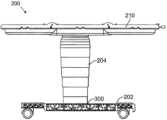
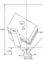
도 11은 대응하는 세트업 구조 링크장치(126)에 의해 지지된 다중 머니퓰레이터 아암(82)을 가진 환자측 카트(22)를 포함하는 예시적인 시스템의 개략도를 나타내고 있는데, 상기 세트업 구조 링크장치(126)의 아래에 수술대(200)가 배치되어 있다. 어떤 실시형태에서, 수술대(200)는 이 수술대가 환자측 카트(Patient Side Cart)와 별도로 배치가능하고, 종종 환자측 카트와 독립적으로 배치가능하도록 환자측 카트로부터 분리된 구조이다. 하지만, 어떤 다른 실시형태에서는, 본 명세서에 기술된 배치(localization) 및 자세 추정 방법이 별도로 배치가능한 수술대를 머니퓰레이터의 계산된 운동과 조율하여 제어되게 할 수 있어서, 상기 수술대가 별도로 배치가능한 것으로 남아 있지만 상기 운동이 상기 시스템에 의해 조정될 수 있기 때문에 더 이상 독립적으로 배치가능한 것으로 간주되지 않을 수 있다는 것을 알아야 한다. 다수의 실시례에서, 수술대(200)는 지지 베이스(202)에 부착된 지지 기둥(204)에 의해 지지된 수술대 환자 지지면(210)을 포함하고 있다. 상기 시스템은 기준 마커(300)를 더 포함하고 있고, 상기 기준 마커는, 환자측 카트의 머니퓰레이터와 수술대 환자 지지면(210) 사이의 공간적인 관계가 계산된 머니퓰레이터 운동 또는 명령된 수술대 운동에서 결정될 수 있고 이용될 수 있도록 상기 시스템이 수술대를 환자측 카트에 대해 합치되게 해 준다.11 shows a schematic diagram of an exemplary system comprising a patient-
도 12는 수술용 머니퓰레이터 시스템을 위한 예시적인 수술대(200)를 나타내고 있다. 상기 수술대(200)는, 작동시에 수술대 상부를 원하는 위치 및/또는 방향으로 이동시키는 하나 이상의 조인트(도시되어 있지 않음)를 포함할 수 있다. 상기 하나 이상의 조인트는 피구동 조인트(driven joint), 수동으로 관절운동되는 조인트(manually articulated joint), 또는 이들의 결합형태를 포함할 수 있다. 이러한 조인트는, 본 명세서에 기술된 것과 같은, 회전가능한 피벗 조인트뿐만 아니라 병진운동가능한 조인트, 예를 들면, 유압식 기계(hydraulics)를 포함할 수 있다. 상기 하나 이상의 조인트는, 필요에 따라, 환자측 보조자 또는 마취과 의사에 의해 조정될 수 있거나, 외과 의사 콘솔로부터 더 원격지의 사용자, 예를 들면, 내과 의사에 의해, 또는 자율적 알고리즘(autonomous algorithm)에 따르거나 환자 호흡 등과 같은 생리적 운동에 대한 보상 운동(compensating movement)과 같은 하나 이상의 계산된 운동에 따라 상기 시스템에 의해 조정되도록 구성될 수 있다.12 shows an exemplary operating table 200 for a surgical manipulator system. The operating table 200 may include one or more joints (not shown) that move the top of the operating table to a desired position and/or direction during operation. The one or more joints may include a driven joint, a manually articulated joint, or a combination thereof. Such joints may include rotatable pivot joints as described herein as well as translatable joints, such as hydraulics. The one or more joints may be adjusted, as needed, by a patient side assistant or an anesthesiologist, or by a user more remote from the surgeon's console, eg, a physician, or according to an autonomous algorithm or patient It may be configured to be adjusted by the system according to one or more calculated movements, such as compensating movements for physiological movements, such as breathing.
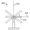
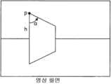
수술대(200)는 지지 베이스(202)로부터 수직으로 뻗은 지지 기둥(204)에 의해 지지된 수술대 환자 지지면(210)을 포함하고 있다. 통상적으로, 수술대(200)는 적어도 하나의 자유도를 따라 바람직하게는 복수의 자유도를 따라, 그리고 더욱 더 바람직하게는 6 자유도를 따라 배치가능하다. 도 12에 도시되어 있는 것과 같이, 예시적인 수술대(200)는 x-축, y-축을 따라서, 그리고 z-축을 따라서 수직방향으로 서로 직교하는 3개의 상이한 방향으로 병진이동될 수 있고, 또한 환자 지지면(210)의 길이를 따라서 뻗은 축(214)에 대해서 피벗운동할 수 있고, 환자 지지면(210)의 폭을 따라서 뻗은 축(216)에 대해서 피벗운동할 수 있고, 그리고 수직으로 뻗은 축(212)에 대해서 피벗운동할 수 있다. 이러한 피벗 운동은 도 13a 내지 도 13c에 도시되어 있다. 따라서, 예시적인 수술대(200)는 6 자유도를 따라 배치가능하다. 이러한 피벗축은 반드시 교차하는 것은 아니라는 것을 알 수 있다. 이러한 6 자유도에 의해 허용된 환자 지지면(210)의 다양한 위치 및/또는 방향은 환자의 원하는 위치, 방향 또는 경사도를 달성하기 위해서 초기 세트업 동안 이용될 수 있거나 어떤 이유로 환자를 다른 장소로 옮길 필요가 있는 수술 도중에 이용될 수 있다. 수술대가 동일한 방향으로 다양한 다른 축을 따라서 피벗 운동을 제공할 수 있도록, 피벗 운동은 도시된 특정 축을 중심에 두고 있을 필요는 없고, 이로 인해 수술대 상부가 수술대 상부나 수술대 상부에서 벗어난 다양한 위치에 대해서 피벗 운동을 제공할 수 있게 되는 것을 알 수 있다. 몇 가지 실시례에서는, 수술대가, 최소 침습 구멍 내로 기구가 삽입될 때 통과하는 캐뉼라나 그 근처에 있는 등각점(isocenter)에 대해서 상기와 같은 운동을 제공하도록 구성되어 있다.The operating table 200 includes an operating table
이러한 수술대의 고도의 구성가능성(configurability)은 환자를 배치시키는데 있어서 많은 장점과 융통성을 제공하는 반면에, 이러한 구성가능성은 머니퓰레이터 아암 및 결합된 공구의 운동을 계산하는데 있어서 추가적인 난제를 더 부과할 수 있다. 예를 들어, 수술대가 경사지게 배치되면, 공구 또는 이 공구를 지지하는 대응하는 머니퓰레이터의 특정 운동이 환자 지지면과 충돌할 수 있다. 이러한 충돌을 피하기 위해서 다양한 방법이 사용될 수 있지만, 머니퓰레이터의 운동이 수술대의 위치를 고려하기 위해 및/또는 수술 도중에 수술대의 이동 및/또는 재배치를 보상하기 위해서 계산될 수 있도록 환자측 카트의 머니퓰레이터에 대한 수술대의 위치가 결정되면 특히 유용하다. 이러한 결정을 가능하게 하기 위해서, 본 발명의 여러 실시형태에 따른 방법 및 시스템은 수술대와 환자측 카트 사이의 공간 관계가 필요에 따라 다양한 계산된 운동에서 결정되고 이용될 수 있도록 환자측 카트에 대한 수술대의 수술대 자세 추정(table pose estimate)을 제공한다. 다른 실시형태에서는, 본 발명의 방법이 특정 머니퓰레이터 조립체에 사용하기 위한 수술대를 확인하기 위해서 및/또는 특정 머니퓰레이터 조립체와 수술대 사이의 다양한 계산된 조정된 운동을 허용하기 위해 수술대와 교신하기 위해서 사용될 수 있다.While the high degree of configurability of these operating tables provides many advantages and flexibility in positioning the patient, this configurability can further impose additional challenges in calculating the motion of the manipulator arms and associated tools. . For example, if the operating table is disposed inclined, certain movements of the tool or the corresponding manipulator supporting the tool may collide with the patient support surface. A variety of methods can be used to avoid such collisions, but the operating table relative to the manipulators on the patient side cart so that the motion of the manipulators can be calculated to account for the position of the operating table and/or to compensate for movement and/or repositioning of the operating table during surgery. This is particularly useful when the location of To enable this determination, methods and systems in accordance with various embodiments of the present invention are provided such that the spatial relationship between the operating table and the patient-side cart can be determined and utilized in various computed motions as needed, with the operating table relative to the patient-side cart. Provides a table pose estimate. In other embodiments, the method of the present invention may be used to identify an operating table for use with a particular manipulator assembly and/or to communicate with an operating table to allow for various calculated coordinated movements between a particular manipulator assembly and the operating table. .
하나의 실시형태에서, 로봇과 수술대의 양자 모두가 복수의 자유도로 관절운동하는 물체이므로 로봇과 수술대의 상대적인 자세가 필요하다. 머니퓰레이터 조립체에 대한 수술대의 자세를 결정하는 것에 의해서, 수술대와 머니퓰레이터 조립체 사이의 조정된 운동을 실행시킴으로써 다양한 유리한 특징이 실현될 수 있다. 수술대와 머니퓰레이터 조립체 각각의 자유도(DOF)가 센서를 통하여 감지될 수 있기 때문에, 상기 구성요소의 임의의 두 부분 사이의 상대적인 자세의 결정은 충분하다. 하나의 실시형태에서, 상기 방법은 수술대의 베이스의 위치와 방향을 결정하고, 이것은 상기 시스템으로 하여 수술대와 머니퓰레이터 조립체 각각의 다양한 구성요소의 서로에 대한 상대적인 위치를 결정할 수 있게 해 준다.In one embodiment, the relative postures of the robot and the operating table are required since both the robot and the operating table are articulated objects with multiple degrees of freedom. By determining the posture of the operating table relative to the manipulator assembly, various advantageous features may be realized by effecting coordinated movement between the operating table and the manipulator assembly. Since the degree of freedom (DOF) of each of the operating table and manipulator assembly can be sensed via a sensor, it is sufficient to determine the relative pose between any two parts of the component. In one embodiment, the method determines the position and orientation of the base of the operating table, which enables the system to determine the relative positions of the various components of each of the operating table and manipulator assembly relative to each other.
어떤 실시례에서는, 포트들의 전체 운동을 최소화하기 위해서 수술대가 포트들의 중심(centroid) 둘레로 회전하도록 제어된다(등각점 개념(isocenter concept)). 이것은 다양한 특징, 특히 "포트 드래깅(port dragging)"에 대해서 유용하다. 포트 드래깅이 환자의 신체벽에 지나치게 큰 힘을 초래하면, 수술대의 움직임을 추종하기 위해 로봇 아암의 능동적인 구동이 필요하다. 로봇에 대한 (수술대 배치상태를 통하여)환자의 배치상태를 알면 로봇이 환자와의 잠재적인 충돌을 피하도록 자신의 제어를 최적화하는데 도움이 된다. 두 물체 사이의 상대적인 자세를 측정하는 여러 가지 방법이 있다. 우리가 바람직한 방법으로서 광학적인 해결방안(optical solution)을 선택하는데 몇 가지 제한이 있다In some embodiments, the operating table is controlled to rotate around the centroid of the ports to minimize overall motion of the ports (isocenter concept). This is useful for various features, especially "port dragging". If the port dragging causes too much force on the patient's body wall, active driving of the robot arm is required to follow the movement of the operating table. Knowing the patient's disposition to the robot (via operating table disposition) helps the robot optimize its control to avoid potential collisions with the patient. There are several ways to measure the relative pose between two objects. There are several limitations to our selection of an optical solution as our preferred method.
어떤 실시형태에서는, 본 발명의 방법이 종래의 머니퓰레이터 시스템보다 다양한 유리한 특징을 제공한다. 하나의 실시형태에서, 상기 방법은 수술용 로봇에 장착된 카메라와 수술대의 외측 표면상의 기준 마커(fiducial marker)를 이용하여 수술용 로봇과 수술대 사이의 6 DOF 3D 자세(병진운동과 회전운동)를 결정하는 것을 포함한다. 3D 자세는 기준 평면(ground plane)에서 3 DOF 2D 자세로 되고, 양쪽 구성요소는 공통의 기준 평면에 배치될 것으로 추정된다. 상기 기준 마커가 독립적으로 인식되고 식별될 수 있는 성분들로 세분될 수 있거나, 상기 기준 마커의 일부(subset)가 전체 마커에 대하여 인식되고 식별될 수 있다. 상기 기준 마커는 검사용 합계(check sum) 또는 리드-솔로몬 에러 체크 및 보정 계획(Reed-Solomon error checking and correction scheme)과 같은 리던던시(redundancy)를 내장하고 있다. 어떤 실시형태에 있어서, 상기 기준 마커는 자세 추정용 영상에 정확하게 배치될 수 있는 시각적인 특징을 포함하고 있다. 상기 기준 마커는 데이터 매트릭스 코드(data matrix code)로 될 수 있는 독특한 다중 2D 바코드로 이루어질 수 있다. 상기 기준 마커는 수직으로 배향된 바를 가진 독특한 다중 1D 바코드로 이루어질 수 있다. 다른 실시형태에서는, 상기 기준 마커가 깜박이는 방식(예를 들면, 모스 부호)의 다중 단일점 발광 장치(multiple single point light emitting device)로 이루어질 수 있고, 상기 장치의 독특한 식별자(identifier)를 형성하기 위해 색채와 결합될 수도 있다.In some embodiments, the method of the present invention provides a number of advantageous features over conventional manipulator systems. In one embodiment, the method uses a camera mounted on the surgical robot and a fiducial marker on the outer surface of the operating table to determine a 6 DOF 3D posture (translational and rotational motion) between the surgical robot and the operating table. includes deciding It is assumed that the 3D pose will be a 3 DOF 2D pose in the ground plane, and both components will be placed on a common ground plane. The fiducial markers can be subdivided into components that can be independently recognized and identified, or a subset of the fiducial markers can be recognized and identified relative to the entire marker. The fiducial marker has built-in redundancy such as a check sum or a Reed-Solomon error checking and correction scheme. In some embodiments, the fiducial marker includes a visual feature that can be accurately placed in an image for position estimation. The fiducial marker may consist of a unique multiple 2D barcode that may be a data matrix code. The fiducial markers may consist of unique multiple 1D barcodes with vertically oriented bars. In another embodiment, the fiducial marker may consist of multiple single point light emitting devices in a blinking manner (e.g., Morse code), forming a unique identifier for the device. It can also be combined with color for
여러 실시례가 본 명세서에 기술된 임의의 기준 마커의 여러 실시형태를 포함하는 하나 이상의 마커를 포함할 수 있다는 것을 알 수 있다. 예를 들면, 수술대가 발광 장치, RFID 태그, 또는 본 명세서에 기술된 임의의 실시형태와 결합하여1D 바코드, 2D 바코드 또는 3D 바코드를 포함하는 하나 이상의 마커를 포함할 수 있다. 추가적으로, 이러한 마커는 하나 이상의 다른 외부 장치와 결합된 하나 이상의 대응하는 센서에 의해 각각의 마커를 감지할 수 있게 하기 위해서 수술대의 다양한 다른 장소에 포함될 수 있다. 머니퓰레이터 조립체에 대해 수술대를 배치시키는 방법은, 비제한적인 예로서, 다양한 산업용 로봇 사용예를 포함하는 다양한 다른 사용예뿐만 아니라, 비-수술적인 사용예, 예를 들면, 원격 수술 시스템의 시뮬레이션, 테스트 및/또는 세트업에 적용되는 것 또한 알 수 있다.It will be appreciated that various embodiments may include one or more markers including multiple embodiments of any of the fiducial markers described herein. For example, an operating table may include a light emitting device, an RFID tag, or one or more markers including 1D barcodes, 2D barcodes, or 3D barcodes in combination with any of the embodiments described herein. Additionally, these markers may be included in various other locations on the operating table to enable each marker to be sensed by one or more corresponding sensors coupled with one or more other external devices. The method of positioning the operating table relative to the manipulator assembly can be used for non-surgical uses, such as simulation, testing of telesurgical systems, as well as a variety of other uses, including, but not limited to, various industrial robotic uses. and/or set-up.
어떤 다른 실시형태에서는, 상기 기준 마커가 특정 머니퓰레이터 조립체와 함께 사용되는 수술대의 종류, 모델, 일련 번호를 식별하기 위해서 사용될 수 있다. 상기 기준 마커 패턴은 각각의 수술대에 대해서 독특한 식별자를 포함할 수 있다. 상기 소프트웨어는 상기 영상에서 기준 마커를 검출하고, 시각적인 특징의 위치를 추출하도록 구성될 수 있다. 기준 마커의 독특한 식별자료는 기준 마커의 알려진 3D 위치를 사용하는 것에 의해서 상응관계가 수립되게 하였다. 대응하는 3D 관측자료 및 2D 관측자료는 카메라에 대한 수술대의 3D 자세를 계산하기 위해서 사용된다. 어떤 실시례에서는, 복수의 수술용 로봇 또는 디스조인트 수술용 로봇 구성요소(disjoint surgical robot component) 각각이 카메라를 구비하고 있다. 하나의 실시형태에서는, 카메라들로 하여 외측 표면에 기준 마커를 가진 공통의 수술대를 관찰하게 함으로써 상대적인 자세가 계산된다. 카메라들은 공통 시야(common view)를 가질 것을 요하지 않는다는 것을 알 수 있다. 이러한 방법의 많은 장점들 중의 하나는, 다수의 실시례에서, 배치를 위해서 머니퓰레이터 조립체와 수술대 사이의 물리적인 연결이 필요하지 않다는 것이다. 시선이 머니퓰레이터와 결합된 센서와 수술대의 적어도 하나의 마커 패턴 사이에 유지되는 한, 배치가 외부 환경(예를 들면 EMI)에 의해 영향을 받지 않는다. 몇몇 실시형태에서는, 일단 배치가 이루어지면, 수술대를 다른 장소로 옮기지 않는 한 시선이 유지될 필요가 없다. 다른 실시형태에서는, 하나 이상의 기준 마커를 이용하여 수술대를 재배치할 것을 요하지 않고 배치 후 수술대 자세에서의 모든 변화가 파악되도록 수술대 상부가 위치되는 이동가능한 지지 구조가 머니퓰레이터 조립체와 무선으로 교신한다.In some other embodiments, the fiducial marker may be used to identify the type, model, and serial number of an operating table used with a particular manipulator assembly. The fiducial marker pattern may include a unique identifier for each operating table. The software may be configured to detect fiducial markers in the image and extract locations of visual features. The unique identification of the fiducial marker allowed correspondence to be established by using the known 3D location of the fiducial marker. Corresponding 3D observation data and 2D observation data are used to calculate the 3D posture of the operating table relative to the camera. In some embodiments, each of the plurality of surgical robots or disjoint surgical robot components includes a camera. In one embodiment, the relative pose is calculated by having the cameras view a common operating table with fiducial markers on the outer surface. It can be seen that the cameras are not required to have a common view. One of the many advantages of this method is that, in many embodiments, no physical connection between the manipulator assembly and the operating table is required for deployment. As long as the line of sight is maintained between the sensor coupled with the manipulator and the at least one marker pattern on the operating table, the placement is not affected by the external environment (e.g. EMI). In some embodiments, once positioned, line of sight need not be maintained unless the operating table is relocated. In another embodiment, the movable support structure on which the operating table top is positioned wirelessly communicates with the manipulator assembly so that any change in operating table posture is captured after deployment without requiring repositioning of the operating table using one or more fiducial markers.
도 14a 및 도 14b는 본 발명의 실시형태에 따른 예시적인 수술대를 나타내고 있다. 도 14a 및 도 14b는 각각 환자 지지면(210), 수직 지지 기둥(204) 그리고 기준 마커(300)를 가진 이동가능한 지지 베이스(202)를 가지고 있는 배치가능한 수술대(200)를 나타내고 있다. 하나의 실시형태에서, 상기 베이스는 금속이고 상기 기준 마커는 수술대에, 예를 들면 수술대 상부 기판(table top substrate)의 맨 아래 부분이나 측면에 레이저 에칭처리, 새기기, 또는 돋을새김되어 있다. 기준 마커를 만드는 이러한 방법은, 다양한 다른 종류의 마커와는 대조적으로, 쉽게 살균할 수 있기 때문에 유리하다. 추가적으로, 이러한 마커는 쉽게 제거되지 않으며, 이러한 마커 특정 머니퓰레이터 조립체용 수술대의 제대로 된 식별을 보장하는데 사용될 수 있다.14A and 14B show an exemplary operating table according to an embodiment of the present invention. 14A and 14B show a deployable operating table 200 having a
도 15는 도 14b에 도시된 기준 마커의 상세한 예를 나타나고 있다. 이러한 마커는 머니퓰레이터 조립체와 결합된 센서(통상적으로, 머니퓰레이터 조립체의 베이스에 배치된 센서 또는 카메라)로부터의 마커의 거리가 결정될 수 있도록 3D 특징부를 포함할 수도 있다. 추가적으로, 상기 거리는, 센서 판독기의 판독 구역(도 15에 원들로 표시되어 있음) 내에서 판독되는 마커의 크기와 양이 얼마인지에 의해서 결정될 수도 있다. 하나의 실시형태에서, 상기 마커는 머니퓰레이터 조립체에 대한 서지컬 베이스(surgical base)의 상대적인 위치 및/또는 방향을 결정하는데 적합한 임의의 마커 유형이 될 수 있다. 통상적으로, 상기 마커 체계(scheme)와 센서 모듈은 지면에 있는 물체에 부착된 마커를 이용하여 지면에 있는 물체의 2D 자세를 추정하도록 구성되어 있다. 하나의 실시형태에서, 상기 마커는, 바코드에 의해서 제공된 것과 같은, 에러 체크 리던던시(error checking redundancy)를 포함하고 있다. 청소용 화학물질을 견딜 수 있는 내구성이 있는 라벨 물질(label material)이 바람직하다. 마커는 기계 판독가능 마커의 일부로서 독특한 테이블 ID(unique table ID)로 구성될 수 있다. 어떤 실시례에서는, 상기 마커가 대체로 높이와 폭이 2cm 내지 12cm이고 수술대의 베이스의 표면을 따라서, 종종 전체 수술대 둘레에 일련의 마커를 포함할 수 있다. 하나의 실시형태에서, 상기 마커는, 상기 마커가 다양한 상이한 위치 및/또는 방향에서 머니퓰레이터 조립체의 베이스에 있는 센서에 의해 판독될 수 있게 60도 이상의 수평방향의 시야(horizontal field of view) 내에서 상기 마커가 보이도록 구성되어 있다.이러한 실시형태는 도 16의 개략도를 참고하여 보다 상세하게 이해될 수 있다.FIG. 15 shows a detailed example of the fiducial marker shown in FIG. 14B. Such markers may include 3D features so that the marker's distance from a sensor associated with the manipulator assembly (typically a sensor or camera disposed at the base of the manipulator assembly) can be determined. Additionally, the distance may be determined by the size and amount of markers being read within the reading area of the sensor reader (indicated by circles in Fig. 15). In one embodiment, the marker may be any type of marker suitable for determining the position and/or orientation of a surgical base relative to the manipulator assembly. Typically, the marker scheme and sensor module are configured to estimate the 2D pose of an object on the ground using a marker attached to the object on the ground. In one embodiment, the marker includes error checking redundancy, such as provided by a barcode. A durable label material that can withstand cleaning chemicals is desirable. A marker may consist of a unique table ID as part of a machine readable marker. In some embodiments, the markers are generally between 2 cm and 12 cm in height and width and may include a series of markers along the surface of the base of the operating table, often around the entire operating table. In one embodiment, the marker is positioned within a horizontal field of view of at least 60 degrees such that the marker can be read by a sensor at the base of the manipulator assembly at a variety of different locations and/or orientations. It is configured so that the marker is visible.This embodiment can be understood in more detail with reference to the schematic diagram of FIG. 16 .
하나의 실시형태에서, 상기 마커와 센서는 아래의 사항:In one embodiment, the markers and sensors:
* 센서 모듈은 센서와 물체의 앞면 사이의 거리가 5cm 내지 100cm의 범위에 있으면 자세 추정을 수행한다. 센서 모듈은 물체가 센서의 시야의 중심에 있거나 센서의 시야의 중심에서 벗어나 있을 때 작용하도록 구성될 수 있는 것을 주의해야 한다.* The sensor module performs posture estimation when the distance between the sensor and the front of the object is in the range of 5 cm to 100 cm. It should be noted that the sensor module may be configured to act when an object is either in the center of the sensor's field of view or out of the center of the sensor's field of view.
* 센서 모듈는 확장된 범위에서 작용한다. 센서 모듈은 물체가 센서에 대해 임의의 각도를 이룰 때 자세 추정을 수행하도록 구성되어 있다.* The sensor module operates in an extended range. The sensor module is configured to perform pose estimation when an object forms an arbitrary angle with respect to the sensor.
의 전부 또는 일부를 포함하는 다양한 운동 범위 고려사항에 따라 구성되어 있다.It is structured according to various range of motion considerations that include all or part of the
하나의 실시형태에서, 상기 마커와 센서는 아래의 사항:In one embodiment, the markers and sensors:
* 외부 환경은 매우 약한 빛(5 lux)에서부터 밝은 수술실 조명(2000 lux)까지 될 수 있다.* The external environment can range from very weak light (5 lux) to bright operating room lighting (2000 lux).
* 필요하다면, 가외의 조명, 아마도 근적외선(near-IR)이 센서에 가까이 배치될 수 있다.* If needed, extra illumination, possibly near-IR, can be placed close to the sensor.
* 상기 가외의 조명은 영상 데이터 수집을 수행할 때, 필요에 따라, 작동하도록 구성될 수 있다.* The extra lights can be configured to operate, as needed, when performing image data collection.
의 전부 또는 일부를 포함하는 다양한 조명 고려사항에 따라 구성되어 있다.It is configured according to various lighting considerations, including all or part of.
수술실 수술대 자세 추정Operating room operating table posture estimation
하나의 실시형태에서, 이러한 방법으로부터 이익을 얻는 머니퓰레이터 조립체의 한 가지 두드러지는 특징은 수술하는 동안 결합해제(undocking)와 재결합(re-docking)없이 환자 테이블를 이동시키는 능력이다. 내부 수술대 움직임(intra-operative table motion)을 수용하기 위해, 3D에서의 한 지점에 대해서 피벗운동하는 수술실(OR) 수술대가 사용될 수 있다. 몇 가지 실시례에서, 피벗운동 중심은 모든 포트들의 전체 변위가 최소화되도록 모든 포트들의 중심(centroid)과 일치한다. 이것은 환자측 카트(PSC)와 수술실 수술대의 상대적인 자세가 알려질으로 필요로 할 수 있다. 환자측 카트(PSC)와 수술실 수술대의 양자 모두에 대해 모든 기구학 정보(full kinematics information)를 이용할 수 있기 때문에, 환자측 카트(PSC)의 임의의 부분과 수술실 수술대의 임의의 부분 사이의 자세는 충분하다. 이러한 방법은 수술실 수술대와 환자측 카트(PSC)의 사이에 기계적인 링크가 없다는 것; 수술실 수술대와 환자측 카트(PSC)의 사이에 케이블이 없다는 것 중의 일부 또는 전부를 포함하여, 종래의 마커 판독 기술 또는 배치 방법과 관련될 수 있는 다양한 문제를 처리한다. 이러한 방법은 빛을 필요로 하지 않는 로봇 수술과 관련된 낮은 조명, 특히 밝은 일반적인 수술실, 가능한 간섭, 소작 소음(cautery noise), IR 링크 및/또는 RF 링크의 존재를 포함하여, 수술실 환경과 관련된 여러가지 곤란한 점들을 해결한다.In one embodiment, one distinguishing feature of the manipulator assembly that benefits from this method is the ability to move the patient table during surgery without undocking and re-docking. To accommodate intra-operative table motion, an OR operating table may be used that pivots about a point in 3D. In some embodiments, the pivot center of motion coincides with the centroid of all ports such that the total displacement of all ports is minimized. This may require the relative position of the patient side cart (PSC) and operating table to be known. Since full kinematics information is available for both the patient side cart (PSC) and the operating table, the pose between any part of the patient side cart (PSC) and any part of the operating table is sufficient. This method is characterized by the absence of a mechanical link between the operating room operating table and the patient side cart (PSC); Addresses a variety of problems that may be associated with conventional marker reading techniques or placement methods, including some or all of the absence of cables between the operating room operating table and the patient side cart (PSC). This method suffers from a number of difficulties associated with the operating room environment, including the low lighting associated with robotic surgery that does not require light, especially a bright typical operating room, possible interference, cautery noise, and the presence of IR links and/or RF links. solve the dots
하나의 실시형태에서, 상기 마커와 센서는 충분한 정확도를 제공하도록 구성되어 있다. 몇 가지 실시례에서, 이 정확도 요건은 수술대의 중심이 +/-1Omm 내에서 측정되는 것이고, 이 요건은 대체로 캐뉼라의 크기로부터 도출된다. 오차가 영이 경우에도, 머니퓰레이터가 각각의 포트에서 약간의 변위를 가지고 있기 때문에(예를 들면, 피벗운동 중심이 모든 포트들의 중심(centroid)이기 때문에); 따라서, 보다 큰 오차가 용인될 수 있다.In one embodiment, the markers and sensors are configured to provide sufficient accuracy. In some embodiments, this accuracy requirement is that the center of the operating table is measured to within +/- 10 mm, and this requirement is generally derived from the size of the cannula. Even when the error is zero, since the manipulator has some displacement at each port (eg, because the pivoting center of motion is the centroid of all ports); Thus, larger errors can be tolerated.
다른 실시형태에서는, 센서 모듈이 환자측 카트(PSC)의 베이스에 할당된 공간에 끼워 맞추어질 필요가 있다. 몇 가지 실시례에서, 머니퓰레이터 조립체의 베이스에서 센서 모듈에 대해 할당된 공간은 약 3" x 3" x 5"인 반면에, 광학적 창문(optical window)으로부터 최전방 표면까지의 거리는 약 2"이다. 도 17은 머니퓰레이터 조립체의 베이스 내에서의 센서 카메라의 한 가지 가능한 배치상태를 나타내고 있다. 몇 가지 실시례에서는, 센서 또는 카메라 장착부에 충격 흡수부가 포함되어 있다.In other embodiments, the sensor module needs to fit into the space allocated to the base of the patient side cart (PSC). In some embodiments, the space allocated for the sensor module at the base of the manipulator assembly is about 3" x 3" x 5", while the distance from the optical window to the foremost surface is about 2". Figure 17 shows one possible placement of the sensor camera within the base of the manipulator assembly. In some embodiments, a shock absorber is included in the sensor or camera mount.
다른 실시형태에서는, 센서 및 마커 구성가 수술대의 다양한 위치 및/또는 방향을 허용하는 수술대와 머니퓰레이터 조립체 사이의 충분한 작동 거리를 허용하기 위해서 판독되도록 구성되어 있다. 예를 들면, 상기 마커와 센서는 상기 마커가 60도에 가까운 수평방향 시야 내에서 판독될 수 있고 상기 마커를 판독하는 작동 거리가 1인치 내지 2피트 이상일 수 있도록 구성될 수 있다. 특정 수술을 위해서 필요할 수 있을 때 수술대가 완전히 회전할 수 있도록 수술대는 지지 베이스의 각 측면에 마커를 포함할 수도 있다.In other embodiments, the sensor and marker arrangements are configured to be read to allow for sufficient working distance between the operating table and the manipulator assembly to allow for various positions and/or orientations of the operating table. For example, the markers and sensors can be configured such that the markers can be read within a horizontal field of view close to 60 degrees and the working distance to read the markers can be 1 inch to 2 feet or more. The operating table may include markers on each side of the support base to allow full rotation of the operating table as may be necessary for a particular operation.
어떤 실시형태에 있어서, 상기 마커와 센서는 전자기적 트래킹(electro-magnetic tracking), 광학적 트래킹(optical tracking), 레이저 기반 형상 센서(laser based, shape sensor), 초음파 수단, 또는 이들의 임의의 결합형태 중의 일부 또는 전부로 하나 이상의 마커를 추적하도록 구성될 수 있다. 하지만, 이러한 접근방식들 중의 어떤 것과 관련된 단점으로 인해, 상기 방법은 본 명세서에 기술되어 있는 것과 같이 자세 추정을 수행하기 위해 마커의 광학적인 트래킹을 통상적으로 활용한다. 광학적 트래킹의 한 가지 장점은 눈에 보이지 않는 간섭(예를 들면, 전자기(EM) 간섭)에 의해 영향을 받지 않는다는 것이다. 기준 마커가 보일 필요가 있기 때문에 시선 문제는 불리한 면이다. 하지만, EM 간섭과 다르게, 이것은 사용자가 수정하는 것을 이해하기가 훨씬 더 쉽다(예를 들면, 카메라와 마커 사이의 쓰레기통을 치우는 것). 광학적 트래킹의 기본 원리는 영상 관측자료에 의해서 알려진 기하학적 구조를 가진 물체 또는 기준 마커의 자세를 계산하는 것이다. 다른 실시형태에서는, 단안 카메라 또는 한 쌍의 스테레오 카메라(stereo camera)가 사용될 수 있다.In some embodiments, the markers and sensors are electro-magnetic tracking, optical tracking, laser based (shape sensor), ultrasonic means, or any combination thereof. Some or all of them may be configured to track one or more markers. However, due to drawbacks associated with any of these approaches, the method typically utilizes optical tracking of a marker to perform pose estimation as described herein. One advantage of optical tracking is that it is not affected by invisible interference (e.g., electromagnetic (EM) interference). The line of sight problem is on the downside since the fiducial marker needs to be visible. However, unlike EM interference, it is much easier to understand what the user is modifying (eg, clearing the trash can between the camera and the marker). The basic principle of optical tracking is to calculate the pose of an object or fiducial marker with a known geometric structure from image observations. In other embodiments, a monocular camera or a pair of stereo cameras may be used.
하나의 실시형태에서, 다중 수동형 역반사 볼(multiple passive retro-reflective ball) 또는 능동형 블링킹 LED(active blinking LED)가 기하학적으로 독특한 구성을 형성한다. 하나의 실시형태에서, 기준 마커는 2D 바코드를 포함하고 있다. 임의의 2D 바코드는 판독기가 바코드의 몇 개(이상적으로는 >= 4)의 기준 지점의 영상 좌표를 제공할 수 있는 한 마커로서 사용될 수 있어야 한다. 다른 실시형태에서는, 능동형 포인트 마커(active point marker)가 사용될 수 있다. 다중 능동형 포인트 마커(예를 들면, LEDs)가 수술대 베이스의 주변부 둘레에 배치되어 있다. 이들의 깜박이는 패턴은 용이하게 자가-식별가능(self-identifiable)하도록 독특하다. 3개 이상의 포인트가 시야에 보이면, 자세를 계산할 수 있다. 능동형 포인트 마커는 발광형 기준 마커이기 때문에, 수동형 마커보다 대비도(contrast)가 높고 환자측 카트(PSC)에 광원이 필요없다. 조명을 위한 전체 전력 소비는 훨씬 더 낮다. 수동형 마커와 달리, 능동형 포인트 마커는 마커에 전력이 공급되고 제어될 것을 요하고, 이것은 능동형 포인트 마커를 덜 바람직하게 한다. 모든 기준 마커가 동일한 레벨에 있는 경우 ld CCD 센서를 사용할 수 있다.In one embodiment, multiple passive retro-reflective balls or active blinking LEDs form a geometrically unique configuration. In one embodiment, the fiducial marker comprises a 2D barcode. Any 2D barcode should be usable as a marker as long as the reader can provide the image coordinates of several (ideally >= 4) reference points in the barcode. In other embodiments, active point markers may be used. Multiple active point markers (eg LEDs) are placed around the periphery of the operating table base. Their blinking patterns are unique so that they are easily self-identifiable. If 3 or more points are in view, the pose can be calculated. Since active point markers are emissive fiducial markers, they have higher contrast than passive markers and do not require a light source in the patient side cart (PSC). Overall power consumption for lighting is much lower. Unlike passive markers, active point markers require the marker to be powered and controlled, which makes active point markers less desirable. An ld CCD sensor can be used if all fiducial markers are at the same level.
광학적 자세 추정Optical pose estimation
도 18a 및 도 18b는 광학적 트래킹에 의한 자세 추정법을 예시하는 그림을 나타내고 있다. 상기 그림은 카메라 중심이 패턴의 중심에 있고 카메라가 수평으로 향하는 단순화된 구성에서 자세 추정의 원리를 나타내고 있다. 영상의 패턴은 수평선에 의해 거울상이 되어야 하므로 상부 부분만 고려한다. p의x 좌표는 평면도에서 광선의 각도를 결정한다. p(h)의 좌표는 거리(d)를 결정한다. 마커의 3D 회전은 사다리꼴 변(trapezoid side)의 영상 회전과 1:1 매핑(mapping)을 가진다. 상기 영상에서 이러한 세 개의 양은 평면도에서 3 DOF 자세를 완전히 결정할 수 있다. 이 예에는, 8개의 측정값이 있다(영상에서 4 좌표). 이것은 과도하게 결정된 시스템(over-determined system)이고 상기 측정값의 나머지는 자세 추정을 보다 정확하게 하기 위해서 사용된다.18A and 18B show pictures illustrating a posture estimation method by optical tracking. The above figure shows the principle of attitude estimation in a simplified configuration in which the camera center is at the center of the pattern and the camera is horizontally oriented. Since the pattern of the image must be mirrored by the horizontal line, only the upper part is considered. Thex coordinate of p determines the angle of the ray in plan view. The coordinates of p(h) determine the distance d. The 3D rotation of the marker has a 1:1 mapping with the image rotation of the trapezoid side. In the image above, these three quantities can completely determine the 3 DOF attitude in plan view. In this example, there are 8 measurements (4 coordinates in the image). This is an over-determined system and the rest of the measurements are used to make the attitude estimate more accurate.
상기 추정을 위한 방정식은 아래의 식:The equation for the estimation is:
d = (H*t)Ihd = (H*t)I h
이고, 상기 식에서 H는 마커의 물리적 절반 높이(physical half height)이고, f는 화소에서의 초점 거리(f = (resolution/2)Itan(fovl2))이다. h와 d 사이의 관계가 비선형적이라는 것은 명확하다. (비교예로서, 오버헤드 카메라(overhead camera)는 곧은 선형 관계(straight linear relationship)와 영상 해상도의 최대화된 활용을 제공한다). 깊이 해상도(depth resolution)는 h에 대한 d의 도함수(derivative)에 의해 계산될 수 있다., where H is the physical half height of the marker, and f is the focal length at the pixel (f = (resolution/2)I tan(fovl2)). It is clear that the relationship between h and d is non-linear. (As a comparative example, an overhead camera provides a straight linear relationship and maximized utilization of image resolution). Depth resolution can be calculated by the derivative of d with respect to h.
d' = -H*f/(h"2)d' = -H*f/(h"2)
도19a 및 도 19b의 그림은 깊이 해상도를 나타낸다. 이 예에서, 1 화소의 오차의 영상은 600mm(-2')의 거리에서 10mm의 거리 오차로 바뀌고, 상기 정확도 요건을 대략적으로 만족시킨다. 몇 가지 실시례에서, 자세 추정은 조정된 단안 카메라(calibrated monocular camera)로부터 알려진 기학학적 구조로 물체의 3D 자세(3 병진운동과 3 회전운동)를 결정하는 것을 포함하고 있다. 상기 모듈도 공구 트래킹(tool tracking)에 있을 수 있다. 다른 실시형태에서는, 3 DOF(2x 병진운동과 1 x 회전운동)만 추정할 필요가 있도록 자세 추정이 평면(예를 들면, 기준 평면)에서 실행된다. 이러한 경우에, 적어도 두 개의 옵션:do19a and 19b show the depth resolution. In this example, an image with an error of 1 pixel turns into a distance error of 10 mm at a distance of 600 mm (-2'), which approximately satisfies the above accuracy requirement. In some embodiments, pose estimation includes determining the 3D pose (3 translations and 3 rotations) of an object with known geometry from a calibrated monocular camera. The module may also be in tool tracking. In another embodiment, pose estimation is performed in a plane (eg, reference plane) so that only 3 DOFs (2x translation and 1x rotation) need be estimated. In this case, at least two options:


이 있다.there is
몇 가지 실시례에서, 기준 마커가 수술대의 베이스를 둘러싸서 완전히 덮도록 구성되어 있다. 수술 도중에 적어도 하나의 마커가 보일 가능성을 최대화하기 위해서 모든 구역이 마커로 덮힐 수 있다. 크기는 작업 범위의 근단부와 원단부 양자의 제한사항에 의해 결정될 수 있다. 바코드의 폭 높이 비율(width height ratio)은 회전으로 인해 수평 방향에서의 원근법적 왜곡(foreshortening)이 수직 방향에서보다 더 크다는 사실 때문에 1보다 더 크게 되어 있다. 보다 정량적인 분석이 아래에 제공되어 있다. 시점(viewpoint)이 알려져 있지 않은 경우에 자가-식별가능 하위 마커(self-identifiable sub-marker)가 부분적인 폐쇄를 처리하기 위한 한 가지 방법이다. 각각의 하위 마커는 독특한 ID를 가지고 있고 상기 모델과 관련될 수 있다. 한 개의 하위 마커는 자세 추정을 위한 충분한 제한을 제공하지만 더 많은 하위 마커는 정확도를 향상시킨다.In some embodiments, a fiducial marker is configured to surround and completely cover the base of the operating table. All areas may be covered with markers to maximize the likelihood of at least one marker being visible during surgery. The size can be determined by the limitations of both the near and far ends of the working range. The barcode's width-height ratio is greater than 1 due to the fact that the foreshortening in the horizontal direction due to rotation is greater than in the vertical direction. A more quantitative analysis is provided below. A self-identifiable sub-marker is one way to handle partial closure when the viewpoint is unknown. Each sub-marker has a unique ID and can be associated with the model. One sub-marker provides sufficient constraint for posture estimation, but more sub-markers improve the accuracy.
하나의 실시형태에서, 바코드의 크기는 두 가지 요소를 포함하고 있다. 최대 거리와 최대 회전 각도에서 바코드를 검출할 수 있도록 하한이 필요하다. 최소 작동 거리에서 적어도 전체 패턴이 보이는 것을 확실하게 하기 위해서 상한이 필요하다. 다른 실시형태에서는, 상기 마커와 센서가 마커의 시선을 유지시키도록 구성되어 있다. 도 11b를 참고하여 알 수 있는 것과 같이, 수술대의 대부분이 시야에서 감추어지도록 수술 도중에 수술대는 천으로 덮혀 있다. 따라서, 수술대가 천으로 덮혀 있을 때 기준 마커와 센서 사이의 시선이 명확하게 유지되도록 기준 마커와 센서를 구성하는 것이 특히 유용하다. 이것을 달성하는 한 가지 수단은 수술대의 베이스에 기준 마커를 배치시키고 머니퓰레이터 조립체의 베이스 내에 센서를 배치시키는 것이다. 이론상으로 상기 시스템이 결합된 후에는 사람이나 장비가 두 부분 사이에 있으면 안된다는 것을 주의해야 한다. 대체 실시형태는 적외선, RFID 태그 또는 천 재료(draping material) 또는 다른 이러한 장애물을 잠재적으로 투과할 수 있는 다양한 다른 수단을 포함할 수 있다. 한 가지 대체 실시형태는 시선이 한 센서에 의해 차단되면, 다른 센서가 사용될 수 있도록 복수의 센서를 포함하는 것이다.In one embodiment, the size of the barcode includes two factors. A lower limit is required so that the barcode can be detected at the maximum distance and maximum angle of rotation. The upper limit is needed to ensure that at least the entire pattern is visible at the minimum working distance. In another embodiment, the marker and sensor are configured to maintain line of sight of the marker. As can be seen with reference to FIG. 11B , the operating table is covered with a cloth during surgery so that most of the operating table is hidden from view. Accordingly, it is particularly useful to configure the fiducial marker and sensor such that a clear line of sight between the fiducial marker and sensor is maintained when the operating table is covered with a cloth. One means of accomplishing this is to place a fiducial marker in the base of the operating table and place a sensor in the base of the manipulator assembly. It should be noted that in theory, once the system has been joined, no persons or equipment should be between the two parts. Alternate embodiments may include infrared light, RFID tags or various other means potentially capable of penetrating draping material or other such obstructions. One alternative embodiment is to include multiple sensors so that if the line of sight is blocked by one sensor, another sensor can be used.
도 21 및 도 22는 카메라와 바코드 판독기를 기존의 원격 조종 수술 머니퓰레이터 시스템에 통합하여 사용될 수 있는 두 가지 대체 접근방식을 나타내고 있다. 하나의 실시형태에서, 카메라 프레임에서의 자세가 유용하게 되도록 환자측 카트(PSC) 프레임으로 변형될 필요가 있다. 이것은 연쇄적인 2가지 변형: 즉, 카메라 내부로부터 카메라 외함(enclosure)으로의 변형; 그리고 카메라 외함으로부터 환자측 카트(PSC)로의 변형을 포함할 수 있다. 하나의 실시형태에서, 조정(calibration)이 불필요하도록 두 번째 것이 정확하게 될 수 있으면 특히 유용하다. 이것은 카메라를 교체할 필요가 있는 경우에, 시야 조정(field calibration)이 필요하지 않도록 모든 조정이 공장에서 이루어질 수 있게 한다.21 and 22 show two alternative approaches that can be used by integrating a camera and barcode reader into an existing remotely operated surgical manipulator system. In one embodiment, the pose in the camera frame needs to be transformed into a patient side cart (PSC) frame to be useful. This cascades two transformations: from inside the camera to the camera enclosure; and transformation from a camera enclosure to a patient side cart (PSC). In one embodiment, it is particularly useful if the second one can be made accurate so that no calibration is necessary. This allows all adjustments to be made at the factory so that in case the camera needs to be replaced, no field calibration is required.
도 23 및 도 24는 본 발명의 여러 실시형태에 따른 예시적인 방법을 나타내고 있다. 하나의 예에서, 자세 추정의 방법은 배치가능한 수술대의 6DOF 3D 자세를 기준 평면상의 3DOF 2D 자세로 변환시키는 것; 머니퓰레이터 조립체와 결합된 카메라로 수술대의 베이스에 있는 마커를 판독하는 것; 기준 마커의 판독에 기초하여 기준 평면상에서 머니퓰레이터 조립체에 대해 수술대를 배치시키는 것; 그리고 기준 평면 상에서의 머니퓰레이터 조립체에 대한 수술대의 베이스의 배치에 기초하여 머니퓰레이터 조립체에 대해 수술대의 3D 자세를 추정하는 것을 포함하고 있다. 일부 방법은, 카메라의 시각적인 영상 내에서 수술대의 위치를 추출하는 것과 카메라 시야에 대하여 수술대의 표시 또는 지시를 제공하는 것을 더 포함하고 있다. 다른 예에서, 상기 방법은 머니퓰레이터 조립체와 결합된 카메라로 수술대의 베이스에 있는 마커를 판독하는 것, 마커의 판독에 기초하여 수술대의 종류, 모델, 또는 수술대의 제조회사를 식별하는 것을 포함하고 있다. 일부 방법은 수술대와 머니퓰레이터 조립체의 양립가능성 측면(compatibility aspect)을 체크하는 것 및/또는 수술대와 함께 머니퓰레이터 조립체를 사용하는 것에 대한 허락을 승인하는 것을 더 포함하고 있다. 이러한 방법은 수술대 자세 추정의 계산 및/또는 수술대와 머니퓰레이터 조립체 사이의 조정 운동(coordinate movement)의 계산을 위해 수술대의 종류, 모델, 또는 수술대의 제조회사를 출력하는 것을 포함할 수 있다.23 and 24 show exemplary methods in accordance with various embodiments of the present invention. In one example, a method of pose estimation may include converting a 6DOF 3D pose of a deployable operating table to a 3DOF 2D pose on a reference plane; reading markers on the base of the operating table with a camera coupled to the manipulator assembly; positioning the operating table relative to the manipulator assembly on a reference plane based on the reading of the reference marker; and estimating a 3D pose of the operating table relative to the manipulator assembly based on the placement of the base of the operating table relative to the manipulator assembly on the reference plane. Some methods further include extracting the position of the operating table within the camera's visual image and providing an indication or indication of the operating table relative to the camera's field of view. In another example, the method includes reading a marker on the base of the operating table with a camera coupled to the manipulator assembly, and identifying the type, model, or manufacturer of the operating table based on the reading of the marker. Some methods further include checking compatibility aspects of the operating table and manipulator assembly and/or granting permission to use the manipulator assembly with the operating table. Such methods may include outputting the type, model, or manufacturer of the operating table for calculation of an operating table posture estimate and/or calculation of coordinated movement between the operating table and manipulator assembly.
다른 다양한 변형이 본 발명의 기술사상 내에 있다. 따라서, 본 발명은 다양한 수정형태와 대체 실시형태의 구조로 될 수 있으며, 이들의 예시된 특정 실시례가 도면에 도시되어 있으며 위에 상세하게 설명되어 있다. 그러나, 본 발명을 개시된 특정 형태로 제한할 의도는 없으며, 오히려, 첨부된 청구범위에 한정되어 있는 것과 같이, 본 발명의 기술사상 및 기술영역 내에 있는 모든 수정형태, 대체 실시형태의 구조 및 균등물을 포함하고자 한다는 점을 이해하여야 한다.Various other variations are within the scope of the present invention. Accordingly, the present invention is capable of various modifications and alternative configurations, the specific illustrated embodiments of which are shown in the drawings and described in detail above. However, there is no intention to limit the present invention to the particular forms disclosed, but rather to all modifications, alternative embodiments, structures and equivalents within the spirit and scope of the present invention, as defined by the appended claims. It should be understood that we want to include
본 발명을 기술하는 내용에서(특히 아래의 청구범위의 내용에서), "하나의", "한 개의", "상기 하나의" 및 이와 유사한 용어의 사용은, 본 명세서에 다르게 표시되어 있거나 문맥상 명확하게 모순되지 않는다면, 단수 형태와 복수 형태 양자를 포함하는 것으로 해석되어야 한다. "...으로 이루어지는", "...을 가지고 있는", "...을 포함하고 있는", 그리고 "..을 포함하는" 이라는 표현은, 달리 표시되어 있지 않다면, 개방형 표현(다시 말해서, 비제한적인 예로서 포함하는 것을 의미한다)으로 해석되어야 한다. "...에 연결된" 이라는 표현은, 무언가가 사이에 개재되어 있더라도, 부분적으로 또는 전체적으로 어떤 대상 내에 포함되어 있거나, 어떤 대상에 부착되어 있거나, 어떤 대상과 함께 연결되어 있는 것으로 해석되어야 한다. 본 명세서에 달리 표시되어 있지 않다면, 본 명세서에 열거된 수치의 범위는 단지 상기 범위 내에 해당하는 각각의 개별 수치를 각각 언급하는 것의 약칭 방법으로서의 역할을 하는 것이며, 본 명세서에서 수치가 개별적으로 열거되어 있다면 각각의 개별 수치가 본 명세서에 포함되는 것이다. 본 명세서에 기술된 모든 방법은, 본 명세서에 다르게 표시되어 있거나 문맥상 명확하게 모순되지 않는다면, 임의의 적절한 순서로 실행될 수 있다. 달리 표시되어 있지 않으면, 본 명세서에 기재된 임의의 예와 모든 예, 또는 예시적인 언어(예를 들면, "...와 같은")의 사용은 단지 본 발명의 실시례를 보다 이해하기 쉽게 하기 위한 것이며 본 발명의 영역에 제한을 두기 위한 것은 아니다. 본 명세서의 어떠한 언어도 본 발명의 실시에 본질적인 것으로서 임의의 청구되지 않은 요소를 나타내는 것으로 해석되어서는 안된다.The use of "a", "an", "the one" and similar terms in the context of describing the invention (particularly in the context of the claims below) may, where otherwise indicated herein or in context Unless clearly contradicted, it should be construed to include both the singular and plural forms. The expressions “consisting of,” “having,” “comprising,” and “comprising of” are, unless otherwise indicated, open-ended expressions (that is, , which is meant to include as a non-limiting example). The expression “connected to” should be interpreted as being partly or wholly contained within, attached to, or connected with an object, even if something is intervening. Unless otherwise indicated herein, ranges of values recited herein are merely to serve as a shorthand method of referring to each separate value falling within the range, wherein the numbers are individually recited. Each individual number, if any, is incorporated herein. All methods described herein can be performed in any suitable order unless otherwise indicated herein or otherwise clearly contradicted by context. Unless otherwise indicated, any and all examples, or use of illustrative language (eg, “such as”) described herein is merely to make embodiments of the present invention more understandable. and is not intended to limit the scope of the present invention. No language in the specification should be construed as indicating any non-claimed element as essential to the practice of the invention.
본 명세서에 언급된 공개공보, 특허 출원 및 특허를 포함하는 모든 참고문헌은, 각각의 참고문헌이 개별적으로 그리고 특정적으로 참고문헌으로 포함되는 것으로 표시되어 있거나 그 전체 내용이 본 명세서에 개시되어 있는 것과 같은 정도로 참고문헌으로 포함된다.All references, including publications, patent applications and patents, mentioned herein are provided where each reference is individually and specifically indicated for incorporation by reference or is disclosed in its entirety herein. It is incorporated by reference to the same extent as
Claims (15)
Translated fromKorean상기 머니퓰레이터 조립체에 근접하여 배치된 수술대의 베이스 상의 하나 이상의 기준 마커를 판독하도록 구성된 카메라; 및
상기 카메라로 얻은 시각적인 영상 내에서 수술대의 위치를 추출하도록 구성된 프로세서를 포함하고,
상기 수술대는 지지면을 가진 기판과 및 상기 기판을 지지하는 지지 구조를 포함하고,
상기 지지 구조는 지지면이 하나 이상의 자유도(DOF)를 따라서 배치가능하도록 이동가능한, 머니퓰레이터 조립체.A manipulator assembly,
a camera configured to read one or more fiducial markers on the base of the operating table disposed proximate to the manipulator assembly; and
And a processor configured to extract the position of the operating table in the visual image obtained by the camera,
The operating table includes a substrate having a support surface and a support structure supporting the substrate,
wherein the support structure is movable such that the support surface is displaceable along one or more degrees of freedom (DOF).
상기 프로세서는 상기 수술대의 위치에 기초하여 머니퓰레이터 조립체에 대한 수술대의 3D 자세를 추정하도록 추가로 구성되는, 머니퓰레이터 조립체.According to claim 1,
wherein the processor is further configured to estimate a 3D pose of the operating table relative to the manipulator assembly based on the position of the operating table.
상기 머니퓰레이터 조립체에 근접하여 배치된 수술대의 베이스 상의 하나 이상의 기준 마커를 판독하도록 구성된 센서; 및
상기 하나 이상의 기준 마커의 판독에 기초하여 수술대의 종류, 모델, 또는 제조회사를 식별하도록 구성된 프로세서를 포함하고,
상기 수술대는 지지면을 가진 기판과 및 상기 기판을 지지하는 지지 구조를 포함하고,
상기 지지 구조는 지지면이 하나 이상의 자유도(DOF)를 따라서 배치가능하도록 이동가능한, 머니퓰레이터 조립체.A manipulator assembly,
a sensor configured to read one or more fiducial markers on the base of the operating table disposed proximate to the manipulator assembly; and
a processor configured to identify a type, model, or manufacturer of the operating table based on reading of the one or more fiducial markers;
The operating table includes a substrate having a support surface and a support structure supporting the substrate,
wherein the support structure is movable such that the support surface is displaceable along one or more degrees of freedom (DOF).
상기 프로세서는 수술대와 머니퓰레이터 조립체 사이의 양립가능성 측면을 체크하고/체크하거나 수술대와 함께 머니퓰레이터 조립체를 사용하는 것에 대한 허락을 승인하도록 추가로 구성되는, 머니퓰레이터 조립체.According to claim 3,
wherein the processor is further configured to check compatibility aspects between the operating table and the manipulator assembly and/or grant permission to use the manipulator assembly with the operating table.
상기 머니퓰레이터 조립체에 근접하여 배치된 수술대의 베이스 상의 하나 이상의 기준 마커를 판독하도록 구성된 센서; 및
상기 하나 이상의 기준 마커의 판독에 기초하여 상기 하나 이상의 기준 마커와 센서 사이의 거리를 결정하도록 구성된 프로세서를 포함하고,
상기 수술대는 지지면을 가진 기판과 및 상기 기판을 지지하는 지지 구조를 포함하고,
상기 지지 구조는 지지면이 하나 이상의 자유도(DOF)를 따라서 배치가능하도록 이동가능한, 머니퓰레이터 조립체.A manipulator assembly,
a sensor configured to read one or more fiducial markers on the base of the operating table disposed proximate to the manipulator assembly; and
a processor configured to determine a distance between the one or more fiducial markers and a sensor based on readings of the one or more fiducial markers;
The operating table includes a substrate having a support surface and a support structure supporting the substrate,
wherein the support structure is movable such that the support surface is displaceable along one or more degrees of freedom (DOF).
상기 하나 이상의 기준 마커는 수술대 상의 고정된 위치에 위치되는, 머니퓰레이터 조립체.The method of any one of claims 1, 3, and 5,
wherein the one or more fiducial markers are positioned at fixed locations on the operating table.
상기 하나 이상의 기준 마커는 수술대에 부착되고/부착되거나 수술대에 대해 특정 배향으로 선택된 위치에서 수술대에 형성되는, 머니퓰레이터 조립체.The method of any one of claims 1, 3, and 5,
wherein the one or more fiducial markers are affixed to the operating table and/or formed on the operating table at selected locations in a specific orientation relative to the operating table.
상기 하나 이상의 기준 마커는 상기 수술대의 베이스 둘레로 연장하는 하나 이상의 2D 바코드를 포함하는, 머니퓰레이터 조립체.The method of any one of claims 1, 3, and 5,
wherein the one or more fiducial markers include one or more 2D barcodes extending around the base of the operating table.
머니퓰레이터 조립체의 카메라를 이용하여, 상기 머니퓰레이터 조립체에 근접하여 배치된 수술대의 베이스 상의 하나 이상의 기준 마커를 판독하는 단계; 및
상기 카메라로 얻은 시각적인 영상 내에서 수술대의 위치를 추출하는 단계를 포함하고,
상기 수술대는 지지면을 가진 기판과 및 상기 기판을 지지하는 지지 구조를 포함하고,
상기 지지 구조는 지지면이 하나 이상의 자유도(DOF)를 따라서 배치가능하도록 이동가능한, 방법.is a method,
using a camera of the manipulator assembly, reading one or more fiducial markers on the base of the operating table disposed proximate to the manipulator assembly; and
Including the step of extracting the position of the operating table in the visual image obtained by the camera,
The operating table includes a substrate having a support surface and a support structure supporting the substrate,
wherein the support structure is movable such that the support surface is positionable along one or more degrees of freedom (DOF).
상기 수술대의 위치에 기초하여 머니퓰레이터 조립체에 대한 수술대의 3D 자세를 추정하는 단계를 추가로 포함하는, 방법.According to claim 9,
estimating a 3D pose of the operating table relative to the manipulator assembly based on the position of the operating table.
머니퓰레이터 조립체의 센서를 이용하여, 상기 머니퓰레이터 조립체에 근접하여 배치된 수술대의 베이스 상의 하나 이상의 기준 마커를 판독하는 단계; 및
상기 하나 이상의 기준 마커의 판독에 기초하여 수술대의 종류, 모델, 또는 제조회사를 식별하는 단계를 포함하고,
상기 수술대는 지지면을 가진 기판과 및 상기 기판을 지지하는 지지 구조를 포함하고,
상기 지지 구조는 지지면이 하나 이상의 자유도(DOF)를 따라서 배치가능하도록 이동가능한, 방법.is a method,
reading one or more fiducial markers on a base of an operating table disposed proximate to the manipulator assembly using a sensor of the manipulator assembly; and
identifying the type, model, or manufacturer of the operating table based on the reading of the one or more fiducial markers;
The operating table includes a substrate having a support surface and a support structure supporting the substrate,
wherein the support structure is movable such that the support surface is positionable along one or more degrees of freedom (DOF).
상기 수술대와 머니퓰레이터 조립체 사이의 양립가능성 측면을 체크하는 단계 및/또는 수술대와 함께 머니퓰레이터 조립체를 사용하는 것에 대한 허락을 승인하는 단계를 추가로 포함하는, 방법.According to claim 11,
further comprising checking compatibility aspects between the operating table and manipulator assembly and/or granting permission to use the manipulator assembly with the operating table.
머니퓰레이터 조립체의 센서를 이용하여, 상기 머니퓰레이터 조립체에 근접하여 배치된 수술대의 베이스 상의 하나 이상의 기준 마커를 판독하는 단계; 및
상기 하나 이상의 기준 마커의 판독에 기초하여 상기 하나 이상의 기준 마커와 센서 사이의 거리를 결정하는 단계 포함하고,
상기 수술대는 지지면을 가진 기판과 및 상기 기판을 지지하는 지지 구조를 포함하고,
상기 지지 구조는 지지면이 하나 이상의 자유도(DOF)를 따라서 배치가능하도록 이동가능한, 방법.is a method,
reading one or more fiducial markers on a base of an operating table disposed proximate to the manipulator assembly using a sensor of the manipulator assembly; and
determining a distance between the one or more fiducial markers and a sensor based on the reading of the one or more fiducial markers;
The operating table includes a substrate having a support surface and a support structure supporting the substrate,
wherein the support structure is movable such that the support surface is positionable along one or more degrees of freedom (DOF).
상기 하나 이상의 기준 마커는 수술대 상의 고정된 위치에 위치되는, 방법.The method of any one of claims 9, 11, and 13,
wherein the one or more fiducial markers are positioned at fixed locations on the operating table.
상기 하나 이상의 기준 마커는 상기 수술대의 베이스 둘레로 연장하는 하나 이상의 2D 바코드를 포함하는, 방법.The method of any one of claims 9, 11, and 13,
The method of claim 1 , wherein the one or more fiducial markers include one or more 2D barcodes extending around the base of the operating table.
Applications Claiming Priority (4)
| Application Number | Priority Date | Filing Date | Title |
|---|---|---|---|
| US201461954559P | 2014-03-17 | 2014-03-17 | |
| US61/954,559 | 2014-03-17 | ||
| KR1020167025776AKR102382248B1 (en) | 2014-03-17 | 2015-03-17 | Methods and devices for table pose tracking using fiducial markers |
| PCT/US2015/020898WO2015142802A1 (en) | 2014-03-17 | 2015-03-17 | Methods and devices for table pose tracking using fiducial markers |
Related Parent Applications (1)
| Application Number | Title | Priority Date | Filing Date |
|---|---|---|---|
| KR1020167025776ADivisionKR102382248B1 (en) | 2014-03-17 | 2015-03-17 | Methods and devices for table pose tracking using fiducial markers |
Publications (2)
| Publication Number | Publication Date |
|---|---|
| KR20220047658A KR20220047658A (en) | 2022-04-18 |
| KR102495625B1true KR102495625B1 (en) | 2023-02-06 |
Family
ID=54145198
Family Applications (2)
| Application Number | Title | Priority Date | Filing Date |
|---|---|---|---|
| KR1020227010396AActiveKR102495625B1 (en) | 2014-03-17 | 2015-03-17 | Methods and devices for table pose tracking using fiducial markers |
| KR1020167025776AActiveKR102382248B1 (en) | 2014-03-17 | 2015-03-17 | Methods and devices for table pose tracking using fiducial markers |
Family Applications After (1)
| Application Number | Title | Priority Date | Filing Date |
|---|---|---|---|
| KR1020167025776AActiveKR102382248B1 (en) | 2014-03-17 | 2015-03-17 | Methods and devices for table pose tracking using fiducial markers |
Country Status (6)
| Country | Link |
|---|---|
| US (3) | US10258414B2 (en) |
| EP (3) | EP3610820B1 (en) |
| JP (3) | JP6687530B2 (en) |
| KR (2) | KR102495625B1 (en) |
| CN (3) | CN116211466A (en) |
| WO (1) | WO2015142802A1 (en) |
Families Citing this family (49)
| Publication number | Priority date | Publication date | Assignee | Title |
|---|---|---|---|---|
| US10258414B2 (en) | 2014-03-17 | 2019-04-16 | Intuitive Surgical Operations, Inc. | Methods and devices for table pose tracking using fudicial markers |
| EP4082466B1 (en) | 2014-10-27 | 2025-07-30 | Intuitive Surgical Operations, Inc. | System for instrument disturbance compensation |
| KR102545930B1 (en) | 2014-10-27 | 2023-06-22 | 인튜어티브 서지컬 오퍼레이션즈 인코포레이티드 | System and method for integrated surgical table |
| CN110236853B (en) | 2014-10-27 | 2021-06-04 | 直观外科手术操作公司 | System and method for registration to an operating table |
| EP3212107B1 (en) | 2014-10-27 | 2025-04-09 | Intuitive Surgical Operations, Inc. | Medical device with active brake release control |
| US10624807B2 (en) | 2014-10-27 | 2020-04-21 | Intuitive Surgical Operations, Inc. | System and method for integrated surgical table icons |
| WO2016069663A1 (en) | 2014-10-27 | 2016-05-06 | Intuitive Surgical Operations, Inc. | System and method for integrated surgical table motion |
| KR102479287B1 (en) | 2014-10-27 | 2022-12-20 | 인튜어티브 서지컬 오퍼레이션즈 인코포레이티드 | System and method for monitoring control points during reactive motion |
| WO2017083453A1 (en) | 2015-11-12 | 2017-05-18 | Covidien Lp | Robotic surgical systems and methods for monitoring applied forces |
| US11844584B2 (en)* | 2015-11-23 | 2023-12-19 | Sina Robotics and Medical Innovators Co. Ltd | Robotic system for tele-surgery |
| GB201521814D0 (en)* | 2015-12-10 | 2016-01-27 | Cambridge Medical Robotics Ltd | Arm location |
| US10235771B2 (en)* | 2016-11-11 | 2019-03-19 | Qualcomm Incorporated | Methods and systems of performing object pose estimation |
| JP6599913B2 (en)* | 2017-02-28 | 2019-10-30 | 株式会社メディカロイド | Robot operating table operating device |
| WO2018217431A1 (en)* | 2017-05-25 | 2018-11-29 | Covidien Lp | Robotic surgical system with automated guidance |
| CN107361849B (en) | 2017-07-31 | 2023-11-21 | 成都博恩思医学机器人有限公司 | Console for actuating an actuator |
| EP3709927A4 (en) | 2017-11-16 | 2020-12-23 | Intuitive Surgical Operations Inc. | Master/slave registration and control for teleoperation |
| CN111973280B (en)* | 2017-12-27 | 2022-02-22 | 上海微创医疗机器人(集团)股份有限公司 | Surgical robot terminal |
| CN112315585B (en)* | 2017-12-27 | 2022-04-08 | 上海微创医疗机器人(集团)股份有限公司 | Surgical robot terminal |
| AU2018419295B2 (en) | 2018-04-17 | 2023-04-13 | Chengdu Borns Medical Robotics Inc. | Laparoscope-holding robot system for laparoscopic surgery |
| US12045318B2 (en) | 2018-11-14 | 2024-07-23 | Intuitive Surgical Operations, Inc. | Convolutional neural networks for efficient tissue segmentation |
| US20200205911A1 (en)* | 2019-01-01 | 2020-07-02 | Transenterix Surgical, Inc. | Determining Relative Robot Base Positions Using Computer Vision |
| DE102019201526A1 (en)* | 2019-02-06 | 2020-08-06 | Ford Global Technologies, Llc | Method and system for detecting and measuring the position of a component relative to a reference position and the displacement and rotation of a component moving relative to a reference system |
| CN110478050A (en)* | 2019-08-23 | 2019-11-22 | 北京仁馨医疗科技有限公司 | 3-D image and scope image fusing method, apparatus and system based on CT/MRI data |
| FR3100970B1 (en)* | 2019-09-24 | 2021-08-27 | Collin | Robotic surgical intervention device with articulated arm carrying an instrument |
| US12268459B2 (en)* | 2019-11-26 | 2025-04-08 | Intuitive Surgical Operations, Inc. | Physical medical element affixation systems, methods, and materials |
| CN110897717B (en)* | 2019-12-09 | 2021-06-18 | 苏州微创畅行机器人有限公司 | Navigation operation system, registration method thereof and electronic equipment |
| WO2021121331A1 (en) | 2019-12-17 | 2021-06-24 | 成都博恩思医学机器人有限公司 | Surgical operating instrument and surgical robot |
| JP7128326B2 (en)* | 2020-02-21 | 2022-08-30 | 株式会社メディカロイド | surgery system |
| US12171500B2 (en) | 2020-06-04 | 2024-12-24 | Baxter Medical Systems Gmbh & Co. Kg | Locating system for medical devices |
| US11969218B2 (en) | 2020-07-05 | 2024-04-30 | Asensus Surgical Us, Inc. | Augmented reality surgery set-up for robotic surgical procedures |
| US11980426B2 (en) | 2020-08-03 | 2024-05-14 | Warsaw Orthopedic, Inc. | System and method for preliminary registration |
| US11663735B2 (en)* | 2020-09-09 | 2023-05-30 | Canon Medical Systems Corporation | Optical markers for calibration/alignment of medical diagnostic devices |
| CN113967071B (en) | 2020-10-23 | 2023-09-29 | 成都博恩思医学机器人有限公司 | Control method and device for movement of mechanical arm of surgical robot along with operation bed |
| CN112353613A (en)* | 2020-11-30 | 2021-02-12 | 鲁朝康 | Medical treatment operation observation equipment |
| CN112957218B (en)* | 2021-01-20 | 2024-03-22 | 诺创智能医疗科技(杭州)有限公司 | Operating bed control method, operating bed control system, electronic device and storage medium |
| US11169832B1 (en) | 2021-05-17 | 2021-11-09 | Hong Kong Applied Science and Technology Research Institute Company Limited | Apparatus and method for augmented reality user manual |
| WO2022253286A1 (en)* | 2021-06-02 | 2022-12-08 | 上海微创医疗机器人(集团)股份有限公司 | Method for adjusting intraoperative stationary point, readable storage medium and surgical robot system |
| CN115429432B (en)* | 2021-06-02 | 2025-09-30 | 上海微创医疗机器人(集团)股份有限公司 | Readable storage medium, surgical robot system, and adjustment system |
| CN113478491B (en)* | 2021-09-07 | 2021-11-16 | 成都博恩思医学机器人有限公司 | Method and system for controlling position of mechanical arm, robot and storage medium |
| US12193772B2 (en) | 2021-09-13 | 2025-01-14 | Asensus Surgical Us, Inc. | Determining relative robot base positions using externally positioned imagers |
| CN113995510A (en)* | 2021-11-16 | 2022-02-01 | 武汉联影智融医疗科技有限公司 | Surgical navigation cart, surgical auxiliary robot system and method for avoiding head collision |
| CN113952033B (en)* | 2021-12-21 | 2022-04-19 | 广东欧谱曼迪科技有限公司 | Double-source endoscopic surgery navigation system and method |
| WO2023129562A1 (en)* | 2021-12-29 | 2023-07-06 | Noah Medical Corporation | Systems and methods for pose estimation of imaging system |
| CN114564050A (en)* | 2022-03-03 | 2022-05-31 | 瑞龙诺赋(上海)医疗科技有限公司 | Operation platform positioning system, pose information determination method and device |
| WO2024015620A1 (en)* | 2022-07-15 | 2024-01-18 | Omnimed | Tracking performance of medical procedures |
| WO2024173951A1 (en)* | 2023-02-19 | 2024-08-22 | Asensus Surgical Us, Inc. | Surgical robotic manipulator providing enhanced dexterity across the surgical workspace |
| US12367647B2 (en) | 2023-04-19 | 2025-07-22 | Hong Kong Applied Science and Technology Research Institute Company Limited | Apparatus and method for aligning virtual objects in augmented reality viewing environment |
| CN117122482B (en)* | 2023-10-25 | 2023-12-26 | 南通医疗器械有限公司 | Operating table self-adaptive adjusting method and system based on pressure sensing |
| WO2025123036A1 (en)* | 2023-12-08 | 2025-06-12 | See All AI Inc. | Wire-based calibration apparatus for x-ray imaging systems |
Citations (2)
| Publication number | Priority date | Publication date | Assignee | Title |
|---|---|---|---|---|
| US20060149418A1 (en) | 2004-07-23 | 2006-07-06 | Mehran Anvari | Multi-purpose robotic operating system and method |
| US20120101508A1 (en) | 2010-10-21 | 2012-04-26 | Wook Choi Seung | Method and device for controlling/compensating movement of surgical robot |
Family Cites Families (39)
| Publication number | Priority date | Publication date | Assignee | Title |
|---|---|---|---|---|
| US5279309A (en) | 1991-06-13 | 1994-01-18 | International Business Machines Corporation | Signaling device and method for monitoring positions in a surgical operation |
| US5184601A (en) | 1991-08-05 | 1993-02-09 | Putman John M | Endoscope stabilizer |
| CA2128606C (en) | 1992-01-21 | 2008-07-22 | Philip S. Green | Teleoperator system and method with telepresence |
| EP0699053B1 (en) | 1993-05-14 | 1999-03-17 | Sri International | Surgical apparatus |
| US6406472B1 (en) | 1993-05-14 | 2002-06-18 | Sri International, Inc. | Remote center positioner |
| US5855583A (en) | 1996-02-20 | 1999-01-05 | Computer Motion, Inc. | Method and apparatus for performing minimally invasive cardiac procedures |
| US6546277B1 (en)* | 1998-04-21 | 2003-04-08 | Neutar L.L.C. | Instrument guidance system for spinal and other surgery |
| WO2000007503A1 (en) | 1998-08-04 | 2000-02-17 | Intuitive Surgical, Inc. | Manipulator positioning linkage for robotic surgery |
| US6788018B1 (en) | 1999-08-03 | 2004-09-07 | Intuitive Surgical, Inc. | Ceiling and floor mounted surgical robot set-up arms |
| US8004229B2 (en) | 2005-05-19 | 2011-08-23 | Intuitive Surgical Operations, Inc. | Software center and highly configurable robotic systems for surgery and other uses |
| US7594912B2 (en) | 2004-09-30 | 2009-09-29 | Intuitive Surgical, Inc. | Offset remote center manipulator for robotic surgery |
| US6702805B1 (en) | 1999-11-12 | 2004-03-09 | Microdexterity Systems, Inc. | Manipulator |
| US6676669B2 (en) | 2001-01-16 | 2004-01-13 | Microdexterity Systems, Inc. | Surgical manipulator |
| US6609794B2 (en)* | 2001-06-05 | 2003-08-26 | Adaptive Optics Associates, Inc. | Method of treating the human eye with a wavefront sensor-based ophthalmic instrument |
| US7607440B2 (en)* | 2001-06-07 | 2009-10-27 | Intuitive Surgical, Inc. | Methods and apparatus for surgical planning |
| CA2561493A1 (en) | 2004-03-31 | 2005-10-20 | Smith & Nephew, Inc. | Methods and apparatuses for providing a reference array input device |
| US20050279368A1 (en)* | 2004-06-16 | 2005-12-22 | Mccombs Daniel L | Computer assisted surgery input/output systems and processes |
| US7763015B2 (en) | 2005-01-24 | 2010-07-27 | Intuitive Surgical Operations, Inc. | Modular manipulator support for robotic surgery |
| US9526587B2 (en)* | 2008-12-31 | 2016-12-27 | Intuitive Surgical Operations, Inc. | Fiducial marker design and detection for locating surgical instrument in images |
| US8320612B2 (en) | 2005-06-09 | 2012-11-27 | Naviswiss Ag | System and method for the contactless determination and measurement of a spatial position and/or a spatial orientation of bodies, method for the calibration and testing, in particular, medical tools as well as patterns or structures on, in particular, medical tools |
| EP2158940A3 (en)* | 2005-08-11 | 2010-06-02 | Navotek Medical Ltd. | Medical treatment system and method using radioactivity based position sensor |
| EP1857070A1 (en)* | 2006-05-18 | 2007-11-21 | BrainLAB AG | Contactless medical registration with distance measurement |
| US7831016B2 (en)* | 2007-03-01 | 2010-11-09 | Best Medical Canada | Radiation dosimetry apparatus and method, and dosimeter for use therein |
| JP4316630B2 (en)* | 2007-03-29 | 2009-08-19 | 本田技研工業株式会社 | Robot, robot control method, and robot control program |
| DE102007021185B4 (en)* | 2007-05-05 | 2012-09-20 | Ziehm Imaging Gmbh | X-ray diagnostic device with a plurality of coded marks and a method for determining the position of device parts of the X-ray diagnostic device |
| DE102007055204B4 (en)* | 2007-11-19 | 2010-04-08 | Deutsches Zentrum für Luft- und Raumfahrt e.V. | Robot, medical workstation, and method of projecting an image onto the surface of an object |
| US8400094B2 (en)* | 2007-12-21 | 2013-03-19 | Intuitive Surgical Operations, Inc. | Robotic surgical system with patient support |
| US9386983B2 (en)* | 2008-09-23 | 2016-07-12 | Ethicon Endo-Surgery, Llc | Robotically-controlled motorized surgical instrument |
| US8483800B2 (en)* | 2008-11-29 | 2013-07-09 | General Electric Company | Surgical navigation enabled imaging table environment |
| JP5503746B2 (en)* | 2009-10-06 | 2014-05-28 | コーニンクレッカ フィリップス エヌ ヴェ | Patient table with positioning system and method of using such a patient table |
| FR2954903B1 (en) | 2010-01-05 | 2012-03-02 | Edap Tms France | METHOD AND APPARATUS FOR LOCATING AND VISUALIZING A TARGET IN RELATION TO A FOCAL POINT OF A PROCESSING SYSTEM |
| DE102010010192A1 (en)* | 2010-03-04 | 2011-09-08 | Siemens Aktiengesellschaft | Medical examination and / or treatment device |
| JP2011248723A (en)* | 2010-05-28 | 2011-12-08 | Sony Corp | Image processing device, method and program |
| WO2012149548A2 (en)* | 2011-04-29 | 2012-11-01 | The Johns Hopkins University | System and method for tracking and navigation |
| WO2012155050A2 (en)* | 2011-05-12 | 2012-11-15 | The Johns Hopkins University | Electromagnetic tracking system and methods of using same |
| US20130218137A1 (en)* | 2011-12-30 | 2013-08-22 | Mako Surgical Corp. | Integrated surgery system |
| CN105188590B (en) | 2012-12-10 | 2019-04-26 | 直观外科手术操作公司 | Collision avoidance during controlled movement of an image capture device and an actuatable device movable arm |
| CN103464383A (en)* | 2013-09-27 | 2013-12-25 | 沈阳工业大学 | Industrial robot sorting system and method |
| US10258414B2 (en) | 2014-03-17 | 2019-04-16 | Intuitive Surgical Operations, Inc. | Methods and devices for table pose tracking using fudicial markers |
- 2015
- 2015-03-17USUS15/126,254patent/US10258414B2/enactiveActive
- 2015-03-17WOPCT/US2015/020898patent/WO2015142802A1/enactiveApplication Filing
- 2015-03-17JPJP2016557620Apatent/JP6687530B2/enactiveActive
- 2015-03-17CNCN202310401867.7Apatent/CN116211466A/enactivePending
- 2015-03-17KRKR1020227010396Apatent/KR102495625B1/enactiveActive
- 2015-03-17EPEP19201192.2Apatent/EP3610820B1/enactiveActive
- 2015-03-17EPEP15765777.6Apatent/EP3119340B1/enactiveActive
- 2015-03-17EPEP23181511.9Apatent/EP4233775A3/enactivePending
- 2015-03-17CNCN201580014410.4Apatent/CN106102647B/enactiveActive
- 2015-03-17CNCN201910417384.XApatent/CN110236675B/enactiveActive
- 2015-03-17KRKR1020167025776Apatent/KR102382248B1/enactiveActive
- 2019
- 2019-03-04USUS16/292,213patent/US11007017B2/enactiveActive
- 2020
- 2020-04-02JPJP2020066409Apatent/JP6993457B2/enactiveActive
- 2021
- 2021-05-04USUS17/307,514patent/US20210251701A1/enactivePending
- 2021-12-09JPJP2021199864Apatent/JP7639265B2/enactiveActive
Patent Citations (2)
| Publication number | Priority date | Publication date | Assignee | Title |
|---|---|---|---|---|
| US20060149418A1 (en) | 2004-07-23 | 2006-07-06 | Mehran Anvari | Multi-purpose robotic operating system and method |
| US20120101508A1 (en) | 2010-10-21 | 2012-04-26 | Wook Choi Seung | Method and device for controlling/compensating movement of surgical robot |
Also Published As
| Publication number | Publication date |
|---|---|
| EP3119340A1 (en) | 2017-01-25 |
| JP7639265B2 (en) | 2025-03-05 |
| EP3119340A4 (en) | 2017-08-23 |
| US20170079722A1 (en) | 2017-03-23 |
| KR20160132860A (en) | 2016-11-21 |
| JP6993457B2 (en) | 2022-01-13 |
| US10258414B2 (en) | 2019-04-16 |
| WO2015142802A1 (en) | 2015-09-24 |
| CN110236675B (en) | 2023-05-02 |
| CN116211466A (en) | 2023-06-06 |
| EP3119340B1 (en) | 2019-11-13 |
| CN106102647B (en) | 2019-06-14 |
| US20210251701A1 (en) | 2021-08-19 |
| JP2017512551A (en) | 2017-05-25 |
| JP2020163153A (en) | 2020-10-08 |
| US11007017B2 (en) | 2021-05-18 |
| CN106102647A (en) | 2016-11-09 |
| JP2022031894A (en) | 2022-02-22 |
| EP3610820B1 (en) | 2023-08-02 |
| EP4233775A3 (en) | 2023-10-18 |
| EP4233775A2 (en) | 2023-08-30 |
| US20190192233A1 (en) | 2019-06-27 |
| CN110236675A (en) | 2019-09-17 |
| JP6687530B2 (en) | 2020-04-22 |
| KR20220047658A (en) | 2022-04-18 |
| KR102382248B1 (en) | 2022-04-05 |
| EP3610820A1 (en) | 2020-02-19 |
Similar Documents
| Publication | Publication Date | Title |
|---|---|---|
| JP7639265B2 (en) | Method and apparatus for table pose tracking using fiducial markers - Patents.com | |
| US12329480B2 (en) | Methods and devices for tele-surgical table registration | |
| CN113873961A (en) | Interlock mechanism for disconnecting and entering remote operating mode | |
| US20240025050A1 (en) | Imaging device control in viewing systems | |
| US20230363826A1 (en) | Pre-docking pose optimization | |
| JP2024546901A (en) | Surgical robot system and control method | |
| US20250288378A1 (en) | Surgical robotic system | |
| US20250288376A1 (en) | Surgical robotic system | |
| WO2024211671A1 (en) | Automated determination of deployment settings for a computer-assisted system |
Legal Events
| Date | Code | Title | Description |
|---|---|---|---|
| A107 | Divisional application of patent | ||
| PA0104 | Divisional application for international application | Comment text:Divisional Application for International Patent Patent event code:PA01041R01D Patent event date:20220329 Application number text:1020167025776 Filing date:20160920 | |
| PA0201 | Request for examination | ||
| PG1501 | Laying open of application | ||
| E902 | Notification of reason for refusal | ||
| PE0902 | Notice of grounds for rejection | Comment text:Notification of reason for refusal Patent event date:20220624 Patent event code:PE09021S01D | |
| E701 | Decision to grant or registration of patent right | ||
| PE0701 | Decision of registration | Patent event code:PE07011S01D Comment text:Decision to Grant Registration Patent event date:20221117 | |
| GRNT | Written decision to grant | ||
| PR0701 | Registration of establishment | Comment text:Registration of Establishment Patent event date:20230131 Patent event code:PR07011E01D | |
| PR1002 | Payment of registration fee | Payment date:20230201 End annual number:3 Start annual number:1 | |
| PG1601 | Publication of registration |