KR102492117B1 - Control device and method for item verification - Google Patents
Control device and method for item verificationDownload PDFInfo
- Publication number
- KR102492117B1 KR102492117B1KR1020207033505AKR20207033505AKR102492117B1KR 102492117 B1KR102492117 B1KR 102492117B1KR 1020207033505 AKR1020207033505 AKR 1020207033505AKR 20207033505 AKR20207033505 AKR 20207033505AKR 102492117 B1KR102492117 B1KR 102492117B1
- Authority
- KR
- South Korea
- Prior art keywords
- item
- container
- robotic system
- unit
- information
- Prior art date
- Legal status (The legal status is an assumption and is not a legal conclusion. Google has not performed a legal analysis and makes no representation as to the accuracy of the status listed.)
- Active
Links
Images


Classifications
- G—PHYSICS
- G06—COMPUTING OR CALCULATING; COUNTING
- G06K—GRAPHICAL DATA READING; PRESENTATION OF DATA; RECORD CARRIERS; HANDLING RECORD CARRIERS
- G06K17/00—Methods or arrangements for effecting co-operative working between equipments covered by two or more of main groups G06K1/00 - G06K15/00, e.g. automatic card files incorporating conveying and reading operations
- G06K17/0022—Methods or arrangements for effecting co-operative working between equipments covered by two or more of main groups G06K1/00 - G06K15/00, e.g. automatic card files incorporating conveying and reading operations arrangements or provisions for transferring data to distant stations, e.g. from a sensing device
- G06K17/0025—Methods or arrangements for effecting co-operative working between equipments covered by two or more of main groups G06K1/00 - G06K15/00, e.g. automatic card files incorporating conveying and reading operations arrangements or provisions for transferring data to distant stations, e.g. from a sensing device the arrangement consisting of a wireless interrogation device in combination with a device for optically marking the record carrier
- B—PERFORMING OPERATIONS; TRANSPORTING
- B65—CONVEYING; PACKING; STORING; HANDLING THIN OR FILAMENTARY MATERIAL
- B65G—TRANSPORT OR STORAGE DEVICES, e.g. CONVEYORS FOR LOADING OR TIPPING, SHOP CONVEYOR SYSTEMS OR PNEUMATIC TUBE CONVEYORS
- B65G47/00—Article or material-handling devices associated with conveyors; Methods employing such devices
- B65G47/74—Feeding, transfer, or discharging devices of particular kinds or types
- B65G47/90—Devices for picking-up and depositing articles or materials
- B—PERFORMING OPERATIONS; TRANSPORTING
- B25—HAND TOOLS; PORTABLE POWER-DRIVEN TOOLS; MANIPULATORS
- B25J—MANIPULATORS; CHAMBERS PROVIDED WITH MANIPULATION DEVICES
- B25J9/00—Programme-controlled manipulators
- B25J9/16—Programme controls
- B25J9/1602—Programme controls characterised by the control system, structure, architecture
- B25J9/161—Hardware, e.g. neural networks, fuzzy logic, interfaces, processor
- B—PERFORMING OPERATIONS; TRANSPORTING
- B65—CONVEYING; PACKING; STORING; HANDLING THIN OR FILAMENTARY MATERIAL
- B65G—TRANSPORT OR STORAGE DEVICES, e.g. CONVEYORS FOR LOADING OR TIPPING, SHOP CONVEYOR SYSTEMS OR PNEUMATIC TUBE CONVEYORS
- B65G1/00—Storing articles, individually or in orderly arrangement, in warehouses or magazines
- B65G1/02—Storage devices
- B65G1/04—Storage devices mechanical
- B65G1/137—Storage devices mechanical with arrangements or automatic control means for selecting which articles are to be removed
- B65G1/1371—Storage devices mechanical with arrangements or automatic control means for selecting which articles are to be removed with data records
- B—PERFORMING OPERATIONS; TRANSPORTING
- B25—HAND TOOLS; PORTABLE POWER-DRIVEN TOOLS; MANIPULATORS
- B25J—MANIPULATORS; CHAMBERS PROVIDED WITH MANIPULATION DEVICES
- B25J13/00—Controls for manipulators
- B25J13/08—Controls for manipulators by means of sensing devices, e.g. viewing or touching devices
- B—PERFORMING OPERATIONS; TRANSPORTING
- B25—HAND TOOLS; PORTABLE POWER-DRIVEN TOOLS; MANIPULATORS
- B25J—MANIPULATORS; CHAMBERS PROVIDED WITH MANIPULATION DEVICES
- B25J19/00—Accessories fitted to manipulators, e.g. for monitoring, for viewing; Safety devices combined with or specially adapted for use in connection with manipulators
- B25J19/02—Sensing devices
- B—PERFORMING OPERATIONS; TRANSPORTING
- B25—HAND TOOLS; PORTABLE POWER-DRIVEN TOOLS; MANIPULATORS
- B25J—MANIPULATORS; CHAMBERS PROVIDED WITH MANIPULATION DEVICES
- B25J9/00—Programme-controlled manipulators
- B25J9/16—Programme controls
- B25J9/1612—Programme controls characterised by the hand, wrist, grip control
- B—PERFORMING OPERATIONS; TRANSPORTING
- B25—HAND TOOLS; PORTABLE POWER-DRIVEN TOOLS; MANIPULATORS
- B25J—MANIPULATORS; CHAMBERS PROVIDED WITH MANIPULATION DEVICES
- B25J9/00—Programme-controlled manipulators
- B25J9/16—Programme controls
- B25J9/1628—Programme controls characterised by the control loop
- B25J9/163—Programme controls characterised by the control loop learning, adaptive, model based, rule based expert control
- B—PERFORMING OPERATIONS; TRANSPORTING
- B25—HAND TOOLS; PORTABLE POWER-DRIVEN TOOLS; MANIPULATORS
- B25J—MANIPULATORS; CHAMBERS PROVIDED WITH MANIPULATION DEVICES
- B25J9/00—Programme-controlled manipulators
- B25J9/16—Programme controls
- B25J9/1679—Programme controls characterised by the tasks executed
- B25J9/1687—Assembly, peg and hole, palletising, straight line, weaving pattern movement
- B—PERFORMING OPERATIONS; TRANSPORTING
- B25—HAND TOOLS; PORTABLE POWER-DRIVEN TOOLS; MANIPULATORS
- B25J—MANIPULATORS; CHAMBERS PROVIDED WITH MANIPULATION DEVICES
- B25J9/00—Programme-controlled manipulators
- B25J9/16—Programme controls
- B25J9/1694—Programme controls characterised by use of sensors other than normal servo-feedback from position, speed or acceleration sensors, perception control, multi-sensor controlled systems, sensor fusion
- B25J9/1697—Vision controlled systems
- B—PERFORMING OPERATIONS; TRANSPORTING
- B65—CONVEYING; PACKING; STORING; HANDLING THIN OR FILAMENTARY MATERIAL
- B65G—TRANSPORT OR STORAGE DEVICES, e.g. CONVEYORS FOR LOADING OR TIPPING, SHOP CONVEYOR SYSTEMS OR PNEUMATIC TUBE CONVEYORS
- B65G1/00—Storing articles, individually or in orderly arrangement, in warehouses or magazines
- B65G1/02—Storage devices
- B65G1/04—Storage devices mechanical
- B65G1/0464—Storage devices mechanical with access from above
- B—PERFORMING OPERATIONS; TRANSPORTING
- B65—CONVEYING; PACKING; STORING; HANDLING THIN OR FILAMENTARY MATERIAL
- B65G—TRANSPORT OR STORAGE DEVICES, e.g. CONVEYORS FOR LOADING OR TIPPING, SHOP CONVEYOR SYSTEMS OR PNEUMATIC TUBE CONVEYORS
- B65G1/00—Storing articles, individually or in orderly arrangement, in warehouses or magazines
- B65G1/02—Storage devices
- B65G1/04—Storage devices mechanical
- B65G1/137—Storage devices mechanical with arrangements or automatic control means for selecting which articles are to be removed
- B65G1/1373—Storage devices mechanical with arrangements or automatic control means for selecting which articles are to be removed for fulfilling orders in warehouses
- B65G1/1378—Storage devices mechanical with arrangements or automatic control means for selecting which articles are to be removed for fulfilling orders in warehouses the orders being assembled on fixed commissioning areas remote from the storage areas
- B—PERFORMING OPERATIONS; TRANSPORTING
- B65—CONVEYING; PACKING; STORING; HANDLING THIN OR FILAMENTARY MATERIAL
- B65G—TRANSPORT OR STORAGE DEVICES, e.g. CONVEYORS FOR LOADING OR TIPPING, SHOP CONVEYOR SYSTEMS OR PNEUMATIC TUBE CONVEYORS
- B65G47/00—Article or material-handling devices associated with conveyors; Methods employing such devices
- B65G47/22—Devices influencing the relative position or the attitude of articles during transit by conveyors
- B65G47/26—Devices influencing the relative position or the attitude of articles during transit by conveyors arranging the articles, e.g. varying spacing between individual articles
- B65G47/30—Devices influencing the relative position or the attitude of articles during transit by conveyors arranging the articles, e.g. varying spacing between individual articles during transit by a series of conveyors
- B65G47/32—Applications of transfer devices
- B—PERFORMING OPERATIONS; TRANSPORTING
- B65—CONVEYING; PACKING; STORING; HANDLING THIN OR FILAMENTARY MATERIAL
- B65G—TRANSPORT OR STORAGE DEVICES, e.g. CONVEYORS FOR LOADING OR TIPPING, SHOP CONVEYOR SYSTEMS OR PNEUMATIC TUBE CONVEYORS
- B65G47/00—Article or material-handling devices associated with conveyors; Methods employing such devices
- B65G47/34—Devices for discharging articles or materials from conveyor
- B65G47/46—Devices for discharging articles or materials from conveyor and distributing, e.g. automatically, to desired points
- B65G47/48—Devices for discharging articles or materials from conveyor and distributing, e.g. automatically, to desired points according to bodily destination marks on either articles or load-carriers
- B—PERFORMING OPERATIONS; TRANSPORTING
- B65—CONVEYING; PACKING; STORING; HANDLING THIN OR FILAMENTARY MATERIAL
- B65G—TRANSPORT OR STORAGE DEVICES, e.g. CONVEYORS FOR LOADING OR TIPPING, SHOP CONVEYOR SYSTEMS OR PNEUMATIC TUBE CONVEYORS
- B65G47/00—Article or material-handling devices associated with conveyors; Methods employing such devices
- B65G47/74—Feeding, transfer, or discharging devices of particular kinds or types
- B65G47/90—Devices for picking-up and depositing articles or materials
- B65G47/905—Control arrangements
- B—PERFORMING OPERATIONS; TRANSPORTING
- B65—CONVEYING; PACKING; STORING; HANDLING THIN OR FILAMENTARY MATERIAL
- B65G—TRANSPORT OR STORAGE DEVICES, e.g. CONVEYORS FOR LOADING OR TIPPING, SHOP CONVEYOR SYSTEMS OR PNEUMATIC TUBE CONVEYORS
- B65G47/00—Article or material-handling devices associated with conveyors; Methods employing such devices
- B65G47/74—Feeding, transfer, or discharging devices of particular kinds or types
- B65G47/90—Devices for picking-up and depositing articles or materials
- B65G47/91—Devices for picking-up and depositing articles or materials incorporating pneumatic, e.g. suction, grippers
- B65G47/917—Devices for picking-up and depositing articles or materials incorporating pneumatic, e.g. suction, grippers control arrangements
- B—PERFORMING OPERATIONS; TRANSPORTING
- B65—CONVEYING; PACKING; STORING; HANDLING THIN OR FILAMENTARY MATERIAL
- B65G—TRANSPORT OR STORAGE DEVICES, e.g. CONVEYORS FOR LOADING OR TIPPING, SHOP CONVEYOR SYSTEMS OR PNEUMATIC TUBE CONVEYORS
- B65G61/00—Use of pick-up or transfer devices or of manipulators for stacking or de-stacking articles not otherwise provided for
- G—PHYSICS
- G06—COMPUTING OR CALCULATING; COUNTING
- G06K—GRAPHICAL DATA READING; PRESENTATION OF DATA; RECORD CARRIERS; HANDLING RECORD CARRIERS
- G06K7/00—Methods or arrangements for sensing record carriers, e.g. for reading patterns
- G06K7/10—Methods or arrangements for sensing record carriers, e.g. for reading patterns by electromagnetic radiation, e.g. optical sensing; by corpuscular radiation
- G06K7/14—Methods or arrangements for sensing record carriers, e.g. for reading patterns by electromagnetic radiation, e.g. optical sensing; by corpuscular radiation using light without selection of wavelength, e.g. sensing reflected white light
- G06K7/1404—Methods for optical code recognition
- G06K7/1408—Methods for optical code recognition the method being specifically adapted for the type of code
- G06K7/1413—1D bar codes
- G—PHYSICS
- G06—COMPUTING OR CALCULATING; COUNTING
- G06N—COMPUTING ARRANGEMENTS BASED ON SPECIFIC COMPUTATIONAL MODELS
- G06N20/00—Machine learning
- B—PERFORMING OPERATIONS; TRANSPORTING
- B65—CONVEYING; PACKING; STORING; HANDLING THIN OR FILAMENTARY MATERIAL
- B65G—TRANSPORT OR STORAGE DEVICES, e.g. CONVEYORS FOR LOADING OR TIPPING, SHOP CONVEYOR SYSTEMS OR PNEUMATIC TUBE CONVEYORS
- B65G2201/00—Indexing codes relating to handling devices, e.g. conveyors, characterised by the type of product or load being conveyed or handled
- B65G2201/02—Articles
- B65G2201/0235—Containers
- B65G2201/025—Boxes
- B—PERFORMING OPERATIONS; TRANSPORTING
- B65—CONVEYING; PACKING; STORING; HANDLING THIN OR FILAMENTARY MATERIAL
- B65G—TRANSPORT OR STORAGE DEVICES, e.g. CONVEYORS FOR LOADING OR TIPPING, SHOP CONVEYOR SYSTEMS OR PNEUMATIC TUBE CONVEYORS
- B65G2201/00—Indexing codes relating to handling devices, e.g. conveyors, characterised by the type of product or load being conveyed or handled
- B65G2201/02—Articles
- B65G2201/0235—Containers
- B65G2201/0258—Trays, totes or bins
- B—PERFORMING OPERATIONS; TRANSPORTING
- B65—CONVEYING; PACKING; STORING; HANDLING THIN OR FILAMENTARY MATERIAL
- B65G—TRANSPORT OR STORAGE DEVICES, e.g. CONVEYORS FOR LOADING OR TIPPING, SHOP CONVEYOR SYSTEMS OR PNEUMATIC TUBE CONVEYORS
- B65G2203/00—Indexing code relating to control or detection of the articles or the load carriers during conveying
- B65G2203/04—Detection means
- B65G2203/042—Sensors
- B—PERFORMING OPERATIONS; TRANSPORTING
- B65—CONVEYING; PACKING; STORING; HANDLING THIN OR FILAMENTARY MATERIAL
- B65G—TRANSPORT OR STORAGE DEVICES, e.g. CONVEYORS FOR LOADING OR TIPPING, SHOP CONVEYOR SYSTEMS OR PNEUMATIC TUBE CONVEYORS
- B65G2811/00—Indexing codes relating to common features for more than one conveyor kind or type
- B65G2811/06—Devices controlling the relative position of articles
- B65G2811/0673—Control of conveying operations
- G—PHYSICS
- G05—CONTROLLING; REGULATING
- G05B—CONTROL OR REGULATING SYSTEMS IN GENERAL; FUNCTIONAL ELEMENTS OF SUCH SYSTEMS; MONITORING OR TESTING ARRANGEMENTS FOR SUCH SYSTEMS OR ELEMENTS
- G05B2219/00—Program-control systems
- G05B2219/30—Nc systems
- G05B2219/39—Robotics, robotics to robotics hand
- G05B2219/39107—Pick up article, object, measure, test it during motion path, place it
- G—PHYSICS
- G05—CONTROLLING; REGULATING
- G05B—CONTROL OR REGULATING SYSTEMS IN GENERAL; FUNCTIONAL ELEMENTS OF SUCH SYSTEMS; MONITORING OR TESTING ARRANGEMENTS FOR SUCH SYSTEMS OR ELEMENTS
- G05B2219/00—Program-control systems
- G05B2219/30—Nc systems
- G05B2219/40—Robotics, robotics mapping to robotics vision
- G05B2219/40053—Pick 3-D object from pile of objects
- G—PHYSICS
- G05—CONTROLLING; REGULATING
- G05B—CONTROL OR REGULATING SYSTEMS IN GENERAL; FUNCTIONAL ELEMENTS OF SUCH SYSTEMS; MONITORING OR TESTING ARRANGEMENTS FOR SUCH SYSTEMS OR ELEMENTS
- G05B2219/00—Program-control systems
- G05B2219/30—Nc systems
- G05B2219/40—Robotics, robotics mapping to robotics vision
- G05B2219/40499—Reinforcement learning algorithm
- G—PHYSICS
- G05—CONTROLLING; REGULATING
- G05B—CONTROL OR REGULATING SYSTEMS IN GENERAL; FUNCTIONAL ELEMENTS OF SUCH SYSTEMS; MONITORING OR TESTING ARRANGEMENTS FOR SUCH SYSTEMS OR ELEMENTS
- G05B2219/00—Program-control systems
- G05B2219/30—Nc systems
- G05B2219/45—Nc applications
- G05B2219/45063—Pick and place manipulator
Landscapes
- Engineering & Computer Science (AREA)
- Mechanical Engineering (AREA)
- Robotics (AREA)
- Physics & Mathematics (AREA)
- Theoretical Computer Science (AREA)
- Artificial Intelligence (AREA)
- Software Systems (AREA)
- Automation & Control Theory (AREA)
- General Physics & Mathematics (AREA)
- Evolutionary Computation (AREA)
- Mathematical Physics (AREA)
- Health & Medical Sciences (AREA)
- General Health & Medical Sciences (AREA)
- Computer Vision & Pattern Recognition (AREA)
- General Engineering & Computer Science (AREA)
- Fuzzy Systems (AREA)
- Human Computer Interaction (AREA)
- Medical Informatics (AREA)
- Computing Systems (AREA)
- Data Mining & Analysis (AREA)
- Orthopedic Medicine & Surgery (AREA)
- Electromagnetism (AREA)
- Toxicology (AREA)
- Computer Networks & Wireless Communication (AREA)
- Manipulator (AREA)
- Warehouses Or Storage Devices (AREA)
- Maintenance And Management Of Digital Transmission (AREA)
- Selective Calling Equipment (AREA)
Abstract
Translated fromKoreanDescription
Translated fromKorean본 출원은 그 전체 내용이 본 명세서에 원용에 의해 통합되고 2018 년 6 월 1 일에 출원된 영국 특허 출원 번호 제 1809020.9에 대한 우선권을 주장한다.This application claims priority to British Patent Application No. 1809020.9 filed on 1 June 2018, the entire contents of which are incorporated herein by reference.
본 발명은 일반적으로 로봇 시스템의 분야에 관한 것이고, 특히 로봇 시스템을 제어하기 위한 제어 디바이스 및 방법에 관한 것이다.The present invention relates generally to the field of robotic systems, and in particular to control devices and methods for controlling robotic systems.
픽업 시스템의 분야에서, 제 1 컨테이너 내의 아이템을 선택적으로 파지하고 제 2 컨테이너로 수송하기 위해서 통상적으로 로봇 시스템이 사용된다. 예를 들어, 도 1은 엔드 이펙터(201), 예를 들어 석션 컵 엔드 이펙터를 포함하는 로봇 시스템(200)을 도시한다. 로봇 시스템은 장방형(cuboid) 아이템(301), 제 1 원통형 아이템(302) 및/또는 제 2 원통형 아이템(303)을 제 1 컨테이너(300)로부터 제 2 컨테이너(400)로 전달하도록 구성된다. 통상적으로, 제 1 컨테이너(300)의 내용물에 대한 정보는 다른 자동화된 프로세스로부터 픽업 시스템에 알려져 있다. 그러나, 픽업 시스템은, 제 1 컨테이너(300)에 대한 불완전한 정보 때문에 부정확한 아이템이 제 2 컨테이너(400)로 전달되지 않도록 보장하기 위해서, 어떤 아이템이 픽업되었는지를 제 2 컨테이너(400) 내에 배치되기 전에 검증하여야 한다. 예를 들어, 장방형 아이템(301)이 제 1 컨테이너(300) 내에 잘못 배치된 반면에 제 2 컨테이너(400)는 장방형 아이템(301)이 아니라 원통형 아이템(302 및 303)만을 포함하도록 요구되면, 픽업 시스템은 어떤 아이템이 픽업되었는지를 검증해야 한다.In the field of pick-up systems, robotic systems are commonly used to selectively grab items in a first container and transport them to a second container. For example, FIG. 1 shows a
현존 시스템에서는, 어떤 아이템이 픽업되었는지 검증하기 위해서 통상적으로 이미징 유닛(500)이 채용된다. 일 예에서, 이미징 유닛(500)은 각각의 아이템에 배치된 바코드를 읽도록 구성되는 바코드 리더이다. 바코드에 의해 결정되는 픽업된 아이템의 아이덴티티는 제 1 컨테이너(300) 내의 아이템의 기대된 아이덴티티와 비교될 수 있다. 또는, 이미징 유닛(500)은 아이템(301, 302 또는 303)을 아이템의 이미지를 촬영하고 이를 통해서 아이템을 결정하는 컴퓨터 비전 기법에 기반하여 검증하도록 배치되는 이미지-기반 대상물 분류기일 수 있다.In existing systems, an
그러나, 현존 시스템에서는 로봇 시스템(200)이 아이템을 파지하는 것, 아이템의 아이덴티티를 검증하는 것, 및 아이템이 제 2 컨테이너(400)에 배치되게 하는 것 사이에 큰 시간지연이 존재한다. 예를 들어, 로봇 시스템은 아이템을 바코드 스캐너 앞으로 전달하도록 요구될 수 있는데, 그러면 로봇 시스템이 아이템의 바코드가 스캐닝되게 하기 위해서 바코드 스캐너 앞에서 정지해야 할 수 있다. 로봇 시스템(200)은 가끔 바코드를 가리는데, 그러면 아이템의 바코드의 성공적인 스캐닝이 방해받게 되고 및/또는 아이템이 바코드 스캐닝을 위해 더 바람직한 배향이 되도록 로봇 시스템(200)이 아이템을 조작하는 데에 추가적인 시간이 경과되어야 하게 된다. 이와 유사하게, 로봇 시스템(200)은 아이템의 이미지-기반 대상물 분류가 이루어지기 위해서 아이템의 이미지가 촬영되는 동안 정지해야 할 수 있다. 추가적으로, 현존하는 이미지-기반 대상물 분류는 수 천 개의 아이템 클래스만을 처리할 수 있고, 따라서 수 십 배 이상 더 클 수 있는 산업용 제품 범위를 처리하도록 스케일링될 것인지가 아직 알려져 있지 않다.However, in existing systems there is a large time lag between the
그러므로, 스케일링이 가능한 솔루션을 제공하면서, 어떤 아이템이 로봇 시스템에 의해 파지되었는지를 신속하고 효과적으로 검증할 필요가 있다.Therefore, there is a need to quickly and effectively verify which item has been gripped by a robotic system while providing a scalable solution.
공지된 픽업 시스템에서의 문제점들을 고려하여, 본 발명은 로봇 시스템에 의해 파지된 아이템을 신뢰성있게 검증하기 위한 장치 및 방법을 제공하는 것을 목적으로 한다.In view of the problems in known pickup systems, the present invention aims to provide an apparatus and method for reliably verifying an item grasped by a robotic system.
일반적으로 말하면, 본 발명은 파지된 아이템을 아이템의 동적 속성을 측정함으로써 검증한다. 더 나아가, 아이템의 동적 속성을 측정하면 현재 로봇 시스템이 홀딩하는 여러 아이템을 검증할 수 있다. 이와 유사하게, 아이템의 동적 속성을 측정하면 로봇 시스템이 하나의 아이템의 일부가 아니라 정확히 하나의 전체 아이템을 픽업하였는지에 대해서 결정할 수 있다.Generally speaking, the present invention verifies a held item by measuring a dynamic property of the item. Furthermore, measuring the dynamic properties of an item can verify the number of items currently held by the robotic system. Similarly, measuring the dynamic properties of an item allows the robotic system to determine whether it picked up exactly one entire item rather than just a portion of one.
본 발명에 따르면, 센서 유닛을 포함하는 로봇 시스템과 동작하기 위한 제어 유닛이 제공되는데, 로봇 시스템은 아이템을 컨테이너로부터 파지하도록 구성된다. 제어 유닛은, 컨테이너 내에 있을 것으로 기대되는 아이템의 식별 정보를 수신하고, 상기 로봇 시스템에 의해 파지된 아이템의 동적 속성을 표시하는 정보를 상기 센서 유닛으로부터 수신하며, 상기 로봇 시스템에 의해 파지된 아이템이 상기 컨테이너 내에 있을 것으로 기대되는 아이템과 매칭된다는 것을 수신된 식별 정보 및 수신된 동적 속성 정보에 기반하여 검증하도록 구성되는 검증 유닛을 포함한다.According to the invention, a control unit is provided for operation with a robotic system comprising a sensor unit, the robotic system being configured to grip an item from a container. The control unit receives identification information of an item that is expected to be in the container, receives information indicating a dynamic property of the item grasped by the robotic system from the sensor unit, and and a verification unit, configured to verify that the item matches an item expected to be in the container based on the received identification information and the received dynamic attribute information.
또한, 본 발명은 센서 유닛을 포함하는 로봇 시스템과 앞서 설명된 제어 유닛을 포함하는 시스템을 제공하는데, 로봇 시스템은 아이템을 파지하도록 구성된다.The present invention also provides a robotic system comprising a sensor unit and a system comprising a control unit described above, wherein the robotic system is configured to grip an item.
또한, 본 발명은 보관 시스템으로서, 복수 개의 격자 공간을 포함하는 격자 패턴을 형성하도록, 실질적으로 수평인 평면에서 X-방향으로 연장되는 평행 레일 또는 트랙의 제 1 세트, 및 상기 제 1 세트를 가로질러 Y-방향으로 연장되는 평행 레일 또는 트랙의 제 2 세트; 레일들 아래에 위치되고, 각각의 스택이 단일 격자 공간의 점유공간 내에 위치되도록 배치되는, 컨테이너의 복수 개의 스택; 레일들 상의 스택 위에서 X 및 Y 방향으로 선택적으로 측방향 이동하도록 구성되고, 컨테이너를 수송하도록 구성되는 적어도 하나의 수송 디바이스; 상기 적어도 하나의 수송 디바이스에 의해 수송되는 컨테이너를 수용하도록 구성되는 픽업(picking) 스테이션; 및 전술된 바와 같은 시스템을 포함하고, 상기 시스템은 컨테이너로부터 아이템을 파지하도록 구성되는, 보관 시스템을 제공한다.The present invention also provides a storage system comprising: a first set of parallel rails or tracks extending in the X-direction in a substantially horizontal plane, and transversely the first set, to form a grid pattern comprising a plurality of grid spaces; a second set of parallel rails or tracks extending in the Y-direction across; a plurality of stacks of containers positioned below the rails and arranged such that each stack is positioned within a footprint of a single grid space; at least one transport device configured for selective lateral movement in X and Y directions over a stack on rails and configured to transport a container; a picking station configured to receive a container transported by the at least one transport device; and a system as described above, wherein the system is configured to grip the item from the container.
또한, 본 발명은 센서 유닛을 포함하는 로봇 시스템과 동작하기 위한 방법을 제공하는데, 로봇 시스템은 아이템을 컨테이너로부터 파지하도록 구성된다. 이러한 방법은, 컨테이너 내에 있을 것으로 기대되는 아이템의 식별 정보를 수신하는 단계; 상기 로봇 시스템에 의해 파지된 아이템의 동적 속성을 표시하는 정보를 상기 센서 유닛으로부터 수신하는 단계; 및 상기 로봇 시스템에 의해 파지된 아이템이 상기 컨테이너 내에 있을 것으로 기대되는 아이템과 매칭된다는 것을 수신된 식별 정보 및 수신된 동적 속성 정보에 기반하여 검증하는 단계를 포함한다.The present invention also provides a method for working with a robotic system comprising a sensor unit, wherein the robotic system is configured to grip an item from a container. The method includes receiving identification information of an item expected to be in a container; receiving, from the sensor unit, information indicating a dynamic attribute of an item grasped by the robotic system; and verifying, based on received identification information and received dynamic attribute information, that the item held by the robot system matches an item expected to be in the container.
본 발명의 실시예가 오직 예시를 통하여, 유사한 참조 번호가 동일하거나 대응하는 부분을 표시하는 첨부된 도면을 참조하여 이제 설명될 것이다.
도 1은 공지된 시스템에 따른 픽업 시스템의 개략도이다.
도 2는 본 발명의 일 실시예에 따른 제어 디바이스의 개략도이다.
도 3은 로봇 시스템이 제 1 아이템 및 제 2 아이템을 픽업할 때 센서 유닛에 의해 검출되는, 시간에 따라 변하는 힘을 나타내는 그래프이고, 제 1 아이템과 제 2 아이템은 유사하지 않다.
도 4는 로봇 시스템이 제 1 아이템 및 제 2 아이템을 픽업할 때 센서 유닛에 의해 검출되는, 시간에 따라 변하는 토크를 나타내는 그래프이고, 제 1 아이템과 제 2 아이템은 유사하지 않다.
도 5는 로봇 시스템이 제 1 아이템 및 제 2 아이템을 픽업할 때 센서 유닛에 의해 검출되는, 시간에 따라 변하는 힘을 나타내는 그래프이고, 제 1 아이템과 제 2 아이템은 유사하다.
도 6은 로봇 시스템이 제 1 아이템 및 제 2 아이템을 픽업할 때 센서 유닛에 의해 검출되는, 시간에 따라 변하는 토크를 나타내는 그래프이고, 제 1 아이템과 제 2 아이템은 유사하다.
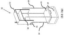
도 7a 및 7b는 아이템을 파지하고 미리 결정된 기동을 수행하는 로봇 시스템을 보여주는 개략도이다.
도 8은 손상된 아이템을 파지하는 로봇 시스템을 보여주는 개략도이다.
도 9는 본 발명의 제 1 실시예에 따른 제어 유닛에 의해 수행되는 프로세스의 흐름도이다.
도 10은 공지된 시스템에 따른 프레임워크 구조의 개략도이다.
도 11은 도 10의 프레임워크 구조체 내에 배치되는 빈들의 스택을 보여주는 상면도의 개략도이다.
도 12a 및 도 12b는 빈을 쌓는 부하 처리 디바이스의 개략적인 사시도이고, 도 12c는 빈을 인양하는 부하 처리 디바이스의 개략적인 전면 사시도이다.
도 13은 프레임워크 구조체에서 동작하는 부하 처리 디바이스를 보여주는 시스템의 개략도이다.Embodiments of the present invention will now be described, by way of example only, with reference to the accompanying drawings in which like reference numerals indicate identical or corresponding parts.
1 is a schematic diagram of a pick-up system according to known systems.
2 is a schematic diagram of a control device according to an embodiment of the present invention.
FIG. 3 is a graph showing a force that varies with time, detected by a sensor unit when the robot system picks up a first item and a second item, and the first item and the second item are not similar.
FIG. 4 is a graph showing a torque that varies with time and is detected by a sensor unit when the robot system picks up a first item and a second item, and the first item and the second item are not similar.
FIG. 5 is a graph showing forces that vary with time, detected by the sensor unit when the robot system picks up the first item and the second item, and the first item and the second item are similar.
6 is a graph showing a torque that varies with time and is detected by a sensor unit when the robot system picks up a first item and a second item, and the first item and the second item are similar.
7A and 7B are schematic diagrams showing a robotic system that grips an item and performs a predetermined maneuver.
8 is a schematic diagram showing a robotic system for gripping damaged items.
9 is a flowchart of a process performed by the control unit according to the first embodiment of the present invention.
10 is a schematic diagram of a framework structure according to a known system.
Fig. 11 is a schematic diagram of a top view showing a stack of beans disposed within the framework structure of Fig. 10;
12A and 12B are schematic perspective views of a load handling device for stacking bins, and FIG. 12C is a schematic front perspective view of a load handling device for lifting bins.
13 is a schematic diagram of a system showing a load handling device operating on a framework structure.
제 1 실시형태1st embodiment
도 2는 컨테이너(300)로부터 아이템을 파지하기 위한 시스템을 본 발명의 제 1 실시예에 따른 제어 유닛(100)과 함께 도시한다. 이러한 시스템에서, 상단 계층으로부터, 적어도 하나의 아이템을 보관하도록 배치되는 컨테이너(300)가 제공된다. 아이템을 컨테이너(300)로부터 파지하도록 구성되고 로봇 시스템(200)에 의해 파지된 아이템에 대한 정보를 기록하도록 구성되는 로봇 시스템(200)이 제공된다. 본 발명의 제 1 실시형태에 따른 제어 유닛(100)은, 로봇 시스템(200)에 의해 기록된 정보를 수신하도록 구성되고 로봇 시스템(200)에 의해 픽업된 아이템이 컨테이너(300) 내에 있을 것으로 기대되는 아이템으로부터 기대된 것과 매칭되는 동적 속성을 가진다는 것을 검증하도록 구성된다.2 shows a system for gripping items from a
더 자세히 말하면, 도시된 컨테이너(300)는 그들 중 적어도 하나가 로봇 시스템(200)에 의해서 컨테이너(300)로부터 이동하려고 하는 세 개의 아이템을 포함한다. 일 예에서, 컨테이너(300)는 오직 하나의 타입의 아이템만을 포함하는 것으로 기대될 수 있고, 여기에서 하나의 타입의 아이템 중 적어도 하나가 로봇 시스템(200)에 의해 컨테이너(300)으로부터 이동될 것이다. 이러한 방식으로, 픽업 시스템은 컨테이너(300) 내에 있을 것이 기대되는 아이템의 타입을 알고 있다. 그러나, 컨테이너(300)는 컨테이너(300) 내의 다른 아이템과 동일한 타입이 아닌 다른 아이템을 포함할 수도 있다. 예를 들어, 다른 타입의 아이템이 컨테이너(300) 내에 잘못 배치될 수 있고, 또는 컨테이너(300)는 두 개 이상의 타입의 아이템을 포함하도록 구성될 수도 있다. 이해될 수 있는 것처럼, 컨테이너(300)는 임의의 개수의 아이템을 포함하거나 아이템을 포함하지 않을 수 있다. 통상적으로, 컨테이너 아이템 및 아이템이 떨어지지 않게 하기 위한 벽, 예를 들어 4 개의 벽을 지지하는 하면, 즉 바닥을 포함한다. 그러나, 이해될 수 있는 것처럼, 컨테이너는 아이템을 홀딩하기 위한 임의의 크기 또는 구성, 예를 들어 세 개의 벽, 다섯 개의 벽 등을 포함하는 크기 또는 구성일 수 있다. 또는, 컨테이너(300)는 벽을 가지지 않아서, 이러한 구성에서는 팔레트라고 불릴 수 있는 바닥만을 포함할 수도 있다.More specifically, the illustrated
이상적으로는, 컨테이너(300) 내에 보유된 아이템은 벽의 상단 밑에 위치되지만, 제 1 실시예는, 예를 들어 컨테이너(300) 내에 있는 큰 아이템 때문에 또는 컨테이너(300) 내에 많은 수의 아이템이 쌓여 있기 때문에 아이템들이 벽의 상단을 넘어가는 컨테이너에도 동일하게 적용가능하다. 도 2에 도시된 컨테이너(300)는 세 개의 아이템인 장방형 아이템(301), 제 1 원통형 아이템(302) 및 제 2 원통형 아이템(303)을 포함한다. 이해될 수 있는 바와 같이, 아이템은 임의의 형상을 가질 수 있고, 반드시 장방형 또는 원통형이어야 할 필요가 없다.Ideally, the items held in the
더 나아가, 컨테이너(300)는 다른 컨테이너들 중에서 컨테이너(300)를 고유하게 식별하기 위한, 바코드와 같은 식별 수단을 포함할 수 있다. 이러한 방식으로, 픽업 시스템은 다른 컨테이너들 중에서 컨테이너(300)를 식별할 수 있다. 예를 들어, 복수 개의 컨테이너를 가지는 창고에서, 픽업 시스템은 식별 수단에 기반하여 각각의 컨테이너를 식별할 수 있다. 이러한 방식으로, 아이템이 각각의 컨테이너 내에 배치되면, 픽업 시스템은 각각의 컨테이너 내에 배치된 아이템을 기록할 수 있다. 로봇 시스템(200)이 컨테이너(300)에 픽업 동작을 수행하도록 허용되기 전에, 픽업 시스템은 컨테이너(300)를 식별하고, 이를 통하여 컨테이너(300)가 포함하는 것이 의도되는 아이템을 리콜하도록 구성될 수 있다. 제어 유닛(100)은 아이템(300-302)이 컨테이너(300)에 속하는지/컨테이너(300)로 이동되어야 하는지 여부를, 적어도 각각의 아이템의 동적 속성에 기반하여 검증하도록 구현된다.Furthermore, the
로봇 시스템(200)은 아이템을 컨테이너(300)로부터 파지하도록 제공된다. 특히, 로봇 시스템(200)은 아이템을 파지하도록 구성되는 엔드 이펙터(201)를 포함한다. 도 2에서 엔드 이펙터는 아이템을 파지하기 위하여 진공에 의존하는 석션 컵 엔드 이펙터(201)인 것으로 도시된다. 그러나, 석션 컵 엔드 이펙터 대신에 다른 엔드 이펙터가 사용될 수도 있다. 예를 들어, 평행 조(parallel jaw) 엔드 이펙터가 아이템을 컨테이너(300)로부터 파지하기 위하여 사용될 수 있다. 이를 통하여 로봇 시스템은 아이템(301-303)을 컨테이너(300)로부터 파지할 수 있다. 로봇 시스템(200)은 아이템(301-303)의 동적 속성을 측정하도록 구성되는 센서 유닛(202)을 더 포함한다. 이러한 관점에서, 센서 유닛(202)은 센서 유닛(202)에 상대적인 아이템의 모션으로부터 결과적으로 얻어지는 임의의 속성을 측정하도록 구성되는 것이 예상되는데, 이러한 속성은 비한정적으로, 아이템이 센서 유닛(202)에 작용시키는 압력, 토크 및/또는 힘, 아이템이 센서 유닛(202)에 작용시키는 가속도, 아이템의 내용물 천이의 소리, 및/또는 대상물이 아이템이 미끄러질 때 센서 유닛(202)에 작용시키는 전단력을 포함한다.A
로봇 시스템(200)은 파지된 아이템(301-303)을 제 1 컨테이너(300)로부터 제 2 컨테이너(미도시)로 이동시키도록 더 구성될 수 있다. 이를 통하여, 제 1 컨테이너(300)는 아이템을 창고 인벤토리 시스템 내에 보관할 수 있고, 제 2 컨테이너는 창고 인벤토리 시스템으로부터 고객이 주문한 아이템을 포함하도록 구성될 수 있다. 그러므로, 로봇 시스템(200)은 고객이 주문한 아이템을 제 1 컨테이너(300)로부터 선택적으로 파지한 후, 그러한 아이템을 고객에게 수송되도록 제 2 컨테이너 내에 배치하도록 구성될 수 있다. 그러므로, 로봇 시스템은 아이템을 제 1 컨테이너(300)로부터 제 2 컨테이너로 전달한다. 이에 상응하여, 고객에 대한 주문이 정확하다는 것을 보장하기 위하여, 파지된 아이템이 정확한 아이템인 것이 중요하다.The
본 발명의 제 1 실시형태에 따른 제어 유닛(100)은 아이템(301-303)의 동적 속성을 나타내는 측정된 정보를 센서 유닛(202)으로부터 수신한다. 제어 유닛(100)은 또한, 컨테이너(300) 내에 있을 것으로 기대되는 아이템을 식별하는 정보를 수신하도록 배치된다. 수신된 정보에 기반하여, 제어 유닛(100)은 로봇 시스템(200)에 의해 픽업된 아이템(301-303)이 컨테이너 내에 있을 것으로 기대되는 아이템에게 기대된 동적 속성을 가지는 것을 검증하도록 구성된다. 동적 속성은 아이템의 관성(inertial) 속성, 아이템의 댐핑 속성 및/또는 아이템 및 그 내용물의 소리 중 적어도 하나인 것으로 기대된다. 이와 유사하게, 동적 속성은 모션에 의해 유도되는 속성을 포함하는 것으로 기대된다. 예를 들어, 동적 속성은, 예를 들어 아이템이 엔드 이펙터에서 미끄러지는 방식으로 아이템을 이동시키고 이러한 슬립을 엔드 이펙터 및 아이템 사이의 마찰의 척도로서 사용하는 로봇 시스템(200)에 의해 유도되는 전단력 속성을 포함하는 것이 기대된다. 예를 들어, 엔드 이펙터는 능동적으로 그 핑거를 아이템의 표면에 걸쳐 문지르거나, 아이템이 엔드 이펙터가 아이템을 파지하는 동안에 미끄러지게 할 수 있다. 동적 속성이 언급되었지만, 하나 이상의 동적 속성은 임의의 하나의 시점에 측정됨으로써 그 검증에 적합한 아이템에 대한 정보를 제공할 수 있다는 것이 이해될 것이다. 예를 들어, 관성 속성 및 댐핑 속성 양자 모두가 동시에 측정되어 아이템 검증을 위해 필요한 정보를 제공할 수도 있다.The
예를 들어, 픽업 시스템은 컨테이너(300)가 제 1 원통형 아이템(302)만을 포함하며, 제 1 원통형 아이템들(302)은 토마토 소스 제품의 병과 같은 고형 아이템을 각각 포함한다고 기록했을 수 있다. 그러나, 컨테이너(300)를 패킹할 때의 오류(예컨대 사람이 컨테이너(300) 내에 잘못된 아이템을 배치하는 것) 때문에, 제 1 원통형 아이템(302) 중에는 제 2 원통형 아이템(303)이 있을 수도 있고, 제 2 원통형 아이템(303)은 피클 제품의 병을 포함한다. 이에 상응하여, 아이템의 형상에만 기반할 경우, 이러한 아이템들을 구별하는 것이 불가능할 것이다. 통상적인 기법은 느리고, 흔히 아이템들이 바코드 스캐너 앞에 일시 정지하도록 요구한다.For example, the pickup system may have written that the
그 대신에, 본 발명의 제 1 실시형태는 아이템의 동적 속성에 의존함으로써 파지된 아이템이 기대된 아이템이라는 것을 검증한다. 특히, 아이템의 검증은 아이템 이동되는 동안에 아이템이 어떻게 반응하는지를 측정함으로써 수행된다. 예를 들어, 로봇 시스템(200)이 제 1 컨테이너(300)로부터 제 2 컨테이너(미도시)로 아이템을 전달하는 경우, 아이템의 검증은 로봇 시스템(200)이 아이템을 전달하는 동안에 수행될 수 있다. 그러므로, 로봇 시스템(200)이 바코드 스캐너 앞에서 멈출 필요가 없기 때문에 속도 증가가 실현된다. 그 대신에, 제 1 컨테이너(300)로부터 제 2 컨테이너로의 아이템의 필요한 이동이 아이템의 아이덴티티를 검증하기 위해서도 사용된다. 본 발명의 제 1 실시형태는 로봇 시스템(200)이 이미징 유닛에 의한 아이템 검증을 위해서 멈출 필요성을 없앰으로써, 아이템 전달의 효율을 증가시키는 장점을 제공한다.Instead, the first embodiment of the present invention verifies that the held item is the expected item by relying on the dynamic properties of the item. In particular, validation of an item is performed by measuring how the item reacts while being moved. For example, when the
일 예에서, 아이템(301-303)을 이동시킴으로써 아이템이 점점 빨라지게 하는 힘/토크가 아이템(301-303)에 작용된다. 아이템의 가속도는 아이템(301-303)의 동적 속성에 대응한다. 이러한 예에서, 토마토 소스 제품의 병은 피클 제품의 병과 다른 방식으로 이동할 것이고, 예를 들어 토마토 소스 제품의 (균질한) 병은 피클의 형태인 커다란 고형물을 포함하는 피클 제품의 병과 다른 동적 속성(예컨대, 상이한 출렁거림 특성)을 보여줄 것이다. 이를 통하여, 출렁거림이 이러한 힘/토크를 측정하도록 구성되는 }센서 유닛(202)에 힘/토크를 인가할 것이다. 측정된 힘/토크에 기반하여 제어 유닛(100)은 아이템의 동적 속성을 컨테이너 내에 있을 것으로 기대되는 아이템의 동적 속성과 비교함으로써 아이템을 검증하도록 구성된다. 예를 들어, 비교는 머신 러닝을 사용하는 통계적 모델을 사용하여 수행되어, 센서 유닛(202)에 의해 측정된 동적 속성과 컨테이너 내에 있을 것으로 기대되는 아이템의 기대된 동적 속성 사이의 유사도의 양을 결정할 수 있다. 바람직하게는, 통계적 모델은 센서 유닛(202)으로부터 얻어진 측정치에 있는 잡음 및 드리프트(예컨대, 온도 드리프트)를 처리하도록 구성된다. 예를 들어, 센서 유닛(202) 출력은 엔드 이펙터에 상대적인 아이템의 자세의 변동으로부터 얻어질 수 있다. 더 나아가, 상이한 센서 유닛들(202)이 사용되는 경우, 통계적 모델은 여러 센서 유닛(202)에 걸쳐서 일반화하도록 구성될 수 있다. 또는, 통계적 모델은 특정한 센서 유닛(202)에 대해서 훈련될 수 있다.In one example, by moving items 301-303, a force/torque is applied to items 301-303 that cause them to accelerate. The acceleration of an item corresponds to the dynamic properties of items 301-303. In this example, a bottle of tomato sauce product will move in a different way than a bottle of pickle product, for example a (homogeneous) bottle of tomato sauce product has a different dynamic property than a bottle of pickle product containing large solids in the form of a pickle ( eg different sloshing characteristics). Through this, the sloshing will apply a force/torque to the
상기 예에서, 개시된 센서 유닛(202)은 힘 및/또는 토크를 측정하도록 구현된다. 그러나, 측정의 다른 속성, 즉 센서 유닛(202)에 상대적인 아이템의 모션으로부터 얻어지는 속성이 기대되는데, 이러한 속성은 비한정적으로, 아이템이 센서 유닛(202)에 작용시키는 압력, 아이템이 센서 유닛(202)에 작용시키는 가속도, 아이템의 내용물 천이의 소리, 및/또는 대상물이 아이템이 미끄러질 때 센서 유닛(202)에 작용시키는 전단력을 포함한다.In this example, the disclosed
전술된 예들이 고형 아이템이 액상 아이템과 비교되는 것을 언급하지만, 임의의 타입의 아이템들이 비교될 수 있다는 것이 예상된다. 예를 들어, 장방형 아이템(301)이 상이한 고형 아이템, 예컨대 빵을 포함한다면, 제 1 원통형 아이템(302)의 빵 아이템 및 케이크 아이템의 동적 속성은 제 2 원통형 아이템(303)의 액상 아이템보다 더 유사할 것이다. 그러나, 적절하게 훈련된 통계적 모델이 있으면, 아이템들 사이의 차이가 확인될 수 있고, 따라서 픽업된 아이템이 제어 유닛(100)에 의해 검증될 수 있다. 더 나아가, 하나의 컨테이너로부터 다른 컨테이너로 전달된 아이템의 개수의 카운팅이 특정 주문에 대한 정확한 개수의 아이템이 픽업되었다는 것을 결정하기 위하여 사용될 수 있다.Although the foregoing examples refer to a solid item being compared to a liquid item, it is contemplated that any type of item may be compared. For example, if the
도 2에 도시된 시스템은, 선택적으로, 이미징 유닛(500)을 더 포함한다. 이미징 유닛은 아이템을 표시하는 정보를 수신하도록 구현된다. 예를 들어, 이미징 유닛(500)은 바코드 스캐너 및/또는 컴퓨터 비전 이미저를 포함할 수 있다. 이러한 이미징 유닛(500)은 아이템(301-303)을 식별하기 위하여 제어 유닛(100)을 트레이닝하는 동안에 활용될 수 있다. 특히, 통상적인 시스템에서와 같이, 아이템이 제 1 컨테이너(300)로부터 제 2 컨테이너로 이동되는 동안에 아이템의 동적 속성이 센서 유닛(202)에 의해 기록되고 제어 유닛(100)으로 송신된다. 그러나, 최초에는, 제어 유닛(100)은 로봇 시스템(200)이 어떤 아이템을 파지했는지를 알지 못할 것이고, 따라서 픽업된 아이템이 컨테이너 내에 있을 것으로 기대되는 아이템이라는 것을 검증할 수 없을 것이다. 그러므로, 로봇 시스템(200)은 또한 아이템을 종래의 방식으로 바코드 스캐너 및/또는 컴퓨터 비전 이미저를 사용하여 이미징하도록 명령될 것이다. 이러한 방식으로, 제어 유닛(100)은 아이템의 아이덴티티에 대한 표시를 이미징 유닛(500)으로부터 수신할 수 있다. 그러므로, 충분한 트레이닝 정보가 수집되면, 제어 유닛(100)은 아이템이 로봇 시스템(200)에 의해 후속하여 파지될 때, 로봇 시스템(200)이 아이템을 이미징 유닛(500)을 거치도록 전달할 필요가 없이 성공적으로 검증할 수 있을 것이다.The system shown in FIG. 2 optionally further includes an
제 1 실시형태에 따른 제어 유닛(100)은 검증 유닛(101)을 포함한다. 선택적으로, 제어 유닛(100)은 트레이닝 유닛(102) 및/또는 명령 유닛(103)을 포함할 수 있다.The
검증 유닛(101)은 로봇 시스템(200)에 의해 픽업된 아이템의 동적 속성을 나타내는 정보를 센서 유닛(202)으로부터 수신하도록 구현된다. 더 나아가, 검증 유닛(101)은 컨테이너(300) 내에 있을 것으로 기대되는 아이템의 식별 정보를 수신하도록 구현된다. 검증 유닛(101)은 또한, 로봇 시스템(200)에 의해 픽업된 아이템이 컨테이너(300) 내에 있을 것으로 기대되는 아이템과 같은 것이라는 것을 검증하도록 구성된다. 이것은, 컨테이너 내에 있을 것으로 기대되는 아이템의 동적 속성 및 로봇 시스템(200)에 의해 현재 픽업된 아이템 사이의 유사도를 찾도록 구성되는 통계적 모델을 사용하여 수행될 수 있다.The
통계적 모델은 입력으로서, 기대된 아이템/아이템들의 클래스에 대한 식별자, 및 측정된 동적 속성을 받도록 구성될 수 있다. 이것은 측정치를 배치(batch)로서, 로봇 시스템(200)이 아이템을 특정 지점에 소송한 후에 수신할 수 있고, 또는 측정치를 스트림으로서 수신하여 각각의 측정치가 생성될 때 처리할 수도 있다. 전자의 경우에, 통계적 모델은 출력으로서 측정된 동적 속성이 로봇 시스템(200)이 기대된 아이템을 픽업했다는 것을 나타낼 확률을 생성하도록 구성될 수 있다. 후자의 경우에는, 통계적 모델은 출력으로서, 예를 들어 도달하는 측정치마다 하나씩의 이러한 확률의 스트림을 생성하도록 구성될 수도 있다. 전자의 경우에, 출력 확률은 미리 결정된 임계와 비교됨으로써 로봇 시스템(200)이 기대된 아이템을 픽업했는지 여부를 판정할 수 있다. 후자의 경우에, 확률의 스트림은 평가되어 로봇 시스템(200)이 기대된 아이템을 픽업했는지 여부를 결정할 수도 있다.The statistical model can be configured to receive as input an identifier for the expected item/class of items, and the measured dynamic property. This can be received as a batch of measurements, after the
임의의 기대된 아이템/클래스 식별이 주어지면, 통계적 모델은 표준 머신 러닝 모델, 예컨대 인공 신경망 또는 가우시안 프로세스 분류기의 형태를 취할 수 있다. 통계적 모델은 선택적으로, 가속하는 대상물의 동적 특성에 대한 사전 정보, 예컨대, 가속도-불변 동적 속성을 포함할 수도 있다.Given any expected item/class identification, the statistical model can take the form of a standard machine learning model, such as an artificial neural network or a Gaussian process classifier. The statistical model may optionally include prior information about the dynamic properties of an accelerating object, such as acceleration-invariant dynamic properties.
이러한 방식으로, 제어 유닛(100)은 로봇 시스템(200)으로부터 동적 속성 정보를 수신하고, 이를 통하여 로봇 시스템(200)에 의해 파지되고 있는 아이템 또는 아이템들의 클래스를 검증하도록 구성된다. 특히, 검증은 로봇 시스템(200)의 위치 및 제 1 컨테이너로부터 제 2 컨테이너까지 로봇 시스템(200)에 의해 취해지는 경로의 사소한 변동에 대해서 불변이다.In this way, the
선택적으로, 제어 유닛(100)은 트레이닝 유닛(102)을 더 포함할 수 있다. 트레이닝 유닛(102)은, 검증 유닛(101)이 파지되는 아이템을 검증할 수 없을 경우, 측정된 센서 정보 및 아이템 식별자에 기반하여 통계적 모델을 훈련시키도록 구성된다. 특히, 트레이닝 유닛(102)은 로봇 시스템(200)에 의해 파지되는 아이템의 동적 속성을 표시하는 정보를 수신하도록 구현된다. 더 나아가, 트레이닝 유닛(102)은 더 나아가 아이템 식별자를 수신하도록 구현된다. 예를 들어, 아이템 식별자는 바코드 또는 이미지-기반 대상물 분류의 형태로 이미징 유닛(500)으로부터 수신될 수 있다. 수신된 정보에 기반하여, 트레이닝 유닛(102)은 통계적 모델을 재훈련시키도록 구현된다. 이러한 방식으로, 동일한 아이템/아이템들의 클래스가 장래의 시간에 파지될 때, 검증 유닛(101)은 트레이닝 유닛(102)에 의해 훈련된 정보에 기반하여 아이템을 정확하게 검증할 수 있을 것이다. 예를 들어, 트레이닝 유닛(102)은 수신된 아이템 식별자 및 아이템의 동적 속성을 나타내는 정보를 사용하여 통계적 모델을 재훈련시킴으로써 통계적 모델을 업데이트하도록 구성될 수 있다. 이러한 방식으로, 로봇 시스템(200)에 의해 파지될 새로운 아이템이 통계적 모델에 추가됨으로써, 아이템이 로봇 시스템(200)에 의해 장래에 픽업될 경우 검증 유닛(102)에 의해 검증될 것이다.Optionally, the
다른 정보가 훈련된 통계적 모델에 추가되어 그 정확도를 높일 수 있다. 예를 들어, 아이템의 공칭 무게, 치수 등이다. 이러한 방식으로 통계적 모델의 클래스가 발견될 수 있는데, 여기에서 한 클래스 내의 각각의 통계적 모델은 공칭 파라미터에 의해 규정된다. 유리하게도, 그러면 필요한 저장 공간의 양이 줄어들고, 필요한 트레이닝 데이터의 양이 줄어든다.Other information can be added to the trained statistical model to increase its accuracy. For example, the item's nominal weight, dimensions, etc. In this way, classes of statistical models can be discovered, where each statistical model within a class is defined by a nominal parameter. Advantageously, this reduces the amount of storage space required and reduces the amount of training data required.
또는, 검증 유닛(101)은 아이템들의 클래스만을 검출하도록 구성될 수 있는데, 예컨대, 모든 차 상자는 하나의 클래스를 형성하고 병입된 음료들 모두는 다른 클래스를 형성한다. 그러므로, 통계적 모델을 특정 SKU(stock keeping unit), 예를 들어 특정 크기의 특정 크기의 차 상자에 대해 훈련시키는 대신에, 트레이닝 유닛(102)은 SKU들의 클래스에 대해서 훈련될 것이다. 이러한 방식으로, 각각의 SKU에 대한 트레이닝 정보를 캡쳐할 필요성이 없어진다. 그 대신에, 특정 SKU의 크기 및 표시 무게가, 동일한 클래스의 다른 SKU와 동일한 연관된 측정된 센서 정보가 적용될 SKU들의 특정 클래스의 SKU를 자동적으로 분류하기 위해서 사용될 수 있다. 이러한 관점에서, SKU의 공칭 무게/크기 및 연관된 동적 속성 사이의 관련성이 구축될 필요가 있을 것이라는 것이 예상된다. SKU는 수동으로 클래스 내에 클러스터링될 수 있는데, 이러한 경우에는 관련성의 속성을 결정하기 위하여 한 클래스 내의 SKU들 중 일부를 검사하면 충분할 수 있다. 또는, SKU는 자동적으로 클러스터링될 수 있는데, 그러면 각각의 SKU에 대한 트레이닝 정보의 캡쳐링이나 더 적은 트레이닝 정보를 요구하는 각각의 클래스 내의 더 간단한 통계적 모델을 사용하는 것이 필요할 수 있다. 힘 감지 수단/토크 감지 수단(예컨대, 힘 및/또는 토크를 측정하도록 구성되는 센서 유닛(202))을 포함하는 로봇 시스템(200)이 SKU의 공칭 무게를 자동적으로 결정하기 위하여 사용될 수 있다. 특히, 로봇 시스템(200)은, 로봇 시스템(200)이 아이템을 파지하고 들어올렸지만 이동하지 않을 때에, 중력장 때문에 엔드 이펙터에 인가된 힘을 측정함으로써 SKU의 무게를 통계적으로 결정할 수 있다. 그러므로, 로봇 시스템(200)의 위치에서 알려져 있는 중력장 세기에 의해서 아이템의 무게가 계산될 수 있다.Alternatively, the
비록, 양자 모두의 타입의 아이템(예를 들어 특정 브랜드의 특정 크기의 차 상자 - 고유한 SKU(stock keeping unit) 코드를 가질 것임) 및 특정한 아이템(예를 들어 픽업된 특정한 차 상자)을 가리키기 위해서 "아이템" 이라는 용어가 사용되었지만. '아이템'은 더 광범위하게 사용될 수 있다는 것이 예상된다. 예를 들어, 비록 두 아이템들이 동일한 SKU 코드를 가지고, 즉 동일한 브랜드 및 크기의 차 상자에 관련될 수 있지만, 제조 차이 및/또는 상자의 내용물의 분포 때문에 작은 무게 및/또는 동적 속성의 차이가 존재할 수 있다. 이를 위하여, 전술된 검증 방법은 검증을 결정할 때에 이러한 인자들을 고려할 수 있다. 예를 들어, 평균 무게 또는 무게의 하한이 사용될 수 있다.Although, pointing to both types of items (e.g. a certain size tea box of a certain brand - will have a unique stock keeping unit (SKU) code) and a specific item (e.g. a specific tea box picked up) Although the term "item" was used for It is expected that 'items' can be used more broadly. For example, although two items may have the same SKU code, i.e. relate to tea boxes of the same brand and size, there may be minor differences in weight and/or dynamic properties due to manufacturing differences and/or the distribution of the contents of the boxes. can To this end, the verification method described above may take these factors into account when determining verification. For example, an average weight or a lower bound on weight may be used.
또한, 제어 유닛(100)은 명령 유닛(103)을 선택적으로 포함할 수 있다. 명령 유닛(103)은 로봇 시스템(200)에게 미리 결정된 방식으로 이동하도록 명령하게끔 구현된다. 예를 들어, 명령 유닛(103)은 로봇 시스템(200)이 검증 유닛(101)에 의한 아이템의 검증 이전에 특정 방식으로 이동하도록 명령하게끔 구성될 수 있다. 이러한 방식으로, 주어진 아이템의 측정된 동적 속성의 특징들을 구별하는 것을 강조하기 위해서 로봇 시스템(200)이 사용될 수 있다. 추가적으로 또는 적으로, 명령 유닛(103)은 로봇 시스템(200)이 검증 유닛(101)이 아이템을 검증하지 못한 후에 미리 결정된 방식으로 이동하도록 명령하게끔 구성될 수 있다. 예를 들어, 제 1 미리 결정된 이동 방식이 아이템을 식별하는 것을 실패하면, 대응하는 동적 속성 정보가 통계적 모델에서 훈련되는 이와 다른 제 2의 미리 결정된 이동 방식이 검증 유닛(101)이 아이템을 검증하게 할 수 있다. 그러므로, 이미징 유닛(500)을 사용하지 않고서 아이템을 더 정확하게 검증할 수 있다.Also, the
도 3은 센서 유닛(202)에 의해 측정된 시간 대 힘을 도시하는 그래프이다. 이러한 그래프는 제 1 아이템 및 제 2 아이템 양자 모두에 대한 측정된 힘을 보여주는데, 여기에서 제 1 아이템 및 제 2 아이템은 유사하지 않다. 예를 들어, 제 1 아이템은 빵 아이템일 수 있고 제 2 아이템은 음료 아이템이다. 로봇 시스템(200)이 미리 결정된 이동을 수행하는 동안에 힘 측정이 이루어졌다. 각각의 아이템에 대해 도시된 선은 실질적으로 다르다. 그러므로 각각의 아이템/아이템들의 클래스에 대해서 상대적으로 개별적인 힘 대 시간 시그니쳐(signature)가 표시된다.3 is a graph showing force versus time measured by
이와 유사하게, 도 4는 센서 유닛(202)에 의해 측정된 시간 대 토크를 도시하는 그래프이다. 도 4에서 토크 측정은 두 개의 비유사 아이템에 대해서 이루어졌다. 도 3의 경우에서와 같이, 도시된 선들은 각각의 아이템에 대한 상이한 토크 시그니쳐들이다. 도 3 및 4 모두에서 힘 및 토크는 한 축 중심으로 측정된다. 그러나, 힘 및/또는 토크는 추가적인 축 중심으로 측정되어 적어도 하나의 축 중심의 힘 및/또는 토크 측정치에 기반하여 각각의 아이템/아이템들의 클래스에 대한 더 개별적인 시그니쳐를 생성할 수 있다.Similarly, FIG. 4 is a graph showing torque versus time measured by
도 5는 유사한 두 개의 아이템에 대한 시간 대 힘을 도시하는 그래프를 보여준다. 도 5에서 도시된 바와 같이, 측정된 힘에 의해 도시되는 선들은 제 1 및 제 2 아이템에 대해서 실질적으로 유사하다. 그러므로, 제 1 아이템에 대한 힘 대 시간 그래프에 대한 정보를 포함하는 제어 유닛(100)은 제 2 아이템에 대한 힘 대 시간 그래프로부터 제 1 및 제 2 아이템이 동일한 타입의 아이템/동일한 아이템들의 클래스라는 것을 결정할 수 있을 것이다.5 shows a graph depicting force versus time for two similar items. As shown in Figure 5, the lines drawn by the measured forces are substantially similar for the first and second items. Therefore, the
이와 유사하게, 도 6은 두 개의 유사한 아이템에 대한 시간 대 토크를 도시하는 그래프이다. 도 5에서와 같이, 토크 측정에 의해 도시되는 두 선들은 실질적으로 유사하고, 이를 통하여 각각의 아이템/아이템들의 클래스가 그들과 연관될 수 있는 시그니쳐를 가진다는 것을 표시한다.Similarly, Figure 6 is a graph depicting torque versus time for two similar items. As in Fig. 5, the two lines drawn by the torque measurement are substantially similar, indicating that each item/class of items has a signature that can be associated with them.
전술된 바와 같이, 선택적인 명령 유닛(103)이 로봇 시스템(200)이 미리 결정된 기동을 수행하도록 명령하게끔 구성될 수 있다. 일 예에서, 아이템의 동적 속성에 대한 정보를 수집하기 위하여, 로봇 시스템(200)은 엔드 이펙터(201)가 제 1 컨테이너로부터 제 2 컨테이너로 이동하는 동안 엔드 이펙터(201)를 회전시키도록 명령될 수 있다. 이러한 방식으로, 더 간단한 궤적의 정보와 비교되는 추가적인 동적 정보는 제 2 컨테이너에 도달하는 데에 걸리는 시간을 놀리지 않고서 수집될 수 있다.As discussed above, an
도 7a는 엔드 이펙터(201)에 의해 파지된 아이템(301)을 제 2 컨테이너(400)(이것이 목적지 컨테이너임)로 이동시키기 위해서 로봇 시스템(200)이 취하는 미리 결정된 기동의 일 예를 도시한다. 이러한 예에서, 로봇 시스템(200)은 제 2 컨테이너(400)로 전달하기 위해서, 제 1 컨테이너(미도시)로부터 아이템(301)을 파지했을 수 있다. 제 1 실시형태에 따른 제어 유닛(100)이 있으면, 유리하게는, 로봇 시스템(200)이 바코드 스캐닝 공정을 수행하기 위해서 한 위치에서 정지할 필요가 없다. 그 대신에, 로봇 시스템(200)은 중단하지 않고 아이템(301)을 제 2 컨테이너(400)에 수송할 수 있다. 제 1 컨테이너로부터 제 2 컨테이너(400)로 가는 간단한 아크형(arcing) 모션이 구성되지만(엔드 이펙터의 상향 이동, 측방향 병진 및 엔드 이펙터의 하향 이동을 포함함), 다른 대안들도 사용될 수 있다. 예를 들어, 아크형 모션은 검증 유닛(101)이 아이템/아이템들의 클래스를 정확하게 검증하기 위한 충분한 측정된 센서 정보를 제공하지 않을 수도 있다. 이에 상응하여, 다른 미리 결정된 이동이 예상된다. 도 7a는 검증 유닛(101)에 의한 아이템/아이템들의 클래스의 검증 이전에 수행될 수 있는 이동을 보여준다. 이러한 예에서, 아이템 식별을 돕기 위한 더 많은 센서 정보를 측정하기 위한 가능성을 제공하기 위하여, 여러 번의 가속 및 감속이 상이한 축들을 따라서 수행된다. 그러나, 도 7a에 도시된 미리 결정된 기동에서는, 제 2 컨테이너(400)로의 약간 더 긴 경로가 선택된다.7A shows an example of a predetermined maneuver taken by the
도 7b는 명령 유닛(103)에 의해 명령될 수 있는 다른 미리 결정된 기동을 보여준다. 예를 들어, 도 7b의 기동은, 도 7a의 기동이 수행되었지만(그리고 따라서 아이템(301)이 제 2 컨테이너(400) 위에 있지만) 검증 유닛(101)이 아이템/아이템들의 클래스를 식별할 수 없었던 경우에 명령될 수 있다. 이미징 유닛(500)에 의존하는 대신에, 더 많은 가속/감속이 있는 추가적인 센서 정보를 수집하기 위해서 다른 기동을 수행하는 것이 예상된다. 그러므로, 도 7b의 기동은 도 7a 에서보다 많은 이동을 포함하지만, 아이템(301)의 시작 위치와 끝 위치는 같다. 이러한 방식으로, 도 7b의 기동을 수행한 후에 그리고 검증 유닛(101)이 아이템/아이템들의 클래스를 성공적으로 검증한 후에, 로봇 시스템(200)은 아이템(301)을 제 2 컨테이너(400) 내에 배치할 수 있다. 그러나, 이러한 기동은 너무 많은 시간이 걸릴 수 있고, 따라서, 일부 경우에서는 아이템의 아이덴티티를 검출하기 위해서 이미징 유닛(500)을 활용하는 것이 더 빠를 수도 있다.7b shows another predetermined maneuver that can be commanded by
도 8은 본 발명의 제 1 실시형태에 따른 제어 유닛(100)의 다른 애플리케이션을 보여준다. 특히, 검증 유닛(101)은 손상된/불완전한 아이템을 검출하도록 구성될 수 있다. 예를 들어, 로봇 시스템(200)은 아이템(303)을 파지할 수 있다. 그러나, 도 8에 도시된 바와 같이 아이템(303)은 손상되어서 제 1 부분(303a) 및 제 2 부분(303b)으로 나뉠 수도 있다. 따라서 이러한 손상이 제어 유닛(100)에 의해 검출될 수 있는데, 그 이유는 센서 유닛(202)에 의해 측정된 동적 속성이 컨테이너(300) 내에 있을 것으로 기대되는 아이템의 동적 속성과 다르기 때문이다. 그러므로, 로봇 시스템(200)은 아이템(303)을 아이템(303)을 처분하거나 그렇지 않으면 아이템(303)을 보수하기 위한 위치에 배치하도록 더 구성될 수도 있다. 이와 유사하게, 아이템이 불완전하고, 예를 들어 제 2 부분(303b)이 제 1 부분(303a)으로부터 완전히 분리되면, 제어 유닛(100)은 또한 해당 아이템이 불완전하다고 검출할 수 있을 수도 있다. 손상된 아이템과 유사하게, 검증 유닛(101)은 센서 유닛(202)으로부터의 정보에 기반하여, 아이템의 동적 속성이 아이템이 불완전하다는 것을 나타내는 방식으로 변했다는 것을 검출하도록 구성될 수 있다.8 shows another application of the
더 나아가, 제어 유닛(100)은 엔드 이펙터(200)에 의해 파지된 아이템이 복수 개의 아이템을 포함하는지 여부를 식별하도록 구성될 수 있다. 예를 들어, 추가적인 아이템이 픽업된 아이템에 부착되었을 수 있다. 이에 상응하여, 로봇 시스템(200)이 제 1 아이템을 픽업하면, 거기에 부착된 제 2 아이템은 로봇 시스템(200)이 제 1 아이템을 제 1 컨테이너로부터 제 2 컨테이너로 이동시킬 때에 제 1 아이템과 함께 이동할 것이다. 제 2 아이템이 추가되면 제 1 아이템의 동적 속성이 제어 유닛(100)에 의해 검출될 수 있는 방식으로 변한다.Furthermore, the
추가적으로, 제어 유닛(100)은 하나의 컨테이너로부터 다른 컨테이너로 전달된 아이템의 개수를 카운팅하도록 구성될 수 있다. 이러한 방식으로, 전달된 아이템의 개수가 특정 고객의 주문에 있을 것으로 기대되는 아이템의 개수와 비교될 수 있다. 그러므로, 제어 유닛(100)은, 고객의 주문에 포함되는 기대된 개수가 될 때까지 로봇 시스템이 아이템을 계속 픽업하게 하도록 구성될 수 있는데, 이러한 시점에서 제어 유닛(100)은 로봇 시스템이 임의의 추가적인 아이템을 픽업하는 것을 중지시키도록 구성될 수 있다.Additionally, the
도 9는 제 1 실시형태에 따르는, 로봇 시스템(200)의 센서 유닛(202)으로부터 수신된 동적 속성을 사용하여 아이템을 식별하기 위해서 수행되는 프로세스를 도시한다.FIG. 9 shows the process performed to identify an item using dynamic attributes received from the
도 9를 참조하면, 단계 S901에서 아이템 식별자에 대한 정보(예컨대, 바코드, 제품명 등)가 수신된다. 예를 들어, 아이템 식별자는 창고 내의 컨테이너 및 그들의 내용물을 관리하도록 구성되는 픽업 시스템으로부터 수신될 수 있다. 픽업 시스템은 컨테이너 및 그것의 기대된 내용물의 정보를 가질 수 있다. 따라서, 컨테이너 내의 아이템의 식별이 단계 S901로 송신될 수 있다.Referring to FIG. 9 , in step S901, information on item identifiers (eg, barcodes, product names, etc.) is received. For example, item identifiers may be received from a pickup system configured to manage containers and their contents within a warehouse. The pickup system may have information of the container and its expected contents. Accordingly, the identification of the item in the container may be transmitted to step S901.
단계 S902에서, 이러한 방법은 아이템의 동적 속성을 나타내는 정보를 센서 유닛(202)으로부터 수신한다. 이러한 관점에서, 센서 유닛(202)은 센서 유닛(202)에 상대적인 아이템의 모션으로부터 결과적으로 얻어지는 임의의 속성을 측정하도록 구성되는 것이 예상되는데, 이러한 속성은 비한정적으로, 아이템이 센서 유닛(202)에 작용시키는 압력, 토크 및/또는 힘, 아이템이 센서 유닛(202)에 작용시키는 가속도, 아이템의 내용물 천이의 소리, 및/또는 대상물이 아이템이 미끄러질 때 센서 유닛(202)에 작용시키는 전단력을 포함한다.In step S902, the method receives information representing the dynamic attribute of the item from the
단계 S903에서, 픽업된 아이템/아이템들의 클래스는 단계 S901 및 S902에서 수신된 동적 속성 및 수신된 정보에 기반하여 검증된다. 다르게 말하면, 단계 S902에서 수신된 정보가 컨테이너 내에 있을 것으로 기대되는 아이템/아이템들의 클래스의 동적 속성의 통계적 모델과 비교된다. 수신된 정보가 통계적 모델 기대치와 매칭되면, 단계 S903은 픽업된 아이템이 컨테이너 내에 있을 것으로 기대되는 것이라고 검증한다. 이것이 개별적인 아이템에 적용될 수 있지만, 이것은 아이템들의 클래스에도 동일하게 적용될 수 있고, 예컨대 차 상자가 하나의 클래스를 형성하고 음료의 병이 다른 클래스를 형성한다.In step S903, the picked up item/class of items is verified based on the received information and dynamic attributes received in steps S901 and S902. In other words, the information received in step S902 is compared with a statistical model of the dynamic properties of the item/class of items expected to be in the container. If the received information matches the statistical model expectations, step S903 verifies that the picked-up item is what is expected to be in the container. While this can be applied to individual items, it can equally be applied to classes of items, e.g. a tea box forms one class and a bottle of beverage forms another.
이러한 방식으로, 아이템 검증이 종래의 기법에 의해 요구되는 시간을 줄이는 방식으로 수행된다.In this way, item verification is performed in a manner that reduces the time required by conventional techniques.
수정예 및 변형예Modifications and Variations
많은 수정과 변형이 본 발명의 범위에서 벗어나지 않으면서 전술된 실시예에 이루어질 수 있다.Many modifications and variations can be made to the above described embodiments without departing from the scope of the present invention.
온라인 식료품 및 수퍼마켓과 같이 여러 제품 라인을 판매하는 온라인 소매 비즈니스에는, 수 십 개 또는 심지어 수 백 수 천 개의 상이한 제품 라인을 보관할 수 있는 시스템이 요구된다. 이러한 경우에 단일-제품 스택을 사용하는 것은 실용적이지 않을 수 있는데, 그 이유는 요구되는 스택 모두를 수용하려면 매우 넓은 바닥면적이 요구될 것이기 때문이다. 더욱이, 상하거나 가끔 주문되는 제품과 같은 일부 아이템은 적은 양만 보관하는 것이 바람직할 수 있어서, 단일-제품 스택이 비효율적인 솔루션이 된다.Online retail businesses that sell multiple product lines, such as online groceries and supermarkets, require systems that can stock dozens or even hundreds of thousands of different product lines. In this case, using a single-product stack may not be practical, since a very large floor area would be required to accommodate all of the required stacks. Moreover, some items, such as perishable or infrequently ordered products, may be desirable to store in small quantities, making single-product stacks an inefficient solution.
그 내용이 본 명세서에서 원용에 의해 통합되는 국제 특허 출원 WO 98/049075A(Autostore)는 컨테이너의 다중 제품 스택이 프레임 구조체 내에 배치되는 시스템을 기술한다.International patent application WO 98/049075A (Autostore), the content of which is incorporated herein by reference, describes a system in which a multi-product stack of containers is placed within a frame structure.
PCT 공개 번호 제 WO2015/185628A(Ocado)는 빈 또는 컨테이너의 스택이 프레임워크 구조체 내에 배치되는, 추가적인 공지된 보관 및 실현 시스템을 기술한다. 빈(bin) 또는 컨테이너는 프레임 구조체의 상단에 위치된 트랙에서 동작하는 화물 처리 디바이스에 의해 액세스된다. 화물 처리 디바이스는 빈 또는 컨테이너를 스택으로부터 들어올리고, 스택의 최저 위치에 위치된 빈 또는 컨테이너에 액세스하기 위해서 여러 수화물 처리 디바이스가 협동한다. 이러한 타입의 시스템은 개략적으로 첨부 도면 중 도 10 내지 도 13에 예시된다.PCT Publication No. WO2015/185628A (Ocado) describes a further known storage and realization system in which a stack of bins or containers is placed within a framework structure. Bins or containers are accessed by cargo handling devices operating on tracks located on top of the frame structure. A baggage handling device lifts a bin or container from the stack, and several baggage handling devices cooperate to access the bin or container located at the bottom of the stack. A system of this type is schematically illustrated in FIGS. 10-13 of the accompanying drawings.
도 10 및 도 11에 도시된 바와 같이, 빈(10)이라고 알려지는 바와 같은 적층가능 컨테이너가 서로의 위에 적층되어 스택(12)을 형성한다. 스택(12)은 창고 또는 제조 환경에 있는 격자 프레임워크 구조체(14) 내에 배치된다. 도 10은 프레임워크 구조체(14)의 개략적인 사시도이고, 도 11은 프레임워크 구조체(14) 내에 배치된 빈(10)의 스택(12)을 보여주는 상면도이다. 각각의 빈(10)은 통상적으로 복수 개의 제품 아이템(미도시)을 수용하고, 어떤 빈(10) 내의 제품 아이템은 애플리케이션에 따라서 동일할 수도 있고 또는 상이한 제품 타입일 수도 있다.As shown in FIGS. 10 and 11 , stackable containers, known as
프레임워크 구조체(14)는 수평 부재(18, 20)를 지지하는 복수 개의 직립 부재(16)를 포함한다. 평행 수평 부재(18)의 제 1 세트는 평행 수평 부재(20)의 제 2 세트에 수직으로 배치되어 직립 부재(16)에 의해 지지되는 복수 개의 수평 격자 구조체를 형성한다. 부재(16, 18, 20)는 통상적으로 금속으로 제조된다. 빈(10)은 프레임워크 구조체(14)의 부재(16, 18, 20) 사이에서 적층되어, 프레임워크 구조체(14)가 빈(10)의 스택(12)의 수평 이동을 방지하고, 빈(10)의 수직 이동을 유도하게 한다.
프레임 구조체(14)의 상단 레벨은 스택(12)의 상단에 걸쳐서 격자 패턴으로 배치된 레일(22)을 포함한다. 도 12 및 도 13을 더욱 참조하면, 레일(22)은 복수 개의 로봇식 화물 처리 디바이스(30)를 지지한다. 평행 레일(22)의 제 1 세트(22a)는 프레임 구조체(14)의 상단에 걸친 제 1 방향(X)에서의 화물 처리 디바이스(30)의 이동을 유도하고, 제 1 세트(22a)에 수직으로 배열된 평행 레일(22)의 제 2 세트(22b)는 제 1 방향에 수직인 제 2 방향(Y)에서의 화물 처리 디바이스(30)의 이동을 유도한다. 이러한 방식으로, 레일(22)은 수평 X-Y 평면에서 측방향 두 차원으로 화물 처리 디바이스(30)가 이동되게 함으로써, 화물 처리 디바이스(30)가 스택(12) 중 임의의 것 위의 위치로 이동될 수 있게 된다.The top level of the
화물 처리 디바이스(30)의 일 형태가, 그 내용이 본 명세서에서 원용에 의해 통합되는 노르웨이 특허 번호(317366)에 더 설명된다. 도 12a 및 도 12b는 빈(10)을 쌓는 화물 처리 디바이스(30)의 개략적인 단면도이고, 도 12c는 빈(10)을 인양하는 화물 처리 디바이스(30)의 개략적인 전면 사시도이다. 그러나, 본 명세서에서 설명된 시스템과 조합하여 사용될 수 있는 다른 형태의 화물 처리 디바이스가 존재한다. 예를 들어, 로봇식 화물 처리 디바이스의 추가적 형태가 본 명세서에 원용에 의해 통합되는 PCT 특허 공개 번호 제 WO2015/019055에 설명되는데(Ocado), 여기에서 각각의 로봇식 부하 핸들러는 프레임워크 구조체의 하나의 격자 공간만을 커버하여, 부하 핸들러의 밀도가 높아지게 하고 주어진 크기의 시스템에 대해 쓰루풋이 높아지게 한다.One form of
각각의 화물 처리 디바이스(30)는 스택(12) 위에서 프레임 구조체(14)의 레일(22) 상의 X 및 Y 방향으로 이동하도록 배치되는 운송체(32)를 포함한다. 운송체(32)의 전면에 있는 휠(34)의 쌍과 운송체(32)의 후면에 있는 휠(34)의 쌍을 포함하는 휠(34)의 제 1 세트는, 레일(22)의 제 1 세트(22a)의 두 개의 인접한 레일과 결속되도록 배치된다. 이와 유사하게, 운송체(32)의 측면 각각에 있는 휠(36)의 쌍을 포함하는 휠(36)의 제 2 세트는 레일(22)의 제 2 세트(22b)의 두 개의 인접한 레일과 결속되도록 배치된다. 휠(34, 36)의 각각의 세트는 승강되어, 휠(34)의 제 1 세트 또는 휠(36)의 제 2 세트의 중 하나가 임의의 시점에 레일(22a, 22b)의 각각의 세트와 결속되도록 할 수 있다.Each
휠(34)의 제 1 세트가 레일(22a)의 제 1 세트와 결속되고 휠(36)의 제 2 세트가 레일(22)에서 떨어지게 상승되면, 휠(34)은 화물 처리 디바이스(30)를 X 방향으로 구동하도록, 운송체(32) 내에 수용된 드라이브 메커니즘(미도시)에 의하여 구동될 수 있다. 화물 처리 디바이스(30)를 Y 방향으로 이동시키려면, 휠(34)의 제 1 세트가 레일(22)에서 떨어지게 상승되고 휠(36)의 제 2 세트는 레일(22a)의 제 2 세트와 결속되도록 하강된다. 그러면 Y 방향으로 이동하도록 휠(36)의 제 2 세트를 구동시키기 위해서 구동 메커니즘이 사용될 수 있다.When the first set of wheels 34 is engaged with the first set of
화물 처리 디바이스(30)에는 승강 디바이스가 장착된다. 승강 디바이스(40)는 화물 처리 디바이스(32)의 몸체로부터 네 개의 케이블(38)에 의해 매달리는 그리퍼 플레이트(39)를 포함한다. 케이블(38)은 차량(32) 내에 수용된 권선 메커니즘(미도시)에 연결된다. 케이블(38)은 화물 처리 디바이스(32)로부터 안팎으로 스풀링될 수 있어서, 차량(32)에 대한 그리퍼 플레이트(39)의 위치가 Z 방향으로 조절될 수 있게 된다.A lift device is mounted on the
그리퍼 플레이트(39)는 빈(10)의 상단과 결속되도록 적응된다. 예를 들어, 그리퍼 플레이트(39)는, 빈(10)의 상단면을 형성하는 림 내의 대응하는 홀(미도시)과 맞춤되는 핀(미도시), 및 빈(10)을 파지하도록 림과 결속될 수 있는 슬라이딩 클립(미도시)을 포함할 수 있다. 클립은 그리퍼 플레이트(39) 내에 수용된 적합한 드라이브 메커니즘에 의해 빈(10)과 결속되도록 구동되는데, 이것은 케이블(38) 자체 또는 별개의 제어 케이블(미도시)을 통해 전달되는 신호에 의해 급전되고 제어된다.The
빈(10)을 스택(12)의 상단으로부터 제거하기 위해서, 화물 처리 디바이스(30)는 필요에 따라 X 및 Y 방향으로 이동되어, 그리퍼 플레이트(39)가 스택(12) 위에 위치되게 한다. 그러면, 도 12c에 도시된 바와 같이, 그리퍼 플레이트(39)는 수직으로 Z 방향을 따라 하강되어 스택(12)의 상단 상의 빈(10)과 결속된다. 그리퍼 플레이트(39)는 빈(10)을 파지하고, 빈(10)이 부착된 상태로 케이블(38)에서 상향으로 견인된다. 그 수직 여행로의 맨 위에서, 빈(10)은 차량 보디(32) 내에 수용되고 레일(22)의 레벨 위로 홀딩된다. 이러한 방식으로, 화물 처리 디바이스(30)는, 빈(10)을 운반하면서 X-Y 평면 내의 상이한 위치로 이동되고, 빈(10)을 다른 위치로 수송할 수 있다. 케이블(38)은 화물 처리 디바이스(30)가 바닥 레벨을 포함하는 스택(12)의 임의의 레벨로부터 빈을 취출하고 위치시키게 하기에 충분히 길다. 차량(32)의 무게는 부분적으로 휠(34, 36)의 구동 매커니즘에 급전하기 위하여 사용된 배터리로 이루어질 수 있다.To remove the bin 10 from the top of the
도 13에 도시된 바와 같이, 각각의 화물 처리 디바이스(30)가 시스템의 쓰루풋을 증가시키도록 동시에 동작할 수 있도록, 복수 개의 동일한 화물 처리 디바이스(30)가 제공된다. 도 13에 도시된 시스템은, 빈(10)이 시스템 내로 전달되거나 그로부터 나오는, 포트라고 알려진 특정한 위치를 포함할 수 있다. 추가적인 콘베이어 시스템(미도시)이 각각의 포트와 연관되어, 화물 처리 디바이스(30)에 의해서 포트로 수송되는 빈(10)이 콘베이어 시스템에 의해서 다른 위치, 예를 들어 픽업 스테이션(미도시)으로 전달될 수 있게 한다. 이와 유사하게, 빈(10)은 콘베이어 시스템에 의해서 외부 위치로부터 포트로, 예를 들어 빈-충진 스테이션(미도시)으로 이동되고, 시스템 내의 스톡을 보충하도록 화물 처리 디바이스(30)에 의해 스택(12)으로 수송될 수 있다.As shown in FIG. 13, a plurality of identical
픽업 스테이션은, 아이템이 하나의 컨테이너로부터 제거되고 고객에게 수송되기 위한 다른 컨테이너 내에 또는 고객에게 수송되기 위한 가방 내에 배치되도록 구성되는 워크스테이션으로서 예상된다. 그러므로, 컨테이너로부터 제거된 아이템이 정확하게 식별되도록 보장하여 고객이 주문한 아이템만을 받게 할 필요성이 존재한다. 컨테이너는, 픽업 스테이션에 진입할 때 예를 들어 바코드를 이용하여 식별될 수 있다. 그러므로, 화물 처리 시스템은 픽업 스테이션에 진입할 때 컨테이너의 기대된 내용물을 식별할 수 있다.A pick-up station is contemplated as a workstation configured to allow items to be removed from one container and placed into another container for transport to a customer or into a bag for transport to a customer. Therefore, a need exists to ensure that items removed from containers are accurately identified so that customers receive only the items they ordered. The container may be identified using, for example, a barcode when entering the pick-up station. Therefore, the cargo handling system can identify the expected contents of the container upon entering the pick-up station.
픽업 스테이션은 본 발명의 제 1 실시형태에 따른 로봇 시스템(200) 및 제어 유닛(100)을 포함할 수 있다. 이러한 방식으로, 아이템의 픽업이 종래의 방법과 비교할 때 더 빨라지는데, 그 이유는 이미징 유닛(500)을 사용하는 것이 크게 줄어들기 때문이다. 픽업된 아이템을 제 1 컨테이너로부터 제 2 컨테이너/가방으로 이동하는 동작 대신에, 픽업된 아이템이 컨테이너 내에 있을 것으로 기대되는 것과 매칭된다고 검증하면 충분하다. 그러므로, 픽업을 위한 시간이 줄어든다.The pick-up station may include the
각각의 화물 처리 디바이스(30)는 한 번에 하나의 빈(10)을 상승시키고 이동시킬 수 있다. 스택(12)의 상단에 위치된 빈(10b)("타겟 빈")을 취출해야 하면, 타겟 빈(10b)으로의 액세스를 허용하도록 오버라잉 빈(10a)("비-타겟 빈")이 우선 이동되어야 한다. 이것은 이제부터 "디깅(digging)"이라고 불릴 동작에 의해 달성된다.Each
도 13을 참조하면, 디깅 동작 중에, 화물 처리 디바이스(30) 중 하나가 타겟 빈(10b)을 보유한 스택(12)으로부터 각각의 비-타겟 빈(10a)을 순차적으로 상승시키고, 이것을 다른 스택(12) 내의 빈 위치 내에 배치한다. 그러면, 타겟 빈(10b)이 화물 처리 디바이스(30)에 의해 액세스되고 추가적인 수송을 위해서 포트로 이동될 수 있다.Referring to Fig. 13, during the digging operation, one of the
화물 처리 디바이스(30) 각각은 중앙 컴퓨터의 제어를 받는다. 시스템 내의 각각의 개별 빈(10)이 추적되어, 적절한 빈(10)이 필요에 따라 취출, 수송, 및 교체될 수 있게 한다. 예를 들어, 디깅 동작 중에, 비-타겟 빈(10a) 각각의 위치가 로깅되어, 비-타겟 빈(10a)이 추적될 수 있게 한다.Each of the
도 10 내지 도 13을 참조하여 설명된 시스템은 많은 장점을 가지고, 광범위한 보관 및 취출 동작을 위해 적합하다. 특히, 제품이 매우 조밀하게 보관될 수 있게 되고, 픽업을 위해서 요구되면 빈(10) 모두에 경제적으로 타당하게 접근하면서 빈(10) 내의 광범위한 상이한 아이템을 매우 경제적으로 보관할 수 있는 방법을 제공한다.The system described with reference to FIGS. 10-13 has many advantages and is suitable for a wide range of storage and retrieval operations. In particular, it allows products to be stored very densely and provides a very economical way to store a wide range of different items in
그러나, 이러한 시스템에는, 모두 타겟 빈(10b)이 스택(12)의 상단에 있지 않으면 수행되어야 하는 전술된 디깅 동작으로부터 기인하는 일부 단점도 존재한다.However, there are also some disadvantages to this system, all resulting from the aforementioned digging operation that must be performed unless the
본 발명의 실시예에 대한 전술된 설명은 예시와 설명을 위하여 제공되었다. 이것은 망라적인 것이거나 본 발명을 개시된 구체적인 형태로 한정하려는 것이 아니다. 수정 및 변형이 본 개시물의 사상 및 범위에서 벗어나지 않으면서 이루어질 수도 있다.The foregoing description of embodiments of the present invention has been presented for purposes of illustration and description. It is not intended to be exhaustive or to limit the invention to the specific forms disclosed. Modifications and variations may be made without departing from the spirit and scope of the present disclosure.
Claims (15)
Translated fromKorean복수 개의 격자 공간을 포함하는 격자 패턴을 형성하도록, 실질적으로 수평인 평면에서 X-방향으로 연장되는 평행 레일 또는 트랙의 제 1 세트, 및 상기 제 1 세트를 가로질러 Y-방향으로 연장되는 평행 레일 또는 트랙의 제 2 세트;
레일들 아래에 위치되고, 각각의 스택이 단일 격자 공간의 점유공간 내에 위치되도록 배치되는, 컨테이너의 복수 개의 스택;
레일들 상의 스택 위에서 X 및 Y 방향으로 선택적으로 측방향 이동하도록 구성되고, 컨테이너를 수송하도록 구성되는 적어도 하나의 수송 디바이스;
상기 적어도 하나의 수송 디바이스에 의해 수송되는 컨테이너를 수용하도록 구성되는 픽업(picking) 스테이션; 및
센서 유닛(202)을 포함하는 로봇 시스템(200)과 동작하기 위한 제어 유닛(100)을 포함하고,
상기 로봇 시스템은 아이템(301, 302, 303)을 제 1 컨테이너(300)로부터 파지하도록 구성되고,
상기 제어 유닛은,
상기 제 1 컨테이너 내에 있을 것으로 기대되는 아이템의 식별 정보를 수신하고,
상기 센서 유닛에 대한 상기 로봇 시스템에 의해 파지된 아이템의 모션에 의해 유도되는 동적 속성을 표시하는 정보를 상기 센서 유닛으로부터 수신하며,
상기 로봇 시스템에 의해 파지된 아이템이 제 2 컨테이너(400)에 위치하기 전에, 상기 로봇 시스템에 의해 파지된 아이템이 상기 제 1 컨테이너 내에 있을 것으로 기대되는 아이템과 매칭된다는 것을 수신된 식별 정보 및 수신된 동적 속성 정보에 기반하여 검증하도록 구성되는, 검증 유닛(101)을 포함하는, 보관 시스템.As a storage system,
a first set of parallel rails or tracks extending in the X-direction in a substantially horizontal plane and extending in the Y-direction across the first set to form a grid pattern comprising a plurality of grid spaces; or a second set of tracks;
a plurality of stacks of containers positioned below the rails and arranged such that each stack is positioned within a footprint of a single grid space;
at least one transport device configured for selective lateral movement in X and Y directions over a stack on rails and configured to transport a container;
a picking station configured to receive a container transported by the at least one transport device; and
comprising a control unit 100 for operating with a robotic system 200 comprising a sensor unit 202;
the robotic system is configured to grip an item (301, 302, 303) from a first container (300);
The control unit,
Receive identification information of an item expected to be in the first container;
receive information from the sensor unit indicative of a dynamic property induced by motion of an item grasped by the robotic system relative to the sensor unit;
Before the item grasped by the robot system is located in the second container 400, the received identification information and received confirmation that the item grasped by the robot system matches an item expected to be in the first container A storage system comprising a verification unit (101), configured to verify based on dynamic attribute information.
상기 제어 유닛은,
상기 검증 유닛이 아이템들이 매칭되지 않는다고 결정하면, 이미징 유닛으로부터의 상기 아이템의 식별 정보 및 상기 아이템의 동적 속성을 표시하는 정보를 수신하고, 상기 아이템의 동적 속성을 나타내는 정보와 함께 상기 아이템의 식별 정보에 기반하여 통계적 모델을 훈련시키도록 구성되는 트레이닝 유닛(102)을 더 포함하는, 보관 시스템.According to claim 1,
The control unit,
If the verification unit determines that the items do not match, receives identification information of the item and information indicating the dynamic property of the item from the imaging unit, and the identification information of the item together with the information indicating the dynamic property of the item. and a training unit (102) configured to train the statistical model based on .
상기 제어 유닛은,
상기 로봇 시스템에게 미리 결정된 방식으로 이동하게끔 명령하도록 구성되는 명령 유닛(103)을 더 포함하는, 보관 시스템.According to claim 1 or 2,
The control unit,
and a command unit (103) configured to instruct the robotic system to move in a predetermined manner.
상기 명령 유닛은, 상기 검증 유닛이 상기 아이템의 검증을 수행하기 전에 상기 로봇 시스템에게 명령하도록 구성되는, 보관 시스템.According to claim 3,
wherein the command unit is configured to command the robotic system before the verification unit performs verification of the item.
상기 명령 유닛은, 상기 검증 유닛이 상기 아이템을 검증하지 못하면 상기 로봇 시스템에게 명령하도록 구성되는, 보관 시스템.According to claim 3,
wherein the command unit is configured to command the robotic system if the verification unit fails to verify the item.
상기 아이템의 동적 속성을 표시하는 정보는, 힘 정보, 토크 정보, 전단력 정보, 가속도 정보, 소리 정보, 압력 정보, 아이템의 관성(inertial) 속성, 아이템의 댐핑 속성 중 적어도 하나를 포함하는, 보관 시스템.According to claim 1 or 2,
The information indicating the dynamic properties of the item includes at least one of force information, torque information, shear force information, acceleration information, sound information, pressure information, an inertial property of the item, and a damping property of the item. Storage system .
상기 검증 유닛은,
상기 아이템이 손상되었는지, 불완전한지 및/또는 복수 개의 아이템을 포함하는지 여부를 상기 아이템의 동적 속성에 기반하여 식별하도록 더 구성되는, 보관 시스템.According to claim 1 or 2,
The verification unit,
and to identify whether the item is damaged, incomplete and/or contains multiple items based on the dynamic properties of the item.
센서 유닛을 포함하며 아이템을 파지하도록 구성된 로봇 시스템을 포함하는, 보관 시스템.According to claim 1 or 2,
A storage system comprising a robotic system comprising a sensor unit and configured to grip an item.
상기 시스템은 상기 아이템의 식별 정보를 캡쳐하도록 구성되는 이미징 유닛(500)을 더 포함하는, 보관 시스템.According to claim 1 or 2,
The system further comprises an imaging unit (500) configured to capture identification information of the item.
상기 센서 유닛은, 힘 센서, 토크 센서, 전단력 센서, 가속도 센서, 마이크로폰 및 압력 센서 중 적어도 하나를 포함하는, 보관 시스템.According to claim 8,
The storage system of claim 1 , wherein the sensor unit includes at least one of a force sensor, a torque sensor, a shear force sensor, an acceleration sensor, a microphone, and a pressure sensor.
상기 적어도 하나의 수송 디바이스는 상기 보관 시스템 내의 단일 격자 공간만을 점유하는 점유공간(footprint)을 가져서, 하나의 격자 공간을 점유하는 수송 디바이스가 X 및 Y 방향으로 인접한 격자 공간을 점유하거나 가로지르는 수송 디바이스를 방해하지 않도록 하는, 보관 시스템.According to claim 1 or 2,
The at least one transport device has a footprint that occupies only a single grid space in the storage system, such that a transport device occupying one grid space occupies or traverses adjacent grid spaces in the X and Y directions. A storage system that does not interfere with the
상기 보관 시스템은,
복수 개의 격자 공간을 포함하는 격자 패턴을 형성하도록, 실질적으로 수평인 평면에서 X-방향으로 연장되는 평행 레일 또는 트랙의 제 1 세트, 및 상기 제 1 세트를 가로질러 Y-방향으로 연장되는 평행 레일 또는 트랙의 제 2 세트;
레일들 아래에 위치되고, 각각의 스택이 단일 격자 공간의 점유공간 내에 위치되도록 배치되는, 컨테이너의 복수 개의 스택;
레일들 상의 스택 위에서 X 및 Y 방향으로 선택적으로 측방향 이동하도록 구성되고, 컨테이너를 수송하도록 구성되는 적어도 하나의 수송 디바이스;
상기 적어도 하나의 수송 디바이스에 의해 수송되는 컨테이너를 수용하도록 구성되는 픽업 스테이션을 포함하고,
상기 로봇 시스템은 아이템을 제 1 컨테이너로부터 파지하도록 구성되고,
상기 방법은,
상기 제 1 컨테이너 내에 있을 것으로 기대되는 아이템의 식별 정보를 수신하는 단계(S901);
상기 로봇 시스템에 의해 파지된 아이템의 모션에 의해 유도되는 동적 속성을 표시하는 정보를 상기 센서 유닛으로부터 수신하는 단계(S902); 및
상기 로봇 시스템에 의해 파지된 아이템이 제 2 컨테이너에 위치하기 전에, 상기 로봇 시스템에 의해 파지된 아이템이 상기 제 1 컨테이너 내에 있을 것으로 기대되는 아이템과 매칭된다는 것을 수신된 식별 정보 및 수신된 동적 속성 정보에 기반하여 검증하는 단계(S903)를 포함하는, 방법.As a method of operating a robot system including a sensor unit in a storage system (S900),
The storage system,
a first set of parallel rails or tracks extending in the X-direction in a substantially horizontal plane and extending in the Y-direction across the first set to form a grid pattern comprising a plurality of grid spaces; or a second set of tracks;
a plurality of stacks of containers positioned below the rails and arranged such that each stack is positioned within a footprint of a single grid space;
at least one transport device configured for selective lateral movement in X and Y directions over a stack on rails and configured to transport a container;
a pick-up station configured to receive a container transported by the at least one transport device;
the robotic system is configured to grip an item from a first container;
The method,
Receiving identification information of an item expected to be in the first container (S901);
receiving, from the sensor unit, information indicating a dynamic property induced by a motion of an item grasped by the robot system (S902); and
Received identification information and received dynamic attribute information indicating that the item grasped by the robotic system matches an item expected to be in the first container, before the item grasped by the robotic system is placed in the second container. A method comprising verifying based on (S903).
상기 방법은,
상기 검증하는 단계가 아이템들이 매칭되지 않는다고 결정하면, 상기 아이템의 식별 정보 및 상기 아이템의 동적 속성을 표시하는 정보를 수신하는 단계; 및
상기 아이템의 동적 속성을 나타내는 정보와 함께 상기 아이템의 식별 정보에 기반하여 통계적 모델을 훈련시키는 단계를 더 포함하는, 방법.According to claim 12,
The method,
receiving identification information of the item and information indicating a dynamic attribute of the item, if the verifying step determines that the items do not match; and
Further comprising training a statistical model based on the identification information of the item together with information representing the dynamic property of the item.
상기 방법은,
상기 로봇 시스템이 미리 결정된 방식으로 이동하도록 명령하는 단계를 더 포함하는, 방법.According to claim 12 or 13,
The method,
further comprising instructing the robotic system to move in a predetermined manner.
Priority Applications (1)
| Application Number | Priority Date | Filing Date | Title |
|---|---|---|---|
| KR1020237002329AKR102552216B1 (en) | 2018-06-01 | 2019-05-29 | Control device and method for item verification |
Applications Claiming Priority (3)
| Application Number | Priority Date | Filing Date | Title |
|---|---|---|---|
| GBGB1809020.9AGB201809020D0 (en) | 2018-06-01 | 2018-06-01 | Control device and method for item verification |
| GB1809020.9 | 2018-06-01 | ||
| PCT/EP2019/064087WO2019229181A1 (en) | 2018-06-01 | 2019-05-29 | Control device and method for item verification |
Related Child Applications (1)
| Application Number | Title | Priority Date | Filing Date |
|---|---|---|---|
| KR1020237002329ADivisionKR102552216B1 (en) | 2018-06-01 | 2019-05-29 | Control device and method for item verification |
Publications (2)
| Publication Number | Publication Date |
|---|---|
| KR20200144143A KR20200144143A (en) | 2020-12-28 |
| KR102492117B1true KR102492117B1 (en) | 2023-01-27 |
Family
ID=62872707
Family Applications (2)
| Application Number | Title | Priority Date | Filing Date |
|---|---|---|---|
| KR1020207033505AActiveKR102492117B1 (en) | 2018-06-01 | 2019-05-29 | Control device and method for item verification |
| KR1020237002329AActiveKR102552216B1 (en) | 2018-06-01 | 2019-05-29 | Control device and method for item verification |
Family Applications After (1)
| Application Number | Title | Priority Date | Filing Date |
|---|---|---|---|
| KR1020237002329AActiveKR102552216B1 (en) | 2018-06-01 | 2019-05-29 | Control device and method for item verification |
Country Status (13)
| Country | Link |
|---|---|
| US (2) | US11891247B2 (en) |
| EP (2) | EP3802014B1 (en) |
| JP (2) | JP7167188B2 (en) |
| KR (2) | KR102492117B1 (en) |
| CN (2) | CN112292237B (en) |
| AU (2) | AU2019276201B2 (en) |
| CA (1) | CA3095706C (en) |
| DK (1) | DK3802014T3 (en) |
| ES (1) | ES2967512T3 (en) |
| GB (2) | GB201809020D0 (en) |
| HU (1) | HUE064494T2 (en) |
| PL (1) | PL3802014T3 (en) |
| WO (1) | WO2019229181A1 (en) |
Families Citing this family (28)
| Publication number | Priority date | Publication date | Assignee | Title |
|---|---|---|---|---|
| US11080496B2 (en) | 2017-04-18 | 2021-08-03 | Berkshire Grey, Inc. | Systems and methods for separating objects using vacuum diverts with one or more object processing systems |
| US11416695B2 (en) | 2017-04-18 | 2022-08-16 | Berkshire Grey Operating Company, Inc. | Systems and methods for distributing induction of objects to a plurality of object processing systems |
| US11055504B2 (en) | 2017-04-18 | 2021-07-06 | Berkshire Grey, Inc. | Systems and methods for separating objects using a vacuum roller with one or more object processing systems |
| WO2018195196A1 (en) | 2017-04-18 | 2018-10-25 | Berkshire Grey, Inc. | Systems and methods for processing objects including space efficient distribution stations and automated output processing |
| US11205059B2 (en) | 2017-04-18 | 2021-12-21 | Berkshire Grey, Inc. | Systems and methods for separating objects using conveyor transfer with one or more object processing systems |
| US11200390B2 (en) | 2017-04-18 | 2021-12-14 | Berkshire Grey, Inc. | Systems and methods for separating objects using drop conveyors with one or more object processing systems |
| NO345129B1 (en)* | 2017-11-23 | 2020-10-12 | Autostore Tech As | Automated storage and retrieval system and a method of operating the same. |
| GB201809020D0 (en) | 2018-06-01 | 2018-07-18 | Ocado Innovation Ltd | Control device and method for item verification |
| ES3031671T3 (en) | 2018-10-23 | 2025-07-10 | Berkshire Grey Operating Company Inc | Systems and methods for dynamic processing of objects with data verification |
| US10618172B1 (en) | 2019-05-31 | 2020-04-14 | Mujin, Inc. | Robotic system with error detection and dynamic packing mechanism |
| US10696494B1 (en)* | 2019-05-31 | 2020-06-30 | Mujin, Inc. | Robotic system for processing packages arriving out of sequence |
| US10696493B1 (en) | 2019-05-31 | 2020-06-30 | Mujin, Inc. | Robotic system with packing mechanism |
| US10647528B1 (en) | 2019-05-31 | 2020-05-12 | Mujin, Inc. | Robotic system for palletizing packages using real-time placement simulation |
| US11077554B2 (en) | 2019-05-31 | 2021-08-03 | Mujin, Inc. | Controller and control method for robotic system |
| US10679379B1 (en) | 2019-05-31 | 2020-06-09 | Mujin, Inc. | Robotic system with dynamic packing mechanism |
| US10854055B1 (en)* | 2019-10-17 | 2020-12-01 | The Travelers Indemnity Company | Systems and methods for artificial intelligence (AI) theft prevention and recovery |
| NO345921B1 (en) | 2020-01-31 | 2021-10-25 | Autostore Tech As | System and method for performing measurements in storage containers |
| US11597092B1 (en) | 2020-03-26 | 2023-03-07 | Amazon Technologies, Ine. | End-of-arm tool with a load cell |
| US11534924B1 (en)* | 2020-07-21 | 2022-12-27 | Amazon Technologies, Inc. | Systems and methods for generating models for automated handling of vehicles |
| US11534915B1 (en) | 2020-08-05 | 2022-12-27 | Amazon Technologies, Inc. | Determining vehicle integrity based on observed behavior during predetermined manipulations |
| EP4035845A1 (en)* | 2021-01-28 | 2022-08-03 | Siemens Aktiengesellschaft | Handling of piece goods by means of a suction gripping device |
| EP4356328A4 (en) | 2021-06-16 | 2025-05-14 | Dexterity, Inc. | CONDITION ESTIMATION USING GEOMETRIC DATA AND VISION SYSTEM FOR PALLETIZING |
| WO2022265941A1 (en) | 2021-06-16 | 2022-12-22 | Dexterity, Inc. | Workflow for using tree search-based approach for placing boxes on pallet with limited knowledge of future sequence |
| US12258227B2 (en)* | 2021-06-16 | 2025-03-25 | Dexterity, Inc. | Simulated box placement for algorithm evaluation and refinement |
| KR20240044474A (en)* | 2021-08-20 | 2024-04-04 | 오카도 이노베이션 리미티드 | Determination of the kinematic state of load handling devices in storage systems |
| JP2024001984A (en)* | 2022-06-23 | 2024-01-11 | 株式会社日立製作所 | Control system and action generation method |
| JP7364770B1 (en) | 2022-12-27 | 2023-10-18 | 旭化成エレクトロニクス株式会社 | Authentication device, authentication method, and program |
| IT202300018462A1 (en)* | 2023-09-08 | 2025-03-08 | Sacmi Tech S P A | MANIPULATION SYSTEM AND METHOD |
Citations (4)
| Publication number | Priority date | Publication date | Assignee | Title |
|---|---|---|---|---|
| US20150032252A1 (en)* | 2013-07-25 | 2015-01-29 | IAM Robotics, LLC | System and method for piece-picking or put-away with a mobile manipulation robot |
| JP2016529181A (en)* | 2013-08-09 | 2016-09-23 | オカド・イノベーション・リミテッド | Equipment for recovering units from storage systems |
| JP2016175137A (en)* | 2015-03-19 | 2016-10-06 | 株式会社イシダ | Mass measuring device |
| JP2018027581A (en)* | 2016-08-17 | 2018-02-22 | 株式会社安川電機 | Picking system |
Family Cites Families (18)
| Publication number | Priority date | Publication date | Assignee | Title |
|---|---|---|---|---|
| US5472309A (en)* | 1985-05-13 | 1995-12-05 | Computer Aided Systems, Inc. | System for delivery |
| NO972004D0 (en) | 1997-04-30 | 1997-04-30 | Hatteland Electronic As Jacob | Method for organizing flow of goods for a horizontally layered and deep-stacked inventory with disparate components, as well as transfer equipment for standardized containers for the purpose |
| NO317366B1 (en) | 1999-07-01 | 2004-10-18 | Autostore As | Storage system with remote controlled wagons with two wheelsets and lifting device for operation on rails arranged in cross over columns of storage units separated by vertical profile posts |
| WO2010024796A1 (en)* | 2008-08-29 | 2010-03-04 | Abb Research Ltd. | Bin-picking robot with means for stirring the parts in the bin |
| FR2936601B1 (en)* | 2008-09-30 | 2011-02-11 | Arbor Sa | METHOD OF PROCESSING OBJECTS BASED ON THEIR INDIVIDUAL WEIGHTS |
| US8843236B2 (en)* | 2012-03-15 | 2014-09-23 | GM Global Technology Operations LLC | Method and system for training a robot using human-assisted task demonstration |
| PL400280A1 (en)* | 2012-08-07 | 2014-02-17 | Nutrifarm Spólka Z Ograniczona Odpowiedzialnoscia | Automatic system for the storage and picking, especially pharmaceuticals and/or food supplements |
| US9740181B2 (en)* | 2012-11-08 | 2017-08-22 | Honeywell International Inc. | Identifying models of dynamic systems using regression model for parameters and error rates |
| DE202014011117U1 (en) | 2013-05-31 | 2018-02-27 | Anki, Inc. | Mobile agents for manipulating, moving and / or realigning components |
| GB201409883D0 (en) | 2014-06-03 | 2014-07-16 | Ocado Ltd | Methods, systems, and apparatus for controlling movement of transporting devices |
| GB2527543A (en)* | 2014-06-25 | 2015-12-30 | Ocado Innovation Ltd | System and method for managing shipping containers |
| WO2017096145A1 (en)* | 2015-12-04 | 2017-06-08 | Berkshire Grey Inc. | Systems and methods for dynamic processing of objects |
| EP3988257B1 (en)* | 2016-02-08 | 2023-05-03 | Berkshire Grey Operating Company, Inc. | Systems and methods for providing processing of a variety of objects employing motion planning |
| US9687983B1 (en)* | 2016-05-11 | 2017-06-27 | X Development Llc | Generating a grasp pose for grasping of an object by a grasping end effector of a robot |
| US10138062B2 (en)* | 2016-05-23 | 2018-11-27 | Walmart Apollo, Llc | Order fulfillment system with robotic break pack |
| US9827683B1 (en)* | 2016-07-28 | 2017-11-28 | X Development Llc | Collaborative inventory monitoring |
| US11325782B2 (en)* | 2017-02-12 | 2022-05-10 | Get Fabric Ltd. | Human-assisted robotic picking apparatus |
| GB201809020D0 (en) | 2018-06-01 | 2018-07-18 | Ocado Innovation Ltd | Control device and method for item verification |
- 2018
- 2018-06-01GBGBGB1809020.9Apatent/GB201809020D0/ennot_activeCeased
- 2019
- 2019-05-29KRKR1020207033505Apatent/KR102492117B1/enactiveActive
- 2019-05-29USUS15/734,121patent/US11891247B2/enactiveActive
- 2019-05-29EPEP19727406.1Apatent/EP3802014B1/enactiveActive
- 2019-05-29ESES19727406Tpatent/ES2967512T3/enactiveActive
- 2019-05-29HUHUE19727406Apatent/HUE064494T2/enunknown
- 2019-05-29PLPL19727406.1Tpatent/PL3802014T3/enunknown
- 2019-05-29DKDK19727406.1Tpatent/DK3802014T3/enactive
- 2019-05-29AUAU2019276201Apatent/AU2019276201B2/enactiveActive
- 2019-05-29JPJP2020565443Apatent/JP7167188B2/enactiveActive
- 2019-05-29EPEP23191757.6Apatent/EP4249185A3/enactivePending
- 2019-05-29WOPCT/EP2019/064087patent/WO2019229181A1/ennot_activeCeased
- 2019-05-29KRKR1020237002329Apatent/KR102552216B1/enactiveActive
- 2019-05-29GBGB1907596.9Apatent/GB2575723B/enactiveActive
- 2019-05-29CNCN201980036228.7Apatent/CN112292237B/enactiveActive
- 2019-05-29CACA3095706Apatent/CA3095706C/enactiveActive
- 2019-05-29CNCN202411914992.9Apatent/CN119858790A/enactivePending
- 2022
- 2022-05-27AUAU2022203603Apatent/AU2022203603B2/enactiveActive
- 2022-10-26JPJP2022171462Apatent/JP7476278B2/enactiveActive
- 2023
- 2023-12-27USUS18/396,837patent/US12275587B2/enactiveActive
Patent Citations (4)
| Publication number | Priority date | Publication date | Assignee | Title |
|---|---|---|---|---|
| US20150032252A1 (en)* | 2013-07-25 | 2015-01-29 | IAM Robotics, LLC | System and method for piece-picking or put-away with a mobile manipulation robot |
| JP2016529181A (en)* | 2013-08-09 | 2016-09-23 | オカド・イノベーション・リミテッド | Equipment for recovering units from storage systems |
| JP2016175137A (en)* | 2015-03-19 | 2016-10-06 | 株式会社イシダ | Mass measuring device |
| JP2018027581A (en)* | 2016-08-17 | 2018-02-22 | 株式会社安川電機 | Picking system |
Also Published As
| Publication number | Publication date |
|---|---|
| CN112292237B (en) | 2025-01-10 |
| CA3095706A1 (en) | 2019-12-05 |
| JP2021524812A (en) | 2021-09-16 |
| AU2019276201A1 (en) | 2020-12-03 |
| KR20200144143A (en) | 2020-12-28 |
| GB201809020D0 (en) | 2018-07-18 |
| PL3802014T3 (en) | 2024-03-11 |
| US12275587B2 (en) | 2025-04-15 |
| GB2575723A (en) | 2020-01-22 |
| CA3095706C (en) | 2024-02-06 |
| EP3802014A1 (en) | 2021-04-14 |
| AU2019276201B2 (en) | 2022-03-24 |
| JP2023017821A (en) | 2023-02-07 |
| US20210214163A1 (en) | 2021-07-15 |
| AU2022203603A1 (en) | 2022-06-16 |
| EP4249185A3 (en) | 2024-01-10 |
| EP4249185A2 (en) | 2023-09-27 |
| AU2022203603B2 (en) | 2023-11-23 |
| JP7476278B2 (en) | 2024-04-30 |
| US20240124233A1 (en) | 2024-04-18 |
| DK3802014T3 (en) | 2024-01-02 |
| JP7167188B2 (en) | 2022-11-08 |
| KR102552216B1 (en) | 2023-07-05 |
| US11891247B2 (en) | 2024-02-06 |
| ES2967512T3 (en) | 2024-04-30 |
| HUE064494T2 (en) | 2024-03-28 |
| KR20230017917A (en) | 2023-02-06 |
| CN112292237A (en) | 2021-01-29 |
| GB201907596D0 (en) | 2019-07-10 |
| CN119858790A (en) | 2025-04-22 |
| GB2575723B (en) | 2021-01-13 |
| EP3802014B1 (en) | 2023-09-27 |
| WO2019229181A1 (en) | 2019-12-05 |
Similar Documents
| Publication | Publication Date | Title |
|---|---|---|
| KR102492117B1 (en) | Control device and method for item verification | |
| US12233438B2 (en) | Robotic system having shuttle | |
| US12404105B2 (en) | Systems and methods for processing objects including a linear gantry system | |
| CN114852726B (en) | System and method for handling objects including transport vehicles | |
| WO2018175294A1 (en) | Systems and methods for processing objects including an auto-shuttle system | |
| CN110740954A (en) | System and method for processing objects including a space efficient distribution station and automated output processing | |
| CN110691742A (en) | System and method for processing objects including automated processing | |
| CN113287128A (en) | System and method for separating objects using a drop conveyor with one or more object handling systems | |
| AU2019252592B2 (en) | Affordance for an item, storage system, method of using an affordance |
Legal Events
| Date | Code | Title | Description |
|---|---|---|---|
| PA0105 | International application | Patent event date:20201120 Patent event code:PA01051R01D Comment text:International Patent Application | |
| PA0201 | Request for examination | ||
| PG1501 | Laying open of application | ||
| E902 | Notification of reason for refusal | ||
| PE0902 | Notice of grounds for rejection | Comment text:Notification of reason for refusal Patent event date:20220203 Patent event code:PE09021S01D | |
| E701 | Decision to grant or registration of patent right | ||
| PE0701 | Decision of registration | Patent event code:PE07011S01D Comment text:Decision to Grant Registration Patent event date:20221019 | |
| GRNT | Written decision to grant | ||
| PR0701 | Registration of establishment | Comment text:Registration of Establishment Patent event date:20230119 Patent event code:PR07011E01D | |
| PR1002 | Payment of registration fee | Payment date:20230119 End annual number:3 Start annual number:1 | |
| PG1601 | Publication of registration |