KR102492096B1 - Portable air heater - Google Patents
Portable air heaterDownload PDFInfo
- Publication number
- KR102492096B1 KR102492096B1KR1020210080504AKR20210080504AKR102492096B1KR 102492096 B1KR102492096 B1KR 102492096B1KR 1020210080504 AKR1020210080504 AKR 1020210080504AKR 20210080504 AKR20210080504 AKR 20210080504AKR 102492096 B1KR102492096 B1KR 102492096B1
- Authority
- KR
- South Korea
- Prior art keywords
- heating plate
- setting
- temperature
- case body
- lower heating
- Prior art date
- Legal status (The legal status is an assumption and is not a legal conclusion. Google has not performed a legal analysis and makes no representation as to the accuracy of the status listed.)
- Active
Links
- 238000010438heat treatmentMethods0.000claimsabstractdescription214
- 238000000465mouldingMethods0.000claimsabstractdescription10
- 239000012815thermoplastic materialSubstances0.000claimsdescription11
- XAGFODPZIPBFFR-UHFFFAOYSA-NaluminiumChemical compound[Al]XAGFODPZIPBFFR-UHFFFAOYSA-N0.000claimsdescription7
- 229910052782aluminiumInorganic materials0.000claimsdescription7
- 239000000463materialSubstances0.000claimsdescription6
- 229910001220stainless steelInorganic materials0.000claimsdescription6
- 239000010935stainless steelSubstances0.000claimsdescription6
- 238000000034methodMethods0.000claimsdescription5
- RNFJDJUURJAICM-UHFFFAOYSA-N2,2,4,4,6,6-hexaphenoxy-1,3,5-triaza-2$l^{5},4$l^{5},6$l^{5}-triphosphacyclohexa-1,3,5-trieneChemical compoundN=1P(OC=2C=CC=CC=2)(OC=2C=CC=CC=2)=NP(OC=2C=CC=CC=2)(OC=2C=CC=CC=2)=NP=1(OC=1C=CC=CC=1)OC1=CC=CC=C1RNFJDJUURJAICM-UHFFFAOYSA-N0.000claimsdescription4
- 239000003063flame retardantSubstances0.000claimsdescription4
- 238000013021overheatingMethods0.000claimsdescription4
- 230000003111delayed effectEffects0.000claims1
- 229920001169thermoplasticPolymers0.000abstractdescription4
- 239000004416thermosoftening plasticSubstances0.000abstractdescription4
- XLYOFNOQVPJJNP-UHFFFAOYSA-NwaterSubstancesOXLYOFNOQVPJJNP-UHFFFAOYSA-N0.000description4
- 230000007257malfunctionEffects0.000description3
- 239000011810insulating materialSubstances0.000description2
- 230000005611electricityEffects0.000description1
- 238000009413insulationMethods0.000description1
- 239000002557mineral fiberSubstances0.000description1
- 230000000399orthopedic effectEffects0.000description1
- 239000004033plasticSubstances0.000description1
- 239000002984plastic foamSubstances0.000description1
- 230000005855radiationEffects0.000description1
Images


Classifications
- B—PERFORMING OPERATIONS; TRANSPORTING
- B29—WORKING OF PLASTICS; WORKING OF SUBSTANCES IN A PLASTIC STATE IN GENERAL
- B29C—SHAPING OR JOINING OF PLASTICS; SHAPING OF MATERIAL IN A PLASTIC STATE, NOT OTHERWISE PROVIDED FOR; AFTER-TREATMENT OF THE SHAPED PRODUCTS, e.g. REPAIRING
- B29C35/00—Heating, cooling or curing, e.g. crosslinking or vulcanising; Apparatus therefor
- B29C35/02—Heating or curing, e.g. crosslinking or vulcanizing during moulding, e.g. in a mould
- A—HUMAN NECESSITIES
- A61—MEDICAL OR VETERINARY SCIENCE; HYGIENE
- A61F—FILTERS IMPLANTABLE INTO BLOOD VESSELS; PROSTHESES; DEVICES PROVIDING PATENCY TO, OR PREVENTING COLLAPSING OF, TUBULAR STRUCTURES OF THE BODY, e.g. STENTS; ORTHOPAEDIC, NURSING OR CONTRACEPTIVE DEVICES; FOMENTATION; TREATMENT OR PROTECTION OF EYES OR EARS; BANDAGES, DRESSINGS OR ABSORBENT PADS; FIRST-AID KITS
- A61F5/00—Orthopaedic methods or devices for non-surgical treatment of bones or joints; Nursing devices ; Anti-rape devices
- A61F5/01—Orthopaedic devices, e.g. long-term immobilising or pressure directing devices for treating broken or deformed bones such as splints, casts or braces
- A61F5/04—Devices for stretching or reducing fractured limbs; Devices for distractions; Splints
- A61F5/05—Devices for stretching or reducing fractured limbs; Devices for distractions; Splints for immobilising
- A61F5/058—Splints
- B—PERFORMING OPERATIONS; TRANSPORTING
- B29—WORKING OF PLASTICS; WORKING OF SUBSTANCES IN A PLASTIC STATE IN GENERAL
- B29C—SHAPING OR JOINING OF PLASTICS; SHAPING OF MATERIAL IN A PLASTIC STATE, NOT OTHERWISE PROVIDED FOR; AFTER-TREATMENT OF THE SHAPED PRODUCTS, e.g. REPAIRING
- B29C35/00—Heating, cooling or curing, e.g. crosslinking or vulcanising; Apparatus therefor
- B29C35/02—Heating or curing, e.g. crosslinking or vulcanizing during moulding, e.g. in a mould
- B29C35/0288—Controlling heating or curing of polymers during moulding, e.g. by measuring temperatures or properties of the polymer and regulating the process
- B—PERFORMING OPERATIONS; TRANSPORTING
- B29—WORKING OF PLASTICS; WORKING OF SUBSTANCES IN A PLASTIC STATE IN GENERAL
- B29K—INDEXING SCHEME ASSOCIATED WITH SUBCLASSES B29B, B29C OR B29D, RELATING TO MOULDING MATERIALS OR TO MATERIALS FOR MOULDS, REINFORCEMENTS, FILLERS OR PREFORMED PARTS, e.g. INSERTS
- B29K2101/00—Use of unspecified macromolecular compounds as moulding material
- B29K2101/12—Thermoplastic materials
- B—PERFORMING OPERATIONS; TRANSPORTING
- B29—WORKING OF PLASTICS; WORKING OF SUBSTANCES IN A PLASTIC STATE IN GENERAL
- B29L—INDEXING SCHEME ASSOCIATED WITH SUBCLASS B29C, RELATING TO PARTICULAR ARTICLES
- B29L2031/00—Other particular articles
- B29L2031/753—Medical equipment; Accessories therefor
Landscapes
- Health & Medical Sciences (AREA)
- Thermal Sciences (AREA)
- Oral & Maxillofacial Surgery (AREA)
- Physics & Mathematics (AREA)
- Biomedical Technology (AREA)
- Heart & Thoracic Surgery (AREA)
- Vascular Medicine (AREA)
- Life Sciences & Earth Sciences (AREA)
- Animal Behavior & Ethology (AREA)
- General Health & Medical Sciences (AREA)
- Public Health (AREA)
- Veterinary Medicine (AREA)
- Engineering & Computer Science (AREA)
- Orthopedic Medicine & Surgery (AREA)
- Nursing (AREA)
- Thermotherapy And Cooling Therapy Devices (AREA)
Abstract
Translated fromKoreanDescription
Translated fromKorean본 발명은 휴대형 공기가온기에 관한 것으로서, 보다 상세하게는 휴대가 용이하면서도 공기를 효율적으로 가열하는 것이 가능한 휴대형 공기가온기에 관한 것이다.The present invention relates to a portable air heater, and more particularly, to a portable air heater capable of efficiently heating air while being easy to carry.
열가소성 재료는 적정 온도로 가열하여 연화시킴으로써 원하는 형상으로 성형할 수 있다.A thermoplastic material can be molded into a desired shape by softening it by heating it at an appropriate temperature.
가열에 의한 열가소성 재료의 성형 작업은 보통 공장과 같은 큰 규모의 작업장에서 이루어지며, 큰 규모의 작업장에서는 전문적인 설비가 갖추어져 있기 때문에 대규모의 작업을 효율적으로 처리하는 것이 가능하다.Molding of thermoplastic materials by heating is usually performed in a large-scale workshop such as a factory, and since a large-scale workshop is equipped with specialized equipment, it is possible to efficiently process large-scale work.
그러나 업체의 규모가 작거나 야외 작업이 필요한 경우에는 성형 작업을 위한 전문적인 설비를 갖추는 것이 쉽지 않다. 그리고 다품종 소량 생산을 하고자 할 때에는 대규모의 전문적인 설비를 갖추어야 할 필요성이 적다.However, it is not easy to have professional equipment for molding work when the scale of the company is small or when outdoor work is required. In addition, there is little need to have large-scale professional facilities when producing small quantities of various kinds.
한편, 최근 정형외과용 등의 부목으로 열가소성 재료를 이용한 부목 등이 개발되고 있으며, 이러한 부목의 적용을 위하여는 가열 수단이 필요하다. 종래에는 가열 수단으로는 주로 온수, 또는 헤어드라이어의 핫 건(Hot gun) 등을 사용하여 부목을 가열하였으나, 이들 종래의 가열 수단의 온수는 사용 시 매번 물을 가열하는 시간이 필요하고, 또한 물이 엎질러지는 등의 문제점이 발생하고, 핫 건을 이용한 가열은 부목 전체에 균일한 온도로 가열이 되기 어려운 단점이 있다.Meanwhile, a splint using a thermoplastic material has recently been developed as a splint for orthopedic use, etc., and a heating means is required for application of such a splint. Conventionally, as a heating means, the splint was heated using mainly hot water or a hot gun of a hair dryer, but the hot water of these conventional heating means requires time to heat water each time it is used, and also water Problems such as spillage occur, and heating using a hot gun has a disadvantage in that it is difficult to heat the entire splint at a uniform temperature.
따라서, 부목 등에 사용되는 열가소성 재료의 성형을 위한 균일한 열이 가해질 수 있으면서도 부목이 적용되는 어느 장소에서도 휴대가 가능한 휴대용의 소규모 장비를 개발할 필요성이 있다.Therefore, there is a need to develop portable, small-scale equipment that can be carried anywhere where a splint is applied while uniform heat can be applied for molding a thermoplastic material used in a splint or the like.
본 발명의 목적은 이와 같은 종래의 문제점을 해결하기 위한 것으로서, 소규모 작업장이나 야외 작업장에서 열가소성 플라스틱의 성형 작업, 구체적으로는 부목의 성형을 위해 사용될 수 있는 휴대형 공기가온기를 제공함에 있다.An object of the present invention is to solve such conventional problems, and to provide a portable air heater that can be used for molding of thermoplastics, specifically, molding of splints, in small workshops or outdoor workshops.
본 발명이 해결하고자 하는 과제는 위에서 언급한 과제로 제한되지 않으며, 언급되지 않은 또 다른 과제들은 아래의 기재로부터 당업자에게 명확하게 이해될 수 있을 것이다.The problem to be solved by the present invention is not limited to the above-mentioned problem, and other problems not mentioned will be clearly understood by those skilled in the art from the description below.
상기 목적은, 본 발명에 따라, 상부가 개방된 용기 형상의 케이스 본체; 상기 케이스 본체에 힌지 결합하여 상기 케이스 본체를 개폐하는 케이스 커버; 상기 케이스 본체 내에 고정되는 하부 가열판; 상기 케이스 커버 내에 고정되며, 상기 케이스 커버가 상기 케이스 본체를 폐쇄시 상기 하부 가열판과 나란하게 위치하는 상부 가열판; 및 상기 하부 가열판과 상기 상부 가열판을 제어하는 제어부;를 포함하는 휴대용 공기가온기에 의해 달성된다.The above object, according to the present invention, the case body of the container-shaped top is open; a case cover hinged to the case body to open and close the case body; a lower heating plate fixed within the case body; an upper heating plate fixed within the case cover and positioned parallel to the lower heating plate when the case cover closes the case body; and a control unit controlling the lower heating plate and the upper heating plate.
상기 케이스 본체와 상기 하부 가열판 사이, 상기 케이스 커버와 상기 상부 가열판 사이에는 단열부재가 배치될 수 있다.A heat insulating member may be disposed between the case body and the lower heating plate and between the case cover and the upper heating plate.
상기 케이스 본체의 상단 테두리와 상기 케이스 커버의 하단 테두리를 따라서는 서로 맞물리는 홈과 돌기가 형성될 수 있다.Grooves and protrusions engaging each other may be formed along an upper edge of the case body and a lower edge of the case cover.
상기 하부 가열판은 상기 케이스 본체의 내측면으로부터 이격 배치되고, 상기 상부 가열판은 상기 케이스 커버의 내측면으로부터 이격 배치될 수 있다.The lower heating plate may be spaced apart from an inner surface of the case body, and the upper heating plate may be spaced apart from an inner surface of the case cover.
상기 케이스 본체와 상기 케이스 커버는 난연 재질로 이루어질 수 있다.The case body and the case cover may be made of a flame retardant material.
상기 하부 가열판과 상기 상부 가열판은 알루미늄 또는 스테인리스 스틸로 이루어질 수 있다.The lower heating plate and the upper heating plate may be made of aluminum or stainless steel.
본 발명에 의한 휴대용 공기가온기는, 상기 케이스 커버가 상기 케이스 본체를 폐쇄시, 상기 케이스 커버를 상기 케이스 본체에 대해 고정하는 잠금부재를 더 포함할 수 있다.The portable air heater according to the present invention may further include a locking member for fixing the case cover to the case body when the case cover closes the case body.
본 발명에 의한 휴대용 공기가온기는, 상기 케이스 본체에 대한 상기 케이스 커버의 개방 각도를 제한하는 개방각 제한부재를 더 포함할 수 있다.The portable air heater according to the present invention may further include an opening angle limiting member for limiting an opening angle of the case cover with respect to the case body.
상기 하부 가열판과 상기 상부 가열판은 서로 전기적으로 연결될 수 있다.The lower heating plate and the upper heating plate may be electrically connected to each other.
상기 제어부는, 상기 하부 가열판과 상기 상부 가열판의 동작을 설정하기 위한 설정부, 및 상기 설정부의 설정 상태, 상기 하부 가열판과 상기 상부 가열판의 동작 상태를 표시하는 디스플레이부를 구비하고, 상기 설정부와 상기 디스플레이부는 상기 케이스 본체 또는 상기 케이스 커버의 외측면에 배치될 수 있다.The control unit includes a setting unit for setting operations of the lower heating plate and the upper heating plate, and a display unit for displaying a setting state of the setting unit and an operating state of the lower heating plate and the upper heating plate, The display unit may be disposed on an outer surface of the case body or the case cover.
상기 제어부는 상기 하부 가열판과 상기 상부 가열판의 온도를 측정하는 센서를 구비할 수 있다.The control unit may include a sensor for measuring temperatures of the lower heating plate and the upper heating plate.
상기 센서의 단선시, 상기 제어부는 소정 시간마다 상기 하부 가열판과 상기 상부 가열판을 온-오프 시킬 수 있다.When the sensor is disconnected, the control unit may turn on or off the lower heating plate and the upper heating plate at predetermined time intervals.
상기 센서의 합선시, 상기 제어부는 상기 하부 가열판과 상기 상부 가열판에 대한 전원 공급을 차단할 수 있다.When the sensor is short-circuited, the control unit may cut off power supply to the lower heating plate and the upper heating plate.
상기 센서가 상기 하부 가열판 또는 상기 상부 가열판이 소정 온도 이상인 것을 감지시, 상기 제어부는 상기 하부 가열판과 상기 상부 가열판에 대한 전원 공급을 차단할 수 있다.When the sensor detects that the temperature of the lower heating plate or the upper heating plate is higher than a predetermined temperature, the controller may cut off power supply to the lower heating plate and the upper heating plate.
본 발명에 의한 휴대용 공기가온기에 의하면, 작업 대상물을 가열하는 역할을 하는 하부 가열판과 상부 가열판이 케이스 본체와 케이스 커버로 이루어지는 케이스 내에 위치하기 때문에 휴대가 용이하다.According to the portable air heater according to the present invention, since the lower heating plate and the upper heating plate serving to heat the workpiece are located in a case composed of a case body and a case cover, it is easy to carry.
또한, 가열하는 작업을 하는 중 작업 대상물이 케이스 내에 위치하여, 작업 대상물을 효과적으로 가열해주는 것이 가능하다.In addition, while the heating operation is performed, the workpiece is located in the case, and it is possible to effectively heat the workpiece.
본 발명에 의한 휴대용 공기가온기가 단열부재, 홈과 돌기를 더 구비하고, 상부 및 하부 가열판이 케이스 내측면으로부터 이격 배치되며, 상부 및 하부 가열판이 알루미늄 또는 스테인리스 스틸로 이루어지는 경우, 가열 효율을 보다 높여줄 수 있다.If the portable air heater according to the present invention further includes a heat insulating member, grooves and protrusions, upper and lower heating plates are spaced apart from the inner surface of the case, and the upper and lower heating plates are made of aluminum or stainless steel, the heating efficiency is higher. can elevate
본 발명에 의한 휴대용 공기가온기가 센서를 더 구비하고, 센서의 상태에 따라 상부 및 하부 가열판에 대한 전원 공급을 조절하여, 본 발명에 의한 휴대용 공기가온기의 안전성을 높일 수 있다.The portable air heater according to the present invention further includes a sensor, and controls power supply to the upper and lower heating plates according to the state of the sensor, thereby increasing the safety of the portable air warmer according to the present invention.
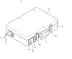
도 1은 본 발명에 의한 휴대용 공기가온기가 개방된 상태의 사시도이다.
도 2는 본 발명에 의한 휴대용 공기가온기가 폐쇄된 상태의 사시도이다.
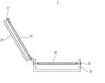
도 3은 본 발명에 의한 휴대용 공기가온기가 단열 부재를 구비하는 경우에 관한 설명도이다.
도 4는 본 발명에 의한 휴대용 공기가온기에서 하부 가열판과 상부 가열판이 케이스의 내측면으로부터 이격 배치된 경우에 관한 설명도이다.
도 5는 본 발명에 의한 휴대용 공기가온기의 케이스에 홈과 돌기가 구비되는 경우에 관한 설명도이다.
도 6은 본 발명에 의한 휴대용 공기가온기의 동작 메커니즘에 관한 설명도이다.1 is a perspective view of a portable air heater according to the present invention in an open state.
2 is a perspective view of a portable air warmer according to the present invention in a closed state.
3 is an explanatory view of a case in which a portable air warmer according to the present invention includes a heat insulating member.
4 is an explanatory view of a case in which a lower heating plate and an upper heating plate are spaced apart from an inner surface of a case in a portable air heater according to the present invention.
5 is an explanatory view of a case in which grooves and protrusions are provided in a case of a portable air warmer according to the present invention.
6 is an explanatory view of the operating mechanism of the portable air warmer according to the present invention.
이하에서는 본 발명의 구체적인 실시예에 대하여 도면을 참고하여 자세하게 설명하도록 한다.Hereinafter, specific embodiments of the present invention will be described in detail with reference to the drawings.
도 1에는 본 발명에 의한 휴대용 공기가온기(1)가 개방된 상태의 사시도가 도시되어 있고, 도 2에는 본 발명에 의한 휴대용 공기가온기(1)가 폐쇄된 상태의 사시도가 도시되어 있다.1 shows a perspective view of the portable air warmer 1 according to the present invention in an open state, and FIG. 2 shows a perspective view of the
본 발명에 의한 휴대용 공기가온기(1)는 열가소성 플라스틱을 성형하기 위하여 가열하여 연화시키는 역할을 하는 것이며, 휴대가 가능하도록 형성된다.The
본 발명에 의한 휴대용 공기가온기(1)는 케이스 본체(10), 케이스 커버(20), 하부 가열판(30), 상부 가열판(40) 및 제어부(80)를 포함하여 이루어진다.A
케이스 본체(10)와 케이스 커버(20)는 본 발명에 의한 휴대용 공기가온기(1)의 외관을 형성하는 것으로서, 케이스 본체(10)는 상부가 개방된 용기 형상으로 이루어지며, 케이스 커버(20)는 케이스 본체(10)에 힌지 결합하여 케이스 본체(10)를 개폐하는 역할을 할 수 있다. 케이스 본체(10)는 예를 들어, 횡단면의 형상이 직사각형으로 이루어질 수 있고, 케이스 커버(20)는 케이스 본체(10)의 횡단면 형상에 맞추어 횡단면이 직사각형으로 이루어질 수 있다.The
하부 가열판(30)과 상부 가열판(40)은 열가소성 플라스틱과 같은 작업 대상물을 가열하는 역할을 하는 것으로서, 전기 저항에 의해 가열될 수 있다. 하부 가열판(30)은 케이스 본체(10) 내에서 수평하게 고정되며, 상부 가열판(40)은 케이스 커버(20) 내에 상부 가열판(40)과 나란하게 고정된다. 케이스 커버(20)가 케이스 본체(10)를 폐쇄 시 하부 가열판(30)과 상부 가열판(40)은 서로 나란하게 위치하며, 하부 가열판(30)과 상부 가열판(40) 사이에는 간격이 형성되어 하부 가열판(30)과 상부 가열판(40) 사이에 작업 대상물이 위치할 수 있다.The
제어부(80)는 하부 가열판(30)과 상부 가열판(40)을 제어하는 역할을 한다. 즉, 하부 가열판(30)과 상부 가열판(40)에 대한 전기 공급을 조절하여 하부 가열판(30)과 상부 가열판(40)의 온도를 설정한 온도로 만들어줄 수 있다.The
본 발명의 휴대용 공기가온기(1)는 케이스 본체(10)에 대해 케이스 커버(20)를 회전시켜 케이스 본체(10)를 개방하고 하부 가열판(30) 위에 작업 대상물을 놓은 후 케이스 커버(20)를 덮어 하부 가열판(30)과 상부 가열판(40)의 온도를 높이는 방법으로 사용할 수 있다.In the
이러한 본 발명에 의한 휴대용 공기가온기(1)에 의하면, 작업 대상물을 가열하는 역할을 하는 하부 가열판(30)과 상부 가열판(40)이 케이스 본체(10)와 케이스 커버(20)로 이루어지는 케이스 내에 위치하기 때문에 휴대가 용이하다.According to the
또한, 가열하는 작업을 하는 중 작업 대상물이 케이스 내에 위치하여, 작업 대상물을 효과적으로 가열해주는 것이 가능하다.In addition, while the heating operation is performed, the workpiece is located in the case, and it is possible to effectively heat the workpiece.
도 3에 도시되어 있는 바와 같이, 본 발명에 의한 휴대용 공기가온기(1)는 단열부재(51)를 더 구비할 수 있다. 단열부재(51)는 케이스 본체(10)와 하부 가열판(30) 사이, 그리고 케이스 커버(20)와 상부 가열판(40) 사이에 위치한다.As shown in FIG. 3 , the
단열부재(51)는 작업 대상물의 가열시 하부 가열판(30)과 상부 가열판(40)의 열이 케이스로 전달되는 것을 방지하여, 열의 손실 없이 작업 대상물을 보다 효율적으로 가열할 수 있다.The
단열부재(51)로는 예를 들어, 광물 섬유형 단열재, 플라스틱 폼 형 단열재 등이 사용될 수 있다.As the
하부 가열판(30)과 상부 가열판(40)의 열이 케이스를 통해 외부로 빠져나가는 것을 방지하기 위한 또 다른 방법으로, 하부 가열판(30)을 케이스 본체(10)의 내측면으로부터 이격 배치하고 상부 가열판(40)을 케이스 커버(20)의 내측면으로부터 이격 배치하는 방법을 사용하는 것도 가능하다.As another method for preventing heat from the
이 경우, 도 4에 도시되어 있는 바와 같이, 하부 가열판(30)과 케이스 본체(10) 내측면 사이의 공간, 그리고 상부 가열판(40)과 케이스 커버(20) 사이의 공간에 의해, 하부 가열판(30)과 상부 가열판(40)의 열이 케이스로 전달되는 것을 방지할 수 있다.In this case, as shown in FIG. 4, the space between the
하부 가열판(30)과 상부 가열판(40)은 예를 들어, 케이스의 벽체를 관통하여 하부 가열판(30) 또는 상부 가열판(40)의 측면에 체결되는 볼트(B)에 의해 케이스의 내측면에 고정될 수 있으며, 볼트의 길이를 하부 가열판(30)과 상부 가열판(40)에 형성되는 볼트 체결 구멍의 깊이보다 길게 함으로써 하부 가열판(30)과 상부 가열판(40)을 케이스의 내측면으로부터 이격 배치되게 할 수 있다.The
볼트의 적어도 일부분은 비전도성인 플라스틱 재질로 형성하여, 볼트에 의해 하부 가열판(30)과 상부 가열판(40)의 열이 케이스로 전달되는 것을 최대한 방지할 수 있다.Since at least a portion of the bolt is formed of a non-conductive plastic material, it is possible to prevent heat from the
도 5에 도시되어 있는 바와 같이, 케이스 본체(10)의 상단 테두리와 케이스 커버(20)의 하단 테두리를 따라서는 서로 맞물리는 홈(52)과 돌기(53)가 형성될 수 있다. 도 5에서는 예를 들어, 케이스 본체(10)의 상단 테두리를 따라 돌기(53)가 형성되고 케이스 커버(20)의 하단 테두리를 따라 홈(52)이 형성된 것을 볼 수 있다.As shown in FIG. 5 ,
홈(52)과 돌기(53)는 케이스 커버(20)가 케이스 본체(10)를 폐쇄할 때 서로 맞물려 케이스 내부가 외부와 연통하게 되는 것을 방지한다. 따라서, 케이스 내의 열이 케이스 외부로 빠져나가는 것을 방지하고, 케이스 외부의 냉기가 케이스 내부로 유입되는 것을 방지할 수 있다.The
하부 가열판(30)과 상부 가열판(40)은 알루미늄 또는 스테인리스 스틸 재질로 이루어질 수 있다.The
알루미늄과 스테인리스 스틸 재질은 열을 쉽게 전달하여 하부 가열판(30)과 상부 가열판(40)이 신속하게 가열되게 할 뿐만 아니라, 높은 반사율에 의해 하부 가열판(30)과 상부 가열판(40) 사이의 열이 외부로 방사되는 것을 방지할 수 있다.The aluminum and stainless steel materials transfer heat easily, so that the
그리고 알루미늄은 경량으로 이루어져 휴대용인 본 발명의 공기가온기(1)에 적합하다.In addition, aluminum is made of lightweight and is suitable for the portable air warmer 1 of the present invention.
하부 가열판(30)과 상부 가열판(40)이 알루미늄 또는 스테인리스 스틸 재질로 이루어지는 경우, 하부 가열판(30)과 상부 가열판(40)은 저항이 높은 별도의 열선을 통해 가열될 수 있다.When the
케이스 본체(10)와 케이스 커버(20)는 난연 재질로 이루어질 수 있다.The
케이스는 하부 가열판(30)과 상부 가열판(40)으로부터 이격 배치되고 케이스와 상부 및 하부 가열판(40, 30) 사이에는 단열부재(51)가 위치할 수 있지만, 케이스 내부의 공기가 가열됨에 따라 케이스는 고온에 노출될 수 있다.The case is spaced apart from the
따라서, 케이스 본체(10)와 케이스 커버(20)를 난연 재질로 형성하여, 케이스가 고온에 의해 연소되거나 변형되는 문제를 방지하도록 하는 것이 바람직하다.Therefore, it is preferable to form the
본 발명에 의한 휴대용 공기가온기(1)는 잠금부재(60)를 더 구비할 수 있다.The portable air warmer 1 according to the present invention may further include a locking
잠금부재(60)는 케이스 커버(20)가 케이스 본체(10)를 폐쇄시, 케이스 커버(20)를 케이스 커버(20)에 대해 고정하는 역할을 한다.The locking
이에 따라, 작업 대상물의 가열시 케이스 내부가 확실하게 밀폐된 상태를 유지할 수 있고, 본 발명에 의한 휴대용 공기가온기(1)를 운반시 케이스가 열리어 운반 작업이 불편해지는 것을 방지할 수 있다.Accordingly, when the work object is heated, the inside of the case can be reliably maintained in a sealed state, and when the
본 발명에 의한 휴대용 공기가온기(1)는 개방각 제한부재(70)를 더 구비할 수 있다.The portable air warmer 1 according to the present invention may further include an opening angle limiting member 70 .
개방각 제한부재(70)는 케이스 본체(10)에 대한 케이스 커버(20)의 개방 각도를 제한하는 역할을 한다. 예를 들어, 개방각 제한부재(70)는 케이스가 개방되었을 때 케이스 커버(20)가 케이스 본체(10)에 대해 90 ~ 110°정도까지만 열릴 수 있도록 한다.The opening angle limiting member 70 serves to limit the opening angle of the case cover 20 with respect to the
이에 따라, 본 발명에 의한 휴대용 공기가온기(1) 상에 작업 대상물을 올려두거나 제거하기 위하여 케이스 커버(20)를 개방할 때 케이스 커버(20)가 완전히 열리지 않으므로, 제한된 크기의 공간에서 본 발명에 의한 휴대용 공기가온기(1)를 사용하는 것이 가능하다.Accordingly, when the case cover 20 is opened to place or remove a work object on the
개방각 제한부재(70)는 예를 들어, 일단부가 케이스 본체(10)의 내측면에 힌지 결합하는 제1 링크(71), 일단부가 제1 링크(71)의 타단부에 힌지 결합하고 타단부가 케이스 커버(20)의 내측면에 힌지 결합하는 제2 링크(72)로 이루어질 수 있다. 제1 링크(71)와 제2 링크(72)는 케이스 본체(10)와 케이스 커버(20)가 90 ~ 110°를 이루는 상태에서 서로 일자형에 가깝게 배치되어 각도가 최대가 됨으로써 케이스 본체(10)에 대해 케이스 커버(20)가 더 이상 펼쳐지지 않도록 한다. 그리고 케이스가 닫히는 경우에는 제1 링크(71)와 제2 링크(72) 사이의 각도가 줄어들면서 접히어 케이스가 닫히는 것을 방해하지 않는다.The opening angle limiting member 70 is, for example, a
하부 가열판(30)과 상부 가열판(40)은 서로 전기적으로 연결되어, 함께 온도가 조절될 수 있다.The
하부 가열판(30)과 상부 가열판(40)을 전기적으로 연결하는 연결선(w)은 케이스의 개폐에 관계없이 하부 가열판(30)과 상부 가열판(40)을 연결할 수 있도록 케이스가 열렸을 때 하부 가열판(30)과 상부 가열판(40) 사이의 간격보다 길게 형성된다.The connection line (w) electrically connecting the
제어부(80)는 설정부(81)와 디스플레이부(82)를 구비할 수 있다.The
설정부(81)는 하부 가열판(30)과 상부 가열판(40)의 동작을 설정하기 위한 것으로서, 구체적으로는 하부 가열판(30)과 상부 가열판(40)의 목표 가열 온도, 가열 패턴 등을 설정할 수 있다. 설정부(81)에서 설정된 정보에 따라 제어부(80)는 하부 가열판(30)과 상부 가열판(40)을 제어할 수 있다.The setting
그리고 디스플레이부(82)는 설정부(81)의 설정 상태, 하부 가열판(30)과 상부 가열판(40)의 동작 상태를 표시하는 역할을 한다. 디스플레이부(82)는 또한, 휴대용 공기가온기(1)에 대한 전원 공급 유무, 에러 유무 등을 표시해줄 수 있다.The
이러한 설정부(81)와 디스플레이부(82)에 의해 작업 대상물에 대해 원하는 작업을 정확하게 수행하는 것이 가능하다.With the setting
설정부(81)와 디스플레이부(82)는 케이스 본체(10) 또는 케이스 커버(20)의 외측면에 배치될 수 있다. 이에 따라, 케이스가 닫힌 상태에서도 쉽게 하부 가열판(30)과 상부 가열판(40)의 상태를 확인하면서 설정을 바꾸어줄 수 있다.The setting
설정부(81)는 예를 들어 온도설정 버튼과 전원버튼을 구비할 수 있다.The setting
온도설정 버튼은 상부 및 하부 가열판(40, 30)의 희망 가열 온도를 설정할 때 사용하는 것으로서, 설정 온도를 높이는 업 버튼과 설정 온도를 낮추는 다운 버튼을 구비한다. 온도설정 버튼으로 희망 가열 온도를 설정한 후 동작을 멈추고 약 3초 가량이 지나면 온도설정이 종료될 수 있다.The temperature setting button is used to set desired heating temperatures of the upper and
전원버튼은 설정부(81)의 전원을 온-오프시킬 수 있다. 예를 들어, 오프 상태에서 전원버튼을 누르면 설정부(81)가 온 상태가 되고, 온 상태에서 전원버튼을 누르면 설정부(81)가 오프 상태가 될 수 있다.The power button may turn on/off the power of the
전원버튼은 또한 온도설정 상태를 초기화할 수 있다. 예를 들어, 전원버튼을 10초 이상 길게 누르면 온도설정 상태가 초기화될 수 있다.The power button can also reset the temperature setting state. For example, if the power button is pressed and held for 10 seconds or more, the temperature setting state may be initialized.
디스플레이부(82)는 예를 들어 셋(Set) 램프, 런(Run) 램프 및 온도표시부를 구비할 수 있다.The
셋 램프는 온도설정 상태 등과 같이 셋팅 상태인 경우 점등되며, 셋팅 상태가 종료되면 꺼질 수 있다.The set lamp is turned on in the setting state, such as the temperature setting state, and can be turned off when the setting state is finished.
런 램프는 상부 및 하부 가열판(40, 30)이 가동되고 있는 상태에서는 커지며, 상부 및 하부 가열판(40, 30)에 전원이 공급되지 않으면 꺼질 수 있다.The run lamp increases when the upper and
그리고 온도표시부에는 온도가 표시된다. 설정부(81)가 온도설정 상태인 경우에는 온도표시부에 설정 온도가 표시되고, 그렇지 않은 경우에는 상부 및 하부 가열판(40, 30)의 현재 온도가 표시될 수 있다.And the temperature is displayed on the temperature display unit. When the
제어부(80)는 센서(미도시)를 더 구비하여 하부 가열판(30)과 상부 가열판(40)의 온도를 측정할 수 있다. 센서에 의해 측정된 온도는 제어부(80)가 하부 가열판(30)과 상부 가열판(40)의 동작을 제어하는 데 이용될 수 있다. 즉, 측정된 온도가 설정 온도보다 낮은 경우에 제어부(80)는 계속해서 전원을 공급하여 하부 가열판(30)과 상부 가열판(40)의 온도를 높이고, 측정된 온도가 설정 온도보다 높은 경우에 제어부(80)는 전원을 차단하여 하부 가열판(30)과 상부 가열판(40)의 온도를 낮출 수 있다.The
센서를 통해 측정된 하부 가열판(30)과 상부 가열판(40)의 온도는 디스플레이부(82)를 통해 표시될 수 있다.The temperatures of the
제어부(80)는 타이머(미도시)를 더 구비할 수 있다. 타이머를 구비하는 경우, 상부 및 하부 가열판(40, 30)은 설정한 시간 간격으로 전원을 공급받을 수 있다.The
설정부(81)는 구체적으로 아래와 같이 센서와 타이머의 동작을 설정할 수 있다.The setting
예를 들어, 설정부(81)의 전원이 켜진 상태에서 업 버튼과 다운 버튼을 동시에 약 3초 정도 누르면 설정 모드가 되고 디스플레이부(82)에는 'tn'이라는 글자가 표시될 수 있다. 이 상태에서 업 버튼을 누르면 센서의 동작을 설정하는 모드와 타이머의 동작을 설정하는 모드로 순서대로 전환될 수 있다. 센서의 동작을 설정하는 모드에서는 디스플레이부(82)에 'En'이라는 글자가 표시되고, 타이머의 동작을 설정하는 모드에서는 디스플레이부(82)에 'In'이라는 글자가 표시될 수 있다.For example, in a state in which the power of the
그리고 센서의 동작을 설정하는 모드에서 업 버튼과 다운 버튼을 동시에 눌러주면 센서의 동작을 설정하는 모드의 세부 설정 모드로 진입할 수 있다. 그리고 업 버튼과 다운 버튼을 동시에 누를 때마다 예를 들어 아래 [표 1]의 순서대로 다음 단계의 설정 모드로 전환될 수 있다. 마지막 단계까지 설정이 완료되면 디스플레이부(82)에 'AU'가 약 3회 정도 깜빡이며 설정값이 저장될 수 있다.In addition, if the up button and the down button are pressed simultaneously in the mode for setting the operation of the sensor, a detailed setting mode of the mode for setting the operation of the sensor may be entered. In addition, each time the up button and the down button are pressed at the same time, for example, it can be converted to the setting mode of the next step in the order of [Table 1] below. When the setting up to the last step is completed, 'AU' blinks about three times on the

타이머의 동작을 설정하는 모드에서 업 버튼과 다운 버튼을 동시에 눌러주면 타이머의 동작을 설정하는 모드의 세부 설정 모드로 진입할 수 있다. 그리고 업 버튼 또는 다운 버튼을 눌러 예를 들어 아래 [표 2]와 같이 단계별로 지정된 타이머의 동작 주기를 선택할 수 있다. 희망하는 타이머의 동작 주기에서 업 버튼과 다운 버튼을 동시에 눌러주면 디스플레이부(82)에 'AU'가 약 3회 정도 깜빡이며 설정값이 저장될 수 있다.If you press the up and down buttons at the same time in the mode for setting the operation of the timer, you can enter the detailed setting mode of the mode for setting the operation of the timer. And, by pressing the up button or the down button, for example, as shown in [Table 2] below, it is possible to select the operation cycle of the timer designated for each step. If the up button and the down button are simultaneously pressed at a desired timer operation cycle, 'AU' blinks about three times on the

본 발명에 의한 휴대용 공기가온기(1)의 안전한 동작을 위해, 센서의 단선시 제어부(80)는 소정 시간마다 하부 가열판(30)과 상부 가열판(40)을 온-오프 시키는 방법으로 제어할 수 있다.For the safe operation of the
센서가 단선되는 경우는 단순히 센서를 통해 하부 가열판(30)과 상부 가열판(40)의 온도를 얻을 수 없는 상태이므로, 본 발명에 의한 휴대용 공기가온기(1)의 동작을 계속해서 진행하되 하부 가열판(30)과 상부 가열판(40)이 최대한 설정한 온도가 될 수 있도록 소정 시간마다 하부 가열판(30)과 상부 가열판(40)을 온-오프 시킨다.When the sensor is disconnected, the temperature of the
설정 온도에 따라서 하부 가열판(30)과 상부 가열판(40)이 온-오프되는 시간 간격은 타이머를 이용해 미리 설정 및 저장해둘 수 있다.The time interval at which the
센서의 단선시 디스플레이부(82)에는 '10'이라는 글자가 표시될 수 있다.When the sensor is disconnected, the character '10' may be displayed on the
센서의 합선시 제어부(80)는 하부 가열판(30)과 상부 가열판(40)에 대한 전원 공급을 차단할 수 있다.When a sensor is short-circuited, the
센서가 합선된 경우에는 본 발명에 의한 휴대용 공기가온기(1)의 다른 구성에도 고장이 발생할 수 있기 때문에 하부 가열판(30)과 상부 가열판(40)에 대한 전원 공급을 차단하는 것이 바람직하다.If the sensor is short-circuited, it is preferable to cut off the power supply to the
센서에 합선이 발생한 경우에는 또한 디스플레이부(82)에 에러 표시를 할 수 있다.When a short circuit occurs in the sensor, an error display may also be displayed on the
센서의 합선시 디스플레이부(82)에는 'ES'라는 글자가 표시될 수 있다.When the sensor is short-circuited, 'ES' may be displayed on the
센서가 하부 가열판(30) 또는 상부 가열판(40)이 소정 온도 이상인 것을 감지시, 제어부(80)는 하부 가열판(30)과 상부 가열판(40)에 대한 전원 공급을 차단할 수 있다. 소정 온도는 본 발명에 의한 휴대용 공기가온기(1)에 고장이 발생할 수 있는 온도보다 낮은 온도로 미리 설정될 수 있다.When the sensor detects that the temperature of the
이 경우, 하부 가열판(30)과 상부 가열판(40)의 오작동에 의해 본 발명에 의한 휴대용 공기가온기(1)가 가열되어 고장이 발생하는 것을 방지할 수 있다.In this case, malfunction of the
센서가 하부 가열판(30) 또는 상부 가열판(40)의 과열을 감지한 경우에는 디스플레이부(82)에 에러 표시가 될 수 있다.When the sensor detects overheating of the
과열시 디스플레이부(82)에는 'Ht'라는 글자가 표시될 수 있다.In case of overheating, the
본 발명에 의한 휴대용 공기가온기(1)는 상기한 것과 같은 구성 외에도, 제어부(80), 하부 가열판(30) 및 상부 가열판(40)에 전원을 공급해주기 위한 전원 공급부(s), 그리고 휴대성을 높여줄 수 있도록 케이스 본체(10)의 외측면에 형성되는 손잡이(h) 등의 구성을 더 구비할 수 있다.In addition to the configuration described above, the
하기 [표 3]에는 위에서 설명한 본 발명에 의한 휴대용 공기가온기(1)의 예시적인 스펙이 나타나 있다. [표 3]에 나타난 스펙은 예시적인 것이므로, 휴대용 공기가온기(1)의 작업 대상물, 가격 등에 맞추어 적절하게 변경될 수 있다.Table 3 below shows exemplary specifications of the

위에서 설명한 본 발명에 의한 휴대용 공기가온기(1)의 동작 메커니즘을 정리하면 아래와 같다. 도 6에는 본 발명에 의한 휴대용 공기가온기(1)의 동작 메커니즘에 관한 설명도가 도시되어 있다.The operation mechanism of the
전원 공급부(s)를 콘센트 등에 연결하면 본 발명에 의한 휴대용 공기가온기(1)에 전원이 공급된다. 그 후 설정부(81)의 전원을 키고 희망 온도의 설정을 완료하면 상부 및 하부 가열판(40, 30)이 가열된다. 상부 및 하부 가열판(40, 30)이 설정한 온도에 도달하면 온도가 유지되고, 본 발명에 의한 휴대용 공기가온기(1)의 사용이 완료되면 전원을 공급을 해제한다.When the power supply unit s is connected to an outlet or the like, power is supplied to the
만약, 상부 및 하부 가열판(40, 30)이 과열된 것이 감지되면 휴대용 공기가온기(1)에 대한 전원 공급을 차단할 수 있다. 전원은 예를 들어, 바이메탈을 이용해 차단할 수 있다.If it is detected that the upper and
그리고 휴대용 공기가온기(1)에 누전이 발생한 경우에도 전원 공급을 차단할 수 있다. 누전에 따른 전원 공급 차단은 예를 들어, 퓨즈를 이용하여 진행할 수 있다.In addition, even when a short circuit occurs in the
본 발명의 권리범위는 상술한 실시예에 한정되는 것이 아니라 첨부된 특허청구범위 내에서 다양한 형태의 실시예로 구현될 수 있다. 특허청구범위에서 청구하는 본 발명의 요지를 벗어남이 없이 당해 발명이 속하는 기술 분야에서 통상의 지식을 가진 자라면 누구든지 변형 가능한 다양한 범위까지 본 발명의 청구범위 기재의 범위 내에 있는 것으로 본다.The scope of the present invention is not limited to the above-described embodiments, but may be implemented in various forms of embodiments within the scope of the appended claims. Anyone with ordinary knowledge in the art to which the invention pertains without departing from the subject matter of the invention claimed in the claims is considered to be within the scope of the claims of the present invention to various extents that can be modified.
1 : 휴대용 공기가온기
10 : 케이스 본체20 : 케이스 커버
30 : 하부 가열판40 : 상부 가열판
51 : 단열부재52 : 홈
53 : 돌기60 : 잠금부재
70 : 개방각 제한부재80 : 제어부
81 : 설정부82 : 디스플레이부1 : Portable air warmer
10: case body 20: case cover
30: lower heating plate 40: upper heating plate
51: insulation member 52: groove
53: protrusion 60: locking member
70: opening angle limiting member 80: control unit
81: setting unit 82: display unit
Claims (15)
Translated fromKorean상기 케이스 본체에 힌지 결합하여 상기 케이스 본체를 개폐하는 케이스 커버;
상기 케이스 본체 내에 고정되는 하부 가열판;
상기 케이스 커버 내에 고정되며, 상기 케이스 커버가 상기 케이스 본체를 폐쇄시 상기 하부 가열판과 나란하게 위치하는 상부 가열판; 및
상기 하부 가열판과 상기 상부 가열판을 제어하는 제어부;를 포함하며,
상기 케이스 본체와 상기 하부 가열판 사이, 상기 케이스 커버와 상기 상부 가열판 사이에는 단열부재가 배치되고,
상기 케이스 본체의 상단 테두리와 상기 케이스 커버의 하단 테두리를 따라 서는 서로 맞물리는 홈과 돌기가 형성되며,
상기 하부 가열판은 상기 케이스 본체의 내측면으로부터 이격 배치되고, 상기 상부 가열판은 상기 케이스 커버의 내측면으로부터 이격 배치되고,
상기 케이스 본체에는 상기 케이스 본체에 대한 상기 케이스 커버의 개방 각도를 제한하는 개방각 제한부재(70)를 포함하며,
상기 개방각 제한부재(70)는, 일단부가 케이스 본체(10)의 내측면에 힌지 결합하는 제1 링크(71); 및
상기 일단부가 제1 링크(71)의 타단부에 힌지 결합하고 타단부는 케이스 커버(20)의 내측면에 힌지 결합하는 제2 링크(72);로 이루어지고,
상기 제1 링크(71)와 제2 링크(72)는 케이스 본체(10)와 케이스 커버(20)가 최대 90 ~ 110°의 각도를 이루는 상태를 유지하며,
상기 제어부는, 상기 하부 가열판과 상기 상부 가열판의 동작을 설정하기 위한 설정부; 및 상기 설정부의 설정 상태, 상기 하부 가열판과 상기 상부 가열판의 동작 상태를 표시하는 디스플레이부;를 구비하고,
상기 설정부와 상기 디스플레이부는 상기 케이스 본체 또는 상기 케이스 커버의 외측면에 배치되고,
상기 하부 가열판과 상기 상부 가열판의 동작을 위한 온도 범위는 0℃ 내지 80℃이며,
상기 설정부의 센서와 타이머 설정을 위한 동작은
i) 설정부(81)의 전원이 켜진 상태에서 업 버튼과 다운 버튼을 동시에 3초 눌러 설정 모드를 형성하고, 이때 디스플레이부(82)에는 ‘tn’이라는 글자가 표시되고,
ii) 상기 디스플레이부(82)의 ‘tn’ 상태에서 업 버튼을 눌러 센서의 동작을 설정하는 모드; 및 타이머의 동작을 설정하는 모드;로 순서대로 전환하며,
상기 센서의 동작을 설정하는 모드에서는 디스플레이부(82)에 'En'이라는 글자가 표시되고, 상기 타이머의 동작을 설정하는 모드에서는 디스플레이부(82)에 'In'이라는 글자가 표시되고,
iii) 상기 디스플레이부(82)의 'En' 상태에서의 센서 동작은 업 버튼과 다운 버튼을 동시에 눌러주어 센서의 동작을 설정하는 모드의 세부 설정 모드인 최저온도설정, 최고온도설정, 온도편차설정, 출력지연시간, 과승온도설정, 보정온도설정의 순서로 설정하며,
iv) 상기 보정온도설정이 완료되면 디스플레이부(82)에는 'AU'가 3회 정도 깜빡이며 설정값이 저장되며,
상기 최저온도설정은 최저온도 범위의 설정을 위한 것으로서, 기본설정 0℃를 기준으로 0℃ ~ 최고온도 이하의 범위를 가지고,
상기 최고온도설정은 최고온도 범위의 설정을 위한 것으로서, 기본설정 60℃를 기준으로 최저온도 이상 ~ 99℃의 범위를 가지며,
상기 온도편차설정은 동작 시작에 필요한 상기 최저 또는 최고 설정온도와 현재 온도와의 차이온도 설정을 위한 것으로서, 기본설정 2℃를 기준으로 0℃ ~ 5℃의 범위를 가지고,
상기 출력지연시간은 ON의 작동 시 지연시간만큼 실질적으로 작동이 지연되는 시간의 설정을 위한 것으로서, 기본설정 20초를 기준으로 1 ~ 60초의 범위를 가지며,
상기 과승온도설정은 센서 감지온도가 에러 표시를 표시하는 온도의 설정을 위한 것으로서, 기본설정 80℃를 기준으로 최고온도 이상 ~ 99℃의 범위를 가지고,
상기 보정온도설정은 실제 온도와 센서 감지온도와 차이가 있는 경우 보정하는 온도 범위를 설정한 것으로서, 기본설정 0℃를 기준으로 -9℃ ~ 10℃이며,
상기의 i) 내지 iv)의 순서와 같이 이루어지며,
열가소성 플라스틱 소재의 가열을 위한 부목 성형용 휴대용 공기가온기는, 85V AC 내지 265V AC의 정격전압; 전자식의 구동방식; 2kw의 최대 출력;을 포함하는 전원을 구비하고,
상기 휴대용 공기가온기의 동작을 위한 가온속도는 30초당 1℃이며,
상기 센서의 25℃의 정격저항이 25℃/5K인 것을 특징으로 하는,
열가소성 플라스틱 소재의 가열을 위한 부목 성형용 휴대용 공기가온기.A container-shaped case body with an open top;
a case cover hinged to the case body to open and close the case body;
a lower heating plate fixed within the case body;
an upper heating plate fixed within the case cover and positioned parallel to the lower heating plate when the case cover closes the case body; and
And a control unit for controlling the lower heating plate and the upper heating plate,
A heat insulating member is disposed between the case body and the lower heating plate and between the case cover and the upper heating plate,
Grooves and protrusions engaging each other are formed along the upper edge of the case body and the lower edge of the case cover,
The lower heating plate is spaced apart from the inner surface of the case body, and the upper heating plate is spaced apart from the inner surface of the case cover.
The case body includes an opening angle limiting member 70 for limiting an opening angle of the case cover with respect to the case body,
The opening angle limiting member 70 includes a first link 71 having one end hinged to the inner surface of the case body 10; and
A second link 72 having one end hinged to the other end of the first link 71 and the other end hinged to the inner surface of the case cover 20;
The first link 71 and the second link 72 maintain a state in which the case body 10 and the case cover 20 form an angle of up to 90 to 110 °,
The control unit may include a setting unit for setting operations of the lower heating plate and the upper heating plate; And a display unit for displaying the setting state of the setting unit and the operation state of the lower heating plate and the upper heating plate;
The setting unit and the display unit are disposed on an outer surface of the case body or the case cover,
The temperature range for the operation of the lower heating plate and the upper heating plate is 0 ° C to 80 ° C,
The operation for setting the sensor and timer of the setting unit is
i) With the power of the setting unit 81 turned on, press the up button and the down button simultaneously for 3 seconds to form a setting mode, and at this time, the display unit 82 displays the word 'tn',
ii) a mode in which the operation of the sensor is set by pressing the up button in the 'tn' state of the display unit 82; And a mode for setting the operation of the timer; to switch in order,
In the mode for setting the operation of the sensor, the letter 'En' is displayed on the display unit 82, and in the mode for setting the operation of the timer, the letter 'In' is displayed on the display unit 82,
iii) The sensor operation in the 'En' state of the display unit 82 is a detailed setting mode of the mode in which the operation of the sensor is set by pressing the up button and the down button simultaneously, minimum temperature setting, maximum temperature setting, and temperature deviation setting , output delay time, overheating temperature setting, correction temperature setting in order.
iv) When the correction temperature setting is completed, 'AU' blinks about 3 times on the display unit 82 and the set value is stored.
The minimum temperature setting is for setting the minimum temperature range, and has a range of 0 ° C to less than the maximum temperature based on the basic setting 0 ° C,
The maximum temperature setting is for setting the maximum temperature range, and has a range of from the minimum temperature to 99 ° C based on the basic setting of 60 ° C,
The temperature deviation setting is for setting the difference temperature between the minimum or maximum set temperature and the current temperature required for operation start, and has a range of 0 ° C to 5 ° C based on the basic setting of 2 ° C,
The output delay time is for setting the time for which the operation is substantially delayed by the delay time when ON is operated, and has a range of 1 to 60 seconds based on the default setting of 20 seconds,
The overheating temperature setting is for setting the temperature at which the sensor detected temperature displays an error display, and has a range of from the maximum temperature to 99 ° C based on the default setting of 80 ° C,
The correction temperature setting is to set the temperature range to be corrected when there is a difference between the actual temperature and the sensor detected temperature, and is -9 ℃ to 10 ℃ based on the default setting of 0 ℃,
It is made in the order of i) to iv) above,
The portable air heater for forming a splint for heating thermoplastic materials has a rated voltage of 85V AC to 265V AC; electronic driving method; A maximum output of 2 kw; having a power source including,
The heating rate for the operation of the portable air warmer is 1 ° C per 30 seconds,
Characterized in that the rated resistance of the sensor at 25 ° C is 25 ° C / 5K,
Portable air warmer for molding splints for heating thermoplastic materials.
상기 케이스 본체와 상기 케이스 커버는 난연 재질로 이루어지는 것을 특징으로 하는, 열가소성 플라스틱 소재의 가열을 위한 부목 성형용 휴대용 공기가온기.According to claim 1,
The case body and the case cover are made of a flame retardant material, a portable air heater for molding a splint for heating a thermoplastic material.
상기 하부 가열판과 상기 상부 가열판은 알루미늄 또는 스테인리스 스틸로 이루어지는 것을 특징으로 하는, 열가소성 플라스틱 소재의 가열을 위한 부목 성형용 휴대용 공기가온기.According to claim 1,
The lower heating plate and the upper heating plate are made of aluminum or stainless steel, a portable air heater for forming a splint for heating a thermoplastic material.
상기 케이스 커버가 상기 케이스 본체를 폐쇄시, 상기 케이스 커버를 상기 케이스 본체에 대해 고정하는 잠금부재를 더 포함하는 것을 특징으로 하는, 열가소성 플라스틱 소재의 가열을 위한 부목 성형용 휴대용 공기가온기.According to claim 1,
The portable air heater for forming a splint for heating a thermoplastic material, characterized in that it further comprises a locking member for fixing the case cover to the case body when the case cover closes the case body.
상기 하부 가열판과 상기 상부 가열판은 서로 전기적으로 연결되며, 상기 전기적 연결은 케이스 내부에 위치하는 연결선(w)인 것을 특징으로 하는, 열가소성 플라스틱 소재의 가열을 위한 부목 성형용 휴대용 공기가온기.According to claim 1,
The lower heating plate and the upper heating plate are electrically connected to each other, and the electrical connection is a portable air heater for molding a splint for heating a thermoplastic material, characterized in that the connection line (w) located inside the case.
상기 제어부는 상기 하부 가열판과 상기 상부 가열판의 온도를 측정하는 센서를 구비하며,
상기 센서의 단선 시, 상기 제어부는 소정 시간마다 상기 하부 가열판과 상기 상부 가열판을 온-오프 시키고,
상기 센서의 합선 시, 상기 제어부는 상기 하부 가열판과 상기 상부 가열판에 대한 전원 공급을 차단하며,
상기 센서가 상기 하부 가열판 또는 상기 상부 가열판이 소정 온도 이상인 것을 감지 시, 상기 제어부는 상기 하부 가열판과 상기 상부 가열판에 대한 전원 공급을 차단하고,
상기 소정 온도는 99℃인 것을 특징으로 하는, 열가소성 플라스틱 소재의 가열을 위한 부목 성형용 휴대용 공기가온기.
According to claim 1,
The control unit has a sensor for measuring the temperature of the lower heating plate and the upper heating plate,
When the sensor is disconnected, the control unit turns on and off the lower heating plate and the upper heating plate at predetermined time intervals,
When the sensor is short-circuited, the control unit cuts off power supply to the lower heating plate and the upper heating plate,
When the sensor detects that the lower heating plate or the upper heating plate has a temperature higher than a predetermined temperature, the controller cuts off power supply to the lower heating plate and the upper heating plate;
Characterized in that the predetermined temperature is 99 ° C, a portable air heater for molding a splint for heating a thermoplastic material.
Priority Applications (1)
| Application Number | Priority Date | Filing Date | Title |
|---|---|---|---|
| KR1020210080504AKR102492096B1 (en) | 2021-06-22 | 2021-06-22 | Portable air heater |
Applications Claiming Priority (1)
| Application Number | Priority Date | Filing Date | Title |
|---|---|---|---|
| KR1020210080504AKR102492096B1 (en) | 2021-06-22 | 2021-06-22 | Portable air heater |
Publications (2)
| Publication Number | Publication Date |
|---|---|
| KR20220170003A KR20220170003A (en) | 2022-12-29 |
| KR102492096B1true KR102492096B1 (en) | 2023-01-26 |
Family
ID=84539528
Family Applications (1)
| Application Number | Title | Priority Date | Filing Date |
|---|---|---|---|
| KR1020210080504AActiveKR102492096B1 (en) | 2021-06-22 | 2021-06-22 | Portable air heater |
Country Status (1)
| Country | Link |
|---|---|
| KR (1) | KR102492096B1 (en) |
Cited By (1)
| Publication number | Priority date | Publication date | Assignee | Title |
|---|---|---|---|---|
| WO2025100637A1 (en)* | 2023-11-07 | 2025-05-15 | 허승욱 | Orthopedic splint heating device |
Citations (2)
| Publication number | Priority date | Publication date | Assignee | Title |
|---|---|---|---|---|
| JP2006035566A (en)* | 2004-07-26 | 2006-02-09 | Toshiba Corp | Image erasing device |
| WO2008078105A2 (en)* | 2006-12-22 | 2008-07-03 | Benjamin Chang | A splinting or immobilisation device |
Family Cites Families (1)
| Publication number | Priority date | Publication date | Assignee | Title |
|---|---|---|---|---|
| US9872795B2 (en) | 2014-03-12 | 2018-01-23 | Rechargeable Battery Corporation | Thermoformable medical member with heater and method of manufacturing same |
- 2021
- 2021-06-22KRKR1020210080504Apatent/KR102492096B1/enactiveActive
Patent Citations (2)
| Publication number | Priority date | Publication date | Assignee | Title |
|---|---|---|---|---|
| JP2006035566A (en)* | 2004-07-26 | 2006-02-09 | Toshiba Corp | Image erasing device |
| WO2008078105A2 (en)* | 2006-12-22 | 2008-07-03 | Benjamin Chang | A splinting or immobilisation device |
Cited By (1)
| Publication number | Priority date | Publication date | Assignee | Title |
|---|---|---|---|---|
| WO2025100637A1 (en)* | 2023-11-07 | 2025-05-15 | 허승욱 | Orthopedic splint heating device |
Also Published As
| Publication number | Publication date |
|---|---|
| KR20220170003A (en) | 2022-12-29 |
Similar Documents
| Publication | Publication Date | Title |
|---|---|---|
| US6427581B1 (en) | Waffle maker with cooking temperature control | |
| KR102492096B1 (en) | Portable air heater | |
| US6172335B1 (en) | Carpet seaming iron with electronic temperature control | |
| KR100411548B1 (en) | Cooking apparatus | |
| KR102161358B1 (en) | induction cooker with double safety structure | |
| US6489596B2 (en) | Quantitative cooking device | |
| KR101742626B1 (en) | A soldering iron with a solder supply device | |
| KR20100127590A (en) | Hair iron and control method | |
| CN210248830U (en) | Depilatory wax machine for melting depilatory wax | |
| JP2008025959A (en) | Electric heater | |
| KR200281009Y1 (en) | Plug with controller | |
| KR101932013B1 (en) | Electric cooker | |
| GB2007046A (en) | Electric water heaters | |
| KR101017171B1 (en) | Electric oven and its operation method | |
| JP2000023855A (en) | Electric cooker | |
| KR20060082267A (en) | Oven range with heating drawer and control method | |
| CN2839338Y (en) | Electric iron steam controller | |
| CN208319020U (en) | A kind of cooking device with end flue temperature protective device | |
| JP2841051B2 (en) | Tape welding equipment | |
| JPH0527833Y2 (en) | ||
| KR910002672Y1 (en) | Grill heater driving circuit of oven | |
| JPS5924012Y2 (en) | Electric air heater for eyeglass frames | |
| KR0143208B1 (en) | Cord less iron | |
| US9950470B1 (en) | Linear heat seal device | |
| KR100437408B1 (en) | A circuit for overheating prevention of gas oven range |
Legal Events
| Date | Code | Title | Description |
|---|---|---|---|
| PA0109 | Patent application | Patent event code:PA01091R01D Comment text:Patent Application Patent event date:20210622 | |
| PA0201 | Request for examination | ||
| PE0902 | Notice of grounds for rejection | Comment text:Notification of reason for refusal Patent event date:20220620 Patent event code:PE09021S01D | |
| E90F | Notification of reason for final refusal | ||
| PE0902 | Notice of grounds for rejection | Comment text:Final Notice of Reason for Refusal Patent event date:20221209 Patent event code:PE09021S02D | |
| PG1501 | Laying open of application | ||
| E701 | Decision to grant or registration of patent right | ||
| PE0701 | Decision of registration | Patent event code:PE07011S01D Comment text:Decision to Grant Registration Patent event date:20230117 | |
| GRNT | Written decision to grant | ||
| PR0701 | Registration of establishment | Comment text:Registration of Establishment Patent event date:20230119 Patent event code:PR07011E01D | |
| PR1002 | Payment of registration fee | Payment date:20230119 End annual number:3 Start annual number:1 | |
| PG1601 | Publication of registration |