KR102488750B1 - camera module - Google Patents
camera moduleDownload PDFInfo
- Publication number
- KR102488750B1 KR102488750B1KR1020210010811AKR20210010811AKR102488750B1KR 102488750 B1KR102488750 B1KR 102488750B1KR 1020210010811 AKR1020210010811 AKR 1020210010811AKR 20210010811 AKR20210010811 AKR 20210010811AKR 102488750 B1KR102488750 B1KR 102488750B1
- Authority
- KR
- South Korea
- Prior art keywords
- optical axis
- lens
- support structure
- module
- camera module
- Prior art date
- Legal status (The legal status is an assumption and is not a legal conclusion. Google has not performed a legal analysis and makes no representation as to the accuracy of the status listed.)
- Active
Links
- 230000003287optical effectEffects0.000claimsabstractdescription71
- 238000003384imaging methodMethods0.000claimsdescription5
- 239000000758substrateSubstances0.000description4
- 230000006866deteriorationEffects0.000description2
- 230000002265preventionEffects0.000description2
- 230000015572biosynthetic processEffects0.000description1
- 230000003139buffering effectEffects0.000description1
- 230000003247decreasing effectEffects0.000description1
- 239000013013elastic materialSubstances0.000description1
- 238000001914filtrationMethods0.000description1
- 230000003993interactionEffects0.000description1
- 238000010295mobile communicationMethods0.000description1
- 238000005096rolling processMethods0.000description1
- 229910052710siliconInorganic materials0.000description1
- 239000010703siliconSubstances0.000description1
- 230000000087stabilizing effectEffects0.000description1
Images


Classifications
- G—PHYSICS
- G03—PHOTOGRAPHY; CINEMATOGRAPHY; ANALOGOUS TECHNIQUES USING WAVES OTHER THAN OPTICAL WAVES; ELECTROGRAPHY; HOLOGRAPHY
- G03B—APPARATUS OR ARRANGEMENTS FOR TAKING PHOTOGRAPHS OR FOR PROJECTING OR VIEWING THEM; APPARATUS OR ARRANGEMENTS EMPLOYING ANALOGOUS TECHNIQUES USING WAVES OTHER THAN OPTICAL WAVES; ACCESSORIES THEREFOR
- G03B17/00—Details of cameras or camera bodies; Accessories therefor
- G03B17/02—Bodies
- G03B17/17—Bodies with reflectors arranged in beam forming the photographic image, e.g. for reducing dimensions of camera
- G—PHYSICS
- G03—PHOTOGRAPHY; CINEMATOGRAPHY; ANALOGOUS TECHNIQUES USING WAVES OTHER THAN OPTICAL WAVES; ELECTROGRAPHY; HOLOGRAPHY
- G03B—APPARATUS OR ARRANGEMENTS FOR TAKING PHOTOGRAPHS OR FOR PROJECTING OR VIEWING THEM; APPARATUS OR ARRANGEMENTS EMPLOYING ANALOGOUS TECHNIQUES USING WAVES OTHER THAN OPTICAL WAVES; ACCESSORIES THEREFOR
- G03B17/00—Details of cameras or camera bodies; Accessories therefor
- G03B17/02—Bodies
- G03B17/04—Bodies collapsible, foldable or extensible, e.g. book type
- G—PHYSICS
- G03—PHOTOGRAPHY; CINEMATOGRAPHY; ANALOGOUS TECHNIQUES USING WAVES OTHER THAN OPTICAL WAVES; ELECTROGRAPHY; HOLOGRAPHY
- G03B—APPARATUS OR ARRANGEMENTS FOR TAKING PHOTOGRAPHS OR FOR PROJECTING OR VIEWING THEM; APPARATUS OR ARRANGEMENTS EMPLOYING ANALOGOUS TECHNIQUES USING WAVES OTHER THAN OPTICAL WAVES; ACCESSORIES THEREFOR
- G03B17/00—Details of cameras or camera bodies; Accessories therefor
- G03B17/02—Bodies
- G03B17/12—Bodies with means for supporting objectives, supplementary lenses, filters, masks, or turrets
- G—PHYSICS
- G03—PHOTOGRAPHY; CINEMATOGRAPHY; ANALOGOUS TECHNIQUES USING WAVES OTHER THAN OPTICAL WAVES; ELECTROGRAPHY; HOLOGRAPHY
- G03B—APPARATUS OR ARRANGEMENTS FOR TAKING PHOTOGRAPHS OR FOR PROJECTING OR VIEWING THEM; APPARATUS OR ARRANGEMENTS EMPLOYING ANALOGOUS TECHNIQUES USING WAVES OTHER THAN OPTICAL WAVES; ACCESSORIES THEREFOR
- G03B5/00—Adjustment of optical system relative to image or object surface other than for focusing
- G—PHYSICS
- G03—PHOTOGRAPHY; CINEMATOGRAPHY; ANALOGOUS TECHNIQUES USING WAVES OTHER THAN OPTICAL WAVES; ELECTROGRAPHY; HOLOGRAPHY
- G03B—APPARATUS OR ARRANGEMENTS FOR TAKING PHOTOGRAPHS OR FOR PROJECTING OR VIEWING THEM; APPARATUS OR ARRANGEMENTS EMPLOYING ANALOGOUS TECHNIQUES USING WAVES OTHER THAN OPTICAL WAVES; ACCESSORIES THEREFOR
- G03B2205/00—Adjustment of optical system relative to image or object surface other than for focusing
- G03B2205/0046—Movement of one or more optical elements for zooming
- G—PHYSICS
- G03—PHOTOGRAPHY; CINEMATOGRAPHY; ANALOGOUS TECHNIQUES USING WAVES OTHER THAN OPTICAL WAVES; ELECTROGRAPHY; HOLOGRAPHY
- G03B—APPARATUS OR ARRANGEMENTS FOR TAKING PHOTOGRAPHS OR FOR PROJECTING OR VIEWING THEM; APPARATUS OR ARRANGEMENTS EMPLOYING ANALOGOUS TECHNIQUES USING WAVES OTHER THAN OPTICAL WAVES; ACCESSORIES THEREFOR
- G03B2217/00—Details of cameras or camera bodies; Accessories therefor
- G03B2217/002—Details of arrangement of components in or on camera body
Landscapes
- Physics & Mathematics (AREA)
- General Physics & Mathematics (AREA)
- Lens Barrels (AREA)
Abstract
Translated fromKoreanDescription
Translated fromKorean본 발명은 카메라 모듈에 관한 기술로서, 카메라가 수집하는 광의 경로를 적어도 한차례 전환할 수 있는 구조에 관한 기술이다.The present invention relates to a camera module, and relates to a structure capable of switching a path of light collected by a camera at least once.
모바일 장치에 구비되는 카메라 모듈은 종래의 전통적인 카메라에 비견되는 성능을 가지도록 제조되고 있다. 특히 모바일 장치를 이용하여 영상을 촬영하는 빈도가 높아짐에 따라 높은 줌 배율을 제공할 수 있는 카메라 모듈에 대한 요구가 높아지고 있다.A camera module provided in a mobile device is manufactured to have performance comparable to that of a conventional camera. In particular, as the frequency of photographing images using a mobile device increases, a demand for a camera module capable of providing a high zoom magnification increases.
한편, 줌 배율이 커지기 위해서는 카메라에 입사된 광이 이미지센서까지 이동하는 거리, 즉 전장길이 또는 총 트랙길이(TTL, Total Track Length)가 길어져야 한다. 긴 길이의 총 트랙길이를 구현하기 위해서는 카메라의 전체적인 길이가 커질 수 있다.On the other hand, in order to increase the zoom magnification, the distance that the light incident on the camera travels to the image sensor, that is, the total length or total track length (TTL, Total Track Length) must be increased. In order to implement a long total track length, the overall length of the camera may be increased.
최근의 카메라 모듈은 프리즘과 같은 반사체를 이용하여 모바일 장치의 후면에서 들어온 광을 90도 가량 전환하여 비교적 긴 거리의 총 트랙길이를 제공한다. 그런데 반사체를 채용한 카메라 모듈에 있어서도 줌 배율을 더 높이는데 한계가 있다.A recent camera module uses a reflector such as a prism to convert the light coming from the back of the mobile device by about 90 degrees to provide a relatively long total track length. However, even in a camera module employing a reflector, there is a limit to further increasing the zoom magnification.
한편, 렌즈와 이미지 센서 사이의 거리를 늘리거나 줄임으로써 줌 배율을 조정할 수 있다. 넓은 범위의 줌 배율을 제공하기 위해서는 렌즈모듈의 이동 범위가 커져야 한다. 그런데 렌즈모듈의 이동 거리가 커짐에 따라 렌즈모듈이 의도된 방향과 다른 방향으로 움직이거나 렌즈모듈의 위치가 정확하게 감지되지 않아 줌 배율 조절 기능 또는 초점 조절 기능에 문제가 생길 수 있다.Meanwhile, zoom magnification may be adjusted by increasing or decreasing the distance between the lens and the image sensor. In order to provide a wide range of zoom magnification, the movement range of the lens module must be increased. However, as the moving distance of the lens module increases, the lens module may move in a direction different from the intended direction or the position of the lens module may not be accurately detected, which may cause a problem with the zoom magnification control function or the focus control function.
본 발명은 폴디드 모듈을 구비한 카메라에서 우수한 품질의 이미지를 획득하는 것을 목적으로 한다. 특히 본 발명은 우수한 성능의 손떨림 방지 기능, 및/또는 자동 초점조절 기능을 제공하고, 카메라 모듈의 소형화 또는 박형화에 기여할 수 있는 구조를 제공하는데 그 목적이 있다.An object of the present invention is to obtain an image of excellent quality in a camera having a folded module. In particular, an object of the present invention is to provide a structure capable of providing an excellent hand-shake prevention function and/or an auto-focusing function, and contributing to miniaturization or thinning of a camera module.
구체적으로 본 발명은 높은 줌 배율을 제공하는 카메라 모듈에서도 초점 조절 기능 또는 줌 배율 조정 기능이 안정적으로 수행되도록 하는데 그 목적이 있다.Specifically, an object of the present invention is to stably perform a focus adjustment function or zoom magnification adjustment function even in a camera module providing a high zoom magnification.
본 개시의 일 실시 예에서 카메라 모듈은, 하우징; 상기 하우징 내에서 광축 방향으로 이동하도록 구성된 렌즈 홀더; 및 상기 렌즈 홀더에 결합된 렌즈 배럴;를 포함하고, 상기 렌즈 홀더는 상기 광축 방향으로 연장하는 제1지지구조물, 및 상기 광축을 기준으로 상기 제1지지구조물의 반대편에 위치되고 상기 광축 방향으로 연장하는 제2지지구조물을 포함하고, 상기 제1지지구조물은 상기 제2지지구조물보다 상기 광축 방향으로 더 돌출된 연장부를 포함할 수 있다.In one embodiment of the present disclosure, the camera module includes a housing; a lens holder configured to move in an optical axis direction within the housing; and a lens barrel coupled to the lens holder, wherein the lens holder includes a first support structure extending in the direction of the optical axis, and positioned opposite the first support structure with respect to the optical axis and extending in the direction of the optical axis. and a second support structure, wherein the first support structure may include an extension that protrudes further in the optical axis direction than the second support structure.
본 개시의 일 실시 예에서 카메라 모듈은, 하우징; 상기 하우징 내에서 광축 방향으로 이동하도록 구성된 렌즈 홀더; 상기 렌즈 홀더에 결합된 렌즈 배럴; 및 제1방향으로 입사한 광의 방향을 상기 광축 방향으로 변환하도록 구성된 제1반사부재;를 포함하고, 상기 렌즈 배럴은 상기 광축을 포함하고, 상기 제1방향과 나란한 제1면을 기준으로 대칭적인 형태로 제공되고, 상기 렌즈 홀더는 상기 제1면을 기준으로 비대칭적인 형태로 제공될 수 있다.In one embodiment of the present disclosure, the camera module includes a housing; a lens holder configured to move in an optical axis direction within the housing; a lens barrel coupled to the lens holder; and a first reflective member configured to convert a direction of light incident in a first direction into a direction of the optical axis, wherein the lens barrel is symmetrical with respect to a first surface including the optical axis and parallel to the first direction. The lens holder may be provided in an asymmetrical shape with respect to the first surface.
본 발명의 일 실시 예에 따르면, 카메라가 우수한 품질의 이미지를 제공할 수 있다. 특히 본 발명은 우수한 성능의 손떨림 방지 기능, 자동 초점조절 기능을 제공하고, 카메라 모듈의 소형화 또는 박형화에 기여할 수 있다. 구체적으로 높은 줌 배율을 제공하는 카메라 모듈에서도 초점 조절 기능 또는 줌 배율 조정 기능이 안정적으로 수행될 수 있다.According to an embodiment of the present invention, a camera may provide images of excellent quality. In particular, the present invention can provide a hand-shake prevention function and an auto-focus function with excellent performance, and can contribute to miniaturization or thinning of a camera module. Specifically, the focus adjustment function or the zoom magnification adjustment function may be stably performed even in a camera module providing a high zoom magnification.
도 1은 일 실시 예에서 카메라 모듈의 사시도이다.
도 2는 일 실시 예에서 커버가 생략된 카메라 모듈의 사시도이다.
도 3은 일 실시 예에서 커버가 생략된 카메라 모듈의 상면도이다.
도 4는 일 실시 예에서 카메라 모듈의 분해사시도이다.
도 5는 도 2에서 렌즈모듈의 I-I' 단면도이다.
도 6은 도 2에서 렌즈모듈의 Ⅱ-Ⅱ' 단면도이다.
도 7은 일 실시 예에서 렌즈모듈의 구동부의 분해사시도이다.
도 8은 일 실시 예에서 카메라 모듈을 위에서 봤을 때, 렌즈모듈의 지지점과 마그네트의 위치관계를 도시한 것이다.
도 9는 일 실시 예에서 카메라 모듈에 구비되는 스타퍼들을 도시한다.
도 10은 도 3의 Ⅲ-Ⅲ' 단면도이다.
도 11은 광의 방향이 한차례 전환되는 카메라 모듈을 개략적으로 도시한 것이다.
도 12는 일 실시 예에서 카메라 모듈을 포함하는 휴대장치를 도시한다.1 is a perspective view of a camera module in one embodiment.
2 is a perspective view of a camera module in which a cover is omitted in one embodiment.
3 is a top view of a camera module in which a cover is omitted in one embodiment.
4 is an exploded perspective view of a camera module according to one embodiment.
5 is a II′ cross-sectional view of the lens module in FIG. 2 .
6 is a II-II' cross-sectional view of the lens module in FIG. 2 .
7 is an exploded perspective view of a driving unit of a lens module according to an embodiment.
8 illustrates a positional relationship between a support point of a lens module and a magnet when the camera module is viewed from above according to an exemplary embodiment.
9 shows stoppers provided in the camera module in one embodiment.
FIG. 10 is a cross-sectional view taken along line III-III' of FIG. 3 .
11 schematically illustrates a camera module in which a direction of light is switched once.
12 illustrates a portable device including a camera module in one embodiment.
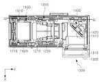
도 1은 일 실시 예에서 카메라 모듈(1000)의 사시도이다. 도 2는 일 실시 예에서 커버(1030)가 생략된 카메라 모듈(1000)의 사시도이다. 도 3은 일 실시 예에서 커버(1030)가 생략된 카메라 모듈(1000)의 상면도이다. 도 4는 일 실시 예에서 카메라 모듈(1000)의 분해사시도이다.1 is a perspective view of a
도 1을 참고하면, 카메라 모듈(1000)의 외관은 하우징(1010)의 일부 및 커버(1030)로 구성될 수 있다. 하우징(1010)과 커버(1030)에 의해 정의되는 공간에 폴디드 모듈(1100), 렌즈 모듈(1200), 또는 이미지 센서 모듈(1300) 등이 구비될 수 있다.Referring to FIG. 1 , the exterior of a
도 1을 참고하면, 커버(1030)는 상부에 수광용 개구부(1031)를 포함할 수 있다. 개구부(1031)를 통해 카메라 모듈(1000) 내부로 광이 진입할 수 있다. 도 2를 참고하면, 개구부(1031)로 들어온 광(L)은 폴디드 모듈(1100)의 제1반사부재(1110)로 입사하고, 제1반사부재(1110)는 상기 광(L)을 반사시킬 수 있다. 제1반사부재(1110)는 일방향으로 입사한 광의 방향을 렌즈 배럴(1210)을 향해 변환하도록 구성될 수 있다.Referring to FIG. 1 , the
도 2 및 도 4를 참고하면, 일 실시 예에서 카메라 모듈(1000)은 폴디드 모듈(1100), 렌즈 모듈(1200), 및 이미지 센서 모듈(1300)을 포함할 수 있다.Referring to FIGS. 2 and 4 , in one embodiment, a
일 실시 예에서 폴디드 모듈(1100)은 광(L)의 방향을 전환하도록 구성될 수 있다. 카메라 모듈(1000)을 상부에서 덮어주는 커버(1030)의 개구부(1031)를 통해 입사된 광(L)은 폴디드 모듈(1100)을 통해 렌즈 모듈(1200)로 전환 수 있다. 가령, 카메라 모듈(1000)의 두께 방향(Z축 방향)으로 입사된 광(L)은 폴디드 모듈(1100)에 의해 광축(Y축) 방향과 대략 일치하도록 전환될 수 있다. 폴디드 모듈(1100)에 관한 자세한 사항은 도 9 내지 도 11에서 설명된다.In one embodiment, the folded
일 실시 예에서 렌즈 모듈(1200)은 폴디드 모듈(1100)에서 반사된 광(L)을 굴절시킬 수 있다. 렌즈 모듈(1200)은 광축을 따라 배열된 복수의 렌즈들을 포함할 수 있고, 광(L)은 복수의 렌즈들을 통과하면서 굴절될 수 있다.In one embodiment, the
도 4를 참고하면, 일 실시 예에서 렌즈 모듈(1200)은 렌즈 배럴(1210), 및 렌즈 홀더(1220)를 포함할 수 있다. 렌즈 배럴(1210)은 내부에 복수의 렌즈들을 구비할 수 있다. 복수의 렌즈들은 원형 또는 가장자리가 커팅된 형태(이른바, 디컷(D-cut) 렌즈)를 가질 수 있다. 렌즈 배럴(1210)이 디컷 렌즈들을 구비한 경우, 렌즈 배럴(1210)의 외관도 디컷 렌즈에 대응하는 형태를 가질 수 있다.Referring to FIG. 4 , in one embodiment, the
일 실시 예에서 렌즈 배럴(1210)과 렌즈 홀더(1220)는 서로 별개의 구성일 수 있다. 예를 들어, 렌즈 배럴(1210)과 렌즈 홀더(1220)는 각각 제조된 이후에, 서로 결합될 수 있다.In one embodiment, the
일 실시 예에서 렌즈 모듈(1200)은 플레어(flare) 방지용 배플(baffle)(1250)을 더 포함할 수 있다. 배플(1250)은 내부에 입사공(1251)을 포함하는 액자형태를 가지고, 렌즈 홀더(1220)에 끼워질 수 있다.In an embodiment, the
일 실시 예에서 배플(1250)은 렌즈 배럴(1210)의 +Y방향에 배치될 수 있다. 배플(1250)은 렌즈 배럴(1210)을 통과한 광이 통과하도록 구성된 입사공(1250)을 포함한다.In one embodiment, the
렌즈 배럴(1210)을 통과한 광의 일부는 배플(1250)에 흡수되거나 배플(1250)에 의해 난반사될 수 있다. 이는 플레어가 생기는 것을 방지하거나 억제할 수 있다.Some of the light passing through the
일 실시 예에서 반사 모듈(1400)은 렌즈 모듈(1200)을 통과한 광을 이미지 센서(1310)를 향해 전환하도록 구성될 수 있다. 카메라 모듈(1000)은 반사 모듈(1400)을 구비함으로써, 광축 방향 길이(즉, Y축 방향 길이)를 크게 증가시키지 않고 비교적 큰 총 트랙길이(total track length, TTL)을 제공할 수 있다. 총 트랙길이는 렌즈 모듈(1200)에 구비된 복수의 렌즈들 중 물체 측에 가장 가까운 렌즈면과 이미지 센서의 센서면 사이의 최대 거리로서 정의된다. 총 트랙길이가 길수록 높은 줌 배율을 구현하는데 유리하고, 따라서 반사 모듈(1400)을 구비한 카메라 모듈(1000)은 비교적 높은 줌 배율을 제공할 수 있다.In an embodiment, the
일 실시 예에서 이미지 센서(1310)의 결상면은 렌즈 배럴(1210)의 광축방향과 교차하는 방향(예를 들어, X방향)을 향할 수 있다. 제2반사부재(1410)는 렌즈 배럴(1210)을 통과한 광을 이미지 센서(1310)의 결상면을 향해 변환하도록 구성될 수 있다.In an embodiment, an imaging plane of the
일 실시 예에서 반사 모듈(1400)은 제2반사부재(1410) 및 제2반사부재(1410)를 수용하는 홀더(1420)를 포함할 수 있다. 하우징(1010)은 홀더(1420)를 수용할 수 있는 지지구조(1020)를 포함할 수 있다. 예를 들어, 지지구조(1020)는 일방향으로 연장하는 그루브(1022)를 포함할 수 있고, 홀더(1420)는 그루브(1022)에 상응하는 구조를 포함할 수 있다.In one embodiment, the
본 발명의 실시 예들에 따른 카메라 모듈(1000)에서 폴디드 모듈(1100)과 반사 모듈(1400)에 의해 광 경로가 적어도 2차례 전환될 수 있다. 도 2를 참고하면, 폴디드 모듈(1100)에 Z축 방향으로 입사한 광(L)은 제1반사부재(1110)에 의해 Y축 방향으로 전환되고, 이 광(L)은 렌즈 모듈(1200)을 통과한 후 반사모듈(1400)의 제2반사부재(1410)에 의해 X축 방향으로 전환될 수 있다.In the
도시된 실시 예에서 반사 모듈(1400)을 통과한 광(L)이 꺾이는 방향은 +X 방향을 향하고, 이미지 센서가 반사 모듈(1400)의 +X 방향에 배치되나, 본 개시의 실시 예는 이에 한정되지 않으며, 다른 실시 예에서 반사 모듈(1400)이 광을 꺾는 방향은 다양할 수 있다. 도 3을 함께 참고하면, 반사 모듈(1400)을 통과한 광이 꺾이는 방향은 -X 방향을 향할 수 있고, 이 경우 이미지 센서 모듈(1300)은 반사 모듈(1400)을 기준으로 -X 방향에 구비될 수 있다.In the illustrated embodiment, the direction in which the light L passing through the
일 실시 예에서 이미지 센서 모듈(1300)은 이미지센서(1310) 및 이미지 센서(1310)가 실장되는 기판(1320)을 포함할 수 있다. 이미지 센서(1310)는 센서의 광 수집면(또는 결상면)이 반사 모듈(1400)의 제2반사부재(1410)를 향하도록 배치되며, 제2반사부재(1410)에서 반사된 광에 대응하는 이미지 신호를 생성할 수 있다.In one embodiment, the
일 실시 예에서 이미지 센서 모듈(1300)은 렌즈 모듈(1200)에서 입사되는 광을 필터링하는 광학필터를 포함할 수 있다. 광학필터는 적외선 차단 필터를 포함할 수 있다.In an embodiment, the
일 실시 예에서 하우징(1010)은 폴디드 모듈(1100), 렌즈 모듈(1200), 및 이미지 센서 모듈(1300)을 수용하도록 구성된 내부공간을 구비할 수 있다. 일 실시 예에서 이미지 센서 모듈(1300)의 일부는 하우징(1010) 외부에 구비될 수 있다. 예를 들어, 이미지 센서 모듈(1300)이 구비하는 기판(1320)은 하우징(1010)의 외부에 부착될 수 있다.In one embodiment, the
일 실시 예에서 하우징(1010)은 내부공간에 폴디드 모듈(1100), 렌즈 모듈(1200), 및 이미지 센서 모듈(1300)이 모두 수용되도록 일체로 구비될 수 있다. 다만, 이에 한정하는 것은 아니며, 다른 실시 예에서 하우징(1010)은 폴디드 모듈(1100), 렌즈 모듈(1200), 및 이미지 센서 모듈(1300) 중 일부를 수용하도록 구성된 하우징(1010)들이 상호 연결된 구조를 가질 수 있다.In one embodiment, the
도시된 실시 예에서 이미지 센서 모듈(1300)은 하우징(1010)에 구비되나, 다른 실시 예에서 이미지 센서 모듈(1300)을 수용하도록 구성된 별도의 하우징(1010)이 폴디드 모듈(1100)과 렌즈 모듈(1200)을 수용하는 하우징(1010)에 연결될 수 있다.In the illustrated embodiment, the
일 실시 예에서 플레어 방지용 배플(baffle)(1040)이 하우징(1010)에 구비될 수 있다. 배플(1040)은 내부에 관통부(1041)를 포함하는 액자형태를 가지고, 하우징(1010)의 내부 구조에 끼워질 수 있다. 배플(1040)은 하우징(1010)에 형성된 개구부(1011)와 대응하는 형태를 가질 수 있다. 제2반사부재(1410)에서 반사되어 이미지 센서(1310)로 향하는 광의 일부는 배플(1040)에 흡수되거나 배플(1040)에 의해 난반사될 수 있다. 이는 플레어가 생기는 것을 방지하거나 억제할 수 있다.In one embodiment, a
한편, 전자 장치에 채용되는 카메라가 다양한 기능(예를 들어, 손떨림방지, 자동초점)과 높은 성능을 제공함에 따라, 카메라 모듈(1000)의 두께는 줄어드는데 한계가 있다. 카메라 모듈(1000)의 두께에 의해 전자 장치의 두께가 결정될 수 있다.On the other hand, as cameras employed in electronic devices provide various functions (eg, anti-shake, auto focus) and high performance, there is a limit to reducing the thickness of the
도 12를 참고하면, 제1카메라 모듈(100)(도 1의 카메라 모듈(1000)에 대응함)이 제2카메라 모듈(200)과 함께 전자 장치(1)의 후면(A)에 구비될 수 있다. 제2카메라 모듈(200)의 두께가 커서 전자 장치(1)의 후면(A)에서 카메라로 인해 다른 부분보다 튀어나온 부분(A')이 존재할 수 있다. 이는 사용성과 외관의 심미성을 저해할 수 있기 때문에, 튀어나온 부분(A')의 면적을 줄이는 것이 중요하다.Referring to FIG. 12 , a first camera module 100 (corresponding to the
제1카메라 모듈(100)은 도 1의 카메라 모듈(1000)과 같이 단차부(S)를 포함할 수 있고, 이는 전자 장치(1)의 후면(A)에서 카메라로 인해 튀어나온 부분(A')의 면적을 줄이는데 기여할 수 있다.The
일 실시 예에서 카메라 모듈(1000)은 중간 부분에 두께가 저감되는 단차부(S)를 구비할 수 있다. 일 실시 예에서 단차부(S)는 카메라 모듈(1000)의 대략 중간 부분에 위치될 수 있다. 예를 들어, 단차부(S)는 카메라 모듈(1000)의 광축 방향 길이의 1/3 내지 2/3 지점에 구비될 수 있다. 일 실시 예에서 카메라 모듈(1000)은 렌즈모듈(1200)과 반사모듈(1400) 사이의 광 경로에 수직인 면을 경계로 단차질 수 있다. 예를 들어, 단차부(S)는 렌즈모듈(1200)의 피사체측 최전방 렌즈에서 반사모듈(1400)까지의 광경로 상에 위치될 수 있다.In one embodiment, the
도 1을 참고하면, 커버(1030)는 Y축 방향으로 단차진 부분(S1)을 포함하고, 해당 단차(S1)를 기준으로 카메라 모듈(1000)은 다른 높이(또는 두께)를 가질 수 있다. 일 실시 예에 따른 카메라 모듈(1000)에서 단차부(S)를 기준으로 수광용 개구부(1031)가 위치된 쪽의 높이는 반대쪽보다 높을 수 있다.Referring to FIG. 1 , the
도 4를 함께 참고하면, 일 실시 예에서 렌즈 모듈(1200)과 하우징(1010) 모두가 카메라 모듈(1000)의 외관에 드러난 단차부(S)에 대응하는 단차를 구비할 수 있다.Referring to FIG. 4 , in one embodiment, both the
일 실시 예에서 렌즈 모듈(1200)은 서로 구분되는 렌즈 배럴(1210)과 렌즈 홀더(1220)를 포함하고, 이들 각각은 적어도 하나의 단차(예를 들어, S2, S3, S4)를 포함할 수 있다. 예를 들어, 렌즈 홀더(1220)는 제2단차(S2)를 포함하고, 렌즈 배럴(1210)은 제3단차(S3) 및 제4단차(S4)를 포함할 수 있다.In one embodiment, the
일 실시 예에서 렌즈 홀더(1220)의 제2단차(S2)와 렌즈 배럴(1210)의 제3단차(S3)는 카메라 모듈(1000)의 외관에 드러난 단차부(S)에 대응하는 위치에 구비될 수 있다. 렌즈 배럴(1210)의 제4단차(S4)는 렌즈 배럴(1210)의 렌즈 홀더(1220)와의 조립의 편의를 위해 구비된 것일 수 있다.In one embodiment, the second step S2 of the
일 실시 예에서 하우징(1010)은 단차부(S)에 상응하는 제5단차(S5)를 포함할 수 있다. 예를 들어, 하우징(1010)을 구성하는 측벽(1010b)은 제5단차(S5)를 기점으로 다른 높이(Z축 방향 길이)를 가질 수 있다.In one embodiment, the
다시 도 12를 참고하면, 제1카메라 모듈(100)은 제2카메라 모듈(200)과 X축 방향으로 이격 배치된다. 제1카메라 모듈(100)은 제2카메라 모듈(1000)과 X축 방향으로 중첩되는 제1부분과 중첩되지 않는 제2부분을 포함할 수 있다. 그리고 제1카메라 모듈(100)은 제1부분과 제2부분 사이에 단차부(S)를 구비할 수 있다. 만약 제1부분과 제2부분의 두께가 같다면, 전자 장치의 후면에서 돌출되는 부분의 폭(Y축 방향 길이)은 도시된 부분(A')의 폭보다 클 것이다. 제1카메라 모듈(100)에서 제2부분의 두께는 제1부분의 두께보다 작기 때문에 카메라(100, 200)에 의해 돌출되는 부분(A')의 폭은 제1카메라 모듈의 폭보다 작아질 수 있다.Referring back to FIG. 12 , the
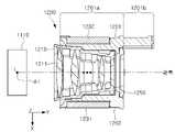
도 5는 도 2에서 렌즈 모듈(1200)의 I-I' 단면도이다. 도 6은 도 2에서 렌즈 모듈(1200)의 Ⅱ-Ⅱ' 단면도이다.FIG. 5 is a II' cross-sectional view of the
일 실시 예에서 렌즈 홀더(1220)는 렌즈 배럴(1210)을 수용하도록 구성될 수 있다. 일 실시 예에서 렌즈 홀더(1220)는 광축 방향(Y축 방향)으로 연장하는 제1지지구조물(1201)과 제2지지구조물(1202)을 포함할 수 있다. 제1지지구조물(1201)과 제2지지구조물(1202) 사이의 공간에 렌즈 배럴(1210)이 수용될 수 있다.In one embodiment, the
일 실시 예에서 제1지지구조물(1201)과 제2지지구조물(1202)은 광축을 기준으로 서로 반대방향에 배치될 수 있다. 제1지지구조물(1201)과 제2지지구조물(1202)은 사이에 광축을 두고 서로 대향할 수 있다. 예를 들어, 제1지지구조물(1201)과 제2지지구조물(1202)은 광축방향으로 연장하고 X방향으로 서로 대향하는 판형으로 각각 제공될 수 있다.In one embodiment, the
일 실시 예에서 렌즈 홀더(1220)의 내측구조는 렌즈 배럴(1210)의 외측구조에 대응하는 형상을 가질 수 있다. 예를 들어, 렌즈 배럴(1210)은 곡면을 포함하며, 지지구조물(1201, 1202)에서 렌즈 배럴(1210)을 마주보는 부분도 렌즈 배럴(1210)의 곡면에 대응하는 곡면을 포함할 수 있다. 예를 들어, 렌즈 배럴(1210)은 광축 방향으로 단차진 부분을 포함할 수 있고, 지지구조물(1201, 1202)의 내측구조도 렌즈 배럴(1210)의 단차에 대응하는 단차를 포함할 수 있다.In an embodiment, the inner structure of the
일 실시 예에서 제1지지구조물(1201)은 제2지지구조물(1202)에 비해 광축 방향의 길이가 더 길다. 예를 들어, 제1지지구조물(1201)은 제2지지구조물(1202)과 X방향으로 대향하는 제1부분(1201a), 및 제1부분(1201a)의 단부에서 +Y방향으로 더 연장된 제2부분(또는 연장부)(1201b)을 포함할 수 있다. 제1지지구조물(1201)의 제1부분(1201a)은 제2지지구조물(1202)과 동일 또는 대체로 동일한 광축방향 길이를 가지며, 제1지지구조물(1201)의 제2부분(1201b)으로 인해 제1지지구조물(1201)은 제2지지구조물(1202)보다 +Y방향으로 더 돌출된다. 제2부분(1201b)으로 인해 제1지지구조물(1201)은 렌즈 배럴(1210)의 후방(+Y방향)으로 제2지지구조물(1202)보다 더 돌출될 수 있다.In one embodiment, the length of the
일 실시 예에서 제2지지구조물(1202)은 반사모듈(1400)에서 이미지 센서(1310)로 향하는 광과 간섭되지 않게 마련될 수 있다.In one embodiment, the
일 실시 예에서 렌즈 홀더(1220)는 제1지지구조물(1201)과 제2지지구조물(1202)을 연결하는 구조를 포함할 수 있다. 일 실시 예에서 렌즈 홀더(1220)는 제1지지구조물(1201)의 상부와 제2지지구조물(1202)의 상부를 연결하는 상부구조물(1203)을 포함할 수 있다. 일 실시 예에서 렌즈 홀더(1220)는 제1지지구조물(1201)의 하부와 제2지지구조물(1202)의 하부를 연결하는 하부구조물(1204)을 포함할 수 있다.In one embodiment, the
렌즈 홀더(1220)의 상부구조물(1203)과 하부구조물(1204)은 각각 렌즈 배럴(1210)의 위(+Z 방향)와 아래(-Z 방향)에 배치될 수 있다. 렌즈 배럴(1210)은 후방(+Y방향)으로 갈수록 두께(Z축 방향 길이)가 얇아지고, 얇아진 두께로 인해 렌즈 배럴(1210)의 상하에 확보된 공간(1212)에 렌즈 홀더(1220)의 상부구조물(1203) 및 하부구조물(1204)이 배치될 수 있다.The
예를 들어, 렌즈 배럴(1210)은 X축 방향으로 바라볼 때, 제3단차(S3) 또는 제4단차(S4)를 경계로 후방부분의 두께가 전방 부분의 두께보다 얇다. 렌즈 배럴(1210)에서 얇아진 두께에 의해 렌즈 배럴(1210)의 상하부에 확보된 공간(1212)에 상부구조물(1203)과 하부구조물(1204)의 일부가 배치될 수 있다. 이에 따라, 렌즈 배럴(1210)과 렌즈 홀더(1220)가 별개 구성으로 마련되는 것으로 인한 렌즈 모듈(1200)의 두께 증가가 최소화될 수 있다.For example, when the
일 실시 예에서 렌즈 홀더(1220)에 자동초점조절에 필요한 구동요소들이 구비될 수 있다. 일 실시 예에서 제1마그넷(1231)은 제1지지구조물(1201)에 구비될 수 있다. 일 실시 예에서 제2지지구조물(1202)에 제2마그넷(1232)이 구비될 수 있다. 도 7을 함께 참고하면, 일 실시 예에서 하부구조물(1204)에 제1자성부재(1233)가 구비될 수 있다. 제1자성부재(1233)는 하부구조물(1204)에서 하우징(1010) 바닥면(1010a)을 마주보는 부분에 배치될 수 있다.In one embodiment, the
도 7을 함께 참고하면, 지지구조물(1201, 1202)의 바닥면에 가이드홈들(1221, 1222, 1223)이 배치될 수 있다. 제1지지구조물(1201)은 바닥면에 제2가이드홈(1222) 및 제3가이드홈(1223)을 포함할 수 있다. 제2지지구조물(1202)은 바닥면에 제1가이드홈(1221)을 포함할 수 있다.Referring to FIG. 7 together, guide
일 실시 예에서 연장부(1201b)에 제3가이드홈(1223)의 적어도 일부가 구비되며, 제3볼부재(1243)가 제3가이드홈(1223)을 따라 미끄러지거나 구를 수 있다. 제3볼부재(1243)는 연장부(1201b)를 지지할 수 있고, 렌즈 모듈(1200)을 지지하는 여러 지지점들 중 하나를 담당할 수 있다.In one embodiment, at least a part of the
한편, 카메라 모듈(1000)이 높은 줌 배율을 제공하기 위해 렌즈 배럴(1210)은 비교적 긴 스트로크(stroke)를 가질 수 있다. 긴 스트로크를 가지는 렌즈 배럴(1210)을 안정적으로 지지하기 위해서는 렌즈 배럴(1210)을 지지하는 지지점들 사이의 간격이 커야한다. 예를 들어, 렌즈 배럴(1210)은 렌즈 배럴(1210)과 하우징(1010) 사이에 배치된 볼부재들(1241, 1242, 1243)에 의해 지지될 수 있는데, 볼부재들(1241, 1242, 1243) 사이의 간격이 커야 렌즈 모듈(1200)이 흔들리지 않고 안정적으로 이동할 수 있다. 볼부재들(1241, 1242, 1243)에 의한 렌즈 모듈(1200)의 지지에 관한 내용은 도 8에서 상세히 설명된다.Meanwhile, in order for the
일 실시 예에서 볼부재들(1241, 1242, 1243) 사이의 거리를 늘리기 위해 렌즈 모듈(1200)은 비대칭적으로 형성될 수 있다. Z축 방향에서 바라볼 때 렌즈 모듈(1200)은 광축을 기준으로 비대칭적인 구조를 가질 수 있다. 도 7을 참고하면, 제2볼부재(1242)와 제3볼부재(1243) 사이의 거리를 늘리기 위해서 제1지지구조물(1201)은 제2지지구조물(1202)보다 렌즈 배럴(1210)의 후방으로 더 돌출된 연장부(1201b)를 포함할 수 있다.In one embodiment, the
제1지지구조물(1201)의 길이가 클수록 제2볼부재(1242)와 제3볼부재(1243) 사이의 거리가 커질 수 있고, 볼부재들(1241, 1242, 1243)에 의해 둘러싸인 영역의 면적(예를 들어, 도 8의 지지영역(T))이 더 넓어질 수 있다. 이는 렌즈 모듈(1200)이 비교적 긴 스트로크로 이동하는데 기여할 수 있다.As the length of the
한편, 렌즈 모듈(1200)이 비대칭적으로 형성되는 경우, 렌즈 배럴(1210)과 렌즈 홀더(1220)가 별개의 구성으로 마련되는 것이 더 유리하다. 렌즈 모듈(1200)이 제조되는 환경 또는 사용되는 환경에 따라 렌즈 모듈(1200)을 구성하는 구조물들이 변형될 수 있는데, 렌즈 모듈(1200)이 비대칭으로 형성될수록 변형 정도가 클 수 있다. 렌즈 모듈(1200)이 구비하는 렌즈들(1211)은 정확하게 광축을 따라 배열되는 것이 중요한데, 위와 같은 변형으로 인해 렌즈들(1211)의 배열이 어긋날 수 있고 이는 이미지 품질의 저하를 초래할 수 있다.Meanwhile, when the
일 실시 예에서 렌즈 배럴(1210)은 광축을 기준으로 대칭적인 구조를 가지며, 렌즈 배럴(1210)과 별개로 마련되는 렌즈 홀더(1220)가 광축을 기준으로 비대칭적인 구조를 가질 수 있다.In an embodiment, the
일 실시 예에서 렌즈 배럴(1210)은 광축을 포함하고 제1지지구조물(1201)과 제2지지구조물(1202)이 대향하는 방향(즉, X축 방향)에 수직인 면을 기준으로 대칭적으로 구성될 수 있다. 예를 들어, 도 5를 참고하면, 렌즈 배럴(1210)은 YZ 평면과 평행하고 광축을 포함하는 평면을 기준으로 대칭적인 형상을 가질 수 있다. 일 실시 예에서 렌즈 배럴(1210)은 광축을 포함하고 제1지지구조물(1201)과 제2지지구조물(1202)이 대향하는 방향에 나란한 면을 기준으로 대칭적으로 구성될 수 있다. 예를 들어, 도 6을 참고하면, 렌즈 배럴(1210)은 XY 평면과 평행하고 광축을 포함하는 평면을 기준으로 대칭적인 형상을 가질 수 있다.In one embodiment, the
도 5를 참고하면, 제1방향(예를 들어, -Z방향)으로 제1반사부재(1110)에 입사한 광(L)은 광축을 향해 반사된다. 일 실시 예에서 렌즈 배럴(1210)은 광축을 포함하고, 제1방향과 나란한 제1면을 기준으로 대칭적인 형태로 제공될 수 있다. 예를 들어, 렌즈 배럴(1210)은 YZ 평면과 평행하고 광축을 포함하는 평면을 기준으로 대칭적인 형상을 가질 수 있다. 도 5를 참고하면, 광축을 기준으로 -X방향에 배치된 제1지지구조물(1201)은 +X방향에 배치된 제2지지구조물(1202)과 다른 구조를 가지며, 따라서 렌즈 홀더는 렌즈 배럴(1210)과 달리 상기 제1면을 기준으로 비대칭적인 형태로 제공된다.Referring to FIG. 5 , light L incident on the first
도 6을 참고하면, 일 실시 예에서 렌즈 배럴(1210)은 광축을 포함하고, 제1방향과 수직인 면을 기준으로 대칭적인 형태를 가지도록 제공될 수 있다. 일 실시 예에서 렌즈 배럴(1210)은 광축을 포함하고 제1반사부재(1110)의 반사면(1110a)과 수직인 평면을 기준으로 대칭적인 형태를 가지도록 제공될 수 있다. 예를 들어, 도 6을 참고하면, 렌즈 배럴(1210)은 XY 평면과 평행하고 광축을 포함하는 평면을 기준으로 대칭적인 형상을 가질 수 있다.Referring to FIG. 6 , in one embodiment, the
일 실시 예에서 렌즈 모듈(1200)이 긴 스크로크를 가지기 위해 비대칭적인 구조를 가지더라도, 렌즈 배럴(1210)은 대칭적인 구조를 가지므로 렌즈들(1211)의 정렬이 어긋나는 것이 방지되거나 최소화될 수 있다.In one embodiment, even though the
도 7은 일 실시 예에서 렌즈 모듈(1200)의 구동부의 분해사시도이다. 도 8은 일 실시 예에서 카메라 모듈(1000)을 위에서 봤을 때, 렌즈 모듈(1200)의 지지점들과 제1자성부재(1233)의 위치관계를 도시한 것이다. 도 8은 도 3의 I-I' 단면도이다. 도 8은 렌즈 모듈(1200)에 구비된 제1자성부재(1233)와 하우징(1010)에 구비된 제2자성부재(1260)가 나타나도록 카메라 모듈(1000)을 절단한 단면이다.7 is an exploded perspective view of a driving unit of the
일 실시 예에서 렌즈 모듈(1200)은 하우징(1010)에 이동 가능하게 구비될 수 있다. 일 실시 예에서 렌즈 모듈(1200)이 하우징(1010)에 대해 일방향으로 왕복운동하면서 이미지 센서(1310)에 맺히는 상의 초점 또는 배율이 조절될 수 있다. 일 실시 예에서 렌즈 모듈(1200)은 하우징(1010)에 대해 광축(Y축)과 나란한 방향으로 이동할 수 있다.In one embodiment, the
일 실시 예에서 렌즈 모듈(1200)의 이동을 가이드하기 위해 볼부재들(1241, 1242, 1243)과 가이드홈들(1221, 1222, 1223, 1014, 1015, 1016)이 이용될 수 있다. 렌즈 모듈(1200)과 하우징(1010)은 각각 서로 마주보는 부분에 제1방향(Y축 방향)으로 연장하는 가이드홈들(1221, 1222, 1223, 1014, 1015, 1016)을 포함할 수 있다. 볼부재들(1241, 1242, 1243)이 렌즈 모듈(1200)과 하우징(1010)에 구비된 가이드홈들(1221, 1222, 1223, 1014, 1015, 1016) 사이에 배치될 수 있다.In one embodiment,
일 실시 예에서 볼부재들(1241, 1242, 1243)은 가이드홈들(1221, 1222, 1223, 1014, 1015, 1016)이 연장된 방향을 따라서만 이동하므로, 렌즈 모듈(1200)의 운동방향은 하우징(1010)에 대해 가이드홈들(1221, 1222, 1223, 1014, 1015, 1016)의 길이방향(Y축 방향)으로 제한될 수 있다.In one embodiment, since the
일 실시 예에서 렌즈 홀더(1220)는 하면(1220b)에 제1가이드홈(1221), 제2가이드홈(1222), 제3가이드홈(1223)을 포함할 수 있다. 하우징(1010)은 바닥면(1010a)에 제1가이드홈(1221), 제2가이드홈(1222), 및 제3가이드홈(1223)에 각각 대응하는 제4가이드홈(1014), 제5가이드홈(1015), 및 제6가이드홈(1016)을 포함할 수 있다. 제1가이드홈(1221)과 제4가이드홈(1014) 사이에 제1볼부재(1241)가 배치되고, 제2가이드홈(1222)과 제5가이드홈(1015) 사이에 제2볼부재(1242)가 배치되고, 제3가이드홈(1223)과 제6가이드홈(1016) 사이에 제3볼부재(1243)가 배치될 수 있다.In one embodiment, the
일 실시 예에서 카메라 모듈(1000)은 렌즈 모듈(1200)에 구동력을 제공하는 구동부를 포함할 수 있다. 일 실시 예에서 구동부는 렌즈 모듈(1200)에 구비된 마그넷(1231, 1232)과 하우징(1010)에 구비된 코일(1251, 1252)을 포함할 수 있다.In one embodiment, the
일 실시 예에서 렌즈 홀더(1220)의 측면(1220a)에 제1마그넷(1231)과 제2마그넷(1232)이 구비될 수 있다. 하우징(1010)에는 제1마그넷(1231) 및 제2마그넷(1232)에 각각 대응하는 제1코일(1251)과 제2코일(1252)이 구비될 수 있다. 코일(1251, 1252)과 마그넷(1231, 1232)의 전자기적 상호작용을 통해 렌즈 모듈(1200)이 하우징(1010)에 대해 일방향으로 왕복운동할 수 있다. 예를 들어, 코일(1251, 1252)과 마그넷(1231, 1232)에 생기는 로렌츠힘이 렌즈 모듈(1200)을 하우징(1010)에 대해 일방향으로 움직이게 할 수 있다.In one embodiment, the
일 실시 예에서 제1코일(1251)과 제2코일(1252)은 하우징(1010)의 외벽에 배치되는 기판(1050)에 부착될 수 있다. 기판(1050)에 부착된 제1코일(1251) 및 제2코일(1252)은 하우징(1010)에 구비된 개구부(1012, 1013)를 통해서 각각 제1마그넷(1231) 및 제2마그넷(1232)과 상호작용할 수 있다. 하우징(1010)에 구비된 개구(1012, 1013)는 제1코일(1251)과 제2코일(1252)에 대응하는 크기로 제공될 수 있다.In one embodiment, the
일 실시 예에서 렌즈 홀더(1220)는 하우징(1010)에 대해 밀착된 상태로 이동해야 한다. 다시말해, 렌즈 홀더(1220)가 하우징(1010)에 대해 움직이는 동안 볼부재들(1241, 1242, 1243)은 양측에 구비된 가이드홈들(1221, 1222, 1223, 1014, 1015, 1016)과의 접촉을 유지해야 한다. 도 7을 참고하면, 제1볼부재(1241)는 제1가이드홈(1221) 및 제4가이드홈(1014)과 접촉을 유지해야하고, 제2볼부재(1242)는 제2가이드홈(1222) 및 제5가이드홈(1015)과 접촉을 유지해야하고, 제3볼부재(1243)는 제3가이드홈(1223) 및 제6가이드홈(1016)과 접촉을 유지해야한다. 만약 제1볼부재(1241), 제2볼부재(1242), 또는 제3볼부재(1243) 중 어느 하나라도 가이드홈(1221, 1222, 1223, 1014, 1015, 1016)으로부터 접촉이 해제되면, 렌즈 홀더(1220)의 운동방향은 더 이상 일방향으로 제한되지 못한다. 예를 들어, 렌즈 홀더(1220)는 Y축방향으로만 이동해야 하는데 볼부재(1241, 1242, 1243)와 가이드홈(1221, 1222, 1223, 1014, 1015, 1016)의 접촉이 해제되면, 렌즈 홀더(1220)가 Z축 또는 X축 방향으로도 흔들릴 수 있다. 이는 자동초점 조절기능 및 이미지 품질의 저하를 초래할 수 있다.In one embodiment, the
이에 따라 하우징(1010)과 렌즈 홀더(1220)는 각각 서로를 잡아당길 수 있는 요소를 포함할 수 있다. 일 실시 예에서 렌즈 홀더(1220)와 하우징(1010)은 각각 서로 마주보는 부분에 적어도 하나의 자성부재(1233, 1260)를 구비할 수 있다.Accordingly, the
렌즈 홀더(1220)와 하우징(1010)에 구비된 자성부재들(1233, 1260)의 조합은 이들 사이에 자기적 인력이 생기도록 구성될 수 있다. 예를 들어, 하우징(1010)에 구비된 자성부재(1260)는 마그넷이고 렌즈 홀더(1220)에 구비된 제1자성부재(1233)는 마그넷 또는 요크일 수 있다. 다른 예를 들어, 하우징(1010)에 구비된 자성부재(1260)는 요크이고 렌즈 홀더(1220)에 구비된 제1자성부재(1233)는 마그넷일 수 있다.A combination of the
도 7을 참고하면, 제1자성부재(1233)가 렌즈 홀더(1220)의 하면(1220b)에 구비되고, 제2자성부재(1260)가 하우징(1010)의 바닥면(1010a)에 구비될 수 있다. 렌즈 홀더(1220)는 제1자성부재(1233)를 수용하기위한 함몰부를 포함할 수 있다.Referring to FIG. 7 , the first
도 8을 참고하면, 제2자성부재(1260)는 하우징(1010) 바깥에 구비되고, 하우징(1010)은 제2자성부재(1260)의 일부를 하우징(1010) 내부로 노출시키는 개구부(1070)를 제공할 수 있다. 렌즈 모듈(1200)의 구동에 따라 제1자성부재(1233)와 제2자성부재(1260) 사이에 하우징(1010)의 일부가 배치될 수 있지만, 제1자성부재(1233)와 제2자성부재(1260) 사이의 자기적 인력은 여전히 생길 수 있다.Referring to FIG. 8 , the second
자성부재들(1233, 1260)로 인해 렌즈 홀더(1220)에는 렌즈 홀더(1220)를 하우징(1010)의 바닥면(1010a)으로 잡아당기는 힘이 지속적으로 작용할 수 있고, 이에 따라 렌즈 홀더(1220)는 하우징(1010)의 바닥면(1010a)에 밀착된 상태로 이동할 수 있다. 즉, 자성부재들(1233, 1260)에 의한 자기적 인력이, 볼부재들(1241, 1242, 1243)이 양측에 구비된 가이드홈들(1221, 1222, 1223, 1014, 1015, 1016)과 접촉을 유지할 수 있게 도와준다.Due to the
일 실시 예에서 렌즈 홀더(1220)는 비대칭적으로 형성될 수 있다. 도 4와 도 7을 참고하면, 일 실시 예에서 렌즈 홀더(1220)는 광축 방향으로 연장하는 연장부(1201b)를 포함할 수 있다. 렌즈 홀더(1220)는 광축을 기준으로 렌즈 배럴(1210)을 양측에서 감싸는 두개의 지지구조물들(또는 측벽들)(1201, 1202)을 포함할 수 있다. 일측 지지구조물(1201)의 광축 방향 길이는 타측 지지구조물(1202)의 광축 방향 길이보다 길게 형성될 수 있다. 이때, 일측 지지구조물(1201)에서 타측 지지구조물(1202)의 길이보다 광축 방향으로 더 길게 연장된 부분이 연장부(1201b)로 정의될 수 있다.In one embodiment, the
일 실시 예에서 렌즈 홀더(1220)는 적어도 3개 이상의 지지점을 가지면서 하우징(1010)의 바닥면(1010a)에 밀착될 수 있다. 일 실시 예에서 렌즈 홀더(1220)의 연장부(1201b)에 적어도 하나의 지지점이 존재할 수 있다. 예를 들어, 제3가이드홈(1223)의 적어도 일부는 연장부(1201b)에 구비되고, 제3가이드홈(1223)에 일부 수용된 제3볼부재(1243)가 하나의 지지점을 제공할 수 있다.In one embodiment, the
일 실시 예에서 렌즈 홀더(1220)는 하우징(1010)의 바닥면(1010a)과 사이에 배치된 제1볼부재(1241), 제2볼부재(1242), 및 제3볼부재(1243)에 의해 적어도 일부 지지되고, 상기 제1볼부재(1241)는 제2지지구조물(1202)과 바닥면(1010a) 사이에 배치되고, 제2볼부재(1242)는 제1지지구조물(1201) 중 제2지지구조물(1202)과 대응하는 부분(예를 들어, 도 5의 제1부분(1201a))과 바닥면(1010a) 사이에 배치되고, 제3볼부재(1243)는 제1지지구조물(1201)의 연장부(1201b)와 바닥면(1010a) 사이에 배치될 수 있다.In one embodiment, the
여기서 하나의 지지점은 물리적으로 하나의 점을 의미하는 것은 아니며, 서로 가까이 배치된 2개 이상의 접촉점들로 구성될 수 있다. 예를 들어, 제3가이드홈(1223)이 V형 단면을 가지는 경우에 제3볼부재(1243)는 제3가이드홈(1223)과 2개의 접촉점을 가질 수 있고, 이들 2개의 접촉점들이 단일 지지점을 구성할 수 있다. 다른 예를 들어, 제3가이드홈(1223)이 넓은 바닥면을 가지는 경우에 제3볼부재(1243)는 제3가이드홈(1223)의 바닥면과 1개의 접촉점을 가질 수 있고, 1개의 접촉점이 단일 지지점을 구성할 수 있다.Here, one support point does not mean physically one point, and may consist of two or more contact points disposed close to each other. For example, when the
도 8을 참고하면, 제2자성부재(1260)는 제1자성부재(1233)의 이동구간을 모두 커버(1030)하도록 구성될 수 있다. 예를 들어, 제2자성부재(1260)의 Y축 방향 길이는 제1자성부재(1233)의 이동구간에 대응할 수 있다. 렌즈 모듈(1200)의 구동에 따라 제1자성부재(1233)가 움직이더라도 제1자성부재(1233)는 항상 제2자성부재(1260) 상에 배치되고, 제1자성부재(1233)와 제2자성부재(1260) 사이에 항상 자기적 인력이 생길 수 있다.Referring to FIG. 8 , the second
도 8을 참고하면, 제1자성부재(1233)는 볼부재들(1241, 1242, 1243)에 의해 정의되는 삼각형 영역(T) 내에 위치될 수 있다. 일 실시 예에서 제2자성부재(1260) 역시 볼부재들(1241, 1242, 1243)에 의해 정의되는 삼각형 영역(T) 내에 위치될 수 있다.Referring to FIG. 8 , the first
도 6 및 도 7을 참고하면, 일 실시 예에서 렌즈 홀더(1220)는 제1지지구조물(1201)과 제2지지구조물(1202) 사이를 연결하고, 바닥면(1010a)에 대향하는 하부구조물(1204)을 더 포함하고, 제1자성부재(1333)는 하부구조물(1204)에 구비될 수 있다. 일 실시 예에서 렌즈 배럴(1210)은 바닥면(1010a)과 대향하는 제1면(1210a), 및 바닥면(1010a)과 대향하되 제1면(1210a)보다 상기 바닥면(1010a)으로부터 +Z방향으로 더 이격된 제2면(1210b)을 포함한다. 제2면(1210b)과 제1면(1210a) 사이에 제3단차(S3)가 제공된다. 이때 하부구조물(1204)은 제2면(1210b)과 바닥면(1010a) 사이에 배치될 수 있다.6 and 7, in one embodiment, the
한편, 제1자성부재(1233)는 볼부재들(1241, 1242, 1243)에 의해 정의되는 지지영역(T) 내부에 위치되는 것이 렌즈 모듈(1200)의 안정적인 구동에 유리하다. 예를 들어, 제2볼부재(1242)와 제3볼부재(1243)사이의 거리가 도시된 실시 예보다 좁은 경우를 상정하면, 제1자성부재(1233)가 Y축 방향으로 움직일 때 제1자성부재(1233)가 지지영역(T)의 가장자리 또는 지지영역(T)에서 벗어난 위치에 배치될 수 있다. 이 경우 제1자성부재(1233)와 제2자성부재(1260)사이의 자기적 인력에 의해 렌즈 모듈(1200)이 기울어지고, 볼부재들(1241, 1242, 1243)의 가이드홈들(1221, 1222, 1223, 1014, 1015, 1016)에 대한 접촉이 해제될 수 있다. 특히, 높은 줌 배율을 제공하는 카메라 모듈(1000)에서 렌즈 모듈(1200)의 구동길이는 비교적 크기 때문에, 지지영역(T)이 좁다면 위와 같은 문제점이 생길 가능성이 더 높을 수 있다.Meanwhile, it is advantageous for stable driving of the
일 실시 예에서 렌즈 모듈(1200)은 연장부(1201b)를 포함하고 연장부(1201b)의 일부가 제3가이드홈(1223)을 정의할 수 있다. 제3볼부재(1243)가 연장부(1201b)에 구비된 제3가이드홈(1223)에 구비됨에 따라 제2볼부재(1242)와 제3볼부재(1243) 사이의 거리가 비교적 큰 값을 가지도록 설계될 수 있다. 제2볼부재(1242)와 제3볼부재(1243)의 간격이 커지면, 볼부재들(1241, 1242, 1243)에 의해 정의되는 지지영역(T)의 면적이 커지고, 이는 제1자성부재(1233)가 움직일 수 있는 범위가 커질 수 있음을 의미할 수 있다.In one embodiment, the
이에 따라 비교적 긴 구동길이를 가지는 렌즈 모듈(1200)도 하우징(1010)에 안정적으로 지지될 수 있다. 또, 높은 줌 배율을 제공하기 위해 렌즈 모듈(1200)의 구동거리가 커지더라도 본 개시의 실시 예들에 따르면 렌즈 모듈(1200)이 안정적으로 구동할 수 있다.Accordingly, even the
일 실시 예에서 제1자성부재(1233)는 렌즈 홀더(1220)의 하면에 구비되되, 제2지지구조물(1202)보다 제1지지구조물(1201)에 가까이 배치될 수 있다. 예를 들어, 제1자성부재(1233)는 제1가이드홈(1014)보다 제2가이드홈(1015)(또는 제3가이드홈(1016))에 가까이 배치될 수 있다. 렌즈 홀더(1220)는 3개의 볼부재들(1241, 1242, 1243)에 의해 지지될 수 있고, 3개의 볼부재들(1241, 1242, 1243) 중 2개의 볼부재들(1242, 1243)이 제1지지구조물에 구비된 가이드홈들(1015, 1016))에 배치될 수 있다.In one embodiment, the first
제1자성부재(1233)가 제1지지구조물(1201)에 더 가까이 배치되는 것이 렌즈 홀더(1220)가 안정적으로 지지되는데 유리하다. 도 8을 참고할 때, 제1자성부재(1233)는 광축(Y축)을 따라 이동하고, 제2볼부재(1242)와 제3볼부재(1243)에 의해 정의되는 변에 가까이 위치되면, 제1자성부재(1233)가 볼부재들(1241, 1242, 1243)에 의해 정의되는 지지영역(T) 내부에서 이동할 수 있는 범위가 넓어지기 때문이다.Disposing the first
한편, 렌즈 모듈(1200)이 하우징(1010)에 대해 이동함에 따라 볼부재들(1241, 1242, 1243)도 같은 방향으로 구를 수 있고, 이는 지지영역(T)도 하우징(1010)을 따라 이동함을 의미한다. 다만, 볼부재들(1241, 1242, 1243)이 구른 거리가 렌즈 모듈(1200)의 이동거리와 일치할 뿐, 불부재들(1241, 1242, 1243)의 중심들이 이동한 거리는 렌즈 모듈(1200)의 이동거리에 못 미치기 때문에 여전히 볼부재들(1241, 1242, 1243)이 넓은 면적의 지지영역(T)을 제공하는 것이 중요하다. 따라서 연장부(1201b) 및 연장부(1201b)에 구비된 볼부재(1243)가 렌즈 모듈(1200)을 안정적으로 지지하는데 기여한다는 것은 변함없다.Meanwhile, as the
본 개시의 실시 예들은 지지점들 중 하나가 연장부(1201b)에 배치된다는 것을 특징으로 가질 뿐, 지지점이 반드시 볼부재-가이드홈의 조합(예를 들어, 제1볼부재(1241), 제1가이드홈(1221), 및 제4가이드홈(1014))으로 제공될 필요는 없다. 예를 들어, 연장부(1201b)는 하우징(1010)의 바닥면(1010a)으로 돌출된 부분을 포함할 수 있고, 렌즈 모듈(1200)의 지지점들 중 하나는 상기 돌출부에 의해 제공될 수 있다. 다른 예를 들어, 하우징(1010)의 바닥면(1010a)에서 연장부(1201b)를 향해 연장된 돌출부가 렌즈 모듈(1200)에 지지점을 제공할 수 있다.Embodiments of the present disclosure are characterized in that one of the support points is disposed on the
일 실시 예에서 3개의 볼부재들(1241, 1242, 1243) 외에도 다른 구조가 렌즈 모듈(1200)의 일부 지지할 수 있다. 일 실시 예에서 렌즈 홀더(1220)는 지지구조물(1202)의 하면(1220b)에 하우징(1010)의 바닥면(1010a)으로 돌출된 돌기(1280)를 포함할 수 있다. 돌기(1280)는 렌즈 모듈(1200)을 보조적으로 지지하는 역할을 할 수 있다. 렌즈 모듈(1200)이 하우징(1010)에 조립되었을 때, 돌기(1280)의 단부와 하우징(1010)의 바닥면(1010a) 사이에 에어갭(air gap)이 존재할 수 있다. 렌즈 모듈(1200)에 강한 충격이 가해졌을 때, 돌기(1280)는 볼부재들(1241, 1242, 1243)과 함께 렌즈 모듈(1200)을 지지할 수 있다. 다른 실시 예에서 돌기(1280)는, 볼부재 및 하우징(1010)과 렌즈 홀더(1220)에 각각 구비된 가이드홈들로 대체될 수 있다.In one embodiment, other structures in addition to the three
도 9는 일 실시 예에서 카메라 모듈(1000)에 구비되는 스타퍼들(stoppers)을 도시한다. 도 10은 도 3의 Ⅲ-Ⅲ' 단면도이다. 도 10은 스타퍼가 나타나도록 카메라 모듈(1000)을 절단한 단면이다.9 shows stoppers provided in the
폴디드 모듈(1100)이나 렌즈 모듈(1200)이 하우징(1010) 내에서 움직일 있는 범위는 제한적이다. 폴디드 모듈(1100) 또는 렌즈 모듈(1200)의 운동범위는 하우징(1010) 내부 구조에 의해 제한될 수 있다.A range in which the folded
도 9를 참고하면, 하우징(1010)은 내측으로 돌출된 걸림턱(1081, 1082, 1083)을 포함할 수 있다. 렌즈 모듈(1200)이 광축 방향(Y축 방향)으로 이동할 때 걸림턱(1081, 1082, 1083)에 닿을 수 있고, 이는 렌즈 모듈(1200)의 이동범위의 상한과 하한을 결정할 수 있다. 도시된 실시 예에서 렌즈 모듈(1200)의 일측에 제1걸림턱(1081), 제2걸림턱(1082)이 구비되고, 타측에 제3걸림턱(1083)이 배치될 수 있다. 일 실시 예에서 제1걸림턱(1081)과 제2걸림턱(1082)은 폴디드 모듈(1100)의 회전범위를 결정하는 역할도 할 수 있다.Referring to FIG. 9 , the
그런데 렌즈 모듈(1200)이나 폴디드 모듈(1100)이 그 운동범위의 상한 또는 하한에 있을 때, 하우징(1010) 내부 구조에 닿으면서 소음이 생길 수 있다. 충격량이 크거나, 반복적인 충돌로 인해 하우징(1010) 내부 구조, 렌즈 모듈(1200), 또는 폴디드 모듈(1100)이 손상될 수도 있다.However, when the
일 실시 예에서 카메라 모듈(1000)은 하우징(1010)과 렌즈 모듈(1200)(또는 폴디드 모듈(1100)) 사이에 소음과 충격량을 줄이기 위한 스타퍼(1500)를 포함할 수 있다.In one embodiment, the
일 실시 예에서 렌즈 모듈(1200)(또는 폴디드 모듈(1100))과 하우징(1010) 사이에 스타퍼(1500)가 배치될 수 있다. 렌즈 모듈(1200)(또는 폴디드 모듈(1100))이 일측으로 최대한 이동하더라도 렌즈 모듈(1200)(또는 폴디드 모듈(1100))의 단부가 하우징(1010)에 직접 부딪치지 않고, 스타퍼(1500)에 부딪친다. 스타퍼(1500)는 완충작용을 할 수 있도록 탄성이 있는 소재를 포함할 수 있다.In one embodiment, the
도 10을 참고하면, 일 실시 예에서 스타퍼는 완충부재(예를 들어, 1521, 1531)와 완충부재를 하우징(1010)에 고정시키는 체결부재(예를 들어, 1522, 1532)를 포함할 수 있다. 체결부재는 하우징(1010) 내부 구조에 결합될 수 있다. 예를 들어, 완충부재는 고무, 실리콘 등으로 이루어질 수 있다.Referring to FIG. 10 , in one embodiment, the stopper may include buffer members (eg, 1521 and 1531) and fastening members (eg, 1522 and 1532) for fixing the buffer member to the
도 9 및 도 10을 참고하면, 일 실시 예에서 제1걸림턱(1081), 제2걸림턱(1082), 및 제3걸림턱(1083)에 제1스타퍼(1510), 제2스타퍼(1520) 및 제3스타퍼(1530)가 각각 구비될 수 있다. 일 실시 예에서 렌즈 모듈(1200)의 단부(1220c, 1220d)는 걸림턱(1081, 1082, 1083)에 직접 부딪치지 않고 스타퍼(1500)에 부딪치며, 이는 렌즈 모듈(1200)이 걸림턱(1081, 1082, 1083)에 부딪치면서 생길 수 있는 소음이나 파손 등의 문제를 억제/방지할 수 있다.9 and 10, in an embodiment, a
일 실시 예에서 제3스타퍼(1530)는 렌즈 홀더(1220)의 연장부(1201b)의 단부(1220c)와 광축 방향으로 대향하도록 배치될 수 있다. 예를 들어, 렌즈 홀더(1220)가 +Y방향으로 이동할 때 연장부(1201b)의 단부(1220c)가 제3스타퍼(1530)에 충돌하고, 이에 따라 렌즈 홀더(1220)의 +Y방향의 이동범위가 제한될 수 있다.In an embodiment, the
도 9를 참고하면, 제1걸림턱(1081)과 제2걸림턱(1082)에 제4스타퍼(1540)와 제5스타퍼(1550)가 구비될 수 있다. 폴디드 모듈(1100)의 단부(예를 들어, 도 10의 1120a)가 제1걸림턱(1081)과 제2걸림턱(1082)에 직접 부딪치지 않고 스타퍼(1540, 1550)에 부딪치며, 이는 폴디드 모듈(1100)이 걸림턱(1081, 1082)에 부딪치면서 생길 수 있는 소음이나 파손 등의 문제를 억제/방지할 수 있다.Referring to FIG. 9 , a
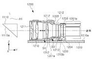
도 11은 광의 방향이 한차례 전환되는 카메라 모듈(2000)을 개략적으로 도시한 것이다.11 schematically illustrates a
도 11의 카메라 모듈(2000)은 도 1 내지 도 10의 카메라 모듈(1000)과 달리 반사 모듈(1400)을 포함하지 않는다. 폴디드 모듈(2100)에 입사된 광(L)은 한차례만 대략 90도 전환되어 이미지 센서로 도달한다.Unlike the
도 1 내지 도 10에서 설명된 렌즈 모듈(1200)이나 폴디드 모듈(1100)은 도 11에 도시된 카메라 모듈(2000)에도 마찬가지로 적용될 수 있다.The
도 4 내지 도 6에서 설명된 렌즈 모듈(1200)이 도 11의 카메라 모듈(2000)에 적용될 수 있다. 예를 들어, 렌즈 모듈(2200)은 렌즈 배럴, 및 렌즈 홀더를 포함하고, 렌즈 홀더는 비대칭적으로 형성될 수 있다.The
도 12는 일 실시 예에서 카메라 모듈(1000)을 포함하는 휴대장치를 도시한다.12 illustrates a portable device including a
도 12를 참고하면, 본 발명의 일 실시 예에 따른 휴대용 전자기기(1)는 제1카메라 모듈(100)(예를 들어, 도 1의 카메라 모듈(1000) 또는 도 11의 카메라 모듈(2000))이 장착된 이동 통신 단말기, 스마트 폰, 태블릿 PC 등의 휴대 가능한 전자기기일 수 있다.Referring to FIG. 12 , a portable electronic device 1 according to an embodiment of the present invention includes a first camera module 100 (eg, the
본 실시 예에서, 제1카메라 모듈(100)에서 렌즈 모듈의 광축은 휴대용 전자기기(1)의 두께 방향에 수직하는 방향을 향할 수 있다.In this embodiment, the optical axis of the lens module in the
따라서, 제1카메라 모듈(100)이 자동 초점 조정(Auto Focusing, 이하 AF), 줌(Zoom) 및 손떨림방지(Optical Image Stabilizing, 이하 OIS) 등의 기능을 구비하더라도 휴대용 전자기기(1)의 두께가 증가하지 않도록 할 수 있다. 이에 따라, 휴대용 전자기기(1)의 소형화가 가능하다.Therefore, even if the
일 실시 예에서 휴대용 전자기기(1)에는 피사체를 촬영할 수 있도록 2개 이상의 카메라 모듈들이 장착될 수 있다. 일 예로, 휴대용 전자기기는 제1카메라 모듈(100)과 함께 제2카메라 모듈(200)을 추가로 구비할 수 있다.In one embodiment, two or more camera modules may be mounted on the portable electronic device 1 to capture a subject. For example, the portable electronic device may further include a
2개의 카메라 모듈들(100, 200)을 사용하는 경우에는, 2개의 카메라 모듈들(100, 200)에 광이 입사되는 입사구들은 최대한 서로 인접하게 배치될 수 있다. 도시된 실시 예와 달리, 제1카메라 모듈(100)과 제2카메라 모듈(200)의 위치는 서로 바뀔 수 있다.In the case of using the two
일 실시 예에서 제1카메라 모듈(100)과 제2카메라 모듈(200)은 서로 다른 화각을 가지도록 구성될 수 있다. 제1카메라 모듈(100)은 상대적으로 화각이 좁게 구성(예를 들어, 망원 카메라)되고, 제2카메라 모듈(200)은 상대적으로 화각이 넓게 구성(예를 들어, 광각 카메라)될 수 있다.In one embodiment, the
1000: 카메라 모듈
1100: 폴디드 모듈
1200: 렌즈 모듈
1300: 이미지 센서 모듈
1400: 반사 모듈
1500: 스타퍼1000: camera module
1100: folded module
1200: lens module
1300: image sensor module
1400: reflection module
1500: stopper
Claims (17)
Translated fromKorean상기 하우징 내에서 광축 방향으로 이동하도록 구성된 렌즈 홀더; 및
상기 렌즈 홀더에 결합된 렌즈 배럴;를 포함하고,
상기 렌즈 홀더는 일측면에서 상기 광축 방향으로 연장하는 제1지지구조물, 및 상기 제1지지구조물의 반대편 측면에 위치되고 상기 광축 방향으로 연장하는 제2지지구조물을 포함하고,
상기 제1지지구조물은 상기 제2지지구조물보다 상기 광축 방향으로 더 돌출된 연장부를 포함하며,
상기 렌즈 홀더는 상기 광축에 수직인 방향으로 지지되고, 상기 렌즈 홀더를 지지하는 적어도 하나의 지지점은 상기 연장부에 위치되는, 카메라 모듈.housing;
a lens holder configured to move in an optical axis direction within the housing; and
Includes; a lens barrel coupled to the lens holder,
The lens holder includes a first support structure extending in the optical axis direction from one side, and a second support structure located on a side opposite to the first support structure and extending in the optical axis direction,
The first support structure includes an extension that protrudes further in the optical axis direction than the second support structure,
The camera module of claim 1 , wherein the lens holder is supported in a direction perpendicular to the optical axis, and at least one fulcrum supporting the lens holder is located in the extension part.
상기 렌즈 배럴은 상기 광축을 포함하고 상기 제1지지구조물과 상기 제2지지구조물이 대향하는 방향에 수직인 면을 기준으로 대칭적으로 구성된, 카메라 모듈.According to claim 1,
The lens barrel is configured symmetrically with respect to a plane perpendicular to a direction in which the first support structure and the second support structure face each other and include the optical axis.
상기 렌즈 배럴은 상기 광축을 포함하고 상기 제1지지구조물과 상기 제2지지구조물이 대향하는 방향에 나란한 면을 기준으로 대칭적으로 구성된, 카메라 모듈.According to claim 1,
wherein the lens barrel includes the optical axis and is configured symmetrically with respect to a surface parallel to directions in which the first support structure and the second support structure face each other.
상기 적어도 하나의 지지점은 상기 하우징과 상기 연장부 사이에 개재된 볼부재에 의해 제공되는, 카메라 모듈.According to claim 1,
The at least one support point is provided by a ball member interposed between the housing and the extension, the camera module.
상기 광축 방향으로 연장하고, 상기 볼부재를 적어도 일부 수용하는 가이드홈이 상기 연장부에 제공되는, 카메라 모듈.According to claim 5,
A camera module, wherein a guide groove extending in the optical axis direction and accommodating at least a portion of the ball member is provided in the extension portion.
상기 렌즈 홀더는 상기 하우징의 바닥면과 사이에 배치된 제1볼부재, 제2볼부재, 및 제3볼부재에 의해 적어도 일부 지지되고,
상기 제1볼부재는 상기 제2지지구조물과 상기 바닥면 사이에 배치되고, 상기 제2볼부재는 상기 제1지지구조물 중 상기 제2지지구조물과 대응하는 부분과 상기 바닥면 사이에 배치되고, 상기 제3볼부재는 상기 제1지지구조물 중 상기 연장부와 상기 바닥면 사이에 배치되는, 카메라 모듈.According to claim 1,
The lens holder is at least partially supported by a first ball member, a second ball member, and a third ball member disposed between the bottom surface of the housing,
The first ball member is disposed between the second support structure and the bottom surface, and the second ball member is disposed between a portion corresponding to the second support structure and the bottom surface of the first support structure, The third ball member is disposed between the extension part and the bottom surface of the first support structure, the camera module.
상기 렌즈 홀더의 상기 바닥면을 향하는 부분에 구비된 제1자성부재; 및
상기 바닥면에 상기 제1자성부재와 대향하게 배치된 제2자성부재를 더 포함하고,
상기 제1자성부재와 상기 제2자성부재 사이에 자기적 인력이 생기는, 카메라 모듈.According to claim 7,
a first magnetic member provided on a portion of the lens holder facing the bottom surface; and
Further comprising a second magnetic member disposed opposite to the first magnetic member on the bottom surface,
The camera module, wherein a magnetic attraction is generated between the first magnetic member and the second magnetic member.
상기 제1자성부재는 상기 제1볼부재, 상기 제2볼부재, 상기 제3볼부재에 각각 제공되는 지지점들로 둘러싸인 영역 내부에 위치되는, 카메라 모듈.According to claim 8,
The first magnetic member is located inside an area surrounded by support points provided to the first ball member, the second ball member, and the third ball member, respectively, the camera module.
상기 렌즈 홀더는 상기 제1지지구조물과 상기 제2지지구조물 사이를 연결하고, 상기 바닥면에 대향하는 하부구조물을 더 포함하고, 상기 제1자성부재는 상기 하부구조물에 구비되는, 카메라 모듈.According to claim 8,
The lens holder further includes a lower structure connecting between the first supporting structure and the second supporting structure and facing the bottom surface, wherein the first magnetic member is provided in the lower structure.
상기 렌즈 배럴은 상기 바닥면과 대향하는 제1면, 및 상기 바닥면과 대향하되 상기 제1면보다 상기 바닥면으로부터 더 이격된 제2면을 포함하고, 상기 하부구조물은 상기 제2면과 상기 바닥면 사이에 배치되는, 카메라 모듈.According to claim 10,
The lens barrel includes a first surface facing the bottom surface and a second surface facing the bottom surface but spaced further from the bottom surface than the first surface, and the lower structure includes the second surface and the bottom surface. A camera module, disposed between the faces.
상기 하우징에 구비되고, 상기 연장부의 단부와 상기 광축 방향으로 대향하도록 배치된 스토퍼를 더 포함하는, 카메라 모듈.According to claim 1,
The camera module further includes a stopper provided in the housing and disposed to face an end of the extension part in the optical axis direction.
상기 렌즈 홀더에 구비되고, 상기 렌즈 배럴의 일측에 배치되고, 상기 렌즈 배럴을 통과한 광이 통과하도록 구성된 입사공을 포함하는 배플을 더 포함하는, 카메라 모듈.According to claim 1,
The camera module further includes a baffle provided in the lens holder, disposed on one side of the lens barrel, and including an incident hole configured to pass light passing through the lens barrel.
일방향으로 입사한 광의 방향을 상기 렌즈 배럴을 향해 변환하도록 구성된 제1반사부재를 더 포함하는, 카메라 모듈.According to claim 1,
The camera module further comprises a first reflecting member configured to convert a direction of light incident in one direction toward the lens barrel.
결상면이 상기 렌즈 배럴의 상기 광축과 교차하는 방향을 향하도록 배치된 이미지 센서; 및
상기 렌즈 배럴을 통과한 광을 상기 결상면을 향해 변환하도록 구성된 제2반사부재;를 더 포함하는, 카메라 모듈.According to claim 1,
an image sensor disposed such that an imaging plane faces a direction crossing the optical axis of the lens barrel; and
A second reflective member configured to convert the light passing through the lens barrel toward the imaging plane; further comprising a camera module.
상기 하우징 내에서 광축 방향으로 이동하도록 구성된 렌즈 홀더;
상기 렌즈 홀더에 결합된 렌즈 배럴;
제1방향으로 입사한 광의 방향을 상기 광축 방향으로 변환하도록 구성된 제1반사부재;
결상면이 상기 렌즈 배럴의 상기 광축과 교차하는 방향을 향하도록 배치된 이미지 센서; 및
상기 렌즈 배럴을 통과한 광을 상기 결상면을 향해 변환하도록 구성된 제2 반사부재;를 포함하고,
상기 렌즈 배럴은 상기 광축을 포함하고, 상기 제1방향과 나란한 제1면을 기준으로 대칭적인 형태로 제공되고, 상기 렌즈 홀더는 상기 제1면을 기준으로 비대칭적인 형태로 제공되는, 카메라 모듈.housing;
a lens holder configured to move in an optical axis direction within the housing;
a lens barrel coupled to the lens holder;
a first reflective member configured to convert a direction of light incident in a first direction into a direction of the optical axis;
an image sensor disposed such that an imaging plane faces a direction crossing the optical axis of the lens barrel; and
A second reflection member configured to convert the light passing through the lens barrel toward the image plane;
The lens barrel includes the optical axis and is provided in a symmetrical form with respect to a first surface parallel to the first direction, and the lens holder is provided in an asymmetrical form with respect to the first surface.
상기 렌즈 배럴은 상기 광축을 포함하고, 상기 제1방향과 수직인 제2면을 기준으로 대칭적인 형태로 제공되는, 카메라 모듈.
According to claim 16,
The lens barrel includes the optical axis and is provided in a symmetrical form with respect to a second surface perpendicular to the first direction.
Priority Applications (3)
| Application Number | Priority Date | Filing Date | Title |
|---|---|---|---|
| US17/397,014US11982924B2 (en) | 2020-09-29 | 2021-08-09 | Camera module |
| CN202122340417.0UCN215813690U (en) | 2020-09-29 | 2021-09-26 | Camera module and electronic device including the same |
| CN202111139226.6ACN114355546B (en) | 2020-09-29 | 2021-09-26 | Camera module and electronic device including the same |
Applications Claiming Priority (2)
| Application Number | Priority Date | Filing Date | Title |
|---|---|---|---|
| KR1020200127467 | 2020-09-29 | ||
| KR20200127467 | 2020-09-29 |
Publications (2)
| Publication Number | Publication Date |
|---|---|
| KR20220043815A KR20220043815A (en) | 2022-04-05 |
| KR102488750B1true KR102488750B1 (en) | 2023-01-17 |
Family
ID=81181755
Family Applications (1)
| Application Number | Title | Priority Date | Filing Date |
|---|---|---|---|
| KR1020210010811AActiveKR102488750B1 (en) | 2020-09-29 | 2021-01-26 | camera module |
Country Status (1)
| Country | Link |
|---|---|
| KR (1) | KR102488750B1 (en) |
Families Citing this family (2)
| Publication number | Priority date | Publication date | Assignee | Title |
|---|---|---|---|---|
| JP7277810B2 (en)* | 2021-08-30 | 2023-05-19 | ミツミ電機株式会社 | Optical actuator, camera module, and camera mounting device |
| KR102842390B1 (en)* | 2023-04-26 | 2025-08-05 | (주)에이피텍 | Ois baffle attach system |
Family Cites Families (4)
| Publication number | Priority date | Publication date | Assignee | Title |
|---|---|---|---|---|
| KR101793313B1 (en)* | 2010-10-12 | 2017-11-02 | 트리프로그 디벨롭먼츠, 인크. | Housing for encasing an electronic device |
| KR102391155B1 (en)* | 2018-01-26 | 2022-04-29 | 애플 인크. | Foldable camera with actuator for moving optics |
| KR102494681B1 (en)* | 2018-04-13 | 2023-02-02 | 삼성전자주식회사 | Camera assembly and Electronic device having the same |
| KR102370583B1 (en)* | 2018-10-26 | 2022-03-07 | 삼성전기주식회사 | Camera module |
- 2021
- 2021-01-26KRKR1020210010811Apatent/KR102488750B1/enactiveActive
Also Published As
| Publication number | Publication date |
|---|---|
| KR20220043815A (en) | 2022-04-05 |
Similar Documents
| Publication | Publication Date | Title |
|---|---|---|
| KR102737549B1 (en) | Camera module | |
| KR102338257B1 (en) | Camera module | |
| KR20180102946A (en) | Mirror Module for OIS and Camera module including the same | |
| KR102641342B1 (en) | camera module | |
| KR20120033279A (en) | Imaging unit | |
| KR102579632B1 (en) | camera module | |
| KR20220043879A (en) | camera module | |
| US20220317412A1 (en) | Actuator for driving zoom | |
| CN114730122B (en) | Reflector actuator and camera module including the reflector actuator | |
| KR102488750B1 (en) | camera module | |
| KR102233934B1 (en) | Mirror Module for OIS and Camera module including the same | |
| CN215813690U (en) | Camera module and electronic device including the same | |
| CN114167667B (en) | Camera module and portable electronic device | |
| KR102527321B1 (en) | camera module | |
| KR102550161B1 (en) | camera module | |
| KR20230089670A (en) | Camera module | |
| KR102712636B1 (en) | Camera module | |
| KR102312300B1 (en) | Actuator for folded zoom camera module and Folded zoom camera module containing the same | |
| CN117881993A (en) | Lens assembly | |
| KR20220074675A (en) | Camera actuator and Folded zoom camera module containing the same | |
| KR102574418B1 (en) | Camera Module | |
| CN219625850U (en) | Camera module | |
| US20240134143A1 (en) | Actuator for camera | |
| JP2023139801A (en) | Camera module | |
| KR20230028832A (en) | Camera Module |
Legal Events
| Date | Code | Title | Description |
|---|---|---|---|
| PA0109 | Patent application | Patent event code:PA01091R01D Comment text:Patent Application Patent event date:20210126 | |
| PA0201 | Request for examination | ||
| PG1501 | Laying open of application | ||
| E902 | Notification of reason for refusal | ||
| PE0902 | Notice of grounds for rejection | Comment text:Notification of reason for refusal Patent event date:20220415 Patent event code:PE09021S01D | |
| E701 | Decision to grant or registration of patent right | ||
| PE0701 | Decision of registration | Patent event code:PE07011S01D Comment text:Decision to Grant Registration Patent event date:20221011 | |
| GRNT | Written decision to grant | ||
| PR0701 | Registration of establishment | Comment text:Registration of Establishment Patent event date:20230111 Patent event code:PR07011E01D | |
| PR1002 | Payment of registration fee | Payment date:20230112 End annual number:3 Start annual number:1 | |
| PG1601 | Publication of registration |