KR102487892B1 - Ship centric direct communication and method of performing thereof - Google Patents
Ship centric direct communication and method of performing thereofDownload PDFInfo
- Publication number
- KR102487892B1 KR102487892B1KR1020220139500AKR20220139500AKR102487892B1KR 102487892 B1KR102487892 B1KR 102487892B1KR 1020220139500 AKR1020220139500 AKR 1020220139500AKR 20220139500 AKR20220139500 AKR 20220139500AKR 102487892 B1KR102487892 B1KR 102487892B1
- Authority
- KR
- South Korea
- Prior art keywords
- pilot
- pilots
- data
- noise variance
- channel
- Prior art date
- Legal status (The legal status is an assumption and is not a legal conclusion. Google has not performed a legal analysis and makes no representation as to the accuracy of the status listed.)
- Active
Links
Images


Classifications
- H—ELECTRICITY
- H04—ELECTRIC COMMUNICATION TECHNIQUE
- H04W—WIRELESS COMMUNICATION NETWORKS
- H04W74/00—Wireless channel access
- H04W74/002—Transmission of channel access control information
- H—ELECTRICITY
- H04—ELECTRIC COMMUNICATION TECHNIQUE
- H04L—TRANSMISSION OF DIGITAL INFORMATION, e.g. TELEGRAPHIC COMMUNICATION
- H04L25/00—Baseband systems
- H04L25/02—Details ; arrangements for supplying electrical power along data transmission lines
- H04L25/0202—Channel estimation
- H04L25/0224—Channel estimation using sounding signals
- H04L25/0228—Channel estimation using sounding signals with direct estimation from sounding signals
- H04L25/023—Channel estimation using sounding signals with direct estimation from sounding signals with extension to other symbols
- H04L25/0232—Channel estimation using sounding signals with direct estimation from sounding signals with extension to other symbols by interpolation between sounding signals
- H—ELECTRICITY
- H04—ELECTRIC COMMUNICATION TECHNIQUE
- H04L—TRANSMISSION OF DIGITAL INFORMATION, e.g. TELEGRAPHIC COMMUNICATION
- H04L25/00—Baseband systems
- H04L25/02—Details ; arrangements for supplying electrical power along data transmission lines
- H04L25/0202—Channel estimation
- H04L25/0224—Channel estimation using sounding signals
- H04L25/0228—Channel estimation using sounding signals with direct estimation from sounding signals
- H—ELECTRICITY
- H04—ELECTRIC COMMUNICATION TECHNIQUE
- H04J—MULTIPLEX COMMUNICATION
- H04J13/00—Code division multiplex systems
- H04J13/0007—Code type
- H04J13/0022—PN, e.g. Kronecker
- H—ELECTRICITY
- H04—ELECTRIC COMMUNICATION TECHNIQUE
- H04L—TRANSMISSION OF DIGITAL INFORMATION, e.g. TELEGRAPHIC COMMUNICATION
- H04L25/00—Baseband systems
- H04L25/02—Details ; arrangements for supplying electrical power along data transmission lines
- H04L25/0202—Channel estimation
- H04L25/022—Channel estimation of frequency response
- H—ELECTRICITY
- H04—ELECTRIC COMMUNICATION TECHNIQUE
- H04L—TRANSMISSION OF DIGITAL INFORMATION, e.g. TELEGRAPHIC COMMUNICATION
- H04L25/00—Baseband systems
- H04L25/02—Details ; arrangements for supplying electrical power along data transmission lines
- H04L25/0202—Channel estimation
- H04L25/0224—Channel estimation using sounding signals
Landscapes
- Engineering & Computer Science (AREA)
- Computer Networks & Wireless Communication (AREA)
- Signal Processing (AREA)
- Power Engineering (AREA)
- Mobile Radio Communication Systems (AREA)
- Digital Transmission Methods That Use Modulated Carrier Waves (AREA)
Abstract
Description
Translated fromKorean본 발명은 선박 중심 직접 통신 시스템 및 이의 실행 방법에 관한 것으로, 보다 구체적으로 의사 잡음 시퀀스(pseudo-random noise sequence)에 원래의 신호를 입력시키면 주파수당 전력밀도가 낮아진 확산대역 스펙트럼 신호를 얻을 수 있고 수신측에서도 동일한 시퀀스의 의사잡음 시퀀스를 사용하면 원 신호를 재생할 수 있도록 하는 선박 중심 직접 통신 시스템 및 이의 실행 방법에 관한 것이다.The present invention relates to a ship-centered direct communication system and a method for implementing the same, and more specifically, when an original signal is input to a pseudo-random noise sequence, a spread-band spectrum signal with a lowered power density per frequency can be obtained, A ship-centered direct communication system capable of reproducing an original signal when a pseudonoise sequence of the same sequence is used on a receiving side, and a method for executing the same.
SC-FDE (Single Carrier Frequency Domain Equalization, 단일 반송파 주파수 영역 등화) 전송방식은 기존의 단일 반송파 방식에 Cyclic Prefix(CP)를 추가하여 전송하는 방식이다.The SC-FDE (Single Carrier Frequency Domain Equalization) transmission method is a method of transmitting by adding a Cyclic Prefix (CP) to the existing single carrier method.
따라서, 수신기에서 복잡한 시간영역 채널등화 방식을 사용하지 않고 주파수 영역에서 채널 등화를 가능하게 하여 주파수 선택적 특성을 갖는 페이딩 채널에서 비교적 간단하게 무선채널 왜곡을 보상할 수 있어 광대역 무선통신 시스템에서 일부 사용되고 있다.Therefore, the receiver enables channel equalization in the frequency domain without using a complicated time domain channel equalization method, and relatively easily compensates for radio channel distortion in a fading channel having a frequency selective characteristic, and is partially used in a broadband wireless communication system. .
SC-FDE의 채널보상 방식은 Orthogonal Frequency Division Multiplexing (OFDM)의 방식과 유사하나 OFDM은 신호의 Peak-to-Average Power Ratio (PAPR)가 크기 때문에 송신기의 전력효율이 나빠 전력소모가 큰 문제가 있다. 이와 같은 문제는 특히 배터리로 동작하는 통신기기에서 더 심각하다는 문제점이 있다.The channel compensation method of SC-FDE is similar to that of Orthogonal Frequency Division Multiplexing (OFDM). However, since OFDM has a large Peak-to-Average Power Ratio (PAPR) of the signal, power efficiency of the transmitter is poor and power consumption is high. . Such a problem is particularly serious in a battery operated communication device.
하지만, SC-FDE 방식은 단일 반송파 전송방식이기 때문에 PAPR이 OFDM에 비해 상대적으로 작고 결국 송신기의 전력소모를 줄일 수 있어 배터리로 동작하는 시스템에 더 적합하다.However, since the SC-FDE scheme is a single carrier transmission scheme, the PAPR is relatively small compared to OFDM, and consequently power consumption of the transmitter can be reduced, so it is more suitable for a battery operated system.
한편, SC-FDE 방식은 단일 반송파 주파수를 사용하므로 복수의 수신기들로 하향 링크 전송 시에는 상호 간 간섭이나 다중 경로 페이딩이 발생할 수 있다는 문제점이 있다. 따라서, 현재 무선 통신 시스템에서는 하향링크에서는 OFDM 방식을 이용하고 상향링크에서는 SC-FDMA 방식을 사용하는 절충적인 형태를 취한다. 하지만, 지상국 장치와 무인기 간의 통신 링크에서는 어떠한 통신 방식을 사용할지에 대한 프로토콜이 무인기에 따라 상이하다는 문제점이 있다.Meanwhile, since the SC-FDE scheme uses a single carrier frequency, there is a problem in that mutual interference or multi-path fading may occur during downlink transmission to a plurality of receivers. Therefore, in a current wireless communication system, an OFDM method is used in downlink and an SC-FDMA method is used in uplink. However, there is a problem in that the protocol for which communication method is to be used in the communication link between the ground station device and the UAV is different depending on the UAV.
한편, 채널 추정을 위해서 송신기는 파일럿 신호를 전송해야 한다. 수신기에서는 송신기가 전송한 파일럿이 왜곡되어 도착한 것을 보고 채널을 추정할 수 있다. 파일럿은 주기적으로 전송해야 하는데 이는 통신기기가 이동 중이거나 주면 환경의 변화가 있을 때 송 수신 간 무선 채널 특성이 시간에 따라 변할 수 있으므로 주기적으로 채널특성을 추정하고 갱신해야 하기 위해서 주기적인 파일럿이 필요하기 때문이다.Meanwhile, for channel estimation, a transmitter needs to transmit a pilot signal. The receiver can estimate the channel by seeing that the pilot transmitted by the transmitter arrives distorted. Pilots must be transmitted periodically, which means that radio channel characteristics between transmission and reception can change over time when the communication device is moving or there is a change in the environment. Therefore, periodic pilots are necessary to periodically estimate and update channel characteristics because it does
따라서 빠르게 이동하는 환경에서는 더 자주 파일럿을 전송해야 하고 이는 파일럿에 의한 오버헤드가 증가하여 실제 사용자 전송속도가 저하되는 문제점이 있다.Therefore, pilots must be transmitted more frequently in a fast-moving environment, which increases the overhead caused by pilots, thereby reducing the actual user transmission rate.
한국등록특허 제10-1275852호는 UW(UNIQUE-WORD)를 사용하는 SC-FD 기반의 송수신 장치 및 방법에 관한 것으로, 입력 데이터를 소정의 변조 방식으로 변조하여 데이터 심볼을 출력하는 변조부 및 상기 데이터 심볼의 앞단에 두 개의 UW(unique-word)를 추가하고 상기 데이터 심볼의 뒷단에 한개의 UW를 추가하는 UW 삽입부를 포함하는 내용이 개시되어 있다.Korean Patent Registration No. 10-1275852 relates to an SC-FD-based transmission and reception apparatus and method using UW (UNIQUE-WORD), a modulator for outputting data symbols by modulating input data with a predetermined modulation method, and the above Disclosed is a content including a UW insertion unit that adds two unique-words (UWs) to a front end of a data symbol and adds one UW to a rear end of the data symbol.
한국공개특허 제10-2022-0111381호는 SC-FDE 방식의 위상 잡음 보상을 위한 송수신 방법 및 이를 위한 장치에 관한 것으로, 밀리미터파 이상의 통신 대역에서 SC-FDE(Single Carrier-Frequency Domain Equalizer) 방식의 데이터 송수신에서 위상 잡음을 추정하고 보상하기 위해 데이터를 송수신한다는 내용이 개시되어 있다.Korean Patent Publication No. 10-2022-0111381 relates to a transmission/reception method for phase noise compensation of the SC-FDE method and an apparatus therefor. Disclosed is data transmission and reception in order to estimate and compensate for phase noise in data transmission and reception.
한국등록특허 제10-0989098호는 SC-FDE 시스템에서 GMSK 변조에 기초한 데이터 프레임 생성 방법에 관한 것으로, 제1 데이터 심볼 열과 제2 데이터 심볼 열에 각각 제1 플러시 심볼 및 제로 심볼과 제2 플러시 심볼 및 제로 심볼을 결합함으로써 위상의 불연속성을 방지할 수 있다는 내용이 개시되어 있다.Korean Patent Registration No. 10-0989098 relates to a method for generating a data frame based on GMSK modulation in an SC-FDE system, and a first flush symbol, a zero symbol and a second flush symbol are respectively assigned to a first data symbol string and a second data symbol string, and It is disclosed that phase discontinuity can be prevented by combining zero symbols.
한국등록특허 제10-1858993호는 SC-FDE 전송 구조에서 파일럿 오버헤드 감소 방법에 관한 것으로, 송신기에서는 파일럿을 가끔 전송하며 수신기에서는 파일럿을 이용하여 채널을 추정하며 파일럿과 파일럿 사이의 채널은 선형보간법을 이용하여 채널을 추정한다는 내용이 개시되어 있다.Korean Patent Registration No. 10-1858993 relates to a method for reducing pilot overhead in an SC-FDE transmission structure. The content of estimating a channel by using is disclosed.
본 발명은 기존 해상 모바일 서비스에 할당된 300㎒ 이하의 대역보다 높은 고 주파수(이하 MX) 기반 광대역 통신 기술을 활용하는 MX-S2X 통신을 개발하기 위해 고 주파수 대역을 해상에서 사용할 경우 예상되는 해수면에 의한 다중경로 페이딩 영향을 최소화할 수 있도록 하는 선박 중심 직접 통신 시스템 및 이의 실행 방법을 제공하는 것을 목적으로 한다.The present invention is to develop MX-S2X communication that utilizes high-frequency (hereafter MX)-based broadband communication technology higher than the band of 300 MHz or less allocated to existing maritime mobile services. An object of the present invention is to provide a ship-centered direct communication system and a method for implementing the same that can minimize the multipath fading effect caused by the present invention.
또한, 본 발명은 의사 잡음 시퀀스(pseudo-random noise sequence)에 원래의 신호를 입력시키면 주파수당 전력밀도가 낮아진 확산대역 스펙트럼 신호를 얻을 수 있고 수신측에서도 동일한 시퀀스의 의사잡음 시퀀스를 사용하면 원 신호를 재생할 수 있어 변조의 효율성이 좋고 신호의 동기가 빠르며 낮아진 전력밀도에 대역내 간섭이 적은 선박 중심 직접 통신 시스템 및 이의 실행 방법을 제공하는 것을 목적으로 한다.In addition, according to the present invention, when an original signal is input to a pseudo-random noise sequence, a spread-band spectrum signal having a lowered power density per frequency can be obtained. It is an object of the present invention to provide a ship-centered direct communication system with high modulation efficiency, fast signal synchronization, low power density and low in-band interference, and a method for implementing the same.
본 발명의 목적들은 이상에서 언급한 목적으로 제한되지 않으며, 언급되지 않은 본 발명의 다른 목적 및 장점들은 하기의 설명에 의해서 이해될 수 있고, 본 발명의 실시예에 의해 보다 분명하게 이해될 것이다. 또한, 본 발명의 목적 및 장점들은 특허 청구 범위에 나타낸 수단 및 그 조합에 의해 실현될 수 있음을 쉽게 알 수 있을 것이다.The objects of the present invention are not limited to the above-mentioned objects, and other objects and advantages of the present invention not mentioned above can be understood by the following description and will be more clearly understood by the examples of the present invention. It will also be readily apparent that the objects and advantages of the present invention may be realized by means of the instrumentalities and combinations indicated in the claims.
이러한 목적을 달성하기 위한 데이터 송신 장치 및 데이터 수신 장치를 포함하는 선박 중심 직접 통신 시스템은 슬롯 시간에 따라 생성된 복수의 슬롯, 파일럿 전송 주기에 따라 상기 복수의 슬롯 각각의 특정 위치에 배치된 채널 추정을 위한 복수의 파일럿 및 상기 복수의 파일럿 사이에 배치된 데이터 심볼로 구성된 전송 프레임을 링크 채널을 통해 데이터 수신 장치에 송신하는 데이터 송신 장치 및 상기 데이터 송신 장치로부터 전송 프레임을 수신하면 상기 전송 프레임의 복수의 슬롯 각각에 대한 복수의 파일럿을 이용하여 주파수 영역에서 채널 추정후 선형 보간하여 상기 복수의 파일럿 사이에 있는 데이터에 대한 채널 보상을 실행하고, 상기 채널 보상된 신호를 다시 시간 영역 심볼로 변환하는 데이터 수신 장치를 포함한다.A ship-centered direct communication system including a data transmission device and a data reception device for achieving this object estimates a plurality of slots generated according to slot time and a channel arranged at a specific position of each of the plurality of slots according to a pilot transmission period. A data transmission device that transmits a transmission frame composed of a plurality of pilots for and data symbols disposed between the plurality of pilots to a data reception device through a link channel, and when receiving a transmission frame from the data transmission device, a plurality of the transmission frames After estimating a channel in the frequency domain using a plurality of pilots for each slot of , linear interpolation is performed to perform channel compensation for data between the plurality of pilots, and data for converting the channel compensated signal back into time domain symbols. Including the receiving device.
또한 이러한 목적을 달성하기 위한 선박 중심 직접 통신 시스템의 실행 방법은 데이터 송신 장치가 슬롯 시간에 따라 생성된 복수의 슬롯, 파일럿 전송 주기에 따라 상기 복수의 슬롯 각각의 특정 위치에 배치된 채널 추정을 위한 복수의 파일럿 및 상기 복수의 파일럿 사이에 배치된 데이터 심볼로 구성된 전송 프레임을 링크 채널을 통해 데이터 수신 장치에 송신하는 단계, 상기 데이터 수신 장치가 상기 전송 프레임을 수신하면 상기 전송 프레임의 복수의 슬롯 각각에 대한 복수의 파일럿을 이용하여 주파수 영역에서 채널 추정후 선형 보간하여 상기 복수의 파일럿 사이에 있는 데이터에 대한 채널 보상을 실행하는 단계 및 상기 데이터 수신 장치가 상기 채널 보상된 신호를 다시 시간 영역 심볼로 변환하는 단계를 포함한다.In addition, a method for implementing a ship-centered direct communication system to achieve this object is a method for estimating a channel in which a data transmission device is disposed at a specific position of each of a plurality of slots according to a plurality of slots generated according to the slot time and a pilot transmission period. Transmitting a transmission frame composed of a plurality of pilots and data symbols disposed between the plurality of pilots to a data receiving apparatus through a link channel, wherein when the data receiving apparatus receives the transmission frame, each of a plurality of slots of the transmission frame Executing channel compensation for data between the plurality of pilots by performing linear interpolation after channel estimation in the frequency domain using a plurality of pilots for , and the data receiving apparatus transforms the channel-compensated signal into time domain symbols again. Including conversion.
전술한 바와 같은 본 발명에 의하면, 기존 해상 모바일 서비스에 할당된 300㎒ 이하의 대역보다 높은 고 주파수(이하 MX) 기반 광대역 통신 기술을 활용하는 MX-S2X 통신을 개발하기 위해 고 주파수 대역을 해상에서 사용할 경우 예상되는 해수면에 의한 다중경로 페이딩 영향을 최소화할 수 있다는 장점이 있다.According to the present invention as described above, in order to develop MX-S2X communication that utilizes a high frequency (hereafter MX) based broadband communication technology higher than the band of 300 MHz or less allocated to existing maritime mobile services, a high frequency band is used at sea. When used, it has the advantage of minimizing the multipath fading effect caused by the expected sea level.
또한 본 발명에 의하면, 의사 잡음 시퀀스(pseudo-random noise sequence)에 원래의 신호를 입력시키면 주파수당 전력밀도가 낮아진 확산대역 스펙트럼 신호를 얻을 수 있고 수신측에서도 동일한 시퀀스의 의사잡음 시퀀스를 사용하면 원 신호를 재생할 수 있어 변조의 효율성이 좋고 신호의 동기가 빠르며 낮아진 전력밀도에 대역내 간섭이 적다는 장점이 있다.In addition, according to the present invention, if an original signal is input to a pseudo-random noise sequence, a spread-spectrum signal with a lowered power density per frequency can be obtained. It has the advantage of high modulation efficiency, fast signal synchronization, low power density and low in-band interference.
도 1은 본 발명의 일 실시예에 따른 선박 중심 직접 통신 시스템을 설명하기 위한 네트워크 구성도이다.
도 2는 본 발명의 일 실시예에 따른 전송 프레임의 구조를 설명하기 위한 도면이다.
도 3은 본 발명의 일 실시예에 따른 인접 파일럿 사이의 선형 보간 채널 추정 과정을 설명하기 위한 도면이다.
도 4 내지 도 8은 본 발명의 일 실시예에 따른 선박 중심 직접 통신 시스템의 실험 결과를 설명하기 위한 그래프이다.1 is a network configuration diagram illustrating a ship-centered direct communication system according to an embodiment of the present invention.
2 is a diagram for explaining the structure of a transport frame according to an embodiment of the present invention.
3 is a diagram for explaining a process of linear interpolation channel estimation between adjacent pilots according to an embodiment of the present invention.
4 to 8 are graphs for explaining test results of a ship-centered direct communication system according to an embodiment of the present invention.
전술한 목적, 특징 및 장점은 첨부된 도면을 참조하여 상세하게 후술되며, 이에 따라 본 발명이 속하는 기술분야에서 통상의 지식을 가진 자가 본 발명의 기술적 사상을 용이하게 실시할 수 있을 것이다. 본 발명을 설명함에 있어서 본 발명과 관련된 공지 기술에 대한 구체적인 설명이 본 발명의 요지를 불필요하게 흐릴 수 있다고 판단되는 경우에는 상세한 설명을 생략한다. 이하, 첨부된 도면을 참조하여 본 발명에 따른 바람직한 실시예를 상세히 설명하기로 한다. 도면에서 동일한 참조부호는 동일 또는 유사한 구성요소를 가리키는 것으로 사용된다.The above objects, features and advantages will be described later in detail with reference to the accompanying drawings, and accordingly, those skilled in the art to which the present invention belongs will be able to easily implement the technical spirit of the present invention. In describing the present invention, if it is determined that the detailed description of the known technology related to the present invention may unnecessarily obscure the subject matter of the present invention, the detailed description will be omitted. Hereinafter, preferred embodiments according to the present invention will be described in detail with reference to the accompanying drawings. In the drawings, the same reference numerals are used to indicate the same or similar components.
종래의 MUNIN 프로젝트에서는 자율운항선박의 운용에 필요한 통신 요구사항을 분석하여 자율운항선박에 유인선박이 접근하는 랑데부(Rendezvous), 원격 제어(Remote Control), 정보 전송(Telemetry), 레이더 타겟(Radar Targets) 및 HD급 영상(HD Video)의 통신 하한 요구사항을 [표 1]과 같이 제시하였다.In the conventional MUNIN project, by analyzing the communication requirements necessary for the operation of autonomous ships, Rendezvous, remote control, telemetry, and radar targets where manned ships approach autonomous ships ) and HD Video communication lower limit requirements are presented as shown in [Table 1].
[표 1][Table 1]

[표 1]에서 제시한 랑데부, 원격제어 등 통신 요구속도는 기존 레거시 해상통신 시스템으로도 수용 가능한 낮은 수준으로 볼 수 있다. 하지만 최근 자율운항선박의 주변 상황 인식, 수집 정보 교환 수요, 디지털 트윈과 같은 육상 모니터링을 고려하면 요구속도는 Mbps급으로 크게 상향되어야 한다.The required communication speed such as rendezvous and remote control presented in [Table 1] can be considered as a low level that can be accommodated even by the existing legacy maritime communication system. However, considering the recent recognition of the surrounding situation of autonomous ships, demand for exchanging collected information, and land monitoring such as digital twin, the required speed should be greatly increased to the Mbps level.
해상 사고는 발생할 경우 대형 피해를 야기하므로 선박의 자율화, 자동화의 수준이 높을수록 더 높은 통신 성능을 가져야 하며 두 관계에 대한 비용-효율적 비교가 중요하다.Maritime accidents cause large-scale damage when they occur, so the higher the level of autonomy and automation of a ship, the higher the communication performance, and cost-effective comparison of the two relationships is important.
Namgung(2019)에서는 자율운항선박에 필요한 통신 용량을 산정하기 위해 통신 기지국 당 자율운항선박의 수, 주파수 사용 효율, 한 선박 당 요구되는 데이터 양 등을 고려한 산식을 이용하였다.Namgung (2019) used a formula that considered the number of autonomous ships per communication base station, frequency use efficiency, and the amount of data required per ship to calculate the communication capacity required for autonomous ships.
항구, 항만에서의 VTS 교신의 중요성, 충돌회피와 센서 정보 수집 등을 고려하여 자율운항선박 한 척 당약 0.8㎒의 스펙트럼이 요구됨을 제시하고 우리나라 주요 항구의 선박 분포를 통합 적용하여 다운링크 기준 11.3㎒, 상향 링크 기준 103.9㎒의 스펙트럼이 요구됨을 제시하였다.Considering the importance of VTS communication in ports and ports, collision avoidance and sensor information collection, it is proposed that about 0.8 MHz of spectrum is required for each autonomous vessel, and the downlink standard is 11.3 MHz by applying the distribution of vessels in major ports in Korea. , it was suggested that a spectrum of 103.9 MHz based on uplink is required.
육상으로 데이터를 전송하는 상향 링크에 대한 대역폭이 더 많이 요구되는 이유는 현시점에서 아직 자율운항선박의 자율성이 높지 않고 육상에서의 통제가 중요하기 때문인 것으로 해석할 수 있다.The reason why more bandwidth is required for the uplink that transmits data on land can be interpreted as the fact that the autonomy of autonomous ships is not high yet and control on land is important.
MX-S2X의 비면허대역 주파수 활용 가능성 관련하여 Kumar(2019) 연구에서는 V2X 통신 기술의 해상 사용 가능성과 함께 운용범위를 약 13km로 추정하였고, Kang et al.(2019)에서는 선박 운항자 중심의 네트워킹(S2X) 통신 기술의 개념 정립 필요성을 제기하면서 자율운항선박의 주변 상황 인식을 위한 선박 대 선박 통신에 활용 가능한 AIS 등의 포화상황으로 인해 추가적인 통신 기술의 선제적 도입의 필요성을 강조하였다.Regarding the possibility of using unlicensed band frequency of MX-S2X, a study by Kumar (2019) estimated the operating range as about 13km along with the possibility of using V2X communication technology at sea, and Kang et al. (2019) estimated ship operator-oriented networking ( While raising the need to establish the concept of S2X) communication technology, the need for preemptive introduction of additional communication technology was emphasized due to the saturation of AIS, which can be used for ship-to-ship communication for autonomous vessel awareness of the surrounding situation.
VDES(VHF Data Exchange System)는 선박과 선박, 선박과 해안국 간 AIS, ASM(Application Specific Message), VDE데이터를 송수신하는 차세대 해상무선통신시스템으로 국제표지항로협회(IALA)에서 개발된 기술 기준인 G1139를 기반으로 2021년 ITU-R M.2092의 권고안이 배포되었다.VDES (VHF Data Exchange System) is a next-generation maritime wireless communication system that transmits and receives AIS, ASM (Application Specific Message), and VDE data between ships and between ships and between ships and coast stations. Based on G1139, the recommendation of ITU-R M.2092 was distributed in 2021.
향후 해양 모빌리티와 자율운항선박 등의 활용성을 고려하면 MX-S2X 통신기술에 요구되는 데이터 전송률은 위의 [표 1]에 따라 최소 3Mbps급 이상이 되어야 한다. VDE 물리계층의 전송속도는 최대 307.2kbps이며, CRC를 제외한 순수 사용자 데이터만으로 계산한다면 실질적인 페이로드 전송속도는 최대 209.4kbps이다. VDE는 기존 AIS의 9.6kbps와 타 통신에 비하여 높은 통신 속도를 제공하나 자율운항선박을 위한 최소한의 요구 속도를 제공할 수 없는 수준이다Considering future utilization of marine mobility and autonomous ships, the data rate required for MX-S2X communication technology should be at least 3Mbps according to [Table 1] above. The transmission rate of the VDE physical layer is up to 307.2 kbps, and the actual payload transmission rate is up to 209.4 kbps if calculated only with pure user data excluding CRC. VDE provides a higher communication speed compared to 9.6kbps of the existing AIS and other communication, but it cannot provide the minimum required speed for autonomous ships.
해사 안전을 위한 통신은 다양한 형태의 모빌리티를 지원할 수 있는 통신 네트워크를 제공하여야 한다. VDES는 1분에 2,250 슬롯으로 구성되는 TDMA 네트워크를 제공하여 다수의 선박이 혼잡하게 몰리는 해역에서 슬롯 포화가 발생될 수 있다. 향후 예상되는 다수 해양 모빌리티의 네트워크 운용에 제한이 없도록 추가적인 슬롯 여유를 확보하는 등의 개선이 필요한 이유이다.Communication for maritime safety should provide a communication network that can support various types of mobility. VDES provides a TDMA network consisting of 2,250 slots per minute, so slot saturation can occur in sea areas where many ships are congested. This is why improvements such as securing additional slots are needed so that there are no restrictions on the network operation of many expected marine mobility in the future.
열악한 해상환경에서 다중경로 페이딩 영향은 반드시 극복되어야 하나 기존의 해상 통신기술에서는 충분한 검토가 이루어지지 않고 있는 실정이다. Kim et al.(2017), Ryu et al.(2018) 연구에서 VDE의 경우 다중경로 페이딩 영향 극복을 위해 Syncword 사용을 고려할 수 있으나 27개의 짧은 심볼로 인하여 충분한 성능을 제공할 수 없다. 그러므로 시간/주파수 동기 및 등화 기능을 위한 해상 환경에서의 영향을 분석하여 다중경로 페이딩 및 도플러 영향을 극복하기 위한 물리계층의 설계는 가장 중요한 연구개발 항목이다.In a harsh maritime environment, the effect of multipath fading must be overcome, but sufficient review has not been made in existing maritime communication technologies. In the studies of Kim et al. (2017) and Ryu et al. (2018), the use of Syncword can be considered to overcome the effect of multipath fading in the case of VDE, but it cannot provide sufficient performance due to 27 short symbols. Therefore, the design of the physical layer to overcome the multipath fading and Doppler effect by analyzing the effect in the marine environment for the time/frequency synchronization and equalization function is the most important research and development item.
따라서, 본 발명에서는 기존 해상 모바일 서비스에 할당된 300㎒ 이하의 대역보다 높은 고 주파수(이하 MX) 기반 광대역 통신 기술을 활용하는 MX-S2X 통신을 개발하기 위해 고 주파수 대역을 해상에서 사용할 경우 예상되는 해수면에 의한 다중경로 페이딩 영향을 최소화할 수 있도록 하는 방법을 제시한다.Therefore, in the present invention, in order to develop MX-S2X communication utilizing a high frequency (hereinafter referred to as MX)-based broadband communication technology higher than the band of 300 MHz or less allocated to existing maritime mobile services, expected when a high frequency band is used at sea A method to minimize the multipath fading effect caused by sea level is presented.
도 1은 본 발명의 일 실시예에 따른 선박 중심 직접 통신 시스템을 설명하기 위한 네트워크 구성도이다.1 is a network configuration diagram illustrating a ship-centered direct communication system according to an embodiment of the present invention.
도 1을 참조하면, 선박 중심 직접 통신 시스템은 데이터 송신 장치(100) 및 데이터 수신 장치(200)를 포함한다.Referring to FIG. 1 , the ship-centered direct communication system includes a
데이터 송신 장치(100)는 슬롯 시간에 따라 생성된 복수의 슬롯, 파일럿 전송 주기에 따라 상기 복수의 슬롯 각각의 특정 위치에 배치된 채널 추정을 위한 복수의 파일럿 및 상기 복수의 파일럿 사이에 배치된 데이터 심볼로 구성된 전송 프레임을 링크 채널을 통해 데이터 수신 장치(200)에 송신한다.The
먼저, 데이터 송신 장치(100)는 슬롯 시간에 따라 슬롯을 생성한다. 이때, 슬롯 시간은 본 발명의 일 실시예에 따른 선박 중심 직접 통신 시스템이 운용되는 통신 환경의 상관 시간을 고려하여 선박 이동 속도에 의해 산출된다.First, the
이때, 선박의 이동 속도 요구 사항을 최대 50㎞/h로 가정한 경우 최대 도플러 주파수는 111.11㎐이며, 상관 시간은 약 3.8㎳다. 따라서, 본 발명에서는 상관 시간을 고려해 슬롯 시간을 2㎳이다.At this time, assuming that the ship's moving speed requirement is up to 50 km/h, the maximum Doppler frequency is 111.11 Hz and the correlation time is about 3.8 ms. Therefore, in the present invention, the slot time is 2 ms considering the correlation time.
상기와 같이, 슬롯 시간이 2㎳인 경우 파일럿 전송이 여러 SC-FDE 심볼 단위로 가능하며 구조 또한 데이터 구조와 동일한 SC-FDE 심볼 형태로 적용 가능하다. 이런 경우, 데이터 심볼과 동일한 FFT 크기를 가지므로 FFT 출력 결과 전체를 채널 추정 및 보상에 사용할 수 있다.As described above, when the slot time is 2 ms, pilot transmission is possible in several SC-FDE symbol units, and the structure can also be applied to the same SC-FDE symbol form as the data structure. In this case, since it has the same FFT size as the data symbol, the entire FFT output result can be used for channel estimation and compensation.
그 후, 데이터 송신 장치(100)는 채널 추정을 위한 파일럿 전송 주기에 따라 슬롯에 파일럿을 배치한다. 이때, 채널 추정을 위한 파일럿 전송 주기는 최대 도플러 주파수 및 주파수 옵셋에 따라 결정된다.After that, the
주파수 옵셋의 요구 규격은 VDES를 참조하여 최대 주파수 옵셋 500㎐를 기준으로 적용하였다. 슬롯 시간에서 도플러 주파수를 포함한 최대 주파수 옵셋에 따른 위상 회전은 (111.11㎐ + 500㎐) × 2㎳ ×360도 = 약 440도로, 최대 추정 보상이 가능한 위상 360도를 과하므로 약 1㎳ 단위로 파일럿을 배치해 전송한다.The required standard of frequency offset was applied based on the maximum frequency offset of 500 Hz with reference to VDES. The phase rotation according to the maximum frequency offset including the Doppler frequency in the slot time is (111.11 Hz + 500 Hz) × 2 ms × 360 degrees = about 440 degrees, which exceeds the phase 360 degrees for which the maximum estimated compensation is possible. Deploy and send
상기와 같이, 채널 추정을 위한 파일럿 전송 주기는 최대 도플러 주파수 및 주파수 옵셋에 대해 고려되어야 한다. 주파수 옵셋의 요구 규격은 VDES를 참조하여 최대 주파수 옵셋 500㎐를 기준으로 적용하였다.As described above, the pilot transmission period for channel estimation should be considered for the maximum Doppler frequency and frequency offset. The required standard of frequency offset was applied based on the maximum frequency offset of 500 Hz with reference to VDES.
슬롯 시간에서 도플러 주파수를 포함한 최대 주파수 옵셋에 따른 위상 회전은 (111.11㎐ + 500㎐) × 2㎳ × 360도 = 약 440도로, 최대 추정 보상이 가능한 위상 360도를 초과하므로 약 1㎳ 단위로 파일럿을 배치해 전송한다. 이때, MX-S2X 슬롯 구조는 기본 슬롯당 3개의 파일럿을 할당하며 도 2와 같이 구성된다.The phase rotation according to the maximum frequency offset including the Doppler frequency in the slot time is (111.11 Hz + 500 Hz) × 2 ms × 360 degrees = about 440 degrees, which exceeds the maximum estimated compensation possible phase 360 degrees, so the pilot Deploy and send At this time, the MX-S2X slot structure allocates three pilots per basic slot and is configured as shown in FIG.
따라서, 슬롯 시간이 2 ms인 경우 1ms 단위로 파일럿을 배치된다. 예를 들어, 데이터 송신 장치(100)는 슬롯의 앞, 중간 및 뒤에 각각에 파일럿을 배치하며 각각의 파일럿을 #1, #2, #3으로 지정할 수 있다.Therefore, when the slot time is 2 ms, pilots are arranged in units of 1 ms. For example, the
상기와 같이, 데이터 송신 장치(100)는 슬롯에 파일럿 전송 주기에 따라 파일럿을 배치하는 이유는 파일럿이 각각 주파수 영역에서 채널 추정후 선형 보간하여 파일럿 사이에 있는 데이터에 대한 FFT 출력 보정에 사용하기 위해서이다.As described above, the reason why the
예를 들어, 슬롯의 특정 위치에 파일럿 #1, #2, #3이 배치되어 있는 경우, 파일럿 #1에서 채널 추정한 결과 H1과, 파일럿 #2에서 채널 추정한 결과 H2는 선형 보간하여 Hi12를 도출하는데 사용된다. 이와 같은 방식으로 동작하기 위한 파일럿 배치 및 활용은 도 3에서 설명하기로 한다.For example, if
데이터 수신 장치(200)는 데이터 송신 장치(100)로부터 전송 프레임을 수신하면 상기 전송 프레임의 복수의 슬롯 각각에 대한 복수의 파일럿을 이용하여 주파수 영역에서 채널 추정후 선형 보간하여 상기 복수의 파일럿 사이에 있는 데이터에 대한 채널 보상을 실행하고, 상기 채널 보상된 신호를 다시 시간 영역 심볼로 변환한다.When receiving a transmission frame from the
보다 구체적으로, 데이터 수신 장치(200)는 주파수 영역에서 채널 추정 및 보상을 수행한다. 이때, 데이터 수신 장치(200)는 주파수 영역 최소 자승(Least Square : LS) 추정 방식을 이용하여 채널 추정 및 보상을 수행한다. 이때, 채널 추정 및 보상을 위한 연산과정은 다음의 식들과 같다.More specifically, the data receiving apparatus 200 performs channel estimation and compensation in the frequency domain. At this time, the data receiving apparatus 200 performs channel estimation and compensation using a frequency domain least square (LS) estimation method. At this time, the calculation process for channel estimation and compensation is as follows.
[수학식 1][Equation 1]

Rj(k): j번째 수신된 수신 파일럿,Rj (k): jth received received pilot,
Sj(k): j번째 송신된 송신 파일럿,Sj (k): the j-th transmitted transmission pilot,
k: 부반송파 번호로 FFT 출력 번호에 해당k: subcarrier number, corresponding to FFT output number
Hj(k): Rj(k) 및 Sj(k)에 대한 LS 연산 결과로 획득되는 채널 추정 결과Hj (k): Channel estimation result obtained as a result of LS operation for Rj (k) and Sj (k)
[수학식 2][Equation 2]

H1: 파일럿 #1로부터 획득된 LS 연산 결과H1 : LS calculation result obtained from
H2: 파일럿 #2로부터 획득된 LS 연산 결과H2 : LS calculation result obtained from
H12: 파일럿 #1와 파일럿 #2 사이의 선형 보관 결과H12 : Linear archive result between
k: 부반송파 번호로 FFT 출력 번호에 해당k: subcarrier number, corresponding to FFT output number
C는 파일럿과 파일럿 사이의 데이터 심볼 개수 +1,C is the number of data symbols between pilots +1,
[수학식 3][Equation 3]

H23: 파일럿 #2와 파일럿 #3 사이의 선형 보관 결과H23 : Linear archive result between
H2: 파일럿 #2로부터 획득된 LS 연산 결과H2 : LS calculation result obtained from
H3: 파일럿 #3로부터 획득된 LS 연산 결과H3 : LS calculation result obtained from
k: 부반송파 번호로 FFT 출력 번호에 해당k: subcarrier number, corresponding to FFT output number
C는 파일럿과 파일럿 사이의 데이터 심볼 개수 +1,C is the number of data symbols between pilots +1,
상기의 [수학식 2] 및 [수학식 3]은 Hj(k)에 대한 선형 보간 방식을 나타내며, C는 파일럿과 파일럿 사이의 데이터 심볼 개수 +1에 해당하며 위치에 따라 왼쪽 파일럿과 오른쪽 파일럿의 채널 추정 결과 반영 비중이 변화한다.[Equation 2] and [Equation 3] above represent a linear interpolation method for Hj(k), where C corresponds to the number of data symbols between pilots +1, and the left pilot and the right pilot depend on the position. The proportion reflected in the channel estimation result changes.
[수학식 4][Equation 4]

σ12: 파일럿 #1와 파일럿 #2 사이의 잡음 분산,σ12 : noise variance between
σ1: 파일럿 #1로부터 획득된 잡음 분산,σ1 : noise variance obtained from
σ2: 파일럿 #2로부터 획득된 잡음 분산,σ2 : noise variance obtained from
C는 파일럿과 파일럿 사이의 데이터 심볼 개수 +1,C is the number of data symbols between pilots +1,
k: 부반송파 번호로 FFT 출력 번호에 해당,k: Subcarrier number, corresponding to the FFT output number;
[수학식 5][Equation 5]

σ2: 파일럿 #2로부터 획득된 잡음 분산,σ2 : noise variance obtained from
σ3: 파일럿 #3로부터 획득된 잡음 분산,σ3 : noise variance obtained from
σ23: 파일럿 #1와 파일럿 #2 사이의 잡음 분산,σ23 : noise variance between
[수학식 4] 및 [수학식 5]는 잡음 분산에 대한 선형 보간 방식을 나타낸다.[Equation 4] and [Equation 5] represent a linear interpolation method for noise variance.
[수학식 6][Equation 6]

k: 부반송파 번호로 FFT 출력 번호에 해당,k: Subcarrier number, corresponding to the FFT output number;

[수학식 6]은
[수학식 7][Equation 7]

k: 부반송파 번호로 FFT 출력 번호에 해당,k: Subcarrier number, corresponding to the FFT output number;

도 2는 본 발명의 일 실시예에 따른 전송 프레임의 구조를 설명하기 위한 도면이다.2 is a diagram for explaining the structure of a transport frame according to an embodiment of the present invention.
도 2를 참조하면, 전송 프레임은 슬롯 시간에 따라 생성된 복수의 슬롯, 파일럿 전송 주기에 따라 상기 복수의 슬롯 각각의 특정 위치에 배치된 채널 추정을 위한 복수의 파일럿 및 상기 복수의 파일럿 사이에 배치된 데이터 심볼로 구성된다. 이때, 데이터 심볼은 [표 2]와 같다.Referring to FIG. 2, a transmission frame is arranged between a plurality of slots generated according to slot time, a plurality of pilots for channel estimation arranged at specific positions of each of the plurality of slots according to a pilot transmission period, and the plurality of pilots. composed of data symbols. At this time, the data symbols are shown in [Table 2].
[표 2][Table 2]

이때, 데이터 전송 요구조건(≥ 3Mbps)을 만족하기 위하여 데이터 송신 장치(100)는 슬롯 당 18개의 데이터 심볼을 할당하며, 채널 코덱은 CTC(Convolutional Turbo Code) 1/2, QPSK 변조 방식, 심볼율은 약 6.144㎒로, 슬롯 시간은 초당 500개의 슬롯이 할당되도록 설계를 고려하면 데이터 전송률은 4.448Mbps가 가능하다.At this time, in order to satisfy the data transmission requirement (≥ 3Mbps), the
SC-FDE용 CP(Cyclic Prefix) 길이는 채널 응답에서 유효 성분 중 최대지연보다 크게 설계하여 다중경로에 의한 ISI 영향을 제거하기 위함이다. 해상 환경에서의 채널 응답을 측정한 경우 고려해야 할 최대 지연 시간은 2.2㎲이며 이는 국내 해상 환경도 비슷할 것으로 추정하여 CP 길이는 2.6㎲로 설계하며 심볼율 기준 16심볼로 할당한다.The CP (Cyclic Prefix) length for SC-FDE is designed to be larger than the maximum delay among effective components in the channel response to remove the ISI effect caused by multipath. When measuring the channel response in the maritime environment, the maximum delay time to be considered is 2.2 μs, which is assumed to be similar in the domestic maritime environment, so the CP length is designed to be 2.6 μs and 16 symbols are allocated based on the symbol rate.
도 3은 본 발명의 일 실시예에 따른 인접 파일럿 사이의 선형 보간 채널 추정 과정을 설명하기 위한 도면이다.3 is a diagram for explaining a process of linear interpolation channel estimation between adjacent pilots according to an embodiment of the present invention.
도 3을 참조하면, 데이터 수신 장치(200)는 데이터 송신 장치(100)로부터 전송 프레임을 수신하면 상기 전송 프레임의 복수의 슬롯 각각에 대한 복수의 파일럿(Pilot #1, Pilot #2, Pilot #3)을 이용하여 주파수 영역에서 채널 추정후 선형 보간하여 상기 복수의 파일럿 사이에 있는 데이터에 대한 채널 보상을 실행하고, 상기 채널 보상된 신호를 다시 시간 영역 심볼로 변환한다.Referring to FIG. 3, when the data receiving apparatus 200 receives a transmission frame from the
데이터 수신 장치(200)는 파일럿 #1에 대해서 파일럿 #1로부터 획득된 잡음 분산(σ1) 및 파일럿 #1로부터 획득된 LS 연산 결과(H1)를 이용하여 주파수 영역에서 채널 추정후 선형 보간하고, 파일럿 #2에 대해서 파일럿 #2로부터 획득된 잡음 분산(σ2) 및 파일럿 #1로부터 획득된 LS 연산 결과(H2)를 이용하여 주파수 영역에서 채널 추정후 선형 보간하고, 파일럿 #3에 대해서 파일럿 #3로부터 획득된 잡음 분산(σ3) 및 파일럿 #3로부터 획득된 LS 연산 결과(H3)를 이용하여 주파수 영역에서 채널 추정후 선형 보간한다.The data receiving apparatus 200 performs linear interpolation after channel estimation in the frequency domain using the noise variance (σ1 ) obtained from
그리고, 파일럿 #1가 수신된 파일럿 #2가 수신될 때까지의 선형 보간 결과(H12)는 파일럿 #1로부터 획득된 LS 연산 결과(H1), 파일럿 #2로부터 획득된 LS 연산 결과(H1), 파일럿 #1 및 파일럿 #2 사이의 데이터 심볼 개수 +1(C)를 이용하여 산출되고, 잡음 분산(σ12)은 파일럿 #1로부터 획득된 잡음 분산(σ1), 파일럿 #2로부터 획득된 잡음 분산(σ2), 파일럿 #1 및 파일럿 #2 사이의 데이터 심볼 개수 +1(C)를 이용하여 산출된다.The linear interpolation result (H12 ) from the reception of
그리고, 파일럿 #2가 수신된 파일럿 #3가 수신될 때까지의 선형 보간 결과(H12)는 파일럿 #2로부터 획득된 LS 연산 결과(H2), 파일럿 #3로부터 획득된 LS 연산 결과(H3), 파일럿 #2 및 파일럿 #3 사이의 데이터 심볼 개수 +1(C)를 이용하여 산출되고, 잡음 분산(σ23) 파일럿 #2로부터 획득된 잡음 분산(σ2), 파일럿 #3로부터 획득된 잡음 분산(σ3), 파일럿 #2 및 파일럿 #3 사이의 데이터 심볼 개수 +1(C)를 이용하여 산출된다.The linear interpolation result (H12 ) from the reception of
상기와 같이, 복수의 슬롯 각각에 대한 복수의 파일럿을 이용하여 주파수 영역에서 채널 추정후 선형 보간하여 상기 복수의 파일럿 사이에 있는 데이터에 대한 채널 보상을 실행하고, 상기 채널 보상된 신호를 다시 시간 영역 심볼로 변환한다.As described above, after channel estimation in the frequency domain using a plurality of pilots for each of a plurality of slots, linear interpolation is performed to perform channel compensation for data between the plurality of pilots, and the channel-compensated signal is returned to the time domain. convert to symbol
도 4 내지 도 8은 본 발명의 일 실시예에 따른 선박 중심 직접 통신 시스템의 실험 결과를 설명하기 위한 그래프이다.4 to 8 are graphs for explaining test results of a ship-centered direct communication system according to an embodiment of the present invention.
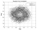
도 4 내지 도 8을 참조하면, 동작 시험 결과 스펙트럼 상에서 그림 6의 등화기 입력 신호의 스펙트럼은 다중경로 페이딩으로 인해 주파수 선택적 페이딩 스펙트럼 형태를 보이지만 등화기의 출력 신호는 다중경로 영향이 극복된 스펙트럼을 확인할 수 있다.Referring to FIGS. 4 to 8, the spectrum of the input signal of the equalizer of Figure 6 on the spectrum of the operation test results shows a frequency selective fading spectrum form due to multipath fading, but the output signal of the equalizer has a spectrum in which the multipath effect is overcome. You can check.
도 5에서는 등화기 입력 심볼에 비해 출력 심볼은 뚜렷한 QPSK 성상점을 확인할 수 있다. 해상 통신 환경에 대한 채널 모델에 대하여 VDE 물리계층의 BER 성능을 확인하고, 동일한 해상 채널에 대한 MX-S2X 물리계층의 성능 분석 및 설계의 타당성을 확인한다.In FIG. 5, it can be seen that the QPSK constellation point is clear in the output symbol compared to the equalizer input symbol. The BER performance of the VDE physical layer is verified for the channel model for the maritime communication environment, and the performance analysis and design validity of the MX-S2X physical layer for the same maritime channel are verified.
해상통신용 다중경로 페이딩 채널은 Delay & Power profile을 적용하였고 VDE와 MX-S2X는 운용 주파수가 각각 161.8375㎒와, 2.4㎓로 다름에 따라 적용되는 도플러 주파수는 각각 7.4925㎐와 111.11㎐를 적용하였다. 그리고 Rician K-factor는 LOS(Line-Of-Sight)가 보장되는 경우를 가정하여 14㏈(약 25.1)로 한다.Delay & power profile was applied to the multipath fading channel for maritime communication, and the operating frequencies of VDE and MX-S2X were 161.8375 MHz and 2.4 GHz, respectively, so the applied Doppler frequencies were 7.4925 Hz and 111.11 Hz, respectively. And the Rician K-factor is set to 14 dB (approximately 25.1) assuming that LOS (Line-Of-Sight) is guaranteed.
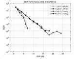
이하에서는, 다중경로 페이딩 채널 모델에 대한 VDE 100㎑ 대역폭 모드의 모의시험 결과와 실해역 시험 결과를 비교하여 Yang(2010)의 다중경로 페이딩 채널 모델에 대한 타당성을 확인한다. VDE 100㎑ 대역폭 모드에 대AWGN 및 Yang(2010) 의 다중경로 페이딩 채널 모델 하에서의 성능은 각각 도 6 및 도 7과 같다.In the following, the validity of the multipath fading channel model of Yang (2010) is verified by comparing the simulation test results of the
도 6은 Link ID 11 및 17로 π/4-QPSK 변조 및 Turbo 코드 부호율 1/2을 적용한 결과이고, 도 7는 Link ID 19로 16QAM 변조 및 Turbo 코드 3/4을 적용한 결과이다. 상기 결과 모두 BER=1×10⁻⁴ 기준으로 다중경로 페이딩 채널의 성능이 AWGN 성능 대비 약 8㏈ 정도 열화되며, 다중경로 페이딩 채널의 성능이 Error-floor 경향을 보이는 것을 확인할 수 있다.6 is a result of applying π/4-QPSK modulation and Turbo
이와 같은 Error-floor 경향은 실해역 시험에서 선박국 수신 SNR이 충분한 환경에서도 측정한 PSR(Packet Success Ratio)의 측정결과 에러가 발생됨을 확인할 수 있다.Such an error-floor tendency can confirm that an error occurs as a result of PSR (Packet Success Ratio) measured even in an environment where the received SNR of a ship station is sufficient in a real sea area test.
이러한 시험 결과는 다중경로에 의한 ISI 영향으로 볼 수 있으며, 그 효과는 주파수 영역에서 주파수 선택적 페이딩으로 나타나고 신호의 품질을 열화 시킨다. 신호 품질을 열화 시키는 정도는 Delay & Power profile이 대상 신호에 미치는 영향으로 판단할 수 있는데, 정량적으로 판단하기 쉬운 방법은 채널 모델에 정의한 최대 지연 시간이 심볼 단위 상에 미치는 영향으로 판단할 수 있다.These test results can be seen as the ISI effect caused by multipath, and the effect appears as frequency selective fading in the frequency domain and degrades the quality of the signal. The degree of signal quality deterioration can be judged by the effect of the Delay & Power profile on the target signal. An easy way to quantitatively determine is the effect of the maximum delay time defined in the channel model on a symbol unit.
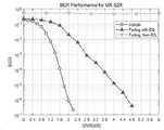
도 8은 MX-S2X 물리계층의 BER 성능을 분석한 결과이다. AWGN 채널에서는 SNR 1.6dB에서 BER 1×10⁻⁴의 성능을 보였으며, Yang(2010) 채널 모델에 대한 SNR상의 영향력을 확인하기 위해 그림4의 등화기를 거치지 않고 채널보상을 적용하지 않는 경우의 성능을 분석해 본 결과 BER은 약5×10⁻¹로 정상적인 통신 채널을 제공하지 못하는 것으로 확인되었다. MX-S2X 물리계층의 성능을 확인하기 위해 등화기에서 채널보상을 한 경우의 성능을 분석해 본 결과 SNR 3.5dB에서 BER 1×10⁻⁴의 성능을 보임으로, AWGN 대비 약 2dB 열화 범위 내에서 동작하는 것으로 확인되었다.8 is a result of analyzing the BER performance of the MX-S2X physical layer. The AWGN channel showed performance of
채널보상 기능을 미적용할 경우 MX-S2X의 symbol rate는 6.144㎒이므로 Yang(2010) 채널 모델의 최대 지연 2.2㎲는 MX-S2X 심볼 약 13.52 심볼에 해당한다. 이런 Delay Profile의 영향은 VDE 심볼 내에 다른 크기와 다른 위상으로 수신되는 간섭으로 작용하여 ISI 영향으로 인한 수신 신호 품질의 열화를 발생시킨다. MX-S2X에서의 최대 지연의 영향은 다른 크기와 다른 위상뿐만 아니라 다른 심볼 간 신호가 합산됨으로 인해 더욱 성능 열화에 큰 영향을 받는다.When the channel compensation function is not applied, the symbol rate of MX-S2X is 6.144 MHz, so the maximum delay of 2.2 μs in the channel model of Yang (2010) corresponds to about 13.52 symbols of the MX-S2X symbol. The effect of this Delay Profile acts as interference received with different magnitudes and different phases within the VDE symbol, resulting in deterioration of the received signal quality due to the ISI effect. The effect of the maximum delay in MX-S2X is greatly affected by performance degradation due to the addition of signals of different magnitudes and phases as well as different inter-symbols.
등화기를 적용한 경우 Error-floor가 나타나지 않았으며, 특히 SNR 2dB 열화 범위 내에서 동작하는 것으로 분석된 것은 등화기의 신호 추정 방법 및 보상 방법이 적합하고, 슬롯 구조상 충분한 Training sequence가 할당되었으며, 채널 추정의 정확도를 높이기 위한 파일럿의 배치와 Coherence time 내 슬롯이 전송되도록 설계한 것 모두 적합하다고 볼 수 있다. 다시 말해, SNR이 높음에도 불구하고 발생했던 Error-floor는 물리 계층의 적합한 설계로 개선된 것으로 판단된다.Error-floor did not appear when the equalizer was applied. In particular, it was analyzed that the signal estimation method and compensation method of the equalizer were suitable for operating within the SNR 2dB degradation range, a sufficient training sequence was allocated due to the slot structure, and channel estimation Both the arrangement of pilots to increase accuracy and the design so that slots within coherence time are transmitted can be considered appropriate. In other words, it is judged that the error-floor that occurred despite the high SNR was improved by the proper design of the physical layer.
한정된 실시예와 도면에 의해 설명되었으나, 본 발명은 상기의 실시예에 한정되는 것은 아니며, 이는 본 발명이 속하는 분야에서 통상의 지식을 가진 자라면 이러한 기재로부터 다양한 수정 및 변형이 가능하다. 따라서, 본 발명 사상은 아래에 기재된 특허청구범위에 의해서만 파악되어야 하고, 이의 균등 또는 등가적 변형 모두는 본 발명 사상의 범주에 속한다고 할 것이다.Although described by the limited embodiments and drawings, the present invention is not limited to the above embodiments, and those skilled in the art can make various modifications and variations from these descriptions. Therefore, the spirit of the present invention should be grasped only by the claims described below, and all equivalent or equivalent modifications thereof will be said to belong to the scope of the spirit of the present invention.
100: 데이터 송신 장치,
200: 데이터 수신 장치,100: data transmission device;
200: data receiving device;
Claims (2)
Translated fromKorean슬롯 시간에 따라 생성된 복수의 슬롯, 파일럿 전송 주기에 따라 상기 복수의 슬롯의 앞, 중간 및 뒤에 각각 배치된 채널 추정을 위한 복수의 파일럿 및 상기 복수의 파일럿 사이에 배치된 데이터 심볼로 구성된 전송 프레임을 링크 채널을 통해 데이터 수신 장치에 송신하는 데이터 송신 장치; 및
상기 데이터 송신 장치로부터 전송 프레임을 수신하면 상기 전송 프레임의 복수의 슬롯 각각에 대한 복수의 파일럿을 이용하여 주파수 영역에서 채널 추정후 선형 보간하여 상기 복수의 파일럿 사이에 있는 데이터에 대한 채널 보상을 실행하고, 상기 채널 보상된 신호를 다시 시간 영역 심볼로 변환하는 데이터 수신 장치를 포함하고,
상기 데이터 수신 장치는
상기 복수의 파일럿 중 제1 파일럿에 대해서 제1 파일럿으로부터 획득된 잡음 분산(σ1) 및 제1 파일럿으로부터 획득된 LS 연산 결과(H1)를 이용하여 주파수 영역에서 채널 추정후 선형 보간하고, 상기 복수의 파일럿 중 제2 파일럿에 대해서 제2 파일럿으로부터 획득된 잡음 분산(σ2) 및 제2 파일럿으로부터 획득된 LS 연산 결과(H2)를 이용하여 주파수 영역에서 채널 추정후 선형 보간하고, 상기 복수의 파일럿 중 제3 파일럿에 대해서 상기 제3 파일럿으로부터 획득된 잡음 분산(σ3) 및 상기 제3 파일럿으로부터 획득된 LS 연산 결과(H3)를 이용하여 주파수 영역에서 채널 추정후 선형 보간하고,
상기 제1 파일럿이 수신된 후 제2 파일럿이 수신될 때까지의 선형 보간 결과(H12)는 상기 제1 파일럿으로부터 획득된 LS 연산 결과(H1), 제2 파일럿으로부터 획득된 LS 연산 결과(H2), 제1 파일럿 및 제2 파일럿 사이의 데이터 심볼 개수 +1(C)를 이용하여 산출되고,
상기 제2 파일럿 및 제3 파일럿 사이의 선형 보간 결과(H23)는 상기 제2 파일럿으로부터 획득된 LS 연산 결과(H2), 제3 파일럿으로부터 획득된 LS 연산 결과(H3), 제2 파일럿 및 제3 v파일럿 사이의 데이터 심볼 개수 +1(C)를 이용하여 산출되고,
상기 제1 파일럿 및 상기 제2 파일럿 사이의 잡음 분산(σ12)은 상기 제1 파일럿으로부터 획득된 잡음 분산(σ1), 상기 제2 파일럿으로부터 획득된 잡음 분산(σ2), 상기 제1 파일럿 및 상기 제2 파일럿 사이의 데이터 심볼 개수 +1(C)를 이용하여 산출되고,
상기 제2 파일럿 및 상기 제3 파일럿 사이의 잡음 분산(σ23)은 제2 파일럿으로부터 획득된 잡음 분산(σ2), 제3 파일럿으로부터 획득된 잡음 분산(σ3), 제2 파일럿 및 제3 파일럿 사이의 데이터 심볼 개수 +1(C)를 이용하여 산출되는 것을 특징으로 하는 것을 특징으로 하는
선박 중심 직접 통신 시스템.
In a ship-centered direct communication system including a data transmission device and a data reception device,
A transmission frame composed of a plurality of slots generated according to the slot time, a plurality of pilots for channel estimation disposed before, in the middle, and behind the plurality of slots according to the pilot transmission period, and data symbols disposed between the plurality of pilots. a data transmission device for transmitting to a data reception device through a link channel; and
When a transmission frame is received from the data transmission apparatus, channel estimation is performed in the frequency domain using a plurality of pilots for each of a plurality of slots of the transmission frame, followed by linear interpolation to perform channel compensation for data between the plurality of pilots, , a data receiving device for converting the channel compensated signal back into a time domain symbol,
The data receiving device
For the first pilot among the plurality of pilots, linear interpolation is performed after channel estimation in the frequency domain using the noise variance (σ1) obtained from the first pilot and the LS operation result (H1) obtained from the first pilot, and For the second pilot among the pilots, linear interpolation is performed after channel estimation in the frequency domain using the noise variance (σ2) obtained from the second pilot and the LS operation result (H2) obtained from the second pilot, and For the 3 pilots, linear interpolation is performed after channel estimation in the frequency domain using the noise variance (σ3) obtained from the third pilot and the LS operation result (H3) obtained from the third pilot;
The linear interpolation result (H12 ) from when the first pilot is received until the second pilot is received is the LS operation result (H1) obtained from the first pilot and the LS operation result (H2) obtained from the second pilot ), calculated using the number of data symbols between the first pilot and the second pilot + 1 (C),
The linear interpolation result between the second pilot and the third pilot (H23 ) is the LS operation result obtained from the second pilot (H2 ), the LS operation result obtained from the third pilot (H3 ), and the second pilot And it is calculated using the number of data symbols + 1 (C) between the third v pilots,
The noise variance (σ12 ) between the first pilot and the second pilot is the noise variance (σ1) obtained from the first pilot, the noise variance (σ2) obtained from the second pilot, the first pilot and the noise variance (σ2) obtained from the second pilot. It is calculated using the number of data symbols between the second pilots +1 (C),
The noise variance (σ23 ) between the second pilot and the third pilot is the noise variance obtained from the second pilot (σ2 ), the noise variance obtained from the third pilot (σ3 ), the second pilot and the third pilot. Characterized in that it is calculated using the number of data symbols between pilots + 1 (C)
Ship-centric direct communication system.
상기 데이터 수신 장치가 상기 전송 프레임을 수신하면 상기 전송 프레임의 복수의 슬롯 각각에 대한 복수의 파일럿을 이용하여 주파수 영역에서 채널 추정후 선형 보간하여 상기 복수의 파일럿 사이에 있는 데이터에 대한 채널 보상을 실행하는 단계; 및
상기 데이터 수신 장치가 상기 채널 보상된 신호를 다시 시간 영역 심볼로 변환하는 단계를 포함하고,
상기 주파수 영역에서 채널 추정후 선형 보간하여 상기 복수의 파일럿 사이에 있는 데이터에 대한 채널 보상을 실행하는 단계는
상기 복수의 파일럿 중 제1 파일럿에 대해서 제1 파일럿으로부터 획득된 잡음 분산(σ1) 및 제1 파일럿으로부터 획득된 LS 연산 결과(H1)를 이용하여 주파수 영역에서 채널 추정후 선형 보간하는 단계;
상기 복수의 파일럿 중 제2 파일럿에 대해서 제2 파일럿으로부터 획득된 잡음 분산(σ2) 및 제2 파일럿으로부터 획득된 LS 연산 결과(H2)를 이용하여 주파수 영역에서 채널 추정후 선형 보간하는 단계; 및
상기 복수의 파일럿 중 제3 파일럿에 대해서 상기 제3 파일럿으로부터 획득된 잡음 분산(σ3) 및 상기 제3 파일럿으로부터 획득된 LS 연산 결과(H3)를 이용하여 주파수 영역에서 채널 추정후 선형 보간하는 단계를 포함하고,
상기 제1 파일럿 및 상기 제2 파일럿 사이의 선형 보간 결과(H12)는
상기 제1 파일럿으로부터 획득된 LS 연산 결과(H1), 제2 파일럿으로부터 획득된 LS 연산 결과(H2), 제1 파일럿 및 제2 파일럿 사이의 데이터 심볼 개수 +1(C)를 이용하여 산출되고,
상기 제2 파일럿 및 제3 파일럿 사이의 선형 보간 결과(H23)는
상기 제2 파일럿으로부터 획득된 LS 연산 결과(H2), 파일럿 #3로부터 획득된 LS 연산 결과(H3), 파일럿 #2 및 파일럿 #3 사이의 데이터 심볼 개수 +1(C)를 이용하여 산출되고,
상기 제1 파일럿 및 상기 제2 파일럿 사이의 잡음 분산(σ12)은
상기 제1 파일럿으로부터 획득된 잡음 분산(σ1), 상기 제2 파일럿으로부터 획득된 잡음 분산(σ2), 상기 제1 파일럿 및 상기 제2 파일럿 사이의 데이터 심볼 개수 +1(C)를 이용하여 산출되고,
상기 제2 파일럿 및 상기 제3 파일럿 사이의 잡음 분산(σ23)은
제2 파일럿으로부터 획득된 잡음 분산(σ2), 제3 파일럿으로부터 획득된 잡음 분산(σ3), 제2 파일럿 및 제3 파일럿 사이의 데이터 심볼 개수 +1(C)를 이용하여 산출하는 것을 특징으로 하는
선박 중심 직접 통신 시스템의 실행 방법.A plurality of slots generated by the data transmission apparatus according to the slot time, a plurality of pilots for channel estimation arranged before, in the middle, and behind the plurality of slots according to the pilot transmission period, respectively, and data symbols arranged between the plurality of pilots Transmitting a transmission frame composed of to a data receiving apparatus through a link channel;
When the data receiving apparatus receives the transmission frame, channel estimation is performed in the frequency domain using a plurality of pilots for each of a plurality of slots of the transmission frame, followed by linear interpolation to perform channel compensation for data between the plurality of pilots. doing; and
Converting, by the data receiving apparatus, the channel-compensated signal back to a time domain symbol;
Performing channel compensation for data between the plurality of pilots by performing linear interpolation after channel estimation in the frequency domain
performing linear interpolation after estimating a channel in a frequency domain using a noise variance (σ1) obtained from a first pilot among the plurality of pilots and a LS operation result (H1) obtained from the first pilot;
performing linear interpolation after estimating a channel in a frequency domain using a noise variance (σ2) obtained from a second pilot among the plurality of pilots and a LS operation result (H2) obtained from the second pilot; and
Linear interpolation after channel estimation in the frequency domain using the noise variance (σ3 ) obtained from the third pilot and the LS operation result (H3 ) obtained from the third pilot among the plurality of pilots contains steps,
The linear interpolation result (H12 ) between the first pilot and the second pilot is
Calculated using the LS operation result (H1) obtained from the first pilot, the LS operation result (H2) obtained from the second pilot, and the number of data symbols between the first pilot and the second pilot +1 (C),
The linear interpolation result (H23 ) between the second pilot and the third pilot is
Calculated using the LS calculation result (H2 ) obtained from the second pilot, the LS calculation result (H3) obtained from pilot #3, and the number of data symbols between pilots #2 and #3 +1 (C) ,
The noise variance (σ12 ) between the first pilot and the second pilot is
Calculated using noise variance (σ1) obtained from the first pilot, noise variance (σ2) obtained from the second pilot, and the number of data symbols between the first pilot and the second pilot +1 (C) ,
The noise variance (σ23 ) between the second pilot and the third pilot is
It is characterized in that it is calculated using the noise variance (σ2 ) obtained from the second pilot, the noise variance (σ3 ) obtained from the third pilot, and the number of data symbols between the second and third pilots +1 (C) to be
Implementation method of ship-centric direct communication system.
Priority Applications (3)
| Application Number | Priority Date | Filing Date | Title |
|---|---|---|---|
| KR1020220139500AKR102487892B1 (en) | 2022-10-26 | 2022-10-26 | Ship centric direct communication and method of performing thereof |
| US18/493,183US20240147522A1 (en) | 2022-10-26 | 2023-10-24 | Ship-centric direct communication system and operation method thereof |
| EP23205454.4AEP4362405A1 (en) | 2022-10-26 | 2023-10-24 | Ship-centric direct communication system and operation method thereof |
Applications Claiming Priority (1)
| Application Number | Priority Date | Filing Date | Title |
|---|---|---|---|
| KR1020220139500AKR102487892B1 (en) | 2022-10-26 | 2022-10-26 | Ship centric direct communication and method of performing thereof |
Publications (1)
| Publication Number | Publication Date |
|---|---|
| KR102487892B1true KR102487892B1 (en) | 2023-01-12 |
Family
ID=84923524
Family Applications (1)
| Application Number | Title | Priority Date | Filing Date |
|---|---|---|---|
| KR1020220139500AActiveKR102487892B1 (en) | 2022-10-26 | 2022-10-26 | Ship centric direct communication and method of performing thereof |
Country Status (3)
| Country | Link |
|---|---|
| US (1) | US20240147522A1 (en) |
| EP (1) | EP4362405A1 (en) |
| KR (1) | KR102487892B1 (en) |
Citations (5)
| Publication number | Priority date | Publication date | Assignee | Title |
|---|---|---|---|---|
| KR100989098B1 (en) | 2010-04-19 | 2010-10-25 | 엘아이지넥스원 주식회사 | Data frame generation method based on gmsk modulation for sc-fde system |
| KR101275852B1 (en) | 2012-03-27 | 2013-06-17 | 연세대학교 산학협력단 | Method and apparatus for transmitting/receiving data based on sc-fde using uw |
| JP2016116205A (en)* | 2014-12-18 | 2016-06-23 | 富士通株式会社 | Positional information management unit, mobile apparatus and radio communication system |
| KR101858993B1 (en) | 2018-02-12 | 2018-05-17 | 국방과학연구소 | Method of reducing pilot overhead in SC-FDE transmission structure |
| KR20220111381A (en) | 2021-02-02 | 2022-08-09 | 한국전자통신연구원 | Transceiving method for phase noise compensation in SC-FDE scheme, and apparatus therefor |
Family Cites Families (7)
| Publication number | Priority date | Publication date | Assignee | Title |
|---|---|---|---|---|
| EP1720277B1 (en)* | 2000-07-05 | 2017-09-27 | Sony Deutschland Gmbh | Pilot pattern design for multiple antennas in an OFDM system |
| KR101225171B1 (en)* | 2003-08-12 | 2013-01-22 | 파나소닉 주식회사 | Radio communication apparatus and pilot symbol transmission method |
| CN1253029C (en)* | 2003-09-02 | 2006-04-19 | 东南大学 | Method for channel evaluation using circular orthogonal pilot frequency sequence |
| JP4093581B2 (en)* | 2004-09-24 | 2008-06-04 | 株式会社東芝 | Wireless receiver |
| US7693231B2 (en)* | 2006-05-15 | 2010-04-06 | Qualcomm Incorporated | System and method of calculating noise variance |
| MX393505B (en)* | 2016-07-28 | 2025-03-24 | Guangdong Oppo Mobile Telecommunications Corp Ltd | PILOT SIGNAL TRANSMISSION METHOD, TERMINAL EQUIPMENT AND NETWORK EQUIPMENT |
| CN114070538B (en)* | 2021-11-03 | 2025-04-25 | 葳迪易(苏州)信息科技有限公司 | A dynamic pilot allocation method in ship-to-shore VDE communication |
- 2022
- 2022-10-26KRKR1020220139500Apatent/KR102487892B1/enactiveActive
- 2023
- 2023-10-24EPEP23205454.4Apatent/EP4362405A1/enactivePending
- 2023-10-24USUS18/493,183patent/US20240147522A1/enactivePending
Patent Citations (5)
| Publication number | Priority date | Publication date | Assignee | Title |
|---|---|---|---|---|
| KR100989098B1 (en) | 2010-04-19 | 2010-10-25 | 엘아이지넥스원 주식회사 | Data frame generation method based on gmsk modulation for sc-fde system |
| KR101275852B1 (en) | 2012-03-27 | 2013-06-17 | 연세대학교 산학협력단 | Method and apparatus for transmitting/receiving data based on sc-fde using uw |
| JP2016116205A (en)* | 2014-12-18 | 2016-06-23 | 富士通株式会社 | Positional information management unit, mobile apparatus and radio communication system |
| KR101858993B1 (en) | 2018-02-12 | 2018-05-17 | 국방과학연구소 | Method of reducing pilot overhead in SC-FDE transmission structure |
| KR20220111381A (en) | 2021-02-02 | 2022-08-09 | 한국전자통신연구원 | Transceiving method for phase noise compensation in SC-FDE scheme, and apparatus therefor |
Also Published As
| Publication number | Publication date |
|---|---|
| EP4362405A1 (en) | 2024-05-01 |
| US20240147522A1 (en) | 2024-05-02 |
Similar Documents
| Publication | Publication Date | Title |
|---|---|---|
| KR101564479B1 (en) | Method and system for reduced complexity channel estimation and interference cancellation for v-mimo demodulation | |
| US9960887B2 (en) | Method and apparatus of signal transmission and reception in a filter bank multiple carrier system | |
| JP5539362B2 (en) | PUCCH spatial code transmission diversity method and system | |
| JP5579182B2 (en) | Enabling downlink transparent relay in wireless communication networks | |
| KR101002839B1 (en) | Relay station apparatus and method for interference cancellation in a communication system | |
| US8000405B2 (en) | Transmission method, transmission apparatus and communication system | |
| US20170310509A1 (en) | Method and apparatus for signal detection in a wireless communication system | |
| US20120155411A1 (en) | Process for inter-cell interference cancellation in a synchronized ofdm system, and apparatus for the same | |
| JP2006186732A (en) | Radio communications device and radio communication method | |
| US20090290616A1 (en) | Method and apparatus for determining the spatial channels in an spatial division multiple access (sdma)-based wireless communication system | |
| US20110107174A1 (en) | Method and apparatus for interchanging multipath signals in a sc-fdma system | |
| WO2015129873A1 (en) | Wireless base station, user terminal, wireless communication method and wireless communication system | |
| WO2015129874A1 (en) | Wireless base station, user terminal, wireless communication method and wireless communication system | |
| US7860176B2 (en) | OFDM system with reverse link interference estimation | |
| JP2004120730A (en) | Communication method and transmitting device and receiving device using the same | |
| US9531493B2 (en) | Receiving apparatus, method for receiving, transmitting apparatus, method for transmitting, and wireless communication system | |
| Moriyama et al. | Experimental evaluation of a novel up-link NOMA system for IoT communication equipping repetition transmission and receive diversity | |
| KR20070074708A (en) | Apparatus and Method for Channel State Estimation in Wireless Communication Systems | |
| KR102487892B1 (en) | Ship centric direct communication and method of performing thereof | |
| CN108400947A (en) | Interference noise covariance matrix estimation method, apparatus and system | |
| US20100167773A1 (en) | Mobile Station And Radio Base Station | |
| Takahashi et al. | Ambient OFDM pilot-aided delay-shift keying and its efficient detection for ultra low-power communications | |
| CN113852930B (en) | 5G communication system, method, electronic equipment and medium for railway train | |
| Choi et al. | Development of millimeter-wave communication modem for mobile wireless backhaul in mobile hotspot network | |
| Jang et al. | Low-Complexity Equalization of 3GPP High-Speed Train Channel |
Legal Events
| Date | Code | Title | Description |
|---|---|---|---|
| PA0109 | Patent application | Patent event code:PA01091R01D Comment text:Patent Application Patent event date:20221026 | |
| PA0201 | Request for examination | ||
| PA0302 | Request for accelerated examination | Patent event date:20221026 Patent event code:PA03022R01D Comment text:Request for Accelerated Examination | |
| N231 | Notification of change of applicant | ||
| PN2301 | Change of applicant | Patent event date:20221123 Comment text:Notification of Change of Applicant Patent event code:PN23011R01D | |
| E902 | Notification of reason for refusal | ||
| PE0902 | Notice of grounds for rejection | Comment text:Notification of reason for refusal Patent event date:20221205 Patent event code:PE09021S01D | |
| E701 | Decision to grant or registration of patent right | ||
| PE0701 | Decision of registration | Patent event code:PE07011S01D Comment text:Decision to Grant Registration Patent event date:20230106 | |
| GRNT | Written decision to grant | ||
| PR0701 | Registration of establishment | Comment text:Registration of Establishment Patent event date:20230109 Patent event code:PR07011E01D | |
| PR1002 | Payment of registration fee | Payment date:20230109 End annual number:3 Start annual number:1 | |
| PG1601 | Publication of registration |