KR102487273B1 - Gas pressure detection device, robot equipped with gas pressure detection device, and gas pressure detection method thereof - Google Patents
Gas pressure detection device, robot equipped with gas pressure detection device, and gas pressure detection method thereofDownload PDFInfo
- Publication number
- KR102487273B1 KR102487273B1KR1020217018563AKR20217018563AKR102487273B1KR 102487273 B1KR102487273 B1KR 102487273B1KR 1020217018563 AKR1020217018563 AKR 1020217018563AKR 20217018563 AKR20217018563 AKR 20217018563AKR 102487273 B1KR102487273 B1KR 102487273B1
- Authority
- KR
- South Korea
- Prior art keywords
- pressure
- gas
- arm
- detection device
- measured
- Prior art date
- Legal status (The legal status is an assumption and is not a legal conclusion. Google has not performed a legal analysis and makes no representation as to the accuracy of the status listed.)
- Active
Links
Images


Classifications
- G—PHYSICS
- G01—MEASURING; TESTING
- G01L—MEASURING FORCE, STRESS, TORQUE, WORK, MECHANICAL POWER, MECHANICAL EFFICIENCY, OR FLUID PRESSURE
- G01L7/00—Measuring the steady or quasi-steady pressure of a fluid or a fluent solid material by mechanical or fluid pressure-sensitive elements
- G01L7/16—Measuring the steady or quasi-steady pressure of a fluid or a fluent solid material by mechanical or fluid pressure-sensitive elements in the form of pistons
- B—PERFORMING OPERATIONS; TRANSPORTING
- B25—HAND TOOLS; PORTABLE POWER-DRIVEN TOOLS; MANIPULATORS
- B25J—MANIPULATORS; CHAMBERS PROVIDED WITH MANIPULATION DEVICES
- B25J13/00—Controls for manipulators
- B25J13/08—Controls for manipulators by means of sensing devices, e.g. viewing or touching devices
- B25J13/087—Controls for manipulators by means of sensing devices, e.g. viewing or touching devices for sensing other physical parameters, e.g. electrical or chemical properties
- B—PERFORMING OPERATIONS; TRANSPORTING
- B25—HAND TOOLS; PORTABLE POWER-DRIVEN TOOLS; MANIPULATORS
- B25J—MANIPULATORS; CHAMBERS PROVIDED WITH MANIPULATION DEVICES
- B25J19/00—Accessories fitted to manipulators, e.g. for monitoring, for viewing; Safety devices combined with or specially adapted for use in connection with manipulators
- B25J19/0008—Balancing devices
- B25J19/0012—Balancing devices using fluidic devices
- B—PERFORMING OPERATIONS; TRANSPORTING
- B25—HAND TOOLS; PORTABLE POWER-DRIVEN TOOLS; MANIPULATORS
- B25J—MANIPULATORS; CHAMBERS PROVIDED WITH MANIPULATION DEVICES
- B25J19/00—Accessories fitted to manipulators, e.g. for monitoring, for viewing; Safety devices combined with or specially adapted for use in connection with manipulators
- B25J19/0066—Means or methods for maintaining or repairing manipulators
- B—PERFORMING OPERATIONS; TRANSPORTING
- B25—HAND TOOLS; PORTABLE POWER-DRIVEN TOOLS; MANIPULATORS
- B25J—MANIPULATORS; CHAMBERS PROVIDED WITH MANIPULATION DEVICES
- B25J19/00—Accessories fitted to manipulators, e.g. for monitoring, for viewing; Safety devices combined with or specially adapted for use in connection with manipulators
- B25J19/02—Sensing devices
- B—PERFORMING OPERATIONS; TRANSPORTING
- B25—HAND TOOLS; PORTABLE POWER-DRIVEN TOOLS; MANIPULATORS
- B25J—MANIPULATORS; CHAMBERS PROVIDED WITH MANIPULATION DEVICES
- B25J19/00—Accessories fitted to manipulators, e.g. for monitoring, for viewing; Safety devices combined with or specially adapted for use in connection with manipulators
- B25J19/06—Safety devices
- B—PERFORMING OPERATIONS; TRANSPORTING
- B25—HAND TOOLS; PORTABLE POWER-DRIVEN TOOLS; MANIPULATORS
- B25J—MANIPULATORS; CHAMBERS PROVIDED WITH MANIPULATION DEVICES
- B25J9/00—Programme-controlled manipulators
- B25J9/10—Programme-controlled manipulators characterised by positioning means for manipulator elements
- B25J9/14—Programme-controlled manipulators characterised by positioning means for manipulator elements fluid
- B25J9/144—Linear actuators
- B—PERFORMING OPERATIONS; TRANSPORTING
- B25—HAND TOOLS; PORTABLE POWER-DRIVEN TOOLS; MANIPULATORS
- B25J—MANIPULATORS; CHAMBERS PROVIDED WITH MANIPULATION DEVICES
- B25J9/00—Programme-controlled manipulators
- B25J9/16—Programme controls
- B25J9/1656—Programme controls characterised by programming, planning systems for manipulators
- B25J9/1664—Programme controls characterised by programming, planning systems for manipulators characterised by motion, path, trajectory planning
- G—PHYSICS
- G01—MEASURING; TESTING
- G01L—MEASURING FORCE, STRESS, TORQUE, WORK, MECHANICAL POWER, MECHANICAL EFFICIENCY, OR FLUID PRESSURE
- G01L19/00—Details of, or accessories for, apparatus for measuring steady or quasi-steady pressure of a fluent medium insofar as such details or accessories are not special to particular types of pressure gauges
- G01L19/08—Means for indicating or recording, e.g. for remote indication
- G01L19/083—Means for indicating or recording, e.g. for remote indication electrical
Landscapes
- Engineering & Computer Science (AREA)
- Robotics (AREA)
- Mechanical Engineering (AREA)
- Physics & Mathematics (AREA)
- General Physics & Mathematics (AREA)
- Human Computer Interaction (AREA)
- Manipulator (AREA)
- Measuring Fluid Pressure (AREA)
Abstract
Translated fromKorean
Description
Translated fromKorean본 발명은 가스 밸런서(balancer)의 가스의 압력을 검출하는 가스압 검지(檢知) 장치와, 이러한 가스압 검지 장치를 구비하는 로봇과, 이러한 가스압 검지 장치를 이용한 가스압 검지 방법에 관한 것이다.The present invention relates to a gas pressure detection device for detecting the gas pressure of a gas balancer, a robot equipped with such a gas pressure detection device, and a gas pressure detection method using such a gas pressure detection device.
일본 특허 제5512706호 공보에는, 암과, 이러한 암에 회동 가능하게 연결되는 회동 암과, 이러한 회동 암의 회동 부하를 경감하는 가스 밸런서로서의 기체 스프링을 구비하는 로봇이 개시되어 있다. 이러한 로봇에서는, 가스 밸런서의 압력이 검출된다. 이러한 압력이 소정의 압력 값에서 벗어나면 압력이 조정된다. 이에 따라서, 이러한 로봇에서는, 이러한 가스 밸런서의 메인터넌스(maintenance)가 경감되고 있다.Japanese Patent No. 5512706 discloses a robot including an arm, a rotational arm rotatably connected to the arm, and a gas spring as a gas balancer that reduces a rotational load of the rotational arm. In this robot, the pressure of the gas balancer is detected. If this pressure deviates from the predetermined pressure value, the pressure is adjusted. Accordingly, in such a robot, maintenance of such a gas balancer is reduced.
이러한 가스 밸런서에는, 이러한 로봇의 가동 가능한 압력으로서, 소정의 압력 값이 설정되어 있다. 이러한 소정의 압력 값과 실제의 측정 압력의 대소 관계로부터, 가스 밸런서의 압력의 저하를 검지하고 있다. 그러나, 실제로는, 가스 밸런서의 압력이 그다지 저하되지 않았음에도 불구하고, 이러한 소정의 압력 값과 측정 압력에 큰 차이가 검출될 수가 있다. 이러한 압력의 저하의 오(誤) 검지는, 불필요한 로봇의 정지나 가스 밸런서의 점검을 야기한다. 이러한 압력의 저하의 오 검지는 이러한 로봇의 생산성을 저해한다.In this gas balancer, a predetermined pressure value is set as the movable pressure of this robot. A decrease in the pressure of the gas balancer is detected from the magnitude relationship between the predetermined pressure value and the actual measured pressure. However, in practice, a large difference between this predetermined pressure value and the measured pressure can be detected even though the pressure of the gas balancer has not decreased so much. Such erroneous detection of a drop in pressure causes an unnecessary stop of the robot or inspection of the gas balancer. Misdetection of this drop in pressure hinders the productivity of these robots.
본 발명의 목적은, 가스 밸런서에서, 가스 압력의 저하의 오 검지를 저감하는 가스압 검지 장치와, 이러한 가스압 검지 장치를 구비하는 로봇과, 이러한 가스압 검지 장치를 이용한 가스의 압력 저하의 검지 방법의 제공에 있다.An object of the present invention is to provide a gas pressure detection device for reducing false detection of a decrease in gas pressure in a gas balancer, a robot equipped with such a gas pressure detection device, and a method for detecting a decrease in gas pressure using such a gas pressure detection device is in
본 발명에 따른 가스압 검지 장치는, 암 지지부와, 상기 암 지지부에 회동 가능하게 지지되는 회동 암과, 상기 회동 암의 회전 부하를 경감하는 가스 밸런서와, 상기 가스 밸런서의 가스의 압력을 측정하는 압력 센서를 구비하는 로봇에서, 상기 압력의 저하를 검지한다. 이러한 가스 검지 장치는, 상기 회동 암의 회동 각도(θ)에서 기준 압력 Pa(θ)와 상기 회동 각도(θ)에서 상기 압력 센서가 측정하여 얻은 측정 압력 Pt(θ)의 대소 관계를 나타내는 변수 Rt(θ)를 산출하고, 측정 시각이 다른 복수의 상기 측정 압력 Pt(θ)로부터 복수의 상기 변수 Rt(θ)를 산출하고, 상기 측정 압력 Pt(θ)의 j 번째(j는 2 이상의 자연수)의 측정 시각(tj)에서 상기 변수 Rt(θ)의 이동 평균 Rtj(θ)를 산출하는 산출부와, 상기 이동 평균 Rtj(θ)와 기준 값(R)을 비교하여 상기 가스의 압력 저하를 검지하는 판정부를 구비한다.A gas pressure detection device according to the present invention comprises: an arm support, a rotational arm rotatably supported by the arm support, a gas balancer for reducing a rotational load of the rotational arm, and a pressure for measuring the gas pressure of the gas balancer. A robot equipped with a sensor detects the drop in pressure. This gas detection device is a variable Rt representing a magnitude relation between a reference pressure Pa (θ) at a rotation angle (θ) of the rotation arm and a measured pressure Pt (θ) obtained by measuring the pressure sensor at the rotation angle (θ). (θ) is calculated, and a plurality of variables Rt(θ) are calculated from a plurality of the measured pressures Pt(θ) at different measurement times, and the jth of the measured pressure Pt(θ) (j is a natural number of 2 or more). A calculator that calculates the moving average Rtj(θ) of the variable Rt(θ) at the measurement time point tj of , and detects a drop in pressure of the gas by comparing the moving average Rtj(θ) with a reference value R. It is provided with a judgment unit that
바람직하게는, 이러한 가스압 검지 장치에서는, 상기 산출부에서 산출하는 상기 변수 Rt(θ)가 상기 기준 압력 Pa(θ)와 상기 측정 압력 Pt(θ)로부터 계수 A로 하여 하기의 수식 (1)로 표시된다.Preferably, in such a gas pressure detection device, the variable Rt(θ) calculated by the calculation unit is expressed as the following formula (1) by taking a coefficient A from the reference pressure Pa(θ) and the measured pressure Pt(θ) displayed
[수 1][number 1]

바람직하게는, 이러한 가스압 검지 장치에서는, 상기 산출부가 산출하는 상기 이동 평균 Rtj(θ)가 i 번째(i는 1 이상의 자연수)의 측정 시각(ti)에서 j 번째(j는 i보다 큰 자연수)의 측정 시각(tj)까지 얻어지는 복수의 상기 변수 Rt(θ)를 이용하여 하기의 수식 (2)로 표시된다.Preferably, in such a gas pressure detection device, the moving average Rtj(θ) calculated by the calculating unit is measured from the i-th measurement time ti (i is a natural number greater than or equal to 1) to the j-th (j is a natural number greater than i). It is represented by the following formula (2) using a plurality of the above variables Rt(θ) obtained by the measurement time point tj.
[수 2][number 2]

바람직하게는, 상기 산출부가 상기 이동 평균 Rtj(θ)의 산출에 이용하는 복수의 상기 측정 압력 Pt(θ)의 측정 시각의 간격이 1 초 이하이다.Preferably, an interval of measurement time of a plurality of the measured pressures Pt(θ) used by the calculator to calculate the moving average Rtj(θ) is 1 second or less.
바람직하게는, 상기 산출부가 상기 이동 평균 Rtj(θ)의 산출에 이용하는 복수의 상기 측정 압력 Pt(θ)를 얻는 측정 시간이 10 초 이상이다.Preferably, the measurement time for obtaining a plurality of the measured pressures Pt(θ) used by the calculator to calculate the moving average Rtj(θ) is 10 seconds or longer.
바람직하게는, 상기 산출부가 상기 이동 평균 Rtj(θ)의 산출에 이용하는 복수의 상기 측정 압력 Pt(θ)를 얻는 측정 시간이 600 초 이하이다.Preferably, a measurement time for obtaining a plurality of the measured pressures Pt(θ) used by the calculator to calculate the moving average Rtj(θ) is 600 seconds or less.
본 발명에 따른 로봇은, 암 지지부와, 상기 암 지지부에 회동 가능하게 지지되는 회동 암과, 상기 회동 암의 회전 부하를 경감하는 가스 밸런서와, 상기 가스 밸런서의 가스의 압력을 측정하는 압력 센서와, 상기 압력의 저하를 검지하는 가스압 검지 장치를 구비한다. 상기 가스압 검지 장치는, 상기 회동 암의 회동 각도(θ)에서 기준 압력 Pa(θ)와 상기 회동 각도(θ)에서 상기 압력 센서가 측정하여 얻은 측정 압력 Pt(θ)의 대소 관계를 나타내는 변수 Rt(θ)를 산출하고, 측정 시각이 다른 복수의 상기 측정 압력 Pt(θ)로부터 복수의 상기 변수 Rt(θ)를 산출하고, 상기 측정 압력 Pt(θ)의 j 번째(j는 2 이상의 자연수)의 측정 시각(tj)에서 상기 변수 Rt(θ)의 이동 평균 Rtj(θ)를 산출하는 산출부와, 상기 이동 평균 Rtj(θ)와 기준 값(R)을 비교하여 상기 가스의 압력 저하를 검지하는 판정부를 구비한다.A robot according to the present invention includes an arm support, a rotational arm rotatably supported by the arm support, a gas balancer for reducing a rotational load of the rotational arm, a pressure sensor for measuring a gas pressure of the gas balancer, and , a gas pressure detection device for detecting a drop in the pressure. The gas pressure detection device is a variable Rt representing a magnitude relationship between a reference pressure Pa(θ) at a rotation angle θ of the rotation arm and a measured pressure Pt(θ) obtained by measuring the pressure sensor at the rotation angle θ. (θ) is calculated, and a plurality of variables Rt(θ) are calculated from a plurality of the measured pressures Pt(θ) at different measurement times, and the jth of the measured pressure Pt(θ) (j is a natural number of 2 or more). A calculator that calculates the moving average Rtj(θ) of the variable Rt(θ) at the measurement time point tj of , and detects a drop in pressure of the gas by comparing the moving average Rtj(θ) with a reference value R. It is provided with a judgment unit that
본 발명에 따른 가스압 검지 방법은, 암 지지부와, 상기 암 지지부에 회동 가능하게 지지되는 회동 암과, 상기 회동 암의 회전 부하를 경감하는 가스 밸런서와, 상기 가스 밸런서의 가스의 압력을 측정하는 압력 센서를 구비하는 로봇에서, 상기 가스 밸런서의 가스의 압력 저하를 검지한다. 이러한 가스 검지 방법은,A gas pressure detection method according to the present invention includes an arm support, a pivoting arm rotatably supported by the arm support, a gas balancer for reducing a rotational load of the pivoting arm, and a pressure for measuring the gas pressure of the gas balancer. A robot equipped with a sensor detects a drop in gas pressure in the gas balancer. This gas detection method,
(A) 상기 압력 센서로 상기 가스 밸런서의 가스의 압력을 측정하여 상기 회동 암의 회동 각도(θ)에서 측정 압력 Pt(θ)를 얻는 스텝,(A) measuring the gas pressure of the gas balancer with the pressure sensor to obtain a measured pressure Pt (θ) at a rotation angle (θ) of the rotation arm;
(B) 상기 측정 압력 Pt(θ)와 상기 회동 암의 회동 각도(θ)에서 기준 압력 Pa(θ)의 대소 관계를 나타내는 변수 Rt(θ)를 산출하는 스텝,(B) calculating a variable Rt(θ) representing a magnitude relationship between the measured pressure Pt(θ) and the reference pressure Pa(θ) at the rotation angle θ of the rotation arm;
(C) 측정 시각이 다른 복수의 상기 측정 압력 Pt(θ)로부터 복수의 상기 변수 Rt(θ)를 산출하고, 상기 측정 압력 Pt(θ)의 j 번째(j는 2 이상의 자연수)의 측정 시각(tj)에서 상기 변수 Rt(θ)의 이동 평균 Rtj(θ)를 산출하는 스텝, 및(C) A plurality of variables Rt(θ) are calculated from a plurality of measured pressures Pt(θ) at different measurement times, and the measurement time of the jth (j is a natural number of 2 or more) of the measured pressure Pt(θ) ( calculating a moving average Rtj(θ) of the variable Rt(θ) at tj), and
(D) 상기 이동 평균 Rtj(θ)와 기준 값(R)을 비교하여 상기 가스의 압력 저하를 검지하는 스텝을 포함한다.(D) comparing the moving average Rtj(θ) with a reference value R to detect a drop in pressure of the gas;
본 발명에 따른 가스압 검지 장치는, 기준 압력 Pa(θ)와 측정 압력 Pt(θ)의 대소 관계를 나타내는 변수 Rt(θ)를 산출하고, 변수 Rt(θ)의 이동 평균 Rtj(θ)를 산출한다. 이에 따라서, 이러한 가스압 검지 장치는, 일시적인 가스 밸런서의 압력 저하에 의한 오 검출이 저감된다. 이러한 가스압 검지 장치는 로봇의 생산성의 향상에 기여한다.The gas pressure detection device according to the present invention calculates the variable Rt(θ) representing the magnitude relationship between the reference pressure Pa(θ) and the measured pressure Pt(θ), and calculates the moving average Rtj(θ) of the variable Rt(θ). do. Accordingly, in this gas pressure detection device, erroneous detection due to a temporary pressure drop in the gas balancer is reduced. Such a gas pressure detection device contributes to the improvement of robot productivity.
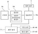
[도 1] 도 1은 본 발명의 일 실시예에 따른 간접형 로봇이 도시된 측면도이다.
[도 2] 도 2는 도 1의 로봇의 압력 검지 장치의 구성을 도시하는 블록도이다.
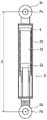
[도 3] 도 3은 도 1의 로봇의 가스 밸런서가 도시된 설명도이다.
[도 4] 도 4는 도 1의 로봇의 회동 암의 회동 각도(θ)와 가스 밸런서의 이론 압력 Pk(θ) 및 기준 압력 Pa(θ)의 관계가 도시된 그래프이다.
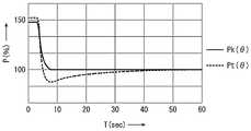
[도 5] 도 5는 도 1의 로봇의 회동 암을 회동시킬 때의 가스 밸런서의 이론 압력 Pk(θ)와 측정 압력 Pt(θ)의 관계가 도시된 그래프이다.[Figure 1] Figure 1 is a side view showing an indirect type robot according to an embodiment of the present invention.
[Fig. 2] Fig. 2 is a block diagram showing the configuration of the pressure detection device of the robot of Fig. 1;
[Fig. 3] Fig. 3 is an explanatory view showing a gas balancer of the robot of Fig. 1;
[FIG. 4] FIG. 4 is a graph showing the relationship between the rotation angle (θ) of the rotation arm of the robot of FIG. 1, the theoretical pressure Pk (θ), and the reference pressure Pa (θ) of the gas balancer.
[FIG. 5] FIG. 5 is a graph showing the relationship between the theoretical pressure Pk(θ) and the measured pressure Pt(θ) of the gas balancer when the rotation arm of the robot of FIG. 1 is rotated.
이하에서, 적절한 도면을 참조하면서 바람직한 실시예에 기초하여 본 발명이 상세하게 설명된다.DETAILED DESCRIPTION OF THE PREFERRED EMBODIMENTS Hereinafter, the present invention will be described in detail based on preferred embodiments with reference to appropriate drawings.
도 1에는 본 발명에 따른 로봇(2)이 도시되어 있다. 이러한 로봇(2)은 기대(基台)(4), 로봇 암(6), 가스 밸런서(8), 압력 센서(9) 및 가스압 검지 장치(10)를 구비하고 있다. 이러한 로봇(2)에서는, 압력 센서(9)는 가스 밸런서(8)의 내부에 배치되어 있다. 도시되지 않았지만, 이러한 로봇(2)은 나아가 구동 모터(M1 ~ M6)와 회전 센서(E1 ~ E6)를 구비하고 있다.1 shows a
로봇 암(6)은 제1 암(12), 제2 암(14), 제3 암(16), 제4 암(18), 제5 암(20) 및 제6 암(22)을 구비하고 있다. 이러한 로봇(2)에서는, 기대(4), 제1 암(12), 제2 암(14), 제3 암(16), 제4 암(18), 제5 암(20) 및 제6 암(22)이 순차적으로 연결되어 있다. 이러한 로봇(2)은 이러한 연결부로서 복수의 관절을 구비하고 있다. 이러한 로봇(2)은 이른바 다관절형 로봇이다.The
도 1에 도시된 바와 같이, 이러한 로봇(2)에서는, 제6 암(22)의 선단부에, 핸드(24)가 설치되어 있다. 이러한 핸드(24)는 도시되지 않는 워크(work)를 파지하는 기능을 구비하고 있다. 이러한 핸드(24)는 로봇(2)에 장착되는 툴(tool)의 예시이고, 다른 툴이 장착되어도 좋다.As shown in Fig. 1, in this
이러한 로봇(2)에서는, 제1 암(12)은 기대(4)에 연결되어 있다. 제1 암(12)은 상하 방향의 축선(L1)을 회전축으로 회전 가능하다. 제2 암(14)은 제1 암(12)에 연결되어 있다. 제2 암(14)은 수평 방향의 축선(L2)을 회동축으로 회동 가능하다. 제3 암(16)은 제2 암(14)에 연결되어 있다. 제3 암(16)은 수평 방향의 축선(L3)을 회동축으로 회동 가능하다. 제4 암(18)은 제3 암(16)에 연결되어 있다. 제4 암(18)은 축선(L4)을 회전축으로 회전 가능하다. 제5 암(20)은 제4 암(18)에 연결되어 있다. 제5 암(20)은 축선(L4)에 직교하는 축선(L5)을 회동축으로 회동 가능하다. 제6 암(22)은 제5 암(20)에 연결되어 있다. 제6 암(22)은 축선(L6)을 회전축으로 회전 가능하다.In this
도시되지 않은 구동 모터(M1)는 제1 암(12)을 회전시키는 기능을 구비하고 있다. 구동 모터(M2)는 제2 암(14)을 회동시키는 기능을 구비하고 있다. 마찬가지로, 구동 모터(M3)는 제3 암(16)을, 구동 모터(M5)는 제5 암(20)을 각각 회동시키는 기능을 구비하고, 구동 모터(M4)는 제4 암(18)을, 구동 모터(M6)는 제6 암(22)을 각각 회전시키는 기능을 구비하고 있다. 구동 모터(M1, M2, M3, M4, M5 및 M6)는, 예를 들어, 서보 모터이다.A drive motor M1, not shown, has a function of rotating the
회전 센서(E1)는 구동 모터(M1)의 회전 위치를 검출하는 기능을 구비하고 있다. 회전 센서(E2)는 구동 모터(M2)의 회전 위치를 검출하는 기능을 구비하고 있다. 마찬가지로, 회전 센서(E3, E4, E5 및 E6)는 구동 모터(M3, M4, M5 및 M6)의 회전 위치를 검출하는 기능을 구비하고 있다. 이러한 회전 센서(E1, E2, E3, E4, E5 및 E6)는, 예를 들어, 인코더이다.The rotation sensor E1 has a function of detecting the rotational position of the drive motor M1. The rotation sensor E2 has a function of detecting the rotational position of the drive motor M2. Similarly, the rotation sensors E3, E4, E5 and E6 have a function of detecting the rotational positions of the drive motors M3, M4, M5 and M6. These rotation sensors E1, E2, E3, E4, E5 and E6 are, for example, encoders.
가스 밸런서(8)는, 가스가 봉입되어 있다. 가스 밸런서(8)는 신축 가능하다. 가스 밸런서(8)의 신축에 따라서, 봉입된 가스의 압력이 변동한다. 이러한 가스의 압력의 변동에 의해, 가스 밸런서(8)는 신축력을 변동시킨다. 이러한 가스 밸런서(8)는 그 기단부(8b)가 제1 암(12)에 축에 의해 회전 가능하게 지지(축착; 軸着)되어 있다. 그의 선단부(8c)가 제2 암(14)에 축착되어 있다.The
도 1의 부호 Pa는 제2 암(14)의 회동 중심을 나타내고 있다. 기호 Pb는 가스 밸런서(8)의 기단부(8b)의 회동 중심을 나타내고 있다. 부호 Pc는 가스 밸런서(8)의 선단부(8c)의 회동 중심을 나타내고 있다. 부호 Pd는 제3 암(16)의 회동 중심을 나타내고 있다. 일점 쇄선 La는 회동 중심(Pa)과 회동 중심(Pd)을 통과하여 연장되는 직선을 나타내고 있다. 양방향 화살표(S)는 회동 중심(Pb)에서 회동 중심(Pc)까지의 거리를 나타내고 있다.Symbol Pa in FIG. 1 represents the center of rotation of the
부호 Pd'는 도 1의 자세로부터 제2 암(14)이 회동할 때의, 회동 중심(Pd)의 회동 위치를 나타내고 있다. 일점 쇄선 La'는 회동 중심(Pa)과 회동 위치(Pd')를 통과하여 연장되는 직선을 나타내고 있다. 양방향 화살표 θ는 제2 암(14)의 회동 각도를 나타내고 있다. 이러한 회동 각도(θ)는 직선(La)과 직선(La')이 이루는 각도이다. 제2 암(14)의 회동 각도(θ)는, 제2 암(14)이 도 1의 자세에 있을 때 0 °이다. 이러한 제2 암(14)이 도 1의 자세로부터 시계 방향으로 회동할 때 회동 각도(θ)는 양의 각도로 표시되고, 시계 반대 방향으로 회동할 때 회동 각도(θ)는 음의 각도로 표시된다.Symbol Pd' shows the rotation position of the rotation center Pd when the
제1 암(12)에 대해 제2 암(14)이 회동함으로써, 가스 밸런서(8)의 거리(S)는 변동한다. 이러한 거리(S)의 변동에 의해, 가스 밸런서(8)는 신축한다. 이러한 신축에 의해, 가스 밸런서(8)는 회동 중심(Pb)과 회동 중심(Pc) 사이에서, 신축력을 변동시킨다. 이러한 신축력에 의해, 가스 밸런서(8)는 제2 암(14)에 작용하는 하중을 지지하고, 구동 모터(M2)의 회전 부하를 경감한다.When the
압력 센서(9)는 가스 밸런서(8)에 장착되어 있다. 이러한 로봇(2)에서는, 가스 밸런서(8)의 내부에 장착되어 있다. 압력 센서(9)는 가스 밸런서(8)에 봉입된 가스의 압력을 측정하는 기능을 구비하고 있다. 압력 센서(9)는 가스 밸런서(8)의 밖에 장착되어도 좋다.A pressure sensor (9) is mounted on the gas balancer (8). In this
도 2에 도시된 바와 같이, 이러한 로봇(2)은 나아가 로봇 암(6)의 동작을 제어하는 제어 장치(11)를 구비하고 있다. 제어 장치(11)는 회전 센서(E1, E2, E3, E4, E5 및 E6)로부터 구동 모터(M1, M2, M3, M4, M5 및 M6)의 회전 위치 데이터를 수신하는 기능을 구비하고 있다. 제어 장치(11)는 제1 암(12), 제4 암(18) 및 제6 암(22)의 회전 위치를 산출하는 기능을 구비하고 있다. 제어 장치(11)는 제2 암(14), 제3 암(16) 및 제5 암(20)의 회동 위치를 산출하는 기능을 구비하고 있다. 제어 장치(11)는 구동 모터(M1, M2, M3, M4, M5 및 M6)를 제어하는 기능을 구비하고 있다.As shown in FIG. 2 , this
가스압 검지 장치(10)는 데이터의 입출력부로서의 인터페이스 보드(10a)와, 연산부로서의 프로세서(10b)와, 데이터의 기억부로서의 메모리(10c)를 구비하고 있다.The gas
이러한 인터페이스 보드(10a)는 제어 장치(11)로부터 제2 암(14)의 회동 위치 데이터(회동 각도(θ))를 수신하는 기능을 구비하고 있다. 인터페이스 보드(10a)는, 압력 센서(9)가 측정한 측정 압력 Pt(θ)의 데이터를 수신하는 기능을 구비하고 있다. 인터페이스 보드(10a)는 압력 이상의 신호를 경보 장치 등으로 송신하는 기능을 구비하고 있다.This
프로세서(10b)는 후술하는 기준 압력 Pa(θ)와 측정 압력 Pt(θ)의 대소 관계를 나타내는 변수 Rt(θ)와, 이러한 변수 Rt(θ)의 이동 평균 Rtj(θ)를 산출하는 산출부를 포함한다. 프로세서(10b)는 나아가 이러한 이동 평균 Rtj(θ)와 기준 값(R)을 비교하여 압력 저하를 검지하는 판정부를 포함한다. 프로세서(10b)는 압력 저하를 검지한 때, 인터페이스 보드(10a)에 압력 이상의 신호를 송신하는 기능을 구비하고 있다. 이러한 프로세서(10b)는, 인터페이스 보드(10a)가 수신한 회동 위치 데이터로부터 회동 각도(θ)를 산출하여도 좋다.The
메모리(10c)는 제2 암(14)의, 회동 각도(θ)와 회동 각도(θ)에서 기준 압력 Pa(θ)를 기억하는 기능을 구비하고 있다. 이러한 기준 압력 Pa(θ)는 회동 각도(θ)에서 가스 밸런서(8)의 가동 허용 압력이다. 메모리(10c)는 압력 센서(9)로부터 얻어진 측정 압력 Pt(θ)와 이러한 측정 압력 Pt(θ)가 측정된 때의 회동 각도(θ)를 대응시켜 기억하는 기능을 구비하고 있다.The
도 3에 도시된 바와 같이, 가스 밸런서(8)는 실린더(26) 및 피스톤(28)을 구비하고 있다. 실린더(26)는 기단부(8b)에 연결되어 있다. 피스톤(28)은 선단부(8c)에 연결되어 있다. 이러한 피스톤(28)이 실린더(26)에 슬라이딩 가능하게 삽입되어 있다. 이러한 피스톤(28)과 실린더(26)가 가스실(30)을 형성하고 있다. 이러한 가스실(30)에는, 고압의 가스가 봉입되어 있다. 이러한 가스는 특별히 한정되지 않지만, 예를 들어 불활성 가스이다. 이러한 가스 밸런서(8)는, 거리(S)가 변화함으로써, 신축한다. 이러한 신축에 의해, 가스실(30)의 용적이 변화한다. 이러한 용적의 변화에 의해, 가스의 압력이 변화한다. 압력 센서(9)는 이러한 가스의 압력을 측정한다.As shown in FIG. 3 ,
이러한 가스 밸런서(8)에서는, 그 길이가 신장한 때에, 그 길이가 축소되는 방향의 신축력이 작용한다. 이에 따라서, 가스 밸런서(8)는 구동 모터(M2)의 회전 부하를 경감한다. 이러한 가스 밸런서(8)는 구동 모터(M2)의 회전 부하를 경감하도록 구성되어 있으면 좋다. 가스 밸런서(8)는, 그 길이가 수축한 때에, 그 길이가 연장되는 방향의 신축력이 작용하는 것이라도 좋다. 가스 밸런서(8)의 길이가 수축한 때에, 그 길이가 연장되는 방향의 신축력을 작용시켜서, 구동 모터(M2)의 회전 부하를 경감하도록 구성되어도 좋다.In such a
도 4에는 제2 암(14)의 회동 각도(θ)와 가스 밸런서(8)의 이론 압력 Pk(θ)및 기준 압력 Pa(θ)의 관계가 도시되어 있다. 이러한 이론 압력 Pk(θ)는 회동 각도(θ)에서 가스실(30)의 용적으로부터 계산하여 구해지는 압력이다. 이러한 로봇(2)에서는, 제2 암(14)의 회동 각도(θ)가 9 °일 때, 가스실(30)의 용적이 최대이고, 이론 압력 Pk(θ)가 최소이다. 도 4에서는, 회동 각도(θ)가 9 °일 때의 이론 압력 Pk(θ)를 100 (%)로 하는 지수로, 이론 압력 Pk(θ) 및 기준 압력 Pa(θ)가 표시되어 있다. 기준 압력 Pa(θ)는 회동 각도(θ)에서 가동 허용 압력을 나타내고 있다. 이러한 기준 압력 Pa(θ)는 제2 암(14)의 가동 가능한 압력인지 여부의 판단에 사용되는 기준 압력이라면 좋고, 그 산출 방법은 특별히 한정되지 않는다. 기준 압력 Pa(θ)는, 예를 들어, 이론 압력 Pk(θ)와 1 보다 작은 양의 계수 B의 곱으로 산출되는 압력이라도 좋고, 이론 압력 Pk(θ)로부터 소정의 압력을 제하고 산출되는 압력이라도 좋다.4 shows the relationship between the rotation angle θ of the
여기서, 이러한 로봇(2)을 이용하여, 본 발명에 따른 가스의 압력 저하의 검지 방법이 설명된다. 여기에서는, 가스 밸런서(8)의 가스의 압력 저하의 검지를 예로 들어 설명이 된다. 여기에서는, 제1 암(12)이 암 지지부이고, 제2 암(14)은 회동 암이다.Here, using such a
가스압 검지 장치(10)의 메모리(10c)는 회동 각도(θ)와 회동 각도(θ)의 기준 압력 Pa(θ)를 기억하고 있다. 인터페이스 보드(10a)는 회동 각도(θ)와 측정 압력 Pt(θ)를 수신한다(STEP 1). 이러한 메모리(10c)는, 소정의 시간 간격마다, 회동 각도(θ)와 측정 압력 Pt(θ)를 기억한다. 예를 들어, 이러한 가스압 검지 장치(10)는 시각(t1)에서 시각(tn)(n은 자연수)까지의 각각의 시각(t)에서, n 개의 회동 각도(θ)와 측정 압력 Pt(θ)가 기억된다.The
가스압 검지 장치(10)의 프로세서(10b)(산출부)는, 회동 각도(θ)에서, 기준 압력 Pa(θ)와 측정 압력 Pt(θ)의 대소 관계를 나타내는 변수 Rt(θ)를 산출한다(STEP 2). 구체적으로는, 예를 들어, 계수 A로 하여, 이하의 식 (1)으로 나타낸 비율을 변수 Rt(θ)로 산출한다.The
[수 1][number 1]

이러한 프로세서(10b)는 소정의 시간 간격마다 얻어지는 복수의 측정 압력 Pt(θ)로부터 복수의 변수 Rt(θ)를 산출한다. 이러한 프로세서(10b)는, 복수의 변수 Rt(θ)로부터 시각(tj)에서 이동 평균 Rtj(θ)를 산출한다(STEP 3). 구체적으로는, 예를 들어, 이하의 수식 (2)에서 구해진다. 이러한 수식 (2)에서, Rtj(θ)는 j 번째(j는 n 이하의 자연수)의 시각(tj)의 이동 평균을 나타낸다. 이러한 이동 평균 Rtj(θ)는 i 번째(i는 j보다 작은 자연수)의 시각(ti)에서 시각(tj)까지 얻어진 변수 Rt(θ)의 평균값으로서 구해지고 있다.This
[수 2][number 2]

가스압 검지 장치(10)의 프로세서(10b)(판정부)는, 이러한 이동 평균 Rtj(θ)와 기억된 기준 값(R)을 비교하여, 가스 밸런서(8)의 가스의 압력 저하를 검지한다(STEP 4). 이러한 가스압 검지 장치(10)는 소정의 시간 간격의 시각마다, 이동 평균 Rtj(θ)의 산출을 반복한다. 예를 들어, 프로세서(10b)는, 이동 평균 Rtj(θ)가 기준 값(R) 이상일 때, 가스 밸런서(8)의 압력은 가동 가능한 허용 범위로 판단한다. 프로세서(10b)는, 이러한 이동 평균 Rtj(θ)가 기준 값(R) 미만이면, 가스 밸런서(8)의 압력이 가동 가능한 허용 범위를 하회하였다고 판정한다. 이 때, 프로세서(10b)는 인터페이스 보드(10a)에 압력 이상의 신호를 송신한다. 이러한 압력 이상의 신호에 의해, 예를 들어, 경고등을 점등하고, 로봇(2)이 정지된다.The
도 5에는 제2 암(14)을 회동시켰을 때의 실제의 측정 압력 Pt(θ)와 이론 압력 Pk(θ)의 관계가 도시되어 있다. 도 5에서는, 회동 각도(θ)가 9 °일 때의 이론 압력 Pk(θ)를 100 (%)로 하는 지수로, 이론 압력 Pk(θ) 및 측정 압력 Pt(θ)가 표시되어 있다. 이러한 도 5에서는, 제2 암(14)을 회동 각도(θ)를 90 °로 회동시키고, 그 후에 9 °로 회동시켜서, 압력 센서(9)에서 얻어진 측정 압력 Pt(θ)가 표시되어 있다. 이러한 측정 압력 Pt(θ)를 얻는 것과 마찬가지로, 제2 암(14)을 회동시켰을 때의 이론 압력 Pk(θ)가 표시되어 있다.FIG. 5 shows the relationship between the actual measured pressure Pt(θ) and the theoretical pressure Pk(θ) when the
도 5에서, 제2 암(14)이 회동 각도(θ)를 90 °로 회동하였을 때에, 가스 밸런서(8)가 신장하여 가스실(30)의 용적은 감소하고 있다. 봉입된 가스는 압축된다. 이 때의 이론 압력 Pk(θ)는 약 148 (%)이다. 제2 암(14)이 회동 각도(θ)를 9 °로 회동하였을 때에, 가스 밸런서(8)가 수축하여 가스실(30)의 용적은 확대하고 있다. 봉입된 가스는 팽창하게 된다. 이 때의 이론 압력 Pk(θ)는 100 (%)이다. 제2 암(14)의 회동에 의해, 이론 압력 Pk(θ)는 약 148 (%)로부터 100 (%)로 변화하고 있다.In FIG. 5 , when the
이에 반해서, 제2 암(14)이 회동 각도(θ)를 90 °로 회동하였을 때에, 실제로 얻어진 측정 압력 Pt(θ)는 약 152 (%)이다. 이러한 측정 압력 Pt(θ)는 이론 압력 Pk(θ)의 약 148 (%) 보다 높다. 제2 암(14)이 회동 각도(θ)를 9 °로 회동하였을 때에, 측정 압력 Pt(θ)는 약 88 (%)로 저하된 후, 시간(T)(sec)의 경과에 의해, 약 100 (%)까지 점차 증가하고 있다. 이러한 측정 압력 Pt(θ)와 이론 압력 Pk(θ)의 차이는 시간의 경과에 의해 점차 감소하고 있다.In contrast, when the
도 5에 도시된 바와 같이, 이론 압력 Pk(θ)와 측정 압력 Pt(θ)사이에는 차이가 생기고 있다. 이러한 압력차는, 제2 암(14)이 회동하였을 때에 일시적으로 증가한다. 이것은, 제2 암(14)의 회동에 의해, 가스실(30)에 봉입된 가스는 일시적으로 단열 변화에 가까운 압력 변화를 하는데 따른 것이다. 구체적으로는, 이러한 가스실(30)에서는, 봉입된 가스가 팽창되는 때에, 가스의 온도가 저하된다. 가스실(30)의 용적의 변화에 의한 압력 저하에 더하여, 온도의 저하에 의한 압력 저하를 일으킨다. 그 후에, 가스의 온도의 상승에 따라서 압력이 서서히 상승한다. 마찬가지로, 가스가 압축될 때에는, 가스의 온도가 상승한다. 가스실(30)의 용적의 변화에 의한 압력 상승에 더해, 온도의 상승에 의한 압력 상승을 일으킨다. 그 후에, 이러한 가스의 온도 저하에 따라서 압력이 서서히 저하된다. 이러한 현상에 의해, 도 5에 표시된 측정 압력 Pt(θ)가 얻어진다.As shown in Fig. 5, there is a difference between the theoretical pressure Pk(θ) and the measured pressure Pt(θ). This pressure difference temporarily increases when the
상술한 압력 강하의 검출 방법에서는, 가스압 검지 장치(10)는 기준 압력 Pa(θ)에 대한 상기 측정 압력 Pt(θ)의 비율(Pt(θ)/Pa(θ))을 변수 Rt(θ)로서 산출하고 있다. 이러한 변수 Rt(θ)를 산출함으로써, 측정 시각(t) 당 측정 압력 Pt(θ)와 기준 압력 P(a)의 대소 관계가 평가되고 있다. 가스압 검지 장치(10)는 나아가 이러한 변수 Rt(θ)의 이동 평균 Rtj(θ)를 산출하고 있다. 이동 평균 Rtj(θ)를 이용함으로써, 가스압 검지 장치(10)는 이론 압력 Pk(θ)와 측정 압력 Pt(θ)의 일시적인 차이의 영향을 저감하고 있다. 이에 따라서, 가스 밸런서(8)의 가스의 압력 저하의 오 검지가 억제된다.In the pressure drop detection method described above, the gas
이러한 측정 압력 Pt(θ)를 얻는 측정 시각(t)의 간격을 짧게 함으로써, 가스의 압력의 변화를 정밀하게 파악하고 있다. 이러한 관점에서, 측정 시각(t)의 간격은, 바람직하게는 1 초 이하이고, 더 바람직하게는 0.5 초 이하이며, 특히 바람직하게는 0.1 초 이하이다. 이러한 측정 시각(t)의 간격에 특별한 하한은 없다. 이러한 측정 시각(t)의 간격은 압력 센서(9)에 의해 정해진 측정 간격의 하한 값 이상이라도 좋다.By shortening the interval of the measurement time t for obtaining such a measurement pressure Pt(θ), the change in gas pressure is grasped precisely. From this point of view, the interval of measurement time t is preferably 1 second or less, more preferably 0.5 second or less, and particularly preferably 0.1 second or less. There is no particular lower limit to the interval of this measurement time t. The interval of this measurement time t may be equal to or greater than the lower limit of the measurement interval determined by the
측정 압력 Pt(θ)를 얻는 측정 시간(시각ti에서 시각tj까지의 시간)을 길게 함으로써, 제2 암(14)의 회동에 의한 일시적 차이의 영향을 저감할 수 있다. 이러한 관점에서, 이러한 시간은, 바람직하게는, 10 초 이상이고, 더 바람직하게는 30 초 이상이며, 특히 바람직하게는 60 초 이상이다. 이러한 측정 시간은 길수록 일시적 차이의 영향을 저감할 수 있기 때문에, 예를 들어 200 초 이상이라도 좋다. 특히, 이러한 측정 시간에 상한은 없지만, 이러한 시간이 긴 가스압 검지 장치(10)에서는, 압력 저하의 검지가 늦어진다. 신속하게 압력 저하를 검지하는 관점에서, 이러한 시간은, 바람직하게는 600 초 이하이다.By lengthening the measurement time (time from time ti to time tj) for obtaining the measurement pressure Pt(θ), the influence of the temporary difference due to the rotation of the
이러한 변수 Rt(θ)는 기준 압력 Pa(θ)와 측정 압력 Pt(θ)의 대소 관계를 나타내는 것이라면 좋고, 비율(Pt(θ)/Pa(θ))에 한정되지 않는다. 예를 들어, 이러한 변수 Rt(θ)는 기준 압력 Pa(θ)와 측정 압력 Pt(θ)의 차이에 기초한 것이라도 좋다. 구체적으로는, 가스압 검지 장치(10)는 이러한 변수 Rt(θ)로서, 기준 압력 Pa(θ)와 측정 압력 Pt(θ)의 차이(Pt(θ)- Pa(θ))를 산출한다. 이러한 변수 Rt(θ)로부터 산출되는 이동 평균 Rtj(θ)가 소정의 수 값, 예를 들어 0 보다 작을 때, 가스압 검지 장치(10)는, 가스의 압력이 가동 허용 압력을 하회하였다고 검지하여도 좋다. 이러한 변수 Rt(θ)로서, 차이(Pt(θ)-Pa(θ))와 계수 A의 곱이 이용되어도 좋다. 나아가, 기준 압력 Pa(θ) 또는 측정 압력 Pt(θ)에 대하여, 차이(Pt(θ)-Pa(θ))의 비율이 산출되어도 좋다.The variable Rt(θ) may be anything that represents a magnitude relationship between the reference pressure Pa(θ) and the measured pressure Pt(θ), and is not limited to the ratio Pt(θ)/Pa(θ). For example, this variable Rt(θ) may be based on the difference between the reference pressure Pa(θ) and the measured pressure Pt(θ). Specifically, the gas
이러한 로봇(2)에서는, 제2 암(14)이 본 발명에 따른 회동 암으로, 제1 암(12)이 본 발명에 따른 암 지지부로 설명되었지만 이에 제한되지 않는다. 예를 들어, 제2 암(14)과 제3 암(16)의 사이에 가스 스프링이 설치되고, 제2 암(14)이 암 지지부로 되고, 제3 암(16)이 회동 암으로 되어도 좋다. 마찬가지로, 제4 암(18)과 제5 암(20)의 사이에 가스 스프링이 설치되고, 제4 암(18)이 암 지지부가 되고, 제5 암(20)이 회동 암으로 되어도 좋다. 여기에서는, 본 발명에 따른 로봇(2)은 다관절형 로봇을 예로 설명되었지만, 암 지지부와 회동 암을 구비하는 관절형 로봇이라면 좋다.In this
2 ... 로봇
4 ... 기대
6 ... 로봇 암
8 ... 가스 밸런서
9 ... 압력 센서
10 ... 가스압 검지 장치
10a ··· 인터페이스 보드
10b ... 프로세서
10c ... 메모리
12 ... 제1 암(암 지지부)
14 ... 제2 암(회동 암)
26 ... 실린더
28 ... 피스톤
30 ... 가스실2 ... Robot
4 ... Expect
6 ... robot arm
8 ... gas balancer
9 ... pressure sensor
10 ... gas pressure detection device
10a ... interface board
10b ... processor
10c ... memory
12 ... first arm (arm support)
14 ... 2nd arm (rotation arm)
26 ... cylinder
28 ... Piston
30 ... gas chamber
Claims (8)
Translated fromKorean상기 회동 암의 회동 각도(θ)에서의 기준 압력 Pa(θ)와 상기 회동 각도(θ)에서 상기 압력 센서가 측정하여 얻은 측정 압력 Pt(θ)의 대소 관계를 나타내는 변수 Rt(θ)를 산출하고, 측정 시각이 다른 복수의 상기 측정 압력 Pt(θ)로부터 복수의 상기 변수 Rt(θ)를 산출하고, 상기 측정 압력 Pt(θ)의 j 번째(j는 2 이상의 자연수)의 측정 시각(tj)에서의 상기 변수 Rt(θ)의 이동 평균 Rtj(θ)를 산출하는 산출부와,
상기 이동 평균 Rtj(θ)와 기준 값(R)을 비교하여 상기 가스의 압력 저하를 검지하는 판정부를 구비하는 것을 특징으로 하는 가스압 검지 장치.In a robot including an arm support, a rotational arm rotatably supported by the arm support, a gas balancer for reducing a rotational load of the rotational arm, and a pressure sensor for measuring a gas pressure of the gas balancer, the pressure As a gas pressure detection device for detecting a decrease in
Calculate variable Rt(θ) representing the magnitude relationship between the reference pressure Pa(θ) at the rotation angle θ of the rotation arm and the measured pressure Pt(θ) obtained by measuring the pressure sensor at the rotation angle θ and calculates a plurality of variables Rt(θ) from a plurality of measured pressures Pt(θ) at different measurement times, and calculates the jth measurement time (tj is a natural number of 2 or more) of the measured pressure Pt(θ) (j is a natural number equal to or greater than 2). A calculation unit for calculating a moving average Rtj (θ) of the variable Rt (θ) in );
and a determination unit for detecting a drop in pressure of the gas by comparing the moving average Rtj (θ) with a reference value (R).
상기 산출부에서 산출하는 상기 변수 Rt(θ)가 상기 기준 압력 Pa(θ)와 상기 측정 압력 Pt(θ)로부터 계수 A로 하여 하기의 수식 (1)로 표시되는 것을 특징으로 하는 가스압 검지 장치.
[수 1]

The gas pressure detection device according to claim 1, wherein the variable Rt(θ) calculated by the calculator is expressed by the following formula (1) as a coefficient A from the reference pressure Pa(θ) and the measured pressure Pt(θ).
[number 1]
상기 산출부가 산출하는 상기 이동 평균 Rtj(θ)가 i 번째(i는 1 이상의 자연수)의 측정 시각(ti)에서 j 번째(j는 i보다 큰 자연수)의 측정 시각(tj)까지 얻어지는 복수의 상기 변수 Rt(θ)를 이용하여 하기의 수식 (2)로 표시되는 것을 특징으로 하는 가스압 검지 장치.
[수 2]

The moving average Rtj(θ) calculated by the calculator is obtained from the i-th (i is a natural number greater than or equal to 1) measurement time ti to the j-th (j is a natural number greater than i) measurement time tj. A gas pressure detection device characterized in that it is expressed by the following formula (2) using the variable Rt(θ).
[number 2]
상기 산출부가 상기 이동 평균 Rtj(θ)의 산출에 이용하는 복수의 상기 측정 압력 Pt(θ)의 측정 시각의 간격이 1 초 이하인 것을 특징으로 하는 가스압 검지 장치.According to claim 1 or 2,
The gas pressure detection device according to claim 1 , wherein an interval between measurement times of a plurality of the measured pressures Pt(θ) used by the calculator to calculate the moving average Rtj(θ) is 1 second or less.
상기 산출부가 상기 이동 평균 Rtj(θ)의 산출에 이용하는 복수의 상기 측정 압력 Pt(θ)를 얻는 측정 시간이 10 초 이상인 것을 특징으로 하는 가스압 검지 장치.According to claim 1 or 2,
The gas pressure detection device according to claim 1, wherein a measurement time for obtaining a plurality of the measured pressures Pt(θ) used by the calculator to calculate the moving average Rtj(θ) is 10 seconds or more.
상기 산출부가 상기 이동 평균 Rtj(θ)의 산출에 이용하는 복수의 상기 측정 압력 Pt(θ)를 얻는 측정 시간이 600 초 이하인 것을 특징으로 하는 가스압 검지 장치.According to claim 5,
The gas pressure detection device according to claim 1 , wherein a measurement time for obtaining a plurality of the measured pressures Pt(θ) used by the calculator to calculate the moving average Rtj(θ) is 600 seconds or less.
상기 가스압 검지 장치가,
상기 회동 암의 회동 각도(θ)에서의 기준 압력 Pa(θ)와 상기 회동 각도(θ)에서 상기 압력 센서가 측정하여 얻은 측정 압력 Pt(θ)의 대소 관계를 나타내는 변수 Rt(θ)를 산출하고, 측정 시각이 다른 복수의 상기 측정 압력 Pt(θ)로부터 복수의 상기 변수 Rt(θ)를 산출하고, 상기 측정 압력 Pt(θ)의 j 번째(j는 2 이상의 자연수)의 측정 시각(tj)에서의 상기 변수 Rt(θ)의 이동 평균 Rtj(θ)를 산출하는 산출부와,
상기 이동 평균 Rtj(θ)와 기준 값(R)을 비교하여 상기 가스의 압력 저하를 검지하는 판정부를 구비하는 것을 특징으로 하는 로봇.An arm support, a rotational arm rotatably supported by the arm support, a gas balancer for reducing a rotational load of the rotational arm, a pressure sensor for measuring a gas pressure of the gas balancer, and detecting a decrease in the pressure It is provided with a gas pressure detection device that
The gas pressure detection device,
Calculate variable Rt(θ) representing the magnitude relationship between the reference pressure Pa(θ) at the rotation angle θ of the rotation arm and the measured pressure Pt(θ) obtained by measuring the pressure sensor at the rotation angle θ and calculates a plurality of variables Rt(θ) from a plurality of measured pressures Pt(θ) at different measurement times, and calculates the jth measurement time (tj is a natural number of 2 or more) of the measured pressure Pt(θ) (j is a natural number equal to or greater than 2). A calculation unit for calculating a moving average Rtj (θ) of the variable Rt (θ) in );
A robot characterized by comprising a determination unit that compares the moving average Rtj (θ) with a reference value (R) and detects a drop in pressure of the gas.
(A) 상기 압력 센서로 상기 가스 밸런서의 가스의 압력을 측정하여 상기 회동 암의 회동 각도(θ)에서의 측정 압력 Pt(θ)를 얻는 스텝,
(B) 상기 측정 압력 Pt(θ)와 상기 회동 암의 회동 각도(θ)에서의 기준 압력 Pa(θ)의 대소 관계를 나타내는 변수 Rt(θ)를 산출하는 스텝,
(C) 측정 시각이 다른 복수의 상기 측정 압력 Pt(θ)로부터 복수의 상기 변수 Rt(θ)를 산출하고, 상기 측정 압력 Pt(θ)의 j 번째(j는 2 이상의 자연수)의 측정 시각(tj)에서의 상기 변수 Rt(θ)의 이동 평균 Rtj(θ)를 산출하는 스텝, 및
(D) 상기 이동 평균 Rtj(θ)와 기준 값(R)을 비교하여 상기 가스의 압력 저하를 검지하는 스텝을 포함하는 것을 특징으로 하는 가스압 검지 방법.In a robot including an arm support, a rotational arm rotatably supported by the arm support, a gas balancer for reducing a rotational load of the rotational arm, and a pressure sensor for measuring a gas pressure of the gas balancer, the gas As a method of detecting a pressure drop of the gas of the balancer,
(A) measuring the gas pressure of the gas balancer with the pressure sensor to obtain the measured pressure Pt(θ) at the rotation angle θ of the rotation arm;
(B) calculating a variable Rt(θ) representing a magnitude relationship between the measured pressure Pt(θ) and the reference pressure Pa(θ) at the rotation angle θ of the rotation arm;
(C) Calculate a plurality of variables Rt (θ) from a plurality of measured pressures Pt (θ) at different measurement times, and measure the jth (j is a natural number of 2 or more) measurement time (j is a natural number of 2 or more) of the measured pressure Pt (θ) calculating a moving average Rtj(θ) of the variable Rt(θ) at tj), and
(D) comparing the moving average Rtj (θ) with a reference value (R) to detect a drop in pressure of the gas.
Applications Claiming Priority (3)
| Application Number | Priority Date | Filing Date | Title |
|---|---|---|---|
| JP2018224917AJP7089460B2 (en) | 2018-11-30 | 2018-11-30 | A robot equipped with a gas pressure detection device and a gas pressure detection device and its gas pressure detection method |
| JPJP-P-2018-224917 | 2018-11-30 | ||
| PCT/JP2019/046561WO2020111179A1 (en) | 2018-11-30 | 2019-11-28 | Gas pressure detection device, robot comprising gas pressure detection device, and gas pressure detection method for same |
Publications (2)
| Publication Number | Publication Date |
|---|---|
| KR20210092276A KR20210092276A (en) | 2021-07-23 |
| KR102487273B1true KR102487273B1 (en) | 2023-01-11 |
Family
ID=70853841
Family Applications (1)
| Application Number | Title | Priority Date | Filing Date |
|---|---|---|---|
| KR1020217018563AActiveKR102487273B1 (en) | 2018-11-30 | 2019-11-28 | Gas pressure detection device, robot equipped with gas pressure detection device, and gas pressure detection method thereof |
Country Status (6)
| Country | Link |
|---|---|
| US (1) | US12064871B2 (en) |
| EP (1) | EP3889564A4 (en) |
| JP (1) | JP7089460B2 (en) |
| KR (1) | KR102487273B1 (en) |
| CN (1) | CN113167671B (en) |
| WO (1) | WO2020111179A1 (en) |
Families Citing this family (4)
| Publication number | Priority date | Publication date | Assignee | Title |
|---|---|---|---|---|
| JP7473317B2 (en)* | 2019-10-11 | 2024-04-23 | ファナック株式会社 | Gas spring maintenance management device, robot system, and gas spring maintenance management method |
| JP7601888B2 (en)* | 2020-09-17 | 2024-12-17 | ファナック株式会社 | Balancer and Robot Systems |
| CN114739562A (en)* | 2021-01-07 | 2022-07-12 | 配天机器人技术有限公司 | Nitrogen spring pressure monitoring system for industrial robot and industrial robot |
| CN120039655B (en)* | 2025-04-24 | 2025-07-08 | 浙江星壹建设有限公司 | A palletizing device for conveying building materials |
Citations (1)
| Publication number | Priority date | Publication date | Assignee | Title |
|---|---|---|---|---|
| WO2017155071A1 (en) | 2016-03-09 | 2017-09-14 | 川崎重工業株式会社 | Articulated robot and method for estimating reduced state of gas in gas springs |
Family Cites Families (16)
| Publication number | Priority date | Publication date | Assignee | Title |
|---|---|---|---|---|
| JPS5512706B2 (en) | 1972-07-03 | 1980-04-03 | ||
| JPS5895307U (en)* | 1981-12-22 | 1983-06-28 | 富士重工業株式会社 | Automotive air suspension vehicle height adjustment device |
| JPH01310885A (en)* | 1988-06-07 | 1989-12-14 | Mitsubishi Electric Corp | industrial robot equipment |
| DE59100174D1 (en)* | 1990-03-21 | 1993-08-12 | Siemens Ag | INDUSTRIAL ROBOT. |
| JPH05228884A (en)* | 1992-02-19 | 1993-09-07 | Tokico Ltd | Industrial robot |
| DE19837595B4 (en) | 1998-08-19 | 2004-06-03 | Kuka Roboter Gmbh | Method and device for balancing the weight of a robot arm |
| US6689074B2 (en)* | 2000-03-28 | 2004-02-10 | Seiko Epson Corporation | Wearable muscular-force supplementing device |
| JP4180802B2 (en)* | 2001-01-30 | 2008-11-12 | 本田技研工業株式会社 | Tire pressure detector |
| JP3665013B2 (en)* | 2001-11-09 | 2005-06-29 | 本田技研工業株式会社 | Leg joint assist device for legged mobile robot |
| JP4495103B2 (en)* | 2006-03-27 | 2010-06-30 | 三菱電機株式会社 | Gas leak detection device and gas leak detection method |
| SE533463C2 (en) | 2009-02-26 | 2010-10-05 | Stroemsholmen Ab | Balancing device for balancing two relatively moving parts including a gas spring and method for balancing |
| JP2011000909A (en)* | 2009-06-16 | 2011-01-06 | Sanwa Tekki Corp | Gas pressure type tension balancer of overhead wire |
| CN201723633U (en)* | 2010-07-01 | 2011-01-26 | 深圳市蓝韵实业有限公司 | Adjustable connecting rod support |
| JP5628953B2 (en)* | 2013-03-29 | 2014-11-19 | ファナック株式会社 | Articulated robot with gas spring and method for estimating internal pressure of gas spring |
| JP5941083B2 (en)* | 2014-03-12 | 2016-06-29 | ファナック株式会社 | Robot controller that detects contact with external environment |
| WO2015148370A1 (en)* | 2014-03-24 | 2015-10-01 | Abb Technology Ag | Hydraulic/pneumatic cylinder as balancer units |
- 2018
- 2018-11-30JPJP2018224917Apatent/JP7089460B2/enactiveActive
- 2019
- 2019-11-28KRKR1020217018563Apatent/KR102487273B1/enactiveActive
- 2019-11-28CNCN201980077482.1Apatent/CN113167671B/enactiveActive
- 2019-11-28EPEP19888528.7Apatent/EP3889564A4/enactivePending
- 2019-11-28WOPCT/JP2019/046561patent/WO2020111179A1/ennot_activeCeased
- 2019-11-28USUS17/290,647patent/US12064871B2/enactiveActive
Patent Citations (1)
| Publication number | Priority date | Publication date | Assignee | Title |
|---|---|---|---|---|
| WO2017155071A1 (en) | 2016-03-09 | 2017-09-14 | 川崎重工業株式会社 | Articulated robot and method for estimating reduced state of gas in gas springs |
Also Published As
| Publication number | Publication date |
|---|---|
| US20210387362A1 (en) | 2021-12-16 |
| US12064871B2 (en) | 2024-08-20 |
| CN113167671B (en) | 2023-04-04 |
| JP2020085831A (en) | 2020-06-04 |
| CN113167671A (en) | 2021-07-23 |
| JP7089460B2 (en) | 2022-06-22 |
| KR20210092276A (en) | 2021-07-23 |
| EP3889564A1 (en) | 2021-10-06 |
| EP3889564A4 (en) | 2022-08-31 |
| WO2020111179A1 (en) | 2020-06-04 |
Similar Documents
| Publication | Publication Date | Title |
|---|---|---|
| KR102487273B1 (en) | Gas pressure detection device, robot equipped with gas pressure detection device, and gas pressure detection method thereof | |
| JP7044792B2 (en) | Pressure type load detection system | |
| US20120185092A1 (en) | Robotic arm position controlling device and robotic arm having same | |
| JP2004264135A (en) | Multi-articulated coordinate measuring system | |
| US20130087522A1 (en) | Method for load torque limitation of a working vehicle comprising a jib | |
| JP6808828B2 (en) | A method for determining the load and a control device for a hydraulic lifting device to carry out such a method. | |
| US20200164529A1 (en) | Articulated robot and method of estimating decrease state of gas in gas spring | |
| US11376731B2 (en) | Articulated robot and method of estimating reduced state of gas in gas spring of the articulated robot | |
| JP5638077B2 (en) | Method and control device for determining the height of a working device with swivel elements | |
| US7519499B2 (en) | Programmable position sensing system with a memory component | |
| KR102427532B1 (en) | Error detection apparatus and error detection method | |
| KR20110062833A (en) | Apparatus and method for weighing loads using compensation pressure according to the change of hydraulic oil temperature | |
| JP4168816B2 (en) | Robot control device | |
| US20230393022A1 (en) | Method for determining a bearing friction | |
| JP2020037172A (en) | robot | |
| JP7133558B2 (en) | Apparatus and method for measuring ballast of cranes, and cranes thereof | |
| JP6081232B2 (en) | Hydraulic device, hydraulic system, control method of hydraulic device, and control method of hydraulic system | |
| KR102100121B1 (en) | Electric press, a method to select a loadcell and a program thereof | |
| WO2025027787A1 (en) | Control device, parameter correction method, and program | |
| IT8323243A1 (en) | EQUIPMENT FOR SUPPORTING A LOAD WITH MEANS OF MEASURING THE LOAD AND METHOD FOR DETERMINING THE SIZE OF THE LOAD | |
| CN120702665A (en) | Calibration method and calibration system of force transducer, electronic equipment and storage medium | |
| CN120461418A (en) | Control method and system for mechanical arm | |
| KR19990013150A (en) | Displacement correction method of stroke sensing cylinder | |
| JPH1162462A (en) | Oil quantity detecting device of hydraulic cylinder of drilling machine | |
| KR20130081793A (en) | System and method for monitering distortion on an object |
Legal Events
| Date | Code | Title | Description |
|---|---|---|---|
| PA0105 | International application | St.27 status event code:A-0-1-A10-A15-nap-PA0105 | |
| PA0201 | Request for examination | St.27 status event code:A-1-2-D10-D11-exm-PA0201 | |
| PG1501 | Laying open of application | St.27 status event code:A-1-1-Q10-Q12-nap-PG1501 | |
| E902 | Notification of reason for refusal | ||
| PE0902 | Notice of grounds for rejection | St.27 status event code:A-1-2-D10-D21-exm-PE0902 | |
| P11-X000 | Amendment of application requested | St.27 status event code:A-2-2-P10-P11-nap-X000 | |
| P13-X000 | Application amended | St.27 status event code:A-2-2-P10-P13-nap-X000 | |
| E701 | Decision to grant or registration of patent right | ||
| PE0701 | Decision of registration | St.27 status event code:A-1-2-D10-D22-exm-PE0701 | |
| PR0701 | Registration of establishment | St.27 status event code:A-2-4-F10-F11-exm-PR0701 | |
| PR1002 | Payment of registration fee | St.27 status event code:A-2-2-U10-U12-oth-PR1002 Fee payment year number:1 | |
| PG1601 | Publication of registration | St.27 status event code:A-4-4-Q10-Q13-nap-PG1601 |