KR102483990B1 - Adaptive beamforming method and active sonar using the same - Google Patents
Adaptive beamforming method and active sonar using the sameDownload PDFInfo
- Publication number
- KR102483990B1 KR102483990B1KR1020210000843AKR20210000843AKR102483990B1KR 102483990 B1KR102483990 B1KR 102483990B1KR 1020210000843 AKR1020210000843 AKR 1020210000843AKR 20210000843 AKR20210000843 AKR 20210000843AKR 102483990 B1KR102483990 B1KR 102483990B1
- Authority
- KR
- South Korea
- Prior art keywords
- time
- series
- signal
- generating
- signals
- Prior art date
- Legal status (The legal status is an assumption and is not a legal conclusion. Google has not performed a legal analysis and makes no representation as to the accuracy of the status listed.)
- Active
Links
Images


Classifications
- G—PHYSICS
- G01—MEASURING; TESTING
- G01S—RADIO DIRECTION-FINDING; RADIO NAVIGATION; DETERMINING DISTANCE OR VELOCITY BY USE OF RADIO WAVES; LOCATING OR PRESENCE-DETECTING BY USE OF THE REFLECTION OR RERADIATION OF RADIO WAVES; ANALOGOUS ARRANGEMENTS USING OTHER WAVES
- G01S7/00—Details of systems according to groups G01S13/00, G01S15/00, G01S17/00
- G01S7/52—Details of systems according to groups G01S13/00, G01S15/00, G01S17/00 of systems according to group G01S15/00
- G01S7/523—Details of pulse systems
- G—PHYSICS
- G01—MEASURING; TESTING
- G01S—RADIO DIRECTION-FINDING; RADIO NAVIGATION; DETERMINING DISTANCE OR VELOCITY BY USE OF RADIO WAVES; LOCATING OR PRESENCE-DETECTING BY USE OF THE REFLECTION OR RERADIATION OF RADIO WAVES; ANALOGOUS ARRANGEMENTS USING OTHER WAVES
- G01S15/00—Systems using the reflection or reradiation of acoustic waves, e.g. sonar systems
- G01S15/006—Theoretical aspects
- G—PHYSICS
- G01—MEASURING; TESTING
- G01S—RADIO DIRECTION-FINDING; RADIO NAVIGATION; DETERMINING DISTANCE OR VELOCITY BY USE OF RADIO WAVES; LOCATING OR PRESENCE-DETECTING BY USE OF THE REFLECTION OR RERADIATION OF RADIO WAVES; ANALOGOUS ARRANGEMENTS USING OTHER WAVES
- G01S15/00—Systems using the reflection or reradiation of acoustic waves, e.g. sonar systems
- G01S15/02—Systems using the reflection or reradiation of acoustic waves, e.g. sonar systems using reflection of acoustic waves
- G—PHYSICS
- G01—MEASURING; TESTING
- G01S—RADIO DIRECTION-FINDING; RADIO NAVIGATION; DETERMINING DISTANCE OR VELOCITY BY USE OF RADIO WAVES; LOCATING OR PRESENCE-DETECTING BY USE OF THE REFLECTION OR RERADIATION OF RADIO WAVES; ANALOGOUS ARRANGEMENTS USING OTHER WAVES
- G01S7/00—Details of systems according to groups G01S13/00, G01S15/00, G01S17/00
- G01S7/52—Details of systems according to groups G01S13/00, G01S15/00, G01S17/00 of systems according to group G01S15/00
- G01S7/52004—Means for monitoring or calibrating
- G—PHYSICS
- G01—MEASURING; TESTING
- G01S—RADIO DIRECTION-FINDING; RADIO NAVIGATION; DETERMINING DISTANCE OR VELOCITY BY USE OF RADIO WAVES; LOCATING OR PRESENCE-DETECTING BY USE OF THE REFLECTION OR RERADIATION OF RADIO WAVES; ANALOGOUS ARRANGEMENTS USING OTHER WAVES
- G01S7/00—Details of systems according to groups G01S13/00, G01S15/00, G01S17/00
- G01S7/52—Details of systems according to groups G01S13/00, G01S15/00, G01S17/00 of systems according to group G01S15/00
- G01S7/54—Details of systems according to groups G01S13/00, G01S15/00, G01S17/00 of systems according to group G01S15/00 with receivers spaced apart
- Y—GENERAL TAGGING OF NEW TECHNOLOGICAL DEVELOPMENTS; GENERAL TAGGING OF CROSS-SECTIONAL TECHNOLOGIES SPANNING OVER SEVERAL SECTIONS OF THE IPC; TECHNICAL SUBJECTS COVERED BY FORMER USPC CROSS-REFERENCE ART COLLECTIONS [XRACs] AND DIGESTS
- Y02—TECHNOLOGIES OR APPLICATIONS FOR MITIGATION OR ADAPTATION AGAINST CLIMATE CHANGE
- Y02D—CLIMATE CHANGE MITIGATION TECHNOLOGIES IN INFORMATION AND COMMUNICATION TECHNOLOGIES [ICT], I.E. INFORMATION AND COMMUNICATION TECHNOLOGIES AIMING AT THE REDUCTION OF THEIR OWN ENERGY USE
- Y02D30/00—Reducing energy consumption in communication networks
- Y02D30/70—Reducing energy consumption in communication networks in wireless communication networks
Landscapes
- Engineering & Computer Science (AREA)
- Radar, Positioning & Navigation (AREA)
- Remote Sensing (AREA)
- Physics & Mathematics (AREA)
- Computer Networks & Wireless Communication (AREA)
- General Physics & Mathematics (AREA)
- Acoustics & Sound (AREA)
- Measurement Of Velocity Or Position Using Acoustic Or Ultrasonic Waves (AREA)
Abstract
Translated fromKoreanDescription
Translated fromKorean본 발명은 적응 빔포밍 방법 및 이를 이용한 능동 소나 장치에 관한 것이다.The present invention relates to an adaptive beamforming method and an active sonar device using the same.
적응 빔포밍은 방위별 간섭신호를 최소화하는 방법으로서, 수동 소나뿐만 아니라 능동 소나에도 적용할 수 있는 신호처리 방법이다. 반향음이 수신되는 특정 방위의 빔을 형성할 때, 적응 빔포밍은 음원의 직접파 또는 잔향이 간섭되지 않게 하는 것을 목적으로 한다. 적응 빔포밍은 단상태 소나(mono-static sonar), 다중상태 소나(multi-static sonar) 등과 같은 능동 소나에 유용하게 활용될 수 있다.Adaptive beamforming is a method of minimizing an interference signal for each orientation, and is a signal processing method that can be applied to active sonar as well as passive sonar. When forming a beam of a specific orientation in which echoes are received, adaptive beamforming aims to prevent direct waves or reverberations of a sound source from interfering. Adaptive beamforming can be usefully used for active sonar such as mono-static sonar and multi-static sonar.
그러나, 대부분의 적응 빔포밍이 주파수 도메인에서 빔을 형성하고 최적화 과정에서 빔에 대한 위상 정보를 손실시킨다는 문제가 있다. MVDR(Minimum Variance Distortionless Response) 또는 RCB(Robust Capon Beamforming) 등과 같은 적응 빔포밍은 주파수별 최적 빔파워를 산출하는 방식을 사용하기 때문에, 빔포밍을 위한 가중치 벡터가 방위별, 주파수별로 달라진다. 이로 인해, 빔포밍 후에 시계열 신호로 다시 변환될 수 없다. 그런데 정합필터 등과 같은 능동 신호 처리를 수행하기 위해서는 빔포밍 후에 다시 시계열 신호로 변환될 수 있어야 한다.However, there is a problem that most adaptive beamforming forms a beam in the frequency domain and loses phase information of the beam in an optimization process. Since adaptive beamforming such as MVDR (Minimum Variance Distortionless Response) or RCB (Robust Capon Beamforming) uses a method of calculating optimal beam power for each frequency, a weight vector for beamforming is different for each direction and each frequency. Because of this, it cannot be converted back to a time-series signal after beamforming. However, in order to perform active signal processing such as a matched filter, etc., it must be converted back to a time series signal after beamforming.
뿐만 아니라, 프레임 별로 푸리에 변환을 적용하여 처리하므로 펄스와 같이 갑자기 진폭의 크기가 바뀌는 신호에 대해서는 원활하게 대처할 수 없다. 따라서 적응 빔포밍 방법을 능동 소나에 적용하기 위해서는, 종래의 적응 빔포밍 방법이 갖는 한계점을 극복할 필요가 있다.In addition, since Fourier transform is applied and processed for each frame, it cannot smoothly cope with a signal whose amplitude suddenly changes, such as a pulse. Therefore, in order to apply the adaptive beamforming method to active sonar, it is necessary to overcome the limitations of the conventional adaptive beamforming method.
본 발명이 해결하고자 하는 과제는 적응 빔포밍 방법 및 이를 이용한 능동 소나 장치를 제공하는 것이다.An object to be solved by the present invention is to provide an adaptive beamforming method and an active sonar device using the same.
상술한 기술적 과제들을 달성하기 위한 기술적 수단으로서, 본 발명의 일 측면에 따른 적응 빔포밍 방법은 복수의 음향 센서에 각각 대응하는 복수의 시계열 신호를 생성하는 단계, 빔 방위를 기초로 상기 복수의 음향 센서 각각의 시간 지연값들을 생성하여 복수의 시계열 지연 보상 신호를 생성하는 단계, 상기 복수의 시계열 지연 보상 신호에 대하여 푸리에 변환을 적용하여 신호 벡터를 생성하는 단계, 상기 신호 벡터를 기초로 조향공분산행렬을 생성하는 단계, 상기 조향공분산행렬에 대하여 WBRCB(Wide Band Robust Capon Beamforming)를 적용하여 산출되는 최적 가중치를 이용하여 빔 신호를 생성하는 단계, 및 상기 빔 신호에 대하여 푸리에 역변환을 적용하여 빔 시계열 신호를 생성하는 단계를 포함한다.As a technical means for achieving the above technical problems, an adaptive beamforming method according to an aspect of the present invention includes generating a plurality of time-series signals respectively corresponding to a plurality of acoustic sensors, the plurality of acoustic signals based on a beam orientation. Generating a plurality of time-series delay compensation signals by generating time delay values of each sensor, generating a signal vector by applying Fourier transform to the plurality of time-series delay compensation signals, and steering covariance matrix based on the signal vector Generating a beam signal using an optimal weight calculated by applying Wide Band Robust Capon Beamforming (WBRCB) to the steering covariance matrix, and applying an inverse Fourier transform to the beam signal to generate a beam time-series signal. It includes the step of generating.
일 예에 따르면, 상기 복수의 시계열 신호를 생성하는 단계는 상기 복수의 음향 센서로부터 복수의 시계열 센싱 신호를 각각 수신하는 단계, 및 상기 복수의 시계열 센싱 신호에 기초하여 상기 복수의 시계열 신호를 생성하는 단계를 포함할 수 있다.According to an example, the generating of the plurality of time-series signals includes receiving a plurality of time-series sensing signals from the plurality of acoustic sensors, respectively, and generating the plurality of time-series signals based on the plurality of time-series sensing signals. steps may be included.
다른 예에 따르면, 상기 복수의 시계열 지연 보상 신호는 xi(t-τi,θ)(i ∈ {1, ..., n})에 따라 생성될 수 있다. 여기서, xi(t)는 상기 복수의 시계열 신호 중 제i 시계열 신호이고, τi,θ는 빔 방위(θ)를 기초로 산출되는 상기 복수의 음향 센서 중 제i 음향 센서의 시간 지연값이고, n은 상기 복수의 음향 센서의 개수일 수 있다.According to another example, the plurality of time series delay compensation signals may be generated according to xi (t-τi,θ )(i ∈ {1, ..., n}). Here, xi (t) is an i-th time-series signal among the plurality of time-series signals, τi,θ is a time delay value of an ith acoustic sensor among the plurality of acoustic sensors calculated based on the beam orientation (θ), and , n may be the number of the plurality of acoustic sensors.
또 다른 예에 따르면, 상기 신호 벡터는 상기 복수의 시계열 지연 보상 신호 각각을 푸리에 변환한 결과에 대응하는 복수의 요소는 가질 수 있다.According to another example, the signal vector may have a plurality of elements corresponding to a result of Fourier transforming each of the plurality of time series delay compensation signals.
또 다른 예에 따르면, 상기 조향공분산행렬은
또 다른 예에 따르면, 상기 최적 가중치는


또 다른 예에 따르면, 상기 최적 가중치(

또 다른 예에 따르면, 상기 빔 신호는
본 발명의 다른 측면에 따른 컴퓨터 프로그램은 컴퓨팅 장치를 이용하여 전술한 적응 빔포밍 방법을 실행시키기 위하여 매체에 저장된다.A computer program according to another aspect of the present invention is stored in a medium to execute the aforementioned adaptive beamforming method using a computing device.
본 발명의 또 다른 측면에 따른 능동 소나 장치는 복수의 음향 센서를 포함하는 음향 센서 어레이, 및 적어도 하나의 프로세서를 포함한다. 적어도 하나의 프로세서는 상기 복수의 음향 센서에 각각 대응하는 복수의 시계열 신호를 생성하고, 빔 방위를 기초로 상기 복수의 음향 센서 각각의 시간 지연값들을 생성하여 복수의 시계열 지연 보상 신호를 생성하고, 상기 복수의 시계열 지연 보상 신호에 대하여 푸리에 변환을 적용하여 신호 벡터를 생성하고, 상기 신호 벡터를 기초로 조향공분산행렬을 생성하고, 상기 조향공분산행렬에 대하여 WBRCB(Wide Band Robust Capon Beamforming)를 적용하여 산출되는 최적 가중치를 이용하여 빔 신호를 생성하고, 상기 빔 신호에 대하여 푸리에 역변환을 적용하여 빔 시계열 신호를 생성하고, 상기 빔 시계열 신호에 기초하여 표적을 탐지하도록 구성된다.An active sonar device according to another aspect of the present invention includes an acoustic sensor array including a plurality of acoustic sensors, and at least one processor. At least one processor generates a plurality of time-series signals corresponding to the plurality of acoustic sensors, respectively, and generates a plurality of time-series delay compensation signals by generating time delay values of each of the plurality of acoustic sensors based on a beam orientation, Fourier transform is applied to the plurality of time series delay compensation signals to generate a signal vector, a steering covariance matrix is generated based on the signal vector, and WBRCB (Wide Band Robust Capon Beamforming) is applied to the steering covariance matrix A beam signal is generated using the calculated optimal weight, an inverse Fourier transform is applied to the beam signal to generate a beam time series signal, and a target is detected based on the beam time series signal.
본 발명에 따르면, 음향 센서 별 지연 시간이 반영된 시계열 지연 보상 신호를 적용하여 조향공분산행렬을 생성함으로써, 펄스 신호에 대한 빔 처리가 가능하다. 또한, 전대역에 대한 조향공분산행렬과 전대역 신호 처리가 가능한 WBRCB 방법을 사용함으로써, 빔 시계열 신호로 다시 변환될 수 있다. 그에 따라, 능동 소나와 같이 복잡한 펄스 신호에 대해서도 적응 빔포밍이 가능하게 된다.According to the present invention, a steering covariance matrix is generated by applying a time-series delay compensation signal in which a delay time for each acoustic sensor is reflected, thereby enabling beam processing of a pulse signal. In addition, it can be converted back to a beam time series signal by using the steering covariance matrix for all bands and the WBRCB method capable of processing full band signals. Accordingly, adaptive beamforming is possible even for complex pulse signals such as active sonar.
도 1은 본 발명의 일 실시예에 따른 능동 소나 장치를 개략적으로 도시한다.
도 2는 본 발명의 일 실시예에 따른 능동 소나 장치의 동작을 설명하기 위한 순서도를 도시한다.
도 3은 제1 내지 제3 음향 센서로부터 수신되는 제1 내지 제3 시계열 센싱 신호가 예시적으로 도시된다.
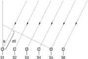
도 4는 빔을 수신하는 복수의 음향 센서들을 예시적으로 도시한다.
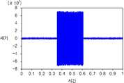
도 5a는 종래 방법에 따른 빔 시계열 신호를 나타내고, 도 5b는 본 발명에 따라 생성되는 빔 시계열 신호를 나타낸다.
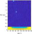
도 6a 내지 6c는 모의 신호로 생성한 2개의 표적 반향음에 대한 빔포밍과 정합필터를 적용하여 표적을 탐지한 결과를 나타낸다.1 schematically illustrates an active sonar device according to an embodiment of the present invention.
Figure 2 shows a flow chart for explaining the operation of an active sonar device according to an embodiment of the present invention.
3 illustrates first to third time-series sensing signals received from first to third acoustic sensors.
4 illustratively shows a plurality of acoustic sensors receiving beams.
5A shows a beam time-series signal according to a conventional method, and FIG. 5B shows a beam time-series signal generated according to the present invention.
6A to 6C show target detection results by applying beamforming and a matched filter to two target echoes generated as simulated signals.
아래에서는 첨부한 도면을 참조하여 본 개시가 속하는 기술 분야에서 통상의 지식을 가진 자가 용이하게 실시할 수 있도록 다양한 실시예들을 상세히 설명한다. 그러나 본 개시의 기술적 사상은 다양한 형태로 변형되어 구현될 수 있으므로 본 명세서에서 설명하는 실시예들로 제한되지 않는다. 본 명세서에 개시된 실시예들을 설명함에 있어서 관련된 공지 기술을 구체적으로 설명하는 것이 본 개시의 기술적 사상의 요지를 흐릴 수 있다고 판단되는 경우 그 공지 기술에 대한 구체적인 설명을 생략한다. 동일하거나 유사한 구성요소는 동일한 참조 번호를 부여하고 이에 대한 중복되는 설명은 생략하기로 한다.Hereinafter, various embodiments will be described in detail so that those skilled in the art can easily implement the present disclosure with reference to the accompanying drawings. However, since the technical spirit of the present disclosure may be implemented in various forms, it is not limited to the embodiments described herein. In describing the embodiments disclosed in this specification, if it is determined that a detailed description of a related known technology may obscure the gist of the technical idea of the present disclosure, a detailed description of the known technology will be omitted. The same or similar components are assigned the same reference numerals, and duplicate descriptions thereof will be omitted.
본 명세서에서 어떤 요소가 다른 요소와 "연결"되어 있다고 기술될 때, 이는 "직접적으로 연결"되어 있는 경우뿐 아니라 그 중간에 다른 요소를 사이에 두고 "간접적으로 연결"되어 있는 경우도 포함한다. 어떤 요소가 다른 요소를 "포함"한다고 할 때, 이는 특별히 반대되는 기재가 없는 한 다른 요소 외에 또 다른 요소를 배제하는 것이 아니라 또 다른 요소를 더 포함할 수 있는 것을 의미한다.In this specification, when an element is described as being “connected” to another element, this includes not only the case of being “directly connected” but also the case of being “indirectly connected” with another element intervening therebetween. When an element "includes" another element, this means that it may further include another element without excluding another element in addition to the other element unless otherwise stated.
일부 실시예들은 기능적인 블록 구성들 및 다양한 처리 단계들로 설명될 수 있다. 이러한 기능 블록들의 일부 또는 전부는 특정 기능을 실행하는 다양한 개수의 하드웨어 및/또는 소프트웨어 구성들로 구현될 수 있다. 예를 들어, 본 개시의 기능 블록들은 하나 이상의 마이크로프로세서들에 의해 구현되거나, 소정의 기능을 위한 회로 구성들에 의해 구현될 수 있다. 본 개시의 기능 블록들은 다양한 프로그래밍 또는 스크립팅 언어로 구현될 수 있다. 본 개시의 기능 블록들은 하나 이상의 프로세서들에서 실행되는 알고리즘으로 구현될 수 있다. 본 개시의 기능 블록이 수행하는 기능은 복수의 기능 블록에 의해 수행되거나, 본 개시에서 복수의 기능 블록이 수행하는 기능들은 하나의 기능 블록에 의해 수행될 수도 있다. 또한, 본 개시는 전자적인 환경 설정, 신호 처리, 및/또는 데이터 처리 등을 위하여 종래 기술을 채용할 수 있다.Some embodiments may be described as functional block structures and various processing steps. Some or all of these functional blocks may be implemented with any number of hardware and/or software components that perform a particular function. For example, functional blocks of the present disclosure may be implemented by one or more microprocessors or circuit configurations for a predetermined function. The functional blocks of this disclosure may be implemented in a variety of programming or scripting languages. The functional blocks of this disclosure may be implemented as an algorithm running on one or more processors. The functions performed by the function blocks of the present disclosure may be performed by a plurality of function blocks, or the functions performed by the plurality of function blocks in the present disclosure may be performed by one function block. In addition, the present disclosure may employ prior art for electronic environment setting, signal processing, and/or data processing.
도 1은 본 발명의 일 실시예에 따른 능동 소나 장치를 개략적으로 도시한다.1 schematically illustrates an active sonar device according to an embodiment of the present invention.
도 1을 참조하면, 능동 소나 장치(100)는 음향 센서 어레이(110), 신호 처리기(120), 빔포밍기(130) 및 탐지기(140)를 포함한다.Referring to FIG. 1 , an
소나(SONAR: Sound Navigation And Ranging)는 수중에 있는 표적의 위치를 탐지하기 위하여 음파를 사용하며, 수중에 존재하는 표적으로부터 방사되는 소음을 탐지하거나, 음파 펄스를 송신하여 임의 거리에 있는 표적으로부터 반사되어 되돌아오는 신호를 수신하고 분석함으로써 표적을 탐지하는 기능을 한다. 소나는 복수의 음향 센서로부터 수신된 음파의 주파수 성분에서 서로 같은 주파수에 해당하는 값을 추출하여 빔형성 기법을 이용하여 표적의 방위와 거리 등을 추정할 수 있다. 능동 소나 장치(100)는 복수의 음향 센서로부터 수신되는 신호로부터 표적의 방위, 거리, 수심 등을 탑지할 수 있다.SONAR (Sound Navigation And Ranging) uses sound waves to detect the location of a target in the water, detects noise emitted from a target in the water, or transmits a sound wave pulse and reflects it from a target at a certain distance It functions to detect the target by receiving and analyzing the signals returned. The sonar extracts values corresponding to the same frequency from frequency components of sound waves received from a plurality of acoustic sensors and estimates the bearing and distance of the target using a beam forming technique. The
음향 센서 어레이(110)는 복수의 음향 센서들을 포함하며, 음향 센서들의 배열은 미리 설계된다. 예를 들면, 음향 센서들은 일렬로 동일한 간격으로 배열될 수 있다. 음향 센서들은 행렬로 배열될 수 있다. 음향 센서들은 방사형으로 배열될 수도 있다.The
음향 센서들이 서로 이격되어 있기 때문에, 표적과 음향 센서들 사이의 거리는 다르게 되며, 표적에서 방사된 신호는 진행 거리의 차에 해당하는 시간차가 발생한다. 음향 센서 어레이(110)의 음향 센서들에서 수신된 신호들은 신호 처리기(120)에 의해 시간차가 보정되고, 빔포밍기(130)에서는 신호 처리기(120)에 의해 처리된 신호들로부터 빔포밍을 수행하여 센서 출력 파워의 합을 극대화시키고, 탐지기(140)에서는 빔포밍기(130)에 의해 형성된 빔을 이용하여 표적의 방위, 거리 등을 탐지할 수 있다.Since the acoustic sensors are spaced apart from each other, the distance between the target and the acoustic sensors is different, and a time difference corresponding to a difference in traveling distance occurs between signals emitted from the target. Signals received from the acoustic sensors of the
빔포밍(Beamforming)은 안테나에서 방사된 에너지가 특정 방향을 따라서 집중적으로 방사되도록 하는 안테나 구현방식으로서, 전방향으로 빔을 방사하고 수신하는 기존 안테나 대신, 해당 방위로만 지향성의 빔을 방사하고 수신함으로써 신호 간섭의 영향을 최소화하여 통신 품질과 시스템 채널 용량을 높일 수 있는 기술이다.Beamforming is an antenna implementation method that allows energy radiated from an antenna to be intensively radiated along a specific direction. Instead of a conventional antenna that radiates and receives beams in all directions, beamforming is radiated and received only in the corresponding direction. It is a technology that can improve communication quality and system channel capacity by minimizing the effect of signal interference.
신호 처리기(120), 빔포밍기(130) 및 탐지기(140)는 적어도 하나의 프로세서에 의해 구현될 수 있다. 능동 소나 장치(100)는 음향 센서 어레이(110), 적어도 하나의 프로세서, 및 메모리를 포함할 수 있으며, 적어도 하나의 프로세서는 신호 처리기(120), 빔포밍기(130) 및 탐지기(140)의 기능을 수행하도록 구성될 수 있다.The
메모리는 컴퓨터에서 판독 가능한 기록 매체로서, RAM(random access memory), ROM(read only memory) 및 디스크 드라이브와 같은 비소멸성 대용량 기록장치(permanent mass storage device)를 포함할 수 있다. 메모리에는 능동 소나 장치(100)를 제어하기 위한 프로그램 코드가 일시적 또는 영구적으로 저장될 수 있다. 메모리에는 음향 센서 어레이(110)를 통해 송신 및 수신할 빔의 빔 방향과 각도 폭을 조정하면서 음향 센서 어레이(110)를 구동하기 위한 코드 또는 명령이 저장될 수 있다. 메모리에는 음향 센서 어레이(110)를 통해 수신되는 신호들로부터 표적을 탐지할 수 있는 알고리즘이 저장될 수 있다.The memory is a computer-readable recording medium, and may include a random access memory (RAM), a read only memory (ROM), and a permanent mass storage device such as a disk drive. A program code for controlling the
프로세서는 기본적인 산술, 로직 및 입출력 연산을 수행함으로써, 컴퓨터 프로그램의 명령을 처리하도록 구성될 수 있다. 명령은 메모리로부터 프로세서에 제공될 수 있다. 예를 들어 프로세서는 메모리와 같은 기록 장치에 저장된 프로그램 코드에 따라 수신되는 명령을 실행하도록 구성될 수 있다.A processor may be configured to process instructions of a computer program by performing basic arithmetic, logic, and input/output operations. Instructions may be provided to the processor from memory. For example, the processor may be configured to execute instructions received according to program codes stored in a recording device such as a memory.
일 실시예에 따르면, 능동 소나 장치(100)의 적어도 하나의 프로세서는 음향 센서 어레이의 음향 센서들에 각각 대응하는 시계열 신호들을 생성하고, 빔 방위를 기초로 음향 센서들 각각의 시간 지연값들을 생성하여 시계열 지연 보상 신호들을 생성하고, 시계열 지연 보상 신호들에 대하여 푸리에 변환을 적용하여 신호 벡터를 생성하고, 신호 벡터를 기초로 조향공분산행렬을 생성하고, 조향공분산행렬에 대하여 WBRCB(Wide Band Robust Capon Beamforming)를 적용하여 산출되는 최적 가중치를 이용하여 빔 신호를 생성하고, 빔 신호에 대하여 푸리에 역변환을 적용하여 빔 시계열 신호를 생성하고, 빔 시계열 신호에 기초하여 표적을 탐지하도록 구성될 수 있다.According to an embodiment, at least one processor of the
프로세서는 적응 빔포밍 방법을 수행하도록 구성될 수 있다. 예를 들어, 프로세서 및 프로세서의 구성요소들은 메모리에 저장되는 운영체제의 코드와 적어도 하나의 프로그램의 코드에 따른 명령(instruction)을 실행하도록 구현될 수 있다.The processor may be configured to perform an adaptive beamforming method. For example, a processor and components of the processor may be implemented to execute instructions according to an operating system code and at least one program code stored in a memory.
음향 센서 어레이(110)는 특정 방향의 빔을 수신 및 방사하는 안테나로서, 미리 설정된 배열로 배치되는 복수의 음향 센서들을 포함한다. 각 음향 센서로부터 수신되는 신호들의 위상과 크기를 조절함으로써 음향 센서 어레이(110)가 특정 방향의 빔을 수신할 수 있다. 본 명세서에서 음향 센서 어레이(110)에 포함되는 음향 센서들의 개수는 n개라고 한다. n은 1 이상의 자연수이다.The
일 예에 따르면 음향 센서 어레이(110)는 음향 신호를 송수신할 수 있는 하나의 음향 센서 어레이일 수 있다. 다른 예에 따르면 음향 센서 어레이(110)는 음파 펄스를 송신하는 송신용 음향 센서 어레이와 음향 신호를 수신하는 수신용 음향 센서 어레이를 포함할 수 있다.According to one example, the
아래에서는 능동 소나 장치(100)가 음향 센서 어레이(110)로부터 수신되는 신호들에 대하여 적응 빔포밍을 수행하는 방법에 대하여 자세히 설명한다.Hereinafter, a method in which the
도 2는 본 발명의 일 실시예에 따른 능동 소나 장치의 동작을 설명하기 위한 순서도를 도시한다. 도 2의 동작은 능동 소나 장치(100) 내의 적어도 하나의 프로세서에 의해 수행될 수 있다.Figure 2 shows a flow chart for explaining the operation of an active sonar device according to an embodiment of the present invention. The operation of FIG. 2 may be performed by at least one processor within the
도 2를 참조하면, 음향 센서 어레이(110)에 포함되는 n개의 음향 센서 각각으로부터 n개의 시계열 센싱 신호(si(t))가 수신될 수 있다(S110). 여기서, i는 1 이상 n 이하의 자연수이다. 제i 시계열 센싱 신호(si(t))는 제i 음향 센서로부터 수신된 신호이다.Referring to FIG. 2 , n time-series sensing signals si (t) may be received from each of the n acoustic sensors included in the acoustic sensor array 110 (S110). Here, i is a natural number greater than or equal to 1 and less than or equal to n. The i th time series sensing signal si (t) is a signal received from the i th acoustic sensor.
n개의 시계열 센싱 신호(si(t))에 기초하여 n개의 시계열 신호(xi(t))가 각각 생성될 수 있다(S120). 일 예에 따르면, n개의 시계열 센싱 신호(si(t))를 보간하여 n개의 시계열 신호(xi(t))가 생성될 수 있다. n개의 시계열 센싱 신호(si(t))는 이산 데이터일 수 있으며, 이를 보간함으로써 연속적인 n개의 시계열 신호(xi(t))가 생성될 수 있다. 다른 예에 따르면, 능동 소나 장치(100)는 이동체에 탑재될 수 있으며, 이동체가 이동할 경우 n개의 음향 센서 각각으로부터 수신되는 n개의 시계열 센싱 신호(si(t))에는 도플러 현상이 반영될 수 있다. 이동체의 이동 방향 및 속도를 기초로 n개의 시계열 센싱 신호(si(t))를 보정함으로써, n개의 시계열 신호(xi(t))가 생성될 수 있다.Based on the n time-series sensing signals si (t), n time-series signals xi (t) may be respectively generated (S120). According to an example, n time series signals xi (t) may be generated by interpolating n time series sensing signals si (t). The n time series sensing signals si (t) may be discrete data, and n consecutive time series signals xi (t) may be generated by interpolating the discrete data. According to another example, the
빔 방위(θ)를 기초로 n개의 음향 센서 각각의 시간 지연값들(τi,θ)을 생성하고, 생성된 n개의 시간 지연값(τi,θ)을 이용하여 n개의 시계열 지연 보상 신호(xi(t-τi,θ), i ∈ {1, ..., n})가 생성될 수 있다(S130). xi(t)는 n개의 시계열 신호 중 제i 시계열 신호이고, τi,θ는 빔 방위(θ)를 기초로 산출되는 n개의 음향 센서 중 제i 음향 센서의 시간 지연값이며, xi(t-τi,θ)는 n개의 시계열 지연 보상 신호 중 제i 시계열 지연 보상 신호이다.Time delay values (τi, θ ) of each of the n acoustic sensors are generated based on the beam orientation (θ), and n time-series delay compensation signals are generated using the n time delay values (τi, θ ). (xi (t-τi, θ ), i ∈ {1, ..., n}) may be generated (S130). xi (t) is the i-th time-series signal among n time-series signals, τi,θ is the time delay value of the i-th acoustic sensor among the n acoustic sensors calculated based on the beam orientation (θ), and xi ( t−τi,θ ) is an i th time series delay compensation signal among n time series delay compensation signals.
도 3은 제1 내지 제3 음향 센서로부터 수신되는 제1 내지 제3 시계열 센싱 신호(s1(t), s2(t), s3(t))가 예시적으로 도시된다. 표적으로부터 방사된 펄스 신호는 시차를 두고 제1 내지 제3 음향 센서에 수신된다.3 illustrates first to third time-series sensing signals s1 (t), s2 (t), and s3 (t) received from first to third acoustic sensors. Pulse signals emitted from the target are received by the first to third acoustic sensors with a time difference.
도 4는 일렬로 배열되는 제1 내지 제6 음향 센서들(S1-S6)을 예시적으로 도시한다. 제1 내지 제6 음향 센서들(S1-S6)은 빔 방위(θ)로부터 음파 신호를 수신할 수 있다. 도 4에 도시된 바와 같이, 빔 방위(θ)에 따라 제6 음향 센서(S6)에 음파 신호가 가장 먼저 도달하고, 제1 음향 센서(S1)에 음파 신호가 가장 늦게 도달한다. 예컨대, 제1 음향 센서(S1)와 제5 음향 센서(S5) 사이에 빔 경로차(d5)가 존재하며, 이 빔 경로차(d5)를 음파 신호의 속도로 나눈 값은 제5 음향 센서(S5)의 제1 음향 센서(S1)에 대한 지연 신호값일 수 있다. 본 예에서는 빔 방위(θ)가 양수이므로, 제5 음향 센서(S5)의 제1 음향 센서(S1)에 대한 지연 신호값은 음수이다. 이러한 방식으로, 빔 방위(θ)에 기초하여 음향 센서들 각각의 지연 신호값들(τi,θ)이 산출될 수 있다.FIG. 4 illustratively illustrates first to sixth acoustic sensors S1 to S6 arranged in a line. The first to sixth acoustic sensors S1 to S6 may receive sound wave signals from the beam direction θ. As shown in FIG. 4 , according to the beam orientation θ, the sound wave signal reaches the sixth acoustic sensor S6 first, and the first acoustic sensor S1 arrives last. For example, there is a beam path difference d5 between the first acoustic sensor S1 and the fifth acoustic sensor S5, and the value obtained by dividing the beam path difference d5 by the speed of the sound wave signal is the fifth acoustic sensor ( It may be a delay signal value for the first acoustic sensor S1 of S5). In this example, since the beam direction θ is a positive number, the delay signal value for the first acoustic sensor S1 of the fifth acoustic sensor S5 is a negative number. In this way, delay signal values τi, θ of each of the acoustic sensors can be calculated based on the beam orientation θ.
다시 도 2를 참조하면, n개의 시계열 신호(xi(t))와 n개의 시간 지연값(τi,θ)을 이용하여 n개의 시계열 지연 보상 신호(xi(t-τi,θ))가 생성될 수 있다. 시계열 지연 보상 신호(xi(t-τi,θ))는 시계열 신호(xi(t))를 시간 지연값(τi,θ)만큼 보상한 신호일 수 있다.Referring to FIG. 2 again, n time series delay compensation signals (xi (t−τi, θ )) using n time series signals (xi (t)) and n time delay values (τi , θ ) ) can be created. The time series delay compensation signal xi (t-τi, θ ) may be a signal obtained by compensating the time series signal xi (t) by a time delay value (τi, θ ).
다른 실시예에 따르면, n개의 시계열 센싱 신호(si(t))에 n개의 시간 지연값(τi,θ)을 보상하여, n개의 시계열 센싱 지연 보상 신호(si(t-τi,θ))를 생성한 후, n개의 시계열 센싱 지연 보상 신호(si(t-τi,θ))를 기초로 n개의 시계열 지연 보상 신호(xi(t-τi,θ))가 생성될 수도 있다.According to another embodiment, by compensating for n time-series sensing signals si (t) with n time delay values τi, θ , the n time-series sensing delay compensation signals si (t-τi, After generatingθ )), n time series delay compensation signals (xi (t-τi, θ )) are generated based on n time series sensing delay compensation signals (si (t-τi, θ )). It could be.
n개의 시계열 지연 보상 신호(xi(t-τi,θ))에 대하여 푸리에 변환을 적용하여 신호 벡터(Yf,θ)가 생성될 수 있다(S140). 신호 벡터(Yf,θ)는 특정 주파수(f)와 특정 빔 방위(θ)에 대한 신호 벡터로서, n개의 원소를 가질 수 있으며, n개의 원소 각각은 n개의 시계열 지연 보상 신호(xi(t-τi,θ)) 각각을 푸리에 변환한 결과에 대응할 수 있다.A signal vector (Yf, θ ) may be generated by applying a Fourier transform to n time-series delay compensation signals (xi (t-τi, θ )) (S140). The signal vector (Yf, θ ) is a signal vector for a specific frequency (f) and a specific beam orientation (θ), and may have n elements, each of which is n time series delay compensation signals (xi ( t-τi, θ )) may correspond to a result of Fourier transform.
신호 벡터(Yf,θ)에 기초하여 조향공분산행렬(steered covariance matrix)(Rfl,fh(θ))이 생성될 수 있다(S150).A steering covariance matrix (Rfl,fh (θ)) may be generated based on the signal vector (Yf,θ ) (S150).
조향공분산행렬(Rfl,fh(θ))은 아래의 수식 1에 따라 산출될 수 있다.The steering covariance matrix (Rfl,fh (θ)) can be calculated according to
[수식 1][Formula 1]

여기서, Yf,θ는 특정 주파수(f)와 특정 빔 방위(θ)에 대한 신호 벡터이고, Rfl,fh(θ)는 특정 빔 방위(θ)에 대한 조향공분산행렬이고, fl과 fh는 각각 빔포밍 후 시계열 변환을 위해 설정한 대역의 최소 주파수와 최대 주파수일 수 있다.Here, Yf,θ is a signal vector for a specific frequency (f) and a specific beam orientation (θ), Rfl,fh (θ) is a steering covariance matrix for a specific beam orientation (θ), fl and fh may be a minimum frequency and a maximum frequency of a band set for time series conversion after beamforming, respectively.
수식 1에 의해 산출된 조향공분산행렬(Rfl,fh(θ))을 WBRCB(Wide Band Robust Capon Beamforming)에 적용하여 산출되는 최적 가중치(
최적 가중치(
[수식 2][Formula 2]

여기서, ε는 불일치 파라미터이고,

[수식 3][Formula 3]

여기서 λ는 대각 로딩값이며, 수식 2의 제한 조건, 즉, ∥


이렇게 산출된 최적 가중치(

빔 신호(Bθ)에 대하여 푸리에 역변환을 적용하여 빔 시계열 신호(b(t))가 생성될 수 있다(S170). 전주파수 빈에 대해 동일한 값의 가중치 벡터를 적용하므로, 빔 시계열 신호의 위상이 그대로 유지될 수 있으며, 정합필터 등의 능동 신호 처리가 가능하게 된다.A beam time-series signal b(t) may be generated by applying an inverse Fourier transform to the beam signal Bθ (S170). Since the weight vector of the same value is applied to all frequency bins, the phase of the beam time series signal can be maintained as it is, and active signal processing such as a matched filter can be performed.
빔 시계열 신호(b(t))에 기초하여, 표적이 탐지될 수 있다(S180). 빔 시계열 신호(b(t))을 이용하여 표적을 탐지하는 다양한 방법 및 알고리즘이 사용될 수 있으며, 이러한 방법과 알고리즘은 본 발명을 한정하지 않는다.Based on the beam time series signal b(t), a target may be detected (S180). Various methods and algorithms for detecting a target using the beam time series signal b(t) may be used, and these methods and algorithms do not limit the present invention.
본 발명은 광대역 적응 빔포밍 방법 중 하나인 WBRCB(Wide Band Robust Capon Beamforming) 방법을 적용하여 적응 빔포밍 후에 다시 빔 신호를 빔 시계열 신호로 변환할 수 있다. WBRCB 방법은 불일치에 강인한 RCB(Robust Capon Beamforming) 방법을 광대역으로 확장한 것으로서, 특정 대역에 대해 최적의 가중치를 산출하는 방법이다.In the present invention, a beam signal may be converted into a beam time-series signal again after adaptive beamforming by applying a Wide Band Robust Capon Beamforming (WBRCB) method, which is one of wideband adaptive beamforming methods. The WBRCB method is a broadband extension of a Robust Capon Beamforming (RCB) method that is robust against mismatch, and is a method of calculating an optimal weight for a specific band.
빔포밍 후 빔 시계열 신호로 변환하기 위해 최소 주파수(fl)와 최대 주파수(fh)가 전체 대역으로 설정될 수 있다. WBRCB 방법에서 사용하는 조향공분산행렬(Rfl,fh(θ))은 다음의 수식 4와 같다.After beamforming, a minimum frequency (fl ) and a maximum frequency (fh ) may be set to the entire band in order to be converted into a beam time series signal. The steering covariance matrix (Rfl,fh (θ)) used in the WBRCB method is shown in
[수식 4][Formula 4]

여기서 Rf는 주파수(f)에 대한 교차스펙트럼밀도 행렬이고, Tf,θ는 센서별 시간 지연을 보상하기 위한 대각 행렬이다.Here, Rf is a cross-spectral density matrix for frequency (f), and Tf,θ is a diagonal matrix for compensating the time delay for each sensor.
n개의 음향 센서에 각각 대응하는 n개의 시계열 신호(xi(t)) 각각에 대하여 푸리에 변환을 적용하여, 특정 주파수(f)에 대한 신호 벡터(Xf)가 생성될 수 있다. 신호 벡터(Xf)의 각 요소는 n개의 시계열 신호(xi(t)) 각각의 푸리에 변환 결과이다.A signal vector Xf for a specific frequency f may be generated by applying a Fourier transform to each of the n time-series signals xi (t) corresponding to the n acoustic sensors. Each element of the signal vector (Xf ) is a Fourier transform result of each of n time series signals (xi (t)).
교차스펙트럼밀도 행렬(Rf)은 신호 벡터(Xf)에 대한 외적 평균인 E[XfXfH]를 통해 산출될 수 있다. Tf,θ는 대각 행렬로 f와 θ에 대한 지향 벡터 성분으로 아래의 수식 5와 같이 정의될 수 있다.The cross-spectral density matrix (Rf ) can be calculated through E[Xf XfH ], which is the cross-product average of the signal vector (Xf ). Tf,θ may be defined as
[수식 5][Formula 5]

여기서, τi,θ는 제i 음향 센서에서 빔 방위(θ)에 대한 시간 지연값이다. 교차스펙트럼밀도 행렬(Rf)은 현재 프레임에 대한 신호 벡터(Xf)를 사용하여 XfXfH로 근사화될 수 있다. 이를 수식 4에 적용하면, Tf,θRfTf,θH는 Tf,θXfXfHTf,θH로 표현될 수 있으며, 벡터(Tf,θXf(θ))는 현재 수신한 신호에 지향 벡터 성분을 보정한 벡터로서, 음향 센서 별로 수신한 시계열 신호에 대해 음향 센서 별 시간 지연을 위상 천이 형태로 제거한 벡터이다.Here, τi, θ is a time delay value for the beam orientation θ in the ith acoustic sensor. The cross-spectral density matrix (Rf ) can be approximated as Xf XfH using the signal vector (Xf ) for the current frame. Applying this to
전술한 바와 같이, 현재 프레임에 대한 신호 벡터(Xf)는 현재 프레임에 대해 음향 센서 별 시계열 신호에 대해 푸리에 변환을 적용하여 산출될 수 있다. 신호가 일정한 크기와 주파수로 입력되는 상황에서는 입력 신호를 주파수 영역으로 변환한 후 위상을 천이하는 방식으로 음향 센서 별 시간 지연을 보상할 수 있다. 그러나, 능동 소나와 같이 입력 신호의 진폭이 펄스 형태에 따라 크게 바뀌거나 펄스의 주파수가 프레임 별로 달라지는 경우에는 위상 천이를 적용하기 어렵다는 문제를 갖는다.As described above, the signal vector (Xf ) for the current frame may be calculated by applying Fourier transform to the time-series signal for each acoustic sensor for the current frame. In a situation where a signal is input with a constant magnitude and frequency, a time delay for each acoustic sensor may be compensated for by converting the input signal into a frequency domain and then shifting the phase. However, it is difficult to apply phase shift when the amplitude of an input signal greatly varies according to a pulse shape or the frequency of a pulse varies for each frame, such as in active sonar.
본 발명에서는 이러한 문제를 해결하기 위해 시계열 데이터로 빔포밍을 수행하는 지연합 방법을 이용한다. 우선 지연합 방법은 음향 센서 별로 빔 방위(θ)에 따른 시간 지연값(τi,θ)을 계산하여 해당 샘플의 값을 찾고, 이를 더하는 방법이다. 지연합에 사용되는 샘플이 모두 동일한 시간대의 정보가 아니기 때문에, 진폭과 주파수 변이에 대응되는 강점을 갖는다. 시간 지연값(τi,θ)을 고려한 제i 음향 센서의 시계열 신호는 xi(t-τi,θ)로 표현될 수 있으며, τi,θ는 제i 음향 센서와 빔 방위(θ)에 대한 시간 지연값이다.In the present invention, in order to solve this problem, a delayed coalescence method of performing beamforming with time-series data is used. First, the delay association method is a method of calculating a time delay value (τi, θ ) according to a beam orientation (θ) for each acoustic sensor, finding a value of a corresponding sample, and adding the values. Since the samples used for delay association are not all information of the same time period, it has strength corresponding to amplitude and frequency shift. The time series signal of the ith acoustic sensor considering the time delay value (τi, θ ) can be expressed as xi (t-τi, θ ), where τi, θ is the ith acoustic sensor and the beam orientation (θ) is the time delay value for
본 발명에서는 현재 프레임에 대해 시간 지연값을 보상한 음향 센서 별 시계열 신호(xi(t-τi,θ))를 보간을 통해 샘플 별로 획득할 수 있고, 각 신호에 대해 푸리에 변환을 적용하여 신호 벡터(Yf,θ)를 생성할 수 있다. 신호 벡터(Yf,θ)는 특정 주파수(f)와 특정 빔 방위(θ)에 대해 시간 지연이 보상된 신호(Tf,θXf)에 대응된다. 본 발명에서 사용하는 조향공분산행렬(Rfl,fh(θ))은 수식 1과 같다.In the present invention, the time-series signal (xi (t-τi, θ )) for each acoustic sensor for which the time delay value is compensated for for the current frame can be obtained for each sample through interpolation, and Fourier transform is applied to each signal A signal vector (Yf, θ ) can be generated. The signal vector (Yf, θ ) corresponds to the time delay-compensated signal (Tf, θ Xf ) for a specific frequency (f) and a specific beam orientation (θ). The steering covariance matrix (Rfl,fh (θ)) used in the present invention is as shown in
본 발명에 따르면, 수식 1의 조향공분산행렬(Rfl,fh(θ))을 WBRCB에 적용하여 전대역에 대한 최적 가중치(


본 발명 따르면, 빔 신호(Bθ)는
도 3을 참조하면, 종래의 방법에서는 센싱 데이터(SA)를 이용하여 조향공분산행렬(Rfl,fh(θ))의 계산에 사용되는 신호 벡터(Xf)가 생성된다. 그러나, 본 발명에 따르면 센싱 데이터(SB)를 이용하여 신호 벡터(Yf,θ)가 생성된다. 도 3에 도시된 바와 같이, 종래의 신호 벡터(Xf)는 프레임에 따라 펄스 신호의 일부만 선택된다는 문제가 발생하지만, 본 발명의 신호 벡터(Yf,θ)는 해당 빔 방위(θ)에서 센서 신호의 펄스가 모두 선택되어 빔포밍에 이용된다.Referring to FIG. 3 , in the conventional method, a signal vector Xf used for calculating a steering covariance matrix Rfl,fh (θ) is generated using sensing data SA . However, according to the present invention, the signal vector (Yf, θ ) is generated using the sensing data (SB ). As shown in FIG. 3, the conventional signal vector (Xf ) has a problem that only a part of the pulse signal is selected according to the frame, but the signal vector (Yf, θ ) of the present invention is All pulses of the sensor signal are selected and used for beamforming.
도 5a는 종래 방법에 따른 빔 시계열 신호를 나타내고, 도 5b는 본 발명에 따라 생성되는 빔 시계열 신호를 나타낸다. 도 5a와 도 5b는 모두 펄스에 대한 빔포밍 결과로 펄스가 존재하는 빔 시계열 신호를 나타낸다. 도 5a에 도시된 바와 같이, 종래 방법에서는 프레임 별로 센서 신호를 선택하기 때문에 불필요한 결과(N)가 생성된다. 반면, 도 5b에 도시된 바와 같이, 본 발명의 발명에 따르면, 펄스의 형태가 그대로 유지되는 빔 시계열 신호가 생성된다.5A shows a beam time-series signal according to a conventional method, and FIG. 5B shows a beam time-series signal generated according to the present invention. 5A and 5B both show a beam time-series signal in which a pulse exists as a result of beamforming on the pulse. As shown in FIG. 5A, in the conventional method, since a sensor signal is selected for each frame, an unnecessary result (N) is generated. On the other hand, as shown in FIG. 5B, according to the present invention, a beam time-series signal in which the shape of a pulse is maintained is generated.
도 6a 내지 6c는 모의 신호로 생성한 2개의 표적 반향음에 대한 빔포밍과 정합필터를 적용하여 표적을 탐지한 결과를 나타낸다.6A to 6C show target detection results by applying beamforming and a matched filter to two target echoes generated as simulated signals.
도 6a는 종래의 지연합 빔포밍 방법을 이용한 표적 탐지 결과이고, 도 6b는 종래 WBRCB 방법을 이용한 표적 탐지 결과이고, 도 6c는 본 발명의 적응 빔포밍 방법을 이용한 표적 탐지 결과이다.6A is a target detection result using the conventional delayed linkage beamforming method, FIG. 6B is a target detection result using the conventional WBRCB method, and FIG. 6C is a target detection result using the adaptive beamforming method of the present invention.
도 6a 내지 도 6c를 통해 쉽게 알 수 있다시피, 본 발명의 적응 빔포밍 방법에 따른 표적 탐지 결과(도 6c)는 종래 지연합 빔포밍 방법에 따른 표적 탐지 결과(도 6a)와 종래 WBRCB 방법에 따른 표적 탐지 결과(도 6b)보다 더 정확하고 선명하다.6a to 6c, the target detection result according to the adaptive beamforming method of the present invention (Fig. 6c) is different from the target detection result according to the conventional delayed linkage beamforming method (Fig. 6a) and the conventional WBRCB method. It is more accurate and clearer than the target detection result according to (Fig. 6b).
본 명세서에서 설명되는 다양한 실시예들은 예시적이며, 서로 구별되어 독립적으로 실시되어야 하는 것은 아니다. 본 명세서에서 설명된 실시예들은 서로 조합된 형태로 실시될 수 있다.The various embodiments described in this specification are illustrative, and are not to be discriminated from and independently implemented. The embodiments described in this specification may be implemented in a combination with each other.
이상 설명된 다양한 실시예들은 컴퓨터 상에서 다양한 구성요소를 통하여 실행될 수 있는 컴퓨터 프로그램의 형태로 구현될 수 있으며, 이와 같은 컴퓨터 프로그램은 컴퓨터로 판독 가능한 매체에 기록될 수 있다. 이때, 매체는 컴퓨터로 실행 가능한 프로그램을 계속 저장하거나, 실행 또는 다운로드를 위해 임시 저장하는 것일 수도 있다. 또한, 매체는 단일 또는 수개 하드웨어가 결합된 형태의 다양한 기록수단 또는 저장수단일 수 있는데, 어떤 컴퓨터 시스템에 직접 접속되는 매체에 한정되지 않고, 네트워크 상에 분산 존재하는 것일 수도 있다. 매체의 예시로는, 하드 디스크, 플로피 디스크 및 자기 테이프와 같은 자기 매체, CD-ROM 및 DVD와 같은 광기록 매체, 플롭티컬 디스크(floptical disk)와 같은 자기-광 매체(magneto-optical medium), 및 ROM, RAM, 플래시 메모리 등을 포함하여 프로그램 명령어가 저장되도록 구성된 것이 있을 수 있다. 또한, 다른 매체의 예시로, 애플리케이션을 유통하는 앱 스토어나 기타 다양한 소프트웨어를 공급 내지 유통하는 사이트, 서버 등에서 관리하는 기록매체 내지 저장매체도 들 수 있다.Various embodiments described above may be implemented in the form of a computer program that can be executed on a computer through various components, and such a computer program may be recorded on a computer-readable medium. In this case, the medium may continuously store a program executable by a computer or temporarily store the program for execution or download. In addition, the medium may be various recording means or storage means in the form of a single or combined hardware, but is not limited to a medium directly connected to a certain computer system, and may be distributed on a network. Examples of the medium include magnetic media such as hard disks, floppy disks and magnetic tapes, optical recording media such as CD-ROM and DVD, magneto-optical media such as floptical disks, and ROM, RAM, flash memory, etc. configured to store program instructions. In addition, examples of other media include recording media or storage media managed by an app store that distributes applications, a site that supplies or distributes various other software, and a server.
본 명세서에서, "부", "모듈" 등은 프로세서 또는 회로와 같은 하드웨어 구성(hardware component), 및/또는 프로세서와 같은 하드웨어 구성에 의해 실행되는 소프트웨어 구성(software component)일 수 있다. 예를 들면, "부", "모듈" 등은 소프트웨어 구성 요소들, 객체 지향 소프트웨어 구성 요소들, 클래스 구성 요소들 및 태스크 구성 요소들과 같은 구성 요소들과, 프로세스들, 함수들, 속성들, 프로시저들, 서브루틴들, 프로그램 코드의 세그먼트들, 드라이버들, 펌웨어, 마이크로 코드, 회로, 데이터, 데이터베이스, 데이터 구조들, 테이블들, 어레이들 및 변수들에 의해 구현될 수 있다.In this specification, “unit”, “module”, etc. may be a hardware component such as a processor or a circuit, and/or a software component executed by a hardware component such as a processor. For example, "unit", "module", etc. may refer to components such as software components, object-oriented software components, class components, and task components, processes, functions, properties, It can be implemented by procedures, subroutines, segments of program code, drivers, firmware, microcode, circuitry, data, databases, data structures, tables, arrays and variables.
전술한 본 발명의 설명은 예시를 위한 것이며, 본 발명이 속하는 기술분야의 통상의 지식을 가진 자는 본 발명의 기술적 사상이나 필수적인 특징을 변경하지 않고서 다른 구체적인 형태로 쉽게 변형이 가능하다는 것을 이해할 수 있을 것이다. 그러므로 이상에서 기술한 실시예들은 모든 면에서 예시적인 것이며 한정적이 아닌 것으로 이해해야만 한다. 예를 들어, 단일형으로 설명되어 있는 각 구성 요소는 분산되어 실시될 수도 있으며, 마찬가지로 분산된 것으로 설명되어 있는 구성 요소들도 결합된 형태로 실시될 수 있다.The above description of the present invention is for illustrative purposes, and those skilled in the art can understand that it can be easily modified into other specific forms without changing the technical spirit or essential features of the present invention. will be. Therefore, the embodiments described above should be understood as illustrative in all respects and not limiting. For example, each component described as a single type may be implemented in a distributed manner, and similarly, components described as distributed may be implemented in a combined form.
본 발명의 범위는 상기 상세한 설명보다는 후술하는 특허청구범위에 의하여 나타내어지며, 특허청구범위의 의미 및 범위 그리고 그 균등 개념으로부터 도출되는 모든 변경 또는 변형된 형태가 본 발명의 범위에 포함되는 것으로 해석되어야 한다.The scope of the present invention is indicated by the following claims rather than the detailed description above, and all changes or modifications derived from the meaning and scope of the claims and equivalent concepts should be construed as being included in the scope of the present invention. do.
Claims (10)
Translated fromKorean빔 방위를 기초로 상기 복수의 음향 센서 각각의 시간 지연값들을 생성하여 복수의 시계열 지연 보상 신호를 생성하는 단계;
상기 복수의 시계열 지연 보상 신호에 대하여 푸리에 변환을 적용하여 신호 벡터를 생성하는 단계;
상기 신호 벡터를 기초로 조향공분산행렬을 생성하는 단계;
상기 조향공분산행렬에 대하여 WBRCB(Wide Band Robust Capon Beamforming)를 적용하여 산출되는 최적 가중치를 이용하여 빔 신호를 생성하는 단계; 및
상기 빔 신호에 대하여 푸리에 역변환을 적용하여 빔 시계열 신호를 생성하는 단계를 포함하는 적응 빔포밍 방법.generating a plurality of time-series signals respectively corresponding to a plurality of acoustic sensors;
generating a plurality of time-series delay compensation signals by generating time delay values of each of the plurality of acoustic sensors based on a beam orientation;
generating a signal vector by applying a Fourier transform to the plurality of time series delay compensation signals;
generating a steering covariance matrix based on the signal vector;
generating a beam signal using an optimal weight calculated by applying Wide Band Robust Capon Beamforming (WBRCB) to the steering covariance matrix; and
and generating a beam time-series signal by applying an inverse Fourier transform to the beam signal.
상기 복수의 시계열 신호를 생성하는 단계는,
상기 복수의 음향 센서로부터 복수의 시계열 센싱 신호를 각각 수신하는 단계; 및
상기 복수의 시계열 센싱 신호에 기초하여 상기 복수의 시계열 신호를 생성하는 단계를 포함하는 적응 빔포밍 방법.According to claim 1,
Generating the plurality of time series signals,
Receiving a plurality of time-series sensing signals from the plurality of acoustic sensors, respectively; and
and generating the plurality of time-series signals based on the plurality of time-series sensing signals.
상기 복수의 시계열 지연 보상 신호는 xi(t-τi,θ)(i ∈ {1, ..., n})에 따라 생성되고,
여기서, xi(t)는 상기 복수의 시계열 신호 중 제i 시계열 신호이고, τi,θ는 빔 방위(θ)를 기초로 산출되는 상기 복수의 음향 센서 중 제i 음향 센서의 시간 지연값이고, n은 상기 복수의 음향 센서의 개수인 적응 빔포밍 방법.According to claim 1,
The plurality of time series delay compensation signals are generated according to xi (t-τi, θ ) (i ∈ {1, ..., n}),
Here, xi (t) is an i-th time-series signal among the plurality of time-series signals, τi,θ is a time delay value of an ith acoustic sensor among the plurality of acoustic sensors calculated based on the beam orientation (θ), and , n is the number of the plurality of acoustic sensors.
상기 신호 벡터는 상기 복수의 시계열 지연 보상 신호 각각을 푸리에 변환한 결과에 대응하는 복수의 요소는 갖는 적응 빔포밍 방법.According to claim 1,
The signal vector has a plurality of elements corresponding to a result of Fourier transforming each of the plurality of time-series delay compensation signals.
상기 조향공분산행렬은

여기서, Yf,θ는 상기 신호 벡터이고, Rfl,fh(θ)는 상기 조향공분산행렬이고, θ는 상기 빔 방위이고, fl과 fh는 각각 빔포밍 후 시계열 변환을 위해 설정한 대역의 최소 주파수와 최대 주파수인 적응 빔포밍 방법.According to claim 1,
The steering covariance matrix is
Here, Yf,θ is the signal vector, Rfl,fh (θ) is the steering covariance matrix, θ is the beam orientation, and fl and fh are bands set for time-series conversion after beamforming, respectively. An adaptive beamforming method where the minimum and maximum frequencies of .
상기 최적 가중치는

여기서, ε는 불일치 파라미터이고,


The optimal weight is
where ε is the disparity parameter,
상기 최적 가중치(


여기서 λ는 대각 로딩값인 적응 빔포밍 방법.According to claim 6,
The optimal weight (
Here, λ is an adaptive beamforming method that is a diagonal loading value.
상기 빔 신호는

The beam signal is
상기 복수의 음향 센서에 각각 대응하는 복수의 시계열 신호를 생성하고, 빔 방위를 기초로 상기 복수의 음향 센서 각각의 시간 지연값들을 생성하여 복수의 시계열 지연 보상 신호를 생성하고, 상기 복수의 시계열 지연 보상 신호에 대하여 푸리에 변환을 적용하여 신호 벡터를 생성하고, 상기 신호 벡터를 기초로 조향공분산행렬을 생성하고, 상기 조향공분산행렬에 대하여 WBRCB(Wide Band Robust Capon Beamforming)를 적용하여 산출되는 최적 가중치를 이용하여 빔 신호를 생성하고, 상기 빔 신호에 대하여 푸리에 역변환을 적용하여 빔 시계열 신호를 생성하고, 상기 빔 시계열 신호에 기초하여 표적을 탐지하도록 구성되는 적어도 하나의 프로세서를 포함하는 적응 빔포밍을 이용한 능동 소나 장치.
an acoustic sensor array including a plurality of acoustic sensors; and
generating a plurality of time-series signals respectively corresponding to the plurality of acoustic sensors, generating a plurality of time-series delay compensation signals by generating time delay values of each of the plurality of acoustic sensors based on a beam orientation, and generating a plurality of time-series delay compensation signals; A signal vector is generated by applying a Fourier transform to the compensation signal, a steering covariance matrix is generated based on the signal vector, and an optimal weight calculated by applying WBRCB (Wide Band Robust Capon Beamforming) to the steering covariance matrix is calculated. Adaptive beamforming including at least one processor configured to generate a beam signal, generate a beam time-series signal by applying an inverse Fourier transform to the beam signal, and detect a target based on the beam time-series signal. Active sonar device.
Priority Applications (1)
| Application Number | Priority Date | Filing Date | Title |
|---|---|---|---|
| KR1020210000843AKR102483990B1 (en) | 2021-01-05 | 2021-01-05 | Adaptive beamforming method and active sonar using the same |
Applications Claiming Priority (1)
| Application Number | Priority Date | Filing Date | Title |
|---|---|---|---|
| KR1020210000843AKR102483990B1 (en) | 2021-01-05 | 2021-01-05 | Adaptive beamforming method and active sonar using the same |
Publications (2)
| Publication Number | Publication Date |
|---|---|
| KR20220098933A KR20220098933A (en) | 2022-07-12 |
| KR102483990B1true KR102483990B1 (en) | 2023-01-04 |
Family
ID=82420070
Family Applications (1)
| Application Number | Title | Priority Date | Filing Date |
|---|---|---|---|
| KR1020210000843AActiveKR102483990B1 (en) | 2021-01-05 | 2021-01-05 | Adaptive beamforming method and active sonar using the same |
Country Status (1)
| Country | Link |
|---|---|
| KR (1) | KR102483990B1 (en) |
Cited By (1)
| Publication number | Priority date | Publication date | Assignee | Title |
|---|---|---|---|---|
| KR102667103B1 (en)* | 2023-12-04 | 2024-05-20 | 한화시스템 주식회사 | Underwater acoustic signal synthesis method and apparatus |
Families Citing this family (1)
| Publication number | Priority date | Publication date | Assignee | Title |
|---|---|---|---|---|
| KR102819220B1 (en)* | 2022-07-21 | 2025-06-11 | 엘아이지넥스원 주식회사 | Method and Apparatus for Detecting Targets in Underwater Vehicles |
Citations (3)
| Publication number | Priority date | Publication date | Assignee | Title |
|---|---|---|---|---|
| KR101094786B1 (en) | 2010-07-05 | 2011-12-16 | 국방과학연구소 | Heterogeneous Frequency Beamforming Method and Sonar System Using the Same |
| KR101239604B1 (en) | 2004-09-23 | 2013-03-05 | 하만 베커 오토모티브 시스템즈 게엠베하 | Multi-channel adaptive speech signal processing with noise reduction |
| KR101715903B1 (en) | 2015-10-27 | 2017-03-13 | 국방과학연구소 | Method and Apparatus for robust detection of target bearings for triplet sensor arrays against to noise signals, arrangement distortions, and angle errors |
Family Cites Families (2)
| Publication number | Priority date | Publication date | Assignee | Title |
|---|---|---|---|---|
| US20040138876A1 (en)* | 2003-01-10 | 2004-07-15 | Nokia Corporation | Method and apparatus for artificial bandwidth expansion in speech processing |
| KR102159631B1 (en)* | 2018-11-21 | 2020-09-24 | 에스티엑스엔진 주식회사 | Method for processing the signal for an adaptive beamformer using sub-band steering covariance matrix |
- 2021
- 2021-01-05KRKR1020210000843Apatent/KR102483990B1/enactiveActive
Patent Citations (3)
| Publication number | Priority date | Publication date | Assignee | Title |
|---|---|---|---|---|
| KR101239604B1 (en) | 2004-09-23 | 2013-03-05 | 하만 베커 오토모티브 시스템즈 게엠베하 | Multi-channel adaptive speech signal processing with noise reduction |
| KR101094786B1 (en) | 2010-07-05 | 2011-12-16 | 국방과학연구소 | Heterogeneous Frequency Beamforming Method and Sonar System Using the Same |
| KR101715903B1 (en) | 2015-10-27 | 2017-03-13 | 국방과학연구소 | Method and Apparatus for robust detection of target bearings for triplet sensor arrays against to noise signals, arrangement distortions, and angle errors |
Cited By (1)
| Publication number | Priority date | Publication date | Assignee | Title |
|---|---|---|---|---|
| KR102667103B1 (en)* | 2023-12-04 | 2024-05-20 | 한화시스템 주식회사 | Underwater acoustic signal synthesis method and apparatus |
Also Published As
| Publication number | Publication date |
|---|---|
| KR20220098933A (en) | 2022-07-12 |
Similar Documents
| Publication | Publication Date | Title |
|---|---|---|
| US10690743B2 (en) | Doppler measurements to resolve angle of arrival ambiguity of wide aperture radar | |
| US8692810B2 (en) | Method for determining the location of impacts by acoustic imaging | |
| JP5701106B2 (en) | Radar device and method of calculating angle of arrival of radar device | |
| KR102483990B1 (en) | Adaptive beamforming method and active sonar using the same | |
| JP6362262B2 (en) | Angle estimation apparatus and angle estimation method | |
| JP3367462B2 (en) | Active sonar and target detection method thereof | |
| US11125871B2 (en) | Azimuth estimation device and method | |
| JP2020193881A (en) | Azimuth estimating device, azimuth estimating method, and program | |
| JP6920032B2 (en) | Radar device and angle detection method | |
| JP2010127771A (en) | Synthetic aperture sonar, and method and program for correcting phase error of synthetic aperture sonar | |
| EP2317335B1 (en) | Improved beamforming method for analysing signals received by a transducer arrray, and relative detection system | |
| JP7248454B2 (en) | Radar device and correction value calculation method | |
| JP7154494B2 (en) | Direction-of-arrival estimation device and direction-of-arrival estimation method | |
| JP3396798B2 (en) | Target position localization method | |
| WO2017164365A1 (en) | Target detection system, method, and program | |
| US11633172B2 (en) | Synthetic transmit focusing ultrasound system with speed of sound aberration correction | |
| JP2001194451A (en) | Radar equipment | |
| US10560192B2 (en) | Technique for focusing waves on moving objects | |
| NO336797B1 (en) | Signal processing method for a towed linear antenna | |
| JPH10246778A (en) | Target detection and tracking device | |
| JP2011013182A (en) | Target detector and method of detecting target | |
| TWI704365B (en) | Detecting device and detecting method thereof | |
| KR101052050B1 (en) | Method to improve detection rate of moving target by coherently combining multiple radars and radar system to which the method is applied | |
| KR102357309B1 (en) | Method for processing the signal for an adaptive beamformer using size reduction of covariance matrix | |
| JP2021120647A (en) | Sonar device, target azimuth calculation method, and program |
Legal Events
| Date | Code | Title | Description |
|---|---|---|---|
| PA0109 | Patent application | St.27 status event code:A-0-1-A10-A12-nap-PA0109 | |
| PA0201 | Request for examination | St.27 status event code:A-1-2-D10-D11-exm-PA0201 | |
| D13-X000 | Search requested | St.27 status event code:A-1-2-D10-D13-srh-X000 | |
| D14-X000 | Search report completed | St.27 status event code:A-1-2-D10-D14-srh-X000 | |
| PG1501 | Laying open of application | St.27 status event code:A-1-1-Q10-Q12-nap-PG1501 | |
| E701 | Decision to grant or registration of patent right | ||
| PE0701 | Decision of registration | St.27 status event code:A-1-2-D10-D22-exm-PE0701 | |
| PR0701 | Registration of establishment | St.27 status event code:A-2-4-F10-F11-exm-PR0701 | |
| PR1002 | Payment of registration fee | St.27 status event code:A-2-2-U10-U11-oth-PR1002 Fee payment year number:1 | |
| PG1601 | Publication of registration | St.27 status event code:A-4-4-Q10-Q13-nap-PG1601 |