KR102479972B1 - Separable and acceptable container cap - Google Patents
Separable and acceptable container capDownload PDFInfo
- Publication number
- KR102479972B1 KR102479972B1KR1020210001070AKR20210001070AKR102479972B1KR 102479972 B1KR102479972 B1KR 102479972B1KR 1020210001070 AKR1020210001070 AKR 1020210001070AKR 20210001070 AKR20210001070 AKR 20210001070AKR 102479972 B1KR102479972 B1KR 102479972B1
- Authority
- KR
- South Korea
- Prior art keywords
- seating
- cap
- sealing
- flat
- stopper
- Prior art date
- Legal status (The legal status is an assumption and is not a legal conclusion. Google has not performed a legal analysis and makes no representation as to the accuracy of the status listed.)
- Active
Links
Images


Classifications
- B—PERFORMING OPERATIONS; TRANSPORTING
- B65—CONVEYING; PACKING; STORING; HANDLING THIN OR FILAMENTARY MATERIAL
- B65D—CONTAINERS FOR STORAGE OR TRANSPORT OF ARTICLES OR MATERIALS, e.g. BAGS, BARRELS, BOTTLES, BOXES, CANS, CARTONS, CRATES, DRUMS, JARS, TANKS, HOPPERS, FORWARDING CONTAINERS; ACCESSORIES, CLOSURES, OR FITTINGS THEREFOR; PACKAGING ELEMENTS; PACKAGES
- B65D51/00—Closures not otherwise provided for
- B65D51/24—Closures not otherwise provided for combined or co-operating with auxiliary devices for non-closing purposes
- B65D51/28—Closures not otherwise provided for combined or co-operating with auxiliary devices for non-closing purposes with auxiliary containers for additional articles or materials
- B65D51/2807—Closures not otherwise provided for combined or co-operating with auxiliary devices for non-closing purposes with auxiliary containers for additional articles or materials the closure presenting means for placing the additional articles or materials in contact with the main contents by acting on a part of the closure without removing the closure, e.g. by pushing down, pulling up, rotating or turning a part of the closure, or upon initial opening of the container
- B65D51/2857—Closures not otherwise provided for combined or co-operating with auxiliary devices for non-closing purposes with auxiliary containers for additional articles or materials the closure presenting means for placing the additional articles or materials in contact with the main contents by acting on a part of the closure without removing the closure, e.g. by pushing down, pulling up, rotating or turning a part of the closure, or upon initial opening of the container the additional article or materials being released by displacing or removing an element enclosing it
- B65D51/2878—Closures not otherwise provided for combined or co-operating with auxiliary devices for non-closing purposes with auxiliary containers for additional articles or materials the closure presenting means for placing the additional articles or materials in contact with the main contents by acting on a part of the closure without removing the closure, e.g. by pushing down, pulling up, rotating or turning a part of the closure, or upon initial opening of the container the additional article or materials being released by displacing or removing an element enclosing it the element being a lid or cover seated on a passage between the auxiliary container and the main container
- B—PERFORMING OPERATIONS; TRANSPORTING
- B65—CONVEYING; PACKING; STORING; HANDLING THIN OR FILAMENTARY MATERIAL
- B65D—CONTAINERS FOR STORAGE OR TRANSPORT OF ARTICLES OR MATERIALS, e.g. BAGS, BARRELS, BOTTLES, BOXES, CANS, CARTONS, CRATES, DRUMS, JARS, TANKS, HOPPERS, FORWARDING CONTAINERS; ACCESSORIES, CLOSURES, OR FITTINGS THEREFOR; PACKAGING ELEMENTS; PACKAGES
- B65D41/00—Caps, e.g. crown caps or crown seals, i.e. members having parts arranged for engagement with the external periphery of a neck or wall defining a pouring opening or discharge aperture; Protective cap-like covers for closure members, e.g. decorative covers of metal foil or paper
- B65D41/02—Caps or cap-like covers without lines of weakness, tearing strips, tags, or like opening or removal devices
- B65D41/04—Threaded or like caps or cap-like covers secured by rotation
- B65D41/0407—Threaded or like caps or cap-like covers secured by rotation with integral sealing means
- B—PERFORMING OPERATIONS; TRANSPORTING
- B65—CONVEYING; PACKING; STORING; HANDLING THIN OR FILAMENTARY MATERIAL
- B65D—CONTAINERS FOR STORAGE OR TRANSPORT OF ARTICLES OR MATERIALS, e.g. BAGS, BARRELS, BOTTLES, BOXES, CANS, CARTONS, CRATES, DRUMS, JARS, TANKS, HOPPERS, FORWARDING CONTAINERS; ACCESSORIES, CLOSURES, OR FITTINGS THEREFOR; PACKAGING ELEMENTS; PACKAGES
- B65D41/00—Caps, e.g. crown caps or crown seals, i.e. members having parts arranged for engagement with the external periphery of a neck or wall defining a pouring opening or discharge aperture; Protective cap-like covers for closure members, e.g. decorative covers of metal foil or paper
- B65D41/02—Caps or cap-like covers without lines of weakness, tearing strips, tags, or like opening or removal devices
- B65D41/04—Threaded or like caps or cap-like covers secured by rotation
- B65D41/0435—Threaded or like caps or cap-like covers secured by rotation with separate sealing elements
- B65D41/045—Discs
- B—PERFORMING OPERATIONS; TRANSPORTING
- B65—CONVEYING; PACKING; STORING; HANDLING THIN OR FILAMENTARY MATERIAL
- B65D—CONTAINERS FOR STORAGE OR TRANSPORT OF ARTICLES OR MATERIALS, e.g. BAGS, BARRELS, BOTTLES, BOXES, CANS, CARTONS, CRATES, DRUMS, JARS, TANKS, HOPPERS, FORWARDING CONTAINERS; ACCESSORIES, CLOSURES, OR FITTINGS THEREFOR; PACKAGING ELEMENTS; PACKAGES
- B65D53/00—Sealing or packing elements; Sealings formed by liquid or plastics material
- B65D53/04—Discs
- B—PERFORMING OPERATIONS; TRANSPORTING
- B65—CONVEYING; PACKING; STORING; HANDLING THIN OR FILAMENTARY MATERIAL
- B65D—CONTAINERS FOR STORAGE OR TRANSPORT OF ARTICLES OR MATERIALS, e.g. BAGS, BARRELS, BOTTLES, BOXES, CANS, CARTONS, CRATES, DRUMS, JARS, TANKS, HOPPERS, FORWARDING CONTAINERS; ACCESSORIES, CLOSURES, OR FITTINGS THEREFOR; PACKAGING ELEMENTS; PACKAGES
- B65D2251/00—Details relating to container closures
- B65D2251/20—Sealing means
- B65D2251/205—Inserted
Landscapes
- Engineering & Computer Science (AREA)
- Mechanical Engineering (AREA)
- Closures For Containers (AREA)
Abstract
Translated fromKoreanDescription
Translated fromKorean본 발명은 분리수용 가능한 마개에 관한 것으로, 보다 상세하게는 마개를 개봉하기 전에는 서로 다른 종류의 내용물을 서로 분리하여 수용하고 마개를 개방하고 내용물을 섭취할 때는 서로 다른 종류의 내용물을 함께 섭취할 수 있도록 하는 분리수용 가능한 마개에 관한 것이다.The present invention relates to a separably accommodable stopper, and more particularly, to accommodate different types of contents separately before opening the stopper, and to consume different types of contents together when opening the stopper and ingesting the contents. It relates to a stopper that can be separated and accommodated.
최근 내용물을 담고 있는 용기 본체의 마개로서, 용기 본체의 내부 공간과 구분되는 공간인 분리 공간을 구비하는 분리수용 가능한 기능성 마개가 사용되고 있다. 이러한 마개에 구비된 분리 공간에는 용기 본체에 담겨 있는 내용물과 다른 형태의 내용물이 수용되어 있다.Recently, as a stopper of a container body containing contents, a functional stopper capable of being separated and accommodated having a separation space that is separated from the inner space of the container body has been used. In the separation space provided in the stopper, contents of a different type from those contained in the container body are accommodated.
본 발명이 해결하고자 하는 과제는 용기 본체에 수용된 내용물과 마개에 수용된 내용물의 보존 기간을 연장하기 위한 것이다.The problem to be solved by the present invention is to extend the preservation period of the contents accommodated in the container body and the contents accommodated in the stopper.
본 발명이 해결하고자 하는 다른 과제는 용기 본체의 내용물과 마개의 내용물을 편리하게 섭취하여 사용자의 편리성을 높이기 위한 것이다.Another problem to be solved by the present invention is to increase user convenience by conveniently ingesting the contents of the container body and the contents of the stopper.
상기 과제를 해결하기 위한 본 발명의 한 특징에 따른 분리수용 가능한 마개는 용기 본체와 결합되고, 상부 캡부 및 상기 상부 캡부로부터 아래 방향으로 연장되는 수용벽을 포함하는 캡부, 상기 캡부와 결합되고, 안착부재 및 상기 안착부재와 결합되어 있고 복수 개의 관통부를 구비하는 연장부재를 포함하는 안착부 및 상기 안착부 위에 상기 안착부와 밀착되게 위치하는 밀폐부를 포함하고, 상기 수용벽은 상기 연장 부재와 상기 밀폐부 사이의 공간에 삽입되어 상기 관통부를 막는다.A cap that can be separably accommodated according to one feature of the present invention for solving the above problems is coupled to the container body, and a cap portion including an upper cap portion and a receiving wall extending downward from the upper cap portion, coupled to the cap portion, and seated A member and a seating portion including an extension member coupled to the seating member and having a plurality of penetrating portions, and a sealing portion positioned on the seating portion to be in close contact with the seating portion, wherein the receiving wall includes the extension member and the sealing portion. It is inserted into the space between the parts to block the penetrating part.
상기 과제를 해결하기 위한 본 발명의 다른 특징에 따른 분리수용 가능한 마개는 용기 본체와 결합되고, 상부 캡부 및 상기 상부 캡부로부터 아래 방향으로 연장되는 수용벽을 포함하는 캡부 및 상기 캡부와 결합되고, 안착부재 및 상기 안착부재와 결합되어 있고 복수 개의 관통부를 구비하는 연장부재를 포함하는 안착부를 포함하고, 상기 연장부재는 삽입홈을 구비하고 있는 평탄 부분과 상기 평탄 부분에 이격되게 연결되어 위쪽 방향으로 연장되어 있는 복수 개의 기둥 부분을 포함하고, 상기 관통부는 인접한 두 기둥 부분 사이에 위치하며, 상기 수용벽은 상기 평탄 부분의 상기 삽입홈에 삽입되어 상기 관통부를 막는다.A separably accommodable stopper according to another feature of the present invention for solving the above problems is coupled to the container body, is coupled to the cap portion and the cap portion including an upper cap portion and a receiving wall extending downward from the upper cap portion, and is seated and a seating portion including a member and an extension member coupled to the seating member and having a plurality of penetrating portions, wherein the extension member is spaced apart from a flat portion having an insertion groove and connected to the flat portion and extends upward. It includes a plurality of pillar parts, the penetrating part is located between two adjacent pillar parts, and the receiving wall is inserted into the insertion groove of the flat part to block the penetrating part.
상기 연장부재는 상기 안착부재와 연결되어 있는 제1 평탄 부분과 상기 제1 평탄 부분에 이격되게 연결되어 위쪽 방향으로 연장되어 있는 복수 개의 기둥 부분을 포함할 수 있고, 상기 관통부는 인접한 두 기둥 부분 사이에 위치할 수 있다.The extension member may include a first flat part connected to the seating member and a plurality of pillar parts connected to the first flat part at a distance from each other and extending upward, and the through part is between two adjacent pillar parts. can be located in
상기 밀폐부는 상기 연장부재의 상기 제1 평탄 부분 위에 위치하여 상기 제1 평탄 부분과 접해 있는 제2 평탄 부분 및 상기 제2 평탄 부분과 연결되어 상기 제2 평탄 부분으로 에워싸여 있고 위쪽 방향으로 돌출되어 상기 안착부재와 접해 있는 돌출 부분을 포함할 수 있다.The sealing portion is located on the first flat portion of the extension member and is connected to a second flat portion in contact with the first flat portion and is surrounded by the second flat portion and protrudes upward. It may include a protruding portion in contact with the seating member.
상기 밀폐부는 상기 돌출 부분의 상단에서 연장되고, 상부가 상기 안착 부재의 상부 평탄면에 접하게 위치하는 평탄면부를 더 포함할 수 있다. 상기 수용벽은 상기 연장부재의 기둥 부분과 상기 밀폐부의 돌출 부분 사이에 위치할 수 있다.The sealing portion may further include a flat surface portion extending from an upper end of the protruding portion and having an upper portion in contact with an upper flat surface of the seating member. The receiving wall may be located between the pillar portion of the extension member and the protruding portion of the sealing portion.
서로 인접한 상기 연장부재의 기둥 부분과 상기 밀폐부의 돌출 부분 사이의 간격은 상기 수용벽의 두께보다 동일하거나 작을 수 있다.A distance between the pillar portion of the extension member adjacent to each other and the protruding portion of the sealing portion may be equal to or smaller than the thickness of the receiving wall.
상기 밀폐부는 탄성을 가질 수 있다.The sealing part may have elasticity.
상기 밀폐부는 실리콘이나 천연 고무로 이루어질 수 있다.The sealing part may be made of silicone or natural rubber.
상기 안착부재와 상기 밀폐부의 돌출 부분의 측면은 각각 단차 구조를 가질 수 있다.Side surfaces of the seating member and the protruding portion of the sealing portion may each have a stepped structure.
상기 수용벽은 상기 상부 캡부의 내부면에서부터 아래쪽으로 직선으로 연장되어 있는 수용 부분과 상기 수용 부분의 끝단에 돌출되어 상기 삽입홈에 삽입되는 돌기부를 포함할 수 있다.The accommodating wall may include an accommodating portion extending straight downward from an inner surface of the upper cap portion and a protrusion protruding from an end of the accommodating portion and inserted into the insertion groove.
상기 돌기부의 폭은 상기 삽입홈의 폭과 동일하거나 작을 수 있다.A width of the protrusion may be equal to or smaller than a width of the insertion groove.
상기 수용 부분의 폭은 상기 평탄 부분의 폭과 동일하거나 작을 수 있다.A width of the accommodating portion may be equal to or smaller than a width of the flat portion.
상기 캡부는 상기 상부 캡부로부터 아래쪽 방향으로 연장되어 있고, 상기 수용벽의 외측에 위치하는 결합벽을 더 포함할 수 있고, 상기 결합벽은 상기 안착부의 내부면과 밀착될 수 있다.The cap portion may further include a coupling wall extending downwardly from the upper cap portion and positioned outside the receiving wall, and the coupling wall may be in close contact with the inner surface of the seating portion.
상기 안착부는 상기 연장부재로부터 외측 방향으로 연장되어 있고, 상기 캡부의 상기 결합벽 외측에 위치하는 상부 캡부와 접해 있는 테두리부재를 더 포함할 수 있다.The seating portion may further include a rim member extending outwardly from the extension member and in contact with an upper cap portion positioned outside the coupling wall of the cap portion.
상기 안착부는 상기 테두리부재로부터 아래쪽 방향으로 연장되어 있고 상기 용기 본체와 결합되는 후크부를 더 포함할 수 있다.The seating portion may further include a hook portion extending downward from the frame member and coupled to the container body.
이러한 특징에 따르면, 용기 본체와 마개에 각각 담겨있는 서로 다른 종류의 내용물이 섞이지 않고 품질의 변질없이 보관되므로, 내용물의 유통 기한이 증가한다.According to this feature, since different types of contents contained in the container body and the stopper are not mixed and stored without deterioration in quality, the shelf life of the contents is increased.
또한, 밀폐부에 의해, 마개에 위치한 내용물 보관 공간의 밀폐력이 증가하고, 이로 인해, 용기 본체에 보관되어 있는 내용물이 마개의 내용물 보관 공간으로 유입되는 현상이 방지되어 각 내용물의 유통 기한은 더욱 더 향상된다.In addition, the sealing portion increases the sealing power of the contents storage space located in the stopper, and thereby prevents the contents stored in the container body from flowing into the contents storage space of the stopper, thereby extending the shelf life of each contents. It improves.
이에 더해, 사용자는 마개에 보관되는 내용물을 꺼내기 위한 어떠한 동작없이 단지 마개를 개봉한 후 내용물을 마시는 동작만으로 용기 본체의 내용물과 마개의 내용물을 함께 섭취할 수 있다. 이로 인해, 사용자의 편리성이 향상된다.In addition, the user can consume the contents of the container body and the contents of the stopper together by simply opening the stopper and then drinking the contents without any action to take out the contents stored in the stopper. As a result, user convenience is improved.
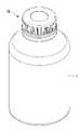
도 1은 본 발명의 일 실시예에 따른 분리수용 가능한 마개가 용기 본체에 결합된 상태를 도시한 사시도이다.
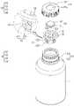
도 2는 도 1의 분해 사시도로서, 마개가 개방되었을 때의 분해 사시도이다.
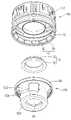
도 3는 본 발명의 일 실시예에 따른 분리수용 가능한 마개의 저면 분해 사시도이다.
도 4는 본 발명의 일 실시예에 따른 분리수용 가능한 마개가 용기 본체에 결합된 것을 나타낸 일 방향에서의 단면도이다.
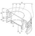
도 5는 본 발명의 일 실시예에 따른 분리수용 가능한 마개에서, 안착부에 밀폐부가 결합된 상태를 도시한 사시도이다.
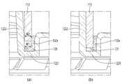
도 6는 본 발명의 일 실시예에 따른 분리수용 가능한 마개에서, 수용벽이 안착부와 밀폐부 사이의 공간에 삽입되는 상태를 도시한 도면으로서, (a)는 수용벽이 일부가 공간에 일부 삽입된 상태를 도시한 도면이고, (b)는 수용벽이 공간에 완전히 삽입된 상태를 도시한 도면이다.
도 7은 본 발명의 일 실시예에 따른 분리수용 가능한 마개를 일방향으로 절단했을 때의 단면 사시도이다.
도 8은 본 발명의 다른 실시예에 따른 분리수용 가능한 마개를 일방향으로 절단했을 때의 단면 사시도이다.
도 9는 본 발명의 또 다른 실시예에 따른 분리수용 가능한 마개에 구비된 밀폐부의 사시도이다.
도 10은 도 9의 밀폐부가 사용된 분리수용 가능한 마개에서, 수용벽이 안착부와 밀폐부 사이의 공간에 삽입되는 상태를 도시한 도면으로서, (a)는 수용벽이 일부가 공간에 일부 삽입된 상태를 도시한 도면이고, (b)는 수용벽이 공간에 완전히 삽입된 상태를 도시한 도면이다.1 is a perspective view showing a state in which a detachable stopper according to an embodiment of the present invention is coupled to a container body.
FIG. 2 is an exploded perspective view of FIG. 1 when the stopper is opened.
Figure 3 is an exploded perspective view of the bottom of the separably accommodable stopper according to an embodiment of the present invention.
Figure 4 is a cross-sectional view in one direction showing that the separably accommodable stopper is coupled to the container body according to one embodiment of the present invention.
5 is a perspective view showing a state in which a sealing part is coupled to a seating part in a closure capable of being separated and accommodated according to an embodiment of the present invention.
Figure 6 is a view showing a state in which the receiving wall is inserted into the space between the seating portion and the sealing portion in the separably accommodating stopper according to an embodiment of the present invention, (a) is a portion of the receiving wall is part of the space It is a drawing showing an inserted state, and (b) is a drawing showing a state in which the receiving wall is completely inserted into the space.
7 is a cross-sectional perspective view when a separably accommodable stopper according to an embodiment of the present invention is cut in one direction.
8 is a cross-sectional perspective view when a separably accommodable stopper according to another embodiment of the present invention is cut in one direction.
9 is a perspective view of a sealing part provided in a stopper capable of being separable according to another embodiment of the present invention.
10 is a view showing a state in which the receiving wall is inserted into the space between the seating part and the sealing part in the separably accommodating stopper using the sealing part of FIG. 9, (a) is a part of the receiving wall is partially inserted into the space It is a drawing showing a state, and (b) is a drawing showing a state in which the receiving wall is completely inserted into the space.
이하, 첨부된 도면을 참조하여 본 발명의 실시예들을 상세히 설명한다. 본 발명을 설명하는데 있어서, 해당 분야에 이미 공지된 기술 또는 구성에 대한 구체적인 설명을 부가하는 것이 본 발명의 요지를 불분명하게 할 수 있다고 판단되는 경우에는 상세한 설명에서 이를 일부 생략하도록 한다. 또한, 본 명세서에서 사용되는 용어들은 본 발명의 실시예들을 적절히 표현하기 위해 사용된 용어들로서, 이는 해당 분야의 관련된 사람 또는 관례 등에 따라 달라질 수 있다. 따라서, 본 용어들에 대한 정의는 본 명세서 전반에 걸친 내용을 토대로 내려져야 할 것이다.Hereinafter, embodiments of the present invention will be described in detail with reference to the accompanying drawings. In describing the present invention, if it is determined that adding a detailed description of a technology or configuration already known in the related field may obscure the gist of the present invention, some of them will be omitted from the detailed description. In addition, the terms used in this specification are terms used to properly express the embodiments of the present invention, which may vary depending on people or customs related to the field. Therefore, definitions of these terms will have to be made based on the content throughout this specification.
여기서 사용되는 전문용어는 단지 특정 실시예를 언급하기 위한 것이며, 본 발명을 한정하는 것을 의도하지 않는다. 여기서 사용되는 단수 형태들은 문구들이 이와 명백히 반대의 의미를 나타내지 않는 한 복수 형태들도 포함한다. 명세서에서 사용되는 '포함하는'의 의미는 특정 특성, 영역, 정수, 단계, 동작, 요소 및/또는 성분을 구체화하며, 다른 특정 특성, 영역, 정수, 단계, 동작, 요소, 성분 및/또는 군의 존재나 부가를 제외시키는 것은 아니다.The terminology used herein is intended only to refer to specific embodiments and is not intended to limit the present invention. As used herein, the singular forms also include the plural forms unless the phrases clearly indicate the opposite. As used herein, the meaning of 'comprising' specifies specific characteristics, regions, integers, steps, operations, elements and/or components, and other specific characteristics, regions, integers, steps, operations, elements, components and/or groups. does not exclude the presence or addition of
이하, 첨부된 도면을 참조하여 본 발명의 일 실시예에 따른 분리수용 가능한 마개(100)에 대해서 설명하도록 한다.Hereinafter, a
먼저, 도 1 내지 도 4를 참고하면, 본 발명의 일 실시예에 따른 분리수용 가능한 마개(100)는 캡부(110), 캡부(110)와 결합되는 안착부(120), 안착부(120)와 결합되는 밀폐부(130), 및 캡부(110)와 결합되는 임시고정부(140)를 포함한다.First, referring to FIGS. 1 to 4, the separable and
도 1에 도시한 것처럼, 캡부(110)는 용기 본체(1)와 결합하는 것으로서, 캡부(110)의 적어도 일부가 용기 본체(1)의 토출구(2) 내부로 삽입된다. 따라서, 본 예의 용기는 용기 본체(1) 및 용기 본체(1)에 결합된 마개(100)를 구비할 수 있다,As shown in FIG. 1 , the
이러한 캡부(110)는 상부 캡부(111), 외캡부(112), 수용벽(113) 및 결합벽(114)을 구비할 수 있다.The
상부 캡부(111)는 원형의 평면 형상을 갖고 판 형태로 이루어져 있고, 정해진 두께를 가질 수 있다. 또한, 상부 캡부(111)의 중앙에는 원형으로 함몰된 상부캡부홈(111a)이 위치한다. 이러한 상부캡부홈(111a)은 수용벽(113)과 대면하고 있는 부분일 수 있다.The
외캡부(112)는 상부 캡부(111)과 끊김없이 연결되어 있고, 상부 캡부(111)의 가장자리로부터 아래쪽 방향으로 연장되어 용기 본체(1)의 외주면에 결합된다. 구체적으로 외캡부(112)는 상부 캡부(111)의 단부로부터 상부 캡부(111)와 수직하도록 연장된다.The
또한, 외캡부(112)는 적어도 1회 절곡된 단차 구조를 가질 수 있다.In addition, the
외캡부(112)은 이미 기술한 것처럼, 상부 캡부(111)의 가장자리로부터 끊김없이 연결되어 있으므로, 외갭부(112)의 상부는 상부 캡부(111)와 동일한 지름을 가질 수 있다. 반면, 외캡부(112)의 하부는 단차 구조에 의해 상부 캡부(111)보다 큰 지름을 가질 수 있다.As already described, since the
하지만, 외갭부(112)의 단차 구조는 생략될 수 있고, 이 경우, 외갭부(112)의 상부와 하부의 지름은 서로 동일할 수 있다.However, the stepped structure of the outer-
이로 인해, 상부 캡부(111)과 외캡부(112)의 구조에 의해, 상부 캡부(111)는 마개(100)의 상부면을 이루고, 외캡부(112)는 마개(100)의 측면을 이룰 수 있다.For this reason, by the structure of the
수용벽(113)은 상부 캡부(111)로부터 아래쪽 방향으로 지면과 수직하게 연장될 수 있다. 구체적으로 수용벽(113)은 상부캡부홈(111a)의 내부 가장자리로부터 외캡부(112)와 평행하도록 연장될 수 있다. 이로 인해, 수용벽(113)은 상부캡부홈(111a)과 동일한 지름을 가질 수 있다.The receiving
결합벽(114)은, 도 4에 도시한 것처럼, 수용벽(113)과 평행하도록 상부 캡부(111)로부터 아래쪽 방향으로 연장될 수 있다. 또한, 결합벽(114)은 수용벽(113)과 소정거리 이격되도록 수용벽(113)의 외측, 즉 외캡부(112) 쪽으로 인접하게 위치할 수 있다.As shown in FIG. 4 , the
이러한 결합벽(114)은 도 4에 도시한 것처럼, 안착부(120)의 내측면의 적어도 일부와 밀착된다. 따라서, 결합벽(114)은 안착부(120)가 캡부(110)와 결합될 때 안착부(120)의 상부와 밀착되게 위치하므로, 안착부(120)의 결합 상태는 안전하게 유지되어 결합 구조에 대한 안정성이 향상된다.As shown in FIG. 4 , the
안착부(120)는 도 4에 도시한 것처럼 캡부(110)와 결합될 때 수용벽(113)의 적어도 일부를 수용하여 캡부(110)와의 밀착 결합이 이루어질 수 있도록 한다.As shown in FIG. 4 , the
따라서, 캡부(110)와의 결합을 위해, 안착부(120)의 평면 형상은 캡부(110)의 평면 형상과 동일할 수 있고, 한 예로, 원형의 평면 형상을 가질 수 있다.Therefore, for coupling with the
본 예에서, 안착부(120)의 하부는 막혀있고 상부는 개방되어 있으며, 측부의 일부도 개방되어 있다.In this example, the lower portion of the
이러한 안착부(120)는 안착부재(121), 안착부재(121)와 결합되어 위쪽 방향으로 연장되어 있는 연장부재(122), 연장부재(122)의 상단부에 결합되어 연장부재(122)의 상단부에 위치하는 테두리부재(123) 및 후크부(124)를 포함한다.The
안착부재(121)는 연장부재(122)와 끊김없이 연결되어 위쪽 방향으로 돌출되어 있는 평탄면이다.The seating
이러한 안착부재(121)는 연장부재(122)로 에워싸여져 가운데 부분에 내용물 보관 공간인 중공(122a)을 구비할 수 있다.The seating
이미 기술한 것처럼, 안착부(120)의 상부는 개방되어 있으므로, 안착부재(121)의 중공(122a)은 상부가 개방되어 있어, 캡슐 형태의 영양재와 같은 고체 내용물(미도시)이 개방된 상부를 통해 안착부재(121)의 중공(122a)에 위치하여 보관될 수 있다.As already described, since the top of the
이러한 안착부재(121)는 물리적인 힘에 의해 캡부(110)와의 결합 상태가 해제되어 캡부(110)와 분리되며, 캡부(110)의 접한 상태에서도 물리적인 힘에 이 해 좌회전이나 우회전 동작이 이루어질 수 있다.The seating
안착부재(121)의 돌출 높이에 대응하는 측면은 단차 구조를 갖고 있어 안착부재(121)의 지름은 서로 다른 적어도 두 개의 크기를 가질 수 있다.Since the side surface corresponding to the protrusion height of the
연장부재(122)는 결합되어 있는 안착부재(121)의 단부 즉, 측면의 단부에 정해진 거리만큼 이격되게 위치하고 있다.The
이러한 연장부재(122)는 안착부재(121)의 측면 단부와 끊김없이 연결되어 있고, 외측방향으로 연장되어 있는 평탄 부분(1221)과 이 평탄 부분(1221)과 연결되어 있고 평탄 부분(1221)의 연장방향과는 다른 방향(예, 상하 방향)으로 연장되어 있는 복수 개의 기둥 부분(1222)을 구비할 수 있다.The
평탄 부분(1221)은 지면과 수평하게 연장되어 있는 평탄면이다.The
따라서, 안착부(120)의 바닥면은 안착부재(121)와 평탄 부분(1221)을 구비할 수 있다. 안착부재(121)는 평탄 부분(1221)에서부터 위쪽 방향으로 정해진 높이만큼 돌출되어 있으므로, 평탄 부분(1221)은 안착부재(121)보다 낮은 높이를 가질 수 있다.Accordingly, the bottom surface of the
복수 개의 기둥 부분(1222)은 평탄 부분(1221)에 끊김없이 연결되어 위쪽 방향으로 연장되어 있다.The plurality of
이때, 각 기둥 부분(1222)은 해당 방향을 따라 지면에 대해 직각으로 연장되는 대신, 지면에 대해 90도보다 작은 각도로 위쪽 방향으로 연장될 수 있다. 이러한 각 기둥 부분(1222)은 직선으로 연장되거나 곡선으로 연장되거나 또는 도 4에 도시한 것처럼 직선 구간과 곡선 구간을 모두 구비할 수 있다.At this time, each
도 4에 도시한 것처럼, 각 기둥 부분(1222)이 직선 구간(P12a)과 곡선 구간(P12b)을 모두 구비하는 경우, 안착부재(121)와 인접한 하단부는 직선 구간(P21a)일 수 있고, 안착부재(121)보다 높은 위치에 위치하고 테두리부재(123)와 인접한 상단부는 곡선 구간(P21b)일 수 있다.As shown in Figure 4, when each
도 4에서, 직선 구간(P21a)은 외캡부(112)와 인접한 외측 방향으로 경사져 있을 수 있어, 캡부(110)와 안착부(120)가 결합될 때, 캡부(110)의 수용벽(113)과 기둥 부분(122)의 사이의 이격 거리(D1)는 위쪽 방향으로 갈수록 커질 수 있다.4, the straight section P21a may be inclined in an outward direction adjacent to the
곡선 구간(P21b)의 내부면[즉, 수용벽(113)과 인접한 면]은 직선 구간(P21a)의 내부면보다 좀더 외측에 위치하여, 수용벽(113)과의 이격 거리(D1)는 아래쪽보다 위쪽이 클 수 있고, 또한 직선 구간(P21a)에서의 이격 거리보다 클 수 있다. 이러한 이격 거리(D1)의 변화로 인해, 안착부(120)의 테두리부재(123)는 캡부(110)의 결합벽(114)과 외캡부(112) 사이에 안정적으로 위치하게 된다.The inner surface of the curved section P21b (that is, the surface adjacent to the receiving wall 113) is located more outside than the inner surface of the straight section P21a, so that the distance D1 from the receiving
이러한 곡선 구간(P21b)은 직선 구간(P21a)과의 연결 부분에서 곡면을 갖고 있고 나머지 부분에서는 외측으로 경사지거나 지면에 수직한 직선면을 가질 수 있다.The curved section P21b may have a curved surface at a portion connected to the straight section P21a and may have a straight surface inclined outward or perpendicular to the ground at the remaining portion.
복수 개의 기둥 부분(1222)은 정해진 간격으로 이격되게 평탄 부분(1221)의 가장자리에 연결되어 해당 방향인 위쪽 방향으로 연장될 수 있다.The plurality of
이처럼, 복수 개의 기둥 부분(1222)이 원형의 평면 형상을 갖는 평탄 부분(1221)의 단부인 가장자리에 정해진 간격으로 평탄 부분(1221)의 가장자리를 따라 이격되게 위치하므로, 인접한 두 기둥 부분(1222) 사이에는 빈 공간인 관통부(122b)가 위치한다.As such, since the plurality of
인접한 두 기둥 부분(1222) 사이에 위치하는 각 관통부(122b)는 도 2 및 도 3에 도시한 것처럼, 연장부재(122)의 측부를 관통하게 형성된다. 이러한 각 관통부(122b)는 평탄 부분(1221)와 테두리부재(123) 사이에 위치한다. 상하방향으로 길게 위치할 수 있다.As shown in FIGS. 2 and 3 , each through
관통부(122b)로 인해, 캡부(110)가 용기 본체(1)와 분리된 상태에서 용기 본체(1) 내부의 내용물인 유체 내용물(예를 들어, 유산균 발효음료 등)은 안착부(120)의 내부로 유입될 수 있다. 즉, 개방된 관통부(122b)를 통해 용기 본체(1)의 유체 내용물이 안착부(120)의 중공(122a) 속으로 유입될 수 있다Due to the penetrating
위에 기재한 것처럼, 기둥 부분(1222)은 안착부재(121)와 연결된 평탄 부분(1221)의 가장자리에 결합되어 있으므로, 기둥 부분(1222)은 평탄 부분(1221)의 연장 길이만큼의 안착부재(121)로부터 이격되어 있다.As described above, since the
따라서, 기둥 부분(1222)과 안착부재(121) 사이에는 평탄 부분(1221)으로 하부가 막혀있는 링(ring) 형상의 빈 공간(122c)이 존재한다.Therefore, a ring-shaped
따라서, 캡부(110)와 안착부(120)가 결합될 경우, 수용벽(113)의 적어도 일부는 안착부재(121) 및 연장부재(122) 사이에 위치한 빈 공간(122c) 속으로 삽입되어 밀착 결합될 수 있다. Therefore, when the
도 2 및 도 3을 참고하면, 테두리부재(123)는 연장부재(122)의 복수 개의 기둥 부분(1222)으로부터 외측방향으로 지면과 평행하게 연장된다. 본 예에서, 테두리부재(123)는 인접한 두 기둥 부분(1222) 사이에도 끊김없이 위치하므로, 테두리부재(123)의 평면 형상은 링 형상을 가질 수 있다.Referring to FIGS. 2 and 3 , the
이러한 테두리부재(123)는 안착부(120)가 용기 본체(1)의 토출구(2)에 삽입되는 경우, 이미 기술한 것처럼, 토출구(2)와 인접한 용기 본체(1)의 상단부 즉, 결합벽(114)과 외캡부(112) 사이의 상단부 내부면과 밀착될 수 있다.다. When the mounting
이러한 밀착 동작에 의해, 안착부(120)는 용기 본체(1)와 캡부(110) 사이에서 안정적으로 결합 상태가 유지될 수 있다.Due to this close contact operation, the
후크부(124)는 테두리부재(123)로부터 아래쪽 방향으로 연장된다. 후크부(124)는 용기 본체(1)의 상부 외측면에 밀착하여 결합된다.The
즉. 도 3 및 도 4에 도시한 것처럼, 후크부(124)의 단부는 외측 방향의 반대인 내측 방향[즉, 안착부(120) 쪽]으로 돌출되어 있어 용기 본체(1)의 상부 외측면에 함몰된 부분에 결합된다. 이와 같은 후크부(124)를 통해 안착부(120)는 용기 본체(1)에 견고하게 결합될 수 있다.In other words. As shown in FIGS. 3 and 4, the end of the
밀폐부(130)는 도 2 및 도 3에 도시한 것처럼 원형의 평면 형상을 갖고 있고, 도 5에 도시한 것처럼 안착부(120) 위에 위치하여 안착부(120)와 접하게 위치할 수 있다.As shown in FIGS. 2 and 3 , the sealing
따라서, 밀폐부(130)는 하부에 위치하는 안착부(120) 즉 안착부재(121) 및 연장부재(122)의 평탄 부분(1221)과 동일한 평면 윤곽을 가질 수 있다.Accordingly, the sealing
이에 따라, 밀폐부(130)는 가장자리 부분에 위치한 평탄 부분(131)과 이 평탄 부분(131)에 둘러싸여 있고 위쪽 방향으로 돌출되어 형성된 돌출 부분(132)을 구비할 수 있다.Accordingly, the sealing
평탄 부분(131)은 하부에 위치하는 안착부(120) 연장부재(122)의 평탄 부분(1221)과 접하게 위치하는 부분으로서 역시 지면에 평행하게 연장되어 있는 평탄면이다. 따라서, 평탄 부분(131)은 연장부재(122)의 평탄 부분(1221)과 동일하게 원형의 링 형상을 가질 수 있다.The
돌출 부분(132)은 평탄 부분(131)과 끊김없이 연결되어 있고, 하부에 위치하는 안착부(120)의 안착부재(121)와 접하게 위치하는 부분이다. 따라서, 돌출 부분(132)의 측면 역시 안착부재(121)의 측면과 동일하게 단차 구조를 가질 수 있다.The protruding
본 예에서, 돌출 부분(132)은 안착 부재(121)의 상부 평탄면에 접하게 위치하고 평탄 부분(131)과 평행한 평탄면부 및 평탄면부와 평탄 부분(131) 사이에서 서로 연결되게 위치하고 평탄 부분(131)이나 평탄면부와 교차하는(예, 직교하는) 수직면부를 구비할 수 있다.In this example, the protruding
수직면부는 안착부(120)의 측면과 접하게 위치할 수 있고, 밀폐부(130)의 측면을 이룰 수 있다.The vertical surface portion may be located in contact with the side surface of the
따라서, 본 예의 밀폐부(130a)의 돌출 부분은 상부가 평탄면부로 덮여 있어, 밀폐부(130)는 원형의 테두리를 갖고 있고 가운데 부분이 상부가 평탄면부로 막혀있는 테두리 모자 형상을 가질 수 있다.Therefore, the upper portion of the protruding portion of the sealing
본 예에서, 돌출 부분(132)은 인접한 기둥 부분(1222)와 완전히 접해 있지 않아, 돌출 부분(131)와 인접한 기둥 부분(1222) 사이에는 빈 틈인 빈 공간(122c)이 존재하게 된다. 따라서, 도 4에 도시한 것처럼, 이 빈 공간(122c) 속으로 캡(110)의 수용벽(113)의 일부가 삽입되어 위치하게 된다.In this example, the protruding
이때, 도 6에 도시한 것처럼, 서로 인접한 돌출 부분(131)와 기둥 부분(1222) 사이의 공간(122c)의 폭, 즉 간격(W1)은 그 속으로 삽입되는 수용벽(113)의 두께(W2)와 동일하거나 두께(W2)보다 작은 크기를 가질 수 있다.At this time, as shown in FIG. 6, the width of the
하지만, 본 예의 밀폐부(130)는 탄성을 갖는 재료(예, 실리콘(silicon)이나 천연 고무 등)를 함유하여, 밀폐부(130)는 탄성을 갖고 있다.However, the sealing
따라서, 캡부(110)와 안착부(120)가 결합될 때, 캡부(110)의 수용벽(113)은 도 6의 (a)에 도시한 것처럼, 평탄 부분(131)과 인접한 기둥 부분(1222) 사이의 빈 공간 속으로 삽입될 때 이 공간에 위치하고 있는 밀폐부(130)의 돌출 부분(132)를 내측으로 압축해 밀면서 안착부(120)의 하단 쪽으로, 즉, 밀폐부(130)의 평탄 부분(131)과 접할 때까지 삽입될 수 있다. 이때, 돌출 부재(132)의 측면에 위치한 단차 구조로 인해, 수용벽(113)의 하강 동작은 좀 더 원활히 이루어질 수 있다.Therefore, when the
캡부(110)의 수용벽(113)이 정해진 위치까지 하강하여 안착부(120)와의 결합이 완료되면 도 6의 (b) 및 도 7에 도시한 것처럼, 밀폐부(130)의 돌출 부분(132)은 탄성에 의한 위치가 복원되어 기둥 부분(1222) 쪽으로 압력을 가하게 된다.When the
따라서, 기둥 부분(1222)과 밀폐부(130)의 돌출 부분(132) 사이에 위치하는 캡부(110)의 수용벽(113)은 자신과 인접해 있는 기둥 부분(1222) 및 돌출 부분(132)과의 밀착력이 증가된다.Therefore, the receiving
이에 따라, 관통부(122b)를 막고 있는 수용벽(113)쪽으로 밀폐부(130)의 돌출 부분(132)에 의한 압력이 인가되어, 관통부(122b)에 대한 수용벽(113)의 밀폐력은 크게 향상된다. 따라서, 캡부(110)가 용기 본체(1)에 결합되어 있는 상태에서는 관통부(122b)를 통해 용기 본체(1)의 유체 내용물이 안착부(120)의 내부 공간(122a) 속으로 유입되지 않다.Accordingly, the pressure by the protruding
따라서, 안착부(120)의 공간(122a) 속에 위치하고 있는 고체 내용물과 용기 본체(1) 속에 담겨있는 유체 내용물은 서로 혼합되지 않고 안전하게 보관되어, 각 내용물의 보관 기간이 증가하고, 이로 인해, 해당 제품의 유통 기간 또한 증가한다.Therefore, the solid content located in the
이에 더해 또한, 안착부(120)의 연장부재(122)의 평탄 부분(1221)에도 밀폐부(130)의 평탄 부분(131)이 밀착되어 있으므로, 연장부재(122)의 하단부 쪽으로 용기 본체(1)에 담겨있는 유체 내용물의 유입 역시 차단된다.In addition, since the
임시고정부(140)는 용기 본체(1)를 둘러싸고 있고, 캡부(110) 및 용기 본체(1)의 적어도 일부에 결합된다.The
또한, 임시고정부(140)는 외력에 의해 캡부(110)가 회전함에 따라 적어도 일부가 용기 본체(1)로부터 이탈된다. 이러한 임시고정부(130)는 캡부(110)와 연결되어 있는 연결부(141) 및 연결부(141)에 연결되어 있고 용기 본체(1)의 외주면에 위치하는 언더컷부(142)를 포함할 수 있다.In addition, at least a part of the
이런 상태에서, 마개(100)의 개폐하기 위해 캡부(110)가 회전되면, 결합부(141)는 연결부(143)의 연결 상태가 끊어지면서 언더컷부(142)로부터 분리되어 이탈된다.In this state, when the
연결부(141)는 도 3에 도시한 것처럼 캡부(110)와 언더컷부(142) 사이에 위치하여, 캡부(110)와 언더컷부(142)를 서로 연결한다.As shown in FIG. 3 , the connecting
이러한 연결부(141)는 정해진 간격으로 캐부(110)의 하단 가장자리를 따라서 이격되게 위치하므로, 연결부(141)의 개수는 복수 개일 수 있다.Since these
이러한 연결부(143)를 상부 또는 하부에서 바라보면, 방사상으로 배치된다고 볼 수 있다.When looking at these connection parts 143 from the top or bottom, it can be seen that they are arranged radially.
이러한 연결부(143)는 캡부(110)의 회전 동작에 의해 그 연결 상태가 파손되어, 본 예의 마개(100)를 용기 본체(1)로부터 분리할 수 있다.The connection part 143 is broken by the rotational operation of the
즉, 사용자가 캡부(110)를 파지한 상태에서 외력을 가하여 회전시키면, 결합부(141)가 상방으로 분리되고 언더컷부(142)는 제자리인 용기 본체(1)의 외주면에 있게 된다.That is, when the user rotates the
결과적으로 연결부(141)는 연결되어 있는 캡부(110) 및 언더컷부(142)과 분리되어, 캡부(110) 역시 용기 본체(1)에 위치하는 언더컷부(142)과 분리된다.As a result, the
따라서, 사용자는 마개(100)를 열 수 있게 된다.Thus, the user can open the
언더컷부(142)는 내부가 비어 있는 형상으로 'V'자 형상을 가질 수 있다. 따라서, 이러한 언더컷부(142)는 용기 본체(1)의 외주면에 위치한 걸림턱(미도시)과 삽입 결합될 수 있다. 이때, 걸림턱은 언더컷(142)의 회전 동작 역시 방지한다.The undercut
이러한 삽입 결합에 의해 캡부(110)의 회전에 이루어질 때도, 언더컷부(142)는 용기 본체(1)의 해당 외주면에 회전되지 않고 위치하므로, 용이하게 연결부(141)가 파손되어 마개(100)의 개방이 이루어진다.Even when the
이러한 구조를 갖고 있는 마개(100)는 캡부(110)가 용기 본체(1)와 결합되어 용기 본체(1)의 토출구(2)를 막게 되면, 용기 본체(1)의 내부에는 내부공간(S1)이 형성된다.In the
또한, 캡부(110)와 안착부(120)가 결합된 마개(100)의 내부에는 상부 캡부(111), 수용벽(113) 및 안착부(120)가 이루는 밀폐공간(S2)이 형성된다. 구체적으로 상부 캡부(111), 수용벽(113) 및 안착부재(121)가 이루는 내부에 밀폐공간(S2)이 형성된다.In addition, inside the
이때, 캡부(110)의 내부로 안착부(120)가 결합된다. 구체적으로 수용벽(113)의 끝단은 안착부재(121)와 연결부재(122) 사이에 밀착되면서 삽입 고정된다. 또한, 결합벽(114)의 외측면은 연결부재(122)의 내측면과 밀착된다.At this time, the
위와 같이 캡부(110)와 안착부(120)가 결합된 상태에서 용기 본체(1)에 결합된다. 구체적으로 외캡부(112)의 내측 하부에는 결합부(131)가 결합되어 있다. 외캡부(112)의 내측면은 용기 본체(1)의 외측면과 밀착되도록 회전 결합된 상태이다. 또한, 테두리부재(123)는 토출구(2)와 인접한 용기 본체(1)의 끝단과 접하게 된다.As described above, the
이런 상태에서 사용자가 캡부(110)를 손으로 잡고 외력을 가하여 회전시키면, 캡부(110)와 결합부(141)가 용기(1), 안착부(120) 및 언더컷부(142)와 상하방향으로 분리된다. 이때, 언더컷부(142)는 결합부(141) 및 연결부(143)로부터 이탈된 후 용기 본체(1)의 외주면에 남아 있게 된다.In this state, when the user holds the
결합부(141)와 언더컷부(142)가 분리되는 과정에서, 연결부(143)는 결합부(141)에 연결된 상태로 언더컷부(142)와 분리될 수도 있다. 반대로 연결부(143)는 언더컷부(142)와 연결된 상태로 결합부(141)와 분리될 수도 있다.In the process of separating the
이러한 동작에 의해 마개(100)가 용기 본체(1)로부터 분리되어 사용자는 용기 본체(1)와 안착부(120)에 담겨있는 내용물을 섭취할 수 있다.By this operation, the
이러한 본 발명에 따르면, 개봉 전 캡부(110)가 안착부(120)와 결합되면, 캡부(110)의 수용벽(113)은 관통부(122b)가 위치하는 기둥 부분(1222)와 밀폐부(130) 사이에 위치하고 밀폐부(130)의 복원력에 의해 수용벽(113)쪽으로 압력이 인가된다. 이로 인해, 수용벽(113)과 기둥 부분(1222) 사이의 밀폐력이 증가한다.According to the present invention, when the
또한, 밀폐부(130)의 가장자리 부분(131)에 의해, 각 관통부(122b)의 하단에서의 밀폐력 역시 증가한다.In addition, the sealing force at the lower end of each penetrating
이에 따라, 수용벽(113)에 의한 용기 본체(1)의 내부공간(S1)의 밀폐력과 안착부(120)의 공간(122a)의 밀폐력이 증가하여 용기 본체(1)의 내부공간(S1)에 있는 유체 내용물과 안착부(120)의 공간(S2)에 있는 고체 내용물은 서로 섞이지 않게 된다.Accordingly, the sealing force of the inner space (S1) of the container body (1) by the receiving wall (113) and the sealing force of the space (122a) of the seating portion (120) increase, thereby increasing the inner space (S1) of the container body (1). The fluid content in the and the solid content in the space (S2) of the
또한, 개봉 후 캡부(110)가 용기 본체(1)와 안착부(120)로부터 분리되면, 관통부(122b)를 막고 있는 수용벽(113)이 해당 위치에서 이탈하여 관통부(122b)는 용기 본체(1)의 유체 내용물이 유입될 수 있는 개방 상태가 된다.In addition, when the
따라서, 이런 상태에서, 사용자가 용기 본체(1) 내의 유체 내용물을 음용하게 될 때 용기 본체(1) 내의 유체 내용물은 관통부(122b)를 통해 안착부(120)의 공간(122a) 속으로 유입되면서 편하게 안착부(120)에 위치하고 있는 고체 내용물도 편안하게 섭취하게 된다.Therefore, in this state, when the user drinks the fluid content in the
즉, 캡부(110)를 개봉하기 전까지는 용기 본체(1)와 마개(100)에 각각 담겨있는 유체 내용물과 고체 내용물이 서로 섞이지 않도록 하여 두 내용물의 변질 등의 문제를 방지하여, 유체 내용물과 고체 내용물 각각의 성분을 변질없이 신선하게 유지하여 보관할 수 있다.That is, until the
다음, 도 8을 참고로 하여, 본 발명의 다른 실시예에 따른 분리수용 가능한 마개(100a)를 설명한다.Next, with reference to FIG. 8, a
본 예의 분리 수용 가능한 마개(100a)는 도 1 내지 도 7에 도시한 분리수용 가능한 마개(100)와 비교할 때, 동일한 구조를 갖고 같은 동작을 수행하는 구성요소에 대해서는 같은 도면 부호를 부여하고 그에 대한 자세한 설명은 생략한다.When compared with the separably
본 예의 분리수용 가능한 마개(100a)는 밀폐부를 구비하고 있지 않으며, 안착부(120a)와 이 안착부(120a)에 삽입 장착되는 수용벽(113a)의 구조는 도 1 내지 도 7에 도시한 분리수용 가능한 마개(100)와 상이할 수 있다. 이러한 차이점을 제외하면, 본 예의 분리수용 가능한 마개(100a)는 도 1 내지 도 7에 도시한 분리수용 가능한 마개(100)와 동일할 구조를 가질 수 있다.The
도 8에 도시한 것처럼, 안착부(120a)는 안착부재(121) 및 평탄 부분(1221a)과 복수 개의 기둥 부분(1222)을 구비하는 연장부재(122a)를 구비할 수 있다.As shown in FIG. 8 , the
하지만, 본 예에서, 연장부분(122a)의 평탄 부분(1221a)은 캡부(110a)의 수용벽(113a)의 단부가 삽입되는 원형의 삽입홈을 구비할 수 있다. 따라서, 평탄 부분(1221a)은 위치에 따라 높이가 상이한 단차 구조를 갖고 있어, 주변보다 높이가 낮은 부분이 원형의 삽입홈을 형성할 수 있다.However, in this example, the
캡부(110a)의 수용벽(113a)의 단부는 삽입홈에 삽입되고, 삽입홈으로의 삽입을 위한 단면 형상을 갖고 있다. 따라서, 도 8에 도시한 것처럼, 수용벽(113a)의 단부의 단면 형상은 'ㄱ'자 형상을 가질 수 있어 수용벽(113a)은 상부 캡부(111)의 내부면에서부터 아래쪽 방향으로 직선으로 연장되어 있는 수용 부분과 이 수용 부분의 끝단에 돌출되어 삽입홈에 삽입되는 돌기부를 구비할 수 있다.An end of the receiving
이로 인해, 안착부재(121)와 인접한 수용벽(113a)의 내부면은 평탄면을 갖고 있는 반면, 연장부재(122a)와 인접한 수용벽(113a)의 외부면은 단차 구조를 가질 수 있다.Accordingly, the inner surface of the receiving
이러한 수용벽(113a)의 돌기부와 안착부(120a)의 삽입홈에 의해, 도 8에 도시한 것처럼, 수용벽(113a)의 삽입 동작이 이루어질 때, 돌기부는 안착부(120a)의 삽입홈에 삽입되어 해당 위치에 수용벽(113a)의 삽입 동작이 이루어질 수 있다.When the insertion operation of the receiving
이때, 돌기부의 폭은 삽입홈의 폭과 동일하거나 클 수 있고, 또한 수용 부분의 폭은 평탄 부분(1221a)의 폭과 동일하거나 작을 수 있다. 하지만 이때, 안착부(120a)는 플라스틱과 같이 탄성을 갖는 재료로 이루어지므로, 돌기부는 삽입홈에 안전하게 삽입 장착되어 수용벽(113a)은 기둥 부분(1222) 사이에 있는 관통부(122b)를 안전하게 밀폐하게 된다.In this case, the width of the protrusion may be equal to or greater than the width of the insertion groove, and the width of the accommodating portion may be equal to or smaller than that of the
또한, 도 1 내지 도 7에 도시한 마개(100)와 비교할 때, 별도의 밀폐부를 구비하지 않아도 되므로, 마개(100a)의 재료비가 감소하고 구조가 간단해지는 효과가 추가로 발생한다.In addition, compared to the
다음, 도 9 및 도 10을 참고하여, 본 발명의 또 다른 실시예에 따른 분리수용 가능한 마개를 설명한다.Next, referring to FIGS. 9 and 10, a detachable stopper according to another embodiment of the present invention will be described.
도 1 내지 도 7와 비교할 때, 본 예의 분리수용 가능한 마개는 밀폐부(130a)를 제외한 모든 구성요소는 도 1 내지 도 7과 동일하므로, 그에 대한 자세한 설명은 생략한다.When compared with FIGS. 1 to 7, since all components of the separable stopper of this example are the same as those of FIGS. 1 to 7 except for the sealing
안착부(120)와 결합되어 안착부(120) 위에 위치하는 밀폐부(130a)는, 밀폐부(130)와 달리, 안착부(120)의 안착부재(121)의 상부 평탄면과 접하게 위치하는 부분이 삭제될 수 있다.The sealing
따라서, 본 예의 밀폐부(130a)는, 도 9에 도시한 것처럼, 가장자리 부분에 위치한 평탄 부분(131)과 이 평탄 부분(131)에 둘러싸여 있고 위쪽 방향으로 돌출된 돌출 부분(132a)을 구비할 수 있다.Therefore, the sealing
이때, 돌출 부분(132a)은 안착부재(121)의 상부 평탄면과 접하는 부분인 평탄면부가 생략되고 단지 안착부재(121)의 측면과 접하게 위치하는 수직면부만을 구비할 수 있다. 따라서, 본 예의 돌출 부분(132a)은 상부가 개방될 수 있다. 이러한 돌출 부분(132a) 역시 밀폐부(130)와 같이 단차 구조를 가질 수 있다.At this time, the protruding
따라서, 밀폐부(130a)는 원형의 테두리를 갖고 있고 가운데 부분의 상부와 하부가 원형으로 개방되어 있는 테두리 모자 형상을 가질 수 있다.Accordingly, the sealing
하지만, 밀폐부(130a)의 구조에도 불구하고, 도 10의 (a)에 도시한 것처럼, 캡부(110)와 안착부(120)가 결합될 때, 캡부(110)의 수용벽(113)은 평탄 부분(131)과 인접한 기둥 부분(1222) 사이의 빈 공간 속으로 삽입될 때 이 공간에 위치하고 있는 밀폐부(130a)의 돌출 부분(132a)을 밀면서 평탄 부분(131)까지 안정적으로 삽입될 수 있다. 이때, 돌출 부재(132a)의 측면에 위치한 단차 구조로 인해, 수용벽(113)의 하강 동작은 좀 더 원활히 이루어질 수 있다.However, despite the structure of the sealing
캡부(110)의 수용벽(113)이 정해진 위치까지 하강하여 안착부(120)와의 결합이 완료되면 도 10의 (b)에 도시한 것처럼, 밀폐부(130a)의 돌출 부분(132a)은 탄성에 의한 위치가 복원되어 인접한 기둥 부분(1222) 쪽으로 압력을 가해, 수용벽(113)의 위치를 안정적으로 유지할 수 있도록 한다.When the
이러한 밀폐부(130a)를 구비할 경우, 밀폐부(130)의 제조 비용이 절감되며, 안착부(120)와 밀폐부(130a)의 결합이 좀 더 용이하게 행해질 수 있는 효과가 추가적으로 발휘될 수 있다.When the sealing
이상, 본 발명의 분리수용 가능한 마개의 실시예들에 대해 설명하였다. 본 발명은 상술한 실시예 및 첨부한 도면에 한정되는 것은 아니며, 본 발명이 속하는 분야에서 통상의 지식을 가진 자의 관점에서 다양한 수정 및 변형이 가능할 것이다. 따라서 본 발명의 범위는 본 명세서의 청구범위뿐만 아니라 이 청구범위와 균등한 것들에 의해 정해져야 한다.In the above, embodiments of the stopper capable of receiving separation of the present invention have been described. The present invention is not limited to the above-described embodiments and accompanying drawings, and various modifications and variations will be possible from the viewpoint of those skilled in the art to which the present invention belongs. Therefore, the scope of the present invention should be defined by not only the claims of this specification but also those equivalent to these claims.
1: 용기 본체2: 토출구
100, 100a: 분리수용 가능한 마개110, 110a: 캡부
111: 상부 캡부111a: 상부캡부홈
112: 외캡부113, 113a: 수용벽
114: 결합벽120, 120a: 안착부
121: 안착부재122, 122a: 연장부재
1221, 1221a: 평탄 부분1222: 기둥 부분
122a: 중공122b: 관통부
123: 테두리부재124: 후크부
130, 130a: 밀폐부131: 평탄 부분
132, 132a: 돌출 부분140: 임시고정부
141: 결합부142: 언더컷부
S1: 내부공간S2: 밀폐공간1: container body 2: discharge port
100, 100a:
111:
112:
114:
121: seating
1221, 1221a: Flat part 1222: Pillar part
122a: hollow 122b: penetrating portion
123: frame member 124: hook part
130, 130a: sealed portion 131: flat portion
132, 132a: protruding part 140: temporary fixing part
141: coupling part 142: undercut part
S1: inner space S2: closed space
Claims (16)
Translated fromKorean상기 캡부와 결합되고, 안착부재 및 상기 안착부재와 결합되어 있고 복수 개의 관통부를 구비하는 연장부재를 포함하는 안착부; 및
상기 안착부와 밀착되게 결합하는 밀폐부
를 포함하고,
상기 수용벽은 상기 연장 부재와 상기 밀폐부 사이의 공간에 삽입되어 상기 관통부를 막고,
상기 밀폐부는 가장자리 부분에 위치한 평탄 부분과 상기 평탄 부분에 둘러싸여 있고 위쪽 방향으로 돌출되어 있는 돌출 부분을 구비하고 있고,
상기 안착부재와 상기 밀폐부의 돌출 부분의 측면은 각각 단차 구조를 갖는
분리수용 가능한 마개.a cap portion coupled to the container body and including an upper cap portion and a receiving wall extending downwardly from the upper cap portion;
a seating portion coupled to the cap portion, including a seating member and an extension member coupled to the seating member and having a plurality of penetrating portions; and
Sealing part closely coupled to the seating part
including,
The receiving wall is inserted into the space between the extension member and the sealing portion to block the penetration portion;
The sealing part has a flat portion located at an edge portion and a protruding portion surrounded by the flat portion and protruding upward,
Side surfaces of the seating member and the protruding portion of the sealing portion each have a stepped structure.
Separable water stopper.
상기 연장부재는 상기 안착부재와 연결되어 있고 상기 밀폐부의 평탄 부분과 접해 있는 평탄 부분과 상기 연장부재의 평탄 부분에 연결되어 위쪽 방향으로 연장되어 있는 복수 개의 기둥 부분을 포함하고,
상기 관통부는 인접한 두 기둥 부분 사이에 위치하는 분리수용 가능한 마개.According to claim 1,
The extension member includes a flat portion connected to the seating member and in contact with the flat portion of the sealing portion and a plurality of pillar portions connected to the flat portion of the extension member and extending upward,
The through portion is separated and accommodated stopper located between two adjacent pillar portions.
상기 밀폐부는,
상기 돌출 부분의 상단에서 연장되고, 상기 안착부재의 상부 평탄면에 접하게 위치하는 평탄면부를 더 포함하는 분리수용 가능한 마개.According to claim 1,
The sealing part,
and a flat surface portion extending from an upper end of the protruding portion and positioned in contact with an upper flat surface of the seating member.
상기 수용벽은 상기 연장부재의 기둥 부분과 상기 밀폐부의 돌출 부분 사이에 위치하는 분리수용 가능한 마개.According to claim 1,
Wherein the receiving wall is located between the pillar portion of the extension member and the protruding portion of the sealing portion, and is capable of being detachedly accommodated.
서로 인접한 상기 연장부재의 기둥 부분과 상기 밀폐부의 돌출 부분 사이의 간격은 상기 수용벽의 두께보다 동일하거나 작은 분리수용 가능한 마개.According to claim 6,
A gap between the pillar portion of the extension member adjacent to each other and the protruding portion of the sealing portion is equal to or smaller than the thickness of the receiving wall.
상기 밀폐부는 탄성을 갖고 있는 분리수용 가능한 마개.According to claim 7,
The sealing portion is a stopper capable of receiving separation having elasticity.
상기 밀폐부는 실리콘이나 천연 고무로 이루어져 있는 분리수용 가능한 마개.According to claim 8,
The sealing part is made of silicone or natural rubber and can be separated.
상기 캡부는 상기 상부 캡부로부터 아래쪽 방향으로 연장되어 있고, 상기 수용벽의 외측에 위치하는 결합벽을 더 포함하고,
상기 결합벽은 상기 안착부의 내부면과 밀착되어 있는 분리수용 가능한 마개.According to claim 1,
The cap portion extends downward from the upper cap portion and further includes a coupling wall positioned outside the receiving wall,
The coupling wall is separably accommodating stopper in close contact with the inner surface of the seating portion.
상기 안착부는 상기 연장부재로부터 외측 방향으로 연장되어 있고, 상기 캡부의 상기 결합벽 외측에 위치하는 상부 캡부와 접해 있는 테두리부재를 더 포함하는 분리수용 가능한 마개.According to claim 14,
The seating portion extends outwardly from the extension member and further comprises a rim member in contact with an upper cap portion positioned outside the coupling wall of the cap portion.
상기 안착부는 상기 테두리부재로부터 아래쪽 방향으로 연장되어 있고 상기 용기 본체와 결합되는 후크부를 더 포함하는 분리수용 가능한 마개.According to claim 15,
The seating portion extends downward from the frame member and further includes a hook portion coupled to the container body.
Applications Claiming Priority (2)
| Application Number | Priority Date | Filing Date | Title |
|---|---|---|---|
| KR1020200116419 | 2020-09-10 | ||
| KR20200116419 | 2020-09-10 |
Publications (2)
| Publication Number | Publication Date |
|---|---|
| KR20220033958A KR20220033958A (en) | 2022-03-17 |
| KR102479972B1true KR102479972B1 (en) | 2022-12-21 |
Family
ID=80936235
Family Applications (1)
| Application Number | Title | Priority Date | Filing Date |
|---|---|---|---|
| KR1020210001070AActiveKR102479972B1 (en) | 2020-09-10 | 2021-01-05 | Separable and acceptable container cap |
Country Status (1)
| Country | Link |
|---|---|
| KR (1) | KR102479972B1 (en) |
Families Citing this family (1)
| Publication number | Priority date | Publication date | Assignee | Title |
|---|---|---|---|---|
| WO2024262877A1 (en)* | 2023-06-22 | 2024-12-26 | 최광민 | Cap and container having same |
Citations (4)
| Publication number | Priority date | Publication date | Assignee | Title |
|---|---|---|---|---|
| JP2007069952A (en)* | 2005-09-07 | 2007-03-22 | Masayuki Makita | Bottle cap |
| JP2008105738A (en)* | 2006-10-27 | 2008-05-08 | Irokuen World:Kk | Combined bottle cap |
| KR101643341B1 (en)* | 2015-02-27 | 2016-07-28 | 주식회사 야긴 | Capsule caps equipped with leak-proof hollow |
| WO2019170842A1 (en)* | 2018-03-08 | 2019-09-12 | Rpc Bramlage Gmbh | Closure device for a container |
Family Cites Families (3)
| Publication number | Priority date | Publication date | Assignee | Title |
|---|---|---|---|---|
| KR101344480B1 (en) | 2012-08-10 | 2013-12-23 | 이영재 | Bottle cap with granule additive in a container having inclined inner wall |
| KR20150075832A (en)* | 2013-12-26 | 2015-07-06 | 제이씨텍(주) | Bottle cap drinking with granule additive and beverage simultaneously |
| KR102140623B1 (en) | 2014-03-03 | 2020-08-03 | (주) 네추럴웨이 | Bottle cap with additive |
- 2021
- 2021-01-05KRKR1020210001070Apatent/KR102479972B1/enactiveActive
Patent Citations (4)
| Publication number | Priority date | Publication date | Assignee | Title |
|---|---|---|---|---|
| JP2007069952A (en)* | 2005-09-07 | 2007-03-22 | Masayuki Makita | Bottle cap |
| JP2008105738A (en)* | 2006-10-27 | 2008-05-08 | Irokuen World:Kk | Combined bottle cap |
| KR101643341B1 (en)* | 2015-02-27 | 2016-07-28 | 주식회사 야긴 | Capsule caps equipped with leak-proof hollow |
| WO2019170842A1 (en)* | 2018-03-08 | 2019-09-12 | Rpc Bramlage Gmbh | Closure device for a container |
Also Published As
| Publication number | Publication date |
|---|---|
| KR20220033958A (en) | 2022-03-17 |
Similar Documents
| Publication | Publication Date | Title |
|---|---|---|
| US20060108363A1 (en) | Source selecting cap and closure for multiple chamber bottles | |
| US5328058A (en) | Dropper bottle assembly with squeeze cap | |
| KR100571711B1 (en) | bottle cap assembly for simultaneously dissolve additives | |
| KR102616898B1 (en) | Container cap having double block membrane and container having the same | |
| EA024342B1 (en) | Bottle cap for dispersing supplement in situ | |
| US20170354289A1 (en) | Beverage System Including A Removable Piercer | |
| US20120223100A1 (en) | Bottle cap for dispersing powdered supplement in situ | |
| BRPI0712974B1 (en) | distribution system for one container | |
| CN103391886A (en) | Equipment for holding heterogeneous materials | |
| CN110710849A (en) | Baby straw cup | |
| KR20170037886A (en) | Universal bottle cap | |
| CN222474973U (en) | Container cover and beverage container comprising same | |
| KR102479972B1 (en) | Separable and acceptable container cap | |
| CN108349629A (en) | Container | |
| KR102353170B1 (en) | Bottle having containing member for preserving functional particles | |
| KR102305471B1 (en) | A separable and acceptable container cap | |
| KR100569199B1 (en) | Mixing vessel | |
| US20200079560A1 (en) | Beverage container | |
| KR100571747B1 (en) | bottle cap assembly for simultaneously dissolve additives | |
| WO2010004252A2 (en) | Closure element a fluid container | |
| KR102092360B1 (en) | Separable type container for liquid and solid | |
| KR20230094782A (en) | Container cap and container having the same | |
| KR200376968Y1 (en) | Airtight vessel | |
| WO2006055508A2 (en) | Source selecting cap and closure for multiple chamber bottles | |
| KR20220102983A (en) | Double cap capable of accommodating liquid and storage container including the same |
Legal Events
| Date | Code | Title | Description |
|---|---|---|---|
| PA0109 | Patent application | St.27 status event code:A-0-1-A10-A12-nap-PA0109 | |
| PA0201 | Request for examination | St.27 status event code:A-1-2-D10-D11-exm-PA0201 | |
| R18-X000 | Changes to party contact information recorded | St.27 status event code:A-3-3-R10-R18-oth-X000 | |
| PG1501 | Laying open of application | St.27 status event code:A-1-1-Q10-Q12-nap-PG1501 | |
| D13-X000 | Search requested | St.27 status event code:A-1-2-D10-D13-srh-X000 | |
| D14-X000 | Search report completed | St.27 status event code:A-1-2-D10-D14-srh-X000 | |
| E902 | Notification of reason for refusal | ||
| PE0902 | Notice of grounds for rejection | St.27 status event code:A-1-2-D10-D21-exm-PE0902 | |
| E13-X000 | Pre-grant limitation requested | St.27 status event code:A-2-3-E10-E13-lim-X000 | |
| P11-X000 | Amendment of application requested | St.27 status event code:A-2-2-P10-P11-nap-X000 | |
| P13-X000 | Application amended | St.27 status event code:A-2-2-P10-P13-nap-X000 | |
| E701 | Decision to grant or registration of patent right | ||
| PE0701 | Decision of registration | St.27 status event code:A-1-2-D10-D22-exm-PE0701 | |
| PR0701 | Registration of establishment | St.27 status event code:A-2-4-F10-F11-exm-PR0701 | |
| PR1002 | Payment of registration fee | St.27 status event code:A-2-2-U10-U11-oth-PR1002 Fee payment year number:1 | |
| PG1601 | Publication of registration | St.27 status event code:A-4-4-Q10-Q13-nap-PG1601 |