KR102479640B1 - Accessory and manufacturing method thereof - Google Patents
Accessory and manufacturing method thereofDownload PDFInfo
- Publication number
- KR102479640B1 KR102479640B1KR1020180021990AKR20180021990AKR102479640B1KR 102479640 B1KR102479640 B1KR 102479640B1KR 1020180021990 AKR1020180021990 AKR 1020180021990AKR 20180021990 AKR20180021990 AKR 20180021990AKR 102479640 B1KR102479640 B1KR 102479640B1
- Authority
- KR
- South Korea
- Prior art keywords
- cover member
- accessory
- base structure
- hemming
- facing
- Prior art date
- Legal status (The legal status is an assumption and is not a legal conclusion. Google has not performed a legal analysis and makes no representation as to the accuracy of the status listed.)
- Active
Links
Images


Classifications
- B—PERFORMING OPERATIONS; TRANSPORTING
- B26—HAND CUTTING TOOLS; CUTTING; SEVERING
- B26F—PERFORATING; PUNCHING; CUTTING-OUT; STAMPING-OUT; SEVERING BY MEANS OTHER THAN CUTTING
- B26F1/00—Perforating; Punching; Cutting-out; Stamping-out; Apparatus therefor
- B26F1/02—Perforating by punching, e.g. with relatively-reciprocating punch and bed
- A—HUMAN NECESSITIES
- A45—HAND OR TRAVELLING ARTICLES
- A45C—PURSES; LUGGAGE; HAND CARRIED BAGS
- A45C11/00—Receptacles for purposes not provided for in groups A45C1/00-A45C9/00
- A—HUMAN NECESSITIES
- A45—HAND OR TRAVELLING ARTICLES
- A45C—PURSES; LUGGAGE; HAND CARRIED BAGS
- A45C11/00—Receptacles for purposes not provided for in groups A45C1/00-A45C9/00
- A45C11/002—Receptacles for purposes not provided for in groups A45C1/00-A45C9/00 for storing portable handheld communication devices, e.g. pagers or smart phones
- A—HUMAN NECESSITIES
- A45—HAND OR TRAVELLING ARTICLES
- A45C—PURSES; LUGGAGE; HAND CARRIED BAGS
- A45C11/00—Receptacles for purposes not provided for in groups A45C1/00-A45C9/00
- A45C11/003—Receptacles for purposes not provided for in groups A45C1/00-A45C9/00 for storing portable computing devices, e.g. laptops, tablets or calculators
- A—HUMAN NECESSITIES
- A45—HAND OR TRAVELLING ARTICLES
- A45C—PURSES; LUGGAGE; HAND CARRIED BAGS
- A45C13/00—Details; Accessories
- A45C13/36—Reinforcements for edges, corners, or other parts
- B—PERFORMING OPERATIONS; TRANSPORTING
- B26—HAND CUTTING TOOLS; CUTTING; SEVERING
- B26F—PERFORATING; PUNCHING; CUTTING-OUT; STAMPING-OUT; SEVERING BY MEANS OTHER THAN CUTTING
- B26F1/00—Perforating; Punching; Cutting-out; Stamping-out; Apparatus therefor
- B26F1/38—Cutting-out; Stamping-out
- B26F1/40—Cutting-out; Stamping-out using a press, e.g. of the ram type
- B—PERFORMING OPERATIONS; TRANSPORTING
- B32—LAYERED PRODUCTS
- B32B—LAYERED PRODUCTS, i.e. PRODUCTS BUILT-UP OF STRATA OF FLAT OR NON-FLAT, e.g. CELLULAR OR HONEYCOMB, FORM
- B32B27/00—Layered products comprising a layer of synthetic resin
- B32B27/06—Layered products comprising a layer of synthetic resin as the main or only constituent of a layer, which is next to another layer of the same or of a different material
- B32B27/08—Layered products comprising a layer of synthetic resin as the main or only constituent of a layer, which is next to another layer of the same or of a different material of synthetic resin
- B—PERFORMING OPERATIONS; TRANSPORTING
- B32—LAYERED PRODUCTS
- B32B—LAYERED PRODUCTS, i.e. PRODUCTS BUILT-UP OF STRATA OF FLAT OR NON-FLAT, e.g. CELLULAR OR HONEYCOMB, FORM
- B32B27/00—Layered products comprising a layer of synthetic resin
- B32B27/12—Layered products comprising a layer of synthetic resin next to a fibrous or filamentary layer
- B—PERFORMING OPERATIONS; TRANSPORTING
- B32—LAYERED PRODUCTS
- B32B—LAYERED PRODUCTS, i.e. PRODUCTS BUILT-UP OF STRATA OF FLAT OR NON-FLAT, e.g. CELLULAR OR HONEYCOMB, FORM
- B32B27/00—Layered products comprising a layer of synthetic resin
- B32B27/36—Layered products comprising a layer of synthetic resin comprising polyesters
- B32B27/365—Layered products comprising a layer of synthetic resin comprising polyesters comprising polycarbonates
- B—PERFORMING OPERATIONS; TRANSPORTING
- B32—LAYERED PRODUCTS
- B32B—LAYERED PRODUCTS, i.e. PRODUCTS BUILT-UP OF STRATA OF FLAT OR NON-FLAT, e.g. CELLULAR OR HONEYCOMB, FORM
- B32B27/00—Layered products comprising a layer of synthetic resin
- B32B27/40—Layered products comprising a layer of synthetic resin comprising polyurethanes
- B—PERFORMING OPERATIONS; TRANSPORTING
- B32—LAYERED PRODUCTS
- B32B—LAYERED PRODUCTS, i.e. PRODUCTS BUILT-UP OF STRATA OF FLAT OR NON-FLAT, e.g. CELLULAR OR HONEYCOMB, FORM
- B32B3/00—Layered products comprising a layer with external or internal discontinuities or unevennesses, or a layer of non-planar shape; Layered products comprising a layer having particular features of form
- B32B3/02—Layered products comprising a layer with external or internal discontinuities or unevennesses, or a layer of non-planar shape; Layered products comprising a layer having particular features of form characterised by features of form at particular places, e.g. in edge regions
- B—PERFORMING OPERATIONS; TRANSPORTING
- B32—LAYERED PRODUCTS
- B32B—LAYERED PRODUCTS, i.e. PRODUCTS BUILT-UP OF STRATA OF FLAT OR NON-FLAT, e.g. CELLULAR OR HONEYCOMB, FORM
- B32B3/00—Layered products comprising a layer with external or internal discontinuities or unevennesses, or a layer of non-planar shape; Layered products comprising a layer having particular features of form
- B32B3/26—Layered products comprising a layer with external or internal discontinuities or unevennesses, or a layer of non-planar shape; Layered products comprising a layer having particular features of form characterised by a particular shape of the outline of the cross-section of a continuous layer; characterised by a layer with cavities or internal voids ; characterised by an apertured layer
- B32B3/266—Layered products comprising a layer with external or internal discontinuities or unevennesses, or a layer of non-planar shape; Layered products comprising a layer having particular features of form characterised by a particular shape of the outline of the cross-section of a continuous layer; characterised by a layer with cavities or internal voids ; characterised by an apertured layer characterised by an apertured layer, the apertures going through the whole thickness of the layer, e.g. expanded metal, perforated layer, slit layer regular cells B32B3/12
- B—PERFORMING OPERATIONS; TRANSPORTING
- B32—LAYERED PRODUCTS
- B32B—LAYERED PRODUCTS, i.e. PRODUCTS BUILT-UP OF STRATA OF FLAT OR NON-FLAT, e.g. CELLULAR OR HONEYCOMB, FORM
- B32B5/00—Layered products characterised by the non- homogeneity or physical structure, i.e. comprising a fibrous, filamentary, particulate or foam layer; Layered products characterised by having a layer differing constitutionally or physically in different parts
- B32B5/02—Layered products characterised by the non- homogeneity or physical structure, i.e. comprising a fibrous, filamentary, particulate or foam layer; Layered products characterised by having a layer differing constitutionally or physically in different parts characterised by structural features of a fibrous or filamentary layer
- B32B5/022—Non-woven fabric
- B—PERFORMING OPERATIONS; TRANSPORTING
- B32—LAYERED PRODUCTS
- B32B—LAYERED PRODUCTS, i.e. PRODUCTS BUILT-UP OF STRATA OF FLAT OR NON-FLAT, e.g. CELLULAR OR HONEYCOMB, FORM
- B32B5/00—Layered products characterised by the non- homogeneity or physical structure, i.e. comprising a fibrous, filamentary, particulate or foam layer; Layered products characterised by having a layer differing constitutionally or physically in different parts
- B32B5/02—Layered products characterised by the non- homogeneity or physical structure, i.e. comprising a fibrous, filamentary, particulate or foam layer; Layered products characterised by having a layer differing constitutionally or physically in different parts characterised by structural features of a fibrous or filamentary layer
- B32B5/024—Woven fabric
- B—PERFORMING OPERATIONS; TRANSPORTING
- B32—LAYERED PRODUCTS
- B32B—LAYERED PRODUCTS, i.e. PRODUCTS BUILT-UP OF STRATA OF FLAT OR NON-FLAT, e.g. CELLULAR OR HONEYCOMB, FORM
- B32B5/00—Layered products characterised by the non- homogeneity or physical structure, i.e. comprising a fibrous, filamentary, particulate or foam layer; Layered products characterised by having a layer differing constitutionally or physically in different parts
- B32B5/02—Layered products characterised by the non- homogeneity or physical structure, i.e. comprising a fibrous, filamentary, particulate or foam layer; Layered products characterised by having a layer differing constitutionally or physically in different parts characterised by structural features of a fibrous or filamentary layer
- B32B5/026—Knitted fabric
- H—ELECTRICITY
- H04—ELECTRIC COMMUNICATION TECHNIQUE
- H04B—TRANSMISSION
- H04B1/00—Details of transmission systems, not covered by a single one of groups H04B3/00 - H04B13/00; Details of transmission systems not characterised by the medium used for transmission
- H04B1/38—Transceivers, i.e. devices in which transmitter and receiver form a structural unit and in which at least one part is used for functions of transmitting and receiving
- H04B1/3827—Portable transceivers
- H04B1/3888—Arrangements for carrying or protecting transceivers
- A—HUMAN NECESSITIES
- A45—HAND OR TRAVELLING ARTICLES
- A45C—PURSES; LUGGAGE; HAND CARRIED BAGS
- A45C11/00—Receptacles for purposes not provided for in groups A45C1/00-A45C9/00
- A45C11/001—Receptacles for purposes not provided for in groups A45C1/00-A45C9/00 for storing portable audio devices, e.g. headphones or digital music players
- A45C2011/002—
- A45C2011/003—
- B—PERFORMING OPERATIONS; TRANSPORTING
- B32—LAYERED PRODUCTS
- B32B—LAYERED PRODUCTS, i.e. PRODUCTS BUILT-UP OF STRATA OF FLAT OR NON-FLAT, e.g. CELLULAR OR HONEYCOMB, FORM
- B32B2250/00—Layers arrangement
- B32B2250/03—3 layers
- B—PERFORMING OPERATIONS; TRANSPORTING
- B32—LAYERED PRODUCTS
- B32B—LAYERED PRODUCTS, i.e. PRODUCTS BUILT-UP OF STRATA OF FLAT OR NON-FLAT, e.g. CELLULAR OR HONEYCOMB, FORM
- B32B2553/00—Packaging equipment or accessories not otherwise provided for
- B—PERFORMING OPERATIONS; TRANSPORTING
- B32—LAYERED PRODUCTS
- B32B—LAYERED PRODUCTS, i.e. PRODUCTS BUILT-UP OF STRATA OF FLAT OR NON-FLAT, e.g. CELLULAR OR HONEYCOMB, FORM
- B32B2571/00—Protective equipment
Landscapes
- Engineering & Computer Science (AREA)
- Textile Engineering (AREA)
- Life Sciences & Earth Sciences (AREA)
- Forests & Forestry (AREA)
- Mechanical Engineering (AREA)
- Computer Networks & Wireless Communication (AREA)
- Signal Processing (AREA)
- Casings For Electric Apparatus (AREA)
- Telephone Set Structure (AREA)
Abstract
Translated fromKorean
Description
Translated fromKorean본 문서에 개시된 다양한 실시예들은 액세서리 및 이의 제조 방법에 관한 것이다.Various embodiments disclosed herein relate to accessories and methods of manufacturing the same.
전자 장치라 함은, 가전제품으로부터, 전자 수첩, 휴대용 멀티미디어 재생기, 이동통신 단말기, 태블릿 PC, 영상/음향 장치, 데스크톱 / 랩톱 컴퓨터, 차량용 내비게이션 등, 탑재된 프로그램에 따라 특정 기능을 수행하는 장치를 의미한다. 예를 들면, 이러한 전자 장치들은 저장된 정보를 음향이나 영상으로 출력할 수 있다. 전자 장치의 집적도가 높아지고, 초고속, 대용량 무선통신이 보편화되면서, 최근에는, 이동통신 단말기 하나에 다양한 기능이 탑재되고 있다.Electronic devices include devices that perform specific functions according to loaded programs, such as home appliances, electronic notebooks, portable multimedia players, mobile communication terminals, tablet PCs, video/audio devices, desktop/laptop computers, car navigation systems, etc. it means. For example, these electronic devices may output stored information as sound or image. As the degree of integration of electronic devices increases and ultra-high-speed, high-capacity wireless communication becomes common, recently, a single mobile communication terminal is equipped with various functions.
전자 장치에는 일면에 디스플레이가 배치되어, 장치 운용에 따른 화면을 출력할 수 있다. 상기 이동통신 단말기와 같은 전자 장치는 휴대 목적을 위해 얇고 가볍게 만들어지고 있다. 이러한 휴대용 전자 장치는 외부의 물리적인 충격에 따라 파손의 우려가 있기 때문에, 전자 장치의 외관을 감싸는 보호 커버 등이 액세서리 형태로 제공될 수 있다.A display is disposed on one surface of the electronic device, and a screen according to device operation can be output. Electronic devices such as the mobile communication terminal are being made thin and light for portability. Since such a portable electronic device may be damaged by external physical impact, a protective cover covering the exterior of the electronic device may be provided in the form of an accessory.
전자 장치의 외관을 감싸는 액세서리로서의 보호 커버는, 단순히 전자 장치를 보호하는 기능만 제공할 뿐만 아니라, 사용자로 하여금 미적 심미감을 불러일으키는 효과를 가질 수 있다.A protective cover as an accessory that surrounds the exterior of an electronic device not only provides a function of simply protecting the electronic device, but also has an effect of arousing an aesthetic sense to the user.
이를 위해 액세서리에는 하드 케이스, 폴리우레탄(polyurethane), 가죽, 직물, 부직포, 편물 소재 등 다양한 소재가 사용되어 제조될 수 있고, 어떤 실시예에 따르면 하나의 액세서리에 다양한 소재들이 결합될 수도 있다.To this end, the accessory may be manufactured using various materials such as a hard case, polyurethane, leather, fabric, nonwoven fabric, and knitted material, and according to some embodiments, various materials may be combined in one accessory.
예를 들면, 폴리카보네이트(polycarbonate, PC) 소재로 이루어진 하드 케이스에 직물과 편물을 조합하여 액세서리를 제조할 수 있다. 직물은 하나 또는 둘 이상의 종류를 포함하는실이 날실(경사)와 씨실(위사)로서 직각으로 교차하여 이루어진 원단이고, 편물은 한 가닥 또는 여러 가닥의 실로 루프(코, loop)를 만들어 인접한 루프들을 전후 좌우로 엮어 이루어진 원단이다. 편물은, 스웨터류, 코트, 모자 등의 소재로 사용되며, 질감이 좋아 극세사 이불 등의 소재로도 사용될 수 있다. 따라서, 편물은 좋은 질감으로 인해 액세서리의 표면 중 신체 접촉이 많은 부분을 감싸는 겉감으로서 적합할 수 있다.For example, an accessory may be manufactured by combining a fabric and a knitted fabric in a hard case made of a polycarbonate (PC) material. A fabric is a fabric made by crossing yarns containing one or more than two types at right angles as warp (warp) and weft (weft) yarns, and knitted fabric is made by making loops with one or more yarns and connecting adjacent loops. It is a fabric that is woven from the front and back to the left and right. Knitted fabric is used as a material for sweaters, coats, hats, etc., and can also be used as a material for microfiber blankets because of its good texture. Therefore, the knitted fabric may be suitable as an outer fabric covering a part of the surface of the accessory that is in contact with the body due to its good texture.
예를 들면, 하드케이스에 겉감으로서 편물을 사용하고 안감으로서 직물을 사용하여 제조된 액세서리에 있어서, 편물의 경우 컷팅 과정에서 보풀이 생길 수 있다. 이때 편물이 포함된 겉감과 직물이 포함된 안감의 경계가 서로 맞대어져 있으면 상기 편물에서 생긴 보풀이 경계 상에 그대로 노출될 수 있다. 액세서리로서 모바일 전자 장치의 보호 커버를 예시로 들면, 편물이 포함된 겉감과 직물이 포함된 안감의 경계가, 보호 커버 내측면의 평면 상에 형성될 수 있다. 이러한 경우, 편물에서 생긴 보풀이 전자 장치가 장착되는 공간을 통해 액세서리의 외관에 드러나게 되므로 제품의 미려함을 저하시키는 원인이 될 수 있다.For example, in an accessory manufactured by using a knitted fabric as an outer material and a fabric as a lining in a hard case, fluff may be generated during a cutting process in the case of the knitted fabric. At this time, if the boundary between the outer fabric containing the knitted fabric and the lining containing the fabric face each other, fluff generated from the knitted fabric may be exposed as it is on the boundary. Taking a protective cover for a mobile electronic device as an accessory, a boundary between an outer fabric including a knitted fabric and a lining including a fabric may be formed on a flat surface of an inner surface of the protective cover. In this case, fluff generated from the knitted fabric is exposed on the exterior of the accessory through a space in which the electronic device is mounted, and thus may cause deterioration in the beauty of the product.
한 실시예에 따르면, 하드케이스에 겉감으로서 편물을 사용하고 안감으로서 직물을 사용하여 액세서리를 제조하는 방법에 있어서, 겉감과 안감의 경계라인을 하드케이스의 평면이 아닌, 내측면에 형성시키면 시인성을 낮출 수 있게 되어 보풀이 외관으로 드러나지 않을 수 있다. 다만, 이와 같이 하드케이스의 내측면에 경계라인을 형성하는 것은, 평면에 경계라인을 형성하는 것에 비해 가공 공정의 난이도가 높아질 수 있다. 예컨대, 겉감과 안감의 경계라인을 하드케이스의 평면 상에 형성하는 경우에는 비교적 간단한 컷팅 공정을 이용(예: 수직 상방 또는 수직 하방으로의 직선적인 움직임을 갖는 공구 이용)할 수 있으나, 하드케이스의 내측면에 경계라인을 형성하는 경우에는 보다 많은 비용이 요구되는 공정(예: 플라잉 컷(또는 T컷))이 있을수 있다. 상기 플라잉 컷 공정은 피 성형제품의 내부 표면을 성형하기 위해 사용 가능한 공정으로서, 수직 상방 또는 수직 하방으로의 움직임뿐만 아니라, 수평 방향의 움직임을 갖는 공구를 이용할 수 있다. 플라잉 컷에 사용되는 기구는 높은 자유도로 움직일 수 있어 정밀한 절삭 작업이 요구되는 공정에 이용될 수 있으나, 수직적인 움직임만을 요하는 기구에 비해 상대적으로 복잡한 구성을 가지고, 이를 이용하여 액세서리를 제조하려면 보다 많은 비용이 요구될 수 있다.According to one embodiment, in the method of manufacturing an accessory using a knitted fabric as an outer fabric and a fabric as a lining in a hard case, when the boundary line between the outer fabric and the lining is formed on the inner surface of the hard case, not on the plane, visibility is improved. It can be lowered so that the fluff may not be visible. However, forming the boundary line on the inner surface of the hard case in this way may increase the difficulty of the processing process compared to forming the boundary line on the plane. For example, in the case of forming the boundary line between the outer fabric and the lining on the plane of the hard case, a relatively simple cutting process may be used (e.g., a tool having a linear movement vertically upward or vertically downward) may be used. In the case of forming a boundary line on the inner surface, there may be a process (eg, flying cut (or T-cut)) that requires more cost. The flying cut process is a process usable for shaping the inner surface of a product to be molded, and a tool having vertical upward or downward movement as well as horizontal movement may be used. The tools used for flying cut can be moved with a high degree of freedom, so they can be used in processes that require precise cutting work. High costs may be required.
또한, 비교적 정밀한 작업이 가능한 플라잉 컷 공정을 이용하더라도, 원단으로서 편물 재질을 이용하는 경우에는, 컷팅되는 부분에서 편물 원단이 말리는 현상이 발생할 수 있다.In addition, even if a flying cut process capable of relatively precise work is used, in the case of using a knitted fabric as a fabric, a phenomenon in which the knitted fabric is rolled may occur in the cut portion.
본 문서에 개시된 다양한 실시예들에서는, 보풀 발생으로 인해 제품의 미려함이 저하되는 것을 방지하는 액세서리 및 액세서리 제조 방법 등을 제공할 수 있다.In various embodiments disclosed in this document, it is possible to provide an accessory and a method for manufacturing the accessory that prevent deterioration in beauty of a product due to generation of fluff.
본 문서에 개시된 다양한 실시예들에 따르면, 제 1 방향으로 향하는 전면, 상기 제 1 방향의 반대인 제 2 방향으로 향하는 후면이 형성된 플레이트 및 상기 플레이트의 가장자리로부터 연장된 사이드 멤버를 포함하는 베이스 구조; 상기 후면을 포함한 상기 베이스 구조의 적어도 일부 표면을 커버하는 제 1 커버부재로서, 상기 후면을 마주보는 제 1 평면부, 상기 사이드 멤버의 외측면을 마주보는 제 1 엣지부 및 상기 사이드 멤버의 내측면의 적어도 일부분을 마주보는 제 1 헤밍부를 포함하는 제 1 커버부재; 및 상기 전면을 포함한 상기 베이스 구조의 적어도 일부 표면을 커버하는 제 2 커버부재로서, 상기 전면을 마주보는 제 2 평면부, 상기 사이드 멤버의 내측면의 적어도 일부분을 마주보는 제 2 엣지부를 포함하는 제 2 커버부재;를 포함하고, 상기 제 2 엣지부의 적어도 일부분이 상기 제 1 헤밍부의 적어도 일부분을 오버랩(overlap)하는 액세서리를 제공할 수 있다.According to various embodiments disclosed herein, a base structure including a plate having a front surface facing a first direction and a rear surface facing a second direction opposite to the first direction, and a side member extending from an edge of the plate; A first cover member covering at least a portion of the surface of the base structure including the rear surface, comprising: a first flat part facing the rear surface, a first edge part facing the outer surface of the side member, and an inner surface of the side member A first cover member including a first hemming portion facing at least a portion of the; and a second cover member covering at least a portion of the surface of the base structure including the front surface, including a second plane portion facing the front surface and a second edge portion facing at least a portion of an inner surface of the side member. 2 cover members; and an accessory in which at least a portion of the second edge portion overlaps at least a portion of the first hemming portion may be provided.
본 문서에 개시된 다양한 실시예들에 따르면, 플레이트 및 상기 플레이트의 가장자리로부터 연장된 사이드 멤버를 포함하는 베이스 구조, 편물(knit)로 형성된 제 1 커버부재, 및 상기 제 1 커버부재와 다른 재질의 소재를 포함하는제 2 커버부재를 준비하는 공정; 상기 베이스 구조의 플레이트, 상기 사이드 멤버의 외측면 및 사이드 멤버의 내측면의 적어도 일부분을 마주보도록, 상기 베이스 구조에 상기 제 1 커버부재를 커버하는 공정; 상기 제 1 커버부재의 적어도 일부가 상기 베이스 구조에 결합(coupling)되는 공정; 상기 제 1 커버부재의 적어도 일부를 컷팅하는 공정; 상기 베이스 구조에 상기 제 2 커버부재를 커버하는 공정; 및 상기 제 2 커버부재의 적어도 일부가 상기 제 1 커버부재의 적어도 일부에 오버랩(overlap)된 채로 결합(coupling)되는 공정;을 포함하는 액세서리의 제조 방법을 제공할 수 있다.According to various embodiments disclosed in this document, a base structure including a plate and a side member extending from an edge of the plate, a first cover member formed of a knitted fabric, and a material different from that of the first cover member Step of preparing a second cover member comprising a; covering the first cover member on the base structure so that at least a portion of the plate of the base structure, the outer surface of the side member and the inner surface of the side member face each other; coupling at least a portion of the first cover member to the base structure; cutting at least a portion of the first cover member; covering the second cover member on the base structure; and coupling at least a portion of the second cover member to at least a portion of the first cover member while being overlapped.
본 문서에 개시된 다양한 실시예들에 따르면, 제 1 방향으로 향하는 전면, 상기 제 1 방향의 반대인 제 2 방향으로 향하는 후면이 형성된 플레이트 및 상기 전면 상에 전자 장치가 안착되도록 형성된 공간을 둘러싸는 사이드 멤버를 포함하는 베이스 구조; 상기 후면을 포함한 상기 베이스 구조의 적어도 일부 표면을 커버하는 제 1 커버부재로서, 상기 후면을 마주보는 제 1 평면부, 상기 사이드 멤버의 외측면을 마주보는 제 1 엣지부 및 상기 사이드 멤버의 내측면의 적어도 일부분을 마주보는 제 1 헤밍부를 포함하며, 편물(knit)로 형성된 제 1 커버부재; 및 상기 전면을 포함한 상기 베이스의 적어도 일부 표면을 커버하는 제 2 커버부재로서, 상기 전면을 마주보는 제 2 평면부, 상기 사이드 멤버의 내측면의 적어도 일부분을 마주보고 상기 제 1 헤밍부의 적어도 일부를 오버랩(overlap) 하도록 형성된 제 2 엣지부를 포함하며, 상기 제 1 커버부재와 다른 재질인 제 2 커버부재;를 포함하고, 상기 사이드 멤버에는 상기 전자 장치의 입출력 장치가 형성되는 부분에 대응하기 위하여 개구부가 형성되고, 상기 제 1 커버부재와 일체로 형성되고, 상기 전면의 적어도 일부를 마주보고, 상기 제 2 개구부에 대응하는 위치에 형성되는 제 2 헤밍부로서, 상기 제 2 평면부의 일측의 단부와 맞닿는 단부를 가지는 제 2 헤밍부를 포함하는 전자 장치에 탈착 가능한 액세서리를 제공할 수 있다.According to various embodiments disclosed in this document, a plate having a front surface facing a first direction and a rear surface facing a second direction opposite to the first direction, and a side surface surrounding a space formed on the front surface to accommodate an electronic device a base structure comprising members; A first cover member covering at least a portion of the surface of the base structure including the rear surface, comprising: a first flat part facing the rear surface, a first edge part facing the outer surface of the side member, and an inner surface of the side member A first cover member including a first hemming portion facing at least a portion of the first cover member formed of a knitted fabric; and a second cover member covering at least a portion of the surface of the base including the front surface, wherein the second flat portion facing the front side faces at least a portion of the inner surface of the side member and at least a portion of the first hemming portion is formed. A second cover member including a second edge portion formed to overlap and made of a material different from that of the first cover member, wherein the side member has an opening to correspond to a portion where the input/output device of the electronic device is formed. A second hemming portion formed integrally with the first cover member, facing at least a portion of the front surface, and formed at a position corresponding to the second opening, the end of one side of the second flat portion and An accessory detachable to an electronic device including a second hemming portion having an abutting end may be provided.
본 문서에 개시된 다양한 실시예들에 따르면, 액세서리에서 생기는 보풀에 의해 외관의 미려함이 저하되는 것을 방지할 수 있다.According to various embodiments disclosed in this document, it is possible to prevent deterioration in appearance due to fluff generated from accessories.
다양한 실시예들에 따르면, 액세서리의 가공 비용 및 시간 등을 절감할 수 있다.According to various embodiments, it is possible to reduce the processing cost and time of accessories.
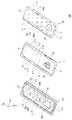
도 1은, 본 문서에 개시된 다양한 실시예들에 따른, 액세서리의 분리 사시도이다.
도 2는, 본 문서에 개시된 다양한 실시예들에 따른, 액세서리를 나타내는 정면도이다.
도 3은, 본 문서에 개시된 일 실시예에 따른, 액세서리를 나타내는 정면도이다.
도 4는, 어떤 실시예에 따른, 액세서리의 일부 단면을 나타내는 사시도이다.
도 5는, 도 4에 도시된, 액세서리의 내측면을 나타내는 사시도이다.
도 6은, 본 문서에 개시된 다양한 실시예들에 따른, 액세서리의 일부 단면을 나타내는 사시도이다.
도 7은, 도 6에 도시된, 액세서리의 내측면을 나타내는 도면이다.
도 8은, 본 문서에 개시된 다양한 실시예들에 따른, 액세서리에 전자 장치가 결합된 모습을 나타내는 정면도이다.
도 9는, 본 문서에 개시된 다양한 실시예들에 따른, 액세서리에 전자 장치가 결합된 모습을 나타내는 단면도이다.
도 10은, 본 문서에 개시된 다양한 실시예들에 따른, 액세서리를 제조하는 방법에 있어서, 공정별 도면을 개략적으로 나타내는 도면이다.
도 11은, 본 문서에 개시된 다양한 실시예들에 따른, 액세서리를 제조하는 방법을 나타내는 흐름도이다.1 is an exploded perspective view of an accessory according to various embodiments disclosed herein;
2 is a front view illustrating an accessory according to various embodiments disclosed herein.
3 is a front view illustrating an accessory according to an embodiment disclosed herein.
4 is a perspective view showing a partial cross-section of an accessory, according to some embodiments.
5 is a perspective view showing an inner surface of the accessory shown in FIG. 4 .
6 is a perspective view illustrating a partial cross-section of an accessory according to various embodiments disclosed herein.
FIG. 7 is a view showing an inner surface of the accessory shown in FIG. 6 .
8 is a front view illustrating a state in which an electronic device is coupled to an accessory according to various embodiments disclosed herein.
9 is a cross-sectional view illustrating a state in which an electronic device is coupled to an accessory according to various embodiments disclosed herein.
10 is a diagram schematically illustrating a drawing for each process in a method of manufacturing an accessory according to various embodiments disclosed herein.
11 is a flowchart illustrating a method of manufacturing an accessory according to various embodiments disclosed herein.
이하, 본 문서의 다양한 실시예가 첨부된 도면을 참조하여 기재된다. 그러나, 이는 본 문서에 기재된 기술을 특정한 실시 형태에 대해 한정하려는 것이 아니며, 본 문서의 실시예의 다양한 변경(modifications), 균등물(equivalents), 및/또는 대체물(alternatives)을 포함하는 것으로 이해되어야 한다. 도면의 설명과 관련하여, 유사한 구성요소에 대해서는 유사한 참조 부호가 사용될 수 있다. 본 문서에서, "가진다," "가질 수 있다," "포함한다," 또는 "포함할 수 있다" 등의 표현은 해당 특징(예: 수치, 기능, 동작, 또는 부품 등의 구성요소)의 존재를 가리키며, 추가적인 특징의 존재를 배제하지 않는다.Hereinafter, various embodiments of this document will be described with reference to the accompanying drawings. However, this is not intended to limit the technology described in this document to specific embodiments, and should be understood to include various modifications, equivalents, and/or alternatives of the embodiments of this document. . In connection with the description of the drawings, like reference numerals may be used for like elements. In this document, expressions such as "has," "may have," "includes," or "may include" indicate the existence of a corresponding feature (eg, numerical value, function, operation, or component such as a part). , which does not preclude the existence of additional features.
본 문서에서 사용된 "제1," "제2," "첫째," 또는 "둘째,"등의 표현들은 다양한 구성요소들을, 순서 및/또는 중요도에 상관없이 수식할 수 있고, 한 구성요소를 다른 구성요소와 구분하기 위해 사용될 뿐 해당 구성요소들을 한정하지 않는다. 예를 들면, 제1 사용자 기기와 제2 사용자 기기는, 순서 또는 중요도와 무관하게, 서로 다른 사용자 기기를 나타낼 수 있다. 예를 들면, 본 문서에 기재된 권리 범위를 벗어나지 않으면서 제1 구성요소는 제2 구성요소로 명명될 수 있고, 유사하게 제2 구성요소도 제1 구성요소로 바꾸어 명명될 수 있다.Expressions such as "first," "second," "first," or "second," used in this document may modify various elements, regardless of order and/or importance, and refer to one element as It is used only to distinguish it from other components and does not limit the corresponding components. For example, a first user device and a second user device may represent different user devices regardless of order or importance. For example, without departing from the scope of rights described in this document, a first element may be called a second element, and similarly, the second element may also be renamed to the first element.
본 문서에서 사용된 표현 "~하도록 구성된(또는 설정된)(configured to)"은 상황에 따라, 예를 들면, "~에 적합한(suitable for)," "~하는 능력을 가지는(having the capacity to)," "~하도록 설계된(designed to)," "~하도록 변경된(adapted to)," "~하도록 만들어진(made to)," 또는 "~를 할 수 있는(capable of)"과 바꾸어 사용될 수 있다. 용어 "~하도록 구성된(또는 설정된)"은 하드웨어적으로 "특별히 설계된(specifically designed to)" 것만을 반드시 의미하지 않을 수 있다. 대신, 어떤 상황에서는, "~하도록 구성된 장치"라는 표현은, 그 장치가 다른 장치 또는 부품들과 함께 "~할 수 있는" 것을 의미할 수 있다.As used in this document, the expression "configured to" means "suitable for," "having the capacity to," depending on the circumstances. ," "designed to," "adapted to," "made to," or "capable of." The term "configured (or set) to" may not necessarily mean only "specifically designed to" hardware. Instead, in some contexts, the phrase "device configured to" may mean that the device is "capable of" in conjunction with other devices or components.
본 문서에서 사용된 용어들은 단지 특정한 실시예를 설명하기 위해 사용된 것으로, 다른 실시예의 범위를 한정하려는 의도가 아닐 수 있다. 단수의 표현은 문맥상 명백하게 다르게 뜻하지 않는 한, 복수의 표현을 포함할 수 있다. 기술적이거나 과학적인 용어를 포함해서 여기서 사용되는 용어들은 본 문서에 기재된 기술 분야에서 통상의 지식을 가진 자에 의해 일반적으로 이해되는 것과 동일한 의미를 가질 수 있다. 본 문서에 사용된 용어들 중 일반적인 사전에 정의된 용어들은, 관련 기술의 문맥상 가지는 의미와 동일 또는 유사한 의미로 해석될 수 있으며, 본 문서에서 명백하게 정의되지 않는 한, 이상적이거나 과도하게 형식적인 의미로 해석되지 않는다. 경우에 따라서, 본 문서에서 정의된 용어일지라도 본 문서의 실시예들을 배제하도록 해석될 수 없다.Terms used in this document are only used to describe a specific embodiment, and may not be intended to limit the scope of other embodiments. Singular expressions may include plural expressions unless the context clearly dictates otherwise. Terms used herein, including technical or scientific terms, may have the same meaning as commonly understood by a person of ordinary skill in the technical field described in this document. Among the terms used in this document, terms defined in a general dictionary may be interpreted as having the same or similar meaning as the meaning in the context of the related art, and unless explicitly defined in this document, an ideal or excessively formal meaning. not be interpreted as In some cases, even terms defined in this document cannot be interpreted to exclude the embodiments of this document.
도 1은, 본 문서에 개시된 다양한 실시예들에 따른, 액세서리(100)의 분리 사시도이다. 도 2는, 본 문서에 개시된 다양한 실시예들에 따른, 액세서리(100)를 나타내는 정면도이다. 도 3은, 본 문서에 개시된 일 실시예에 따른, 액세서리(100)를 나타내는 정면도이다.1 is an exploded perspective view of an
도 1 및 도 2를 함께 참조하면, 본 문서에 개시된 다양한 실시예들에 따른 액세서리(100)는, 베이스 구조(110), 겉감(outer covering element)으로서 제 1 커버부재(120, first covering element) 및 안감(lining)으로서 제 2 커버부재(130, second covering element)를 포함할 수 있다.1 and 2 together, the
다양한 실시예들에 따르면, 베이스 구조(110)는, 제 1 방향으로 향하는 전면(111A), 상기 제 1 방향의 반대인 제 2 방향으로 향하는 후면(111B)이 형성된 플레이트(111) 및 상기 플레이트(111)의 가장자리로부터 연장된 사이드 멤버(112)를 포함할 수 있다. 도 1 및 도 2에 도시된 방향성분과 관련하여, 본 문서의 다양한 실시예들에 따른 도면에서, 방향성분 x,y,z는 공간 상의 직교좌표계에 해당하는 기준 방향을 의미할 수 있다. 본 문서에 개시된 다양한 실시예들에 따르면, 상기 제 1 방향은 방향 성분 z가 향하는 방향과 평행한 방향일 수 있고, 상기 제 2 방향은 방향 성분 z가 향하는 방향에 반대되는 방향과 평행한 방향일 수 있다.According to various embodiments, the
베이스 구조(110)는 액세서리(100)의 기본 골격이 될 수 있다. 베이스 구조(110)의 재질로는, 예를 들면, 폴리카보네이트(polycarbonate, PC)와 같은 경질의 소재가 사용될 수 있다. 플레이트(111)는 베이스 구조(110)의 기저(base)가 될 수 있으며, 사이드 멤버(112)는 플레이트(111)의 가장자리로부터 대략 수직한 방향을 향해 연장될 수 있다. 이때, 사이드 멤버(112)는 플레이트(111)로부터 대략 수직한 방향을 향하되, 부분적으로 만곡된 형상일 수 있다. 사이드 멤버(112)는 상기 전면(111A) 및 후면(111B)과 다른 방향을 향하는 측면을 포함할 수 있으며, 상기 측면은 베이스 구조(110)의 외관을 향하는 외측면(111C)과 내측면(111D)을 포함할할 수 있다. 다양한 실시예에 따르면, 플레이트(111) 및 사이드 멤버(112)는 일체로 또는 별개로 구현될 수도 있다.The
다양한 실시예들에 따르면, 상기 제 1 커버부재(120)는, 상기 플레이트(111)의 후면(111B)을 포함한 상기 베이스 구조(110)의 적어도 일부 표면을 커버할 수 있다. 상기 제 1 커버부재(120)는 제 1 평면부(121), 제 1 엣지부(122) 및 제 1 헤밍부(123, first hemming element)를 포함할 수 있다. 한 실시예에 따르면, 제 1 커버부재(120)가 베이스 구조(110)를 감싸게 되는 경우에 있어서, 제 1 평면부(121)는 상기 플레이트(111)의 후면(111B)을 마주볼 수 있고, 제 1 엣지부(122)는 상기 사이드 멤버(112)의 외측면(111C)을 마주볼 수 있으며, 제 1 헤밍부(123)는 상기 사이드 멤버(112)의 내측면(111D)을 마주볼 수 있다.According to various embodiments, the
다양한 실시예들에 따르면, 상기 제 1 커버부재(120)는 편물(knit)을 포함하는 섬유가 될 수 있다. 이에 따르면, 제 1 커버부재(120)가 섬유를 포함할 수 있으므로 액세서리 제조 공정에서 유연하게 절곡되어 상기 베이스 구조(110)를 감쌀 수 있다.According to various embodiments, the
도 1의 제 1 평면부(121)는 제 1 커버부재(120)가 베이스 구조(110)의 외부를 감싸게 될 때, 플레이트(111)와 평행한 부분일 수 있다. 한 실시예에 따르면, 상기 제 1 평면부(121)의 전면(121A)은 플레이트(111)의 후면(111B)과 마주볼 수 있다.The first
다양한 실시예들에 따르면, 제 1 엣지부(122)는 상기 제 1 평면부(121)로부터 일체로 연장 형성되어 상기 사이드 멤버(112)의 외측면(111C)을 감싸는 부분일 수 있다. 다양한 실시예들에 따르면, 제 1 헤밍부(123)는 상기 제 1 엣지부(122)로부터 일체로 연장 형성되고, 상기 사이드 멤버(112)의 단부에서 절곡되어 사이드 멤버(112)의 내측면(111D)을 마주보도록 형성된 부분일 수 있다. 한 실시예에 따르면, 상기 제 1 엣지부(122)와 제 1 헤밍부(123) 또한 편물(knit)을 포함하는 섬유를 포함할 수 있으므로, 액세서리 제조 공정에서 유연하게 절곡되어 사이드 멤버(112)를 감쌀 수 있다.According to various embodiments, the
다양한 실시예들에 따르면, 상기 제 2 커버부재(130)는 상기 플레이트(111)의 전면(111A)을 포함한 상기 베이스 구조(110)의 적어도 일부 표면을 커버할 수 있다. 상기 제 2 커버부재(130)는 제 2 평면부(131) 및 제 2 엣지부(132)를 포함할 수 있다. 한 실시예에 따르면, 제 2 커버부재(130)가 베이스 구조(110)를 감싸게 되는 경우에 있어서, 상기 제 2 평면부(131)는 상기 플레이트(111)의 전면(111A)을 마주볼 수 있고, 상기 제 2 엣지부(132)는 상기 사이드 멤버(112)의 내측면(111D)의 적어도 일부분을 마주볼 수 있다.According to various embodiments, the
다양한 실시예들에 따르면, 상기 제 2 커버부재(130)는 상기 제 1 커버부재(120)와 다른 재질의 소재를 포함할 수 있다. 예를 들어 상기 제 1 커버부재(120)는 편물을 포함한 섬유로 구성되고, 제 2 커버부재(130)는 직물, 부직포, 폴리 우레탄(polyurethane) 등과 같은 다른 재질의 소재로 구성될 수 있다. 한 실시예에 따르면, 제 2 커버부재(130)는 베이스 구조(110)의 내부를 덮는 안감으로서 사용될 수 있으므로, 비용 절감 차원에서 상기 제 1 커버부재(120)와 달리 일반 직물 소재를 활용할 수도 있다. 한 실시예에 따르면, 제 2 커버부재(130)는 유연한 재질의 소재를 포함할 수 있으므로 액세서리 제조 공정에서 유연하게 절곡되어 상기 베이스 구조(110)를 감쌀 수 있다.According to various embodiments, the
도 1의 제 2 평면부(131)는 제 2 커버부재(130)가 베이스 구조(110)의 내부를 감싸게 될 때, 플레이트(111)와 평행하게 되는 부분일 수 있다. 이때, 제 2 평면부(131)의 후면(131B)이 플레이트(111)의 전면(111A)과 마주볼 수 있다.The second
다양한 실시예에 따르면, 제 2 엣지부(132)는 상기 제 2 평면부(131)로부터 일체로 연장 형성되고, 제 2 엣지부(132)의 일면(132C)이 상기 사이드 멤버(112)의 내측면(111D)의 적어도 일부와 마주볼 수 있다. 한 실시예에 따르면, 상기 제 2 엣지부(132) 또한 유연한 소재를 포함할 수 있으므로, 액세서리 제조 공정에서 유연하게 절곡되어 사이드 멤버(112)의 내측면(111D)의 적어도 일부를 감쌀 수 있다.According to various embodiments, the
본 문서에 따른 다양한 실시예들에 따른 액세서리(100)는, 상기 제 1 헤밍부(123)의 적어도 일부분이 상기 제 2 엣지부(132)의 적어도 일부분에 의해 오버랩(overlap)되도록 형성될 수 있다.In the
다양한 실시예들에 따르면, 상기 제 1 헤밍부(123)와 제 2 엣지부(132)는 사이드 멤버(112)를 기준으로 했을 때, 사이드 멤버(112)의 내측면 상에서 제 1 헤밍부(123)의 적어도 일부분의 위에 제 2 엣지부(132)의 적어도 일부가 오버랩(overlap)된 구조(이하 '오버랩 구조(또는 적층 구조)'라 함)로 형성될 수 있다. 상기 오버랩(overlap) 구조는, 상기 사이드 멤버(112)를 단면에서 바라볼 때, 제 1 헤밍부(123)의 단부와 제 2 엣지부(132)의 단부는 서로 다른 높이(또는 계면, level)를 가진 구조일 수 있다.According to various embodiments, when the
본 문서에 개시된 다양한 실시예들에 따르면, 상기 제 1 헤밍부(123)는 편물을 포함한 섬유로 구성될 수 있고,, 제 2 엣지부(132)는 편물과 다른 재질의 소재로 구성될 수 있다.According to various embodiments disclosed in this document, the
본 문서에 개시된 다양한 실시예들에 따른 액세서리(100)를 외부에서 보면, 상기 오버랩 구조는 사이드 멤버(112)의 내측면(111D)에 형성되므로, 편물을 포함하는 제 1 커버부재(120)와 편물과 다른 재질의 소재를 포함하는 제 2 커버부재(130)가 이루는 경계라인은 사이드 멤버(112)의 내측면(111D)에 위치할 수 있다. 이에 따르면, 도 2에 도시된 바와 같이 액세서리(100)를 정면에서 바라볼 때, 제 1 헤밍부(123)와 제 2 엣지부(132)의 경계라인이 보이지 않게 되므로, 보풀에 의해 제품 외관의 미려함이 저하되는 것을 방지할 수 있다. 다양한 실시예들에 따르면, 사이드 멤버(112)가 만곡된 경우에는 제 1 헤밍부(123) 및 제 2 엣지부(132)의 경계라인이 더욱 가려지는 효과도 얻을 수 있다.Looking at the
편물 사용시 발생한 보풀을 제거하기 위해서는 부가적인 열처리 공정 및/또는 정밀 가공 공정이 수행될 수 있다. 사이드 멤버(112)의 내측면(111D)에 제 1 헤밍부(123)의 경계라인이 형성되면, 평면 상에 형성된 경계라인에 비해 열처리 공정 및/또는 정밀 가공 공정의 수행이 어렵다.An additional heat treatment process and/or a precision machining process may be performed to remove fluff generated when the knitted fabric is used. When the boundary line of the
본 문서에 개시된 다양한 실시예에 따르면, 상기 오버랩 구조를 이용하여, 편물을 포함하는 제 1 헤밍부(123)의 단부가 편물과 다른 재질의 소재를 포함하는 제 2 엣지부(132)에 의해 가려질 수 있다. 이에 따르면, 상기 제 1 헤밍부(123)에 보풀이 일부 발생하더라도 액세서리의 제조 공정에서 가려질 수 있게 되므로, 보풀 제거를 위한 부가적인 열처리 공정 및/또는 정밀 가공 공정이 요구되지 않을 수 있다.According to various embodiments disclosed in this document, by using the overlap structure, the end of the
다양한 실시예에 따르면, 제 2 커버부재(130)를 편물과 달리 보풀이 발생이 적거나 마감이 용이한 재질을 가지는 소재로서 구현하고, 제 2 엣지부(132)의 단부를 고르게 자른 것을 이용해 제 1 헤밍부(123)의 단부를 덮음으로써, 정밀하게 가공된 부분만 제품의 외관에 보이도록 할 수 있다. 이에 의하면, 편물을 사용하여 액세서리(100)를 구현하더라도, 편물의 컷팅 공정에서 생긴 보풀들이 제품 외관에 드러나게 되어 미려함이 저하되지 현상을 방지할 수 있다.According to various embodiments, the
한 실시예들에 따르면, 상기 제 2 엣지부(132)는 상기 제 1 헤밍부(123)와 압착되어 고정될 수 있다. 제 2 엣지부(132)가 베이스 구조(110)에 결합되는 공정에서, 제 1 헤밍부(123)와 단단히 고정되어 사이드 멤버(112)의 내측면 상에서 될 수 있다. 여기서 제 2 엣지부(132)를 상기 제 1 헤밍부(123)에 열압착 시키면, 서로 다른 재질의 소재를 이용하여 액세서리(100)를 구현하더라도 제품의 품질을 높일 수 있음은 물론, 디자인적 일체감 및 높은 내구성도 확보할 수 있다.According to one embodiment, the
상기 제 1 헤밍부(123)와 제 2 엣지부(132)의 오버랩(overlap) 구조에 대한 다른 상세한 설명은 도 4 내지 도 7을 참조하여, 이하 후술한다.Another detailed description of the overlapping structure of the
다양한 실시예들에 따르면, 상기 사이드 멤버(112)의 일측에는 개구부(113)가 형성될 수 있다.According to various embodiments, an
도 2를 다시 참조하면, 액세서리(100)를 정면에서 보았을 때, 사이드 멤버(112)의 하단부에 개구부(113)가 형성된 것이 도시된다. 다양한 실시예들에 따르면, 개구부(113)는 전자 장치의 하우징에 구비되는 다양한 입출력 장치, 예를 들어 이어 잭(ear jack) 삽입 홀, USB 단자 삽입 홀 등에 대응하여 형성된 것일 수 있다. 개구부(113)는 액세서리(100)에 장착되는 전자 장치에 따라 얼마든지 변형 가능하며, 따라서 도면에 도시된 위치와 다른 위치에 놓일 수 있다. 다양한 실시예들에 따르면, 상기 사이드 멤버(112)에는 복수의 개구부(113)들이 형성될 수도 있다.Referring back to FIG. 2 , when the
도 3을 참조하면, 한 실시예로서, 사이드 멤버(112)에 두 개의 개구부(113)가 형성된 것이 도시된다. 두 개의 개구부(113)는 각각 사이드 멤버(112)의 일 측과 타측에 형성될 수 있다. 도 3에 도시된 바와 같이, 액세서리(100)를 정면에서 보았을 때, 상단과 하단부분에 개구부(113)가 형성될 수 있으나 반드시 이에 한정되는 것은 아니다.Referring to FIG. 3 , as an example, two
도 2 를 다시 참조하면, 본 문서에 개시된 다양한 실시예들에 따른 액세서리(100)는, 상기 제 1 커버부재(120)로서, 상기 전면(111A)의 적어도 일부를 마주보며, 상기 개구부(113)에 대응하는 위치에 형성된 제 2 헤밍부(124)를 포함하는 제 1 커버부재(120)를 제공할 수 있다.Referring back to FIG. 2 , the
상기 제 2 헤밍부(124, second hemming element)는 플레이트(111)의 전면(111A) 상에서, 플레이트(111)의 전면(111A)을 마주보도록 형성될 수 있다. 예를 들면, 플레이트(111)의 가장자리의 일측에 형성될 수 있다. 제 2 헤밍부(124)는 제 1 헤밍부(123)와 달리 추가적으로 마련될 수 있다. 상기 제 2 헤밍부(124)는 제 1 헤밍부(123)가 제 1 엣지부(122)로부터 일체로 연장 형성될 수 있는 것과 달리, 제 1 평면부(121)로부터 일체로 연장 형성될 수 있다.The
다양한 실시예들에 따르면, 상기 제 2 헤밍부(124)의 일측의 단부는 상기 제 2 평면부(131)의 일측의 단부와 맞닿을 수 있다. 또 한, 실시예들에 따르면, 상기 제 2 헤밍부(124)의 일측의 단부 및 상기 제 2 평면부(131)의 일측의 단부는, 상기 제 2 헤밍부(124)와 상기 제 2 평면부(131)의 단면을 기준으로 할 때(미도시), 동일한 높이를 가질 수 있다. 전술한 실시예에서 제 1 헤밍부(123)가 제 1 엣지부(122)와 오버랩(overlap)되는 것과 달리 제 2 헤밍부(124)는 제 2 헤밍부(124) 위에 다른 구성요소가 적층되지 않을 수 있다.According to various embodiments, an end of one side of the
액세서리(100)를 정면에서 바라보는 도 2를 살펴보면, 제 2 헤밍부(124)의 경우 제 1 헤밍부(123)와 달리 액세서리(100)를 정면에서 바라볼 때 외관에 드러나는 위치에 형성될 수 있다. 상기 제 2 헤밍부(124)는 제 1 헤밍부(123)와 달리 사이드 멤버(112)의 내측면(111D)이 아닌 개구부(113)에 대응하는 위치에 형성될 수 있다. 이와 같은 실시예에서, 제 2 헤밍부(124)는 제 1 헤밍부(123)에 비해 상대적으로 가공 또는 열처리가 유리한 위치에 형성되므로, 보다 정밀하게 가공 또는 열처리될 수 있다. 따라서, 제 2 헤밍부(124)는 제 1 헤밍부(123)에 비해 보풀 발생이 최소화된 상태로 형성될 수 있으며, 제 2 평면부(131)와 맞닿은 상태로 형성되더라도 미적 심미감의 저하를 최소화할 수 있다.Looking at FIG. 2 when the
이하, 전술한 실시예들을 몇 가지 예시적인 라인들(lines)을 이용하여 간략히 설명할 수 있다.Hereinafter, the foregoing embodiments can be briefly described using a few exemplary lines.
도 1 내지 도 3를 참조하면, 다양한 실시예들로서, 구성요소들의 경계를 구분하는 라인들(lines)이 예시적으로 도시될 수 있다. 예를 들면, 베이스 구조(110)에서는, 플레이트(111)와 사이드 멤버(112)의 경계는 제 1 라인(L1)으로 나타낼 수 있다. 제 1 커버부재(120)에서는, 제 1 평면부(121) 및 제 1 엣지부(122)의 경계를 제 1 라인(L1)으로 나타낼 수 있으며, 제 2 커버부재(130)에서도, 제 2 평면부(131) 및 제 2 엣지부(132)의 경계를 제 1 라인(L1)으로 나타낼 수 있다. 다른 예로서, 제 1 커버부재(120)에서 제 1 헤밍부(123)의 단부는 제 1 라인(L1) 또는 제 1-1 라인(L1')에 형성될 수 있고, 제 2 헤밍부(124)의 단부는 제 2 라인(L2)에 형성될 수 있으며, 또 다른 예로서, 제 2 커버부재(130)에서 제 2 엣지부(132)는 제 1 라인(L1)과 제 3 라인(L3) 사이의 영역에 해당되는 부분일 수 있다. 다양한 실시예들에 따르면, 상기 제 2 엣지부(132)의 일 단부가 형성하는 제 1 라인(L1)과 제 3 라인(L3) 사이의 간격은, 상기 제 1 라인(L1)과 제 1-1 라인(L1') 사이의 간격보다 긴 폭을 갖도록 형성되어, 상기 제 2 엣지부(132)가 제 1 헤밍부(123)에 오버랩(overlap)되도록 할 수 있다. 다른 실시예에 따르면, 상기 제 2 라인(L1)에서는, 상기 제 2 헤밍부(124)의 단부가 제 2 평면부(131)의 단부가 맞닿게 될 수 있다. 위에서 살펴본 경계라인은 설명의 편의를 위한 일 예시일 뿐임을 유의해야 한다.Referring to FIGS. 1 to 3 , as various embodiments, lines dividing boundaries of components may be illustratively illustrated. For example, in the
다양한 실시예들에 따르면, 상기 제 1 헤밍부(123)는 상기 사이드 멤버(112)의 내측 모서리의 적어도 일부를 덮는 모서리부(123e)를 포함하며, 상기 모서리부(123e)는 상기 제 2 헤밍부(124)와 일체로 연결될 수 있다. 또, 한 실시예에 따르면, 상기 모서리부(123e)에서 상기 제 2 엣지부(132)가 상기 제 1 엣지부(122)에 오버랩(overlap)되는 폭은, 상기 제 1 헤밍부(124)에 가까워질수록 점차적으로 감소될 수 있다. 예를 들면, 도 2에 도시되는 바와 같이, 상기 모서리부(123e)에서 상기 제 2 엣지부(132)가 상기 제 1 엣지부(122)에 오버랩(overlap)되는 폭(d1, d2)은 상기 제 1 헤밍부(124)에 가까워질수록 좁아지는 양상을 보일 수 있다.According to various embodiments, the
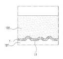
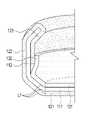
도 4는, 어떤 실시예에 따른, 액세서리의 일부 단면을 나타내는 사시도이다. 도 5는, 도 4에 도시된, 액세서리의 내측면을 바라본 모습을 나타내는 도면이다. 도 6은, 본 문서에 개시된 다양한 실시예들에 따른, 액세서리(예: 도 1의 100)의 일부 단면을 나타내는 사시도이다. 도 7은, 도 6에 도시된, 액세서리(예: 도 1의 100)의 내측면을 바라본 모습을 나타내는 도면이다. 본 문서에 개시된 다양한 실시예들에 따르면, 액세서리(100)의 오버랩 구조는 도 6 및 도 7에 도시되는 바와 같이 형성될 수 있다. 이에 대한 비교 실시예로서, 도 4 및 도 5가 도시될 수 있다.4 is a perspective view showing a partial cross-section of an accessory, according to some embodiments. FIG. 5 is a view showing the inner surface of the accessory shown in FIG. 4 . 6 is a perspective view illustrating a partial cross-section of an accessory (eg, 100 of FIG. 1 ) according to various embodiments disclosed herein. FIG. 7 is a view showing an inner surface of the accessory (eg, 100 in FIG. 1 ) shown in FIG. 6 . According to various embodiments disclosed herein, the overlap structure of the
도 4를 참조하면, 상기 제 2 평면부(131')의 단부가 상기 제 1 헤밍부(123')의 단부와 맞댄 모습이 도시될 수 있다. 여기서의 제 1 커버부재는 베이스 구조의 평면 상에서 제 2 커버부재와 만날 수 있다. 이에 따르면, 경계라인이 제품의 외관에 보다 잘 드러나게 될 수 있다. 따라서, 상기 제 1 헤밍부(123')의 단부에 보풀이 생길 경우, 제품 외관의 미려함이 저하될 수 있다. 도 5를 참조하면, 상기 제 2 평면부(131')의 단부가 상기 제 1 헤밍부(123')의 단부와 맞댄 모습이 도시될 수 있다. 도 4를 통해 전술한 바와 같이 상기 제 1 헤밍부(123')의 단부에 생긴 보풀(f)이 경계라인을 따라 외관에 잘 드러나게 될 수 있다.Referring to FIG. 4 , a state in which the end of the second flat portion 131' is in contact with the end of the first hemming portion 123' may be shown. Here, the first cover member may meet the second cover member on the plane of the base structure. According to this, the boundary line can be better revealed in the appearance of the product. Therefore, when fluff is generated at the end of the first hemming portion 123', the beauty of the product appearance may be deteriorated. Referring to FIG. 5 , a state in which the end of the second flat portion 131' is in contact with the end of the first hemming portion 123' may be shown. As described above with reference to FIG. 4 , the fluff f generated at the end of the first hemming portion 123' may be well exposed along the boundary line.
도 6을 참조하면, 제 2 엣지부(132)가 제 1 헤밍부(123)에 오버랩(overlap)될 수 있다. 상기 오버랩 구조는 사이드 멤버(112)의 내측면 상에 배치되므로, 액세서리(100)를 외부에서 볼 때, 경계라인이 잘 보이지 않게 될 수 있다. 도 6에 도시된 바와 같이 사이드 멤버(112)가 만곡된 경우에는 경계라인이 더욱 감춰지는 효과를 가질 수도 있다. 도 7을 참조하면, 액세서리(예: 도 1의 100)의 내측면, 즉 사이드 멤버(예: 도 1의 112)의 내측면을 바라본 모습이 도시된다. 다양한 실시예에 따르면, 상기 사이드 멤버(112)의 내측면을 제 1 헤밍부(123)가 커버하고 있고, 이 상태에서 제 2 엣지부(132)가 상기 제 1 헤밍부(123)에 오버랩(overlap)될 수 있다. 제 2 엣지부(132)의 단부는 제 3 라인(L3)을 따라 형성될 수 있고, 제 1 헤밍부(123)의 단부는 제 1 라인(L1) 또는 제 1-1라인(L1')을 따라 형성될 수 있다. 따라서, 제 1 헤밍부(123)의 적어도 일부분이 제 2 엣지부(132)의 적어도 일부분에 의해 오버랩(overlap)된 구조를 형성하게 될 수 있다. 이에 따르면, 제 1 헤밍부(123)의 단부에 보풀(예: 도 5의 f)이 생기더라도 외관에 드러나지 않고, 제 2 엣지부(132)에 의해 가려질 수 있다.Referring to FIG. 6 , the
도 8은, 본 문서에 개시된 다양한 실시예들에 따른, 액세서리(100)에 전자 장치(200)가 결합된 모습을 나타내는 정면도이다. 도 9는, 본 문서에 개시된 다양한 실시예들에 따른, 액세서리(100)에 전자 장치(200)의 결합된 모습을 나타내는 단면도이다. 도 9(a)는 도 8의 A-A'단면을 나타낼 수 있고, 도 9(b)는 도 8의 B1-B1'단면을 나타낼 수 있으며, 도 9(c)는 도 8의 B2-B2'단면을 나타낼 수 있다.8 is a front view illustrating a state in which the
다양한 실시예들에 따르면, 본 문서에 개시된 다양한 실시예들에 따른 액세서리(100)에는 다양한 형태의 전자 장치(200)가 장착될 수 있다.According to various embodiments, various types of
상기 전자 장치(200)는 다양한 형태의 장치가 해당될 수 있다. 전자 장치는, 예를 들면, 휴대용 통신 장치(예: 스마트폰(smartphone)), 태블릿 PC(tablet personal computer), 이동 전화기(mobile phone), 영상 전화기, 전자책 리더기(e-book reader), 데스크탑 PC(desktop personal computer), 랩탑 PC(laptop personal computer), 넷북 컴퓨터(netbook computer), 워크스테이션(workstation), 서버, PDA(personal digital assistant), PMP(portable multimedia player), MP3 플레이어, 모바일 의료기기, 카메라(camera), 또는 웨어러블 장치(wearable device) 중 적어도 하나를 포함할 수 있다. 다양한 실시예에 따르면, 웨어러블 장치는 액세서리형(예: 시계, 반지, 팔찌, 발찌, 목걸이, 안경, 콘택트 렌즈, 또는 머리 착용형 장치(head-mounted-device(HMD)), 직물 또는 의류 일체형(예: 전자 의복), 신체 부착형(예:스킨 패드(skin pad) 또는 문신), 또는 생체 이식형(예: implantable circuit) 중 적어도 하나를 포함할 수 있다.The
도 9(c)는 전자장치(200)가 장착된 액세서리(100)의 단면의 일부를 개념적으로 나타내는 것으로서, 도 9(c)를 참조하면, 전자 장치(200)의 중심으로부터 차례대로 제 2 엣지부(132), 제 1 헤밍부(123), 사이드 멤버(112) 및 제 1 엣지부(122)가 배치될 수 있다.9(c) conceptually shows a part of the cross section of the
도 9(c) 및 도 4를 함께 참조하면, 제 2 엣지부(132)가 제 2 평면부(예: 도 1의 131)로부터 일체로 연장 형성되는 경우에 있어서, 제 2 엣지부(132)는 사이드 멤버(112)의 내측면(111D)과 상기 제 1 헤밍부(123)의 형상에 대응하여 부분적으로 절곡될 수 있다. 상기 제 2 엣지부(132)의 적어도 일부는 상기 제 1 헤밍부(123)에 오버랩(overlap)될 수 있다.Referring to FIGS. 9(c) and 4 together, when the
다양한 실시예들에 따르면, 상기 제 1 헤밍부(123) 및 제 2 엣지부(132)의 오버랩 구조(또는 적층 구조)의 두께로 인해 액세서리(100)와 전자 장치(200) 사이에는 갭(g)이 형성될 수 있다. 도 9(a) 및 도 9(b)를 참조하면, 상기 갭(g)이 형성되지 않은 부분, 예를 들면, 사이드 멤버(예: 도 1의 112)의 단부와 사이드 멤버(예: 도 1의 112)와 플레이트(예: 도 1의 111)의 경계 부분에서는, 액세서리(100)와 전자 장치(200)는 면대 면(face to face)로 결합될 수 있다.According to various embodiments, there is a gap (g) between the accessory 100 and the
본 문서에 개시된 다양한 실시예들에 따르면, 상기 사이드 멤버(112)는 상기 갭(g)을 보상하도록 전체적으로 만곡될(curved) 수 있다. 한 실시예에 따르면, 도 8 및 도 9를 함께 참조하면, 사이드 멤버(112)의 단부에는 전자 장치(100)와 면대 면으로 접하는 체결 영역(C1, C2, C3)이 형성될 수 있다. 다양한 실시예들에 따르면 체결 영역(C1, C2, C3) 각각은 서로 동일한 각도로 만곡될 수 있으며, 서로 다른 각도를 갖도록 만곡될 수도 있다. 상기 체결 영역(C1, C2, C3)의 만곡되는 각도는 상기 갭(g)의 크기 또는 위치, 개구부(예: 도 2의 113)의 크기 또는 위치 등과 같은 파라미터에 따라 지정될 수 있다.According to various embodiments disclosed in this document, the
다양한 실시예들에 따르면, 상기 베이스 구조(예: 도 1의 110)에는 플레이트 홀(예: 도 1의 115)이 형성되고, 상기 제 1 커버부재(예: 도 1의 120)에는 상기 플레이트 홀(예: 도 1의 115)이 형성된 위치에 대응하여 제 1 홀(예: 도 1의 125)이 형성되며, 상기 제 2 커버부재(예: 도 1의 130)에는 상기 플레이트 홀(예: 도 1의 115)이 형성된 위치에 대응하여 제 2 홀(예: 도 1의 135)이 형성될 수 있다.According to various embodiments, a plate hole (eg, 115 in FIG. 1 ) is formed in the base structure (eg, 110 in FIG. 1 ), and the plate hole is formed in the first cover member (eg, 120 in FIG. 1 ). A first hole (eg, 125 in FIG. 1 ) is formed corresponding to the position where (eg, 115 in FIG. 1 ) is formed, and the plate hole (eg, 130 in FIG. 1 ) is formed with the plate hole (eg, in FIG. A second hole (eg, 135 in FIG. 1 ) may be formed corresponding to a position where 115 of 1) is formed.
상기 플레이트 홀(예: 도 1의 110)은 예를 들면, 카메라, 또는 각종 센서(예: 근접 센서, 지문 센서 등) 등이 노출되는 홀일 수 있다. 상기 플레이트 홀(예: 도 1의 110), 제 1 홀(예: 도 1의 125) 및 제 2 홀(예: 도 1의 135)를 구비하여, 액세서리(예: 도 1의 100)의 조립과정에서, 베이스 구조(예: 도 1의 110), 제 1 커버부재(예: 도 1의 120) 및 제 2 커버부재(예: 도 1의 130)의 정렬이 기 지정된 오차 범위 내에 있는지 여부를 판단할 수 있다.The plate hole (eg, 110 in FIG. 1 ) may be, for example, a hole through which a camera or various sensors (eg, a proximity sensor, a fingerprint sensor, etc.) are exposed. The plate hole (eg, 110 in FIG. 1 ), the first hole (eg, 125 in FIG. 1 ), and the second hole (eg, 135 in FIG. 1 ) are provided to assemble an accessory (eg, 100 in FIG. 1 ). In the process, whether or not the alignment of the base structure (eg 110 in FIG. 1 ), the first cover member (eg 120 in FIG. 1 ) and the second cover member (eg 130 in FIG. 1 ) is within a pre-specified error range. can judge
또, 다른 다양한 실시예들에 따르면, 상기 베이스 구조(예: 도 1의 110)에는 사이드 키 홀(예: 도 1의 116)을 형성할 수 있다. 상기 사이드 키 홀(예: 도 1의 116)이 형성하는 리세스(recess)에는 사이드 키 고정부(또는 사이드 키 입력 매개부, 미도시) 및 사이드 키(미도시)가 구비될 수 있다. 상기 제 1 커버부재(예: 도 1의 120)의 일측에는 상기 사이드 키에 대응하는 형상으로서 사이드 키 패턴부(미도시)가 볼록한 형태로 형성될 수 있다. 여기서의 사이드 키 고정부 및 사이드 키는 전자 장치(예: 도 200)의 하우징 또는 하우징 내부에 구비되는 사이드 키와 별개로 마련될 수 있다. 이들 실시예는, 사용자의 키 입력을 용이하게 하는 키 입력 장치의 보조수단으로 활용될 수 있다.Also, according to various other embodiments, a side key hole (eg, 116 in FIG. 1 ) may be formed in the base structure (eg, 110 in FIG. 1 ). A side key fixing part (or a side key input mediating part, not shown) and a side key (not shown) may be provided in a recess formed by the side key hole (eg, 116 in FIG. 1 ). A side key pattern portion (not shown) corresponding to the side key may be formed in a convex shape on one side of the first cover member (eg, 120 in FIG. 1 ). Here, the side key fixing part and the side key may be provided separately from the housing of the electronic device (eg, FIG. 200 ) or the side key provided inside the housing. These embodiments can be utilized as an auxiliary means of a key input device that facilitates a user's key input.
도 1 내지 도 9를 함께 참조하면, 본 문서에 개시된 다양한 실시예들에 따르면, 전자 장치(200)에 탈착 가능한 액세서리(100)를 제공할 수도 있다. 한 실시예에 따르면 여기서의 전자 장치는 일반 가전용 전자 장치에 비해 크기가 작고, 휴대 가능한 모바일(mobile) 전자 장치가 해당될 수 있다.Referring to FIGS. 1 to 9 together, according to various embodiments disclosed in this document, a
전자 장치(200)에 탈착 가능한 액세서리(100)는, 제 1 방향으로 향하는 전면(111A), 상기 제 1 방향의 반대인 제 2 방향으로 향하는 후면(111B)이 형성된 플레이트(111) 및 상기 전면(111A) 상에 전자 장치(200)가 안착되도록 형성된 공간을 둘러싸는 사이드 멤버(112)를 포함하는 베이스 구조(110)를 포함할 수 있다.The
다양한 실시예들에 따르면, 전자 장치(200)에 탈착 가능한 액세서리(100)는, 상기 후면(111B)을 포함한 상기 베이스 구조(110)의 적어도 일부 표면을 커버하고, 상기 후면(111B)을 마주보는 제 1 평면부(121), 상기 사이드 멤버(112)의 외측면(111C)을 마주보는 제 1 엣지부(122) 및 상기 사이드 멤버(112)의 내측면의 적어도 일부분을 마주보는 제 1 헤밍부(123)를 포함하며, 편물(knit)로 형성된 제 1 커버부재(120)를 더 포함할 수 있다.According to various embodiments, the
다양한 실시예들에 따르면, 전자 장치(200)에 탈착 가능한 액세서리(100)는,상기 전면(111A)을 포함한 상기 베이스 구조(110)의 적어도 일부 표면을 커버하고, 상기 전면(111A)을 마주보는 제 2 평면부(131), 상기 사이드 멤버(112)의 내측면의 적어도 일부분을 마주보고 상기 제 1 헤밍부(123)의 적어도 일부를 오버랩(overlap) 하도록 형성된 제 2 엣지부(132)를 포함하며, 상기 제 1 커버부재(120)와 다른 재질인 제 2 커버부재(130);를 더 포함할 수 있다.According to various embodiments, the
다양한 실시예들에 따르면, 전자 장치(200)에 탈착 가능한 액세서리(100)는,상기 사이드 멤버(112)에 상기 전자 장치의 입출력 장치가 형성되는 부분에 대응하기 위하여 개구부(113)가 형성되고, 상기 제 1 커버부재(120)와 일체로 형성되고, 상기 전면(111A)의 적어도 일부를 마주보고, 상기 개구부(113)에 대응하는 위치에 형성되며, 상기 제 2 평면부(131)의 일측의 단부와 맞닿는 단부를 가지는 제 2 헤밍부(124)를 포함할 수 있다.According to various embodiments, in the
상기한 실시예들에 따르면, 전자 장치(200)에 탈착 가능한 액세서리(100)에서, 제 1 커버부재(120)는 편물로 형성되고, 제 2 커버부재(130)는 편물과 다른 재질로 형성될 수 있다. 이때, 제 2 엣지부(132)의 적어도 일부분이 제 1 헤밍부(123)의 적어도 일부분을 오버랩(overlap)하도록 형성되고, 제 2 헤밍부(124)의 단부는 제 2 평면부(131)의 일측의 단부와 맞닿는 단부를 가지도록 형성될 수 있다. 이에 따르면, 편물을 사용하는 액세서리(100)에 있어서, 외관의 미려함을 저하시킬 수 있는 부분은 사이드 멤버(112)의 측면에 위치시킴으로써 시인성을 낮출 수 있고, 편물에 보풀이 생기더라도 오버랩 구조를 통해 가릴 수 있다. 또, 가공에 유리한 부분(예: 제 2 헤밍부(124))은 일 구성요소와 다른 구성요소의 오버랩 구조가 아닌, 일 구성요소의 단부면과 다른 구성요소의 단부면이 맞닿는 구조(이하, '1:1 맞춤구조'라 함)를 채용할 수 있다. 이에 따르면, 액세서리(100)의 제조 공정에 있어서, 오버랩 구조 또는 1:1 맞춤구조를 선택할 수 있다. 따라서, 제품 품질 향상은 물론 제품의 구조 및 공정 상황에 따라 특화된 공정을 적용할 수 있다.According to the above embodiments, in the
본 문서에 개시된 전자 장치(200)에 탈착 가능한 액세서리(100)를 설명함에 있어서, 전술한 실시예들과 중복되는 부분은 생략하기로 한다.In describing the
도 10은, 본 문서에 개시된 다양한 실시예들에 따른 액세서리(예: 도 1의 100)를 제조하는 방법에 있어서, 공정별 도면을 개략적으로 나타내는 도면이다. 도 11은, 본 문서에 개시된 다양한 실시예들에 따른, 액세서리(예: 도 1의 100)를 제조하는 방법을 나타내는 흐름도이다.FIG. 10 is a diagram schematically showing drawings for each process in a method of manufacturing an accessory (eg, 100 of FIG. 1 ) according to various embodiments disclosed in this document. 11 is a flowchart illustrating a method of manufacturing an accessory (eg, 100 of FIG. 1 ) according to various embodiments disclosed herein.
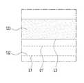
도 10(a)는 베이스 구조(110)에 제 1 커버부재(120)가 커버된 모습을 나타낼 수 있고, 도 10(b)는 베이스 구조(110)에 제 1 커버부재(120)가 커버된 상태에서 제 2 커버부재(130)가 추가로 커버된 모습을 나타낼 수 있다.10(a) may show a state in which the
도 10과 도 11을 함께 참조하면, 본 문서에 개시된 다양한 실시예들에 따른 액세서리(100)의 제조 방법은, 베이스 구조(110), 제 1 커버부재(120) 및 제 2 커버부재(130)를 준비하는 준비 공정(1101); 베이스 구조(110)에 제 1 커버부재(110)를 결합하는 제 1 결합 공정(1103); 제 1 커버부재(120)를 가공하는 공정(1105); 제베이스 구조(110)에 제 2 커버부재(130)를 결합하는 제 2 결합 공정(1107)을 포함할 수 있다. 다양한 실시예들에 따른, 액세서리(100) 제조 방법은 상기한 공정 이외에 열압착 공정(1109)을 포함할 수도 있다.10 and 11 together, a method of manufacturing an
상기 준비 공정(1101)은, 다양한 실시예들에 따르면, 플레이트(예: 도 1의111) 및 상기 플레이트(예: 도 1의 111)의 가장자리로부터 연장된 사이드 멤버(예: 도 1의 112)를 포함하는 베이스 구조(110), 편물(knit)로 형성된 제 1 커버부재(120), 및 상기 제 1 커버부재(120)와 다른 재질의 소재를 포함하는 제 2 커버부재(130)를 준비하는 공정을 포함할 수 있다.According to various embodiments, the
플레이트(예: 도 1의 111) 및 사이드 멤버(예: 도 1의 112)를 포함하는 베이스 구조(110)는, 예를 들면, 폴리카보네이트(polycarbonate, PC)와 같은 재료들을 사출시켜 만든 사출물일 수 있다. 제 1 커버부재(120)는, 예를 들면, 편물(knit)을 포함한 섬유 물질로서, 사용자에게 특유의 질감을 제공할 수 있다. 제 2 커버부재(130)는 편물(knit)을 포함한 상기 제 1 커버부재(120)와 다른 재질의 소재로 구성된 것으로서, 예컨대 직물(woven) 또는 부직포(Nonwoven)을 포함하는 섬유이거나, 폴리우레탄 등과 같은 비섬유 물질을 포함하는 소재일 수 있다. 상기 베이스 구조(100), 제 1 커버부재(120) 및 제 2 커버부재(130)는 서로 다른 재질의 물질로 제조될 수 있으며, 상기 재질은 액세서리(예: 도 1의 100)의 가공 시간, 가공 비용, 재료 비용, 마멸(friction and wear) 정도 등을 종합적으로 고려하여 다양하게 변형할 수 있다.The
다양한 실시예들에 따르면, 상기 제 1 커버부재(120)는 상기 베이스 구조(110)의 겉감을 구성할 수 있고, 상기 제 2 커버부재(130)는 상기 베이스 구조(110)의 안감을 구성할 수 있다. 한 실시예에 따르면, 상기 제 1 커버부재(120)가 제 2 커버부재(130)보다 큰 크기(또는 면적)로 형성될 수 있다.According to various embodiments, the
상기 제 1 결합 공정(1103)은, 다양한 실시예들에 따르면, 상기 베이스 구조(110)의 플레이트(예: 도 1의 111), 상기 사이드 멤버(예: 도 1의 112)의 외측면 (예: 도 1의 111C) 및 사이드 멤버(예: 도 1의 112)의 내측면(예: 도 1의 111D)의 적어도 일부분을 마주보도록, 상기 베이스 구조(110)에 상기 제 1 커버부재(120)를 커버하는 공정 및 상기 제 1 커버부재(120)의 적어도 일부가 상기 베이스 구조(110)에 결합(coupling)되는 공정을 포함할 수 있다.According to various embodiments, the
한 실시예에 따르면, 상기 제 1 결합 공정(1103)을 통해 상기 제 1 커버부재(120)의 제 1 평면부(예: 도 1의 121)의 전면(예: 도 1의 121A)이 플레이트(예: 도 1의 111)의 후면(예: 도 1의 111B)을 마주보도록 하고, 제 1 엣지부(예: 도 1의 122)가 사이드 멤버(112)의 외측면(예: 도 1의 111C)을 마주보도록 하며, 제 1 헤밍부(예: 도 1의 123)가 사이드 멤버(예: 도 1의 112)의 내측면(예: 도 1의 111D)을 마주보도록 할 수 있다. 이로써, 상기 제 1 커버부재(120)가 베이스 구조(110)의 외부 표면을 실질적으로 감싸게 될 수 있다.According to one embodiment, the front surface (eg, 121A in FIG. 1) of the first flat portion (eg, 121 in FIG. 1) of the
다양한 실시예들에 따르면, 상기 제 1 결합 공정(1103)에서, 상기 제 1 커버부재(120)의 각 구성요소와 베이스 구조(110)의 각 구성요소 간의 '결합'은 접합(conjugation), 부착(adhesion), 본딩(bonding) 등 모든 물리적인 연결을 의미할 수 있다. 예를 들면, 상기 상기 제 1 커버부재(120)의 각 구성요소와 베이스 구조(110)의 각 구성요소 간의 '결합'은 열 압착(thermo compression bonding)에 해당할 수 있다. 다양한 실시예에 따르면, 상기 제 1 결합 공정(1103)에서, 상기 제 1 커버부재(120)의 제 1 평면부(예: 도 1의 121)는 상기 플레이트(예: 도 1의 111)에 열압착될 수 있고, 상기 제 1 엣지부(예: 도 1의 122)는 사이드 멤버(112)의 외측면(예: 도 1의 111C)에 열압착될 수 있다. 상기 제 1 헤밍부(예: 도 1의 123)는 사이드 멤버(예: 도 1의 112)의 내측면(예: 도 1의 111D)을 마주보도록 할 수 있다.According to various embodiments, in the
다양한 실시예들에 따르면, 상기 제 1 결합 공정(1103)은, 제 1 커버부재(120) 및 베이스 구조(110) 사이에 간극이 발생하지 않도록 제 1 커버부재(120)를 스트레칭하는 공정을 포함할 수 있고, 상기 베이스 구조(110)의 외측면과 내측면의 각 모서리 부분을 열압착하는 공정을 포함할 수 있다.According to various embodiments, the
상기 제 1 커버부재(120)를 가공하는 공정(1105)은, 다양한 실시예들에 따르면, 상기 제 1 커버부재(120)의 적어도 일부를 컷팅하는 공정을 포함할 수 있다.According to various embodiments, the
다양한 실시예들에 따르면, 상기 제 1 커버부재(120)의 적어도 일부를 컷팅하는 공정은, 다양한 실시예들에 따르면, 상기 제 1 커버부재(120)를 베이스 구조(110)에 결합하기 전에 컷팅하는 공정과, 상기 제 1 커버부재(120)를 베이스 구조(110)에 결합한 후에 컷팅하는 공정을 포함할 수 있다. 제 1 커버부재(120)를 베이스 구조(110)에 결합하기 전에 컷팅하는 공정은 상기 제 1 커버부재(120)를 준비하는 공정에 중첩적으로 포함될 수도 있다.According to various embodiments, the process of cutting at least a portion of the
다양한 실시예들에 따르면, 제 1 커버부재(120)를 베이스 구조(110)에 결합한 후에 컷팅하는 공정은, 상기 제 1 커버부재(120)가 베이스 구조(110)에 결합된 후에 컷팅되는 공정일 수 있다. 예를 들면 제 1 커버부재(120)가 베이스 구조(110)에 결합된 후, 제 1 커버부재(120)의 적어도 일부분이 타발될 수 있다. 한 실시예에 따르면, 상기 타발은 프레스를 이용하여 제품의 형태를 가공하는 것일 수 있으며, 이하에서 설명하는 타발 공정은 프레스를 이용하여 제품을 펀칭(punching)하는 공정일 수 있다. 여기서 타발 공정은 소정의 금형 및 금형을 구동하는 제조 모듈 및 프로그램을 통해 수행될 수 있다.According to various embodiments, the process of cutting after coupling the
다양한 실시예들에 따르면, 상기 제 1 커버부재(120)를 가공하는 공정(1105)을 통해, 상기 제 1 커버부재(120)의 적어도 일부는 제거될 수 있다. 상기 제 1 커버부재(120)를 베이스 구조(110)에 결합한 다음, 상기 타발 공정을 통해 제 1 헤밍부(예: 도 1의 123)에서 잉여 부분을 제거할 수 있다. 여기서 잉여 부분 부분은, 예를 들면, 제 1 헤밍부(예: 도 1의 123)에서 제 1 라인(예: 도 1의 L1) 내부에 위치하며, 베이스 구조(110)의 전면(111A)에 맞닿는 부분일 수 있다. 또는 제 1 헤밍부(예: 도 1의 123)에서 제 1-1라인(예: 도 1의 L1') 내부에 위치하며, 베이스 구조(110)의 전면(111A)에 맞닿는 부분일 수 있다. 상기 타발 공정은 금형을 이용하여 수직 상방 또는 수직 하방으로 직선적으로 움직이므로 예컨대, 플라잉 컷 공정에 비해 경제적이고, 높은 공정 수율을 얻을 수 있다.According to various embodiments, at least a portion of the
상기 제 2 결합 공정(1107)은, 상기 베이스 구조(110)에 상기 제 2 커버부재(130)를 커버하는 공정; 및 상기 제 2 커버부재(130)의 적어도 일부가 상기 제 1 커버부재(120)의 적어도 일부에 오버랩(overlap)된 채로 결합(coupling)되는 공정;을 포함할 수 있다.The
한 실시예에 따르면, 상기 제 2 결합 공정(1107)을 통해 상기 제 2 커버부재(130)의 제 2 평면부(예: 도 1의 131)의 전면(예: 도 1의 131A)이 플레이트(예: 도 1의 111)의 전면(예: 도 1의 111A)을 마주보도록 하고, 제 2 엣지부(예: 도 1의 132)가 사이드 멤버(112)의 내측면(예: 도 1의 111D)을 마주보도록 할 수 있다. 이로써, 상기 제 1 커버부재(120)가 베이스 구조(110)의 내부 표면을 실질적으로 감싸게 될 수 있다. 여기서, 상기 제 2 엣지부(예: 도 1의 132)의 적어도 일부분이 상기 제 1 헤밍부(예: 도 1의 123)의 적어도 일부분에 오버랩(overlap)된 채로 결합될 수 있다.According to one embodiment, the front surface (eg, 131A in FIG. 1 ) of the second flat portion (eg, 131 in FIG. 1 ) of the
다양한 실시예들에 따르면, 상기 제 2 결합 공정(1107)에서, 상기 제 2 커버부재(130)의 각 구성요소와 베이스 구조(110) 간의 '결합'은 접합(conjugation), 부착(adhesion), 본딩(bonding) 등 모든 물리적인 연결을 의미할 수 있다.According to various embodiments, in the
도 11을 다시 참조하면, 본 문서에 개시된 다양한 실시예들에 따른 액세서리(예: 도 10의 100)를 제조하는 방법은 열압착 공정(1109)을 포함할 수 있다. 한 실시예에 따르면, 상기 제 2 커버부재(130)가 상기 베이스 구조(110)에 결합된 이후 열압착 공정을 통해, 결합된 구성을 고정시킬 수 있다. 또, 한 실시예에 따르면, 전술한 제 1 결합 공정(1103)에서 별도의 열압착 공정을 수행하지 아니하고, 상기 제 2 결합 공정(1107) 이후에 일괄적으로 열압착 공정을 수행할 수도 있다.Referring back to FIG. 11 , a method of manufacturing an accessory (eg, 100 of FIG. 10 ) according to various embodiments disclosed herein may include a
본 문서에 개시된 다양한 실시예들에 따르면, 상기 준비 공정(1103)에 있어서, 상기 베이스 구조(110)에 플레이트 홀(115)을 형성하는 공정; 상기 제 1 커버부재(120)에 제 1 홀(125)을 형성하는 공정; 및 상기 제 2 커버부재(130)에 제 2 홀(135)을 형성하는 공정;을 포함할 수 있다. 플레이트 홀(115), 제 1 홀(125) 및 제 2 홀(135)이 형성되면, 상기 제 1 커버부재(120)의 적어도 일부가 베이스 구조(110)에 결합(coupling)되는 공정에 있어서, 상기 플레이트 홀(115)과 제 1 홀(125)을 정렬시키는 공정을 수행할 수 있고, 상기 제 2 커버부재(130)의 적어도 일부가 제 1 커버부재(120)의 적어도 일부에 오버랩(overlap)된 채로 결합(coupling)되는 공정에 있어서, 상기 플레이트 홀(115)과 제 2 홀(135)을 정렬시키는 공정;을 수행할 수 있다. 이를 통해, 본 문서에 개시된 액세서리(예: 도 10의 100)의 결합과정에서 오 정렬을 방지할 수 있다.According to various embodiments disclosed herein, in the
본 문서의 다양한 실시예들 및 이에 사용된 용어들은 본 문서에 기재된 기술적 특징들을 특정한 실시예들로 한정하려는 것이 아니며, 해당 실시예의 다양한 변경, 균등물, 또는 대체물을 포함하는 것으로 이해되어야 한다. 도면의 설명과 관련하여, 유사한 또는 관련된 구성요소에 대해서는 유사한 참조 부호가 사용될 수 있다. 아이템에 대응하는 명사의 단수 형은 관련된 문맥상 명백하게 다르게 지시하지 않는 한, 상기 아이템 한 개 또는 복수 개를 포함할 수 있다. 본 문서에서, "A 또는 B", "A 및 B 중 적어도 하나", "A 또는 B 중 적어도 하나,""A, B 또는 C," "A, B 및 C 중 적어도 하나,"및 "A, B, 또는 C 중 적어도 하나"와 같은 문구들 각각은 그 문구들 중 해당하는 문구에 함께 나열된 항목들의 모든 가능한 조합을 포함할 수 있다. "제 1", "제 2", 또는 "첫째" 또는 "둘째"와 같은 용어들은 단순히 해당 구성요소를 다른 해당 구성요소와 구분하기 위해 사용될 수 있으며, 해당 구성요소들을 다른 측면(예: 중요성 또는 순서)에서 한정하지 않는다. 어떤(예: 제 1) 구성요소가 다른(예: 제 2) 구성요소에, "기능적으로" 또는 "통신적으로"라는 용어와 함께 또는 이런 용어 없이, "커플드" 또는 "커넥티드"라고 언급된 경우, 그것은 상기 어떤 구성요소가 상기 다른 구성요소에 직접적으로(예: 유선으로), 무선으로, 또는 제 3 구성요소를 통하여 연결될 수 있다는 것을 의미한다.Various embodiments of this document and terms used therein are not intended to limit the technical features described in this document to specific embodiments, but should be understood to include various modifications, equivalents, or substitutes of the embodiments. In connection with the description of the drawings, like reference numbers may be used for like or related elements. The singular form of a noun corresponding to an item may include one item or a plurality of items, unless the relevant context clearly dictates otherwise. In this document, "A or B", "at least one of A and B", "at least one of A or B," "A, B or C," "at least one of A, B and C," and "A Each of the phrases such as “at least one of , B, or C” may include all possible combinations of items listed together in the corresponding one of the phrases. Terms such as "first", "second", or "first" or "secondary" may simply be used to distinguish a given component from other corresponding components, and may be used to refer to a given component in another aspect (eg, importance or order) is not limited. A (e.g., first) component is said to be "coupled" or "connected" to another (e.g., second) component, with or without the terms "functionally" or "communicatively." When mentioned, it means that the certain component may be connected to the other component directly (eg by wire), wirelessly, or through a third component.
본 문서의 다양한 실시예들에서, 제조 방법과 관련된 동작들은 "액세서리 또는 전자 장치를 장착 가능한 액세서리"를 제조하기 위한 제조 모듈 또는 제조 프로그램을 이용하여 수행될 수 있다.In various embodiments of the present document, operations related to the manufacturing method may be performed using a manufacturing module or manufacturing program for manufacturing “accessories or accessories capable of attaching an electronic device”.
본 문서에서 사용된 용어 "모듈"은 하드웨어, 소프트웨어 또는 펌웨어로 구현된 유닛을 포함할 수 있으며, 예를 들면, 로직, 논리 블록, 부품, 또는 회로 등의 용어와 상호 호환적으로 사용될 수 있다. 모듈은, 일체로 구성된 부품 또는 하나 또는 그 이상의 기능을 수행하는, 상기 부품의 최소 단위 또는 그 일부가 될 수 있다. 예를 들면, 한 실시예에 따르면, 모듈은 ASIC(application-specific integrated circuit)의 형태로 구현될 수 있다.The term "module" used in this document may include a unit implemented by hardware, software, or firmware, and may be used interchangeably with terms such as logic, logic block, component, or circuit, for example. A module may be an integrally constructed component or a minimal unit of components or a portion thereof that performs one or more functions. For example, according to one embodiment, the module may be implemented in the form of an application-specific integrated circuit (ASIC).
다양한 실시예들에 따르면, 상기 기술한 구성요소들의 각각의 구성요소(예: 모듈 또는 프로그램)는 단수 또는 복수의 개체를 포함할 수 있다. 다양한 실시예들에 따르면, 전술한 해당 구성요소들 중 하나 이상의 구성요소들 또는 동작들이 생략되거나, 또는 하나 이상의 다른 구성요소들 또는 동작들이 추가될 수 있다. 대체적으로 또는 추가적으로, 복수의 구성요소들(예: 모듈 또는 프로그램)은 하나의 구성요소로 통합될 수 있다. 이런 경우, 통합된 구성요소는 상기 복수의 구성요소들 각각의 구성요소의 하나 이상의 기능들을 상기 통합 이전에 상기 복수의 구성요소들 중 해당 구성요소에 의해 수행되는 것과 동일 또는 유사하게 수행할 수 있다. 다양한 실시예들에 따르면, 모듈, 프로그램 또는 다른 구성요소에 의해 수행되는 동작들은 순차적으로, 병렬적으로, 반복적으로, 또는 휴리스틱하게 실행되거나, 상기 동작들 중 하나 이상이 다른 순서로 실행되거나, 생략되거나, 또는 하나 이상의 다른 동작들이 추가될 수 있다.According to various embodiments, each component (eg, module or program) of the components described above may include a singular entity or a plurality of entities. According to various embodiments, one or more components or operations among the aforementioned corresponding components may be omitted, or one or more other components or operations may be added. Alternatively or additionally, a plurality of components (eg modules or programs) may be integrated into a single component. In this case, the integrated component may perform one or more functions of each of the plurality of components identically or similarly to those performed by a corresponding component among the plurality of components prior to the integration. . According to various embodiments, the actions performed by a module, program, or other component are executed sequentially, in parallel, iteratively, or heuristically, or one or more of the actions are executed in a different order, or omitted. or one or more other actions may be added.
본 문서에 개시된 다양한 실시예들에 따르면, 제 1 방향으로 향하는 전면(111A), 상기 제 1 방향의 반대인 제 2 방향으로 향하는 후면(111B)이 형성된 플레이트(111) 및 상기 플레이트(111)의 가장자리로부터 연장된 사이드 멤버(112)를 포함하는 베이스 구조(110); 상기 후면(111B)을 포함한 상기 베이스 구조(110)의 적어도 일부 표면을 커버하는 제 1 커버부재(120)로서, 상기 후면(111B)을 마주보는 제 1 평면부(121), 상기 사이드 멤버(112)의 외측면을 마주보는 제 1 엣지부(122) 및 상기 사이드 멤버(112)의 내측면의 적어도 일부분을 마주보는 제 1 헤밍부(123)를 포함하는 제 1 커버부재(120); 및 상기 전면을 포함한 상기 베이스 구조의 적어도 일부 표면을 커버하는 제 2 커버부재(130)로서, 상기 전면(111A)을 마주보는 제 2 평면부(131), 상기 사이드 멤버의 내측면의 적어도 일부분을 마주보는 제 2 엣지부(132)를 포함하는 제 2 커버부재(130);를 포함하고, 상기 제 2 엣지부(132)의 적어도 일부분이 상기 제 1 헤밍부(123)의 적어도 일부분을 오버랩(overlap)하는 액세서리를 포함할 수 있다.According to various embodiments disclosed in this document, a
다양한 실시예들에 따르면, 상기 제 1 커버부재(120)는 편물(knit)을 포함하는 섬유로 구성될 수 있다.According to various embodiments, the
다양한 실시예들에 따르면, 상기 제 2 커버부재(130)는 상기 제 1 커버부재(120)와 다른 재질의 소재로 구성될 수 있다.According to various embodiments, the
다양한 실시예들에 따르면, 상기 제 2 엣지부(132)는 상기 제 1 헤밍부(123)와 압착되어 고정될 수 있다.According to various embodiments, the
다양한 실시예들에 따르면, 상기 사이드 멤버(112)의 일측에는 개구부(113)가 형성될 수 있다.According to various embodiments, an
다양한 실시예들에 따르면, 상기 사이드 멤버(112)에는 복수의 개구부(113)들이 형성될 수도 있다.According to various embodiments, a plurality of
다양한 실시예들에 따르면, 상기 제 1 커버부재(120)는, 상기 전면(111A)의 적어도 일부를 마주보며, 상기 개구부(113)에 대응하는 위치에 형성된 제 2 헤밍부(124)를 포함할 수 있다.According to various embodiments, the
다양한 실시예들에 따르면, 상기 제 2 헤밍부(124)의 일측의 단부는 상기 제 2 평면부(131)의 일측의 단부와 맞닿을 수 있다.According to various embodiments, an end of one side of the
다양한 실시예들에 따르면, 상기 제 2 헤밍부(124)의 일측의 단부 및 상기 제 2 평면부(131)의 일측의 단부는 동일한 높이를 가질 수 있다.According to various embodiments, an end of one side of the
다양한 실시예들에 따르면, 상기 제 2 헤밍부(124)는 상기 제 1 평면부(121)와 일체로 연장될 수 있다.According to various embodiments, the
다양한 실시예들에 따르면, 상기 제 1 헤밍부(123)는 상기 사이드 멤버(112)의 내측 모서리의 적어도 일부를 덮는 모서리부(123e)를 포함하며, 상기 모서리부(123e)는 상기 제 2 헤밍부(124)와 일체로 연결될 수 있다.According to various embodiments, the
다양한 실시예들에 따르면, 상기 모서리부(123e)에서 상기 제 2 엣지부(132)가 상기 제 1 엣지부(122)에 오버랩되는 폭은, 상기 제 1 헤밍부(124)에 가까워질 수록 점차적으로 감소될 수 있다.According to various embodiments, the width at which the
다양한 실시예들에 따르면, 상기 사이드 멤버(112) 및 상기 제 2 엣지부(132) 사이에는 갭(g)이 형성될 수 있다.According to various embodiments, a gap g may be formed between the
다양한 실시예들에 따르면, 상기 사이드 멤버(112)의 단부는 상기 갭(g)을 보상하도록 만곡될(curved) 수 있다.According to various embodiments, an end of the
다양한 실시예들에 따르면, 상기 베이스 구조에는 플레이트 홀(115)이 형성되고, 상기 제 1 커버부재(120)에는 상기 플레이트 홀(115)이 형성된 위치에 대응하여 제 1 홀(125)이 형성되며, 상기 제 2 커버부재(130)에는 상기 플레이트 홀(115)이 형성된 위치에 대응하여 제 2 홀(135)이 형성될 수 있다.According to various embodiments, a
본 문서에 개시된 다양한 실시예들에 따르면, 플레이트(111) 및 상기 플레이트(111)의 가장자리로부터 연장된 사이드 멤버(112)를 포함하는 베이스 구조(110), 편물(knit)로 형성된 제 1 커버부재(120), 및 상기 제 1 커버부재(120)와 다른 재질의 섬유로 구성된 제 2 커버부재(130)를 준비하는 공정; 상기 베이스 구조(110)의 플레이트(111), 상기 사이드 멤버(112)의 외측면 및 사이드 멤버(112)의 내측면의 적어도 일부분을 마주보도록, 상기 베이스 구조(110)에 상기 제 1 커버부재(110)를 커버하는 공정; 상기 제 1 커버부재(120)의 적어도 일부가 상기 베이스 구조(110)에 결합(coupling)되는 공정; 상기 제 1 커버부재(120)의 적어도 일부를 컷팅하는 공정; 상기 베이스 구조(110)에 상기 제 2 커버부재(130)를 커버하는 공정; 및 상기 제 2 커버부재(130)의 적어도 일부가 상기 제 1 커버부재(120)의 적어도 일부에 오버랩(overlap)된 채로 결합(coupling)되는 공정;을 포함하는 액세서리의 제조 방법을 제공할 수 있다.According to various embodiments disclosed in this document, a
다양한 실시예들에 따르면, 상기 제 1 커버부재(120)의 적어도 일부를 컷팅하는 공정은, 상기 플레이트(111)의 전면(111A)을 마주보는 제 1 커버부재(120)의 적어도 일부분을 타발(punching press)하는 공정을 포함할 수 있다.According to various embodiments, the process of cutting at least a portion of the
다양한 실시예들에 따르면, 상기 제 1 커버부재(120)의 적어도 일부가 베이스 구조(110)에 결합(coupling)되고, 상기 제 2 커버부재(130)의 적어도 일부가 제 1 커버부재(120)의 적어도 일부에 오버랩(overlap)된 채로 결합(coupling)되는 공정은, 열압착(hot pressing) 공정을 포함할 수 있다.According to various embodiments, at least a portion of the
다양한 실시예들에 따르면, 상기 베이스 구조(110), 상기 제 1 커버부재(120) 및 상기 제 2 커버부재(130)를 준비하는 공정에 있어서, 상기 베이스 구조(110)에 플레이트 홀(115)을 형성하는 공정; 상기 제 1 커버부재(120)에 제 1 홀(125)을 형성하는 공정; 및 상기 제 2 커버부재(130)에 제 2 홀(135)을 형성하는 공정;을 포함하고, 상기 제 1 커버부재(120)의 적어도 일부가 베이스 구조(110)에 결합(coupling)되는 공정에 있어서, 상기 플레이트 홀(115)과 제 1 홀(125)을 정렬시키는 공정; 및 상기 제 2 커버부재(130)의 적어도 일부가 제 1 커버부재(120)의 적어도 일부에 오버랩(overlap)된 채로 결합(coupling)되는 공정에 있어서, 상기 플레이트 홀(115)과 제 2 홀(135)을 정렬시키는 공정;을 포함할 수 있다.According to various embodiments, in the process of preparing the
본 문서에 개시된 다양한 실시예들에 따르면, 제 1 방향으로 향하는 전면(111A), 상기 제 1 방향의 반대인 제 2 방향으로 향하는 후면(111B)이 형성된 플레이트(111) 및 상기 전면(111A) 상에 전자 장치(200)가 안착되도록 형성된 공간을 둘러싸는 사이드 멤버(112)를 포함하는 베이스 구조(110); 상기 후면(111B)을 포함한 상기 베이스 구조(110)의 적어도 일부 표면을 커버하는 제 1 커버부재(120)로서, 상기 후면(111B)을 마주보는 제 1 평면부(131), 상기 사이드 멤버(112)의 외측면(111C)을 마주보는 제 1 엣지부(122) 및 상기 사이드 멤버(112)의 내측면의 적어도 일부분을 마주보는 제 1 헤밍부(123)를 포함하며, 편물(knit)로 형성된 제 1 커버부재(120); 및 상기 전면(111A)을 포함한 상기 베이스 구조(110)의 적어도 일부 표면을 커버하는 제 2 커버부재(130)로서, 상기 전면(111A)을 마주보는 제 2 평면부(131), 상기 사이드 멤버(112)의 내측면의 적어도 일부분을 마주보고 상기 제 1 헤밍부(123)의 적어도 일부를 오버랩(overlap) 하도록 형성된 제 2 엣지부(132)를 포함하며, 상기 제 1 커버부재(120)와 다른 재질인 제 2 커버부재(130);를 포함하고, 상기 사이드 멤버(112)에는 상기 전자 장치의 입출력 장치가 형성되는 부분에 대응하기 위하여 개구부(113)가 형성되고,상기 제 1 커버부재(120)와 일체로 형성되고, 상기 전면(111A)의 적어도 일부를 마주보고, 상기 개구부(113)에 대응하는 위치에 형성되는 제 2 헤밍부(124)로서, 상기 제 2 평면부(131)의 일측의 단부와 맞닿는 단부를 가지는 제 2 헤밍부(124)를 포함하는 전자 장치에 탈착 가능한 액세서리를 제공할 수 있다.According to various embodiments disclosed in this document, a
다양한 실시예들에 따르면, 상기 전자 장치에 탈착 가능한 액세서리는 상기 제 2 헤밍부(124)의 일측의 단부 및 상기 제 2 평면부(131)의 일측의 단부가 동일한 높이를 가질 수 있다.According to various embodiments, in the accessory detachable from the electronic device, one end of the
본 문서에 개시된 실시예는 개시된, 기술 내용의 설명 및 이해를 위해 제시된 것이며, 본 문서에서 기재된 기술의 범위를 한정하는 것은 아니다. 따라서, 본 문서의 범위는, 본 문서의 기술적 사상에 근거한 모든 변경 또는 다양한 다른 실시예를 포함하는 것으로 해석되어야 한다.The embodiments disclosed in this document are presented for explanation and understanding of the disclosed technical content, and do not limit the scope of the technology described in this document. Therefore, the scope of this document should be construed as including all changes or various other embodiments based on the technical idea of this document.
100 : 액세서리
110 : 베이스 구조
111 : 플레이트
112 : 사이드 멤버
113 : 개구
115 : 플레이트 홀
116 : 사이드 키 홀
120 : 제 1 커버부재(또는 겉감, first covering material)
121 : 제 1 평면부
122 : 제 1 엣지부
123 : 제 1 헤밍부
124 : 제 2 헤밍부
125 : 제 1 홀
130 : 제 2 커버부재(또는 안감, second covering material)
131 : 제 2 평면부
132 : 제 2 엣지부
135 : 제 2 홀
200 : 전자 장치100: accessories
110: base structure
111: plate
112: side member
113: opening
115: plate hole
116: side key hole
120: first covering member (or first covering material)
121: first flat part
122: first edge portion
123: first hemming part
124: second hemming part
125: 1st hole
130: second cover member (or lining, second covering material)
131: second flat part
132: second edge portion
135: 2nd hole
200: electronic device
Claims (20)
Translated fromKorean제 1 방향으로 향하는 전면, 상기 제 1 방향의 반대인 제 2 방향으로 향하는 후면이 형성된 플레이트 및 상기 플레이트의 가장자리로부터 연장된 사이드 멤버를 포함하는 베이스 구조;
상기 후면을 포함한 상기 베이스 구조의 적어도 일부 표면을 커버하는 제 1 커버부재로서, 상기 후면을 마주보는 제 1 평면부, 상기 사이드 멤버의 외측면을 마주보는 제 1 엣지부 및 상기 사이드 멤버의 내측면의 적어도 일부분을 마주보는 제 1 헤밍부를 포함하는 제 1 커버부재; 및
상기 전면을 포함한 상기 베이스 구조의 적어도 일부 표면을 커버하는 제 2 커버부재로서, 상기 전면을 마주보는 제 2 평면부, 상기 사이드 멤버의 내측면의 적어도 일부분을 마주보는 제 2 엣지부를 포함하는 제 2 커버부재;를 포함하고,
상기 제 2 엣지부의 적어도 일부분이 상기 제 1 헤밍부의 적어도 일부분을 오버랩(overlap)하는 액세서리.As for accessories,
a base structure including a plate having a front surface facing a first direction and a rear surface facing a second direction opposite to the first direction, and side members extending from edges of the plate;
A first cover member covering at least a portion of the surface of the base structure including the rear surface, comprising: a first flat part facing the rear surface, a first edge part facing the outer surface of the side member, and an inner surface of the side member A first cover member including a first hemming portion facing at least a portion of the; and
A second cover member covering at least a portion of the surface of the base structure including the front surface, including a second plane portion facing the front surface and a second edge portion facing at least a portion of an inner surface of the side member. Including; cover member;
An accessory wherein at least a portion of the second edge portion overlaps at least a portion of the first hemming portion.
상기 제 1 커버부재는 편물(knit)을 포함하는 섬유로 구성되는 액세서리.According to claim 1,
The accessory of claim 1 , wherein the first cover member is composed of fibers including a knitted fabric.
상기 제 2 커버부재는 상기 제 1 커버부재와 다른 재질의 소재로 구성되는 액세서리.According to claim 1,
The second cover member is an accessory made of a material different from that of the first cover member.
상기 제 2 엣지부는 상기 제 1 헤밍부와 압착되어 고정되는 액세서리.According to claim 1,
The second edge portion is fixed by being compressed with the first hemming portion.
상기 사이드 멤버의 일측에는 개구부가 형성되는 액세서리.According to claim 1,
An accessory having an opening formed on one side of the side member.
상기 사이드 멤버에는 복수의 개구부가 형성되는 액세서리.According to claim 5,
An accessory having a plurality of openings formed in the side member.
상기 제 1 커버부재는, 상기 전면의 적어도 일부를 마주보며, 상기 개구부에 대응하는 위치에 형성된 제 2 헤밍부를 포함하는 액세서리.According to claim 5,
The first cover member includes a second hemming portion facing at least a portion of the front surface and formed at a position corresponding to the opening.
상기 제 2 헤밍부의 일측의 단부는 상기 제 2 평면부의 일측의 단부와 맞닿는 액세서리.According to claim 7,
An accessory of claim 1, wherein an end portion of one side of the second hemming portion abuts against an end portion of one side of the second flat portion.
상기 제 2 헤밍부의 일측의 단부 및 상기 제 2 평면부의 일측의 단부는 동일한 높이를 가지는 액세서리.According to claim 8,
An end of one side of the second hemming portion and an end of one side of the second flat portion have the same height.
상기 제 2 헤밍부는 상기 제 1 평면부와 일체로 연장되는 액세서리.According to claim 7,
The second hemming portion extends integrally with the first flat portion.
상기 제 1 헤밍부는 상기 사이드 멤버의 내측 모서리의 적어도 일부를 덮는 모서리부를 포함하며, 상기 모서리부는 상기 제 2 헤밍부와 일체로 연결되는 액세서리.According to claim 7,
The first hemming part includes a corner part covering at least a part of an inner edge of the side member, and the corner part is integrally connected to the second hemming part.
상기 모서리부에서 제 2 엣지부가 상기 제 1 엣지부에 오버랩되는 폭은, 상기 제 1 헤밍부에 가까워질 수록 점차적으로 감소되는 액세서리.According to claim 11,
An accessory in which a width in which the second edge portion overlaps the first edge portion in the corner portion gradually decreases as the first hemming portion approaches.
상기 사이드 멤버 및 상기 제 2 엣지부 사이에는 갭이 형성되는 액세서리.According to claim 1,
An accessory in which a gap is formed between the side member and the second edge portion.
상기 사이드 멤버는 상기 갭을 보상하도록 만곡되는(curved) 액세서리.According to claim 13,
The accessory of claim 1 , wherein the side member is curved to compensate for the gap.
상기 베이스 구조에는 플레이트 홀이 형성되고, 상기 제 1 커버부재에는 상기 플레이트 홀이 형성된 위치에 대응하여 제 1 홀이 형성되며, 상기 제 2 커버부재에는 상기 플레이트 홀이 형성된 위치에 대응하여 제 2 홀이 형성되는 액세서리.According to claim 1,
A plate hole is formed in the base structure, a first hole is formed in the first cover member corresponding to the position where the plate hole is formed, and a second hole is formed in the second cover member corresponding to the position where the plate hole is formed. accessories from which it is formed.
플레이트 및 상기 플레이트의 가장자리로부터 연장된 사이드 멤버를 포함하는 베이스 구조, 편물(knit)로 형성된 제 1 커버부재, 및 상기 제 1 커버부재와 다른 재질의 소재로 구성된 제 2 커버부재를 준비하는 공정;
상기 베이스 구조의 플레이트, 상기 사이드 멤버의 외측면 및 사이드 멤버의 내측면의 적어도 일부분을 마주보도록, 상기 베이스 구조에 상기 제 1 커버부재를 커버하는 공정;
상기 제 1 커버부재의 적어도 일부가 상기 베이스 구조에 결합(coupling)되는 공정;
상기 제 1 커버부재의 적어도 일부를 컷팅하는 공정;
상기 베이스 구조에 상기 제 2 커버부재를 커버하는 공정; 및
상기 제 2 커버부재의 적어도 일부가 상기 제 1 커버부재의 적어도 일부에 오버랩(overlap)된 채로 결합(coupling)되는 공정;을 포함하는 액세서리의 제조 방법.In the manufacturing method of the accessory,
preparing a base structure including a plate and side members extending from edges of the plate, a first cover member formed of a knitted fabric, and a second cover member made of a material different from that of the first cover member;
covering the first cover member on the base structure so that at least a portion of the plate of the base structure, the outer surface of the side member and the inner surface of the side member face each other;
coupling at least a portion of the first cover member to the base structure;
cutting at least a portion of the first cover member;
covering the second cover member on the base structure; and
A method of manufacturing an accessory including a step of coupling at least a portion of the second cover member while overlapping with at least a portion of the first cover member.
상기 제 1 커버부재의 적어도 일부를 컷팅하는 공정은,
상기 플레이트의 전면을 마주보는 제 1 커버부재의 적어도 일부분을 타발(punching press)하는 공정을 포함하는 액세서리의 제조 방법.17. The method of claim 16,
The process of cutting at least a portion of the first cover member,
A method of manufacturing an accessory comprising a step of punching at least a portion of a first cover member facing the front surface of the plate.
상기 제 1 커버부재의 적어도 일부가 베이스 구조에 결합(coupling)되고, 상기 제 2 커버부재의 적어도 일부가 제 1 커버부재의 적어도 일부에 오버랩(overlap)된 채로 결합(coupling)되는 공정은, 열압착(hot pressing) 공정을 포함하는 액세서리의 제조 방법.17. The method of claim 16,
In the process of coupling at least a portion of the first cover member to the base structure and coupling at least a portion of the second cover member while overlapping with at least a portion of the first cover member, the heat A method of manufacturing an accessory comprising a hot pressing process.
상기 베이스 구조, 상기 제 1 커버부재 및 상기 제 2 커버부재를 준비하는 공정에 있어서, 상기 베이스 구조에 플레이트 홀을 형성하는 공정; 상기 제 1 커버부재에 제 1 홀을 형성하는 공정; 및 상기 제 2 커버부재에 제 2 홀을 형성하는 공정;을 포함하고,
상기 제 1 커버부재의 적어도 일부가 베이스 구조에 결합(coupling)되는 공정에 있어서, 상기 플레이트 홀과 제 1 홀을 정렬시키는 공정; 및
상기 제 2 커버부재의 적어도 일부가 제 1 커버부재의 적어도 일부에 오버랩된 채로 결합(coupling)되는 공정에 있어서, 상기 플레이트 홀과 제 2 홀을 정렬시키는 공정;을 포함하는 액세서리의 제조 방법.According to claim 16,
In the step of preparing the base structure, the first cover member, and the second cover member, forming a plate hole in the base structure; forming a first hole in the first cover member; and forming a second hole in the second cover member.
In the process of coupling at least a part of the first cover member to the base structure, the process of aligning the plate hole and the first hole; and
In the step of coupling at least a portion of the second cover member while overlapping at least a portion of the first cover member, the step of aligning the plate hole and the second hole; manufacturing method of an accessory comprising a.
제 1 방향으로 향하는 전면, 상기 제 1 방향의 반대인 제 2 방향으로 향하는 후면이 형성된 플레이트 및 상기 전면 상에 전자 장치가 안착되도록 형성된 공간을 둘러싸는 사이드 멤버를 포함하는 베이스 구조;
상기 후면을 포함한 상기 베이스 구조의 적어도 일부 표면을 커버하는 제 1 커버부재로서, 상기 후면을 마주보는 제 1 평면부, 상기 사이드 멤버의 외측면을 마주보는 제 1 엣지부 및 상기 사이드 멤버의 내측면의 적어도 일부분을 마주보는 제 1 헤밍부를 포함하며, 편물(knit)로 형성된 제 1 커버부재; 및
상기 전면을 포함한 상기 베이스 구조의 적어도 일부 표면을 커버하는 제 2 커버부재로서, 상기 전면을 마주보는 제 2 평면부, 상기 사이드 멤버의 내측면의 적어도 일부분을 마주보고 상기 제 1 헤밍부의 적어도 일부를 오버랩(overlap) 하도록 형성된 제 2 엣지부를 포함하며, 상기 제 1 커버부재와 다른 재질인 제 2 커버부재;를 포함하고,
상기 사이드 멤버에는 상기 전자 장치의 입출력 장치가 형성되는 부분에 대응하기 위하여 개구부가 형성되고,
상기 제 1 커버부재와 일체로 형성되고, 상기 전면의 적어도 일부를 마주보고, 상기 개구부에 대응하는 위치에 형성되는 제 2 헤밍부로서, 상기 제 2 평면부의 일측의 단부와 맞닿는 단부를 가지는 제 2 헤밍부를 포함하는 전자 장치에 탈착 가능한 액세서리.
In an accessory detachable to an electronic device,
a base structure including a plate having a front surface facing a first direction, a rear surface facing a second direction opposite to the first direction, and a side member enclosing a space formed on the front surface to accommodate an electronic device;
A first cover member covering at least a portion of the surface of the base structure including the rear surface, comprising: a first flat part facing the rear surface, a first edge part facing the outer surface of the side member, and an inner surface of the side member A first cover member including a first hemming portion facing at least a portion of the first cover member formed of a knitted fabric; and
A second cover member covering at least a portion of the surface of the base structure including the front surface, a second flat portion facing the front surface, and at least a portion of the first hemming portion facing at least a portion of the inner surface of the side member. A second cover member including a second edge portion formed to overlap and made of a material different from that of the first cover member;
An opening is formed in the side member to correspond to a portion where an input/output device of the electronic device is formed,
A second hemming portion integrally formed with the first cover member, facing at least a portion of the front surface, and formed at a position corresponding to the opening, having an end portion in contact with an end portion of one side of the second flat portion. A detachable accessory to an electronic device that includes a hemming portion.
Priority Applications (3)
| Application Number | Priority Date | Filing Date | Title |
|---|---|---|---|
| KR1020180021990AKR102479640B1 (en) | 2018-02-23 | 2018-02-23 | Accessory and manufacturing method thereof |
| US16/971,437US11812829B2 (en) | 2018-02-23 | 2018-12-10 | Accessory and manufacturing method therefor |
| PCT/KR2018/015625WO2019164109A1 (en) | 2018-02-23 | 2018-12-10 | Accessory and manufacturing method therefor |
Applications Claiming Priority (1)
| Application Number | Priority Date | Filing Date | Title |
|---|---|---|---|
| KR1020180021990AKR102479640B1 (en) | 2018-02-23 | 2018-02-23 | Accessory and manufacturing method thereof |
Publications (2)
| Publication Number | Publication Date |
|---|---|
| KR20190101688A KR20190101688A (en) | 2019-09-02 |
| KR102479640B1true KR102479640B1 (en) | 2022-12-22 |
Family
ID=67687611
Family Applications (1)
| Application Number | Title | Priority Date | Filing Date |
|---|---|---|---|
| KR1020180021990AActiveKR102479640B1 (en) | 2018-02-23 | 2018-02-23 | Accessory and manufacturing method thereof |
Country Status (3)
| Country | Link |
|---|---|
| US (1) | US11812829B2 (en) |
| KR (1) | KR102479640B1 (en) |
| WO (1) | WO2019164109A1 (en) |
Citations (4)
| Publication number | Priority date | Publication date | Assignee | Title |
|---|---|---|---|---|
| KR101084548B1 (en) | 2011-08-24 | 2011-11-17 | 이명호 | Shield case and its manufacturing method |
| US20160058146A1 (en) | 2014-09-03 | 2016-03-03 | Apple Inc. | Case for a portable electronic device |
| US20170187853A1 (en) | 2014-05-30 | 2017-06-29 | Samsonite IP Holdings S.àr.l | Protective Cover for an Electronic Device Including Impact Geometry |
| US20170248992A1 (en) | 2016-02-25 | 2017-08-31 | Microsoft Technology Licensing, Llc | Systems and apparatus for housing electronic components and methods thereof |
Family Cites Families (23)
| Publication number | Priority date | Publication date | Assignee | Title |
|---|---|---|---|---|
| US8782812B2 (en) | 2006-05-23 | 2014-07-22 | Bha Altair, Llc | Waterproof breathable garment with tape-free seams |
| KR100941830B1 (en)* | 2007-05-03 | 2010-02-11 | 유명기 | Electronic case and manufacturing method |
| KR101047864B1 (en) | 2008-01-10 | 2011-07-15 | (주)티 에스 에이 콜렉션 | Fabric Connection and Connection Method |
| US8367235B2 (en)* | 2008-01-18 | 2013-02-05 | Mophie, Inc. | Battery pack, holster, and extendible processing and interface platform for mobile devices |
| KR101504207B1 (en)* | 2008-09-22 | 2015-03-19 | 엘지전자 주식회사 | Case for portable terminal, portable terminal having the same and method for manufacturing the same |
| US7782610B2 (en)* | 2008-11-17 | 2010-08-24 | Incase Designs Corp. | Portable electronic device case with battery |
| US9281858B2 (en)* | 2014-01-03 | 2016-03-08 | Incipio, Llc | Co-molded multi-layered protective case for mobile device |
| US20200295795A1 (en)* | 2014-01-03 | 2020-09-17 | Incipio, Llc | Co-molded multi-layered protective case for mobile device |
| US8457701B2 (en)* | 2010-06-16 | 2013-06-04 | Incase Designs Corp. | Case for portable electronic device |
| KR101249027B1 (en)* | 2010-09-17 | 2013-03-29 | 나현주 | Protecting case for a portable device |
| US9294601B2 (en)* | 2011-05-23 | 2016-03-22 | Alexander H Hammond | Illuminated cell phone case |
| WO2012170892A2 (en)* | 2011-06-09 | 2012-12-13 | Skinit, Inc. | Method and apparatus for personalizing consumer products |
| WO2013012963A1 (en)* | 2011-07-18 | 2013-01-24 | G-Form, LLC | Configurable protective cover, method of making and method of using |
| US9300347B1 (en)* | 2012-04-18 | 2016-03-29 | Star Co Scientific Technologies Advanced Research Co, Llc | Active cover for electronic device |
| US9469469B2 (en)* | 2012-06-01 | 2016-10-18 | Treefrog Developments, Inc. | Housing for encasing an object having a thin profile |
| US8716598B2 (en)* | 2012-08-23 | 2014-05-06 | Octo Products LLC | Case for housing and protecting an electronic device |
| WO2014150555A1 (en)* | 2013-03-15 | 2014-09-25 | Mophie, Inc. | Protective case for mobile device |
| US9307816B2 (en) | 2013-09-04 | 2016-04-12 | Apple Inc. | Accessory covers for mobile phones or other consumer electronic devices |
| US10509443B2 (en)* | 2015-09-18 | 2019-12-17 | Toray Industries, Inc. | Housing |
| US10542802B1 (en)* | 2015-10-26 | 2020-01-28 | Incase Designs Corp. | Case for portable electronic device |
| KR102660537B1 (en)* | 2016-07-19 | 2024-04-26 | 삼성디스플레이 주식회사 | Display apparatus |
| KR102344763B1 (en)* | 2017-06-19 | 2021-12-29 | 삼성디스플레이 주식회사 | Panel bottom sheet and display including the same |
| KR102403879B1 (en)* | 2017-07-07 | 2022-05-31 | 삼성디스플레이 주식회사 | Protection film, window including the same and method for fabricating display device |
- 2018
- 2018-02-23KRKR1020180021990Apatent/KR102479640B1/enactiveActive
- 2018-12-10USUS16/971,437patent/US11812829B2/enactiveActive
- 2018-12-10WOPCT/KR2018/015625patent/WO2019164109A1/ennot_activeCeased
Patent Citations (4)
| Publication number | Priority date | Publication date | Assignee | Title |
|---|---|---|---|---|
| KR101084548B1 (en) | 2011-08-24 | 2011-11-17 | 이명호 | Shield case and its manufacturing method |
| US20170187853A1 (en) | 2014-05-30 | 2017-06-29 | Samsonite IP Holdings S.àr.l | Protective Cover for an Electronic Device Including Impact Geometry |
| US20160058146A1 (en) | 2014-09-03 | 2016-03-03 | Apple Inc. | Case for a portable electronic device |
| US20170248992A1 (en) | 2016-02-25 | 2017-08-31 | Microsoft Technology Licensing, Llc | Systems and apparatus for housing electronic components and methods thereof |
Also Published As
| Publication number | Publication date |
|---|---|
| US20200397106A1 (en) | 2020-12-24 |
| WO2019164109A1 (en) | 2019-08-29 |
| KR20190101688A (en) | 2019-09-02 |
| US11812829B2 (en) | 2023-11-14 |
Similar Documents
| Publication | Publication Date | Title |
|---|---|---|
| EP3054657B1 (en) | Electronic device with cover | |
| CN105897962B (en) | Electronic device with cover | |
| CN106233363B (en) | Curved body and wearable device with the same | |
| US11188120B2 (en) | Foldable electronic device | |
| EP3483783B1 (en) | Display device | |
| KR102692443B1 (en) | electronic device including biometric sensor | |
| KR102383702B1 (en) | Electronic device and manufacturing method for housing of the same | |
| US11292651B2 (en) | Protective film attachable to electronic device, and protective film package including same | |
| US10331170B2 (en) | Component assembly in pre bent state | |
| KR102611125B1 (en) | Electronic device with curved window | |
| EP4246248A1 (en) | Strap structure connected to housing, and wearable electronic device comprising same | |
| KR20210037092A (en) | Electronic Device including a sensor which is disposed below a display | |
| KR102479640B1 (en) | Accessory and manufacturing method thereof | |
| KR102524831B1 (en) | electronic device including window | |
| KR102512848B1 (en) | Glass molding apparatus and molding molding method thereof | |
| US20230333601A1 (en) | Electronic device including fixing member | |
| EP3554058A1 (en) | Mobile phone housing with a leather card holder | |
| EP4286345A1 (en) | Transparent member, electronic device comprising same, and method for thermoforming transparent member | |
| KR20210080690A (en) | Electronic device including adhesion part | |
| KR102556870B1 (en) | Watch band with braided strands | |
| CN106455379B (en) | Electronic equipment shell | |
| KR20230034746A (en) | Protection structure for display and electronic device including thereof | |
| CN217279290U (en) | Main structure of wearable equipment and wearable equipment | |
| KR20180096641A (en) | Protection | |
| CN109286697B (en) | Mobile Terminal |
Legal Events
| Date | Code | Title | Description |
|---|---|---|---|
| PA0109 | Patent application | St.27 status event code:A-0-1-A10-A12-nap-PA0109 | |
| PG1501 | Laying open of application | St.27 status event code:A-1-1-Q10-Q12-nap-PG1501 | |
| A201 | Request for examination | ||
| PA0201 | Request for examination | St.27 status event code:A-1-2-D10-D11-exm-PA0201 | |
| E701 | Decision to grant or registration of patent right | ||
| PE0701 | Decision of registration | St.27 status event code:A-1-2-D10-D22-exm-PE0701 | |
| PR0701 | Registration of establishment | St.27 status event code:A-2-4-F10-F11-exm-PR0701 | |
| PR1002 | Payment of registration fee | St.27 status event code:A-2-2-U10-U11-oth-PR1002 Fee payment year number:1 | |
| PG1601 | Publication of registration | St.27 status event code:A-4-4-Q10-Q13-nap-PG1601 | |
| P22-X000 | Classification modified | St.27 status event code:A-4-4-P10-P22-nap-X000 |