KR102479311B1 - System and method for instrument disturbance compensation - Google Patents
System and method for instrument disturbance compensationDownload PDFInfo
- Publication number
- KR102479311B1 KR102479311B1KR1020177003481AKR20177003481AKR102479311B1KR 102479311 B1KR102479311 B1KR 102479311B1KR 1020177003481 AKR1020177003481 AKR 1020177003481AKR 20177003481 AKR20177003481 AKR 20177003481AKR 102479311 B1KR102479311 B1KR 102479311B1
- Authority
- KR
- South Korea
- Prior art keywords
- joints
- computer
- joint
- point
- interest
- Prior art date
- Legal status (The legal status is an assumption and is not a legal conclusion. Google has not performed a legal analysis and makes no representation as to the accuracy of the status listed.)
- Active
Links
- 238000000034methodMethods0.000titleclaimsdescription116
- 230000033001locomotionEffects0.000claimsabstractdescription225
- 239000012636effectorSubstances0.000claimsdescription74
- 230000000670limiting effectEffects0.000claimsdescription4
- 210000001503jointAnatomy0.000description155
- 230000009466transformationEffects0.000description85
- 230000000875corresponding effectEffects0.000description79
- 230000008569processEffects0.000description53
- 238000003384imaging methodMethods0.000description39
- 230000008859changeEffects0.000description19
- 238000000844transformationMethods0.000description18
- 238000010586diagramMethods0.000description15
- 230000001276controlling effectEffects0.000description12
- 238000013519translationMethods0.000description8
- 238000000429assemblyMethods0.000description7
- 230000000712assemblyEffects0.000description7
- 230000006378damageEffects0.000description7
- 238000003780insertionMethods0.000description7
- 230000037431insertionEffects0.000description7
- 238000001356surgical procedureMethods0.000description7
- 238000012937correctionMethods0.000description6
- 210000000323shoulder jointAnatomy0.000description6
- 238000012986modificationMethods0.000description5
- 230000004048modificationEffects0.000description5
- 210000003857wrist jointAnatomy0.000description5
- 238000004364calculation methodMethods0.000description4
- 239000011159matrix materialSubstances0.000description4
- 230000003094perturbing effectEffects0.000description4
- 208000027418Wounds and injuryDiseases0.000description3
- 238000004891communicationMethods0.000description3
- 230000000694effectsEffects0.000description3
- 208000014674injuryDiseases0.000description3
- 230000002829reductive effectEffects0.000description3
- 241001631457CannulaSpecies0.000description2
- 238000002679ablationMethods0.000description2
- 238000006243chemical reactionMethods0.000description2
- 230000001447compensatory effectEffects0.000description2
- 239000002131composite materialSubstances0.000description2
- 230000008878couplingEffects0.000description2
- 238000010168coupling processMethods0.000description2
- 238000005859coupling reactionMethods0.000description2
- 238000013461designMethods0.000description2
- 238000001514detection methodMethods0.000description2
- 230000006870functionEffects0.000description2
- 238000012545processingMethods0.000description2
- 230000004044responseEffects0.000description2
- 230000002441reversible effectEffects0.000description2
- 230000003068static effectEffects0.000description2
- 230000002123temporal effectEffects0.000description2
- 230000000007visual effectEffects0.000description2
- 206010061258Joint lockDiseases0.000description1
- 241001465754MetazoaSpecies0.000description1
- 239000008186active pharmaceutical agentSubstances0.000description1
- 210000000617armAnatomy0.000description1
- 238000003491arrayMethods0.000description1
- 238000005452bendingMethods0.000description1
- 230000008901benefitEffects0.000description1
- 210000004556brainAnatomy0.000description1
- 210000000038chestAnatomy0.000description1
- 238000010276constructionMethods0.000description1
- 230000036461convulsionEffects0.000description1
- 230000002596correlated effectEffects0.000description1
- 230000001934delayEffects0.000description1
- 230000003111delayed effectEffects0.000description1
- 238000002474experimental methodMethods0.000description1
- 239000011521glassSubstances0.000description1
- 230000000977initiatory effectEffects0.000description1
- 238000001990intravenous administrationMethods0.000description1
- 230000009545invasionEffects0.000description1
- 210000002414legAnatomy0.000description1
- 238000013507mappingMethods0.000description1
- 239000000463materialSubstances0.000description1
- QSHDDOUJBYECFT-UHFFFAOYSA-NmercuryChemical compound[Hg]QSHDDOUJBYECFT-UHFFFAOYSA-N0.000description1
- 229910052753mercuryInorganic materials0.000description1
- 230000003287optical effectEffects0.000description1
- 230000036961partial effectEffects0.000description1
- 230000009467reductionEffects0.000description1
- 230000006641stabilisationEffects0.000description1
- 238000011105stabilizationMethods0.000description1
- 210000002784stomachAnatomy0.000description1
- 230000007704transitionEffects0.000description1
Images


Classifications
- B—PERFORMING OPERATIONS; TRANSPORTING
- B25—HAND TOOLS; PORTABLE POWER-DRIVEN TOOLS; MANIPULATORS
- B25J—MANIPULATORS; CHAMBERS PROVIDED WITH MANIPULATION DEVICES
- B25J9/00—Programme-controlled manipulators
- B25J9/16—Programme controls
- B25J9/1628—Programme controls characterised by the control loop
- B25J9/1641—Programme controls characterised by the control loop compensation for backlash, friction, compliance, elasticity in the joints
- A—HUMAN NECESSITIES
- A61—MEDICAL OR VETERINARY SCIENCE; HYGIENE
- A61B—DIAGNOSIS; SURGERY; IDENTIFICATION
- A61B34/00—Computer-aided surgery; Manipulators or robots specially adapted for use in surgery
- A61B34/30—Surgical robots
- A—HUMAN NECESSITIES
- A61—MEDICAL OR VETERINARY SCIENCE; HYGIENE
- A61B—DIAGNOSIS; SURGERY; IDENTIFICATION
- A61B34/00—Computer-aided surgery; Manipulators or robots specially adapted for use in surgery
- A61B34/20—Surgical navigation systems; Devices for tracking or guiding surgical instruments, e.g. for frameless stereotaxis
- A—HUMAN NECESSITIES
- A61—MEDICAL OR VETERINARY SCIENCE; HYGIENE
- A61B—DIAGNOSIS; SURGERY; IDENTIFICATION
- A61B34/00—Computer-aided surgery; Manipulators or robots specially adapted for use in surgery
- A61B34/70—Manipulators specially adapted for use in surgery
- A—HUMAN NECESSITIES
- A61—MEDICAL OR VETERINARY SCIENCE; HYGIENE
- A61B—DIAGNOSIS; SURGERY; IDENTIFICATION
- A61B90/00—Instruments, implements or accessories specially adapted for surgery or diagnosis and not covered by any of the groups A61B1/00 - A61B50/00, e.g. for luxation treatment or for protecting wound edges
- A61B90/50—Supports for surgical instruments, e.g. articulated arms
- B—PERFORMING OPERATIONS; TRANSPORTING
- B25—HAND TOOLS; PORTABLE POWER-DRIVEN TOOLS; MANIPULATORS
- B25J—MANIPULATORS; CHAMBERS PROVIDED WITH MANIPULATION DEVICES
- B25J19/00—Accessories fitted to manipulators, e.g. for monitoring, for viewing; Safety devices combined with or specially adapted for use in connection with manipulators
- B25J19/0004—Braking devices
- B—PERFORMING OPERATIONS; TRANSPORTING
- B25—HAND TOOLS; PORTABLE POWER-DRIVEN TOOLS; MANIPULATORS
- B25J—MANIPULATORS; CHAMBERS PROVIDED WITH MANIPULATION DEVICES
- B25J19/00—Accessories fitted to manipulators, e.g. for monitoring, for viewing; Safety devices combined with or specially adapted for use in connection with manipulators
- B25J19/02—Sensing devices
- B25J19/021—Optical sensing devices
- B—PERFORMING OPERATIONS; TRANSPORTING
- B25—HAND TOOLS; PORTABLE POWER-DRIVEN TOOLS; MANIPULATORS
- B25J—MANIPULATORS; CHAMBERS PROVIDED WITH MANIPULATION DEVICES
- B25J9/00—Programme-controlled manipulators
- B25J9/06—Programme-controlled manipulators characterised by multi-articulated arms
- B—PERFORMING OPERATIONS; TRANSPORTING
- B25—HAND TOOLS; PORTABLE POWER-DRIVEN TOOLS; MANIPULATORS
- B25J—MANIPULATORS; CHAMBERS PROVIDED WITH MANIPULATION DEVICES
- B25J9/00—Programme-controlled manipulators
- B25J9/16—Programme controls
- B25J9/1602—Programme controls characterised by the control system, structure, architecture
- B25J9/1607—Calculation of inertia, jacobian matrixes and inverses
- B—PERFORMING OPERATIONS; TRANSPORTING
- B25—HAND TOOLS; PORTABLE POWER-DRIVEN TOOLS; MANIPULATORS
- B25J—MANIPULATORS; CHAMBERS PROVIDED WITH MANIPULATION DEVICES
- B25J9/00—Programme-controlled manipulators
- B25J9/16—Programme controls
- B25J9/1628—Programme controls characterised by the control loop
- B25J9/1653—Programme controls characterised by the control loop parameters identification, estimation, stiffness, accuracy, error analysis
- B—PERFORMING OPERATIONS; TRANSPORTING
- B25—HAND TOOLS; PORTABLE POWER-DRIVEN TOOLS; MANIPULATORS
- B25J—MANIPULATORS; CHAMBERS PROVIDED WITH MANIPULATION DEVICES
- B25J9/00—Programme-controlled manipulators
- B25J9/16—Programme controls
- B25J9/1679—Programme controls characterised by the tasks executed
- B25J9/1682—Dual arm manipulator; Coordination of several manipulators
- A—HUMAN NECESSITIES
- A61—MEDICAL OR VETERINARY SCIENCE; HYGIENE
- A61B—DIAGNOSIS; SURGERY; IDENTIFICATION
- A61B34/00—Computer-aided surgery; Manipulators or robots specially adapted for use in surgery
- A61B34/20—Surgical navigation systems; Devices for tracking or guiding surgical instruments, e.g. for frameless stereotaxis
- A61B2034/2046—Tracking techniques
- A61B2034/2059—Mechanical position encoders
- A—HUMAN NECESSITIES
- A61—MEDICAL OR VETERINARY SCIENCE; HYGIENE
- A61B—DIAGNOSIS; SURGERY; IDENTIFICATION
- A61B34/00—Computer-aided surgery; Manipulators or robots specially adapted for use in surgery
- A61B34/30—Surgical robots
- A61B2034/305—Details of wrist mechanisms at distal ends of robotic arms
- A—HUMAN NECESSITIES
- A61—MEDICAL OR VETERINARY SCIENCE; HYGIENE
- A61B—DIAGNOSIS; SURGERY; IDENTIFICATION
- A61B90/00—Instruments, implements or accessories specially adapted for surgery or diagnosis and not covered by any of the groups A61B1/00 - A61B50/00, e.g. for luxation treatment or for protecting wound edges
- A61B90/36—Image-producing devices or illumination devices not otherwise provided for
- A61B90/37—Surgical systems with images on a monitor during operation
- A61B2090/373—Surgical systems with images on a monitor during operation using light, e.g. by using optical scanners
- A—HUMAN NECESSITIES
- A61—MEDICAL OR VETERINARY SCIENCE; HYGIENE
- A61B—DIAGNOSIS; SURGERY; IDENTIFICATION
- A61B90/00—Instruments, implements or accessories specially adapted for surgery or diagnosis and not covered by any of the groups A61B1/00 - A61B50/00, e.g. for luxation treatment or for protecting wound edges
- A61B90/50—Supports for surgical instruments, e.g. articulated arms
- A61B2090/508—Supports for surgical instruments, e.g. articulated arms with releasable brake mechanisms
- A—HUMAN NECESSITIES
- A61—MEDICAL OR VETERINARY SCIENCE; HYGIENE
- A61B—DIAGNOSIS; SURGERY; IDENTIFICATION
- A61B34/00—Computer-aided surgery; Manipulators or robots specially adapted for use in surgery
- A61B34/30—Surgical robots
- A61B34/35—Surgical robots for telesurgery
- A—HUMAN NECESSITIES
- A61—MEDICAL OR VETERINARY SCIENCE; HYGIENE
- A61B—DIAGNOSIS; SURGERY; IDENTIFICATION
- A61B90/00—Instruments, implements or accessories specially adapted for surgery or diagnosis and not covered by any of the groups A61B1/00 - A61B50/00, e.g. for luxation treatment or for protecting wound edges
- A61B90/36—Image-producing devices or illumination devices not otherwise provided for
- A61B90/361—Image-producing devices, e.g. surgical cameras
- Y—GENERAL TAGGING OF NEW TECHNOLOGICAL DEVELOPMENTS; GENERAL TAGGING OF CROSS-SECTIONAL TECHNOLOGIES SPANNING OVER SEVERAL SECTIONS OF THE IPC; TECHNICAL SUBJECTS COVERED BY FORMER USPC CROSS-REFERENCE ART COLLECTIONS [XRACs] AND DIGESTS
- Y10—TECHNICAL SUBJECTS COVERED BY FORMER USPC
- Y10S—TECHNICAL SUBJECTS COVERED BY FORMER USPC CROSS-REFERENCE ART COLLECTIONS [XRACs] AND DIGESTS
- Y10S901/00—Robots
- Y10S901/02—Arm motion controller
Landscapes
- Engineering & Computer Science (AREA)
- Health & Medical Sciences (AREA)
- Surgery (AREA)
- Life Sciences & Earth Sciences (AREA)
- Robotics (AREA)
- Mechanical Engineering (AREA)
- Public Health (AREA)
- Nuclear Medicine, Radiotherapy & Molecular Imaging (AREA)
- Heart & Thoracic Surgery (AREA)
- Medical Informatics (AREA)
- Molecular Biology (AREA)
- Animal Behavior & Ethology (AREA)
- Biomedical Technology (AREA)
- General Health & Medical Sciences (AREA)
- Veterinary Medicine (AREA)
- Pathology (AREA)
- Oral & Maxillofacial Surgery (AREA)
- Physics & Mathematics (AREA)
- Mathematical Physics (AREA)
- Automation & Control Theory (AREA)
- Manipulator (AREA)
- Accommodation For Nursing Or Treatment Tables (AREA)
Abstract
Translated fromKoreanDescription
Translated fromKorean본 발명은 일반적으로 관절식 암을 갖는 장치의 동작에 관한 것이고 특히 기기 포즈에 대한 외부 교란의 감소에 관한 것이다.The present invention relates generally to the operation of devices with articulated arms and in particular to the reduction of external perturbations to device poses.
점점 보다 많은 장치가 자율 및 반자율 전자 장치로 대체되고 있다. 이것은 특히 수술실, 중재실, 중환자실, 응급실등에서 발견되는 큰 어레이의 자율 및 반자율 전자 장치를 갖는 병원에 적용된다. 예를 들어, 유리 및 수은 기온계는 전자 온도계로 대체되고 있고, 정맥 주사기는 이제 전자 모니터 및 유량 조절기를 포함하고 있고, 전통 휴대형 수술 기기는 컴퓨터 지원 의료 장치로 대체되고 있다.More and more devices are being replaced by autonomous and semi-autonomous electronic devices. This applies particularly to hospitals with large arrays of autonomous and semi-autonomous electronic devices found in operating rooms, interventional rooms, intensive care units, emergency rooms, and the like. For example, glass and mercury thermometers are being replaced by electronic thermometers, intravenous syringes now include electronic monitors and flow regulators, and traditional portable surgical instruments are being replaced by computer-aided medical devices.
이러한 전자 장치는 이들을 조작하는 직원에게 장점과 문제를 제공한다. 이들 전자 장치의 다수는 하나 이상의 관절식 암 및/또는 엔드 이펙터의 자율 또는 반자율 운동이 가능하다. 이러한 하나 이상의 관절식 암 및/또는 엔드 이펙터 각각은 관절식 암 및/또는 엔드 이펙터의 운동을 지원하는 링크 및 관절식 조인트의 조합을 포함하고 있다. 많은 경우에, 관절식 조인트는 상응하는 관절식 암 및/또는 엔드 이펙터의 링크 및 관절식 조인트의 말단부에 위치된 상응하는 기기의 희망의 위치 및/또는 방향(집합적으로, 희망의 포즈)을 얻도록 조작된다. 기기에 근접한 관절식 조인트의 각각은 상응하는 기기의 방향 및/또는 방향을 조작하는데 사용될 수 있는 적어도 하나의 자유도를 상응하는 관절식 암 및/또는 엔드 이펙터에 제공한다. 많은 경우에, 상응하는 관절식 암 및/또는 엔드 이펙터는 상응하는 기기의 롤, 피치, 및 요 방향(함께 회전 이동으로 부른다)은 물론 상응하는 기기의 x, y, 및 z 위치(함께 병진 이동으로 부른다)를 제어하는 것을 허용하는 적어도 6개의 자유도를 포함할 수 있다. 상응하는 기기의 포즈의 제어에 있어 보다 큰 유연성을 제공하기 위해, 상응하는 관절식 암 및/또는 엔드 이펙터는 자주, 잉여 자유도를 포함하도록 설계되어 있다. 잉여 자유도가 제공될 때, 관절식 조인트의 위치 및/또는 방향의 다수의 상이한 조합이 상응하는 기기의 동일한 포즈를 얻기 위해 사용되는 것이 가능하다.These electronic devices present advantages and challenges to the personnel who operate them. Many of these electronic devices are capable of autonomous or semi-autonomous movement of one or more articulating arms and/or end effectors. Each of these one or more articulated arms and/or end effectors includes a combination of links and articulated joints that support motion of the articulated arms and/or end effectors. In many cases, an articulated joint provides a desired position and/or orientation (collectively, a desired pose) of a corresponding articulated arm and/or link of an end effector and a corresponding device located at the distal end of the articulated joint. manipulated to obtain Each of the articulating joints proximal to the instrument provides at least one degree of freedom to the corresponding articulated arm and/or end effector that can be used to manipulate the direction and/or orientation of the corresponding instrument. In many cases, a corresponding articulated arm and/or end effector will move in the corresponding instrument's roll, pitch, and yaw directions (together referred to as rotational movement) as well as the corresponding instrument's x, y, and z position (together translate). ) may include at least six degrees of freedom that allow for controlling. In order to provide greater flexibility in controlling the pose of the corresponding device, the corresponding articulating arms and/or end effectors are often designed to include redundant degrees of freedom. When redundant degrees of freedom are provided, it is possible that a number of different combinations of positions and/or orientations of the articulated joints can be used to obtain the same pose of the corresponding device.
관절식 암을 갖는 장치가 의료 시술에 사용될 때, 기기 및/또는 다른 엔드 이펙터가 환자의 내부에 시술을 행하는데 사용될 수 있도록 이러한 관절식 암의 하나 이상이 포트 사이트에서 환자와 도킹될 수 있는 것이 드물지 않다. 이러한 시술에 따라, 적어도 관절식 암의 위치를 재위치시키기 위해 관절식 암의 조인트의 하나 이상에 대한 록 및/또는 브레이크를 해제하는 것이 바람직할 수 있다. 이러한 록 및/또는 브레이크가 해제될 때, 이로 인해 관절식 암의 위치 및/또는 방향 그리고 보다 중요하게는 환자 안에 위치된 기기 및/또는 엔드 이펙터의 팁이 바람직하지 않게 이동할 수 있다. 이러한 바람직하지 않은 이동에 의해 환자의 부상, 관절식 암 및/또는 엔드 이펙터에 근접한 직원의 부상, 관절식 암 및/또는 엔드 이펙터의 손상, 관절식 암 및/또는 엔드 이펙터에 근접한 다른 장치의 손상, 살균 영역의 침해, 및/또는 다른 바람직하지 않은 결과가 나타날 수 있다.When devices with articulated arms are used in medical procedures, it is desirable that one or more of these articulated arms can be docked with the patient at the port site so that instruments and/or other end effectors can be used to perform the procedure inside the patient. Not rare. Following this procedure, it may be desirable to release a lock and/or brake on one or more of the joints of the articulated arm, at least to reposition the articulated arm. When these locks and/or brakes are released, this can cause undesirable movement of the position and/or orientation of the articulated arm and, more importantly, the tip of the end effector and/or instrument positioned within the patient. Such undesirable movement may result in injury to the patient, injury to personnel in close proximity to the articulated arm and/or end effector, damage to the articulated arm and/or end effector, or damage to other devices in close proximity to the articulated arm and/or end effector. , invasion of the sterile field, and/or other undesirable consequences may occur.
이에 따라, 브레이크 및/또는 록이 관절식 암의 하나 이상의 조인트에서 해제될 때 관절식 암의 하나 이상의 조인트가 기기, 관절식 암, 및/또는 엔드 이펙터의 바람직하지 않은 이동을 보정하는 것이 바람직할 것이다.Accordingly, it may be desirable for one or more joints of the articulated arm to compensate for undesirable movement of the instrument, articulated arm, and/or end effector when a brake and/or lock is released at one or more joints of the articulated arm. will be.
일부 실시예에 따라, 컴퓨터 지원 의료 장치는 관절식 암의 제1 조인트 세트; 상기 관절식 암의 제2 조인트 세트; 및 상기 제1 조인트 세트 및 제2 조인트 세트에 결합된 제어 유닛을 포함한다. 일부 실시예에서, 상기 제어 유닛은 하나 이상의 브레이크의 해제에 의해 유발된 제1 조인트 세트로의 교란을 결정하고 상기 관절식 암의 관심의 포인트의 위치로의 운동을 줄이기 위해 상기 제2 조인트 세트를 사용하여 상기 교란을 보상하도록 구성되어 있다.In accordance with some embodiments, a computer-aided medical device includes a first joint set of articulating arms; a second set of joints of the articulated arm; and a control unit coupled to the first joint set and the second joint set. In some embodiments, the control unit determines the disturbance to the first set of joints caused by the release of one or more brakes and determines the disturbance to the second set of joints to reduce motion of the articulated arm to the location of the point of interest. is used to compensate for the disturbance.
일부 실시예에 따라, 의료 장치에서 운동을 제어하는 방법는 교란 전의 상기 의료 장치의 관절식 암의 제1 조인트 세트에 걸쳐있는 2개의 좌표 프레임 사이의 변환인 제1 저장 변환을 결정하는 단계; 상기 관절식 암의 제2 조인트 세트에 걸쳐있는 2개의 좌표 프레임 사이의 변환인 제2 저장 변환을 결정하는 단계; 상기 제1 조인트 세트의 하나 이상의 조인트의 위치를 교란하는 교란을 수신하는 단계; 상기 교란 후의 상기 제1 조인트 세트에 걸쳐 있는 2개의 좌표 프레임 사이의 변환인 제3 변환을 결정하는 단계; 및 상기 교란에 의해 유발되는 관심의 포인트의 예측 운동을 결정하는 단계를 포함한다. 일부 예에서, 상기 교란에 의해 유발되는 관심의 포인트의 예측 운동은 상기 제1 및 제2 저장 변환에 기초한 제1 위치 결정값과 상기 제2 변환 및 제2 저장 변환에 기초한 제2 위치 결정값 사이의 차이를 계산하는 단계를 포함한다.According to some embodiments, a method of controlling motion in a medical device includes determining a first stored transformation that is a transformation between two coordinate frames spanning a first set of joints of an articulated arm of the medical device prior to perturbation; determining a second stored transform that is a transform between two coordinate frames spanning a second set of joints of the articulated arm; receiving a disturbance that perturbs a position of one or more joints of the first set of joints; determining a third transform which is a transform between two coordinate frames spanning the first set of joints after the perturbation; and determining a predicted motion of the point of interest caused by the perturbation. In some examples, the predicted motion of the point of interest caused by the perturbation is between a first position fix based on the first and second stored transforms and a second position fix based on the second transform and second stored transforms. Calculate the difference of
일부 실시예에 따라, 의료 장치에서 운동을 제어하는 방법는 교란 전의 상기 의료 장치의 관절식 암의 제1 조인트 세트에 걸쳐있는 2개의 좌표 프레임 사이의 변환인 제1 저장 변환을 결정하는 단계; 상기 관절식 암의 제2 조인트 세트에 걸쳐있는 2개의 좌표 프레임 사이의 변환인 제2 저장 변환을 결정하는 단계; 상기 제1 조인트 세트의 하나 이상의 조인트의 위치를 교란하는 교란을 수신하는 단계; 상기 교란 후의 상기 제1 조인트 세트에 걸쳐 있는 2개의 좌표 프레임 사이의 변환인 제3 변환을 결정하는 단계; 및 상기 교란에 의해 유발되는 관심의 포인트의 예측 운동을 결정하는 단계를 포함한다. 일부 예에서, 상기 교란에 의해 유발되는 관심의 포인트의 예측 운동을 결정하는 단계는 상기 제1 및 제2 저장 변환에 기초한 제1 위치 결정값과 상기 제2 변환 및 제2 저장 변환에 기초한 제2 위치 결정값 사이의 차이를 계산하는 단계를 포함한다.According to some embodiments, a method of controlling motion in a medical device includes determining a first stored transformation that is a transformation between two coordinate frames spanning a first set of joints of an articulated arm of the medical device prior to perturbation; determining a second stored transform that is a transform between two coordinate frames spanning a second set of joints of the articulated arm; receiving a disturbance that perturbs a position of one or more joints of the first set of joints; determining a third transform which is a transform between two coordinate frames spanning the first set of joints after the perturbation; and determining a predicted motion of the point of interest caused by the perturbation. In some examples, determining the predicted motion of the point of interest caused by the perturbation comprises a first position fix based on the first and second stored transforms and a second based on the second and second stored transforms. and calculating the difference between the positioning values.
일부 실시예에 따라, 컴퓨터 지원 의료 장치는 영상 장치를 갖는 제1 관절식 암, 엔드 이펙터를 갖는 제2 관절식 암, 및 상기 제1 관절식 암 및 제2 관절식 암에 결합된 제어 유닛을 포함한다. 일부 예에서, 상기 제어 유닛은 제1 시각에서의 상기 영상 장치의 위치에 기초한 제1 기준 프레임을 설정하고, 상기 영상 장치를 상기 제1 시각에서의 상기 영상 장치의 위치로부터 멀리 이동시키는 제1 교란을 상기 제1 관절식 암에 허용하고, 상기 엔드 이펙터를 이동시키는 명령을 수신하고, 상기 엔드 이펙터를 상기 제1 기준 프레임으로부터 이동시키는 명령을 상기 엔드 이펙터를 상기 엔드 이펙터에 대한 기준 프레임에서 이동시키는 명령으로 변환하도록 구성되어 있다.According to some embodiments, a computer-assisted medical device includes a first articulated arm having an imaging device, a second articulated arm having an end effector, and a control unit coupled to the first articulated arm and the second articulated arm. include In some examples, the control unit establishes a first frame of reference based on the position of the imaging device at a first time instant, and the first disturbance moves the imaging device away from the position of the imaging device at the first time instant. to the first articulated arm, receiving a command to move the end effector, and moving a command to move the end effector from the first frame of reference to move the end effector in a frame of reference for the end effector. It is configured to be converted into commands.
일부 실시예에서, 비임시 기계 판독가능 매체는 의료 장치와 연관된 하나 이상의 프로세서에 의해 실행될 때, 교란 전의 상기 의료 장치의 관절식 암의 제1 조인트 세트에 걸쳐있는 2개의 좌표 프레임 사이의 변환인 제1 저장 변환을 결정하는 단계; 상기 관절식 암의 제2 조인트 세트에 걸쳐있는 2개의 좌표 프레임 사이의 변환인 제2 저장 변환을 결정하는 단계; 상기 제1 조인트 세트의 하나 이상의 조인트의 위치를 교란하는 교란을 수신하는 단계; 상기 교란 후의 상기 제1 조인트 세트에 걸쳐있는 2개의 좌표 프레임 사이의 변환인 제3 변환을 결정하는 단계; 및 상기 교란에 의해 유발된 관심의 포인트의 예측 운동을 결정하는 단계를 포함하는 방법을 상기 하나 이상의 프로세서가 실행하도록 구성된 복수의 기계 판독가능 명령어를 포함한다. 일부 예에서, 상기 교란에 의해 유발된 관심의 포인트의 예측 운동을 결정하는 단계는 상기 제1 및 제2 저장 변환에 기초한 제1 위치 결정값과 상기 제2 변환 및 제2 저장 변환에 기초한 제2 위치 결정값 사이의 차이를 계산하는 것을 포함한다.In some embodiments, the non-transitory machine-readable medium, when executed by one or more processors associated with the medical device, is a first transformation between two coordinate frames spanning a first set of joints of an articulated arm of the medical device prior to perturbation. 1 determining the storage transformation; determining a second stored transform that is a transform between two coordinate frames spanning a second set of joints of the articulated arm; receiving a disturbance that perturbs a position of one or more joints of the first set of joints; determining a third transform which is a transform between two coordinate frames spanning the first set of joints after the perturbation; and a plurality of machine readable instructions configured to cause the one or more processors to execute a method comprising determining a predicted motion of a point of interest caused by the perturbation. In some examples, determining a predicted motion of the point of interest caused by the perturbation comprises a first position fix based on the first and second stored transforms and a second based on the second and second stored transforms. It involves calculating the difference between position fixes.
도 1은 일부 실시예에 따른 컴퓨터 지원 시스템의 단순도이다.
도 2는 일부 실시예에 따른 컴퓨터 지원 시스템을 도시하는 단순도이다.
도 3는 일부 실시예에 따른 컴퓨터 지원 의료 시스템의 운동학 모델을 도시하는 단순도이다.
도 4는 관절식 암에 대한 브레이크의 해제를 스태거링하는 방법의 단순도이다.
도 5는 하나의 조인트 세트로부터 제2 조인트 세트와의 교차점으로의 교란을 보상하는 방법의 단순도이다.
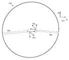
도 6a는 카메라 뷰 및 좌표 시스템의 예의 사시도를 도시하는 단순도이다.
도 6b는 센서 또는 디스플레이 및 관련된 좌표 시스템의 관점에서의 카메라 뷰를 도시하는 단순도이다.
도 7는 관절식 암의 하나 이상의 조인트로의 교란을 보상하면서 사용자 명령에 기초하여 관절식 암을 이동시키는 방법의 단순도이다.
도 8a 내지 도 8g는 여기에 기술된 일체 컴퓨터 지원 디바이스 및 가동 수술 테이블을 통합하는 다양한 컴퓨터 지원 디바이스 시스템을 도시하는 개략 단순도이다.
도면에서, 동일한 표시를 갖는 부재는 동일하거나 유사한 기능을 갖고 있다.1 is a simplified diagram of a computer assistance system in accordance with some embodiments.
2 is a simplified diagram illustrating a computer assistance system in accordance with some embodiments.
3 is a simplified diagram illustrating a kinematics model of a computer-aided medical system in accordance with some embodiments.
4 is a simplified diagram of a method of staggering the release of a brake for an articulated arm.
Figure 5 is a simplified diagram of a method for compensating for a disturbance from one joint set to an intersection with a second joint set.
6A is a simplified diagram showing a perspective view of an example of a camera view and coordinate system.
6B is a simplified diagram illustrating a camera view from the perspective of a sensor or display and associated coordinate system.
7 is a simplified diagram of a method for moving an articulated arm based on a user command while compensating for a disturbance to one or more joints of the articulated arm.
8A-8G are schematic simplified diagrams illustrating various computer-aided device systems incorporating integral computer-aided devices and movable surgical tables described herein.
In the drawings, members having the same marks have the same or similar functions.
다음의 설명에서, 본 발명과 일치하는 일부 실시예를 기술하는 특정 세부사항이 제시되어 있다. 그러나, 일부 실시예는 이러한 특정 세부사항의 일부 또는 모두 없이 실시될 수 있다는 것을 당업자는 이해할 것이다. 여기에 개시된 특정 실시예는 설명을 위한 것이고 제한을 위한 것이 아니다. 당업자는 다른 요소가 여기에 구체적으로 기술되지 않았지만, 본 발명의 범위 및 정신 안에 있다는 것을 이해할 수 있다. 또한, 불필요한 반복을 피하기 위해, 하나의 실시예와 연관되어 도시되고 기술된 하나 이상의 특징은 달리 특정되지 않거나 하나 이상의 특징이 실시예를 비기능적으로 한다면 다른 실시예에 통합될 수 있다. 용어 "포함하는"은 포하지만 제한되지 않는 것을 의미하고, 포함된 하나 이상의 개별적인 아이템의 각각은 달리 언급되지 않으면 옵션으로 생각해야 한다. 마찬가지로, 용어 "할 수 있다"는 아이템이 옵션이라는 것을 나타낸다.In the following description, specific details are set forth describing some embodiments consistent with the present invention. However, those skilled in the art will understand that some embodiments may be practiced without some or all of these specific details. The specific embodiments disclosed herein are illustrative and not limiting. Those skilled in the art can understand that other elements not specifically described herein are within the scope and spirit of the present invention. Also, to avoid unnecessary repetition, one or more features shown and described in connection with one embodiment may be incorporated into another embodiment if not otherwise specified or if one or more features render the embodiment non-functional. The term "comprising" means including but not limited to, and each of the one or more individual items included should be considered optional unless otherwise stated. Similarly, the term "may" indicates that the item is optional.
도 1은 일부 실시예에 따른 컴퓨터 지원 시스템(100)의 단순도이다. 도 1에 도시된 바와 같이, 컴퓨터 지원 시스템(100)은 하나 이상의 가동 또는 관절식 암(120)을 구비한 장치(110)를 포함하고 있다. 이러한 하나 이상의 관절식 암(120)의 각각은 하나 이상의 엔드 이펙터를 지원한다. 일부 예에서, 장치(110)는 컴퓨터 지원 수술 장치와 일치할 수 있다. 이러한 하나 이상의 관절식 암(120)은 각각 관절식 암(120)의 적어도 하나의 말단부에 장착되는 하나 이상의 기기, 수술 기기, 이미징 장치 및/또는 그밖에 유사한 것에 대한 지지를 제공한다. 일부 실시예에서, 장치(110) 및 오퍼레이터 워크스테이션은 캘리포니아, 서니베일의 인튜어티브 서지컬 인코퍼레이티드에 의해 판매되는 da Vinci®Surgical System에 상응할 수 있다. 일부 실시예에서, 다른 구성, 보다 적거나 많은 관절식 암, 및/또는 그밖의 유사한 것을 구비한 컴퓨터 지원 수술 장치가 옵션으로 컴퓨터 지원 시스템(100)과 함께 사용될 수 있다.1 is a simplified diagram of a
장치(110)는 인터페이스를 통해 제어 유닛(130)에 결합되어 있다. 이러한 인터페이스는 하나 이상의 무선 링크, 케이블, 커넥터, 및/또는 버스를 포함할 수 있고 하나 이상의 네트워크 스위칭 및/또는 라우팅 장치를 구비한 하나 이상의 네트워크를 더 포함할 수 있다. 제어 유닛(130)은 메모리(150)에 결합된 프로세서(140)를 포함하고 있다. 제어 유닛(130)의 동작은 프로세서(140)에 의해 제어된다. 제어 유닛(130)이 오직 하나의 프로세서(140)를 갖는 것으로 도시되어 있지만, 프로세서(140)는 제어 유닛(130) 내의 하나 이상의 중앙 처리 유닛, 멀티코어 프로세서, 마이크로프로세서, 마이크로컨트롤러, 디지털 신호 프로세서, 전계 프로그래머블 게이트 어레이(FPGA), 주문형 집적 회로(ASIC) 및/또는 그밖의 것을 나타낼 수 있다는 것을 이해해야 한다. 제어 유닛(130)은 컴퓨팅 장치에 더해진 독립형 서브시스템 및/또는 보드 또는 가상 머신으로서 구현될 수 있다. 일부 실시예에서, 제어 유닛은 오퍼레이터 워크스테이션의 일부로서 포함되고 및/또는 오퍼레이터 워크스테이션으로부터 떨어져 동작되지만 함께 동작될 수도 있다. 제어 유닛(130)과 같은 제어 유닛의 일부 예는 하나 이상의 프로세서(예를 들어, 프로세서(140))에 의해 실행될 때 이러한 하나 이상의 프로세서가 방법 400의 프로세스를 실행하도록 할 수 있는 실행가능한 코드를 포함하는 비임시, 유형, 기계 판독가능 매체를 포함할 수 있다.
메모리(150)는 제어 유닛(130)에 의해 실행되는 소프트웨어 및/또는 제어 유닛(130)의 동작 동안 사용되는 하나 이상의 데이터 구조를 저장하는데 사용된다. 메모리(150)는 하나 이상 타입의 기계 판독가능 매체를 포함할 수 있다. 일부 공통 형태의 기계 판독가능 매체는 플로피 디스크, 플렉시블 디스크, 하드 디스크, 자기 테이프, 임의의 다른 자기 매체, CD-ROM, 임의의 다른 광학 매체, 펀치 카드, 페이퍼 테이프, 구멍의 패턴을 갖는 임의의 다른 물리적 매체, RAM, PROM, EPROM, FLASH-EPROM, 임의의 다른 메모리 칩 또는 카트리지, 및/또는 프로세서 또는 컴퓨터가 판독하도록 구성된 임의의 다른 매체를 포함할 수 있다.Memory 150 is used to store software executed by control unit 130 and/or one or more data structures used during operation of control unit 130 . Memory 150 may include one or more types of machine readable media. Some common forms of machine readable media include floppy disks, flexible disks, hard disks, magnetic tape, any other magnetic media, CD-ROM, any other optical media, punch cards, paper tape, any with a pattern of holes. other physical media, RAM, PROM, EPROM, FLASH-EPROM, any other memory chip or cartridge, and/or any other media configured to be read by a processor or computer.
도시된 바와 같이, 메모리(150)는 장치(110)의 자율 및/또는 반자율 제어를 지원하는 모션 제어 애플리케이션(160)을 포함하고 있다. 모션 제어 애플리케이션(160)은 장치(110)로부터 위치, 모션, 및/또는 센서 정보를 수신하고, 수술 테이블 및/또는 이미징 장치와 같은 다른 장치에 대해 다른 제어 유닛과 위치, 모션, 및/또는 충돌 회피 정보를 교환하고, 및/또는 장치(110), 관절식 암(120), 및/또는 장치(110)의 엔드 이펙터에 대한 모션을 계획하고 및/또는 모션의 계획을 돕기 위한 하나 이상의 애플리케이션 프로그래밍 인터페이스(API)를 포함할 수 있다. 그리고 모션 제어 애플리케이션(160)이 소프트웨어 애플리케이션으로서 도시되어 있지만, 모션 제어 애플리케이션(160)은 하드웨어, 소프트웨어, 및/또는 하드웨어 및 소프트웨어의 조합을 사용하여 구현될 수 있다.As shown, memory 150 includes a motion control application 160 that supports autonomous and/or semi-autonomous control of
일부 실시예에서, 컴퓨터 지원 시스템(100)은 동작실 및/또는 조정실에서 발견될 수 있다. 그리고 컴퓨터 지원 시스템(100)이 2개의 관절식 암(120)을 갖는 오직 하나의 장치(110)를 포함하고 있지만, 컴퓨터 지원 시스템(100)은 장치(110)와 유사하고 및/또는 상이한 설계의 관절식 암 및/또는 엔드 이펙터를 갖는 임의의 수의 장치를 포함할 수 있다는 것을 당업자는 이해할 것이다. 일부 예에서, 이러한 장치의 각각은 보다 적거나 보다 많은 관절식 암 및/또는 엔드 이펙터를 포함할 수 있다.In some embodiments,
컴퓨터 지원 시스템(100)은 수술 테이블(170)을 더 포함한다. 하나 이상의 관절식 암(120)과 같이, 수술 테이블(170)은 수술 테이블(170)의 베이스와 상대적인 테이블 상부(180)의 관절식 이동을 지원한다. 일부 예에서, 테이블 상부(180)의 관절식 이동은 테이블 상부(180)의 높이, 틸트, 슬라이드, 트렌델렌부르크 방향등을 변경하기 위한 서포트를 포함할 수 있다. 도시되지는 않았지만, 수술 테이블(170)은 테이블 상부(180)의 위치 및/또는 방향을 제어하기 위한 수술 테이블 명령 유닛과 같은 하나 이상의 제어 입력부를 포함할 수 있다. 일부 실시예에서, 수술 테이블(170)은 독일의 Trumpf Medical Systems GmbH에 의해 판매되는 수술 테이블의 하나 이상에 상응할 수 있다.
수술 테이블(170)은 또한 상응하는 인터페이스를 통해 제어 유닛(130)에 결합되어 있다. 이러한 인터페이스는 하나 이상의 무선 링크, 케이블, 커넥터, 및/또는 버스를 포함할 수 있고, 하나 이상의 네트워크 스위칭 및/또는 라우팅 장치를 갖는 하나 이상의 네트워크를 더 포함할 수 있다. 일부 실시예에서, 수술 테이블(170)은 제어 유닛(130)과 상이한 제어 유닛에 결합될 수 있다. 일부 예에서, 모션 제어 애플리케이션(160)은 수술 테이블(170) 및/또는 테이블 상부(180)과 연관된 위치, 운동, 및/또는 다른 센서 정보를 수신하기 위한 하나 이상의 애플리케이션 프로그래밍 인터페이스(API)를 포함할 수 있다. 일부 예에서, 모션 제어 애플리케이션(160)은 관절식 암, 기기, 엔드 이펙터, 수술 테이블 구성요소 등의 이동, 조인트 및 링크의 운동 제한 범위를 피하여 관절식 암, 기기, 엔드 이펙터, 수술 테이블 구성요소등의 다른 운동을 보상하고, 내시경과 같은 뷰잉 장치를 조정하여 관심의 영역 및/또는 하나 이상의 기기 또는 엔드 이펙터를 뷰잉 장치의 시야 안에 유지 및/또는 배치하도록 구성된, 충돌 회피와 연관된 운동 계획에 기여할 수 있다. 일부 예에서, 모션 제어 애플리케이션(160)은 수술 테이블(170) 및/또는 수술 상부(180)에 대한 모션을 계획하고 및/또는 계획하는 것을 도울 수 있다. 일부 예에서, 모션 제어 애플리케이션(160)은 수술 테이블 명령 유닛을 사용함으로써 수술 테이블(170) 및/또는 테이블 상부(180)의 이동을 방지하는 것과 같이 하여 수술 테이블(170) 및/또는 테이블 상부(180)의 모션을 방지할 수 있다. 일부 예에서, 모션 제어 애플리케이션(160)은 레지스터 장치(110)와 수술 테이블(170) 사이의 기하학적 관계를 알도록 수술 테이블(170)과 함께 레지스터 장치(110)를 도울 수 있다. 일부 예에서, 기하학적 관계는 레지스터 장치(110) 및 수술 테이블(170)에 대해 유지되는 좌표 프레임들 사이에 병진 및/또는 하나 이상의 회전을 포함할 수 있다.The operating table 170 is also coupled to the control unit 130 via a corresponding interface. Such an interface may include one or more wireless links, cables, connectors, and/or buses, and may further include one or more networks having one or more network switching and/or routing devices. In some embodiments, operating table 170 may be coupled to a different control unit than control unit 130 . In some examples, motion control application 160 includes one or more application programming interfaces (APIs) for receiving position, motion, and/or other sensor information associated with surgical table 170 and/or
제어 유닛(130)은 또한 인터페이스를 통해 오퍼레이터 워크스테이션(190)에 결합될 수 있다. 오퍼레이터 워크스테이션(190)은 관절식 암(120) 및 엔드 이펙터의 이동 및/또는 운전을 제어하기 위해 의사와 같은 운전자에 의해 사용될 수 있다. 관절식 암(120) 및 엔드 이펙터의 운전을 지원하기 위해, 오퍼레이터 워크스테이션(190)은 관절식 암(120) 및/또는 엔드 이펙터중 하나 이상의 적어도 일부의 영상을 표시하기 위한 디스플레이 시스템(192)을 포함하고 있다. 예를 들어, 디스플레이 시스템(192)은 관절식 암(120) 및/또는 엔드 이펙터가 사용되고 있을 때 이들을 운전자가 보는 것이 비현실적이고 및/또는 불가능할 때 사용될 수 있다. 일부 실시예에서, 디스플레이 시스템(192)은 관절직 암(120)중 하나, 또는 제3 관절식 암(도시되지 않음)에 의해 제어되는, 내시경과 같은, 비디오 포착 장치로부터 비디오 영상을 표시한다.Control unit 130 may also be coupled to
오퍼레이터 워크스테이션(190)은 레지스터 장치(110), 관절식 암(120), 및/또는 이러한 관절식 암(120)에 장착된 엔드 이펙터를 운전하는데 사용될 수 있는 하나 이상의 입력 컨트롤(195) 또는 마스터 컨트롤(195)을 가진 콘솔 워크스테이션을 포함하고 있다. 이러한 입력 컨트롤(195)의 각각은 이들 자체의 관절식 암의 말단부에 결합되어 입력 컨트롤(195)의 이동은 오퍼레이터 워크스테이션(190)에 의해 검출되고 제어 유닛(130)에 통신된다. 향상된 인체공학을 제공하기 위해, 콘솔 워크스페이스는 또한 운전자가 입력 컨트롤(195)을 조작하는 동안 그들의 팔을 쉬게 할 수 있는 암 레스트(197)과 같은 하나 이상의 레스트를 포함할 수 있다. 일부 예에서, 디스플레이 시스템(192) 및 입력 컨트롤(195)은 관절식 암(120) 및/또는 이러한 관절식 암(120)에 장착된 엔드 이펙터를 원격조정하기 위해 운전자에 의해 사용될 수 있다. 일부 실시예에서, 장치(110), 오퍼레이터 워크스테이션(190), 및 제어 유닛(130)은 캘리포니아, 서니베일의 인튜어티브 서지컬 인코퍼레이티드에 의해 판매되는 da Vinci®Surgical System에 상응할 수 있다.
일부 실시예에서, 다른 구성 및/또는 구조가 컴퓨터 지원 시스템(100)과 함께 사용될 수 있다. 일부 예에서, 제어 유닛(130)은 오퍼레이터 워크스테이션(190) 및/또는 장치(110)의 일부로서 포함될 수 있다. 일부 실시예에서, 컴퓨터 지원 시스템(100)은 수술실 및/또는 중재실에서 발견될 수 있다. 컴퓨터 지원 시스템(100)이 2개의 관절식 암(120)을 갖는 오직 하나의 장치(110)를 포함하고 있지만, 당업자중 하나는 컴퓨터 지원 시스템(100)이 장치(110)와 유사하고 및/또는 상이한 설계의 관절식 암 및/또는 엔드 이펙터를 갖는 임의의 수의 장치를 포함할 수 있다는 것을 이해할 것이다. 일부 예에서, 이러한 장치의 각각은 보다 적거나 많은 관절식 암(120) 및/또는 엔드 이펙터를 포함할 수 있다. 추가로, 장치(110)에 부착될 수 있는 추가의 암을 제어하는 추가의 워크스테이션(190)이 존재할 수 있다. 또한, 일부 실시예에서, 워크스테이션(190)은 수술 테이블(170)을 제어하기 위한 컨트롤을 가질 수 있다.In some embodiments, other configurations and/or architectures may be used with
도 2는 일부 실시예에 따른 컴퓨터 지원 시스템(200)을 도시하는 단순도이다. 예를 들어, 컴퓨터 지원 시스템(200)은 컴퓨터 지원 시스템(100)과 일치할 수 있다. 도 2에 도시된 바와 같이, 컴퓨터 지원 시스템(200)은 하나 이상의 관절식 암을 갖는 컴퓨터 지원 장치(210) 및 수술 테이블(280)을 포함하고 있다. 도 2에는 도시되어 있지 않지만, 컴퓨터 지원 장치(210) 및 수술 테이블(280)은 하나 이상의 인터페이스 및 하나 이상의 제어 유닛을 사용하여 함께 결합되어 있어서, 적어도 수술 테이블(280)에 대한 운동학 정보가 컴퓨터 지원 장치(210)의 관절식 암의 모션을 실행하는데 사용되는 모션 제어 애플리케이션에 알려진다.2 is a simplified diagram illustrating a
컴퓨터 지원 장치(210)는 다양한 링크 및 조인트를 포함하고 있다. 도 2의 실시예에서, 컴퓨터 지원 장치는 일반적으로 3개의 상이한 세트의 링크 및 조인트로 분리된다. 먼저 모바일 카트(215) 또는 환자측 카트(215)의 인접 단부에 셋업 구조부(220)가 있다. 이러한 셋업 구조부의 말단부에는 관절식 암을 형성하는 일련의 링크 및 셋업 조인트(240)가 결합되어 있다. 그리고 이러한 셋업 조인트(240)의 말단부에는 다관절 매니퓰레이터(260)가 결합되어 있다. 일부 예에서, 일련의 셋업 조인트(240) 및 매니퓰레이터(260)는 관절식 암(120)중 하나에 대응할 수 있다. 그리고 컴퓨터 지원 장치가 오직 하나의 일련의 셋업 조인트(240) 및 상응하는 매니퓰레이터(260)를 갖는 것으로 도시되어 있지만, 당업자는 컴퓨터 지원 장치가 하나 보다 많은 일련의 셋업 조인트(240) 및 상응하는 매니퓰레이터(260)를 포함할 수 있어서 컴퓨터 지원 장치는 다수의 관절식 암을 장착할 수 있음을 이해할 것이다.Computer aided
도시된 바와 같이, 컴퓨터 지원 장치(210)는 이동 카트(215)에 장착되어 있다. 이러한 이동 카트(215)에 의해 컴퓨터 지원 장치(210)는 컴퓨터 지원 장치를 수술 테이블(280)에 근접하여 보다 더 잘 위치지정하도록 수술실 사이에서 또는 수술실 안에서와 같이 위치 이동될 수 있다. 셋업 구조부(220)는 이동 카트(215)에 장착되어 있다. 도 2에 도시된 바와 같이, 셋업 구조부(220)는 컬럼 링크(221, 222)를 포함하는 2파트 컬럼을 포함하고 있다. 컬럼 링크(222)의 상단부 또는 말단부에는 쇼울더 조인트(223)가 결합되어 있다. 쇼울더 조인트(223)에는 붐 링크(224, 225)를 포함하는 2-파트 붐이 결합되어 있다. 붐 링크(225)의 말단부에는 팔목 조인트(226)가 있고, 팔목 조인트(226)에는 암 장착 플랫폼(227)이 결합되어 있다.As shown, computer aided
셋업 구조부(220)의 링크 및 조인트는 암 장착 플랫폼(227)의 위치 및 방향(즉, 포즈)을 변경하기 위한 다양한 자유도를 포함하고 있다. 예를 들어, 2-파트 컬럼이 축(232)을 따라 쇼울더 조인트(223)를 이동시킴으로써 암 장착 플랫폼(227)의 높이를 조정하는데 사용될 수 있다. 이러한 암 장착 플랫폼(227)은 쇼울더 조인트(223)를 사용하여 이동 카트(215), 2-파트 컬럼, 및 축(232)에 대해 추가로 회전될 수 있다. 암 장착 플랫폼(227)의 수평 위치 역시 2-파트 붐을 사용하여 축(234)를 따라 조정될 수 있다. 그리고 암 장착 플랫폼(227)의 방향 역시 팔목 조인트(226)를 사용하여 암 장착 플랫폼 배향 축(236)에 대해 회전함으로써 조정될 수 있다. 따라서, 셋업 구조부(220)의 링크 및 조인트의 모션 리미트에 의해, 암 장착 플랫폼(227)의 위치는 2-파트 컬럼을 사용하여 이동 카트(215) 위로 수직으로 조정될 수 있다. 암 장착 플랫폼(227)의 위치 역시 각각 2-파트 붐 및 쇼울더 조인트(223)를 사용하여 이동 카트(215)에 대해 방사형으로 그리고 각지게 조정될 수 있다. 그리고 암 장착 플랫폼(227)의 각도 방향 역시 팔목 조인트(226)를 사용하여 변경될 수 있다.The links and joints of the
암 장착 플랫폼(227)은 하나 이상의 관절식 암을 위한 장착점으로서 사용될 수 있다. 이동 카트(215)에 대해 암 장착 플랫폼(227)의 높이, 수평 위치, 및 방향을 조정하는 기능은 수술 또는 시술이 시행되는 이동 카트(215) 근방에 위치된, 환자와 같은, 작업 공간에 대해 하나 이상의 관절식 암을 위치지정하고 배향하기 위한 유연한 셋업 구조부를 제공한다. 예를 들어, 암 장착 플랫폼(227)이 환자 위에 위치지정되어 다양한 관절식 암 및 이들의 상응하는 매니퓰레이터 및 기기가 환자에게 시술을 실행하기에 충분한 범위의 운동을 가질 수 있다. 도 2는 제1 셋업 또는 플렉스 조인트(242)를 사용하여 암 장착 플랫폼(227)에 결합된 단일 관절식 암을 도시하고 있다. 그리고, 오직 하나의 관절식 암이 도시되어 있지만, 당업자는 다수의 관절식 암이 추가 제1 셋업 조인트를 사용하여 암 장착 플랫폼(227)에 결합될 수 있음을 이해할 것이다.Arm mounting
제1 셋업 조인트(242)는 환자측 카트(215)에 최근접한 관절식 암의 셋업 조인트(240) 섹션을 형성한다. 셋업 조인트(240)는 일련의 조인트 및 링크를 더 포함할 수 있다. 도 2에 도시된 바와 같이, 셋업 조인트(240)는 (뚜렷이 도시되지 않은) 하나 이상의 조인트를 통해 결합된 링크(244, 246)를 포함할 수 있다. 셋업 조인트(240)의 조인트 및 링크는 제1 셋업 조인트(242)를 사용하여 축(252)에 대해 암 장착 플랫폼(227)에 상대적으로 셋업 조인트(240)를 회전시키고, 제1 셋업 조인트(242)와 링크(246) 사이의 방사형 또는 수평 거리를 조정하고, 축(254)을 따라 배향 플랫폼에 상대적으로 링크(246)의 말단부에서 매니퓰레이터 마운트(262)의 높이를 조정하고, 매니퓰레이터 마운트(262)를 축(254)에 대해 회전시키는 기능을 포함하고 있다. 일부 예에서, 셋업 조인트(240)는 암 장착 플랫폼(227)에 상대적으로 매니퓰레이터 마운트(262)의 포즈를 변경하기 위한 추가 자유도를 허용하는 추가적인 조인트, 링크 및 축을 더 포함할 수 있다.The first setup joint 242 forms the section of the
매니퓰레이터(260)는 매니퓰레이터 마운트(262)를 통해 셋업 조인트(240)의 말단부에 결합되어 있다. 매니퓰레이터(260)는 매니퓰레이터(260)의 말단부에 장착된 기기 캐리지(268)와 함께 추가 조인트(264) 및 링크(266)를 포함하고 있다. 기기(270)가 기기 캐리지(268)에 장착되어 있다. 이러한 기기(270)는 삽입축을 따라 정렬된 샤프트(272)를 포함하고 있다. 샤프트(272)는 보통 원격 운동 중심(274)를 통해 통과되도록 정렬되어 있다. 운동의 원격 운동 중심(274)의 위치는 보통 매니퓰레이터 마운트(262)에 대해 고정 병진 관계로 유지되어서 매니퓰레이터(260)의 조인트(264)의 동작에 의해 운동의 원격 운동 중심(274)에 대해 샤프트(272)가 회전한다. 이러한 실시예에 따라, 매니퓰레이터 마운트(262)에 대한 운동의 원격 운동 중심(274)의 고정 병진 관계는 매니퓰레이터(262)의 조인트(264) 및 링크(266)의 물리적 제약을 사용하여, 조인트(264)에 대해 허용된 운동에 대한 소프트웨어 제약을 사용하여, 및/또는 이 둘의 조합에 의해 유지된다. 조인트 및 링크의 물리적 제약을 사용하여 조작되는 원격 운동 중심을 사용하는 컴퓨터 지원 수술 장치의 대표적인 예가 2013년 5월 13일에 출원된, "Redundant Axis and Degree of Freedom for Hardware-Constrained Remote Center Robotic Manipulator" 표제의 미국 특허 출원 번호 13/906,888에 기술되어 있고, 소프트웨어 제약에 의해 조작되는 운동의 원격 센서를 사용하여 컴퓨터 지원 수술 장치의 대표적인 실시예가 2005년 5월 10일에 출원된, "Software Center and Highly Configurable Robotic Systems for Surgery and Other Uses" 표제의 미국 특허 번호 8,004,229에 기술되어 있고, 이들의 내용은 그 전체가 여기에 언급되어 통합되어 있다. 일부 예에서, 원격 운동 중심(274)은 환자(278)의, 절개 사이트 또는 구멍과 같은, 신체 개구의 위치에 상응할 수 있다. 원격 운동 중심(274)이 수술 포트에 상응하기 때문에, 기기(270)가 사용될 때에, 원격 운동 중심(274)은 환자(278)에 대해 고정된 상태가 되어 운동의 원격 운동 중심(274)에서 환자(278)의 인체에 대한 스트레스를 제한한다. 일부 예에서, 샤프트(272)는 수술 포트에 위치된 캐뉼라(도시되지 않음)를 통과할 수 있다. 일부 예에서, 비교적 더 큰 샤프트 또는 가이드 튜브 외경(예를 들어, 4-5 mm 이상)를 갖는 기기는 캐뉼라를 사용하여 신체 개구를 통과할 수 있고, 이러한 캐뉼라는 비교적 더 작은 샤프트 또는 가이트 튜브 외경(예를 들어, 2-3 mm 이하)을 갖는 기기에 옵션으로 생략될 수 있다.
샤프트(272)의 말단부에 엔드 이펙터(276)가 있다. 조인트(264) 및 링크(266)으로 인한 매니퓰레이터(260)의 자유도에 의해 적어도 매니퓰레이터 마운트(262)에 대해 샤프트(272) 및/또는 엔드 이펙터(276)의 롤, 피치, 및 요를 제어할 수 있다. 일부 예에서, 매니퓰레이터(260)의 자유도는 기기 캐리지(268)를 사용하여 샤프트(272)를 전진 및/또는 후퇴시키는 기능을 더 포함하여 엔드 이펙터(276)는 삽입축을 따라 그리고 운동의 원격 운동 중심(274)에 상대적으로 전진 및/또는 후퇴될 수 있다. 일부 예에서, 매니퓰레이터(260)는 캘리포니아, 서니베일의 인튜어티브 서지컬 인코퍼레이티드에 판매되는 da Vinci®Surgical System와 함께 사용하기 위한 매니퓰레이터와 일치할 수 있다. 일부 예에서, 기기(270)는 내시경과 같은 이미징 장치, 그립퍼, 소작 또는 메스와 같은 수술 기기 등일 수 있다. 일부 예에서, 엔드 이펙터(276)는 샤프트(272)의 말단부에 대해 엔드 이펙터(276)의 일부의 추가 국부적인 조작을 가능하게 하는 롤, 피치, 요소, 그립 등과 같은 추가 자유도를 포함할 수 있다.At the distal end of
수술 또는 다른 의료 시술 동안, 환자(278)는 보통 수술 테이블(280) 위에 위치되어 있다. 수술 테이블(280)은 테이블 베이스(282)가 이동 카트(215)에 근접하여 위치된 상태로 테이블 베이스(282) 및 테이블 상부(284)를 포함하여 기기(270) 및/또는 엔드 이펙터(276)는 기기(270)의 샤프트(272)가 환자(278)의 신체 개구에 삽입되어 있는 동안 컴퓨터 지원 장치(210)에 의해 조작될 수 있다. 수술 테이블(280)은 테이블 베이스(282)와 테이블 상부(284) 사이에 하나 이상의 조인트 또는 링크를 포함하는 관절식 구조부(290)를 더 포함하여, 테이블 베이스(282)에 대한, 테이블 상부(284), 그래서 환자(278)의 상대 위치가 제어될 수 있다. 일부 예에서, 관절식 구조부(290)는 테이블 상부(284) 위의 포인트에 위치될 수 있는 가상 규정된 테이블 운동 이소(iso) 센터(286)에 상대적으로 테이블 상부(284)가 제어되도록 구성될 수 있다. 일부 예에서, 이소센터(286)는 환자(278)의 내부에 위치될 수 있다. 일부 예에서, 이소센터(286)는 원격 운동 중심(274)에 상응하는 신체 개구 사이트와 같은, 신체 개구중 하나에 또는 근방에 환자의 인체 벽과 연어될 수 있다.During surgery or other medical procedures,
도 2에 도시된 바와 같이, 관절식 구조부(290)는 테이블 상부(824)가 테이블 베이스(282)에 상대적으로 상승 및/또는 하강될 수 있도록 높이 조정 조인트(292)를 포함하고 있다. 관절식 구조부(290)는 이소센터(286)에 대해 테이블 상부(284)의 틸트(296) 및 트렌델렌부르크(296) 방향 모두를 변경하기 위해 조인트 및 링크를 더 포함하고 있다. 이러한 틸트(294)에 의해 테이블 상부(284)가 좌우로 기울어질 수 있어서 환자(278)의 좌측 또는 우측이 환자(278)의 타측에 대해 상방으로 (즉, 테이블 상부(284)의 종방향으로 또는 상하축에 대해) 회전될 수 있다. 트렌델렌부르크(296)에 의해 테이블 상부(284)는 회전되어 환자(278)의 발이 상승되거나(트렌델렌부르크) 환자(278)의 머리가 상승된다(역 트렌델렌부르크). 일부 예에서, 틸트(294) 및/또는 트렌델렌부르크(296) 회전은 이소센터(286)에 대한 회전을 발생시키도록 조정될 수 있다. 관절식 구조부(290)는 도 2에 도시된 바와 같이 대략 좌측 및/또는 우측 운동으로 테이블 상부(284)가 테이블 베이스(282)에 대해 종방향(머리-꼬리) 축을 따라 미끄러지도록 추가 링크 및 조인트(298)를 더 포함하고 있다.As shown in FIG. 2 , articulating
도 8a 내지 도 8g는 여기에 기술된 통합 컴퓨터 지원 장치 및 가동 수술 테이블 특징부를 포함하는 다양한 컴퓨터 지원 장치 시스템 구조를 도시하는 단순 개략도이다. 이러한 다양한 도시된 시스템 구성요소는 여기에 기술된 원리에 따르고 있다. 이러한 도면에서, 구성요소는 이해를 위해 단순화되어 있고, 개별적인 링크, 조인트, 매니퓰레이터, 기기, 엔드 이펙터 등과 같은 다양한 세부요소는 도시되어 있지 않지만, 이들은 다양한 구성요소에 포함되어 있는 것으로 이해해야 한다.8A-8G are simplified schematic diagrams illustrating various computer-aided device system structures including integrated computer-aided device and movable surgical table features described herein. These various illustrated system components conform to the principles described herein. In these drawings, components are simplified for understanding, and various details such as individual links, joints, manipulators, instruments, end effectors, etc. are not shown, but it should be understood that they are included in the various components.
이러한 구조에서, 하나 이상의 수술 기기 또는 기기의 클러스터와 연관된 캐뉼라는 도시되어 있지 않고, 캐뉼라 및 다른 기기 가이드 장치가 비교적 더 큰 샤프트 또는 가이드 튜브 외경(예를 들어, 4-5 mm 이상)을 갖는 기기 또는 기기 클러스터에 옵션으로 사용될 수 있고 비교적 더 작은 샤프트 또는 가이드 튜브 외경(예를 들어, 2-3 mm 이하)을 갖는 기기에 대해 옵션으로 생략될 수 있다는 것을 이해해야 한다.In this configuration, cannulas associated with one or more surgical instruments or clusters of instruments are not shown, and the cannulas and other instrument guide devices have relatively larger shaft or guide tube outer diameters (eg, 4-5 mm or more). Or it can be used as an option for instrument clusters and can be optionally omitted for instruments with relatively smaller shaft or guide tube outer diameters (eg, 2-3 mm or less).
또한, 이러한 구조에서, 원격조정 매니퓰레이터는 수술 동안 하드웨어 제약(예를 들어, 고정 교차 기기 피치, 요, 및 롤 축) 또는 소프트웨어 제약(예를 들어, 소프트웨어 제약된 교차 기기 피치, 요, 롤 축)을 사용함으로써 원격 운동 중심을 규정하는 매니퓰레이터를 포함하는 것으로 이해해야 한다. 이러한 기기 회전축의 하이브리드가 규정되는 것(예를 들어, 하드웨어 제약된 롤 축 및 소프트웨어 제약된 피치 및 요 축) 역시 가능하다. 또한, 일부 매니퓰레이터 시술 동안 어떤 회전의 수술 기기 축도 규정하고 제약할 수 없고, 일부 매니퓰레이터는 시술 동안 오직 하나 이상의 회전의 기기 축을 규정하고 제약할 수 있다.Also, in this configuration, the telecontrol manipulator may be subject to hardware constraints (eg, fixed cross-machine pitch, yaw, and roll axes) or software constraints (eg, software-constrained cross-machine pitch, yaw, and roll axes) during surgery. It should be understood to include a manipulator defining a remote center of motion by using . It is also possible for hybrids of these machine rotational axes to be defined (eg, a hardware constrained roll axis and a software constrained pitch and yaw axis). Additionally, some manipulators cannot define and constrain any surgical instrument axis of rotation during a procedure, and some manipulators can only define and constrain one or more instrument axes of rotation during a procedure.
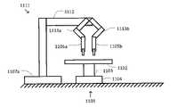
도 8a는 가동 수술 테이블(1100) 및 단일 기기 컴퓨터 지원 장치(1101a)를 도시하고 있다. 수술 테이블(1100)은 가동 테이블 상부(1102) 및 말단부에서 테이블 상부(1102)를 지지하기 위해 기계적으로 접지된 테이블 베이스(1104)로부터 뻗은 테이블 지지 구조부(1103)를 포함하고 있다. 일부 예에서, 수술 테이블(1100)은 수술 테이블(170 및/또는 280)과 일치할 수 있다. 컴퓨터 지원 장치(1101a)는 원격조정 매니퓰레이터 및 단일 기기 어셈블리(1105a)를 포함하고 있다. 컴퓨터 지원 장치(1101a)는 또한 근접 베이스(1107a)에서 기계적으로 접지되어 있고 말단부에서 매니퓰레이터 및 기기 어셈블리(1105a)를 지지하도록 뻗은 지지 구조부(1106a)를 포함하고 있다. 지지 구조부(1106a)는 어셈블리(1105a)가 수술 테이블(1100)에 대해 이동되고 다양한 고정 자세로 유지될 수 있도록 구성되어 있다. 베이스(1107a)는 옵션으로 수술 테이블(1100)에 대해 영구 고정되거나 이동가능하다. 수술 테이블(1100) 및 컴퓨터 지원 장치(1101a)는 여기에 기술된 바와 같이 함께 작동한다.8A shows a movable surgical table 1100 and a single unit computer assisted
도 8a는 또한 상응하는 지지 구조부(1106b)에 의해 지지되는 상응하는 개별적인 원격조정 매니퓰레이터 및 단일-기기 어셈블리(1105b)를 갖는, 2, 3, 4, 5개 이상의 개별적인 컴퓨터 지원 장치가 포함될 수 있다는 것을 도시한 옵션의 제2 컴퓨터 지원 장치(1101b)를 도시하고 있다. 컴퓨터 지원 장치(1101b)는 기계적으로 접지되어 있고, 어셈블리(1105b)는 컴퓨터 지원 장치(110a)와 유사한 포즈를 갖고 있다. 수술 테이블(1100) 및 컴퓨터 지원 장치(1101a, 1101b)는 함께 멀티-기기 수술 시스템을 만들고, 이들은 여기에 기술된 대로 함께 작동한다. 일부 예에서, 컴퓨터 지원 장치(110a 및/또는 1101b)는 컴퓨터 지원 장치(110 및/또는 210)와 일치할 수 있다.FIG. 8A also shows that two, three, four, five or more individual computer aided devices may be included, with corresponding individual remote manipulators and single-
도 8b에 도시된 바와 같이, 다른 가동 수술 테이블(1100) 및 컴퓨터 지원 장치(1111)가 도시되어 있다. 컴퓨터 지원 장치(1111)는 대표적인 매니퓰레이터 및 기기 어셈블리(1105a, 1105b)에 의해 도시된 바와 같이, 2, 3, 4, 5개 이상의 개별적인 원격조정 매니퓰레이터 및 단일-기기 어셈블리를 포함하는 멀티-기기 장치이다. 컴퓨터 지원 장치(1111)의 어셈블리(1105a, 1105b)는 결합 지지 구조부(1112)에 의해 지지되어, 어셈블리(1105a, 1105b)는 수술 테이블(1100)에 대해 그룹으로서 함께 이동되고 포즈를 가질 수 있다. 컴퓨터 지원 장치(1111)의 어셈블리(1105a, 1105b)는 또한 상응하는 개별적인 지지 구조부(1113a, 1113b)에 의해 각각 지지되어, 각각의 어셈블리(1105a, 1105b)는 수술 테이블(1100) 및 하나 이상의 다른 어셈블리(1105a, 1105b)에 대해 개별적으로 이동되고 포즈를 가질 수 있다. 각각의 멀티-기기 수술 시스템 구조부의 예는 인튜어티브 서지컬 인코퍼레이티드에 의해 판매되는, da Vinci Si® Surgical System 및 da Vinci® Xi™ Surgical System이다. 수술 테이블(1100) 및 예시적인 컴퓨터 지원 장치(1111)를 포함하는 수술 매니퓰레이터 시스템은 여기에 기술된 바와 같이 함께 작동한다. 일부 예에서, 컴퓨터 지원 장치(1111)는 컴퓨터 지원 장치(110 및/또는 210)와 일치한다.As shown in FIG. 8B , another movable surgical table 1100 and computer assisted
도 8a 및 도 8b의 컴퓨터 지원 장치는 각각 플로어에 기계적으로 접지되어 도시되어 있다. 그러나, 이러한 하나 이상의 컴퓨터 지원 장치는 옵션으로 벽 또는 천장에 기계적으로 접지될 수 있고 이러한 벽 또는 천장에 대해 영구 고정되거나 이동가능할 수 있다. 일부 예에서, 컴퓨터 지원 장치는 컴퓨터 지원 시스템의 지지 베이스가 수술 테이블에 대해 이동될 수 있도록 하는 트랙 또는 격자 시스템을 사용하여 벽 또는 천장에 장착될 수 있다. 일부 예에서, 하나 이상의 고정되거나 해제가능한 장착 클램프는 각각의 지지 베이스를 이러한 트랙 또는 격자 시스템에 장착하는데 사용될 수 있다. 도 8c에 도시된 바와 같이, 컴퓨터 지원 장치(1121a)는 벽에 기계적으로 접지되고, 컴퓨터 지원 장치(1121b)는 천장에 기계적으로 접지되어 있다.The computer aided device of FIGS. 8A and 8B is each shown mechanically grounded to the floor. However, such one or more computer aided devices may optionally be mechanically grounded to a wall or ceiling and may be permanently fixed or movable relative to such wall or ceiling. In some examples, the computer-assisted device may be wall or ceiling mounted using a track or grid system that allows the computer-assisted system's support base to be moved relative to the surgical table. In some examples, one or more fixed or releasable mounting clamps may be used to mount each support base to such a track or grid system. As shown in FIG. 8C, the
추가로, 컴퓨터 지원 장치는 가동 수술 테이블(1100)을 통해 간접적으로 기계적으로 접지될 수 있다. 도 8d에 도시된 바와 같이, 컴퓨터 지원 장치(1131a)는 수술 테이블(1100)의 테이블 상부(1102)에 결합되어 있다. 컴퓨터 지원 장치(1131a)는 도 8d에 점선 구조부로 도시한 바와 같이, 테이블 지지 구조부(1103) 또는 테이블 베이스(1104)와 같은, 수술 테이블(1100)의 다른 부분에 옵션으로 결합될 수 있다. 테이블 상부(1102)가 테이블 지지 구조부(1103) 또는 테이블 베이스(1104)에 대해 이동할 때, 컴퓨터 지원 장치(1131)는 마찬가지로 테이블 지지 구조부(1103) 또는 테이블 베이스(1104)에 대해 이동한다. 그러나, 컴퓨터 지원 장치(1131a)가 테이블 지지 구조부(1103) 또는 테이블 베이스(1104)에 결합될 때, 컴퓨터 지원 장치(1131a)의 베이스는 테이블 상부(1102)가 이동할 때 그라운드에 대해 고정된 상태로 있게 된다. 테이블 운동이 발생함에 따라, 환자에게 기기가 삽입되는 신체 개구 역시 이동할 수 있는데, 그 이유는 환자의 신체가 이동하고 테이블 상부(1102)에 대해 신체 위치를 변경할 수 있기 때문이다. 따라서, 컴퓨터 지원 장치(1131a)가 테이블 상부(1102)에 결합되는 실시예에 있어서, 테이블 상부(1102)는 로컬 기계 그라운드로서 기능하고, 신체 개구는 테이블 상부(1102)에 대해 이동하고, 컴퓨터 지원 장치(1131a)에 대해서도 이동한다. 도 8d는 또한 멀티-기기 시스템을 생성하기 위해 컴퓨터 지원 장치(1131a)와 마찬가지로 구성된, 제2 컴퓨터 지원 장치(1131b)가 옵션으로 추가될 수 있다는 것을 보여주고 있다. 이러한 수술 테이블에 결합된 하나 이상의 컴퓨터 지원 장치를 포함하는 시스템은 여기에 개시된 바와 같이 작동한다.Additionally, computer aided devices may be mechanically grounded indirectly through the movable surgical table 1100. As shown in FIG. 8D , computer aided
일부 실시예에서, 동일하거나 하이브리드 기계적 접지를 갖는 컴퓨터 지원 장치의 다른 조합이 가능하다. 예를 들어, 플로어에 기계적으로 접지된 하나의 컴퓨터 지원 장치 및, 수술 테이블을 통해 이러한 플로어에 기계적으로 접지된 제2 컴퓨터 지원 장치를 포함할 수 있다. 이러한 하이브리드 기계적 접지 시스템은 여기에 개시된 바와 같이 작동한다.In some embodiments, other combinations of computer aided devices with the same or hybrid mechanical grounding are possible. For example, one computer aided device mechanically grounded to the floor and a second computer aided device mechanically grounded to the floor via the operating table. This hybrid mechanical grounding system works as disclosed herein.
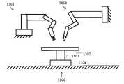
본 특징은 또한 2개 이상의 수술 기기가 단일 신체 개구를 통해 신체에 들어가는 단일-신체 개구 시스템을 포함하고 있다. 이러한 시스템의 예는 여기에 언급되어 통합된, 2010년 8월 12일에 출원된, "Surgical System Instrument Mounting" 표제의 미국 특허 번호 8,852,208 및, 2007년 6월 13일에 출원된 "Minimally Invasive Surgical System" 표제의 미국 특허 번호 9,060,678에서 볼 수 있다. 도 8e는 상술된 바와 같이 수술 테이블(1100)과 함께 원격조정 멀티-기기 컴퓨터 지원 장치(1141)를 도시하고 있다. 2개 이상의 기기(1142)는 각각 상응하는 매니퓰레이터(1143)에 결합되어 있고 기기(1142) 및 기기 매니퓰레이터(1143)의 클러스터는 시스템 매니퓰레이터(1145)에 의해 함께 이동한다. 이러한 시스템 매니퓰레이터(1144)는 시스템 매니퓰레이터(1144)가 이동되고 다양한 포즈에서 고정될 수 있도록 하는 지지 어셈블리(1145)에 의해 지지된다. 지지 어셈블리(1145)는 상기 설명과 일치하는 베이스(1146)에 기계적으로 접지되어 있다. 2개 이상의 기기(1142)는 단일 신체 개구에서 환자에게 삽입된다. 옵션으로, 기기(1142)는 단일 가이드 튜브를 통해 함께 뻗고, 가이드 튜브는 옵션으로, 상술된 문헌에서 기술된 바와 같이, 캐뉼라를 통해 뻗어 있다. 컴퓨터 지원 장치(1141) 및 수술 테이블(1100)은 여기에 기술된 바와 같이 함께 작동한다.This feature also includes single-body aperture systems where two or more surgical instruments enter the body through a single body aperture. Examples of such systems are US Patent No. 8,852,208, filed August 12, 2010, entitled "Surgical System Instrument Mounting," and filed June 13, 2007, incorporated herein by reference, and "Minimally Invasive Surgical System See U.S. Patent No. 9,060,678 entitled ". FIG. 8E shows a teleoperated multi-unit computer aided
도 8f는 옵션으로 테이블 상부(1102), 테이블 지지 구조부(1103), 또는 테이블 베이스(1104)에 결합되어, 수술 테이블(1100)을 통해 기계적으로 접지된 다른 멀티-기기, 단일 신체 개구 컴퓨터 지원 장치(1151)를 도시하고 있다. 도 8d에 대한 상기 설명 역시 도 8f에 도시된 기계적 접지 옵션에 적용된다. 컴퓨터 지원 장치(1151) 및 수술 테이블(1100)은 여기에 기술된 바와 같이 함께 작동한다.8F is another multi-instrument, single body aperture computer assisted device mechanically grounded via the operating table 1100, optionally coupled to the
도 8g는 하나 이상의 원격조정 멀티-기기, 단일 신체 개구 컴퓨터 지원 장치(1161) 및 하나 이상의 원격조정 단일-기기 컴퓨터 지원 장치(1162)가 여기에 기술된 바와 같이 수술 테이블(1100)과 함께 작동하도록 결합될 수 있음을 도시하고 있다. 컴퓨터 지원 장치(1161, 1162)의 각각은 직접 또는 다른 구조부를 통해, 여기에 기술된 다양한 방식으로 기계적으로 접지될 수 있다.FIG. 8G shows one or more remotely controlled multi-instrument, single body aperture computer aided
도 3은 일부 실시예에 따른 컴퓨터 지원 의료 시스템의 운동학 모델(300)의 단순도이다. 도 3에 도시된 바와 같이, 운동학 모델(300)은 많은 소스 및/또는 장치와 연관된 운동학 정보를 포함할 수 있다. 이러한 운동학 정보는 컴퓨터 지원 의료 장치 및 수술 테이블의 링크 및 조인트에 대한 공지된 운동학 모델에 기초한다. 이러한 운동학 정보는 또한 컴퓨터 지원 의료 장치 및 수술 테이블의 조인트의 위치 및/또는 방향과 연관된 정보에 기초한다. 일부 예에서, 이러한 조인트의 위치 및/또는 방향과 연관된 정보는 프리즘 조인트의 선형 위치 및 회전 조인트의 회전 위치를 측정하는, 인코더와 같은, 하나 이상의 센서로부터 유도될 수 있다.3 is a simplified diagram of a
이러한 운동학 모델(300)은 다수의 좌표 프레임 또는 좌표계 및, 좌표 프레임의 하나로부터 좌표 프레임의 다른 것으로 위치 및/또는 방향을 변환하기 위한 동종 변환과 같은 변환을 포함하고 있다. 일부 예에서, 운동학 모델(300)은 도 3에 포함된 변환 링크에 의해 표시된 순방향 및/또는 반전/역방향 변환을 구성함으로써 좌표 프레임중 임의의 다른 것에서 좌표 프레임중 하나의 위치 및/또는 방향의 순방향 및/또는 역방향 맵핑을 허용하도록 사용될 수 있다. 일부 예에서, 변환이 행렬 형태로 동종 변환으로서 모델화될 때, 이러한 구성은 행렬 승산을 사용하여 달성될 수 있다. 일부 실시예에서, 시스템은 좌표 기준 프레임을 이러한 운동학 체인의 하나 이상의 포인트에 부착하고 운동학 모델(300)의 하나의 기준 프레임으로부터 다른 프레임으로 변환하기 위해 Denavit-Hartenberg 파라미터 및 컨벤션을 사용할 수 있다. 일부 실시예에서, 운동학 모델(300)은 도 2의 컴퓨터 지원 장치(210) 및 수술 테이블(280)의 운동학 관계를 모델화하는데 사용될 수 있다.This
운동학 모델(300)은 수술 테이블(170) 및/또는 수술 테이블(280)과 같은, 수술 테이블의 위치 및/또는 방향을 모델화하는데 사용되는 테이블 베이스 좌표 프레임(305)을 포함하고 있다. 일부 예에서, 이러한 테이블 베이스 좌표 프레임(305)은 수술 테이블과 연관된 기준점 및/또는 방향에 대한 수술 테이블의 다른 점을 모델화하는데 사용될 수 있다. 일부 예에서, 이러한 기준점 및/또는 방향은 테이블 베이스(282)와 같은, 수술 테이블의 테이블 베이스와 연관될 수 있다. 일부 예에서, 테이블 베이스 좌표 프레임(305)은 컴퓨터 지원 시스템을 위한 글로벌 좌표 프레임으로서 사용되기에 적합할 수 있다.
운동학 모델(300)은 테이블 상부(284)와 같은, 수술 테이블의 테이블 상부를 나타내는 좌표 프레임에서의 위치 및/또는 방향을 모델화하는데 사용될 수 있는 테이블 상부 좌표 프레임(310)을 더 포함하고 있다. 일부 예에서, 테이블 상부 좌표 프레임(310)은 회전 센터 또는 이소센터(286)와 같은, 테이블 상부의 이소 센터에 센터링될 수 있다. 일부 예에서, 테이블 상부 좌표 프레임(310)의 z축은 수술 테이블이 놓인 표면 또는 플로어에 대해 수직으로 및/또는 테이블 상부의 표면에 직교하는 방향을 가질 수 있다. 일부 예에서, 테이블 상부 좌표 프레임(310)의 x축과 y축은 테이블 상부의 종방향(상하) 및 측방향(좌우) 주축을 포착하도록 배향될 수 있다. 일부 예에서, 테이블 베이스-테이블 상부 좌표 변환(315)은 테이블 상부 좌표 프레임(310)과 테이블 베이스 좌표 프레임(305) 상의 위치 및/또는 방향을 맵핑하는데 사용될 수 있다. 일부 예에서, 관절식 구조부(290)와 같은, 수술 테이블의 관절식 구조부의 하나 이상의 운동학 모델은 과거 및/또는 현재 조인트 센서 판독값과 함께 테이블 베이스-테이블 상부 좌표 변환(315)을 결정하는데 사용된다. 일부 예에서, 도 2의 실시예와 일치하여, 테이블 베이스-테이블 상부 좌표 변환(315)이 수술 테이블과 연관된 높이, 틸트, 트렌델렌부르크, 및/또는 슬라이드 세팅의 합성 효과를 모델화한다.
운동학 모델(300)은 컴퓨터 지원 장치(110) 및/또는 컴퓨터 지원 장치(210)와 같은 컴퓨터 지원 장치의 위치 및/또는 방향을 모델화하는데 사용될 수 있는 장치 베이스 좌표 프레임을 더 포함하고 있다. 일부 예에서, 장치 베이스 좌표 프레임(320)은 컴퓨터 지원 장치와 연관된 기준점 및/또는 방향에 대해 컴퓨터 지원 장치의 다른 포인트를 모델화하는데 사용될 수 있다. 일부 예에서, 이러한 기준점 및/또는 방향은 이동 카트(215)와 같은, 컴퓨터 지원 장치의 장치 베이스와 연관될 수 있다. 일부 예에서, 장치 베이스 좌표 프레임(320)은 컴퓨터 지원 시스템에 대한 글로벌 좌표 프레임으로서 사용되기에 적합할 수 있다.
수술 테이블과 컴퓨터 지원 장치 사이의 위치 및/또는 방향 관계를 추적하기 위해, 수술 테이블과 컴퓨터 지원 장치 사이에 등록을 실행하는 것이 바람직하다. 도 3에 도시된 바와 같이, 이러한 등록은 테이블 상부 좌표 프레임(310)과 장치 베이스 좌표 프레임(320) 사이에서 등록 변환(325)을 결정하는데 사용될 수 있다. 일부 실시예에서, 등록 변환(325)은 테이블 상부 좌표 프레임(310)과 장치 베이스 좌표 프레임 사이의 일부 또는 전체 변환일 수 있다. 이러한 등록 변환(325)은 수술 테이블과 컴퓨터 지원 장치 사이의 구조적 배열에 기초하여 결정된다.In order to track the positional and/or directional relationship between the operating table and the computer-aided device, it is desirable to perform registration between the operating table and the computer-aided device. As shown in FIG. 3 , this registration can be used to determine a
컴퓨터 지원 장치가 테이블 상부(1102)에 장착된 도 8d 및 도 8f의 예에서, 등록 변환(325)은 테이블 베이스-테이블 상부 좌표 변환(315)으로 결정되고 컴퓨터 지원 장치가 테이블 상부(112)에 어디에 장착되는지를 안다.In the example of FIGS. 8D and 8F where the computer aided device is mounted to the
이러한 컴퓨터 지원 장치가 플로어에 배치되거나 벽 또는 천장에 장착되는 도 8a 내지 도 8c, 도 8e 및 도 8f의 예에서, 등록 변환(325)의 결정은 장치 베이스 좌표 프레임(320) 및 테이블 베이스 좌표 프레임(305)을 일부 제한함으로써 단순화된다. 일부 예에서, 이러한 제한은 장치 베이스 좌표 프레임(320) 및 테이블 베이스 좌표 프레임(305)이 동일한 수직상향 또는 z축에 일치하는 것을 포함한다. 수술 테이블이 바닥에 위치되었고 (예를 들어, 바닥에 수직인) 방의 벽 및 (예를 들어, 바닥에 평행한) 천장의 상대 방향이 알려져 있다는 가정하에, 공통 수직상향 또는 z 축(또는 적절한 방향 변환)이 장치 베이스 좌표 프레임(320) 및 테이블 베이스 좌표 프레임(305) 모두 또는 적절한 방향 변환에 대해 유지되는 것이 가능하다. 일부 예에서, 공통 z 축 때문에, 등록 변환(325)은 테이블 베이스 좌표 프레임(305)의 z축에 대한 장치 베이스-테이블 상부의 회전 관계 만을 모델화할 수 있다(예를 들어, θz 등록). 일부 예에서, 등록 변환(325)은 또한 테이블 베이스 좌표 프레임(305)과 장치 베이스 좌표 프레임(320) 사이의 수평 오프셋을 모델화할 수 있다(예를 들어, XY 등록). 이것은 컴퓨터 지원 장치 및 수술 테이블 사이의 수직(z) 관계가 알려져 있기 때문에 가능하다. 따라서, 테이블 베이스-테이블 상부 변환(315)의 테이블 상부의 높이의 변화는 장치 베이스 좌표 프레임(320)의 수직 조정과 유사한데, 그 이유는 테이블 베이스 좌표 프레임(305) 및 장치 베이스 좌표 프레임(320)의 수직축이 동일하거나 거의 동일하여서 테이블 베이스 좌표 프레임(305)과 장치 베이스 좌표 프레임(320) 사이의 높이의 변화가 서로 적절한 허용오차내에 있기 때문이다. 일부 예에서, 테이블 베이스-테이블 상부 변환(315)에서의 틸트 및 트렌델렌부르크 조정은 테이블 상부(또는 그 이소 센터)의 높이 및 θz 및/또는 XY 등록을 앎으로써 장치 베이스 좌표 프레임(320)에 맵핑될 수 있다. 일부 예에서, 등록 변환(325) 및 테이블 베이스-테이블 상부 변환(315)은 컴퓨터 지원 수술 장치가 구조적으로 그러한 경우가 아닐때도 테이블 상부에 부착된 것처럼 컴퓨터 지원 수술 장치를 모델화하는데 사용될 수 있다.In the example of FIGS. 8A-8C , 8E and 8F , where such a computer-aided device is placed on the floor or mounted to a wall or ceiling, the determination of
운동학 모델(300)은 컴퓨터 지원 장치의 관절식 암의 가장 인접한 포인트와 연관된 공유 좌표 프레임에 대한 적절한 모델로서 사용될 수 있는 암 장착 플랫폼 좌표 프레임(330)을 더 포함하고 있다. 일부 실시예에서, 암 장착 플랫폼 좌표 프레임(330)은 암 장착 플랫폼(227)과 같은, 암 장착 플랫폼 상의 가까운 포인트와 연관될 수 있다. 일부 예에서, 암 장착 플랫폼 좌표 프레임(330)의 중심점은 z축이 암 장착 플랫폼 방향 축(236)과 정렬된 상태에서 암 장착 플랫폼 방향 축(236)에 위치될 수 있다. 일부 예에서, 장치 베이스-암 장착 플랫폼 좌표 프레임(335)은 장치 베이스 좌표 프레임(320)과 암 장착 플랫폼 좌표 프레임(330) 사이의 위치 및/또는 방향을 맵핑하는데 사용될 수 있다. 일부 예에서, 셋업 구조부(220)와 같은, 장치 베이스와 암 장착 플랫폼 사이의 컴퓨터 지원 장치의 링크 및 조인트의 하나 이상의 운동학 모델은 과거 및/또는 현재 조인트 센서 판독값과 함께 장치 베이스-암 장착 플랫폼 좌표 프레임(335)을 결정하는데 사용될 수 있다. 도 2의 실시예와 일치하는 일부 예에서, 장치 베이스-암 장착 플랫폼 좌표 변환(335)은 컴퓨터 지원 장치의 셋업 구조의 2-파트 컬럼, 쇼울더 조인트, 2-파트 붐, 및 팔목 조인트의 합성 효과를 모델화할 수 있다.The
운동학 모델(300)은 컴퓨터 지원 장치의 관절식 암의 각각과 연관된 일련의 좌표 프레임 및 변환을 더 포함하고 있다. 도 3에 도시된 바와 같이, 운동학 모델(300)은 3개의 관절식 암에 대한 좌표 프레임 및 변환을 포함하고 있지만, 당업자는 상이한 컴퓨터 지원 장치가 (예를 들어, 1, 2, 4, 5 이상의) 보다 적은 및/또는 보다 많은 관절식 암을 포함할 수 있다는 것을 이해할 것이다. 도 2의 컴퓨터 지원 장치(210)의 링크 및 조인트의 구성과 일치하여, 관절식 암의 각각은 관절식 암의 말단부에 장착된 기기의 타입에 따라, 매니퓰레이터 마운트 좌표 프레임, 원격 운동 중심 좌표 프레임, 및 기기, 엔드 이펙터 또는 카메라 좌표 프레임을 사용하여 모델화된다.
운동학 모델(300)에서, 관절식 암중 첫번째 관절식 암의 운동학 관계는 매니퓰레이터 마운트 좌표 프레임(341), 원격 운동 중심 좌표 프레임(342), 기기 좌표 프레임(343), 암 장착 플랫폼-매니퓰레이터 장착 변환(344), 매니퓰레이터 마운트-원격 운동 중심 변환(345), 및 원격 운동 중심-기기 변환(346)을 사용하여 포착된다. 매니퓰레이터 마운트 좌표 프레임(341)은 매니퓰레이터(260)와 같은 매니퓰레이터와 연관된 위치 및/또는 방향을 나타내기 위한 적절한 모델을 나타낸다. 매니퓰레이터 마운트 좌표 프레임(341)은 보통 상응하는 관절식 암의 매니퓰레이터 마운트(262)와 같은 매니퓰레이터 마운트와 연관되어 있다. 그다음, 암 장착 플랫폼-매니퓰레이터 장착 변환(344)은 상응하는 셋업 조인트(240)의 과거 및/또는 현재 조인트 센서 판독값과 함께, 상응하는 셋업 조인트(240)와 같은, 암 장착 플랫폼과 상응하는 매니퓰레이터 마운트 사이의 컴퓨터 지원 장치의 링크 및 조인트의 하나 이상의 운동학 모델에 기초한다.In the
원격 운동 중심 좌표 프레임(342)은 상응하는 매니퓰레이터(260)의 상응하는 원격 운동 중심(274)과 같은, 매니퓰레이터에 장착된 기기의 원격 운동 중심과 연관되어 있다. 그다음, 매니퓰레이터 마운트-원격 운동 중심 변환(345)은 상응하는 조인트(264)의 과거 및/또는 현재 조인트 센서 판독값과 함께, 상응하는 매니퓰레이터(260)의 상응하는 조인트(264), 상응하는 링크(266), 및 상응하는 캐리지(268)와 같은, 상응하는 매니퓰레이터 마운트와 상응하는 원격 운동 중심 사이의 컴퓨터 지원 장치의 링크 및 조인트의 하나 이상의 운동학 모델에 기초하고 있다. 상응하는 원격 운동 중심이 도 2의 실시예와 같이, 상응하는 매니퓰레이터 마운트에 고정된 위치 관계로 유지되고 있을 때, 매니퓰레이터 마운트-원격 운동 중심 변환(345)은 본질적으로, 정적 병진 요소 및 매니퓰레이터 및 기기가 작동될 때 변하는 동적 회전 요소를 포함하고 있다.The remote motion center coordinate
기기 좌표 프레임(343)은 상응하는 기기(270) 상의 상응하는 엔드 이펙터(276)와 같은, 기기의 말단부에 위치된 엔드 이펙터와 연관되어 있다. 그다음, 원격 운동 중심-기기 변환(346)은 과거 및/또는 현재 조인트 센서 판독값과 함께, 상응하는 기기, 및 상응하는 원격 운동 중심을 이동시키고 및/또는 배향시키는 컴퓨터 지원 장치의 링크 및 조인트의 하나 이상의 운동학 모델에 기초하고 있다. 일부 예에서, 원격 운동 중심-기기 변환(346)은 상응하는 샤프트(272)와 같은 샤프트가 원격 운동 중심을 통과하는 방향 및 이러한 샤프트가 원격 운동 중심에 대해 진행하고 및/또는 후퇴하는 거리를 처리한다. 일부 예에서, 원격 운동 중심-기기 변환(346)은 기기의 샤프트의 삽입 축이 원격 운동 중심을 통과하는 것을 반영하도록 더 억제될 수 있고 샤프트에 의해 규정된 축에 대해 샤프트 및 엔드 이펙터의 회전을 처리할 수 있다.Device coordinate
운동학 모델(300)에서, 관절식 암의 제2 관절식 암의 운동학 관계는 매니퓰레이터 마운트 좌표 프레임(351), 원격 운동 중심 좌표 프레임(352), 기기 좌표 프레임(353), 암 장착 플랫폼-매니퓰레이터 장착 변환(354), 마운트-원격 운동 중심 변환(355), 및 원격 운동 중심-기기 변환(356)을 사용하여 포착된다. 매니퓰레이터 마운트 좌표 프레임(351)은 매니퓰레이터(260)와 같은 매니퓰레이터와 연관된 위치 및/또는 방향을 나타내기 위한 적절한 모델을 나타낸다. 매니퓰레이터 마운트 좌표 프레임(351)은 상응하는 관절식 암의 매니퓰레이터 마운트(262)와 같은 매니퓰레이터 마운트와 연관되어 있다. 그다음, 암 장착 플랫폼-매니퓰레이터 장착 변환(354)은 상응하는 셋업 조인트(240)의 과거 및/또는 현재 조인트 센서 판독값과 함께, 상응하는 셋업 조인트(240)와 같은, 암 장착 플랫폼와 상응하는 매니퓰레이터 마운트 사이의 컴퓨터 지원 장치의 링크 및 조인트의 하나 이상의 운동학 모델에 기초하고 있다.In the
원격 운동 중심 좌표 프레임(352)은 상응하는 매니퓰레이터(260)의 상응하는 운동의 원격 운동 중심(274)와 같은, 관절식 암의 매니퓰레이터의 원격 운동 중심과 연관되어 있다. 그다음, 마운트-원격 운동 중심 변환(355)은 상응하는 조인트(264)의 과거 및/또는 현재 조인트 센서 판독값과 함께, 상응하는 매니퓰레이터(260)의 상응하는 조인트(264), 상응하는 링크(266), 및 상응하는 캐리지(268)와 같은, 상응하는 매니퓰레이터 마운트와 상응하는 원격 운동 중심 사이의 컴퓨터 지원 장치의 링크 및 조인트의 하나 이상의 운동학 모델에 기초하고 있다. 상응하는 원격 운동 중심이 도 2의 실시예에서와 같이, 상응하는 매니퓰레이터 마운트에 대해 고정된 위치 관계로 유지되고 있을 때, 마운트-원격 운동 중심 변환(355)은 본질적으로, 매니퓰레이터 및 기기가 작동될 때 변하지 않는 정적 병진 요소 및 매니퓰레이터 및 기기가 작동될 때 변하는 동적 회전 요소를 포함한다.The center of remote motion coordinate
기기 좌표 프레임(353)은 보통 상응하는 기기(270)상의 상응하는 엔드 이펙터(276)과 같은, 엔드 이펙터, 기기, 툴, 및/또는 관절식 암에 장착된 기기의 툴 팁 상의 포인트와 연관되어 있다. 그다음, 원격 운동 중심-기기 변환(356)은 과거 및/또는 조인트 센서 판독값과 함께, 상응하는 기기, 및 상응하는 원격 운동 중심을 이동시키고 및/또는 배향시키는 컴퓨터 지원 장치의 링크 및 조인트의 하나 이상의 운동학 모델에 기초하고 있다. 일부 예에서, 원격 운동 중심-기기 변환(356)은 상응하는 샤프트(272)와 같은, 샤프트가 원격 운동 중심을 통과하는 방향 및, 샤프트가 원격 운동 중심에 대해 진행하고 및/또는 후퇴하는 거리를 처리한다. 일부 예에서, 원격 운동 중심-기기 변환(356)은 기기의 샤프트의 삽입축이 원격 운동 중심을 통과하는 것을 반영하기 위해 억제될 수 있고 샤프트에 의해 규정된 삽입축에 대한 샤프트 및 엔드 이펙터의 회전을 처리할 수 있다.The instrument coordinate
운동학 모델(300)에서, 관절식 암의 제3 관절식 암의 운동학 관계는 매니퓰레이터 마운트 좌표 프레임(361), 원격 운동 중심 좌표 프레임(362), 카메라 좌표 프레임(363), 암 장착 플랫폼-매니퓰레이터 장착 변환(364), 마운트-원격 운동 중심 변환(365), 및 원격 운동 중심-카메라 변환(366)을 사용하여 포착된다. 매니퓰레이터 마운트 좌표 프레임(361)은 매니퓰레이터(260)와 같은 매니퓰레이터와 연관된 위치 및/또는 방향을 나타내기 위한 적절한 모델을 나타낸다. 매니퓰레이터 마운트 좌표 프레임(361)은 상응하는 관절식 암의 매니퓰레이터 마운트(262)와 같은 매니퓰레이터 마운트와 연관되어 있다. 그다음, 암 장착 플랫폼-매니퓰레이터 장착 변환(364)은 상응하는 셋업 조인트(240)의 과거 및/또는 현재 조인트 센서 판독값과 함께, 상응하는 셋업 조인트(240)와 같은, 암 장착 플랫폼과 상응하는 매니퓰레이터 마운트 사이의 컴퓨터 지원 장치의 링크 및 조인트의 하나 이상의 운동학 모델에 기초하고 있다.In the
원격 운동 중심 좌표 프레임(362)은 보통 상응하는 매니퓰레이터(260)의 상응하는 운동의 원격 운동 중심(274)와 같은, 관절식 암의 매니퓰레이터의 원격 운동 중심과 연관되어 있다. 그다음, 마운트-원격 운동 중심 변환(365)은 상응하는 조인트(264)의 과거 및/또는 현재 조인트 센서 판독값과 함께, 상응하는 매니퓰레이터(260)의 상응하는 조인트(264), 상응하는 링크(266), 및 상응하는 캐리지(268)와 같은, 상응하는 매니퓰레이터 마운트와 상응하는 원격 운동 중심 사이의 컴퓨터 지원 장치의 링크 및 조인트의 하나 이상의 운동학 모델에 기초하고 있다. 상응하는 원격 운동 중심이 도 2의 실시예에서와 같이, 상응하는 매니퓰레이터 마운트에 대해 고정된 위치 관계로 유지되고 있을 때, 마운트-원격 운동 중심 변환(365)은 본질적으로, 매니퓰레이터 및 기기가 작동될 때 변하지 않는 정적 병진 요소 및 매니퓰레이터 및 기기가 작동될 때 변하는 동적 회전 요소를 포함한다.The remote motion center coordinate
카메라 좌표 프레임(363)은 보통 관절식 암에 장착된, 내시경과 같은 이미징 장치와 연관되어 있다. 그다음, 원격 운동 중심-카메라 변환(366)은 과거 및/또는 조인트 센서 판독값과 함께, 이미징 장치 및 상응하는 원격 운동 중심을 이동시키고 및/또는 배향시키는 컴퓨터 지원 장치의 링크 및 조인트의 하나 이상의 운동학 모델에 기초하고 있다. 일부 예에서, 원격 운동 중심-카메라 변환(366)은 상응하는 샤프트(272)와 같은, 샤프트가 원격 운동 중심을 통과하는 방향 및, 샤프트가 원격 운동 중심에 대해 진행하고 및/또는 후퇴하는 거리를 처리한다. 일부 예에서, 원격 운동 중심-카메라 변환(366)은 이미징 장치의 샤프트의 삽입축이 원격 운동 중심을 통과하는 것을 반영하기 위해 억제될 수 있고 샤프트에 의해 규정된 축에 대한 이미징 장치의 회전을 처리할 수 있다.Camera coordinate
일부 실시예에서, 카메라 좌표 프레임(363)과 연관된 이미징 장치는 사용자가 카메라 좌표 프레임(363)으로부터 비디오 스트림을 볼 수 있도록 오퍼레이터 워크스테이션에 비디오를 스트리밍할 수 있다. 예를 들어, 이러한 영상 장치에 의해 포착된 비디오는 도 1의 오퍼레이터 워크스테이션(190)의 디스플레이 시스템(192)에 중계되고 표시될 수 있다. 일부 실시예에서, 이러한 이미징 장치는 기기 좌표 프레임(343)과 연관된 기기 및/또는 기기 좌표 프레임(353)과 연관된 기기의 비디오 및/또는 영상을 포착하도록 배향될 수 있다. 기기 좌표 프레임(343)과 연관된 기기 및/또는 기기 좌표 프레임(353)과 연관된 기기는 도 1의 입력 또는 마스터 컨트롤(195)과 같은 컨트롤러를 통해 사용자에 의해 운전될 수 있다. 일부 실시예에서, 기기 및/또는 엔드 이펙터의 직관 조작을 허용하기 위해, 이러한 컨트롤로부터의 사용자 명령은 카메라 좌표 프레임(363)의 좌표계와 상관될 수 있다. 예를 들어, 이러한 컨트롤러를 사용한 상하, 좌우, 및 안팎의 명령은 카메라 좌표 프레임(363)과 관련되어 기기 상하, 좌우, 및 안팎의 이동으로 전환될 수 있다. 상하, 좌우, 및 안팎은 좌표계(363)의 x, y, 및 z 변환 축에 의해 표현될 수 있다. 마찬가지로, 롤, 피치, 및 요 명령에 의해 기기는 카메라 좌표 프레임과 관련하여 롤, 피치, 및 요할 수 있다. 일부 실시예에서, 도 1의 프로세서(140)와 같은, 하나 이상의 프로세서는 카메라 좌표 프레임(363)으로부터의 사용자 명령을 기기 좌표 프레임(343, 353)의 각각의 명령 및 운동으로 변환할 수 있다. 이러한 변환 명령은 운동학 관계를 통할 수 있다. 예를 들어, 기기 좌표 프레임(343)와 연관된 기기로의 명령은 변환(366)을 사용하여 카메라 좌표 프레임(363)으로부터 운동 기준 프레임(362)의 원격 중심으로, 그다음, 변환(365)을 사용하여 운동 기준 프레임(362)의 원격 중심으로부터 마운트 좌표 프레임(361)으로, 변환(364)을 사용하여 마운트 좌표 프레임(361)으로부터 암 장착 플랫폼 좌표 프레임(330)으로, 변환(344)를 사용하여 암 장착 플랫폼 좌표 프레임(330)으로부터 매니퓰레이터 마운트 좌표 프레임(341)으로, 변환(345)을 사용하여 매니퓰레이터 마운트 좌표 프레임(341)으로부터 운동 좌표 프레임(342)의 원격 중심으로, 그리고 변환(346)을 사용하여 운동 좌표 프레임(342)의 원격 중심으로부터 기기 좌표 프레임(343)으로 갈 수 있다. 이러한 방식으로, 하나의 기준 프레임에서 알려진 임의의 운동 명령이 하나 이상의 다른 좌표 프레임의 상응하는 명령으로 변환될 수 있다.In some embodiments, an imaging device associated with camera coordinate
상술되고 여기에 더 강조된 바와 같이, 도 3은 청구범위를 제한하지 않는 예에 불과하다. 당업자는 많은 수정, 대안, 및 수정을 이해할 것이다. 일부 실시예에 따라, 수술 테이블과 컴퓨터 지원 장치 사이의 등록은 대안의 등록 변환을 사용하여 테이블 상부 좌표 프레임(310)과 장치 베이스 좌표 프레임(320) 사이에서 결정될 수 있다. 대안의 등록 변환이 사용될 때, 등록 변환(325)은 테이블 베이스-테이블 상부 변환(315)의 반전/역방향으로 대안의 등록 변환을 구성함으로써 결정된다. 일부 실시예에 따라, 컴퓨터 지원 장치를 모델화하는데 사용된 좌표 프레임 및/또는 변환은 컴퓨터 지원 장치, 그 관절식 암, 그 엔드 이펙터, 그 매니퓰레이터, 및/또는 그 기기의 링크 및 조인트의 특정 구성에 따라 상이하게 배치될 수 있다. 일부 실시예에 따라, 운동학 모델(300)의 좌표 프레임 및 변환은 하나 이상의 가상 기기 및/또는 가상 카메라와 연관된 좌표 프레임 및 변환을 모델화하는데 사용될 수 있다. 일부 예에서, 가상 기기 및/또는 카메라는 이전에 저장되고 및/또는 래치된 기기 위치, 운동으로 인한 기기 및/또는 카메라의 투사, 의사 및/또는 다른 직원에 의해 규정된 기준점 등과 연관될 수 있다.As discussed above and further emphasized herein, FIG. 3 is only an example and not limiting of the scope of the claims. Many modifications, alternatives, and modifications will be appreciated by those skilled in the art. According to some embodiments, the registration between the operating table and the computer-aided device may be determined between the table top coordinate
컴퓨터 지원 시스템(100 및/또는 200)과 같은 컴퓨터 지원 시스템이 작동되고 있을 때, 목표중 하나는 하나 이상의 조인트 및/또는 링크로부터 기기, 링크, 및/또는 조인트의 하나 이상의 포인트의 위치로의 교란 및/또는 이동의 전파를 최소화하고 및/또는 제거하는 것이다. 예를 들어, 도 2에서, 조인트(242) 및/또는 링크(246)중 하나 이상에 대한 교란에 의해, 환자(278)의 내측에 있는 동안 엔드 이펙터(276)(엔드 이펙터(276)는 관심의 포인트의 예이다)에 교란이 전파되면 환자(278)가 다칠 수 있다.When a computer aided system, such as computer aided
컴퓨터 지원 시스템을 위한 하나의 운전 모드에서, 수술 테이블의 하나 이상의 조인트 및 관절식 암의 조인트는 조인트의 운동이 제한되고 및/또는 완전히 금지되도록 서보 제어 및/또는 제동을 사용하여 정위치에 잠금되고 및/또는 유지될 수 있다. 일부 예에서, 이로 인해, 매니퓰레이터의 조인트는 희망의 절차를 달성할 때 다른 조인트로부터의 운동에 의해 교란되지 않도록 기기를 제어할 수 있다. 일부 실시예에서, 매니퓰레이터는 원격 운동 중심을 유지하도록 물리적으로 억제될 수 있고, 이러한 매니퓰레이터를 구성하지 않는 하나 이상의 조인트의 운동에 의해 원치않게 이러한 원격 운동 중심이 이동할 수도 있다. 이러한 예에서, 매니퓰레이터를 구성하지 않는 조인트는 물리적 및/또는 서보 제어 제동 시스템을 통해 정위치에 잠금되는 것이 유리할 수 있다. 그러나, 운동의 원격 중심으로의 이동을 허용하는 것이 바람직하여서, 운동의 원격 중심의 위치에 영향을 줄 수 있는 조인트중 하나 이상의 제동 잠금의 해제를 허용하는 경우가 존재할 수 있다.In one mode of operation for the computer assisted system, one or more joints of the operating table and joints of the articulated arm are locked in position using servo control and/or braking so that movement of the joints is limited and/or completely inhibited. and/or may be maintained. In some instances, this allows a joint of the manipulator to control the instrument so that it is not disturbed by movement from other joints when achieving a desired procedure. In some embodiments, the manipulator may be physically restrained to maintain the remote center of motion, and movement of one or more joints not comprising the manipulator may cause the remote center of motion to move undesirably. In such instances, it may be advantageous for joints that do not constitute a manipulator to be locked in place via a physical and/or servo controlled braking system. However, there may be instances where it is desirable to allow movement to the remote center of motion, allowing release of the brake lock of one or more of the joints that may affect the location of the remote center of motion.
일부 예에서, 이러한 기기는 시술 동안 환자의 신체 개구를 통해 삽입될 수 있다. 일부 예에서, 이러한 기기의 위치는 도 1의 워크 스테이션(190)과 같은 운전자 콘솔에서 의사에 의한 원격조정을 통해 제어될 수 있다. 그러나, 기기가 환자의 신체 개구를 통해 삽입되어 있는 동안 관절식 암의 이동을 허용하는 컴퓨터 지원 시스템을 위한 다른 운전 모드를 지원하는 것이 바람직할 수 있다. 이러한 다른 운전 모드는 기기가 환자의 신체 개구 안에 삽입되지 않을 때의 운전 모드에서 존재하지 않는 위험을 가질 수 있다. 일부 예에서, 이러한 위험은 기기가 환자에 대해 이동될 수 있을 때 환자의 부상, 기기의 살균 필드의 파괴, 관절식 암 사이의 충돌로 인한 손상 등을 포함할 수 있지만 이에 제한되지 않는다.In some instances, these devices may be inserted through an opening in a patient's body during a procedure. In some instances, the location of such devices may be controlled remotely by a physician from an operator's console, such as
일반적인 경우에, 이러한 다른 운전 모드는 하나 이상의 조인트의 위치 및/또는 방향의 변화(즉, 이동)를 유발하는 교란을 기기에 근접한 하나 이상의 조인트가 받을 때 환자에 대한 환자의 개구로 삽입된 기기의 포인트를 유지하는 목표를 갖는 특징을 가질 수 있다. 기기에 근접한 하나 이상의 제1 또는 교란된 조인트의 교란이 기기의 위치를 변동시키기 때문에, 교란된 조인트의 이동에 의해 유발된 기기의 이동을 보상하는 하나 이상의 제2 또는 보상 조인트의 이동을 도입하는 것이 바람직할 수 있다. 이러한 교란의 정도 및 보상량의 결정은 이러한 교란이 수술 테이블 또는 환자의 이동과 연관되어 있는지 여부, 또는 이러한 교란이 기기를 제어하는데 사용된 관절식 암에 국한되어 있는지 여부와 같은, 교란의 타입 및 속성에 따라 다르다.In the general case, these other modes of operation are of a device inserted into the patient's opening to the patient when one or more joints proximate to the device are subjected to a disturbance that causes a change (i.e., movement) in the position and/or orientation of one or more joints. You can have a feature with the goal of maintaining points. Since the disturbance of one or more first or disturbed joints proximal to the machine causes the position of the machine to change, it is desirable to introduce movement of one or more second or compensating joints that compensate for the motion of the machine caused by the motion of the perturbed joint. may be desirable. Determination of the extent and amount of compensation of these disturbances depends on the type and nature of the disturbances, such as whether these disturbances are related to the operating table or movement of the patient, or whether these disturbances are limited to the articulated arm used to control the instrument. Depends on the property.
이러한 다른 운전 모드의 하나의 카테고리는 기기의 위치 및/또는 기기의 포인트가 감시되고 임의의 적절한 월드 좌표 프레임에 유지되도록 환자가 이동하지 않고 있을 때이다. 이것은 관절식 암의 제어된 운동과 연관된 교란을 포함할 수 있다. 일부 예에서, 관절식 암의 제어된 운동은 시술을 실행하기 전에 관절식 암 및/또는 매니퓰레이터를 설정하는데 사용되는 하나 이상의 조인트의 이동을 포함할 수 있다. 이것의 하나의 예는 시술 동안 매니퓰레이터(260)의 양호한 운동의 범위를 제공하기 위해 셋업 조인트(240)가 이동될 수 있도록 암 장착 플랫폼(227)이 변환되고 정렬되는 도 2의 실시예와 일치하는 컴퓨터 지원 장치의 셋업 구조중 하나 이상의 이동을 포함한다. 이러한 타입의 운동의 예는 여기에 언급되어 통합되고 2014년 3월 17일에 출원된 "System and Method for Aligning with a Reference Target" 표제의 미국 특허 가출원 번호 61/954,261에 보다 상세하게 기술되어 있다. 이러한 카테고리는 다른 운동을 시작하기 전에 브레이크 및/또는 다른 조인트 잠금의 해제와 연관된 교란을 더 포함할 수 있다. 일부 예에서, 환자에 삽입되어 있는 동안의 환자의 신체 벽에 의해 기기에 가해진 힘 및 토크등으로 인해, 기기의 샤프트에 대한 외력 및/또는 토크는 이러한 브레이크 및/또는 잠금이 해제되고 힘 및/또는 토크가 해제된 조인트에 의해 흡수될 때 원치않는 기기의 운동이 나타날 수 있다. 이러한 카테고리는 관절식 암과 장애물 사이의 충돌로 인해 및/또는 운전자에 의한 관절식 암의 수동 재위치지정 동안 일어날 수도 있는 클러치 또는 부동 상태에서 관절식 암의 동작에 의해 유발되는 교란을 더 포함할 수 있다. 이러한 타입의 운동의 예는 여기에 언급되어 통합되고 2014년 3월 17일에 출원된 "System and Method for Breakaway Clutching in an Articulated Arm" 표제의 미국 특허 가출원 번호 91/954,120에 보다 상세하게 기술되어 있다. 이러한 타입의 운동의 다른 예는 컴퓨터 지원 장치가 하나 이상의 브레이크 또는 록을 해제함으로써 통합 수술 테이블 운동을 준비하고 신체 벽에 의해 신체 개구에 삽입된 기기에 가해진 힘과 토크가 해제될 때 일어날 수 있다. 이러한 타입의 운동 및 교란은 2015년 17일에 출원된 "System and Method for Integrated Surgical Table" 표제의 미국 특허 가출원 번호 62/134,207 및 동시에 출원된, ISRG006930PCT / 70228.498WO01 대리인 번호를 갖는 "System and Method for Integrated Surgical Table" 표제의 PCT 특허 출원에 보다 상세하게 기술되어 있고, 양측 모두가 여기에 언급되어 전체가 통합되어 있다.One category of these other modes of operation is when the patient is not moving so that the position of the instrument and/or the point of the instrument is being monitored and maintained in any suitable world coordinate frame. This may include disturbances associated with the controlled movement of the articulated arm. In some examples, controlled movement of the articulated arm may include movement of one or more joints used to set the articulated arm and/or manipulator prior to performing the procedure. One example of this is consistent with the embodiment of FIG. 2 where
관절식 암의 하나 이상의 조인트에 대한 브레이크 해제에 있어서, 이러한 브레이크 해제시에 조인트에 가해지는 어떤 힘 및/또는 토크도 조인트 및 이들의 각각의 링크에 운동을 유발할 수 있다. 이러한 교란은 자주 관절식 암에 부착된 엔드 이펙터 및/또는 기기에 대한 이동에 신속하고 때로는 큰 점프를 유발할 수 있다. 단일 브레이크 해제로부터의 임의의 단일 교란이 작을 지라도, 결합된 교란은 다수의 조인트에 대한 브레이크가 동시에 해제될 때 상당히 클 수 있다. 이러한 이동의 큰 점프에 의해 엔드 이펙터가 환자를 다치게 할 수 있다. 또한, 이러한 이동의 점프는 자주 사람이 반응하기에 너무 빨라, 불가능한 것은 아니지만 수동 제어를 통한 처리가 어렵다. 이러한 점프를 줄이고 사용자에게 반응할 능력을 제공하는 하나의 방법은 시간이 지남에 따라 각각의 브레이크에 대한 제동력을 천천히 줄이는 것 및/또는 이러한 브레이크를 한 번에 하나씩 해제하는 것이다. 그러나, 수술 동안 환자의 사망율이 환자가 수술 받는 시간의 길이와 관련하여 올라가기 때문에 임의의 불필요한 시간 소비량을 최소화하는 것이 중요하다. 따라서, 단기간 이내에(수초 이하에서) 브레이크를 해제하는 것이 바람직하다.In the release of brakes on one or more joints of an articulated arm, any force and/or torque applied to the joint upon release of such brakes may cause motion in the joint and its respective links. These disturbances can often cause rapid and sometimes large jumps in movement for end effectors and/or instruments attached to the articulated arm. Although any single disturbance from a single brake release is small, the combined disturbance can be quite large when brakes on multiple joints are released simultaneously. This large jump in movement can cause the end effector to injure the patient. Additionally, these jumps of movement are often too fast for a human to react to, making handling through manual control difficult, if not impossible. One way to reduce these jumps and give the user the ability to react is to slowly reduce the braking force on each brake over time and/or release these brakes one at a time. However, it is important to minimize any unnecessary time expenditure because the mortality rate of patients during surgery goes up with the length of time a patient undergoes surgery. Therefore, it is desirable to release the brake within a short period of time (several seconds or less).
도 4는 일부 실시예에 따른 스태거 브레이크 해제를 위한 방법 400 예의 단순도이다. 일부 예에서, 방법 400은 도 1의 관절식 암(120)과 같은 하나 이상의 관절식 암의 조인트에 대한 하나 이상의 브레이크의 해제를 스태거하는데 사용될 수 있다. 일부 실시예에 따라, 방법 400은 적어도 일부, 하나 이상의 프로세서(도 1의 제어 유닛(130)의 프로세서(140))에서 실행될 때 이러한 하나 이상의 프로세서가 프로세스 410-430중 하나 이상을 실행하도록 할 수 있는 비임시, 유형, 기계 판독가능 매체에 저장된 실행가능한 코드의 형태로 구현될 수 있는 프로세스 410-430의 하나 이상을 포함할 수 있다.4 is a simplified diagram of an
프로세스 410에서, 브레이크 해제를 위한 관절식 암의 수가 결정된다. 일부 실시예에서, 이러한 관절식 암의 수는 사전결정될 수 있다. 예를 들어, 이러한 장치는 관절식 암의 특정 수로 하드 코드화될 수 있다. 일부 실시예에서, 사용자는 브레이크 해제를 위한 관절식 암의 수를 설정할 수 있다. 예를 들어, 도 1의 워크 스테이션(190)과 같은 워크 스테이션의 버튼 및/또는 스위치를 사용하여, 사용자 및/또는 운전자는 브레이크 해제될 암 및/또는 암의 수를 선택할 수 있다. 일부 실시예에서, 관절식 암의 수는 하나 이상의 포트 및/또는 다른 통신 인터페이스로의 접속에 의해 검출될 수 있다. 예를 들어, 도 1의 컴퓨터 지원 시스템(100)과 같은 컴퓨터 지원 시스템은 관절식 암의 하나 이상의 브레이크를 해제하기 위한 브레이크 해제 모드를 가질 수 있고 제어 유닛(130)은 관절식 암과의 통신 인터페이스를 통해 시스템에 의해 제어되는 관절식 암의 수를 결정할 수 있다.In
프로세스 420에서, 각각의 관절식 암에 대한 브레이크 해제의 타이밍이 결정된다. 일부 실시예에서, 각각의 브레이크 해제의 타이밍은 어떤 단일 브레이크도 다른 브레이크와 동시에 해제되지 않도록 보장하기 위해 스태거될 수 있다. 일부 실시예에서, 관절식 암의 조인트는 연달아 자동 브레이크 해제하도록 설정될 수 있고 도 1의 제어 유닛(130)과 같은 중앙 컨트롤러는 각각의 암에 대한 각각의 브레이크 해제의 시작을 스태거하는 방법을 결정할 수 있다. 예를 들어, 도 1의 관절식 암(120)과 같은 관절식 암은 도 2의 셋업 조인트(240)와 같은 조인트의 세트에 대해 해제되는 브레이크를 가질 수 있다. 4개의 셋업 조인트가 존재한다고 가정할 때, 이러한 조인트는 0.25초 마다 해제되는 것과 같이 연달아 해제될 수 있다. 상이한 브레이크의 해제 사이의 시간과 브레이크가 해제되는 순서는 사전설정될 수 있고 일단 브레이크 해제에 대한 명령어가 수신되면 자동이 될 수 있다. 이로 인해 통신 및 처리 시간의 지연 없이 신속한 신뢰할만한 브레이크 해제가 가능하다.In
임의의 단일 관절식 암에 대한 어떤 브레이크 해제도 다른 관절식 암에 대한 브레이크 해제와 동시에 해제되지 않도록 보장하기 위해, 각각의 암에 대한 브레이크 해제를 시작하는 명령은 동시 브레이크 해제를 방지하는 계산된 간격으로 전송된다. 예를 들어, 각각의 암은 각각의 관절식 암의 브레이크 해제 사이의 간격이 .2 초일 때 서로 0.25 초에서 브레이크 해제를 시작하도록 순서지정될 수 있다. 이러한 예에서, 제1 암에서 해제되는 4개의 조인트는 0s, .2s, .4s, 및 .6s 시간에서 해제될 것이다. 그 다음 암의 4개의 조인트 및 그 다음 암에 대한 브레이크의 해제는 .25s, .45s, .65s, .85s가 될 것이다. 제3 암은 .5s, .7s, .9s, .1.1s에서 브레이크 해제할 것이다. 마지막으로, 제4 암은 .75s, .95s, .1.1s, .1.35s에서 해제될 것이다. 당업자는 어떤 브레이크도 동시에 해제되지 않도록 하는 브레이크 해제 간격을 위한 많은 가능성이 존재하고 명령 사이의 간격이 존재한다는 것을 인식할 것이고, 이 모두는 여기에 포함되어 있다. 각각의 암이 브레이크 해제를 시작할 때를 결정하는 하나의 단순한 방법예는 암의 브레이크 해제 사이의 시간 간격을 암의 수로 나누는 것이 될 것이다.To ensure that no brake release on any single articulated arm is released simultaneously with brake release on any other articulated arm, the command to initiate brake release on each arm is a calculated interval that prevents simultaneous brake release. is sent to For example, each arm can be sequenced to begin releasing the brakes 0.25 seconds from each other when the interval between brake releases of each articulated arm is .2 seconds. In this example, the four joints that are released on the first arm will be released at times 0s, .2s, .4s, and .6s. The four joints of the next arm and the release of the brake for the next arm would be .25s, .45s, .65s, .85s. The 3rd arm will release the brake at .5s, .7s, .9s and .1.1s. Finally, the fourth arm will be released at .75s, .95s, .1.1s, and .1.35s. One skilled in the art will recognize that there are many possibilities for brake release intervals such that no brakes are released simultaneously and intervals between commands, all of which are included here. One simple way to determine when each arm begins to release the brake would be to divide the time interval between arm's brake release by the number of arms.
일부 실시예에서, 브레이크 해제의 순서는 사전결정된다. 예를 들어, 이러한 브레이크는 최소 운동을 갖는 조인트에 대한 브레이크에서 최대 운동을 갖는 조인트에 대한 브레이크의 순서로 해제될 수 있다. 일부 실시예에서, 어느 조인트가 브레이크 해제 동안 가장 많은 이동을 유발하거나 이동하는지에 대한 결정은 실험적 튜닝을 통해 결정될 수 있다. 실험에 기초하여, 플로어에 평행한 운동에 대한 회전 조인트 및/또는 병진 조인트(때로 수평 운동을 갖는 조인트로 부른다)에 대한 브레이크 해제는 최소 운동량을 유발하고, 플로어에 수직인 이동을 허용하는 조인트(때로 수직 운동을 갖는 조인트로 부른다)에 대한 브레이크 해제는 최대 운동량을 유발하는 경향이 있다. 일부 실시예에서, 힘 센서는 어느 브레이크가 최대 힘 및/또는 토크를 견디고 있는지를 나타내고 이러한 조인트가 최대로 이동할 것이라는 것을 알아낼 수 있다. 일부 실시예에서, 브레이크 해제의 순서는 각각의 조인트의 구성 및 위치에 기초하여 결정될 수 있다. 예를 들어, 운동 범위의 끝에 있는 조인트는 이러한 조인트에 대한 브레이크가 해제될 때 이동할 가능성이 낮을 수 있다.In some embodiments, the order of brake release is predetermined. For example, these brakes can be released in a sequence of brakes for the joint with the least motion to brake for the joint with the most motion. In some embodiments, the determination of which joint causes or moves the most during brake release may be determined through empirical tuning. Based on experiments, it has been determined that releasing the brakes for a rotational joint and/or a translational joint for motion parallel to the floor (sometimes referred to as a joint with horizontal motion) causes a minimal amount of momentum, and a joint that allows motion perpendicular to the floor ( Brake release for joints (sometimes referred to as joints with vertical motion) tends to cause maximum momentum. In some embodiments, the force sensor may indicate which brake is enduring the maximum force and/or torque and find out which joint will move the most. In some embodiments, the order of brake release may be determined based on the configuration and location of each joint. For example, joints at the end of their range of motion may be less likely to move when the brakes on those joints are released.
일부 실시예에서, 관절식 암은 임의의 다른 관절식 암과 통신하지 않을 수 있다. 따라서, 하나 이상의 암에 전송되는 브레이크 해제 명령이 지연될 때, 이로 인해 하나 이상의 조인트가 동시에 해제될 수 있다. 일부 예에서, 동시 브레이크 해제가 발생하지 않도록 보장하기 위해, 각각의 로봇 암은 전체 시스템에 대한 글로벌 클록 사이클 카운트를 공유할 수 있고 각각의 암에는 브레이크가 해제될 수 있는 시간의 창(window)이 주어질 수 있다. 예를 들어, 시스템이 1초 시간 프레임내에 모든 암의 브레이크 해제를 시작한다면, 1kHz 프로세서는 그러한 시간 프레임에 1000개의 클록 사이클을 가질 것이다. 4개의 관절식 암이 존재한다면, 1초 내의 클록 사이클은 250 사이클의 4개의 창으로 분할될 수 있다. 사이클 0-249는 하나의 암에 지정되고, 250-499는 제2 암에, 500-749는 제3 암에, 그리고 750-999는 제4 암에 지정될 수 있다. 그다음, 이러한 타이밍 창은 1000에 의한 글로벌 클록 사이클의 모듈로에 의해 결정될 수 있다. 이러한 방식으로, 각각의 창은 1000개의 클록 사이클 마다 한번씩 반복된다. 암이 클록 사이클에서 브레이크 해제에 대한 창을 놓칠 때, 해당 관절 암에 대한 브레이크 해제는 해당 관절식 암에 대한 250개의 클록 사이클 창이 반복할 때 해제될 것이다.In some embodiments, an articulated arm may not be in communication with any other articulated arm. Accordingly, when the brake release command transmitted to one or more arms is delayed, this may cause one or more joints to be simultaneously released. In some examples, to ensure that simultaneous brake release does not occur, each robotic arm can share a global clock cycle count for the entire system and each arm has a window of time in which the brake can be released. can be given For example, if the system starts to release the brakes of all arms within a 1 second time frame, a 1 kHz processor will have 1000 clock cycles in that time frame. If there are four articulated arms, a clock cycle within one second can be divided into four windows of 250 cycles. Cycles 0-249 can be assigned to one arm, 250-499 to the second arm, 500-749 to the third arm, and 750-999 to the fourth arm. Then, this timing window can be determined modulo a global clock cycle by 1000. In this way, each window is repeated once every 1000 clock cycles. When an arm misses the window for brake release on a clock cycle, the brake release for that articulated arm will release when the 250 clock cycle window for that articulated arm repeats.
보다 일반적으로, 브레이크 해제에 대한 시간의 창은 타임 리미트에 대한 클록 사이클의 수를 암의 수로 나눔으로써 결정된다. 주어진 글로벌 클록 타임에 대한 브레이크 해제 창은 타임 리미트에 대한 클록 사이클의 수에 의한 글로벌 클록의 모듈로를 사용함으로써 결정된다. 일부 실시예에서, 각각의 클록 사이클 윈도우에 버퍼가 추가되어 서로의 하나의 클록 사이클에서 브레이크 해제가 일어나는 것을 방지할 수 있다. 예를 들어, 250 클록 사이클 윈도우에 기초하여, 브레이크 해제에 대한 윈도우는 249, 499, 749 및 999에서 각각의 암에 대한 단일 클록 사이클일 수 있다. 이러한 방식으로 각각의 관절식 암에 대해 브레이크 해제가 시작할 때 1kHz 프로세서에 기초하여 대략 .25초 사이에 249 클록 사이클 버퍼가 존재한다.More generally, the time window for brake release is determined by dividing the number of clock cycles for the time limit by the number of arms. The brake release window for a given global clock time is determined by using the global clock's modulo by the number of clock cycles for the time limit. In some embodiments, a buffer may be added to each clock cycle window to prevent brake release from occurring one clock cycle from the other. For example, based on a 250 clock cycle window, the window for brake release may be a single clock cycle for each arm at 249, 499, 749 and 999. In this way there is a buffer of 249 clock cycles between approximately .25 seconds based on a 1 kHz processor when brake release begins for each articulated arm.
일부 실시예에서, 중앙 컨트롤러는 어느 브레이크가 해제되는지, 브레이크 해제의 순서, 및 시간을 직접 결정한다. 이러한 방식으로, 중앙 컨트롤러는 브레이크의 어느 것도 동시에 해제되지 않도록 보장할 수 있다. 일부 실시예에서, 이러한 브레이크는 시간이 지남에 따라 점진적으로 해제될 수 있다. 그러나, 방법 400은 또한 제동력의 점진적 감소 없이 이진 브레이크로 작동하도록 설정된다. 이로 인해 방법은 구형 컴퓨터 시스템에 존재하는 보다 싸고 보다 덜 복잡한 브레이크에 사용될 수 있다. 또한, 이진 브레이크는 보다 싸고, 보다 신뢰할만하고, 보다 단순하여 바람직하다.In some embodiments, the central controller directly determines which brakes are released, the sequence of brake release, and the timing. In this way, the central controller can ensure that none of the brakes are released simultaneously. In some embodiments, these brakes may be released gradually over time. However,
프로세스 430에서, 관절식 암의 조인트에 대한 브레이크는 프로세스 420에서 설정된 브레이크 해제 타이밍에 따라 해제된다.In
일부 실시예에서, 관절식 암의 조인트는 점진적으로 해제될 수 있는 브레이크를 가질 수 있다. 일부 예에서, 이러한 브레이크의 각각은 시간이 지남에 따라 점진적으로 동시에 해제될 수도 있다. 일부 실시예에서, 브레이크는 이러한 브레이크가 할당된 타이밍 윈도우에서 해제되는 상태로 및/또는 점진적 브레이크 해제가 이러한 할당된 타이밍 윈도우의 시작에서 시작하는 상태로 프로세스 420에서 결정된 타이밍에 따라 해제될 수 있다. 일부 예에서, 이러한 브레이크의 점진적 해제는 시간이 지남에 따라 제동력을 제어하는 신호를 램핑(ramp)함으로써 달성될 수 있다. 일부 예에서, 이러한 램핑된 신호는 전압, 전류, 펄스폭 듀티 사이클등일 수 있다. 이러한 램핑된 신호와 제동력 사이의 전환 관계에 따라, 시간에 따른 이러한 램핑된 신호의 값의 변화는 선형 및/또는 비선형일 수 있다.In some embodiments, the joint of the articulated arm may have a progressively releaseable brake. In some examples, each of these brakes may be gradually released simultaneously over time. In some embodiments, the brakes may be released according to the timing determined in
도 5는 일부 실시예에 따른 브레이크 해제에 의해 유발된 교란과 같은 교란을 보상하기 위한 방법 500의 단순도이다. 일부 예에서, 함께 제1 세트의 조인트 또는 교란된 조인트로 불리는, 하나 이상의 조인트에 대한 브레이크의 해제에 의해 유발된 교란은 함께 제2 세트의 조인트 또는 보상 조인트로 불리는 하나 이상의 다른 조인트에 의해 보상될 수 있어서, 관절식 암 및/또는 기기와 연관된 포인트(관심의 포인트)는 이러한 교란에 의해 최소로 또는 완전히 영향을 받지 않는다. 이러한 관심의 포인트는 특정 조인트, 원격 운동 중심, 기기, 엔드 이펙터, 기기, 엔드 이펙터, 운동학 체인을 따른 포인트, 이전 포인트중 하나의 근사치 등의 위치일 수 있다. 일부 실시예에서, 이러한 보상 조인트는 교란된 조인트의 변화에 의해 유발된 이동을 보상하는데 사용되는 하나 이상의 잉여 자유도를 제공할 수 있다.5 is a simplified diagram of a
일부 예에서, 이러한 교란 조인트는 모두 보상 조인트와 비교하여 관심의 포인트의 말단에 또는 근접하여 있을 수 있다. 예를 들어, 도 2의 일련의 셋업 조인트(240)가 교란 조인트일 수 있고, 조인트(264)는 보상 조인트일 수 있고, 엔드 이펙터(276)는 관심의 포인트일 수 있다. 이러한 예에서, 셋업 조인트(240)는 보상 조인트일 수 있는, 매니퓰레이터(260)의 조인트(264) 보다 엔드 이펙터(276)로부터 더 멀리 있다.In some examples, all of these perturbation joints may be at or near the distal end of the point of interest compared to the compensating joint. For example, series of
다른 예에서, 이러한 교란 조인트의 일부는 보상 조인트 사이에 있을 수 있다. 그러나, 이러한 예에서, 이러한 운동학 체인은 조인트 및 커넥터의 부분집합의 각각이 이러한 부분집합의 보상 조인트와 비교하여 (전체 운동학 체인에 대해 동일한 관심의 포인트이거나 아닐 수 있는) 부분집합 관심의 포인트에 근접하거나 먼 이러한 부분집합의 모든 교란 조인트를 갖도록 부분집합으로 나눌 수 있다. 이러한 방식으로, 모든 보상 조인트와 관련하여 관심의 포인트에 더 멀거나 근접한 교란 조인트 모두를 보상하기 위한 모델은 이러한 운동학 체인을 하위 운동학 체인으로 분할함으로써 하나 이상의 보상 조인트와 관련하여 관심의 포인트에 교란 조인트의 일부는 근접하고 교란 조인트의 일부는 보다 먼 운동학 체인에 적용될 수 있다.In another example, some of these perturbation joints may be between compensating joints. However, in this example, this kinematic chain is such that each of the subsets of joints and connectors is closer to the subset point of interest (which may or may not be the same point of interest for the entire kinematic chain) compared to the compensating joint in that subset. or subdivide into subsets so that all perturbation joints in these subsets are distant. In this way, a model for compensating for all of the perturbation joints that are more distant or closer to the point of interest with respect to all compensating joints can divide these kinematic chains into sub-kinematic chains, so that perturbation joints with respect to one or more compensating joints are Some of the kinematics are close and some of the perturbation joints can be applied to more distant kinematic chains.
방법 500은 교란 조인트 모두가 운동학 체인의 보상 조인트 보다 관심의 포인트에 보다 근접한 실시예에 대해 설명되고 있다. 그러나, 당업자는 이러한 방법이 교란 조인트 모두가 보상 조인트에 근접하지 않고 멀리 있는 상황에 적용가능하다는 이해할 것이다. 또한, 상술된 바와 같이, 이러한 방법은 또한 교란 조인트의 모두가 하나 이상의 관심의 포인트와 관련하여 보상 조인트에 근접하거나 멀도록 각각의 하위 운동학 체인이 선택될 수 있는 하위 운동학 체인의 집합으로서 전체 운동학 체인을 다룸으로써 교란 조인트가 운동학 체인의 보상 조인트 사이에 끼워지는 상황에도 적용될 수 있다.
방법 500은 적어도 일부, 하나 이상의 프로세서(도 1의 제어 유닛(130)의 프로세서(140))에서 실행될 때 이러한 하나 이상의 프로세서가 프로세스 510-560중 하나 이상을 실행하도록 할 수 있는 비임시, 유형, 기계 판독가능 매체에 저장된 실행가능한 코드의 형태로 구현될 수 있는 프로세스 510-560의 하나 이상을 포함할 수 있다.
일부 실시예에서, 방법 500은 하나 이상의 보상 조인트에 보상 운동을 도입함으로써 하나 이상의 교란 조인트의 운동으로 인한 기기의 위치의 변화를 보상하는데 사용될 수 있다. 일부 예에서, 방법 500은 교란 조인트의 운동이 제어된 운동, 클러치 운동, 브레이크 또는 잠금 해제등으로 인한 경우에 사용될 수 있다. 일부 예에서, 방법 500은 교란 조인트의 운동이 프로세스 430 동안과 같이, 브레이크의 해제로 인한 경우에 사용될 수 있다. 도 2의 실시예와 일치하는 일부 예에서, 하나 이상의 교란 조인트 및/또는 하나 이상의 보상 조인트는 셋업 구조부(220), 셋업 조인트(240), 및/또는 기기에 근접한 매니퓰레이터(260)의 임의의 조인트중 하나를 포함할 수 있다. 일부 실시예에서, 방법 500의 사용은 관절식 암, 엔드 이펙터, 및/또는 매니퓰레이터에 대한 원격 운동 중심이 규정되도록 기기, 캐뉼라등이 상응하는 관절식 암, 엔드 이펙터 및/또는 매니퓰레이터의 말단부에 결합될 때의 동작에 제한될 수 있다. 일부 실시예에서, 방법 500은 기기의 포즈 및/또는 위치가 적어도 부분적으로 컴퓨터 지원 장치의 운전자에 의해 및/또는 환자의 절개부 또는 구멍의 벽으로부터의 저항을 사용하여 유지되도록 하는 단계를 포함할 수 있다. 일부 실시예에서, 방법 500은 운전자가 여전히 하나 이상의 기기의 운동을 제어하도록 컴퓨터 지원 장치의 운전자로부터의 이동 명령의 위에 및/또는 결합되어 적용될 수 있다.In some embodiments,
프로세스 510에서, 기준 좌표 프레임이 달성된다. 용이한 계산을 위해, 프로세스 510은 운동학 체인의 이동하지 않는/고정된 포인트를 기준 프레임으로서 사용할 수 있다. 예를 들어, 도 2 및 도 3에 있어서, 셋업 조인트(240)가 교란 조인트이고 매니퓰레이터(260)의 조인트가 보상 조인트인 경우에, 도 3의 암 장착 플랫폼 좌표 프레임(330)일 수 있는 조인트(226)를 포함하는, 셋업 조인트(240) 보다 카트(215)에 보다 근접한 임의의 포인트가 기준 프레임으로서 사용될 수도 있다.In
프로세스 520에서, 이러한 기준 좌표 프레임으로부터 도 2의 엔드 이펙터(176)와 같은 안정을 위한 포인트로의 기준 변환이 달성된다. 이러한 기준 변환은 교란 조인트로의 임의의 교란 이전에 달성될 수 있다. 일부 실시예에서, 이러한 변환은 하나 이상의 조인트, 기기, 링크 및/또는 운동학 체인의 임의의 다른 대상의 특정 위치에 대한 변환일 수 있다. 일부 실시예에서, 이러한 기준 변환은 다수의 좌표 프레임 사이의 다수의 하위 변환으로 구성될 수 있다. 예를 들어, 암 장착 플랫폼 좌표 프레임(330)으로부터 기기 좌표 프레임(353)으로의 변환은 변환 354, 355, 356으로 구성되어 있다. 일부 실시예에서, 이러한 변환은 도 1의 메모리(150)와 같은 메모리에 저장될 수 있다.In
프로세스 530에서, 이러한 조인트의 교란이 검출되고 이러한 교란에 의해 유발된 관심의 포인트에 대한 이동의 예측이 이러한 교란 조인트의 새로운 위치를 사용하여 결정된다.In
다음은 이러한 교란 조인트의 교란에 의해 유발된 관심의 포인트의 교란을 알아내는 방법예이다. 제1 단계에서, 교란 이전의 교란 조인트에 걸쳐 있는 2개의 좌표 프레임 사이의 변환이 도 1의 메모리(150)와 같은 메모리에 저장될 수 있다. 일부 예에서, 이러한 2개의 좌표 프레임은 제1 좌표 프레임이 교란 조인트의 최근접부에 근접해 있고 제2 좌표 프레임이 교란 조인트의 최말단부에서 멀 때 교란 조인트에 걸쳐 있다. 제2 단계에서, 보상 조인트에 걸쳐 있는 2개의 좌표 프레임 사이의 변환이 메모리에 저장될 수 있다. 제3 단계에서, 교란되지 않은 관심의 포인트에 대한 위치를 제1 단계와 제2 단계에 저장된 변환을 사용하여 알아낸다. 일부 예에서, 이러한 관심의 포인트의 위치는 임의의 교란 또는 보상 운동이 일어나기 전에 관심의 포인트를 모델화할 수 있다. 제4 단계에서, 이러한 관심의 포인트에 대한 추정된 위치는 교란 조인트에 걸쳐 있는 2개의 좌표 프레임 사이의 현 변환 및 제2 단계에서 저장된 변환을 사용하여 알아낸다. 일부 예에서, 보상 조인트가 아닌 교란 조인트의 변화를 설명하는 관심의 포인트의 추정된 위치를 알아낼 수 있다. 제5 단계에서, 관심의 교란 포인트와 관심의 추정된 포인트 사이의 차이는 교란 조인트의 운동이 관심의 포인트를 이동시킨 방법을 알아내는데 사용될 수 있다. 당업자에 의해 인식되는 바와 같이, 보상 조인트에 걸쳐 있는 2개의 좌표 프레임 사이의 저장된 변환은 행렬 등의 형태로 동종 변환을 나타낼 수 있는 임의의 적절한 데이터 구조에 저장될 수 있다. 일부 예에서, 이러한 변환은 보상 조인트의 하나 이상의 운동학 모델을 사용하여 변환이 재계산될 수 있는 조인트 각도 및/또는 위치로서 저장될 수 있다. 이러한 조장된 변환은 특정 시점에 대한 구성 및/또는 특정 구성에 대해 실행될 수 있다. 도 3에 이러한 방법을 적용한 예는 교란에 의해 유발된 조인트 운동이 변환 355 및 356이 아닌 변환 354를 변경할 수 있음을 포함할 수 있다. 이러한 방식으로, 교란에 의해 유발된 위치의 변화의 예측은 변경된 변환 354 및 저장된 변환 355 및 356를 사용하여 결정될 수 있다. 또한, 이로 인해 교란에 의해 유발된 기기 기준 프레임(353)의 운동을 사용자 명령에 의해 유발된 구동 운동으로부터 분리할 수 있다. 따라서, 저장된 변환(355, 356)이 기기의 실제 위치를 알아내는데 사용될 수 없을지라도, 교란에 의해 유발된 관심의 포인트로의 운동을 예측하는데 사용될 수 있다.The following is an example of how to find out the disturbance of the point of interest caused by the disturbance of such a disturbance joint. In a first step, the transformation between the two coordinate frames spanning the perturbation joint prior to the perturbation may be stored in a memory, such as memory 150 of FIG. In some examples, these two coordinate frames span a disturbance joint when the first coordinate frame is proximal to the disturbance joint and the second coordinate frame is far from the distal end of the disturbance joint. In a second step, the transformation between the two coordinate frames spanning the compensating joint may be stored in memory. In a third step, the location for the unperturbed point of interest is determined using the transformations stored in the first and second steps. In some examples, the location of such a point of interest may model the point of interest before any perturbing or compensatory motion occurs. In a fourth step, the estimated position for this point of interest is found using the current transformation between the two coordinate frames spanning the perturbation joint and the transformation stored in the second step. In some examples, an estimated location of a point of interest that accounts for changes in the perturbation joint rather than the compensating joint may be determined. In a fifth step, the difference between the perturbation point of interest and the estimated point of interest can be used to find out how the motion of the perturbation joint moved the point of interest. As will be appreciated by those skilled in the art, the stored transformation between the two coordinate frames spanning the compensating joint may be stored in any suitable data structure capable of representing the homogeneous transformation in the form of a matrix or the like. In some examples, these transformations may be stored as joint angles and/or positions from which the transformations may be recalculated using one or more kinematic models of the compensating joint. Such orchestrated transformations may be executed for configuration at a specific point in time and/or for a specific configuration. An example application of this method to FIG. 3 may include that joint motion caused by a perturbation may change transform 354 but not transforms 355 and 356 . In this way, an estimate of the change in position caused by the perturbation can be determined using the modified
옵션의 프로세스 540에서, 530에서의 예측은 실제 오차에 대해 조정된다. 조인트 사이의 모든 링크가 완전히 모서리난 완벽한 세계에서, 프로세스 530에서의 예측은 조인트의 교란으로 인해 관심의 포인트가 어디로 이동되었는지에 대해 완전히 일치할 것이다. 그러나, 조인트 사이의 링크는 링크 재료의 휨 강도 및 링크에 가해진 힘의 양에 따라 구부러지고 휘어진다. 예를 들어, 수술 동안 수술 대상의 피부는 자주 대상에 들어가는 캐뉼라를 벌리거나 올라탈 것이다. 이러한 벌림은 캐뉼라에 힘을 가할 것이고, 이어서 힘을 장치의 링크 및 조인트에 가할 것이다. 브레이크가 맞물리는 동안, 이러한 피부는 장치에 의해 유지되어 그 위치를 유지하지만, 브레이크가 조인트의 일부에 대해 해제될 때, 이러한 조인트는 자유롭게 이동하고 교란될 수 있다. 이어서, 벌려진 피부는 이러한 피부가 조인트의 이동 방향으로 힘을 더 이상 가하지 않을 때까지 해제 조인트를 이동시킬 것이다. 이러한 피부가 캐뉼라에 더 이상 힘을 가하지 않기 때문에(또는 보다 적은 힘을 가하기 때문에) 벌림에 의해 유발된 힘을 견디고 있는 조인트 사이의 링크는 디플렉스(de-flex)할 것이다. 이러한 디플렉스는 자주 조인트에 의한 운동의 일부에 대항할 것이고, 그래서, 조인트 이동에 기초한 이동 예측은 과대평가될 것이다. 이로 인해 프로세스 530에서 예측에 오차가 있을 수 있다. 프로세스 540에서, 이러한 오차의 소스 및 다른 오차의 소스를 처리하기 위해 이러한 예측이 조정된다.In an
일부 실시예에서, 오차 보정은 프로세스 530 동안 예측된 병진 운동의 어레의 양의 스칼라 배수 추정값일 수 있다. 이러한 추정값은 환자, 절차, 및/또는 관절식 장치의 방향과 같은 하나 이상의 요인에 의존할 수 있다. 예를 들어, 아이, 성인, 수의(예를 들어, 동물 종), 수술의 영역(예를 들어, 팔, 다리, 위, 가슴, 뇌 등)등을 위한 설정값이 존재할 수 있다. 일부 예에서, 일반적인 오차 추정값은 모든 경우에 사용될 수 있다. 일부 실시예에서, 관심의 포인트에서 교란에 대해 프로세스 530 동안 예측된 회전 운동의 100% 및 병진 운동의 80-95% 사이의 단일 오차 추정값(예를 들어, 85%)이 관심의 포인트의 오차 보정 위치로서 사용될 수 있다. 용이한 계산을 위해, 이러한 오차 보정값은 관심의 포인트의 좌표 프레임에서 계산될 수 있다. 이러한 방식으로, 관심의 포인트에 대한 병진 운동에 대한 보정값은 (예를 들어, 예측된 병진 교란의 일부 및 예측된 회전 교란에 대한 다른 일부를 사용하여) 회전 오차와 상이하게 처리될 수 있다. 이러한 보정값이 상이한 기준 프레임에서 적용될 수 있지만, 이러한 계산은 다른 좌표 프레임의 회전이 관심의 포인트의 좌표 프레임의 병진 운동에 기여하기 때문에 어려워질 수 있다. 일부 실시예에서, 프로세스 540이 생략될 때, 프로세스 530 동안 결정된 예측값이 오차 보정 예측값으로서 사용될 수 있다. 그러나, 프로세스 530 동안 결정된 예측값을 사용하는 것은 경미한 과잉 보정이 될 수 있다.In some embodiments, the error correction may be a positive scalar multiple estimate of the array of translational motions predicted during
프로세스 550에서, 오차 보정된 예측된 변환과 기준 변환 사이의 차이를 알아낸다. 프로세스 540 동안 알아낸 오차 보정 예측 변환과 프로세스 520 동안 알아낸 기준 변환 사이의 차이는 교란에 의해 관심의 포인트에 도입되고 있는 오차를 나타낸다. 이러한 오차가 관절식 암의 하나 이상의 보상 조인트를 사용하는 이동에 의해 보상되지 않으면, 관심의 포인트의 배치는 원치않게 변할 수 있다. 일부 예에서, 이러한 차이는 상응하는 행렬 및/또는 실제와 기준 변환의 벡터 표현을 곱함으로써 알아낼 수 있다. 일부 예에서, 이러한 차이는 오차 보정된 예측 변환과 함께 기준 변환의 역을 구성함으로써 알아낸 오차 변환으로서 표현될 수 있다.In
프로세스 560에서, 보상 조인트 변화가 이러한 차이에 기초하여 결정된다. 프로세스 550 동안 알아낸 실제 변환과 기준 변환 사이의 차이를 사용하여, 하나 이상의 보장 조인트의 변화가 결정된다. 이러한 오차 보정된 예측된 변환과 기준 변환 사이의 차이는 기준 변환의 기준 좌표계로부터 보상 조인트의 각각과 연관된 하나 이상의 로컬 좌표계로 맵핑된다. 실제, 이것은 기준 좌표계로부터의 관심의 포인트의 배치의 오차를 보상 조인트에 대한 관심의 포인트의 상대 오차로 변환한다. 일부 예에서, 이러한 변환을 로컬 좌표계로 변환하는데 하나 이상의 운동학 모델이 사용된다. 일부 예에서, 이러한 보상 조인트는 교란 조인트중 하나가 아닌 매니퓰레이터 및/또는 관절식 암의 조인트중 하나를 포함할 수 있다. 일단 관심의 포인트의 상대 오차가 결정되면, 이들은 보상 조인트의 각각에 대한 이동을 결정하는데 사용될 수 있다. 일부 예에서, 역 야코비안이 이러한 상대 오차를 보상 조인트의 이동으로 맵핑하는데 사용될 수 있다. 일부 예에서, 보장 조인트의 이동은 보상 조인트에 적용된 조인트 속도로서 적용될 수 있다.In
프로세스 570에서, 보상 조인트가 구동된다. 프로세스 560 동안 결정된 보상 조인트의 이동에 기초하여 보상 조인트의 하나 이상의 구동기에 하나 이상의 명령이 전송된다. 보상 조인트에 전송된 명령은 기준 좌표계의 관심의 포인트의 배치가 교란이 전혀 없거나 거의 없는 상태로 유지되도록, 하나 이상의 교란된 조인트의 이동에 의해 도입된 관심의 포인트로의 교란을 보정한다. 이러한 하나 이상의 보상 조인트가 관심의 포인트의 배치의 변화를 보정하는 한, 프로세스 530-570은 관심의 포인트의 위치 및 배치에 도입된 임의의 오차를 보상하도록 반복될 수 있다.In
일부 실시예에 따라, 관심의 포인트의 보정, 구동, 또는 이동은 관심의 포인트와 상이한 기준 포인트로부터 실행될 수 있다. 이로 인해, 조인트 위치지정 및 속도와 같은, 조인트 이동을 구동하기 위한 함수 및/또는 알고리즘의 계산의 계산 및/또는 재사용이 보다 단순해질 수 있다. 예를 들어, 도 2에서, 엔드 이펙터(276) 보다는 매니퓰레이터 마운트(262)에서 오차에 대해 컴퓨터 지원 시스템(200)의 매니퓰레이터(260)의 조인트를 조정하는 것이 계산에 있어서 보다 용이할 수 있다. 일부 예에서, 방법 500을 구현하는 시스템은 프로세스 540 동안 결정된 오차 조정된 예측값을 포함하는 상이한 기준 포인트에 대한 기준 위치를 생성할 수 있다. 그다음, 이러한 기준 포인트는 교란에 대안 조정을 위해 보상 조인트를 구동하도록 사용될 수 있다. 이것은 관심의 포인트의 교란이 기준 포인트와 같은, 운동학 체인의 다른 포인트에서의 교란에 의해 표현될 수 있기 때문에 가능하다. 이러한 기준 위치는 프로세스 520 동안 달성된 기준 변환과 같은, 하나 이상의 기준 변환을 사용하여 결정될 수 있다. 일부 예에서, 이러한 기준 변환의 역이 사용될 수 있다. 도 2에 따라, 엔드 이펙터(276)의 이동에 대한 조정은 셋업 조인트(240)에 대한 하나 이상의 브레이크의 해제 동안 셋업 조인트(240)로의 교란에 의해 유발될 수 있는 엔드 이펙터(276)의 오차 보정된 예측된 위치에 기초하여 기준 매니퓰레이터 마운트(262) 위치를 생성하는 단계를 포함할 수 있다.According to some embodiments, calibration, driving, or movement of the point of interest may be performed from a different reference point than the point of interest. This may result in simpler computation and/or reuse of calculations of functions and/or algorithms for driving joint movement, such as joint positioning and velocity. For example, in FIG. 2 , adjusting the joints of the
일부 실시예에 따라, 프로세스 570은 실제 제한될 수 있다. 일부 예에서, 관심의 포인트의 오차를 보상하는 보상 조인트중 하나 이상의 기능은 하나 이상의 보상 조인트의 운동 범위(ROM) 제한값에 의해 제한될 수 있다. 일부 예에서, 하나 이상의 보상 조인트에 대한 ROM 제한값에 도달되고 및/또는 거의 도달될 때, 방법 500 및/또는 프로세스 570는 정지되고 오차는 하나 이상의 가시 및/또는 가청 오차 큐를 사용하여 운전자에게 표시될 수 있다. 일부 예에서, 방법 500 및/또는 프로세스 570의 동작을 정지하기 보다는, 프로세스 570은 교란에 의해 유발된 이동 모두가 보상되지 않는다는 피드백을 운전자에게 제공하면서 제어가능한 오차를 최소화하도록 교란으로부터의 이동을 일부 보상하도록 수정된 형태로 동작할 수 있다. 일부 예에서, 이러한 피드백은 하나 이상의 보상 조인트에 대한 저항의 적용 및/또는 보상이 제한되는 것을 나타내는 하나 이상의 가시 및/또는 가청 큐를 포함할 수 있다. 일부 예에서, 이러한 저항은 부분적으로 하나 이상의 보상 조인트와 연관된 하나 이상의 브레이크를 적용하는 단계 및/또는 하나 이상의 보상 조인트와 연관된 하나 이상의 구동기에 운동 저항 전압 및/또는 신호를 적용하는 단계를 포함할 수 있다.According to some embodiments,
상술되고 여기에서 더 강조된 바와 같이, 도 5는 청구범위를 제한하지 않는 예에 불과하다. 당업자는 많은 수정, 대안, 및 변경을 이해할 것이다. 일부 실시예에 따라, 방법 500은 컴퓨터 지원 장치에 의해 조작되는 기기의 각각에 대해 독립적으로 적용될 수 있다. 일부 예에서, 기기는 환자의 개구를 통해 삽입되는 기기중 하나를 포함할 수 있다. 일부 예에서, 보상 조인트가 컴퓨터 지원 장치의, 암 장착 플랫폼(227)과 같은, 암 장착 플랫폼의 말단에 위치될 수 있어서, 엔드 이펙터의 배치를 유지하는 보상이 엔드 이펙터의 각각에 별개로 적용된다.As discussed above and further emphasized herein, FIG. 5 is only an example and not limiting of the scope of the claims. Many modifications, alternatives, and variations will be appreciated by those skilled in the art. According to some embodiments,
일부 실시예에서, 교란 및 보상 조인트는 관절식 암 및/또는 매니퓰레이터의 조인트의 각각을 포함하지 않을 수 있다. 일부 예에서, 보상 조인트는 매니퓰레이터의 롤, 피치 및 요 조인트만을 포함할 수 있다. 일부 예에서, 관절식 암 및/또는 매니퓰레이터의 다른 조인트는 방법 500 동안 상대 운동을 방지하기 위해 잠금될 수 있다. 일부 예에서, 관절식 암 및/또는 매니퓰레이터의 하나 이상의 비관절식 조인트는 방법 500 동안 잠금해제되고 및/또는 부동 상태에 놓일 수 있어서, 툴의 포즈의 오차는 잠금해제 조인트의 변화에 의해 적어도 일부 감소될 수 있다. 일부 예에서, 잠금해제 조인트의 변화는 보상 조인트가 구동되는 양을 줄일 수 있다. 일부 예에서, 기기의 포즈는 컴퓨터 지원 장치의 운전자에 의해 및/또는 기기의 삽입 포인트에서의 신체 벽으로부터의 저항을 사용하여 적어도 일부 유지될 수 있다.In some embodiments, the perturbation and compensating joints may not include each of the joints of the articulated arm and/or manipulator. In some examples, the compensating joint may include only the roll, pitch and yaw joints of the manipulator. In some examples, the articulated arms and/or other joints of the manipulator may be locked to prevent relative motion during
일부 실시예에서, 프로세스 530-570의 하나 이상은 동시에 실행될 수 있다. 일부 실시예에 따라, 추가 상태에 의해, 운전자로의 컴퓨터 지원 장치의 컨트롤의 리턴에 의해 및/또는 컴퓨터 지원 장치의 운전의 정지등에 의해 방법 500이 조기 종료될 수 있다. 일부 예에서, 추가 상태는 보상된 이동의 완료 불능, 운전자 워크스테이션 및/또는 관절식 암에 대한 하나 이상의 컨트롤을 사용한 운전자로부터의 수동 간섭 및/또는 오버라이드, 하나 이상의 안전 인터록을 사용한 운전자 워크스테이션으로부터의 운전자 이탈의 검출, 컴퓨터 지원 장치의 위치 트래킹 오차, 시스템 고장등을 포함할 수 있다. 일부 예에서, 컴퓨터 지원 장치의 링크 및/또는 조인트 사이의 임박한 충돌의 검출, 컴퓨터 지원 장치의 하나 이상의 조인트의 가동범위 한계값, 환자의 움직임으로 인한 기기의 포즈 유지 불능등으로 바람직한 이동이 가능하지 않을 수 있다. 일부 예에서, 방법 500의 조기 종료에 의해 운전자에게 전송되는 오차가 통지될 수 있다. 일부 예에서, 이러한 오차 통지는 문자 메시지, 깜박이는 빛, 가청 톤, 음성 어구등과 같은 임의의 시각 및/또는 청각 표시를 포함할 수 있다.In some embodiments, one or more of processes 530-570 may run concurrently. According to some embodiments, the
도 4의 방법 400 및/또는 도 5의 방법 500을 구현할 때와 같은, 조인트의 교란 또는 교란의 보상 동안, 운전자에 의한 기기의 원격조정 제어를 여전히 허용하는 것이 유리할 수 있다. 의사는 원격조정 제어에 의해, 교란의 일부가 교란 보상에 의해 완전히 보상되지 않는 경우에 및/또는 과잉 보상이 있을 때 및/또는 교란에 대응하기 위해 작은 조정을 할 수 있다. 또한, 의사는 교란 동안 절차를 계속할 수 있다. 도 2의 컴퓨터 지원 시스템(200)의 기기(270)와 같은 시스템의 기기의 하나 이상을 제어하는 운전자의 조정을 돕기 위해, 시스템은 직관 기준 프레임을 갖도록 제어 시스템을 설정할 수 있다.It may be advantageous to still allow remote control of the appliance by the operator during disturbance of the joint or compensation of the disturbance, such as when implementing
일부 실시예에서, 운전자는 도 1의 디스플레이 시스템(192)과 같은 디스플레이 시스템을 통해 도 2의 컴퓨터 지원 시스템(200)의 기기를 본다. 이러한 디스플레이 시스템(192)은 컴퓨터 지원 시스템(200)의 관절식 암 위의 기기로서 장착되는, 내시경과 같은, 카메라로부터의 비디오 스트림일 수 있다. 이러한 카메라는 도 1의 입력 컨트롤(195)과 같은, 컨트롤러에 의해 제어될 수 있는 다른 관절식 암으로부터의 디스플레이 기기일 수 있다. 이러한 기기의 직관적 제어 및 명령을 위해, 컨트롤러는 영상 장치/비디오 카메라/내시경의 기준 프레임일 수 있는, 디스플레이의 기준 프레임에서 명령을 수용할 수 있다.In some embodiments, the driver views the instrument of
일부 실시예에서, 사용자 제어 명령에 따르거나 보상을 위해 조인트를 구동할 때, 조인트의 이동은 관절식 암의 구성 및 이러한 관절식 암과 관련된 엔드 이펙터의 구성에 기초하여 대역폭 제한되고, 속도 제한되고, 대역폭 제어되고, 및/또는 속도 제어될 수 있다. 예를 들어, 도 2에서, 엔드 이펙터(276)가 기기 캐리지(268)로부터 멀리 완전히 뻗어 있을 때, 하나 이상의 조인트를 구동함으로써 얻어지는 암의 작은 운동 저속 이동은 엔드 이펙터(276)에서 큰 이동 및 보다 빠른 이동을 유발할 것이다. 반대로, 엔드 이펙터(276)가 완전히 후퇴할 때, 하나 이상의 조인트를 구동함으로써 얻어지는 암의 큰 운동 및 큰 속도 이동은 엔드 이펙터(276)에서 작은 이동 및 보다 느린 속도로 전환될 것이다. 마찬가지로, 관절식 암이 얼마나 멀리 전방으로 및/또는 후방으로 피치되는지에 따라, 요 회전 이동 및 속도가 수정되고 및/또는 감소될 것이다.In some embodiments, when driving a joint in response to user-controlled commands or to compensate, movement of the joint is bandwidth-limited, rate-limited, and based on the configuration of the articulated arm and the configuration of the end effector associated with the articulated arm. , bandwidth controlled, and/or rate controlled. For example, in FIG. 2 , when the
일부 실시예에서, 보상을 위한 조인트를 구동하는 것은 보상 이동을 다수의 반복 파트로 나눔으로써 대역폭 제한되고 및/또는 속도 제한될 수 있다. 예를 들어, .2 초 시간에 10개의 반복 파트가 있다. 이러한 방식으로, 보상 조인트는 교란 조인트에 추가 교란을 유발하는 초소단기간의 큰 이동이 방지될 수 있다. 예를 들어, 기기가 완전한 후퇴에 가까울 때, 엔드 이펙터에서의 작은 보상 운동은 보상 조인트의 하나 이상에서 큰 운동을 필요로 할 수 있다. 큰 운동에 대한 하나 이상의 조인트에 의한 고속 응답은 교란 조인트를 홱 움직이게 하여 추가 교란을 유발하고 때로 보상 동안 교란 조인트를 교란시는 것과 그 다음 이러한 교란을 보상하는 것 사이의 피드백 루프를 유발할 수 있는데, 이러한 피드백 루프는 다른 교란을 유발할 수 있다. 따라서, 하나 이상의 조인트 및/또는 엔드 이펙터의 방향에 따라, 이러한 조인트는 속도 제한될 수 있다. 일부 실시예에서, 엄격한 속도 제한이 모든 구성에서 조인트에 적용될 수 있다.In some embodiments, driving a joint for compensation may be bandwidth limited and/or speed limited by dividing the compensation movement into multiple repeating parts. For example, there are 10 repeating parts in .2 seconds time. In this way, the compensating joint can be prevented from large movements in a very short period of time causing additional disturbance to the perturbation joint. For example, when the machine is close to full retraction, a small compensating motion in the end effector may require a large motion in one or more of the compensating joints. The high-speed response by one or more joints to large motions may cause the perturbation joint to jerk, causing additional perturbations and sometimes causing a feedback loop between perturbing the perturbation joint during compensation and then compensating for these perturbations; These feedback loops can cause other perturbations. Thus, depending on the orientation of one or more joints and/or end effectors, these joints may be speed limited. In some embodiments, strict speed limits may be applied to joints in all configurations.
도 6a 및 도 6b는 2개의 상이한 관점에서의 카메라 뷰(600)의 예를 도시하고 있다. 도 6a는 오버헤드 사시도이고, 영상 장치(610)의 센서의 사시도이다. 도 6b의 관점의 카메라 뷰(600)는 영상 장치(610)로부터의 스트리밍 이미지 포착을 수신하는, 도 1의 오퍼레이터 워크 스테이션(190)의 디스플레이 시스템(192)과 같은 디스플레이로부터 볼 수 있다. 일부 실시예에서, 영상 장치(610)는 내시경이고, 도 1의 관절식 암(120) 및/또는 도 2의 관절식 암과 같은 관절식 암에 의해 제어된다. 도 6a에서, 카메라 뷰(600)는 영상 장치(610)에 대한 초점 영역과 시야의 예를 나타낼 수 있는 점선에 의해 도시되어 있다. 도 6b에서, 카메라 뷰(600)의 예가 도 1의 오퍼레이터 워크 스테이션(190)의 디스플레이 시스템(192)과 같은, 디스플레이 상의 영상 장치(610)로부터의 비디오 스트림을 보는 사용자의 관점으로 도시되어 있다. 일부 실시예에서, 영상 장치(610)에 의해 제공된 비디오 스트림은 입체적일 수 있다. 영상 장치(610)는 입체 비디오 스트림을 제공하기 위한 하나 이상의 센서를 사용할 수 있다. 이러한 방식으로, 운전자는 도 1의 컴퓨터 지원 시스템(100)과 같은 시스템을 사용할 때 깊이감을 가질 수 있다. 카메라 좌표 프레임(611)은 영상 장치(610)의 좌표 프레임을 도시하고 있다. 도 6a에서, 카메라 좌표 프레임(611)은 X축(도시되지 않음)이 페이지의 안팎으로 들어가는 카메라 좌표 프레임(611)의 Z1 및 Y1 축을 도시하고 있다. 도 6b에서, Z1축(도시되지 않음)이 페이지의 안팎으로 들어가는 카메라 좌표 프레임(611)의 X1 및 Y1 축이 도시되어 있다. 일부 실시예에서, 카메라 좌표 프레임(611)은 도 3의 카메라 좌표 프레임(363)일 수 있다.6A and 6B show examples of camera views 600 from two different perspectives. 6A is an overhead perspective view and is a perspective view of a sensor of the
도 6a 및 도 6b는 또한 도 1의 관절식 암(120) 및/또는 도 2의 관절식 암과 같은, 하나 이상의 관절식 암에 의해 제어되는 기기(620, 630)를 포함하고 있다. 긱(620, 630)는 카메라 뷰(600) 안에 있을 수 있고, 도 1의 입력 컨트롤(195)과 같은 컨트롤을 사용하여, 그리고 도 6b의 관점에서 기기(620, 630)를 보면서 하나 이상의 사용자 또는 운전자에 의해 조작될 수 있다. 도 6a 및 도 6b는 상이한 관점의, 기기(620, 630)의 좌표 프레임(621, 631)을 각각 도시하고 있다. 일부 예에서 좌표 프레임(621, 631)은 도 3의 기기 좌표 프레임(343, 353)과 동일할 수 있다.6A and 6B also include
기기(620, 630)를 원격조정하는 사용자가 카메라 뷰(600)의 도 6b의 관점에서 기기를 볼 수 있기 때문에, 사용자 명령이 카메라 기준 프레임(611)에서 실행되는 것이 도움이 될 수 있다. 카메라 좌표 프레임(611)에 제공된 임의의 명령은 도 3의 운동학 모델(300)과 같은 운동학 모델을 사용하여 좌표 프레임(621, 631)의 명령으로 전환될 수 있다. 이러한 방식으로, 상하는 카메라 뷰와 관련되어 있고, 이것은 대략 사용자의 시선에 있을 수 있다. 기기(620, 630)를 상하로 이동시키는 사용자 명령은 카메라 좌표 프레임(611)의 X1 축을 따른 기기 이동으로 전환될 수 있다. 마찬가지로, 다른 병진 운동을 위한 사용자 명령은 카메라 좌표 프레임(611)의 Y1 및 Z1 축을 따를 수 있다. 일부 실시예에서, 롤, 피치, 및 요와 같은 회전 운동을 위한 명령 역시 카메라 좌표 프레임(611)으로부터 좌표 기준 프레임(621, 631)으로 전환될 수 있다.It may be helpful for user commands to be executed in the
일부 실시예에서, 카메라 좌표 프레임(611)은 물리적 영상 장치(610)로부터 분리될 수 있다. 이것은 기기 운동이 카메라 좌표 프레임에 고정된 일부 실시예에서 유리할 수 있다. 예를 들어, 기기(620, 630)의 위치가 카메라 좌표 프레임과 관련하여 명령되고 이러한 카메라 좌표 프레임이 영상 장치(610)에 고정되었다면, 영상 장치(610)로의 바람직하지 않은 교란은 기기(620, 630)로의 바람직하지 않은 교란으로 전환될 것이다. 일부 실시예에서, 사용자는 카메라 좌표 프레임을 이동시키고 및/또는 영상 장치(610)에 재정렬시키는 옵션을 가질 수 있다. 이러한 방식으로, 기기 이동이 사용자에게 덜 직관적이 되는 때와 같은, 영상 장치(610)가 카메라 좌표 프레임(611)으로부터 너무 멀리 표류할 때, 사용자는 카메라 좌표 프레임을 리셋 및/또는 재위치지정할 수 있다.In some embodiments, the camera coordinate
일부 예에서, 각각의 암의 기기 및/또는 영상 장치에 영향을 주는 다수의 암의 하나 이상의 조인트에 교란이 존재할 수 있다. 이것은 예를 들어, 방법 400에서 설명된 스태거 브레이크 해제 및/또는 방법 500의 브레이크 해제와 같은, 다수의 조인트에 대해 브레이크가 해제될 때 일어날 수 있다. 또한, 교란 동안, 사용자가 암, 기기, 및/또는 영상 장치중 하나 이상의 직관적 제어 및 동작을 유지할 수 있도록 하는 것이 바람직할 수 있다.In some examples, there may be disturbances in one or more joints of multiple arms affecting instruments and/or imaging devices in each arm. This may occur when brakes are released for multiple joints, such as, for example, the stagger brake release described in
도 7은 일부 실시예에 따른 교란 동안 하나 이상의 기기의 직관적 제어를 유지하기 위한 방법 700 예를 도시하고 있다. 일부 실시예에서, 이러한 교란은 도 1의 컴퓨터 지원 시스템(100)과 같은 컴퓨터 지원 시스템의 시스템 및 하나 이상의 관절식 암의 하나 이상의 조인트에서 일어날 수 있다.7 illustrates an
프로세스 710에서, 카메라 좌표 프레임은 영상 장치의 위치에 설정되어 있다. 일부 실시예에서, 이것은 때로 "래칭" 또는 "래칭된" 것으로 부른다. 이러한 영상 장치는 도 1의 관절식 암(120) 및/또는 도 2의 관절식 암과 같은 관절식 암에 의해 제어되고 및/또는 유지될 수 있다. 일부 실시예에서, 카메라 좌표 프레임은 교란의 도입 및/또는 브레이크 해제 전과 같은 특정 시각에서의 좌표 기준 프레임-카메라 좌표 기준 프레임 사이의 변환을 기록함으로써 설정/래치될 수 있다. 일부 실시예에서, 이러한 변환은 도 3의 모델(300)과 같은 운동학 모델을 사용함으로써 결정될 수 있다. 도 3에 따라, 이러한 카메라 좌표 프레임은 카메라 좌표 프레임(363)일 수 있고 기준 프레임은 암 장착 플랫폼 좌표 프레임(330)일 수 있다. 이러한 기록된 변환은 영상 장치를 제어하는 관절식 암의 특정 구성과 함께 특정 시점에서의 기준 프레임으로부터 카메라 좌표 프레임로의 변환일 수 있다. 일부 실시예에서, 이러한 변환을 기록하는 것은 도 1의 메모리(150)와 같은 컴퓨터 판독가능 매체에 카메라 좌표 프레임과 기준 좌표 프레임 사이의 변환 및/또는 운동학 관계를 저장하는 단계를 포함할 수 있다.In
프로세스 720에서, 교란이 이러한 시스템에 허용되고 및/또는 도입될 수 있다. 예를 들어, 하나 이상의 관절식 암으로의 하나 이상의 조인트에 대한 하나 이상의 브레이크가 해제될 수 있다. 이것은 영상 장치 및/또는 기기를 제어하는 관절식 암의 하나 이상의 조인트에 대한 브레이크의 해제를 포함할 수 있다. 일부 실시예에서, 이러한 교란은 방법 400의 스태거 브레이크 해제 및/또는 방법 500의 브레이크 해제에 의해 유발될 수 있다.In
프로세스 730에서, 기기 및/또는 영상 장치에 대한 교란은 이러한 교란에 의해 유발된 엔드 이펙터 및 영상 장치의 이동이 감소되고 및/또는 제거되도록 보상된다. 일부 실시예에서, 각각의 기기 및 영상 장치에 대해 프로세스 730에서 실행된 보상은 도 5의 방법 500의 프로세스중 하나 이상을 사용하여 실행될 수 있다. 일부 실시예에서, 이러한 영상 장치는 보상 없이 홀로 남겨져 교란될 수 있다.In
프로세스 740에서, 컴퓨터 지원 시스템은 기기 운동 명령을 수신할 수 있다. 이러한 기기 운동 명령은 도 1의 입력 컨트롤(195)과 같은 사용자 조작 컨트롤로부터 올 수 있다. 이러한 기기 운동 명령은 교란과 동시에 일어날 수 있다.In
프로세스 750에서, 프로세스 740에서 수신된 명령은 프로세스 710 동안 기록/저장된 변환을 사용하여 프로세스 710 동안 기록된 카메라 좌표 프레임으로부터 각각의 기기의 좌표 프레임으로 변환된다. 일부 실시예에서, 이러한 카메라 좌표 프레임에 의해 표현된 물리적 영상 장치는 교란되고 멀리 이동될 수 있어서, 더 이상 710 동안 기록된 카메라 좌표 프레임과 동일한 위치에 있지 않을 수 있다. 일부 예에서, 이러한 차이는 기기의 제어에 있어서 직관 레벨을 감소시킬 수 있는데, 이러한 차이는 카메라 좌표 프레임을 리세팅함으로써 및/또는 카메라가 부착된 관절식 암을 사용하여 카메라를 운전자가 재위치지정함으로써 아무 때나 보정할 수 있다.In
프로세스 760에서, 컴퓨터 지원 시스템은 프로세스 750에서 카메라 좌표 프레임으로부터 기기 기준 프레임으로 변환된 명령에 따라 기기를 이동시키도록 조인트를 구동한다. 일부 실시예에 따라, 프로세스 710-760중 하나 이상이 동시에 실행될 수 있다.In
일부 실시예에서, 760의 프로세스는 교란을 보상하기 위해 컴퓨터 지원 시스템이 조인트를 구동하는 것과 동시에 발생할 수 있다. 예를 들어, 조인트를 구동하는 사용자 명령은 교란 보상에 기초하여 이러한 조인트를 구동하는 명령과 겹칠 수 있다. 상술된 바와 같이, 이러한 조인트의 이동은 대역폭 제한되고, 속도 제한되고, 대역폭 제어되고 및/또는 속도 제어될 수 있다. 보상 명령의 위에 겹친 사용자 명령에 기초하여 조인트를 구동하는 것은 도 4 및 도 5와 관련하여 상술된 예에서와 유사한 방식으로 제어되고 및/또는 제한될 수 있다.In some embodiments, the process of 760 may occur concurrently with the computer assisted system driving the joint to compensate for the disturbance. For example, a user command to drive a joint may overlap with a command to drive that joint based on perturbation compensation. As discussed above, movement of these joints may be bandwidth limited, speed limited, bandwidth controlled and/or speed controlled. Driving a joint based on a user command superimposed on top of a compensating command may be controlled and/or constrained in a manner similar to that in the examples discussed above with respect to FIGS. 4 and 5 .
실시예가 도시되고 설명되어 있지만, 광범위한 수정, 변경 및 대안이 본원에 가능하고 일부 예에서, 이러한 실시예의 일부 특징은 다른 특징의 상응하는 사용 없이 채용될 수 있다. 당업자는 많은 변형, 대안 및 수정을 인식할 것이다. 따라서, 본 발명의 범위는 다음의 청구범위에 의해서만 제한되어야 하고, 청구범위는 넓게 그리고 여기에 개시된 실시예의 범위와 일치하는 방식으로 해석되는 것이 적절하다.While embodiments have been shown and described, a wide variety of modifications, variations, and alternatives are possible herein and in some instances, some features of such embodiments may be employed without corresponding use of other features. One skilled in the art will recognize many variations, alternatives and modifications. Accordingly, the scope of the present invention should be limited only by the claims that follow, which claims are appropriately interpreted broadly and in a manner consistent with the scope of the embodiments disclosed herein.
Claims (35)
Translated fromKorean관절식 암의 제1 조인트 세트;
상기 관절식 암의 제2 조인트 세트; 및
상기 제1 조인트 세트 및 상기 제2 조인트 세트에 결합된 제어 유닛을 포함하고,
상기 제어 유닛은,
상기 제1 조인트 세트와 해제 가능하게 맞물린 하나 이상의 브레이크의 해제에 의해 유발된 제1 조인트 세트로의 교란을 결정하고;
상기 관절식 암의 관심의 포인트의 위치로의 운동을 줄이기 위해 상기 제2 조인트 세트를 사용하여 상기 교란을 보상하도록 구성되는, 컴퓨터 지원 의료 장치.A computer-aided medical device comprising:
a first set of joints in the articulated arms;
a second set of joints of the articulated arm; and
a control unit coupled to the first joint set and the second joint set;
The control unit,
determine a disturbance to the first set of joints caused by release of one or more brakes releasably engaged with the first set of joints;
and compensate for the disturbance using the second set of joints to reduce motion of the articulated arm to the location of the point of interest.
기준 포인트에 대해 상기 관심의 포인트를 위한 초기 위치를 결정하고;
상기 제1 조인트 세트로의 교란에 기초하여 상기 관심의 포인트에 대한 예측 운동을 결정하고;
상기 관심의 포인트를 상기 예측 운동의 반대 방향으로 이동시키는 제1 명령을 포함하는 구동 명령을 상기 제2 조인트 세트에 전송하도록 구성되는, 컴퓨터 지원 의료 장치.5. The method according to any one of claims 1 to 4, wherein to compensate for the disturbance using the second joint set, the control unit comprises:
determine an initial position for the point of interest relative to a reference point;
determine a predicted motion for the point of interest based on the perturbations to the first set of joints;
send a drive command to the second set of joints comprising a first command to move the point of interest in a direction opposite to the predicted motion.
제1 조인트 세트와 해제 가능하게 맞물린 하나 이상의 브레이크의 해제에 의해 유발된 상기 의료 장치의 관절식 암의 제1 조인트 세트로의 교란을 결정하는 단계; 및
상기 관절식 암의 관심의 포인트의 위치로의 운동을 줄이기 위해 상기 관절식 암의 제2 조인트 세트를 사용하여 상기 교란을 보상하는 단계
를 포함하는, 비일시적 기계-판독가능 매체.A non-transitory machine-readable medium comprising a plurality of machine-readable instructions configured to, when executed by one or more processors associated with a medical device, cause the one or more processors to perform a method comprising:
determining a disturbance to the first set of joints of the articulated arm of the medical device caused by release of one or more brakes releasably engaged with the first set of joints; and
compensating for the disturbance using a second set of joints of the articulated arm to reduce motion of the articulated arm to the location of the point of interest.
A non-transitory machine-readable medium comprising a.
상기 방법은 상기 하나 이상의 브레이크를 해제하는 단계를 더 포함하는, 비일시적 기계-판독가능 매체.According to claim 9,
The method further comprises releasing the one or more brakes.
상기 하나 이상의 브레이크의 해제는 스태거되는, 비일시적 기계-판독가능 매체.According to claim 9,
wherein release of the one or more brakes is staggered.
상기 제2 조인트 세트를 사용하여 상기 교란을 보상하는 단계는,
기준 포인트에 대해 상기 관심의 포인트를 위한 초기 위치를 결정하는 단계;
상기 제1 조인트 세트로의 교란에 기초하여 상기 관심의 포인트에 대한 예측 운동을 결정하는 단계; 및
상기 관심의 포인트를 상기 예측 운동의 반대 방향으로 이동시키는 제1 명령을 포함하는 구동 명령을 상기 제2 조인트 세트에 전송하는 단계
를 포함하는, 비일시적 기계-판독가능 매체.According to any one of claims 9 to 11,
Compensating for the disturbance using the second joint set comprises:
determining an initial position for the point of interest relative to a reference point;
determining a predicted motion for the point of interest based on the disturbance to the first set of joints; and
sending a drive command to the second joint set including a first command to move the point of interest in a direction opposite to the predicted motion;
A non-transitory machine-readable medium comprising a.
상기 관심의 포인트에 대한 예측 운동을 결정하는 단계는, 상기 관절식 암의 하나 이상의 링크의 플렉스에 대해 조정하는 단계를 포함하는, 비일시적 기계-판독가능 매체.According to claim 12,
wherein determining a predicted motion for the point of interest comprises adjusting for a flex of one or more links of the articulated arm.
상기 구동 명령은 사용자 명령에 기초하여 상기 관심의 포인트를 이동시키는 제2 명령을 더 포함하고, 상기 제1 명령 및 상기 제2 명령은 겹치는, 비일시적 기계-판독가능 매체.According to claim 12,
wherein the driving command further comprises a second command for moving the point of interest based on a user command, wherein the first command and the second command overlap.
상기 방법은, 구동될 때 상기 제2 조인트 세트의 속도를 제한하는 단계를 더 포함하는, 비일시적 기계-판독가능 매체.According to any one of claims 9 to 11,
The method further comprises limiting the speed of the second set of joints when actuated.
Priority Applications (1)
| Application Number | Priority Date | Filing Date | Title |
|---|---|---|---|
| KR1020227044043AKR102574095B1 (en) | 2014-10-27 | 2015-10-27 | System and method for instrument disturbance compensation |
Applications Claiming Priority (5)
| Application Number | Priority Date | Filing Date | Title |
|---|---|---|---|
| US201462069245P | 2014-10-27 | 2014-10-27 | |
| US62/069,245 | 2014-10-27 | ||
| US201562134212P | 2015-03-17 | 2015-03-17 | |
| US62/134,212 | 2015-03-17 | ||
| PCT/US2015/057669WO2016069659A1 (en) | 2014-10-27 | 2015-10-27 | System and method for instrument disturbance compensation |
Related Child Applications (1)
| Application Number | Title | Priority Date | Filing Date |
|---|---|---|---|
| KR1020227044043ADivisionKR102574095B1 (en) | 2014-10-27 | 2015-10-27 | System and method for instrument disturbance compensation |
Publications (2)
| Publication Number | Publication Date |
|---|---|
| KR20170074840A KR20170074840A (en) | 2017-06-30 |
| KR102479311B1true KR102479311B1 (en) | 2022-12-20 |
Family
ID=55858277
Family Applications (3)
| Application Number | Title | Priority Date | Filing Date |
|---|---|---|---|
| KR1020237029497AActiveKR102707904B1 (en) | 2014-10-27 | 2015-10-27 | System and method for instrument disturbance compensation |
| KR1020227044043AActiveKR102574095B1 (en) | 2014-10-27 | 2015-10-27 | System and method for instrument disturbance compensation |
| KR1020177003481AActiveKR102479311B1 (en) | 2014-10-27 | 2015-10-27 | System and method for instrument disturbance compensation |
Family Applications Before (2)
| Application Number | Title | Priority Date | Filing Date |
|---|---|---|---|
| KR1020237029497AActiveKR102707904B1 (en) | 2014-10-27 | 2015-10-27 | System and method for instrument disturbance compensation |
| KR1020227044043AActiveKR102574095B1 (en) | 2014-10-27 | 2015-10-27 | System and method for instrument disturbance compensation |
Country Status (6)
| Country | Link |
|---|---|
| US (5) | US10272569B2 (en) |
| EP (3) | EP4082466B1 (en) |
| JP (4) | JP6676060B2 (en) |
| KR (3) | KR102707904B1 (en) |
| CN (3) | CN110584789B (en) |
| WO (1) | WO2016069659A1 (en) |
Families Citing this family (43)
| Publication number | Priority date | Publication date | Assignee | Title |
|---|---|---|---|---|
| US10624807B2 (en) | 2014-10-27 | 2020-04-21 | Intuitive Surgical Operations, Inc. | System and method for integrated surgical table icons |
| KR102545930B1 (en) | 2014-10-27 | 2023-06-22 | 인튜어티브 서지컬 오퍼레이션즈 인코포레이티드 | System and method for integrated surgical table |
| CN110236853B (en) | 2014-10-27 | 2021-06-04 | 直观外科手术操作公司 | System and method for registration to an operating table |
| WO2016069663A1 (en) | 2014-10-27 | 2016-05-06 | Intuitive Surgical Operations, Inc. | System and method for integrated surgical table motion |
| EP3212107B1 (en) | 2014-10-27 | 2025-04-09 | Intuitive Surgical Operations, Inc. | Medical device with active brake release control |
| KR102479287B1 (en) | 2014-10-27 | 2022-12-20 | 인튜어티브 서지컬 오퍼레이션즈 인코포레이티드 | System and method for monitoring control points during reactive motion |
| EP4082466B1 (en)* | 2014-10-27 | 2025-07-30 | Intuitive Surgical Operations, Inc. | System for instrument disturbance compensation |
| US10603135B2 (en)* | 2014-10-30 | 2020-03-31 | Intuitive Surgical Operations, Inc. | System and method for an articulated arm based tool guide |
| WO2019023390A2 (en) | 2017-07-27 | 2019-01-31 | Intuitive Surgical Operations, Inc. | Medical device handle |
| EP3703602A4 (en)* | 2017-11-02 | 2021-01-13 | Intuitive Surgical Operations, Inc. | SYSTEMS AND PROCEDURES FOR CORRECTING THE SET POINT OF AN ENDEFFECTOR POSITION |
| EP4140431A1 (en)* | 2017-11-10 | 2023-03-01 | Intuitive Surgical Operations, Inc. | Systems and methods for controlling a robotic manipulator or associated tool |
| WO2019191561A1 (en)* | 2018-03-29 | 2019-10-03 | Intuitive Surgical Operations, Inc. | Dual brake setup joint |
| CA3103224A1 (en) | 2018-06-17 | 2019-12-26 | Memic Innovative Surgery Ltd. | Surgical articulated arm |
| CN109330689B (en)* | 2018-07-31 | 2024-01-09 | 深圳市精锋医疗科技股份有限公司 | Slave operation equipment assembly capable of adjusting operation arm and operation robot |
| CN109465630A (en)* | 2018-12-21 | 2019-03-15 | 南京林城亿轮轨道交通技术有限公司 | A kind of intelligence torque operation supervisory systems and control method |
| CN111374775B (en)* | 2018-12-29 | 2024-08-30 | 达科为(深圳)医疗设备有限公司 | Medical robot manipulator |
| JP7560241B2 (en)* | 2019-01-30 | 2024-10-02 | 株式会社安川電機 | Robot System |
| CN109875691B (en)* | 2019-03-16 | 2021-04-06 | 孔祥瑞 | Shaft adjusting method for minimally invasive surgery body surface projection adjusting method |
| CN109953828B (en)* | 2019-05-07 | 2020-06-23 | 北京和华瑞博医疗科技有限公司 | Reference frame coordinate system retrieving method and reference frame coordinate system retrieving device |
| CN110200699B (en)* | 2019-05-21 | 2020-08-18 | 武汉联影智融医疗科技有限公司 | Medical imaging device guided surgical device, calibration method and calibration system |
| JP2021003201A (en)* | 2019-06-25 | 2021-01-14 | ソニー株式会社 | Surgical microscope system, control device and control method |
| CN114375182A (en) | 2019-09-10 | 2022-04-19 | 奥瑞斯健康公司 | System and method for kinematic optimization using shared robot degrees of freedom |
| WO2021111394A1 (en) | 2019-12-05 | 2021-06-10 | Memic Innovative Surgery Ltd. | Orientation of user-input devices for controlling surgical arms |
| EP4631466A2 (en)* | 2020-01-06 | 2025-10-15 | Intuitive Surgical Operations, Inc. | System and method for inter-arm registration |
| IL272830B2 (en)* | 2020-02-20 | 2024-08-01 | Momentis Surgical Ltd | Surgical robotic positioning cart |
| US12370002B2 (en)* | 2020-03-30 | 2025-07-29 | Auris Health, Inc. | Workspace optimization for robotic surgery |
| GB2593741B (en)* | 2020-03-31 | 2024-05-15 | Cmr Surgical Ltd | Configuring a surgical robotic system |
| JP2021171875A (en)* | 2020-04-24 | 2021-11-01 | セイコーエプソン株式会社 | Horizontal articulated robot and horizontal articulated robot system |
| US20230210613A1 (en)* | 2020-06-12 | 2023-07-06 | Covidien Lp | Surgical robotic system with motion integration |
| CN112171674B (en)* | 2020-09-25 | 2022-11-11 | 苏州微创畅行机器人有限公司 | A control method and robot system of a flexible manipulator |
| CN113967071B (en)* | 2020-10-23 | 2023-09-29 | 成都博恩思医学机器人有限公司 | Control method and device for movement of mechanical arm of surgical robot along with operation bed |
| EP4236851A1 (en) | 2020-10-30 | 2023-09-06 | MAKO Surgical Corp. | Robotic surgical system with slingshot prevention |
| WO2022144639A1 (en)* | 2020-12-30 | 2022-07-07 | Auris Health, Inc. | Systems and methods for unified null space motion control |
| EP4277564A1 (en)* | 2021-01-15 | 2023-11-22 | Covidien LP | Surgical robotic system with velocity limits |
| EP4301267A4 (en)* | 2021-03-04 | 2025-04-09 | U.S. Patent Innovations LLC | ROBOTIC SURGICAL SYSTEM AND METHOD FOR COLD ATMOSPHERIC PLASMA |
| CN113349933A (en)* | 2021-07-08 | 2021-09-07 | 杭州柳叶刀机器人有限公司 | Robot system |
| USD1044829S1 (en) | 2021-07-29 | 2024-10-01 | Mako Surgical Corp. | Display screen or portion thereof with graphical user interface |
| US11906009B2 (en) | 2021-07-30 | 2024-02-20 | Corindus, Inc. | Rotational joint assembly for robotic medical system |
| CN114211493B (en)* | 2021-12-23 | 2023-10-27 | 武汉联影智融医疗科技有限公司 | Remote control system and method for mechanical arm |
| CN114888810B (en)* | 2022-06-06 | 2024-02-06 | 佗道医疗科技有限公司 | Anti-collision method for terminal instrument |
| US12397430B2 (en)* | 2022-10-04 | 2025-08-26 | Aescape, Inc. | Method and system for electromechanical safety for robotic manipulators |
| CN115847385B (en)* | 2022-11-17 | 2025-03-18 | 上海微创医疗机器人(集团)股份有限公司 | Adjustment arm control method, device, system, and computer equipment |
| KR102520214B1 (en)* | 2022-12-07 | 2023-04-11 | 주식회사 유에이로보틱스 | A method for driving a collaborative robot capable of preemptive response and a system therefor |
Citations (1)
| Publication number | Priority date | Publication date | Assignee | Title |
|---|---|---|---|---|
| US20140222207A1 (en) | 2012-08-03 | 2014-08-07 | Stryker Corporation | Surgical Manipulator Capable of Controlling a Surgical Instrument in Multiple Modes |
Family Cites Families (237)
| Publication number | Priority date | Publication date | Assignee | Title |
|---|---|---|---|---|
| DE3046156C2 (en) | 1980-12-06 | 1983-01-13 | Kuka Schweissanlagen + Roboter Gmbh, 8900 Augsburg | Actuating device for disc brakes |
| DE3119577A1 (en) | 1981-05-16 | 1982-12-02 | Schmitz & Söhne GmbH & Co KG, 5757 Wickede | Operating table with hydraulically movable table elements |
| US4456961A (en)* | 1982-03-05 | 1984-06-26 | Texas Instruments Incorporated | Apparatus for teaching and transforming noncoincident coordinate systems |
| JPS59108691A (en) | 1982-12-13 | 1984-06-23 | 株式会社日立製作所 | Balancer control method |
| DE3312862A1 (en) | 1983-04-09 | 1984-10-11 | Blohm + Voss Ag, 2000 Hamburg | FREE PROGRAMMABLE, MULTI-AXIS ACTUATING ARM UNIT, IN PARTICULAR INDUSTRIAL ROBOTS |
| DE3663618D1 (en) | 1985-10-09 | 1989-07-06 | Siemens Ag | Diagnostic x-ray installation comprising components to be positioned by means of a control device |
| SE464855B (en) | 1986-09-29 | 1991-06-24 | Asea Ab | PROCEDURE OF AN INDUSTRIAL BOTTOM FOR CALIBRATION OF A SENSOR |
| US4991579A (en) | 1987-11-10 | 1991-02-12 | Allen George S | Method and apparatus for providing related images over time of a portion of the anatomy using fiducial implants |
| JPH01252389A (en) | 1988-03-31 | 1989-10-09 | Agency Of Ind Science & Technol | Manipulator and its control method |
| JPH02178708A (en) | 1988-12-28 | 1990-07-11 | Fanuc Ltd | Brake control system for gravity axis |
| US5222499A (en) | 1989-11-15 | 1993-06-29 | Allen George S | Method and apparatus for imaging the anatomy |
| US5279309A (en)* | 1991-06-13 | 1994-01-18 | International Business Machines Corporation | Signaling device and method for monitoring positions in a surgical operation |
| JPH05138583A (en)* | 1991-11-19 | 1993-06-01 | Nachi Fujikoshi Corp | Arm drop preventing device for industrial robot |
| US7074179B2 (en) | 1992-08-10 | 2006-07-11 | Intuitive Surgical Inc | Method and apparatus for performing minimally invasive cardiac procedures |
| US5524180A (en) | 1992-08-10 | 1996-06-04 | Computer Motion, Inc. | Automated endoscope system for optimal positioning |
| US5657429A (en) | 1992-08-10 | 1997-08-12 | Computer Motion, Inc. | Automated endoscope system optimal positioning |
| US5397323A (en) | 1992-10-30 | 1995-03-14 | International Business Machines Corporation | Remote center-of-motion robot for surgery |
| JP3070329B2 (en) | 1993-03-31 | 2000-07-31 | 松下電器産業株式会社 | Industrial robot system |
| JP3540362B2 (en) | 1994-06-14 | 2004-07-07 | オリンパス株式会社 | Surgical manipulator control system and control method |
| US5876325A (en)* | 1993-11-02 | 1999-03-02 | Olympus Optical Co., Ltd. | Surgical manipulation system |
| JP3300144B2 (en) | 1993-12-28 | 2002-07-08 | 株式会社神戸製鋼所 | Weaving control method for multi-axis robot |
| DE4412605B4 (en) | 1994-04-13 | 2005-10-20 | Zeiss Carl | Method for operating a stereotactic adapter |
| US6120433A (en) | 1994-09-01 | 2000-09-19 | Olympus Optical Co., Ltd. | Surgical manipulator system |
| US5784542A (en) | 1995-09-07 | 1998-07-21 | California Institute Of Technology | Decoupled six degree-of-freedom teleoperated robot system |
| WO1997010081A1 (en) | 1995-09-11 | 1997-03-20 | Kabushiki Kaisha Yaskawa Denki | Robot controller |
| JPH09254079A (en)* | 1996-03-22 | 1997-09-30 | Yaskawa Electric Corp | Robot control device |
| JPH09300264A (en) | 1996-05-20 | 1997-11-25 | Nippon Telegr & Teleph Corp <Ntt> | Robot controller |
| JP3442941B2 (en)* | 1996-09-30 | 2003-09-02 | 株式会社東芝 | Robot vibration suppression control device and control method thereof |
| EP1028683B1 (en) | 1997-11-07 | 2003-07-16 | Hill-Rom, Inc. | Mobile surgical support apparatus |
| US6035228A (en) | 1997-11-28 | 2000-03-07 | Picker International, Inc. | Frameless stereotactic arm apparatus and method of using same |
| JPH11226062A (en) | 1998-02-18 | 1999-08-24 | Seishiro Yoshihara | Flexible robot arm |
| US6146200A (en) | 1998-06-04 | 2000-11-14 | Sumitomo Wiring Systems, Ltd. | Connector and a cap therefor |
| WO2000007503A1 (en)* | 1998-08-04 | 2000-02-17 | Intuitive Surgical, Inc. | Manipulator positioning linkage for robotic surgery |
| JP4083316B2 (en) | 1998-10-01 | 2008-04-30 | オリンパス株式会社 | Surgical microscope |
| US6659939B2 (en) | 1998-11-20 | 2003-12-09 | Intuitive Surgical, Inc. | Cooperative minimally invasive telesurgical system |
| US6424885B1 (en)* | 1999-04-07 | 2002-07-23 | Intuitive Surgical, Inc. | Camera referenced control in a minimally invasive surgical apparatus |
| JP2000300579A (en) | 1999-04-26 | 2000-10-31 | Olympus Optical Co Ltd | Multifunctional manipulator |
| US6788018B1 (en) | 1999-08-03 | 2004-09-07 | Intuitive Surgical, Inc. | Ceiling and floor mounted surgical robot set-up arms |
| US8004229B2 (en) | 2005-05-19 | 2011-08-23 | Intuitive Surgical Operations, Inc. | Software center and highly configurable robotic systems for surgery and other uses |
| US9517106B2 (en) | 1999-09-17 | 2016-12-13 | Intuitive Surgical Operations, Inc. | Systems and methods for commanded reconfiguration of a surgical manipulator using the null-space |
| US7594912B2 (en) | 2004-09-30 | 2009-09-29 | Intuitive Surgical, Inc. | Offset remote center manipulator for robotic surgery |
| US9415510B2 (en)* | 1999-09-17 | 2016-08-16 | Intuitive Surgical Operations, Inc. | System and methods for positioning a manipulator arm by clutching within a null-perpendicular space concurrent with null-space movement |
| US8271130B2 (en) | 2009-03-09 | 2012-09-18 | Intuitive Surgical Operations, Inc. | Master controller having redundant degrees of freedom and added forces to create internal motion |
| US9510911B2 (en) | 1999-09-17 | 2016-12-06 | Intuitive Surgical Operations, Inc. | System and methods for managing multiple null-space objectives and SLI behaviors |
| US6471167B1 (en) | 2000-03-31 | 2002-10-29 | Poly Vac, Inc. | Surgical tray support system |
| DE50012038D1 (en) | 2000-04-25 | 2006-04-06 | Moeller Wedel Gmbh | Tripod with a surgical microscope |
| JP2004516044A (en) | 2000-08-08 | 2004-06-03 | エスディージーアイ・ホールディングス・インコーポレーテッド | Method and apparatus for improving stereotactic body transplantation |
| FR2819173B1 (en) | 2001-01-09 | 2003-04-11 | Alm | MULTI-SECTIONS MOTORIZED OPERATING TABLE |
| JP3808321B2 (en)* | 2001-04-16 | 2006-08-09 | ファナック株式会社 | Robot controller |
| JP4285926B2 (en)* | 2001-05-22 | 2009-06-24 | オリンパス株式会社 | Surgical equipment holding device |
| US20060178556A1 (en)* | 2001-06-29 | 2006-08-10 | Intuitive Surgical, Inc. | Articulate and swapable endoscope for a surgical robot |
| JP3616759B2 (en)* | 2001-10-19 | 2005-02-02 | ファナック株式会社 | Servo motor controller that prevents the gravity axis from falling |
| US8010180B2 (en)* | 2002-03-06 | 2011-08-30 | Mako Surgical Corp. | Haptic guidance system and method |
| US20070185376A1 (en) | 2002-03-11 | 2007-08-09 | Wilson Roger F | System and method for positioning a laparoscopic device |
| GB2387672B (en) | 2002-04-12 | 2004-11-24 | Mitsubishi Electric Corp | Robot |
| JP2003299674A (en) | 2002-04-12 | 2003-10-21 | Masasuke Shiraishi | Operation table device |
| AU2003257309A1 (en) | 2002-08-13 | 2004-02-25 | Microbotics Corporation | Microsurgical robot system |
| DE10249786A1 (en) | 2002-10-24 | 2004-05-13 | Medical Intelligence Medizintechnik Gmbh | Referencing method for relating robot to workpiece, in medical applications, by relating reference point using x and y position data obtained from at least two images picked up using camera mounted on robot arm |
| JP4270889B2 (en) | 2003-01-15 | 2009-06-03 | オリンパス株式会社 | Medical instrument holding device |
| JP2004216022A (en) | 2003-01-17 | 2004-08-05 | Mizuho Co Ltd | Operation table |
| JP2004223128A (en) | 2003-01-27 | 2004-08-12 | Hitachi Ltd | Medical practice support apparatus and method |
| US20110015521A1 (en) | 2003-03-27 | 2011-01-20 | Boulder Innovation Group, Inc. | Means of Tracking Movement of Bodies During Medical Treatment |
| JP2004358239A (en) | 2003-05-15 | 2004-12-24 | Olympus Corp | Medical care equipment holding device |
| US9002518B2 (en) | 2003-06-30 | 2015-04-07 | Intuitive Surgical Operations, Inc. | Maximum torque driving of robotic surgical tools in robotic surgical systems |
| US7860550B2 (en) | 2004-04-06 | 2010-12-28 | Accuray, Inc. | Patient positioning assembly |
| US8160205B2 (en) | 2004-04-06 | 2012-04-17 | Accuray Incorporated | Robotic arm for patient positioning assembly |
| CA2513202C (en) | 2004-07-23 | 2015-03-31 | Mehran Anvari | Multi-purpose robotic operating system and method |
| US9072535B2 (en) | 2011-05-27 | 2015-07-07 | Ethicon Endo-Surgery, Inc. | Surgical stapling instruments with rotatable staple deployment arrangements |
| US20060025668A1 (en) | 2004-08-02 | 2006-02-02 | Peterson Thomas H | Operating table with embedded tracking technology |
| US8413271B2 (en) | 2004-10-29 | 2013-04-09 | Stryker Corporation | Patient support apparatus |
| WO2006069288A2 (en) | 2004-12-20 | 2006-06-29 | Williams Gilbert J | Overhead mount for a medical robot for use with medical scanning equipment |
| US7763015B2 (en) | 2005-01-24 | 2010-07-27 | Intuitive Surgical Operations, Inc. | Modular manipulator support for robotic surgery |
| US7837674B2 (en) | 2005-01-24 | 2010-11-23 | Intuitive Surgical Operations, Inc. | Compact counter balance for robotic surgical systems |
| US9265679B2 (en) | 2005-02-22 | 2016-02-23 | Roger P Jackson | Cantilevered patient positioning support structure |
| US20140033434A1 (en) | 2005-02-22 | 2014-02-06 | Roger P. Jackson | Cantilevered patient positioning support structure |
| WO2006091494A1 (en)* | 2005-02-22 | 2006-08-31 | Mako Surgical Corp. | Haptic guidance system and method |
| JP2006263894A (en)* | 2005-03-25 | 2006-10-05 | Seiko Epson Corp | Motor brake release device for articulated robot |
| US7516924B2 (en) | 2005-03-28 | 2009-04-14 | Compview Corporation | Articulated boom for positioning video and medical equipment in hospital operating rooms |
| CN101222889A (en) | 2005-05-12 | 2008-07-16 | Om外科手术(Uk)有限公司 | System, method and tool for ensuring correct insertion of an artificial hip joint |
| GB0516276D0 (en)* | 2005-08-08 | 2005-09-14 | Crampton Stephen | Robust cmm arm with exoskeleton |
| JP5186369B2 (en) | 2005-08-10 | 2013-04-17 | ミズホ・オーソペディック・システムズ・インク | Treatment table with controlled operation and method of using the same |
| JP4053557B2 (en) | 2005-10-07 | 2008-02-27 | ファナック株式会社 | Servo motor stop control method and servo motor control apparatus |
| DE102005054230A1 (en) | 2005-11-14 | 2007-05-24 | Maquet Gmbh & Co. Kg | Method and device for bidirectional IR data transmission between an operating table and an operating device |
| US7741802B2 (en)* | 2005-12-20 | 2010-06-22 | Intuitive Surgical Operations, Inc. | Medical robotic system with programmably controlled constraints on error dynamics |
| CN100464720C (en)* | 2005-12-22 | 2009-03-04 | 天津市华志计算机应用技术有限公司 | Brain surgery robot system and implementation method based on optical tracking closed-loop control |
| EP1815949A1 (en)* | 2006-02-03 | 2007-08-08 | The European Atomic Energy Community (EURATOM), represented by the European Commission | Medical robotic system with manipulator arm of the cylindrical coordinate type |
| EP1815950A1 (en) | 2006-02-03 | 2007-08-08 | The European Atomic Energy Community (EURATOM), represented by the European Commission | Robotic surgical system for performing minimally invasive medical procedures |
| US8219178B2 (en) | 2007-02-16 | 2012-07-10 | Catholic Healthcare West | Method and system for performing invasive medical procedures using a surgical robot |
| CN100478142C (en) | 2006-04-05 | 2009-04-15 | 中国科学院自动化研究所 | Pose sensing system and method for mobile robot |
| FR2899460B1 (en) | 2006-04-10 | 2008-07-11 | Steris Surgical Technologies S | MOTORIZED TABLE GUIDING DEVICE COMPRISING A TABLE COMMANDING UNIT |
| DE602006007823D1 (en) | 2006-05-16 | 2009-08-27 | Abb Ab | Control system for an industrial robot |
| NL1031827C2 (en) | 2006-05-17 | 2007-11-20 | Univ Eindhoven Tech | Operation robot. |
| JP4953282B2 (en)* | 2006-05-18 | 2012-06-13 | 株式会社ニデック | Ophthalmic surgery support device |
| FR2901122B1 (en) | 2006-05-18 | 2008-08-22 | Steris Surgical Technologies Sas | GUIDE DEVICE FOR OPERATING TABLE COMPRISING GUIDING ARMS SUITABLE TO BE FIXED REMOVABLY ON THE TABLE, AND OPERATING TABLE COMPRISING SUCH GUIDING ARMS |
| WO2007136769A2 (en) | 2006-05-19 | 2007-11-29 | Mako Surgical Corp. | Method and apparatus for controlling a haptic device |
| WO2007135609A2 (en) | 2006-05-24 | 2007-11-29 | Koninklijke Philips Electronics, N.V. | Coordinate system registration |
| CN2910169Y (en) | 2006-05-24 | 2007-06-13 | 上海健医实业有限公司 | Automatic operating table |
| KR101477133B1 (en)* | 2006-06-13 | 2014-12-29 | 인튜어티브 서지컬 인코포레이티드 | Minimally invasive surgical system |
| WO2007146984A2 (en)* | 2006-06-13 | 2007-12-21 | Intuitive Surgical, Inc. | Control system configured to compensate for non-ideal actuator-to-joint linkage characteristics in a medical robotic system |
| US8551076B2 (en)* | 2006-06-13 | 2013-10-08 | Intuitive Surgical Operations, Inc. | Retrograde instrument |
| US20090192523A1 (en)* | 2006-06-29 | 2009-07-30 | Intuitive Surgical, Inc. | Synthetic representation of a surgical instrument |
| US10008017B2 (en) | 2006-06-29 | 2018-06-26 | Intuitive Surgical Operations, Inc. | Rendering tool information as graphic overlays on displayed images of tools |
| US9718190B2 (en) | 2006-06-29 | 2017-08-01 | Intuitive Surgical Operations, Inc. | Tool position and identification indicator displayed in a boundary area of a computer display screen |
| ES2298051B2 (en) | 2006-07-28 | 2009-03-16 | Universidad De Malaga | ROBOTIC SYSTEM OF MINIMALLY INVASIVE SURGERY ASSISTANCE ABLE TO POSITION A SURGICAL INSTRUMENT IN RESPONSE TO THE ORDER OF A SURGEON WITHOUT FIXING THE OPERATING TABLE OR PRIOR CALIBRATION OF THE INSERT POINT. |
| US20080125649A1 (en) | 2006-09-18 | 2008-05-29 | Andreas Meyer | Automatic object tracking in a region of interest |
| EP1915963A1 (en)* | 2006-10-25 | 2008-04-30 | The European Atomic Energy Community (EURATOM), represented by the European Commission | Force estimation for a minimally invasive robotic surgery system |
| US7954682B2 (en) | 2007-01-10 | 2011-06-07 | Ethicon Endo-Surgery, Inc. | Surgical instrument with elements to communicate between control unit and end effector |
| CN101720269B (en) | 2007-02-23 | 2014-04-16 | 英泰斯特股份有限公司 | Test head manipulator |
| EP1974870A1 (en) | 2007-03-30 | 2008-10-01 | Abb Research Ltd. | An industrial robot having a plurality of independently controlled electromagnetic brakes |
| JP4505618B2 (en)* | 2007-04-11 | 2010-07-21 | 株式会社日立製作所 | Manipulator device |
| US20130338679A1 (en) | 2007-05-04 | 2013-12-19 | Technische Universiteit Eindhoven | Surgical Robot |
| CN101049248A (en) | 2007-05-18 | 2007-10-10 | 西安工业大学 | Optical, magnetic, electric composite navigational surgery positioning device and method |
| JP2008307618A (en) | 2007-06-12 | 2008-12-25 | Denso Wave Inc | Robot control device |
| US9469034B2 (en) | 2007-06-13 | 2016-10-18 | Intuitive Surgical Operations, Inc. | Method and system for switching modes of a robotic system |
| US9096033B2 (en)* | 2007-06-13 | 2015-08-04 | Intuitive Surgical Operations, Inc. | Surgical system instrument sterile adapter |
| US9138129B2 (en) | 2007-06-13 | 2015-09-22 | Intuitive Surgical Operations, Inc. | Method and system for moving a plurality of articulated instruments in tandem back towards an entry guide |
| US9084623B2 (en) | 2009-08-15 | 2015-07-21 | Intuitive Surgical Operations, Inc. | Controller assisted reconfiguration of an articulated instrument during movement into and out of an entry guide |
| US8620473B2 (en) | 2007-06-13 | 2013-12-31 | Intuitive Surgical Operations, Inc. | Medical robotic system with coupled control modes |
| EP2157929A4 (en) | 2007-06-15 | 2017-11-15 | Orthosoft, Inc. | Computer-assisted surgery system and method |
| FR2920376B1 (en) | 2007-08-31 | 2009-12-18 | Renault Sas | SYSTEM FOR CONTROLLING THE LOOSENING OF AN AUTOMATIC PARKING BRAKE DEVICE ON BOARD A MOTOR VEHICLE |
| CN201082167Y (en) | 2007-09-17 | 2008-07-09 | 刘衍民 | All-directional rotating camera shooting device above operating table |
| US9050120B2 (en) | 2007-09-30 | 2015-06-09 | Intuitive Surgical Operations, Inc. | Apparatus and method of user interface with alternate tool mode for robotic surgical tools |
| CN101888920B (en) | 2007-12-07 | 2012-10-03 | 株式会社安川电机 | Robot movement regulating method, robot system, and robot movement regulating device |
| US8400094B2 (en) | 2007-12-21 | 2013-03-19 | Intuitive Surgical Operations, Inc. | Robotic surgical system with patient support |
| KR100961428B1 (en) | 2008-02-20 | 2010-06-09 | (주)미래컴퍼니 | Integrated bed surgical robot |
| JP4508246B2 (en) | 2008-02-21 | 2010-07-21 | 株式会社デンソーウェーブ | Robot electromagnetic brake control device and robot electromagnetic brake abnormality determination method |
| JP4443615B2 (en) | 2008-02-27 | 2010-03-31 | トヨタ自動車株式会社 | Power assist device and control method thereof |
| ES2377627T3 (en) | 2008-04-18 | 2012-03-29 | Pirelli Tyre S.P.A. | Process and apparatus for assembling tires |
| JP4508263B2 (en) | 2008-04-24 | 2010-07-21 | トヨタ自動車株式会社 | Power assist device and control method thereof |
| US7720322B2 (en) | 2008-06-30 | 2010-05-18 | Intuitive Surgical, Inc. | Fiber optic shape sensor |
| CN100577125C (en) | 2008-08-06 | 2010-01-06 | 北京航空航天大学 | Long bone fracture traction reduction navigation device |
| US8500728B2 (en) | 2008-08-18 | 2013-08-06 | Encision, Inc. | Enhanced control systems including flexible shielding and support systems for electrosurgical applications |
| DE102008041866B3 (en) | 2008-09-08 | 2010-04-29 | Deutsches Zentrum für Luft- und Raumfahrt e.V. | Method for checking a brake of a robot |
| WO2010044852A2 (en) | 2008-10-14 | 2010-04-22 | University Of Florida Research Foundation, Inc. | Imaging platform to provide integrated navigation capabilities for surgical guidance |
| US9138891B2 (en) | 2008-11-25 | 2015-09-22 | Intouch Technologies, Inc. | Server connectivity control for tele-presence robot |
| US8483800B2 (en) | 2008-11-29 | 2013-07-09 | General Electric Company | Surgical navigation enabled imaging table environment |
| KR101061987B1 (en) | 2008-12-12 | 2011-09-05 | 주식회사 이턴 | Bed-Mounted Surgical Robot |
| WO2010068005A2 (en) | 2008-12-12 | 2010-06-17 | Rebo | Surgical robot |
| US8641621B2 (en) | 2009-02-17 | 2014-02-04 | Inneroptic Technology, Inc. | Systems, methods, apparatuses, and computer-readable media for image management in image-guided medical procedures |
| JP2010194101A (en) | 2009-02-25 | 2010-09-09 | Hitachi Medical Corp | Surgery management system |
| US8418073B2 (en) | 2009-03-09 | 2013-04-09 | Intuitive Surgical Operations, Inc. | User interfaces for electrosurgical tools in robotic surgical systems |
| US8423182B2 (en) | 2009-03-09 | 2013-04-16 | Intuitive Surgical Operations, Inc. | Adaptable integrated energy control system for electrosurgical tools in robotic surgical systems |
| US8918211B2 (en) | 2010-02-12 | 2014-12-23 | Intuitive Surgical Operations, Inc. | Medical robotic system providing sensory feedback indicating a difference between a commanded state and a preferred pose of an articulated instrument |
| US9492927B2 (en) | 2009-08-15 | 2016-11-15 | Intuitive Surgical Operations, Inc. | Application of force feedback on an input device to urge its operator to command an articulated instrument to a preferred pose |
| US8545515B2 (en) | 2009-09-23 | 2013-10-01 | Intuitive Surgical Operations, Inc. | Curved cannula surgical system |
| KR101948703B1 (en)* | 2009-11-13 | 2019-02-15 | 인튜어티브 서지컬 오퍼레이션즈 인코포레이티드 | Curved cannula and robotic manipulator |
| US8521331B2 (en) | 2009-11-13 | 2013-08-27 | Intuitive Surgical Operations, Inc. | Patient-side surgeon interface for a minimally invasive, teleoperated surgical instrument |
| DE102009047219A1 (en) | 2009-11-27 | 2011-06-01 | Robert Bosch Gmbh | Method and device for operating an internal combustion engine |
| WO2011109041A1 (en) | 2010-03-04 | 2011-09-09 | Mako Surgical Corp. | System with brake to limit manual movement of member and control system for same |
| JP5454499B2 (en)* | 2010-03-19 | 2014-03-26 | 株式会社デンソーウェーブ | Robot system |
| US8621954B1 (en)* | 2010-06-04 | 2014-01-07 | University Of Washington Through Its Center For Commercialization | Systems and methods for gravity compensation |
| US8141558B2 (en) | 2010-06-16 | 2012-03-27 | Biosense Webster (Israel), Ltd. | Position dependent interference cancellation |
| JP2012005557A (en) | 2010-06-23 | 2012-01-12 | Terumo Corp | Medical robot system |
| DE102010027248A1 (en)* | 2010-07-15 | 2012-01-19 | Sensodrive Gmbh | Holding device for an instrument |
| DE102010038800B4 (en) | 2010-08-02 | 2024-03-07 | Kuka Deutschland Gmbh | Medical workplace |
| US20120071752A1 (en) | 2010-09-17 | 2012-03-22 | Sewell Christopher M | User interface and method for operating a robotic medical system |
| WO2012045529A1 (en) | 2010-10-07 | 2012-04-12 | International Business Machines Corporation | Raid array transformation |
| KR101598773B1 (en) | 2010-10-21 | 2016-03-15 | (주)미래컴퍼니 | Method and device for controlling/compensating movement of surgical robot |
| US9101379B2 (en) | 2010-11-12 | 2015-08-11 | Intuitive Surgical Operations, Inc. | Tension control in actuation of multi-joint medical instruments |
| DE102010051633A1 (en) | 2010-11-17 | 2012-05-24 | Ondal Medical Systems Gmbh | Carrying system with operator assistance |
| US9119655B2 (en)* | 2012-08-03 | 2015-09-01 | Stryker Corporation | Surgical manipulator capable of controlling a surgical instrument in multiple modes |
| US8584281B2 (en) | 2011-04-07 | 2013-11-19 | Mizuho Orthopedic Systems, Inc | Surgery table having coordinated motion |
| US20150113733A1 (en) | 2011-04-07 | 2015-04-30 | Mark Diel | Surgery table having coordinated motion |
| WO2012155050A2 (en)* | 2011-05-12 | 2012-11-15 | The Johns Hopkins University | Electromagnetic tracking system and methods of using same |
| US9259289B2 (en) | 2011-05-13 | 2016-02-16 | Intuitive Surgical Operations, Inc. | Estimation of a position and orientation of a frame used in controlling movement of a tool |
| JP5754707B2 (en)* | 2011-05-20 | 2015-07-29 | 国立大学法人東京工業大学 | Crutch walking support machine |
| CN102429726A (en) | 2011-08-03 | 2012-05-02 | 哈尔滨工业大学 | Image navigation-based parallel robot-assisted artificial cervical intervertebral disc replacement surgery positioning method |
| EP2755591B1 (en) | 2011-09-16 | 2020-11-18 | Auris Health, Inc. | System for displaying an image of a patient anatomy on a movable display |
| US8986228B2 (en) | 2011-09-19 | 2015-03-24 | Trimanus Medical, Inc. | Method and apparatus for monitoring surgical traction |
| DK2760642T3 (en)* | 2011-09-28 | 2016-01-11 | Universal Robots As | Calibration and programming of robots |
| US20130085510A1 (en) | 2011-09-30 | 2013-04-04 | Ethicon Endo-Surgery, Inc. | Robot-mounted surgical tables |
| FI125658B (en) | 2011-10-12 | 2015-12-31 | Merivaara Oy | Method for controlling an operating table using a portable device |
| US8912746B2 (en) | 2011-10-26 | 2014-12-16 | Intuitive Surgical Operations, Inc. | Surgical instrument motor pack latch |
| US9089466B2 (en) | 2011-12-20 | 2015-07-28 | Safer Care, LLC | Apparatus and methods for orienting or moving surfaces |
| US8464720B1 (en) | 2012-01-10 | 2013-06-18 | Alessio Pigazzi | Method of securing a patient onto an operating table when the patient is in the trendelenburg position and apparatus therefor including a kit |
| DE102012104253B4 (en)* | 2012-01-13 | 2016-07-28 | Robert Bosch Automotive Steering Gmbh | Method and device for compensation of disturbances in an electric steering system |
| DE102012003479A1 (en) | 2012-02-21 | 2013-08-22 | Kuka Roboter Gmbh | Method and device for carrying out a manipulator process |
| DE102012008812A1 (en)* | 2012-04-25 | 2013-10-31 | Fraunhofer-Gesellschaft zur Förderung der angewandten Forschung e.V. | X-ray source with module and detector for optical radiation |
| WO2013163458A2 (en) | 2012-04-25 | 2013-10-31 | Innovative System Solutions, Inc | Apparatus, system and method for tensioning an emergency brake system |
| US10039473B2 (en) | 2012-05-14 | 2018-08-07 | Intuitive Surgical Operations, Inc. | Systems and methods for navigation based on ordered sensor records |
| EP2854687B1 (en) | 2012-06-01 | 2022-08-24 | Intuitive Surgical Operations, Inc. | Systems for avoiding collisions between manipulator arms using a null-space |
| CN104334109B (en) | 2012-06-01 | 2017-06-23 | 直观外科手术操作公司 | Systems and methods for reconfiguration of commands of a surgical manipulator using null space |
| CN107595392B (en) | 2012-06-01 | 2020-11-27 | 直观外科手术操作公司 | Avoidance of manipulator arm collisions with patient using null space |
| KR102386692B1 (en) | 2012-06-01 | 2022-04-14 | 인튜어티브 서지컬 오퍼레이션즈 인코포레이티드 | Redundant axis and degree of freedom for hardware-constrained remote center robotic manipulator |
| DE102012209594B3 (en) | 2012-06-06 | 2013-06-06 | Leica Microsystems (Schweiz) Ag | Stand for e.g. spatial positioning of surgical microscope, has actuator comprising set of pivot bearings that is smaller than or equal to set of pivot bearings of another actuator, where pivot bearings are pivotable at pivot axes |
| CN102715924B (en) | 2012-06-15 | 2014-08-13 | 中国人民解放军第四军医大学 | Retractor apparatus available for omnibearing surgical incision regulation |
| EP2863827B1 (en) | 2012-06-21 | 2022-11-16 | Globus Medical, Inc. | Surgical robot platform |
| US9642606B2 (en) | 2012-06-27 | 2017-05-09 | Camplex, Inc. | Surgical visualization system |
| US9615728B2 (en) | 2012-06-27 | 2017-04-11 | Camplex, Inc. | Surgical visualization system with camera tracking |
| US9326788B2 (en) | 2012-06-29 | 2016-05-03 | Ethicon Endo-Surgery, Llc | Lockout mechanism for use with robotic electrosurgical device |
| CN102727312A (en) | 2012-07-03 | 2012-10-17 | 张春霖 | Surgical robot bone benchmark determining method based on in vitro marker |
| CN107198567B (en) | 2012-08-03 | 2021-02-09 | 史赛克公司 | Systems and methods for robotic surgery |
| KR102184960B1 (en) | 2012-08-15 | 2020-12-01 | 인튜어티브 서지컬 오퍼레이션즈 인코포레이티드 | Movable surgical mounting platform controlled by manual motion of robotic arms |
| KR102109594B1 (en)* | 2012-08-15 | 2020-05-12 | 인튜어티브 서지컬 오퍼레이션즈 인코포레이티드 | Systems and methods for cancellation of joint motion using the null-space |
| KR102283182B1 (en)* | 2012-08-15 | 2021-07-29 | 인튜어티브 서지컬 오퍼레이션즈 인코포레이티드 | User initiated break-away clutching of a surgical mounting platform |
| EA027466B1 (en) | 2012-11-13 | 2017-07-31 | Общество с ограниченной ответственностью "Эйдос-Медицина" | Hybrid laparoscopic simulator |
| CN103027818B (en) | 2012-11-29 | 2015-04-15 | 天津大学 | Close-range seed implantation robot and bed connection-type automatic control operating table |
| CN105188590B (en) | 2012-12-10 | 2019-04-26 | 直观外科手术操作公司 | Collision avoidance during controlled movement of an image capture device and an actuatable device movable arm |
| DE202014000027U1 (en) | 2013-01-09 | 2014-01-31 | Deutsches Zentrum für Luft- und Raumfahrt e.V. | surgical robots |
| DE102013002818A1 (en) | 2013-02-19 | 2014-08-21 | Rg Mechatronics Gmbh | Holding device for a surgical instrument and a lock and method for operating a robot with such a holding device |
| JP5716769B2 (en) | 2013-02-21 | 2015-05-13 | 株式会社安川電機 | Robot simulator, robot teaching apparatus, and robot teaching method |
| CN108143497B (en) | 2013-03-15 | 2020-06-26 | 直观外科手术操作公司 | System and method for tracking a path using null space |
| EP2969407B1 (en) | 2013-03-15 | 2022-11-02 | Intuitive Surgical Operations, Inc. | System for managing multiple null-space objectives and sli behaviors |
| US9702349B2 (en)* | 2013-03-15 | 2017-07-11 | ClearMotion, Inc. | Active vehicle suspension system |
| WO2014146119A1 (en) | 2013-03-15 | 2014-09-18 | Intuitive Surgical Operations, Inc. | Systems and methods for facilitating access to edges of cartesian-coordinate space using the null space |
| KR102214811B1 (en) | 2013-03-15 | 2021-02-10 | 인튜어티브 서지컬 오퍼레이션즈 인코포레이티드 | Systems and methods for using the null space to emphasize manipulator joint motion anisotropically |
| CN105050527B (en)* | 2013-03-15 | 2018-03-27 | 圣纳普医疗(巴巴多斯)公司 | Intelligent positioning system and method therefor |
| US9408557B2 (en) | 2013-03-18 | 2016-08-09 | Orthosensor Inc. | System and method to change a contact point of the muscular-skeletal system |
| KR20140126473A (en) | 2013-04-23 | 2014-10-31 | 삼성전자주식회사 | Marker and method for estimating surgical instrument pose using the same |
| US9283048B2 (en) | 2013-10-04 | 2016-03-15 | KB Medical SA | Apparatus and systems for precise guidance of surgical tools |
| EP3060157B1 (en) | 2013-10-24 | 2019-12-11 | Auris Health, Inc. | System for robotic-assisted endolumenal surgery |
| JP5746308B2 (en) | 2013-11-26 | 2015-07-08 | ファナック株式会社 | Servo control device with a function to reduce the brake fall amount |
| DE102013020697B4 (en) | 2013-12-04 | 2023-07-06 | Kuka Roboter Gmbh | Method and control means for controlling a robot |
| CN103720514B (en) | 2013-12-13 | 2016-03-23 | 北京柏惠维康科技有限公司 | For the parameter optimization method of the surgical robot of operative space |
| KR20170035831A (en)* | 2014-03-14 | 2017-03-31 | 시냅티브 메디컬 (바베이도스) 아이엔씨. | Intelligent positioning system and methods therefore |
| KR102360482B1 (en) | 2014-03-17 | 2022-02-10 | 인튜어티브 서지컬 오퍼레이션즈 인코포레이티드 | Methods and devices for tele-surgical table registration |
| KR102300251B1 (en) | 2014-03-17 | 2021-09-09 | 인튜어티브 서지컬 오퍼레이션즈 인코포레이티드 | Automatic push-out to avoid range of motion limits |
| EP4248901A3 (en) | 2014-03-17 | 2023-11-29 | Intuitive Surgical Operations, Inc. | System and method for breakaway clutching in an articulated arm |
| US10258414B2 (en) | 2014-03-17 | 2019-04-16 | Intuitive Surgical Operations, Inc. | Methods and devices for table pose tracking using fudicial markers |
| KR102470468B1 (en) | 2014-03-17 | 2022-11-25 | 인튜어티브 서지컬 오퍼레이션즈 인코포레이티드 | System and method for aligning with a reference target |
| JP6486380B2 (en) | 2014-03-17 | 2019-03-20 | インテュイティブ サージカル オペレーションズ, インコーポレイテッド | Method for controlling the motion of an underactuated joint of a surgical setup structure |
| WO2016069663A1 (en) | 2014-10-27 | 2016-05-06 | Intuitive Surgical Operations, Inc. | System and method for integrated surgical table motion |
| EP4082466B1 (en) | 2014-10-27 | 2025-07-30 | Intuitive Surgical Operations, Inc. | System for instrument disturbance compensation |
| EP3212107B1 (en) | 2014-10-27 | 2025-04-09 | Intuitive Surgical Operations, Inc. | Medical device with active brake release control |
| US10624807B2 (en) | 2014-10-27 | 2020-04-21 | Intuitive Surgical Operations, Inc. | System and method for integrated surgical table icons |
| CN110236853B (en) | 2014-10-27 | 2021-06-04 | 直观外科手术操作公司 | System and method for registration to an operating table |
| KR102545930B1 (en) | 2014-10-27 | 2023-06-22 | 인튜어티브 서지컬 오퍼레이션즈 인코포레이티드 | System and method for integrated surgical table |
| KR102479287B1 (en) | 2014-10-27 | 2022-12-20 | 인튜어티브 서지컬 오퍼레이션즈 인코포레이티드 | System and method for monitoring control points during reactive motion |
| WO2016069998A1 (en) | 2014-10-30 | 2016-05-06 | Intuitive Surgical Operations, Inc. | System and method for articulated arm stabilization |
| US10603135B2 (en) | 2014-10-30 | 2020-03-31 | Intuitive Surgical Operations, Inc. | System and method for an articulated arm based tool guide |
| JP6056838B2 (en) | 2014-11-28 | 2017-01-11 | 株式会社安川電機 | Brake diagnostic device and brake diagnostic method |
| US10258419B2 (en) | 2015-09-25 | 2019-04-16 | Ethicon Llc | Methods for hybrid robotic laparoscopic surgery |
| CN109310473B (en) | 2016-09-19 | 2023-02-17 | 直观外科手术操作公司 | Base positioning system for a steerable arm and related methods |
| JP6987851B2 (en) | 2016-09-19 | 2022-01-05 | インテュイティブ サージカル オペレーションズ, インコーポレイテッド | Positioning indicator system for remotely controllable arms and related methods |
| US10856948B2 (en) | 2017-05-31 | 2020-12-08 | Verb Surgical Inc. | Cart for robotic arms and method and apparatus for registering cart to surgical table |
| EP3740150A4 (en) | 2018-01-17 | 2021-11-03 | Auris Health, Inc. | SURGICAL ROBOTIC SYSTEMS WITH IMPROVED ROBOTIC ARMS |
| CN112770689B (en) | 2018-09-26 | 2024-07-19 | 奥瑞斯健康公司 | Systems and instruments for suction and irrigation |
- 2015
- 2015-10-27EPEP22178252.7Apatent/EP4082466B1/enactiveActive
- 2015-10-27EPEP25186077.1Apatent/EP4599785A2/enactivePending
- 2015-10-27CNCN201910985743.1Apatent/CN110584789B/enactiveActive
- 2015-10-27CNCN202211061168.4Apatent/CN115444567A/enactivePending
- 2015-10-27KRKR1020237029497Apatent/KR102707904B1/enactiveActive
- 2015-10-27CNCN201580056120.6Apatent/CN107072724B/enactiveActive
- 2015-10-27KRKR1020227044043Apatent/KR102574095B1/enactiveActive
- 2015-10-27JPJP2017540988Apatent/JP6676060B2/enactiveActive
- 2015-10-27EPEP15855456.8Apatent/EP3212108B1/enactiveActive
- 2015-10-27USUS15/522,073patent/US10272569B2/enactiveActive
- 2015-10-27KRKR1020177003481Apatent/KR102479311B1/enactiveActive
- 2015-10-27WOPCT/US2015/057669patent/WO2016069659A1/enactiveApplication Filing
- 2019
- 2019-02-13USUS16/275,232patent/US11130231B2/enactiveActive
- 2020
- 2020-03-11JPJP2020041503Apatent/JP6882566B2/enactiveActive
- 2021
- 2021-05-06JPJP2021078666Apatent/JP7176037B2/enactiveActive
- 2021-08-27USUS17/459,175patent/US11806875B2/enactiveActive
- 2022
- 2022-11-09JPJP2022179250Apatent/JP7563838B2/enactiveActive
- 2023
- 2023-09-26USUS18/474,388patent/US12179359B2/enactiveActive
- 2024
- 2024-11-19USUS18/952,907patent/US20250073899A1/enactivePending
Patent Citations (1)
| Publication number | Priority date | Publication date | Assignee | Title |
|---|---|---|---|---|
| US20140222207A1 (en) | 2012-08-03 | 2014-08-07 | Stryker Corporation | Surgical Manipulator Capable of Controlling a Surgical Instrument in Multiple Modes |
Also Published As
| Publication number | Publication date |
|---|---|
| KR20230003637A (en) | 2023-01-06 |
| CN115444567A (en) | 2022-12-09 |
| EP4082466B1 (en) | 2025-07-30 |
| JP2021130003A (en) | 2021-09-09 |
| US20170334067A1 (en) | 2017-11-23 |
| JP7176037B2 (en) | 2022-11-21 |
| WO2016069659A1 (en) | 2016-05-06 |
| US11806875B2 (en) | 2023-11-07 |
| JP2017533795A (en) | 2017-11-16 |
| CN107072724B (en) | 2019-10-25 |
| US20250073899A1 (en) | 2025-03-06 |
| US20210387338A1 (en) | 2021-12-16 |
| JP2020110618A (en) | 2020-07-27 |
| EP3212108A4 (en) | 2018-10-24 |
| KR102574095B1 (en) | 2023-09-06 |
| US20190176327A1 (en) | 2019-06-13 |
| CN110584789B (en) | 2022-09-20 |
| EP4599785A2 (en) | 2025-08-13 |
| JP6882566B2 (en) | 2021-06-02 |
| KR102707904B1 (en) | 2024-09-23 |
| EP3212108B1 (en) | 2022-08-17 |
| EP4082466A1 (en) | 2022-11-02 |
| EP3212108A1 (en) | 2017-09-06 |
| US12179359B2 (en) | 2024-12-31 |
| US11130231B2 (en) | 2021-09-28 |
| JP6676060B2 (en) | 2020-04-08 |
| US20240009837A1 (en) | 2024-01-11 |
| US10272569B2 (en) | 2019-04-30 |
| CN107072724A (en) | 2017-08-18 |
| CN110584789A (en) | 2019-12-20 |
| KR20170074840A (en) | 2017-06-30 |
| JP7563838B2 (en) | 2024-10-08 |
| KR20230129615A (en) | 2023-09-08 |
| JP2023025015A (en) | 2023-02-21 |
Similar Documents
| Publication | Publication Date | Title |
|---|---|---|
| KR102479311B1 (en) | System and method for instrument disturbance compensation | |
| KR102480765B1 (en) | Medical device with active brake release control |
Legal Events
| Date | Code | Title | Description |
|---|---|---|---|
| PA0105 | International application | Patent event date:20170208 Patent event code:PA01051R01D Comment text:International Patent Application | |
| PG1501 | Laying open of application | ||
| PA0201 | Request for examination | Patent event code:PA02012R01D Patent event date:20201013 Comment text:Request for Examination of Application | |
| E902 | Notification of reason for refusal | ||
| PE0902 | Notice of grounds for rejection | Comment text:Notification of reason for refusal Patent event date:20220324 Patent event code:PE09021S01D | |
| PE0701 | Decision of registration | Patent event code:PE07011S01D Comment text:Decision to Grant Registration Patent event date:20220919 | |
| GRNT | Written decision to grant | ||
| PR0701 | Registration of establishment | Comment text:Registration of Establishment Patent event date:20221215 Patent event code:PR07011E01D | |
| PR1002 | Payment of registration fee | Payment date:20221216 End annual number:3 Start annual number:1 | |
| PG1601 | Publication of registration |