KR102478410B1 - Floor panels and methods for manufacturing floor panels - Google Patents
Floor panels and methods for manufacturing floor panelsDownload PDFInfo
- Publication number
- KR102478410B1 KR102478410B1KR1020197016130AKR20197016130AKR102478410B1KR 102478410 B1KR102478410 B1KR 102478410B1KR 1020197016130 AKR1020197016130 AKR 1020197016130AKR 20197016130 AKR20197016130 AKR 20197016130AKR 102478410 B1KR102478410 B1KR 102478410B1
- Authority
- KR
- South Korea
- Prior art keywords
- layer
- floor panel
- delete delete
- substrate
- thermoplastic material
- Prior art date
- Legal status (The legal status is an assumption and is not a legal conclusion. Google has not performed a legal analysis and makes no representation as to the accuracy of the status listed.)
- Active
Links
Images


Classifications
- E—FIXED CONSTRUCTIONS
- E04—BUILDING
- E04F—FINISHING WORK ON BUILDINGS, e.g. STAIRS, FLOORS
- E04F15/00—Flooring
- E04F15/02—Flooring or floor layers composed of a number of similar elements
- E04F15/02038—Flooring or floor layers composed of a number of similar elements characterised by tongue and groove connections between neighbouring flooring elements
- B—PERFORMING OPERATIONS; TRANSPORTING
- B29—WORKING OF PLASTICS; WORKING OF SUBSTANCES IN A PLASTIC STATE IN GENERAL
- B29C—SHAPING OR JOINING OF PLASTICS; SHAPING OF MATERIAL IN A PLASTIC STATE, NOT OTHERWISE PROVIDED FOR; AFTER-TREATMENT OF THE SHAPED PRODUCTS, e.g. REPAIRING
- B29C70/00—Shaping composites, i.e. plastics material comprising reinforcements, fillers or preformed parts, e.g. inserts
- B29C70/04—Shaping composites, i.e. plastics material comprising reinforcements, fillers or preformed parts, e.g. inserts comprising reinforcements only, e.g. self-reinforcing plastics
- B29C70/06—Fibrous reinforcements only
- B29C70/08—Fibrous reinforcements only comprising combinations of different forms of fibrous reinforcements incorporated in matrix material, forming one or more layers, and with or without non-reinforced layers
- B29C70/086—Fibrous reinforcements only comprising combinations of different forms of fibrous reinforcements incorporated in matrix material, forming one or more layers, and with or without non-reinforced layers and with one or more layers of pure plastics material, e.g. foam layers
- B—PERFORMING OPERATIONS; TRANSPORTING
- B29—WORKING OF PLASTICS; WORKING OF SUBSTANCES IN A PLASTIC STATE IN GENERAL
- B29D—PRODUCING PARTICULAR ARTICLES FROM PLASTICS OR FROM SUBSTANCES IN A PLASTIC STATE
- B29D99/00—Subject matter not provided for in other groups of this subclass
- B29D99/0057—Producing floor coverings
- B—PERFORMING OPERATIONS; TRANSPORTING
- B32—LAYERED PRODUCTS
- B32B—LAYERED PRODUCTS, i.e. PRODUCTS BUILT-UP OF STRATA OF FLAT OR NON-FLAT, e.g. CELLULAR OR HONEYCOMB, FORM
- B32B17/00—Layered products essentially comprising sheet glass, or glass, slag, or like fibres
- B32B17/02—Layered products essentially comprising sheet glass, or glass, slag, or like fibres in the form of fibres or filaments
- B—PERFORMING OPERATIONS; TRANSPORTING
- B32—LAYERED PRODUCTS
- B32B—LAYERED PRODUCTS, i.e. PRODUCTS BUILT-UP OF STRATA OF FLAT OR NON-FLAT, e.g. CELLULAR OR HONEYCOMB, FORM
- B32B25/00—Layered products comprising a layer of natural or synthetic rubber
- B32B25/04—Layered products comprising a layer of natural or synthetic rubber comprising rubber as the main or only constituent of a layer, which is next to another layer of the same or of a different material
- B32B25/08—Layered products comprising a layer of natural or synthetic rubber comprising rubber as the main or only constituent of a layer, which is next to another layer of the same or of a different material of synthetic resin
- B—PERFORMING OPERATIONS; TRANSPORTING
- B32—LAYERED PRODUCTS
- B32B—LAYERED PRODUCTS, i.e. PRODUCTS BUILT-UP OF STRATA OF FLAT OR NON-FLAT, e.g. CELLULAR OR HONEYCOMB, FORM
- B32B27/00—Layered products comprising a layer of synthetic resin
- B32B27/06—Layered products comprising a layer of synthetic resin as the main or only constituent of a layer, which is next to another layer of the same or of a different material
- B32B27/065—Layered products comprising a layer of synthetic resin as the main or only constituent of a layer, which is next to another layer of the same or of a different material of foam
- B—PERFORMING OPERATIONS; TRANSPORTING
- B32—LAYERED PRODUCTS
- B32B—LAYERED PRODUCTS, i.e. PRODUCTS BUILT-UP OF STRATA OF FLAT OR NON-FLAT, e.g. CELLULAR OR HONEYCOMB, FORM
- B32B27/00—Layered products comprising a layer of synthetic resin
- B32B27/06—Layered products comprising a layer of synthetic resin as the main or only constituent of a layer, which is next to another layer of the same or of a different material
- B32B27/08—Layered products comprising a layer of synthetic resin as the main or only constituent of a layer, which is next to another layer of the same or of a different material of synthetic resin
- B—PERFORMING OPERATIONS; TRANSPORTING
- B32—LAYERED PRODUCTS
- B32B—LAYERED PRODUCTS, i.e. PRODUCTS BUILT-UP OF STRATA OF FLAT OR NON-FLAT, e.g. CELLULAR OR HONEYCOMB, FORM
- B32B27/00—Layered products comprising a layer of synthetic resin
- B32B27/12—Layered products comprising a layer of synthetic resin next to a fibrous or filamentary layer
- B—PERFORMING OPERATIONS; TRANSPORTING
- B32—LAYERED PRODUCTS
- B32B—LAYERED PRODUCTS, i.e. PRODUCTS BUILT-UP OF STRATA OF FLAT OR NON-FLAT, e.g. CELLULAR OR HONEYCOMB, FORM
- B32B27/00—Layered products comprising a layer of synthetic resin
- B32B27/18—Layered products comprising a layer of synthetic resin characterised by the use of special additives
- B32B27/20—Layered products comprising a layer of synthetic resin characterised by the use of special additives using fillers, pigments, thixotroping agents
- B—PERFORMING OPERATIONS; TRANSPORTING
- B32—LAYERED PRODUCTS
- B32B—LAYERED PRODUCTS, i.e. PRODUCTS BUILT-UP OF STRATA OF FLAT OR NON-FLAT, e.g. CELLULAR OR HONEYCOMB, FORM
- B32B27/00—Layered products comprising a layer of synthetic resin
- B32B27/18—Layered products comprising a layer of synthetic resin characterised by the use of special additives
- B32B27/22—Layered products comprising a layer of synthetic resin characterised by the use of special additives using plasticisers
- B—PERFORMING OPERATIONS; TRANSPORTING
- B32—LAYERED PRODUCTS
- B32B—LAYERED PRODUCTS, i.e. PRODUCTS BUILT-UP OF STRATA OF FLAT OR NON-FLAT, e.g. CELLULAR OR HONEYCOMB, FORM
- B32B27/00—Layered products comprising a layer of synthetic resin
- B32B27/30—Layered products comprising a layer of synthetic resin comprising vinyl (co)polymers; comprising acrylic (co)polymers
- B32B27/304—Layered products comprising a layer of synthetic resin comprising vinyl (co)polymers; comprising acrylic (co)polymers comprising vinyl halide (co)polymers, e.g. PVC, PVDC, PVF, PVDF
- B—PERFORMING OPERATIONS; TRANSPORTING
- B32—LAYERED PRODUCTS
- B32B—LAYERED PRODUCTS, i.e. PRODUCTS BUILT-UP OF STRATA OF FLAT OR NON-FLAT, e.g. CELLULAR OR HONEYCOMB, FORM
- B32B27/00—Layered products comprising a layer of synthetic resin
- B32B27/32—Layered products comprising a layer of synthetic resin comprising polyolefins
- B—PERFORMING OPERATIONS; TRANSPORTING
- B32—LAYERED PRODUCTS
- B32B—LAYERED PRODUCTS, i.e. PRODUCTS BUILT-UP OF STRATA OF FLAT OR NON-FLAT, e.g. CELLULAR OR HONEYCOMB, FORM
- B32B27/00—Layered products comprising a layer of synthetic resin
- B32B27/36—Layered products comprising a layer of synthetic resin comprising polyesters
- B—PERFORMING OPERATIONS; TRANSPORTING
- B32—LAYERED PRODUCTS
- B32B—LAYERED PRODUCTS, i.e. PRODUCTS BUILT-UP OF STRATA OF FLAT OR NON-FLAT, e.g. CELLULAR OR HONEYCOMB, FORM
- B32B27/00—Layered products comprising a layer of synthetic resin
- B32B27/40—Layered products comprising a layer of synthetic resin comprising polyurethanes
- B—PERFORMING OPERATIONS; TRANSPORTING
- B32—LAYERED PRODUCTS
- B32B—LAYERED PRODUCTS, i.e. PRODUCTS BUILT-UP OF STRATA OF FLAT OR NON-FLAT, e.g. CELLULAR OR HONEYCOMB, FORM
- B32B29/00—Layered products comprising a layer of paper or cardboard
- B32B29/002—Layered products comprising a layer of paper or cardboard as the main or only constituent of a layer, which is next to another layer of the same or of a different material
- B32B29/005—Layered products comprising a layer of paper or cardboard as the main or only constituent of a layer, which is next to another layer of the same or of a different material next to another layer of paper or cardboard layer
- B—PERFORMING OPERATIONS; TRANSPORTING
- B32—LAYERED PRODUCTS
- B32B—LAYERED PRODUCTS, i.e. PRODUCTS BUILT-UP OF STRATA OF FLAT OR NON-FLAT, e.g. CELLULAR OR HONEYCOMB, FORM
- B32B3/00—Layered products comprising a layer with external or internal discontinuities or unevennesses, or a layer of non-planar shape; Layered products comprising a layer having particular features of form
- B32B3/02—Layered products comprising a layer with external or internal discontinuities or unevennesses, or a layer of non-planar shape; Layered products comprising a layer having particular features of form characterised by features of form at particular places, e.g. in edge regions
- B32B3/06—Layered products comprising a layer with external or internal discontinuities or unevennesses, or a layer of non-planar shape; Layered products comprising a layer having particular features of form characterised by features of form at particular places, e.g. in edge regions for securing layers together; for attaching the product to another member, e.g. to a support, or to another product, e.g. groove/tongue, interlocking
- B—PERFORMING OPERATIONS; TRANSPORTING
- B32—LAYERED PRODUCTS
- B32B—LAYERED PRODUCTS, i.e. PRODUCTS BUILT-UP OF STRATA OF FLAT OR NON-FLAT, e.g. CELLULAR OR HONEYCOMB, FORM
- B32B5/00—Layered products characterised by the non- homogeneity or physical structure, i.e. comprising a fibrous, filamentary, particulate or foam layer; Layered products characterised by having a layer differing constitutionally or physically in different parts
- B32B5/02—Layered products characterised by the non- homogeneity or physical structure, i.e. comprising a fibrous, filamentary, particulate or foam layer; Layered products characterised by having a layer differing constitutionally or physically in different parts characterised by structural features of a fibrous or filamentary layer
- B32B5/022—Non-woven fabric
- B—PERFORMING OPERATIONS; TRANSPORTING
- B32—LAYERED PRODUCTS
- B32B—LAYERED PRODUCTS, i.e. PRODUCTS BUILT-UP OF STRATA OF FLAT OR NON-FLAT, e.g. CELLULAR OR HONEYCOMB, FORM
- B32B5/00—Layered products characterised by the non- homogeneity or physical structure, i.e. comprising a fibrous, filamentary, particulate or foam layer; Layered products characterised by having a layer differing constitutionally or physically in different parts
- B32B5/02—Layered products characterised by the non- homogeneity or physical structure, i.e. comprising a fibrous, filamentary, particulate or foam layer; Layered products characterised by having a layer differing constitutionally or physically in different parts characterised by structural features of a fibrous or filamentary layer
- B32B5/024—Woven fabric
- B—PERFORMING OPERATIONS; TRANSPORTING
- B32—LAYERED PRODUCTS
- B32B—LAYERED PRODUCTS, i.e. PRODUCTS BUILT-UP OF STRATA OF FLAT OR NON-FLAT, e.g. CELLULAR OR HONEYCOMB, FORM
- B32B5/00—Layered products characterised by the non- homogeneity or physical structure, i.e. comprising a fibrous, filamentary, particulate or foam layer; Layered products characterised by having a layer differing constitutionally or physically in different parts
- B32B5/02—Layered products characterised by the non- homogeneity or physical structure, i.e. comprising a fibrous, filamentary, particulate or foam layer; Layered products characterised by having a layer differing constitutionally or physically in different parts characterised by structural features of a fibrous or filamentary layer
- B32B5/028—Net structure, e.g. spaced apart filaments bonded at the crossing points
- B—PERFORMING OPERATIONS; TRANSPORTING
- B32—LAYERED PRODUCTS
- B32B—LAYERED PRODUCTS, i.e. PRODUCTS BUILT-UP OF STRATA OF FLAT OR NON-FLAT, e.g. CELLULAR OR HONEYCOMB, FORM
- B32B5/00—Layered products characterised by the non- homogeneity or physical structure, i.e. comprising a fibrous, filamentary, particulate or foam layer; Layered products characterised by having a layer differing constitutionally or physically in different parts
- B32B5/18—Layered products characterised by the non- homogeneity or physical structure, i.e. comprising a fibrous, filamentary, particulate or foam layer; Layered products characterised by having a layer differing constitutionally or physically in different parts characterised by features of a layer of foamed material
- B—PERFORMING OPERATIONS; TRANSPORTING
- B32—LAYERED PRODUCTS
- B32B—LAYERED PRODUCTS, i.e. PRODUCTS BUILT-UP OF STRATA OF FLAT OR NON-FLAT, e.g. CELLULAR OR HONEYCOMB, FORM
- B32B5/00—Layered products characterised by the non- homogeneity or physical structure, i.e. comprising a fibrous, filamentary, particulate or foam layer; Layered products characterised by having a layer differing constitutionally or physically in different parts
- B32B5/22—Layered products characterised by the non- homogeneity or physical structure, i.e. comprising a fibrous, filamentary, particulate or foam layer; Layered products characterised by having a layer differing constitutionally or physically in different parts characterised by the presence of two or more layers which are next to each other and are fibrous, filamentary, formed of particles or foamed
- B32B5/24—Layered products characterised by the non- homogeneity or physical structure, i.e. comprising a fibrous, filamentary, particulate or foam layer; Layered products characterised by having a layer differing constitutionally or physically in different parts characterised by the presence of two or more layers which are next to each other and are fibrous, filamentary, formed of particles or foamed one layer being a fibrous or filamentary layer
- B32B5/245—Layered products characterised by the non- homogeneity or physical structure, i.e. comprising a fibrous, filamentary, particulate or foam layer; Layered products characterised by having a layer differing constitutionally or physically in different parts characterised by the presence of two or more layers which are next to each other and are fibrous, filamentary, formed of particles or foamed one layer being a fibrous or filamentary layer another layer next to it being a foam layer
- B—PERFORMING OPERATIONS; TRANSPORTING
- B32—LAYERED PRODUCTS
- B32B—LAYERED PRODUCTS, i.e. PRODUCTS BUILT-UP OF STRATA OF FLAT OR NON-FLAT, e.g. CELLULAR OR HONEYCOMB, FORM
- B32B7/00—Layered products characterised by the relation between layers; Layered products characterised by the relative orientation of features between layers, or by the relative values of a measurable parameter between layers, i.e. products comprising layers having different physical, chemical or physicochemical properties; Layered products characterised by the interconnection of layers
- B32B7/04—Interconnection of layers
- B32B7/12—Interconnection of layers using interposed adhesives or interposed materials with bonding properties
- B—PERFORMING OPERATIONS; TRANSPORTING
- B32—LAYERED PRODUCTS
- B32B—LAYERED PRODUCTS, i.e. PRODUCTS BUILT-UP OF STRATA OF FLAT OR NON-FLAT, e.g. CELLULAR OR HONEYCOMB, FORM
- B32B9/00—Layered products comprising a layer of a particular substance not covered by groups B32B11/00 - B32B29/00
- B32B9/02—Layered products comprising a layer of a particular substance not covered by groups B32B11/00 - B32B29/00 comprising animal or vegetable substances, e.g. cork, bamboo, starch
- B—PERFORMING OPERATIONS; TRANSPORTING
- B32—LAYERED PRODUCTS
- B32B—LAYERED PRODUCTS, i.e. PRODUCTS BUILT-UP OF STRATA OF FLAT OR NON-FLAT, e.g. CELLULAR OR HONEYCOMB, FORM
- B32B9/00—Layered products comprising a layer of a particular substance not covered by groups B32B11/00 - B32B29/00
- B32B9/04—Layered products comprising a layer of a particular substance not covered by groups B32B11/00 - B32B29/00 comprising such particular substance as the main or only constituent of a layer, which is next to another layer of the same or of a different material
- B32B9/045—Layered products comprising a layer of a particular substance not covered by groups B32B11/00 - B32B29/00 comprising such particular substance as the main or only constituent of a layer, which is next to another layer of the same or of a different material of synthetic resin
- B—PERFORMING OPERATIONS; TRANSPORTING
- B44—DECORATIVE ARTS
- B44C—PRODUCING DECORATIVE EFFECTS; MOSAICS; TARSIA WORK; PAPERHANGING
- B44C5/00—Processes for producing special ornamental bodies
- B44C5/04—Ornamental plaques, e.g. decorative panels, decorative veneers
- B44C5/0407—Ornamental plaques, e.g. decorative panels, decorative veneers containing glass elements
- E—FIXED CONSTRUCTIONS
- E04—BUILDING
- E04F—FINISHING WORK ON BUILDINGS, e.g. STAIRS, FLOORS
- E04F15/00—Flooring
- E04F15/02—Flooring or floor layers composed of a number of similar elements
- E04F15/10—Flooring or floor layers composed of a number of similar elements of other materials, e.g. fibrous or chipped materials, organic plastics, magnesite tiles, hardboard, or with a top layer of other materials
- E04F15/105—Flooring or floor layers composed of a number of similar elements of other materials, e.g. fibrous or chipped materials, organic plastics, magnesite tiles, hardboard, or with a top layer of other materials of organic plastics with or without reinforcements or filling materials
- E—FIXED CONSTRUCTIONS
- E04—BUILDING
- E04F—FINISHING WORK ON BUILDINGS, e.g. STAIRS, FLOORS
- E04F15/00—Flooring
- E04F15/02—Flooring or floor layers composed of a number of similar elements
- E04F15/10—Flooring or floor layers composed of a number of similar elements of other materials, e.g. fibrous or chipped materials, organic plastics, magnesite tiles, hardboard, or with a top layer of other materials
- E04F15/107—Flooring or floor layers composed of a number of similar elements of other materials, e.g. fibrous or chipped materials, organic plastics, magnesite tiles, hardboard, or with a top layer of other materials composed of several layers, e.g. sandwich panels
- B—PERFORMING OPERATIONS; TRANSPORTING
- B29—WORKING OF PLASTICS; WORKING OF SUBSTANCES IN A PLASTIC STATE IN GENERAL
- B29K—INDEXING SCHEME ASSOCIATED WITH SUBCLASSES B29B, B29C OR B29D, RELATING TO MOULDING MATERIALS OR TO MATERIALS FOR MOULDS, REINFORCEMENTS, FILLERS OR PREFORMED PARTS, e.g. INSERTS
- B29K2027/00—Use of polyvinylhalogenides or derivatives thereof as moulding material
- B29K2027/06—PVC, i.e. polyvinylchloride
- B—PERFORMING OPERATIONS; TRANSPORTING
- B29—WORKING OF PLASTICS; WORKING OF SUBSTANCES IN A PLASTIC STATE IN GENERAL
- B29K—INDEXING SCHEME ASSOCIATED WITH SUBCLASSES B29B, B29C OR B29D, RELATING TO MOULDING MATERIALS OR TO MATERIALS FOR MOULDS, REINFORCEMENTS, FILLERS OR PREFORMED PARTS, e.g. INSERTS
- B29K2105/00—Condition, form or state of moulded material or of the material to be shaped
- B29K2105/04—Condition, form or state of moulded material or of the material to be shaped cellular or porous
- B—PERFORMING OPERATIONS; TRANSPORTING
- B29—WORKING OF PLASTICS; WORKING OF SUBSTANCES IN A PLASTIC STATE IN GENERAL
- B29K—INDEXING SCHEME ASSOCIATED WITH SUBCLASSES B29B, B29C OR B29D, RELATING TO MOULDING MATERIALS OR TO MATERIALS FOR MOULDS, REINFORCEMENTS, FILLERS OR PREFORMED PARTS, e.g. INSERTS
- B29K2309/00—Use of inorganic materials not provided for in groups B29K2303/00 - B29K2307/00, as reinforcement
- B29K2309/08—Glass
- B—PERFORMING OPERATIONS; TRANSPORTING
- B29—WORKING OF PLASTICS; WORKING OF SUBSTANCES IN A PLASTIC STATE IN GENERAL
- B29L—INDEXING SCHEME ASSOCIATED WITH SUBCLASS B29C, RELATING TO PARTICULAR ARTICLES
- B29L2031/00—Other particular articles
- B29L2031/732—Floor coverings
- B—PERFORMING OPERATIONS; TRANSPORTING
- B32—LAYERED PRODUCTS
- B32B—LAYERED PRODUCTS, i.e. PRODUCTS BUILT-UP OF STRATA OF FLAT OR NON-FLAT, e.g. CELLULAR OR HONEYCOMB, FORM
- B32B2255/00—Coating on the layer surface
- B32B2255/10—Coating on the layer surface on synthetic resin layer or on natural or synthetic rubber layer
- B—PERFORMING OPERATIONS; TRANSPORTING
- B32—LAYERED PRODUCTS
- B32B—LAYERED PRODUCTS, i.e. PRODUCTS BUILT-UP OF STRATA OF FLAT OR NON-FLAT, e.g. CELLULAR OR HONEYCOMB, FORM
- B32B2260/00—Layered product comprising an impregnated, embedded, or bonded layer wherein the layer comprises an impregnation, embedding, or binder material
- B32B2260/02—Composition of the impregnated, bonded or embedded layer
- B32B2260/021—Fibrous or filamentary layer
- B—PERFORMING OPERATIONS; TRANSPORTING
- B32—LAYERED PRODUCTS
- B32B—LAYERED PRODUCTS, i.e. PRODUCTS BUILT-UP OF STRATA OF FLAT OR NON-FLAT, e.g. CELLULAR OR HONEYCOMB, FORM
- B32B2260/00—Layered product comprising an impregnated, embedded, or bonded layer wherein the layer comprises an impregnation, embedding, or binder material
- B32B2260/02—Composition of the impregnated, bonded or embedded layer
- B32B2260/028—Paper layer
- B—PERFORMING OPERATIONS; TRANSPORTING
- B32—LAYERED PRODUCTS
- B32B—LAYERED PRODUCTS, i.e. PRODUCTS BUILT-UP OF STRATA OF FLAT OR NON-FLAT, e.g. CELLULAR OR HONEYCOMB, FORM
- B32B2260/00—Layered product comprising an impregnated, embedded, or bonded layer wherein the layer comprises an impregnation, embedding, or binder material
- B32B2260/04—Impregnation, embedding, or binder material
- B32B2260/046—Synthetic resin
- B—PERFORMING OPERATIONS; TRANSPORTING
- B32—LAYERED PRODUCTS
- B32B—LAYERED PRODUCTS, i.e. PRODUCTS BUILT-UP OF STRATA OF FLAT OR NON-FLAT, e.g. CELLULAR OR HONEYCOMB, FORM
- B32B2262/00—Composition or structural features of fibres which form a fibrous or filamentary layer or are present as additives
- B32B2262/10—Inorganic fibres
- B32B2262/101—Glass fibres
- B—PERFORMING OPERATIONS; TRANSPORTING
- B32—LAYERED PRODUCTS
- B32B—LAYERED PRODUCTS, i.e. PRODUCTS BUILT-UP OF STRATA OF FLAT OR NON-FLAT, e.g. CELLULAR OR HONEYCOMB, FORM
- B32B2264/00—Composition or properties of particles which form a particulate layer or are present as additives
- B32B2264/02—Synthetic macromolecular particles
- B32B2264/0214—Particles made of materials belonging to B32B27/00
- B32B2264/0228—Vinyl resin particles, e.g. polyvinyl acetate, polyvinyl alcohol polymers or ethylene-vinyl acetate copolymers
- B32B2264/0242—Vinyl halide, e.g. PVC, PVDC, PVF or PVDF (co)polymers
- B—PERFORMING OPERATIONS; TRANSPORTING
- B32—LAYERED PRODUCTS
- B32B—LAYERED PRODUCTS, i.e. PRODUCTS BUILT-UP OF STRATA OF FLAT OR NON-FLAT, e.g. CELLULAR OR HONEYCOMB, FORM
- B32B2264/00—Composition or properties of particles which form a particulate layer or are present as additives
- B32B2264/06—Vegetal particles
- B32B2264/062—Cellulose particles, e.g. cotton
- B32B2264/067—Wood particles
- B—PERFORMING OPERATIONS; TRANSPORTING
- B32—LAYERED PRODUCTS
- B32B—LAYERED PRODUCTS, i.e. PRODUCTS BUILT-UP OF STRATA OF FLAT OR NON-FLAT, e.g. CELLULAR OR HONEYCOMB, FORM
- B32B2264/00—Composition or properties of particles which form a particulate layer or are present as additives
- B32B2264/10—Inorganic particles
- B32B2264/102—Oxide or hydroxide
- B—PERFORMING OPERATIONS; TRANSPORTING
- B32—LAYERED PRODUCTS
- B32B—LAYERED PRODUCTS, i.e. PRODUCTS BUILT-UP OF STRATA OF FLAT OR NON-FLAT, e.g. CELLULAR OR HONEYCOMB, FORM
- B32B2264/00—Composition or properties of particles which form a particulate layer or are present as additives
- B32B2264/10—Inorganic particles
- B32B2264/107—Ceramic
- B32B2264/108—Carbon, e.g. graphite particles
- B—PERFORMING OPERATIONS; TRANSPORTING
- B32—LAYERED PRODUCTS
- B32B—LAYERED PRODUCTS, i.e. PRODUCTS BUILT-UP OF STRATA OF FLAT OR NON-FLAT, e.g. CELLULAR OR HONEYCOMB, FORM
- B32B2266/00—Composition of foam
- B32B2266/02—Organic
- B32B2266/0214—Materials belonging to B32B27/00
- B32B2266/0221—Vinyl resin
- B32B2266/0235—Vinyl halide, e.g. PVC, PVDC, PVF, PVDF
- B—PERFORMING OPERATIONS; TRANSPORTING
- B32—LAYERED PRODUCTS
- B32B—LAYERED PRODUCTS, i.e. PRODUCTS BUILT-UP OF STRATA OF FLAT OR NON-FLAT, e.g. CELLULAR OR HONEYCOMB, FORM
- B32B2266/00—Composition of foam
- B32B2266/02—Organic
- B32B2266/0214—Materials belonging to B32B27/00
- B32B2266/025—Polyolefin
- B—PERFORMING OPERATIONS; TRANSPORTING
- B32—LAYERED PRODUCTS
- B32B—LAYERED PRODUCTS, i.e. PRODUCTS BUILT-UP OF STRATA OF FLAT OR NON-FLAT, e.g. CELLULAR OR HONEYCOMB, FORM
- B32B2307/00—Properties of the layers or laminate
- B32B2307/10—Properties of the layers or laminate having particular acoustical properties
- B32B2307/102—Insulating
- B—PERFORMING OPERATIONS; TRANSPORTING
- B32—LAYERED PRODUCTS
- B32B—LAYERED PRODUCTS, i.e. PRODUCTS BUILT-UP OF STRATA OF FLAT OR NON-FLAT, e.g. CELLULAR OR HONEYCOMB, FORM
- B32B2307/00—Properties of the layers or laminate
- B32B2307/40—Properties of the layers or laminate having particular optical properties
- B32B2307/412—Transparent
- B—PERFORMING OPERATIONS; TRANSPORTING
- B32—LAYERED PRODUCTS
- B32B—LAYERED PRODUCTS, i.e. PRODUCTS BUILT-UP OF STRATA OF FLAT OR NON-FLAT, e.g. CELLULAR OR HONEYCOMB, FORM
- B32B2307/00—Properties of the layers or laminate
- B32B2307/50—Properties of the layers or laminate having particular mechanical properties
- B32B2307/51—Elastic
- B—PERFORMING OPERATIONS; TRANSPORTING
- B32—LAYERED PRODUCTS
- B32B—LAYERED PRODUCTS, i.e. PRODUCTS BUILT-UP OF STRATA OF FLAT OR NON-FLAT, e.g. CELLULAR OR HONEYCOMB, FORM
- B32B2307/00—Properties of the layers or laminate
- B32B2307/50—Properties of the layers or laminate having particular mechanical properties
- B32B2307/546—Flexural strength; Flexion stiffness
- B—PERFORMING OPERATIONS; TRANSPORTING
- B32—LAYERED PRODUCTS
- B32B—LAYERED PRODUCTS, i.e. PRODUCTS BUILT-UP OF STRATA OF FLAT OR NON-FLAT, e.g. CELLULAR OR HONEYCOMB, FORM
- B32B2307/00—Properties of the layers or laminate
- B32B2307/50—Properties of the layers or laminate having particular mechanical properties
- B32B2307/554—Wear resistance
- B—PERFORMING OPERATIONS; TRANSPORTING
- B32—LAYERED PRODUCTS
- B32B—LAYERED PRODUCTS, i.e. PRODUCTS BUILT-UP OF STRATA OF FLAT OR NON-FLAT, e.g. CELLULAR OR HONEYCOMB, FORM
- B32B2307/00—Properties of the layers or laminate
- B32B2307/70—Other properties
- B32B2307/718—Weight, e.g. weight per square meter
- B—PERFORMING OPERATIONS; TRANSPORTING
- B32—LAYERED PRODUCTS
- B32B—LAYERED PRODUCTS, i.e. PRODUCTS BUILT-UP OF STRATA OF FLAT OR NON-FLAT, e.g. CELLULAR OR HONEYCOMB, FORM
- B32B2307/00—Properties of the layers or laminate
- B32B2307/70—Other properties
- B32B2307/72—Density
- B—PERFORMING OPERATIONS; TRANSPORTING
- B32—LAYERED PRODUCTS
- B32B—LAYERED PRODUCTS, i.e. PRODUCTS BUILT-UP OF STRATA OF FLAT OR NON-FLAT, e.g. CELLULAR OR HONEYCOMB, FORM
- B32B2419/00—Buildings or parts thereof
- B32B2419/04—Tiles for floors or walls
- B—PERFORMING OPERATIONS; TRANSPORTING
- B32—LAYERED PRODUCTS
- B32B—LAYERED PRODUCTS, i.e. PRODUCTS BUILT-UP OF STRATA OF FLAT OR NON-FLAT, e.g. CELLULAR OR HONEYCOMB, FORM
- B32B2471/00—Floor coverings
- B—PERFORMING OPERATIONS; TRANSPORTING
- B32—LAYERED PRODUCTS
- B32B—LAYERED PRODUCTS, i.e. PRODUCTS BUILT-UP OF STRATA OF FLAT OR NON-FLAT, e.g. CELLULAR OR HONEYCOMB, FORM
- B32B2607/00—Walls, panels
- B—PERFORMING OPERATIONS; TRANSPORTING
- B32—LAYERED PRODUCTS
- B32B—LAYERED PRODUCTS, i.e. PRODUCTS BUILT-UP OF STRATA OF FLAT OR NON-FLAT, e.g. CELLULAR OR HONEYCOMB, FORM
- B32B5/00—Layered products characterised by the non- homogeneity or physical structure, i.e. comprising a fibrous, filamentary, particulate or foam layer; Layered products characterised by having a layer differing constitutionally or physically in different parts
- B32B5/02—Layered products characterised by the non- homogeneity or physical structure, i.e. comprising a fibrous, filamentary, particulate or foam layer; Layered products characterised by having a layer differing constitutionally or physically in different parts characterised by structural features of a fibrous or filamentary layer
- B—PERFORMING OPERATIONS; TRANSPORTING
- B32—LAYERED PRODUCTS
- B32B—LAYERED PRODUCTS, i.e. PRODUCTS BUILT-UP OF STRATA OF FLAT OR NON-FLAT, e.g. CELLULAR OR HONEYCOMB, FORM
- B32B5/00—Layered products characterised by the non- homogeneity or physical structure, i.e. comprising a fibrous, filamentary, particulate or foam layer; Layered products characterised by having a layer differing constitutionally or physically in different parts
- B32B5/16—Layered products characterised by the non- homogeneity or physical structure, i.e. comprising a fibrous, filamentary, particulate or foam layer; Layered products characterised by having a layer differing constitutionally or physically in different parts characterised by features of a layer formed of particles, e.g. chips, powder or granules
- E—FIXED CONSTRUCTIONS
- E04—BUILDING
- E04F—FINISHING WORK ON BUILDINGS, e.g. STAIRS, FLOORS
- E04F2201/00—Joining sheets or plates or panels
- E04F2201/01—Joining sheets, plates or panels with edges in abutting relationship
- E04F2201/0138—Joining sheets, plates or panels with edges in abutting relationship by moving the sheets, plates or panels perpendicular to the main plane
- E04F2201/0146—Joining sheets, plates or panels with edges in abutting relationship by moving the sheets, plates or panels perpendicular to the main plane with snap action of the edge connectors
- E—FIXED CONSTRUCTIONS
- E04—BUILDING
- E04F—FINISHING WORK ON BUILDINGS, e.g. STAIRS, FLOORS
- E04F2201/00—Joining sheets or plates or panels
- E04F2201/01—Joining sheets, plates or panels with edges in abutting relationship
- E04F2201/0153—Joining sheets, plates or panels with edges in abutting relationship by rotating the sheets, plates or panels around an axis which is parallel to the abutting edges, possibly combined with a sliding movement
- E—FIXED CONSTRUCTIONS
- E04—BUILDING
- E04F—FINISHING WORK ON BUILDINGS, e.g. STAIRS, FLOORS
- E04F2201/00—Joining sheets or plates or panels
- E04F2201/02—Non-undercut connections, e.g. tongue and groove connections
- E04F2201/023—Non-undercut connections, e.g. tongue and groove connections with a continuous tongue or groove
- E—FIXED CONSTRUCTIONS
- E04—BUILDING
- E04F—FINISHING WORK ON BUILDINGS, e.g. STAIRS, FLOORS
- E04F2201/00—Joining sheets or plates or panels
- E04F2201/02—Non-undercut connections, e.g. tongue and groove connections
- E04F2201/027—Non-undercut connections, e.g. tongue and groove connections connected by tongues and grooves, the centerline of the connection being inclined to the top surface
- E—FIXED CONSTRUCTIONS
- E04—BUILDING
- E04F—FINISHING WORK ON BUILDINGS, e.g. STAIRS, FLOORS
- E04F2201/00—Joining sheets or plates or panels
- E04F2201/05—Separate connectors or inserts, e.g. pegs, pins, keys or strips
- E04F2201/0523—Separate tongues; Interlocking keys, e.g. joining mouldings of circular, square or rectangular shape
- E04F2201/0552—Separate tongues; Interlocking keys, e.g. joining mouldings of circular, square or rectangular shape adapted to be rotated around an axis parallel to the joint edge
- E—FIXED CONSTRUCTIONS
- E04—BUILDING
- E04F—FINISHING WORK ON BUILDINGS, e.g. STAIRS, FLOORS
- E04F2290/00—Specially adapted covering, lining or flooring elements not otherwise provided for
- E04F2290/04—Specially adapted covering, lining or flooring elements not otherwise provided for for insulation or surface protection, e.g. against noise, impact or fire
- E04F2290/041—Specially adapted covering, lining or flooring elements not otherwise provided for for insulation or surface protection, e.g. against noise, impact or fire against noise
- E04F2290/042—Specially adapted covering, lining or flooring elements not otherwise provided for for insulation or surface protection, e.g. against noise, impact or fire against noise with a facing or top layer for sound insulation
Landscapes
- Engineering & Computer Science (AREA)
- Architecture (AREA)
- Civil Engineering (AREA)
- Structural Engineering (AREA)
- Mechanical Engineering (AREA)
- Composite Materials (AREA)
- Chemical & Material Sciences (AREA)
- Textile Engineering (AREA)
- Ceramic Engineering (AREA)
- Life Sciences & Earth Sciences (AREA)
- Wood Science & Technology (AREA)
- Floor Finish (AREA)
- Laminated Bodies (AREA)
Abstract
Translated fromKoreanDescription
Translated fromKorean본 발명은 플로어 패널 및 플로어 패널을 제조하기 위한 방법에 관한 것이다.The present invention relates to floor panels and methods for manufacturing floor panels.
보다 특히, 본 발명은 기재 및 그 위에 제공된 장식을 구비한 플로어 패널에 관한 것이다. 이러한 플로어 패널들은, 예를 들어, WO 97/47834 의 라미네이트 패널들과 같은, 프린팅된 장식을 갖는 MDF 또는 HDF 패널들의 형태로, WO 2013/026559 와 같은 비닐 패널들의 형태로, 또는 WO 2014/065953 과 같은 비닐 상단 층을 갖는 소위 WPC (우드 플라스틱 복합체) 패널들의 형태로, 이와 같이 널리 공지되어 있다.More particularly, the present invention relates to a floor panel having a substrate and decoration provided thereon. Such floor panels are for example in the form of MDF or HDF panels with printed decoration, such as the laminate panels of WO 97/47834, in the form of vinyl panels such as WO 2013/026559, or WO 2014/065953 In the form of so-called WPC (Wood Plastic Composite) panels with a vinyl top layer, such as .
WO 2013/026559 의 경우에, 이것은 연질의 또는 가요성의 폴리 염화 비닐 또는 PVC 의 기재를 갖는 내수성 플로어 패널들에 관한 것이다. 더욱이, 장식 및 그 위에 제공된 PVC 의 마감 층은, 실제로 라미네이트 패널들의 경우와 같이, 뚜렷한 티킹 (ticking) 소리 없이 쾌적한 보행 편안함을 제공한다. 하지만, WO '559 의 플로어 패널들에 대해, 텔레그래피 효과들의 위험이 있다. 여기에서, 임의의 기간 후 밑에 있는 면의 요철은 플로어 커버링의 면에서 볼 수 있게 되는데, 이것은 보기에 안 좋다. 그 뿐만 아니라, 이러한 플로어 패널은, 캐리어의 가요성으로 인해, 쉽게 구부러지거나 변형되므로, 설치하기에 비교적 어렵다. 연질의 기재는 온도 변화로 인한 치수 변화에 민감하다. 예를 들어, 창문에서 직사 광선의 입사로, 플로어 커버링의 국부적 워밍으로 문제점들이 발생할 수도 있다. 이런 로케이션들에서, 요소들의 팽창이 일어날 수도 있다. 플로어 패널들의 제한된 스티프니스는, 플로어 커버링이 국부적으로 벌지하도록 제공할 것이다. 로킹 텅 및 그루브와 같은, 가능한 결합 수단은 단지 제한된 강도만 나타낸다. 표면 UV 경화된 래커 층이 PVC 마감 층의 상단에 제공될지라도, 연질의 마감 층은 스크래치 및 스트레인에 민감하다. 이러한 표면 래커 층은, 이미 사용 첫 해 동안 그 위에서 보행함으로써 제거될 수 있으므로, 제한된 효율성을 갖는다.In the case of WO 2013/026559, it relates to water-resistant floor panels with a substrate of soft or flexible polyvinyl chloride or PVC. Moreover, the decoration and the finishing layer of PVC provided thereon provide a pleasant walking comfort without pronounced ticking sound, as in the case of laminate panels in practice. However, for the floor panels of WO '559, there is a risk of telegraphic effects. Here, after a certain period of time, the irregularities of the underlying surface become visible on the surface of the floor covering, which is unpleasant to look at. In addition, these floor panels are relatively difficult to install as they are easily bent or deformed due to the flexibility of the carrier. Soft substrates are sensitive to dimensional changes due to temperature changes. Problems may arise, for example, with the incidence of direct sunlight at windows, with local warming of the floor covering. At these locations, expansion of the elements may occur. The limited stiffness of the floor panels will provide for the floor covering to bulge locally. Possible joining means, such as locking tongues and grooves, exhibit only limited strength. Although a surface UV cured lacquer layer is provided on top of the PVC finish layer, the soft finish layer is susceptible to scratches and strain. This surface lacquer layer has limited effectiveness since it can be removed by walking on it already during the first year of use.
WO 2013/026559 는 어느 정도 연질 PVC 의 기재의 치수 안정성에 대한 문제점들에 대한 해결책을 제공한다. PVC 에 침지된 보강 층, 보다 특히 연질 PVC 에 침지된, 65 g/㎡ 의 중량을 가지는 유리 섬유 매트를 사용함으로써, 온도 변화로 인한 치수 안정성의 제한된 개선 뿐만 아니라, 기재와 유리 섬유 층 사이에 개선된 상호 작용이 획득된다.WO 2013/026559 provides a solution to the problems with the dimensional stability of substrates of somewhat soft PVC. By using a reinforcing layer impregnated in PVC, more particularly a glass fiber mat having a weight of 65 g/
WO 2014/006593 의 경우에, 플로어 패널들은 장식으로서 베니어 층, 예를 들어, 비닐 상단 층을 갖는 압출된 합성 재료 복합체의 기재와 관련된다. 합성 재료 복합체는, 예를 들어, 한편으로는, 고밀도 폴리에틸렌 (HDPE) 또는 PVC 로 획득될 수 있고, 다른 한편으로는, 대나무, 우드 및/또는 코르크의 분말로 획득될 수도 있다. 기재는 스티프하고 상기 텔레그래피 효과들의 위험을 감소시킨다. 더욱이, 가능한 결합부들은 이런 더 강한 기재에 제공될 수도 있다. 하지만, 이러한 압출된 기재들은 변형되거나 뒤틀리는 경향이 있고, 치수 안정성은 전술한 WO '559 의 비닐 패널들과 동일한 레벨을 갖는다.In the case of WO 2014/006593, floor panels relate to a substrate of an extruded synthetic material composite with a veneer layer as decoration, for example a vinyl top layer. Synthetic material composites can be obtained, for example, from high-density polyethylene (HDPE) or PVC, on the one hand, and from powders of bamboo, wood and/or cork, on the other hand. The substrate is stiff and reduces the risk of the telegraphic effects. Furthermore, possible couplings may be provided to such stronger substrates. However, these extruded substrates tend to deform or distort, and their dimensional stability is on the same level as the previously described vinyl panels of WO '559.
본 발명은 주로, 바람직한 실시형태들에 대응하여, 종래 기술의 플로어 패널들이 갖는 하나 이상의 문제점들에 대한 해결책을 제공하는 대안적인 플로어 패널을 목적으로 한다.The present invention is primarily aimed at an alternative floor panel that, corresponding to preferred embodiments, provides a solution to one or more problems with prior art floor panels.
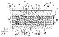
이 목적으로, 본 발명은, 그것의 제 1 독립 양태에 따라, 기재 및 그 위에 제공된 장식을 가지는 플로어 패널에 관련되고, 상기 기재는 적어도 열가소성 재료의 발포 층 및 적어도 보강 층을 포함하는 특징을 갖는다. 발명자는, 발포 층이 동일한 열가소성 재료의 비발포 층보다 양호한 치수 안정성을 가지는 것을 발견하였다. 더욱이, 발포 층으로, 보강 층은 온도 변화로 인한 가능한 치수 확장을 제한하기 위해 보다 효과적인 결과를 갖는다.To this end, the present invention relates, according to its first independent aspect, to a floor panel having a substrate and a decoration provided thereon, wherein the substrate is characterized in that it comprises at least a foamed layer of thermoplastic material and at least a reinforcing layer. . The inventors have found that a foamed layer has better dimensional stability than a non-foamed layer of the same thermoplastic material. Furthermore, with the foam layer, the reinforcing layer has a more effective result for limiting possible dimensional expansion due to temperature changes.
본 발명의 범위 내에서, "기재" 라고 하면 상기 장식 아래에 위치된 플로어 패널의 모든 부분들을 언급한다는 점에 주목한다. 발포 층이라고 하면, 바람직하게 재료의 밀도가 적어도 10%, 바람직하게 적어도 25% 만큼 감소된 양으로, 중공 공간들을 포함하는 층을 의도한다. 바람직하게, 이것은 소위 "폐쇄 셀" 폼에 관련된다. 비발포 층이라고 하면, 중공 공간들이 없거나, 여하튼 많아도 밀도가 감소되지 않거나 10% 이하 감소되고, 바람직하게 심지어 2% 이하 감소되도록 중공 공간들의 양을 갖는 층을 의미한다.It is noted that, within the scope of the present invention, reference to "substrate" refers to all parts of the floor panel located below the decoration. By foam layer, we mean a layer comprising hollow spaces, preferably in an amount in which the density of the material is reduced by at least 10%, preferably by at least 25%. Preferably, this relates to so-called "closed cell" foam. By non-foaming layer is meant a layer without hollow spaces or with an amount of hollow spaces such that the density is not reduced at all at most or is reduced by 10% or less, preferably even reduced by 2% or less.
일반적으로, 또한, 본 발명의 범위 내에서, 발포 층은 반드시 균일하게 발포될 필요가 없다는 점에 주목한다. 발포 층은, 그것의 두께를 가로질러, 가변 비율의 중공 공간들을 포함하는 것이 가능하다. 그래서, 예를 들어, 최고 비율은 층에서 중심에 달성될 수도 있고, 반면에 이러한 층의 면들 중 하나 이상에 덜 발포되거나 심지어 발포되지 않은 구역들이 존재할 수도 있다.It is noted that generally, also within the scope of the present invention, the foam layer need not necessarily be foamed uniformly. It is possible that the foam layer contains a variable proportion of hollow spaces across its thickness. So, for example, the highest proportion may be achieved centrally in a layer, while there may be less or even non-foamed areas on one or more of the faces of this layer.
각각의 발포 층은 바람직하게 기재에서 중심에 위치결정되거나, 환언하면, 기재의 두께 중심에 존재하는 적어도 기재 부분을 형성한다.Each foam layer is preferably positioned centrally in the substrate, or in other words forms at least a portion of the substrate that is centered in the thickness of the substrate.
각각의 발포 층은 바람직하게 상기 기재의 두께의 적어도 30% 를 형성한다. 바람직하게, 발포 층은 심지어 기재의 두께의 40% 이상을 형성한다.Each foam layer preferably forms at least 30% of the thickness of the substrate. Preferably, the foam layer even forms at least 40% of the thickness of the substrate.
복수의 발포 층들이 상기 기재에 존재할 수 있다는 점을 배제하지 않는 것은 분명하다. 발포 층들의 전체 두께는 바람직하게 플로어 패널의 두께의 30 내지 70%, 또는 기재의 두께의 25 내지 65% 이다.It is clear that it is not excluded that a plurality of foamed layers may be present in the substrate. The total thickness of the foam layers is preferably 30 to 70% of the thickness of the floor panel, or 25 to 65% of the thickness of the substrate.
바람직하게, 상기 발포 층은 발포 폴리 염화 비닐 (PVC) 층에 관련된다. 바람직하게, 이것은 소위 강성 PVC, 즉 가소제들이 없거나 12phr 이하의 가소제들의 함량을 함유하는 PVC 에 관련된다. 바람직하게, 가소제들의 함량은 1 내지 6 phr 이다. 이러한 경질 폼의 층의 스티프니스는 비발포 층의 것과 비슷하지만; 그러나, 그것의 낮은 중량 때문에 설치하는 동안 인체 공학적인 장점들을 제공한다. 본 발명은 PVC 의 발포 층들에 제한되지 않고, 또한 발포 층이 다른 열가소성 재료, 예로 페놀 폼, 폴리우레탄 폼, 폴리프로필렌 폼, 폴리에틸렌 폼 또는 폴리에틸렌 테레프탈레이트 폼으로 형성되는 플로어 패널들에 적용되는 것이 분명하다.Preferably, the foam layer relates to a layer of foamed polyvinyl chloride (PVC). Preferably, this relates to so-called rigid PVC, ie PVC which is free of plasticizers or contains a content of plasticizers of less than or equal to 12 phr. Preferably, the content of plasticizers is 1 to 6 phr. The stiffness of this layer of rigid foam is similar to that of the non-foam layer; However, it offers ergonomic advantages during installation due to its low weight. It is clear that the present invention is not limited to foam layers of PVC, but also applies to floor panels in which the foam layer is formed of other thermoplastic materials, such as phenolic foam, polyurethane foam, polypropylene foam, polyethylene foam or polyethylene terephthalate foam. Do.
바람직하게, 발포 층은 충전제 재료들, 예로 초크 또는 활석을 포함한다. 발명자는 토크 (talk) 가 더욱이 증가된 치수 안정성을 유발한다는 점을 발견하였다. 바람직하게, 적어도 30 phr 의 미네랄 충전제들이 상기 발포 층에 적용된다.Preferably, the foam layer contains filler materials, such as chalk or talc. The inventors have found that torque also leads to increased dimensional stability. Preferably, at least 30 phr of mineral fillers are applied to the foam layer.
발포 층은 다양한 가능한 방식들로 획득될 수 있고, 이들 중 하기에 3 가지 가장 중요한 가능성들이 열거된다.The foam layer can be obtained in a variety of possible ways, of which the three most important possibilities are listed below.
제 1 가능성에 따르면, 발포 층은 적어도 기계적 발포 프로세스에 의해 획득된다. 이로써, 이물질에 의해 열가소성 재료를 밀어냄으로써 각각의 층에 중공 공간들이 형성되는 것을 의미한다. 이것은, 예를 들어, PVC 기반 층에서 과립들을 팽창시키는 용도에 관련될 수도 있다. 보다 특히, WO 2013/178561 에 공지된 마이크로스피어들이 사용될 수 있다. 적어도 이런 제 1 가능성에 따라 획득된 플로어 패널은, 발포 층이 중공 공간들을 포함하고, 그것의 벽들은 각각의 팽창된 과립들의 벽들에 의해 코팅되는 것이 분명하다.According to a first possibility, the foam layer is obtained at least by a mechanical foaming process. This means that hollow spaces are formed in each layer by pushing the thermoplastic material by the foreign matter. This may relate, for example, to the use of expanding granules in a PVC-based layer. More particularly, microspheres known from WO 2013/178561 can be used. It is clear that the floor panel obtained according to at least this first possibility has the foam layer comprising hollow spaces, the walls of which are coated by the walls of the respective expanded granules.
제 2 가능성에 따르면, 발포 층은 적어도 화학적 발포 프로세스에 의해 획득된다. 이것은 가스 반응 생성물에 의해 각각의 층에 중공 공간들이 형성되는 것을 의미한다. 예를 들어, 아조디카본아미드가 사용될 수 있다. 이 재료는, 워밍 업 (warming up) 할 때, 버블들 형태로 발포 층에 여전히 존재하는 질소 가스를 방출한다.According to a second possibility, the foam layer is obtained at least by a chemical foaming process. This means that hollow spaces are formed in each layer by gaseous reaction products. For example, azodicarbonamides may be used. This material, when warming up, releases nitrogen gas that is still present in the foam layer in the form of bubbles.
제 3 가능성에 따르면, 발포 층은 적어도 충전제들에 의해 획득되고, 이 충전제들은 이와 같이 하나 이상의 중공 공간들을 포함한다. 본원에서, 예를 들어, 이미 언급된 마이크로스피어들의 팽창된 상태가 이용될 수 있다.According to a third possibility, the foam layer is obtained at least by fillers, which fillers thus comprise one or more hollow spaces. Here, for example, the already mentioned expanded state of microspheres can be used.
바람직하게, 전술한 보강 층은 직조 또는 부직 유리 섬유 층과 같은 유리 섬유 층에 관련된다. 바람직하게, 이러한 보강 층 또는 유리 섬유 층은 적어도 30 g/㎡, 바람직하게 100 g/㎡ 미만의 중량을 갖는다. 더 양호하게는, 유리 섬유 층의 보강 층의 중량은 35 내지 65 g/㎡ 의 중량에 관련되고, 여기서 50 g/㎡ 가 양호한 값이다.Preferably, the aforementioned reinforcing layer relates to a glass fiber layer, such as a woven or non-woven glass fiber layer. Preferably, this reinforcing layer or glass fiber layer has a weight of at least 30 g/
전술한 보강 층은 바람직하게 발포 층의 면들 중 하나에 위치된다. 그 위치에서, 보강 층은 발포 층의 각각의 면의 천공 또는 변형 위험을 제한할 수도 있고, 보강 층은 각각의 면의 벌징 (bulging) 에 대해 증가된 저항을 유발한다. 바람직하게, 각각의 보강 층은 전술한 장식을 향한 발포 층의 면에 위치된다. 이런 식으로, 예를 들어, 의자 또는 테이블 다리들에 의해, 인덴테이션에 대해 증가된 저항을 획득한다.The aforementioned reinforcing layer is preferably located on one of the faces of the foam layer. In that position, the reinforcing layer may limit the risk of puncture or deformation of each side of the foam layer, and the reinforcing layer causes increased resistance to bulging of each side. Preferably, each reinforcing layer is located on the side of the foam layer facing the above-mentioned decoration. In this way, an increased resistance to indentation is obtained, for example by chair or table legs.
가장 바람직한 실시형태에 따르면, 상기 기재는 추가로 제 2 보강 층도 둘러싼다. 2 개의 보강 층들은 바람직하게 상기 발포 층의 적어도 일부분을 둘러싸고 이런 식으로 양 면에서 상기 변형 저항 효과를 제공한다. 바람직하게, 2 개의 보강 층들은 동일한 종류이고, 예를 들어, 양자는 중량이 30 내지 75 g/㎡ 인 유리 섬유 층들이다. 발명자의 기대에 반하여, 그는 치수 안정성 개선을 고려해 가능한 한 높게 별개의 보강 층들의 중량 또는 강도를 선택하기 보다는 2 개의 보강 층들을 적용하는 것이 더 중요하다는 것을 발견하였다. 따라서, 제한된 중량의 2 개의 보강 층들이 사용될 수도 있고, 이것은 경제적으로 유리하다. 그래서, 예를 들어, 50 g/㎡, 또는 대략 50 g/㎡ 의 2 개의 유리 섬유 층들이 사용될 수도 있다.According to a most preferred embodiment, the substrate additionally also encloses a second reinforcing layer. The two reinforcing layers preferably surround at least a part of the foam layer and in this way provide the strain resistance effect on both sides. Preferably, the two reinforcing layers are of the same kind, for example both glass fiber layers with a weight of 30 to 75 g/
일반적으로, 1 개보다 많은 보강 층이 플로어 패널에 존재하는 경우에, 본원의 보강 층들의 전체 중량은 바람직하게 150 g/㎡ 미만이라는 점에 또한 주목한다.It is also noted that, in general, if more than one reinforcing layer is present in the floor panel, the total weight of the reinforcing layers herein is preferably less than 150 g/
중요한 실시형태에 따르면, 상기 기재는 바람직하게 적어도 열가소성 재료의 아직 발포되지 않은 층도 추가로 포함한다. 이러한 비발포 층은 바람직하게 그것이 전부 중심 밖에 위치되도록 기재 내 위치에 있다. 상기한 바와 같이, 그것은 바람직하게 기재에서 중심에 위치결정되는 발포 층이다. 또한, 본 발명에 따르면, 발포 층 및 보강 층을 포함하는 플로어 패널에서 비발포 층의 가용성은 텔레그래피 효과들에 대한 장벽을 형성하고, 이런 비발포 층의 위치에 따라, 다양한 다른 장점들을 이끌 수도 있다.According to an important embodiment, the substrate preferably further comprises at least an as-yet-unfoamed layer of thermoplastic material. This non-foaming layer is preferably positioned within the substrate such that it is entirely off-center. As mentioned above, it is preferably a foam layer positioned centrally in the substrate. Furthermore, according to the present invention, the availability of a non-foam layer in a floor panel comprising a foam layer and a reinforcing layer forms a barrier against telegraphic effects and, depending on the location of this non-foam layer, may lead to various other advantages. there is.
바람직하게, 전술한 비발포 층은 전술한 발포 층의 면들 중 하나 및/또는 가능하다면 발포 층의 면에 제공된 보강 층에 인접해 있다. 각각의 면이 상기 장식을 향하는 경우에, 상기 비발포 층에 의해 인덴테이션에 대한 부가적 저항이 획득된다. 장식이 이런 식으로 보다 안정적인 밑에 있는 면에 제공된 경우에, 플로어 패널의 내충격성은 전체적으로 개선된다.Preferably, the aforementioned non-foamed layer is adjacent to a reinforcing layer provided on one of the faces of the aforementioned foamed layer and/or possibly on the face of the foamed layer. Additional resistance to indentation is obtained by the non-foaming layer when the respective side faces the decoration. When decoration is provided in this way to a more stable underlying surface, the impact resistance of the floor panel as a whole is improved.
상기한 바와 같이, 비발포 층은 바람직하게 기재의 중심에서 벗어나 위치결정된다. 이런 식으로, 기재, 따라서 전체 플로어 패널의 증가된 굽힘 스티프니스가 획득된다.As noted above, the non-foaming layer is preferably positioned off-center of the substrate. In this way, increased bending stiffness of the substrate and thus of the entire floor panel is obtained.
바람직하게, 전술한 비발포 층은 전술한 발포 층과 동일한 열가소성 재료를 함유하거나 동일한 열가소성 재료를 기반으로 한다. 물론, 그것은 상이한 함량의 첨가제들, 예로 가소제들 및/또는 충전제들을 가질 수도 있다.Preferably, the aforementioned non-foamed layer contains or is based on the same thermoplastic material as the aforementioned foamed layer. Of course, it may have different contents of additives, eg plasticizers and/or fillers.
바람직하게, 상기 비발포 층은 가소제들이 없고 12 phr 미만, 더 양호하게는 7 phr 미만인 가소제들의 함량을 포함한다.Preferably, the non-foaming layer is free of plasticizers and contains a content of plasticizers less than 12 phr, better still less than 7 phr.
폴리 염화 비닐에 적합한 가소제들은, 무엇보다도, DINP, DOTP 및 DINCH 에 관련된다.Plasticizers suitable for polyvinyl chloride relate, among other things, to DINP, DOTP and DINCH.
중요한 실시형태에 따르면, 전술한 기재는 적어도 열가소성 재료의 제 2 비발포 층도 추가로 포함하고, 각각의 비발포 층들은 상기 발포 층의 적어도 일부분을 둘러싼다. 이 실시형태에 따르면, 경량이면서 여전히 높은 굽힘 스티프니스를 보이는 기재의 흥미로운 조성을 얻는다. 더욱이, 이러한 조성은 안정적인 기재 또는 기재 부분을 유발한다. 바람직하게, 상기 기재는 적어도 열가소성 재료의 제 3 비발포 층을 추가로 포함하고, 상기 제 3 비발포 층은 장식과 전술한 제 1 및 제 2 비발포 층들 중 적어도 하나 사이에 위치된다. 바람직하게, 제 3 비발포 층은 장식과 발포 층 전체와 제 1 및 제 2 비발포 층들 사이에 위치된다. 전술한 제 3 비발포 층의 특징들, 보다 특히 그것의 유연성 또는 압축성은 상기 제 3 비발포 층의 원하는 기능과 일치할 수 있다. 그래서, 예를 들어, 그것은 가능하다면 상기 제 1 및/또는 제 2 비발포 층에 존재하는 가소제의 함량보다 높은 가소제의 함량을 포함할 수도 있다. 이러한 층이 장식과 발포 층 전체와 제 1 및 제 2 비발포 층들 사이 위치에 있을 때, 그것은 보행 편안함을 증가시키는 임의의 소리 감쇠를 가져올 수 있고, 제조 기술 면에서 장점들을 제공한다. 그래서, 예를 들어, 플로어 패널 면에 제공되는 인덴테이션들은 이런 제 3 비발포 층으로 계속될 수도 있고, 인덴테이션들은 0.1 ㎜ 초과 또는 심지어 0.4 ㎜ 이상의 깊이로 획득될 수 있다. 이러한 경우에, 전술한 제 3 비발포 층은 바람직하게 전술한 장식 바로 아래에, 또는 적어도 장식 아래 0.15 ㎜ 미만의 거리에 위치된다. 이러한 인덴테이션들로, 상기 장식 그 자체는 또한 평면 밖으로 이동되어서, 예를 들어, 우드 또는 스톤 면들의 매우 효과적인 모조품들을 얻을 수 있다According to an important embodiment, the aforementioned substrate further comprises at least a second non-foamed layer of thermoplastic material, each non-foamed layer enclosing at least a portion of said foamed layer. According to this embodiment, an interesting composition of a substrate that is lightweight and still exhibits high bending stiffness is obtained. Moreover, these compositions lead to stable substrates or substrate parts. Preferably, the substrate further comprises at least a third non-foaming layer of thermoplastic material, the third non-foaming layer being positioned between the decoration and at least one of the aforementioned first and second non-foaming layers. Preferably, the third non-foaming layer is located between the entire decoration and foaming layer and the first and second non-foaming layers. The aforementioned characteristics of the third non-foaming layer, more particularly its flexibility or compressibility, may match the desired function of the third non-foaming layer. So, for example, it may possibly contain a content of plasticizer higher than the content of plasticizer present in the first and/or second non-foaming layer. When this layer is positioned between the first and second non-foamed layers as well as the entire decorative and foamed layer, it can result in some sound attenuation that increases walking comfort and offers advantages in terms of manufacturing technology. So, for example, indentations provided on the floor panel face may continue with this third non-foaming layer, and indentations may be obtained with a depth greater than 0.1 mm or even greater than 0.4 mm. In this case, the above-mentioned third non-foaming layer is preferably located directly below the above-mentioned decoration, or at least at a distance of less than 0.15 mm below the decoration. With these indentations, the decoration itself can also be moved out of plane, obtaining very effective imitations of, for example, wood or stone faces.
일반적으로, 상기 기재는 바람직하게 열가소성 재료의 적어도 다른 층도 추가로 포함하고, 상기 열가소성 재료는 상기 발포 층에서 가능한 가소제 함량보다 많은 함량을 갖는 가소제들을 함유한다. 본원에서, 이것은 가능하다면 상기 제 3 비발포 층에 관련될 수도 있다. 하지만, 상기 제 1 및/또는 제 2 비발포 층들이 존재하지 않을 때 이러한 층이 또한 관심을 받는 것은 분명하다. 더욱이, 보다 높은 가소제 함량을 갖는 층은 가능하다면 발포될 수도 있지만, 반드시 그럴 필요는 없다. 바람직하게, 보다 높은 가소제 함량을 갖는 상기 층은 상기 발포 층과 상기 장식 사이에 위치된다. 이런 식으로, 제 3 비발포 층과 관련하여 본원에서 전술한, 소리 감쇠 장점들 및 기술 제조 면에서 장점들이 여기에서 또한 달성될 수 있다. 바람직하게, 보다 높은 가소제 함량을 갖는 상기 층은 상기 발포 층과 동일한 열가소성 재료, 즉 바람직하게 폴리 염화 비닐 (PVC) 을 함유한다. 바람직하게, 보다 높은 가소제 함량을 갖는 상기 층은 발포되지 않는다.In general, the substrate preferably also further comprises at least another layer of thermoplastic material, said thermoplastic material containing plasticizers having a higher plasticizer content than is possible in the foam layer. Here, this may possibly relate to the third non-foamed layer. However, it is clear that this layer is also of interest when said first and/or second non-foaming layers are not present. Moreover, layers with higher plasticizer content may be foamed if possible, but need not be. Preferably, the layer with a higher plasticizer content is located between the foam layer and the decoration. In this way, the sound damping advantages and the advantages in terms of manufacturing technology, described above in relation to the third non-foaming layer, can also be achieved here. Preferably, the layer with a higher plasticizer content contains the same thermoplastic material as the foam layer, ie preferably polyvinyl chloride (PVC). Preferably, the layer with higher plasticizer content is not foamed.
가장 바람직한 실시형태에 따르면, 기재는 열가소성 재료, 바람직하게 12 phr 미만의 가소제 함량을 가지거나 가소제가 없는 PVC 의 발포 층을 포함하고, 상기 기재는 또한 매번 바람직하게 12 phr 미만의 가소제 함량을 갖는 PVC 의 발포 층의 양 면에 하나 이상의 비발포 층들도 추가로 포함하고, 일 면 상의 모든 비발포 층들의 두께 대 발포 층의 다른 면 상의 비발포 층들의 두께의 비는 0.6 내지 1.70, 또는 더 양호하게는 0.75 내지 1.33 이다. 발포 층 아래와 위의 이런 비발포 층들 전체를 대략 동일한 두께로 하거나, 적어도 상기 비 내에서 비슷한 두께를 가지게 함으로써, 안정적인 샌드위치가 생성된다. 바람직하게, 하부면에서 비발포 층들 전체는 발포 층의 상부 면에서 비발포 층들 전체보다 더 얇지만, 상기 비 내에 있다. 이러한 경우에 상부면에서 비발포 층들의 평균 가소제 함량은 바람직하게 하부면에서 비발포 층들의 평균 가소제 함량보다 높다. 본 발명에 따르면, 기재는 또한 적어도 보강 층을 둘러싸는 것이 분명하다. 바람직하게, 적어도 2 개의 보강 층들이 적용되고, 즉 바람직하게 매번 전술한 발포 층의 면마다 1 개가 적용된다. 그러면, 이 보강 층들은 바람직하게 매번 발포 층과 비발포 층들의 전술한 전체 사이에 분리를 형성한다.According to a most preferred embodiment, the substrate comprises a foamed layer of a thermoplastic material, preferably PVC with a plasticizer content of less than 12 phr or no plasticizer, said substrate also each time preferably PVC with a plasticizer content of less than 12 phr further comprising one or more non-foaming layers on both sides of the foam layer of the foam layer, wherein the ratio of the thickness of all non-foam layers on one side to the thickness of the non-foam layers on the other side of the foam layer is from 0.6 to 1.70, or better still. is from 0.75 to 1.33. By having all of these non-foamed layers above and below the foam layer be of approximately the same thickness, or at least similar in thickness within the ratio, a stable sandwich is created. Preferably, all of the non-foam layers at the bottom side are thinner than all of the non-foam layers at the top side of the foam layer, but within the ratio. In this case the average plasticizer content of the non-foaming layers on the top side is preferably higher than the average plasticizer content of the non-foaming layers on the bottom side. According to the invention, it is clear that the substrate also surrounds at least the reinforcing layer. Preferably, at least two reinforcing layers are applied, ie preferably one on each side of the aforementioned foam layer. These reinforcing layers then preferably each time form a separation between the aforementioned total of the foamed and non-foamed layers.
바람직하게, 상기 장식은 프린팅된 모티프를 포함한다. 이러한 프린팅된 모티프는 열가소성 포일, 예를 들어, PVC 포일에 제공될 수 있다. 본 발명의 범위 내에서, 이러한 포일은, 본원의 경우에, 전술한 장식의 구성요소로서 보이고 따라서 기재의 부분으로 보이지 않는다. 포일을 사용하는 대신에, 예를 들어, 백색 PVC 플라스티솔에 의해, 프라이머 층들을 매개로, 기재에 수행되는 프린트가 이용될 수도 있고, 이 프라이머 층들은, 본 발명의 범위 내에서 본원의 경우에, 따라서 상기 장식의 형성 부분으로 또한 고려된다.Preferably, the decoration comprises a printed motif. Such printed motifs may be provided on thermoplastic foils, for example PVC foils. Within the scope of the present invention, such a foil is, in the present case, seen as a component of the above-mentioned decoration and therefore not seen as part of the substrate. Instead of using a foil, a print carried out on a substrate, for example by means of a white PVC plastisol, via primer layers may be used, which primer layers are hereby within the scope of the present invention. , is therefore also considered as a forming part of the decoration.
바람직하게, 프린팅된 모티프는 우드 너브들 및/또는 스톤의 패턴에 관련된다. 바람직하게, 플로어 패널은 단 하나의 우드 판자의 모티프를 나타낸다.Preferably, the printed motif relates to a pattern of wood nubs and/or stones. Preferably, the floor panel exhibits a motif of only one wood plank.
비록 프린팅된 모티프들이 바람직하지만, 장식은, 예를 들어, 실제 우드의 베니어 또는 실제 스톤의 베니어에 의해, 또는 분말들, 예를 들어, PVC 분말들 또는 PVC 과립들의 압밀된 혼합물에 의해 형성될 수 있다는 것은 배제되지 않는다.Although printed motifs are preferred, the decoration may be formed, for example, by a veneer of real wood or of real stone, or by a compacted mixture of powders, for example PVC powders or PVC granules. It is not excluded that there is
바람직하게, 플로어 패널은 상기 장식 위에 제공되는 반투명 또는 투명한 마모 층도 추가로 포함한다. 바람직하게, 이러한 마모 층은 실질적으로, 예를 들어, 0.15 내지 0.75 ㎜ 의 두께를 갖는 열가소성 재료, 바람직하게 PVC 로 구성된다. 하지만, 이러한 마모 층은 바람직하게 표면 래커 층을 또한 나타낸다. 적합한 래커 층들의 예로는 우레탄 아크릴레이트들, 폴리에스테르 아크릴레이트들 및/또는 에폭시드 아크릴레이트들을 기반으로 한 래커 층들이다. 바람직하게, 이것은 UV 방사선 또는 엑시머 방사선에 의해 경화되는 래커 층들에 관련된다. 각각의 래커 층은 증가된 내마모성을 달성하기 위해서, 예를 들어, 산화 알루미늄 및/또는 실리카의 경질 입자들을 포함할 수 있다.Preferably, the floor panel further comprises a translucent or transparent wear layer provided over said decoration. Preferably, this wear layer consists essentially of a thermoplastic material, preferably PVC, having a thickness of, for example, between 0.15 and 0.75 mm. However, this wear layer preferably also represents a surface lacquer layer. Examples of suitable lacquer layers are lacquer layers based on urethane acrylates, polyester acrylates and/or epoxide acrylates. Preferably, this relates to lacquer layers that are cured by means of UV radiation or excimer radiation. Each lacquer layer may include, for example, hard particles of aluminum oxide and/or silica to achieve increased wear resistance.
낮은 가소제 함량을 가지거나 가소제가 없는 하나 이상의 층들이 보강 층과 장식 사이에 위치되는 본 발명의 실시형태들은 래커 층의 선택과 관련하여 특별한 장점들을 제공한다는 점에 주목한다. 더 정확히 말해서, 그것은 보다 효율적인 래커 층을 위해 선택될 수도 있고, 반면에 원치 않는 부작용의 위험이 여전히 제한적이다. 더 정확히 말해서, 보다 효과적인 래커 층들은 임의의 수축을 나타낼 것이고 결과적으로 연질 기재들이 적용된 경우에 상승된 에지들을 이끌 수도 있다. 플로어 패널 면 가까이에 가소제가 없거나 제한된 함량, 예를 들어, 12 phr 미만 또는 7 phr 미만의 가소제를 갖는 층들의 존재는 이런 위험을 제한한다. 효율적인 래커에 대한 좋은 선택은 15 중량% 초과 또는 심지어 25 중량% 이상의, 산화 알루미늄 및/또는 실리카와 같은, 경질 입자들의 함량을 갖는, 우레탄 아크릴레이트를 기반으로 한 래커이다. 래커 층은 통상적인 것보다 더 두껍게 만들 수도 있고, 예를 들어, 20 ㎛ 보다 큰 두께를 가져서, 그것은 더 오래 효과적으로 유지될 것이다. 래커 층의 더 큰 두께는 또한 더 조대한 경질 입자들을 적용할 수 있도록 허용하고, 이것은 그러면 내마모성에 관하여 유리하다. 바람직하게, 10 ㎛ 초과의 평균 입도를 가지는 경질 입자들이 적용된다.It is noted that embodiments of the present invention in which one or more layers, either with a low plasticizer content or no plasticizer, are placed between the reinforcing layer and the decoration, provide special advantages with respect to the choice of the lacquer layer. More precisely, it may be chosen for a more efficient lacquer layer, while the risk of undesirable side effects is still limited. More precisely, more effective lacquer layers will exhibit any shrinkage and consequently may lead to raised edges when soft substrates are applied. The presence of layers with no or limited amounts of plasticizer, eg less than 12 phr or less than 7 phr plasticizer near the floor panel face, limits this risk. A good choice for an efficient lacquer is a lacquer based on urethane acrylates with a content of hard particles, such as aluminum oxide and/or silica, greater than 15% by weight or even greater than 25% by weight. The lacquer layer may be made thicker than usual, for example having a thickness greater than 20 μm, so that it will remain effective longer. The greater thickness of the lacquer layer also allows coarser hard particles to be applied, which is then advantageous in terms of wear resistance. Preferably, hard particles having an average particle size of greater than 10 μm are applied.
바람직하게, 상기 플로어 패널, 바람직하게 기재는, 두께로 볼 때, 가소제들이 없거나 12 phr 미만 또는 더 양호하게는 7 phr 미만의 가소제 함량을 보이는 적어도 2 ㎜ 의 열가소성 재료를 포함한다. 발명자는, 경질 열가소성 재료의 이 양은 가장 중요한 텔레그래피 효과들을 배제하기에 충분하다는 점을 발견하였다. 본 발명에 따르면, 이 두께는 발포 또는 비발포 층들에 의해 형성될 수 있다는 점은 분명하다.Preferably, the floor panel, preferably the substrate, comprises at least 2 mm of thermoplastic material, in terms of thickness, free of plasticizers or exhibiting a plasticizer content of less than 12 phr or better still less than 7 phr. The inventor has found that this amount of hard thermoplastic material is sufficient to eliminate the most important telegraphic effects. It is clear that according to the invention this thickness can be formed by foamed or non-foamed layers.
바람직하게, 플로어 패널은, 두께로 볼 때, 최대 5, 또는 더 양호하게는 최대 3 ㎜ 의 발포형 열가소성 재료를 포함한다. 바람직하게, 본 발명의 발포 층은 최대 4 ㎜ 의 두께를 나타내고, 상기 발포 층은 그러면, 상기한 바와 같이, 바람직하게 기재에서 중심에 존재한다.Preferably, the floor panel comprises at most 5, or better still at most 3 mm of foamed thermoplastic material, in terms of thickness. Preferably, the foam layer of the invention presents a thickness of at most 4 mm, said foam layer then, as described above, preferably centered on the substrate.
바람직하게, 상기 기재는, 그 두께의 적어도 40% 에 대해, 상기 발포 층으로 구성되고, 잔류하는 기재 재료는 바람직하게 발포되지 않는다. 대안으로서, 기재는, 그것의 하부면 가까이에, 부가적 발포 층을 또한 나타낼 수 있고, 이것은 제 1 발포 층의 두께에 독립적이고, 이 층은 바람직하게, 상기한 바와 같이, 기재에서 중심에 위치결정된다. 상기 부가적 발포 층은 바람직하게 열가소성 재료를 또한 포함한다. 그것이 발포 층과 동일한 열가소성 재료로 구성되는 것을 배제하지 않지만, 그것은 바람직하게 폴리에틸렌을 기반으로 한 발포 층의 재료에 독립적이다. 이것은, 예를 들어, 0.7 ~ 3 ㎜ 의 두께를 가지는 가교 결합되거나 상호 연결된 폴리에틸렌 (XPE) 의 층에 관련될 수도 있다.Preferably, the substrate consists, for at least 40% of its thickness, of the foamed layer, and the remaining substrate material is preferably not foamed. Alternatively, the substrate may also present, near its lower face, an additional foam layer, which is independent of the thickness of the first foam layer, which layer is preferably centrally located in the substrate, as described above. It is decided. The additional foam layer preferably also comprises a thermoplastic material. It is independent of the material of the foam layer, which is preferably based on polyethylene, although it is not excluded that it is composed of the same thermoplastic material as the foam layer. This may relate, for example, to a layer of cross-linked or interconnected polyethylene (XPE) having a thickness of 0.7 to 3 mm.
다양한 기재 층들은 많은 다른 방식으로 구현될 수 있고 열적 라미네이팅 프로세스에 의해 서로 위에 부착될 수 있다. 기재가 그것의 밑면에 부가적 발포 층을 나타내는 경우에, 이 층은 바람직하게 글루 (glue) 연결에 의해 잔류하는 기재 부분들에 부착된다.The various substrate layers can be implemented in many different ways and can be attached over one another by a thermal laminating process. If the substrate presents an additional foam layer on its underside, this layer is preferably attached to the remaining substrate parts by means of glue connections.
바람직하게, 기재의 열가소성 층들 하나 이상은, 과립 형태든 아니든, 적어도 전술한 열가소성 재료를 스트로잉 및 압밀함으로써 획득된다. 플로어 패널들을 제조하기 위한 스트로잉 처리들은 이와 같이, 예를 들어, WO 2013/179261 에 공지되어 있다.Preferably, one or more of the thermoplastic layers of the substrate are obtained by stroking and compacting at least the aforementioned thermoplastic material, whether in granular form or otherwise. Strawing treatments for producing floor panels are known as such, for example from WO 2013/179261.
본 발명의 플로어 패널들은 바람직하게 플로팅 플로어 커버링을 구현하기 위해 적용될 수 있다. 이 목적으로, 상기 패널들은 하나 이상의 에지들에 프로파일들을 구비할 수도 있다. 본 발명의 플로어 패널들의 층 조성은 이러한 프로파일들의 실제 형태와 다양한 시너지 효과들을 나타낼 수도 있다. 이하, 이러한 프로파일들의 다수의 바람직한 특징들이 열거될 것이다.The floor panels of the present invention can advantageously be applied to realize a floating floor covering. For this purpose, the panels may have profiles on one or more edges. The layer composition of the floor panels of the present invention may exhibit various synergistic effects with the actual form of these profiles. In the following, a number of desirable features of these profiles will be listed.
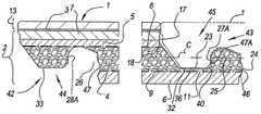
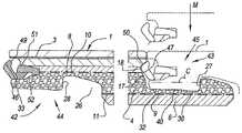
바람직하게, 본 발명의 플로어 패널은, 적어도 2 개의 대향한 에지들 상에서, 그것은 2 개의 이러한 플로어 패널들을 함께 결합할 수 있는 결합 수단을 구비하고, 각각의 에지들에서 적어도 상기 패널들의 평면에 수직인 수직 방향으로 로킹이 이루어지고, 전술한 에지들 중 적어도 하나는 그루브를 구비하고, 상기 그루브의 가장 깊은 지점은 상기 발포 층에 위치되는 특징을 나타낸다. 발포 재료에 적어도 부분적으로 그루브를 구현하면 치수 안정성에 대해 장점들을 제공한다. 바람직하게, 상기 보강 층은 전술한 그루브의 경계를 이루는 립들 중 하나에 중단됨이 없이 연장된다. 기재가 2 개의 보강 층들을 나타내는 경우에, 그것들은 바람직하게 각각 상기 립들 중 하나의 적어도 일부분에 연장되고, 즉 하나는 상부 그루브 립에 연장되고 하나는 하부 그루브 립에 연장된다. 바람직하게, 보강 층들은 적어도 그루브 개구까지 연속되고, 즉 거기에, 각각의 립들 중 가장 짧은 것의 원위 단부가 위치된다. 이런 마지막 가능성에 따르면, 플로어 패널들 사이에 매우 안정적인 수직 로킹이 획득되고, 플로어 패널들의 면에서 상승된 에지들의 위험이 최소화된다. 각각의 그루브는 바람직하게 유사한 플로어 패널의 대향한 에지에서 텅과 협동작용하거나 또한 유사한 플로어 패널의 대향한 에지와 협동작용하는 별개의 연결 피스와 협동작용한다는 점은 분명하다. 두 경우에 이러한 플로어 패널들 중 2 개가 결합된 상태에서 바람직하게 한 쌍 이상의 수직 활성 로킹 면들이 생성된다. 바람직하게, 이러한 적어도 한 쌍은 전술한 그루브에, 즉 하나 또는 양 그루브 립들에 위치되고, 상기 보강 층 또는 보강 층들은 그러면 바람직하게 각각의 쌍의 수직 활성 로킹 면들 아래까지 중단됨이 없이 연장된다. 바람직하게, 상기 쌍들 중 적어도 한 쌍, 더 양호하게는 두 쌍의 수직 활성 로킹 면들이 전술한 발포 층의 재료에 형성된다. 각각의 접촉면들에서 임의의 장력이 사용될 수 있고, 이것에 의해 매우 안정적인 연결을 얻는다. 이러한 장력은, 예를 들어, 이런 접촉면들의 로케이션에 과도한 재료를 제공함으로써 구현될 수도 있다. 보강 층 또는 층들 및 가능한 비발포 층들의 위치에 대한 좋은 선택에 의해, 가능한 장력이 플로어 패널의 표면을 향하여 전파되는 것이 방지될 수도 있다.Preferably, the floor panel of the present invention has, on at least two opposite edges, it has joining means capable of joining two such floor panels together, and at each of the edges at least perpendicular to the plane of said panels. It is characterized by locking in the vertical direction, at least one of the aforementioned edges having a groove, the deepest point of the groove being located in the foam layer. Implementing grooves at least partially in a foam material provides advantages with respect to dimensional stability. Preferably, the reinforcing layer extends without interruption to one of the ribs bordering the aforementioned groove. Where the substrate exhibits two reinforcing layers, they preferably each extend at least a portion of one of the ribs, ie one extends to the upper groove lip and one to the lower groove lip. Preferably, the reinforcing layers are continuous at least to the groove opening, ie the distal end of the shortest of the respective ribs is located there. According to this last possibility, a very stable vertical locking between the floor panels is obtained and the risk of raised edges in the face of the floor panels is minimized. It is clear that each groove preferably cooperates with a tongue at opposite edges of a similar floor panel or with a separate connecting piece that also cooperates with opposite edges of a similar floor panel. In both cases, with two of these floor panels joined, preferably at least one pair of vertically active locking surfaces is created. Preferably, such at least one pair is located in the aforementioned groove, ie in one or both groove ribs, and the reinforcing layer or reinforcing layers then preferably extend uninterruptedly down to the vertical active locking surfaces of each pair. Preferably, at least one pair of said pairs, better still two pairs of vertically active locking surfaces, are formed in the material of the aforementioned foam layer. Any tension can be used at the respective contact surfaces, thereby obtaining a very stable connection. Such tension may be implemented, for example, by providing excess material at the location of these contact surfaces. By good choice of the position of the reinforcing layer or layers and possible non-foam layers, possible tension may be prevented from propagating towards the surface of the floor panel.
바람직하게, 본 발명의 플로어 패널은, 적어도 2 개의 대향한 에지들 상에서, 그것은 이러한 플로어 패널들 중 2 개를 서로 결합할 수 있는 결합 수단을 구비하고, 각각의 에지들에서 상기 에지들에 수직이고 적어도 상기 패널들의 평면에서 수평 방향으로 로킹이 이루어지고, 전술한 에지들 중 적어도 하나는 상향 후크형 로킹 부분을 구비하고, 상기 로킹 부분은 상기 발포 층이 없는 기재의 부분에 적어도 부분적으로 연장되는 특징을 나타낸다. 이 특징에 의하여, 명확한 수평 로킹을 얻는다. 더 정확히 말해서, 비발포 층들은 더 높은 정밀도로 처리될 수 있다.Preferably, the floor panel of the present invention, on at least two opposite edges, it has coupling means capable of coupling two of these floor panels to each other, and at each of the edges perpendicular to said edges and characterized in that at least in the plane of the panels the locking is carried out in a horizontal direction, and at least one of the aforementioned edges has an upwardly hooked locking portion, the locking portion extending at least partially to the portion of the substrate without the foam layer. indicates By this feature, a clear horizontal locking is obtained. More precisely, non-foamed layers can be processed with higher precision.
바람직하게, 본 발명의 플로어 패널은, 적어도 2 개의 대향한 에지들 상에서, 그것은 이러한 플로어 패널들 중 2 개를 서로 결합할 수 있는 결합 수단을 구비하고, 각각의 에지들에서 적어도 상기 패널들의 평면에 수직인 수직 방향으로 로킹이 이루어지고, 전술한 에지들 중 적어도 하나는 그루브를 구비하고, 상기 그루브는 상부 립 및 하부 립에 의해 경계를 이루고 상기 하부 립의 상부면은 상기 발포 층에 적어도 부분적으로 형성되는 특징을 나타낸다. 언급한 대로, 양호한 치수 안정성을 보여주므로 하부 립을 이 재료에 제공하는 것이 유리하다. 이런 특징은 개선된 기계적 결합을 이끌고, 결합된 에지들 사이에 간극이 형성되는 위험이 제한된다. 물론, 하부 립의 전술한 상부면은 또한 적어도 부분적으로 상기 발포 층이 없는 기재의 부분, 예를 들어, 수평 방향으로 가능한 로킹에 관여하는 상부면의 부분에 형성되는 것을 배제하지 않는다.Preferably, the floor panel of the present invention, on at least two opposite edges, it has coupling means capable of coupling two of these floor panels to each other, and at each of the edges at least in the plane of the panels. Locking is effected in a perpendicular vertical direction, wherein at least one of the aforementioned edges has a groove, the groove being bounded by an upper lip and a lower lip, the upper surface of the lower lip being at least partially in the foam layer. characterizes the formation. As mentioned, it is advantageous to provide this material with a lower lip as it shows good dimensional stability. This feature leads to improved mechanical bonding and limits the risk of gaps forming between bonded edges. Of course, it is not excluded that the above-mentioned upper surface of the lower lip is also formed at least partially in the part of the substrate without the foam layer, for example in the part of the upper surface involved in possible locking in the horizontal direction.
바람직하게, 본 발명의 플로어 패널은, 적어도 2 개의 대향한 에지들 상에서, 그것은 이러한 플로어 패널들 중 2 개를 서로 결합할 수 있는 결합 수단을 구비하고, 각각의 에지들에서 적어도 상기 패널들의 평면에 수직인 수직 방향으로 로킹이 이루어지고, 전술한 에지들 중 적어도 하나는 그루브를 구비하고, 상기 그루브는 상부 립 및 하부 립에 의해 경계를 이루고 상기 상부 립의 하부면은 상기 발포 층에 적어도 부분적으로 형성되는 특징을 나타낸다.Preferably, the floor panel of the present invention, on at least two opposite edges, it has coupling means capable of coupling two of these floor panels to each other, and at each of the edges at least in the plane of the panels. Locking is effected in a vertical vertical direction, wherein at least one of the aforementioned edges has a groove, the groove being bounded by an upper lip and a lower lip, the lower surface of the upper lip being at least partially in contact with the foam layer. characterizes the formation.
바람직하게, 본 발명의 플로어 패널은, 적어도 2 개의 대향한 에지들 상에서, 그것은 이러한 플로어 패널들 중 2 개를 서로 결합할 수 있는 결합 수단을 구비하고, 각각의 에지들에서 적어도 상기 패널들의 평면에 수직인 수직 방향으로 로킹이 이루어지고, 전술한 에지들 중 적어도 하나는 그루브를 구비하고, 상기 그루브는 상부 립 및 하부 립에 의해 경계를 이루고 상기 상부 립의 하부면은 상기 발포 층이 없는 상기 기재의 부분에 적어도 부분적으로 형성되는 특징을 나타낸다.Preferably, the floor panel of the present invention, on at least two opposite edges, it has coupling means capable of coupling two of these floor panels to each other, and at each of the edges at least in the plane of the panels. locking in the perpendicular vertical direction, at least one of the aforementioned edges having a groove, the groove being bounded by an upper lip and a lower lip, the lower surface of the upper lip being the substrate without the foam layer; It is characterized by being at least partially formed on the part of.
바람직하게, 본 발명의 플로어 패널은, 적어도 2 개의 대향한 에지들 상에서, 그것은 이러한 플로어 패널들 중 2 개를 서로 결합할 수 있는 결합 수단을 구비하고, 각각의 에지들에서 적어도 상기 패널들의 평면에 수직인 수직 방향 뿐만 아니라 각각의 에지들에 수직이고 상기 플로어 패널들의 평면에서 수평 방향으로 로킹이 이루어지고, 수직 방향으로 상기 로킹은 상기 발포 층에 형성된 적어도 한 쌍의 협동작용하는 접촉면들에 의해 제공되고, 반면에 수평 방향으로 상기 로킹은 상기 발포 층이 없는 기재의 부분에 의해 형성된 적어도 한 쌍의 협동작용하는 접촉면들에 의해 제공되는 특징을 나타낸다.Preferably, the floor panel of the present invention, on at least two opposite edges, it has coupling means capable of coupling two of these floor panels to each other, and at each of the edges at least in the plane of the panels. locking in the vertical direction as well as in the vertical direction perpendicular to the respective edges and in the horizontal direction in the plane of the floor panels, wherein the locking in the vertical direction is provided by at least one pair of cooperating contact surfaces formed on the foam layer while the locking in the horizontal direction is a feature provided by at least one pair of cooperating contact surfaces formed by the portion of the substrate without the foam layer.
바람직하게, 본 발명의 플로어 패널은, 적어도 2 개의 대향한 에지들 상에서, 그것은 이러한 플로어 패널들 중 2 개를 서로 결합할 수 있는 결합 수단을 구비하고, 각각의 에지들에서 적어도 상기 패널들의 평면에 수직인 수직 방향 뿐만 아니라 각각의 에지들에 수직이고 상기 플로어 패널들의 평면에서 수평 방향으로 로킹이 이루어지고, 수직 방향으로 상기 로킹은 두 쌍의 협동작용하는 접촉면들에 의해 제공되고, 제 1 쌍은 상기 발포 층에 형성되고, 반면에 제 2 쌍은 상기 발포 층이 없는 기재의 부분에 의해 형성되는 특징을 나타낸다.Preferably, the floor panel of the present invention, on at least two opposite edges, it has coupling means capable of coupling two of these floor panels to each other, and at each of the edges at least in the plane of the panels. Locking is achieved in the vertical direction as well as in the vertical direction perpendicular to the respective edges and in the horizontal direction in the plane of the floor panels, said locking in the vertical direction being provided by two pairs of cooperating contact surfaces, the first pair comprising characterized by being formed on the foam layer, whereas the second pair is formed by the portion of the substrate without the foam layer.
바람직하게, 본 발명의 플로어 패널은, 적어도 2 개의 대향한 에지들 상에서, 그것은 이러한 플로어 패널들 중 2 개를 서로 결합할 수 있는 결합 수단을 구비하고, 각각의 에지들에서 적어도 상기 패널들의 평면에 수직인 수직 방향으로 로킹이 이루어지고, 전술한 에지들 중 적어도 하나는 그루브를 구비하고, 상기 그루브는 상부 립 및 하부 립에 의해 경계를 이루고 상기 보강 층은 상기 상부 립에 연장되는 특징을 나타낸다.Preferably, the floor panel of the present invention, on at least two opposite edges, it has coupling means capable of coupling two of these floor panels to each other, and at each of the edges at least in the plane of the panels. Locking is performed in a vertical vertical direction, and at least one of the aforementioned edges has a groove, the groove being bounded by an upper lip and a lower lip, and the reinforcing layer extending to the upper lip.
일반적으로, 본 발명은 바람직하게 결합된 패널들의 평면에 수직인 수직 방향 뿐만 아니라 패널들의 평면에서 결합된 에지에 수직인 수평 방향으로 로킹이 생성되도록, 적어도 한 쌍의 에지들에, 이러한 플로어 패널들 중 2 개를 서로 결합할 수 있는 기계적 결합 수단을 구비한 플로어 패널들에 적용된다는 점은 분명하다. 바람직하게, 결합 수단은 또한 다음 특징들 중 하나 또는 2 개 이상의 조합을 나타낸다:In general, the present invention preferably provides such floor panels, at least one pair of edges, that locking is created in a vertical direction perpendicular to the plane of the joined panels as well as a horizontal direction perpendicular to the joined edges in the plane of the panels. It is clear that this applies to floor panels having mechanical coupling means by which two of them can be joined together. Preferably, the coupling means also exhibits one or a combination of two or more of the following characteristics:
-기계적 결합 수단 또는 결합부들은 실질적으로 상부 립 및 하부 립에 의해 경계를 이룬 그루브 및 텅으로 구현되고, 상기 텅 및 그루브는 실질적으로 상기 수직 방향으로 로킹하는데 책임이 있고, 상기 텅 및 그루브는 실질적으로 상기 수평 방향으로 로킹하는데 책임이 있는 부가적 로킹 부분들을 구비하는 특징. 바람직하게, 로킹 부분들은 텅을 갖는 에지의 하측에서의 로킹 그루브, 및 하부 그루브 립에 제공된 후크형 부분을 포함한다. 이러한 결합 수단 및 로킹 부분들은, 예를 들어, WO 97/47834 에 공지되어 있다;- the mechanical coupling means or couplings are substantially embodied in a groove and a tongue bounded by an upper lip and a lower lip, said tongue and groove substantially responsible for locking in said vertical direction, said tongue and groove substantially characterized by having additional locking parts responsible for locking in said horizontal direction. Preferably, the locking portions include a locking groove at the lower side of the edge with a tongue, and a hook-like portion provided in the lower groove lip. Such coupling means and locking parts are known, for example, from WO 97/47834;
-예를 들어, EP 1 026 341 에서 이와 같이 공지된 대로, 기계적 결합 수단이 소위 프리텐션으로 구현되므로, 기계적 결합 수단 또는 결합부들은 결합된 플로어 패널들을 서로에 대해 프레스하는 특징. 플로어 패널들을 서로에 대해 또는 서로를 향하여 프레스하는 인장력은, 예를 들어, 스프링 백하는 시도 중에, 텅의 하측에 대해 프레스하는, 결합된 위치에서 구부러지는 하부 립에 의해, 전술한 특징과 조합하여 획득될 수도 있다;- the feature that the mechanical coupling means or couplings press the joined floor panels against each other, since the mechanical coupling means are implemented as a so-called pre-tension, as is known for example from
-서로를 향한 패널들의 수평, 또는 준 (quasi) 수평, 시프팅 운동에 의해 기계적 결합 수단이 결합을 허용하는 특징;- a feature that allows mechanical coupling means to engage by means of a horizontal, or quasi-horizontal, shifting movement of the panels towards each other;
-각각의 에지들을 따라 선회 운동 (W) 에 의해 기계적 결합 수단이 결합을 허용하는 특징;- the feature that the mechanical coupling means allow coupling by means of a pivoting movement (W) along the respective edges;
-예를 들어, 그루브를 갖는 암형 결합부로, 예를 들어, 텅을 갖는 수형 결합부의 하향 운동에 의해 기계적 결합 수단이 결합을 허용하는 특징;- a feature in which mechanical coupling means allow engagement by downward movement of a male coupling, eg with a tongue, into a female coupling, eg with a groove;
-기계적 결합 수단, 또는 적어도 관련된 상부 에지가 회전 밀링 공구들을 이용한 밀링 처리에 의해 구현되는 특징.- mechanical coupling means, or at least the feature in which the upper edge concerned is implemented by milling with rotary milling tools.
바람직하게, 본 발명의 플로어 패널의 기재는 4 ~ 8 ㎜ 의 두께를 갖는다.Preferably, the substrate of the floor panel of the present invention has a thickness of 4 to 8 mm.
제 1 양태와 동일한 목적으로, 본 발명은, 그것의 독립적 제 2 양태에 따라, 플로어 패널을 제조하기 위한 방법에 관한 것으로, 상기 플로어 패널은 적어도 기재 및 그 위에 제공된 장식을 포함하고, 상기 기재를 형성하기 위한 방법은 적어도 다음 단계들을 포함한다:For the same purpose as the first aspect, the present invention, according to its second independent aspect, relates to a method for manufacturing a floor panel, the floor panel comprising at least a substrate and a decoration provided thereon, comprising the substrate The method for forming includes at least the following steps:
-사전에 제조된 시트, 바람직하게 유리 섬유 층을 제공하는 단계;- providing a previously prepared sheet, preferably a glass fiber layer;
-열가소성 재료를 제공하는 단계;- providing a thermoplastic material;
-발포형 기재 또는 기재 부분을 형성하기 위해 상기 열가소성 재료를 발포하는 단계로서, 발포는 상기 사전에 제조된 시트의 존재 하에 일어나는, 상기 발포하는 단계.- foaming the thermoplastic material to form a foamable substrate or substrate part, wherein foaming takes place in the presence of the previously prepared sheet.
상기 사전에 제조된 시트의 존재 하에 발포가 일어나므로, 사전에 제조된 시트의 성질 및 발포 재료에 대한 그것의 위치에 따라 다양한 유리한 효과들이 달성될 수 있다.Since foaming takes place in the presence of the previously prepared sheet, various advantageous effects can be achieved depending on the nature of the previously prepared sheet and its location relative to the foamed material.
바람직하게, 상기 열가소성 재료를 제공하는 단계는 적어도 스트로잉 처리를 포함한다. 바람직하게, 스트로잉 처리는 과립들보다는 소위 건조 블렌드로 수행된다.Preferably, the step of providing the thermoplastic material includes at least a strawing treatment. Preferably, the strawing treatment is carried out with so-called dry blends rather than granules.
발포를 위해, 화학적 발포 뿐만 아니라 전술한 기계적 발포가 또한 사용될 수 있다.For foaming, chemical foaming as well as mechanical foaming described above can also be used.
바람직하게, 발포 단계는 연속 프레스의 프레싱 벨트들 사이에서 수행된다. 이런 식으로, 획득된 기재 또는 기재 부분의 두께는 어느 정도 제어 하에 유지될 수 있다.Preferably, the foaming step is carried out between pressing belts of a continuous press. In this way, the obtained thickness of the substrate or substrate part can be kept under control to some extent.
바람직하게, 발포 단계 중 각각의 층의 재료의 압밀이 또한 수행되고, 그리고/또는 사전에 제조된 시트는 각각의 기재 또는 기재 부분에 연결된다.Preferably, compaction of the material of each layer is also carried out during the foaming step, and/or the previously prepared sheet is connected to the respective substrate or substrate part.
바람직하게, 적어도 발포 및 압밀은 동일한 프레스 처리에서 수행된다.Preferably, at least foaming and compaction are performed in the same press process.
상기한 바와 같이, 사전에 제조된 시트는 바람직하게 유리 섬유 층에 관련된다. 본원에서, 이것은 직조물 또는 부직물에 관련될 수도 있다. 바람직하게, 보강 층 또는 유리 섬유 층은 적어도 30 g/㎡, 하지만, 바람직하게 100 g/㎡ 미만의 중량을 갖는다.As mentioned above, the pre-manufactured sheet preferably relates to the glass fiber layer. Here, it may refer to woven or non-woven fabrics. Preferably, the reinforcing layer or glass fiber layer has a weight of at least 30 g/
제 2 양태의 방법에서, 사전에 제조된 시트는 다양한 가능한 기능들을 수행할 수도 있고, 그 기능들 중 일부는 빠짐없이 하려고 하지 않으면서 이하 열거된다.In the method of the second aspect, the prefabricated sheet may perform a variety of possible functions, some of which are enumerated below without attempting to be exhaustive.
제 1 가능성에 따르면, 상기 사전에 제조된 시트는 각각의 열가소성 재료를 위한 그리고/또는 다른 기재 부분의 열가소성 재료를 위한 캐리어를 형성한다. 이런 식으로, 사전에 제조된 시트는 단순한 제조를 허용하고, 이것은 가능하다면 연속적으로 수행될 수도 있다.According to a first possibility, the previously prepared sheet forms a carrier for the respective thermoplastic material and/or for the thermoplastic material of the other substrate part. In this way, the pre-manufactured sheet allows for a simple manufacture, which, if possible, may also be carried out continuously.
제 2 가능성에 따르면, 상기 사전에 제조된 시트는 발포 층의 상기 열가소성 재료와 열가소성 재료의 추가 층 사이에 분리를 형성한다. 이 실시형태는, 상기 층들 중 하나 이상이 스트로잉 처리에 의해 또는 액체 상에서 제공될 때 특히 중요하다. 사전에 제조된 시트는 적어도 어느 정도 그것이 분리하는 층들 재료의 혼합을 방지한다. 이것은 각각의 사전에 제조된 시트 위와 아래에서 기재 부분들의 두께를 신뢰성있게 설정하고, 각각의 기재 부분들의 가능하다면 상이한 조성들을 유지하기에 적절하다. 바람직하게, 발포 층 뿐만 아니라 상기 추가 층은 처음에 스트로잉된 열가소성 재료로서 제공되고 그것들은 사전에 제조된 시트의 존재 하에 함께 압밀된다. 상기한 바와 같이, 상기 추가 층의 열가소성 재료의 조성은 상기 발포 층의 조성과 상이할 수 있다.According to a second possibility, the previously prepared sheet forms a separation between the thermoplastic material of the foam layer and a further layer of thermoplastic material. This embodiment is particularly important when one or more of the layers is provided by a straw process or in a liquid phase. The prefabricated sheet at least to some extent prevents mixing of the materials of the layers it separates. This is suitable to reliably establish the thickness of the substrate parts above and below each pre-fabricated sheet and to maintain, if possible, different compositions of the respective substrate parts. Preferably, the foam layer as well as said further layer are initially provided as strawed thermoplastic material and they are compacted together in the presence of a previously prepared sheet. As noted above, the composition of the thermoplastic material of the additional layer may differ from the composition of the foam layer.
제 3 가능성에 따르면, 상기 사전에 제조된 시트는 보강 층에 관련되고, 이것은 특히 유리 섬유 층의 경우에 해당한다.According to a third possibility, the previously prepared sheet relates to a reinforcing layer, and this is particularly the case for a glass fiber layer.
본 발명의 방법의 특정 실시형태에 따르면, 상기 사전에 제조된 시트는 장력 하에 상기 열가소성 재료에 연결된다. 시트가 장력을 받기 때문에, 제조시 다양한 유리한 효과들이 달성될 수 있다. 그래서, 예를 들어, 발포, 압밀 및/또는 연결 중 적어도 수축이 상기 발포 층에 발생할 수도 있다. 이러한 수축은 사전에 제조된 시트의 압축을 유발하여서, 이 시트는, 온도 변화로 인한 기재의 가능한 팽창으로, 압축이 다시 중단되었을 때만 단지 활성이 된다. 따라서, 사전에 제조된 시트는 지연 만으로 활성이 되고 제 1 팽창 중에는 활성이 되지 않는다. 본원의 특정 실시형태에 따르면, 장력을 인가함으로써, 사전에 제조된 시트는 기재의 훨씬 더 작은 팽창으로 이미 활성이 될 수 있다. 바람직하게, 사전에 제조된 시트에서 상기 장력은 이 시트에서 팽창을 이끌고 이것은 전술한 수축의 적어도 20% 이다. 이런 식으로, 상기 수축의 80% 인 팽창 값들이 발생할 때 사전에 제조된 시트는 획득된 기재 또는 기재 부분에서 안정제로서 이미 활성이 되도록 보장된다. 제조하는 동안 시트에서 장력이 더 높을수록, 사전에 제조된 시트, 바람직하게 유리 섬유 층은 더 빠르게 활성이 될 수 있다.According to a particular embodiment of the method of the present invention, the prefabricated sheet is connected to the thermoplastic material under tension. Since the sheet is under tension, various advantageous effects can be achieved in manufacturing. So, for example, at least shrinkage during foaming, compaction and/or coupling may occur in the foamed layer. This shrinkage causes compression of the previously prepared sheet, so that the sheet only becomes active when compression is stopped again, with possible expansion of the substrate due to temperature changes. Thus, the prefabricated sheet becomes active only with a delay and not during the first expansion. According to certain embodiments of the present disclosure, by applying tension, a previously prepared sheet can already be activated with much less expansion of the substrate. Preferably, in a previously prepared sheet, the tension leads to an expansion in the sheet, which is at least 20% of the aforementioned shrinkage. In this way, it is ensured that when expansion values of 80% of the above shrinkage occur, the previously prepared sheet is already active as a stabilizer in the obtained substrate or substrate part. The higher the tension in the sheet during fabrication, the faster the previously prepared sheet, preferably the glass fiber layer, can become active.
바람직하게, 상기 방법은 열가소성 재료의 적어도 다른 기재 층을 제공하는 단계도 추가로 포함하고, 상기 열가소성 재료는 상기 발포 층에서 가능한 가소제 함량보다 높은 함량을 갖는 가소제들을 포함한다. 바람직하게, 각각의 기재 층은 발포 층을 갖는 전술한, 이미 형성된 기재 부분에 액체 형태로 제공된다.Preferably, the method further comprises providing at least another substrate layer of thermoplastic material, wherein the thermoplastic material comprises plasticizers having a higher plasticizer content than is possible in the foam layer. Preferably, each substrate layer is provided in liquid form to the aforementioned, already formed substrate part having a foam layer.
바람직하게, 제 2 양태의 방법은 상기 기재 또는 기재 부분에 장식을 제공하는 단계도 추가로 포함한다. 이러한 장식은, 예를 들어, 프린팅된 포일을 포함할 수도 있다.Preferably, the method of the second aspect further comprises providing a decoration to the substrate or portion of the substrate. Such embellishments may include, for example, printed foil.
제 2 양태의 방법은 제 1 양태 및 그것의 바람직한 실시형태들의 플로어 패널들을 제조하기 위해 우수하게 사용될 수 있다는 점은 분명하다. 따라서, 추가로, 제 1 양태의 다양한 기재 부분들의 조성이 제 2 양태의 열가소성 재료의 조성에 대응할 수 있다는 점도 분명하다.It is clear that the method of the second aspect can be used advantageously for manufacturing the floor panels of the first aspect and its preferred embodiments. It is thus further evident that the composition of the various substrate parts of the first aspect may correspond to the composition of the thermoplastic material of the second aspect.
본 발명의 특징들을 더 잘 보여주려는 의도로, 하기에서는, 어떠한 제한적인 특징도 없는 예로서, 일부 바람직한 실시형태들이 첨부 도면들을 참조하여 설명된다.BRIEF DESCRIPTION OF THE DRAWINGS In order to better illustrate the features of the present invention, in the following, by way of example without any restrictive features, some preferred embodiments are described with reference to the accompanying drawings.
도 1 은 본 발명의 특징들을 가지는 플로어 패널을 나타낸다.
도 2 는 더 큰 스케일로, 도 1 에 나타낸 Ⅱ-Ⅱ 선을 따라 단면도를 나타낸다.
도 3 은 동일한 스케일로 이러한 플로어 패널들 중 2 개의 결합된 상태를 나타낸다.
도 4 내지 도 10 은, 유사한 도면으로, 변형예들을 나타낸다.
도 11 은, 더 큰 스케일로, 도 1 에 나타낸 ⅩⅠ-ⅩⅠ 선에 따른 단면도를 나타낸다.
도 12 내지 도 14 는, 유사한 도면으로, 변형예들을 나타낸다.
도 15 는 본 발명에 따른 방법에서 일부 단계들을 개략적으로 나타낸다.1 shows a floor panel having features of the present invention.
FIG. 2 shows a cross-sectional view along the line II-II shown in FIG. 1, on a larger scale.
Figure 3 shows a joined state of two of these floor panels on the same scale.
4 to 10, in similar views, show variants.
Fig. 11 shows a cross-sectional view, on a larger scale, along the line XI-XI shown in Fig. 1;
12 to 14, in similar views, show variants.
15 schematically shows some steps in the method according to the invention.
도 1 은 직사각형 플로어 패널 (1) 을 나타낸다.1 shows a
도 2 는, 플로어 패널 (1) 이 기재 (2) 및 그 위에 제공된 장식 (3) 을 포함하는 것을 분명히 보여준다.Figure 2 clearly shows that the
기재 (2) 는 열가소성 재료, 이 경우에 폴리 염화 비닐 (PVC) 의 발포 층 (4) 을 포함한다. 이 발포 층 (4) 은 그것이 기재 (2) 에서 적어도 중심에, 즉 중심 선 (C) 에 존재하도록 위치결정된다. 이 경우에, 발포 층의 두께 (T1) 는 기재의 두께 (T2) 의 40% 이상을 형성한다. 그 외에는, 기재 (2) 는 이 경우에 아직 발포되지 않은 층들 (5-6-7) 만 포함한다.The
도 1 및 도 2 의 실시예의 플로어 패널 (1) 의 기재 (2) 는 제 1 및 제 2 보강 층 (8-9), 이 경우에 유리 섬유 층들, 보다 특히 유리 섬유 매트들 (부직) 을 포함한다. 제 1 보강 층 (8) 은 발포 층 (4) 의, 장식 (3) 을 향하는, 면 (10) 에 위치되고, 제 2 보강 층 (9) 과 함께, 제 1 보강 층은 발포 층 (4) 을 둘러싼다. 상기 제 2 보강 층 (9) 은 본원에서 발포 층 (4) 의 대향 면 (11) 에 위치된다.The
상기 장식 (3) 은 프린팅된 모티프를 포함하고 단일 우드의 판자를 나타낸다. 프린팅된 모티프는 열가소성 포일 (12), 즉 PVC 포일에 제공된다. 또한, 플로어 패널 (1) 은 상기 장식 (3) 위에 제공되는 투명하거나 반투명한 마모 층 (13) 을 포함한다.The ornament (3) contains a printed motif and represents a plank of a single wood. The printed motif is provided on a
실시예에서, 상기 비발포 층들 (5-6-7) 은 제 1 비발포 층 (5) 및 제 2 비발포 층 (6) 을 포함하고, 상기 층들은 각각 발포 층 (4) 의 상기 면들 (10-11), 이 경우에, 또한 거기에 제공된 보강 층들 (8-9) 에 인접해 있다. 이런 제 1 및 제 2 비발포 층들 (5-6) 은 발포 층 (4) 과 동일한 열가소성 재료, 즉 PVC 로 구성되지만, 바람직하게 더 높은 함량의 충전제들, 예로 초크 또는 활석을 함유한다. 도 2 의 플로어 패널은, 각각의 비발포 층들 (5-6) 이 발포 층 (4) 을 둘러싸는 기재 (2) 의 예를 형성한다.In the embodiment, the non-foaming layers (5-6-7) include a first non-foaming layer (5) and a second non-foaming layer (6), and the layers are respectively the above surfaces of the foam layer (4) ( 10-11), in this case also adjacent to the reinforcing layers 8-9 provided therein. These first and second non-foamed layers 5-6 are composed of the same thermoplastic material as the foamed
또한, 도 2 의 기재 (2) 는 열가소성 재료의 제 3 비발포 층 (7) 도 포함한다. 이 제 3 비발포 층 (7) 은 장식 (3) 과 상기 제 1 비발포 층 (5) 사이에 위치되고 가능하다면 발포 층 (4) 에 존재할 수 있는 가소제 함량보다 높고 그리고/또는 가능하다면 제 1 및/또는 제 2 비발포 층 (5-6) 에 존재할 수 있는 가소제 함량보다 높은 함량의 가소제를 함유한다.The
바람직하게, 발포 층 (4) 의 하부면 (11) 상의 비발포 층 (6), 즉 제 2 비발포 층 (6) 은, 예를 들어, 제 1 비발포 층 (5) 의 두께 (T5) 보다 1.5 배 큰 두께 (T6) 로, 발포 층 (4) 의 상부면 (10) 상의 상기 제 1 발포 층 (5) 보다 더 두껍게 만들어진다. 바람직하게, 제 1 비발포 층 (5) 의 두께 (T5) 와 제 3 비발포 층 (7) 의 두께 (T7) 의 합은 제 2 비발포 층 (6) 의 두께 (T6) 와 대략 같고, 같거나 더 크고, 바람직하게 적어도 10% 더 크지만, 50% 미만 더 크다. 이런 식으로, 제 2 발포 층 (6) 은 가능하다면 제 1 및 제 3 발포 층들 (5-7) 에서 잔류 장력들에 최적으로 대응할 수 있다.Preferably, the
도 4 의 플로어 패널 (1) 의 기재 (2) 는 도입부에서 언급된 가장 바람직한 실시형태의 예이고, 여기서 기재 (2) 는 열가소성 재료, 바람직하게 12 phr 미만의 가소제 함량을 가지거나 가소제가 없는 PVC 의 발포 층 (4) 을 포함하고, 상기 기재 (2) 는 또한 발포 층 (4) 의 양 면들 (10-11) 상의 하나 이상의 비발포 층들 (5-6-7) 도 보여주고, 비발포 층들은 각각 바람직하게 12 phr 미만의 가소제 함량을 갖는 PVC 를 또한 갖는다. 일 면 (11) 상의 모든 비발포 층들 (6) 의 전체 두께 대 발포 층 (4) 의 다른 면 (10) 상의 비발포 층들 (5-7) 의 두께 비는 0.75 내지 1.33, 즉, 이 경우에 대략 0.8 이다. 비발포 층들 (6) 전체는 이 경우에 발포 층 (4) 의 상부면 (10) 상의 비발포 층들 (5-7) 전체보다 하부면 (11) 에서 더 얇지만, 상기 비 내에 있다. 전술한 제 3 비발포 층 (7) 이 제 1 및 제 2 비발포 층 (5-6) 에서 가능한 가소제 함량보다 더 높은 가소제 함량을 함유하므로, 상부면 (10) 상의 비발포 층들 (5-7) 의 평균 가소제 함량은 하부면 (11) 상의 비발포 층들 (6) 의 평균 가소제 함량보다 더 높다. 실시예에서, 상기 보강 층들 (8, 9) 은 각각 발포 층 (4) 과 상기 비발포 층들의 전체 사이에 분리를 형성한다.The
실시예의 플로어 패널 (1) 은, 적어도 2 개의 대향한 긴 에지들 (14-15) 에, 이러한 플로어 패널들 (1) 중 2 개를 서로 결합할 수 있는 결합 수단 (16) 을 구비하고, 도 3 에 나타낸 것처럼, 패널들 (1) 의 평면에 수직인 수직 방향 (V) 뿐만 아니라 패널들 (1) 의 평면에서 각각의 에지들에 수직인 수평 방향 (H) 으로 각각의 에지들 (14-15) 에서 로킹이 이루어진다. 이 목적으로, 패널 (1) 은, 적어도 그것의 긴 에지들 (15) 중 하나에, 그루브 (17) 를 구비하고, 상기 그루브 (17) 의 가장 깊은 지점 (18) 은 상기 발포 층 (4) 에 위치된다. 이 경우에, 그루브 (17) 는 대향한 에지 (14) 에서 텅 (19) 과 협동작용하기 위해 제공되고 상부 립 (20) 및 하부 립 (21) 에 의해 경계를 이루고, 하부 립 (21) 은, 원위 방향으로, 상부 립 (20) 너머로, 또는, 환언하면, 그루브 개구 (22) 너머로 연장된다. 도 2 는, 각각의 에지들 (14-15) 둘레에서 선회 운동 (W) 에 의해 텅 (19) 이 그루브 (18) 로 삽입될 수 있다는 점을 나타낸다.The
이 경우에, 하부 립 (21) 의 상부면 (23) 은 전부 상기 발포 층 (4) 의 재료로 형성되고, 하부 립 (21) 은, 원위 단부 (24) 부근에, 후크형 로킹 부분 (25) 을 구비하는데, 상기 로킹 부분은 이 경우에 또한 발포 층 (4) 의 재료로 구성된다. 후크형 부분 (25) 은, 결합된 상태에서, 상기 텅 (19) 을 구비하는 에지 (14) 의 하측에서 로킹 그루브 (26) 와 협동작용하도록 의도되고, 수평 방향 (H) 으로 상기 로킹을 이룬다. 이 목적으로, 한 쌍의 수평 활성 접촉면들 (27-28) 이 상기 후크형 부분 (25) 과 로킹 그루브 (26) 사이에 형성된다. 접촉면들 (27-28) 은 발포 층 (4) 의 재료로 형성된다.In this case, the
실시예에서, 상부 립 (20) 의 하부면 (29) 은 상기 발포 층 (4) 이 없는 기재 (2) 의 부분에 실제적으로 완전히 형성된다. 결합된 상태에서, 제 1 쌍의 수직 활성 접촉면들 (30-31) 이 발포 층 (4) 의 재료가 없는 이 부분에 형성된다. 제 2 쌍의 수직 활성 접촉면들 (32-33) 은 하부 립 (21) 의 상부면 (23) 및 발포 층 (4) 의 재료에 형성된다. 이 경우에, 제 2 쌍의 수직 활성 접촉면들 (32-33) 은 적어도 부분적으로 상부 립 (20) 아래에, 즉, 실제 그루브 (17) 에서, 따라서, 그루브 개구 (22) 에 대해 근위에 위치된다.In the embodiment, the
보강 층들 (9) 중 하나는 상기 하부 립 (21) 에 중단됨이 없이 연장되고, 반면에 상기 보강 층들 (8) 중 두 번째는 상기 텅 (19) 의 재료에 연장된다. 이런 식으로, 에지들 (14-15) 로부터 돌출된 재료 부분들은 부가적으로 지지될 것이다. 본원에서, 또한 하부 립 (21) 뿐만 아니라 텅 (19) 에서 비발포 층 (5-6-7) 의 부분의 존재가 유리하다. 상부 립 (20) 의 안정성은 거기에 존재하는 비발포 층들 (5-7) 에 의해 보장된다.One of the reinforcing layers (9) extends uninterruptedly to the lower lip (21), while the second of the reinforcing layers (8) extends to the material of the tongue (19). In this way, the material parts protruding from the edges 14-15 will additionally be supported. Here, also the presence of parts of the non-foaming layer 5-6-7 in the
발포 층 (4) 뿐만 아니라 제 1 및 제 2 비발포 층들 (5-6) 은 가소제가 없거나 12 phr 미만의 가소제 함량을 함유한다. 제 3 비발포 층 (7), 역시, 12 phr 미만의 가소제 함량을 함유한다. 따라서, 가소제가 어쨌든 각각의 층들 (4-5-6) 에 존재한다면, 기재 (2) 는 전부 12 phr 미만의 가소제 함량을 가지는 층들 (4-5-6-7) 로 구성된다.The foamed
여기에 나타낸 기재 (2) 의 층들은 열적 라미네이팅 프로세스에 의해 서로 부착된다. 발포 층 (4) 과 제 1 및 제 2 비발포 층들 (5-6) 은, 과립 또는 소위 건조 블렌드의 형태이든 아니든, 열가소성 재료를 스트로잉 및 압밀하여 획득된다.The layers of the
도 4 는, 기재의 하측에서 부가적 발포 층 (34) 을 제외하고, 도 1 내지 도 3 의 플로어 패널 (1) 과 동일한 층 조성을 보여주는, 본 발명에 따른 플로어 패널 (1) 의 실시예를 나타낸다. 여기에서, 이것은 글루에 의해 잔류하는 기재 부분들, 특히 비발포 층 (6) 에 부착되는 가교 결합되거나 상호 연결된 폴리에틸렌 (XPE) 의 발포 층 (34) 에 관련된다. 이 경우에, 이것은 연질 폼에 관련된다.4 shows an embodiment of a
또한, 도 4 는 이 경우에 상부 립 (20) 의 하부면 (29) 이, 층에 존재하는 쌍을 이룬 수직 활성 접촉면들 (30-31) 을 포함하는, 발포 층 (4) 으로부터 전부 형성되는 것을 분명히 보여준다. 결합된 상태에서는, 이 실시예에서, 공간 (35) 은 텅 (19) 의 하측에 존재하고, 상기 공간은 적어도 텅 (19) 의 팁으로부터 상부 립 (20) 너머로 연장된다. 보강 층들 (8, 9) 은 상부 립 (20) 뿐만 아니라 하부 립 (21) 에 위치되고 이들 립에서 중단됨이 없이 연장된다.Figure 4 also shows that in this case the
도 3 뿐만 아니라 도 4 의 경우에, 로킹 그루브 (26) 는 기재의 상반부로, 즉 레벨 (C) 위까지 연장된다. 바람직하게, 기재 (2) 는, 여기에서 경우와 같이, 상기 로킹 그루브 (26) 위로 중단됨이 없이 연장되는 적어도 하나의 보강 층 (8) 을 포함하고, 반면에 적어도 상기 로킹 그루브 (26) 의 로케이션에서 보강 층들 (9) 중 가능한 다른 것은 생략되거나 제거된다.In the case of FIG. 3 as well as FIG. 4 , the locking
도 5 는 도 4 와 유사한 기재 부분들을 갖는 실시예를 나타낸다. 하지만, 에지 프로파일은 상이하다. 하부 립 (21) 의 상부면 (23) 은 발포 층 (4) 의 재료 뿐만 아니라 밑에 있는 비발포 층 (6) 의 재료에 부분적으로 형성된다. 본원에서, 발포 층 (4) 의 하부면 (11) 상의 보강 층 (9) 은 상기 상부면 (23) 에서 가장 깊은 구역 (36) 의 로케이션에서 차단된다. 바람직하게, 여기에 나타낸 것처럼, 이 가장 깊은 구역 (36) 의 로케이션에서 비발포 층들 (6) 의 전체 두께의 적어도 절반은 하부면 (11) 에 보존되어 유지된다. 수평 활성 접촉면들 (27-28) 은 주요 부분에 대해 발포 층 (4) 의 재료에 형성되고, 하지만, 일 부분에 대해 밑에 있는 비발포 층 (6) 의 재료에 또한 형성된다. 보강 층 (9) 은 상기 하부 립 (21) 에서 차단되지만, 전술한 수평 활성 접촉면들 (27-28) 과 교차한다.FIG. 5 shows an embodiment having base parts similar to those of FIG. 4 . However, the edge profile is different. The
도 5 의 실시예에서, 상부 립 (20) 의 하부면 (29) 은 기재 (2) 의 발포된 부분 (4) 에 실제적으로 전부 형성된다. 결합된 상태에서, 제 1 쌍의 수직 활성 접촉면들 (30-31) 은 이 부분에 형성된다. 제 2 쌍의 수직 활성 접촉면들 (32-33) 은 하부 립 (20) 의 상부면 (23) 에, 또한 발포 층 (4) 의 재료에 형성된다. 이 경우에, 제 2 쌍의 수직 활성 접촉면들 (32-33) 은 적어도 부분적으로, 여기에서 심지어 전부, 상부 립 (21) 아래에, 즉, 실제 그루브 (17) 에, 또는, 환언하면, 그루브 개구 (22) 에 대해 근위에 위치된다.In the embodiment of FIG. 5 , the
기재 (2) 에 대한 도 6 은 도 4 및 도 5 와 유사한 층 구성을 보여준다. 이 경우에 장식 (3) 위에 마모 층 (13) 이 적용되고, 이 층은 또한 표면 래커 층 (37) 을 포함한다. 가능하다면 각각의 래커 층 (37) 에서 잔류 장력들은 상부 립 (21) 에 어떠한 영향도 거의 미치지 않는데, 이것은 가소제들이 없거나 12 phr 미만 또는 더 양호하게는 7 phr 미만의 가소제 함량을 갖는 비발포 층들 (5-7) 의 부분들을 나타내기 때문이다. 더욱이, 보강 층들 (8) 은 이 상부 립 (20) 에 중단됨이 없이 연장된다.FIG. 6 for
표면 래커 층 (37) 이 본 발명에 따른 플로어 패널들 (1) 의 임의의 실시형태의 마모 층 (13) 의 일부를 형성할 수도 있다는 점은 분명하다.It is clear that the
도 6 의 경우에, 에지 프로파일은 텅 측 (14) 에 볼록한 하측을 가지고 그루브 측 (15) 에 협동작용하는 하부 립 (20) 의 오목한 상부면 (23) 을 갖는 결합 수단 (16) 을 포함한다. 수평 활성 접촉면들 (27-28) 의 로케이션에서, 중첩부 (38) 는 결합 수단 (16) 의 윤곽에 제공되어서, 결합된 상태에서 적어도 이런 수평 활성 접촉면들 (27-28) 에서 장력이 발생된다. 텅 (19) 의 상측 및 상부 립 (20) 의 하측에서 수직 활성 접촉면들 (30-31) 로, 장력은 그 위치에서 윤곽에 국부적 중첩에 의해 또한 발생될 수도 있고, 또는 수평 활성 접촉면들 (27-28) 의 로케이션에서 상기 중첩부 (38) 는 수직 활성 접촉면들 (30-31) 에 영향을 미치는 장력을 발생시킨다. 후자는 바람직하게 여기에서 경우처럼 수직 활성 접촉면들 (30-31) 을 약간 기울여줌으로써 달성된다. 바람직하게, 이러한 경우에 전체적으로 본, 이런 수직 활성 접촉면들 (30-31) 은 2° ~ 15°범위의 각도 (A) 를 둘러싼다.In the case of FIG. 6 , the edge profile comprises coupling means 16 with a concave
중첩부 (38) 가 결합 수단 (16) 의 윤곽에 적용되든지 아니든지 관계없이, 제 1 쌍의 수직 활성 접촉면들 (30-31) 의 이러한 경사는 본 발명의 특징들을 갖는 임의의 플로어 패널 (1) 에 적용될 수 있다는 점은 분명하다. 더욱이, 도 1 내지 도 9 는 전부 더 작은 경사도, 즉 10° 미만의 적용 예들을 형성한다. 도 10 의 실시예에서는, 10° 보다 강한 경사도, 하지만, 여전히 45° 미만, 즉 예에서 대략 30° 가 적용된다.Irrespective of whether or not the
또한, 수평 활성 접촉면들 (27-28) 의 로케이션에서 중첩부 (38) 가 또한 본 발명의 특징들을 갖는 임의의 플로어 패널 (1) 에 적용될 수 있다는 점은 분명하다.It is also clear that the
도 7 은, 기재 (2) 하측에서의 부가적 발포 층 (34) 을 제외하고, 기재 (2) 는 도 6 과 유사하게 구성되는 실시예를 나타낸다. 도 6 에서 수직 활성 접촉면들 (30-31) 및 수평 활성 접촉면들 (27-28) 은 발포 층 (4) 의 재료에 형성되지만, 도 7 의 경우에 수직 활성 접촉면들 (30-31) 은 발포 층 (4) 의 상부면 (10) 에 존재하는 비발포 층 (5) 이 형성된다. 도 6 에서 보강 층 (9) 은 하부 립 (21) 에서 차단되지만, 보강 층은 도 7 의 실시형태의 하부 립 (21) 에서 중단됨이 없이 연장된다. 도 7 에서 후크형 부분 (25) 에 구현된, 윤곽들의 중첩부 (38) 는 도 6 의 경우보다 더 제한된다.FIG. 7 shows an embodiment in which the
도 8 은 도 2 의 실시예와 대략 동일한 기재 부분들을 갖는 실시예를 나타내지만, 거기에 언급된 제 3 발포 층 (7) 은 생략된다. 에지 프로파일들은 도 4 의 프로파일들과 동일한 형상을 나타내지만, 여기에서 주요 부분에 대한 상부 립 (20) 의 상부면이 발포 층 (4) 의 하부면 (11) 에 존재하는 비발포 층 (6) 에 형성되도록 에지 프로파일들이 구현된다. 후크형 부분 (25) 상의 수평 활성 접촉면들 (27-28) 은 상기 발포 층 (4) 의 재료 뿐만 아니라 밑에 있는 비발포 층 (6) 의 재료에 형성된다. 보강 층 (9) 은 상기 하부 립 (21) 에서 차단되지만, 이 경우에, 대략 중간에서 상기 수평 활성 접촉면들 (27-28) 과 교차한다. 바람직하게, 여기에 나타낸 것처럼, 하부 립 (21) 의 상부면에서 가장 깊은 구역 (36) 의 로케이션에서, 비발포 층들 (6) 전체의 두께의 적어도 절반은 발포 층 (4) 의 하부면 (11) 에 유지된다.FIG. 8 shows an example having substantially the same base parts as the example of FIG. 2, but the
도 9 는, 기재 (2) 는 발포 층 (4) 을 포함하고 보강 층 (8) 은 발포 층 (4) 의 상부면 (10) 에 위치되고 기재 (2) 는 추가로 상기 상부면 (10) 에 아직 발포되지 않은 층 (7A) 도 포함하는 실시예를 도시한다. 이 경우에, 적용된 비발포 층 (7A) 은 선행하는 실시예들의 범위 내에서 언급된 제 3 비발포 층 (7) 의 조성, 즉 발포 층 (4) 에서 가능한 가소제 함량보다 많은 가소제 함량을 나타낸다. 이 경우에, 발포 층 (4) 은 열가소성 재료의 스트로잉된 분말들을 압밀 및 발포함으로써 획득되고, 반면에 비발포 층 (7A) 은 이미 형성된 발포 층 (4) 에 액체 적용 또는 열가소성 재료의 캘린더링에 의해 획득된다. 기재 (2) 는, 즉 상기 발포 층 (4) 의 상부면 (10) 에 단 하나의 보강 층 (8) 을 포함한다.9 shows that the
주요 부분에 대해, 도 9 의 실시예에서 나타낸 에지 프로파일들은 발포 층 (4) 에 형성된다. 이 실시예에서, 결합된 상태에서 공간 (35) 은 텅 (19) 의 하측에 존재하고, 상기 공간은 적어도 텅 (19) 의 팁으로부터 상부 립 (20) 너머로 연장된다. 보강 층 (8) 은 상부 립 (20) 에 위치된다. 하지만, 하부 립 (20) 의 상부면 (23) 에, 상부 립 (21) 보다 더 원위에, 즉 그루브 개구 너머로, 수직 활성 접촉면들 (32-33) 이 위치된다. 이 경우에, 심지어 후크형 부분 (25) 의 상부면은 수직 활성 접촉면 (39) 을 형성한다. 후자는 반드시 그런 것은 아니다.For the main part, the edge profiles shown in the embodiment of FIG. 9 are formed on the foam layer (4). In this embodiment, in the engaged state, there is a
도 10 은, 기재 (2) 의 유사한 구성이 도 9 에서처럼 적용되지만, 이 경우에 단일, 보강 층 (8) 은 발포 층 (4) 에, 이 경우에 발포 층 (4) 에서 중심에 또는 대략 중심에 매립되는 다른 실시형태를 나타낸다.FIG. 10 shows that a similar configuration of the
도 10 의 에지 프로파일들에서, 상부 립 (20) 의 하측 (29) 에서 한 쌍의 수직 활성 접촉면들 (30-31) 은 부분적으로 상기 발포 층 (4) 에 형성되고 부분적으로 상기 비발포 층 (6) 에 형성된다. 결합된 상태에서, 이 실시예에서, 공간 (35A) 은 텅 (19) 의 하측에 존재하고, 상기 공간은 텅 (19) 의 팁으로부터 상부 립 (21) 아래 위치까지 연장된다. 하부 립 (21) 의 상부면 (23) 에, 실제 그루브 (17) 내에서부터 상부 립 (20) 너머까지 연장되는, 한 쌍의 수직 활성 접촉면들 (32-33) 이 형성된다. 이런 쌍을 이룬 수직 활성 접촉면들 (32-33) 과 후크형 부분 (25) 에 형성된 수평 활성 접촉면들 (27-28) 사이에, 공간 (40) 이 제공된다.In the edge profiles of FIG. 10 , a pair of vertical active contact surfaces 30-31 on the
추가로, 도 10 은 또한 깊은 엠보스먼트들 (41) 이 플로어 패널 (1) 의 표면에 형성될 수 있음을 보여준다. 이 경우에, 이것은 적어도 챔퍼를 형성하기 위해 대략 0.4 ㎜ 의 깊이 (D) 를 갖는 엠보스먼트들 (41) 에 관련된다. 도 10 은, 이 경우에 발포 층 (4) 보다 높은 가소제 함량을 갖는, 비발포 층 (7A) 이 선택되므로 비발포 층 (7A) 이 엠보스먼트 (41) 의 일부를 수용하는 것을 분명히 보여준다. 존재하는 장식 (3) 은 엠보스먼트 (41) 를 따른다.Additionally, FIG. 10 also shows that
도 6 및 도 7 에 나타낸 윤곽 중첩부들 (38) 과 관련하여, 유사한 윤곽 중첩부들이 물론 모든 실시형태들에서 가능하다는 점이 다시 주목된다. 이러한 플로어 패널들 중 2 개가 결합된 상태에서, 이러한 윤곽 중첩부들 (38) 은 도입부에서 언급한 대로 구부러진 하부 립 (21) 의 존재 또는 적어도 수평 활성 접촉면들 (27-28) 의 로케이션에서 재료 압축을 이끌 수도 있다.Regarding the contour overlaps 38 shown in Figs. 6 and 7, it is noted again that similar contour overlaps are of course possible in all embodiments. With two of these floor panels joined together, these contour overlaps 38, as mentioned in the introductory paragraph, will allow for material compression in the presence of the bent
모든 실시예들에서, 그루브 (17) 의 깊이 (G) 는 발포 층 (4) 의 두께 (T1) 미만이다. 이러한 프로파일은 커플링, 특히 상부 립 (20) 의 안정성 면에서 바람직하지만, 그것은 필수적인 것은 아니다. 이것은 마모 층 (13) 의 일부로서 표면 래커 층 (37) 이 사용될 때 특히 중요하다.In all embodiments, the depth G of the
이미 언급한 바와 같이, 모든 실시예들에서 텅 (19) 의 상측 및 상부 립의 하부면 (29) 에서 수직 활성 접촉면들 (30-31) 은 기울어져 있다. 도 1 내지 도 9 의 경우에, 다소 제한되고, 즉 2° 내지 15° 의 각도를 가지고, 또는 도 1 내지 도 8 의 경우에 심지어 2 내지 7° 의 각도를 갖는다. 도 10 의 경우에, 15° 보다 큰, 즉 이 경우에 대략 30° 인 경사도가 적용된다.As already mentioned, in all embodiments the vertical active contact surfaces 30 - 31 on the upper side of the
모든 실시예들에서, 그루브 (17) 의 하부 립 (21) 은 발포 층 (A) 두께 (T1) 의 적어도 2 배인 거리 (E) 에 대해 상부 립 (20) 너머로 돌출해 있다. 하부 립 (21) 은 반드시 돌출될 필요는 없고, 또한 결합 수단 (16) 은 예를 들어 WO 97/47834 또는 WO 01/98603 의 결합 수단과 같은 더 짧거나 동일하게 긴 하부 립으로 적용될 수 있지만, 돌출한 하부 립 (21) 이 바람직하다. 하부 립의 돌출 정도 또는 거리 (E) 는 바람직하게 발포 층 (4) 의 두께 (T1) 의 적어도 1 배이다. 여기에서 모든 실시예들의 경우에서처럼, 돌출 정도는 바람직하게 플로어 패널 (1) 의 전체 두께 (T) 의 1.5 배 미만이고, 바람직하게 플로어 패널 (1) 의 두께 (T) 의 절반보다 크다.In all embodiments, the
도면들에서 매번 챔퍼는 플로어 패널들 (1) 의 상부 에지에서 경사부의 형태로 나타나 있지만, 이것은 본 발명의 범위 내에서 필수적인 것은 아니다. 각각의 상부 에지들은 또한 챔퍼 없이 또는 다른 유형의 챔퍼로 구현될 수 있다. 특정 실시형태에 따르면, 상기 장식 (3) 을 통하여 밑에 있는 기재 부분으로 수행된 챔퍼가 사용될 수 있다. 그러면, 이와 같은 각각의 기재 부분은 가능하다면 일치하거나 가능하다면 대조적인 균일한 컬러레이션을 구비할 수 있고, 또는 경사 면은 별개의 장식용 커버링, 예를 들어, 래커 층 또는 프린트를 구비할 수 있다. 이러한 챔퍼들의 예들에 대해 WO 2012/004701 이 참조된다.Each time in the drawings the chamfer is shown in the form of a bevel at the upper edge of the
도 11 은 도 1 내지 도 3 의 플로어 패널 (1) 의 짧은 에지들 (42-43) 을 나타낸다. 본원에서, 수형부 (44) 및 암형부 (45) 를 갖는 에지 프로파일이 적용되고, 이것은 암형부 (45) 에서 수형부 (44) 의 하향 운동 (M) 에 의해 각각의 에지들 (42-43) 에서 이러한 플로어 패널들 (1) 중 2 개의 결합을 허용하고, 결합된 상태에서 수평 방향 (H) 뿐만 아니라 수직 방향 (V) 으로 로킹이 이루어진다. 예를 들어, 임의의 도 2 내지 도 10 에 따른, 긴 에지들 (14-15) 에서 선회 가능한 프로파일 및 예를 들어, 임의의 도 11 내지 도 14 에 따른, 짧은 에지들 (44-45) 에서 하향 결합 가능한 프로파일의 조합은 소위 폴드-다운 운동에 의해 결합될 수 있는 플로어 패널 (1) 을 생성한다. 본원에서, 긴 에지들 (14-15) 은 서로 선회 운동 (W) 에 의해 제공되고, 이 선회 운동 (W) 에 의해 짧은 에지들 (42-43) 에서 하향 운동 (M) 이 발생되는데, 이것은 암형부 (45) 에 거기에 존재하는 수형부 (44) 를 제공한다.11 shows the short edges 42-43 of the
여기에 나타낸 이러한 하향 결합 가능한 프로파일의 예는 플로어 패널 (1) 의 재료와 원 피스로 만들어지고, 로킹을 이루기 위해서, 협동작용하는 스냅 후크 (46) 및 언더컷 (47), 뿐만 아니라 하부 립 (21) 상의 후크형 부분 (25) 을 포함하고, 이것은 이 경우에 언더컷 (47A) 도 포함한다. 후크형 부분 (25) 에서 언더컷 (47A) 은, 1° ~ 10°, 바람직하게 대략 5° 의 수직선과 각도 (A1) 를 형성하도록 만들어진다. 전술한 후크형 부분 (25) 과 협동작용하는 로킹 그루브 (26) 는 전부 발포 층 (4) 의 상부면 (10) 에서 보강 층 (8) 아래에 위치결정된다.An example of such a downwardly engageable profile shown here is made in one piece with the material of the floor panel (1) and includes a cooperating snap hook (46) and undercut (47) as well as a lower lip (21) to achieve locking. ), which in this case also includes an undercut 47A. The undercut 47A in the hooked
이 경우에 결합된 상태에서 전술한 협동작용하는 스냅 후크 (46) 및 언더컷 (47) 은 협동작용하는 수직 활성 접촉면들 (30-31) 을 포함하고, 이 접촉면들은 부분적으로 발포 층 (4) 에 구현되고 부분적으로 그 위에 위치된 비발포 층 (5) 에 구현된다. 후크형 부분 (25) 의 수평 뿐만 아니라 수직 활성 접촉면들 (27A-28A) 은 전부 발포 층 (4) 의 재료에 구현된다.In this case, the above-mentioned cooperating
하부 립 (21) 의 상부면 (23) 은 전부 발포 층 (4) 의 재료로 구성된다. 결합된 상태에서, 에지 프로파일들은 또한 이 상부면 (23) 에 형성된 수직 활성 접촉면들 (32-33) 을 갖는다. 이 수직 활성 접촉면들 (32-33) 과 수평 활성 접촉면들 (27A-28A) 사이에, 공간 (40) 이 존재한다. 하부 보강 층 (9) 은 하부 립 (21) 에 원 피스로 연장되고, 상부 보강 층 (8) 은 전술한 로킹 그루브 (26) 위에 원 피스로 연장된다.The
하부 립 (21) 의 하측에, 적어도 부분적으로 상기 공간 (40) 아래에 연장되는 리세스 (48) 가 구현된다. 이 후자는, 심지어 윤곽들에 나타낸 중첩부 (38) 로, 더 원활한 결합을 제공한다.On the lower side of the
도 12 는 하향 운동 (M) 으로 서로 결합될 수 있는 프로파일들의 변형예를 나타내고, 스냅 후크 (46) 는 암형부 (45) 의 하부 립 (21) 의 원위 단부 (24) 에 위치되고, 반면에 언더컷 (47) 은 수형부 (44) 에 제공된다. 여기에서도, 역시, 하부 립 (21) 의 상부면 (23) 은 전부 발포 층 (4) 의 재료로 형성되고, 결합된 상태에서 에지 프로파일들은 이 상부면 (23) 에 형성된 수직 활성 접촉면들 (32-33) 을 포함한다. 이런 수직 활성 접촉면들 (32-33) 과 수평 활성 접촉면들 (27A-28A) 사이에, 공간 (40) 이 존재한다. 하부 보강 층 (9) 은 하부 립 (21) 에 원 피스로 연장되고, 상부 보강 층 (8) 은 상기 로킹 그루브 (26) 위에 원 피스로 연장된다12 shows a variant of profiles that can be coupled to each other with a downward movement M, a
도 12 의 실시예에서도, 역시, 후크형 부분 (25) 은 언더컷 (47A) 으로 구현되고, 이 언더컷 (47A) 은 1° ~ 10°, 바람직하게 대략 5° 의 수직선과 각도 (A1) 를 형성하도록 구현된다. 도 11 뿐만 아니라 도 12 에서 후크형 부분 (25) 상의 수평 활성 접촉면들 (27A-28A) 의 로케이션에서 이러한 언더컷 (47A) 은 필요하지 않고 수직이거나 수직보다는 덜 급격하게, 예를 들어, 도 1 내지 도 10 의 수평 활성 접촉면들 (27-28) 의 경사도와 비슷한 경사도, 즉 각각의 접촉면들 (27-28) 이 45° ~ 90° 의 수평선과 각도를 이루는 경사도로 기울어진 접촉면들 (27-28) 이 사용되어도 좋다는 점은 분명하다.In the embodiment of Fig. 12, too, the
도 13 은 하향 결합 가능한 프로파일들의 변형예를 나타내고, 스냅 후크 (46) 는 별개의 인서트 (49) 에 의해 형성되고, 이 인서트는, 이 경우에, 수형부 (44) 에 제공된다. 이러한 별개의 인서트 (49) 는 바람직하게 또한 열가소성 재료, 예를 들어, 적어도 PVC 또는 ABS (아크릴로니트릴 부타디엔 스티렌) 로 형성되고, 여기에서와 같이, 결합된 상태에서 바람직하게, 암형부 (45) 의 비발포 층 (7) 의 재료를 갖는 수직 활성 접촉면 (50) 을 포함한다. 이런 식으로, 암형부 (45) 에서 수형부 (44) 의 정확한 수직 위치결정이 달성될 수 있다. 이 실시예에서, 상기 별개의 인서트 (49) 는 비발포 재료로 형성되는 상부 벽들 (51), 및 발포 재료로 형성되는 하부 벽들 (52)을 갖는 착좌부에 위치된다.FIG. 13 shows a variant of down-coupled profiles, wherein the
도 14 는 하향 방향으로 서로 결합될 수 있는 프로파일들의 또 다른 실시예를 나타내고, 이 실시예에서 언더컷 (47) 은 별개의 인서트 (49) 에 의해 형성되고, 이 인서트는 이 목적으로, 이 경우에, 암형부 (45) 에 제공된다. 이러한 별개의 인서트 (49) 는 바람직하게 또한 열가소성 재료, 예를 들어, 적어도 PVC 또는 ABS (아크릴로니트릴 부타디엔 스티렌) 로 형성되고, 여기에서와 같이, 결합된 상태에서 바람직하게, 수형부 (44) 의 발포 층의 재료를 갖는 수직 활성 접촉면 (50) 을 포함한다. 상기 별개의 인서트 (49) 는 비발포 재료로 형성되는 상부 벽들 (51), 및 발포 재료로 형성되는 하부 벽들 (52)을 갖는 착좌부에 위치된다.Figure 14 shows another embodiment of profiles which can be joined to one another in the downward direction, in this embodiment the undercut 47 is formed by a
도 13 및 도 14 를 참조하면, 바람직하게 12 phr 미만, 더 양호하게는 7 phr 미만의 가소제 함량을 가지고, 또한 별개의 인서트 (49) 의 착좌부 위에 비발포 재료를 가지는 것이 유리하다는 점이 또한 주목된다. 즉, 이런 식으로, 결합 중 또는 결합된 상태에서 힘 효과로 인한 플로어 패널들 (1) 의 상부면의 변형 위험이 최소화되도록 달성된다.Referring to Figures 13 and 14, it is also noted that it is advantageous to have a non-foam material over the seating portion of the
각각 도 11 내지 도 14 의 실시예들에서, 후크형 부분 (25), 수형부 (44) 에서 그것과 협동작용하는 로킹 그루브 (26) 는, 각각, 기재의 상반부로, 따라서, 레벨 (C) 위로 연장되는 것이 분명하다.In the embodiments of FIGS. 11 to 14 respectively, the
도 11 내지 도 14 의 에지 프로파일들이 다양한 대안적인 방식으로 구현될 수 있고, 존재하는 접촉면들은 도입부에서 텅들 및/또는 그루브들에 대해 본원에서 전술한 가능성들과 유사한, 다른 기재 부분들에서 구현될 수 있고, 하지만, 텅 (19) 은 아무튼 원 피스 스냅 후크 (46) 에 의해 교체되고, 그루브 (17) 는 별개의 인서트 (49) 에 의해 제공되는지 여부에 관계 없이 언더컷 (47) 에 의해 형성되는 것이 분명하다.The edge profiles of FIGS. 11 to 14 can be implemented in various alternative ways, and the existing contact surfaces can be implemented in other substrate parts, similar to the possibilities described herein above for tongues and/or grooves in the introduction. However, the
또한, 도 2 내지 도 10 의 에지 프로파일들은 또한 짧은 에지들 (42-43) 에 적용될 수 있고, 그러면 긴 에지들 (14-15) 뿐만 아니라 짧은 에지들 (42-43) 에 동일하거나 동일하지 않은 프로파일이 적용된다는 것이 분명하다.2 to 10 can also be applied to the short edges 42-43, then equal or unequal to the long edges 14-15 as well as the short edges 42-43. It is clear that the profile is applied.
또한, 도 11 내지 도 14 의 것들과 같은 에지 프로파일들은 물론 또한, 예를 들어, 도 4 내지 도 6 및 도 8 내지 도 10 의 기재들 (2) 과 같은, 발명의 특징들을 갖는 다른 기재들 (2) 에 적용될 수 있다는 점에 주목한다.In addition, edge profiles such as those of FIGS. 11 to 14 as well as other substrates having inventive features, such as, for example, substrates (2) of FIGS. 4 to 6 and 8 to 10 ( Note that 2) can be applied to
도 15 는 플로어 패널들 (1) 을 제조하기 위한 가능한 방법에서 일부 단계들을 개략적으로 나타낸다.15 schematically shows some steps in a possible method for manufacturing
상기 방법은 열가소성 재료 (53) 를 제공하는 단계 (S1) 를 포함한다. 이 경우에, 이 단계 (S1) 는 3 개의 별개의 스트로잉 처리들 (54A-54B-54C) 에 의해 3 번 수행된다. 또한, 상기 방법은 사전에 제조된 시트, 이 경우에, 각각 전술한 3 개의 스트로잉된 재료들 중 2 개 사이에 위치되는 2 개의 유리 섬유 매트들 (8-9) 을 제공하는 단계 (S2) 도 포함한다.The method includes a step (S1) of providing a thermoplastic material (53). In this case, this step S1 is performed three times by three separate stroking
제 1 스트로잉 처리 (54A) 에서, 재료는 발포되지 않은 제 1 층에 대해 스트로잉된다. 제 2 스트로잉 처리 (54B) 에서, 재료는 발포될 제 1 층에 대해 스트로잉된다. 제 3 스트로잉 처리 (54C) 에서, 재료는 발포되지 않을 제 2 층에 대해 스트로잉된다. 제 2 스트로잉 처리 (54B) 에 의해 제공된 조성은 제 1 및 제 3 스트로잉 처리들 (54A-54C) 의 조성과 적어도 상이하다는 점은 분명하다. 상기 유리 플리스들 (8-9) 은 이 재료들 사이에 효과적인 분리를 형성한다. 더욱이, 유리 플리스들은 스트로잉된 재료를, 밑에 있는 운반 벨트 (55) 와 함께, 연속 제조 프로세스를 통하여 운반한다.In the
본원에 전술한 스트로잉 처리들 (54A-54B-54C) 은, 도 2 내지 도 8 및 도 11 내지 도 14 의 실시예들로부터, 양 면 (10-11) 에, 유리 섬유 매트 (8-9) 를 구비한 중심 발포 층 (4), 그것에 인접한 발포 층 (4) 과 유사한 비발포 층 (5-6), 보강 층들 (8-9) 및 제 1 및 제 2 비발포 층 (5-6) 을 갖는 기재 부분을 얻기 위해 적용될 수 있다는 것은 분명하다.
후속 단계 (S3) 에서, 적어도 제 2 스트로잉 처리 (54B) 의 재료는 전술한 유리 섬유 매트들 (8-9) 의 존재 하에 발포된다. 이것은 이중 벨트 프레스 (56) 의 벨트들 사이에서 수행된다. 이중 벨트 프레스 (56) 는 제 1 부분 (57) 에서 가열되고 제 2 부분 (58) 에서 냉각된다. 획득된 발포는, 절연체로서 기능할 수 있다는 점을 고려해, 프레스에서 열 전달에 영향을 미칠 수 있다. 라인 속도에 지나치게 큰 영향을 피하기 위해서, 스트로잉된 재료는 바람직하게 프레스에서 처리되기 전 예열된다.In the subsequent step S3, at least the material of the
프레스 처리 후, 단계 4 에서 추가 기재 층 (60) 은, 예를 들어 소위 캘린더링 처리 (61) 에 의해, 액체 상태에서, 획득된 기재 부분 (59) 의 표면에 피착될 수 있다. 도 2 내지 도 7 을 참조하면, 이런 추가 기재 층 (60) 은, 예를 들어, 언급된 제 3, 비발포 층 (7) 에 관련될 수 있다는 점에 또한 주목한다.After the press treatment, in
여기에 추가로 나타내지 않은 단계에서, 상기 방법은 가능하다면 프린팅된 포일 (12) 의 형태로 장식 (3), 및 가능하다면 래커 층 (37) 을 포함할 수 있는 마모 층 (13) 을 적용하여 지속될 수 있다는 점에 주목한다.At a step not further indicated here, the method is continued by applying a
도입부에서 설명한 대로, 예를 들어, 종방향으로 잡아당김으로써, 장력 하에 사전에 제조된 시트들, 즉, 유리 섬유 매트들 (8-9) 중 하나 이상을 열가소성 재료 (53) 에 연결할 수 있다.
또한, 본 발명은 이하 번호를 매긴 단락들에서 규정된 바와 같은 여러 바람직한 실시형태들에 관한 것이다.
1. 기재 (2) 및 그 위에 제공된 장식 (3) 을 구비한 플로어 패널로서, 상기 기재 (2) 는 적어도 열가소성 재료의 발포 층 (4) 및 적어도 보강 층 (8) 을 포함하는 것을 특징으로 하는, 플로어 패널.
2. 단락 1 에 있어서, 상기 발포 층 (4) 은 발포 PVC 층에 관련되는 것을 특징으로 하는, 플로어 패널.
3. 단락 2 에 있어서, 상기 PVC 는 가소제들이 없거나 12 phr 이하의 가소제 함량을 함유하는 것을 특징으로 하는, 플로어 패널.
4. 단락 1 내지 3 중 어느 하나에 있어서, 상기 발포 층 (4) 은 적어도 기계적 발포 프로세스에 의해 획득되는 것을 특징으로 하는, 플로어 패널.
5. 단락 1 내지 4 중 어느 하나에 있어서, 상기 발포 층 (4) 은 적어도 화학적 발포 프로세스에 의해 획득되는 것을 특징으로 하는, 플로어 패널.
6. 단락 1 내지 5 중 어느 하나에 있어서, 상기 보강 층 (8) 은 적어도 30 g/㎡, 바람직하게 100 g/㎡ 미만의 중량을 가지는 유리 섬유 층에 관련되는 것을 특징으로 하는, 플로어 패널.
7. 단락 1 내지 6 중 어느 하나에 있어서, 상기 보강 층 (8) 은 상기 발포 층 (4) 의 면들 (10) 중 하나에 위치되는 것을 특징으로 하는, 플로어 패널.
8. 단락 1 내지 7 중 어느 하나에 있어서, 상기 기재 (2) 는 추가로 제 2 보강 층 (9) 도 둘러싸고, 각각의 보강 층들 (8-9) 은 상기 발포 층 (4) 의 적어도 일부분을 둘러싸는 것을 특징으로 하는, 플로어 패널.
9. 단락 1 내지 8 중 어느 하나에 있어서, 상기 기재 (2) 는 열가소성 재료의 적어도 비발포 층 (5-6) 도 더 포함하는 것을 특징으로 하는, 플로어 패널.
10. 단락 9 에 있어서, 상기 비발포 층 (5-6) 은 상기 발포 층 (4) 의 면들 (10-11) 중 하나 및/또는 가능하다면 상기 면 (10-11) 에 제공되는 보강 층 (8-9) 에 인접해 있는 것을 특징으로 하는, 플로어 패널.
11. 단락 9 또는 10 에 있어서, 상기 비발포 층 (5-6) 은 상기 발포 층 (4) 과 동일한 열가소성 재료를 포함하는 것을 특징으로 하는, 플로어 패널.
12. 단락 9 내지 11 중 어느 하나에 있어서, 상기 비발포 층 (5-6) 은 가소제들이 없거나 12 phr 미만의 가소제 함량을 함유하는 것을 특징으로 하는, 플로어 패널.
13. 단락 9 내지 12 중 어느 하나에 있어서, 전술한 기재 (2) 는 열가소성 재료의 적어도 제 2 비발포 층 (5-6) 도 더 포함하고, 각각의 비발포 층들 (5-6) 은 상기 발포 층 (4) 의 적어도 일부분을 둘러싸는 것을 특징으로 하는, 플로어 패널.
14. 단락 13 에 있어서, 상기 기재 (2) 는 열가소성 재료의 적어도 제 3 비발포 층 (7) 도 더 포함하고, 상기 제 3 비발포 층 (7) 은 장식 (3) 과 전술한 제 1 및 제 2 비발포 층들 (5-6) 중 적어도 하나 사이에 위치되는 것을 특징으로 하는, 플로어 패널.
15. 단락 1 내지 14 중 어느 하나에 있어서, 상기 기재 (2) 는 적어도 열가소성 재료의 층 (7) 도 더 포함하고, 상기 열가소성 재료는 상기 발포 층에서 가능한 가소제 함량보다 높은 함량을 갖는 가소제를 함유하는 것을 특징으로 하는, 플로어 패널.
16. 단락 15 에 있어서, 더 높은 가소제 함량을 갖는 상기 층 (7) 은 상기 발포 층 (4) 과 상기 장식 (3) 사이에 위치되는 것을 특징으로 하는, 플로어 패널.
17. 단락 15 또는 16 에 있어서, 더 높은 가소제 함량을 갖는 상기 층 (7) 은 상기 발포 층 (4) 과 동일한 열가소성 재료를 함유하는 것을 특징으로 하는, 플로어 패널.
18. 단락 15 내지 17 중 어느 하나에 있어서, 더 높은 가소제 함량을 갖는 상기 층 (7) 은 발포되지 않는 것을 특징으로 하는, 플로어 패널.
19. 단락 1 내지 18 중 어느 하나에 있어서, 상기 장식 (3) 은 프린팅된 모티프를 포함하는 것을 특징으로 하는, 플로어 패널.
20. 단락 19 에 있어서, 상기 프린팅된 모티프는 열가소성 포일 (12) 에 제공되는 것을 특징으로 하는, 플로어 패널.
21. 단락 1 내지 20 중 어느 하나에 있어서, 상기 플로어 패널 (1) 은, 상기 장식 (3) 위에 제공되는, 반투명 또는 투명한 마모 층 (13) 도 더 포함하는 것을 특징으로 하는, 플로어 패널.
22. 단락 21 에 있어서, 상기 마모 층 (13) 은 표면 래커 층 (37) 을 포함하는 것을 특징으로 하는, 플로어 패널.
23. 단락 1 내지 22 중 어느 하나에 있어서, 적어도 2 개의 대향한 에지들 (14-15) 상에서, 각각의 플로어 패널 (1) 은 이러한 플로어 패널들 (1) 중 2 개를 서로 결합할 수 있는 결합 수단 (16) 을 구비하고, 각각의 에지들 (14-15) 에서 적어도 상기 패널들 (1) 의 평면에 수직인 수직 방향 (V) 으로 로킹이 이루어지고, 상기 에지들 (15) 중 적어도 하나는 그루브 (17) 를 구비하고, 상기 그루브의 가장 깊은 지점 (18) 은 상기 발포 층 (4) 에 위치되는 것을 특징으로 하는, 플로어 패널.
24. 단락 1 내지 23 중 어느 하나에 있어서, 적어도 2 개의 대향한 에지들 (14-15) 상에서, 각각의 플로어 패널 (1) 은 이러한 플로어 패널들 (1) 중 2 개를 서로 결합할 수 있는 결합 수단 (16) 을 구비하고, 각각의 에지들 (14-15) 에서 상기 에지들 (14-15) 에 수직이고 적어도 상기 패널들 (1) 의 평면에서 수평 방향 (H) 으로 로킹이 이루어지고, 상기 에지들 (14-15) 중 적어도 하나는 상향 후크형 로킹 부분 (25) 을 구비하고, 상기 로킹 부분 (25) 은 상기 발포 층 (4) 이 없는 기재 (2) 의 부분에 적어도 부분적으로 연장되는 것을 특징으로 하는, 플로어 패널.
25. 단락 1 내지 24 중 어느 하나에 있어서, 적어도 2 개의 대향한 에지들 (14-15) 상에서, 각각의 플로어 패널 (1) 은 이러한 플로어 패널들 (1) 중 2 개를 서로 결합할 수 있는 결합 수단 (16) 을 구비하고, 각각의 에지들 (14-15) 에서 적어도 상기 패널들 (1) 의 평면에 수직인 수직 방향 (V) 으로 로킹이 이루어지고, 상기 에지들 (14-15) 중 적어도 하나는 그루브 (17) 를 구비하고, 상기 그루브 (17) 는 상부 립 (20) 및 하부 립 (21) 에 의해 경계를 이루고 상기 하부 립 (21) 의 상부면 (23) 은 상기 발포 층 (4) 에 적어도 부분적으로 형성되는 것을 특징으로 하는, 플로어 패널.
26. 단락 25 에 있어서, 상기 하부 립 (21) 의 상기 상부면 (23) 은 또한 적어도 부분적으로 상기 발포 층 (4) 이 없는 기재 (2) 의 부분에 형성되는 것을 특징으로 하는, 플로어 패널.
27. 단락 1 내지 26 중 어느 하나에 있어서, 적어도 2 개의 대향한 에지들 (14-15) 상에서, 각각의 플로어 패널 (1) 은 이러한 플로어 패널들 (1) 중 2 개를 서로 결합할 수 있는 결합 수단 (16) 을 구비하고, 각각의 에지들 (14-15) 에서 적어도 상기 패널들 (1) 의 평면에 수직인 수직 방향 (V) 으로 로킹이 이루어지고, 상기 에지들 (14-15) 중 적어도 하나는 그루브 (17) 를 구비하고, 상기 그루브 (17) 는 상부 립 (20) 및 하부 립 (21) 에 의해 경계를 이루고 상기 상부 립 (20) 의 하부면 (29) 은 상기 발포 층 (4) 에 적어도 부분적으로 형성되는 것을 특징으로 하는, 플로어 패널.
28. 단락 1 내지 27 중 어느 하나에 있어서, 적어도 2 개의 대향한 에지들 (14-15) 상에서, 각각의 플로어 패널 (1) 은 이러한 플로어 패널들 (1) 중 2 개를 서로 결합할 수 있는 결합 수단 (16) 을 구비하고, 각각의 에지들 (14-15) 에서 적어도 상기 패널들 (1) 의 평면에 수직인 수직 방향 (V) 으로 로킹이 이루어지고, 상기 에지들 (14-15) 중 적어도 하나는 그루브 (17) 를 구비하고, 상기 그루브 (17) 는 상부 립 (20) 및 하부 립 (21) 에 의해 경계를 이루고 상기 상부 립 (20) 의 하부면 (29) 은 상기 발포 층 (4) 이 없는 상기 기재 (2) 의 부분에 적어도 부분적으로 형성되는 것을 특징으로 하는, 플로어 패널.
29. 단락 1 내지 28 중 어느 하나에 있어서, 적어도 2 개의 대향한 에지들 (14-15) 상에서, 각각의 플로어 패널 (1) 은 이러한 플로어 패널들 (1) 중 2 개를 서로 결합할 수 있는 결합 수단 (16) 을 구비하고, 각각의 에지들 (14-15) 에서 적어도 상기 패널들 (1) 의 평면에 수직인 수직 방향 (V) 뿐만 아니라 각각의 에지들 (14-15) 에 수직이고 상기 플로어 패널들 (1) 의 평면에서 수평 방향 (H) 으로 로킹이 이루어지고, 수직 방향 (V) 으로 상기 로킹은 상기 발포 층 (4) 에 형성된 적어도 한 쌍의 협동작용하는 접촉면들 (30-31) 에 의해 제공되고, 반면에 수평 방향 (H) 으로 상기 로킹은 상기 발포 층 (4) 이 없는 기재 (2) 의 부분에 의해 형성된 적어도 한 쌍의 협동작용하는 접촉면들 (27-28) 에 의해 제공되는 것을 특징으로 하는, 플로어 패널.
30. 단락 1 내지 29 중 어느 하나에 있어서, 적어도 2 개의 대향한 에지들 (14-15) 상에서, 각각의 플로어 패널 (1) 은 이러한 플로어 패널들 (1) 중 2 개를 서로 결합할 수 있는 결합 수단 (16) 을 구비하고, 각각의 에지들 (14-15) 에서 적어도 상기 패널들 (1) 의 평면에 수직인 수직 방향 (V) 뿐만 아니라 각각의 에지들 (14-15) 에 수직이고 상기 플로어 패널들 (1) 의 평면에서 수평 방향 (H) 으로 로킹이 이루어지고, 수직 방향 (V) 으로 상기 로킹은 두 쌍의 협동작용하는 접촉면들 (30-31, 32-33) 에 의해 제공되고, 제 1 쌍 (32-33) 은 상기 발포 층 (4) 에 형성되고, 반면에 제 2 쌍 (30-31) 은 상기 발포 층 (4) 이 없는 기재 (2) 의 부분에 의해 형성되는 것을 특징으로 하는, 플로어 패널.
31. 단락 1 내지 30 중 어느 하나에 있어서, 적어도 2 개의 대향한 에지들 (14-15) 상에서, 각각의 플로어 패널 (1) 은 이러한 플로어 패널들 (1) 중 2 개를 서로 결합할 수 있는 결합 수단 (16) 을 구비하고, 각각의 에지들 (14-15) 에서 적어도 상기 패널들 (1) 의 평면에 수직인 수직 방향 (V) 으로 로킹이 이루어지고, 상기 에지들 (14-15) 중 적어도 하나는 그루브 (17) 를 구비하고, 상기 그루브 (17) 는 상부 립 (20) 및 하부 립 (21) 에 의해 경계를 이루고 상기 보강 층 (9) 은 상기 상부 립 (20) 에 연장되는 것을 특징으로 하는, 플로어 패널.
32. 단락 1 내지 31 중 어느 하나에 있어서, 상기 플로어 패널 (1) 은, 두께로 볼 때, 가소제가 없거나 12 phr 미만의 가소제 함량을 가지는 적어도 2 ㎜ 의 열가소성 재료를 포함하는 것을 특징으로 하는, 플로어 패널.
33. 단락 1 내지 32 중 어느 하나에 있어서, 상기 플로어 패널 (1) 은, 두께로 볼 때, 적어도 4 ㎜ 의 발포형 열가소성 재료를 포함하는 것을 특징으로 하는, 플로어 패널.
34. 단락 1 내지 33 중 어느 하나에 있어서, 상기 기재 (2) 는 그것의 두께 (T2) 의 적어도 40% 에 대해 상기 발포 층 (4) 으로 구성되고, 잔류하는 기재 재료는 바람직하게 발포되지 않은 것을 특징으로 하는, 플로어 패널.
35. 단락 1 내지 34 중 어느 하나에 있어서, 상기 기재 (2) 의 각각의 층들은 열적 라미네이션 프로세스에 의해 서로 부착되는 것을 특징으로 하는, 플로어 패널.
36. 단락 1 내지 35 중 어느 하나에 있어서, 상기 기재 (2) 의 열가소성 층들 중 하나 이상은, 과립 형태이든지 아니든지, 적어도 상기 열가소성 재료 (53) 를 스트로잉 및 압밀함으로써 획득되는 것을 특징으로 하는, 플로어 패널.
37. 단락 1 내지 36 중 어느 하나에 있어서, 상기 기재 (2) 는 그것의 하측에 부가적 발포 층 (34) 을 포함하는 것을 특징으로 하는, 플로어 패널.
38. 플로어 패널을 제조하기 위한 방법으로서, 상기 플로어 패널은 적어도 기재 (2) 및 그 위에 제공된 장식 (3) 을 포함하고, 상기 기재 (2) 를 형성하기 위한 방법은 적어도 다음 단계들:
-사전에 제조된 시트, 바람직하게 유리 섬유 층 (8-9) 을 제공하는 단계 (S2);
-열가소성 재료 (53) 를 제공하는 단계 (S1);
-발포형 기재 또는 기재 부분 (59) 을 형성하기 위해 상기 열가소성 재료 (53) 를 발포하는 단계 (S3) 로서, 발포는 상기 사전에 제조된 시트 (8-9) 의 존재 하에 일어나는, 상기 발포하는 단계 (S3) 를 포함하는, 플로어 패널을 제조하기 위한 방법.
39. 단락 38 에 있어서, 상기 열가소성 재료를 제공하는 단계 (S1) 는 적어도 스트로잉 처리 (54B) 를 포함하는 것을 특징으로 하는, 플로어 패널을 제조하기 위한 방법.
40. 단락 39 에 있어서, 상기 사전에 제조된 시트 (8-9) 는 스트로잉된 열가소성 재료를 위한 캐리어를 형성하는 것을 특징으로 하는, 플로어 패널을 제조하기 위한 방법.
41. 단락 39 또는 40 중 어느 하나에 있어서, 상기 사전에 제조된 시트 (8-9) 는 상기 스트로잉된 열가소성 재료와 열가소성 재료의 추가 층 사이에 분리를 형성하는 것을 특징으로 하는, 플로어 패널을 제조하기 위한 방법.
42. 단락 41 에 있어서, 상기 추가 층은 또한 스트로잉된 열가소성 재료로 구성되는 것을 특징으로 하는, 플로어 패널을 제조하기 위한 방법.
43. 단락 41 또는 42 중 어느 하나에 있어서, 상기 추가 층의 열가소성 재료 (53) 의 조성은 상기 발포 층의 조성과 상이한 것을 특징으로 하는, 플로어 패널을 제조하기 위한 방법.
44. 단락 38 내지 43 중 어느 하나에 있어서, 상기 사전에 제조된 시트 (8-9) 는 보강 층에 관련되는 것을 특징으로 하는, 플로어 패널을 제조하기 위한 방법.
45. 단락 38 내지 44 중 어느 하나에 있어서, 상기 사전에 제조된 시트 (8-9) 는 장력 하에 상기 열가소성 재료 (53) 에 연결되는 것을 특징으로 하는, 플로어 패널을 제조하기 위한 방법.
46. 단락 45 에 있어서, 발포, 압밀 및/또는 연결 중, 적어도 상기 발포 층 (4) 에서 수축이 발생하고 사전에 제조된 시트 (8-9) 에서 상기 장력은 상기 수축의 적어도 20% 인 스트레인을 상기 시트에서 유발하는 것을 특징으로 하는, 플로어 패널을 제조하기 위한 방법.
47. 단락 38 내지 46 중 어느 하나에 있어서, 상기 방법은 열가소성 재료의 적어도 다른 기재 층 (60) 을 제공하는 단계 (S4) 도 더 포함하고, 상기 열가소성 재료는 상기 발포 층에서 가능한 가소제 함량보다 높은 함량을 갖는 가소제를 함유하는 것을 특징으로 하는, 플로어 패널을 제조하기 위한 방법.
48. 단락 47 에 있어서, 상기 기재 층 (60) 은 액체 상태의 상기 기재 부분 (59) 에 제공되는 것을 특징으로 하는, 플로어 패널을 제조하기 위한 방법.
49. 단락 38 내지 48 중 어느 하나에 있어서, 상기 방법은 상기 기재 또는 기재 부분 (59) 에 장식 (3) 을 제공하는 단계도 더 포함하는 것을 특징으로 하는, 플로어 패널을 제조하기 위한 방법.
50. 단락 49 에 있어서, 상기 장식 (3) 은 프린팅된 포일 (12) 을 포함하는 것을 특징으로 하는, 플로어 패널을 제조하기 위한 방법.
51. 단락 38 내지 50 중 어느 하나에 있어서, 상기 방법은 단락 1 내지 37 중 어느 하나의 특징들을 갖는 플로어 패널 (1) 을 제조하기 위해 적용되는 것을 특징으로 하는, 플로어 패널을 제조하기 위한 방법.As explained in the introduction, it is possible to connect one or more of the pre-manufactured sheets, ie glass fiber mats 8-9, to the
The invention also relates to several preferred embodiments as defined in the numbered paragraphs below.
1. A floor panel with a substrate (2) and a decoration (3) provided thereon, characterized in that the substrate (2) comprises at least a foamed layer (4) of thermoplastic material and at least a reinforcing layer (8). , floor panels.
2. Floor panel according to
3. The floor panel according to
4. Floor panel according to any of
5. Floor panel according to any of
6. Floor panel according to any one of
7. Floor panel according to any of
8. According to any one of
9. Floor panel according to any of
10. The non-foamed layer (5-6) according to
11. Floor panel according to
12. Floor panel according to any one of
13. The above-described
14. The method according to
15. The substrate (2) according to any one of
16. Floor panel according to
17. Floor panel according to
18. Floor panel according to any of
19. Floor panel according to any of
20. Floor panel according to
21. Floor panel according to any of
22. Floor panel according to
23. Each floor panel (1) according to any of
24. Each floor panel (1) according to any of
25. Each floor panel (1) according to any of
26. Floor panel according to
27. Each floor panel (1) according to any of
28. Each floor panel (1) according to any of
29. Each floor panel (1) according to any of
30. Each floor panel (1) according to any of
31. Each floor panel (1) according to any of
32. Characterized in that the floor panel (1) according to any of
33. Floor panel according to any one of
34. The method according to any of
35. Floor panel according to any of
36. The method according to any of
37. Floor panel according to any of
38. A method for manufacturing a floor panel, wherein the floor panel comprises at least a substrate (2) and a decoration (3) provided thereon, the method for forming the substrate (2) comprising at least the following steps:
- providing a previously prepared sheet, preferably a glass fiber layer (8-9) (S2);
- providing (S1) a thermoplastic material (53);
- foaming (S3) the thermoplastic material (53) to form a foamed substrate or substrate part (59), wherein foaming takes place in the presence of the previously prepared sheet (8-9). A method for manufacturing a floor panel comprising step (S3).
39. The method according to
40. The method according to
41. The floor panel according to any one of
42. The method according to
43. The method according to any one of
44. The method according to any one of
45. The method according to any one of
46. The strain according to
47. The method according to any of
48. The method according to
49. The method according to any of
50. The method according to
51. A method according to any of
본 발명은 본원에 전술한 실시형태들에 결코 제한되지 않고, 반면에 이러한 플로어 패널들 및 방법들은 본 발명의 범위를 벗어나지 않으면서 다양한 방식들로 구현될 수도 있다.The present invention is in no way limited to the embodiments described herein above, while such floor panels and methods may be implemented in various ways without departing from the scope of the present invention.
Claims (51)
Translated fromKorean상기 기재 (2) 는 적어도 열가소성 재료의 발포 층 (4) 및 적어도 보강 층 (8) 을 포함하고,
상기 보강 층 (8) 은 상기 발포 층 (4) 의 면들 중 하나에 위치되고,
상기 기재 (2) 는 상기 보강 층 (8) 에 인접해 있는 열가소성 재료의 적어도 비발포 층 (5) 을 더 포함하고,
상기 보강 층 (8) 이 상기 발포 층 (4) 및 상기 비발포 층 (5) 의 계면 (interface) 에 있도록, 상기 비발포 층 (5) 은 상기 발포 층 (4) 의 면들 중 하나에 위치한 상기 보강 층 (8) 에 인접해 있고,
상기 플로어 패널은 적어도 2 개의 대향한 측면 에지들에, 상기 플로어 패널을 인접한 플로어 패널과 결합할 수 있는 결합 수단 (16) 을 구비하고,
상기 플로어 패널 및 상기 인접한 플로어 패널의 결합 사이에서, 적어도 상기 플로어 패널 및 상기 인접한 플로어 패널의 평면에 수직인 수직 방향 (V) 뿐만 아니라, 상기 플로어 패널 및 상기 인접한 플로어 패널의 평면에서 상기 측면 에지들에 수직인 수평 방향 (H) 으로 로킹이 이루어지도록, 상기 측면 에지들이 구성되고,
상기 결합 수단 (16) 은 적어도 하나의 그루브 (17) 를 포함하고, 상기 그루브 (17) 는 상기 인접한 플로어 패널의 대향한 에지의 텅 (19) 과 협동작용하고,
상기 보강 층 (8) 은 상기 텅 (19) 으로 연장하고,
상기 보강 층 (8) 은 적어도 30 g/㎡ 의 중량을 가지는 유리 섬유 층에 관련되는 것을 특징으로 하는, 플로어 패널.A floor panel with a substrate (2) and a decoration (3) provided thereon,
the substrate (2) comprises at least a foam layer (4) of thermoplastic material and at least a reinforcing layer (8);
the reinforcing layer (8) is located on one of the faces of the foam layer (4);
said substrate (2) further comprises at least a non-foaming layer (5) of thermoplastic material adjacent to said reinforcing layer (8);
The non-foam layer 5 is located on one of the faces of the foam layer 4, such that the reinforcing layer 8 is at the interface of the foam layer 4 and the non-foam layer 5. Adjacent to the reinforcing layer (8),
said floor panel having on at least two opposite side edges engaging means (16) capable of engaging said floor panel with an adjacent floor panel;
between the coupling of the floor panel and the adjacent floor panel, at least in a vertical direction (V) perpendicular to the plane of the floor panel and the adjacent floor panel, as well as the side edges in the plane of the floor panel and the adjacent floor panel; the side edges are configured such that locking occurs in a horizontal direction (H) perpendicular to
said coupling means (16) comprises at least one groove (17), said groove (17) cooperating with the tongue (19) of the opposite edge of said adjacent floor panel;
the reinforcing layer (8) extends to the tongue (19);
A floor panel, characterized in that the reinforcing layer (8) relates to a layer of glass fibers having a weight of at least 30 g/m 2 .
상기 발포 층 (4) 은 발포 PVC 층에 관련되는 것을 특징으로 하는, 플로어 패널.According to claim 1,
Floor panel, characterized in that the foam layer (4) relates to a foam PVC layer.
상기 PVC 는 가소제들이 없거나 12 phr 이하의 가소제 함량을 함유하는 것을 특징으로 하는, 플로어 패널.According to claim 2,
Characterized in that the PVC is free of plasticizers or contains a plasticizer content of less than 12 phr.
상기 보강 층 (8) 은 100 g/㎡ 미만의 중량을 가지는 유리 섬유 층에 관련되는 것을 특징으로 하는, 플로어 패널.According to claim 1,
Floor panel, characterized in that the reinforcing layer (8) relates to a glass fiber layer having a weight of less than 100 g/m 2 .
상기 비발포 층 (5) 은 가소제들이 없거나 12 phr 미만의 가소제 함량을 함유하는 것을 특징으로 하는, 플로어 패널.According to claim 1,
The floor panel, characterized in that the non-foaming layer (5) is free of plasticizers or contains a plasticizer content of less than 12 phr.
상기 플로어 패널은 적어도 기재 (2) 및 그 위에 제공된 장식 (3) 을 포함하고, 상기 기재 (2) 를 형성하기 위한 방법은 적어도 다음 단계들:
-사전에 제조된 시트, 또는 적어도 30 g/㎡ 의 중량을 가지는 유리 섬유 층 (8-9) 을 제공하는 단계 (S2);
-열가소성 재료 (53) 를 제공하는 단계 (S1);
-발포형 기재 또는 기재 부분 (59) 을 형성하기 위해 상기 열가소성 재료 (53) 를 발포하는 단계 (S3) 로서, 발포는 상기 사전에 제조된 시트 (8-9) 의 존재 하에 일어나는, 상기 발포하는 단계 (S3) 및
-상기 사전에 제조된 시트 또는 상기 유리 섬유 층 (8-9) 에 인접해 있는 열가소성 재료의 비발포 층 (5) 을 제공하는 단계로서, 상기 사전에 제조된 시트 또는 상기 유리 섬유 층 (8-9) 이 상기 발포형 기재 또는 기재 부분 (59) 및 상기 비발포 층 (5) 의 계면 (interface) 에 있도록, 상기 비발포 층은 상기 발포형 기재 또는 기재 부분 (59) 의 면들 중 하나에 제공되는, 열가소성 재료의 비발포 층을 제공하는 단계
를 포함하고,
상기 플로어 패널은 적어도 2 개의 대향한 측면 에지들에, 상기 플로어 패널을 인접한 플로어 패널과 결합할 수 있는 결합 수단 (16) 을 구비하고,
상기 플로어 패널 및 상기 인접한 플로어 패널의 결합 사이에서, 적어도 상기 플로어 패널 및 상기 인접한 플로어 패널의 평면에 수직인 수직 방향 (V) 뿐만 아니라, 상기 플로어 패널 및 상기 인접한 플로어 패널의 평면에서 상기 측면 에지들에 수직인 수평 방향 (H) 으로 로킹이 이루어지도록, 상기 측면 에지들이 구성되고,
상기 결합 수단 (16) 은 적어도 하나의 그루브 (17) 를 포함하고, 상기 그루브 (17) 는 상기 인접한 플로어 패널의 대향한 에지의 텅 (19) 과 협동작용하고,
상기 사전에 제조된 시트 또는 상기 유리 섬유 층 (8-9) 의 적어도 하나는 상기 텅 (19) 으로 연장하는,
플로어 패널을 제조하기 위한 방법.As a method for manufacturing a floor panel,
The floor panel includes at least a substrate 2 and a decoration 3 provided thereon, and the method for forming the substrate 2 includes at least the following steps:
- providing a previously prepared sheet or glass fiber layer (8-9) having a weight of at least 30 g/m2 (S2);
- providing (S1) a thermoplastic material (53);
- foaming (S3) the thermoplastic material (53) to form a foamed substrate or substrate part (59), wherein foaming takes place in the presence of the previously prepared sheet (8-9). Step (S3) and
- providing a non-foaming layer (5) of thermoplastic material adjacent to said pre-manufactured sheet or said glass fiber layer (8-9), said pre-manufactured sheet or said glass fiber layer (8-9) 9) is at the interface of the foamed substrate or substrate portion 59 and the non-foamed layer 5, the non-foamed layer is provided on one of the faces of the foamed substrate or substrate portion 59 providing a non-foaming layer of thermoplastic material,
including,
said floor panel having on at least two opposite side edges engaging means (16) capable of engaging said floor panel with an adjacent floor panel;
between the coupling of the floor panel and the adjacent floor panel, at least in a vertical direction (V) perpendicular to the plane of the floor panel and the adjacent floor panel, as well as the side edges in the plane of the floor panel and the adjacent floor panel; the side edges are configured such that locking occurs in a horizontal direction (H) perpendicular to
said coupling means (16) comprises at least one groove (17), said groove (17) cooperating with the tongue (19) of the opposite edge of said adjacent floor panel;
at least one of the prefabricated sheet or the glass fiber layer (8-9) extends to the tongue (19);
A method for manufacturing a floor panel.
상기 열가소성 재료를 제공하는 단계 (S1) 는 적어도 흩뿌림 처리 (54B) 를 포함하는 것을 특징으로 하는, 플로어 패널을 제조하기 위한 방법.According to claim 6,
A method for manufacturing a floor panel, characterized in that the step of providing the thermoplastic material (S1) comprises at least a sprinkling treatment (54B).
상기 사전에 제조된 시트 (8-9) 는 흩뿌림된 열가소성 재료를 위한 지지체를 형성하는 것을 특징으로 하는, 플로어 패널을 제조하기 위한 방법.According to claim 7,
A method for manufacturing a floor panel, characterized in that the previously prepared sheet (8-9) forms a support for the sprinkled thermoplastic material.
상기 사전에 제조된 시트 (8-9) 는 상기 흩뿌림된 열가소성 재료와 열가소성 재료의 추가 층 사이에 분리를 형성하는 것을 특징으로 하는, 플로어 패널을 제조하기 위한 방법.According to claim 7,
A method for manufacturing a floor panel, characterized in that the pre-manufactured sheet (8-9) forms a separation between the sprinkled thermoplastic material and a further layer of thermoplastic material.
상기 추가 층은 또한 흩뿌림된 열가소성 재료로 구성되는 것을 특징으로 하는, 플로어 패널을 제조하기 위한 방법.According to claim 9,
A method for manufacturing a floor panel, characterized in that the additional layer also consists of a sprinkled thermoplastic material.
상기 사전에 제조된 시트 (8-9) 는 보강 층에 관련되는 것을 특징으로 하는, 플로어 패널을 제조하기 위한 방법.According to claim 6,
A method for manufacturing a floor panel, characterized in that said previously produced sheet (8-9) relates to a reinforcing layer.
상기 사전에 제조된 시트 (8-9) 는 장력 하에 상기 열가소성 재료 (53) 에 연결되는 것을 특징으로 하는, 플로어 패널을 제조하기 위한 방법.According to claim 6,
A method for manufacturing a floor panel, characterized in that the pre-made sheet (8-9) is connected to the thermoplastic material (53) under tension.
Applications Claiming Priority (5)
| Application Number | Priority Date | Filing Date | Title |
|---|---|---|---|
| US201662420094P | 2016-11-10 | 2016-11-10 | |
| US62/420,094 | 2016-11-10 | ||
| BE20165869ABE1024734B1 (en) | 2016-11-10 | 2016-11-22 | FLOOR PANEL AND METHOD FOR MANUFACTURING A FLOOR PANEL |
| BE2016/5869 | 2016-11-22 | ||
| PCT/IB2017/056856WO2018087638A1 (en) | 2016-11-10 | 2017-11-03 | Floor panel and method for manufacturing a floor panel |
Publications (2)
| Publication Number | Publication Date |
|---|---|
| KR20190084075A KR20190084075A (en) | 2019-07-15 |
| KR102478410B1true KR102478410B1 (en) | 2022-12-15 |
Family
ID=57442403
Family Applications (5)
| Application Number | Title | Priority Date | Filing Date |
|---|---|---|---|
| KR1020197016130AActiveKR102478410B1 (en) | 2016-11-10 | 2017-11-03 | Floor panels and methods for manufacturing floor panels |
| KR1020247010400APendingKR20240046299A (en) | 2016-11-10 | 2017-11-03 | Floor panel and method for manufacturing a floor panel |
| KR1020197016129ACeasedKR20190085007A (en) | 2016-11-10 | 2017-11-03 | METHOD FOR MANUFACTURING FLOOR PANEL AND FLOOR PANEL |
| KR1020247010399APendingKR20240046624A (en) | 2016-11-10 | 2017-11-03 | Floor panel and method for manufacturing a floor panel |
| KR1020237000618AActiveKR102770537B1 (en) | 2016-11-10 | 2017-11-03 | Floor panel and method for manufacturing a floor panel |
Family Applications After (4)
| Application Number | Title | Priority Date | Filing Date |
|---|---|---|---|
| KR1020247010400APendingKR20240046299A (en) | 2016-11-10 | 2017-11-03 | Floor panel and method for manufacturing a floor panel |
| KR1020197016129ACeasedKR20190085007A (en) | 2016-11-10 | 2017-11-03 | METHOD FOR MANUFACTURING FLOOR PANEL AND FLOOR PANEL |
| KR1020247010399APendingKR20240046624A (en) | 2016-11-10 | 2017-11-03 | Floor panel and method for manufacturing a floor panel |
| KR1020237000618AActiveKR102770537B1 (en) | 2016-11-10 | 2017-11-03 | Floor panel and method for manufacturing a floor panel |
Country Status (10)
| Country | Link |
|---|---|
| US (17) | US10988939B2 (en) |
| EP (7) | EP4458565A3 (en) |
| KR (5) | KR102478410B1 (en) |
| CN (5) | CN110036161A (en) |
| BE (2) | BE1024723B1 (en) |
| BR (1) | BR112019009389B1 (en) |
| CA (2) | CA3040811A1 (en) |
| CO (2) | CO2019007200A2 (en) |
| EA (3) | EA201991148A1 (en) |
| WO (2) | WO2018087638A1 (en) |
Families Citing this family (68)
| Publication number | Priority date | Publication date | Assignee | Title |
|---|---|---|---|---|
| PL4092213T3 (en) | 2010-01-11 | 2024-03-25 | Välinge Innovation AB | Floor covering with interlocking design |
| BE1020722A3 (en)* | 2012-06-01 | 2014-04-01 | Unilin Bvba | PANEL FOR FORMING A FLOOR COVERING AND METHOD FOR MANUFACTURING SUCH PANELS. |
| BE1021929B1 (en) | 2014-07-04 | 2016-01-27 | Unilin Bvba | FLOOR PANEL |
| EP3943687B1 (en)* | 2015-01-16 | 2025-03-05 | Unilin, BV | Floor covering system |
| EP3526422B1 (en)* | 2016-10-17 | 2023-07-26 | Novalis Holdings Limited | A dimensionally stable floor panel |
| BE1024723B1 (en) | 2016-11-10 | 2018-06-11 | Ivc Bvba | Floor panel and method for manufacturing a floor panel. |
| BE1024909B1 (en) | 2017-01-11 | 2018-08-16 | Ivc Bvba | Method for manufacturing a substrate for a floor panel |
| BE1025188B1 (en)* | 2017-04-24 | 2018-12-03 | Kreafin Group Sa | METHOD FOR FORMING A VOLTAGE-FREE MULTI-LAYER PVC PLATE MATERIAL |
| ES2902394T3 (en)* | 2017-05-15 | 2022-03-28 | Flooring Ind Ltd Sarl | A floor element for forming a floor covering and a floor covering |
| CN108442642A (en)* | 2018-04-12 | 2018-08-24 | 安徽森泰木塑集团股份有限公司 | A kind of outdoor flooring and its preparation process |
| US11752661B2 (en)* | 2018-05-21 | 2023-09-12 | 5R Technologies Sdn. Bhd. | Natural effect panel and method of fabricating the same |
| NL2020972B1 (en)* | 2018-05-23 | 2019-12-02 | Innovations4Flooring Holding N V | Multi-purpose tile system, tile covering, and tile |
| BE1026356B1 (en)* | 2018-06-06 | 2020-01-17 | Ivc Bvba | FLOOR PANELS |
| BE1026355B1 (en)* | 2018-06-06 | 2020-01-17 | Ivc Bvba | FLOOR PANELS |
| PT3581731T (en)* | 2018-06-15 | 2023-03-03 | Akzenta Paneele Profile Gmbh | Panel |
| EP3590709B1 (en) | 2018-07-02 | 2022-09-07 | Flooring Industries Limited, SARL | Methods to provide a pvc floor covering |
| MX2021004663A (en) | 2018-10-23 | 2021-05-28 | Carlisle Construction Mat Llc | Insulation board with improved performance. |
| NL2021887B1 (en) | 2018-10-26 | 2020-05-13 | I4F Licensing Nv | Multi-purpose tile system, tile covering, and tile |
| NL2022369B9 (en) | 2019-01-10 | 2020-09-17 | Champion Link Int Corp | Panel suitable for assembling a floor covering |
| BE1027024B1 (en)* | 2019-02-04 | 2020-09-02 | Flooring Ind Ltd Sarl | Floor panel and method for its manufacture |
| CN216380107U (en)* | 2019-02-26 | 2022-04-26 | 科林·费尔顿 | Interlocking composite building block |
| KR102824603B1 (en) | 2019-03-05 | 2025-06-23 | 세라록 이노베이션 에이비 | Method for forming a home in a board element and associated panels |
| US11377855B2 (en) | 2019-03-25 | 2022-07-05 | Ceraloc Innovation Ab | Mineral-based panel comprising grooves and a method for forming grooves |
| CN113874206A (en)* | 2019-05-20 | 2021-12-31 | 肖氏工业集团公司 | Cellulose-based composite board |
| CN110626027B (en) | 2019-08-16 | 2021-03-16 | 浙江永裕家居股份有限公司 | Co-extrusion SPC foamed floor and preparation method thereof |
| CN110644727A (en) | 2019-09-25 | 2020-01-03 | 浙江永裕竹业股份有限公司 | Online synchronous register co-extrusion SPC floor and production process thereof |
| US20220403670A1 (en) | 2019-10-10 | 2022-12-22 | Flooring Industries Limited, Sarl | Floor covering and set of components for such a floor covering |
| WO2021094625A1 (en)* | 2019-11-15 | 2021-05-20 | Beaulieu International Group Nv | Multilayer floor panel based on a pvc plastisol |
| EP4100249A1 (en) | 2019-12-10 | 2022-12-14 | Flooring Industries Limited, SARL | Floor element |
| BE1027841B1 (en) | 2019-12-10 | 2021-07-08 | Unilin Bv | FLOOR ELEMENT |
| BE1027843B1 (en)* | 2019-12-10 | 2021-07-08 | Ivc Bv | Floor element |
| EP3835027A1 (en)* | 2019-12-11 | 2021-06-16 | Akzenta Paneele + Profile GmbH | Method and apparatus for producing a decorated wall or floor panel |
| BE1027894B1 (en)* | 2019-12-19 | 2021-07-28 | Ivc Bv | FLOOR ELEMENT |
| CN114829126B (en) | 2019-12-27 | 2024-10-29 | 塞拉洛克创新股份有限公司 | Thermoplastic-based building panel comprising a balancing layer |
| CN111572161B (en)* | 2019-12-30 | 2022-06-03 | 绿城装饰工程集团有限公司 | Angle-foldable PVC rigid-flexible composite board and preparation method thereof |
| US11927020B2 (en) | 2020-01-31 | 2024-03-12 | Champion Link International Corporation | Floor panel and method of manufacturing a floor panel |
| US11391049B2 (en)* | 2020-01-31 | 2022-07-19 | Champion Link International Corporation | Panel and method of producing such a panel |
| US11718565B2 (en) | 2020-01-31 | 2023-08-08 | Champion Link International Corporation | Panel for forming a floor covering and such floor covering |
| NL2025684B1 (en) | 2020-05-26 | 2021-12-14 | Champion Link Int Corp | Panel and method for producing a panel |
| US11724537B2 (en) | 2020-05-26 | 2023-08-15 | Champion Link International Corporation | Panel and method for producing a panel |
| BE1028395B1 (en)* | 2020-06-12 | 2022-01-17 | Flooring Ind Ltd Sarl | Decorative panel with antimicrobial properties |
| BE1028427B1 (en)* | 2020-06-24 | 2022-02-01 | Flooring Ind Ltd Sarl | Floor panels and method for manufacturing floor panels and cutting tools used herein |
| US11326356B2 (en) | 2020-07-15 | 2022-05-10 | Champion Link International Corporation | Floor or wall panel |
| US11530536B2 (en) | 2020-07-15 | 2022-12-20 | Champion Link International Corporation | Panel |
| US20230287690A1 (en)* | 2020-07-17 | 2023-09-14 | Flooring Industries Limited, Sarl | Coated panel |
| BE1028493B1 (en)* | 2020-07-17 | 2022-02-15 | Unilin | Clad panel, method for its manufacture and milling tool used |
| EP4232655A4 (en)* | 2020-10-23 | 2024-10-16 | Välinge Innovation AB | BUILDING PLATE WITH FIRST AND SECOND LOCKING SYSTEM |
| US12180702B2 (en)* | 2020-11-04 | 2024-12-31 | ROM Development Corp. | Fire-resistant composite structural building panels |
| PL4001546T3 (en)* | 2020-11-18 | 2024-12-16 | Unilin, Bv | FLOOR PANEL |
| WO2022139664A1 (en)* | 2020-12-21 | 2022-06-30 | Ceraloc Innovation Ab | Underlay element for flooring and floor assembly |
| CN113322683B (en)* | 2021-04-25 | 2022-11-22 | 佛山市高明尚昂科技有限公司 | Hard composite artificial leather capable of being embossed and preparation method thereof |
| EP4086408B1 (en)* | 2021-05-05 | 2024-10-16 | Bart Oerlemans BV | Panel |
| BE1030080B1 (en) | 2021-12-23 | 2023-07-24 | Flooring Ind Ltd Sarl | Panel |
| BE1030234B1 (en)* | 2022-01-31 | 2023-08-29 | Kreafin Group Sa | METHOD FOR FORMING A MULTI-LAYER PVC SHEET MATERIAL WITH A FOAMED BACKING |
| LU501429B1 (en) | 2022-02-09 | 2023-08-09 | Tarkett Gdl Sa | Hybrid acoustic floor panel |
| CN114770975B (en)* | 2022-04-20 | 2023-04-11 | 航天特种材料及工艺技术研究所 | Bionic composite material airfoil and manufacturing method thereof |
| EP4519521A1 (en) | 2022-05-05 | 2025-03-12 | Unilin, BV | Panel and method for manufacturing a panel |
| EP4565758A1 (en) | 2022-08-05 | 2025-06-11 | Unilin, BV | Decorative panel and method for manufacturing decorative panels |
| KR20250067139A (en)* | 2022-09-07 | 2025-05-14 | 뵈린게 이노베이션 에이비이 | Slopes on building panels and methods for manufacturing such building panels |
| EP4360874A1 (en) | 2022-10-25 | 2024-05-01 | Unilin, BV | Decorative panel and method for manufacturing such panel |
| WO2024089516A1 (en) | 2022-10-25 | 2024-05-02 | Unilin, Bv | Decorative panel and method for manufacturing such panel. |
| WO2024127269A1 (en) | 2022-12-14 | 2024-06-20 | Unilin, Bv | Decorative panel and method for manufacturing such panel |
| WO2024127294A1 (en) | 2022-12-16 | 2024-06-20 | Unilin, Bv | Method for manufacturing panels; and panels obtained by this method |
| EP4431274A1 (en)* | 2023-03-14 | 2024-09-18 | Unilin, BV | Decorative panel and method for manufacturing decorative panels |
| US20250263935A1 (en)* | 2023-03-27 | 2025-08-21 | Shaw Industries Group, Inc. | Decorative Article with Multilayered Porosity Base |
| WO2025111062A1 (en)* | 2023-11-22 | 2025-05-30 | Shaw Industries Group, Inc. | Decorative article with multilayered porosity base |
| NL2036706B1 (en)* | 2023-12-28 | 2025-07-11 | I4F Licensing Nv | Floor board and method for manufacturing such floor board |
| WO2025151059A1 (en)* | 2024-01-10 | 2025-07-17 | Välinge Innovation AB | A method to produce a board element and a panel |
Citations (1)
| Publication number | Priority date | Publication date | Assignee | Title |
|---|---|---|---|---|
| WO2015170274A1 (en)* | 2014-05-07 | 2015-11-12 | Berryalloc Nv | Panel and method for manufacturing panels |
Family Cites Families (283)
| Publication number | Priority date | Publication date | Assignee | Title |
|---|---|---|---|---|
| US360422A (en) | 1887-04-05 | Beer-pumping or air-pressure apparatus | ||
| US213740A (en) | 1879-04-01 | Improvement in wooden roofs | ||
| US1615096A (en) | 1925-09-21 | 1927-01-18 | Joseph J R Meyers | Floor and ceiling construction |
| US1778069A (en) | 1928-03-07 | 1930-10-14 | Bruce E L Co | Wood-block flooring |
| US1943663A (en) | 1929-10-30 | 1934-01-16 | United States Gypsum Co | Tile board and method of manufacturing same |
| US2111113A (en) | 1931-01-20 | 1938-03-15 | Albert C Fischer | Sponged sheet material |
| US2269926A (en) | 1939-01-06 | 1942-01-13 | Kenneth E Crooks | Composite board flooring |
| US2694025A (en) | 1951-06-27 | 1954-11-09 | Owens Corning Fiberglass Corp | Structural panel |
| US2811906A (en) | 1955-02-21 | 1957-11-05 | Clifford P Chappell | Method of forming a floor or surface covering |
| US2944622A (en)* | 1957-01-28 | 1960-07-12 | Fenestra Inc | Sound absorbing structure |
| US3215225A (en) | 1961-11-29 | 1965-11-02 | Korfund Dynamics Corp | Laminated acoustic panels with outer metal layers, fibrous core and viscoelastic damping layer |
| US3230375A (en)* | 1961-12-04 | 1966-01-18 | Mark B Van Wagoner | Laminated radiation resistant panels |
| US3139371A (en)* | 1963-05-24 | 1964-06-30 | John M Sisko | Core block construction |
| US3284980A (en) | 1964-07-15 | 1966-11-15 | Paul E Dinkel | Hydraulic cement panel with low density core and fiber reinforced high density surface layers |
| US3360422A (en)* | 1965-10-19 | 1967-12-26 | Armstrong Cork Co | Reinforced cellular floor covering |
| US3373072A (en)* | 1965-12-16 | 1968-03-12 | Armstrong Cork Co | Chemical embossing method and product |
| GB1248060A (en)* | 1968-12-18 | 1971-09-29 | Ici Ltd | Reinforced thermoplastic materials |
| US3988098A (en) | 1968-12-30 | 1976-10-26 | Mitsubishi Rayon Co., Ltd. | Apparatus for continuously casting a sheet and the like |
| US3849174A (en)* | 1969-07-07 | 1974-11-19 | Union Carbide Corp | Calendering of laminated polymeric materials |
| US3616112A (en)* | 1969-08-29 | 1971-10-26 | Balsa Dev Corp | Balsa wood core in a laminated structural sandwich |
| DE2108141A1 (en) | 1970-02-20 | 1971-09-30 | Bruun & Soerensen A/S, Aarhus (Dänemark) | Floor construction |
| US3694983A (en) | 1970-05-19 | 1972-10-03 | Pierre Jean Couquet | Pile or plastic tiles for flooring and like applications |
| US3806567A (en)* | 1971-03-12 | 1974-04-23 | R Sitler | Method for producing reinforced, cellular slabs by extrusion |
| US3936391A (en) | 1971-06-16 | 1976-02-03 | Drackett Company | Hydrated polyglycerol ester composition |
| US3712846A (en)* | 1971-06-23 | 1973-01-23 | Carpenter L & Co | Acoustical panel |
| IT987642B (en) | 1972-06-01 | 1975-03-20 | Kahr Clof | COMPONENT PART OF LAMI NATO PANEL AND MANUFACTURING PROCESS OF THIS COMPONENT PART |
| US4068030A (en)* | 1972-07-18 | 1978-01-10 | Armstrong Cork Company | Multilevel embossing by printing with a reactive monomer |
| US4195713A (en) | 1974-05-29 | 1980-04-01 | Reduc Acoustics Ab | Sandwich structures with partial damping layers |
| FR2286305A1 (en) | 1974-09-27 | 1976-04-23 | Technigaz | METHOD FOR ASSEMBLING A COMPOSITE WALL STRUCTURE AND CORRESPONDING COMPOSITE WALL STRUCTURE |
| US4018957A (en)* | 1975-04-01 | 1977-04-19 | Gaf Corporation | Coated fabric sheet-type material having resilient backing and process for making same |
| US4113487A (en)* | 1975-10-31 | 1978-09-12 | Toppan Printing Co., Ltd. | Method for manufacture of expanded articles having an embossed surface |
| US4292364A (en) | 1977-04-27 | 1981-09-29 | Heidelberger Zement Aktiengesellschaft | Multi-layer board |
| US4198456A (en)* | 1978-07-19 | 1980-04-15 | Armstrong Cork Company | Multi-level embossed cellular surface covering and process for producing same |
| IT1119928B (en)* | 1978-09-25 | 1986-03-19 | Ugine Kuhlmann | COMPOSITE MATERIAL OF VINYLIDENE POLYFLUORIDE AND INCOMPATIBLE THERMOPLASTIC POLYMER AND PROCEDURE FOR ITS MANUFACTURE |
| US4230521A (en)* | 1979-04-26 | 1980-10-28 | Composite Technology Corporation | Foam impregnating apparatus |
| US4283457A (en) | 1979-11-05 | 1981-08-11 | Huyck Corporation | Laminate structures for acoustical applications and method of making them |
| US4546024A (en)* | 1980-03-18 | 1985-10-08 | Brown J Gale | Modular-accessible-tiles providing accessibility to conductors and piping with improved sound isolation |
| US4273819A (en) | 1980-07-10 | 1981-06-16 | Congoleum Corporation | Differential gloss products and methods of making the same |
| US4504538A (en)* | 1983-07-05 | 1985-03-12 | No-Muv Corporation, Inc. | Rug underlay of fibers needled into mesh |
| DE3560797D1 (en)* | 1984-03-26 | 1987-11-26 | Gilbert O Rousseau | Decorative panel |
| US4844849A (en) | 1985-02-21 | 1989-07-04 | Congoleum Corporation | Method of making embossed decorative sheets |
| DE3546215A1 (en) | 1985-12-27 | 1987-07-02 | Dynamit Nobel Ag | METHOD FOR PRODUCING COLORED HOMOGENEOUS SURFACES FROM THERMOPLASTIC PLASTICS |
| US4710415A (en)* | 1986-09-11 | 1987-12-01 | Compo Industries, Inc. | Reinforced foam anti-fatigue floor tile module and method of making same |
| JPH0652006B2 (en)* | 1988-07-12 | 1994-07-06 | 日東紡績株式会社 | Floor tiles |
| US5073425A (en) | 1988-10-07 | 1991-12-17 | Armstrong World Industries, Inc. | Polyvinyl chloride surface covering compositions having reduced electrical resistivities |
| US5643677A (en)* | 1989-09-15 | 1997-07-01 | Armstrong World Industries, Inc. | Aminoplast/polyurethane wear layer for PVC support surface |
| ATE155076T1 (en)* | 1989-10-19 | 1997-07-15 | Avery Dennison Corp | METHOD FOR PRODUCING PLASTIC PANELS WITH OUTER WEATHERPROOF EMBOSSED AND OUTER WEATHERPROOF PLASTIC PANELS |
| US5271200A (en)* | 1990-11-05 | 1993-12-21 | Permagrain Products, Inc. | Title display system |
| US5169704A (en) | 1990-12-27 | 1992-12-08 | Tarkett Inc. | Decorative inlaid sheet materials having multiple printed layers |
| US5589243A (en)* | 1992-05-04 | 1996-12-31 | Webcore Technologies, Inc. | Reinforced foam cores and method and apparatus of production |
| ATE143448T1 (en) | 1992-05-26 | 1996-10-15 | Guenter Tesch | CORK COVERING, ESPECIALLY CORK FLOOR COVERING |
| US5501895A (en) | 1992-07-23 | 1996-03-26 | Finley; Brenda L. | Floor covering underlayment |
| US5318832A (en)* | 1992-11-02 | 1994-06-07 | Gencorp Inc. | Anti-fracture, water-resistant, masonry-bondable membrane |
| JPH08508687A (en)* | 1993-01-21 | 1996-09-17 | ユナイテッド・テクノロジー・コーポレーション | Pressure resistant fuel tank panel |
| US5344704A (en)* | 1993-04-07 | 1994-09-06 | Nevamar Corporation | Abrasion-resistant, aesthetic surface layer laminate |
| AU686205B2 (en)* | 1993-06-28 | 1998-02-05 | Thomas C. Hudson Jr. | Mechanical transfer ceramic panel |
| JPH06100003B2 (en)* | 1993-09-01 | 1994-12-12 | 鐘淵化学工業株式会社 | Base panel manufacturing method |
| CA2113667A1 (en) | 1993-12-30 | 1995-07-01 | Rudolf Frisch | Multi-level, expanded resinous product |
| US5512233A (en)* | 1994-10-26 | 1996-04-30 | Davidson Textron Inc. | Method of making a panel with a spray formed skin |
| US5780147A (en) | 1995-03-14 | 1998-07-14 | Daiso Co., Ltd. | Laminate having improved dimensional stability and heat resistance |
| US5830549A (en)* | 1995-11-03 | 1998-11-03 | Triangle Pacific Corporation | Glue-down prefinished flooring product |
| US5755068A (en) | 1995-11-17 | 1998-05-26 | Ormiston; Fred I. | Veneer panels and method of making |
| BE1010487A6 (en)* | 1996-06-11 | 1998-10-06 | Unilin Beheer Bv | FLOOR COATING CONSISTING OF HARD FLOOR PANELS AND METHOD FOR MANUFACTURING SUCH FLOOR PANELS. |
| US5776582A (en)* | 1996-08-05 | 1998-07-07 | Polyplus, Inc. | Load-bearing structures with interlockable edges |
| US6455127B1 (en)* | 1996-10-18 | 2002-09-24 | Variform Oy | Protective structure |
| US5836128A (en) | 1996-11-21 | 1998-11-17 | Crane Plastics Company Limited Partnership | Deck plank |
| US6228463B1 (en)* | 1997-02-20 | 2001-05-08 | Mannington Mills, Inc. | Contrasting gloss surface coverings optionally containing dispersed wear-resistant particles and methods of making the same |
| US6114008A (en) | 1997-02-20 | 2000-09-05 | Mannington Mills, Inc. | Surface coverings having a natural appearance and methods to make a surface covering having a natural appearance |
| US5925211A (en)* | 1997-04-21 | 1999-07-20 | International Paper Company | Low pressure melamine/veneer panel and method of making the same |
| AT405560B (en)* | 1997-06-18 | 1999-09-27 | Kaindl M | ARRANGEMENT OF COMPONENTS AND COMPONENTS |
| US6345481B1 (en) | 1997-11-25 | 2002-02-12 | Premark Rwp Holdings, Inc. | Article with interlocking edges and covering product prepared therefrom |
| US6324809B1 (en)* | 1997-11-25 | 2001-12-04 | Premark Rwp Holdings, Inc. | Article with interlocking edges and covering product prepared therefrom |
| US6344268B1 (en) | 1998-04-03 | 2002-02-05 | Certainteed Corporation | Foamed polymer-fiber composite |
| BR9909585A (en)* | 1998-05-12 | 2001-01-30 | Rieter Automotive Int Ag | Acoustic insulation component for vehicles |
| US7386963B2 (en)* | 1998-06-03 | 2008-06-17 | Valinge Innovation Ab | Locking system and flooring board |
| BE1012141A6 (en) | 1998-07-24 | 2000-05-02 | Unilin Beheer Bv | FLOOR COVERING, FLOOR PANEL THEREFOR AND METHOD for the realization of such floor panel. |
| US6271156B1 (en)* | 1998-09-22 | 2001-08-07 | Lydall, Inc. | Fire-resistant core for a combustible fire-rated panel |
| DE19851200C1 (en)* | 1998-11-06 | 2000-03-30 | Kronotex Gmbh Holz Und Kunstha | Floor panel has a tongue and groove joint between panels with additional projections and recesses at the underside of the tongue and the lower leg of the groove for a sealed joint with easy laying |
| SE517478C2 (en)* | 1999-04-30 | 2002-06-11 | Valinge Aluminium Ab | Locking system for mechanical hoisting of floorboards, floorboard provided with the locking system and method for producing mechanically foldable floorboards |
| TR200103546T2 (en)* | 1999-06-18 | 2002-05-21 | Henkel Kgaa | Use of a film with fasteners for mechanical fastening |
| KR100409016B1 (en) | 1999-06-26 | 2003-12-11 | 주식회사 엘지화학 | Decorative flooring with polyester film as surface layer and method of preparing the same |
| EP1243721A3 (en)* | 1999-06-30 | 2003-07-09 | Akzenta Paneele + Profile GmbH | Floor covering, panel and panel fastening system |
| US6182413B1 (en) | 1999-07-27 | 2001-02-06 | Award Hardwood Floors, L.L.P. | Engineered hardwood flooring system having acoustic attenuation characteristics |
| US6641926B1 (en) | 1999-08-13 | 2003-11-04 | Premark Rwp Holdings, Inc. | Liquid resistant laminate with strong backer |
| CN1248848C (en)* | 1999-10-08 | 2006-04-05 | 密尔沃基合成物公司 | Panels utilizing precured reinforced core and method of manufacturing the same |
| US7169460B1 (en) | 1999-12-14 | 2007-01-30 | Mannington Mills, Inc. | Thermoplastic planks and methods for making the same |
| SE522860C2 (en) | 2000-03-10 | 2004-03-09 | Pergo Europ Ab | Vertically joined floor elements comprising a combination of different floor elements |
| US6586066B1 (en) | 2000-03-21 | 2003-07-01 | Awi Licensing Company | Preglued underlayment composite and associated flooring installation system |
| US6440538B1 (en)* | 2000-04-03 | 2002-08-27 | Lg Chem Ltd. | Abrasion resistant laminate |
| JP2001295454A (en) | 2000-04-07 | 2001-10-26 | Three M Innovative Properties Co | Adhesive sheet and floor surface covering structure |
| BE1013569A3 (en) | 2000-06-20 | 2002-04-02 | Unilin Beheer Bv | Floor covering. |
| DE10046877A1 (en) | 2000-09-22 | 2002-04-11 | Basell Polypropylen Gmbh | Layered composite material with different resin layers |
| JP4061014B2 (en)* | 2000-09-28 | 2008-03-12 | 大日本印刷株式会社 | Cosmetic material |
| SE520926C2 (en) | 2000-12-11 | 2003-09-16 | Pergo Ab | Process for making a decorative laminate with sound-absorbing elastomeric layer |
| DE10101912C1 (en) | 2001-01-16 | 2002-03-14 | Johannes Schulte | Rectangular floor panel laying method uses fitting wedge for movement of floor panel in longitudinal and transverse directions for interlocking with adjacent floor panel and previous floor panel row |
| DE10103505B4 (en)* | 2001-01-26 | 2008-06-26 | Pergo (Europe) Ab | Floor or wall panel |
| US20020100231A1 (en) | 2001-01-26 | 2002-08-01 | Miller Robert J. | Textured laminate flooring |
| ITGE20010013A1 (en)* | 2001-02-09 | 2002-08-09 | Impresa Marinoni S R L | STRUCTURES SUITABLE FOR THE INSTALLATION OF WET ROOMS AND RELATED ASSEMBLY PROCEDURE. |
| EP1233453A3 (en) | 2001-02-19 | 2005-03-23 | Kawasaki Microelectronics, Inc. | Semiconductor integrated circuit having anti-fuse, method of fabricating, and method of writing data in the same |
| DE20108668U1 (en) | 2001-05-22 | 2001-08-16 | Kronospan Technical Co. Ltd., Nikosia | Laminate flooring with two-layer impact sound absorption |
| US20020189183A1 (en) | 2001-06-19 | 2002-12-19 | Ricciardelli Thomas E. | Decorative interlocking tile |
| US8028486B2 (en)* | 2001-07-27 | 2011-10-04 | Valinge Innovation Ab | Floor panel with sealing means |
| BE1014345A3 (en) | 2001-08-14 | 2003-09-02 | Unilin Beheer Bv | Floor panel and method for manufacturing it. |
| US6759096B2 (en)* | 2001-09-24 | 2004-07-06 | Congoleum Corporation | Method for making differential gloss coverings |
| DE10151614C1 (en)* | 2001-10-23 | 2003-04-24 | Kaindl Wals M | Floor panel has a sound-improving layer provided on its bottom side which is attached by means of an amino plastic material |
| CA2369602A1 (en) | 2002-01-29 | 2003-07-29 | Levanna Schwartz | Floor panel for finished floors |
| US20030203152A1 (en) | 2002-04-08 | 2003-10-30 | Higgins Kenneth B. | Flooring systems and methods |
| SE525657C2 (en)* | 2002-04-08 | 2005-03-29 | Vaelinge Innovation Ab | Flooring boards for floating floors made of at least two different layers of material and semi-finished products for the manufacture of floorboards |
| US8850769B2 (en) | 2002-04-15 | 2014-10-07 | Valinge Innovation Ab | Floorboards for floating floors |
| US6855402B2 (en) | 2002-05-07 | 2005-02-15 | Polyone Corporation | Weather resistant plastic composites capped with polyethylene terephthalate glycol (PETG) for outdoor exposures |
| US6818282B2 (en)* | 2002-05-14 | 2004-11-16 | Awi Licensing Company | Resilient flooring structure with encapsulated fabric |
| US20040055705A1 (en)* | 2002-09-20 | 2004-03-25 | Shutic Jeffrey R. | Hybrid spray booth for powder coating systems |
| PL191233B1 (en)* | 2002-12-31 | 2006-04-28 | Barlinek Sa | Floor panel |
| DE10301675A1 (en)* | 2003-01-17 | 2004-07-29 | Crompton Vinyl Additives Gmbh | Stabilizer mixtures for chloropolymer, e.g. PVC, e.g. for flooring, vehicle part, foil, pipe, molding, wire covering or profile, contain alkanolamine or reaction product with epoxide and amino(thio)uracil or cyanoacetyl(thio)urea |
| DE10302727B4 (en)* | 2003-01-23 | 2005-04-14 | E.F.P. Floor Products Fussböden GmbH | Panel, in particular floor panel |
| US20040206036A1 (en)* | 2003-02-24 | 2004-10-21 | Valinge Aluminium Ab | Floorboard and method for manufacturing thereof |
| US7507464B2 (en)* | 2003-07-01 | 2009-03-24 | Certainteed Corporation | Extruded variegated plastic siding panels |
| EP1512807B9 (en) | 2003-09-05 | 2008-09-10 | tilo GmbH | Element with thin middle layer for floor covering |
| US20050136276A1 (en)* | 2003-12-23 | 2005-06-23 | Dynea Overlays, Inc. | Synthetic crossband |
| US20050166516A1 (en)* | 2004-01-13 | 2005-08-04 | Valinge Aluminium Ab | Floor covering and locking systems |
| US20060032175A1 (en)* | 2004-07-30 | 2006-02-16 | Mannington Mills, Inc. | Flooring products and methods of making the same |
| US20060024465A1 (en)* | 2004-07-30 | 2006-02-02 | Jean Briere | Laminate flooring members |
| US8495851B2 (en)* | 2004-09-10 | 2013-07-30 | Serious Energy, Inc. | Acoustical sound proofing material and methods for manufacturing same |
| KR100716404B1 (en)* | 2004-09-21 | 2007-05-11 | 주식회사 엘지화학 | Reinforced ondol floor laminated laminated wood veneer on base material layer |
| BE1016216A5 (en)* | 2004-09-24 | 2006-05-02 | Flooring Ind Ltd | FLOOR PANEL AND FLOOR COVERING COMPOSED OF SUCH FLOOR PANELS. |
| US7841144B2 (en) | 2005-03-30 | 2010-11-30 | Valinge Innovation Ab | Mechanical locking system for panels and method of installing same |
| ES2378330T3 (en) | 2004-10-22 | 2012-04-11 | Välinge Innovation AB | A method of providing floor panels with a mechanical locking system |
| US8201377B2 (en)* | 2004-11-05 | 2012-06-19 | Faus Group, Inc. | Flooring system having multiple alignment points |
| US7473722B2 (en) | 2004-11-08 | 2009-01-06 | Certain Teed Corp. | Polymer-fiber composite building material with bulk and aesthetically functional fillers |
| BE1016394A3 (en)* | 2004-12-23 | 2006-10-03 | Flooring Ind Ltd | FLOOR PANEL, AND METHOD, DEVICE AND ACCESSORIES FOR MANUFACTURING SUCH FLOOR PANEL. |
| US7849648B2 (en) | 2004-12-30 | 2010-12-14 | United States Gypsum Company | Non-combustible reinforced cementitious lightweight panels and metal frame system for flooring |
| EP1681405A1 (en)* | 2005-01-13 | 2006-07-19 | Berry Finance Nv | Floor panel |
| BE1016938A6 (en)* | 2005-03-31 | 2007-10-02 | Flooring Ind Ltd | Floor panel manufacturing method, involves providing panels at lower side with guiding groove and providing two opposite sides with profiled edge regions that comprise coupling parts |
| DE102005021662A1 (en)* | 2005-05-06 | 2006-11-16 | Johannes Schulte | Floor tile has insulating layer located between backing plate and wear layer and formed by heavy foil |
| DE102005023661B4 (en) | 2005-05-23 | 2024-05-23 | Pergo (Europe) Ab | Floor panel |
| EP1734202A1 (en)* | 2005-06-14 | 2006-12-20 | Tarkett SAS | Panel provided with a repositionable adhesive, in particular to cover floors, walls or ceilings |
| US20090162651A1 (en)* | 2005-08-02 | 2009-06-25 | World Properties, Inc. | Silicone compositions, methods of manufacture, and articles formed therefrom |
| CN2793206Y (en) | 2005-08-31 | 2006-07-05 | 森阳木业(天津)有限公司 | Composite wooden sandwich floor |
| US7504159B1 (en) | 2005-11-04 | 2009-03-17 | 3Form, Inc. | Resin-based panels having thin or brittle veneer layers and methods of making same |
| US20120073225A1 (en)* | 2005-11-24 | 2012-03-29 | James Edward Douglass | Planks and/or boards |
| SE528583C2 (en)* | 2006-03-27 | 2006-12-19 | Tarkett Ab | Floorboard production method, comprises bevelling length edges of surface layer and then machining these edges to form tongue and groove profiles |
| KR100881006B1 (en) | 2006-03-30 | 2009-02-03 | 다이니폰 인사츠 가부시키가이샤 | Method of manufacturing a cosmetic sheet for flooring |
| US20070260006A1 (en)* | 2006-05-03 | 2007-11-08 | Whitson Russell L | Rigid polyvinyl chloride polymer compositions having improved impact properties |
| BE1017157A3 (en) | 2006-06-02 | 2008-03-04 | Flooring Ind Ltd | FLOOR COVERING, FLOOR ELEMENT AND METHOD FOR MANUFACTURING FLOOR ELEMENTS. |
| EP2066854B1 (en)* | 2006-09-11 | 2017-04-12 | Spanolux N.V.- DIV. Balterio | Apparatus and method of making a covering panel with bevelled edges having varying cross-section |
| ES2325425T3 (en) | 2006-10-12 | 2009-09-03 | Flooring Technologies Ltd. | PROCEDURE FOR MANUFACTURING A CONSTRUCTION PLATE AND CONSTRUCTION PLATE MANUFACTURED ACCORDING TO IT. |
| DE102006057491A1 (en) | 2006-12-06 | 2008-06-12 | Akzenta Paneele + Profile Gmbh | Panel and flooring |
| US8728603B2 (en)* | 2006-12-11 | 2014-05-20 | Ulrich Windmöller Consulting GmbH | Floor panel |
| BE1017403A5 (en)* | 2006-12-21 | 2008-08-05 | Flooring Ind Ltd | FLOOR ELEMENT, LOCKING SYSTEM FOR FLOOR ELEMENTS, FLOOR COVERING AND METHOD FOR COMPOSING SUCH FLOOR ELEMENTS TO A FLOOR COVERING. |
| US7726088B2 (en)* | 2007-07-20 | 2010-06-01 | Moritz Andre Muehlebach | Flooring system |
| CN101878113B (en)* | 2007-07-25 | 2015-06-03 | 普瑞尼尔巴西木材贸易有限公司 | Multi-ply platforms and panels using such a platform |
| JP4858544B2 (en)* | 2007-09-11 | 2012-01-18 | 東レ株式会社 | Composite molded article and manufacturing method thereof |
| US9783996B2 (en) | 2007-11-19 | 2017-10-10 | Valinge Innovation Ab | Fibre based panels with a wear resistance surface |
| PL3072653T3 (en) | 2007-11-19 | 2022-08-22 | Välinge Innovation AB | Method of manufacturing a building panel |
| BE1018600A5 (en) | 2007-11-23 | 2011-04-05 | Flooring Ind Ltd Sarl | FLOOR PANEL. |
| DK2072713T3 (en) | 2007-12-20 | 2016-03-29 | Deceuninck Nv | FLOOR PANEL |
| AR070957A1 (en) | 2008-01-11 | 2010-05-19 | Nova Chem Inc | METHOD FOR PRODUCING THERMOPLASTIC COMPOUND MATERIALS OF A COPOLYMER CONTAINING LOADED ANHYDRID WITH CELLULOSICAL MATERIALS |
| US20090226662A1 (en) | 2008-03-06 | 2009-09-10 | Mannington Mills, Inc. | Surface Coverings Containing Reclaimed VCT Material, and Methods and Systems For Making and Using Them |
| KR20110018887A (en) | 2008-04-30 | 2011-02-24 | 암스트롱 월드 인더스트리이즈, 인코포레이티드 | Bio based elastic floor tile |
| CN101294439B (en)* | 2008-06-16 | 2011-12-21 | 吴绍元 | Multifunctional energy-saving decorative board |
| FR2934601B1 (en) | 2008-07-29 | 2010-10-22 | Gerflor | METHOD FOR VERNING FLOORING OF SOILS AND SOFT PVC WALLS |
| KR101069501B1 (en)* | 2008-10-14 | 2011-09-30 | (주)엘지하우시스 | Energy-saving flooring and manufacturing method |
| BE1018382A3 (en)* | 2008-12-22 | 2010-09-07 | Wybo Carlos | UPHOLSTERY PANEL. |
| DE102009009646A1 (en) | 2009-02-19 | 2010-09-30 | SÜDDEKOR GmbH | A decorative product, a method for producing a decorative product and use of a decorative product for producing a decorated support surface |
| BE1018728A3 (en)* | 2009-04-22 | 2011-07-05 | Flooring Ind Ltd Sarl | FLOOR PANEL. |
| DE102009035275A1 (en)* | 2009-06-08 | 2010-12-09 | Fritz Egger Gmbh & Co. | Panel of a floor system |
| KR101302335B1 (en) | 2009-09-23 | 2013-08-30 | (주)엘지하우시스 | Flooring material and preparation method thereof |
| PT2339092T (en) | 2009-12-22 | 2019-07-19 | Flooring Ind Ltd Sarl | Method for producing covering panels |
| CN101881076B (en) | 2010-06-09 | 2014-07-09 | 黄焕文 | Combined floor capable of being paved conveniently |
| PL4092213T3 (en)* | 2010-01-11 | 2024-03-25 | Välinge Innovation AB | Floor covering with interlocking design |
| JP2011236733A (en)* | 2010-04-30 | 2011-11-24 | Shaw Industries Group Inc | Non-vinyl elastic floor product and manufacturing method thereof |
| BE1019331A5 (en) | 2010-05-10 | 2012-06-05 | Flooring Ind Ltd Sarl | FLOOR PANEL AND METHODS FOR MANUFACTURING FLOOR PANELS. |
| WO2012004701A2 (en) | 2010-07-09 | 2012-01-12 | Flooring Industries Limited, Sarl | Floor panel |
| US8925275B2 (en)* | 2010-05-10 | 2015-01-06 | Flooring Industries Limited, Sarl | Floor panel |
| US9217251B2 (en)* | 2010-06-15 | 2015-12-22 | Joseph D. D'Agostino | Articles and methods for laying ceramic tile floor |
| ES2853675T3 (en)* | 2010-06-30 | 2021-09-17 | Flooring Ind Ltd Sarl | A panel comprising a layer of polymeric composite material and a method of manufacturing such a panel |
| EP2402155A1 (en) | 2010-06-30 | 2012-01-04 | Spanolux N.V. Div. Balterio | A panel comprising a polymeric composite layer and a reinforcement layer |
| CA3117806A1 (en)* | 2010-07-09 | 2012-01-12 | Flooring Industries Limited, Sarl | Floor panel with a substrate and a top layer |
| EP2447063A1 (en) | 2010-10-26 | 2012-05-02 | Rodolfo Comerio S.r.l. | Method and apparatus for registered embossing of a laminate |
| US20120128967A1 (en)* | 2010-11-18 | 2012-05-24 | Viking Polymers, Llc | Pvc and styrenic alloy decking with reduced surface stress accumulation |
| KR101320265B1 (en)* | 2010-12-24 | 2013-10-29 | (주)엘지하우시스 | Composite board including polylacticacid cover |
| US8171691B1 (en)* | 2011-03-03 | 2012-05-08 | Tower Ipco Company Limited | Floor member with cork substrate |
| DE102011002131A1 (en)* | 2011-04-18 | 2012-10-18 | Guido Schulte | floor element |
| US8631622B2 (en)* | 2011-07-07 | 2014-01-21 | Chinafloors Holding Limited | Non-squeaking wood flooring systems and methods |
| EP2763850B1 (en)* | 2011-10-03 | 2018-07-18 | Unilin, BVBA | Floor panel |
| ES2735995T3 (en)* | 2011-10-28 | 2019-12-23 | U Windmoeller Consulting Gmbh & Co Kg | Floor covering |
| EP2812510B1 (en) | 2012-02-07 | 2018-03-07 | Flooring Industries Limited, SARL | Floor panel for forming a floor covering, floor covering formed from such floor panels and method for manufacturing such floor panels |
| EP2636524B1 (en) | 2012-03-05 | 2014-12-31 | Rodolfo Comerio S.r.l. | Process and apparatus for registered embossing of extensible printed film or of a laminate comprising an extensible printed film |
| US9057193B2 (en)* | 2012-03-05 | 2015-06-16 | Victor Amend | Subfloor component and method of manufacturing same |
| UA111997C2 (en)* | 2012-04-02 | 2016-07-11 | Кроноплюс Текнікал Аг | PANEL WITH COVER DIRECTED BY DIRECT PRINTING METHOD |
| US8640824B2 (en)* | 2012-05-10 | 2014-02-04 | Michael Freedman & Associates, Inc. | Acoustical vinyl flooring and methods of manufacture |
| CN104334268B (en) | 2012-05-30 | 2017-03-01 | 阿克佐诺贝尔化学国际公司 | Microspheres |
| BE1020722A3 (en)* | 2012-06-01 | 2014-04-01 | Unilin Bvba | PANEL FOR FORMING A FLOOR COVERING AND METHOD FOR MANUFACTURING SUCH PANELS. |
| CN103072346B (en) | 2012-06-19 | 2015-06-03 | 厦门朝富人造革有限公司 | Thermoplastic foaming polyurethane fiber board, production method and uses thereof |
| US9140010B2 (en) | 2012-07-02 | 2015-09-22 | Valinge Flooring Technology Ab | Panel forming |
| ITTO20120595A1 (en)* | 2012-07-06 | 2014-01-07 | Anest Iwata Europ S R L | SPRAY PAINTING GUN |
| US9295748B2 (en) | 2012-07-31 | 2016-03-29 | Exos Llc | Foam core sandwich splint |
| US8993049B2 (en) | 2012-08-09 | 2015-03-31 | Valinge Flooring Technology Ab | Single layer scattering of powder surfaces |
| US9572505B2 (en) | 2012-10-11 | 2017-02-21 | Medtronic, Inc. | Determining onsets and offsets of cardiac depolarization and repolarization waves |
| US9156233B2 (en) | 2012-10-22 | 2015-10-13 | Us Floors, Inc. | Engineered waterproof flooring and wall covering planks |
| GB2508812A (en)* | 2012-11-23 | 2014-06-18 | James Halstead Plc | Manufacture of sound attenuating floor covering |
| US9409382B2 (en)* | 2012-11-28 | 2016-08-09 | Valinge Innovation Ab | Method of producing a building panel |
| MX2015009766A (en) | 2013-01-28 | 2015-10-29 | Armstrong World Ind Inc | Flooring underlayment and apparatus, flooring system and floor installation method using the same. |
| EP2969564B1 (en) | 2013-03-15 | 2019-06-19 | Arkema France | Multilayer composite |
| KR20150133216A (en) | 2013-03-22 | 2015-11-27 | 스미또모 베이크라이트 가부시키가이샤 | Melamine resin metal decorative plate and method for manufacturing melamine resin metal decorative plate |
| US9133626B2 (en) | 2013-05-02 | 2015-09-15 | Tower Ipco Company Limited | Multi-purpose tile |
| US9643377B2 (en)* | 2013-05-02 | 2017-05-09 | Tower Ipco Company Limited | Floor plank with foam core |
| PL226409B1 (en) | 2013-05-15 | 2017-07-31 | Ap Plast Spółka Z Ograniczoną Odpowiedzialnością | Composite molding board |
| BR202013014633Y8 (en) | 2013-06-12 | 2022-05-17 | Plaslatina Ind Plastica Ltda Me | Thermoplastic tile board for architectural coating |
| US9744707B2 (en) | 2013-10-18 | 2017-08-29 | Eastman Chemical Company | Extrusion-coated structural members having extruded profile members |
| EP3060400B1 (en)* | 2013-10-23 | 2020-03-11 | Ceraloc Innovation AB | Method of forming a decorative wear resistant layer |
| CA2861259C (en) | 2013-11-01 | 2016-06-14 | Groupe Isolofoam Inc. | Rigid insulating panel and rigid insulation panel assembly |
| WO2015070890A1 (en)* | 2013-11-12 | 2015-05-21 | Grigorij Wagner | Flooring component |
| US9303354B2 (en) | 2013-12-31 | 2016-04-05 | Awi Licensing Company | Linoleum flooring |
| US9744753B2 (en)* | 2014-02-12 | 2017-08-29 | Wabash National, L.P. | Composite wood flooring and method of making the same |
| WO2015130169A1 (en) | 2014-02-26 | 2015-09-03 | Innovations 4 Flooring Holding N.V. | Panel interconnectable with similar panels for forming a covering |
| DE102014108885A1 (en) | 2014-03-07 | 2015-09-10 | Hamberger Industriewerke Gmbh | Wear layer for a panel, panel and method of making a wear layer and a panel |
| CN105064658B (en)* | 2014-03-21 | 2017-08-25 | 浙江天振竹木开发有限公司 | A kind of mute floor board |
| CN106103096B (en)* | 2014-03-31 | 2018-08-24 | 塞拉洛克创新股份有限公司 | Composite panels and panels |
| ES2551632B1 (en)* | 2014-05-20 | 2016-09-08 | Euro Trade Flooring, S.L. | Multi-layer cladding plate for horizontal support surfaces and manufacturing process |
| NL2013046B1 (en)* | 2014-06-20 | 2016-07-06 | Champion Link Int Corp | Panel suitable for assembling a waterproof floor or wall covering, method of producing a panel. |
| BE1021929B1 (en)* | 2014-07-04 | 2016-01-27 | Unilin Bvba | FLOOR PANEL |
| PT3169532T (en) | 2014-07-16 | 2023-10-27 | Vaelinge Innovation Ab | Method to produce a thermoplastic wear resistant foil |
| US10940680B2 (en)* | 2014-07-31 | 2021-03-09 | Unilin Bv | Method and installation for manufacturing a floor covering product and floor covering product obtained hereby |
| EP3194684B1 (en) | 2014-09-18 | 2021-11-10 | Tarkett G.D.L. S.a. | Thin decorative surface covering |
| NL2013486B1 (en)* | 2014-09-18 | 2016-09-28 | Champion Link Int Corp | Panel suitable for assembling a waterproof floor or wall covering, method of producing a panel. |
| KR102014555B1 (en)* | 2014-09-19 | 2019-08-27 | (주)엘지하우시스 | Cushion flooing sheet and manufacturing method thereof |
| US20160129299A1 (en)* | 2014-11-11 | 2016-05-12 | Howard Hancock Newman | Hinged interlocking tiles |
| US9249582B1 (en) | 2014-11-14 | 2016-02-02 | Awi Licensing Company | Interlocking floor panels with high performance locking profiles |
| US10821714B2 (en) | 2014-11-20 | 2020-11-03 | Ivc B.V. | Method for manufacturing a panel including a reinforcement sheet, and a floor panel |
| BR112017012681B1 (en)* | 2014-12-22 | 2022-05-03 | Ceraloc Innovation Ab | Set of essentially identical floor panels |
| US9567755B2 (en)* | 2014-12-23 | 2017-02-14 | Afi Licensing Llc | Sound-absorbing interlocking floor panels and system |
| US9650792B2 (en)* | 2014-12-23 | 2017-05-16 | Afi Licensing Llc | Interlocking floor panels and floor system |
| US20160288447A1 (en) | 2015-01-05 | 2016-10-06 | Eurico Januario Cordeiro | Waterproof composite core |
| ES2769238T3 (en)* | 2015-01-15 | 2020-06-25 | Flooring Ind Ltd Sarl | Floor panel to form a ground cover |
| ES2826556T3 (en) | 2015-01-15 | 2021-05-18 | Flooring Ind Ltd Sarl | Floor panel to form a floor covering |
| CN107206758A (en)* | 2015-01-16 | 2017-09-26 | 博优国际集团公司 | Mulch and method for making mulch |
| US10309113B2 (en)* | 2015-01-16 | 2019-06-04 | Flooring Industries Limited, Sarl | Floor panel for forming a floor covering |
| US10480120B2 (en)* | 2015-01-16 | 2019-11-19 | Beaulieu International Group Nv | Covering for floors, walls or ceilings, and method for obtaining a covering |
| ES2958085T3 (en) | 2015-01-16 | 2024-02-01 | Beaulieu Int Group Nv | Covering panel |
| US9861220B2 (en)* | 2015-03-04 | 2018-01-09 | John Charles BURKHALTER | Slidable anti-fatigue mat |
| KR20160109549A (en)* | 2015-03-12 | 2016-09-21 | (주)엘지하우시스 | A flame retarding flooring materials and the manufacturing method thereof |
| AU2016243412A1 (en)* | 2015-03-27 | 2017-11-16 | Golconda Holdings Llc | System, method, and apparatus for magnetic surface coverings |
| DE202016009050U1 (en)* | 2015-05-12 | 2021-10-07 | Aladdin Manufacturing Corporation | Floor board |
| CN106280060A (en) | 2015-05-22 | 2017-01-04 | 江苏森茂竹木业有限公司 | Plastics composite, the composite floor board including this plastics composite and preparation method thereof |
| BE1023310B1 (en)* | 2015-07-02 | 2017-01-31 | Unilin, Bvba | Floor panel and method for manufacturing floor panels. |
| CA2994247C (en)* | 2015-07-31 | 2023-09-05 | Hanwha Azdel, Inc. | Thermoplastic sheets and articles with variable lofting capacity |
| US20170044778A1 (en)* | 2015-08-12 | 2017-02-16 | Armstrong World Industries, Inc. | Impact resistant wear layer |
| BE1023446B1 (en) | 2015-09-14 | 2017-03-22 | Ivc N.V. | Method for manufacturing floor panels and floor panel for forming a floor covering |
| KR101626470B1 (en) | 2015-09-16 | 2016-06-01 | (주)계림건축사사무소 | Non-foam type materials for reducing noise and floor system comprising the same |
| CN105133818A (en) | 2015-09-25 | 2015-12-09 | 江苏贝尔装饰材料有限公司 | High-strength PVC sheet floor and manufacturing method thereof |
| US10974488B2 (en)* | 2015-11-17 | 2021-04-13 | Wellmade Floor Covering Int'l Inc. | Engineered plank and its manufacturing method |
| US20170138062A1 (en) | 2015-11-17 | 2017-05-18 | Wellmade Floor Covering Int'l Inc. | Flooring Plank Fasteners |
| CN105587103A (en)* | 2015-11-20 | 2016-05-18 | 大块建材开发(江苏)有限公司 | Hard board plastic floor and making method thereof |
| CN108431343A (en)* | 2015-12-23 | 2018-08-21 | 克诺那普雷斯技术股份公司 | Floor with discharge protrusion |
| BE1023817B1 (en)* | 2016-01-15 | 2017-08-01 | Unilin Bvba | Floor panel for forming a floor covering, and substrate for a panel |
| BE1023818B1 (en)* | 2016-01-15 | 2017-08-01 | Flooring Industries Limited Sarl | Floor panel for forming a floor covering |
| WO2017132477A1 (en)* | 2016-01-28 | 2017-08-03 | American Aquawood, Inc. | Floor and wall covering assembly |
| US9677284B1 (en) | 2016-02-02 | 2017-06-13 | Barrett Aerospace Technologies, LLC | Thermally adaptive wall covering |
| NL2016223B1 (en) | 2016-02-04 | 2017-08-14 | Champion Link Int Corp | Panel suitable for constructing a waterproof floor or wall covering, process for producing a panel, panel obtainable by said process. |
| US10094124B2 (en)* | 2016-05-04 | 2018-10-09 | Wellmade Floor Covering Int'l Inc. | Engineered plank material having waterproofed veneer and its manufacturing method |
| CN105908946B (en) | 2016-06-01 | 2018-07-24 | 惠州伟康新型建材有限公司 | Coextru-lamination stone moulds PVC floor |
| US11248380B2 (en)* | 2016-06-28 | 2022-02-15 | Sunrise Spc Technology, Llc | Glueless dustless composite flooring material system |
| US10343381B2 (en) | 2016-06-28 | 2019-07-09 | John B. Troendle | Method of producing a glueless dustless composite flooring material system |
| US10889040B2 (en) | 2016-06-28 | 2021-01-12 | John B. Troendle | Method of producing a glueless dustless composite flooring material system |
| US10220599B2 (en) | 2016-06-28 | 2019-03-05 | John B. Troendle | Glueless dustless composite flooring material system |
| WO2018007932A2 (en) | 2016-07-07 | 2018-01-11 | Unilin, Bvba | Floor panel |
| WO2018030705A1 (en)* | 2016-08-10 | 2018-02-15 | 주식회사 녹수 | High-strength multilayered tile and manufacturing method therefor |
| US10544595B2 (en)* | 2016-08-26 | 2020-01-28 | Quickstyle Industries Inc. | Tile with protected imitation grout line |
| US10132088B2 (en)* | 2016-08-26 | 2018-11-20 | Quickstyle Industries Inc. | Stone plastic composite (SPC) tile with imitation grout line |
| US10233656B2 (en) | 2016-08-26 | 2019-03-19 | Quickstyle Industries Inc. | Densified foam core (DFC) tile with imitation grout line |
| US20190316363A1 (en)* | 2016-08-26 | 2019-10-17 | Stephen Courey | Tile with imitation grout line |
| US10266303B1 (en)* | 2016-09-06 | 2019-04-23 | Charles D. Kownacki | Light-weight structural panel construction |
| BE1024617B1 (en) | 2016-10-03 | 2018-05-02 | Ivc Bvba | Floor panel and method for manufacturing a floor panel. |
| EP3526422B1 (en) | 2016-10-17 | 2023-07-26 | Novalis Holdings Limited | A dimensionally stable floor panel |
| BE1024723B1 (en) | 2016-11-10 | 2018-06-11 | Ivc Bvba | Floor panel and method for manufacturing a floor panel. |
| CN106587720B (en) | 2016-12-02 | 2019-10-15 | 江苏贝尔装饰材料有限公司 | A kind of stone plastic floor and preparation method thereof |
| CN113356508A (en)* | 2017-03-21 | 2021-09-07 | 地板工业有限公司 | Panel panel |
| US20180283014A1 (en)* | 2017-04-03 | 2018-10-04 | Columbia Insurance Company | Rigid composite board floor coverings |
| BE1025188B1 (en) | 2017-04-24 | 2018-12-03 | Kreafin Group Sa | METHOD FOR FORMING A VOLTAGE-FREE MULTI-LAYER PVC PLATE MATERIAL |
| EP3617266B1 (en)* | 2017-07-17 | 2021-03-17 | Qingdao Sanyi Plastic Machinery Co., Ltd | Composition for producing sheet material foam layer, sheet material including composition, and production method for sheet material |
| US11149446B2 (en)* | 2018-09-10 | 2021-10-19 | Champion Link International Corporation | Floor panel comprising a ceramic material or a natural stone |
| US11939762B2 (en)* | 2021-04-27 | 2024-03-26 | Ge Infrastructure Technology Llc | System and method for manufacturing a tower structure |
- 2016
- 2016-11-22BEBE20165868Apatent/BE1024723B1/enactiveIP Right Grant
- 2016-11-22BEBE20165869Apatent/BE1024734B1/enactiveIP Right Grant
- 2017
- 2017-11-03CNCN201780069726.2Apatent/CN110036161A/enactivePending
- 2017-11-03CACA3040811Apatent/CA3040811A1/enactivePending
- 2017-11-03WOPCT/IB2017/056856patent/WO2018087638A1/ennot_activeCeased
- 2017-11-03WOPCT/IB2017/056855patent/WO2018087637A1/ennot_activeCeased
- 2017-11-03EPEP24200858.9Apatent/EP4458565A3/enactivePending
- 2017-11-03KRKR1020197016130Apatent/KR102478410B1/enactiveActive
- 2017-11-03CNCN202210304095.0Apatent/CN114575551B/enactiveActive
- 2017-11-03EAEA201991148Apatent/EA201991148A1/enunknown
- 2017-11-03EPEP17805266.8Apatent/EP3538720B1/enactiveActive
- 2017-11-03KRKR1020247010400Apatent/KR20240046299A/enactivePending
- 2017-11-03EPEP17805267.6Apatent/EP3538721B1/enactiveActive
- 2017-11-03EPEP22166945.0Apatent/EP4043664B1/enactiveActive
- 2017-11-03BRBR112019009389-3Apatent/BR112019009389B1/enactiveIP Right Grant
- 2017-11-03USUS16/345,855patent/US10988939B2/enactiveActive
- 2017-11-03KRKR1020197016129Apatent/KR20190085007A/ennot_activeCeased
- 2017-11-03EPEP22166950.0Apatent/EP4043665A1/enactivePending
- 2017-11-03CNCN202210304104.6Apatent/CN114482454B/enactiveActive
- 2017-11-03CNCN201780069578.4Apatent/CN110023573B/enactiveActive
- 2017-11-03CNCN202210304127.7Apatent/CN114482455B/enactiveActive
- 2017-11-03CACA3040624Apatent/CA3040624A1/enactivePending
- 2017-11-03EAEA202190239Apatent/EA202190239A3/enunknown
- 2017-11-03EPEP25198327.6Apatent/EP4631704A2/enactivePending
- 2017-11-03EPEP22166973.2Apatent/EP4043666A1/enactivePending
- 2017-11-03USUS16/345,865patent/US11091919B2/enactiveActive
- 2017-11-03EAEA201991159Apatent/EA037589B1/enunknown
- 2017-11-03KRKR1020247010399Apatent/KR20240046624A/enactivePending
- 2017-11-03KRKR1020237000618Apatent/KR102770537B1/enactiveActive
- 2019
- 2019-07-03COCONC2019/0007200Apatent/CO2019007200A2/enunknown
- 2019-07-03COCONC2019/0007196Apatent/CO2019007196A2/enunknown
- 2021
- 2021-03-18USUS17/205,475patent/US11993939B2/enactiveActive
- 2021-06-29USUS17/361,895patent/US11668105B2/enactiveActive
- 2022
- 2022-03-22USUS17/701,434patent/US12116785B2/enactiveActive
- 2022-03-22USUS17/701,440patent/US12116786B2/enactiveActive
- 2022-03-22USUS17/701,432patent/US12006702B2/enactiveActive
- 2023
- 2023-04-14USUS18/300,600patent/US12410619B2/enactiveActive
- 2024
- 2024-05-24USUS18/673,759patent/US20240309652A1/enactivePending
- 2024-09-11USUS18/830,756patent/US20250003233A1/enactivePending
- 2024-09-11USUS18/830,746patent/US20250003232A1/enactivePending
- 2024-09-11USUS18/830,741patent/US20250003230A1/enactivePending
- 2024-09-11USUS18/830,751patent/US20240426113A1/enactivePending
- 2024-09-11USUS18/830,727patent/US20250003228A1/enactivePending
- 2024-09-11USUS18/830,734patent/US20250003229A1/enactivePending
- 2024-09-11USUS18/830,723patent/US20250003227A1/enactivePending
- 2024-09-11USUS18/830,744patent/US20250003231A1/enactivePending
Patent Citations (1)
| Publication number | Priority date | Publication date | Assignee | Title |
|---|---|---|---|---|
| WO2015170274A1 (en)* | 2014-05-07 | 2015-11-12 | Berryalloc Nv | Panel and method for manufacturing panels |
Also Published As
Similar Documents
| Publication | Publication Date | Title |
|---|---|---|
| KR102478410B1 (en) | Floor panels and methods for manufacturing floor panels | |
| KR102559702B1 (en) | Floor panels for forming floor coverings | |
| EP3245352B1 (en) | Floor panel for forming a floor covering | |
| EP3973115B1 (en) | Floor panel for forming a floor covering | |
| CN110431276A (en) | Floor panel for forming a floor covering | |
| WO2012004699A2 (en) | Panel and method for manufacturing panels | |
| BE1026356B1 (en) | FLOOR PANELS | |
| CA2593392A1 (en) | Panel comprising a decorative layer | |
| WO2018007932A2 (en) | Floor panel | |
| EA040239B1 (en) | FLOOR PANEL AND METHOD FOR PRODUCING A FLOOR PANEL | |
| RU2839993C2 (en) | Floor panel to form floor covering (embodiments) | |
| EP4547454A1 (en) | Set of milling tools and method for manufacturing panels | |
| BR112019009372B1 (en) | FLOOR PANEL AND METHOD FOR MANUFACTURING A FLOOR PANEL | |
| EA040197B1 (en) | PANEL, IN PARTICULAR FLOOR PANEL OR WALL PANEL | |
| EA044721B1 (en) | FLOOR PANEL FOR FORMING FLOORING | |
| EA045442B1 (en) | FLOOR PANEL AND METHOD FOR MANUFACTURING THE FLOOR PANEL |
Legal Events
| Date | Code | Title | Description |
|---|---|---|---|
| PA0105 | International application | Patent event date:20190604 Patent event code:PA01051R01D Comment text:International Patent Application | |
| AMND | Amendment | ||
| PG1501 | Laying open of application | ||
| AMND | Amendment | ||
| PA0201 | Request for examination | Patent event code:PA02012R01D Patent event date:20200918 Comment text:Request for Examination of Application | |
| PN2301 | Change of applicant | Patent event date:20210826 Comment text:Notification of Change of Applicant Patent event code:PN23011R01D | |
| E902 | Notification of reason for refusal | ||
| PE0902 | Notice of grounds for rejection | Comment text:Notification of reason for refusal Patent event date:20211031 Patent event code:PE09021S01D | |
| AMND | Amendment | ||
| E601 | Decision to refuse application | ||
| PE0601 | Decision on rejection of patent | Patent event date:20220530 Comment text:Decision to Refuse Application Patent event code:PE06012S01D Patent event date:20211031 Comment text:Notification of reason for refusal Patent event code:PE06011S01I | |
| X091 | Application refused [patent] | ||
| PX0901 | Re-examination | Patent event code:PX09011S01I Patent event date:20220530 Comment text:Decision to Refuse Application Patent event code:PX09012R01I Patent event date:20211228 Comment text:Amendment to Specification, etc. Patent event code:PX09012R01I Patent event date:20200918 Comment text:Amendment to Specification, etc. Patent event code:PX09012R01I Patent event date:20190618 Comment text:Amendment to Specification, etc. | |
| PX0701 | Decision of registration after re-examination | Patent event date:20220921 Comment text:Decision to Grant Registration Patent event code:PX07013S01D Patent event date:20220830 Comment text:Amendment to Specification, etc. Patent event code:PX07012R01I Patent event date:20220530 Comment text:Decision to Refuse Application Patent event code:PX07011S01I Patent event date:20211228 Comment text:Amendment to Specification, etc. Patent event code:PX07012R01I Patent event date:20200918 Comment text:Amendment to Specification, etc. Patent event code:PX07012R01I Patent event date:20190618 Comment text:Amendment to Specification, etc. Patent event code:PX07012R01I | |
| GRNT | Written decision to grant | ||
| PR0701 | Registration of establishment | Comment text:Registration of Establishment Patent event date:20221213 Patent event code:PR07011E01D | |
| PR1002 | Payment of registration fee | Payment date:20221213 End annual number:3 Start annual number:1 | |
| PG1601 | Publication of registration |