KR102478166B1 - Host device and radio device for distributed antenna system supporting large data traffic - Google Patents
Host device and radio device for distributed antenna system supporting large data trafficDownload PDFInfo
- Publication number
- KR102478166B1 KR102478166B1KR1020160160854AKR20160160854AKR102478166B1KR 102478166 B1KR102478166 B1KR 102478166B1KR 1020160160854 AKR1020160160854 AKR 1020160160854AKR 20160160854 AKR20160160854 AKR 20160160854AKR 102478166 B1KR102478166 B1KR 102478166B1
- Authority
- KR
- South Korea
- Prior art keywords
- analog
- radio
- signal
- electrical signal
- host device
- Prior art date
- Legal status (The legal status is an assumption and is not a legal conclusion. Google has not performed a legal analysis and makes no representation as to the accuracy of the status listed.)
- Active
Links
- 230000003287optical effectEffects0.000claimsabstractdescription158
- 230000005540biological transmissionEffects0.000claimsdescription27
- 230000001143conditioned effectEffects0.000claimsdescription6
- 230000008878couplingEffects0.000claimsdescription2
- 238000010168coupling processMethods0.000claimsdescription2
- 238000005859coupling reactionMethods0.000claimsdescription2
- 238000006243chemical reactionMethods0.000abstractdescription6
- 238000000034methodMethods0.000description14
- 238000010586diagramMethods0.000description11
- 238000012545processingMethods0.000description11
- 230000008859changeEffects0.000description10
- 230000008569processEffects0.000description5
- 230000014509gene expressionEffects0.000description3
- 238000005070samplingMethods0.000description3
- 238000012546transferMethods0.000description3
- 238000004891communicationMethods0.000description2
- 238000010276constructionMethods0.000description2
- 239000000835fiberSubstances0.000description2
- 230000006870functionEffects0.000description2
- 238000012986modificationMethods0.000description2
- 230000004048modificationEffects0.000description2
- 238000003491arrayMethods0.000description1
- 238000010009beatingMethods0.000description1
- 238000004590computer programMethods0.000description1
- 238000009432framingMethods0.000description1
- 238000004519manufacturing processMethods0.000description1
- 239000013307optical fiberSubstances0.000description1
- 230000004044responseEffects0.000description1
Images


Classifications
- H—ELECTRICITY
- H04—ELECTRIC COMMUNICATION TECHNIQUE
- H04B—TRANSMISSION
- H04B10/00—Transmission systems employing electromagnetic waves other than radio-waves, e.g. infrared, visible or ultraviolet light, or employing corpuscular radiation, e.g. quantum communication
- H04B10/25—Arrangements specific to fibre transmission
- H04B10/2575—Radio-over-fibre, e.g. radio frequency signal modulated onto an optical carrier
- H04B10/25752—Optical arrangements for wireless networks
- H04B10/25753—Distribution optical network, e.g. between a base station and a plurality of remote units
- H—ELECTRICITY
- H04—ELECTRIC COMMUNICATION TECHNIQUE
- H04B—TRANSMISSION
- H04B10/00—Transmission systems employing electromagnetic waves other than radio-waves, e.g. infrared, visible or ultraviolet light, or employing corpuscular radiation, e.g. quantum communication
- H04B10/40—Transceivers
- H—ELECTRICITY
- H04—ELECTRIC COMMUNICATION TECHNIQUE
- H04B—TRANSMISSION
- H04B1/00—Details of transmission systems, not covered by a single one of groups H04B3/00 - H04B13/00; Details of transmission systems not characterised by the medium used for transmission
- H04B1/38—Transceivers, i.e. devices in which transmitter and receiver form a structural unit and in which at least one part is used for functions of transmitting and receiving
- H—ELECTRICITY
- H04—ELECTRIC COMMUNICATION TECHNIQUE
- H04B—TRANSMISSION
- H04B2210/00—Indexing scheme relating to optical transmission systems
- H04B2210/006—Devices for generating or processing an RF signal by optical means
- Y—GENERAL TAGGING OF NEW TECHNOLOGICAL DEVELOPMENTS; GENERAL TAGGING OF CROSS-SECTIONAL TECHNOLOGIES SPANNING OVER SEVERAL SECTIONS OF THE IPC; TECHNICAL SUBJECTS COVERED BY FORMER USPC CROSS-REFERENCE ART COLLECTIONS [XRACs] AND DIGESTS
- Y02—TECHNOLOGIES OR APPLICATIONS FOR MITIGATION OR ADAPTATION AGAINST CLIMATE CHANGE
- Y02D—CLIMATE CHANGE MITIGATION TECHNOLOGIES IN INFORMATION AND COMMUNICATION TECHNOLOGIES [ICT], I.E. INFORMATION AND COMMUNICATION TECHNOLOGIES AIMING AT THE REDUCTION OF THEIR OWN ENERGY USE
- Y02D30/00—Reducing energy consumption in communication networks
- Y02D30/70—Reducing energy consumption in communication networks in wireless communication networks
Landscapes
- Engineering & Computer Science (AREA)
- Computer Networks & Wireless Communication (AREA)
- Signal Processing (AREA)
- Physics & Mathematics (AREA)
- Electromagnetism (AREA)
- Optical Communication System (AREA)
- Mobile Radio Communication Systems (AREA)
Abstract
Translated fromKoreanDescription
Translated fromKorean본 발명은 건물 내에 무선 서비스를 제공하는 분산형 안테나 시스템에 관한 것이다.The present invention relates to a distributed antenna system for providing wireless service within a building.
하나의 안테나가 넓은 영역을 커버(cover)할 때, 안테나가 커버하는 영역 내에서 통신이 불가능한 음영 지역이 발생할 수 있다. 음영 지역은 안테나와 무선으로 연결되는 사용자 단말에 대하여, 사용자 단말 및 안테나가 송수신하는 무선 신호가 차단되는 공간을 의미한다. 건물 내부, 즉, 실내 환경은 무선 신호를 차단하는 다양한 물건들을 포함할 수 있다. 예를 들어, 무선 신호는 벽에 의하여 차단되거나 또는 품질이 저하될 수 있다. 사람은 주로 실내에서 생활하므로, 실내 환경의 음영 지역을 고려하여 무선 서비스가 지원될 필요가 있다.When one antenna covers a wide area, a shadow area in which communication is impossible may occur within the area covered by the antenna. The shadow area refers to a space in which radio signals transmitted and received by the user terminal and the antenna are blocked for the user terminal wirelessly connected to the antenna. The inside of a building, ie, the indoor environment, may include various objects that block radio signals. For example, wireless signals can be blocked by walls or degraded. Since people mainly live indoors, a wireless service needs to be supported in consideration of a shaded area in an indoor environment.
분산형 안테나 시스템(Distributed Antenna System, DAS)은 실내 환경의 음영 지역 및 트래픽 용량 문제를 해결하기 위하여, 안테나를 포함하는 라디오 장치를 공간적으로 분산시켜 배치한 시스템이다. 상대적으로 적은 출력을 갖는 안테나가 실내의 여러 곳에 분산되어 설치됨으로써, 실내의 음영 지역을 최소화할 수 있다.A Distributed Antenna System (DAS) is a system in which radio devices including antennas are spatially distributed and arranged in order to solve problems of shade areas and traffic capacity in an indoor environment. Since antennas having a relatively small output are distributed and installed in various places in the room, it is possible to minimize the shaded area in the room.
최근 무선 네트워크 디바이스(예를 들어, 스마트폰)의 보급으로, 무선 신호에 의한 데이터 트래픽의 비중이 증가하고 있다. 무선 네트워크 디바이스에 의한 데이터 트래픽은 갈수록 증가할 것으로 예상되며, 보다 빠른 속도의 무선 네트워크가 연구되고 있다.Recently, with the spread of wireless network devices (eg, smart phones), the proportion of data traffic by wireless signals is increasing. Data traffic by wireless network devices is expected to increase gradually, and faster wireless networks are being researched.
본 발명은 실내 환경에서 대용량의 무선 전송을 지원하는 호스트 장치 및 라디오 장치를 포함하는 분산형 안테나 시스템을 제안한다.The present invention proposes a distributed antenna system including a host device and a radio device supporting large-capacity wireless transmission in an indoor environment.
본 발명의 일실시예에 따르면, 리모트 라디오 헤드(Remote Radio Head) 장치 및 라디오 장치와 연결된 호스트 장치에 있어서, 상기 리모트 라디오 헤드 장치에서 상기 호스트 장치로의 다운 링크를 통해 수신한 디지털 광 신호를 디지털 전기 신호로 변경하는 디지털 광 트랜시버, 상기 변경된 디지털 전기 신호를 디프레이밍하여, 기저 대역의 디지털 전기 신호를 생성하는 디지털 신호 처리기, 상기 기저 대역의 디지털 전기 신호를 아날로그 전기 신호로 변경하는 디지털-아날로그 변환기, 상기 호스트 장치 및 상기 라디오 장치간의 광 전송을 고려하여 상기 아날로그 전기 신호의 크기를 조절하는 아날로그 프론트 엔드 제어기, 상기 조절된 아날로그 전기 신호에 주파수 동기 신호, 시분할 이중 통신(Time Division Duplex) 신호 또는 상기 라디오 장치에 대한 제어 신호 중 적어도 하나를 결합하는 결합기, 상기 호스트 장치에서 상기 라디오 장치로의 다운 링크를 통해 상기 결합된 아날로그 전기 신호를 송신하기 위하여, 상기 결합된 아날로그 전기 신호를 아날로그 광 신호로 변경하는 아날로그 광 트랜시버를 포함하는 호스트 장치가 제공된다.According to one embodiment of the present invention, in a remote radio head device and a host device connected to the radio device, a digital optical signal received through a downlink from the remote radio head device to the host device is converted into a digital optical signal. A digital optical transceiver converting the converted digital electrical signal into an electrical signal, a digital signal processor generating a baseband digital electrical signal by deframing the converted digital electrical signal, and a digital-to-analog converter converting the baseband digital electrical signal into an analog electrical signal. , an analog front-end controller for adjusting the size of the analog electrical signal in consideration of optical transmission between the host device and the radio device, a frequency synchronization signal, a time division duplex signal, or a time division duplex signal to the adjusted analog electrical signal a coupler that couples at least one of the control signals for a radio device, converting the combined analog electrical signal into an analog optical signal to transmit the combined analog electrical signal on a downlink from the host device to the radio device; A host device including an analog optical transceiver for
일실시예에 따르면, 상기 리모트 라디오 헤드 장치 및 상기 호스트 장치간의 다운 링크는 디지털 광 신호를 사용하는 디지털 광 링크인 호스트 장치가 제공된다.According to one embodiment, a downlink between the remote radio head device and the host device is a digital optical link using a digital optical signal.
일실시예에 따르면, 상기 호스트 장치에 복수의 라디오 장치가 연결된 경우, 상기 기저 대역의 디지털 전기 신호를, 상기 복수의 라디오 장치들 중 어디로 송신할지에 따라 분류하는 스위치를 더 포함하고, 상기 디지털-아날로그 변환기는, 상기 스위치에 의해 상기 복수의 라디오 장치 별로 분류된 상기 기저 대역의 디지털 전기 신호를 수신하는 호스트 장치가 제공된다.According to an embodiment, when a plurality of radio devices are connected to the host device, further comprising a switch that classifies the baseband digital electrical signal according to which one of the plurality of radio devices to transmit, and wherein the digital- The analog converter is provided with a host device that receives the baseband digital electrical signals classified for each of the plurality of radio devices by the switch.
일실시예에 따르면, 상기 아날로그 프론트 엔드 제어기는, 상기 아날로그 전기 신호의 크기를 조절하는 증폭기 또는 감쇄기를 포함하는 호스트 장치가 제공된다.According to one embodiment, the analog front-end controller is provided with a host device including an amplifier or an attenuator for adjusting the amplitude of the analog electrical signal.
일실시예에 따르면, 상기 아날로그 광 트랜시버는, 상기 중간 주파수를 고려하여 상기 아날로그 전기 신호를 상기 아날로그 광 신호로 직접 변조하는 레이저 다이오드를 포함하는 호스트 장치가 제공된다.According to an embodiment, the analog optical transceiver is provided with a host device including a laser diode that directly modulates the analog electrical signal into the analog optical signal in consideration of the intermediate frequency.
일실시예에 따르면, 상기 호스트 장치는, 실내(indoor)에 배치되는 호스트 장치가 제공된다.According to an embodiment, the host device is provided indoors.
본 발명의 일실시예에 따르면, 사용자 단말과 무선으로 연결된 라디오 장치에 있어서, 호스트 장치에서 라디오 장치로의 다운 링크를 통해 수신한 아날로그 광 신호를 아날로그 전기 신호로 변경하는 아날로그 광 트랜시버, 상기 아날로그 전기 신호로부터 주파수 동기 신호, 시분할 이중 통신(Time Division Duplex) 신호 또는 상기 라디오 장치에 대한 제어 신호 중 적어도 하나를 분리하는 분리기, 상기 라디오 장치 및 상기 사용자 단말간의 무선 전송을 고려하여 상기 분리된 아날로그 전기 신호의 크기를 조절하는 아날로그 프론트 엔드 제어기, 상기 조절된 아날로그 전기 신호의 주파수를 상기 라디오 장치 및 상기 사용자 단말간의 무선 전송에 사용되는 무선 주파수로 변환하는 주파수 변환기 및 상기 무선 주파수로 변환된 아날로그 전기 신호를 아날로그 무선 신호로 변환하여 상기 사용자 단말로 송신하는 안테나를 포함하는 라디오 장치가 제공된다.According to one embodiment of the present invention, in a radio device wirelessly connected to a user terminal, an analog optical transceiver for converting an analog optical signal received through a downlink from a host device to a radio device into an analog electrical signal, the analog electrical A separator for separating at least one of a frequency synchronization signal, a time division duplex signal, or a control signal for the radio device from the signal, and the separated analog electrical signal in consideration of wireless transmission between the radio device and the user terminal. An analog front-end controller for adjusting the size of the analog front-end controller, a frequency converter for converting the frequency of the adjusted analog electrical signal into a radio frequency used for wireless transmission between the radio device and the user terminal, and an analog electrical signal converted to the radio frequency A radio device including an antenna for converting an analog radio signal and transmitting the signal to the user terminal is provided.
일실시예에 따르면, 상기 주파수 변환기는, 상기 아날로그 전기 신호의 주파수를 밀리미터파 대역의 무선 주파수로 변환하는 라디오 장치가 제공된다.According to one embodiment, the frequency converter is a radio device that converts the frequency of the analog electrical signal into a radio frequency of a millimeter wave band.
일실시예에 따르면, 상기 라디오 장치는, 상기 라디오 장치 및 상기 사용자 단말간의 무선 전송을 고려하여 실내(indoor)에 배치되는 라디오 장치가 제공된다.According to an embodiment, the radio device is disposed indoors in consideration of wireless transmission between the radio device and the user terminal.
본 발명의 일실시예에 따르면, 리모트 라디오 헤드(Remote Radio Head) 장치 및 라디오 장치와 연결된 호스트 장치에 있어서, 상기 라디오 장치에서 상기 호스트 장치로의 업 링크를 통해 전달된 아날로그 광 신호를 아날로그 전기 신호로 변경하는 아날로그 광 트랜시버, 상기 호스트 장치 및 상기 리모트 라디오 헤드 장치간의 광 전송을 고려하여 상기 변경된 아날로그 전기 신호의 크기를 조절하는 아날로그 프론트 엔드 제어기, 상기 조절된 아날로그 전기 신호를 디지털 전기 신호로 변경하는 디지털-아날로그 변환기 및 상기 호스트 장치에서 상기 리모트 라디오 헤드 장치로의 업 링크를 통해 상기 디지털 전기 신호를 송신하기 위하여, 상기 디지털 전기 신호를 디지털 광 신호로 변경하는 디지털 광 트랜시버를 포함하는 호스트 장치가 제공된다.According to one embodiment of the present invention, in a remote radio head device and a host device connected to the radio device, an analog optical signal transmitted through an uplink from the radio device to the host device is converted into an analog electrical signal. an analog optical transceiver for changing the analog optical transceiver, an analog front-end controller for adjusting the size of the changed analog electrical signal in consideration of optical transmission between the host device and the remote radio head device, and converting the adjusted analog electrical signal into a digital electrical signal. A host device including a digital-to-analog converter and a digital optical transceiver for converting the digital electrical signal into a digital optical signal to transmit the digital electrical signal through an uplink from the host device to the remote radio head device is provided. do.
본 발명의 일실시예에 따르면, 사용자 단말과 무선으로 연결되고, 호스트 장치와 연결된 라디오 장치에 있어서, 상기 사용자 단말로부터 수신한 무선 주파수의 아날로그 무선 신호를 아날로그 전기 신호로 변환하는 안테나, 상기 아날로그 전기 신호의 주파수를 상기 라디오 장치 및 상기 호스트 장치 간의 아날로그 광 전송에 사용되는 중간 주파수로 변환하는 주파수 변환기, 상기 라디오 장치 및 상기 호스트 장치 간의 광 전송을 고려하여 상기 변환된 아날로그 전기 신호의 크기를 조절하는 아날로그 프론트 엔드 제어기, 상기 라디오 장치에서 상기 호스트 장치로의 업 링크를 통해 상기 조절된 아날로그 전기 신호를 송신하기 위하여, 상기 조절된 아날로그 전기 신호를 아날로그 광 신호로 변경하는 아날로그 광 트랜시버를 포함하는 라디오 장치가 제공된다.According to one embodiment of the present invention, in a radio device wirelessly connected to a user terminal and connected to a host device, an antenna for converting an analog radio signal of a radio frequency received from the user terminal into an analog electrical signal, the analog electrical signal A frequency converter for converting the frequency of a signal into an intermediate frequency used for analog optical transmission between the radio device and the host device, adjusting the size of the converted analog electrical signal in consideration of optical transmission between the radio device and the host device A radio device including an analog front-end controller, an analog optical transceiver that converts the conditioned analog electrical signal into an analog optical signal, so as to transmit the conditioned analog electrical signal through an uplink from the radio device to the host device. is provided.
본 발명의 일실시예에 따르면 실내 환경에서 대용량의 무선 전송을 지원하는 호스트 장치 및 라디오 장치를 제공받을 수 있다.According to an embodiment of the present invention, a host device and a radio device supporting large-capacity wireless transmission in an indoor environment can be provided.
도 1은 본 발명의 일실시예에 따른 분산형 안테나 시스템(Distributed Antenna System, DAS)이 적용된 건물의 구조를 개념적으로 도시한 도면이다.
도 2는 본 발명의 일실시예에 따른 리모트 라디오 헤드 장치, 호스트 장치, 라디오 장치 및 사용자 단말 사이의 네트워크를 설명하기 위한 예시적인 도면이다.
도 3은 본 발명의 일실시예에 따른 호스트 장치 및 라디오 장치가 사용하는 아날로그 광 신호의 파장 대역, 라디오 장치 및 사용자 단말이 사용하는 아날로그 무선 신호의 파장 대역을 설명하기 위한 도면이다.
도 4는 본 발명의 일실시예에 따른 호스트 장치 및 라디오 장치의 구조를 개념적으로 도시한 도면이다.
도 5는 본 발명의 일실시예에 따른 호스트 장치 및 라디오 장치가 점대점 구성으로 연결된 네트워크의 구조의 예시적인 도면이다.
도 6은 본 발명의 일실시예에 따른 호스트 장치 및 라디오 장치가 점대다점 구성으로 연결된 네트워크의 구조의 예시적인 도면이다.1 is a diagram conceptually illustrating the structure of a building to which a Distributed Antenna System (DAS) according to an embodiment of the present invention is applied.
2 is an exemplary diagram for explaining a network between a remote radio head device, a host device, a radio device, and a user terminal according to an embodiment of the present invention.
3 is a diagram for explaining a wavelength band of an analog optical signal used by a host device and a radio device, and a wavelength band of an analog radio signal used by a radio device and a user terminal according to an embodiment of the present invention.
4 is a diagram conceptually illustrating structures of a host device and a radio device according to an embodiment of the present invention.
5 is an exemplary diagram of a structure of a network in which a host device and a radio device are connected in a point-to-point configuration according to an embodiment of the present invention.
6 is an exemplary diagram of a structure of a network in which a host device and a radio device are connected in a point-to-multipoint configuration according to an embodiment of the present invention.
본 명세서에 개시되어 있는 본 발명의 개념에 따른 실시예들에 대해서 특정한 구조적 또는 기능적 설명들은 단지 본 발명의 개념에 따른 실시예들을 설명하기 위한 목적으로 예시된 것으로서, 본 발명의 개념에 따른 실시예들은 다양한 형태로 실시될 수 있으며 본 명세서에 설명된 실시예들에 한정되지 않는다.Specific structural or functional descriptions of the embodiments according to the concept of the present invention disclosed in this specification are only illustrated for the purpose of explaining the embodiments according to the concept of the present invention, and the embodiments according to the concept of the present invention These may be embodied in various forms and are not limited to the embodiments described herein.
본 발명의 개념에 따른 실시예들은 다양한 변경들을 가할 수 있고 여러 가지 형태들을 가질 수 있으므로 실시예들을 도면에 예시하고 본 명세서에 상세하게 설명하고자 한다. 그러나, 이는 본 발명의 개념에 따른 실시예들을 특정한 개시형태들에 대해 한정하려는 것이 아니며, 본 발명의 사상 및 기술 범위에 포함되는 변경, 균등물, 또는 대체물을 포함한다.Embodiments according to the concept of the present invention can apply various changes and can have various forms, so the embodiments are illustrated in the drawings and described in detail herein. However, this is not intended to limit the embodiments according to the concept of the present invention to specific disclosures, and includes modifications, equivalents, or substitutes included in the spirit and scope of the present invention.
제1 또는 제2 등의 용어를 다양한 구성요소들을 설명하는데 사용될 수 있지만, 상기 구성요소들은 상기 용어들에 의해 한정되어서는 안 된다. 상기 용어들은 하나의 구성요소를 다른 구성요소로부터 구별하는 목적으로만, 예를 들어 본 발명의 개념에 따른 권리 범위로부터 이탈되지 않은 채, 제1 구성요소는 제2 구성요소로 명명될 수 있고, 유사하게 제2 구성요소는 제1 구성요소로도 명명될 수 있다.Terms such as first or second may be used to describe various components, but the components should not be limited by the terms. The above terms are used only for the purpose of distinguishing one component from another component, for example, without departing from the scope of rights according to the concept of the present invention, a first component may be named a second component, Similarly, the second component may also be referred to as the first component.
어떤 구성요소가 다른 구성요소에 “연결되어” 있다거나 “접속되어” 있다고 언급된 때에는, 그 다른 구성요소에 직접적으로 연결되어 있거나 또는 접속되어 있을 수도 있지만, 중간에 다른 구성요소가 존재할 수도 있다고 이해되어야 할 것이다. 반면에, 어떤 구성요소가 다른 구성요소에 “직접 연결되어” 있다거나 “직접 접속되어” 있다고 언급된 때에는, 중간에 다른 구성요소가 존재하지 않는 것으로 이해되어야 할 것이다. 구성요소들 간의 관계를 설명하는 표현들, 예를 들어 “~사이에”와 “바로~사이에” 또는 “~에 직접 이웃하는” 등도 마찬가지로 해석되어야 한다.It is understood that when an element is referred to as being “connected” or “connected” to another element, it may be directly connected or connected to the other element, but other elements may exist in the middle. It should be. On the other hand, when a component is referred to as “directly connected” or “directly connected” to another component, it should be understood that no other component exists in the middle. Expressions describing the relationship between components, such as “between” and “directly between” or “directly adjacent to” should be interpreted similarly.
본 명세서에서 사용한 용어는 단지 특정한 실시예들을 설명하기 위해 사용된 것으로, 본 발명을 한정하려는 의도가 아니다. 단수의 표현은 문맥상 명백하게 다르게 뜻하지 않는 한, 복수의 표현을 포함한다. 본 명세서에서, “포함하다” 또는 “가지다” 등의 용어는 설시된 특징, 숫자, 단계, 동작, 구성요소, 부분품 또는 이들을 조합한 것이 존재함으로 지정하려는 것이지, 하나 또는 그 이상의 다른 특징들이나 숫자, 단계, 동작, 구성요소, 부분품 또는 이들을 조합한 것들의 존재 또는 부가 가능성을 미리 배제하지 않는 것으로 이해되어야 한다.Terms used in this specification are only used to describe specific embodiments, and are not intended to limit the present invention. Singular expressions include plural expressions unless the context clearly dictates otherwise. In this specification, terms such as “comprise” or “have” are intended to designate that the described feature, number, step, operation, component, part, or combination thereof exists, but one or more other features or numbers, It should be understood that the presence or addition of steps, operations, components, parts, or combinations thereof is not precluded.
다르게 정의되지 않는 한, 기술적이거나 과학적인 용어를 포함해서 여기서 사용되는 모든 용어들은 본 발명이 속하는 기술 분야에서 통상의 지식을 가진 자에 의해 일반적으로 이해되는 것과 동일한 의미를 가진다. 일반적으로 사용되는 사전에 정의되어 있는 것과 같은 용어들은 관련 기술의 문맥상 가지는 의미와 일치하는 의미를 갖는 것으로 해석되어야 하며, 본 명세서에서 명백하게 정의하지 않는 한, 이상적이거나 과도하게 형식적인 의미로 해석되지 않는다.Unless defined otherwise, all terms used herein, including technical or scientific terms, have the same meaning as commonly understood by one of ordinary skill in the art to which the present invention belongs. Terms such as those defined in commonly used dictionaries should be interpreted as having a meaning consistent with the meaning in the context of the related art, and unless explicitly defined in this specification, it should not be interpreted in an ideal or excessively formal meaning. don't
이하, 실시예들을 첨부된 도면을 참조하여 상세하게 설명한다. 그러나, 특허출원의 범위가 이러한 실시예들에 의해 제한되거나 한정되는 것은 아니다. 각 도면에 제시된 동일한 참조 부호는 동일한 부재를 나타낸다.Hereinafter, embodiments will be described in detail with reference to the accompanying drawings. However, the scope of the patent application is not limited or limited by these examples. Like reference numerals in each figure indicate like elements.
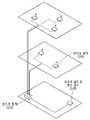
도 1은 본 발명의 일실시예에 따른 분산형 안테나 시스템(Distributed Antenna System, DAS)이 적용된 건물의 구조를 개념적으로 도시한 도면이다. 건물은 인간이 지은 지면에 고정되는 구조물을 의미한다. 건물의 예로써, 제조 공장, 오피스 빌딩, 주택, 아파트 등이 있다. 일실시예에 따른 호스트 장치(110)는 건물 내에 배치되고, 건물 내의 사용자에게 전달되는 무선 신호를 중계할 수 있다. 호스트 장치(110)는 무선 신호를 중계하기 위하여, 리모트 라디오 헤드 장치(120) 및 라디오 장치(120)와 연결될 수 있다. 리모트 라디오 헤드 장치(120)는 무선 서비스를 제공하는 무선 네트워크 사업자의 망 구축 방식 및 운용 방식에 따라 건물 외부 또는 건물 내부에 배치될 수 있다.1 is a diagram conceptually illustrating the structure of a building to which a Distributed Antenna System (DAS) according to an embodiment of the present invention is applied. A building is a structure built by humans and fixed to the ground. Examples of buildings include manufacturing plants, office buildings, houses, apartments, and the like. The
일실시예에 따른 라디오 장치(120)는 실내에 배치됨으로써, 무선 서비스를 실내의 사용자 단말에 제공할 수 있다. 도 1을 참고하면, 라디오 장치(120)는 무선 서비스를 실내의 사용자 단말에 제공하기 위하여, 적어도 하나의 안테나를 포함할 수 있다. 라디오 장치(120)는 10GHz 이상 300GHz 이하의 주파수로써, 그 파장의 길이가 1cm 이상 1mm 이하인 밀리미터파 대역의 무선 신호를 송수신할 수 있다.The radio device 120 according to an embodiment may be disposed indoors, thereby providing wireless services to user terminals indoors. Referring to FIG. 1 , the radio device 120 may include at least one antenna in order to provide a wireless service to an indoor user terminal. The radio device 120 may transmit/receive a millimeter wave band radio signal having a wavelength of 1 cm or more and 1 mm or less at a frequency of 10 GHz or more and 300 GHz or less.
라디오 장치(120)는 실내의 다양한 위치에 배치될 수 있다. 라디오 장치(120)는 층 별로 또는 방 별로 배치될 수 있다. 라디오 장치(120)의 위치는 실내의 음영 지역을 최소화하도록 결정될 수 있다. 전파가 건물 내에서 어떻게 전파되는지를 고려하여, 라디오 장치(120)의 위치가 결정될 수 있다.The radio device 120 may be placed in various locations in the room. The radio devices 120 may be arranged per floor or per room. The location of the radio device 120 may be determined to minimize a shaded area in the room. The location of the radio device 120 can be determined by considering how radio waves propagate within a building.
호스트 장치(110) 및 라디오 장치(120)는 광 케이블을 통해 연결될 수 있다. 호스트 장치(110) 및 라디오 장치(120)는 점대점 구성(Point-to-Point configuration) 또는 점대다점 구성(Point-to-Multi-Point configuration)에 따라 연결될 수 있다. 도 1은 호스트 장치(110)가 복수의 라디오 장치(120)들 각각과 점대점 구성으로 연결된 구조를 도시한다. 이는 예시에 불과하며, 호스트 장치(110) 및 복수의 라디오 장치(120)들이 광 스플리터 또는 광 멀티플렉서/디멀티플렉서를 이용하여, 점대다점 구성에 따라 연결될 수 있다. 호스트 장치(110) 및 라디오 장치(120) 간의 거리가 상대적으로 짧은 경우, 호스트 장치(110) 및 라디오 장치(120)는 동축케이블을 통해 연결될 수 있다.The
호스트 장치(110) 및 라디오 장치(120) 사이를 연결하는 광 케이블은 적어도 하나의 광 섬유를 포함할 수 있다. 광 케이블은 단일 모드 광섬유 또는 다중 모드 광섬유를 포함할 수 있다. 호스트 장치(110) 및 라디오 장치(120)는 아날로그 광 트랜시버를 사용하여 광 신호를 송 수신할 수 있다. 아날로그 광 트랜시버는 사용자 단말로 전달될 전기 신호를 전광 변환 또는 광전 변환할 수 있다. 더 나아가서, 아날로그 광 트랜시버는 아날로그 광 신호의 전송에 따른 왜곡을 최소화할 수 있다.An optical cable connecting between the
이하에서는 도 2 및 도 3을 참고하여 리모트 라디오 헤드 장치(120), 호스트 장치(110), 라디오 장치(120) 및 사용자 단말 사이의 네트워크 및 파장 대역을 보다 상세히 설명한다.Hereinafter, a network and a wavelength band between the remote radio head device 120, the
도 2는 본 발명의 일실시예에 따른 리모트 라디오 헤드 장치(220), 호스트 장치(210), 라디오 장치(230) 및 사용자 단말(240) 사이의 네트워크를 설명하기 위한 예시적인 도면이다.2 is an exemplary diagram for explaining a network between the remote
도 2를 참고하면, 리모트 라디오 헤드 장치(220) 및 호스트 장치(210)는 광 케이블을 이용하여 연결될 수 있다. 리모트 라디오 헤드 장치(220)는 프론트홀에 포함될 수 있다. 리모트 라디오 헤드 장치(220)는 기저 대역(baseband)의 디지털 광 신호를 호스트 장치(210)로 송신할 수 있다. 호스트 장치(210)는 기저 대역의 디지털 광 신호를 리모트 라디오 헤드 장치(220)로 전송할 수 있다. 리모트 라디오 장??(220) 및 호스트 장치(210) 사이의 연결은 디지털 광 신호를 사용하는 디지털 광 링크일 수 있다. 리모트 라디오 헤드 장치(220) 및 호스트 장치(210)는 디지털 광 신호를 송수신하기 위하여, SFP, SFP+, SFP-28 및 XFP등의 디지털 광 트랜시버를 포함할 수 있다.Referring to FIG. 2 , the remote
도 2를 참고하면, 호스트 장치(210) 및 라디오 장치(230)는 광 케이블을 이용하여 연결될 수 있다. 일실시예에 따른 호스트 장치(210)는 리모트 라디오 헤드 장치(220) 및 라디오 장치(230)를 중계할 수 있다. 호스트 장치(210)는 리모트 라디오 헤드 장치(220)로부터 수신한 디지털 광 신호를 아날로그 광 신호로 변환할 수 있다.Referring to FIG. 2 , the
호스트 장치(210) 및 라디오 장치(230)는 호스트 장치(210) 및 라디오 장치(230)의 광 전송을 지원하는 아날로그 광 트랜시버를 포함할 수 있다. 아날로그 광 트랜시버는 호스트 장치(210)가 생성한 아날로그 전기 신호를 아날로그 광 신호로 변환한 다음, 라디오 장치(230)로 전달할 수 있다. 아날로그 광 트랜시버는 다중화된 아날로그 광 신호를 생성할 수 있다.The
아날로그 광 신호의 중심 주파수는 DC에 근접한 10GHz 이하의 주파수 중에서 결정될 수 있다. 아날로그 광 신호의 중심 주파수가 10GHz 이하의 주파수 중에서 결정되므로, 아날로그 광 트랜시버는 직접 변조형 레이저 다이오드를 포함할 수 있다. 따라서, 호스트 장치(210) 및 라디오 장치(230)는 경제적으로 아날로그 광 전송을 수행할 수 있다.The center frequency of the analog optical signal may be determined among frequencies of 10 GHz or less close to DC. Since the center frequency of the analog optical signal is determined among frequencies below 10 GHz, the analog optical transceiver may include a direct modulated laser diode. Therefore, the
도 2를 참고하면, 라디오 장치(230) 및 사용자 단말(240)은 무선 신호를 송 수신할 수 있다. 라디오 장치(230)는 호스트 장치(210)로부터 수신한 아날로그 광 신호를 밀리미터파 대역의 아날로그 무선 신호로 변환한 다음, 변환된 아날로그 무선 신호를 사용자 단말(240)로 전달할 수 있다. 역으로, 라디오 장치(230)는 사용자 단말(240)로부터 수신한 아날로그 무선 신호를 아날로그 광 신호로 변환한 다음, 변환된 아날로그 광 신호를 호스트 장치(210)로 전달할 수 있다.Referring to FIG. 2 , the
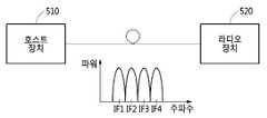
도 3은 본 발명의 일실시예에 따른 호스트 장치 및 라디오 장치가 사용하는 아날로그 광 신호의 파장 대역, 라디오 장치 및 사용자 단말이 사용하는 아날로그 무선 신호의 파장 대역을 설명하기 위한 도면이다.3 is a diagram for explaining a wavelength band of an analog optical signal used by a host device and a radio device, and a wavelength band of an analog radio signal used by a radio device and a user terminal according to an embodiment of the present invention.
도 3을 참고하면, 광 신호 대역(310)은 호스트 장치 및 라디오 장치의 아날로그 광 트랜시버가 생성한 아날로그 광 신호의 대역을 의미한다. 즉, 호스트 장치 및 라디오 장치는 광 신호 대역(310)의 아날로그 광 신호를 송수신할 수 있다. 도 3을 참고하면, 광 신호 대역(310)은 하나 이상의 중간 주파수(IF1, IF2 내지 IFN)를 포함할 수 있다. 광 신호 대역(310)이 복수의 중간 주파수를 포함하는 경우, 아날로그 광 신호의 주파수는 복수의 중간 주파수들 중 어느 하나로 선택될 수 있다.Referring to FIG. 3 , an optical signal band 310 means a band of an analog optical signal generated by an analog optical transceiver of a host device and a radio device. That is, the host device and the radio device may transmit and receive analog optical signals of the optical signal band 310 . Referring to FIG. 3 , the optical signal band 310 may include one or more intermediate frequencies IF1, IF2 to IFN. When the optical signal band 310 includes a plurality of intermediate frequencies, the frequency of the analog optical signal may be selected as one of the plurality of intermediate frequencies.
일실시예에 따르면, 호스트 장치 및 라디오 장치는 서로 다른 중간 주파수를 가지는 복수의 광 신호들이 다중화된 아날로그 광 신호를 송 수신할 수 있다. FA (frequency assignment) 신호는 복수의 광 신호들이 다중화된 아날로그 광 신호를 의미한다. 도 3을 참고하면, 아날로그 광 트랜시버는 주파수가 IF1, IF2 내지 IFN인 광 신호들을 다중화함으로써, FA 신호를 생성할 수 있다.According to an embodiment, the host device and the radio device may transmit and receive analog optical signals in which a plurality of optical signals having different intermediate frequencies are multiplexed. A frequency assignment (FA) signal refers to an analog optical signal in which a plurality of optical signals are multiplexed. Referring to FIG. 3 , the analog optical transceiver may generate an FA signal by multiplexing optical signals having frequencies of IF1, IF2 to IFN.
도 3을 참고하면, 무선 신호 대역(320)은 라디오 장치 및 사용자 단말이 사용하는 아날로그 무선 신호의 대역을 의미한다. 무선 신호 대역(320)은 밀리미터파 대역에 포함될 수 있다. 무선 신호 대역(320)은 하나 이상의 밀리미터파 대역의 중심 주파수(MMW1, MMW2 내지 MMWN)을 포함할 수 있다. 도 3을 참고하면, 무선 신호 대역(320)의 주파수는 광 신호 대역(310) 보다 클 수 있다. 예를 들어, 광 신호 대역(310)의 주파수는 10GHz 미만일 수 있으며, 무선 신호 대역(320)의 주파수는 10GHz 이상일 수 있다.Referring to FIG. 3 , a radio signal band 320 means a band of an analog radio signal used by a radio device and a user terminal. The wireless signal band 320 may be included in the millimeter wave band. The radio signal band 320 may include center frequencies MMW1, MMW2 to MMWN of one or more millimeter wave bands. Referring to FIG. 3 , the frequency of the radio signal band 320 may be higher than that of the optical signal band 310 . For example, the frequency of the optical signal band 310 may be less than 10 GHz, and the frequency of the wireless signal band 320 may be greater than 10 GHz.
일실시예에 따른 라디오 장치는 광 신호 대역(310)의 아날로그 광 신호를 무선 신호 대역(320)의 아날로그 무선 신호로 변경할 수 있다(주파수 상향 변환). 라디오 장치는 변경된 아날로그 무선 신호를 사용자 단말로 전송할 수 있다.A radio device according to an embodiment may change an analog optical signal of an optical signal band 310 into an analog radio signal of a radio signal band 320 (frequency upconversion). The radio device may transmit the changed analog radio signal to the user terminal.
반대로, 라디오 장치는 무선 신호 대역(320)의 아날로그 무선 신호를 사용자 단말로부터 수신할 수 있다. 라디오 장치는 수신한 아날로그 무선 신호로부터, 광 신호 대역(310)의 아날로그 광 신호를 생성할 수 있다(주파수 하향 변환). 라디오 장치는 생성된 아날로그 광 신호를 라디오 장치로 전송할 수 있다.Conversely, the radio device may receive an analog radio signal of the radio signal band 320 from the user terminal. The radio device may generate an analog optical signal of the optical signal band 310 from the received analog radio signal (frequency down-conversion). The radio device may transmit the generated analog optical signal to the radio device.
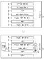
도 4는 본 발명의 일실시예에 따른 호스트 장치(410) 및 라디오 장치(420)의 구조를 개념적으로 도시한 도면이다. 이하에서는 호스트 장치(410) 및 라디오 장치(420)의 구조가 기지국에서 사용자 단말로 향하는 다운 링크를 따라 설명된다.FIG. 4 conceptually illustrates structures of a
기지국에서 생성된 디지털 광 신호는 프론트홀을 구성하는 리모트 라디오 헤드 장치를 통과하여 호스트 장치(410)로 전달될 수 있다. 호스트 장치(410)는 라디오 장치(420)가 배치된 건물의 실내에 배치될 수 있다. 리모트 라디오 헤드 장치 및 호스트 장치(410)는 디지털 광 트랜시버(411)를 이용하여 디지털 광 신호를 송 수신할 수 있다. 리모트 라디오 헤드 장치 및 호스트 장치(410)는 대용량의 데이터를 전송할 수 있는 광 케이블로 연결될 수 있다.The digital optical signal generated by the base station may be transferred to the
도 4를 참고하면, 일실시예에 따른 호스트 장치(410)는 다운 링크를 통해 수신한 디지털 광 신호를 디지털 전기 신호로 변경하는 디지털 광 트랜시버(411)를 포함할 수 있다. 디지털 광 트랜시버(411)에 의해 변경된 디지털 전기 신호는 복수의 프레임을 포함할 수 있다.Referring to FIG. 4 , the
도 4를 참고하면, 일실시예에 따른 호스트 장치(410)는 디지털 광 트랜시버(411)가 변경한 디지털 전기 신호를 디프레이밍(deframing)하여, 기저 대역의 디지털 전기 신호를 생성하는 디지털 신호 처리기(412)를 포함할 수 있다. 디프레이밍은 디지털 전기 신호에 포함된 프레임의 헤더 부분 및 페이로드 부분을 분할하는 것을 의미한다. 예를 들어, 디지털 신호 처리기(412)는 디지털 전기 신호에 포함된 프레임을 2바이트 길이의 헤더 부분 및 4바이트 길이의 페이로드 부분으로 분할할 수 있다. 즉, 디지털 전기 신호의 프레임의 길이는 6바이트일 수 있다. 디지털 신호 처리기(412)는 디지털 전기 신호에 포함된 복수의 프레임에 대하여 디프레이밍을 수행할 수 있다. 디지털 신호 처리기(412)는 다양한 디지털 신호 처리를 수행할 수 있다. 디지털 신호 처리기(412)는 기저 대역의 디지털 전기 신호를 생성할 수 있다.Referring to FIG. 4 , the
도 4를 참고하면, 호스트 장치(410)에 복수의 라디오 장치가 연결된 경우, 일실시예에 따른 호스트 장치(410)는 기저 대역의 디지털 전기 신호를, 복수의 라디오 장치들 중 어디로 송신할지에 따라 분류하는 스위치(413)를 포함할 수 있다. 디지털 전기 신호는 서로 다른 라디오 장치로 향하는 복수의 데이터들을 포함할 수 있다. 스위치(413)는 복수의 데이터들 각각을 전송할 라디오 장치에 따라, 디지털 전기 신호에 포함된 데이터들을 분류할 수 있다. 바꾸어 말하면, 디지털 전기 신호에 포함된 복수의 데이터들은 전송되어야 하는 라디오 장치 별로 배치될 수 있다.Referring to FIG. 4 , when a plurality of radio devices are connected to the
도 4를 참고하면, 일실시예에 따른 호스트 장치(410)는 기저 대역의 디지털 전기 신호를 아날로그 전기 신호로 변경하는 디지털-아날로그 변환기(414)를 포함할 수 있다. 호스트 장치(410)에 복수의 라디오 장치가 연결된 경우, 디지털-아날로그 변환기(414)는 스위치(413)에 의해 복수의 라디오 장치 별로 분류된 기저 대역의 디지털 전기 신호를 수신할 수 있다. 디지털-아날로그 변환기(414)가 생성한 아날로그 전기 신호의 주파수는 중간 주파수와 동일할 수 있다.Referring to FIG. 4 , the
도 4를 참고하면, 일실시예에 따른 호스트 장치(410)는 아날로그 전기 신호의 크기(amplitude)를 조절하는 아날로그 프론트 엔드 제어기(415)를 포함할 수 있다. 아날로그 프론트 엔드 제어기(415)는 아날로그 전기 신호를 성형할 수 있다. 보다 구체적으로, 아날로그 프론트 엔드 제어기(415)는 아날로그 전기 신호의 파형의 크기를 변경할 수 있다. 특히, 아날로그 프론트 엔드 제어기(415)는 호스트 장치(410) 및 라디오 장치(420) 간의 광 전송을 고려하여 아날로그 전기 신호를 성형할 수 있다. 따라서, 아날로그 프론트 엔드 제어기(415)를 통과한 아날로그 전기 신호는 아날로그 광 전송에 적합한 크기를 가질 수 있다. 아날로그 프론트 엔드 제어기(415)는 아날로그 전기 신호의 크기를 조절하는 증폭기 또는 감쇄기를 포함할 수 있다.Referring to FIG. 4 , a
도 4를 참고하면, 일실시예에 따른 호스트 장치(410)는 조절된 아날로그 전기 신호에 주파수 동기 신호, 시분할 이중 통신(Time Division Duplex) 신호 또는 라디오 장치(420)에 대한 제어 신호 중 적어도 하나를 결합하는 결합기(416)를 포함할 수 있다. 호스트 장치(410)는 라디오 장치(420)가 아날로그 무선 신호를 생성하는 데 필요한 주파수 동기 신호 또는 시분할 이중 통신 신호를 생성할 수 있다. 호스트 장치(410)는 제어 신호를 이용하여 라디오 장치(420)를 제어하거나, 또는 라디오 장치(420)를 감시할 수 있다.Referring to FIG. 4 , the
도 4를 참고하면, 일실시예에 따른 호스트 장치(410)는 결합기(416)에 의해 결합된 아날로그 전기 신호를 아날로그 광 신호로 변경하는 아날로그 광 트랜시버(417)를 포함할 수 있다. 호스트 장치(410)는 아날로그 광 트랜시버(417)에 의해 생성된 아날로그 광 신호를 라디오 장치(420)로 송신할 수 있다.Referring to FIG. 4 , the
아날로그 광 트랜시버(417)는 아날로그 전기 신호를 아날로그 광 신호로 직접 변조하는 직접 변조형 레이저 다이오드를 포함할 수 있다. 직접 변조형 레이저 다이오드를 사용함으로써, 아날로그 광 트랜시버(417)의 비용이 절감될 수 있다.The analog
도 4를 참고하면, 호스트 장치(410)가 생성한 아날로그 광 신호는 광 케이블을 통과하여 라디오 장치(420)의 아날로그 광 트랜시버(421)로 전달될 수 있다. 아날로그 광 트랜시버(421)는 수신한 아날로그 광 신호를 아날로그 전기 신호로 변경할 수 있다.Referring to FIG. 4 , an analog optical signal generated by the
도 4를 참고하면, 라디오 장치(420)는 아날로그 전기 신호로부터 주파수 동기 신호, 시분할 이중 통신(Time Division Duplex, TDD) 신호 또는 라디오 장치(420)에 대한 제어 신호 중 적어도 하나를 분리하는 분리기(422)를 포함할 수 있다. 분리기(422)는 주파수 동기 신호, TDD 신호 및 제어 신호를 각각의 용도에 따라 분배할 수 있다. 분리기(422)는 아날로그 전기 신호로부터 분리한 주파수 동기 신호를 주파수 동기부(427)로 전달할 수 있다. 분리기(422)는 아날로그 전기 신호로부터 분리한 TDD 신호를 TDD 컨트롤러(428)로 전달할 수 있다. 분리기(422)는 제어 신호를 라디오 장치(420)의 컨트롤러에 전달할 수 있다.Referring to FIG. 4 , the
도 4를 참고하면, 라디오 장치(420)는 사용자 단말로의 무선 전송을 고려하여 분리된 아날로그 전기 신호의 크기를 조절하는 아날로그 프론트 엔드 제어기(423)를 포함할 수 있다. 아날로그 프론트 엔드 제어기(423)는 아날로그 전기 신호의 주파수를 기저 대역에서 밀리미터파 대역으로 변환하는 과정을 고려하여, 아날로그 전기 신호의 크기를 변경할 수 있다. 아날로그 프론트 엔드 제어기(423)는 아날로그 전기 신호를 성형할 수 있다. 즉, 아날로그 전기 신호의 크기는 아날로그 광 신호로의 변환에 적합하도록 조절될 수 있다.Referring to FIG. 4 , the
도 4를 참고하면, 라디오 장치(420)는 조절된 아날로그 전기 신호의 주파수를 라디오 장치(420) 및 상기 사용자 단말간의 무선 전송에 사용되는 무선 주파수로 변환하는 주파수 변환기(424)를 포함할 수 있다. 주파수 변환기(424)는 중간 주파수를 가지는 아날로그 전기 신호를, 밀리미터파 대역의 주파수를 가지는 아날로그 전기 신호로 변경할 수 있다. 도 4를 참고하면, 주파수 변환기(424)는 주파수 동기부(427)의 제어 신호에 따라 아날로그 전기 신호의 주파수를 변경할 수 있다.Referring to FIG. 4 , the
앞서 설명한 바와 같이, 밀리미터파 대역의 주파수는 중간 주파수보다 크므로, 주파수 변환기(424)는 아날로그 전기 신호를 주파수 상향 변환할 수 있다. 주파수 변환기(424)가 변경한 아날로그 전기 신호의 주파수는 사용자 단말이 사용하는 아날로그 무선 신호의 주파수와 동일할 수 있다.As described above, since the frequency of the millimeter wave band is higher than the intermediate frequency, the
도 4를 참고하면, 주파수 변환기(424)가 변환한 아날로그 전기 신호는 증폭기(425) 및 안테나(426)를 통과함으로써, 아날로그 무선 신호로 변경될 수 있다. 증폭기(425)는 아날로그 무선 신호의 크기를 고려하여, 아날로그 전기 신호의 크기를 변경할 수 있다. 안테나(426)는 아날로그 전기 신호를 아날로그 무선 신호로 변경할 수 있다. 안테나(426)는 아날로그 무선 신호를 사용자 단말로 송신할 수 있다. 아날로그 무선 신호의 주파수는 밀리미터파 대역에 포함될 수 있다.Referring to FIG. 4 , the analog electrical signal converted by the
호스트 장치(410) 및 라디오 장치(420)는 사용자 단말에서 기지국으로 향하는 업 링크에 대해서도, 다운 링크에서 설명한 바와 유사하게 작동할 수 있다.The
도 4를 참고하면, 사용자 단말은 밀리미터파 대역의 아날로그 무선 신호를 안테나(426)로 전달할 수 있다. 안테나(426)는 수신한 아날로그 무선 신호를 아날로그 전기 신호로 변환하여 증폭기(425)로 전달할 수 있다. 아날로그 전기 신호는 증폭기(425)를 통과한 다음, 주파수 변환기(424)로 전달될 수 있다. 주파수 변환기(424)는 아날로그 전기 신호의 주파수를 밀리미터파 대역의 주파수에서 중간 주파수로 변경할 수 있다. 밀리미터파 대역의 주파수는 중간 주파수보다 크므로, 주파수 변환기(424)는 아날로그 전기 신호를 주파수 하향 변환할 수 있다.Referring to FIG. 4 , a user terminal may transmit an analog radio signal of a millimeter wave band to an
주파수 하향 변환된 아날로그 전기 신호는 아날로그 프론트 엔드 제어기(423)에 의해 성형될 수 있다. 즉, 아날로그 프론트 엔드 제어기(423)는 호스트 장치(410)로의 광 전송을 고려하여, 아날로그 전기 신호의 파형을 조절할 수 있다. 아날로그 프론트 엔드 제어기(423)를 통과한 아날로그 전기 신호는 아날로그 광 트랜시버(421)에 의해 아날로그 광 신호로 변환될 수 있다. 복수의 사용자 단말들이 라디오 장치(420)에 연결된 경우, 아날로그 프론트 엔드 제어기(423)를 통과한 복수의 사용자 단말들 각각의 아날로그 전기 신호는 분리기(423)에 의해 하나의 경로로 결합될 수 있다. 이 경우, 아날로그 광 트랜시버(421)는 결합된 아날로그 전기 신호를 아날로그 광 신호로 변환할 수 있다. 변환된 아날로그 광 신호는 광 케이블을 따라 호스트 장치(410)의 아날로그 광 트랜시버(417)로 전달될 수 있다.The frequency down-converted analog electrical signal may be shaped by the analog
호스트 장치(410)의 아날로그 광 트랜시버(417)는 수신한 아날로그 광 신호를 아날로그 전기 신호로 변경할 수 있다. 변경된 아날로그 전기 신호는 아날로그 프론트 엔드 제어기(415)에 의해 성형될 수 있다. 아날로그 프론트 엔드 제어기(415)는 리모트 라디오 헤드 장치로의 디지털 광 전송을 고려하여, 아날로그 전기 신호의 파형을 변경할 수 있다. 변경된 아날로그 전기 신호는 디지털-아날로그 변환기(414)에 의해 디지털 전기 신호로 변경될 수 있다. 복수의 라디오 장치들이 호스트 장치(410)에 연결된 경우, 복수의 라디오 장치들 각각의 디지털 전기 신호들은 스위치(413)에 의해 하나의 경로로 결합될 수 있다.The analog
디지털 신호 처리기(412)는 결합된 디지털 전기 신호를 수신할 수 있다. 디지털 신호 처리기(412)는 디지털 전기 신호를, 호스트 장치(410) 및 기저 대역 장치 간의 광 전송을 고려하여 디지털 프레이밍(framing)할 수 있다. 즉, 디지털 신호 처리기(412)는 헤더 부분 및 페이로드 부분을 결합하여 디지털 프레임을 생성할 수 있다. 디지털 광 트랜시버(411)는 디지털 신호 처리기(412)를 통과한 디지털 전기 신호를 디지털 광 신호로 변경하여 리모트 라디오 헤드 장치로 전송할 수 있다.
앞서 설명한 바와 같이, 호스트 장치(410) 및 라디오 장치(420)는 디지털 샘플링을 하지 않고 데이터를 전송할 수 있다. 디지털 샘플링을 하지 않으므로, 무선 신호를 전송하는데 요구되는 데이터 트래픽의 양은 기저 대역의 대역폭과 일치할 수 있다. 따라서, 망 구축 및 운용 비용이 절감될 수 있다. 더 나아가서, 호스트 장치(410) 및 라디오 장치(420)는 디지털 샘플링 및 프레이밍을 수행하지 않으므로, 디지털 송수신하는 것에 비해 딜레이가 짧을 수 있다.As described above, the
이하에서는 호스트 장치(410) 및 라디오 장치(420)가 어떻게 연결되는지에 따라 기저 대역에 포함된 중간 주파수들이 어떻게 활용되는지를 설명한다.Hereinafter, how the intermediate frequencies included in the baseband are utilized according to how the
도 5는 본 발명의 일실시예에 따른 호스트 장치(510) 및 라디오 장치(520)가 점대점 구성으로 연결된 네트워크의 구조의 예시적인 도면이다.5 is an exemplary diagram of a structure of a network in which a
호스트 장치(510) 및 라디오 장치(520)는 업 링크 및 다운 링크 각각에 대하여 서로 다른 파장을 이용할 수 있다. 점대점 구성에서, 호스트 장치(510)가 생성한 아날로그 광 신호는 하나의 라디오 장치(520)로 송신될 수 있다. 즉, 복수의 사용자 단말들은 하나의 라디오 장치(520)를 통해 호스트 장치(510)와 연결될 수 있다. 복수의 사용자 단말들 각각이 생성한 아날로그 무선 신호들은 라디오 장치(520)에 의해 하나의 아날로그 광 신호로 결합될 수 있다.The
호스트 장치(510) 및 라디오 장치(520)는 주파수 분할 다중화(Wavelength Division Multiplexing, WDM) 방식을 이용하여 아날로그 광 신호를 송수신할 수 있다. 도 5를 참고하면, 기저 대역은 하나 이상의 중간 주파수(IF1, IF2 내지 IFN)를 포함할 수 있다. 호스트 장치(510)는 서로 다른 중간 주파수를 가지는 광 신호를 다중화한 아날로그 광 신호를 라디오 장치(520)로 송신할 수 있다. 라디오 장치(520)는 서로 다른 중간 주파수를 가지는 광 신호를 다중화한 아날로그 광 신호를 호스트 장치(510)로 송신할 수 있다.The
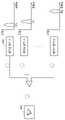
도 6은 본 발명의 일실시예에 따른 호스트 장치(610) 및 라디오 장치(620)가 점대다점 구성으로 연결된 네트워크의 구조의 예시적인 도면이다. 도 6을 참고하면, 하나의 호스트 장치(610)에 복수의 라디오 장치(620)들이 연결될 수 있다. 호스트 장치(610) 및 라디오 장치(620) 사이의 다운 링크에 대하여, 호스트 장치(610)는 파장 분할 다중화 방식 또는 주파수 분할 다중화 방식에 따라 아날로그 광 신호를 송신할 수 있다. 호스트 장치(610) 및 라디오 장치(620) 사이의 업 링크에서, 라디오 장치(620)는 단일 파장을 사용할 때 발생되는 광 비팅 잡음(Optical beating interference)을 고려하여, 파장 분할 다중화 방식에 따라 아날로그 광 신호를 송신할 수 있다.6 is an exemplary diagram of a structure of a network in which a
다운 링크에서, 호스트 장치(610)가 생성한 아날로그 광 신호는 주파수 영역에서 분할된 다음, 분할된 주파수에 따라 서로 다른 라디오 장치(620)로 전달될 수 있다. 도 6을 참고하면, 호스트 장치(610)에 연결된 복수의 라디오 장치(620)들은 서로 다른 중간 주파수를 사용할 수 있다. 호스트 장치(610)가 생성한 아날로그 광 신호는 복수의 중간 주파수들을 따라 분할될 수 있다. 분할된 아날로그 광 신호들은 대응하는 중간 주파수를 사용하는 라디오 장치(620)로 전달될 수 있다.In the downlink, the analog optical signal generated by the
업 링크에서, 복수의 라디오 장치(620)들은 서로 다른 중간 주파수를 가지는 아날로그 광 신호를 생성할 수 있다. 즉, 사용자 단말이 생성한 밀리미터파 대역의 아날로그 무선 신호는 사용자 단말이 가입한 라디오 장치(620)가 사용하는 중간 주파수를 가지는 아날로그 광 신호로 변환될 수 있다. 복수의 라디오 장치(620)들이 생성한 복수의 아날로그 광 신호들은 다중화되어 호스트 장치(610)로 전달될 수 있다. 호스트 장치(610)는 수신한 아날로그 광 신호를 디지털 광 신호로 변경한 다음, 리모트 라디오 헤드 장치로 송신할 수 있다.In the uplink, a plurality of
실시예들에서 설명된 구성요소들은 하나 이상의 DSP (Digital Signal Processor), 프로세서 (Processor), 컨트롤러 (Controller), ASIC (Application Specific Integrated Circuit), FPGA (Field Programmable Gate Array)와 같은 프로그래머블 논리 소자 (Programmable Logic Element), 다른 전자 기기들 및 이것들의 조합 중 하나 이상을 포함하는 하드웨어 구성 요소들(hardware components)에 의해 구현될 수 있다. 실시예들에서 설명된 기능들(functions) 또는 프로세스들(processes) 중 적어도 일부는 소프트웨어(software)에 의해 구현될 수 있고, 해당 소프트웨어는 기록 매체(recording medium)에 기록될 수 있다. 실시예들에서 설명된 구성요소들, 기능들 및 프로세스들은 하드웨어와 소프트웨어의 조합에 의해 구현될 수 있다.The components described in the embodiments are programmable logic devices such as one or more digital signal processors (DSPs), processors, controllers, application specific integrated circuits (ASICs), and field programmable gate arrays (FPGAs). Logic Element), other electronic devices, and hardware components including one or more combinations thereof. At least some of the functions or processes described in the embodiments may be implemented by software, and the software may be recorded on a recording medium. Components, functions, and processes described in the embodiments may be implemented by a combination of hardware and software.
이상에서 설명된 장치는 하드웨어 구성요소, 소프트웨어 구성요소, 및/또는 하드웨어 구성요소 및 소프트웨어 구성요소의 조합으로 구현될 수 있다. 예를 들어, 실시예들에서 설명된 장치 및 구성요소는, 예를 들어, 프로세서, 콘트롤러, ALU(arithmetic logic unit), 디지털 신호 프로세서(digital signal processor), 마이크로컴퓨터, FPGA(field programmable gate array), PLU(programmable logic unit), 마이크로프로세서, 또는 명령(instruction)을 실행하고 응답할 수 있는 다른 어떠한 장치와 같이, 하나 이상의 범용 컴퓨터 또는 특수 목적 컴퓨터를 이용하여 구현될 수 있다. 처리 장치는 운영 체제(OS) 및 상기 운영 체제 상에서 수행되는 하나 이상의 소프트웨어 애플리케이션을 수행할 수 있다. 또한, 처리 장치는 소프트웨어의 실행에 응답하여, 데이터를 접근, 저장, 조작, 처리 및 생성할 수도 있다. 이해의 편의를 위하여, 처리 장치는 하나가 사용되는 것으로 설명된 경우도 있지만, 해당 기술분야에서 통상의 지식을 가진 자는, 처리 장치가 복수 개의 처리 요소(processing element) 및/또는 복수 유형의 처리 요소를 포함할 수 있음을 알 수 있다. 예를 들어, 처리 장치는 복수 개의 프로세서 또는 하나의 프로세서 및 하나의 콘트롤러를 포함할 수 있다. 또한, 병렬 프로세서(parallel processor)와 같은, 다른 처리 구성(processing configuration)도 가능하다.The devices described above may be implemented as hardware components, software components, and/or a combination of hardware components and software components. For example, devices and components described in the embodiments may include, for example, a processor, a controller, an arithmetic logic unit (ALU), a digital signal processor, a microcomputer, a field programmable gate array (FPGA) , a programmable logic unit (PLU), microprocessor, or any other device capable of executing and responding to instructions. A processing device may run an operating system (OS) and one or more software applications running on the operating system. A processing device may also access, store, manipulate, process, and generate data in response to execution of software. For convenience of understanding, there are cases in which one processing device is used, but those skilled in the art will understand that the processing device includes a plurality of processing elements and/or a plurality of types of processing elements. It can be seen that it can include. For example, a processing device may include a plurality of processors or a processor and a controller. Other processing configurations are also possible, such as parallel processors.
소프트웨어는 컴퓨터 프로그램(computer program), 코드(code), 명령(instruction), 또는 이들 중 하나 이상의 조합을 포함할 수 있으며, 원하는 대로 동작하도록 처리 장치를 구성하거나 독립적으로 또는 결합적으로(collectively) 처리 장치를 명령할 수 있다. 소프트웨어 및/또는 데이터는, 처리 장치에 의하여 해석되거나 처리 장치에 명령 또는 데이터를 제공하기 위하여, 어떤 유형의 기계, 구성요소(component), 물리적 장치, 가상 장치(virtual equipment), 컴퓨터 저장 매체 또는 장치, 또는 전송되는 신호 파(signal wave)에 영구적으로, 또는 일시적으로 구체화(embody)될 수 있다. 소프트웨어는 네트워크로 연결된 컴퓨터 시스템 상에 분산되어서, 분산된 방법으로 저장되거나 실행될 수도 있다. 소프트웨어 및 데이터는 하나 이상의 컴퓨터 판독 가능 기록 매체에 저장될 수 있다.Software may include a computer program, code, instructions, or a combination of one or more of the foregoing, which configures a processing device to operate as desired or processes independently or collectively. The device can be commanded. Software and/or data may be any tangible machine, component, physical device, virtual equipment, computer storage medium or device, intended to be interpreted by or provide instructions or data to a processing device. , or may be permanently or temporarily embodied in a transmitted signal wave. Software may be distributed on networked computer systems and stored or executed in a distributed manner. Software and data may be stored on one or more computer readable media.
실시예에 따른 방법은 다양한 컴퓨터 수단을 통하여 수행될 수 있는 프로그램 명령 형태로 구현되어 컴퓨터 판독 가능 매체에 기록될 수 있다. 상기 컴퓨터 판독 가능 매체는 프로그램 명령, 데이터 파일, 데이터 구조 등을 단독으로 또는 조합하여 포함할 수 있다. 상기 매체에 기록되는 프로그램 명령은 실시예를 위하여 특별히 설계되고 구성된 것들이거나 컴퓨터 소프트웨어 당업자에게 공지되어 사용 가능한 것일 수도 있다. 컴퓨터 판독 가능 기록 매체의 예에는 하드 디스크, 플로피 디스크 및 자기 테이프와 같은 자기 매체(magnetic media), CD-ROM, DVD와 같은 광기록 매체(optical media), 플롭티컬 디스크(floptical disk)와 같은 자기-광 매체(magneto-optical media), 및 롬(ROM), 램(RAM), 플래시 메모리 등과 같은 프로그램 명령을 저장하고 수행하도록 특별히 구성된 하드웨어 장치가 포함된다. 프로그램 명령의 예에는 컴파일러에 의해 만들어지는 것과 같은 기계어 코드뿐만 아니라 인터프리터 등을 사용해서 컴퓨터에 의해서 실행될 수 있는 고급 언어 코드를 포함한다. 상기된 하드웨어 장치는 실시예의 동작을 수행하기 위해 하나 이상의 소프트웨어 모듈로서 작동하도록 구성될 수 있으며, 그 역도 마찬가지이다.The method according to the embodiment may be implemented in the form of program instructions that can be executed through various computer means and recorded on a computer readable medium. The computer readable medium may include program instructions, data files, data structures, etc. alone or in combination. Program commands recorded on the medium may be specially designed and configured for the embodiment or may be known and usable to those skilled in computer software. Examples of computer-readable recording media include magnetic media such as hard disks, floppy disks and magnetic tapes, optical media such as CD-ROMs and DVDs, and magnetic media such as floptical disks. - includes hardware devices specially configured to store and execute program instructions, such as magneto-optical media, and ROM, RAM, flash memory, and the like. Examples of program instructions include high-level language codes that can be executed by a computer using an interpreter, as well as machine language codes such as those produced by a compiler. The hardware devices described above may be configured to operate as one or more software modules to perform the operations of the embodiments, and vice versa.
이상과 같이 실시예들이 비록 한정된 실시예와 도면에 의해 설명되었으나, 해당 기술분야에서 통상의 지식을 가진 자라면 상기의 기재로부터 다양한 수정 및 변형이 가능하다. 예를 들어, 설명된 기술들이 설명된 방법과 다른 순서로 수행되거나, 및/또는 설명된 시스템, 구조, 장치, 회로 등의 구성요소들이 설명된 방법과 다른 형태로 결합 또는 조합되거나, 다른 구성요소 또는 균등물에 의하여 대치되거나 치환되더라도 적절한 결과가 달성될 수 있다.As described above, although the embodiments have been described with limited examples and drawings, those skilled in the art can make various modifications and variations from the above description. For example, the described techniques may be performed in an order different from the method described, and/or components of the described system, structure, device, circuit, etc. may be combined or combined in a different form than the method described, or other components may be used. Or even if it is replaced or substituted by equivalents, appropriate results can be achieved.
그러므로, 다른 구현들, 다른 실시예들 및 특허청구범위와 균등한 것들도 후술하는 특허청구범위의 범위에 속한다.Therefore, other implementations, other embodiments, and equivalents of the claims are within the scope of the following claims.
110: 호스트 장치
120: 라디오 장치
130: 리모트 라디오 헤드 장치110: host device
120: radio device
130: remote radio head device
Claims (11)
Translated fromKorean상기 리모트 라디오 헤드 장치에서 상기 호스트 장치로의 다운 링크를 통해 수신한 디지털 광 신호를 디지털 전기 신호로 변경하는 디지털 광 트랜시버;
상기 변경된 디지털 전기 신호를 디프레이밍하여, 기저 대역의 디지털 전기 신호를 생성하는 디지털 신호 처리기;
상기 기저 대역의 디지털 전기 신호를 아날로그 전기 신호로 변경하는 디지털-아날로그 변환기;
상기 호스트 장치 및 상기 라디오 장치간의 광 전송을 고려하여 상기 아날로그 전기 신호의 크기를 조절하는 아날로그 프론트 엔드 제어기;
상기 조절된 아날로그 전기 신호에 주파수 동기 신호, 시분할 이중 통신(Time Division Duplex) 신호 또는 상기 라디오 장치에 대한 제어 신호 중 적어도 하나를 결합하는 결합기;
상기 호스트 장치에서 상기 라디오 장치로의 다운 링크를 통해 상기 결합된 아날로그 전기 신호를 송신하기 위하여, 상기 결합된 아날로그 전기 신호를 아날로그 광 신호로 변경하는 아날로그 광 트랜시버
를 포함하는 호스트 장치.In a remote radio head device and a host device connected to the radio device,
a digital optical transceiver converting a digital optical signal received through a downlink from the remote radio head device to the host device into a digital electrical signal;
a digital signal processor deframing the changed digital electrical signal to generate a baseband digital electrical signal;
a digital-to-analog converter that converts the baseband digital electrical signal into an analog electrical signal;
an analog front end controller adjusting the level of the analog electric signal in consideration of optical transmission between the host device and the radio device;
a combiner for coupling at least one of a frequency synchronization signal, a time division duplex signal, and a control signal for the radio device to the conditioned analog electrical signal;
An analog optical transceiver converting the coupled analog electrical signal into an analog optical signal for transmitting the coupled analog electrical signal through a downlink from the host device to the radio device.
A host device comprising a.
상기 리모트 라디오 헤드 장치 및 상기 호스트 장치간의 다운 링크는 디지털 광 신호를 사용하는 디지털 광 링크인 호스트 장치.According to claim 1,
The downlink between the remote radio head device and the host device is a digital optical link using a digital optical signal.
상기 호스트 장치에 복수의 라디오 장치가 연결된 경우, 상기 기저 대역의 디지털 전기 신호를, 상기 복수의 라디오 장치들 중 어디로 송신할지에 따라 분류하는 스위치
를 더 포함하고,
상기 디지털-아날로그 변환기는,
상기 스위치에 의해 상기 복수의 라디오 장치 별로 분류된 상기 기저 대역의 디지털 전기 신호를 수신하는 호스트 장치.According to claim 1,
When a plurality of radio devices are connected to the host device, a switch that classifies the baseband digital electrical signal according to which one of the plurality of radio devices is to be transmitted.
Including more,
The digital-to-analog converter,
A host device configured to receive the baseband digital electrical signals classified for each of the plurality of radio devices by the switch.
상기 아날로그 프론트 엔드 제어기는,
상기 아날로그 전기 신호의 크기를 조절하는 증폭기 또는 감쇄기를 포함하는 호스트 장치.According to claim 1,
The analog front-end controller,
A host device including an amplifier or an attenuator for adjusting the level of the analog electrical signal.
상기 아날로그 광 트랜시버는,
중간 주파수를 고려하여 상기 아날로그 전기 신호를 상기 아날로그 광 신호로 직접 변조하는 레이저 다이오드
를 포함하는 호스트 장치.According to claim 1,
The analog optical transceiver,
A laser diode that directly modulates the analog electrical signal into the analog optical signal in consideration of the intermediate frequency
A host device comprising a.
상기 호스트 장치는, 실내(indoor)에 배치되는 호스트 장치.According to claim 1,
The host device is disposed indoors.
호스트 장치에서 라디오 장치로의 다운 링크를 통해 수신한 아날로그 광 신호를 아날로그 전기 신호로 변경하는 아날로그 광 트랜시버;
상기 아날로그 전기 신호로부터 주파수 동기 신호, 시분할 이중 통신(Time Division Duplex) 신호 또는 상기 라디오 장치에 대한 제어 신호 중 적어도 하나를 분리하는 분리기;
상기 라디오 장치 및 상기 사용자 단말간의 무선 전송을 고려하여 상기 분리된 아날로그 전기 신호의 크기를 조절하는 아날로그 프론트 엔드 제어기;
상기 조절된 아날로그 전기 신호의 주파수를 상기 라디오 장치 및 상기 사용자 단말간의 무선 전송에 사용되는 무선 주파수로 변환하는 주파수 변환기; 및
상기 무선 주파수로 변환된 아날로그 전기 신호를 아날로그 무선 신호로 변환하여 상기 사용자 단말로 송신하는 안테나
를 포함하는 라디오 장치.In a radio device wirelessly connected to a user terminal,
an analog optical transceiver that converts an analog optical signal received through a downlink from a host device to a radio device into an analog electrical signal;
a separator separating at least one of a frequency synchronization signal, a time division duplex signal, and a control signal for the radio device from the analog electrical signal;
an analog front-end controller adjusting the level of the separated analog electrical signal in consideration of wireless transmission between the radio device and the user terminal;
a frequency converter for converting the frequency of the adjusted analog electrical signal into a radio frequency used for wireless transmission between the radio device and the user terminal; and
An antenna that converts the analog electrical signal converted to the radio frequency into an analog radio signal and transmits it to the user terminal
A radio device comprising a.
상기 주파수 변환기는,
상기 아날로그 전기 신호의 주파수를 밀리미터파 대역의 무선 주파수로 변환하는 라디오 장치.According to claim 7,
The frequency converter,
A radio device that converts the frequency of the analog electrical signal into a radio frequency of a millimeter wave band.
상기 라디오 장치는,
상기 라디오 장치 및 상기 사용자 단말간의 무선 전송을 고려하여 실내(indoor)에 배치되는 라디오 장치.According to claim 7,
The radio device,
A radio device disposed indoors in consideration of wireless transmission between the radio device and the user terminal.
상기 라디오 장치에서 상기 호스트 장치로의 업 링크를 통해 전달된 아날로그 광 신호를 아날로그 전기 신호로 변경하는 아날로그 광 트랜시버;
상기 호스트 장치 및 상기 리모트 라디오 헤드 장치간의 광 전송을 고려하여 상기 변경된 아날로그 전기 신호의 크기를 조절하는 아날로그 프론트 엔드 제어기;
상기 조절된 아날로그 전기 신호를 디지털 전기 신호로 변경하는 디지털-아날로그 변환기; 및
상기 호스트 장치에서 상기 리모트 라디오 헤드 장치로의 업 링크를 통해 상기 디지털 전기 신호를 송신하기 위하여, 상기 디지털 전기 신호를 디지털 광 신호로 변경하는 디지털 광 트랜시버
를 포함하는 호스트 장치.In a remote radio head device and a host device connected to the radio device,
an analog optical transceiver that converts an analog optical signal transmitted through an uplink from the radio device to the host device into an analog electrical signal;
an analog front end controller adjusting the level of the changed analog electric signal in consideration of optical transmission between the host device and the remote radio head device;
a digital-to-analog converter that converts the conditioned analog electrical signal into a digital electrical signal; and
A digital optical transceiver for converting the digital electrical signal into a digital optical signal to transmit the digital electrical signal through an uplink from the host device to the remote radio head device.
A host device comprising a.
상기 사용자 단말로부터 수신한 무선 주파수의 아날로그 무선 신호를 아날로그 전기 신호로 변환하는 안테나;
상기 아날로그 전기 신호의 주파수를 상기 라디오 장치 및 상기 호스트 장치 간의 아날로그 광 전송에 사용되는 중간 주파수로 변환하는 주파수 변환기;
상기 라디오 장치 및 상기 호스트 장치 간의 광 전송을 고려하여 상기 변환된 아날로그 전기 신호의 크기를 조절하는 아날로그 프론트 엔드 제어기;
상기 라디오 장치에서 상기 호스트 장치로의 업 링크를 통해 상기 조절된 아날로그 전기 신호를 송신하기 위하여, 상기 조절된 아날로그 전기 신호를 아날로그 광 신호로 변경하는 아날로그 광 트랜시버
를 포함하는 라디오 장치.In a radio device wirelessly connected to a user terminal and connected to a host device,
an antenna for converting an analog radio signal of a radio frequency received from the user terminal into an analog electrical signal;
a frequency converter that converts the frequency of the analog electrical signal into an intermediate frequency used for analog optical transmission between the radio device and the host device;
an analog front-end controller adjusting the level of the converted analog electrical signal in consideration of optical transmission between the radio device and the host device;
An analog optical transceiver for converting the conditioned analog electrical signal into an analog optical signal to transmit the conditioned analog electrical signal through an uplink from the radio device to the host device.
A radio device comprising a.
Priority Applications (2)
| Application Number | Priority Date | Filing Date | Title |
|---|---|---|---|
| KR1020160160854AKR102478166B1 (en) | 2016-11-29 | 2016-11-29 | Host device and radio device for distributed antenna system supporting large data traffic |
| US15/823,823US10110309B2 (en) | 2016-11-29 | 2017-11-28 | Host unit and radio unit for distributed antenna system supporting large data traffic |
Applications Claiming Priority (1)
| Application Number | Priority Date | Filing Date | Title |
|---|---|---|---|
| KR1020160160854AKR102478166B1 (en) | 2016-11-29 | 2016-11-29 | Host device and radio device for distributed antenna system supporting large data traffic |
Publications (2)
| Publication Number | Publication Date |
|---|---|
| KR20180060857A KR20180060857A (en) | 2018-06-07 |
| KR102478166B1true KR102478166B1 (en) | 2022-12-16 |
Family
ID=62192950
Family Applications (1)
| Application Number | Title | Priority Date | Filing Date |
|---|---|---|---|
| KR1020160160854AActiveKR102478166B1 (en) | 2016-11-29 | 2016-11-29 | Host device and radio device for distributed antenna system supporting large data traffic |
Country Status (2)
| Country | Link |
|---|---|
| US (1) | US10110309B2 (en) |
| KR (1) | KR102478166B1 (en) |
Families Citing this family (4)
| Publication number | Priority date | Publication date | Assignee | Title |
|---|---|---|---|---|
| KR102539759B1 (en)* | 2016-11-29 | 2023-06-05 | 한국전자통신연구원 | Transmitting apparatus and receiving apparatus using for a mobile front hole |
| CN109188553B (en)* | 2018-11-08 | 2020-04-28 | 常州工学院 | A non-contact detection device and method for buried wires in a wall |
| DE102019104458B4 (en)* | 2019-02-21 | 2025-08-28 | Telefonaktiebolaget Lm Ericsson (Publ) | Repeater system |
| GB2586672B (en) | 2019-02-23 | 2022-10-12 | Zinwave Ltd | Multi-range communication system |
Citations (1)
| Publication number | Priority date | Publication date | Assignee | Title |
|---|---|---|---|---|
| US20160285553A1 (en) | 2015-03-24 | 2016-09-29 | Electronics And Telecommunications Research Institute | Apparatuses and methods for transmitting and receiving control signal in analog radio-over-fiber (rof)-based mobile fronthaul |
Family Cites Families (13)
| Publication number | Priority date | Publication date | Assignee | Title |
|---|---|---|---|---|
| US7715836B2 (en)* | 2002-09-03 | 2010-05-11 | Broadcom Corporation | Direct-conversion transceiver enabling digital calibration |
| KR20080107795A (en)* | 2007-06-08 | 2008-12-11 | 삼성전자주식회사 | Time Division Redundant Optical Wireless Relay System for Automatically Controlling the Gain of RS Receiver and Signal Control Method Using The Same |
| KR100964841B1 (en) | 2008-07-01 | 2010-06-24 | 주식회사 쏠리테크 | Hybrid Digital Optical Relay System and Method Using Single Optical Wavelength |
| KR101646512B1 (en) | 2009-12-17 | 2016-08-08 | 엘지전자 주식회사 | A method of transmitting signal in a distributed antenna system |
| CN102195677B (en)* | 2010-03-10 | 2014-03-12 | 青岛东软载波科技股份有限公司 | Receiving circuit, transmitting circuit, microcontroller and power-line carrier communication method |
| KR101105193B1 (en)* | 2010-04-15 | 2012-01-13 | 주식회사 이너트론 | Remote radio head including a transmitting and receiving front end integrated radio frequency power monitoring module and its radio frequency power monitoring method |
| KR101835254B1 (en) | 2010-08-17 | 2018-03-06 | 달리 시스템즈 씨오. 엘티디. | Neutral host architecture for a distributed antenna system |
| EP2606435A4 (en) | 2010-08-17 | 2017-05-10 | Dali Systems Co. Ltd. | Neutral host architecture for a distributed antenna system |
| US9769677B2 (en)* | 2012-07-02 | 2017-09-19 | Industrial Technology Research Institute | Method and apparatus for bit-adaptive precoding matrix indicator feedback |
| US20140233954A1 (en) | 2013-02-21 | 2014-08-21 | Electronics And Telecommunications Research Institute | Link establishment method for multi-wavelength passive optical network system |
| KR101626864B1 (en) | 2014-09-23 | 2016-06-03 | 주식회사알에프윈도우 | Distributed Antenna System with Multi-Drop Channel Line |
| KR20160106996A (en)* | 2015-03-03 | 2016-09-13 | 한국전자통신연구원 | Remote Radio Unit for Communicating with Digital Unit through Radio Over Fiber in Mobile Communication Base Station |
| US10727599B2 (en)* | 2016-12-06 | 2020-07-28 | At&T Intellectual Property I, L.P. | Launcher with slot antenna and methods for use therewith |
- 2016
- 2016-11-29KRKR1020160160854Apatent/KR102478166B1/enactiveActive
- 2017
- 2017-11-28USUS15/823,823patent/US10110309B2/enactiveActive
Patent Citations (1)
| Publication number | Priority date | Publication date | Assignee | Title |
|---|---|---|---|---|
| US20160285553A1 (en) | 2015-03-24 | 2016-09-29 | Electronics And Telecommunications Research Institute | Apparatuses and methods for transmitting and receiving control signal in analog radio-over-fiber (rof)-based mobile fronthaul |
Also Published As
| Publication number | Publication date |
|---|---|
| US20180152244A1 (en) | 2018-05-31 |
| US10110309B2 (en) | 2018-10-23 |
| KR20180060857A (en) | 2018-06-07 |
Similar Documents
| Publication | Publication Date | Title |
|---|---|---|
| US10567974B2 (en) | Monitoring non-supported wireless spectrum within coverage areas of distributed antenna systems (DASS) | |
| US10097257B2 (en) | Wireless communications network using frequency conversion of MIMO signals | |
| KR102160865B1 (en) | Wireless access system | |
| KR102478166B1 (en) | Host device and radio device for distributed antenna system supporting large data traffic | |
| CN103650387A (en) | Method and system for wireless transmission of analog signals between antenna and baseband processor | |
| KR20150140666A (en) | A distributed antenna system having high near-far performance | |
| US9660698B2 (en) | Leaky cable communication | |
| US9236941B2 (en) | System for implementing a radio over fiber transmission in a passive optical network | |
| KR101791636B1 (en) | Base station signal matching device, base station interface unit and distributed antenna system comprising the same | |
| KR102054180B1 (en) | Host device and remote radio head device for distributed antenna system supporting large data traffic | |
| EP4425796A1 (en) | First device, second device, signal transmission method and wireless access system | |
| KR101900354B1 (en) | Phalanx radio system architecture for high capacity wireless communication | |
| US11297689B2 (en) | Systems and methods for uplink noise suppression for a distributed antenna system | |
| KR20130049175A (en) | Method and device for sending/receiving electromagnetic signals received/sent on one or more first frequency bands | |
| KR101956875B1 (en) | Relaying device for 5g network of dynamic tdd type considering line of sight | |
| KR102238213B1 (en) | Method and Apparatus for Extending Inbuilding Relay Coverage | |
| EP3242450B1 (en) | Method of summing forward digital signal in distributed antenna system | |
| KR102417238B1 (en) | Distributed antenna system and signal processing method thereof | |
| KR20200064545A (en) | Transmitter and receiver of indoor distributed antenna system | |
| JP7441456B2 (en) | Configurable smart radio module | |
| KR20170051262A (en) | Radio-over-fiber transmission system | |
| TWM628644U (en) | Distributed antenna system for 5G network | |
| KR102246968B1 (en) | Headend for distributed antenna system and operating method thereof | |
| Kokkinis et al. | Towards Unobstructed Millimeter-Wave 6 G: Coordinated Multipoint Transmission Over a Fiber Wireless Distributed Antenna System | |
| Chen et al. | Wireless gigabit ethernet extension |
Legal Events
| Date | Code | Title | Description |
|---|---|---|---|
| PA0109 | Patent application | Patent event code:PA01091R01D Comment text:Patent Application Patent event date:20161129 | |
| PG1501 | Laying open of application | ||
| PA0201 | Request for examination | Patent event code:PA02012R01D Patent event date:20211028 Comment text:Request for Examination of Application Patent event code:PA02011R01I Patent event date:20161129 Comment text:Patent Application | |
| E701 | Decision to grant or registration of patent right | ||
| PE0701 | Decision of registration | Patent event code:PE07011S01D Comment text:Decision to Grant Registration Patent event date:20221208 | |
| GRNT | Written decision to grant | ||
| PR0701 | Registration of establishment | Comment text:Registration of Establishment Patent event date:20221212 Patent event code:PR07011E01D | |
| PR1002 | Payment of registration fee | Payment date:20221213 End annual number:3 Start annual number:1 | |
| PG1601 | Publication of registration |