KR102474978B1 - Exercise device for training lower body - Google Patents
Exercise device for training lower bodyDownload PDFInfo
- Publication number
- KR102474978B1 KR102474978B1KR1020200154672AKR20200154672AKR102474978B1KR 102474978 B1KR102474978 B1KR 102474978B1KR 1020200154672 AKR1020200154672 AKR 1020200154672AKR 20200154672 AKR20200154672 AKR 20200154672AKR 102474978 B1KR102474978 B1KR 102474978B1
- Authority
- KR
- South Korea
- Prior art keywords
- plate
- frame
- coupled
- guide bar
- shape
- Prior art date
- Legal status (The legal status is an assumption and is not a legal conclusion. Google has not performed a legal analysis and makes no representation as to the accuracy of the status listed.)
- Active
Links
- 230000008878couplingEffects0.000claimsdescription36
- 238000010168coupling processMethods0.000claimsdescription36
- 238000005859coupling reactionMethods0.000claimsdescription36
- 239000000463materialSubstances0.000claimsdescription6
- 238000012856packingMethods0.000claimsdescription2
- 230000002265preventionEffects0.000claimsdescription2
- 210000003205muscleAnatomy0.000abstractdescription5
- 210000003127kneeAnatomy0.000description4
- 238000005452bendingMethods0.000description3
- 210000002414legAnatomy0.000description3
- 238000012559user support systemMethods0.000description2
- 206010017577Gait disturbanceDiseases0.000description1
- 208000008589ObesityDiseases0.000description1
- 239000008280bloodSubstances0.000description1
- 210000004369bloodAnatomy0.000description1
- 210000001217buttockAnatomy0.000description1
- 206010012601diabetes mellitusDiseases0.000description1
- 201000010099diseaseDiseases0.000description1
- 208000037265diseases, disorders, signs and symptomsDiseases0.000description1
- 210000000629knee jointAnatomy0.000description1
- 238000000034methodMethods0.000description1
- 235000015097nutrientsNutrition0.000description1
- 235000020824obesityNutrition0.000description1
Images


Classifications
- A—HUMAN NECESSITIES
- A63—SPORTS; GAMES; AMUSEMENTS
- A63B—APPARATUS FOR PHYSICAL TRAINING, GYMNASTICS, SWIMMING, CLIMBING, OR FENCING; BALL GAMES; TRAINING EQUIPMENT
- A63B22/00—Exercising apparatus specially adapted for conditioning the cardio-vascular system, for training agility or co-ordination of movements
- A63B22/0087—Exercising apparatus specially adapted for conditioning the cardio-vascular system, for training agility or co-ordination of movements with a seat or torso support moving during the exercise, e.g. reformers
- A63B22/0089—Exercising apparatus specially adapted for conditioning the cardio-vascular system, for training agility or co-ordination of movements with a seat or torso support moving during the exercise, e.g. reformers a counterforce being provided to the support
- A—HUMAN NECESSITIES
- A63—SPORTS; GAMES; AMUSEMENTS
- A63B—APPARATUS FOR PHYSICAL TRAINING, GYMNASTICS, SWIMMING, CLIMBING, OR FENCING; BALL GAMES; TRAINING EQUIPMENT
- A63B21/00—Exercising apparatus for developing or strengthening the muscles or joints of the body by working against a counterforce, with or without measuring devices
- A63B21/02—Exercising apparatus for developing or strengthening the muscles or joints of the body by working against a counterforce, with or without measuring devices using resilient force-resisters
- A63B21/023—Wound springs
- A—HUMAN NECESSITIES
- A63—SPORTS; GAMES; AMUSEMENTS
- A63B—APPARATUS FOR PHYSICAL TRAINING, GYMNASTICS, SWIMMING, CLIMBING, OR FENCING; BALL GAMES; TRAINING EQUIPMENT
- A63B21/00—Exercising apparatus for developing or strengthening the muscles or joints of the body by working against a counterforce, with or without measuring devices
- A63B21/40—Interfaces with the user related to strength training; Details thereof
- A63B21/4041—Interfaces with the user related to strength training; Details thereof characterised by the movements of the interface
- A63B21/4045—Reciprocating movement along, in or on a guide
- A—HUMAN NECESSITIES
- A63—SPORTS; GAMES; AMUSEMENTS
- A63B—APPARATUS FOR PHYSICAL TRAINING, GYMNASTICS, SWIMMING, CLIMBING, OR FENCING; BALL GAMES; TRAINING EQUIPMENT
- A63B23/00—Exercising apparatus specially adapted for particular parts of the body
- A63B23/035—Exercising apparatus specially adapted for particular parts of the body for limbs, i.e. upper or lower limbs, e.g. simultaneously
- A63B23/03516—For both arms together or both legs together; Aspects related to the co-ordination between right and left side limbs of a user
- A63B23/03525—Supports for both feet or both hands performing simultaneously the same movement, e.g. single pedal or single handle
- A—HUMAN NECESSITIES
- A63—SPORTS; GAMES; AMUSEMENTS
- A63B—APPARATUS FOR PHYSICAL TRAINING, GYMNASTICS, SWIMMING, CLIMBING, OR FENCING; BALL GAMES; TRAINING EQUIPMENT
- A63B23/00—Exercising apparatus specially adapted for particular parts of the body
- A63B23/035—Exercising apparatus specially adapted for particular parts of the body for limbs, i.e. upper or lower limbs, e.g. simultaneously
- A63B23/04—Exercising apparatus specially adapted for particular parts of the body for limbs, i.e. upper or lower limbs, e.g. simultaneously for lower limbs
- A63B23/0405—Exercising apparatus specially adapted for particular parts of the body for limbs, i.e. upper or lower limbs, e.g. simultaneously for lower limbs involving a bending of the knee and hip joints simultaneously
Landscapes
- Health & Medical Sciences (AREA)
- Orthopedic Medicine & Surgery (AREA)
- General Health & Medical Sciences (AREA)
- Physical Education & Sports Medicine (AREA)
- Life Sciences & Earth Sciences (AREA)
- Biophysics (AREA)
- Cardiology (AREA)
- Vascular Medicine (AREA)
- Rehabilitation Tools (AREA)
Abstract
Translated fromKoreanDescription
Translated fromKorean본 발명은 하체 단련용 운동기구에 관한 것으로서, 특히 여성 등과 같이 하체 근력이 부족한 사용자도 용이하게 운동을 할 수 있는 하체 단련용 운동기구에 관한 것이다.The present invention relates to an exercise machine for training the lower body, and more particularly, to a machine for training the lower body, which can be easily exercised even by a user having insufficient muscle strength in the lower body, such as a woman.
하체 운동은 남녀노소, 중장년층, 노년층까지 모두에게 필요한 중요한 운동이다. 하체 근육이 발달하게 되면, 혈당이 쉽게 높아지지 않아 당뇨병의 위험이 현저희 줄어들고, 무릎 관절에 가해지는 부담을 줄여 통증을 예방하며, 많은 영양분이 저장되어 피곤을 덜 느끼고 비만과 각종 질환을 예방할 수 있다.Lower body exercise is an important exercise that everyone needs, including men and women of all ages, the middle-aged, and the elderly. When the muscles of the lower body are developed, the risk of diabetes is significantly reduced because blood sugar does not rise easily, the burden on the knee joint is reduced to prevent pain, and many nutrients are stored so that you feel less tired and prevent obesity and various diseases. have.
하체를 발달시키기 위한 운동기구는, 파워레크프레스, 핵스쿼트 머신, 브이스쿼트 머신, 레그익스텐션 머신, 레그컬 머신 등이 있다. 그 중 핵스쿼트 머신은, 도 1에 도시된 바와 같이 지면에 대하여 경사지게 설치된 가이드바를 따라 이동하며 사용자의 엉덩이와 등이 기대어지는 이동체와, 사용자의 발이 지지되는 발판을 포함하도록 구성되어, 사용자는 자중에 의해 하방으로 이동되는 이동체로 인해 무릎을 굽혔다가, 무릎을 펴 이동체를 밀어올리는 과정을 반복적으로 수행하며 하체를 단련시키게 된다.Exercise equipment for developing the lower body includes a power leg press, a hack squat machine, a V squat machine, a leg extension machine, and a leg curl machine. Among them, the hack squat machine, as shown in FIG. 1, is configured to include a movable body that moves along a guide bar installed inclined with respect to the ground and leans on the user's hips and back, and a footrest for supporting the user's feet, so that the user can The lower body is trained by repeatedly performing the process of bending the knee and then extending the knee to push the moving body up due to the moving object moving downward by the .
이동체의 자중을 증가시키기 위하여, 이동체에 구비된 끼움봉에 중량물을 끼워 운동을 하기도 하나, 중량물을 끼우지 않은 이동체 자체의 무게도 상당한바, 여성 등과 같이 하체 근력이 부족한 사용자가 이러한 핵스쿼트 머신을 이용하기에는 어려움이 따른다.In order to increase the self-weight of the mobile body, some exercise is performed by inserting a heavy object into the fitting bar provided in the mobile body, but since the weight of the mobile body itself without the heavy object inserted is considerable, users who lack lower body strength, such as women, use this nuclear squat machine. It is difficult to do
본 발명은 상기와 같은 문제점을 해결하기 위한 것으로서 여성 등과 같이 하체 근력이 부족한 사용자도 용이하게 운동을 하면서 하체를 단련시킬 수 있는 하체 단련용 운동기구를 제공함에 목적이 있다.The present invention is to solve the above problems, and an object of the present invention is to provide a lower body training exercise device that allows users who lack lower body strength, such as women, to train their lower body while exercising easily.
상기의 목적을 달성하기 위한 본 발명인 하체 단련용 운동기구는, 전방을 향해 하향 경사지게 설치된 가이드바; 상기 가이드바를 따라 이동하며 사용자의 엉덩이와 등이 기대어지는 이동체; 상기 가이드바의 전방 측에 구비되며 전방을 향해 상향 경사지게 구비되어, 사용자의 발이 지지되는 발판;를 포함하되, 상기 이동체는, 가이드바와 나란하게 설치되는 탄성부재에 의해, 후방 상측을 향해 탄성력이 작용된다.The lower body training exercise equipment of the present invention for achieving the above object includes a guide bar installed inclined downward toward the front; a mobile body moving along the guide bar and leaning on the user's hip and back; A footrest provided on the front side of the guide bar and inclined upward toward the front to support the user's feet; including, but, the movable body, by an elastic member installed in parallel with the guide bar, an elastic force acts toward the rear and upper side do.
또한, 수직부와 수평부가 'ㄴ'자 형태를 이루고, 상기 수평부 끝단으로부터 전방을 향해 상향 경사지게 경사부가 형성되며, 두 개가 측방향으로 이격배치되는 제1 프레임; 두 개의 제1 프레임의 수직부 상부를 연결하는 제2 프레임; 두 개의 제1 프레임의 수평부 끝단부를 연결하는 제3 프레임; 전방을 향해 상향 경사진 제1 결합면을 포함하면서 제2 프레임에 결합되는 제1 결합판; 전방을 향해 상향 경사진 제2 결합면을 포함하면서 제3 프레임에 결합되는 제2 결합판;을 더 포함하되, 상기 가이드바는, 일단이 제1 결합면에 결합되고 타단이 제2 결합면에 결합되며, 상기 발판은, 상기 경사부에 결합될 수 있다.In addition, the vertical portion and the horizontal portion form a 'b' shape, the inclined portion is formed to be inclined upward toward the front from the end of the horizontal portion, the first frame two spaced apart in the lateral direction; a second frame connecting upper portions of the vertical portions of the two first frames; A third frame connecting the ends of the horizontal parts of the two first frames; A first coupling plate coupled to the second frame while including a first coupling surface inclined upward toward the front; A second coupling plate coupled to the third frame while including a second coupling surface inclined upward toward the front; further comprising, wherein the guide bar has one end coupled to the first coupling surface and the other end coupled to the second coupling surface. It is coupled, and the scaffold may be coupled to the inclined portion.
또한, 상기 가이드바는 두 개가 상호 이격되게끔 배치되어, 상기 이동체가 두 개의 가이드바를 따라 이동하되, 상기 이동체는, 상기 두 개의 가이드바 상에 각각 구비되어 가이드바를 따라 이동되는 두 개의 이동구와, 종단면이 하방으로 개방된 'ㄷ'자 형태를 이루며 양 측벽이 인접한 이동구에 결합되는 플레이트와, 상기 플레이트 상면에 구비되며 사용자의 엉덩이가 기대어지는 제1 시트와, 상기 제1 시트보다 상측에 위치되게끔 플레이트 상면에 구비되며 사용자의 등이 기대어지는 제2 시트를 포함할 수 있다.In addition, the two guide bars are arranged so as to be spaced apart from each other, so that the movable body moves along the two guide bars, and the movable body includes two moving tools provided on the two guide bars and moved along the guide bars; A plate having a 'c' shape with a longitudinal section open downward and both side walls coupled to an adjacent moving tool, a first seat provided on an upper surface of the plate and on which the user's hip leans, and a plate positioned above the first seat It is provided on the upper surface of the plate so as to be, and may include a second sheet on which the user's back leans.
또한, 상기 이동체는, 두 개의 이동구 하단부 하측을 상호 연결하는 고정구;를 더 포함하고, 상기 제1 결합판은 제2 프레임의 후측에 결합되는 고정면을 더 포함하되, 상기 탄성부재는, 일단이 고정면 중앙에 결합되고 타단이 고정구에 결합되는 스프링이며, 상기 제2 프레임은, 스프링의 일단부가 지나는 간섭방지홀이 관통형성될 수 있다.In addition, the movable body further includes a fixture for interconnecting the lower ends of the two moving parts, and the first coupling plate further includes a fixing surface coupled to the rear side of the second frame, but the elastic member once It is a spring coupled to the center of the fixing surface and the other end coupled to the fixture, and the second frame may have an anti-interference hole through which one end of the spring passes.
또한, 상기 가이드바와 동일한 경사를 이루면서 일단이 제1 결합면에 결합되고 타단이 제2 결합면에 결합되며 플레이트의 하측에 구비되는 제4 프레임;을 더 포함하되,In addition, a fourth frame having the same inclination as the guide bar, one end coupled to the first coupling surface and the other end coupled to the second coupling surface, and provided on the lower side of the plate; further comprising,
상기 제4 프레임은, 소정의 간격마다 후방 상측을 향해 나뭇가지가 뻗은 형태를 이루는 걸림돌기가 형성된 위치고정바가 길이방향을 따라 상면에 구비되고, 상기 이동체는, 봉 형태를 이루며 플레이트의 양 측벽에 회전가능하게 결합되고 일 측벽을 관통하여 전방을 향해 절곡된 조작봉과, 상기 플레이트 내측에서 조작봉과 함께 회전되게끔 조작봉에 결합되는 걸림구를 더 포함하여, 상기 조작봉의 일방향 회전 후 이동체의 하방 이동에 따라, 일 걸림돌기와 걸림구 간의 걸림이 발생되고, 상기 이동체의 상방 이동시 일 걸림돌기의 인접한 상측에 위치하는 타 걸림돌기를 따라 걸림구가 이동되면서 조작봉이 타방향으로 회전되어 걸림이 자동으로 해제될 수 있다.The fourth frame is provided with a position fixing bar formed on the upper surface along the longitudinal direction formed with a protrusion in the form of a tree branch extending toward the rear upper side at predetermined intervals, and the moving body forms a rod and rotates on both side walls of the plate Further comprising an operating rod that is capable of being coupled and bent toward the front through one side wall, and a locking hole coupled to the operating rod so as to be rotated together with the operating rod inside the plate, to prevent the downward movement of the moving body after one-way rotation of the operating rod. Accordingly, a jamming between the one hooking protrusion and the hooking part occurs, and when the movable body moves upward, the hooking ball is moved along the other hooking protrusion located on the upper side adjacent to the one hooking protrusion, and the operating rod is rotated in the other direction so that the hooking can be automatically released. have.
본 발명에 따르면, 가이드바를 따라 전방을 향해 하향 경사진 방향으로 자중에 의해 이동되는 이동체가, 탄성부재에 의해 자중의 반대방향으로 탄성력의 작용을 받게 되는바, 여성 등과 같이 하체 근력이 부족한 사용자도 이동체에 기댄 상태에서 하체를 굽혔다 폈다를 반복하며 용이하게 이동체를 이동시킬 수 있으므로 하체를 효과적으로 단련시킬 수 있다.According to the present invention, since the movable body moved by its own weight in a direction inclined downward toward the front along the guide bar is subjected to the action of elastic force in the opposite direction of its own weight by the elastic member, even users who lack lower body muscle strength, such as women, Since the lower body can be easily moved by repeatedly bending and extending the lower body while leaning on the moving body, the lower body can be effectively trained.
또한, 사용자가 운동 후 조작봉을 일방향으로 회전시키고 이동체를 하방으로 이동시킴에 따라, 이동체가 잠금된 상태를 이루도록 할 수 있으며, 고정된 상태를 이루는 이동체를 상방으로 이동시킴에 따라, 자동으로 잠금된 상태를 해제할 수 있어, 사용자의 안전과 편의를 확보할 수 있다.In addition, as the user rotates the control rod in one direction after exercising and moves the moving body downward, the moving body can be locked, and automatically locked as the moving body moving upward. The status can be released, so the user's safety and convenience can be secured.
도 1은 종래 하체 단련용 운동기구인 핵스쿼트 머신의 구조를 보여주는 도면,
도 2는 본 발명인 하체 단련용 운동기구를 보여주는 사시도,
도 3은 본 발명인 하체 단련용 운동기구를 보여주는 측면도,
도 4는 본 발명인 하체 단련용 운동기구를 보여주는 배면도,
도 5는 본 발명인 하체 단련용 운동기구에 적용되는 위치고정바의 구조를 보여주는 부분확대도,
도 6은 본 발명인 하체 단련용 운동기구에 적용되는 조작봉과 걸림구의 구조를 보여주는 부분확대도.1 is a view showing the structure of a hack squat machine, which is a conventional lower body training exercise device;
Figure 2 is a perspective view showing a lower body training exercise equipment of the present invention;
Figure 3 is a side view showing the exercise equipment for lower body training of the present invention;
Figure 4 is a rear view showing the exercise equipment for lower body training of the present invention;
Figure 5 is a partially enlarged view showing the structure of the position fixing bar applied to the lower body training exercise equipment of the present invention;
Figure 6 is a partially enlarged view showing the structure of the operating rod and the hook applied to the lower body training exercise equipment of the present invention.
본 발명에서는 여성 등과 같이 하체 근력이 부족한 사용자도 용이하게 운동을 하면서 하체를 단련시킬 수 있도록, 전방을 향해 하향 경사지게 설치된 가이드바; 상기 가이드바를 따라 이동하며 사용자의 엉덩이와 등이 기대어지는 이동체; 상기 가이드바의 전방 측에 구비되며 전방을 향해 상향 경사지게 구비되어, 사용자의 발이 지지되는 발판;를 포함하되, 상기 이동체는, 가이드바와 나란하게 설치되는 탄성부재에 의해, 후방 상측을 향해 탄성력이 작용되는 것을 특징으로 하는 하체 단련용 운동기구를 제안한다.In the present invention, a guide bar installed inclined downward toward the front so that even users who lack lower body strength, such as women, can easily train their lower body while exercising; a mobile body moving along the guide bar and leaning on the user's hip and back; A footrest provided on the front side of the guide bar and inclined upward toward the front to support the user's feet; including, but, the movable body, by an elastic member installed in parallel with the guide bar, an elastic force acts toward the rear and upper side It proposes a lower body training exercise equipment characterized in that.
본 발명의 권리범위는 이하에서 설명하는 실시예에 한정되는 것은 아니며, 본 발명의 기술적 요지를 벗어나지 않는 범위 내에서 당해 기술분야의 통상적인 지식을 가진자에 의하여 다양하게 변형 실시될 수 있다.The scope of the present invention is not limited to the embodiments described below, and can be variously modified and implemented by those skilled in the art within the scope of not departing from the technical gist of the present invention.
이하, 본 발명인 하체 단련용 운동기구는 첨부된 도 2 내지 도 6을 참고로 상세하게 설명한다.Hereinafter, the exercise equipment for training the lower body of the present invention will be described in detail with reference to FIGS. 2 to 6 attached.
본 발명인 하체 단련용 운동기구는, 도 2 내지 도 4에 도시된 바와 같이, 가이드바(100), 이동체(200), 발판(300), 탄성부재(400)를 포함하며, 제1 프레임(500), 제2 프레임(600), 제3 프레임(700), 제1 결합판(800), 제2 결합판(900), 제4 프레임(1000)을 더 포함할 수 있다.As shown in FIGS. 2 to 4 , the exercise device for training the lower body of the present invention includes a
가이드바(100)는, 일자인 봉 형태를 이루며 전방을 향해 하향 경사지게 설치된다. 이러한 가이드바(100)는 일 예로 두 개가 평행하면서 측방향으로 상호 이격되게끔 배치될 수 있다. 또한, 가이드바(100)는 하향 경사지게 설치됨에 있어, 제1 프레임(500), 제2 프레임(600), 제3 프레임(700), 제1 결합판(800), 제2 결합판(900)이 이용될 수 있다.The
제1 프레임(500)은 일 예로 도 2 및 도 3에 도시된 바와 같이 수직부(510)와 수평부(520)가 'ㄴ'자 형태를 이루고, 수평부(520) 끝단으로부터 전방을 향해 상향 경사지게 경사부(530)가 형성될 수 있다. 그리고 제1 프레임(500)은 수평부(520)가 지면에 놓여져 지지되며, 밀림이 발생되지 않게끔 고무 등과 같이 마찰력이 작용될 수 있는 소재로 이루어진 바닥패킹이 소정의 간격으로 구비될 수 있다. 이러한 제1 프레임(500)은 두 개가 평행하면서 측방향으로 상호 이격되게끔 배치된다.In the
제2 프레임(600)은 일자인 바(bar) 형태를 이루며 두 개의 제1 프레임(500)의 수직부(510) 상부를 연결한다. 제3 프레임(700)은 일자인 바(bar) 형태를 이루며 두 개의 제1 프레임(500)의 수평부(520) 끝단부를 연결한다.The
제1 결합판(800)은 도 4에 도시된 바와 같이 전방을 향해 상향 경사진 제1 결합면(810)을 포함하는 판 형태를 이루며 제2 프레임(600)에 결합된다. 그리고 제1 결합판(800)은 제2 프레임(600)에 결합되는 고정면(820)을 포함할 수 있으며, 고정면(820)은 제2 프레임(600)의 후측에 결합될 수 있다. 제2 결합판(900)은 전방을 향해 상향 경사진 제2 결합면(910)을 포함하는 판 형태를 이루며 제3 프레임(700)에 결합된다.As shown in FIG. 4 , the
상술한 두 개의 제1 프레임(500)은 두 개의 가이드바(100)가 이격된 간격보다 더 넓게 이격되며, 가이드바(100)는 두 개의 제1 프레임(500) 사이에서 일단이 제1 결합면(810)에 결합되고 타단이 제2 결합면(910)에 결합된다.The two
이동체(200)는, 가이드바(100)를 따라 이동되며, 사용자의 엉덩이와 등이 기대어진다. 구체적인 일 예로, 이동체(200)는, 이동구(210), 플레이트(220), 제1 시트(230), 제2 시트(240), 손잡이(280), 끼움봉(290)를 포함할 수 있다.The
이동구(210)는 일 예로, 소정의 길이를 가지는 통 형태로 형성될 수 있으며, 가이드바(100)가 관통되게끔 길이방향을 따라 중앙에 관통홀이 형성된다. 이러한 이동구(210)는 두 개의 가이드바(100) 상에 각각 구비되며, 두 개의 이동구(210)는 각각 가이드바(100)를 따라 이동된다.For example, the
플레이트(220)는 일 예로, 종단면이 하방으로 개방된 'ㄷ'자 형태를 이루며, 플레이트(220)의 너비는 가이드바(100)가 이격된 간격보다 좁게 형성된다. 이러한 플레이트(220)를 형성하는 양 측벽은 인접한 이동구(210)에 결합된다. 즉, 이동구(210)와 플레이트(220)는 함께 가이드바(100)를 따라 이동한다.For example, the
제1 시트(230)는 일 예로, 쿠션소재로 이루어진 판 형태로 형성될 수 있으며, 플레이트(220) 상면 하부에 구비되며, 사용자의 엉덩이가 기대어진다. 그리고 제2 시트(230)는 일 예로, 쿠션소재로 이루어진 판 형태로 형성될 수 있으며, 제1 시트(230)보다 상측에 위치되게끔 플레이트(220) 상면에 구비되며, 사용자의 등이 기대어진다. 이때, 제1 시트(230)는 도 3에 도시된 바와 같이 본 발명을 측면에서 보았을 때, 제1 시트(230)와 둔각을 이루게끔 구비될 수 있다.The
손잡이(280)는 일 예로, 'ㄱ'자로 절곡된 봉 형태로 형성될 수 있으며, 제1 시트(230)와 인접하게끔 플레이트(220)의 양 측벽에 전방을 향하도록 구비될 수 있다. 끼움봉(290)은 일 예로, 소정의 길이를 가지는 봉 형태로 형성되어, 제2 시트(240)의 상측에 위치되게끔 플레이트(220)의 상면에 구비될 수 있다. 끼움봉(290)에는 바벨 등과 같이 소정의 중량을 가지는 중량물이 양단을 통해 끼워질 수 있으며, 본 발명을 이용하는 사용자는 끼움봉(290)에 끼워지는 중량물의 중량 또는 개수를 조절하면서 운동 강도를 조절할 수 있다.The
발판(300)은 도 2 및 도 3에 도시된 바와 같이 판 형태로 형성되어 가이드바(100)의 전방 측에 구비된다. 이때 발판(300)은 전방을 향해 상향 경사지게 구비될 수 있으며, 두 개의 제1 프레임(500)의 경사부(530)에 양측 가장자리가 결합되어 구비될 수 있다. 이러한 발판(300)은 사용자의 발이 지지된다. 즉, 사용자는 발판(300)에 발을 지지하고 이동체(200)를 구성하는 제1 시트(230)와 제2 시트(240)에 각각 엉덩이와 등을 기댄 상태에서 무릎을 굽혔다 폈다하며 하체 운동을 하게 된다.The
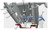
탄성부재(400)는, 탄성을 가지는 소재 또는 탄성을 가지게끔 형성될 수 있으며, 일 예로 스프링을 들 수 있다. 이러한 탄성부재(400)는 도 2 내지 도 4에 도시된 바와 같이 가이드바(100)와 나란하게 설치되며, 이에 따라 이동체(200)가 자중에 의해 이동하는 방향과 반대 방향인 후방 상측을 향해 탄성력이 작용된다. 이때, 탄성부재(400)를 가이드바(100)와 나란히 설치되게 하면서, 이동체(200)의 이동에 간섭되지 않도록 하기 위하여, 도 4에 도시된 바와 같이 이동체(200)는 두 개의 이동구(210) 하단부 하측을 상호 연결하는 고정구(250)를 더 포함할 수 있다. 이에 따라, 탄성부재(400)인 스프링은 일단이 제1 결합판(800)의 고정면(820) 중앙에 결합되고 타단이 고정구(250) 중앙에 결합될 수 있다. 이때, 제2 프레임(600)은 스프링이 설치됨에 있어, 간섭되지 않게끔 도 3에 도시된 바와 같이 스프링의 일단부가 지나는 간섭방지홀(610)이 전후방향으로 관통형성될 수 있다.The
상술한 본 발명인 하체 단련용 운동기구는, 가이드바(100)를 따라 전방을 향해 하향 경사진 방향으로 자중에 의해 이동되는 이동체(200)가, 탄성부재(400)에 의해 자중의 반대방향으로 탄성력의 작용을 받게 되는바, 여성 등과 같이 하체 근력이 부족한 사용자도 이동체(200)에 기댄 상태에서 하체를 굽혔다 폈다를 반복하며 용이하게 이동체(200)를 이동시킬 수 있으므로 하체를 효과적으로 단련시킬 수 있다.In the above-described exercise device for training the lower body of the present invention, the
한편, 본 발명은 운동을 한 후 사용자가 본 발명으로부터 내려오거나, 운동을 하지 않을 때 이동체(200)가 움직이지 않도록 하는 구성을 더 포함할 수 있다. 이를 위해, 본 발명은 제4 프레임(1000)을 더 포함할 수 있으며, 이동체(200)는 조작봉(260)과 걸림구(270)를 더 포함할 수 있다.Meanwhile, the present invention may further include a configuration for preventing the
구체적으로, 제4 프레임(1000)은 도 2, 도 4 및 도 5에 도시된 바와 같이 일자인 바(bar) 형태로 형성되어, 가이드바(100)와 동일한 경사를 이루도록 일단이 제1 결합면(810)에 결합되고 타단이 제2 결합면(910)에 결합되며 플레이트(220)의 하측에 구비된다. 그리고 제4 프레임(1000)에는, 도 5에 도시된 바와 같이 소정의 간격마다 후방 상측을 향해 나뭇가지가 뻗은 형태를 이루는 걸림돌기(1110)가 형성된 위치고정바(1100)가 길이방향을 따라 상면에 구비된다. 즉, 위치고정바(1100)에는 복수 개의 걸림돌기(1110)가 소정의 간격마다 형성된다. 그리고 걸림돌기(1110)와 걸림돌기(1110)가 형성되지 않은 위치고정바(1100) 부분의 사이에는 걸림홈이 형성된다. 또한, 걸림돌기(1110)는 걸림돌기(110)가 형성되지 않은 위치고정바(1100) 부분으로부터 후방 상측을 향해 상향 경사지도록 형성될 수 있다.Specifically, the
조작봉(260)은 일 예로, 도 5 및 도 6에 도시된 바와 같이 봉 형태를 이루며 플레이트(220)의 양 측벽에 회전가능하게 결합되고 일 측벽을 관통하여 전방을 향해 절곡되게 구비된다. 걸림구(270)는 도 5 및 도 6에 도시된 바와 같이 플레이트(220) 내측에서 조작봉(260)과 함께 회전되게끔 조작봉(260)에 결합된다. 조작봉(260)과 함께 회전되는 걸림구(270)의 끝단은 걸림홈에 위치되면서 걸림돌기(1110)와 걸림이 발생될 수 있다.The operating
따라서, 사용자가 운동 후 조작봉(260)을 일방향으로 회전시키고 이동체(200)를 하방으로 이동시키면, 일 걸림돌기(1110)와 걸림구(270) 간의 걸림이 발생되어, 이동체(200)가 하방으로 더이상 이동되지 않는 잠금된 상태를 이루게 된다. 이후, 사용자가 운동을 하고자 발판(300)에 발을 지지하고 이동체(200)에 엉덩이와 등을 기댄 상태에서 무릎을 펴, 고정된 상태를 이루는 이동체(200)를 상방으로 이동시키면, 걸림구(270)는 걸림이 발생되었던 일 걸림돌기(1110)의 인접한 상측에 위치하는 타 걸림돌기(1110)를 따라 이동되며, 이로 인해 조작봉(260)이 타방향으로 회전되어 걸림이 해제되는바, 자동으로 잠금된 상태를 해제할 수 있다.Therefore, when the user rotates the
상술한 바와 같이, 본 발명은 운동을 한 후 사용자가 본 발명으로부터 내려오거나 운동을 하지 않을 때 이동체(200)가 움직이지 않도록 이동체(200)를 잠글 수 있어, 사용자의 안전을 확보할 수 있으며, 잠금된 이동체(200)를 상방으로 밀기만 하면 해제되는바, 사용자는 편리하게 잠금을 해제할 수 있다.As described above, the present invention can lock the
100 : 가이드바
200 : 이동체210 : 이동구
220 : 플레이트230 : 제1 시트
240 : 제2 시트250 : 고정구
260 : 조작봉270 : 걸림구
280 : 손잡이290 : 끼움봉
300 : 발판
400 : 탄성부재
500 : 제1 프레임510 : 수직부
520 : 수평부530 : 경사부
600 : 제2 프레임610 : 간섭방지홀
700 : 제3 프레임
800 : 제1 결합판810 : 제1 결합면
820 : 고정면
900 : 제2 결합판910 : 제2 결합면
1000 : 제4 프레임1100 : 위치고정바
1110 : 걸림돌기100: guide bar
200: moving body 210: moving sphere
220: plate 230: first sheet
240: second sheet 250: fixture
260: control bar 270: hook
280: handle 290: fitting rod
300: scaffolding
400: elastic member
500: first frame 510: vertical part
520: horizontal part 530: inclined part
600: second frame 610: interference prevention hole
700: 3rd frame
800: first coupling plate 810: first coupling surface
820: fixed surface
900: second coupling plate 910: second coupling surface
1000: 4th frame 1100: position fixing bar
1110: stumbling block
Claims (5)
Translated fromKorean상기 가이드바(100)를 따라 이동하며 사용자의 엉덩이와 등이 기대어지는 이동체(200);
상기 가이드바(100)의 전방 측에 구비되며 전방을 향해 상향 경사지게 구비되어, 사용자의 발이 지지되는 발판(300);을 포함하되,
상기 이동체(200)는, 가이드바(100)와 나란하게 설치되는 탄성부재(400)에 의해, 후방 상측을 향해 탄성력이 작용되고,
수직부(510)와 수평부(520)가 'ㄴ'자 형태를 이루고, 상기 수평부(520) 끝단으로부터 전방을 향해 상향 경사지게 경사부(530)가 형성되며, 마찰력이 작용하는 소재로 이루어지고, 기설정된 간격으로 구비되는 다수의 바닥패킹(미도시)를 포함하며, 두 개가 측방향으로 이격배치되는 제1 프레임(500);
두 개의 제1 프레임(500)의 수직부(510) 상부를 연결하는 제2 프레임(600);
두 개의 제1 프레임(500)의 수평부(520) 끝단부를 연결하는 제3 프레임(700);
전방을 향해 상향 경사진 제1 결합면(810)을 포함하면서 제2 프레임(600)에 결합되는 제1 결합판(800);
전방을 향해 상향 경사진 제2 결합면(910)을 포함하면서 제3 프레임(700)에 결합되는 제2 결합판(900);을 더 포함하되,
상기 가이드바(100)는, 일단이 제1 결합면(810)에 결합되고 타단이 제2 결합면(910)에 결합되며, 상기 발판(300)은, 상기 경사부(530)에 결합되고,
상기 가이드바(100)는 두 개가 상호 이격되게끔 배치되어, 상기 이동체(200)가 두 개의 가이드바(100)를 따라 이동하되,
상기 이동체(200)는, 상기 두 개의 가이드바(100) 상에 각각 구비되어 가이드바(100)를 따라 이동되고, 기설정된 길이의 통 형상으로 마련되는 두 개의 이동구(210)와, 종단면이 하방으로 개방된 'ㄷ'자 형태를 이루며 양 측벽이 인접한 이동구(210)에 결합되고, 상기 가이드바(100)가 이격된 거리보다 좁은 길이로 마련되는 플레이트(220)와, 상기 플레이트(220) 상면에 구비되며 사용자의 엉덩이가 기대어지는 제1 시트(230)와, 상기 제1 시트(230)보다 상측에 위치되게끔 플레이트(220) 상면에 구비되며 사용자의 등이 기대어지는 제2 시트(240)를 포함하며,
상기 제1 시트(230) 및 제2 시트(240)는 각각 쿠션 소재로 이루어진 판 형상으로 마련되고, 상기 제1 시트(230) 및 제2 시트(240)는 둔각을 이루도록 배치되며,
상기 이동구(210)는 상기 가이드바(100)가 관통되도록 길이 방향을 따라 중앙에 관통홀(미도시)을 포함하고,
상기 이동체(200)는, 두 개의 이동구(210) 하단부 하측을 상호 연결하는 고정구(250);를 더 포함하며,
상기 제1 결합판(800)은 제2 프레임(600)의 후측에 결합되는 고정면(820)을 더 포함하되,
상기 탄성부재(400)는, 일단이 고정면(820) 중앙에 결합되고 타단이 고정구(250)에 결합되는 스프링이며,
상기 제2 프레임(600)은, 스프링의 일단부가 지나는 간섭방지홀(610)이 관통형성되며,
상기 가이드바(100)와 동일한 경사를 이루면서 일단이 제1 결합면(810)에 결합되고 타단이 제2 결합면(910)에 결합되며 플레이트(220)의 하측에 구비되는 제4 프레임(1000);을 더 포함하되,
상기 제4 프레임(1000)은, 소정의 간격마다 후방 상측을 향해 나뭇가지가 뻗은 형태를 이루는 걸림돌기(1110)가 형성된 위치고정바(1100)가 길이방향을 따라 상면에 구비되고, 상기 걸림돌기(1110) 일측에는 걸림홀(미도시)이 형성되며,
상기 이동체(200)는, 봉 형태를 이루며 플레이트(220)의 양 측벽에 회전가능하게 결합되고 일 측벽을 관통하여 전방을 향해 절곡된 조작봉(260);
상기 플레이트(220) 내측에서 조작봉(260)과 함께 회전되게끔 조작봉(260)에 결합되는 걸림구(270);
'ㄱ'자로 절곡된 봉 형상으로 마련되고, 상기 제1 시트(230)와 인접하도록 상기 플레이트(220)의 양 측벽에 전방을 향하도록 마련되는 손잡이(280); 및
기설정된 길이를 가지는 봉 형상으로 마련되고, 제2 시트(240)의 상측에 위치되도록 상기 플레이트(220)의 상면에 구비되며, 양단에 중량물이 끼워지는 끼움봉(290);
을 더 포함하여,
상기 조작봉(260)의 일방향 회전 후 이동체(200)의 하방 이동에 따라, 상기 조작봉(260)과 함께 회전되는 상기 걸림구(270)의 끝단은 상기 걸림홀에 위치되면서 일 걸림돌기(1110)와 걸림이 발생이 발생되고,
상기 이동체(200)의 상방 이동시 일 걸림돌기(1110)의 인접한 상측에 위치하는 타 걸림돌기(1110)를 따라 걸림구(270)가 이동되면서 조작봉(260)이 타방향으로 회전되어 걸림이 자동으로 해제되며,
상기 발판(300)은 상기 두 개의 제1 프레임(500)의 경사부(530)에 양측 가장자리가 결합되어 구비되는 것 특징으로 하는 하체 단련용 운동기구.A guide bar 100 installed inclined downward toward the front;
A moving body 200 that moves along the guide bar 100 and leans on the user's hips and back;
A footrest 300 provided on the front side of the guide bar 100 and inclined upward toward the front to support the user's feet; including,
In the movable body 200, an elastic force is applied toward the rear and upper side by the elastic member 400 installed in parallel with the guide bar 100,
The vertical portion 510 and the horizontal portion 520 form a 'b' shape, and the inclined portion 530 is formed to incline upward toward the front from the end of the horizontal portion 520, and is made of a material to which frictional force acts. , A first frame 500 including a plurality of bottom packings (not shown) provided at predetermined intervals, two of which are spaced apart in the lateral direction;
a second frame 600 connecting upper portions of the vertical portions 510 of the two first frames 500;
A third frame 700 connecting the ends of the horizontal portions 520 of the two first frames 500;
A first coupling plate 800 coupled to the second frame 600 while including a first coupling surface 810 inclined upward toward the front;
A second coupling plate 900 coupled to the third frame 700 while including a second coupling surface 910 inclined upward toward the front; further comprising,
The guide bar 100 has one end coupled to the first coupling surface 810 and the other end coupled to the second coupling surface 910, and the scaffold 300 is coupled to the inclined portion 530,
The two guide bars 100 are arranged to be spaced apart from each other, so that the movable body 200 moves along the two guide bars 100,
The movable body 200 is provided on the two guide bars 100, moves along the guide bar 100, and has two moving parts 210 provided in a tubular shape with a predetermined length, and a longitudinal section A plate 220 formed in a 'c' shape open downward, both side walls coupled to adjacent moving devices 210, and provided with a length narrower than the distance at which the guide bar 100 is spaced apart, and the plate 220 ) A first sheet 230 provided on the upper surface and on which the user's hip leans, and a second sheet provided on the upper surface of the plate 220 so as to be positioned above the first sheet 230 and on which the user's back is leaned ( 240),
The first seat 230 and the second seat 240 are each provided in a plate shape made of a cushion material, and the first seat 230 and the second seat 240 are disposed to form an obtuse angle,
The moving tool 210 includes a through hole (not shown) in the center along the longitudinal direction so that the guide bar 100 passes through,
The movable body 200 further includes a fixture 250 interconnecting the lower ends of the two movable devices 210,
The first coupling plate 800 further includes a fixing surface 820 coupled to the rear side of the second frame 600,
The elastic member 400 is a spring having one end coupled to the center of the fixing surface 820 and the other end coupled to the fixture 250,
The second frame 600 has an interference prevention hole 610 through which one end of the spring passes,
A fourth frame 1000 having one end coupled to the first coupling surface 810 and the other end coupled to the second coupling surface 910 provided at the lower side of the plate 220 while forming the same inclination as the guide bar 100 ; Including more,
The fourth frame 1000 is provided with a position fixing bar 1100 along the longitudinal direction formed on the upper surface of the fourth frame 1000 having a protrusion 1110 forming a shape in which branches extend toward the rear upper side at predetermined intervals, and the protrusion (1110) A locking hole (not shown) is formed on one side,
The movable body 200 includes a control bar 260 formed in a bar shape and rotatably coupled to both side walls of the plate 220 and bent toward the front through one side wall;
A locking member 270 coupled to the operating rod 260 so as to be rotated together with the operating rod 260 inside the plate 220;
Handles 280 provided in a bar shape bent in a 'ㄱ' shape and provided facing forward on both side walls of the plate 220 so as to be adjacent to the first sheet 230; and
It is provided in the shape of a rod having a predetermined length, provided on the upper surface of the plate 220 so as to be positioned on the upper side of the second sheet 240, and a fitting rod 290 into which a heavy object is inserted at both ends;
Including more,
As the moving body 200 moves downward after the one-way rotation of the control rod 260, the end of the locking sphere 270 rotated together with the control rod 260 is positioned in the locking hole, and one locking protrusion 1110 ) and jamming occurs,
When the movable body 200 moves upward, the locking member 270 is moved along the other locking protrusion 1110 located on the upper side adjacent to the one locking protrusion 1110, and the control rod 260 is rotated in the other direction, so that the locking is automatically performed. is released with
The footrest 300 is an exercise device for lower body training, characterized in that the edges of both sides are coupled to the inclined portions 530 of the two first frames 500.
Priority Applications (1)
| Application Number | Priority Date | Filing Date | Title |
|---|---|---|---|
| KR1020200154672AKR102474978B1 (en) | 2020-11-18 | 2020-11-18 | Exercise device for training lower body |
Applications Claiming Priority (1)
| Application Number | Priority Date | Filing Date | Title |
|---|---|---|---|
| KR1020200154672AKR102474978B1 (en) | 2020-11-18 | 2020-11-18 | Exercise device for training lower body |
Publications (2)
| Publication Number | Publication Date |
|---|---|
| KR20220000325A KR20220000325A (en) | 2022-01-03 |
| KR102474978B1true KR102474978B1 (en) | 2022-12-06 |
Family
ID=79348623
Family Applications (1)
| Application Number | Title | Priority Date | Filing Date |
|---|---|---|---|
| KR1020200154672AActiveKR102474978B1 (en) | 2020-11-18 | 2020-11-18 | Exercise device for training lower body |
Country Status (1)
| Country | Link |
|---|---|
| KR (1) | KR102474978B1 (en) |
Families Citing this family (1)
| Publication number | Priority date | Publication date | Assignee | Title |
|---|---|---|---|---|
| KR102765742B1 (en)* | 2022-01-18 | 2025-02-11 | 이범재 | Exercise equipment to train the lower body |
Citations (2)
| Publication number | Priority date | Publication date | Assignee | Title |
|---|---|---|---|---|
| US20180207469A1 (en)* | 2012-09-18 | 2018-07-26 | Judith Miriam ARONSON | Pilates reformer |
| US20190070449A1 (en)* | 2017-09-01 | 2019-03-07 | Scott G. Naidus | Leg press machine with a weight plate transfer system for reducing exercise resistance while remaining seated |
Family Cites Families (3)
| Publication number | Priority date | Publication date | Assignee | Title |
|---|---|---|---|---|
| KR20030016938A (en) | 2001-08-23 | 2003-03-03 | 전위성 | The machine for exercise of the lower part of the body |
| KR101981145B1 (en)* | 2017-09-28 | 2019-05-22 | 최정훈 | Multi health exercise machine |
| KR20190001647U (en)* | 2017-12-21 | 2019-07-01 | 변현정 | Squat training machine |
- 2020
- 2020-11-18KRKR1020200154672Apatent/KR102474978B1/enactiveActive
Patent Citations (2)
| Publication number | Priority date | Publication date | Assignee | Title |
|---|---|---|---|---|
| US20180207469A1 (en)* | 2012-09-18 | 2018-07-26 | Judith Miriam ARONSON | Pilates reformer |
| US20190070449A1 (en)* | 2017-09-01 | 2019-03-07 | Scott G. Naidus | Leg press machine with a weight plate transfer system for reducing exercise resistance while remaining seated |
Also Published As
| Publication number | Publication date |
|---|---|
| KR20220000325A (en) | 2022-01-03 |
Similar Documents
| Publication | Publication Date | Title |
|---|---|---|
| US5626548A (en) | Lower-body exercise machine | |
| KR101720874B1 (en) | Squat exercise device | |
| US5529558A (en) | Exercise apparatus | |
| US6231489B1 (en) | Device for multiple torso exercises | |
| US9168165B2 (en) | Squat and lunge training device | |
| KR200486552Y1 (en) | Barbell Exercise Equipment | |
| KR102474978B1 (en) | Exercise device for training lower body | |
| US8105216B2 (en) | Exercise device for stomach muscles | |
| KR101875338B1 (en) | Safety Squat Training Machine to Protect Knee Joints | |
| KR101957566B1 (en) | Lunge exercise machine | |
| TWI632936B (en) | Squat fitness machine | |
| KR100943968B1 (en) | A lower limbs evaluation for function rehabilitation exercise device | |
| US6485400B1 (en) | Gymnastic means | |
| CN107617194B (en) | Multi-functional squatting and standing body-building device | |
| KR101870101B1 (en) | Squat exercise apparatus transformable to roman chair | |
| KR101975563B1 (en) | Exercise apparatus for squat | |
| KR20110089913A (en) | Lower Body and Abs Exercises | |
| KR102264153B1 (en) | Exercise equipment to strengthen gluteal muscles | |
| CN214286552U (en) | Exercise device | |
| KR102262359B1 (en) | Lower body exercise apparatus | |
| CN205586422U (en) | Auxiliary device deeply squats | |
| EP1955735B1 (en) | Trampoline | |
| KR102115694B1 (en) | Exercise machine for squat | |
| KR101540538B1 (en) | Waist exercising apparatus | |
| KR102802708B1 (en) | Drop type power leg press machine |
Legal Events
| Date | Code | Title | Description |
|---|---|---|---|
| PA0109 | Patent application | Patent event code:PA01091R01D Comment text:Patent Application Patent event date:20201118 | |
| PA0201 | Request for examination | ||
| G15R | Request for early publication | ||
| PG1501 | Laying open of application | Comment text:Request for Early Opening Patent event code:PG15011R01I Patent event date:20211215 | |
| E902 | Notification of reason for refusal | ||
| PE0902 | Notice of grounds for rejection | Comment text:Notification of reason for refusal Patent event date:20220711 Patent event code:PE09021S01D | |
| E701 | Decision to grant or registration of patent right | ||
| PE0701 | Decision of registration | Patent event code:PE07011S01D Comment text:Decision to Grant Registration Patent event date:20221109 | |
| GRNT | Written decision to grant | ||
| PR0701 | Registration of establishment | Comment text:Registration of Establishment Patent event date:20221201 Patent event code:PR07011E01D | |
| PR1002 | Payment of registration fee | Payment date:20221201 End annual number:3 Start annual number:1 | |
| PG1601 | Publication of registration |