KR102473884B1 - Wearable apparatus for assistance and operating method thereof - Google Patents
Wearable apparatus for assistance and operating method thereofDownload PDFInfo
- Publication number
- KR102473884B1 KR102473884B1KR1020170102103AKR20170102103AKR102473884B1KR 102473884 B1KR102473884 B1KR 102473884B1KR 1020170102103 AKR1020170102103 AKR 1020170102103AKR 20170102103 AKR20170102103 AKR 20170102103AKR 102473884 B1KR102473884 B1KR 102473884B1
- Authority
- KR
- South Korea
- Prior art keywords
- frame
- driving unit
- wearable
- user
- assistive device
- Prior art date
- Legal status (The legal status is an assumption and is not a legal conclusion. Google has not performed a legal analysis and makes no representation as to the accuracy of the status listed.)
- Active
Links
- 238000011017operating methodMethods0.000title1
- 230000001939inductive effectEffects0.000claimsdescription5
- 210000001624hipAnatomy0.000description88
- 210000000689upper legAnatomy0.000description15
- 238000000034methodMethods0.000description12
- 238000012545processingMethods0.000description10
- 210000003127kneeAnatomy0.000description7
- 238000010586diagramMethods0.000description6
- 210000004394hip jointAnatomy0.000description5
- 230000004044responseEffects0.000description4
- 210000002414legAnatomy0.000description3
- 230000014509gene expressionEffects0.000description2
- 238000012986modificationMethods0.000description2
- 230000004048modificationEffects0.000description2
- 230000003387muscularEffects0.000description2
- 238000012546transferMethods0.000description2
- 208000027418Wounds and injuryDiseases0.000description1
- 210000001015abdomenAnatomy0.000description1
- 230000032683agingEffects0.000description1
- 210000001217buttockAnatomy0.000description1
- 238000004590computer programMethods0.000description1
- 230000006378damageEffects0.000description1
- 230000005484gravityEffects0.000description1
- 208000014674injuryDiseases0.000description1
- 210000001503jointAnatomy0.000description1
- 230000003287optical effectEffects0.000description1
- 238000005728strengtheningMethods0.000description1
Images


Classifications
- A—HUMAN NECESSITIES
- A61—MEDICAL OR VETERINARY SCIENCE; HYGIENE
- A61H—PHYSICAL THERAPY APPARATUS, e.g. DEVICES FOR LOCATING OR STIMULATING REFLEX POINTS IN THE BODY; ARTIFICIAL RESPIRATION; MASSAGE; BATHING DEVICES FOR SPECIAL THERAPEUTIC OR HYGIENIC PURPOSES OR SPECIFIC PARTS OF THE BODY
- A61H1/00—Apparatus for passive exercising; Vibrating apparatus; Chiropractic devices, e.g. body impacting devices, external devices for briefly extending or aligning unbroken bones
- A61H1/02—Stretching or bending or torsioning apparatus for exercising
- A61H1/0237—Stretching or bending or torsioning apparatus for exercising for the lower limbs
- A61H1/0255—Both knee and hip of a patient, e.g. in supine or sitting position, the feet being moved together in a plane substantially parallel to the body-symmetrical plane
- A61H1/0262—Walking movement; Appliances for aiding disabled persons to walk
- A—HUMAN NECESSITIES
- A61—MEDICAL OR VETERINARY SCIENCE; HYGIENE
- A61F—FILTERS IMPLANTABLE INTO BLOOD VESSELS; PROSTHESES; DEVICES PROVIDING PATENCY TO, OR PREVENTING COLLAPSING OF, TUBULAR STRUCTURES OF THE BODY, e.g. STENTS; ORTHOPAEDIC, NURSING OR CONTRACEPTIVE DEVICES; FOMENTATION; TREATMENT OR PROTECTION OF EYES OR EARS; BANDAGES, DRESSINGS OR ABSORBENT PADS; FIRST-AID KITS
- A61F2/00—Filters implantable into blood vessels; Prostheses, i.e. artificial substitutes or replacements for parts of the body; Appliances for connecting them with the body; Devices providing patency to, or preventing collapsing of, tubular structures of the body, e.g. stents
- A61F2/50—Prostheses not implantable in the body
- A61F2/60—Artificial legs or feet or parts thereof
- A61F2/604—Joints for artificial legs
- A—HUMAN NECESSITIES
- A61—MEDICAL OR VETERINARY SCIENCE; HYGIENE
- A61F—FILTERS IMPLANTABLE INTO BLOOD VESSELS; PROSTHESES; DEVICES PROVIDING PATENCY TO, OR PREVENTING COLLAPSING OF, TUBULAR STRUCTURES OF THE BODY, e.g. STENTS; ORTHOPAEDIC, NURSING OR CONTRACEPTIVE DEVICES; FOMENTATION; TREATMENT OR PROTECTION OF EYES OR EARS; BANDAGES, DRESSINGS OR ABSORBENT PADS; FIRST-AID KITS
- A61F5/00—Orthopaedic methods or devices for non-surgical treatment of bones or joints; Nursing devices ; Anti-rape devices
- A61F5/01—Orthopaedic devices, e.g. long-term immobilising or pressure directing devices for treating broken or deformed bones such as splints, casts or braces
- A61F5/0102—Orthopaedic devices, e.g. long-term immobilising or pressure directing devices for treating broken or deformed bones such as splints, casts or braces specially adapted for correcting deformities of the limbs or for supporting them; Ortheses, e.g. with articulations
- A61F5/0123—Orthopaedic devices, e.g. long-term immobilising or pressure directing devices for treating broken or deformed bones such as splints, casts or braces specially adapted for correcting deformities of the limbs or for supporting them; Ortheses, e.g. with articulations for the knees
- A61F5/0125—Orthopaedic devices, e.g. long-term immobilising or pressure directing devices for treating broken or deformed bones such as splints, casts or braces specially adapted for correcting deformities of the limbs or for supporting them; Ortheses, e.g. with articulations for the knees the device articulating around a single pivot-point
- A—HUMAN NECESSITIES
- A61—MEDICAL OR VETERINARY SCIENCE; HYGIENE
- A61H—PHYSICAL THERAPY APPARATUS, e.g. DEVICES FOR LOCATING OR STIMULATING REFLEX POINTS IN THE BODY; ARTIFICIAL RESPIRATION; MASSAGE; BATHING DEVICES FOR SPECIAL THERAPEUTIC OR HYGIENIC PURPOSES OR SPECIFIC PARTS OF THE BODY
- A61H1/00—Apparatus for passive exercising; Vibrating apparatus; Chiropractic devices, e.g. body impacting devices, external devices for briefly extending or aligning unbroken bones
- A61H1/02—Stretching or bending or torsioning apparatus for exercising
- A61H1/0237—Stretching or bending or torsioning apparatus for exercising for the lower limbs
- A61H1/0244—Hip
- A—HUMAN NECESSITIES
- A61—MEDICAL OR VETERINARY SCIENCE; HYGIENE
- A61H—PHYSICAL THERAPY APPARATUS, e.g. DEVICES FOR LOCATING OR STIMULATING REFLEX POINTS IN THE BODY; ARTIFICIAL RESPIRATION; MASSAGE; BATHING DEVICES FOR SPECIAL THERAPEUTIC OR HYGIENIC PURPOSES OR SPECIFIC PARTS OF THE BODY
- A61H3/00—Appliances for aiding patients or disabled persons to walk about
- A—HUMAN NECESSITIES
- A63—SPORTS; GAMES; AMUSEMENTS
- A63B—APPARATUS FOR PHYSICAL TRAINING, GYMNASTICS, SWIMMING, CLIMBING, OR FENCING; BALL GAMES; TRAINING EQUIPMENT
- A63B21/00—Exercising apparatus for developing or strengthening the muscles or joints of the body by working against a counterforce, with or without measuring devices
- A63B21/40—Interfaces with the user related to strength training; Details thereof
- A63B21/4001—Arrangements for attaching the exercising apparatus to the user's body, e.g. belts, shoes or gloves specially adapted therefor
- A63B21/4011—Arrangements for attaching the exercising apparatus to the user's body, e.g. belts, shoes or gloves specially adapted therefor to the lower limbs
- B—PERFORMING OPERATIONS; TRANSPORTING
- B25—HAND TOOLS; PORTABLE POWER-DRIVEN TOOLS; MANIPULATORS
- B25J—MANIPULATORS; CHAMBERS PROVIDED WITH MANIPULATION DEVICES
- B25J9/00—Programme-controlled manipulators
- B25J9/0006—Exoskeletons, i.e. resembling a human figure
- A—HUMAN NECESSITIES
- A61—MEDICAL OR VETERINARY SCIENCE; HYGIENE
- A61B—DIAGNOSIS; SURGERY; IDENTIFICATION
- A61B5/00—Measuring for diagnostic purposes; Identification of persons
- A61B5/103—Measuring devices for testing the shape, pattern, colour, size or movement of the body or parts thereof, for diagnostic purposes
- A61B5/11—Measuring movement of the entire body or parts thereof, e.g. head or hand tremor or mobility of a limb
- A61B5/1113—Local tracking of patients, e.g. in a hospital or private home
- A61B5/1114—Tracking parts of the body
- A—HUMAN NECESSITIES
- A61—MEDICAL OR VETERINARY SCIENCE; HYGIENE
- A61F—FILTERS IMPLANTABLE INTO BLOOD VESSELS; PROSTHESES; DEVICES PROVIDING PATENCY TO, OR PREVENTING COLLAPSING OF, TUBULAR STRUCTURES OF THE BODY, e.g. STENTS; ORTHOPAEDIC, NURSING OR CONTRACEPTIVE DEVICES; FOMENTATION; TREATMENT OR PROTECTION OF EYES OR EARS; BANDAGES, DRESSINGS OR ABSORBENT PADS; FIRST-AID KITS
- A61F2/00—Filters implantable into blood vessels; Prostheses, i.e. artificial substitutes or replacements for parts of the body; Appliances for connecting them with the body; Devices providing patency to, or preventing collapsing of, tubular structures of the body, e.g. stents
- A61F2/50—Prostheses not implantable in the body
- A61F2/68—Operating or control means
- A61F2/70—Operating or control means electrical
- A—HUMAN NECESSITIES
- A61—MEDICAL OR VETERINARY SCIENCE; HYGIENE
- A61H—PHYSICAL THERAPY APPARATUS, e.g. DEVICES FOR LOCATING OR STIMULATING REFLEX POINTS IN THE BODY; ARTIFICIAL RESPIRATION; MASSAGE; BATHING DEVICES FOR SPECIAL THERAPEUTIC OR HYGIENIC PURPOSES OR SPECIFIC PARTS OF THE BODY
- A61H2201/00—Characteristics of apparatus not provided for in the preceding codes
- A61H2201/16—Physical interface with patient
- A61H2201/1602—Physical interface with patient kind of interface, e.g. head rest, knee support or lumbar support
- A61H2201/164—Feet or leg, e.g. pedal
- A61H2201/1642—Holding means therefor
- A—HUMAN NECESSITIES
- A61—MEDICAL OR VETERINARY SCIENCE; HYGIENE
- A61H—PHYSICAL THERAPY APPARATUS, e.g. DEVICES FOR LOCATING OR STIMULATING REFLEX POINTS IN THE BODY; ARTIFICIAL RESPIRATION; MASSAGE; BATHING DEVICES FOR SPECIAL THERAPEUTIC OR HYGIENIC PURPOSES OR SPECIFIC PARTS OF THE BODY
- A61H2201/00—Characteristics of apparatus not provided for in the preceding codes
- A61H2201/16—Physical interface with patient
- A61H2201/1602—Physical interface with patient kind of interface, e.g. head rest, knee support or lumbar support
- A61H2201/165—Wearable interfaces
- A61H2201/1652—Harness
- A—HUMAN NECESSITIES
- A61—MEDICAL OR VETERINARY SCIENCE; HYGIENE
- A61H—PHYSICAL THERAPY APPARATUS, e.g. DEVICES FOR LOCATING OR STIMULATING REFLEX POINTS IN THE BODY; ARTIFICIAL RESPIRATION; MASSAGE; BATHING DEVICES FOR SPECIAL THERAPEUTIC OR HYGIENIC PURPOSES OR SPECIFIC PARTS OF THE BODY
- A61H2201/00—Characteristics of apparatus not provided for in the preceding codes
- A61H2201/50—Control means thereof
- A61H2201/5007—Control means thereof computer controlled
- A—HUMAN NECESSITIES
- A61—MEDICAL OR VETERINARY SCIENCE; HYGIENE
- A61H—PHYSICAL THERAPY APPARATUS, e.g. DEVICES FOR LOCATING OR STIMULATING REFLEX POINTS IN THE BODY; ARTIFICIAL RESPIRATION; MASSAGE; BATHING DEVICES FOR SPECIAL THERAPEUTIC OR HYGIENIC PURPOSES OR SPECIFIC PARTS OF THE BODY
- A61H2201/00—Characteristics of apparatus not provided for in the preceding codes
- A61H2201/50—Control means thereof
- A61H2201/5023—Interfaces to the user
- A61H2201/5025—Activation means
- A61H2201/503—Inertia activation, i.e. activated by movement
- A—HUMAN NECESSITIES
- A61—MEDICAL OR VETERINARY SCIENCE; HYGIENE
- A61H—PHYSICAL THERAPY APPARATUS, e.g. DEVICES FOR LOCATING OR STIMULATING REFLEX POINTS IN THE BODY; ARTIFICIAL RESPIRATION; MASSAGE; BATHING DEVICES FOR SPECIAL THERAPEUTIC OR HYGIENIC PURPOSES OR SPECIFIC PARTS OF THE BODY
- A61H2201/00—Characteristics of apparatus not provided for in the preceding codes
- A61H2201/50—Control means thereof
- A61H2201/5053—Control means thereof mechanically controlled
Landscapes
- Health & Medical Sciences (AREA)
- Life Sciences & Earth Sciences (AREA)
- General Health & Medical Sciences (AREA)
- Animal Behavior & Ethology (AREA)
- Veterinary Medicine (AREA)
- Public Health (AREA)
- Physical Education & Sports Medicine (AREA)
- Engineering & Computer Science (AREA)
- Orthopedic Medicine & Surgery (AREA)
- Rehabilitation Therapy (AREA)
- Epidemiology (AREA)
- Pain & Pain Management (AREA)
- Biomedical Technology (AREA)
- Heart & Thoracic Surgery (AREA)
- Vascular Medicine (AREA)
- Nursing (AREA)
- Transplantation (AREA)
- Oral & Maxillofacial Surgery (AREA)
- Mechanical Engineering (AREA)
- Robotics (AREA)
- Cardiology (AREA)
- Biophysics (AREA)
- Rehabilitation Tools (AREA)
- Manipulator (AREA)
- Physiology (AREA)
- Pathology (AREA)
- Medical Informatics (AREA)
- Molecular Biology (AREA)
- Surgery (AREA)
- Physics & Mathematics (AREA)
- Dentistry (AREA)
Abstract
Translated fromKoreanDescription
Translated fromKorean아래의 설명은 착용형 보조 장치 및 그 동작 방법에 관한 것이다.The following description relates to a wearable assistive device and an operation method thereof.
오늘날, 노화나 부상 등으로 인해 일상생활이 불편해진 사용자들에게 보조력(assistance power)을 제공하는 착용형 보조 장치가 이용되고 있다. 이를테면, 관절이 불편한 노인이나 환자들이 보행 및 기립을 원활하게 할 수 있도록 근력을 보조하거나 또는 군사용 등의 목적으로 인체의 근력을 강화시키는 형태의 착용형 보조 장치들이 개발되고 있다.Today, wearable assistive devices that provide assistance power to users whose daily lives are inconvenient due to aging or injury are being used. For example, wearable assistive devices in the form of assisting the muscular strength of the elderly or patients with joint discomfort so that they can smoothly walk and stand, or strengthening the muscular strength of the human body for military purposes, have been developed.
미국등록특허 US 8,663,135 (2014.03.04)
미국공개특허 US 2018/0200878 (2018.07.19)US registered patent US 8,663,135 (2014.03.04)
US Patent Publication US 2018/0200878 (2018.07.19)
일측에 따른 착용형 보조 장치는 제1 방향에서 사용자를 보조(assist)하는 힘(power)을 전달하는 제1 프레임, 제2 방향에서 상기 힘을 전달하는 제2 프레임, 상기 제1 방향으로부터 당겨지며 상기 제2 프레임을 상기 사용자에게 밀착시키는 제1 착용부, 상기 제2 방향으로부터 당겨지며 상기 제1 프레임을 상기 사용자에게 밀착시키는 제2 착용부를 포함할 수 있다.A wearable assistive device according to one side includes a first frame that transmits power to assist a user in a first direction, a second frame that transmits the force in a second direction, and a pull from the first direction. It may include a first wearing part that adheres the second frame to the user, and a second wearing part that is pulled in the second direction and adheres the first frame to the user.
일실시예에 따르면, 상기 착용형 보조 장치는 상기 사용자를 보조하는 힘을 생성하는 구동부 및 지정된 타겟 부위에 접촉되며 상기 사용자를 지지하는 지지부를 더 포함할 수 있다.According to one embodiment, the wearable assistive device may further include a driving unit generating a force to assist the user and a support unit contacting a designated target area and supporting the user.
다른 일실시예에 따르면, 상기 착용형 보조 장치는 상기 제1 프레임 및 상기 제2 프레임 중 적어도 하나가 미리 지정된 방향으로 이동하도록 유도하는 가이드부를 더 포함할 수 있다.According to another embodiment, the wearable auxiliary device may further include a guide unit for inducing movement of at least one of the first frame and the second frame in a predetermined direction.
또 다른 일실시예에 따르면, 상기 가이드부는 상기 제1 프레임 및 상기 제2 프레임 중 적어도 하나가 상기 미리 지정된 방향으로 선형 이동되도록 유도할 수 있다.According to another embodiment, the guide unit may induce linear movement of at least one of the first frame and the second frame in the predetermined direction.
또 다른 일실시예에 따르면, 상기 가이드부는 상기 미리 지정된 방향을 따라 연장되는 레일(rail)로 구현되고, 상기 제1 프레임 및 상기 제2 프레임 중 적어도 하나는 상기 레일을 따라 이동할 수 있다.According to another embodiment, the guide part is implemented as a rail extending along the predetermined direction, and at least one of the first frame and the second frame may move along the rail.
또 다른 일실시예에 따르면, 상기 가이드부는 상기 미리 지정된 방향을 따라 이동 경로를 형성하는 가이드 블록으로 구현되고, 상기 제1 프레임 및 상기 제2 프레임 중 적어도 하나는 상기 이동 경로를 따라 이동할 수 있다. 상기 미리 지정된 방향은 상기 구동부에 의해 생성되는 힘의 방향과 직교(orthogonal)할 수 있다.According to another embodiment, the guide unit is implemented as a guide block forming a movement path along the predetermined direction, and at least one of the first frame and the second frame may move along the movement path. The predetermined direction may be orthogonal to a direction of force generated by the driving unit.
또 다른 일실시예에 따르면, 상기 착용형 보조 장치는 상기 제1 착용부와 상기 제2 착용부를 고정하는 체결부를 더 포함할 수 있다. 상기 제1 착용부와 상기 제2 착용부가 체결된 경우에, 상기 제1 프레임 및 상기 제2 프레임은 지정된 타겟 부위에 고정될 수 있다.According to another embodiment, the wearable auxiliary device may further include a fastening part fixing the first wearable part and the second wearable part. When the first wearing part and the second wearing part are fastened, the first frame and the second frame may be fixed to a designated target portion.
또 다른 일실시예에 따르면, 상기 제1 프레임은 상기 제2 착용부의 일단과 연결되고, 상기 제2 프레임은 상기 제1 착용부의 일단과 연결될 수 있다.According to another embodiment, the first frame may be connected to one end of the second wearing part, and the second frame may be connected to one end of the first wearing part.
또 다른 일실시예에 따르면, 상기 제1 프레임은 상기 제1 착용부가 통과하는 제1 중공부를 포함하고 상기 제2 프레임은 상기 제2 착용부가 통과하는 제2 중공부를 포함할 수 있다. 상기 제1 착용부는 상기 제1 중공부를 통과하여 상기 제2 프레임을 이동시키는 제1 힘을 전달하고, 상기 제2 착용부는 상기 제2 중공부를 통과하여 상기 제1 프레임을 이동시키는 제2 힘을 전달할 수 있다.According to another embodiment, the first frame may include a first hollow part through which the first wearing part passes, and the second frame may include a second hollow part through which the second wearing part passes. The first wearing part passes through the first hollow part to transmit a first force for moving the second frame, and the second wearing part passes through the second hollow part to transmit a second force for moving the first frame. can
다른 일측에 따른 착용형 보조 장치는 지정된 타겟 부위에 접촉되며, 사용자를 지지하는 지지부, 상기 사용자를 보조하는 힘을 생성하는 구동부, 상기 힘을 상기 지지부로 전달하는 프레임 및 상기 프레임에 연결되고, 상기 구동부가 미리 지정된 방향으로 선형 이동되도록 유도하는 가이드부를 포함할 수 있다.A wearable assistive device according to another side is in contact with a designated target portion, and is connected to a support portion supporting a user, a driving portion generating a force assisting the user, a frame transmitting the force to the support portion, and the frame, wherein the It may include a guide unit for inducing linear movement of the driving unit in a predetermined direction.
일실시예에 따르면, 상기 미리 지정된 방향은 상기 구동부에 의해 생성되는 회전력의 중심축과 수직인 평면에 존재하는 임의의 방향일 수 있다.According to one embodiment, the predetermined direction may be any direction existing on a plane perpendicular to the central axis of the rotational force generated by the driving unit.
다른 일실시예에 따르면, 상기 가이드부는 상기 미리 지정된 방향을 따라 연장되는 레일을 포함하고, 상기 구동부는 상기 레일을 따라 이동할 수 있다. 또한, 상기 가이드부는 상기 구동부와 연결되어 상기 레일을 따라 이동하는 이동 부재, 상기 레일 상에서 소정 간격으로 배치되는 적어도 하나의 홀(hole) 및 상기 이동 부재와 연결되고 상기 적어도 하나의 홀 중 어느 하나에 삽입되어 상기 구동부를 고정하는 핀(pin)을 더 포함할 수 있다.According to another embodiment, the guide part may include a rail extending along the predetermined direction, and the driving part may move along the rail. In addition, the guide unit is connected to the driving unit and is connected to any one of a movable member moving along the rail, at least one hole disposed on the rail at a predetermined interval, and connected to the movable member and the at least one hole. It may further include a pin for inserting and fixing the drive unit.
또 다른 일실시예에 따르면, 상기 가이드부는 상기 미리 지정된 방향을 따라 이동 경로를 형성하는 가이드 블록, 상기 구동부와 연결되어 상기 이동 경로를 따라 이동하는 이동 부재 및 상기 이동 경로 상에 배치되는 스토퍼(stopper)를 포함하고, 상기 구동부는 상기 이동 경로를 따라 이동할 수 있다. 또한, 상기 가이드 블록은 소정 간격으로 배치되는 복수의 홀을 포함하고, 상기 스토퍼는 상기 복수의 홀 중 어느 하나에 삽입되어 상기 구동부를 고정시킬 수 있다.According to another embodiment, the guide unit includes a guide block forming a movement path along the predetermined direction, a moving member connected to the driving unit and moving along the movement path, and a stopper disposed on the movement path. ), and the driving unit may move along the movement path. In addition, the guide block may include a plurality of holes disposed at predetermined intervals, and the stopper may be inserted into any one of the plurality of holes to fix the driving unit.
도 1은 일실시예에 따른 착용형 보조 장치의 개략적인 구성을 도시하는 블록도이다.
도 2는 도 1에서 설명된 착용형 보조 장치를 도시하는 평면도이다.
도 3은 다른 일실시예에 따른 착용형 보조 장치의 개략적인 구성을 도시하는 블록도이다.
도 4는 도 3에서 설명된 착용형 보조 장치의 동작 방법을 간략히 설명하는 흐름도이다.
도 5a는 일실시예에 따른 가이드부의 동작을 설명하는 평면도이다.
도 5b는 일실시예에 따른 가이드부의 사시도이다.
도 5c는 다른 일실시예에 따른 가이드부의 사시도이다.
도 6은 다른 일실시예에 따른 착용형 보조 장치의 개략적인 구성을 도시하는 예시도이다.
도 7a는 일실시예에 따라 구동부의 위치가 조정되는 착용형 보조 장치의 측면도이다.
도 7b는 다른 일실시예에 따라 구동부의 위치가 조정되는 착용형 보조 장치의 측면도이다.
도 7c는 또 다른 일실시예에 따라 구동부의 위치가 조정되는 착용형 보조 장치의 측면도이다.
도 8a는 일실시예에 따라 구동부에 연결되는 가이드부의 동작을 설명하는 예시도이다.
도 8b는 다른 일실시예에 따라 구동부에 연결되는 가이드부의 동작을 설명하는 예시도이다.
도 9a 내지 도 9c는 다양한 타겟 부위에 접촉되는 착용형 보조 장치의 실시예를 도시하는 예시도이다.1 is a block diagram showing a schematic configuration of a wearable auxiliary device according to an embodiment.
FIG. 2 is a plan view illustrating the wearable auxiliary device described in FIG. 1 .
3 is a block diagram showing a schematic configuration of a wearable auxiliary device according to another embodiment.
FIG. 4 is a flowchart briefly explaining a method of operating the wearable assistive device described in FIG. 3 .
5A is a plan view illustrating an operation of a guide unit according to an exemplary embodiment.
5B is a perspective view of a guide unit according to an embodiment.
5C is a perspective view of a guide unit according to another embodiment.
6 is an exemplary view showing a schematic configuration of a wearable auxiliary device according to another embodiment.
7A is a side view of a wearable auxiliary device in which a position of a driving unit is adjusted according to an exemplary embodiment.
7B is a side view of a wearable auxiliary device in which a position of a driving unit is adjusted according to another embodiment.
7C is a side view of a wearable auxiliary device in which a position of a driving unit is adjusted according to another embodiment.
8A is an exemplary diagram illustrating an operation of a guide unit connected to a driving unit according to an exemplary embodiment.
8B is an exemplary view illustrating an operation of a guide unit connected to a driving unit according to another embodiment.
9A to 9C are exemplary views illustrating embodiments of a wearable auxiliary device in contact with various target areas.
이하, 실시예들을 첨부된 도면을 참조하여 상세하게 설명한다. 그러나, 특허출원의 범위가 이러한 실시예들에 의해 제한되거나 한정되는 것은 아니다. 각 도면에 제시된 동일한 참조 부호는 동일한 부재를 나타낸다.Hereinafter, embodiments will be described in detail with reference to the accompanying drawings. However, the scope of the patent application is not limited or limited by these examples. Like reference numerals in each figure indicate like elements.
아래 설명하는 실시예들에는 다양한 변경이 가해질 수 있다. 아래 설명하는 실시예들은 실시 형태에 대해 한정하려는 것이 아니며, 이들에 대한 모든 변경, 균등물 내지 대체물을 포함하는 것으로 이해되어야 한다.Various changes may be made to the embodiments described below. The embodiments described below are not intended to be limiting on the embodiments, and should be understood to include all modifications, equivalents or substitutes thereto.
실시예에서 사용한 용어는 단지 특정한 실시예를 설명하기 위해 사용된 것으로, 실시예를 한정하려는 의도가 아니다. 단수의 표현은 문맥상 명백하게 다르게 뜻하지 않는 한, 복수 개의 표현을 포함한다. 본 명세서에서, "포함하다" 또는 "가지다" 등의 용어는 명세서 상에 기재된 특징, 숫자, 단계, 동작, 구성 요소, 부품 또는 이들을 조합한 것이 존재함을 지정하려는 것이지, 하나 또는 그 이상의 다른 특징들이나 숫자, 단계, 동작, 구성요소, 부품 또는 이들을 조합한 것들의 존재 또는 부가 가능성을 미리 배제하지 않는 것으로 이해되어야 한다.Terms used in the examples are used only to describe specific examples, and are not intended to limit the examples. Expressions in the singular number include plural expressions unless the context clearly dictates otherwise. In this specification, terms such as "include" or "have" are intended to designate that there is a feature, number, step, operation, component, part, or combination thereof described in the specification, but one or more other features It should be understood that the presence or addition of numbers, steps, operations, components, parts, or combinations thereof is not precluded.
다르게 정의되지 않는 한, 기술적이거나 과학적인 용어를 포함해서 여기서 사용되는 모든 용어들은 실시예가 속하는 기술 분야에서 통상의 지식을 가진 자에 의해 일반적으로 이해되는 것과 동일한 의미를 가지고 있다. 일반적으로 사용되는 사전에 정의되어 있는 것과 같은 용어들은 관련 기술의 문맥 상 가지는 의미와 일치하는 의미를 가지는 것으로 해석되어야 하며, 본 출원에서 명백하게 정의하지 않는 한, 이상적이거나 과도하게 형식적인 의미로 해석되지 않는다.Unless defined otherwise, all terms used herein, including technical or scientific terms, have the same meaning as commonly understood by a person of ordinary skill in the art to which the embodiment belongs. Terms such as those defined in commonly used dictionaries should be interpreted as having a meaning consistent with the meaning in the context of the related art, and unless explicitly defined in the present application, they should not be interpreted in an ideal or excessively formal meaning. don't
또한, 첨부 도면을 참조하여 설명함에 있어, 도면 부호에 관계없이 동일한 구성 요소는 동일한 참조 부호를 부여하고 이에 대한 중복되는 설명은 생략하기로 한다. 실시예를 설명함에 있어서 관련된 공지 기술에 대한 구체적인 설명이 실시예의 요지를 불필요하게 흐릴 수 있다고 판단되는 경우 그 상세한 설명을 생략한다.In addition, in the description with reference to the accompanying drawings, the same reference numerals are given to the same components regardless of reference numerals, and overlapping descriptions thereof will be omitted. In describing the embodiment, if it is determined that a detailed description of a related known technology may unnecessarily obscure the gist of the embodiment, the detailed description will be omitted.
도 1은 일실시예에 따른 착용형 보조 장치의 개략적인 구성을 도시하는 블록도이다. 도 1을 참조하면, 착용형 보조 장치(100)는 사용자에게 착용되어 사용자의 운동을 보조할 수 있다. 이하에서는 착용형 보조 장치(100)가 사람에게 착용되는 실시예를 설명하나, 이는 이해를 돕기 위한 예시적 기재일 뿐 다른 실시예를 제한하거나 한정하는 것으로 해석되어서는 안될 것이다. 이를테면, 착용형 보조 장치(100)는 개와 같은 동물에게도 착용될 수 있을 것이다.1 is a block diagram showing a schematic configuration of a wearable auxiliary device according to an embodiment. Referring to FIG. 1 , a wearable
착용형 보조 장치(100)는 지지부(110), 제1 구동부(121), 제1 프레임(122), 제1 착용부(123), 제2 구동부(131), 제2 프레임(132) 및 제2 착용부(133)를 포함한다. 지지부(110)는 사용자의 지정된 타겟 부위에 접촉되며, 사용자를 지지할 수 있다. 일실시예로서, 지지부(110)는 사용자의 등(back)에 접촉되어 사용자를 지지할 수 있다. 다른 일실시예로서, 지지부(110)는 사용자의 무릎(knee) 또는 팔꿈치(elbow)에 접촉되어 사용자를 지지할 수도 있다.The wearable
제1 구동부(121) 및 제2 구동부(131)는 사용자를 보조하는 힘을 생성할 수 있다. 예시적으로, 그러나 한정되지 않게 제1 구동부(121) 및 제2 구동부(131)는 전동식 액추에이터(actuator)로 구현될 수 있다. 다른 일실시예로서 제1 구동부(121) 및 제2 구동부(131)는 유압식 액추에이터로 구현될 수도 있다. 앞서 기재한 구현 실시예뿐만 아니라, 제1 구동부(121) 및 제2 구동부(131) 각각은 힘을 생성하는 다양한 장치 형태로 구현 가능하다.The
제1 구동부(121) 및 제2 구동부(131) 각각은 지지부(110)를 중심으로 서로 다른 방향에서 사용자를 보조하는 힘을 출력할 수 있다. 이를테면, 제1 구동부(121)는 제1 방향에서 사용자를 보조하는 제1 힘을 출력할 수 있다. 또한, 제2 구동부(131)는 제2 방향에서 사용자를 보조하는 제2 힘을 출력할 수 있다.Each of the
제1 프레임(122)은 제1 방향에서 사용자를 보조하는 힘을 전달할 수 있다. 보다 구체적으로, 제1 프레임(122)은 제1 구동부(121)와 연결되며 제1 구동부(121)의 위치를 고정할 수 있다. 또한, 제1 프레임(122)은 제1 구동부(121)로부터 전달되는 제1 힘을 지지부(110)로 전달할 수 있다.The
마찬가지로, 제2 프레임(132)은 제2 방향에서 사용자를 보조하는 힘을 전달할 수 있다. 제2 프레임(132)은 제2 구동부(131)와 연결되며 제2 구동부(131)의 위치를 고정할 수 있다. 제2 프레임(132)은 제2 구동부(131)로부터 전달되는 제2 힘을 지지부(110)로 전달할 수 있다.Similarly, the
제1 착용부(123)는 제1 방향으로부터 당겨질 수 있다. 제1 착용부(123)는 전달되는 당김 힘을 이용하여 제2 프레임(132)을 사용자에게 밀착시킬 수 있다. 또한, 제2 착용부(133)는 제2 방향으로부터 당겨질 수 있다. 마찬가지로, 제2 착용부(133)는 전달되는 당김 힘을 이용하여 제1 프레임(122)을 사용자에게 밀착 시킬 수 있다. 당김 힘은 착용형 보조 장치(100)의 사용자 또는 사용자의 보호자가 제1 착용부(123) 및 제2 착용부(133)를 당김으로써 발생할 수 있다.The first wearing
본 실시예에 따른 착용형 보조 장치(100)는 사용자 신체에 착용되는 과정에서 힘을 전달하는 프레임들(122, 132)이 미리 지정된 방향으로 이동될 수 있다. 구체적으로, 착용형 보조 장치(100)는 제1 착용부(123)가 당겨지면서 제2 프레임(132)을 이동시키고, 제2 착용부(133)가 당겨지면서 제1 프레임(122)을 이동시키는 교차 연결 구조를 포함할 수 있다. 이하에서는, 제1 착용부(123), 제2 착용부(133), 제1 프레임(122) 및 제2 프레임(132)의 연결 관계 및 동작 과정에 대해 보다 자세하게 설명될 것이다.In the wearable
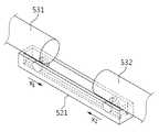
도 2는 도 1에서 설명된 착용형 보조 장치를 도시하는 평면도이다. 도 2를 참조하면, 착용형 보조 장치는 사용자의 신체 일 부분에 착용될 수 있다. 지지부(220)는 지정된 타겟 부위(210)에 접촉되며 사용자를 지지할 수 있다. 예시적으로 착용형 보조 장치가 고관절(hip joint) 보조 장치로 구현되는 경우에, 지지부(220)는 사용자의 등을 지지할 수 있다. 또한, 착용형 보조 장치가 무릎 보조 장치로 구현되는 경우에, 지지부(220)는 사용자의 무릎을 지지할 수 있다. 마찬가지로, 착용형 보조 장치가 팔꿈치 보조 장치로 구현되는 경우, 지지부(220)는 사용자의 팔꿈치를 지지할 수 있다.FIG. 2 is a plan view illustrating the wearable auxiliary device described in FIG. 1 . Referring to FIG. 2 , the wearable auxiliary device may be worn on a part of a user's body. The
착용형 보조 장치는 지지부(220)를 중심으로 하여 사용자의 제1 방향 및 제2 방향 각각에서 보조하는 힘(assistance power)을 제공한다. 제1 방향에서, 제1 구동부(231)는 제1 프레임(232)을 통하여 사용자에게 제1 힘을 전달할 수 있다. 제1 구동부(231)는 X 축을 중심으로 하여 피치 방향(pitch direction)의 회전력을 제1 힘으로서 생성할 수 있다. 마찬가지로, 제2 구동부(241)는 제2 프레임(242)을 통하여 사용자에게 제2 힘을 전달할 수 있다. 제2 구동부(241)도 X 축을 중심으로 하여 피치 방향의 회전력을 제2 힘으로서 생성할 수 있다. 착용형 보조 장치가 고관절 보조 장치로 구현되는 경우에, 피치 방향의 제1 힘 및 제2 힘이 사용자에게 제공되며 사용자의 보행 동작이 보조될 수 있다.The wearable assistive device provides assistance power in each of the user's first and second directions with the
제1 방향의 제1 착용부(233)와 제2 방향의 제2 착용부(243)는 지지부(220)를 중심으로 각각의 프레임(232, 242)들에게 교차 연결될 수 있다. 보다 구체적으로, 제1 착용부(233)는 제2 방향에 존재하는 제2 프레임(242)에 연결된다. 또한, 제1 착용부(233)는 제1 방향으로부터 당겨지고, 제2 프레임(242)을 X2 방향으로 이동시켜 타겟 부위(210)에 밀착시킬 수 있다. 제1 착용부(233)의 일단(234)은 제2 프레임(242)에 연결될 수 있다. 마찬가지로, 제2 착용부(243)는 제1 방향에 존재하는 제1 프레임(232)에 연결된다. 제2 착용부(243)는 제2 방향으로부터 당겨지고, 제1 프레임(232)을 X1 방향으로 이동시켜 타겟 부위(210)에 밀착시킬 수 있다. 제2 착용부(243)의 일단(244)은 제1 프레임(232)에 연결될 수 있다.The first wearing
또한, 제1 프레임(232)은 제1 착용부(233)가 통과하는 제1 중공부(235)를 포함한다. 제1 중공부(235)는 제1 착용부(233)가 제2 프레임(242)에 당김 힘을 전달하기 위해 통과하는 복수의 홀(hole)을 나타낸다. 제1 착용부(233)는 제1 중공부(235)를 통과하여 제2 프레임(242)을 이동시키는 힘을 전달할 수 있다. 마찬가지로, 제2 프레임(242)은 제2 착용부(243)가 통과하는 제2 중공부(245)를 포함한다. 제2 중공부(245)는 제2 착용부(243)가 제1 프레임(232)에 당김 힘을 전달하기 위해 통과하는 복수의 홀을 나타낸다. 제2 착용부(243)는 제2 중공부(245)를 통과하여 제1 프레임(232)을 이동시키는 힘을 전달할 수 있다.In addition, the
본 실시예에 따른 착용형 보조 장치는 교차 연결된 제1 착용부(233) 및 제2 착용부(243)를 통해 제1 프레임(232)과 제2 프레임(242)을 지정된 타겟 부위(210)를 향하여 이동시킬 수 있다. 또한, 제1 프레임(232) 및 제2 프레임(242) 각각이 이동되는 방향(X1 방향 또는 X2 방향)은 구동부들(231, 241)이 회전력을 생성하는 피치 방향과 수직(orthogonal)인 방향일 수 있다. 그에 따라, 본 실시예에 따른 착용형 보조 장치는 구동부(231, 241)가 생성하는 힘에 의해서는 프레임들(232, 242)의 위치가 변하지 않고 고정된다.In the wearable auxiliary device according to the present embodiment, the
도 3은 다른 일실시예에 따른 착용형 보조 장치의 개략적인 구성을 도시하는 블록도이다. 도 3을 참조하면, 사용자의 고관절에 착용되어 보행 동작을 보조하는 착용형 보조 장치(300)가 도시된다. 착용형 보조 장치(300)는 등 지지부(310), 체결부(320), 제1 구동부(331), 제1 허리 프레임(332), 제1 허리 착용부(333), 제1 가이드부(334), 제1 허벅지 프레임(335), 제1 허벅지 착용부(336), 제2 구동부(341), 제2 허리 프레임(342), 제2 허리 착용부(343), 제2 가이드부(344), 제2 허벅지 프레임(345) 및 제2 허벅지 착용부(346)를 포함할 수 있다.3 is a block diagram showing a schematic configuration of a wearable auxiliary device according to another embodiment. Referring to FIG. 3 , a
등 지지부(310)는 사용자의 등에 접촉되며 사용자를 지지할 수 있다. 등 지지부(310)는 제1 허리 프레임(332) 및 제2 허리 프레임(342)으로부터 전달되는 힘을 사용자에게 전달할 수 있다.The
제1 구동부(331) 및 제2 구동부(341)는 사용자를 보조하는 힘을 생성하고, 생성된 힘을 출력할 수 있다. 구체적으로, 제1 구동부(331)는 사용자의 오른쪽 방향에서 제1 힘을 생성하여, 사용자의 오른 다리의 보행을 보조할 수 있다. 또한, 제2 구동부(341)는 사용자의 왼쪽 방향에서 제2 힘을 생성하여, 사용자의 왼쪽 다리의 보행을 보조할 수 있다.The
제1 허리 프레임(332) 및 제2 허리 프레임(342)은 각각의 구동부들(331, 341)을 고정하고, 각각의 구동부들(331, 341)이 생성하는 힘을 등 지지부(310)로 전달할 수 있다. 예시적으로, 제1 허리 프레임(332) 및 제2 허리 프레임(342)은 리지드(rigid)한 프레임으로 구현될 수 있다. 보다 구체적으로, 제1 허리 프레임(332)은 사용자의 오른쪽 방향에서 사용자를 착용형 보조 장치(300)에 밀착시킬 수 있다. 또한, 제2 허리 프레임(342)은 사용자의 왼쪽 방향에서 사용자를 착용형 보조 장치(300)에 밀착시킬 수 있다.The
제1 허리 착용부(333) 및 제2 허리 착용부(343)는 사용자의 허리를 감싸는 방향으로 구현될 수 있다. 예시적으로, 그러나 한정되지 않게 제1 허리 착용부(333) 및 제2 허리 착용부(343)는 벨트, 고무줄, 스트링, 와이어 또는 체인과 같은 너비 방향 부재로 구현될 수 있다. 제1 허리 착용부(333) 및 제2 허리 착용부(343)는 등 지지부(310)와 각각의 허리 프레임들(332, 342)을 사용자 신체에 밀착시켜 고정시킬 수 있다.The first
제1 허리 착용부(333)의 일단과 제2 허리 착용부(343)의 일단은 체결부(320)를 통해 체결되어 고정된다. 보다 구체적으로, 제1 허리 착용부(333)의 일단 및 제2 허리 착용부(343)의 일단은 탈착 가능한 상태로서 체결될 수 있다. 예시적으로, 체결부(320)는 버클(buckle)이나 밸크로 형태로 구현될 수 있다. 이는 이해를 돕기 위한 예시적 기재일 뿐, 다른 실시예를 제한하거나 한정하는 것으로 해석되어서는 안될 것이다.One end of the first
제1 허리 착용부(333)의 타단은 제2 가이드부(344)를 통해 제2 허리 프레임(342)과 연결될 수 있다. 또한, 제2 허리 착용부(343)의 타단은 제1 가이드부(334)를 통해 제1 허리 프레임(332)과 연결될 수 있다. 본 실시예에서는 제1 허리 착용부(333) 및 제2 허리 착용부(343)가 각각의 가이드부(334, 344)를 통해 허리 프레임들(332, 342)과 연결되는 경우가 설명되나, 제1 허리 착용부(333) 및 제2 허리 착용부(343)들이 하나의 가이드부를 통해 허리 프레임들(332, 342)과 연결되는 실시예 또한 구현 가능할 것이다.The other end of the first
각각의 가이드부(334, 344)는 제1 허리 프레임(332)과 제2 허리 프레임(342)이 미리 지정된 방향으로 이동하도록 유도할 수 있다. 일실시예로서, 각각의 가이드부(334, 344)는 제1 허리 프레임(332)과 제2 허리 프레임(342)이 선형 이동되도록 유도할 수 있다. 구체적으로, 각각의 가이드부(334, 344)는 제1 허리 프레임(332) 및 제2 허리 프레임(342)이 사용자의 허리 폭 방향으로 자유롭게 움직일 수 있도록 가이드할 수 있다. 가이드부(334, 344)에 대한 구체적 구현 예시는 이하에서 추가될 도면과 함께 더욱 자세히 설명될 것이다.Each of the
제1 허벅지 프레임(335)은 사용자의 오른쪽 허벅지에 접촉되며, 제1 구동부(331)로부터 출력되는 힘을 오른쪽 허벅지에 전달할 수 있다. 마찬가지로, 제2 허벅지 프레임(345)은 사용자의 왼쪽 허벅지에 접촉되며, 제2 구동부(341)로부터 출력되는 힘을 왼쪽 허벅지에 전달할 수 있다.The first thigh frame 335 is in contact with the user's right thigh, and can transfer the force output from the
제1 허벅지 착용부(336) 및 제2 허벅지 착용부(346) 각각은 허벅지 프레임들(335, 345)로부터 전달되는 힘을 사용자의 허벅지에 전달하는 역할을 수행한다.Each of the first
본 실시예에서 설명되는 착용형 보조 장치(300)는 제1 가이드부(334)를 통해 제1 허리 프레임(332)이 오른쪽 방향에서 사용자에게 밀착되며, 제2 가이드부(344)를 통해 제2 허리 프레임(342)이 왼쪽 방향에서 사용자에게 밀착될 수 있다. 착용형 보조 장치(300)는 구동부들(331, 341)이 생성하는 회전력과 직교하는 방향으로 허리 프레임들(332, 342)의 이동이 가이드 될 수 있어, 구동부(331, 341)들의 회전축을 일정하게 고정할 수 있다.In the wearable
도 4는 도 3에서 설명된 착용형 보조 장치의 동작 방법을 간략히 설명하는 흐름도이다. 단계(411)에서는 제1 허리 착용부에 당김 힘이 작용할 수 있다. 보다 구체적으로, 제1 허리 착용부는 오른쪽 방향에서 사용자에 의해 당겨질 수 있다. 다른 일실시예로서, 제1 허리 착용부는 착용형 보조 장치의 사용자가 아닌, 사용자의 보호자에 의해 오른쪽 방향에서 당겨질 수 있다. 단계(412)에서는 제2 허리 프레임이 지정된 제1 방향으로 이동될 수 있다. 제1 방향은 제1 허리 착용부가 당겨지는 오른쪽 방향일 수 있다.FIG. 4 is a flowchart briefly explaining a method of operating the wearable assistive device described in FIG. 3 . In
또한, 단계(421)에서는 제2 허리 착용부에 당김 힘이 작용할 수 있다. 제2 허리 착용부는 왼쪽 방향에서 사용자 또는 사용자의 보호자에 의해 당겨질 수 있다. 이어서, 단계(422)에서는 제1 허리 프레임이 지정된 제2 방향으로 이동될 수 있다. 제2 방향은 제2 허리 착용부가 당겨지는 왼쪽 방향일 수 있다.Also, in
본 실시예에서는 단계(411)가 설명된 이후에 단계(421)가 설명되나 이는 이해를 돕기 위한 예시적 기재 일 뿐, 다른 실시예를 제한하거나 한정하는 것으로 해석되어서는 안될 것이다. 이를테면, 왼쪽에 존재하는 제2 허리 착용부가 우선적으로 당겨진 후에 오른쪽에 존재하는 제1 허리 착용부가 당겨질 수도 있을 것이다. 또한, 제1 허리 착용부와 제2 허리 착용부가 동시에 당겨지는 실시예도 착용형 보조 장치의 동작 방법 중 하나일 수 있다.In this embodiment,
단계(430)에서는 제1 허리 프레임 및 제2 허리 프레임들이 사용자의 타겟 부위에 밀착될 수 있다. 이 경우에, 제1 허리 착용부와 제2 허리 착용부는 서로 체결될 수 있다. 예시적으로, 제1 허리 착용부의 일단에 형성된 홀(hole)과 제2 허리 착용부의 일단에 형성된 연결핀(pin)을 통해 제1 허리 착용부 및 제2 허리 착용부는 서로 체결될 수 있다.In
제1 허리 착용부와 제2 허리 착용부가 서로 체결된 경우, 제1 허리 프레임과 제2 허리 프레임은 지정된 타겟 부위에서 더 이상 이동되지 않고 고정될 수 있다. 보다 구체적으로, 각각의 허리 프레임들은 안 쪽 방향으로는 사용자의 신체와 밀착되어 이동이 불가하고, 바깥 쪽 방향으로는 제1 허리 착용부와 제2 허리 착용부를 고정하는 체결부에 의해 이동이 방지될 수 있다.When the first waist wear part and the second waist wear part are fastened to each other, the first waist frame and the second waist frame may be fixed without moving any further in the designated target region. More specifically, each of the waist frames is in close contact with the user's body in an inward direction so that movement is impossible, and movement is prevented in an outward direction by a fastening portion fixing the first waist wearing part and the second waist wearing part. It can be.
본 실시예에 따른 착용형 보조 장치는 착용 시에는 힘을 전달하는 허리 프레임들이 사용자 신체의 크기에 맞게 이동되어 사용자에게 피팅되며, 허리 착용부들이 체결되어 착용이 완료된 경우에는 더 이상 이동되지 않고 지정된 타겟 부위에 고정될 수 있어 구동부가 안정적으로 보조력을 전달할 수 있다.When the wearable assistive device according to the present embodiment is worn, the waist frames that transmit force are moved to fit the size of the user's body and fitted to the user. Since it can be fixed to the target area, the drive unit can stably deliver the assisting force.
도 5a는 일실시예에 따른 가이드부의 동작을 설명하는 평면도이다. 도 5a를 참조하면, 가이드부를 포함하는 착용형 보조 장치의 평면도가 도시된다. 도 5a에서는 설명의 편의를 위해 지지부(510)가 사용자의 등(back)에 밀착된 실시예에 대해 설명 하나, 지지부(510)가 팔꿈치 또는 무릎과 같은 다른 신체 부위에 밀착된 경우에도 가이드부가 동작할 수 있다는 것은 기술 분야의 전문가에게는 자명한 사실일 것이다.5A is a plan view illustrating an operation of a guide unit according to an exemplary embodiment. Referring to FIG. 5A , a plan view of a wearable auxiliary device including a guide unit is shown. 5A describes an embodiment in which the
지지부(510)의 상단에는 제1 프레임(531)과 제2 프레임(532) 각각이 지정된 방향으로 이동되도록 유도하는 가이드부(520)가 배치될 수 있다. 예시적으로 지지부(510)가 사용자의 등에 밀착되면, 가이드부(520)는 각각의 프레임(531, 532)들이 사용자의 허리 폭 방향으로 이동되도록 유도한다.A
보다 구체적으로, 사용자 또는 사용자의 보호자로부터 제1 착용부에 대해 제1 당김 힘 F1이 적용(541)되는 경우, 제2 프레임(532)에 대해서는 제2 당김 힘 F2이 적용(542)될 것이다. 이에 따라, 제2 프레임(532)은 허리 폭 방향인 X2 방향으로 이동될 수 있다. 구체적으로, 제2 프레임(532)은 가이드부(520)가 제공하는 이동 경로를 통해 지정된 X2 방향으로 이동(542)한다. 마찬가지로, 도 5a에 도시되지 않았지만, 제2 착용부에 대해 당김 힘이 적용되는 경우에도 제1 프레임(531) 역시 사용자의 허리 폭 방향인 X1 방향으로 이동 될 수 있다는 것은 기술 분야의 전문가에게는 자명한 사실일 것이다. 이하에서는, 가이드부(520)의 몇 가지 구현 예시들이 도면과 함께 설명될 것이다.More specifically, when a first pulling force F1 is applied (541) to the first worn part by the user or the user's guardian, a second pulling force F2 is applied (542) to the
도 5b는 일실시예에 따른 가이드부의 사시도이다. 가이드부(521)는 미리 지정된 방향을 따라 연장되는 레일(rail) 형태로 구현될 수 있다. 미리 지정된 방향은 구동부가 생성하는 회전력의 축 방향(X 축 방향)을 나타낼 수 있다. 제1 프레임(531) 및 제2 프레임(532) 중 적어도 하나는 가이드부(521)에 포함되는 레일을 따라 이동할 수 있다. 제1 프레임(531) 및 제2 프레임(532)의 하단에는 레일 상에서 이동하기 위한 바퀴가 포함될 수 있다.5B is a perspective view of a guide unit according to an embodiment. The
제1 착용부에 적용되는 당김 힘에 의해 제2 프레임(532)은 레일을 따라 X2 방향으로 이동될 수 있다. 또한, 제2 착용부에 적용되는 당김 힘에 의해 제1 프레임(531)은 레일을 따라 X1 방향으로 이동될 수 있다.The
도 5c는 다른 일실시예에 따른 가이드부의 사시도이다. 가이드부(522)는 미리 지정된 방향을 따라 이동 경로를 형성하는 가이드 블록 형태로 구현될 수 있다. 미리 지정된 방향은 구동부가 생성하는 회전력의 축 방향(X 축 방향)을 나타낼 수 있다. 제1 프레임(531) 및 제2 프레임(532) 중 적어도 하나는 가이드부(522)가 제공하는 이동 경로를 따라 이동할 수 있다.5C is a perspective view of a guide unit according to another embodiment. The
마찬가지로, 제1 착용부에 적용되는 당김 힘에 의해 제2 프레임(532)은 이동 경로를 따라 X2 방향으로 이동될 수 있다. 또한, 제2 착용부에 적용되는 당김 힘에 의해 제1 프레임(531)은 이동 경로를 따라 X1 방향으로 이동될 수 있다.Similarly, the
도 5b 및 도 5c에서는 가이드부(520)에 대한 실시예들이 개시되나, 이는 이해를 돕기 위한 예시적 기재일 뿐, 다른 실시예의 범위를 제한하거나 한정하는 것으로 해석되어서는 안 될 것이다.Although embodiments of the
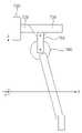
도 6은 다른 일실시예에 따른 착용형 보조 장치의 개략적인 구성을 도시하는 예시도이다. 도 6을 참조하면, 착용형 보조 장치는 프레임(610), 가이드부(620) 및 구동부(630)를 포함할 수 있다. 프레임(610)은 구동부(630)가 생성하는 힘을 지지부로 전달할 수 있다. 가이드부(620)는 프레임(610)에 연결되며, 구동부(630)가 미리 지정된 방향으로 선형 이동되도록 유도할 수 있다. 보다 구체적으로, 가이드부(620)는 프레임(610)과 구동부(630) 사이에 배치될 수 있다. 구동부(630)는 가이드부(620)를 통해 제1 위치(631)로부터 제2 위치(632)까지 자유도를 가지고 움직일 수 있다. 보다 구체적으로, 착용형 보조 장치는 사용자 신체의 크기에 따라 구동부(630)의 위치가 조정될 수 있다. 본 실시예에 따른 착용형 보조 장치는 사용자의 허리 폭, 엉덩이 높이, 배 두께, 다리 두께 등과 같은 다양한 신체 크기에 대응하여 구동부(630)가 출력하는 회전력의 축 방향이 사용자 관절(joint)에 일치하게 조정될 수 있다. 이하에서는, 보다 구체적인 도면과 함께 구동부(630)의 위치가 가이드부(620)를 따라 조절되는 과정이 설명된다.6 is an exemplary view showing a schematic configuration of a wearable auxiliary device according to another embodiment. Referring to FIG. 6 , the wearable auxiliary device may include a
도 7a는 일실시예에 따라 구동부의 위치가 조정되는 착용형 보조 장치의 측면도이다. 도 7a를 참조하면, 사용자의 고관절에 착용되는 착용형 보조 장치가 도시된다. 착용형 보조 장치는 등 지지부(710), 허리 프레임(720), 허리 착용부(730), 구동부(740) 및 제1 가이드부(751)를 포함할 수 있다. 등 지지부(710), 허리 프레임(720), 허리 착용부(730) 및 구동부(740)에 대해서는 앞서 도 3과 함께 기재된 설명이 그대로 적용될 수 있어, 중복되는 설명은 생략하기로 한다.7A is a side view of a wearable auxiliary device in which a position of a driving unit is adjusted according to an exemplary embodiment. Referring to FIG. 7A , a wearable auxiliary device worn on a user's hip joint is shown. The wearable assistive device may include a
제1 가이드부(751)는 허리 프레임(720)에 연결되며, 구동부(740)가 미리 지정된 방향으로 선형 이동되도록 유도할 수 있다. 예시적으로, 미리 지정된 방향은 사용자 신체를 기준으로 Z 축 방향(위, 아래 방향)을 나타낼 수 있다. 구동부(740)는 제1 가이드부(751)를 통해 위 쪽 방향에서 아래 쪽 방향으로 이동의 자유도를 가질 수 있다. 이에 따라, 착용형 보조 장치는 사용자의 신체 크기에 대응하여 사용자의 높이 방향으로 구동부의 위치를 조정할 수 있다.The
도 7b는 다른 일실시예에 따라 구동부의 위치가 조정되는 착용형 보조 장치의 측면도이다. 도 7b의 착용형 보조 장치는 등 지지부(710), 허리 프레임(720), 허리 착용부(730), 구동부(740) 및 제2 가이드부(752)를 포함할 수 있다.7B is a side view of a wearable auxiliary device in which a position of a driving unit is adjusted according to another embodiment. The wearable assistive device of FIG. 7B may include a
제2 가이드부(752)는 허리 프레임(720)에 연결되며, 구동부가 미리 지정된 방향으로 선형 이동되도록 유도할 수 있다. 예시적으로, 미리 지정된 방향은 사용자 신체를 기준으로 Y 축 방향(앞, 뒤 방향)을 나타낼 수 있다. 구동부(740)는 제2 가이드부(752)를 통해 앞 쪽 방향에서 뒤 쪽 방향으로의 이동의 자유도를 가질 수 있다. 이에 따라, 착용형 보조 장치는 사용자의 엉덩이 두께 또는 허벅지 두께 등에 대응하여 사용자의 앞뒤 방향으로 구동부의 위치를 조정할 수 있다.The
도 7c는 또 다른 일실시예에 따라 구동부의 위치가 조정되는 착용형 보조 장치의 측면도이다. 도 7c의 착용형 보조 장치는 등 지지부(710), 허리 프레임(720), 허리 착용부(730), 구동부(740) 및 제3 가이드부(753)를 포함할 수 있다.7C is a side view of a wearable auxiliary device in which a position of a driving unit is adjusted according to another embodiment. The wearable assistive device of FIG. 7C may include a
제3 가이드부(753)는 허리 프레임에 연결되며, 구동부가 미리 지정된 방향으로 선형 이동되도록 유도할 수 있다. 예시적으로, 미리 지정된 방향은 구동부(740)에 의해 생성되는 회전력의 축 방향과 수직한 평면에 존재하는 임의의 방향을 나타낼 수 있다. 구동부(740)는 사용자의 신체 크기에 대응하여 제3 가이드부(753)를 통해 등 지지부(710)의 중심 방향으로부터 구동부(740)의 중심을 지나는 방향으로 1 자유도를 가질 수 있다. 이에 따라, 착용형 보조 장치는 사용자의 신체 크기에 대응하여 Y-Z 평면 상에서 구동부의 위치를 조정할 수 있다.The
도 8a는 일실시예에 따라 구동부에 연결되는 가이드부의 동작을 설명하는 예시도이다. 도 8a를 참조하면, 가이드부는 지정된 방향을 따라 연장되는 레일(821), 구동부(810)에 접촉되며 레일(821)을 따라 이동하는 이동 부재(822), 레일(821) 상에서 소정 간격으로 배치되는 적어도 하나의 홀(823) 및 이동 부재(822)와 연결되며 적어도 하나의 홀(823) 중 어느 하나에 삽입되는 핀(824)을 포함할 수 있다.8A is an exemplary diagram illustrating an operation of a guide unit connected to a driving unit according to an exemplary embodiment. Referring to FIG. 8A, the guide unit is disposed at predetermined intervals on a
이동 부재(822)는 레일(821)에 접촉되며 회동하는 바퀴를 포함하고, 이동 부재(822)의 상단에는 구동부(810)가 연결될 수 있다. 착용형 보조 장치는 레일(821)을 따라 이동 부재(822)를 이동시켜 구동부(810)의 위치를 조정할 수 있다.The moving
예시적으로, 가이드부의 레일(821)이 사용자의 높이 방향인 Z 축 방향을 따라 구현되는 실시예가 존재할 수 있다. 이 경우에, 가이드부와 구동부(810)는 이동의 자유도가 존재하는 연직 방향으로 중력을 받게 될 것이다. 그에 따라, 본 실시예의 착용형 보조 장치를 이용하는 사용자 또는 사용자의 보호자는 가이드부에 포함되는 핀(824)을 적어도 하나의 홀(823) 중 어느 하나에 삽입할 수 있다. 핀(824)이 적어도 하나의 홀(823)에 삽입됨에 따라, 착용형 보조 장치는 원하는 높이에서 구동부(810)를 고정할 수 있다. 이에 따라, 착용형 보조 장치는 사용자의 높이 방향으로도 구동부(810)의 위치를 정확하게 조정할 수 있다.Illustratively, there may be an embodiment in which the
도 8b는 다른 일실시예에 따라 구동부에 연결되는 가이드부의 동작을 설명하는 예시도이다. 도 8b를 참조하면, 가이드부는 미리 지정된 방향을 따라 이동 경로를 형성하는 가이드 블록(831), 구동부(810)와 연결되며 이동 경로를 따라 이동하는 이동 부재(832) 및 이동 경로 상에 배치되는 스토퍼(stopper)(833)를 포함할 수 있다. 이동 부재(832)는 가이드 블록(831)이 형성하는 이동 경로 내에 삽입되며, 상단 방향으로는 구동부(810)와 연결된 형태로서 구현될 수 있다. 이동 부재(832)는 가이드 블록(831) 내에서 이동하며 구동부(810)의 선형 이동을 유도할 수 있다.8B is an exemplary view illustrating an operation of a guide unit connected to a driving unit according to another embodiment. Referring to FIG. 8B, the guide unit includes a
가이드 블록(831)은 소정 간격으로 배치되는 복수의 홀을 포함할 수 있다. 스토퍼(833)는 복수의 홀 중 어느 하나에 삽입되며 구동부(810)를 지정된 위치에 고정 시킬 수 있다. 예시적으로, 스토퍼(833)는 나사 볼트(screw bolt) 형상으로 구현되며, 복수의 홀 중 어느 하나에 삽입되어 이동 경로 상으로의 이동 부재(832)의 이동을 저지할 수 있다The
착용형 보조 장치의 사용자 또는 사용자의 보호자는 스토퍼(833)를 복수의 홀 중 어느 하나에 삽입할 수 있다. 위와 같은 동작을 통해, 착용형 보조 장치는 사용자의 신체 크기에 따라 구동부(810)의 회전축을 고정시킬 수 있다A user of the wearable assistive device or a guardian of the user may insert the
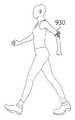
도 9a 내지 도 9c는 다양한 타겟 부위에 접촉되는 착용형 보조 장치의 실시예를 도시하는 예시도이다. 착용형 보조 장치는 사용자의 다양한 타겟 부위에 접촉되며, 사용자에게 보조하는 힘을 제공할 수 있다. 도 9a를 참조하면, 제1 착용형 보조 장치(910)가 고관절 보조 장치로 구현된 실시예가 도시된다. 제1 착용형 보조 장치(910)는 등 지지부를 포함하여 허리 폭 방향으로 사용자와 밀착되는 프레임을 포함할 수 있다.9A to 9C are exemplary views illustrating embodiments of a wearable auxiliary device in contact with various target areas. The wearable assistive device may come into contact with various target parts of the user and provide assistive power to the user. Referring to FIG. 9A , an embodiment in which the first wearable
또한, 도 9b를 참조하면, 제2 착용형 보조 장치(920)가 무릎 보조 장치로 구현된 실시예가 도시된다. 제2 착용형 보조 장치(920)의 착용부는 무릎 보조 장치를 사용자의 무릎에 묶는 형태로 구현될 수 있다.Also, referring to FIG. 9B , an embodiment in which the second
마찬가지로, 도 9c를 참조하면, 제3 착용형 보조 장치(930)가 팔꿈치 보조 장치로 구현된 실시예가 도시된다. 또한, 제3 착용형 보조 장치(930)의 착용부는 팔꿈치 보조 장치를 사용자의 팔꿈치에 묶는 형태로 구현될 수 있다. 도 9b 및 도 9c는 이해를 돕기 위한 예시적 기재일 뿐, 본 실시예의 착용형 보조 장치는 사용자 신체의 다른 관절 움직임을 보조하는 장치로부터 구현될 수 있다.Similarly, referring to FIG. 9C , an embodiment in which the third wearable
이상에서 설명된 장치는 하드웨어 구성요소, 소프트웨어 구성요소, 및/또는 하드웨어 구성요소 및 소프트웨어 구성요소의 조합으로 구현될 수 있다. 예를 들어, 실시예들에서 설명된 장치 및 구성요소는, 예를 들어, 프로세서, 콘트롤러, ALU(arithmetic logic unit), 디지털 신호 프로세서(digital signal processor), 마이크로컴퓨터, FPA(field programmable array), PLU(programmable logic unit), 마이크로프로세서, 또는 명령(instruction)을 실행하고 응답할 수 있는 다른 어떠한 장치와 같이, 하나 이상의 범용 컴퓨터 또는 특수 목적 컴퓨터를 이용하여 구현될 수 있다. 처리 장치는 운영 체제(OS) 및 운영 체제 상에서 수행되는 하나 이상의 소프트웨어 애플리케이션을 수행할 수 있다. 또한, 처리 장치는 소프트웨어의 실행에 응답하여, 데이터를 접근, 저장, 조작, 처리 및 생성할 수도 있다. 이해의 편의를 위하여, 처리 장치는 하나가 사용되는 것으로 설명된 경우도 있지만, 해당 기술분야에서 통상의 지식을 가진 자는, 처리 장치가 복수 개의 처리 요소(processing element) 및/또는 복수 유형의 처리 요소를 포함할 수 있음을 알 수 있다. 예를 들어, 처리 장치는 복수 개의 프로세서 또는 하나의 프로세서 및 하나의 콘트롤러를 포함할 수 있다. 또한, 병렬 프로세서(parallel processor)와 같은, 다른 처리 구성(processing configuration)도 가능하다.The devices described above may be implemented as hardware components, software components, and/or a combination of hardware components and software components. For example, devices and components described in the embodiments may include, for example, a processor, a controller, an arithmetic logic unit (ALU), a digital signal processor, a microcomputer, a field programmable array (FPA), It may be implemented using one or more general purpose or special purpose computers, such as a programmable logic unit (PLU), microprocessor, or any other device capable of executing and responding to instructions. The processing device may run an operating system (OS) and one or more software applications running on the operating system. A processing device may also access, store, manipulate, process, and generate data in response to execution of software. For convenience of understanding, there are cases in which one processing device is used, but those skilled in the art will understand that the processing device includes a plurality of processing elements and/or a plurality of types of processing elements. It can be seen that it can include. For example, a processing device may include a plurality of processors or a processor and a controller. Other processing configurations are also possible, such as parallel processors.
소프트웨어는 컴퓨터 프로그램(computer program), 코드(code), 명령(instruction), 또는 이들 중 하나 이상의 조합을 포함할 수 있으며, 원하는 대로 동작하도록 처리 장치를 구성하거나 독립적으로 또는 결합적으로(collectively) 처리 장치를 명령할 수 있다. 소프트웨어 및/또는 데이터는, 처리 장치에 의하여 해석되거나 처리 장치에 명령 또는 데이터를 제공하기 위하여, 어떤 유형의 기계, 구성요소(component), 물리적 장치, 가상 장치(virtual equipment), 컴퓨터 저장 매체 또는 장치, 또는 전송되는 신호 파(signal wave)에 영구적으로, 또는 일시적으로 구체화(embody)될 수 있다. 소프트웨어는 네트워크로 연결된 컴퓨터 시스템 상에 분산되어서, 분산된 방법으로 저장되거나 실행될 수도 있다. 소프트웨어 및 데이터는 하나 이상의 컴퓨터 판독 가능 기록 매체에 저장될 수 있다.Software may include a computer program, code, instructions, or a combination of one or more of the foregoing, which configures a processing device to operate as desired or processes independently or collectively. The device can be commanded. Software and/or data may be any tangible machine, component, physical device, virtual equipment, computer storage medium or device, intended to be interpreted by or provide instructions or data to a processing device. , or may be permanently or temporarily embodied in a transmitted signal wave. Software may be distributed on networked computer systems and stored or executed in a distributed manner. Software and data may be stored on one or more computer readable media.
실시예에 따른 방법은 다양한 컴퓨터 수단을 통하여 수행될 수 있는 프로그램 명령 형태로 구현되어 컴퓨터 판독 가능 매체에 기록될 수 있다. 컴퓨터 판독 가능 매체는 프로그램 명령, 데이터 파일, 데이터 구조 등을 단독으로 또는 조합하여 포함할 수 있다. 매체에 기록되는 프로그램 명령은 실시예를 위하여 특별히 설계되고 구성된 것들이거나 컴퓨터 소프트웨어 당업자에게 공지되어 사용 가능한 것일 수도 있다. 컴퓨터 판독 가능 기록 매체의 예에는 하드 디스크, 플로피 디스크 및 자기 테이프와 같은 자기 매체(magnetic media), CD-ROM, DVD와 같은 광기록 매체(optical media), 플롭티컬 디스크(floptical disk)와 같은 자기-광 매체(magneto-optical media), 및 롬(ROM), 램(RAM), 플래시 메모리 등과 같은 프로그램 명령을 저장하고 수행하도록 특별히 구성된 하드웨어 장치가 포함된다. 프로그램 명령의 예에는 컴파일러에 의해 만들어지는 것과 같은 기계어 코드뿐만 아니라 인터프리터 등을 사용해서 컴퓨터에 의해서 실행될 수 있는 고급 언어 코드를 포함한다. 상기된 하드웨어 장치는 실시예의 동작을 수행하기 위해 하나 이상의 소프트웨어 모듈로서 작동하도록 구성될 수 있으며, 그 역도 마찬가지이다.The method according to the embodiment may be implemented in the form of program instructions that can be executed through various computer means and recorded on a computer readable medium. Computer readable media may include program instructions, data files, data structures, etc. alone or in combination. Program commands recorded on the medium may be specially designed and configured for the embodiment or may be known and usable to those skilled in computer software. Examples of computer-readable recording media include magnetic media such as hard disks, floppy disks and magnetic tapes, optical media such as CD-ROMs and DVDs, and magnetic media such as floptical disks. - includes hardware devices specially configured to store and execute program instructions, such as magneto-optical media, and ROM, RAM, flash memory, and the like. Examples of program instructions include high-level language codes that can be executed by a computer using an interpreter, as well as machine language codes such as those produced by a compiler. The hardware devices described above may be configured to operate as one or more software modules to perform the operations of the embodiments, and vice versa.
이상과 같이 실시예들이 비록 한정된 도면에 의해 설명되었으나, 해당 기술분야에서 통상의 지식을 가진 자라면 상기를 기초로 다양한 기술적 수정 및 변형을 적용할 수 있다. 예를 들어, 설명된 기술들이 설명된 방법과 다른 순서로 수행되거나, 및/또는 설명된 시스템, 구조, 장치, 회로 등의 구성요소들이 설명된 방법과 다른 형태로 결합 또는 조합되거나, 다른 구성요소 또는 균등물에 의하여 대치되거나 치환되더라도 적절한 결과가 달성될 수 있다.As described above, although the embodiments have been described with limited drawings, those skilled in the art can apply various technical modifications and variations based on the above. For example, the described techniques may be performed in an order different from the method described, and/or components of the described system, structure, device, circuit, etc. may be combined or combined in a different form than the method described, or other components may be used. Or even if it is replaced or substituted by equivalents, appropriate results can be achieved.
그러므로, 다른 구현들, 다른 실시예들 및 특허청구범위와 균등한 것들도 후술하는 특허청구범위의 범위에 속한다.Therefore, other implementations, other embodiments, and equivalents of the claims are within the scope of the following claims.
Claims (17)
Translated fromKorean제1 구동부에 의해 생성된 제1 힘(power)을 전달하는 제1 프레임;
제2 구동부에 의해 생성된 제2 힘을 전달하는 제2 프레임;
상기 제2 프레임에 연결되고, 당김 힘이 작용하는 경우 상기 제2 프레임을 상기 제1 프레임을 향하는 제1 방향으로 당겨 상기 제2 프레임을 상기 사용자에게 밀착시키는 제1 착용부; 및
상기 제1 프레임에 연결되고, 당김 힘이 작용하는 경우 상기 제1 프레임을 상기 제2 프레임을 향하는 제2 방향으로 당겨 상기 제1 프레임을 상기 사용자에게 밀착시키는 제2 착용부를 포함하고,
상기 제1 착용부가 당겨지면 상기 제2 프레임이 이동되고, 상기 제2 착용부가 당겨지면 상기 제1 프레임이 이동되는 교차 연결 구조를 가지는,
착용형 보조 장치.
In the wearable auxiliary device worn by the user,
A first frame transmitting a first force (power) generated by the first driving unit;
a second frame transmitting a second force generated by the second driving unit;
a first wearer connected to the second frame and bringing the second frame into close contact with the user by pulling the second frame in a first direction toward the first frame when a pulling force is applied; and
A second wearing part connected to the first frame and bringing the first frame into close contact with the user by pulling the first frame in a second direction toward the second frame when a pulling force is applied;
Having a cross-connection structure in which the second frame is moved when the first wearing part is pulled and the first frame is moved when the second wearing part is pulled,
wearable assistive device.
상기 제1 힘을 생성하는 제1 구동부;
상기 제2 힘을 생성하는 제2 구동부; 및
지정된 타겟 부위에 접촉되며 상기 사용자를 지지하는 지지부
를 더 포함하는 착용형 보조 장치.
According to claim 1,
a first driving unit generating the first force;
a second driving unit generating the second force; and
A support unit that comes into contact with a designated target area and supports the user
A wearable assistive device further comprising a.
상기 제1 프레임을 상기 제2 방향으로 이동하도록 유도하거나 또는 상기 제2 프레임을 상기 제1 방향으로 이동하도록 유도하는 가이드부
를 더 포함하는 착용형 보조 장치.
According to claim 1,
A guide unit for inducing the first frame to move in the second direction or for inducing the second frame to move in the first direction.
A wearable assistive device further comprising a.
상기 가이드부는,
상기 제1 프레임 및 상기 제2 프레임 중 적어도 하나가 선형 이동되도록 유도하는,
착용형 보조 장치.
According to claim 3,
The guide part,
Inducing at least one of the first frame and the second frame to move linearly,
wearable assistive device.
상기 가이드부는, 레일(rail)을 포함하고,
상기 제1 프레임 및 상기 제2 프레임 중 적어도 하나는, 상기 레일을 따라 이동하는,
착용형 보조 장치.
According to claim 3,
The guide part includes a rail,
At least one of the first frame and the second frame moves along the rail,
wearable assistive device.
상기 가이드부는, 이동 경로를 형성하는 가이드 블록을 포함하고,
상기 제1 프레임 및 상기 제2 프레임 중 적어도 하나는, 상기 이동 경로를 따라 이동하는,
착용형 보조 장치.
According to claim 3,
The guide unit includes a guide block forming a movement path,
At least one of the first frame and the second frame moves along the movement path,
wearable assistive device.
상기 제1 착용부와 상기 제2 착용부를 고정하는 체결부
를 더 포함하고,
상기 제1 착용부와 상기 제2 착용부가 체결된 경우에, 상기 제1 프레임 및 상기 제2 프레임은 지정된 타겟 부위에 고정되는,
착용형 보조 장치.
According to claim 1,
Fastening part fixing the first wearing part and the second wearing part
Including more,
When the first wearing part and the second wearing part are fastened, the first frame and the second frame are fixed to a designated target part.
wearable assistive device.
상기 제1 프레임은, 상기 제2 착용부의 일단과 연결되고,
상기 제2 프레임은, 상기 제1 착용부의 일단과 연결되는,
착용형 보조 장치.
According to claim 1,
The first frame is connected to one end of the second wearing part,
The second frame is connected to one end of the first wearing part,
wearable assistive device.
상기 제1 프레임은, 상기 제1 착용부가 통과하는 제1 중공부를 포함하고,
상기 제2 프레임은, 상기 제2 착용부가 통과하는 제2 중공부를 포함하는,
착용형 보조 장치.
According to claim 9,
The first frame includes a first hollow part through which the first wearing part passes,
The second frame includes a second hollow part through which the second wearing part passes.
wearable assistive device.
상기 가이드부는,
상기 제1 구동부 및 상기 제2 구동부 중 적어도 하나와 연결되고, 상기 레일을 따라 이동하는 이동 부재;
상기 레일 상에서 소정 간격으로 배치되는 적어도 하나의 홀(hole); 및
상기 이동 부재와 연결되어 상기 적어도 하나의 홀 중 어느 하나에 삽입되어 상기 구동부를 고정하는 핀(pin)
을 더 포함하는 착용형 보조 장치.
According to claim 5,
The guide part,
a moving member connected to at least one of the first driving unit and the second driving unit and moving along the rail;
at least one hole disposed on the rail at predetermined intervals; and
A pin connected to the moving member and inserted into any one of the at least one hole to fix the driving unit
A wearable assistive device further comprising a.
상기 가이드부는,
상기 제1 구동부 및 상기 제2 구동부 중 적어도 하나와 연결되고, 상기 이동 경로를 따라 이동하는 이동 부재; 및
상기 이동 경로 상에 배치되는 스토퍼(stopper)
를 더 포함하는 착용형 보조 장치.
According to claim 6,
The guide part,
a moving member connected to at least one of the first driving unit and the second driving unit and moving along the moving path; and
A stopper disposed on the movement path
A wearable assistive device further comprising a.
상기 가이드 블록은, 소정 간격으로 배치되는 복수의 홀(hole)들을 포함하고,
상기 스토퍼는, 상기 복수의 홀들 중 어느 하나에 삽입되어 상기 제1 구동부 및 상기 제2 구동부 중 적어도 하나를 고정시키는,
착용형 보조 장치.According to claim 16,
The guide block includes a plurality of holes disposed at predetermined intervals,
The stopper is inserted into any one of the plurality of holes to fix at least one of the first driving unit and the second driving unit.
wearable assistive device.
Priority Applications (2)
| Application Number | Priority Date | Filing Date | Title |
|---|---|---|---|
| KR1020170102103AKR102473884B1 (en) | 2017-08-11 | 2017-08-11 | Wearable apparatus for assistance and operating method thereof |
| US15/854,173US11510839B2 (en) | 2017-08-11 | 2017-12-26 | Wearable apparatus for assistance and operating method thereof |
Applications Claiming Priority (1)
| Application Number | Priority Date | Filing Date | Title |
|---|---|---|---|
| KR1020170102103AKR102473884B1 (en) | 2017-08-11 | 2017-08-11 | Wearable apparatus for assistance and operating method thereof |
Publications (2)
| Publication Number | Publication Date |
|---|---|
| KR20190017358A KR20190017358A (en) | 2019-02-20 |
| KR102473884B1true KR102473884B1 (en) | 2022-12-06 |
Family
ID=65274421
Family Applications (1)
| Application Number | Title | Priority Date | Filing Date |
|---|---|---|---|
| KR1020170102103AActiveKR102473884B1 (en) | 2017-08-11 | 2017-08-11 | Wearable apparatus for assistance and operating method thereof |
Country Status (2)
| Country | Link |
|---|---|
| US (1) | US11510839B2 (en) |
| KR (1) | KR102473884B1 (en) |
Citations (3)
| Publication number | Priority date | Publication date | Assignee | Title |
|---|---|---|---|---|
| KR100966751B1 (en)* | 2008-10-22 | 2010-06-29 | 서강대학교산학협력단 | Intelligent muscle and walking aid robot |
| US20110168485A1 (en) | 2010-01-11 | 2011-07-14 | Honda Motor Co., Ltd. | Belt buckle device |
| KR101233649B1 (en)* | 2011-10-26 | 2013-02-15 | 한양대학교 에리카산학협력단 | Wearable robot to assist muscular strength |
Family Cites Families (12)
| Publication number | Priority date | Publication date | Assignee | Title |
|---|---|---|---|---|
| US5893367A (en) | 1997-03-27 | 1999-04-13 | Dubats; David Edward | Therapeutic gait harness and pelvic support system |
| JP4326580B2 (en) | 2007-09-25 | 2009-09-09 | 本田技研工業株式会社 | Walking assistance device thigh orthosis |
| JP2009284919A (en) | 2008-05-27 | 2009-12-10 | Honda Motor Co Ltd | Hip fitting device |
| JP5081740B2 (en) | 2008-06-19 | 2012-11-28 | 本田技研工業株式会社 | Lumbar orthosis for walking assist devices |
| JP5161036B2 (en) | 2008-11-06 | 2013-03-13 | 本田技研工業株式会社 | Walking assist device |
| JP2013070784A (en) | 2011-09-27 | 2013-04-22 | Equos Research Co Ltd | Walking aid device |
| JP5979703B2 (en) | 2012-02-23 | 2016-08-31 | 国立大学法人 筑波大学 | Wearable motion assist device |
| US9662262B2 (en)* | 2013-05-06 | 2017-05-30 | Springactive, Inc. | Joint torque augmentation system and method for gait assistance |
| KR102158131B1 (en)* | 2014-05-23 | 2020-09-21 | 삼성전자주식회사 | Walking assist apparatus |
| JP6270663B2 (en) | 2014-08-20 | 2018-01-31 | 本田技研工業株式会社 | Walking assist device |
| JP2016067899A (en) | 2014-09-29 | 2016-05-09 | Cyberdyne株式会社 | Brake device for wearable electromechanical device |
| US10835443B2 (en)* | 2017-11-13 | 2020-11-17 | Free Bionics Taiwan Inc. | Exoskeleton robot |
- 2017
- 2017-08-11KRKR1020170102103Apatent/KR102473884B1/enactiveActive
- 2017-12-26USUS15/854,173patent/US11510839B2/enactiveActive
Patent Citations (3)
| Publication number | Priority date | Publication date | Assignee | Title |
|---|---|---|---|---|
| KR100966751B1 (en)* | 2008-10-22 | 2010-06-29 | 서강대학교산학협력단 | Intelligent muscle and walking aid robot |
| US20110168485A1 (en) | 2010-01-11 | 2011-07-14 | Honda Motor Co., Ltd. | Belt buckle device |
| KR101233649B1 (en)* | 2011-10-26 | 2013-02-15 | 한양대학교 에리카산학협력단 | Wearable robot to assist muscular strength |
Also Published As
| Publication number | Publication date |
|---|---|
| US20190046386A1 (en) | 2019-02-14 |
| US11510839B2 (en) | 2022-11-29 |
| KR20190017358A (en) | 2019-02-20 |
Similar Documents
| Publication | Publication Date | Title |
|---|---|---|
| CN113081700B (en) | Pelvis fixing device and exercise assisting apparatus including the same | |
| Quintero et al. | A method for the autonomous control of lower limb exoskeletons for persons with paraplegia | |
| US11938050B2 (en) | Torque control methods and devices for powered orthosis | |
| KR20150134770A (en) | Walking assist apparatus | |
| KR102645075B1 (en) | A motion assist apparatus and a method for controlling thereof | |
| CN106963597B (en) | A wearable humanoid gait lower limb rehabilitation walking aid | |
| US20120197168A1 (en) | Pelvic orthosis systems and methods | |
| JP2020518295A5 (en) | ||
| KR102250235B1 (en) | A fixing module and a motion assist apparatus comprising thereof | |
| KR102094852B1 (en) | Method and apparatus for setting torque | |
| JP6308108B2 (en) | Walking training system | |
| Alamdari et al. | Ro botic P hysical E xercise and S ystem (ROPES): A Cable-Driven Robotic Rehabilitation System for Lower-Extremity Motor Therapy | |
| US20160113830A1 (en) | Supporting module, motion assistance apparatus including the supporting module, and method of controlling the motion assistance apparatus | |
| CN106880471A (en) | Joint assembly and the exercise aid device including the joint assembly | |
| Wang et al. | Synchronized walking coordination for impact-less footpad contact of an overground gait rehabilitation system: NaTUre-gaits | |
| US20200197194A1 (en) | Method of identifying parameter of characteristic of muscle, and walking assistance apparatuses and method based on the method | |
| KR102780564B1 (en) | Gait rehabilitation apparatus | |
| US20250205103A1 (en) | Wearable device and operating method therefor | |
| KR102473884B1 (en) | Wearable apparatus for assistance and operating method thereof | |
| Nomura et al. | Development of Stewart platform type ankle-foot device for trip prevention support | |
| KR102339918B1 (en) | A fixing module and a motion assist apparatus comprising thereof | |
| CN107953311B (en) | Force transmission frame and exercise assisting device comprising same | |
| KR101837495B1 (en) | Apparatus of walking aids with balance | |
| KR102041601B1 (en) | Walking assitive device | |
| Mirzaei et al. | A new impedance control structure for leg Rehabilitation Robot |
Legal Events
| Date | Code | Title | Description |
|---|---|---|---|
| PA0109 | Patent application | Patent event code:PA01091R01D Comment text:Patent Application Patent event date:20170811 | |
| PG1501 | Laying open of application | ||
| A201 | Request for examination | ||
| PA0201 | Request for examination | Patent event code:PA02012R01D Patent event date:20200811 Comment text:Request for Examination of Application Patent event code:PA02011R01I Patent event date:20170811 Comment text:Patent Application | |
| E902 | Notification of reason for refusal | ||
| PE0902 | Notice of grounds for rejection | Comment text:Notification of reason for refusal Patent event date:20220223 Patent event code:PE09021S01D | |
| E701 | Decision to grant or registration of patent right | ||
| PE0701 | Decision of registration | Patent event code:PE07011S01D Comment text:Decision to Grant Registration Patent event date:20220830 | |
| GRNT | Written decision to grant | ||
| PR0701 | Registration of establishment | Comment text:Registration of Establishment Patent event date:20221130 Patent event code:PR07011E01D | |
| PR1002 | Payment of registration fee | Payment date:20221201 End annual number:3 Start annual number:1 | |
| PG1601 | Publication of registration |