KR102469761B1 - Method for disposing sar jamming system - Google Patents
Method for disposing sar jamming systemDownload PDFInfo
- Publication number
- KR102469761B1 KR102469761B1KR1020200111039AKR20200111039AKR102469761B1KR 102469761 B1KR102469761 B1KR 102469761B1KR 1020200111039 AKR1020200111039 AKR 1020200111039AKR 20200111039 AKR20200111039 AKR 20200111039AKR 102469761 B1KR102469761 B1KR 102469761B1
- Authority
- KR
- South Korea
- Prior art keywords
- sar
- jammer
- signal
- jamming system
- delay
- Prior art date
- Legal status (The legal status is an assumption and is not a legal conclusion. Google has not performed a legal analysis and makes no representation as to the accuracy of the status listed.)
- Active
Links
- 238000000034methodMethods0.000titleclaimsdescription28
- 230000004044responseEffects0.000claimsdescription7
- 230000001934delayEffects0.000claimsdescription3
- 238000010586diagramMethods0.000description22
- 230000000694effectsEffects0.000description7
- 230000008569processEffects0.000description6
- 238000012545processingMethods0.000description6
- 238000004891communicationMethods0.000description5
- 238000012805post-processingMethods0.000description5
- 238000005516engineering processMethods0.000description4
- 238000007781pre-processingMethods0.000description4
- 230000008859changeEffects0.000description3
- 238000001514detection methodMethods0.000description3
- 230000004888barrier functionEffects0.000description1
- 238000004364calculation methodMethods0.000description1
- 238000006243chemical reactionMethods0.000description1
- 239000002131composite materialSubstances0.000description1
- 238000013480data collectionMethods0.000description1
- 238000011161developmentMethods0.000description1
- 239000000284extractSubstances0.000description1
- 238000001413far-infrared spectroscopyMethods0.000description1
- 230000006870functionEffects0.000description1
- 238000004519manufacturing processMethods0.000description1
- 230000001902propagating effectEffects0.000description1
- 238000005070samplingMethods0.000description1
- 239000000779smokeSubstances0.000description1
- 238000001228spectrumMethods0.000description1
- 238000012876topographyMethods0.000description1
Images


Classifications
- G—PHYSICS
- G01—MEASURING; TESTING
- G01S—RADIO DIRECTION-FINDING; RADIO NAVIGATION; DETERMINING DISTANCE OR VELOCITY BY USE OF RADIO WAVES; LOCATING OR PRESENCE-DETECTING BY USE OF THE REFLECTION OR RERADIATION OF RADIO WAVES; ANALOGOUS ARRANGEMENTS USING OTHER WAVES
- G01S7/00—Details of systems according to groups G01S13/00, G01S15/00, G01S17/00
- G01S7/02—Details of systems according to groups G01S13/00, G01S15/00, G01S17/00 of systems according to group G01S13/00
- G01S7/38—Jamming means, e.g. producing false echoes
- G—PHYSICS
- G01—MEASURING; TESTING
- G01S—RADIO DIRECTION-FINDING; RADIO NAVIGATION; DETERMINING DISTANCE OR VELOCITY BY USE OF RADIO WAVES; LOCATING OR PRESENCE-DETECTING BY USE OF THE REFLECTION OR RERADIATION OF RADIO WAVES; ANALOGOUS ARRANGEMENTS USING OTHER WAVES
- G01S13/00—Systems using the reflection or reradiation of radio waves, e.g. radar systems; Analogous systems using reflection or reradiation of waves whose nature or wavelength is irrelevant or unspecified
- G01S13/88—Radar or analogous systems specially adapted for specific applications
- G01S13/89—Radar or analogous systems specially adapted for specific applications for mapping or imaging
- G01S13/90—Radar or analogous systems specially adapted for specific applications for mapping or imaging using synthetic aperture techniques, e.g. synthetic aperture radar [SAR] techniques
- G01S13/9021—SAR image post-processing techniques
- G01S13/9023—SAR image post-processing techniques combined with interferometric techniques
- G—PHYSICS
- G01—MEASURING; TESTING
- G01S—RADIO DIRECTION-FINDING; RADIO NAVIGATION; DETERMINING DISTANCE OR VELOCITY BY USE OF RADIO WAVES; LOCATING OR PRESENCE-DETECTING BY USE OF THE REFLECTION OR RERADIATION OF RADIO WAVES; ANALOGOUS ARRANGEMENTS USING OTHER WAVES
- G01S13/00—Systems using the reflection or reradiation of radio waves, e.g. radar systems; Analogous systems using reflection or reradiation of waves whose nature or wavelength is irrelevant or unspecified
- G01S13/88—Radar or analogous systems specially adapted for specific applications
- G01S13/89—Radar or analogous systems specially adapted for specific applications for mapping or imaging
- G01S13/90—Radar or analogous systems specially adapted for specific applications for mapping or imaging using synthetic aperture techniques, e.g. synthetic aperture radar [SAR] techniques
- G—PHYSICS
- G01—MEASURING; TESTING
- G01S—RADIO DIRECTION-FINDING; RADIO NAVIGATION; DETERMINING DISTANCE OR VELOCITY BY USE OF RADIO WAVES; LOCATING OR PRESENCE-DETECTING BY USE OF THE REFLECTION OR RERADIATION OF RADIO WAVES; ANALOGOUS ARRANGEMENTS USING OTHER WAVES
- G01S7/00—Details of systems according to groups G01S13/00, G01S15/00, G01S17/00
- G01S7/02—Details of systems according to groups G01S13/00, G01S15/00, G01S17/00 of systems according to group G01S13/00
- G01S7/023—Interference mitigation, e.g. reducing or avoiding non-intentional interference with other HF-transmitters, base station transmitters for mobile communication or other radar systems, e.g. using electro-magnetic interference [EMI] reduction techniques
- G—PHYSICS
- G01—MEASURING; TESTING
- G01S—RADIO DIRECTION-FINDING; RADIO NAVIGATION; DETERMINING DISTANCE OR VELOCITY BY USE OF RADIO WAVES; LOCATING OR PRESENCE-DETECTING BY USE OF THE REFLECTION OR RERADIATION OF RADIO WAVES; ANALOGOUS ARRANGEMENTS USING OTHER WAVES
- G01S7/00—Details of systems according to groups G01S13/00, G01S15/00, G01S17/00
- G01S7/02—Details of systems according to groups G01S13/00, G01S15/00, G01S17/00 of systems according to group G01S13/00
- G01S7/35—Details of non-pulse systems
- G—PHYSICS
- G01—MEASURING; TESTING
- G01S—RADIO DIRECTION-FINDING; RADIO NAVIGATION; DETERMINING DISTANCE OR VELOCITY BY USE OF RADIO WAVES; LOCATING OR PRESENCE-DETECTING BY USE OF THE REFLECTION OR RERADIATION OF RADIO WAVES; ANALOGOUS ARRANGEMENTS USING OTHER WAVES
- G01S7/00—Details of systems according to groups G01S13/00, G01S15/00, G01S17/00
- G01S7/02—Details of systems according to groups G01S13/00, G01S15/00, G01S17/00 of systems according to group G01S13/00
- G01S7/36—Means for anti-jamming, e.g. ECCM, i.e. electronic counter-counter measures
- G—PHYSICS
- G01—MEASURING; TESTING
- G01S—RADIO DIRECTION-FINDING; RADIO NAVIGATION; DETERMINING DISTANCE OR VELOCITY BY USE OF RADIO WAVES; LOCATING OR PRESENCE-DETECTING BY USE OF THE REFLECTION OR RERADIATION OF RADIO WAVES; ANALOGOUS ARRANGEMENTS USING OTHER WAVES
- G01S7/00—Details of systems according to groups G01S13/00, G01S15/00, G01S17/00
- G01S7/02—Details of systems according to groups G01S13/00, G01S15/00, G01S17/00 of systems according to group G01S13/00
- G01S7/40—Means for monitoring or calibrating
Landscapes
- Engineering & Computer Science (AREA)
- Remote Sensing (AREA)
- Radar, Positioning & Navigation (AREA)
- Physics & Mathematics (AREA)
- Computer Networks & Wireless Communication (AREA)
- General Physics & Mathematics (AREA)
- Electromagnetism (AREA)
- Radar Systems Or Details Thereof (AREA)
Abstract
Translated fromKoreanDescription
Translated fromKorean본 발명이 속하는 기술 분야는 SAR 재밍 시스템의 배치 방법에 관한 것이다.The technical field to which the present invention pertains to a method for deploying a SAR jamming system.
이 부분에 기술된 내용은 단순히 본 실시예에 대한 배경 정보를 제공할 뿐 종래기술을 구성하는 것은 아니다.The contents described in this part merely provide background information on the present embodiment and do not constitute prior art.
합성 개구 레이더(Synthetic Aperture Radar, 이하 SAR)는 일반적으로 비행기 또는 인공 위성 등에 탑재되어 이동하는 동안, 여러 차례 지표로 빔을 방사하고 반사되어 수신된 신호에서 감지되는 도플러 주파수의 상대적 변화 특성을 이용하여 지표의 고분해능 정밀 이미지를 획득할 수 있는 레이더를 의미한다.Synthetic Aperture Radar (SAR) is generally mounted on an airplane or artificial satellite while moving, radiates a beam to the ground several times and uses the relative change characteristics of the Doppler frequency detected in the reflected signal. It means a radar that can acquire high-resolution and precise images of the surface.
SAR은 극초단파 영역의 초고주파를 활용하기 때문에 아지랑이, 가랑비, 눈, 구름, 연기 등의 기후 환경에 영향을 받지 않고, 육상 지형이나 바다를 관측할 수 있으며, 스스로 관측에 사용하는 에너지원을 전파하는 능동시스템이기 때문에 밤과 낮에 상관없이 이미지를 얻을 수 있다.Since SAR utilizes ultra-high frequencies in the microwave region, it is not affected by climatic conditions such as haze, drizzle, snow, clouds, smoke, etc., and can observe land topography or sea, and is active in propagating the energy source used for observation by itself. Since it is a system, images can be obtained regardless of day or night.
SAR 시스템으로부터 아군의 정보를 보호하기 위해 SAR 재밍 기술의 개발은 필수적이다. SAR 재밍 기술로는 배리지(Barrage) 재밍과 기만(Deception) 재밍 기술이 있다. Barrage 재밍 기술은 잡음 에너지를 전체 주파수 스펙트럼에 나누어 발생시키므로 매우 높은 재밍 출력 세기가 요구되며, SAR 시스템이 손쉽게 전파 방해를 인지할 수 있다는 단점이 있다. Deception 재밍 기술은 비교적 낮은 재밍 출력 세기가 요구되어 장치 제작이 용이하지만, SAR 시스템의 영상 복원 알고리즘을 고려한 복잡한 재밍 신호처리 기술이 요구된다.The development of SAR jamming technology is essential to protect friendly information from SAR systems. SAR jamming techniques include barrier jamming and deception jamming techniques. Barrage jamming technology generates noise energy by dividing it into the entire frequency spectrum, so it requires very high jamming output strength, and has the disadvantage that the SAR system can easily recognize jamming. Deception jamming technology requires a relatively low jamming output intensity and is easy to manufacture, but requires a complex jamming signal processing technology considering the image restoration algorithm of the SAR system.
본 발명의 실시예들은 SAR을 탑재한 레이더 시스템이 탐지를 원하는 특정 영역의 이미지를 탐지 및 복원할 때, 디지털 N 채널 FIR 필터를 이용한 SAR 재밍 시스템을 활용하여 SAR 신호를 탐지 및 저장하고 변조하여 원하는 시점에 재밍 신호를 출력함으로써, 보호하고 싶은 영역을 방어하는 데 발명의 주된 목적이 있다.Embodiments of the present invention utilize a SAR jamming system using a digital N-channel FIR filter when a radar system equipped with SAR detects and restores an image of a specific area desired to be detected, detects, stores, and modulates the SAR signal to obtain desired The main purpose of the invention is to defend an area to be protected by outputting a jamming signal at a point in time.
본 발명의 명시되지 않은 또 다른 목적들은 하기의 상세한 설명 및 그 효과로부터 용이하게 추론할 수 있는 범위 내에서 추가적으로 고려될 수 있다.Other non-specified objects of the present invention may be additionally considered within the scope that can be easily inferred from the following detailed description and effects thereof.
본 실시예의 일 측면에 의하면, SAR(Synthetic Aperture Radar) 재밍 시스템의 배치 방법에 있어서, 보호 영역의 중심을 기준으로 제1 방향에 제1 SAR 재머를 배치하는 단계, 상기 보호 영역의 중심을 기준으로 제2 방향에 제2 SAR 재머를 배치하는 단계, 상기 보호 영역의 중심을 기준으로 제3 방향에 제3 SAR 재머를 배치하는 단계, 및 상기 보호 영역의 중심을 기준으로 제4 방향에 제4 SAR 재머를 배치하는 단계를 포함하는 SAR 재밍 시스템의 배치 방법을 제공한다.According to one aspect of the present embodiment, in a method of arranging a synthetic aperture radar (SAR) jamming system, disposing a first SAR jammer in a first direction based on the center of a protection area, based on the center of the protection area disposing a second SAR jammer in a second direction, disposing a third SAR jammer in a third direction based on the center of the protection area, and disposing a fourth SAR jammer in a fourth direction based on the center of the protection area A method of deploying a SAR jamming system comprising deploying jammers is provided.
상기 제1 방향, 상기 제2 방향, 상기 제3 방향, 및 상기 제4 방향은 상하좌우 4 개의 방향에 각각 대응할 수 있다.The first direction, the second direction, the third direction, and the fourth direction may respectively correspond to four directions of up, down, left, and right.
상기 제1 SAR 재머, 상기 제2 SAR 재머, 상기 제3 SAR 재머, 및 상기 제4 SAR 재머는 N(상기 N은 자연수) 채널로 단위 지연 시간(△t)마다 신호를 지연시키는 FIR(Finite Impulse Response) 필터를 포함할 수 있다.The 1st SAR jammer, the 2nd SAR jammer, the 3rd SAR jammer, and the 4th SAR jammer are FIRs (Finite Impulse Jammers) that delay a signal per unit delay time (Δt) with channels N (where N is a natural number). Response) filter.
상기 제1 SAR 재머, 상기 제2 SAR 재머, 상기 제3 SAR 재머, 및 상기 제4 SAR 재머는 SAR의 이동 경로에 따른 느린 시간(slow-time)을 예측하여 상기 느린 시간에 해당하는 상기 N 개의 지연계수를 산출하여 저장하고 상기 N 개의 지연계수를 상기 FIR 필터에 적용할 수 있다.The 1st SAR jammer, the 2nd SAR jammer, the 3rd SAR jammer, and the 4th SAR jammer predict a slow-time along the SAR movement path, and the N Delay coefficients may be calculated and stored, and the N delay coefficients may be applied to the FIR filter.
상기 FIR 필터는 상기 신호를 수백 nsec 범위에서 지연시킨 후 출력할 수 있다.The FIR filter may output the signal after delaying the signal in the range of hundreds of nsec.
상기 제1 SAR 재머에 의해 재밍되는 제1 영역, 상기 제2 SAR 재머에 의해 재밍되는 제2 영역, 상기 제3 SAR 재머에 의해 재밍되는 제3 영역, 및 상기 제4 SAR 재머에 의해 재밍되는 제4 영역이 상호 오버랩되는 방식으로 상기 보호 영역의 전체를 커버할 수 있다.A first area jammed by the first SAR jammer, a second area jammed by the second SAR jammer, a third area jammed by the third SAR jammer, and a second area jammed by the fourth SAR jammer. The entire protection area may be covered in such a manner that the 4 areas overlap each other.
이상에서 설명한 바와 같이 본 발명의 실시예들에 의하면, SAR을 탑재한 레이더 시스템이 탐지를 원하는 특정 영역의 이미지를 탐지 및 복원할 때, 디지털 N 채널 FIR 필터를 이용한 SAR 재밍 시스템을 활용하여 SAR 신호를 탐지 및 저장하고 변조하여 원하는 시점에 재밍 신호를 출력함으로써, 보호하고 싶은 영역을 방어할 수 있는 효과가 있다.As described above, according to the embodiments of the present invention, when the SAR-equipped radar system detects and restores an image of a specific area to be detected, the SAR jamming system using a digital N-channel FIR filter is used to transmit the SAR signal. By detecting, storing, modulating, and outputting a jamming signal at a desired time, there is an effect of defending an area to be protected.
여기에서 명시적으로 언급되지 않은 효과라 하더라도, 본 발명의 기술적 특징에 의해 기대되는 이하의 명세서에서 기재된 효과 및 그 잠정적인 효과는 본 발명의 명세서에 기재된 것과 같이 취급된다.Even if the effects are not explicitly mentioned here, the effects described in the following specification expected by the technical features of the present invention and their provisional effects are treated as described in the specification of the present invention.
도 1 및 도 2는 기존의 재밍 시스템을 예시한 도면이다.
도 3은 본 발명의 일 실시예에 따른 SAR 재밍 시스템을 예시한 도면이다.
도 4는 본 발명의 일 실시예에 따른 SAR 재밍 시스템의 신호 지연부를 예시한 도면이다.
도 5는 본 발명의 일 실시예에 따른 SAR 재밍 시스템의 신호 흐름을 예시한 도면이다.
도 6은 본 발명의 일 실시예에 따른 SAR 재밍 시스템의 FIR 필터 및 지연계수 제어부를 예시한 도면이다.
도 7은 본 발명의 일 실시예에 따른 SAR 재밍 시스템이 지연을 이용하여 생성한 단일 허위 표적을 예시한 도면이다.
도 8은 본 발명의 일 실시예에 따른 SAR 재밍 시스템이 고정 지연을 이용하여 생성한 허위 표적을 예시한 도면이다.
도 9는 본 발명의 일 실시예에 따른 SAR 재밍 시스템이 가변 지연을 이용하여 생성한 허위 표적을 예시한 도면이다.
도 10은 본 발명의 일 실시예에 따른 SAR 재밍 시스템이 생성한 다수 허위 표적을 예시한 도면이다.
도 11은 본 발명의 일 실시예에 따른 SAR 재밍 시스템이 생성한 허위 표적과 보호 영역의 중첩을 예시한 도면이다.
도 12는 본 발명의 일 실시예에 따른 SAR 재밍 시스템이 배치된 위치를 예시한 도면이다.
도 13은 본 발명의 다른 실시예에 따른 SAR 재밍 시스템의 허위 표적 생성 방법을 예시한 흐름도이다.
도 14는 본 발명의 또 다른 실시예에 따른 SAR 재밍 시스템의 배치 방법을 예시한 흐름도이다.1 and 2 are diagrams illustrating an existing jamming system.
3 is a diagram illustrating a SAR jamming system according to an embodiment of the present invention.
4 is a diagram illustrating a signal delay unit of a SAR jamming system according to an embodiment of the present invention.
5 is a diagram illustrating a signal flow of a SAR jamming system according to an embodiment of the present invention.
6 is a diagram illustrating an FIR filter and a delay coefficient control unit of a SAR jamming system according to an embodiment of the present invention.
7 is a diagram illustrating a single false target generated by a SAR jamming system using delay according to an embodiment of the present invention.
8 is a diagram illustrating false targets generated by the SAR jamming system according to an embodiment of the present invention using a fixed delay.
9 is a diagram illustrating false targets generated by the SAR jamming system according to an embodiment of the present invention using a variable delay.
10 is a diagram illustrating multiple false targets generated by a SAR jamming system according to one embodiment of the present invention.
11 is a diagram illustrating an overlapping of a false target and a protection area generated by the SAR jamming system according to an embodiment of the present invention.
12 is a diagram illustrating a location where a SAR jamming system according to an embodiment of the present invention is deployed.
13 is a flowchart illustrating a false target generation method of a SAR jamming system according to another embodiment of the present invention.
14 is a flow chart illustrating a method of deploying a SAR jamming system according to another embodiment of the present invention.
이하, 본 발명을 설명함에 있어서 관련된 공지기능에 대하여 이 분야의 기술자에게 자명한 사항으로서 본 발명의 요지를 불필요하게 흐릴 수 있다고 판단되는 경우에는 그 상세한 설명을 생략하고, 본 발명의 일부 실시예들을 예시적인 도면을 통해 상세하게 설명한다.Hereinafter, in the description of the present invention, if it is determined that a related known function may unnecessarily obscure the subject matter of the present invention as an obvious matter to those skilled in the art, the detailed description thereof will be omitted, and some embodiments of the present invention will be described. It will be described in detail through exemplary drawings.
도 1 및 도 2는 기존의 재밍 시스템을 예시한 도면이다.1 and 2 are diagrams illustrating an existing jamming system.
도 1에 도시된 DRFM(Digital Radio Frequency Memory)을 활용한 기존의 재밍 시스템은 수신된 신호를 빠르게 저장 및 변조할 수 있기 때문에 Deception 재밍을 위한 구조로 많이 사용되고 있다. 하지만 SAR 재밍 시스템의 탐지 해상도 대비 DRFM의 신호 지연 시간 해상도와 허위 표적 생성 수의 제한으로 인해 SAR 재밍 효과를 기대하긴 곤란하다.The existing jamming system using DRFM (Digital Radio Frequency Memory) shown in FIG. 1 is widely used as a structure for Deception jamming because it can quickly store and modulate a received signal. However, it is difficult to expect the SAR jamming effect due to the limitation in the signal delay time resolution of DRFM and the number of false targets compared to the detection resolution of the SAR jamming system.
도 2에 도시된 FFT(Fast Fourier Transform)를 활용한 기존의 재밍 시스템은 수신된 SAR 신호를 FFT(Fast Fourier Transform) 처리하고 JFR(Jamming Frequency Response)을 적용하고 다시 IFFT(Inverse Fast Fourier Transform)를 처리 후 재밍 신호를 출력하는 방식이다.The conventional jamming system using Fast Fourier Transform (FFT) shown in FIG. 2 processes the received SAR signal with Fast Fourier Transform (FFT), applies Jamming Frequency Response (JFR), and performs Inverse Fast Fourier Transform (IFFT) again. It is a method of outputting a jamming signal after processing.
최소 지연 시간을 예상해보면, 입력된 신호의 FFT 과정에서 1GHz 샘플 주파수 기준 최소 256개의 탭을 처리한다고 했을 때, 데이터 수집 시간은 256 nsec이 소요된다. 다음으로 데이터 처리 시간을 계산해보면 256 탭은 28이므로 8 개의 스테이지를 갖는데, 각 스테이지 별 최소 4 클록, 총 32 클록이 소요된다. FPGA 프로세싱 클록으로 125 MHz를 사용했을 때, 시간은 256 nsec이며, FFT를 위한 데이터 수집과 처리 시간은 512 nsec로 계산된다. IFFT도 동일한 방식으로 계산되며 합산시, 1024 nsec의 시간이 소요된다. 하지만, 256 탭은 최소로 설정한 값이며, 실제 1024 탭을 사용할 경우 2688 nsec의 시간이 소요된다.Estimating the minimum delay time, assuming that at least 256 taps are processed based on the 1GHz sample frequency in the FFT process of the input signal, the data collection time is 256 nsec. Next, if the data processing time is calculated, 256 taps are 28 , so it has 8 stages, and each stage requires at least 4 clocks, a total of 32 clocks. When using 125 MHz as the FPGA processing clock, the time is 256 nsec, and the data acquisition and processing time for the FFT is calculated to be 512 nsec. IFFT is also calculated in the same way, and it takes 1024 nsec to add up. However, 256 taps is the minimum setting, and when 1024 taps are used, it takes 2688 nsec.
기존의 재밍 시스템의 최소 지연 시간은 DRFM에서 소요되는 수백 nsec의 지연 시간과 앞서 구한 JFR과 DRFM의 곱셈 지연 시간까지 더해지므로, 이는 수 usec 수준으로 사실상 재밍 시스템으로써 적합하지 않은 구조이다. 즉, 이러한 방식은 FFT, IFFT 처리 과정에서 재밍 시스템의 최소 지연 시간을 만족할 수가 없기 때문에 적합하지 않다.Since the minimum delay time of the existing jamming system is added to the delay time of several hundred nsec required by DRFM and the previously obtained multiplication delay time of JFR and DRFM, this is a structure that is not suitable as a jamming system at the level of several seconds. That is, this method is not suitable because it cannot satisfy the minimum delay time of the jamming system in FFT and IFFT processing.
도 3은 본 발명의 일 실시예에 따른 SAR 재밍 시스템을 예시한 도면이고, 도 4는 본 발명의 일 실시예에 따른 SAR 재밍 시스템의 신호 지연부를 예시한 도면이고, 도 5는 본 발명의 일 실시예에 따른 SAR 재밍 시스템의 신호 흐름을 예시한 도면이고, 도 6은 본 발명의 일 실시예에 따른 SAR 재밍 시스템의 FIR 필터 및 지연계수 제어부를 예시한 도면이다.3 is a diagram illustrating a SAR jamming system according to an embodiment of the present invention, FIG. 4 is a diagram illustrating a signal delay unit of the SAR jamming system according to an embodiment of the present invention, and FIG. It is a diagram illustrating a signal flow of a SAR jamming system according to an embodiment, and FIG. 6 is a diagram illustrating an FIR filter and a delay coefficient control unit of the SAR jamming system according to an embodiment of the present invention.
본 실시예에 따른 SAR 재밍 시스템은 DRFM에 디지털 FIR필터를 적용한 SAR 재밍 시스템 구조이다. 허위 표적 수와 지연 시간의 해상도를 해결하기 위해 N채널 FIR필터를 적용한다. 디지털 FIR필터 기반 SAR 재밍 시스템을 활용하여 보호를 원하는 영역에 다수의 허위 표적을 생성함으로써 SAR 시스템이 탐지 영역의 이미지를 복원할 때, 보호 영역의 원래 이미지가 아닌 허위 표적이 가득한 이미지가 생성되도록 한다. SAR 시스템의 탐지 해상도에 따라 허위 이미지는 바다, 산, 나무가 가득한 이미지 또는 뿌옇게 흐려진 상태로 보일 수 있다.The SAR jamming system according to this embodiment has a SAR jamming system structure in which a digital FIR filter is applied to DRFM. N-channel FIR filters are applied to solve the resolution of the number of false targets and delay time. Utilizing a digital FIR filter-based SAR jamming system to create multiple false targets in the area you want to protect, so that when the SAR system restores the image of the detection area, an image full of false targets, not the original image of the protection area, is created. . Depending on the detection resolution of the SAR system, false images can appear full of oceans, mountains and trees, or blurred.
본 실시예에 따른 SAR 재밍 시스템은 고정 지연과 가변 지연을 이용하여 허위 표적을 생성하여, SAR 시스템이 보호 영역을 탐지하여 이미지를 복원했을 때 다수의 허위 표적으로 채워진 이미지를 생성한다.The SAR jamming system according to the present embodiment generates false targets using a fixed delay and a variable delay, and when the SAR system detects a protection area and restores an image, an image filled with a plurality of false targets is generated.
본 실시예에 따른 SAR 재밍 시스템은 SAR 시스템을 탑재한 플랫폼의 이동 방향에 따라 SAR 재밍 시스템의 수직으로 허위 표적이 생성됨에 따라 보호할 수 없는 영역이 발생할 수 있는 문제를 해결하기 위해서, 보호하고 싶은 지역의 중심을 기준으로 4분면의 각 꼭지점에 각각 디지털 FIR필터를 적용한 SAR 재밍 시스템을 배치한다. 배치된 SAR 재밍 시스템의 중심을 기준으로 SAR 운용 플랫폼의 위치와 상관없이 허위 표적이 생성되는 교집합 영역이 생성되게 된다. 즉, SAR 재밍 시스템은 SAR 운용 플랫폼의 이동 방향과 위치에 따라 허위 표적이 생성되는 재밍 영역이 보호 영역을 벗어나지 않도록 재밍 시스템을 4분면의 각 배치함으로써, 보호 영역의 재밍 성공률을 높일 수 있다.The SAR jamming system according to this embodiment is to solve the problem that an unprotectable area may occur as a false target is created vertically of the SAR jamming system according to the moving direction of the platform equipped with the SAR system, Based on the center of the region, the SAR jamming system to which each digital FIR filter is applied is placed at each vertex of the quadrant. Based on the center of the deployed SAR jamming system, an intersection area where a false target is created is created regardless of the location of the SAR operating platform. That is, the SAR jamming system can increase the jamming success rate of the protection area by arranging the jamming system in each quadrant so that the jamming area in which the false target is created does not deviate from the protection area according to the moving direction and location of the SAR operating platform.
본 실시예에 따른 SAR 재밍 시스템은 수신된 SAR신호의 주파수를 하향변환 및 IQ형태로 변환하는 단계를 수행하고, RF신호를 디지털 데이터로 변환하는 ADC 단계를 수행하고, DRFM을 활용한 시간지연 및 신호를 저장하는 단계를 수행하고, SAR운용 플랫폼의 위치에 따른 FIR 필터의 시간지연 계수 값을 생성하는 단계를 수행하고, FIR 필터를 제어 및 필터를 통과한 신호를 원하는 시점에 출력하는 단계를 수행하고, 디지털 데이터를 아날로그 신호로 변환하는 DAC 단계를 수행하고, IQ 신호를 단일 신호로 변환 및 RF 주파수로 상향 변환하는 단계를 수행한다.The SAR jamming system according to this embodiment performs steps of down-converting the frequency of the received SAR signal and converting it into an IQ form, performs an ADC step of converting an RF signal into digital data, and performs a time delay and Performing the step of storing the signal, performing the step of generating the time delay coefficient value of the FIR filter according to the location of the SAR operating platform, and performing the step of controlling the FIR filter and outputting the signal that has passed through the filter at a desired time and a DAC step of converting digital data into an analog signal, converting the IQ signal into a single signal, and up-converting the IQ signal to an RF frequency.
도 3에 도시한 바와 같이, SAR 재밍 시스템(10)은 신호 전처리부(100), 신호 지연부(200), 및 신호 후처리부(300)를 포함한다. SAR 재밍 시스템(10)은 도 3에서 예시적으로 도시한 다양한 구성요소들 중에서 일부 구성요소를 생략하거나 다른 구성요소를 추가로 포함할 수 있다. SAR 재밍 시스템(10)은 아날로그 값을 갖는 무선 주파수 신호를 송수신하는 신호 획득부를 추가로 포함할 수 있으며, 신호 획득부는 안테나로 구현될 수 있다.As shown in FIG. 3, the
신호 전처리부(100)는 아날로그 신호인 제1 무선 주파수 신호로부터 디지털 신호인 제1 동상 데이터 및 제1 직교 데이터를 추출한다.The
신호 전처리부(100)는 제1 무선 주파수 신호를 동위상/직교위상(I/Q, In-phase/Quadrature-phase) 변환하여 90도의 위상차를 갖는 두 유형의 데이터로 분리하고 두 유형의 데이터를 처리한다. 신호 전처리부(100)는 무선 주파수 신호를 국부 발진기(Local Oscillator, LO)를 이용하여 I(In-Phase) 데이터와 Q(Quadrature) 신호로 분리한다. 국부 발진기는 주파수 가변적이고 사용자 조정이 가능하다. 믹서는 무선 주파수 신호 및 국부 발진기(LO)의 기준 주파수 신호 간의 합 또는 차 성분을 생성하여 동상 데이터 및 직교 데이터로 분리한다. 믹서는 입력 및 국부 발진기의 두 주파수의 합과 차 성분을 생성하고, 입력 신호 주파수를 상향변환(Up Conversion) 또는 하향변환(Down Conversion)할 수 있다. 믹서는 2 이상의 주파수 입력 신호를 곱해서 다른 주파수 출력 신호로 생성하며, 주로 비선형 소자를 사용하여 두 입력 주파수의 합과 차 성분을 생성한다. 신호 전처리부(100)는 I/Q 신호를 I/Q 데이터로 변환하는 ADC(Analog-to-Digital Converter)를 포함한다.The
신호 지연부(200)는 I/Q 데이터를 이용하여 신호 지연을 처리한다. 신호 지연부(200)는 제1 동상 데이터 및 제1 직교 데이터를 저장 및 변조 후 FIR(Finite Impulse Response) 필터를 통해 시간을 지연시킨 제2 동상 데이터 및 제2 직교 데이터를 출력한다.The
신호 지연부(200)는 신호 변조부(210), FIR 필터(220), 및 지연계수 제어부(230)를 포함한다.The
신호 변조부(210)는 제1 동상 데이터 및 제1 직교 데이터를 저장한 후 변조하여 변조된 신호를 생성할 수 있다.The
신호 변조부(210)는 동상 데이터(I 신호)와 직교 데이터(Q 신호)로 분리한 후 그로부터 신호의 크기/위상을 계산하고 메모리에 저장 및 신호 처리할 수 있다. 신호 변조부(210)는 신호를 변환하고 필터를 적용하며, 지연을 조절하여 오정합을 감소시킨다. 복소 좌표 및 직교 좌표에 따른 정현파 신호의 크기/위상을 표현한 값을 신호 처리할 수 있다. 신호 변조부(210)는 크기(Magnitude) 데이터와 위상(Phase) 데이터를 저장하여 변조를 수행할 수 있다.The
FIR 필터(220)는 N(N은 자연수) 채널로 단위 지연 시간(△t)마다 변조된 신호를 지연시킬 수 있다. FIR 필터(220)는 변조된 신호를 수백 nsec 범위에서 지연시킨 후 출력할 수 있다.The
FIR 필터(220)가 N 채널을 통해 최대 N*△t 만큼의 신호 지연을 처리하여, 신호 지연부(200)는 단위 지연 시간 간격으로 N 개의 허위 표적 신호를 형성할 수 있다. DRFM 출력 신호를 N 채널 FIR 필터를 거쳐 N 개의 신호를 생성 및 지연하여 출력할 수 있는데, 이는 최대 N 개의 허위 표적을 세우고 위치를 조절할 수 있다는 의미이다. N 채널은 1개 채널의 지연 시간 단위를 △t라고 했을 때, 최대 N*△t 만큼의 신호 지연을 처리할 수 있다는 의미이며, △t 간격으로 N개의 허위 표적을 세울 수 있다는 의미로도 해석할 수 있다. 최소 지연 시간은 DRFM 최소 지연 시간과 N 채널 FIR 필터 통과 최소 지연 시간의 합이며, N 채널 FIR 필터의 최소 지연 시간은 수 nsec 수준으로 재밍 시스템 성능에 영향이 없는 수준이다.The
지연계수 제어부(230)는 SAR의 위치에 따라 N 개의 지연계수를 설정하고 설정된 지연계수를 FIR 필터에 적용할 수 있다. 지연계수 제어부(230)는 지연계수를 바이너리(0 또는 1)로 설정할 수 있다.The delay
지연계수 제어부(230)는 SAR의 이동 경로에 따른 느린 시간(slow-time)을 예측하여 느린 시간에 해당하는 N 개의 지연계수를 산출하여 저장하고 N 개의 지연계수를 FIR 필터에 적용할 수 있다. 지연계수 제어부(230)는 SAR 운용 플랫폼의 이동경로에 따른 S(Slow time) 정보를 예측하여, S 변화에 따른 지연 시간 계수 값을 미리 계산하여 저장한다. 표적 탐지시, 기 저장된 지연계수 설정 값을 N 채널 디지털 FIR 필터로 전송한다. DRFM을 통과한 데이터는 N 채널 디지털 FIR 필터로 입력되고, 사전 계산된 지연계수에 따라 필터를 거친 데이터가 출력된다.The delay

a는 지연 기울기이고, c는 초기 지연 설정 값이고, s는 느린 시간 데이터이다.a is the delay slope, c is the initial delay set value, and s is the slow time data.
SAR 운용에 따라 시간을 빠른 시간(fast-time)과 느린 시간(slow-time)으로 구분한다. fast-time은 안테나 빔이 조향되는 시간 내에 샘플링되는 시간으로, 펄스반복간격(Pulse Repetition Interval, PRI) 내의 펄스를 일정 방향으로 할당한 거리 게이트이다. slow-time은 몇 번째의 빔 조향이 시작되는 시간으로, 펄스반복간격마다 fast-time에 수직한 방향으로 할당한 거리 게이트이다.According to SAR operation, time is divided into fast-time and slow-time. Fast-time is the sampling time within the steering time of the antenna beam, and is a distance gate in which pulses within a Pulse Repetition Interval (PRI) are allocated in a certain direction. The slow-time is the time at which the number of beam steering starts, and is a distance gate allocated in the direction perpendicular to the fast-time for each pulse repetition interval.
신호 후처리부(300)는 제2 크기 데이터 및 제2 위상 데이터를 통합하여 아날로그 신호인 제2 무선 주파수 신호를 생성한다. 신호 후처리부(300)는 변조된 데이터를 동위상/직교위상(I/Q, In-phase/Quadrature-phase) 변환을 통해 90도의 위상차를 갖는 두 유형의 데이터를 처리하여 제2 무선 주파수 신호를 생성한다. 신호 후처리부(300)는 I/Q 데이터를 I/Q 신호로 변환하는 DAC(Digital-to-Analog Converter)를 포함한다.The
신호 후처리부(300)는 I/Q 신호를 LO를 이용하여 무선 주파수 신호로 복원한다. 믹서는 동상 데이터, 직교 데이터, 및 디지털 국부 발진기의 기준 주파수 데이터 간의 합 또는 차 성분을 생성하고 혼합하여 무선 주파수 데이터를 출력한다. 믹서는 입력 및 국부 발진기의 두 주파수의 합과 차 성분을 생성하고, 입력 신호 주파수를 상향변환(Up Conversion) 또는 하향변환(Down Conversion)할 수 있다. 믹서는 2 이상의 주파수 입력 신호를 곱해서 다른 주파수 출력 신호로 생성하며, 주로 비선형 소자를 사용하여 두 입력 주파수의 합과 차 성분을 생성한다.The
이하에서는 도 7 내지 도 10을 참조하여 SAR 재밍 시스템이 허위 표적을 생성하는 원리를 설명한다.Hereinafter, the principle of generating a false target by the SAR jamming system will be described with reference to FIGS. 7 to 10 .
SAR 재밍 시스템(10)은 (i) SAR의 이동 시점에 맞춰 동일한 지연 시간이 설정된 고정 지연 모드, (ii) SAR의 이동 시점에 맞춰 상이한 지연 시간이 설정된 가변 지연 모드, 또는 (iii) SAR의 이동 시점에 맞춰 다수의 허위 표적 신호를 생성하는 복합 지연 모드로 동작할 수 있다.The
도 7은 본 발명의 일 실시예에 따른 SAR 재밍 시스템이 지연을 이용하여 생성한 단일 허위 표적을 예시한 도면이다.7 is a diagram illustrating a single false target generated by a SAR jamming system using delay according to an embodiment of the present invention.
SAR 운용 플랫폼의 움직임에 따라 재머(재밍 시스템)을 이용한 단일 허위 표적 생성 결과를 의미한다. SAR 운용 플랫폼 ⓐ에서 ⓒ로 이동할 때, 재머와 수직으로 지난 기점을 기준으로 허위 표적은 미리 설정된 지연 시간 값만큼 재머 뒤에 생성된다.It refers to the result of creating a single false target using a jammer (jamming system) according to the movement of the SAR operating platform. When moving from the SAR operating platform ⓐ to ⓒ, a false target is created behind the jammer as much as the preset delay time based on the starting point perpendicular to the jammer.
도 8은 본 발명의 일 실시예에 따른 SAR 재밍 시스템이 고정 지연을 이용하여 생성한 허위 표적을 예시한 도면이다. 고정 지연 재밍 기술을 이용하여 허위 표적이 생성되는 원리를 나타낸다.8 is a diagram illustrating false targets generated by the SAR jamming system according to an embodiment of the present invention using a fixed delay. The principle of false target generation using the fixed delay jamming technique is shown.
도 8의 (a)에서 SAR 운용 플랫폼이 위치 ⓐ에서 ⓒ까지 이동하면서, 플랫폼과 재머 간 거리에 따라 탐지하고자 하는 표적의 점 위치를 수집하고 플랫폼과 동일 선상에 표현한 것을 나타낸다. ⓑ위치에서의 재머를 바라본 거리가 가장 짧고, ⓐ와 ⓒ에서 바라본 거리는 멀기 때문에 도 8의 (b)와 같이 곡선 형태로 표현되며, 최종 SAR 이미지 복원 알고리즘을 통해 이미지가 복원된다.In (a) of FIG. 8, while the SAR operating platform moves from position ⓐ to ⓒ, the points of the target to be detected are collected according to the distance between the platform and the jammer and expressed on the same line as the platform. Since the viewing distance of the jammer at position ⓑ is the shortest, and the viewing distances at ⓐ and ⓒ are long, it is expressed in a curved shape as shown in FIG. 8 (b), and the image is restored through the final SAR image restoration algorithm.
도 9는 본 발명의 일 실시예에 따른 SAR 재밍 시스템이 가변 지연을 이용하여 생성한 허위 표적을 예시한 도면이다. 가변 거리 지연 재밍 기술을 이용한 허위 표적 생성 원리를 나타낸다.9 is a diagram illustrating false targets generated by the SAR jamming system according to an embodiment of the present invention using a variable delay. Demonstrates the principle of false target generation using the variable distance delay jamming technique.
고정 지연과 다르게 SAR 운용 플랫폼의 위치에 따른 허위 표적의 시간 지연 값을 다르게 설정한다.Different from the fixed delay, the time delay value of the false target is set differently according to the location of the SAR operating platform.
도 9의 (a)는 플랫폼이 ⓐ에서 ⓒ로 이동하는 시점에 맞추어 지연 시간의 값이 증가하도록 설정했을 때, 플랫폼의 동일선상에서 바라본 표적 이미지이다. 도 9의 (b)와 같이 플랫폼의 동일선상에서 바라본 곡선 형태의 이미지들은 SAR 이미지 복원 알고리즘을 거쳐 하나의 점으로 표현되며, 재머로부터 수직이 아닌 대각선 위치에 허위 표적이 생성됨을 확인할 수 있다.9(a) is a target image viewed from the same line of the platform when the delay time value is set to increase according to the point in time when the platform moves from ⓐ to ⓒ. As shown in (b) of FIG. 9, the curved images viewed from the same line of the platform are expressed as a single dot through the SAR image reconstruction algorithm, and it can be confirmed that a false target is created at a diagonal rather than vertical position from the jammer.
도 10은 본 발명의 일 실시예에 따른 SAR 재밍 시스템이 생성한 다수 허위 표적을 예시한 도면이다. 고정 지연, 거리 지연 재밍 기술을 이용한 다수의 허위 표적 생성 결과를 나타낸다. N 채널 FIR 필터의 채널 수와 지연 해상도 그리고 최대 지연 성능에 따라 허위 표적 간에 간격과 범위가 결정된다.10 is a diagram illustrating multiple false targets generated by a SAR jamming system according to one embodiment of the present invention. It shows the results of multiple false target generation using fixed delay, range delay jamming technique. The number of channels, delay resolution and maximum delay performance of the N-channel FIR filter determine the spacing and range between false targets.
이하에서는 도 11 및 도 12를 참조하여 SAR 재밍 시스템의 배치 및 커버리지를 설명한다.The deployment and coverage of the SAR jamming system will be described below with reference to FIGS. 11 and 12 .
도 11은 본 발명의 일 실시예에 따른 SAR 재밍 시스템이 생성한 허위 표적과 보호 영역의 중첩을 예시한 도면이다. SAR 운용 플랫폼의 위치 및 이동 방향 변화에 따른 허위 표적의 생성 결과를 나타낸다. 이때, 재머 위치는 고정한다.11 is a diagram illustrating an overlapping of a false target and a protection area generated by the SAR jamming system according to an embodiment of the present invention. It shows the result of creating a false target according to the change in the position and moving direction of the SAR operating platform. At this time, the jammer position is fixed.
도 11의 (a)는 SAR 운용 플랫폼이 재머를 기준으로 좌측으로 운용할 때, 허위 표적의 생성 결과를 나타내며 보호하고자 하는 영역 안에 정상적으로 허위 표적이 생성되었음을 확인할 수 있다.11(a) shows the result of generating a false target when the SAR operation platform is operated to the left with respect to the jammer, and it can be confirmed that the false target is normally generated within the area to be protected.
도 11의 (b)는 SAR 운용 플랫폼이 재머의 상측으로 운용할 때, 허위 표적 생성 결과를 나타낸다. 허위 표적이 보호 영역 일부분에 생성되어 재밍 효과를 기대할 수 있지만, 전체 영역을 가리기에는 부족한 수준이다.11(b) shows a false target generation result when the SAR operation platform operates upward of the jammer. A false target can be created in a part of the protection area and a jamming effect can be expected, but it is insufficient to cover the entire area.
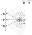
도 12는 본 발명의 일 실시예에 따른 SAR 재밍 시스템이 배치된 위치를 예시한 도면이다. 도 11에서 설명한 SAR 운용 플랫폼의 위치 및 이동 방향에 따른 허위 표적 생성 문제를 해결하기 위한 재머의 배치 방안에 대한 것으로, SAR 재밍 시스템은 보호 영역의 중심을 기준으로 상하좌우 4 개의 방향에 각각 배치되어 보호 영역의 전체를 커버할 수 있다. 보호 영역의 중심을 기준으로 4분면의 끝에 각각 재머를 배치한다. SAR 운용 플랫폼이 어떤 방향에서 보호 영역을 탐지를 시도하더라도 각 재머로부터 생성된 허위표적들이 보호 영역을 커버한다.12 is a diagram illustrating a location where a SAR jamming system according to an embodiment of the present invention is deployed. As for the method of arranging jammers to solve the problem of generating false targets according to the location and moving direction of the SAR operating platform described in FIG. 11, the SAR jamming system is arranged in four directions, It can cover the entire protection area. Jammers are placed at the ends of each quadrant based on the center of the protection area. No matter what direction the SAR operating platform tries to detect the protected area, false targets generated from each jammer cover the protected area.
SAR 재밍 시스템은 FIR 필터를 통해 지연 시간을 최소화하고 N 채널에 따른 허위 표적의 위치 및 거리(커버리지)를 제어할 수 있다.The SAR jamming system can minimize the delay time through the FIR filter and control the position and distance (coverage) of the false target according to N channels.
도 13은 본 발명의 다른 실시예에 따른 SAR 재밍 시스템의 허위 표적 생성 방법을 예시한 흐름도이다.13 is a flowchart illustrating a false target generation method of a SAR jamming system according to another embodiment of the present invention.
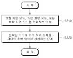
SAR(Synthetic Aperture Radar) 재밍 시스템에 의한 허위 표적 생성 방법은 고정 지연 모드, 가변 지연 모드, 또는 복합 지연 모드를 선택하는 단계(S310)를 수행하고, 고정 지연 모드, 가변 지연 모드, 또는 복합 지연 모드 중에서 선택된 하나의 모드에 따라 SAR의 위치의 반대 방향에 해당하는 후방 영역에 허위 표적을 생성하는 단계(S320)를 수행한다. SAR 재밍 시스템은 N(N은 자연수) 채널로 단위 지연 시간(△t)마다 신호를 지연시키는 FIR(Finite Impulse Response) 필터를 포함할 수 있다.A false target generation method using a synthetic aperture radar (SAR) jamming system includes selecting a fixed delay mode, a variable delay mode, or a complex delay mode (S310), and selecting the fixed delay mode, the variable delay mode, or the complex delay mode. A step of generating a false target in the rear area corresponding to the opposite direction of the position of the SAR according to one mode selected from the above (S320) is performed. The SAR jamming system may include a finite impulse response (FIR) filter that delays a signal per unit delay time (Δt) with N channels (N is a natural number).
고정 지연 모드는 SAR의 이동 시점에 맞춰 동일한 지연 시간이 설정된 모드이고, 가변 지연 모드는 SAR의 이동 시점에 맞춰 상이한 지연 시간이 설정된 모드이고, 복합 지연 모드는 SAR의 이동 시점에 맞춰 다수의 허위 표적 신호를 생성하는 모드일 수 있다.The fixed delay mode is a mode in which the same delay time is set according to the SAR movement time point, the variable delay mode is a mode in which different delay times are set according to the SAR movement time point, and the composite delay mode is a mode in which multiple false targets are set according to the SAR movement time point. It may be a mode for generating signals.
고정 지연 모드에서는 상기 허위 표적이 상기 SAR에 수직한 방향에 위치할 수 있다.In the fixed delay mode, the false target may be located in a direction perpendicular to the SAR.
가변 지연 모드에서는 허위 표적이 SAR에 대각 방향에 위치할 수 있다.In variable delay mode, false targets can be located diagonally to the SAR.
복합 지연 모드에서는 다수의 허위 표적 신호의 간격과 범위가 N 채널의 개수, 단위 지연 시간, 및 최대 지연 조건에 따라 결정될 수 있다. 최대 지연 조건은 하드웨어 또는 운용상 설정되는 조건이다.In the complex delay mode, intervals and ranges of multiple false target signals may be determined according to the number of N channels, unit delay time, and maximum delay conditions. The maximum delay condition is a condition set in hardware or operation.
SAR 재밍 시스템은 SAR의 이동 경로에 따른 느린 시간(slow-time)을 예측하여 느린 시간에 해당하는 N 개의 지연계수를 산출하여 저장하고 N 개의 지연계수를 FIR 필터에 적용할 수 있다.The SAR jamming system may predict a slow-time according to the SAR movement path, calculate and store N delay coefficients corresponding to the slow time, and apply the N delay coefficients to the FIR filter.
도 14는 본 발명의 또 다른 실시예에 따른 SAR 재밍 시스템의 배치 방법을 예시한 흐름도이다.14 is a flow chart illustrating a method of deploying a SAR jamming system according to another embodiment of the present invention.
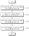
SAR(Synthetic Aperture Radar) 재밍 시스템의 배치 방법은 보호 영역의 중심을 기준으로 제1 방향에 제1 SAR 재머를 배치하는 단계(S410)를 수행하고, 보호 영역의 중심을 기준으로 제2 방향에 제2 SAR 재머를 배치하는 단계(S420)를 수행하고, 보호 영역의 중심을 기준으로 제3 방향에 제3 SAR 재머를 배치하는 단계(S430)를 수행하고, 및 보호 영역의 중심을 기준으로 제4 방향에 제4 SAR 재머를 배치하는 단계(S440)를 수행한다.A method of arranging a synthetic aperture radar (SAR) jamming system includes disposing a first SAR jammer in a first direction based on the center of a protection area (S410), and placing a first SAR jammer in a second direction based on the center of the protection area. The step of arranging 2 SAR jammers (S420) is performed, the step of arranging the third SAR jammer in the third direction based on the center of the protection area (S430) is performed, and the step of arranging the fourth SAR jammer based on the center of the protection area is performed. A step of arranging a fourth SAR jammer in the direction (S440) is performed.
제1 방향, 제2 방향, 제3 방향, 및 제4 방향은 상하좌우 4 개의 방향에 각각 대응할 수 있다.The first direction, the second direction, the third direction, and the fourth direction may respectively correspond to four directions of up, down, left, and right.
제1 SAR 재머, 제2 SAR 재머, 제3 SAR 재머, 및 제4 SAR 재머는 N(N은 자연수) 채널로 단위 지연 시간(△t)마다 신호를 지연시키는 FIR(Finite Impulse Response) 필터를 포함할 수 있다.The first SAR jammer, the second SAR jammer, the third SAR jammer, and the fourth SAR jammer include a finite impulse response (FIR) filter delaying a signal every unit delay time (Δt) with channels N (N is a natural number). can do.
제1 SAR 재머, 제2 SAR 재머, 제3 SAR 재머, 및 제4 SAR 재머는 SAR의 이동 경로에 따른 느린 시간(slow-time)을 예측하여 느린 시간에 해당하는 N 개의 지연계수를 산출하여 저장하고 N 개의 지연계수를 FIR 필터에 적용할 수 있다. FIR 필터는 신호를 수백 nsec 범위에서 지연시킨 후 출력할 수 있다.The 1st SAR jammer, the 2nd SAR jammer, the 3rd SAR jammer, and the 4th SAR jammer predict the slow-time along the SAR movement path, calculate and store N delay coefficients corresponding to the slow-time. and N delay coefficients can be applied to the FIR filter. The FIR filter can output signals after delaying them in the range of hundreds of nsec.
제1 SAR 재머에 의해 재밍되는 제1 영역, 제2 SAR 재머에 의해 재밍되는 제2 영역, 제3 SAR 재머에 의해 재밍되는 제3 영역, 및 제4 SAR 재머에 의해 재밍되는 제4 영역이 상호 오버랩되는 방식으로 보호 영역의 전체를 커버할 수 있다.A first area jammed by the first SAR jammer, a second area jammed by the second SAR jammer, a third area jammed by the third SAR jammer, and a fourth area jammed by the fourth SAR jammer are each other. It is possible to cover the entire protection area in an overlapping manner.
SAR 재밍 시스템에 포함된 구성요소들이 도 3 내지 도 6에서는 분리되어 도시되어 있으나, 복수의 구성요소들은 상호 결합되어 적어도 하나의 모듈로 구현될 수 있다. 구성요소들은 장치 내부의 소프트웨어적인 모듈 또는 하드웨어적인 모듈을 연결하는 통신 경로에 연결되어 상호 간에 유기적으로 동작한다. 이러한 구성요소들은 하나 이상의 통신 버스 또는 신호선을 이용하여 통신한다.Components included in the SAR jamming system are shown separately in FIGS. 3 to 6 , but a plurality of components may be combined with each other to be implemented as at least one module. The components are connected to a communication path connecting software modules or hardware modules inside the device and operate organically with each other. These components communicate using one or more communication buses or signal lines.
SAR 재밍 시스템은 하드웨어, 펌웨어, 소프트웨어 또는 이들의 조합에 의해 로직회로 내에서 구현될 수 있고, 범용 또는 특정 목적 컴퓨터를 이용하여 구현될 수도 있다. 장치는 고정배선형(Hardwired) 기기, 필드 프로그램 가능한 게이트 어레이(Field Programmable Gate Array, FPGA), 주문형 반도체(Application Specific Integrated Circuit, ASIC) 등을 이용하여 구현될 수 있다. 또한, 장치는 하나 이상의 프로세서 및 컨트롤러를 포함한 시스템온칩(System on Chip, SoC)으로 구현될 수 있다.The SAR jamming system may be implemented in a logic circuit by hardware, firmware, software, or a combination thereof, and may be implemented using a general-purpose or special-purpose computer. The device may be implemented using a hardwired device, a field programmable gate array (FPGA), an application specific integrated circuit (ASIC), or the like. Also, the device may be implemented as a System on Chip (SoC) including one or more processors and controllers.
SAR 재밍 시스템은 하드웨어적 요소가 마련된 컴퓨팅 디바이스에 소프트웨어, 하드웨어, 또는 이들의 조합하는 형태로 탑재될 수 있다. 컴퓨팅 디바이스는 각종 기기 또는 유무선 통신망과 통신을 수행하기 위한 통신 모뎀 등의 통신장치, 프로그램을 실행하기 위한 데이터를 저장하는 메모리, 프로그램을 실행하여 연산 및 명령하기 위한 마이크로프로세서 등을 전부 또는 일부 포함한 다양한 장치를 의미할 수 있다.The SAR jamming system may be installed in a computing device equipped with hardware elements in the form of software, hardware, or a combination thereof. A computing device includes a variety of devices including all or part of a communication device such as a communication modem for communicating with various devices or wired/wireless communication networks, a memory for storing data for executing a program, and a microprocessor for executing calculations and commands by executing a program. can mean a device.
본 실시예들은 본 실시예의 기술 사상을 설명하기 위한 것이고, 이러한 실시예에 의하여 본 실시예의 기술 사상의 범위가 한정되는 것은 아니다. 본 실시예의 보호 범위는 아래의 청구범위에 의하여 해석되어야 하며, 그와 동등한 범위 내에 있는 모든 기술 사상은 본 실시예의 권리범위에 포함되는 것으로 해석되어야 할 것이다.These embodiments are for explaining the technical idea of this embodiment, and the scope of the technical idea of this embodiment is not limited by these embodiments. The scope of protection of this embodiment should be construed according to the claims below, and all technical ideas within the scope equivalent thereto should be construed as being included in the scope of rights of this embodiment.
Claims (6)
Translated fromKorean보호 영역의 중심을 기준으로 제1 방향에 제1 SAR 재머를 배치하는 단계;
상기 보호 영역의 중심을 기준으로 제2 방향에 제2 SAR 재머를 배치하는 단계;
상기 보호 영역의 중심을 기준으로 제3 방향에 제3 SAR 재머를 배치하는 단계; 및
상기 보호 영역의 중심을 기준으로 제4 방향에 제4 SAR 재머를 배치하는 단계를 포함하며,
상기 제1 SAR 재머, 상기 제2 SAR 재머, 상기 제3 SAR 재머, 및 상기 제4 SAR 재머는 신호를 저장한 후 변조하여 변조된 DRFM 신호를 생성하는 상기 DRFM 및 N(상기 N은 자연수) 채널로 단위 지연 시간(△t)마다 상기 변조된 DRFM 신호를 지연시키는 FIR(Finite Impulse Response) 필터를 포함하고,
상기 SAR 재밍 시스템의 최소 지연 시간은 상기 DRFM에 의한 제1 최소 지연 시간과 상기 FIR 필터에 의한 제2 최소 지연 시간의 합에 해당하는 것을 특징으로 하는 SAR 재밍 시스템의 배치 방법.In the arrangement method of a synthetic aperture radar (SAR) jamming system in which a finite impulse response (FIR) filter is applied to a digital radio frequency memory (DRFM),
arranging a first SAR jammer in a first direction based on the center of the protection area;
disposing a second SAR jammer in a second direction based on the center of the protection area;
arranging a third SAR jammer in a third direction based on the center of the protection area; and
Disposing a fourth SAR jammer in a fourth direction based on the center of the protection area;
The 1st SAR jammer, the 2nd SAR jammer, the 3rd SAR jammer, and the 4th SAR jammer store signals and then modulate the DRFM to generate a modulated DRFM signal and N (where N is a natural number) channel A finite impulse response (FIR) filter delaying the modulated DRFM signal every unit delay time (Δt) by ,
The minimum delay time of the SAR jamming system corresponds to the sum of the first minimum delay time by the DRFM and the second minimum delay time by the FIR filter.
상기 제1 방향, 상기 제2 방향, 상기 제3 방향, 및 상기 제4 방향은 상하좌우 4 개의 방향에 각각 대응하는 것을 특징으로 하는 SAR 재밍 시스템의 배치 방법.According to claim 1,
Wherein the first direction, the second direction, the third direction, and the fourth direction correspond to four directions, respectively, up, down, left, and right.
상기 제1 SAR 재머, 상기 제2 SAR 재머, 상기 제3 SAR 재머, 및 상기 제4 SAR 재머는 SAR의 이동 경로에 따른 느린 시간(slow-time)을 예측하여 상기 느린 시간에 해당하는 상기 N 개의 지연계수를 산출하여 저장하고 상기 N 개의 지연계수를 상기 FIR 필터에 적용하는 것을 특징으로 하는 SAR 재밍 시스템의 배치 방법.According to claim 1,
The 1st SAR jammer, the 2nd SAR jammer, the 3rd SAR jammer, and the 4th SAR jammer predict a slow-time along the SAR movement path, and the N A method of deploying a SAR jamming system, characterized in that calculating and storing delay coefficients and applying the N delay coefficients to the FIR filter.
상기 FIR 필터는 상기 변조된 DRFM 신호를 수백 nsec 범위에서 지연시킨 후 출력하는 것을 특징으로 하는 SAR 재밍 시스템의 배치 방법.According to claim 1,
The method of deploying a SAR jamming system, characterized in that the FIR filter delays the modulated DRFM signal in a range of hundreds of nsec and outputs it.
상기 제1 SAR 재머에 의해 재밍되는 제1 영역, 상기 제2 SAR 재머에 의해 재밍되는 제2 영역, 상기 제3 SAR 재머에 의해 재밍되는 제3 영역, 및 상기 제4 SAR 재머에 의해 재밍되는 제4 영역이 상호 오버랩되는 방식으로 상기 보호 영역의 전체를 커버하는 것을 특징으로 하는 SAR 재밍 시스템의 배치 방법.According to claim 1,
A first area jammed by the first SAR jammer, a second area jammed by the second SAR jammer, a third area jammed by the third SAR jammer, and a second area jammed by the fourth SAR jammer. A method of deploying a SAR jamming system, characterized in that 4 areas cover the entirety of the protection area in a mutually overlapping manner.
Priority Applications (1)
| Application Number | Priority Date | Filing Date | Title |
|---|---|---|---|
| KR1020200111039AKR102469761B1 (en) | 2020-09-01 | 2020-09-01 | Method for disposing sar jamming system |
Applications Claiming Priority (1)
| Application Number | Priority Date | Filing Date | Title |
|---|---|---|---|
| KR1020200111039AKR102469761B1 (en) | 2020-09-01 | 2020-09-01 | Method for disposing sar jamming system |
Publications (2)
| Publication Number | Publication Date |
|---|---|
| KR20220029112A KR20220029112A (en) | 2022-03-08 |
| KR102469761B1true KR102469761B1 (en) | 2022-11-22 |
Family
ID=80813166
Family Applications (1)
| Application Number | Title | Priority Date | Filing Date |
|---|---|---|---|
| KR1020200111039AActiveKR102469761B1 (en) | 2020-09-01 | 2020-09-01 | Method for disposing sar jamming system |
Country Status (1)
| Country | Link |
|---|---|
| KR (1) | KR102469761B1 (en) |
Families Citing this family (2)
| Publication number | Priority date | Publication date | Assignee | Title |
|---|---|---|---|---|
| KR102750684B1 (en)* | 2022-03-29 | 2025-01-09 | 엘아이지넥스원 주식회사 | Multiple false target jamming signals generating method in response to synthetic aperture radar |
| KR102634432B1 (en)* | 2023-10-11 | 2024-02-06 | 국방과학연구소 | Method and system for generating jamming signal |
Citations (1)
| Publication number | Priority date | Publication date | Assignee | Title |
|---|---|---|---|---|
| KR101815387B1 (en)* | 2016-08-10 | 2018-01-04 | 국방과학연구소 | Jammer optimal position selection method with area analysis |
Family Cites Families (4)
| Publication number | Priority date | Publication date | Assignee | Title |
|---|---|---|---|---|
| DE102005063417B4 (en) | 2005-12-23 | 2021-01-07 | Airbus Defence and Space GmbH | Antenna for a high resolution synthetic aperture radar device |
| KR101427009B1 (en)* | 2012-12-17 | 2014-08-05 | 한국항공우주연구원 | Apparatus and method for generating jamming signal using synthetic aperture radar active transponder |
| KR20160050121A (en)* | 2014-10-28 | 2016-05-11 | 한남대학교 산학협력단 | High Resolution Target simulator with Dual Sampling Clock Rates. |
| KR102100851B1 (en) | 2018-07-30 | 2020-04-14 | 엘아이지넥스원 주식회사 | Jamming signal generating apparatus and method thereof |
- 2020
- 2020-09-01KRKR1020200111039Apatent/KR102469761B1/enactiveActive
Patent Citations (1)
| Publication number | Priority date | Publication date | Assignee | Title |
|---|---|---|---|---|
| KR101815387B1 (en)* | 2016-08-10 | 2018-01-04 | 국방과학연구소 | Jammer optimal position selection method with area analysis |
Also Published As
| Publication number | Publication date |
|---|---|
| KR20220029112A (en) | 2022-03-08 |
Similar Documents
| Publication | Publication Date | Title |
|---|---|---|
| KR102469760B1 (en) | Method for generating ghost target by sar jamming system | |
| US11906620B2 (en) | Software defined automotive radar systems | |
| Axelsson | Noise radar using random phase and frequency modulation | |
| US10976431B2 (en) | Adaptive filtering for FMCW interference mitigation in PMCW radar systems | |
| EP2834664B1 (en) | Radar with low interception probability | |
| de Wit et al. | Modified range-Doppler processing for FM-CW synthetic aperture radar | |
| CN111175750A (en) | Imaging method and device, device and storage medium for synthetic aperture radar | |
| KR102469761B1 (en) | Method for disposing sar jamming system | |
| Belcher et al. | Theory and simulation of ionospheric effects on synthetic aperture radar | |
| Younis | Digital beam-forming for high resolution wide swath real and synthetic aperture radar | |
| Neemat et al. | Reconfigurable range-Doppler processing and range resolution improvement for FMCW radar | |
| Bourdoux et al. | PMCW waveform cross-correlation characterization and interference mitigation | |
| US10302740B2 (en) | System and method for fast adaptive range doppler compression | |
| US10018717B2 (en) | Electromagnetic search and identification, in near field arenas | |
| KR102469759B1 (en) | Sar jamming system using digital n-channel fir filter | |
| JP2017516982A5 (en) | ||
| Scotti et al. | Field trial of a photonics‐based dual‐band fully coherent radar system in a maritime scenario | |
| Breit et al. | The TerraSAR-X multi-mode SAR processor—Algorithms and design | |
| Hasselmann | A simple algorithm for the direct extraction of the two-dimensional surface image spectrum from the return signal of a synthetic aperture radar | |
| Santi et al. | Passive multi-static SAR with GNSS transmitters: first theoretical and experimental results with point targets | |
| Gonzalez-Partida et al. | Stagger procedure to extend the frequency modulated interrupted continuous wave technique to high resolution radars | |
| Kurnia et al. | Passive Spacebourne SAR Using Opportunity of Illumination | |
| Davis | Design alternatives for foliage penetration SAR ultra wideband waveforms | |
| Tarasenko | Method of SAR sounding signals investigation and digital forming | |
| Dmitriev et al. | Mathematical and hardware modelling of MST radar signals |
Legal Events
| Date | Code | Title | Description |
|---|---|---|---|
| PA0109 | Patent application | Patent event code:PA01091R01D Comment text:Patent Application Patent event date:20200901 | |
| PA0201 | Request for examination | ||
| PE0902 | Notice of grounds for rejection | Comment text:Notification of reason for refusal Patent event date:20211228 Patent event code:PE09021S01D | |
| PG1501 | Laying open of application | ||
| E902 | Notification of reason for refusal | ||
| PE0902 | Notice of grounds for rejection | Comment text:Notification of reason for refusal Patent event date:20220610 Patent event code:PE09021S01D | |
| E701 | Decision to grant or registration of patent right | ||
| PE0701 | Decision of registration | Patent event code:PE07011S01D Comment text:Decision to Grant Registration Patent event date:20221110 | |
| GRNT | Written decision to grant | ||
| PR0701 | Registration of establishment | Comment text:Registration of Establishment Patent event date:20221117 Patent event code:PR07011E01D | |
| PR1002 | Payment of registration fee | Payment date:20221117 End annual number:3 Start annual number:1 | |
| PG1601 | Publication of registration |