KR102468344B1 - Management system for collection and disposal syringes to prevent reuse - Google Patents
Management system for collection and disposal syringes to prevent reuseDownload PDFInfo
- Publication number
- KR102468344B1 KR102468344B1KR1020200117630AKR20200117630AKR102468344B1KR 102468344 B1KR102468344 B1KR 102468344B1KR 1020200117630 AKR1020200117630 AKR 1020200117630AKR 20200117630 AKR20200117630 AKR 20200117630AKR 102468344 B1KR102468344 B1KR 102468344B1
- Authority
- KR
- South Korea
- Prior art keywords
- syringe
- collection box
- information
- collection
- space
- Prior art date
- Legal status (The legal status is an assumption and is not a legal conclusion. Google has not performed a legal analysis and makes no representation as to the accuracy of the status listed.)
- Active
Links
Images


Classifications
- A—HUMAN NECESSITIES
- A61—MEDICAL OR VETERINARY SCIENCE; HYGIENE
- A61M—DEVICES FOR INTRODUCING MEDIA INTO, OR ONTO, THE BODY; DEVICES FOR TRANSDUCING BODY MEDIA OR FOR TAKING MEDIA FROM THE BODY; DEVICES FOR PRODUCING OR ENDING SLEEP OR STUPOR
- A61M5/00—Devices for bringing media into the body in a subcutaneous, intra-vascular or intramuscular way; Accessories therefor, e.g. filling or cleaning devices, arm-rests
- A61M5/178—Syringes
- A61M5/31—Details
- A61M5/32—Needles; Details of needles pertaining to their connection with syringe or hub; Accessories for bringing the needle into, or holding the needle on, the body; Devices for protection of needles
- A61M5/3205—Apparatus for removing or disposing of used needles or syringes, e.g. containers; Means for protection against accidental injuries from used needles
- A—HUMAN NECESSITIES
- A61—MEDICAL OR VETERINARY SCIENCE; HYGIENE
- A61L—METHODS OR APPARATUS FOR STERILISING MATERIALS OR OBJECTS IN GENERAL; DISINFECTION, STERILISATION OR DEODORISATION OF AIR; CHEMICAL ASPECTS OF BANDAGES, DRESSINGS, ABSORBENT PADS OR SURGICAL ARTICLES; MATERIALS FOR BANDAGES, DRESSINGS, ABSORBENT PADS OR SURGICAL ARTICLES
- A61L11/00—Methods specially adapted for refuse
- A—HUMAN NECESSITIES
- A61—MEDICAL OR VETERINARY SCIENCE; HYGIENE
- A61M—DEVICES FOR INTRODUCING MEDIA INTO, OR ONTO, THE BODY; DEVICES FOR TRANSDUCING BODY MEDIA OR FOR TAKING MEDIA FROM THE BODY; DEVICES FOR PRODUCING OR ENDING SLEEP OR STUPOR
- A61M5/00—Devices for bringing media into the body in a subcutaneous, intra-vascular or intramuscular way; Accessories therefor, e.g. filling or cleaning devices, arm-rests
- A61M5/001—Apparatus specially adapted for cleaning or sterilising syringes or needles
- A—HUMAN NECESSITIES
- A61—MEDICAL OR VETERINARY SCIENCE; HYGIENE
- A61M—DEVICES FOR INTRODUCING MEDIA INTO, OR ONTO, THE BODY; DEVICES FOR TRANSDUCING BODY MEDIA OR FOR TAKING MEDIA FROM THE BODY; DEVICES FOR PRODUCING OR ENDING SLEEP OR STUPOR
- A61M5/00—Devices for bringing media into the body in a subcutaneous, intra-vascular or intramuscular way; Accessories therefor, e.g. filling or cleaning devices, arm-rests
- A61M5/50—Devices for bringing media into the body in a subcutaneous, intra-vascular or intramuscular way; Accessories therefor, e.g. filling or cleaning devices, arm-rests having means for preventing re-use, or for indicating if defective, used, tampered with or unsterile
- A61M5/5086—Devices for bringing media into the body in a subcutaneous, intra-vascular or intramuscular way; Accessories therefor, e.g. filling or cleaning devices, arm-rests having means for preventing re-use, or for indicating if defective, used, tampered with or unsterile for indicating if defective, used, tampered with or unsterile
- B—PERFORMING OPERATIONS; TRANSPORTING
- B65—CONVEYING; PACKING; STORING; HANDLING THIN OR FILAMENTARY MATERIAL
- B65F—GATHERING OR REMOVAL OF DOMESTIC OR LIKE REFUSE
- B65F1/00—Refuse receptacles; Accessories therefor
- B65F1/14—Other constructional features; Accessories
- G—PHYSICS
- G06—COMPUTING OR CALCULATING; COUNTING
- G06K—GRAPHICAL DATA READING; PRESENTATION OF DATA; RECORD CARRIERS; HANDLING RECORD CARRIERS
- G06K19/00—Record carriers for use with machines and with at least a part designed to carry digital markings
- G06K19/06—Record carriers for use with machines and with at least a part designed to carry digital markings characterised by the kind of the digital marking, e.g. shape, nature, code
- G—PHYSICS
- G06—COMPUTING OR CALCULATING; COUNTING
- G06Q—INFORMATION AND COMMUNICATION TECHNOLOGY [ICT] SPECIALLY ADAPTED FOR ADMINISTRATIVE, COMMERCIAL, FINANCIAL, MANAGERIAL OR SUPERVISORY PURPOSES; SYSTEMS OR METHODS SPECIALLY ADAPTED FOR ADMINISTRATIVE, COMMERCIAL, FINANCIAL, MANAGERIAL OR SUPERVISORY PURPOSES, NOT OTHERWISE PROVIDED FOR
- G06Q50/00—Information and communication technology [ICT] specially adapted for implementation of business processes of specific business sectors, e.g. utilities or tourism
- G06Q50/10—Services
- G06Q50/26—Government or public services
- A—HUMAN NECESSITIES
- A61—MEDICAL OR VETERINARY SCIENCE; HYGIENE
- A61M—DEVICES FOR INTRODUCING MEDIA INTO, OR ONTO, THE BODY; DEVICES FOR TRANSDUCING BODY MEDIA OR FOR TAKING MEDIA FROM THE BODY; DEVICES FOR PRODUCING OR ENDING SLEEP OR STUPOR
- A61M2205/00—General characteristics of the apparatus
- A61M2205/27—General characteristics of the apparatus preventing use
- A61M2205/273—General characteristics of the apparatus preventing use preventing reuse, e.g. of disposables
- A—HUMAN NECESSITIES
- A61—MEDICAL OR VETERINARY SCIENCE; HYGIENE
- A61M—DEVICES FOR INTRODUCING MEDIA INTO, OR ONTO, THE BODY; DEVICES FOR TRANSDUCING BODY MEDIA OR FOR TAKING MEDIA FROM THE BODY; DEVICES FOR PRODUCING OR ENDING SLEEP OR STUPOR
- A61M2205/00—General characteristics of the apparatus
- A61M2205/35—Communication
- A61M2205/3576—Communication with non implanted data transmission devices, e.g. using external transmitter or receiver
- A—HUMAN NECESSITIES
- A61—MEDICAL OR VETERINARY SCIENCE; HYGIENE
- A61M—DEVICES FOR INTRODUCING MEDIA INTO, OR ONTO, THE BODY; DEVICES FOR TRANSDUCING BODY MEDIA OR FOR TAKING MEDIA FROM THE BODY; DEVICES FOR PRODUCING OR ENDING SLEEP OR STUPOR
- A61M2205/00—General characteristics of the apparatus
- A61M2205/60—General characteristics of the apparatus with identification means
- A61M2205/6063—Optical identification systems
Landscapes
- Health & Medical Sciences (AREA)
- Engineering & Computer Science (AREA)
- General Health & Medical Sciences (AREA)
- Animal Behavior & Ethology (AREA)
- Business, Economics & Management (AREA)
- Veterinary Medicine (AREA)
- Public Health (AREA)
- Life Sciences & Earth Sciences (AREA)
- Anesthesiology (AREA)
- Hematology (AREA)
- Heart & Thoracic Surgery (AREA)
- Biomedical Technology (AREA)
- Vascular Medicine (AREA)
- Physics & Mathematics (AREA)
- Tourism & Hospitality (AREA)
- General Physics & Mathematics (AREA)
- Theoretical Computer Science (AREA)
- Human Resources & Organizations (AREA)
- Primary Health Care (AREA)
- Educational Administration (AREA)
- Epidemiology (AREA)
- Economics (AREA)
- Environmental & Geological Engineering (AREA)
- Marketing (AREA)
- Development Economics (AREA)
- Strategic Management (AREA)
- General Business, Economics & Management (AREA)
- Mechanical Engineering (AREA)
- Processing Of Solid Wastes (AREA)
- Refuse Collection And Transfer (AREA)
- Accommodation For Nursing Or Treatment Tables (AREA)
Abstract
Translated fromKoreanDescription
Translated fromKorean본 발명은 주사기 재사용 방지를 위해 병원 내에서는 사용 전 상태의 주사기와 사용 후 상태의 주사기 수량 및 내역을 구분하여 관리할 수 있으며, 사용이 완료된 주사기를 별도의 수거 장치 내에 모으고, 이와 같이 모아진 사용 완료 상태의 주사기들을 폐기 시설까지 이동시켜 최종 폐기 처리되는 과정에 이르기까지 주사기의 현재 위치 및 처리 상태를 실시간으로 모니터링하며 관리할 수 있는 주사기 수거 및 폐기 처리 관리시스템에 관한 것이다.In the present invention, in order to prevent reuse of syringes, the number and details of syringes before use and after use can be managed separately in the hospital, and used syringes are collected in a separate collection device, and the collected and used syringes are collected in this way The present invention relates to a syringe collection and disposal management system that can monitor and manage the current location and processing status of syringes in real time, from moving syringes in the same state to a disposal facility to the final disposal process.
의료용 주사기는 의료 환경 내에서 다양한 병원균이나 바이러스, 혈액 등에 직접적으로 노출되기 때문에 사용 후에는 쉽게 오염이 발생하며, 이를 재사용할 시 2차 감염의 문제가 발생하기 쉽기 때문에 일반적으로 의료용 주사기는 일회용으로 이용되고 있다.Since medical syringes are directly exposed to various pathogens, viruses, and blood in the medical environment, they are easily contaminated after use, and when reused, secondary infections are likely to occur. Generally, medical syringes are disposable. It is becoming.
다만, 이러한 일회용으로 사용되어야 할 의료용 주사기를 재사용 하는 경우가 지속 발생되고 있는데, 이로 인한 주사액 오염 및 집단 감염 확산의 문제가 지속적으로 발생되고 있으며, 이에 따라 주사기의 병원 내 입고 시점에서부터 사용 후 수거하여 최종적으로 폐기 시설로 옮겨져 폐기 처리가 완전히 완료되는 시점까지의 주사기의 상태 및 위치 이력을 종합적으로 관리하기 위한 기술이 지속적으로 요구되고 있다.However, cases of reuse of medical syringes that should be used for one-time use continue to occur, and the problem of contamination of the injection solution and spread of group infection continues to occur. A technology for comprehensively managing the status and location history of syringes until they are finally moved to a disposal facility and the disposal is completely completed is continuously required.
또한, 병원 내에서 사용이 완료된 주사기를 수거하는 과정에서부터 원천적으로 수거 후에는 주사기의 재사용 자체가 완전히 불가능하도록 하고, 이와 같이 수거되는 주사기의 상태를 수거 업체의 방문 전까지 안전하게 보관하기 위한 기술의 개발이 필요하다.In addition, from the process of collecting used syringes in the hospital, it is necessary to develop a technology to make it completely impossible to reuse the syringes after collection, and to safely store the collected syringes until the collection company visits. need.
이와 관련하여 주사기 재사용 방지를 위해 주사기의 사용 이력을 관리 또는 감독하기 위해 마련된 종래기술에 대한 선행문헌에는 일본 등록특허공보 JP 4977057호의 "의료 유체 및 그 용기에 관하는 정보를 관리하는 시스템 및 방법"(이하, '종래기술'이라고 함)이 있다.In this regard, in the prior art for managing or supervising the history of syringe use to prevent syringe reuse, Japanese Registered Patent Publication No. JP 4977057 entitled "System and method for managing medical fluid and information related to its container" (hereinafter referred to as 'prior art').
하지만, 종래기술을 비롯한 기존의 주사기 사용 이력을 관리 혹은 감독하는 시스템의 경우, 주사기를 구성하는 부속품의 일부만을 분리하여 재사용할 수 있는 가능성이 여전히 존재할 뿐만 아니라, 병원 내에서 사용 후 안전하게 주사기가 수거되더라도 병원 외 환경으로 수거된 주사기가 이동되는 과정에서 여전히 주사기 재사용을 시도할 수 있는 문제점이 있었다.However, in the case of a system that manages or supervises the history of existing syringes, including the prior art, there is still the possibility of separating and reusing only a part of the accessories constituting the syringe, and the syringe is safely collected after use in the hospital. Even if it is, there was a problem that the syringe reuse could still be attempted in the process of moving the syringe collected to the non-hospital environment.
아울러, 종래기술을 비롯한 기존의 주사기 사용 이력을 관리 혹은 감독하는 시스템의 경우, 사용이 완료된 주사기를 수거하는 용기 혹은 장치가 단순히 내부에 투입되는 사용 완료 상태의 주사기를 밀폐된 공간에 모으는 역할을 수행하는 기능만을 제공할 뿐, 내부에 수거된 주사기에 묻어있던 각종 병원균이나 바이러스, 혈액 등의 오염원이 계속 축적되거나 더욱 심각하게는 넓게 퍼지며 증폭되어 병원 내 환경의 위생문제를 악화시킬 수 있는 문제점이 있었다.In addition, in the case of a system that manages or supervises the history of existing syringes, including the prior art, a container or device that collects used syringes simply collects used syringes that are put inside into an enclosed space. There was a problem in that contaminants such as various pathogens, viruses, and blood, which were attached to the syringes collected inside, continued to accumulate or, more seriously, spread widely and amplified, which could worsen the hygiene problem of the hospital environment. .
본 발명은 상기 문제점을 해결하기 위해 창작된 것으로써, 본 발명의 목적은 주사기를 구성하는 부속품의 일부만을 분리하여 재사용할 수 있는 가능성을 완전히 배제시키고, 주사기 사용 후의 수거단계에서부터 수거업체에 의한 회수 및 이송단계, 최종적으로 폐기 시설 내에서의 폐기 처리단계에 이르기까지 모든 과정에서 주사기의 현재 처리 상태와 단계상의 위치에 관한 각종 정보를 언제든 실시간으로 모니터링하여 관리할 수 있는 기술을 제공하는데 있다.The present invention was created to solve the above problems, and an object of the present invention is to completely exclude the possibility of separating and reusing only a part of the accessories constituting the syringe, and to recover the syringe from the collection stage after use by the collection company. And to provide a technology that can monitor and manage various information about the current processing status of the syringe and the position on the stage in real time at any time in all processes from the transfer stage to the final disposal stage in the disposal facility.
아울러, 본 발명은 상기 문제점을 해결하기 위해 창작된 것으로써, 본 발명의 목적은 사용 후 수거되는 주사기 자체 및 주사기 내부에 잔류한 각종 오염원들을 효과적으로 제거하여 수거를 위해 모여지는 사용 완료 상태의 주사기의 누적으로 인한 오염원 증가, 외부로의 오염원 누출, 오염원으로 인한 각종 감염 문제들을 완전히 차단시킬 수 있는 기술을 제공하는데 있다.In addition, the present invention was created to solve the above problems, and an object of the present invention is to effectively remove the syringe itself collected after use and various contaminants remaining inside the syringe to collect the used syringe for collection. It is an object of the present invention to provide a technology capable of completely blocking an increase in pollution sources due to accumulation, leakage of pollution sources to the outside, and various infection problems caused by pollution sources.
상기 목적을 달성하기 위하여 본 발명에 따른 주사기 재사용 방지를 위한 주사기 수거 및 폐기 처리 관리시스템은, 전단에 주사 바늘이 결합되며, 내부에 길이방향을 따라 중공의 주사액 수용공간이 마련되는 실린더; 및 상기 실린더 후단 측으로부터 상기 주사액 수용공간에 수밀(水密)상태를 유지하면서 전후 이동될 수 있도록 삽입되는 플런저;를 포함하며, 상기 실린더의 측벽에 제1식별태그가 내장 설치되고, 상기 플런저 후단 누름판에 제2식별태그가 내장 설치되는 주사기의 재사용 방지를 위한 상기 주사기 수거 및 폐기 처리 관리시스템에 있어서, 병원 내 설치되어, 사용 전의 주사기 별 상기 제1식별태그 및 제2식별태그 각각에 기록된 식별코드를 읽어 두 개의 식별코드를 하나의 제1페어링 정보로 생성하는 제1리더기; 상기 제1리더기를 통해 생성된 주사기 별 제1페어링 정보가 수신되며, 수신된 제1페어링 정보를 기반으로 사용 전 상태의 주사기 내역이 기록된 제1주사기 관리 정보를 생성하여 내부 데이터베이스에 저장하는 관리서버; 및 상기 병원 내 설치되어, 상기 주사기 중 사용이 완료된 주사기가 투입되며, 사용 완료 후 투입되는 주사기 중 상기 제1식별태그 및 제2식별태그 각각에 기록된 식별코드 모두가 읽어지는 주사기에 한해 내부에 삽입 설치된 수거함으로 이동시키는 주사기 수거장치;를 포함한다.In order to achieve the above object, the syringe collection and disposal management system for preventing syringe reuse according to the present invention includes a cylinder having an injection needle coupled to the front end and a hollow injection solution receiving space along the longitudinal direction therein; and a plunger inserted from the rear end of the cylinder to be moved back and forth while maintaining a watertight state in the injection solution accommodating space, wherein a first identification tag is built-in and installed on a sidewall of the cylinder, and a pressing plate at the rear end of the plunger In the syringe collection and waste treatment management system for preventing reuse of syringes in which a second identification tag is built-in, identification recorded in each of the first identification tag and the second identification tag for each syringe before use, installed in a hospital a first reader for reading the code and generating two identification codes as one piece of first pairing information; First pairing information for each syringe generated through the first reader is received, and based on the received first pairing information, first syringe management information in which syringe details are recorded before use is generated and stored in an internal database. server; And installed in the hospital, used syringes among the syringes are injected, and among the syringes injected after completion of use, only the syringes in which all of the identification codes recorded in the first identification tag and the second identification tag are read are stored inside. A syringe collection device for moving the inserted collection box into the installed collection box.
여기서, 상기 주사기 수거장치는, 내부 공간이 상측의 주사기 식별 공간, 중간의 주사기 전처리 공간 및 하측의 수거함 배치 공간으로 구획되어 있으며, 상면 상에는 개방 시 상기 주사기 식별 공간과 외부를 연통시킬 수 있는 투입구가 마련되고, 상기 주사기 식별 공간을 형성하는 가변 프레임이 하강 이동하며 기울어질 시 상기 주사기 식별공간과 상기 주사기 전처리 공간이 연통될 수 있으며, 상기 주사기 전처리 공간과 상기 수거함 배치 공간을 상하로 구획하는 높이 상에 개방 시 상기 주사기 전처리 공간과 상기 수거함 배치 공간을 연통 시킬 수 있는 수거함 이동구가 마련되는 본체; 상기 주사기 식별 공간을 형성하는 프레임 상 상기 주사기 식별 공간에 투입 안착된 상기 주사기의 실린더와 마주하는 측벽 프레임 외측에 설치되어, 상기 제1식별태그에 기록된 제1식별코드를 읽는 제1식별모듈; 상기 주사기 식별 공간을 형성하는 프레임 상 상기 주사기 식별 공간에 투입 안착된 상기 주사기의 주사 바늘 및 플런저와 마주하는 양쪽 측벽 프레임 외측에 각각 설치되어, 상기 제2식별태그에 기록된 제2식별코드를 읽는 한 쌍의 제2식별모듈; 및 사용 완료 후 투입되는 상기 주사기가 개방된 상기 투입구를 통해 상기 주사기 식별 공간에 투입되어 상기 제1식별모듈을 통해 제1식별코드가 읽힘과 동시에 상기 제2식별모듈을 통해 제2식별코드 또한 읽힐 경우, 읽어진 제1식별코드 및 제2식별코드를 페어링하여 제2페어링 정보를 생성하여 상기 관리서버에 전송하고, 상기 주사기 식별 공간을 형성하는 가변 프레임을 하강 이동시켜 상기 주사기 전처리 공간으로 식별이 완료된 주사기가 이동될 수 있도록 하는 제어모듈;을 포함한다.Here, the syringe collection device has an internal space divided into an upper syringe identification space, a middle syringe pre-processing space, and a lower collection box arrangement space, and on the upper surface there is an inlet opening that allows the syringe identification space to communicate with the outside when opened. When the variable frame forming the syringe identification space moves downward and tilts, the syringe identification space and the syringe pre-processing space may communicate with each other, and the syringe pre-processing space and the collection box arrangement space are vertically partitioned at a height. a main body provided with a collection box moving tool capable of communicating the syringe pre-processing space and the collection box arrangement space when opened; A first identification module installed on the frame forming the syringe identification space and installed outside the sidewall frame facing the cylinder of the syringe put into and seated in the syringe identification space, and reading a first identification code recorded in the first identification tag; On the frame forming the syringe identification space, it is installed on the outside of both sidewall frames facing the injection needle and plunger of the syringe inserted and seated in the syringe identification space, and reads the second identification code recorded in the second identification tag. a pair of second identification modules; and the syringe injected after completion of use is inserted into the syringe identification space through the open inlet, the first identification code is read through the first identification module, and the second identification code is also read through the second identification module. In this case, the read first identification code and the second identification code are paired to generate second pairing information and transmitted to the management server, and the variable frame forming the syringe identification space is moved downward to identify the syringe pre-processing space. It includes; a control module that allows the completed syringe to be moved.
또한, 상기 본체는, 작동상태에 따라 상기 투입구의 개폐를 조절할 수 있는 투입구 개폐부; 상기 주사기 식별 공간을 형성하는 프레임 상 바닥면을 포함하는 상기 가변 프레임 일측에 연결되어 작동상태에 따라 상기 가변 프레임을 상하로 기울여 상기 주사기 식별공간에 투입된 상기 주사기의 상기 주사기 전처리 공간으로의 이동 여부를 조절할 수 있는 프레임 가변부; 및 상기 주사기 전처리 공간상에 경사면을 형성하는 프레임 구조로서, 경사면의 하단부가 상기 수거함 이동구를 향하고, 경사면의 상단부가 상기 프레임 가변부의 작동에 의해 상기 가변 프레임이 최하단의 위치로 기울어졌을 경우의 상기 가변 프레임 최하단부와 접해 경사면의 상호 연결이 이루어질 수 있는 이동 경사부;를 포함하며, 상기 제어모듈은, 상기 제1식별모듈 및 제2식별모듈을 통해 읽어진 제1식별코드와 제2식별코드를 페이링하여 제2페어링 정보를 생성하는 페어링 정보 생성부; 상기 관리서버와 무선 통신 네트워크를 구축하고, 상기 페어링 정보 생성부를 통해 생성된 제2페어링 정보를 상기 관리서버에 전송하는 통신부; 및 상기 투입구 개폐부 및 프레임 가변부의 작동상태를 제어하는 동작 제어부;를 포함하며, 상기 관리서버는 상기 통신부로부터 수신되는 제2페어링 정보를 기반으로 상기 제1주사기 관리 정보를 갱신하고, 사용이 완료된 상태의 주사기 내역이 기록된 제2주사기 관리 정보를 생성하여 내부 데이터베이스에 저장한다.In addition, the main body, the inlet opening and closing portion capable of adjusting the opening and closing of the inlet according to the operating state; It is connected to one side of the variable frame including a bottom surface on the frame forming the syringe identification space and tilts the variable frame up and down according to an operating state to determine whether the syringe injected into the syringe identification space moves to the syringe pre-processing space. Adjustable frame variable part; and a frame structure forming an inclined surface on the syringe pre-processing space, wherein a lower end of the inclined surface faces the collection box moving tool and an upper end of the inclined surface is tilted to the lowermost position by the operation of the variable frame unit. and a movable inclination portion that is in contact with the lowermost end of the variable frame and interconnected with the inclined surface, wherein the control module receives the first identification code and the second identification code read through the first identification module and the second identification module. a pairing information generator configured to generate second pairing information by pairing; a communication unit for establishing a wireless communication network with the management server and transmitting second pairing information generated through the pairing information generation unit to the management server; and an operation control unit for controlling operating states of the inlet opening/closing unit and the frame variable unit, wherein the management server updates the first syringe management information based on the second pairing information received from the communication unit, and the use is complete. The second syringe management information in which the history of the syringe is recorded is generated and stored in an internal database.
여기서, 상기 가변 프레임은 상기 프레임 가변부의 작동에 의해 상기 가변 프레임이 최상단의 위치로 기울어져 상기 주사기 식별 공간을 닫힌 공간으로 형성할 시 상기 주사기 식별 공간을 형성하는 프레임 상의 바닥면에 해당하게 되는 상기 가변 프레임의 일부 면이 하방으로 기울어진 구조로 마련된다.Here, the variable frame corresponds to the bottom surface of the frame forming the syringe identification space when the variable frame is tilted to the uppermost position by the operation of the frame variable unit to form the syringe identification space as a closed space. A part of the variable frame is provided in a structure inclined downward.
그리고 상기 주사기 수거장치는, 상기 주사기 식별공간으로부터 상기 주사기 전처리 공간으로 떨어진 상기 주사기가 경사 이동하게 되는 상기 이동 경사부의 상부 경사면을 마주보는 상기 본체 내부 상기 주사기 전처리 공간상의 일측에 설치되어, 상기 이동 경사부의 상부 경사면 측으로 UV광을 조사하는 UV 살균모듈;을 더 포함한다.And the syringe collection device is installed on one side of the syringe pre-processing space inside the main body facing the upper inclined surface of the movable inclined part on which the syringe, which has fallen from the syringe identification space to the syringe pre-processing space, tilts, and moves, A UV sterilization module for irradiating UV light toward the upper inclined surface of the unit; further includes.
아울러, 상기 본체는, 작동상태에 따라 상기 수거함 배치 공간에 해당하는 수거함 설치홈의 개폐를 조절할 수 있는 설치홈 개폐부;를 더 포함하며, 상기 주사기 수거장치는, 내부에 주사기 수거 공간이 마련되고, 상기 설치홈 개폐부가 개방된 상태에서 상기 수거함 설치홈에 삽입 설치 가능하며, 상기 수거함 설치홈에 삽입 설치되어 상기 수거함 배치 공간에 배치될 시 상부면의 상기 수거함 이동구 아래 대응되는 위치에 상하로 개방된 수거함 개방구가 구비되는 주사기 수거함;을 더 포함하며, 상기 주사기 수거함은, 작동상태에 따라 상기 수거함 개방구의 개폐를 조절하여 상기 수거함 이동구와 상기 수거함 개방구를 통한 상기 주사기 전처리 공간과 상기 주사기 수거 공간 간의 연통 여부가 조절될 수 있도록 하는 개방구 개폐부; 상기 주사기 수거함 내부 상측 상기 수거함 개방구 주변부에 상기 수거함 개방구로 유입되는 주사기를 감지하여, 수거된 주사기의 개수에 대한수거 수량 정보를 생성하는 수거 감지부; 상기 주사기 수거함 하부 바닥면 측에 약액 흡수패드의 설치가 이루어질 수 있도록 소정의 설치공간을 형성하고, 상부면에 다수의 약액 이동구가 구비되어 상기 주사기 수거 공간에 모여진 사용 완료 상태의 상기 주사기로부터 유출되는 약액이 상기 약액 흡수패드로 이동될 수 있도록 하는 패드 설치부; 상기 개방구 개폐부의 작동상태를 제어하는 수거함 제어부; 상기 제어모듈의 통신부와 무선 통신 네트워크를 구축하여, 상기 통신부를 통해 제2페어링 정보를 수신하는 수거함 통신부; 및 상기 수거함 통신부를 통해 수신되는 제2페어링 정보 및 상기 수거 감지부를 통해 생성되는 수거 수량 정보를 기록 저장하는 정보 저장부;를 포함하며, 상기 동작 제어부는 프레임 가변부의 작동상태 제어를 통해 상기 가변 프레임의 위상을 아래로 회전시켜 상기 주사기 식별공간에 투입된 상기 주사기가 상기 주사기 전처리 공간으로 이동되도록 한 뒤, 다시 상기 가변 프레임의 위상을 위로 회전시켜 최초 상태로 회복시키는 일련의 과정이 완료되고 나면 수거함 제어명령 신호를 생성하여 상기 통신부를 통해 상기 수거함 통신부에 전송되도록 하며, 상기 수거함 통신부로 상기 수거함 제어명령 신호가 수신되면, 상기 수거함 제어부는 상기 개방구 개폐부의 작동상태 제어를 통해 상기 수거함 개방구를 개방시켜 상기 주사기 전처리 공간을 거친 상기 주사기가 상기 수거함 이동구와 상기 수거함 개방구를 통과하여 상기 주사기 수거 공간에 수거될 수 있도록 한다.In addition, the main body further includes an installation groove opening and closing portion capable of adjusting the opening and closing of the collection box installation groove corresponding to the collection box arrangement space according to an operating state, and the syringe collection device has a syringe collection space inside, It can be inserted and installed into the collection box installation groove in an open state of the installation groove opening/closing part, and when inserted into the collection box installation groove and placed in the collection box arrangement space, it is vertically opened at the corresponding position below the collection box moving tool on the upper surface. The syringe collection box further includes a syringe collection box provided with a collection box opening, wherein the syringe collection box controls the opening and closing of the collection box opening according to an operating state to collect the syringe pre-processing space and the syringe through the collection box moving part and the collection box opening. An opening opening/closing unit that allows communication between spaces to be controlled; a collection detection unit configured to detect syringes flowing into the collection box opening at an upper portion of the syringe collection box and generate collection quantity information on the number of collected syringes; A predetermined installation space is formed on the lower bottom surface of the syringe collection box so that a drug absorption pad can be installed, and a plurality of drug solution moving devices are provided on the upper surface to flow out of the used syringes gathered in the syringe collection space. a pad installation unit allowing the chemical solution to be moved to the drug absorption pad; a collection box control unit controlling an operating state of the opening/closing unit of the opening; a collection box communication unit configured to establish a wireless communication network with the communication unit of the control module and receive second pairing information through the communication unit; and an information storage unit for recording and storing second pairing information received through the collection box communication unit and collection quantity information generated through the collection detection unit, wherein the operation controller controls the operating state of the frame variable unit to control the variable frame. After a series of processes of rotating the phase of the variable frame downward to move the syringe injected into the syringe identification space to the syringe pre-processing space and then rotating the phase of the variable frame upward to restore the initial state are completed, the collection box is controlled. A command signal is generated and transmitted to the collection box communication unit through the communication unit, and when the collection box control command signal is received by the collection box communication unit, the collection box control unit opens the collection box opening by controlling the operating state of the opening/closing unit. so that the syringe passing through the syringe pre-processing space can be collected in the syringe collection space by passing through the collection box moving part and the collection box opening.
여기서, 상기 주사기 수거함은, 상기 주사기 수거함 내부 상측 상기 수거함 개방구 아래에 하방으로 기울어진 경사면을 형성하여 상기 수거함 개방구로 유입되는 상기 주사기가 부딪쳐 매번 상기 주사기 수거 공간 내 다양한 임의 위치에 모일 수 있도록 하는 수거함 경사부;를 더 포함한다.Here, the syringe collection box forms an inclined surface below the collection box opening on the inside of the syringe collection box, so that the syringes flowing into the collection box opening collide and gather at various arbitrary positions in the syringe collection space each time It further includes; a collection box inclined portion.
아울러, 상기 동작 제어부는 상기 설치홈 개폐부의 작동상태를 제어하고, 상기 주사기 재사용 방지를 위한 주사기 수거 및 폐기 처리 관리시스템은, 상기 동작 제어부의 제어를 통해 상기 설치홈 개폐부가 개방된 상기 주사기 수거장치의 상기 수거함 설치홈으로부터 상기 주사기 수거함을 꺼내 상기 주사기 수거함을 주사기 폐기시설로 이동시키는 운반차량에 설치되는 제2리더기;를 더 포함하며, 상기 제2리더기는, 정보의 저장 공간을 제공하는 제1메모리부; 상기 주사기 수거함의 상기 정보 저장부에 저장된 제2페어링 정보를 읽어 상기 제1메모리부에 저장하는 제1정보 리딩부; 상기 운반차량의 위치정보를 생성하는 GPS부; 및 상기 관리서버와 무선 통신 네트워크를 구축하고, 상기 제1메모리부에 저장된 제2페어링 정보와 상기 GPS부를 통해 생성되는 상기 운반차량의 위치정보를 기 설정된 주기마다 페어링한 제3페어링정보를 생성하여 상기 관리서버에 전송하는 수거함 위치 알림부;를 포함하며, 상기 관리서버는 상기 수거함 위치 알림부로부터 수신되는 제3페어링 정보를 기반으로 상기 제2주사기 관리 정보를 갱신하고, 상기 운반차량을 통해 주사기 폐기시설로 이동 중인 상태의 주사기 내역이 시간에 따라 상기 운반차량의 위치정보와 함께 기록된 제3주사기 관리 정보를 생성하여 내부 데이터베이스에 저장한다.In addition, the operation control unit controls the operating state of the opening and closing part of the installation groove, and the syringe collection and disposal management system for preventing reuse of the syringe is the syringe collection device in which the opening and closing part of the installation groove is opened through the control of the operation control unit. A second reader installed on a transportation vehicle for taking out the syringe collection box from the collection box installation groove of the syringe collection box and moving the syringe collection box to a syringe disposal facility, wherein the second reader is a first reader providing a storage space for information memory unit; a first information reading unit reading second pairing information stored in the information storage unit of the syringe collection box and storing it in the first memory unit; a GPS unit generating location information of the transportation vehicle; and establishing a wireless communication network with the management server, and generating third pairing information by pairing the second pairing information stored in the first memory unit with the location information of the transport vehicle generated through the GPS unit at predetermined intervals. and a collection box location notification unit that transmits the information to the management server, wherein the management server updates the second syringe management information based on third pairing information received from the collection box location notification unit and uses the syringe through the delivery vehicle. The third syringe management information, in which the history of the syringe in the state of being moved to the disposal facility is recorded together with the location information of the transport vehicle according to time, is generated and stored in the internal database.
아울러, 상기 주사기 재사용 방지를 위한 주사기 수거 및 폐기 처리 관리시스템은, 상기 주사기 폐기시설 내에 설치되며, 상기 운반차량을 통해 상기 주사기 폐기시설로 이동되어 온 상기 주사기 수거함에 폐기 권한정보를 전송하는 제3리더기;를 더 포함하며, 상기 제3리더기는, 정보의 저장 공간을 제공하며, 폐기 권한정보가 저장된 제2메모리부; 상기 주사기 수거함의 상기 정보 저장부에 저장된 제2페어링 정보를 읽어 상기 제2메모리부에 저장하는 제2정보 리딩부; 상기 주사기 수거함의 상기 수거함 통신부와 무선 통신 네트워크를 구축하고, 상기 제2메모리부에 저장된 폐기 권한정보를 상기 주사기 수거함에 전송하는 권한정보 전송부; 상기 관리서버와 무선 통신 네트워크를 구축하고, 상기 제2메모리부에 저장된 제2페어링 정보와 상기 권한정보 전송부를 통해 상기 주사기 수거함에 상기 제2메모리부에 저장된 폐기 권한정보를 전송할 시 생성되는 폐기 알림정보를 페어링한 제4페어링정보를 생성하여 상기 관리서버에 전송하는 폐기 알림부;를 포함하며, 상기 주사기 수거함의 상기 정보 저장부 내에는 정당한 폐기 권한정보의 인증을 위한 인증 기준정보가 기 설정 저장된다.In addition, the syringe collection and disposal management system for preventing reuse of the syringe is installed in the syringe disposal facility and transmits disposal authorization information to the syringe collection box that has been moved to the syringe disposal facility through the transport vehicle. The third reader includes: a second memory unit which provides a storage space for information and stores discard authority information; a second information reading unit reading second pairing information stored in the information storage unit of the syringe collection box and storing the second pairing information in the second memory unit; an authorization information transmitter for establishing a wireless communication network with the syringe collection box communication unit of the syringe collection box and transmitting discard authorization information stored in the second memory unit to the syringe collection box; Disposal notification generated when a wireless communication network is established with the management server and the second pairing information stored in the second memory unit and the discard authority information stored in the second memory unit are transmitted to the syringe collection box through the authority information transmission unit and a discard notification unit generating fourth pairing information paired with information and transmitting the same to the management server. do.
여기서, 상기 주사기 수거함은, 상기 주사기 수거함 일측에 상기 주사기 수거함 내부에 수거되어 모인 상기 주사기를 꺼낼 수 있도록 개폐 가능한 문 형태로 구비된 개폐부분 및 작동상태에 따라 상기 개폐부분의 개폐 가능 여부를 조절하기 위해 상기 개폐부분 일측에 설치되는 잠금부분을 포함하는 수거함 개폐부; 및 상기 제3리더기의 상기 권한정보 전송부로부터 상기 수거함 통신부를 통해 수신되는 폐기 권한정보를 상기 정보 저장부 내에 저장된 인증 기준정보와 비교하는 폐기 권한 인증을 통해, 일치하는 인증 기준정보가 존재할 시 상기 잠금부분의 작동상태를 해제상태로 제어하여 상기 개폐부분이 개폐 가능한 상태가 되도록 하는 폐기 권한 인증부;를 포함하며, 상기 관리서버는 상기 폐기 알림부로부터 수신되는 제4페어링정보를 기반으로 상기 제3주사기 관리 정보를 갱신하고, 상기 주사기 폐기시설로 이동되어 폐기 처리되는 상태의 주사기 내역이 기록된 제4주사기 관리 정보를 생성하여 내부 데이터베이스에 저장한다.Here, the syringe collection box is an opening and closing part provided in the form of an openable door to take out the syringes collected and collected inside the syringe collection box at one side of the syringe collection box, and adjusting whether the opening and closing part can be opened or closed according to an operating state. a collection box opening and closing part including a locking part installed on one side of the opening and closing part to do so; and discard authority authentication that compares the discard authority information received from the authority information transmission unit of the third reader through the collection box communication unit with the authentication standard information stored in the information storage unit, when matching authentication standard information exists. and a discard authority authentication unit that controls the operating state of the locking part to a release state so that the opening/closing part can be opened and closed. 3. Syringe management information is updated, and fourth syringe management information, in which details of syringes being moved to the syringe disposal facility and disposed of, are recorded, is generated and stored in an internal database.
본 발명에 의하면 다음과 같은 효과가 있다.According to the present invention, there are the following effects.
첫째, 주사기를 사용 후 주사기 수거장치에 투입하여 수거함에 모으기 위해서는 주사기의 실린더와 플런저 각각에 설치된 개별 식별태그를 모두가 읽어지는 경우가 전제되도록 하여 주사기의 일부 구성품만을 분리하여 재사용할 경우 바로 확인이 가능하도록 함으로써, 주사기 자체의 재사용뿐만 아니라 일부 구성품의 재사용까지도 사전에 차단할 수 있다.First, in order to put the syringe into the syringe collection device after use and collect it in the collection box, it is premised that all of the individual identification tags installed on the cylinder and plunger of the syringe are read, so that only some components of the syringe are separated and reused. By making it possible, not only the reuse of the syringe itself but also the reuse of some components can be blocked in advance.
둘째, 주사기의 병원 내 입고 시점, 주사기의 사용 후 수거장치로의 투입 시점, 수거장치 내 수거함을 수거업체가 회수하여 운송차량을 통해 폐기시설로 이동시키는 시점, 폐기시설 내에 도착한 수거함을 열어 내부에 수거된 사용완료 상태의 주사기를 폐기 처리하는 시점 각각에 위치한 주사기들의 상태 내역 및 현황을 관리자가 언제나 실시간을 확인하여 모니터링 함으로써, 종합적인 주사기의 처리 상태 및 재사용 방지를 효율적으로 관리 감독할 수 있다.Second, when the syringe is received in the hospital, when the syringe is put into the collection device after use, when the collection company collects the collection box in the collection device and moves it to the disposal facility through a transport vehicle, and opens the collection box arrived in the disposal facility The manager can always check and monitor the status details and current status of the syringes located at each point of disposal of the collected syringes in the used state in real time, so that the comprehensive syringe processing status and reuse prevention can be efficiently managed and supervised.
셋째, 사용 후 주사기 수거장치 내에 투입되는 주사기를 UV 살균을 통해 살균 처리할 뿐만 아니라 장치 내부 공간의 공기 역시 살균이 이루어지도록 하여 오염원의 잔존을 최대한 없애고, 최종적으로 수거함에 떨어져 주사기가 모여진 상태에서 주사기 내 잔류하고 있던 약액 성분들이 누출되더라도 아래 배치된 약액 흡수패드에 흡수되어 수거함 내부가 오염되지 않도록 할 수 있다.Third, the syringes put into the syringe collection device after use are sterilized through UV sterilization, and the air inside the device is also sterilized to eliminate the remaining contaminants as much as possible. Even if the remaining chemical components leak, they are absorbed by the chemical absorption pad disposed below, so that the inside of the collection box is not contaminated.
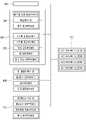
도1은 본 발명에 따른 주사기 재사용 방지를 위한 주사기 수거 및 폐기 처리 관리시스템을 도시한 구성도이다.
도2는 본 발명에 따른 주사기 재사용 방지를 위한 주사기 수거 및 폐기 처리 관리시스템의 세부 구성을 도시한 블록도이다.
도3은 본 발명에 따른 주사기 수거 및 폐기 처리 관리시스템 내 주사기 수거장치의 구조를 도시한 사시도이다.
도4는 본 발명에 따른 주사기 수거 및 폐기 처리 관리시스템 내 주사기 수거장치의 주사기 수거함 분리 형태를 도시한 분해 사시도 이다.
도5는 발명에 따른 주사기 수거 및 폐기 처리 관리시스템 내 주사기 수거장치의 주사기 식별 과정에서의 내부 구조를 도시한 단면도이다.
도6은 발명에 따른 주사기 수거 및 폐기 처리 관리시스템 내 주사기 수거장치의 주사기 전처리 및 수거 과정에서의 내부 구조를 도시한 단면도이다.1 is a block diagram showing a syringe collection and disposal management system for preventing reuse of a syringe according to the present invention.
Figure 2 is a block diagram showing the detailed configuration of the syringe collection and waste treatment management system for preventing reuse of the syringe according to the present invention.
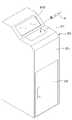
Figure 3 is a perspective view showing the structure of the syringe collection device in the syringe collection and waste treatment management system according to the present invention.
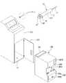
Figure 4 is an exploded perspective view showing a separate form of the syringe collection box of the syringe collection device in the syringe collection and waste treatment management system according to the present invention.
5 is a cross-sectional view showing the internal structure in the syringe identification process of the syringe collection device in the syringe collection and waste management system according to the present invention.
6 is a cross-sectional view showing the internal structure of the syringe collection device in the syringe collection and waste treatment management system according to the present invention in the process of pre-processing and collecting syringes.
본 발명의 바람직한 실시예에 대하여 첨부된 도면을 참조하여 더 구체적으로 설명하되, 이미 주지된 기술적 부분에 대해서는 설명의 간결함을 위해 생략하거나 압축하기로 한다.A preferred embodiment of the present invention will be described in more detail with reference to the accompanying drawings, but already well-known technical parts will be omitted or compressed for conciseness of description.
<주사기 재사용 방지를 위한 주사기 수거 및 폐기 처리 관리시스템의 구성요소에 관한 설명><Description of the components of the syringe collection and disposal management system to prevent reuse of syringes>
먼저, 본 발명의 주사기 재사용 방지를 위한 주사기 수거 및 폐기 처리 관리시스템(1000)에 대해 이하에서 도1 내지 도2의 구성도 및 블록도를 참조하여 상세하게 설명한다.First, the syringe collection and waste
이를 위해, 본 발명의 주사기 재사용 방지를 위한 주사기 수거 및 폐기 처리 관리시스템(1000)은 도1에 도시된 바와 같이 제1리더기(100); 관리서버(200); 주사기 수거장치(300); 제2리더기(400) 제3리더기(500) 및 관리단말(600);을 포함한다.To this end, the syringe collection and
또한, 본 발명의 주사기 재사용 방지를 위한 주사기 수거 및 폐기 처리 관리시스템(1000)을 통해 관리 기능의 적용 대상이 되는 주사기(10)는 해당 시스템 내 각종 구성간의 연계를 위해 특정 구성의 부가 및 구조적 변형을 거친 주사기(10)가 적용된다.In addition, the
구체적으로, 본 발명의 주사기 재사용 방지를 위한 주사기 수거 및 폐기 처리 관리시스템(1000)에 이용되는 주사기(10)는 주사 바늘(11), 실린더(12), 플런저(13)를 비롯해, 제1식별태그(12T) 및 제2식별태그(13T) 또한 포함한다.Specifically, the
여기서, 실린더(12)는 전단에 주사 바늘(11)이 결합되며, 내부에 길이방향을 따라 중공의 주사액 수용공간이 마련되는 구성으로서, 이러한 실린더(12)의 측벽에 제1식별태그(12T)가 내장 설치된다.Here, the
이러한 제1식별태그(12T) 및 제2식별태그(13T)는 각각의 실린더(12) 및 플런저(13)를 구분할 수 있는 고유의 식별코드를 담고 있는 기록 수단으로, RFID 리더기를 통해 내부에 기록 저장된 식별코드를 읽을 수 있도록 마련되는 RFID 태그의 형태에서부터 통신 네트워크를 구축하거나 태그로 접속 가능한 러더기를 통해 내부 데이터베이스와 같은 별도의 저장 공간에 기록 저장된 식별코드를 읽거나 제공받아 확인할 수 있도록 마련되는 정보 저장모듈 등 다양한 실시 형태로 구현될 수 있다.The
또한, 플런저(13)는 실린더(12) 후단 측으로부터 주사액 수용공간에 수밀(水密)상태를 유지하면서 전후 이동될 수 있도록 삽입되며, 플런저(13) 후단 누름판(13B)에 제2식별태그(13T)가 내장 설치된다.In addition, the
제1리더기(100)는 병원(H) 내 설치되어, 사용 전의 주사기(10) 별 제1식별태그(12T) 및 제2식별태그(13T) 각각에 기록된 식별코드를 읽어 두 개의 식별코드를 하나의 제1페어링 정보로 생성하고, 생성된 제1페어링 정보를 아래 설명될 관리서버(200)에 전송한다.The
이에 따라, 제1페어링 정보는 현재 병원(H) 내로 입고된 주사기(10)에 대한 정보를 해당 주사기(10) 각각을 구성하는 실린더(12) 및 플런저(13)에 대한 고유식별정보끼리 짝을 이루는 형태를 갖추게 된다.Accordingly, the first pairing information pairs information about the
따라서 제1페어링 정보를 통해서 관리자는 현재 병원(H) 내에 입고되어 사용 전인 상태의 주사기(10)가 몇 개이고 어떤게 있는지에 대한 내역을 확인할 수 있고, 그 중 실린더(12) 및 플런저(13) 각각이 분리되지 않고 하나의 페어를 이루고 있는지를 모니터링할 수 있다.Therefore, through the first pairing information, the administrator can check the details of how many and which
이와 관련하여, 관리서버(200)는 제1리더기(100)를 통해 생성된 주사기 별 제1페어링 정보가 수신되며, 수신된 제1페어링 정보를 기반으로 사용 전 상태의 주사기 내역이 기록된 제1주사기 관리 정보를 생성하여 내부 데이터베이스에 저장한다.In this regard, the
구체적으로, 관리서버(200)는 제1데이터베이스(410)에 제1리더기(100)를 통해 생성 후 수신되는 제1페어링 정보를 저장하며, 이와 같이 저장된 제1페어링 정보를 관리서버(200)에 접속한 관리단말(600)이 확인 요청할 경우 사용 전 상태의 주사기 내역을 관리자가 확인할 수 있게 된다.Specifically, the
이와 같이 병원(H) 내 입고된 후 제1리더기(100)를 통한 1차 내역 검증이 완료된 주사기(10)들은 각 부서에 배치되어 사용되게 되는데, 일회성을 사용이 완료되고 나면 의사는 사용 완료 상태의 주사기(10)를 주사기 수거장치(300)에 투입하여 주사기가 한꺼번에 회수되어 폐기처리 시설로 이동될 수 있도록 주사기 수거함(360)에 모이도록 함과 동시에 근본적인 주사기 재사용을 차단시킨다.In this way, after being stocked in the hospital (H), the syringes (10) for which the primary history verification has been completed through the first reader (100) are placed and used in each department. After the one-time use is completed, the doctor is used The
주사기 수거장치(300)는 병원(H) 내 설치되어, 주사기(10) 중 사용이 완료된 주사기(10)가 투입되며, 사용 완료 후 투입되는 주사기(10) 중 제1식별태그(12T) 및 제2식별태그(13T) 각각에 기록된 식별코드 모두가 읽어지는 주사기에 한해 내부에 삽입 설치된 수거함(360)으로 이동시킨다.The
이를 위해, 주사기 수거장치(300)는 도3 내지 도6에 도시된 바와 같이 본체(310), 제1식별모듈(320), 제2식별모듈(330), 제어모듈(340), UV 살균모듈(350) 및 주사기 수거함(360)을 포함한다.To this end, the
우선, 본체(310)는 주사기 수거장치(300)의 전체 하우징에 해당하는 부분으로, 내부 공간이 상측의 주사기 식별 공간(T1), 중간의 주사기 전처리 공간(T2) 및 하측의 수거함 배치 공간(T3)으로 구획되어 있다.First of all, the
또한, 도3 및 도5에 도시된 바와 같이 본체(310)의 상면 상에는 개방 시 주사기 식별 공간(T1)과 외부를 연통시킬 수 있는 투입구(311H)가 마련되고, 이와 같은 투입구 개폐부(311)의 작동상태에 따라 개폐가 조절된다.In addition, as shown in FIGS. 3 and 5, an
예를 들어, 투입구 개폐부(311)는 투입구(311H)을 상측을 덮는 덮개 구조 및 해당 덮개 구조의 전후 이동을 위한 이동축과 구동모터 등을 포함하도록 마련되어 덮개 구조를 일방향으로 이동시킬 경우 투입구(311H)를 노출시켜 주사기 식별 공간(T1)과 외부가 이어지도록 함으로써 사용이 완료된 주사기(10)의 투입이 이루어지도록 할 수 있고, 덮개 구조를 타방향으로 이동시킬 경우 투입구(311H)를 덮어 사기 식별 공간(T1)과 외부가 분리되도록 함으로써 사용이 완료된 주사기(10)의 투입이 이루어질 수 없도록 한다.For example, the inlet opening/
여기서, 본체(310) 내 주사기 식별 공간(T1)은 상면이 투입구(311H)에 해당되어 상측으로 노출된 육면체 구조를 이룸으로서 형성되는데, 이러한 주사기 식별 공간(T1)의 구조는 측벽 일부를 형성하는 고정 프레임(312)과 측벽 나머지와 바닥면에 해당하는 구조를 형성하는 가변 프레임(313)으로 이루어진다.Here, the syringe identification space T1 in the
이에 따라, 주사기 식별 공간(T1) 형성하는 프레임 중 가변 프레임(313)은 상하로 회전 이동하며 기울기의 조절이 가능한데, 이러한 가변 프레임(313)이 하강 회전 이동하며 기울어질 시 주사기 식별공간(T1)과 주사기 전처리 공간(T2)이 연통될 수 있다.Accordingly, among the frames forming the syringe identification space T1, the
이와 같은 가변 프레임(313)의 위상 조절은 아래 설명될 프레임 가변부(314)의 작동상태에 의해 결정된다.The phase adjustment of the
구체적으로, 프레임 가변부(314)는 도5 및 도6에 도시된 바와 같이 주사기 식별 공간(T1)을 형성하는 프레임 상 바닥면(313B)을 포함하는 가변 프레임(313) 일측에 연결되어 작동상태에 따라 가변 프레임(313)을 상하로 기울여 회전 이동시킴으로써, 주사기 식별공간(T1)에 투입된 주사기(10)의 주사기 전처리 공간(T2)으로의 이동 여부를 조절할 수 있다.Specifically, as shown in FIGS. 5 and 6, the frame
이를 위해, 프레임 가변부(314)는 도5에 도시된 바와 같이 변 프레임(313) 일측에 연결되는 로드, 로드의 전후 이동을 수행하는 피스톤 및 구동 실린더의 구성을 포함하도록 마련되어 작동상태에 따라 가변 프레임(313)의 기울임 정도를 달리할 수 있다.To this end, as shown in FIG. 5, the frame
정리하면, 프레임 가변부(314)의 작동에 의해 가변 프레임(313)이 최상의 위치에 위상을 이루고 있을 경우, 가변 프레임(313)과 고정 프레임(312)은 아래가 막힌 홈 구조의 주사기 식별공간(T1)을 형성하게 되고, 가변 프레임(313)이 최하의 위치에 위상을 이루고 있을 경우, 가변 프레임(313)이 하방으로 기울어져 고정 프레임(312)과 이격되며 아래가 열린 구조의 주사기 식별공간(T1)을 형성함으로써 주사기 식별공간(T1) 내에서 식별과정을 거친 주사기(10)가 아래로 떨어져 주사기 전처리 공간(T2)으로 도6과 같이 이동될 수 있도록 할 뿐만 아니라, 이와 같은 주사기 전처리 공간(T2)으로의 이동을 안내하는 경사면을 가변 프레임(313)에 포함되는 바닥면(313B)이 아래 설명될 이동 경사부(315)와 함께 연결되어 형성하게 된다.In summary, when the
또한, 가변 프레임(313)은 도5에 도시된 바와 같이 프레임 가변부(314)의 작동에 의해 가변 프레임(313)이 최상단의 위치로 기울어져 주사기 식별 공간(T1)을 닫힌 공간으로 형성할 시 주사기 식별 공간(T1)을 형성하는 프레임 상의 바닥면(313B)에 해당하게 되는 가변 프레임(313)의 일부 면이 하방으로 기울어진 구조로 마련됨이 바람직하다.In addition, as shown in FIG. 5, when the
이는 가변 프레임(313)의 기본 위상에서 주사기 식별 공간(T1)을 형성하는 프레임 상의 바닥면(313B)에 해당하게 되는 가변 프레임(313)의 일부 면이 설치면에 평행한 상태가 아니라 하방으로 기울어진 경사면을 형성함으로써, 만약 주사기 식별 공간(T1)에 투입된 주사기(10)로부터 잔류해있던 약액이 누수되어 무분별하게 주사기 전처리 공간(T2)로 흘러내려 작동상태를 가지는 구성들에 영향을 주거나 특정 내부 구조상 고립되어 정체됨으로써 제거되지 못하고 지속적으로 내부 공기질에 영향을 주거나 추후 장치를 관리 혹은 사용하는 사람에게 튈 수 있는 문제를 해결하기 위한 구조적 특징이다.This is because the partial surface of the
즉, 가변 프레임(313)이 주사기 식별 공간(T1)을 닫힌 공간으로 형성하는 기본 위상에서 주사기 식별 공간(T1)을 형성하는 프레임 상의 바닥면(313B)에 해당하게 되는 가변 프레임(313)의 일부 면이 하방으로 기울어진 경사면을 형성하기 때문에 주사기(10)로부터 잔류해있던 약액이 누수되어 흐르더라도 이동 경사부(315)를 따라 경사면을 이동하여 수거함 이동구(315H)로 이동됨으로써, 추후 주사기 수거함(360)의 수거함 개방구(361H)가 개방 될 시 주사기 수거함(360) 내부로 흘러들어가 주사기 수거함(360) 바닥에 설치된 약액 흡수패드(363P)에 흡수 처리될 수 있다.That is, a part of the
여기서, 이동 경사부(315)는 주사기 전처리 공간(T2)상에 경사면을 형성하는 프레임 구조로서, 형성 위치가 경사면의 하단부가 주사기 전처리 공간(T2)을 형성하는 본체(310)의 내부 측벽과 수거함 이동구(315H)를 형성하도록 수거함 이동구(315H)측을 향하고, 경사면의 상단부가 프레임 가변부(314)의 작동에 의해 가변 프레임(313)이 최하단의 위치로 기울어졌을 경우의 가변 프레임(313) 최하단부와 접해 경사면의 상호 연결이 이루어질 수 있도록 마련된다.Here, the movable
도5에 도시된 바와 같이 이동 경사부(315)는 아래가 열린 구조의 주사기 식별공간(T1)으로부터 떨어지는 주사기(10)가 가변 프레임(313)에 포함되는 바닥면(313B)의 기울어진 경사면을 따라 이동되는 과정이 연장될 수 있도록 하여, 최종적으로 주사기 전처리 공간(T2)과 수거함 배치 공간(T3) 간의 연통을 위해 개방된 수거함 이동구(315H)를 지나도록 한다.As shown in FIG. 5, the movable
이와 관련하여, 본체(310)에는 주사기 전처리 공간(T2)과 수거함 배치 공간(T3)을 상하로 구획하는 높이 상에 개방 시 주사기 전처리 공간(T2)과 수거함 배치 공간(T3)을 연통 시킬 수 있는 수거함 이동구(315H)가 구비된다.In this regard, in the
여기서, 수거함 이동구(315H)는 이동 경사부(315) 최하단과 주사기 전처리 공간(T2)을 형성하는 본체(310)의 내부 측벽 사이의 개방 공간으로 이동 경사부(315) 상측면을 따라 아래로 이동되어 온 주사기(10)가 최종적으로 수거함 배치 공간(T3)에 설치된 주사기 수거함(360) 내부로 유입될 수 있도록 하는 구멍에 해당한다.Here, the collection
다음으로, 제1식별모듈(320)은 주사기 식별 공간(T1)을 형성하는 프레임 상 주사기 식별 공간(T1)에 투입 안착된 주사기(10)의 실린더(12)와 마주하는 측벽 프레임 외측에 설치되어, 제1식별태그(12T)에 기록된 제1식별코드를 읽게 된다.Next, the
또한, 제2식별모듈(330)은 한 쌍을 이루는 구성으로, 주사기 식별 공간(T1)을 형성하는 프레임 상 주사기 식별 공간(T1)에 투입 안착된 주사기(10)의 주사 바늘(11) 및 플런저(13)와 마주하는 양쪽 측벽 프레임 외측에 각각 설치되어, 제2식별태그(13T)에 기록된 제2식별코드를 읽게 된다.In addition, the
여기서, 제2식별모듈(330)은 양 쪽에 마주하도록 한 쌍을 이루어 설치되게 되는데, 이는 주사기 식별 공간(T1)에 투입되는 주사기(10)의 방향이 일정하지 않기 때문에 플런저(13) 내에 설치된 제2식별태그(13T)의 위치가 매번 달라질 수 있기 때문이다.Here, the
다음으로, 제어모듈(340)은 사용 완료 후 투입되는 주사기(10)가 개방된 투입구(311H)를 통해 주사기 식별 공간(T1)에 투입되어 제1식별모듈(320)을 통해 제1식별코드가 읽힘과 동시에 제2식별모듈(330)을 통해 제2식별코드 또한 읽힐 경우, 읽어진 제1식별코드 및 제2식별코드를 페어링하여 제2페어링 정보를 생성하여 상기 관리서버(200)에 전송할 수 있는 컨트롤러의 구성으로, 본체(310) 내에 설치된다.Next, in the
이와 더불어, 제어모듈(340)은 주사기 식별 공간(T1)을 형성하는 가변 프레임(313)을 하강 이동시켜 주사기 전처리 공간(T2)으로 식별이 완료된 주사기(10)가 이동될 수 있도록 한다.In addition, the
이를 위해, 제어모듈(340)은 페어링 정보 생성부(341), 통신부(342), 동작 제어부(343)를 포함한다.To this end, the
여기서, 페어링 정보 생성부(341)는 제1식별모듈(320) 및 제2식별모듈(330)을 통해 읽어진 제1식별코드와 제2식별코드를 페이링하여 제2페어링 정보를 생성한다.Here, the pairing information generator 341 pairs the first identification code and the second identification code read through the
또한, 통신부(342)는 관리서버(200) 및 아래 설명될 수거함 통신부(365)와 무선 통신 네트워크를 구축하여 정보, 신호 혹은 명령의 송, 수신을 수행하게 되는 구성으로, 페어링 정보 생성부(341)를 통해 생성된 제2페어링 정보를 관리서버(200)에 전송한다.In addition, the communication unit 342 is configured to transmit and receive information, signals, or commands by establishing a wireless communication network with the
이를 통해 통신부(342)로부터 제2페어링 정보를 수신한 관리서버(200)는 제2페어링 정보를 기반으로 제1데이터베이스(210) 내에 기록 저장된 제1주사기 관리 정보를 갱신하고, 사용이 완료된 상태의 주사기 내역이 기록된 제2주사기 관리 정보를 생성하여 내부 제2데이터베이스(220)에 구분하여 기록 저장한다.Through this, the
구체적으로, 관리서버(200)는 제2페어링 정보를 분석하여, 제1데이터베이스(210) 내에 기록 저장된 제1주사기 관리 정보 중 제2페어링 정보에 따른 페어링된 제1식별코드와 제2식별코드에 대응되는 정보들을 삭제하여 정보의 갱신을 수행하게 되는데, 이는 제2페어링 정보에 포함된 제1식별코드 및 제2식별코드에 대응되는 주사기(10)는 제1주사기 관리 정보에 따라 사용 전인 상태가 아니라 제2주사기 관리 정보에 반영되어 사용 후 주사기 수거장치(300) 내에 투입된 주사기(10)이기 때문이다.Specifically, the
따라서 관리자는 관리단말(600)을 통해 관리서버(200)에 접속하여 현재 사용 전 상태의 주사기(10)의 내역 및 수량을 확인하고자 할 경우 제1데이터베이스(210) 내에 저장된 제1주사기 관리 정보를 제공받아 확인하고, 현재 사용 후 주사기 수거장치(300)에 투입된 주사기(10)의 내역 및 수량을 확인하고자 할 경우 제2데이터베이스(220) 내에 저장된 제2주사기 관리 정보를 제공받아 확인하여 각각의 정보를 파악할 수 있다.Therefore, when the manager accesses the
마지막으로, 동작 제어부(343)는 투입구 개폐부(311), 설치홈 개폐부(316), 프레임 가변부(314), 제1식별모듈(320), 제2식별모듈(330), UV 살균모듈(350)의 작동상태를 제어하는 컨트롤러의 구성으로, 본체(310) 일측에 제어 명령 신호의 입력 생성을 위해 마련된 별도의 터치 패널(301S)을 주사기(10)의 사용 후 투입 및 수거 처리에 관한 동작을 수행하고자 하는 의사 또는 간호사가 조작하여 특정 제어 명령 신호를 발생시킴으로서, 해당 신호에 기반을 두고 각 구성들의 동작을 제어하게 된다.Finally, the operation control unit 343 includes the inlet opening/
다음으로, UV 살균모듈(350)은 주사기 식별공간(T1)으로부터 주사기 전처리 공간(T2)으로 떨어진 주사기(10)가 경사 이동하게 되는 이동 경사부(315)의 상부 경사면을 마주보는 본체(310) 내부 주사기 전처리 공간(T2)상의 일측에 설치되어, 이동 경사부(315)의 상부 경사면 측으로 UV광을 조사하는 살균모듈에 해당한다.Next, the
이와 같은 UV 살균모듈(350)을 통해 조사되는 UV광이 이동 경사부(315)의 상부 경사면을 따라 하강 이동되는 주사기(10)에 조사됨으로써, 주사기(10)의 살균 처리가 이루어질 뿐만 아니라. 주사기 전처리 공간(T2) 내에 채워진 공기층의 살균까지도 지속 이루어지게 된다.As the UV light irradiated through the
다음으로, 주사기 수거함(360)은 내부에 주사기 수거 공간(360T)이 마련된 일종의 수거 용기로서, 본체(310)의 하부 수거함 배치 공간(T3) 상에 삽입 설치된다.Next, the
이를 위해, 본체(310)의 하부 수거함 배치 공간(T3)을 형성하는 일면은 작동상태에 따라 수거함 배치 공간(T3)에 해당하는 수거함 설치홈(T3)의 개폐를 조절할 수 있는 설치홈 개폐부(316)로 마련된다.To this end, one surface forming the lower collection box arrangement space T3 of the
이러한 설치홈 개폐부(316)는 힌지 구조의 문 형태로 형성되며, 동작 제어부(343)에 의해 개폐가 조절되기 때문에 주사기 수거장치(300)의 사용자는 터치 패널(301S)에 설치홈 개폐부(316)의 열림 또는 닫힘을 명령하는 제어 신호를 입력 생성함으로서 문 형태의 설치홈 개폐부(316)를 열거나 닫아 내부에 주사기 수거함(360)을 설치하거나 내부로부터 주사기 수거함(360)을 꺼낼 수 있다.The installation groove opening/
따라서 설치홈 개폐부(316)가 도4에 도시된 바와 같이 개방된 상태에서 주사기 수거함(360)은 수거함 설치홈(T3)에 삽입 설치 가능하다.Accordingly, in a state in which the installation groove opening/
더욱 구체적으로, 동작 제어부(343)에 의해 설치홈 개폐부(316)의 열림 또는 닫힘이 제어되는 기능을 주사기 수거함(360)의 회수를 통해 운송차량(C)에 실어 주사기 폐기시설로의 이동을 수행하는 정당한 권한을 가진 수거업체의 직원이 지는 ID카드를 이용한 별도의 인증 과정을 거쳐 활성화되도록 함으로써, 아무나 주사기 수거함(360)을 주사기 수거장치(300)로부터 꺼내거나 주사기 수거장치(300)에 설치하지 못하도록 함이 바람직하다.More specifically, the function of controlling the opening or closing of the installation groove opening/
또한, 주사기 수거함(360)은 수거함 설치홈(T3)에 삽입 설치되어 수거함 배치 공간(T3)에 배치될 시 상부면의 수거함 이동구(315H) 아래 대응되는 위치에 도5에 도시된 바와 같이 상하로 개방된 수거함 개방구(361H)가 구비된다. In addition, when the
이러한 수거함 개방구(361H)는 주사기 수거함(360) 상측에 설치되는 개방구 개폐부(361)의 작동상태에 따라 개폐가 조절된다.The opening and closing of the
다시 말해, 개방구 개폐부(361)는 작동상태에 따라 수거함 개방구(361H)의 개폐를 조절하여 수거함 이동구(315H)와 수거함 개방구(361H)를 통한 주사기 전처리 공간(T2)과 주사기 수거 공간(T3) 간의 연통 여부가 조절될 수 있다.In other words, the opening/
그리고 주사기 수거함(360) 내부 상측 수거함 개방구(361H) 주변부에는 수거함 개방구(361H)로 유입되는 주사기(10)를 감지하여, 수거된 주사기의 개수에 대한 수거 수량 정보를 생성하는 수거 감지부(362)의 센서가 설치된다.In addition, a collection detector for detecting
이러한 수거 감지부(362)에 의해 센싱되어 카운트되는 수거함 개방구(361H)로 유입되는 주사기(10)의 개수에 대한 수거 수량 정보는 아래 설명될 수거함 통신부(365)를 통해 관리서버(200)로 보내져 제2주사기 관리 정보의 신뢰성 검증에 이용될 수 있다.Collection quantity information on the number of
또한, 수거 감지부(362)에 의해 센싱되어 카운트되는 수거함 개방구(361H)로 유입되는 주사기(10)의 개수에 대한 수거 수량 정보는 주사기 수거함(360) 일측에 설치된 디스플레이 모듈로서의 정보 표시부(360S)에 출력 표시되어 주사기 수거함(360)을 회수할 시 내부에 모아진 주사기(10)의 개수를 안을 열어보지 않고도 바로 확인할 수 있도록 한다.In addition, collection quantity information on the number of
만약, 관리서버(200)에서 주사기 수거함(360)의 수거함 통신부(365)로부터 수신한 수거 수량 정보와 주사기 수거장치(300)의 제어모듈(340) 내 통신부(342)로부터 수신한 제2페어링 정보를 기반으로 생성된 제2주사기 관리 정보를 비교하여 현재 사용이 완료된 상태로 주사기 수거장치(300)로의 수거가 진행된 주사기의 개수가 상호 차이가 발생할 경우, 관리서버(200)는 오류발생 알림정보를 생성하여 관리단말(600)에 전송하거나 정당한 권한을 가진 수거업체의 직원의 단말로 전송하여 오류발생 문제를 확인하고 해결할 수 있도록 알려준다.If the collection quantity information received from the collection box communication unit 365 of the
이 외에도, 주사기 수거함(360)은 수거함 손잡이(360A), 패드 설치부(363), 수거함 제어부(364), 수거함 통신부(365), 정보 저장부(366), 배터리(360B), 충전 포트(360P), 수거함 경사부(367), 수거함 개폐부(368) 및 폐기 권한 인증부(369)를 포함한다.In addition to this, the
우선, 수거함 손잡이(360A)는 주사기 수거함(360)의 전체 본체 하우징을 이루는 외부 구조 상 일측에 설치되어 주사기 수거함(360)의 파지 및 이송에 있어 작업 편의성을 부여하기 위한 손잡이 구조에 해당한다.First of all, the collection box handle 360A is installed on one side of the outer structure constituting the entire body housing of the
다음으로, 패드 설치부(363)는 주사기 수거함(360) 하부 바닥면 측에 약액 흡수패드(363P)의 설치가 이루어질 수 있도록 소정의 설치공간을 형성하고, 상부면에 다수의 약액 이동구(363H)가 구비되어 주사기 수거 공간(360T)에 모여진 사용 완료 상태의 주사기(10)로부터 유출되는 약액이 도6에 도시된 바와 같이 약액 흡수패드로 이동될 수 있도록 한다.Next, the
이를 통해, 주사기 수거 공간(360T)에 모여진 사용 완료 상태의 주사기(10)로부터 잔류해있던 약액이 누수되어 흘러 내리더라도 아래 에 위치한 다수의 약액 이동구(363H)를 통해 약액이 약액 흡수패드(363P)에 흡수 처리됨으로써, 약액이 지속적으로 내부 공간에 고여 발생하는 오염문제를 완전히 해결할 수 있다.Through this, even if the remaining drug solution leaks from the used
다음으로, 수거함 제어부(364)는 앞 서 설명한 개방구 개폐부(361)의 작동상태를 제어하는 컨트롤러로서, 이 외에도 아래 설명될 수거함 통신부(365), 수거함 개폐부(368) 및 폐기 권한 인증부(369)의 작동상태 역시 제어할 수 있다.Next, the collection box control unit 364 is a controller that controls the operating state of the opening/
이와 연계되어, 수거함 통신부(365)는 제어모듈(340)의 통신부(342) 및 관리서버(200)와 무선 통신 네트워크를 구축하여, 통신부(342)를 통해 제2페어링 정보를 수신하고 관리서버(200)에 수거 수량 정보를 전송한다.In connection with this, the collection box communication unit 365 establishes a wireless communication network with the communication unit 342 of the
이와 같은 수거함 통신부(365)를 통해 수신되는 제2페어링 정보 및 수거 감지부(362)를 통해 생성되는 수거 수량 정보는 정보 저장부(366)의 메모리 구성 내에 기록 저장된다.The second pairing information received through the collection box communication unit 365 and collection quantity information generated through the
여기서, 동작 제어부(343)를 통한 프레임 가변부(314)의 작동에 기반을 둔 가변 프레임(313)의 기울임 정도에 따른 주사기 식별 공간(T1) 바닥면의 개폐 제어 및 수거함 제어부(364)를 통한 개방구 개폐부(361)의 개페 제어는 기 설정된 사항에 따라 순차적으로 진행된다.Here, the open/close control of the bottom surface of the syringe identification space T1 according to the degree of inclination of the
구체적으로, 동작 제어부(343)는 프레임 가변부(314)의 작동상태 제어를 통해 가변 프레임(313)의 위상을 아래로 회전시켜 주사기 식별공간(T1)에 투입된 상기 주사기(10)가 주사기 전처리 공간(T2)으로 이동되도록 한 뒤, 다시 가변 프레임(313)의 위상을 위로 회전시켜 최초 상태로 회복시키는 일련의 과정이 완료되고 나면 수거함 제어명령 신호를 생성하여 통신부(342)를 통해 수거함 통신부(368)에 전송되도록 한다.Specifically, the operation control unit 343 rotates the phase of the
이에 이어져, 수거함 통신부(368)로 수거함 제어명령 신호가 수신되면, 수거함 제어부(364)는 개방구 개폐부(361)의 작동상태 제어를 통해 수거함 개방구(361H)를 개방시켜 주사기 전처리 공간(T2)을 거친 주사기(10)가 수거함 이동구(315H)와 수거함 개방구(361H)를 통과하여 주사기 수거 공간(360T)에 수거될 수 있도록 한다.Following this, when a collection box control command signal is received by the collection
다음으로, 주사기 수거함(360)은 내부에 설치된 개방구 개폐부(361), 수거함 제어부(364), 수거함 통신부(365), 정보 저장부(366), 수거함 개폐부(368) 및 폐기 권한 인증부(369)의 작동에 필요한 전력을 공급하기 위해 내부에 전력의 충전이 이루어질 수 있는 배터리(360B)가 내장 설치되고, 이에 연계되어 배터리(360B)의 충전을 위해 외부전원으로부터 전기 에너지를 공급하기 위한 충전 포트(360P)가 일측에 구비된다.Next, the
그리고 주사기 수거함(360)은 내부 주사기 수거 공간(360T) 상에 외측으로부터 중심측으로 하강하며 경사면을 형성하는 수거함 경사부(367)가 수거함 개방구(361H) 아래에 형성된다.In addition, the
이러한, 수거함 경사부(367)는 도6에 도시된 바와 같이 주사기 수거함(360) 내부 상측 수거함 개방구(361H) 아래에 하방으로 기울어진 경사면을 형성하여 수거함 개방구(361H)로 유입되는 주사기(10)가 부딪치며 매번 주사기 수거 공간 내 다양한 임의 위치에 모일 수 있도록하여 사기 수거함(360) 내부 상측 수거함 개방구(361H) 바로 아래에만 주사기(10)가 모이지 않고 내부 공간에 골고루 펴지며 모아질 수 있도록 하기 위함이다.As shown in FIG. 6, the collection box
그리고 수거함 개폐부(368)는 주사기 수거함(360) 일측에 주사기 수거함(360) 내부 주사기 수거 공간(360T)에 수거되어 모인 주사기(10)를 꺼낼 수 있도록 개폐 가능한 문 형태로 구비된 개폐부분(368a) 및 작동상태에 따라 개폐부분(368a)의 개폐 가능 여부를 조절하기 위해 개폐부분(368a) 일측에 설치되는 잠금부분(368b)을 포함한다.In addition, the collection box opening and
다시 말해, 주사기 수거함(360) 내부 주사기 수거 공간(360T)에 수거되어 모인 주사기(10)를 꺼내기 위해서는 개폐부분(368a)을 열어 공간을 개방시킨 뒤 꺼내야 하는데, 기본적으로 잠금부분(368b)의 작동에 의해 개폐부분(368a)의 개폐가 불가능한 상태를 기본으로 하고, 추후 설명될 폐기 권한의 정당한 인증 절차를 거친 경우에 한해 잠금부분(368b)의 작동이 풀리며 개폐부분(368a)을 열 수 있게 된다.In other words, in order to take out the
이와 관련하여, 폐기 권한 인증부(369)는 아래 설명될 제3리더기(500)의 권한정보 전송부(530)로부터 수거함 통신부(365)를 통해 수신되는 폐기 권한정보를 정보 저장부(366) 내에 저장된 인증 기준정보와 비교하는 폐기 권한 인증을 통해, 일치하는 인증 기준정보가 존재할 시 잠금부분(368b)의 작동상태를 해제상태로 제어하여 개폐부분(368a)이 개폐 가능한 상태가 되도록 한다.In this regard, the discard authority authentication unit 369 stores the discard authority information received through the collection box communication unit 365 from the authority information transmission unit 530 of the
따라서 주사기 수거함(360) 내부 정보 저장부(366)에는 정당한 폐기 권한정보의 인증을 위한 인증 기준정보가 기 설정 저장되어 있다.Accordingly, authentication criterion information for authenticating rightful disposal authority information is stored in advance in the internal information storage unit 366 of the
제2리더기(400)는 도1에 도시된 바와 같이 동작 제어부(343)의 제어를 통해 설치홈 개폐부(316)가 개방된 주사기 수거장치(300)의 수거함 설치홈(T3)으로부터 주사기 수거함(360)을 꺼내 주사기 폐기시설(D)로 이동시키는 운반차량(C)에 설치된다.As shown in FIG. 1, the
이러한 제2리더기(400)는 주사기 수거함(360)을 꺼내 주사기 폐기시설(D)로 이동시키는 운반차량(C)에서 정보를 읽어 새로운 정보를 생성한 뒤, 기 설정된 주기마다 생성되는 정보를 관리서버(200)에 제공하기 위해 제1메모리부(410), 제1정보 리딩부(420), GPS부(430) 및 수거함 위치 알림부(440)를 포함한다.The
우선, 제1메모리부(410)는 정보의 저장 공간을 제공하는 메모리 구성으로서, 제1정보 리딩부(420)를 통해 주사기 수거함(360)의 정보 저장부(366)에 저장된 제2페어링 정보를 읽어, 읽혀진 제2페어링 정보가 옮겨져 내부에 저장될 수 있다.First of all, the first memory unit 410 is a memory configuration providing a storage space for information, and second pairing information stored in the information storage unit 366 of the
다음으로, GPS부(430)는 운반차량(C)의 위치정보를 생성하는 GPS 모듈에 해당된다.Next, the GPS unit 430 corresponds to a GPS module that generates location information of the transportation vehicle C.
마지막으로, 수거함 위치 알림부(440)는 관리서버(200)와 무선 통신 네트워크를 구축하고, 제1메모리부(410)에 저장된 제2페어링 정보와 GPS부(430)를 통해 생성되는 운반차량(C)의 위치정보를 기 설정된 주기마다 페어링한 제3페어링정보를 생성하여 관리서버(200)에 전송한다.Finally, the collection box location notifying unit 440 establishes a wireless communication network with the
이를 통해, 관리서버(200)는 수거함 위치 알림부(440)로부터 수신되는 제3페어링 정보를 기반으로 제2주사기 관리 정보를 갱신하고, 운반차량(C)을 통해 주사기 폐기시설(D)로 이동 중인 상태의 주사기 내역이 시간에 따라 운반차량(C)의 위치정보와 함께 기록된 제3주사기 관리 정보를 생성하여 내부 제3데이터베이스(230)에 구분하여 기록 저장한다.Through this, the
구체적으로, 관리서버(200)는 제3페어링 정보를 분석하여, 제2데이터베이스(220) 내에 기록 저장된 제2주사기 관리 정보 중 제3페어링 정보에 따른 페어링된 제1식별코드와 제2식별코드에 대응되는 정보들을 삭제하여 정보의 갱신을 수행하게 되는데, 이는 제3페어링 정보에 포함된 제1식별코드 및 제2식별코드에 대응되는 주사기(10)는 제2주사기 관리 정보에 따라 사용 후 주사기 수거장치(300) 내에 투입되어 모인 상태가 아니라 제3주사기 관리 정보에 반영되어 주사기 수거함(360)이 주사기 수거장치(300)로부터 분리 배출되어 수거업체에 의해 운반차량(C)에 실려 주사기 폐기시설(D)로 이동 중인 주사기(10)이기 때문이다.Specifically, the
따라서 관리자는 관리단말(600)을 통해 관리서버(200)에 접속하여 주사기 수거함(360) 내에 수거되어 현재 수거업체에 의해 운반차량(C)에 실려 주사기 폐기시설(D)로 이동 중인 주사기(10)의 내역 및 수량 그리고 현재의 위치를 확인하고자 할 경우 제3데이터베이스(230) 내에 저장된 제3주사기 관리 정보를 제공받아 확인하여 각각의 정보를 파악할 수 있다.Therefore, the manager accesses the
제3리더기(500)는 도1에 도시된 바와 같이 주사기 폐기시설(D) 내에 설치되며, 운반차량(C)을 통해 주사기 폐기시설(D)로 이동되어 온 주사기 수거함(360)에 폐기 권한정보를 전송한다.As shown in FIG. 1, the
이와 관계하여 제3리더기(500)는 제2메모리부(510), 제2정보 리딩부(520), 권한정보 전송부(530) 및 폐기 알림부(540)를 포함한다.In this regard, the
여기서, 제2메모리부(510)는 정보의 저장 공간을 제공하며, 폐기 권한정보가 저장된 메모리 구성이다.Here, the second memory unit 510 provides a storage space for information and is a memory configuration in which discard authority information is stored.
이러한 제2메모리부(510) 내 기록 저장된 폐기 권한정보는 주사기 수거함(360)의 수거함 개폐부(368)을 열어 수거된 주사기(10)를 꺼내 폐기 처리하기 위한 일련의 권한 인증 과정을 수행함에 기반이되는 정보이다.The disposal authorization information recorded and stored in the second memory unit 510 is based on performing a series of authorization authentication processes to open the collection box opening/
따라서 제2정보 리딩부(520)는 주사기 수거함(360)의 정보 저장부(366)에 저장된 제2페어링 정보를 읽어 제2메모리부(510)에 옮겨져 저장될 수 있게 한다.Therefore, the second information reading unit 520 reads the second pairing information stored in the information storage unit 366 of the
또한, 권한정보 전송부(530)는 주사기 수거함(360)의 수거함 통신부(365)와 무선 통신 네트워크를 구축하고, 제2메모리부(510)에 저장된 폐기 권한정보를 주사기 수거함(360)에 전송한다.In addition, the authorization information transmission unit 530 establishes a wireless communication network with the collection box communication unit 365 of the
이를 통해, 제3리더기(500)의 권한정보 전송부(530)로부터 폐기 권한정보가 통신부(365)를 통해 수신될 경우, 폐기 권한 인증부(369)는 수신된 폐기 권한정보를 정보 저장부(366) 내에 저장된 인증 기준정보와 비교하여 일치하는 인증 기준정보가 존재할 시 잠금부분(368b)의 작동상태를 해제상태로 제어하여 개폐부분(368a)이 개폐 가능한 상태가 되게 하여 수거함 개폐부(368)을 열어 수거된 주사기(10)를 꺼내 폐기 처리할 수 있게 한다.Through this, when the discard right information is received from the right information transmission unit 530 of the
마지막으로, 폐기 알림부(540)는 관리서버(200)와 무선 통신 네트워크를 구축하고, 제2메모리부(510)에 저장된 제2페어링 정보와 권한정보 전송부(530)를 통해 주사기 수거함(360)에 제2메모리부(510)에 저장된 폐기 권한정보를 전송할 시 생성되는 폐기 알림정보를 페어링한 제4페어링정보를 생성하여 관리서버(200)에 전송한다.Finally, the discard notification unit 540 establishes a wireless communication network with the
이에 따라, 관리서버(200)는 폐기 알림부(540)로부터 수신되는 제4페어링정보를 기반으로 제3주사기 관리 정보를 갱신하고, 주사기 폐기시설(D)로 이동되어 폐기 처리되는 상태의 주사기 내역이 기록된 제4주사기 관리 정보를 생성하여 내부 제4데이터베이스(240)에 분류하여 기록 저장한다.Accordingly, the
구체적으로, 관리서버(200)는 제4페어링 정보를 분석하여, 제3데이터베이스(230) 내에 기록 저장된 제2주사기 관리 정보 중 제3페어링 정보에 따른 페어링된 제1식별코드와 제2식별코드에 대응되는 정보들을 삭제하여 정보의 갱신을 수행하게 되는데, 이는 제4페어링 정보에 포함된 제1식별코드 및 제2식별코드에 대응되는 주사기(10)는 제3주사기 관리 정보에 따라 주사기 수거함(360)이 주사기 수거장치(300)로부터 분리 배출되어 수거업체에 의해 운반차량(C)에 실려 주사기 폐기시설(D)로 이동 중인 상태가 아니라 제4주사기 관리 정보에 반영되어 주사기 폐기시설(D) 내에서 주사기 수거함(360)로부터 꺼내져 폐기 처리된 주사기(10)이기 때문이다.Specifically, the
따라서 관리자는 관리단말(600)을 통해 관리서버(200)에 접속하여 주사기 폐기시설(D) 내에서 주사기 수거함(360)로부터 꺼내져 폐기 처리된 주사기(10)의 내역 및 수량을 확인하고자 할 경우 제4데이터베이스(240) 내에 저장된 제4주사기 관리 정보를 제공받아 확인하여 각각의 정보를 파악할 수 있다.Therefore, when the manager accesses the
본 발명에 개시된 실시예는 본 발명의 기술 사상을 한정하기 위한 것이 아니라 설명하기 위한 것이고, 이러한 실시예에 의해서 본 발명의 기술 사상의 범위가 한정되는 것은 아니다. 보호범위는 아래 청구범위에 의하여 해석되어야 하며, 그와 동등한 범위 내에 있는 모든 기술 사상은 본 발명의 권리 범위에 포함되는 것으로 해석되어야 할 것이다.The embodiments disclosed in the present invention are not intended to limit the technical idea of the present invention, but to explain, and the scope of the technical idea of the present invention is not limited by these embodiments. The scope of protection should be interpreted according to the claims below, and all technical ideas within the scope equivalent thereto should be construed as being included in the scope of the present invention.
1000 : 주사기 수거 및 폐기 처리 관리시스템
100 : 제1리더기
200 : 관리서버
210 : 제1데이터베이스220 : 제2데이터베이스
230 : 제3데이터베이스240 : 제4데이터베이스
300 : 주사기 수거장치
310 : 본체
310S : 터치패널311 : 투입구 개폐부
311H : 투입구312 : 고정 프레임
313 : 가변 프레임314 : 프레임 가변부
315 : 이동 경사부315H : 수거함 이동구
316 : 설치홈 개폐부
320 : 제1식별모듈330 : 제2식별모듈
340 : 제어모듈
341 : 페어링 정보 생성부342 : 통신부
343 : 동작 제어부
350 : UV 살균모듈
360 : 주사기 수거함
360S : 정보 표시부361H : 수거함 개방구
361 : 개방구 개폐부362 : 수거 감지부
363 : 패드 설치부
363P : 약액 흡수패드363H : 약액 이동구
364 : 수거함 제어부365 : 수거함 통신부
366 : 정보 저장부360B : 배터리
360P : 충전 포트367 : 수거함 경사부
368 : 수거함 개폐부
368a : 개폐부분368b : 잠금부분
369 : 폐기 권한 인증부360A : 수거함 손잡이
400 : 제2리더기
410 : 제1메모리부420 : 제1정보 리딩부
430 : GPS부440 : 수거함 위치 알림부
500 : 제3리더기
510 : 제2메모리부520 : 제2정보 리딩부
530 : 권한정보 전송부540 : 폐기 알림부
600 : 관리단말
10 : 주사기
11 : 주사바늘 12 : 실린더
12T : 제1식별태그13 : 플런저
13B : 누름판13T : 제2식별태그
B : 병원
C : 운반차량
D : 주사기 폐기시설1000: Syringe collection and disposal management system
100: 1st reader
200: management server
210: first database 220: second database
230: third database 240: fourth database
300: syringe collection device
310: body
310S: touch panel 311: inlet opening and closing part
311H: inlet 312: fixed frame
313: variable frame 314: frame variable part
315: moving
316: installation groove opening and closing part
320: first identification module 330: second identification module
340: control module
341: pairing information generation unit 342: communication unit
343: motion control
350: UV sterilization module
360: syringe collection box
360S:
361: opening/closing unit 362: collection detection unit
363: pad installation part
363P:
364: collection box control unit 365: collection box communication unit
366: information storage unit 360B: battery
360P: charging port 367: slope of the collection box
368: collection box opening part
368a: opening and closing
369: disposal
400: 2nd reader
410: first memory unit 420: first information reading unit
430: GPS unit 440: collection box location notification unit
500: 3rd reader
510: second memory unit 520: second information reading unit
530: authorization information transmission unit 540: discard notification unit
600: management terminal
10: Syringe
11: injection needle 12: cylinder
12T: first identification tag 13: plunger
13B:
B: Hospital
C: transport vehicle
D: Syringe disposal facility
Claims (9)
Translated fromKorean병원 내 설치되어, 사용 전의 주사기 별 상기 제1식별태그 및 제2식별태그 각각에 기록된 식별코드를 읽어 두 개의 식별코드를 하나의 제1페어링 정보로 생성하는 제1리더기;
상기 제1리더기를 통해 생성된 주사기 별 제1페어링 정보가 수신되며, 수신된 제1페어링 정보를 기반으로 사용 전 상태의 주사기 내역이 기록된 제1주사기 관리 정보를 생성하여 내부 데이터베이스에 저장하는 관리서버; 및
상기 병원 내 설치되어, 상기 주사기 중 사용이 완료된 주사기가 투입되며, 사용 완료 후 투입되는 주사기 중 상기 제1식별태그 및 제2식별태그 각각에 기록된 식별코드 모두가 읽어지는 주사기에 한해 내부에 삽입 설치된 수거함으로 이동시키는 주사기 수거장치;를 포함하는 것을 특징으로 하는
주사기 재사용 방지를 위한 주사기 수거 및 폐기 처리 관리시스템.
A cylinder having an injection needle coupled to the front end and having a hollow injection solution receiving space therein along the longitudinal direction; and a plunger inserted from the rear end of the cylinder to be moved back and forth while maintaining a watertight state in the injection solution accommodating space, wherein a first identification tag is built-in and installed on a sidewall of the cylinder, and a pressing plate at the rear end of the plunger In the syringe collection and waste treatment management system for preventing reuse of syringes in which a second identification tag is built-in,
a first reader installed in the hospital, reading the identification code recorded on each of the first identification tag and the second identification tag for each syringe before use, and generating two identification codes as one first pairing information;
First pairing information for each syringe generated through the first reader is received, and based on the received first pairing information, first syringe management information in which syringe details are recorded before use is generated and stored in an internal database. server; and
Installed in the hospital, used syringes are injected, and among syringes injected after completion of use, only syringes in which all of the identification codes recorded in the first identification tag and the second identification tag are read are inserted inside. Characterized in that it comprises a; syringe collection device for moving to the installed collection box
Syringe collection and disposal management system to prevent reuse of syringes.
상기 주사기 수거장치는,
내부 공간이 상측의 주사기 식별 공간, 중간의 주사기 전처리 공간 및 하측의 수거함 배치 공간으로 구획되어 있으며, 상면 상에는 개방 시 상기 주사기 식별 공간과 외부를 연통시킬 수 있는 투입구가 마련되고, 상기 주사기 식별 공간을 형성하는 가변 프레임이 하강 이동하며 기울어질 시 상기 주사기 식별공간과 상기 주사기 전처리 공간이 연통될 수 있으며, 상기 주사기 전처리 공간과 상기 수거함 배치 공간을 상하로 구획하는 높이 상에 개방 시 상기 주사기 전처리 공간과 상기 수거함 배치 공간을 연통 시킬 수 있는 수거함 이동구가 마련되는 본체;
상기 주사기 식별 공간을 형성하는 프레임 상 상기 주사기 식별 공간에 투입 안착된 상기 주사기의 실린더와 마주하는 측벽 프레임 외측에 설치되어, 상기 제1식별태그에 기록된 제1식별코드를 읽는 제1식별모듈;
상기 주사기 식별 공간을 형성하는 프레임 상 상기 주사기 식별 공간에 투입 안착된 상기 주사기의 주사 바늘 및 플런저와 마주하는 양쪽 측벽 프레임 외측에 각각 설치되어, 상기 제2식별태그에 기록된 제2식별코드를 읽는 한 쌍의 제2식별모듈; 및
사용 완료 후 투입되는 상기 주사기가 개방된 상기 투입구를 통해 상기 주사기 식별 공간에 투입되어 상기 제1식별모듈을 통해 제1식별코드가 읽힘과 동시에 상기 제2식별모듈을 통해 제2식별코드 또한 읽힐 경우, 읽어진 제1식별코드 및 제2식별코드를 페어링하여 제2페어링 정보를 생성하여 상기 관리서버에 전송하고, 상기 주사기 식별 공간을 형성하는 가변 프레임을 하강 이동시켜 상기 주사기 전처리 공간으로 식별이 완료된 주사기가 이동될 수 있도록 하는 제어모듈;을 포함하는 것을 특징으로 하는
주사기 재사용 방지를 위한 주사기 수거 및 폐기 처리 관리시스템.
According to claim 1,
The syringe collection device,
The inner space is divided into an upper syringe identification space, a middle syringe pre-processing space, and a lower collection box arrangement space, and an inlet is provided on the upper surface to communicate the syringe identification space with the outside when opened, and the syringe identification space When the formed variable frame moves downward and tilts, the syringe identification space and the syringe pre-processing space may communicate with each other, and when opened on a height dividing the syringe pre-processing space and the collection box arrangement space vertically, the syringe pre-processing space and the syringe pre-processing space a main body provided with a collection box moving tool capable of communicating the collection box arrangement space;
A first identification module installed on the frame forming the syringe identification space and installed outside the sidewall frame facing the cylinder of the syringe put into and seated in the syringe identification space, and reading a first identification code recorded in the first identification tag;
On the frame forming the syringe identification space, it is installed on the outside of both sidewall frames facing the injection needle and plunger of the syringe inserted and seated in the syringe identification space, and reads the second identification code recorded in the second identification tag. a pair of second identification modules; and
When the syringe injected after completion of use is put into the syringe identification space through the open inlet, and the first identification code is read through the first identification module and the second identification code is also read through the second identification module at the same time , The read first identification code and the second identification code are paired to generate second pairing information and transmitted to the management server, and identification to the syringe pre-processing space is completed by moving the variable frame forming the syringe identification space downward. Characterized in that it comprises a; control module that allows the syringe to be moved
Syringe collection and disposal management system to prevent reuse of syringes.
상기 본체는,
작동상태에 따라 상기 투입구의 개폐를 조절할 수 있는 투입구 개폐부;
상기 주사기 식별 공간을 형성하는 프레임 상 바닥면을 포함하는 상기 가변 프레임 일측에 연결되어 작동상태에 따라 상기 가변 프레임을 상하로 기울여 상기 주사기 식별공간에 투입된 상기 주사기의 상기 주사기 전처리 공간으로의 이동 여부를 조절할 수 있는 프레임 가변부; 및
상기 주사기 전처리 공간상에 경사면을 형성하는 프레임 구조로서, 경사면의 하단부가 상기 수거함 이동구를 향하고, 경사면의 상단부가 상기 프레임 가변부의 작동에 의해 상기 가변 프레임이 최하단의 위치로 기울어졌을 경우의 상기 가변 프레임 최하단부와 접해 경사면의 상호 연결이 이루어질 수 있는 이동 경사부;를 포함하며,
상기 제어모듈은,
상기 제1식별모듈 및 제2식별모듈을 통해 읽어진 제1식별코드와 제2식별코드를 페이링하여 제2페어링 정보를 생성하는 페어링 정보 생성부;
상기 관리서버와 무선 통신 네트워크를 구축하고, 상기 페어링 정보 생성부를 통해 생성된 제2페어링 정보를 상기 관리서버에 전송하는 통신부; 및
상기 투입구 개폐부 및 프레임 가변부의 작동상태를 제어하는 동작 제어부;를 포함하며,
상기 관리서버는 상기 통신부로부터 수신되는 제2페어링 정보를 기반으로 상기 제1주사기 관리 정보를 갱신하고, 사용이 완료된 상태의 주사기 내역이 기록된 제2주사기 관리 정보를 생성하여 내부 데이터베이스에 저장하는 것을 특징으로 하는
주사기 재사용 방지를 위한 주사기 수거 및 폐기 처리 관리시스템.
According to claim 2,
the body,
an inlet opening/closing unit capable of adjusting the opening and closing of the inlet according to an operating state;
It is connected to one side of the variable frame including a bottom surface on the frame forming the syringe identification space and tilts the variable frame up and down according to an operating state to determine whether the syringe injected into the syringe identification space moves to the syringe pre-processing space. Adjustable frame variable part; and
A frame structure forming an inclined surface on the syringe pre-processing space, wherein a lower end of the inclined surface faces the collection box moving tool and an upper end of the inclined surface is tilted to the lowermost position by the operation of the frame variable unit. Including; a movable inclined portion in contact with the lowermost part of the frame and capable of interconnecting the inclined surface,
The control module,
a pairing information generation unit generating second pairing information by pairing the first identification code and the second identification code read through the first identification module and the second identification module;
a communication unit for establishing a wireless communication network with the management server and transmitting second pairing information generated through the pairing information generation unit to the management server; and
Including; an operation control unit for controlling the operating state of the inlet opening and closing unit and the frame variable unit,
The management server updates the first syringe management information based on the second pairing information received from the communication unit, generates second syringe management information in which the details of the syringe in a used state are recorded, and stores it in an internal database characterized
Syringe collection and disposal management system to prevent reuse of syringes.
상기 가변 프레임은 상기 프레임 가변부의 작동에 의해 상기 가변 프레임이 최상단의 위치로 기울어져 상기 주사기 식별 공간을 닫힌 공간으로 형성할 시 상기 주사기 식별 공간을 형성하는 프레임 상의 바닥면에 해당하게 되는 상기 가변 프레임의 일부 면이 하방으로 기울어진 구조로 마련되는 것을 특징으로 하는
주사기 재사용 방지를 위한 주사기 수거 및 폐기 처리 관리시스템.
According to claim 3,
The variable frame corresponds to the bottom surface of the frame forming the syringe identification space when the variable frame is tilted to the uppermost position by the operation of the frame variable unit to form the syringe identification space as a closed space. Characterized in that a part of the surface is provided with a structure inclined downward
Syringe collection and disposal management system to prevent reuse of syringes.
상기 주사기 수거장치는,
상기 주사기 식별공간으로부터 상기 주사기 전처리 공간으로 떨어진 상기 주사기가 경사 이동하게 되는 상기 이동 경사부의 상부 경사면을 마주보는 상기 본체 내부 상기 주사기 전처리 공간상의 일측에 설치되어, 상기 이동 경사부의 상부 경사면 측으로 UV광을 조사하는 UV 살균모듈;을 더 포함하는 것을 특징으로 하는
주사기 재사용 방지를 위한 주사기 수거 및 폐기 처리 관리시스템.
According to claim 3,
The syringe collection device,
It is installed on one side of the syringe pre-processing space inside the main body facing the upper inclined surface of the movable inclined part, on which the syringe separated from the syringe identification space to the syringe pre-processing space is tilted, and emits UV light toward the upper inclined surface of the movable inclined part. Characterized in that it further comprises a; UV sterilization module to irradiate
Syringe collection and disposal management system to prevent reuse of syringes.
상기 본체는,
작동상태에 따라 상기 수거함 배치 공간에 해당하는 수거함 설치홈의 개폐를 조절할 수 있는 설치홈 개폐부;를 더 포함하며,
상기 주사기 수거장치는,
내부에 주사기 수거 공간이 마련되고, 상기 설치홈 개폐부가 개방된 상태에서 상기 수거함 설치홈에 삽입 설치 가능하며, 상기 수거함 설치홈에 삽입 설치되어 상기 수거함 배치 공간에 배치될 시 상부면의 상기 수거함 이동구 아래 대응되는 위치에 상하로 개방된 수거함 개방구가 구비되는 주사기 수거함;을 더 포함하며,
상기 주사기 수거함은,
작동상태에 따라 상기 수거함 개방구의 개폐를 조절하여 상기 수거함 이동구와 상기 수거함 개방구를 통한 상기 주사기 전처리 공간과 상기 주사기 수거 공간 간의 연통 여부가 조절될 수 있도록 하는 개방구 개폐부;
상기 주사기 수거함 내부 상측 상기 수거함 개방구 주변부에 상기 수거함 개방구로 유입되는 주사기를 감지하여, 수거된 주사기의 개수에 대한수거 수량 정보를 생성하는 수거 감지부;
상기 주사기 수거함 하부 바닥면 측에 약액 흡수패드의 설치가 이루어질 수 있도록 소정의 설치공간을 형성하고, 상부면에 다수의 약액 이동구가 구비되어 상기 주사기 수거 공간에 모여진 사용 완료 상태의 상기 주사기로부터 유출되는 약액이 상기 약액 흡수패드로 이동될 수 있도록 하는 패드 설치부;
상기 개방구 개폐부의 작동상태를 제어하는 수거함 제어부;
상기 제어모듈의 통신부와 무선 통신 네트워크를 구축하여, 상기 통신부를 통해 제2페어링 정보를 수신하는 수거함 통신부; 및
상기 수거함 통신부를 통해 수신되는 제2페어링 정보 및 상기 수거 감지부를 통해 생성되는 수거 수량 정보를 기록 저장하는 정보 저장부;를 포함하며,
상기 동작 제어부는 프레임 가변부의 작동상태 제어를 통해 상기 가변 프레임의 위상을 아래로 회전시켜 상기 주사기 식별공간에 투입된 상기 주사기가 상기 주사기 전처리 공간으로 이동되도록 한 뒤, 다시 상기 가변 프레임의 위상을 위로 회전시켜 최초 상태로 회복시키는 일련의 과정이 완료되고 나면 수거함 제어명령 신호를 생성하여 상기 통신부를 통해 상기 수거함 통신부에 전송되도록 하며,
상기 수거함 통신부로 상기 수거함 제어명령 신호가 수신되면, 상기 수거함 제어부는 상기 개방구 개폐부의 작동상태 제어를 통해 상기 수거함 개방구를 개방시켜 상기 주사기 전처리 공간을 거친 상기 주사기가 상기 수거함 이동구와 상기 수거함 개방구를 통과하여 상기 주사기 수거 공간에 수거될 수 있도록 하는 것을 특징으로 하는
주사기 재사용 방지를 위한 주사기 수거 및 폐기 처리 관리시스템.
According to claim 3,
the body,
It further includes; an installation groove opening/closing unit capable of adjusting the opening and closing of the collection box installation groove corresponding to the collection box arrangement space according to the operating state,
The syringe collection device,
A syringe collection space is provided inside, and the collection box can be inserted into and installed in the collection box installation groove in an open state of the installation groove opening and closing part. A syringe collection box provided with a collection box opening opening upward and downward at a corresponding position under the sphere; further comprising,
The syringe collection box,
an opening/closing unit that controls the opening and closing of the collection box opening according to an operating state so that communication between the syringe pre-processing space and the syringe collection space through the collection box moving part and the collection box opening can be controlled;
a collection detection unit configured to detect syringes flowing into the collection box opening at an upper portion of the syringe collection box and generate collection quantity information on the number of collected syringes;
A predetermined installation space is formed on the lower bottom surface of the syringe collection box so that a drug absorption pad can be installed, and a plurality of drug solution moving devices are provided on the upper surface to flow out of the used syringes gathered in the syringe collection space. a pad installation unit allowing the chemical solution to be moved to the drug absorption pad;
a collection box control unit controlling an operating state of the opening/closing unit of the opening;
a collection box communication unit configured to establish a wireless communication network with the communication unit of the control module and receive second pairing information through the communication unit; and
An information storage unit for recording and storing second pairing information received through the collection box communication unit and collection quantity information generated through the collection detection unit;
The operation control unit rotates the phase of the variable frame downward by controlling the operating state of the frame variable unit so that the syringe injected into the syringe identification space is moved to the syringe pre-processing space, and then rotates the phase of the variable frame upward again. After a series of processes of restoring to the initial state are completed, a collection box control command signal is generated and transmitted to the collection box communication unit through the communication unit.
When the collection box control command signal is received by the collection box communication unit, the collection box control unit opens the collection box opening through the control of the operating state of the opening/closing part of the opening, so that the syringe passing through the syringe pre-processing space moves between the collection box moving part and the collection box dog. Characterized in that it can pass through the room and be collected in the syringe collection space
Syringe collection and disposal management system to prevent reuse of syringes.
상기 주사기 수거함은,
상기 주사기 수거함 내부 상측 상기 수거함 개방구 아래에 하방으로 기울어진 경사면을 형성하여 상기 수거함 개방구로 유입되는 상기 주사기가 부딪쳐 매번 상기 주사기 수거 공간 내 다양한 임의 위치에 모일 수 있도록 하는 수거함 경사부;를 더 포함하는 것을 특징으로 하는
주사기 재사용 방지를 위한 주사기 수거 및 폐기 처리 관리시스템.
According to claim 6,
The syringe collection box,
A collection box inclined portion forming a downwardly inclined surface below the opening of the collection box on an upper side of the inside of the syringe collection box so that the syringes flowing into the collection box opening collide with each other and gather at various arbitrary positions in the syringe collection space. characterized by
Syringe collection and disposal management system to prevent reuse of syringes.
상기 동작 제어부는 상기 설치홈 개폐부의 작동상태를 제어하고,
상기 주사기 재사용 방지를 위한 주사기 수거 및 폐기 처리 관리시스템은,
상기 동작 제어부의 제어를 통해 상기 설치홈 개폐부가 개방된 상기 주사기 수거장치의 상기 수거함 설치홈으로부터 상기 주사기 수거함을 꺼내 상기 주사기 수거함을 주사기 폐기시설로 이동시키는 운반차량에 설치되는 제2리더기;를 더 포함하며,
상기 제2리더기는,
정보의 저장 공간을 제공하는 제1메모리부;
상기 주사기 수거함의 상기 정보 저장부에 저장된 제2페어링 정보를 읽어 상기 제1메모리부에 저장하는 제1정보 리딩부;
상기 운반차량의 위치정보를 생성하는 GPS부; 및
상기 관리서버와 무선 통신 네트워크를 구축하고, 상기 제1메모리부에 저장된 제2페어링 정보와 상기 GPS부를 통해 생성되는 상기 운반차량의 위치정보를 기 설정된 주기마다 페어링한 제3페어링정보를 생성하여 상기 관리서버에 전송하는 수거함 위치 알림부;를 포함하며,
상기 관리서버는 상기 수거함 위치 알림부로부터 수신되는 제3페어링 정보를 기반으로 상기 제2주사기 관리 정보를 갱신하고, 상기 운반차량을 통해 주사기 폐기시설로 이동 중인 상태의 주사기 내역이 시간에 따라 상기 운반차량의 위치정보와 함께 기록된 제3주사기 관리 정보를 생성하여 내부 데이터베이스에 저장하는 것을 특징으로 하는
주사기 재사용 방지를 위한 주사기 수거 및 폐기 처리 관리시스템.
According to claim 6,
The operation control unit controls the operating state of the installation groove opening and closing part,
The syringe collection and disposal management system for preventing reuse of the syringe,
A second reader installed in a transport vehicle that takes out the syringe collection box from the collection box installation groove of the syringe collection device in which the installation groove opening/closing part is opened under the control of the operation control unit and moves the syringe collection box to a syringe disposal facility; contains,
The second reader,
a first memory unit providing a storage space for information;
a first information reading unit reading second pairing information stored in the information storage unit of the syringe collection box and storing it in the first memory unit;
a GPS unit generating location information of the transportation vehicle; and
A wireless communication network is established with the management server, and third pairing information is generated by pairing the second pairing information stored in the first memory unit and the location information of the transportation vehicle generated through the GPS unit at predetermined intervals. Including; a collection box location notification unit that transmits to the management server,
The management server updates the second syringe management information based on the third pairing information received from the collection box location notification unit, and the details of the syringe being moved to the syringe disposal facility through the transport vehicle are transported over time. Characterized in that the third syringe management information recorded together with the location information of the vehicle is generated and stored in an internal database
Syringe collection and disposal management system to prevent reuse of syringes.
상기 주사기 재사용 방지를 위한 주사기 수거 및 폐기 처리 관리시스템은,
상기 주사기 폐기시설 내에 설치되며, 상기 운반차량을 통해 상기 주사기 폐기시설로 이동되어 온 상기 주사기 수거함에 폐기 권한정보를 전송하는 제3리더기;를 더 포함하며,
상기 제3리더기는,
정보의 저장 공간을 제공하며, 폐기 권한정보가 저장된 제2메모리부;
상기 주사기 수거함의 상기 정보 저장부에 저장된 제2페어링 정보를 읽어 상기 제2메모리부에 저장하는 제2정보 리딩부;
상기 주사기 수거함의 상기 수거함 통신부와 무선 통신 네트워크를 구축하고, 상기 제2메모리부에 저장된 폐기 권한정보를 상기 주사기 수거함에 전송하는 권한정보 전송부;
상기 관리서버와 무선 통신 네트워크를 구축하고, 상기 제2메모리부에 저장된 제2페어링 정보와 상기 권한정보 전송부를 통해 상기 주사기 수거함에 상기 제2메모리부에 저장된 폐기 권한정보를 전송할 시 생성되는 폐기 알림정보를 페어링한 제4페어링정보를 생성하여 상기 관리서버에 전송하는 폐기 알림부;를 포함하며,
상기 주사기 수거함의 상기 정보 저장부 내에는 정당한 폐기 권한정보의 인증을 위한 인증 기준정보가 기 설정 저장되며,
상기 주사기 수거함은,
상기 주사기 수거함 일측에 상기 주사기 수거함 내부에 수거되어 모인 상기 주사기를 꺼낼 수 있도록 개폐 가능한 문 형태로 구비된 개폐부분 및 작동상태에 따라 상기 개폐부분의 개폐 가능 여부를 조절하기 위해 상기 개폐부분 일측에 설치되는 잠금부분을 포함하는 수거함 개폐부; 및
상기 제3리더기의 상기 권한정보 전송부로부터 상기 수거함 통신부를 통해 수신되는 폐기 권한정보를 상기 정보 저장부 내에 저장된 인증 기준정보와 비교하는 폐기 권한 인증을 통해, 일치하는 인증 기준정보가 존재할 시 상기 잠금부분의 작동상태를 해제상태로 제어하여 상기 개폐부분이 개폐 가능한 상태가 되도록 하는 폐기 권한 인증부;를 포함하며,
상기 관리서버는 상기 폐기 알림부로부터 수신되는 제4페어링정보를 기반으로 상기 제3주사기 관리 정보를 갱신하고, 상기 주사기 폐기시설로 이동되어 폐기 처리되는 상태의 주사기 내역이 기록된 제4주사기 관리 정보를 생성하여 내부 데이터베이스에 저장하는 것을 특징으로 하는
주사기 재사용 방지를 위한 주사기 수거 및 폐기 처리 관리시스템.
According to claim 8,
The syringe collection and disposal management system for preventing reuse of the syringe,
A third reader installed in the syringe disposal facility and transmitting disposal authorization information to the syringe collection box that has been moved to the syringe disposal facility through the transport vehicle;
The third reader,
a second memory unit that provides a storage space for information and stores discard authority information;
a second information reading unit reading second pairing information stored in the information storage unit of the syringe collection box and storing the second pairing information in the second memory unit;
an authorization information transmitter for establishing a wireless communication network with the syringe collection box communication unit of the syringe collection box and transmitting discard authorization information stored in the second memory unit to the syringe collection box;
Disposal notification generated when a wireless communication network is established with the management server and the second pairing information stored in the second memory unit and the discard authority information stored in the second memory unit are transmitted to the syringe collection box through the authority information transmission unit A discard notification unit generating fourth pairing information paired with information and transmitting the same to the management server;
In the information storage unit of the syringe collection box, authentication standard information for authentication of legitimate disposal authority information is preset and stored,
The syringe collection box,
An opening and closing part provided on one side of the syringe collection box in the form of an openable door to take out the syringes collected and collected in the syringe collection box, and installed at one side of the opening and closing part to control whether the opening and closing part can be opened or closed according to an operating state. A collection box opening and closing portion including a locking portion to be; and
Through the discard authority authentication that compares the discard authority information received from the authority information transmission unit of the third reader through the collection box communication unit with the authentication standard information stored in the information storage unit, if matching authentication standard information exists, the lock A discard authority authentication unit for controlling the operating state of the part to a release state so that the opening and closing part is in an open and close state; includes,
The management server updates the third syringe management information based on the fourth pairing information received from the discard notification unit, and the fourth syringe management information in which details of the syringe in a state of being moved to the syringe disposal facility and disposed of are recorded. Characterized in that to generate and store in the internal database
Syringe collection and disposal management system to prevent reuse of syringes.
Priority Applications (1)
| Application Number | Priority Date | Filing Date | Title |
|---|---|---|---|
| KR1020200117630AKR102468344B1 (en) | 2020-09-14 | 2020-09-14 | Management system for collection and disposal syringes to prevent reuse |
Applications Claiming Priority (1)
| Application Number | Priority Date | Filing Date | Title |
|---|---|---|---|
| KR1020200117630AKR102468344B1 (en) | 2020-09-14 | 2020-09-14 | Management system for collection and disposal syringes to prevent reuse |
Publications (2)
| Publication Number | Publication Date |
|---|---|
| KR20220035637A KR20220035637A (en) | 2022-03-22 |
| KR102468344B1true KR102468344B1 (en) | 2022-11-17 |
Family
ID=80991888
Family Applications (1)
| Application Number | Title | Priority Date | Filing Date |
|---|---|---|---|
| KR1020200117630AActiveKR102468344B1 (en) | 2020-09-14 | 2020-09-14 | Management system for collection and disposal syringes to prevent reuse |
Country Status (1)
| Country | Link |
|---|---|
| KR (1) | KR102468344B1 (en) |
Families Citing this family (1)
| Publication number | Priority date | Publication date | Assignee | Title |
|---|---|---|---|---|
| AT527434B1 (en)* | 2023-08-01 | 2025-05-15 | Peter Sallinger Eur Ing | Device and method for the automated decontamination of contaminated medical instruments |
Citations (6)
| Publication number | Priority date | Publication date | Assignee | Title |
|---|---|---|---|---|
| US20040082918A1 (en) | 2000-03-22 | 2004-04-29 | Docusys, Inc. | Drug delivery and monitoring system |
| US20040129781A1 (en) | 2003-01-08 | 2004-07-08 | Kreiner Barrett M. | System and method for utilizing RF tags to collect data concerning post-consumer resources |
| US20080139866A1 (en) | 2006-11-09 | 2008-06-12 | Fisher Cherie K | Receptacle for medical refuse |
| JP2008200503A (en) | 2005-04-06 | 2008-09-04 | Mallinckrodt Inc | System and method for managing information relating to medical fluid and container therefor |
| KR101783894B1 (en) | 2016-08-01 | 2017-10-10 | 박중현 | Syringe disposal equipment |
| CN111268327A (en) | 2020-04-07 | 2020-06-12 | 西安汇智医疗集团有限公司 | Dedicated medical waste intelligent management system of operating room |
Family Cites Families (1)
| Publication number | Priority date | Publication date | Assignee | Title |
|---|---|---|---|---|
| KR101936943B1 (en)* | 2016-11-15 | 2019-04-09 | 주식회사 뮨 | Used syringes processing unit |
- 2020
- 2020-09-14KRKR1020200117630Apatent/KR102468344B1/enactiveActive
Patent Citations (6)
| Publication number | Priority date | Publication date | Assignee | Title |
|---|---|---|---|---|
| US20040082918A1 (en) | 2000-03-22 | 2004-04-29 | Docusys, Inc. | Drug delivery and monitoring system |
| US20040129781A1 (en) | 2003-01-08 | 2004-07-08 | Kreiner Barrett M. | System and method for utilizing RF tags to collect data concerning post-consumer resources |
| JP2008200503A (en) | 2005-04-06 | 2008-09-04 | Mallinckrodt Inc | System and method for managing information relating to medical fluid and container therefor |
| US20080139866A1 (en) | 2006-11-09 | 2008-06-12 | Fisher Cherie K | Receptacle for medical refuse |
| KR101783894B1 (en) | 2016-08-01 | 2017-10-10 | 박중현 | Syringe disposal equipment |
| CN111268327A (en) | 2020-04-07 | 2020-06-12 | 西安汇智医疗集团有限公司 | Dedicated medical waste intelligent management system of operating room |
Also Published As
| Publication number | Publication date |
|---|---|
| KR20220035637A (en) | 2022-03-22 |
Similar Documents
| Publication | Publication Date | Title |
|---|---|---|
| US11900749B2 (en) | Fully automated self-divesting cluster screening system | |
| US10777311B2 (en) | Secure medication transport | |
| CN100551237C (en) | Apparatus and method for receiving, storing and dispensing blood bags | |
| JP5925800B2 (en) | Drug distribution cart | |
| CN105730935B (en) | A kind of system and method for Biohazard Waste Internet of Things management | |
| US20170061095A1 (en) | System and method for bedside medication dispensing | |
| CN109911497B (en) | Blood safety management system | |
| CN111201044A (en) | System and method for managing equipment disinfection | |
| CN105809215A (en) | Internet of Things source fine management system and method for medical waste | |
| KR102468344B1 (en) | Management system for collection and disposal syringes to prevent reuse | |
| CN109081000A (en) | Biohazard Waste monitoring management system | |
| KR20230132151A (en) | A customizable charging container for communication device | |
| US11591159B1 (en) | Storage and charging system for dispensing tablets | |
| CN114984284A (en) | Automatic disinfection system and method for medical equipment | |
| KR102198610B1 (en) | Automated management of psychotropic medicines to control the function of temperature and humidity and to automatically transmit necessary information with the Internet technology of things | |
| CN115006574B (en) | Internal bill disinfection method, system and medium for self-service terminal | |
| CN119423496A (en) | An operating room medication management device and method | |
| KR102734947B1 (en) | A medicine storage cabinet that combines RFID technology and IOT technology to automatically manage psychotropic drugs including drugs and provide various storage environments | |
| CN113077565A (en) | Pocket-type operating room mobile phone use traceability system and use method | |
| CN218585384U (en) | Access control system | |
| KR20220073887A (en) | Drug storage box management system | |
| CN113077882A (en) | Platform type operation room mobile phone use traceability system and use method | |
| KR20160020198A (en) | System for providing goods keeping service | |
| CN114852553A (en) | Method and device for treating dirt between intelligent dirt | |
| CN108399702A (en) | The anti-theft alarm system efficiently transmitted based on article |
Legal Events
| Date | Code | Title | Description |
|---|---|---|---|
| PA0109 | Patent application | St.27 status event code:A-0-1-A10-A12-nap-PA0109 | |
| PA0201 | Request for examination | St.27 status event code:A-1-2-D10-D11-exm-PA0201 | |
| D13-X000 | Search requested | St.27 status event code:A-1-2-D10-D13-srh-X000 | |
| D14-X000 | Search report completed | St.27 status event code:A-1-2-D10-D14-srh-X000 | |
| PG1501 | Laying open of application | St.27 status event code:A-1-1-Q10-Q12-nap-PG1501 | |
| E902 | Notification of reason for refusal | ||
| PE0902 | Notice of grounds for rejection | St.27 status event code:A-1-2-D10-D21-exm-PE0902 | |
| P11-X000 | Amendment of application requested | St.27 status event code:A-2-2-P10-P11-nap-X000 | |
| P13-X000 | Application amended | St.27 status event code:A-2-2-P10-P13-nap-X000 | |
| E701 | Decision to grant or registration of patent right | ||
| PE0701 | Decision of registration | St.27 status event code:A-1-2-D10-D22-exm-PE0701 | |
| P11-X000 | Amendment of application requested | St.27 status event code:A-2-2-P10-P11-nap-X000 | |
| P13-X000 | Application amended | St.27 status event code:A-2-2-P10-P13-nap-X000 | |
| R15-X000 | Change to inventor requested | St.27 status event code:A-3-3-R10-R15-oth-X000 | |
| R16-X000 | Change to inventor recorded | St.27 status event code:A-3-3-R10-R16-oth-X000 | |
| N231 | Notification of change of applicant | ||
| PN2301 | Change of applicant | St.27 status event code:A-3-3-R10-R13-asn-PN2301 St.27 status event code:A-3-3-R10-R11-asn-PN2301 | |
| GRNT | Written decision to grant | ||
| PR0701 | Registration of establishment | St.27 status event code:A-2-4-F10-F11-exm-PR0701 | |
| PR1002 | Payment of registration fee | St.27 status event code:A-2-2-U10-U11-oth-PR1002 Fee payment year number:1 | |
| PG1601 | Publication of registration | St.27 status event code:A-4-4-Q10-Q13-nap-PG1601 | |
| PR1001 | Payment of annual fee | St.27 status event code:A-4-4-U10-U11-oth-PR1001 Fee payment year number:4 |