KR102468133B1 - Foot vein authentication device - Google Patents
Foot vein authentication deviceDownload PDFInfo
- Publication number
- KR102468133B1 KR102468133B1KR1020160024504AKR20160024504AKR102468133B1KR 102468133 B1KR102468133 B1KR 102468133B1KR 1020160024504 AKR1020160024504 AKR 1020160024504AKR 20160024504 AKR20160024504 AKR 20160024504AKR 102468133 B1KR102468133 B1KR 102468133B1
- Authority
- KR
- South Korea
- Prior art keywords
- user
- foot
- unit
- light source
- vein pattern
- Prior art date
- Legal status (The legal status is an assumption and is not a legal conclusion. Google has not performed a legal analysis and makes no representation as to the accuracy of the status listed.)
- Active
Links
Images


Classifications
- G—PHYSICS
- G06—COMPUTING OR CALCULATING; COUNTING
- G06F—ELECTRIC DIGITAL DATA PROCESSING
- G06F21/00—Security arrangements for protecting computers, components thereof, programs or data against unauthorised activity
- G06F21/30—Authentication, i.e. establishing the identity or authorisation of security principals
- G06F21/31—User authentication
- G06F21/32—User authentication using biometric data, e.g. fingerprints, iris scans or voiceprints
- A—HUMAN NECESSITIES
- A61—MEDICAL OR VETERINARY SCIENCE; HYGIENE
- A61B—DIAGNOSIS; SURGERY; IDENTIFICATION
- A61B5/00—Measuring for diagnostic purposes; Identification of persons
- A61B5/117—Identification of persons
- A61B5/1171—Identification of persons based on the shapes or appearances of their bodies or parts thereof
- A61B5/1174—Identification of persons based on the shapes or appearances of their bodies or parts thereof using footprinting
- G—PHYSICS
- G01—MEASURING; TESTING
- G01N—INVESTIGATING OR ANALYSING MATERIALS BY DETERMINING THEIR CHEMICAL OR PHYSICAL PROPERTIES
- G01N21/00—Investigating or analysing materials by the use of optical means, i.e. using sub-millimetre waves, infrared, visible or ultraviolet light
- G01N21/17—Systems in which incident light is modified in accordance with the properties of the material investigated
- G01N21/47—Scattering, i.e. diffuse reflection
- G01N21/49—Scattering, i.e. diffuse reflection within a body or fluid
- G—PHYSICS
- G06—COMPUTING OR CALCULATING; COUNTING
- G06F—ELECTRIC DIGITAL DATA PROCESSING
- G06F21/00—Security arrangements for protecting computers, components thereof, programs or data against unauthorised activity
- G06F21/30—Authentication, i.e. establishing the identity or authorisation of security principals
- G06F21/31—User authentication
- G—PHYSICS
- G06—COMPUTING OR CALCULATING; COUNTING
- G06V—IMAGE OR VIDEO RECOGNITION OR UNDERSTANDING
- G06V10/00—Arrangements for image or video recognition or understanding
- G06V10/10—Image acquisition
- G06V10/12—Details of acquisition arrangements; Constructional details thereof
- G06V10/14—Optical characteristics of the device performing the acquisition or on the illumination arrangements
- G06V10/143—Sensing or illuminating at different wavelengths
- G—PHYSICS
- G06—COMPUTING OR CALCULATING; COUNTING
- G06V—IMAGE OR VIDEO RECOGNITION OR UNDERSTANDING
- G06V20/00—Scenes; Scene-specific elements
- G06V20/60—Type of objects
- G06V20/69—Microscopic objects, e.g. biological cells or cellular parts
- G—PHYSICS
- G06—COMPUTING OR CALCULATING; COUNTING
- G06V—IMAGE OR VIDEO RECOGNITION OR UNDERSTANDING
- G06V20/00—Scenes; Scene-specific elements
- G06V20/60—Type of objects
- G06V20/69—Microscopic objects, e.g. biological cells or cellular parts
- G06V20/693—Acquisition
- G—PHYSICS
- G06—COMPUTING OR CALCULATING; COUNTING
- G06V—IMAGE OR VIDEO RECOGNITION OR UNDERSTANDING
- G06V40/00—Recognition of biometric, human-related or animal-related patterns in image or video data
- G06V40/10—Human or animal bodies, e.g. vehicle occupants or pedestrians; Body parts, e.g. hands
- G06V40/12—Fingerprints or palmprints
- G06V40/1365—Matching; Classification
- G06V40/1371—Matching features related to minutiae or pores
- G—PHYSICS
- G06—COMPUTING OR CALCULATING; COUNTING
- G06V—IMAGE OR VIDEO RECOGNITION OR UNDERSTANDING
- G06V40/00—Recognition of biometric, human-related or animal-related patterns in image or video data
- G06V40/10—Human or animal bodies, e.g. vehicle occupants or pedestrians; Body parts, e.g. hands
- G06V40/12—Fingerprints or palmprints
- G06V40/1382—Detecting the live character of the finger, i.e. distinguishing from a fake or cadaver finger
- G06V40/1388—Detecting the live character of the finger, i.e. distinguishing from a fake or cadaver finger using image processing
- A—HUMAN NECESSITIES
- A61—MEDICAL OR VETERINARY SCIENCE; HYGIENE
- A61B—DIAGNOSIS; SURGERY; IDENTIFICATION
- A61B5/00—Measuring for diagnostic purposes; Identification of persons
- A61B5/02—Detecting, measuring or recording for evaluating the cardiovascular system, e.g. pulse, heart rate, blood pressure or blood flow
- A61B5/024—Measuring pulse rate or heart rate
- G—PHYSICS
- G06—COMPUTING OR CALCULATING; COUNTING
- G06T—IMAGE DATA PROCESSING OR GENERATION, IN GENERAL
- G06T2207/00—Indexing scheme for image analysis or image enhancement
- G06T2207/30—Subject of image; Context of image processing
- G06T2207/30004—Biomedical image processing
- G06T2207/30101—Blood vessel; Artery; Vein; Vascular
- G—PHYSICS
- G06—COMPUTING OR CALCULATING; COUNTING
- G06V—IMAGE OR VIDEO RECOGNITION OR UNDERSTANDING
- G06V40/00—Recognition of biometric, human-related or animal-related patterns in image or video data
- G06V40/10—Human or animal bodies, e.g. vehicle occupants or pedestrians; Body parts, e.g. hands
- G06V40/14—Vascular patterns
Landscapes
- Engineering & Computer Science (AREA)
- Physics & Mathematics (AREA)
- Theoretical Computer Science (AREA)
- General Physics & Mathematics (AREA)
- Health & Medical Sciences (AREA)
- Life Sciences & Earth Sciences (AREA)
- Multimedia (AREA)
- Computer Security & Cryptography (AREA)
- General Health & Medical Sciences (AREA)
- Human Computer Interaction (AREA)
- Pathology (AREA)
- Biomedical Technology (AREA)
- Molecular Biology (AREA)
- General Engineering & Computer Science (AREA)
- Software Systems (AREA)
- Computer Hardware Design (AREA)
- Heart & Thoracic Surgery (AREA)
- Medical Informatics (AREA)
- Public Health (AREA)
- Veterinary Medicine (AREA)
- Surgery (AREA)
- Biophysics (AREA)
- Animal Behavior & Ethology (AREA)
- Chemical & Material Sciences (AREA)
- Biochemistry (AREA)
- Analytical Chemistry (AREA)
- Immunology (AREA)
- Computer Vision & Pattern Recognition (AREA)
- Measurement Of The Respiration, Hearing Ability, Form, And Blood Characteristics Of Living Organisms (AREA)
- Image Input (AREA)
- Vascular Medicine (AREA)
Abstract
Translated fromKoreanDescription
Translated fromKorean본 발명은 신체의 발에 형성된 정맥 패턴을 이용하는 발 정맥 인증 장치에 관한 것이다.The present invention relates to a foot vein authentication device using a vein pattern formed on the body's feet.
생체인식은, 사람의 신체와 관련된 특정 생체정보를 이용하여 각각의 개인을 식별하는 인증기법이다. 그리고, 이러한 생체인식에 이용되는 생체정보들에는, 사람의 지문, 음성, 얼굴, 홍채, 손금, 정맥 등이 있다.Biometrics is an authentication technique that identifies each individual using specific biometric information related to a person's body. In addition, biometric information used for such biometric recognition includes a person's fingerprint, voice, face, iris, palm, vein, and the like.
한편, 정맥을 이용한 생체인식 기법은 복제가 거의 불가능하여 높은 보안성을 나타낸다. 종래의 정맥을 이용한 생체인식 기법은, 사람의 손등이나 손목의 정맥 혈관의 형태를 인식하는 기법으로, 손등이나 손목의 혈관 부위에 적외선을 조사한 후 정맥 혈관을 촬영한 영상을 이용하여 개인의 신분 확인이 이루어지도록 구성된다.On the other hand, the biometric authentication technique using veins is almost impossible to copy and thus exhibits high security. The conventional biometric identification technique using veins is a technique for recognizing the shape of veins on the back of a person's hand or wrist. Infrared rays are irradiated to the blood vessels on the back of the hand or wrist, and then the vein is captured using an image to confirm the identity of the individual. configured to make this happen.
하지만, 종래의 정맥을 이용하는 생체인식 기법은, 사람의 손등이나 손목의 정맥 혈관을 이용하는 것으로만 국한되어 있어, 활용 가능한 분야를 다양화하는데 일부 제약이 발생한다.However, the conventional biometric recognition technique using veins is limited to using veins on the back of a person's hand or wrist, and thus some limitations occur in diversifying available fields.
본 발명의 일 목적은, 사람의 손에 형성된 정맥 혈관이 아닌 다른 신체 부위의 정맥 혈관을 이용하며, 해당되는 신체 부위의 정맥 혈관을 보다 효과적으로 인식 가능하도록 구성되는 생체 인증 장치를 제공하는 데에 있다.One object of the present invention is to provide a biometric authentication device configured to use venous blood vessels of a body part other than those formed in a human hand and to more effectively recognize venous vessels of a corresponding body part. .
이와 같은 본 발명의 해결 과제를 달성하기 위하여, 본 발명의 발 정맥 인증 장치는, 전면과 후면을 구비하고, 상기 전면 상에 사용자의 발이 안착되는 바디부; 상기 바디부의 어느 일 영역에 배치되고, 사용자의 발 내측의 정맥 패턴을 검출하도록 구성되는 센서부; 및 상기 센서부로부터 전달받은 상기 정맥 패턴을 기저장된 사용자의 정맥 패턴과 비교하여 사용자 인증 절차를 수행하는 제어부를 포함하고, 상기 센서부는, 상기 사용자의 발 내측으로 적외선을 조사하도록 구성되는 광원부; 및 상기 적외선이 조사된 사용자의 발 내측의 정맥 패턴을 영상으로 획득하여 상기 제어부로 전달하는 영상 획득부를 포함하는 것을 특징으로 하는 발 정맥 인증 장치를 개시한다.In order to achieve the above object of the present invention, the foot vein authentication device of the present invention includes a body portion having front and rear surfaces, on which the user's feet are seated; a sensor unit disposed in an area of the body unit and configured to detect a vein pattern inside the user's foot; and a control unit performing a user authentication procedure by comparing the vein pattern received from the sensor unit with a pre-stored vein pattern of a user, wherein the sensor unit includes: a light source unit configured to emit infrared rays into the user's foot; and an image acquisition unit for obtaining an image of a vein pattern on the inner side of the foot of the user irradiated with the infrared rays and transmitting the image to the control unit.
상기 센서부는 상기 전면의 하부에 배치되어, 상기 바디부에 의해 감싸지도록 구성되고, 상기 바디부는, 상기 센서부와 사용자의 발 사이에서 광의 이동이 가능하도록, 상기 전면에 배치되며 투광성 재질로 이루어지는 투과층을 구비할 수 있다.The sensor unit is disposed below the front surface and is configured to be wrapped by the body unit, and the body unit is disposed on the front surface to enable movement of light between the sensor unit and the user's foot, and is made of a transmissive material. layers may be provided.
상기 투과층은, 적외선을 선택적으로 투과시키도록 이루어지는 적외선 필터층을 구비할 수 있다.The transmission layer may include an infrared filter layer configured to selectively transmit infrared rays.
상기 광원부 및 상기 영상 획득부는 하나의 바디로 이루어지며, 틸트(tilt) 가능하게 구성될 수 있다.The light source unit and the image acquisition unit are made of one body and may be configured to be tiltable.
상기 틸트되는 각도는 상기 전면과 수직하는 축을 기준으로 45도 이상 70도 이하의 각도를 이루도록 구성될 수 있다.The tilt angle may be configured to form an angle of 45 degrees or more and 70 degrees or less based on an axis perpendicular to the front surface.
상기 광원부에서 적외선이 발생되는 광 기점은, 상기 투과층과 수직한 방향으로 기설정된 거리만큼 이격되는 위치에 형성될 수 있다.The light source from which infrared rays are generated by the light source unit may be formed at a position spaced apart by a predetermined distance in a direction perpendicular to the transmission layer.
상기 광 기점은, 상기 투과층과 수직한 방향으로 10 mm 이하의 거리 내에서 이격되게 위치할 수 있다.The optical origin may be spaced apart from each other within a distance of 10 mm or less in a direction perpendicular to the transmission layer.
상기 바디부는, 사용자의 발 바닥면과 대응되게 형성되어, 사용자의 발 위치를 가이드하는 가이드부를 더 구비할 수 있다.The body part may further include a guide part formed to correspond to the bottom surface of the user's foot and guiding the position of the user's foot.
상기 광원부에서 적외선이 발생되는 광 기점은, 상기 전면과 수평한 방향으로 상기 가이드부와 기설정된 거리만큼 이격되는 위치에 형성될 수 있다.The light origin at which infrared rays are generated from the light source unit may be formed at a position spaced apart from the guide unit by a predetermined distance in a direction parallel to the front surface.
상기 센서부는, 상기 광원부에서 발생되는 적외선의 광량을 제어하는 광원 제어유닛을 더 포함할 수 있다.The sensor unit may further include a light source control unit that controls the amount of infrared light generated by the light source unit.
상기 센서부는, 사용자의 양 발 내측에 각각 대응되는 제1 및 제2 정맥 패턴을 검출하도록 이루어지는 제1 및 제2 센서를 구비하고, 상기 제어부는, 상기 제1 및 제2 센서로부터 전달받은 상기 제1 및 제2 정맥 패턴을 기저장된 사용자의 정맥 패턴과 비교하여 사용자 인증 절차를 수행하도록 구성될 수 있다.The sensor unit includes first and second sensors configured to detect first and second vein patterns corresponding to inner sides of both feet of the user, respectively, and the control unit includes the first and second sensors transmitted from the first and second sensors. It may be configured to perform a user authentication procedure by comparing the first and second vein patterns with a pre-stored vein pattern of the user.
상기 제어부는, 상기 제1 센서로부터 전달받은 상기 제1 정맥 패턴을 이용하여 사용자 인증 절차의 수행하고, 상기 사용자 인증 절차가 실패하는 경우, 상기 제2 센서로부터 상기 제2 정맥 패턴을 전달받아 상기 사용자 인증 절차를 다시 수행하도록 구성될 수 있다.The control unit performs a user authentication procedure using the first vein pattern transmitted from the first sensor, and when the user authentication procedure fails, receives the second vein pattern from the second sensor and performs the user authentication procedure. It may be configured to perform the authentication procedure again.
상기 광원부에서 발생되는 적외선의 광 경로 상에 배치되고, 상기 적외선이 사용자의 양 발 내측으로 각각 조사되도록, 상기 적외선의 광 경로를 선택적으로 변화시키는 광학계를 더 포함하고, 상기 광학계는, 회전 가능하게 구성되며, 상기 회전에 따라 상기 광원부에서 발생되는 적외선을 반사시켜 광 경로를 변화시키는 회전 거울; 및 상기 회전 거울에서 반사되어 나오는 적외선을 반사하여, 사용자의 양 발 내측으로 각각 향하도록 상기 적외선의 광 경로를 변화시키는 제1 및 제2 거울을 포함할 수 있다.An optical system disposed on an optical path of the infrared rays generated from the light source unit and selectively changing an optical path of the infrared rays so that the infrared rays are irradiated to the inside of both feet of the user, respectively, wherein the optical system is rotatably a rotating mirror configured to change an optical path by reflecting infrared rays generated from the light source unit according to the rotation; and first and second mirrors that reflect the infrared rays reflected from the rotating mirror and change light paths of the infrared rays so that the infrared rays are directed toward the inner side of both feet of the user.
상기 제어부는, 상기 센서부로부터 전달받은 상기 정맥 패턴의 영상을 개선시키도록 구성되는 영상 강화부를 구비할 수 있다.The control unit may include an image enhancement unit configured to improve the image of the vein pattern transmitted from the sensor unit.
상기 바디부는, 상기 전면의 상부로 돌출되는 돌출부를 더 구비하며, 상기 센서부는 상기 돌출부 내부에 배치되어, 상기 돌출부에 의해 감싸지도록 구성되고, 상기 돌출부는, 외면에 배치되며 상기 센서부와 사용자의 발 사이에서 광의 이동이 가능하도록, 투광성 재질로 이루어지는 투과층을 구비할 수 있다.The body part further includes a protrusion protruding upward from the front surface, the sensor part is disposed inside the protrusion part, and is configured to be surrounded by the protrusion part, and the protrusion part is disposed on an outer surface of the sensor part and the user. A transmission layer made of a light-transmitting material may be provided to allow light to move between the feet.
상기 투과층은, 적외선을 선택적으로 투과시키도록 이루어지는 적외선 필터층을 구비할 수 있다.The transmission layer may include an infrared filter layer configured to selectively transmit infrared rays.
상기 광원부 및 상기 영상 획득부는 하나의 바디로 이루어지며, 틸트(tilt) 가능하게 구성될 수 있다.The light source unit and the image acquisition unit are made of one body and may be configured to be tiltable.
상기 틸트되는 각도는 상기 전면과 수직하는 축을 기준으로 0도 이상 35도 이하의 각도를 이루도록 구성될 수 있다.The tilt angle may be configured to form an angle of 0 degrees or more and 35 degrees or less based on an axis perpendicular to the front surface.
상기 광원부에서 적외선이 발생되는 광 기점은, 상기 전면과 수직한 방향으로 기설정된 거리만큼 이격되는 위치에 형성될 수 있다.The light origin at which infrared rays are generated from the light source unit may be formed at a position spaced apart by a predetermined distance in a direction perpendicular to the front surface.
상기 바디부는, 사용자의 발 바닥면과 대응되게 형성되어, 사용자의 발 위치를 가이드하는 가이드부를 더 구비할 수 있다.The body part may further include a guide part formed to correspond to the bottom surface of the user's foot and guiding the position of the user's foot.
상기 광원부에서 적외선이 발생되는 광 기점은, 상기 전면과 수평한 방향으로 상기 가이드부와 기설정된 거리만큼 이격되는 위치에 형성될 수 있다.The light origin at which infrared rays are generated from the light source unit may be formed at a position spaced apart from the guide unit by a predetermined distance in a direction parallel to the front surface.
본 발명에 의하면, 센서부는, 사용자의 발이 안착되는 바디부의 일 영역에 배치되어 사용자의 발 내측의 정맥 패턴을 영상으로 획득하도록 구성되고, 제어부는 센서부에서 획득한 정맥 패턴을 기저장된 사용자의 정맥 패턴과 비교하여 사용자 인증 절차를 수행하도록 이루어진다. 이에 따라, 정맥을 이용하는 생체인식 기법의 적용 분야를 보다 확장시켜, 생체인식 장치의 활용도를 높일 수 있다.According to the present invention, the sensor unit is disposed in one area of the body unit where the user's foot is seated and is configured to acquire a vein pattern inside the user's foot as an image, and the control unit stores the vein pattern acquired by the sensor unit in the user's veins. It is made to perform a user authentication procedure by comparing with the pattern. Accordingly, it is possible to further expand the application field of the biometric technique using the vein, thereby increasing the utilization of the biometric device.
아울러 본 발명은, 센서부를 구성하는 광원부 및 영상 획득부가 틸트(tilt) 가능하게 이루어지며, 상기 틸트되는 각도와, 광원부에서 적외선이 발생되는 광 기점의 위치가 특정되어, 사용자의 발 내측의 정맥 패턴이 보다 효과적으로 검출 가능하도록 이루어진다.In addition, in the present invention, the light source unit and the image acquisition unit constituting the sensor unit are made capable of tilting, and the tilt angle and the position of the light source at which infrared rays are generated in the light source unit are specified, so that the vein pattern inside the user's foot This is made to enable more effective detection.
도 1a는 본 발명의 일 실시예에 따른 발 정맥 인증 장치 위에 사용자의 발이 안착된 상태를 나타낸 개념도.
도 1b는 도 1a에 도시된 발 정맥 인증 장치를 위에서 바라본 평면도.
도 1c는 도 1a에 도시된 센서부에 의해 검출되는 발 내측의 정맥 패턴을 개념적으로 나타낸 도면.
도 2는 도 1a에 도시된 발 정맥 인증 장치의 내부 구조를 측면에서 바라본 개념도.
도 3은 도 1a에 도시된 발 정맥 인증 장치의 구성을 개념적으로 나타낸 도면.
도 4는 도 2에 도시된 발 정맥 인증 장치의 다른 실시예를 나타낸 개념도.
도 5는 도 1a에 도시된 발 정맥 인증 장치의 다른 실시예를 나타낸 개념도.
도 6은 도 5에 도시된 발 정맥 인증 장치의 내부 구조를 측면에서 바라본 개념도.1A is a conceptual diagram illustrating a state in which a user's feet are seated on a foot vein authentication device according to an embodiment of the present invention;
FIG. 1B is a top plan view of the foot vein authentication device shown in FIG. 1A.
FIG. 1C is a diagram conceptually illustrating a vein pattern on the inner side of the foot detected by the sensor unit shown in FIG. 1A.
2 is a conceptual view of the internal structure of the foot vein authentication device shown in FIG. 1A viewed from the side;
FIG. 3 conceptually illustrates the configuration of the foot vein authentication device shown in FIG. 1A;
4 is a conceptual diagram illustrating another embodiment of the foot vein authentication device shown in FIG. 2;
5 is a conceptual diagram illustrating another embodiment of the foot vein authentication device shown in FIG. 1A;
6 is a conceptual view of the internal structure of the foot vein authentication device shown in FIG. 5 viewed from the side;
이하, 본 발명에 관련된 발 정맥 인증 장치에 대하여 도면을 참조하여 보다 상세하게 설명한다.Hereinafter, a foot vein authentication device according to the present invention will be described in more detail with reference to the drawings.
단수의 표현은 문맥상 명백하게 다르게 뜻하지 않는 한, 복수의 표현을 포함한다.Singular expressions include plural expressions unless the context clearly dictates otherwise.
서로 다른 실시예라고 하더라도, 앞선 실시예와 동일하거나 유사한 구성요소에는 동일·유사한 도면 부호를 부여하고 이에 대한 중복되는 설명은 생략하기로 한다.Even in different embodiments, the same or similar reference numerals are given to the same or similar components as the previous embodiment, and overlapping descriptions thereof will be omitted.
본 명세서에 개시된 실시 예를 설명함에 있어서 관련된 공지 기술에 대한 구체적인 설명이 본 명세서에 개시된 실시 예의 요지를 흐릴 수 있다고 판단되는 경우 그 상세한 설명을 생략한다.In describing the embodiments disclosed in this specification, if it is determined that detailed descriptions of related known technologies may obscure the gist of the embodiments disclosed in this specification, the detailed descriptions thereof will be omitted.
첨부된 도면은 본 명세서에 개시된 실시 예를 쉽게 이해할 수 있도록 하기 위한 것일 뿐, 첨부된 도면에 의해 본 명세서에 개시된 기술적 사상이 제한되지 않으며, 본 발명의 사상 및 기술 범위에 포함되는 모든 변경, 균등물 내지 대체물을 포함하는 것으로 이해되어야 한다.The accompanying drawings are only for easy understanding of the embodiments disclosed in this specification, and the technical idea disclosed in this specification is not limited by the accompanying drawings, and all changes and equivalents included in the spirit and technical scope of the present invention are included. It should be understood to include water or substitutes.
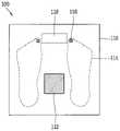
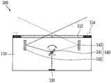
도 1a는 본 발명의 일 실시예에 따른 발 정맥 인증 장치(100) 위에 사용자의 발(10)이 안착된 상태를 나타낸 개념도이고, 도 1b는 도 1a에 도시된 발 정맥 인증 장치(100)를 위에서 바라본 평면도이며, 도 1c는 도 1a에 도시된 센서부(120)에 의해 검출되는 발(10) 내측의 정맥 패턴(P)을 개념적으로 나타낸 도면이고, 도 2는 도 1a에 도시된 발 정맥 인증 장치(100)의 내부 구조를 측면에서 바라본 개념도이며, 도 3은 도 1a에 도시된 발 정맥 인증 장치(100)의 구성을 개념적으로 나타낸 도면이다.1A is a conceptual diagram showing a state in which a user's
도 1a 내지 도 3을 참조하면, 발 정맥 인증 장치(100)는, 바디부(110), 센서부(120) 및 제어부(130)를 포함한다.Referring to FIGS. 1A to 3 , the foot
바디부(110)는, 전면과 후면을 구비하며, 상기 전면 상에 사용자의 발(10)이 안착 가능하도록 형성된다. 또한, 상기 바디부(110)의 전면에는 사용자의 왼발(10a)과 오른발(10b)이 각각 안착될 수 있다. 바디부(110)의 형상은 체중계(scale)와 유사한 형태로 이루어질 수 있다. 또한, 바디부(110)의 상기 전면에는 사용자에게 제공되는 정보들을 출력하는 디스플레이부(118)가 배치될 수 있다.The
센서부(120)는, 상기 바디부(110)의 어느 일 영역에 배치되어, 도 1c에 도시된 바와 같이 사용자의 발(10) 내측의 정맥(vein) 패턴(P)을 검출하도록 구성된다. 또한, 상기 정맥 패턴(P)은, 사용자의 왼발(10a), 오른발(10b)의 정맥 혈관이 서로 다른게 형성되어, 사용자의 왼발(10a) 또는 오른발(10b) 내측에 각각 대응되는 제1 및 제2 정맥 패턴으로 이루어질 수 있다. 또한, 센서부(120)는 상기 제1 및 제2 정맥 패턴을 각각 검출하도록 이루어지는 제1 및 제2 센서(120a,120b)를 구비할 수 있다.The
상기 센서부(120)는, 정맥 패턴(P)을 검출하기 위하여, 도 3에 도시된 바와 같이 광원부(121)와 영상 획득부(122)를 포함한다.The
광원부(121)는, 사용자의 발(10) 내측 즉, 사용자의 발(10)이 바디부(110)의 전면 상에 안착된 상태에서 외부로 노출되는 사용자의 발(10) 안쪽 영역에 적외선(infrared ray)을 조사하도록 구성된다. 예를 들어, 광원부(121)는, 적외선을 발생시키는 IR LED(미도시)로 구성될 수 있으며, 상기 IR LED는 복수로 이루어질 수 있다.The
영상 획득부(122)는, 상기 적외선이 조사된 사용자의 발(10) 내측의 정맥 패턴(P)을 영상으로 획득하여 제어부(130)로 전달하도록 이루어진다. 영상 획득부(122)로 입사되는 광의 경로 상에는, 상기 적외선이 조사된 정맥 혈관을 투시 촬영 가능하도록, 적외선 필터(122a)가 배치될 수 있다.The
제어부(130)는, 센서부(120)로부터 전달받은 상기 정맥 패턴(P)을 기저장된 사용자의 정맥 패턴(P)과 비교하여 사용자 인증 절차를 수행하도록 구성된다. 제어부(130)에는, 센서부(120)로부터 전달받은 상기 정맥 패턴(P)의 사용자 인증 절차와 관련된 연산 처리를 수행하는 중앙처리장치(131)와, 전달받은 정맥 패턴(P)의 특성을 저장한 다음 이후 등록된 사용자 정맥 패턴(P)과 비교하기 위한 메모리(132)가 구비된다. 또한, 제어부(130)는 외부 컴퓨터(E) 장치와 연결되어, 정맥 패턴(P)을 이용하여 사용자 인증 절차를 수행한 결과 등을 상기 외부 컴퓨터(E)로 전달 가능하도록 구성될 수 있다. 또한, 센서부(130)와 제어부(130)는, 센서부(120), 제어부(130) 및 상기 외부 컴퓨터(E)를 서로 연결하여 데이터 및 제어 신호의 전달을 위한 통로 역할을 수행하는 인터페이스부(120a,130a,130b)를 각각 구비할 수 있다. 또한, 제어부(130)는, 상기 제1 및 제2 센서(120a,120b)로부터 전달받은 상기 제1 및 제2 정맥 패턴을 기저장된 사용자의 정맥 패턴(P)과 비교하여 사용자 인증 절차를 수행하도록 구성될 수 있다.The
또한, 제어부(130)는, 제1 센서(120a)로부터 전달받은 상기 제1 정맥 패턴을 이용하여 사용자 인증 절차를 수행하고, 상기 사용자 인증 절차가 상기 정맥 패턴(P)의 인식 오류 등의 문제로 실패하는 경우, 제2 센서(120b)로부터 상기 제2 정맥 패턴을 전달받아 상기 사용자 인증 절차를 다시 수행하도록 구성될 수 있다. 이에 따라, 서로 다른 상기 제1 및 제2 정맥 패턴에 대하여 인증 절차를 이중으로 수행하여 사용자 인증 절차의 오류를 대비하거나, 사용자 인증 절차의 보안 수준을 강화할 수 있다.In addition, the
또한, 제어부(130)는, 영상 강화부(133)를 구비할 수 있다.In addition, the
영상 강화부(133)는, 센서부(120)에서 검출된 사용자의 발(10) 내측 정맥 패턴(P)을 전달받아, 제어부(130)에서 정맥 패턴(P)을 기저장된 사용자 정맥 패턴(P)과 비교하기 전, 전달받은 정맥 패턴(P)의 특성이 보다 잘 드러나도록 영상을 개선하여 상기 정맥 패턴(P) 인식률을 보다 향상시킬 수 있다.The
또한, 제어부(130)는 광원 제어유닛(124)을 더 포함할 수 있다.In addition, the
광원 제어유닛(124)은, 광원부(121)에서 발생되는 적외선의 광량을 제어하도록 이루어진다. 광원 제어유닛(124)은, 영상 획득부(122)의 노출 시간을 조절하여 적외선의 광량을 제어하도록 구성될 수 있다. 이에 따라, 발 정맥 인식 장치(100)의 주변 공간의 밝기에 변화가 발생하는 경우에도, 센서부(130)로 검출되는 상기 정맥 패턴(P)의 품질을 사용자 인증이 가능한 수준으로 안정되게 유지시킬 수 있다.The light
한편, 센서부(120)는, 도시된 바에 의하면 바디부(110)의 상기 전면 하부에 배치되어, 바디부(110)에 의해 감싸지도록 구성될 수 있다. 또한, 바디부(110)는, 투과층(112)을 구비할 수 있다.On the other hand, the
투과층(112)은, 바디부(110)의 상기 전면에 배치되며, 센서부(120)와 사용자의 발(10) 사이에 광의 이동이 가능하도록, 투광성 재질로 이루어질 수 있다. 투과층(112)은 예를 들어, 유리 또는 투광성 플라스틱으로 구성될 수 있다.The
투과층(112)은, 적외선을 선택적으로 투과시키도록 구성되는 적외선 필터층(미도시)을 구비할 수 있다. 상기 적외선 필터층은 광 투과율이 선택적으로 변화 가능하도록 이루어질 수 있으며, 센서부(120)는, 상기 적외선 필터층의 서로 다른 투과율에 따라 서로 다른 범위의 적외선 영상을 획득하도록 이루어질 수 있다.The
한편, 상기 광원부(121)와, 영상 획득부(122)는, 하나의 바디로 이루어지며, 틸트(tilt) 가능하게 구성될 수 있다. 이에 따라, 광원부(121)와 영상 획득부(122)가 함께 틸트됨에 따라 광원부(121)의 적외선 발생 각도와, 영상 획득부(122)의 정맥 패턴(P) 촬영 각도의 조절이 함께 이루어질 수 있다.Meanwhile, the
또한, 상기 광원부(121) 및 영상 획득부(122)가 함께 상기 틸트되는 각도(A1)는, 바디부(110)의 상기 전면과 수직하는 축(V)을 기준으로 45도 이상 70도 이하의 각도(A1)를 이루도록 조절 가능하게 구성될 수 있다. 이에 따라, 사용자의 전환에 따라 변화하는 발(10) 내측의 위치를 정밀하게 조절하여, 상기 정맥 패턴(P) 인식률을 향상시킬 수 있다.In addition, the angle A1 at which the
한편, 광원부(121)에서 적외선이 발생되는 광 기점(S)은, 상기 투과층(112)과 수직한 방향으로 기설정된 거리(D1)만큼 이격되는 위치에 형성될 수 있다. 상기 광 기점(S)은, 광원부(121)에서 발생되는 적외선의 중심부를 지칭한다.On the other hand, the light origin (S) at which infrared rays are generated in the
예를 들어, 상기 광 기점(S)은, 상기 투과층(112)과 수직한 방향으로 10 mm 이하의 거리 내에서 이격되게 위치할 수 있다. 상기 광 기점(S)의 이러한 배치 구조는, 광원부(121)에서 발생한 적외선이 투과층(112)에 도달한 후, 투과층(112)을 투과하여 사용자의 발(10) 내측으로 진행되지 못하고, 투과층(112)에서 반사되어 바디부(110)의 내부로 들어오는 현상을 줄여, 사용자의 발(10) 내측을 타깃(target)으로 하는 적외선의 조사가 보다 정확하게 이루어질 수 있다.For example, the optical starting points S may be spaced apart from each other within a distance of 10 mm or less in a direction perpendicular to the
한편, 바디부(110)는 가이드부(114)를 더 구비할 수 있다.Meanwhile, the
가이드부(114)는, 사용자의 발(10) 바닥면과 대응되게 형성되어, 사용자의 발(10) 위치를 가이드하도록 구성된다. 또한, 가이드부(114)는, 바디부(110)의 상기 전면 상에서, 가상의 이미지로 구현되어 보여질 수 있으며, 바디부(110)의 상기 전면에 안착되는 사용자의 발(10) 사이즈에 따라 가변적으로 그 형태가 변화되도록 이루어질 수 있다. 또한, 가이드부(114)는 사용자의 발가락에 대응되는 위치에 배치되어 사용자의 심박을 측정하도록 이루어지는 심박 센서(116)를 구비할 수 있다.The
또한, 상기 광원부(121)에서 적외선이 발생되는 광 기점(S)은, 바디부(110)의 상기 전면과 수평한 방향으로 가이드부(114)와 기설정된 거리(D2)만큼 이격되는 위치에 형성될 수 있다. 예를 들어, 상기 광 기점(S)은 상기 가이드부(114)와 35 mm 이상 80 mm 이하 범위 내에서 이격되는 위치에 배치될 수 있다. 또한, 상기 광 기점(S)의 가이드부(114)와의 거리가 조절 가능하도록, 바디부(110)의 상기 전면과 수평되는 방향으로 이동 가능하게 구성될 수 있다.In addition, the light source S at which infrared rays are generated from the
이상에서 설명한 본 발명에 의하면, 우선 센서부(120)가, 사용자의 발(10)이 안착되는 바디부(110)의 일 영역에 배치되어 사용자의 발(10) 내측의 정맥 패턴(P)을 영상으로 획득하도록 구성되며, 제어부(130)는 센서부(120)에서 획득한 정맥 패턴(P)을 기저장된 사용자의 정맥 패턴(P)과 비교하여 사용자 인증 절차를 수행하도록 이루어진다. 이에 따라, 정맥을 이용하는 생체인식 기법의 적용 분야를 보다 확장시켜, 발 정맥 인증 장치(100)의 활용도를 높일 수 있다.According to the present invention described above, first, the
또한, 본 발명은 센서부(120)를 구성하는 광원부(121) 및 영상 획득부(122)가 틸트(tilt) 가능하게 구성되며, 상기 틸트되는 각도(A1)와, 광원부(121)에서 적외선이 발생되는 광 기점(S)의 위치가 특정되어, 사용자의 발(10) 내측의 정맥 패턴(P)이 보다 효과적으로 검출 가능하다는 장점을 갖는다.In addition, in the present invention, the
이하, 도 2에 도시된 발 정맥 인증 장치(100)의 다른 실시예에 대하여 설명한다.Hereinafter, another embodiment of the foot
도 4는 도 2에 도시된 발 정맥 인증 장치(100)의 다른 실시예를 나타낸 개념도이다.FIG. 4 is a conceptual diagram illustrating another embodiment of the foot
도 4를 참조하면, 발 정맥 인증 장치(100)는, 광학계(140)를 더 포함할 수 있다.Referring to FIG. 4 , the foot
광학계(140)는, 광원부(121, 도 3 참조)에서 발생되는 적외선의 광 경로 상에 배치되며, 상기 적외선이 사용자의 양 발(10a,10b, 도 1a 참조) 내측으로 각각 조사되도록, 상기 적외선의 광 경로를 선택적으로 변화시키도록 이루어진다.The
이를 위하여, 광학계(140)는, 회전 거울(141), 제1 거울(142), 제2 거울(143)을 포함할 수 있다.To this end, the
회전 거울(141)은, 회전 가능하게 구성되고, 상기 회전에 따라 광원부(121)에서 발생되는 적외선을 반사시켜 광 경로를 변화시키도록 이루어진다.The
제1 및 제2 거울(142,143)은, 회전 거울(141)에서 반사되어 나오는 상기 적외선을 반사하여, 사용자의 양 발 예를 들어 왼발(10a)과 오른발(10b) 내측으로 각각 향하도록 상기 적외선의 광 경로를 변화시키도록 이루어진다. 이와 같은 광학계(140)의 구성에 의하면, 하나의 센서부(120)를 이용하여 사용자의 양 발(10a,10b)의 제1 및 제2 정맥 패턴을 각각 검출 가능하다는 장점을 갖는다.The first and
이하, 바디부(110)의 상부로 돌출되는 돌출부(119)에 센서부(120)가 배치되는 발 정맥 인증 장치(100)의 다른 실시예에 대하여 설명한다.Hereinafter, another embodiment of the foot
도 5는 도 1a에 도시된 발 정맥 인증 장치(100)의 다른 실시예를 나타낸 개념도이고, 도 6은 도 5에 도시된 발 정맥 인증 장치(100)의 내부 구조를 측면에서 바라본 개념도이다.FIG. 5 is a conceptual diagram illustrating another embodiment of the foot
도 5 및 도 6을 참조하면, 바디부(110)는 돌출부(119)를 더 구비할 수 있다.Referring to FIGS. 5 and 6 , the
바디부(110)는 전면과 후면을 구비하며, 상기 전면 상에는 사용자의 발(10)이 안착될 수 있다.The
돌출부(119)는, 도시된 바와 같이 바디부(110)의 상기 전면의 상부로 돌출되게 형성될 수 있다. 여기서, 센서부(120)는, 상기 돌출부(119) 내부에 배치되어, 돌출부(119)에 의해 감싸지도록 구성될 수 있다. 또한, 돌출부(119)는, 센서부(120)와 사용자의 발(10) 사이에서 광의 이동이 가능하도록, 돌출부(119)의 외면에 배치되며 투광성 재질로 이루어지는 투과층(112)을 구비할 수 있다. 또한, 상기 투과층(112)은, 상기 적외선을 선택적으로 투과시키도록 이루어지는 적외선 필터층(미도시)을 구비할 수 있다.As shown, the protruding
한편, 광원부(121, 도 3 참조) 및 영상 획득부(122, 도3 참조)는, 하나의 바디로 이루어지며, 틸트(tilt) 가능하게 구성될 수 있다. 여기서, 상기 틸트되는 각도(A2)는 바디부(110)의 상기 전면과 수직하는 축(V)을 기준으로 0 도 이상 35 도 이하의 각도(A2)를 이루도록 구성될 수 있다.Meanwhile, the light source unit 121 (see FIG. 3) and the image acquisition unit 122 (see FIG. 3) are made of one body and may be configured to be tiltable. Here, the tilt angle A2 may be configured to form an angle A2 of 0 degrees or more and 35 degrees or less based on an axis V perpendicular to the front surface of the
한편, 광원부(121)에서 적외선이 발생되는 광 기점(S)은, 바디부(110)의 상기 전면과 수직한 방향으로 기설정된 거리(D1)만큼 이격되는 위치에 형성될 수 있다. 예를 들어, 상기 광 기점(S)은 바디부(110)의 상기 전면과 50 mm 이하의 거리 내에서 이격되게 위치할 수 있다.On the other hand, the light source S at which infrared rays are generated from the
한편, 바디부(110)는 가이드부(114)를 더 구비할 수 있다.Meanwhile, the
가이드부(114)는, 사용자의 발(10) 바닥면과 대응되게 형성되며, 사용자의 발(10) 위치를 가이드하도록 구성될 수 있다. 또한, 가이드부(114)는, 바디부(110)의 상기 전면 상에서, 가상의 이미지로 구현되어 보여질 수 있으며, 바디부(110)의 상기 전면에 안착되는 사용자의 발(10) 사이즈에 따라 가변적으로 그 형태가 변화되도록 이루어질 수 있다.The
또한, 광원부(112)에서 적외선이 발생되는 광 기점(S)은, 바디부(110)의 상기 전면과 수평한 방향으로 상기 가이드부(114)와 기설정된 거리(D2)만큼 이격되는 위치에 형성될 수 있다. 예를 들어, 상기 광 기점(S)은, 상기 가이드부(114)와 35 mm 이상 80 mm 이하의 범위 내에서 이격되는 위치에 형성될 수 있다.In addition, the light source S at which infrared rays are generated from the
Claims (21)
Translated fromKorean상기 바디부의 어느 일 영역에 배치되고, 사용자의 발 내측의 정맥 패턴을 검출하도록 구성되는 센서부; 및
상기 센서부로부터 전달받은 상기 정맥 패턴을 기저장된 사용자의 정맥 패턴과 비교하여 사용자 인증 절차를 수행하는 제어부를 포함하고,
상기 센서부는,
상기 사용자의 발 내측으로 적외선을 조사하도록 구성되는 광원부; 및
상기 적외선이 조사된 사용자의 발 내측의 정맥 패턴을 영상으로 획득하여 상기 제어부로 전달하는 영상 획득부를 포함하고,
상기 센서부는 상기 전면의 하부에 배치되어, 상기 바디부에 의해 감싸지도록 구성되고,
상기 바디부는, 상기 센서부와 사용자의 발 사이에서 광의 이동이 가능하도록, 상기 전면에 배치되며 투광성 재질로 이루어지는 투과층을 구비하고,
상기 투과층은, 적외선을 선택적으로 투과시키도록 이루어지는 적외선 필터층을 구비하고,
상기 센서부는 상기 적외선 필터층의 서로 다른 투과율에 따라 서로 다른 범위의 적외선 영상을 획득하는 것을 특징으로 하는 발 정맥 인증 장치.A body portion having front and rear surfaces, on which the user's feet are seated;
a sensor unit disposed in an area of the body unit and configured to detect a vein pattern inside the user's foot; and
And a control unit for performing a user authentication procedure by comparing the vein pattern received from the sensor unit with a pre-stored vein pattern of a user,
The sensor unit,
a light source unit configured to irradiate infrared rays toward the inside of the user's feet; and
An image acquisition unit for obtaining an image of a vein pattern on the inner side of the foot of the user irradiated with the infrared rays and transmitting the image to the control unit;
The sensor unit is disposed below the front surface and is configured to be surrounded by the body unit,
The body part has a transmission layer disposed on the front surface and made of a light-transmitting material so that light can move between the sensor part and the user's foot,
The transmission layer includes an infrared filter layer configured to selectively transmit infrared rays,
The sensor unit acquires infrared images of different ranges according to different transmittances of the infrared filter layer.
상기 광원부 및 상기 영상 획득부는 하나의 바디로 이루어지며, 틸트되는 것이 가능하게 구성되고,
상기 틸트되는 각도는 상기 전면과 수직하는 축을 기준으로 45도 이상 70도 이하의 각도를 이루도록 구성되어 상기 광원부 및 상기 영상 획득부가 함께 틸트됨에 따라 상기 광원부의 적외선 발생 각도와 상기 영상 획득부의 정맥 패턴 촬영 각도의 조절이 함께 이루어지는 것을 특징으로 하는 발 정맥 인증 장치.According to claim 1,
The light source unit and the image acquisition unit are made of one body and are configured to be tilted,
The tilted angle is configured to form an angle of 45 degrees or more and 70 degrees or less based on an axis perpendicular to the front surface, and as the light source unit and the image acquisition unit are tilted together, the infrared generation angle of the light source unit and the vein pattern of the image acquisition unit are captured Foot vein authentication device, characterized in that the angle is adjusted together.
상기 광원부에서 적외선이 발생되는 광 기점은, 상기 투과층과 수직한 방향으로 기설정된 거리만큼 이격되는 위치에 형성되는 것을 특징으로 하는 발 정맥 인증 장치.According to claim 1,
Foot vein authentication device, characterized in that the light origin from the light source unit is formed at a position spaced apart by a predetermined distance in a direction perpendicular to the transmission layer.
상기 광 기점은, 상기 투과층과 수직한 방향으로 10 mm 이하의 거리 내에서 이격되게 위치하는 것을 특징으로 하는 발 정맥 인증 장치.According to claim 6,
The foot vein authentication device, characterized in that the optical starting point is located apart from each other within a distance of 10 mm or less in a direction perpendicular to the transmission layer.
상기 바디부는, 사용자의 발 바닥면과 대응되게 형성되어, 사용자의 발 위치를 가이드하는 가이드부를 더 구비하는 것을 특징으로 하는 발 정맥 인증 장치.According to claim 1,
The body part further comprises a guide part formed to correspond to the bottom surface of the user's foot and guiding the position of the user's foot.
상기 광원부에서 적외선이 발생되는 광 기점은, 상기 전면과 수평한 방향으로 상기 가이드부와 기설정된 거리만큼 이격되는 위치에 형성되는 것을 특징으로 하는 발 정맥 인증 장치.According to claim 8,
Foot vein authentication device, characterized in that the optical origin at which the infrared rays are generated from the light source is formed at a position spaced apart from the guide by a predetermined distance in a direction horizontal to the front surface.
상기 센서부는, 상기 광원부에서 발생되는 적외선의 광량을 제어하는 광원 제어유닛을 더 포함하는 것을 특징으로 하는 발 정맥 인증 장치.According to claim 1,
The sensor unit further comprises a light source control unit that controls the amount of infrared light generated by the light source unit.
상기 센서부는, 사용자의 양 발 내측에 각각 대응되는 제1 정맥 패턴 및 제2 정맥 패턴을 검출하도록 이루어지는 제1 센서 및 제2 센서를 구비하고,
상기 제어부는, 상기 제1 센서 및 제2 센서로부터 전달받은 상기 제1 정맥 패턴 및 제2 정맥 패턴을 기저장된 사용자의 정맥 패턴과 비교하여 사용자 인증 절차를 수행하도록 구성되는 것을 특징으로 하는 발 정맥 인증 장치.According to claim 1,
The sensor unit includes a first sensor and a second sensor configured to detect a first vein pattern and a second vein pattern respectively corresponding to the inside of both feet of the user,
Wherein the control unit is configured to perform a user authentication procedure by comparing the first vein pattern and the second vein pattern transmitted from the first sensor and the second sensor with a pre-stored vein pattern of the user. Device.
상기 제어부는, 상기 제1 센서로부터 전달받은 상기 제1 정맥 패턴을 이용하여 사용자 인증 절차의 수행하고, 상기 사용자 인증 절차가 실패하는 경우, 상기 제2 센서로부터 상기 제2 정맥 패턴을 전달받아 상기 사용자 인증 절차를 다시 수행하도록 구성되는 것을 특징으로 하는 발 정맥 인증 장치.According to claim 11,
The control unit performs a user authentication procedure using the first vein pattern transmitted from the first sensor, and when the user authentication procedure fails, receives the second vein pattern from the second sensor and performs the user authentication procedure. A foot vein authentication device, characterized in that it is configured to perform the authentication procedure again.
상기 광원부에서 발생되는 적외선의 광 경로 상에 배치되고, 상기 적외선이 사용자의 양 발 내측으로 각각 조사되도록, 상기 적외선의 광 경로를 선택적으로 변화시키는 광학계를 더 포함하고,
상기 광학계는,
회전 가능하게 구성되며, 상기 회전에 따라 상기 광원부에서 발생되는 적외선을 반사시켜 광 경로를 변화시키는 회전 거울; 및
상기 회전 거울에서 반사되어 나오는 적외선을 반사하여, 사용자의 양 발 내측으로 각각 향하도록 상기 적외선의 광 경로를 변화시키는 제1 및 제2 거울을 포함하는 것을 특징으로 하는 발 정맥 인증 장치.According to claim 1,
An optical system disposed on a light path of the infrared light generated from the light source unit and selectively changing the light path of the infrared light so that the infrared light is irradiated to the inside of both feet of the user, respectively;
The optical system,
a rotating mirror configured to be rotatable and change an optical path by reflecting infrared rays generated from the light source unit according to the rotation; and
and first and second mirrors that reflect the infrared rays reflected from the rotating mirror and change optical paths of the infrared rays so that the infrared rays are directed toward the inner side of both feet of the user.
상기 제어부는, 상기 센서부로부터 전달받은 상기 정맥 패턴의 영상을 개선시키도록 구성되는 영상 강화부를 구비하는 것을 특징으로 하는 발 정맥 인증 장치.According to claim 1,
The control unit comprises an image enhancement unit configured to improve the image of the vein pattern transmitted from the sensor unit.
상기 바디부는, 상기 전면의 상부로 돌출되는 돌출부를 더 구비하며,
상기 센서부는 상기 돌출부 내부에 배치되어, 상기 돌출부에 의해 감싸지도록 구성되고,
상기 돌출부는, 외면에 배치되며 상기 센서부와 사용자의 발 사이에서 광의 이동이 가능하도록, 투광성 재질로 이루어지는 투과층을 구비하는 것을 특징으로 하는 발 정맥 인증 장치.According to claim 1,
The body portion further includes a protrusion protruding upward from the front surface,
The sensor unit is disposed inside the protrusion and is configured to be surrounded by the protrusion,
The protrusion is disposed on an outer surface and includes a transmission layer made of a light-transmitting material so that light can move between the sensor unit and the user's foot.
상기 투과층은, 적외선을 선택적으로 투과시키도록 이루어지는 적외선 필터층을 구비하는 것을 특징으로 하는 발 정맥 인증 장치.According to claim 15,
The transmission layer includes an infrared filter layer configured to selectively transmit infrared rays.
상기 광원부 및 상기 영상 획득부는 하나의 바디로 이루어지며, 틸트되는 것이 가능하게 구성되는 것을 특징으로 하는 발 정맥 인증 장치.According to claim 15,
The light source unit and the image acquisition unit are made of one body, and the foot vein authentication device, characterized in that configured to be tilted.
상기 틸트되는 각도는 상기 전면과 수직하는 축을 기준으로 0도 이상 35도 이하의 각도를 이루도록 구성되는 것을 특징으로 하는 발 정맥 인증 장치.According to claim 17,
The tilted angle is configured to form an angle of 0 degrees or more and 35 degrees or less based on an axis perpendicular to the front surface.
상기 광원부에서 적외선이 발생되는 광 기점은, 상기 전면과 수직한 방향으로 기설정된 거리만큼 이격되는 위치에 형성되는 것을 특징으로 하는 발 정맥 인증 장치.According to claim 15,
Foot vein authentication device, characterized in that the light origin at which the infrared rays are generated from the light source is formed at a position spaced apart by a predetermined distance in a direction perpendicular to the front surface.
상기 바디부는, 사용자의 발 바닥면과 대응되게 형성되어, 사용자의 발 위치를 가이드하는 가이드부를 더 구비하는 것을 특징으로 하는 발 정맥 인증 장치.According to claim 15,
The body part further comprises a guide part formed to correspond to the bottom surface of the user's foot and guiding the position of the user's foot.
상기 광원부에서 적외선이 발생되는 광 기점은, 상기 전면과 수평한 방향으로 기설정된 거리만큼 이격되는 위치에 형성되는 것을 특징으로 하는 발 정맥 인증 장치.According to claim 20,
Foot vein authentication device, characterized in that the light origin from the light source unit is formed at a position spaced apart from the front surface by a predetermined distance in a horizontal direction.
Priority Applications (3)
| Application Number | Priority Date | Filing Date | Title |
|---|---|---|---|
| KR1020160024504AKR102468133B1 (en) | 2016-02-29 | 2016-02-29 | Foot vein authentication device |
| US16/079,503US10635885B2 (en) | 2016-02-29 | 2016-03-09 | Foot vein authentication device |
| PCT/KR2016/002309WO2017150754A1 (en) | 2016-02-29 | 2016-03-09 | Foot vein authentication device |
Applications Claiming Priority (1)
| Application Number | Priority Date | Filing Date | Title |
|---|---|---|---|
| KR1020160024504AKR102468133B1 (en) | 2016-02-29 | 2016-02-29 | Foot vein authentication device |
Publications (2)
| Publication Number | Publication Date |
|---|---|
| KR20170101665A KR20170101665A (en) | 2017-09-06 |
| KR102468133B1true KR102468133B1 (en) | 2022-11-18 |
Family
ID=59743056
Family Applications (1)
| Application Number | Title | Priority Date | Filing Date |
|---|---|---|---|
| KR1020160024504AActiveKR102468133B1 (en) | 2016-02-29 | 2016-02-29 | Foot vein authentication device |
Country Status (3)
| Country | Link |
|---|---|
| US (1) | US10635885B2 (en) |
| KR (1) | KR102468133B1 (en) |
| WO (1) | WO2017150754A1 (en) |
Families Citing this family (2)
| Publication number | Priority date | Publication date | Assignee | Title |
|---|---|---|---|---|
| US10449980B1 (en)* | 2018-05-02 | 2019-10-22 | International Business Machines Corporation | Providing an alert to a passenger based on a location of the passenger while in transit on a multi-passenger mode of transport |
| US12419521B2 (en) | 2020-08-21 | 2025-09-23 | Empo Health, Inc. | System to detect foot abnormalities |
Citations (1)
| Publication number | Priority date | Publication date | Assignee | Title |
|---|---|---|---|---|
| US20080075332A1 (en)* | 2006-09-25 | 2008-03-27 | Yasunori Fujisawa | Finger vein pattern inputting device |
Family Cites Families (61)
| Publication number | Priority date | Publication date | Assignee | Title |
|---|---|---|---|---|
| US5131412A (en)* | 1991-08-26 | 1992-07-21 | Ellen Rankin | Pediatric intravenous device |
| US5899863A (en)* | 1997-05-07 | 1999-05-04 | General Electric Company | Method and apparatus for segmenting B-mode intensity data using doppler shift data in three-dimensional ultrasound imaging |
| US5924987A (en)* | 1997-10-06 | 1999-07-20 | Meaney; James F. M. | Method and apparatus for magnetic resonance arteriography using contrast agents |
| JP2001258851A (en)* | 2000-03-17 | 2001-09-25 | Canon Inc | Ophthalmic imaging apparatus and color balance adjustment method |
| EP2098977B1 (en)* | 2002-05-09 | 2012-11-21 | Sony Corporation | Method of detecting biological pattern, biological pattern detector, method of biological certificate and biological certificate apparatus |
| US9208505B1 (en) | 2002-10-01 | 2015-12-08 | Tiger T G Zhou | Systems and methods for providing compensation, rebate, cashback, and reward for using mobile and wearable payment services |
| CA2597675C (en)* | 2005-02-16 | 2013-05-14 | Orica Explosives Technology Pty Ltd | Security enhanced blasting apparatus with biometric analyzer and method of blasting |
| US8971984B2 (en)* | 2005-04-04 | 2015-03-03 | Hypermed Imaging, Inc. | Hyperspectral technology for assessing and treating diabetic foot and tissue disease |
| KR101008789B1 (en) | 2005-06-13 | 2011-01-14 | 가부시키가이샤 히타치세이사쿠쇼 | Vein authentication device |
| WO2007001025A1 (en)* | 2005-06-29 | 2007-01-04 | Kyocera Corporation | Biometric recognition system |
| US20070038118A1 (en)* | 2005-08-10 | 2007-02-15 | Depue Marshall Thomas | Subcutaneous tissue imager |
| US8489178B2 (en)* | 2006-06-29 | 2013-07-16 | Accuvein Inc. | Enhanced laser vein contrast enhancer with projection of analyzed vein data |
| JP4725385B2 (en)* | 2006-03-24 | 2011-07-13 | ソニー株式会社 | Mobile phone and electronic device |
| US20120035540A1 (en)* | 2006-04-12 | 2012-02-09 | Searete Llc, A Limited Liability Corporation Of The State Of Delaware | Event-based control of a lumen traveling device |
| US20080005578A1 (en)* | 2006-06-29 | 2008-01-03 | Innovya Research & Development Ltd. | System and method for traceless biometric identification |
| KR100801088B1 (en)* | 2006-10-02 | 2008-02-05 | 삼성전자주식회사 | How to create a focus-free image and an out-of-focus image using the multi focus camera device and the multi focus camera device |
| US20080107309A1 (en)* | 2006-11-03 | 2008-05-08 | Cerni Consulting, Llc | Method and apparatus for biometric identification |
| JP4306744B2 (en)* | 2007-03-01 | 2009-08-05 | ソニー株式会社 | Biometric authentication device |
| KR101096984B1 (en)* | 2007-03-29 | 2011-12-22 | 후지쯔 가부시끼가이샤 | Imaging device, imaging method, and computer readable recording medium having imaging program |
| JP4407714B2 (en)* | 2007-04-06 | 2010-02-03 | セイコーエプソン株式会社 | Biometric authentication device and biometric authentication method |
| KR20100033371A (en)* | 2007-05-07 | 2010-03-29 | 주식회사 이노제스트 | Apparatus and method for recognizing subcutaneous vein pattern |
| US20080317293A1 (en)* | 2007-06-22 | 2008-12-25 | Soichi Sakurai | Finger vein authentication apparatus and information processing apparatus |
| JP5034713B2 (en)* | 2007-06-28 | 2012-09-26 | 株式会社日立製作所 | Finger vein authentication device and information processing device |
| US20100277314A1 (en)* | 2007-11-08 | 2010-11-04 | Gabriel Bradley | Alarm apparatus |
| US9672471B2 (en)* | 2007-12-18 | 2017-06-06 | Gearbox Llc | Systems, devices, and methods for detecting occlusions in a biological subject including spectral learning |
| US8280484B2 (en)* | 2007-12-18 | 2012-10-02 | The Invention Science Fund I, Llc | System, devices, and methods for detecting occlusions in a biological subject |
| US20090161920A1 (en)* | 2007-12-25 | 2009-06-25 | Hitachi Maxell, Ltd. | Biometric information acquisition apparatus, image acquisition apparatus, and electronic equipment |
| JP5438673B2 (en)* | 2008-04-21 | 2014-03-12 | パナソニック株式会社 | Interchangeable lens, camera body, camera system |
| US9101537B2 (en)* | 2008-07-25 | 2015-08-11 | Reven Pharmaceuticals, Inc. | Compositions and methods for the prevention and treatment of cardiovascular diseases |
| JP5079675B2 (en)* | 2008-12-08 | 2012-11-21 | 日立マクセル株式会社 | Biometric information acquisition device, biometric authentication device, light guide, and image acquisition device |
| FR2946774B1 (en)* | 2009-06-16 | 2012-03-23 | Sagem Securite | IMAGING DEVICE WITH PRISMATIC ELEMENT. |
| KR20120074358A (en)* | 2010-12-28 | 2012-07-06 | 삼성전자주식회사 | Biometric authentication system |
| US20120194662A1 (en)* | 2011-01-28 | 2012-08-02 | The Hong Kong Polytechnic University | Method and system for multispectral palmprint verification |
| EP2495687B1 (en)* | 2011-03-02 | 2018-12-05 | Precise Biometrics AB | Method of matching, biometric matching apparatus, and computer program |
| JP2012245083A (en)* | 2011-05-26 | 2012-12-13 | Seiko Epson Corp | Imaging device, biometric authentication device, electronic equipment |
| US8850536B2 (en)* | 2011-08-05 | 2014-09-30 | Safefaces LLC | Methods and systems for identity verification in a social network using ratings |
| US8850535B2 (en)* | 2011-08-05 | 2014-09-30 | Safefaces LLC | Methods and systems for identity verification in a social network using ratings |
| JP5926909B2 (en)* | 2011-09-07 | 2016-05-25 | オリンパス株式会社 | Fluorescence observation equipment |
| JP6005918B2 (en)* | 2011-09-08 | 2016-10-12 | オリンパス株式会社 | Fluorescence observation equipment |
| US9323912B2 (en)* | 2012-02-28 | 2016-04-26 | Verizon Patent And Licensing Inc. | Method and system for multi-factor biometric authentication |
| US9100825B2 (en)* | 2012-02-28 | 2015-08-04 | Verizon Patent And Licensing Inc. | Method and system for multi-factor biometric authentication based on different device capture modalities |
| CA2874401A1 (en)* | 2012-05-29 | 2013-12-05 | National University Corporation Kochi University | Artery visualization device and artery imaging device |
| US8483450B1 (en)* | 2012-08-10 | 2013-07-09 | EyeVerify LLC | Quality metrics for biometric authentication |
| US9955900B2 (en)* | 2012-10-31 | 2018-05-01 | Quaerimus, Inc. | System and method for continuous monitoring of a human foot |
| US9901298B2 (en)* | 2012-11-01 | 2018-02-27 | Quaerimus Medical Incorporated | System and method for prevention of diabetic foot ulcers using total internal reflection imaging |
| US9602483B2 (en)* | 2013-08-08 | 2017-03-21 | Google Technology Holdings LLC | Adaptive method for biometrically certified communication |
| WO2015126095A1 (en)* | 2014-02-21 | 2015-08-27 | 삼성전자 주식회사 | Electronic device |
| WO2015145590A1 (en)* | 2014-03-25 | 2015-10-01 | 富士通フロンテック株式会社 | Biometric authentication device, biometric authentication method, and program |
| WO2015145591A1 (en)* | 2014-03-25 | 2015-10-01 | 富士通フロンテック株式会社 | Biometric authentication device, biometric authentication method, and program |
| JP6481269B2 (en)* | 2014-07-01 | 2019-03-13 | 富士通株式会社 | Output control method, image processing apparatus, output control program, and information processing apparatus |
| WO2016017970A1 (en)* | 2014-07-31 | 2016-02-04 | Samsung Electronics Co., Ltd. | Method and device for encrypting or decrypting content |
| KR20170041872A (en)* | 2014-08-11 | 2017-04-17 | 더 보오드 오브 트러스티스 오브 더 유니버시티 오브 일리노이즈 | Epidermal devices for analysis of temperature and thermal transport characteristics |
| JP2016150130A (en)* | 2015-02-18 | 2016-08-22 | セイコーエプソン株式会社 | Information acquisition device and information acquisition method |
| US10201425B2 (en)* | 2015-03-02 | 2019-02-12 | Georgia Tech Research Corporation | Implantable open vein valve |
| US9654605B2 (en)* | 2015-03-04 | 2017-05-16 | Otter Products, Llc | Accessory for use with electronic device and cover |
| US10002242B2 (en)* | 2015-08-17 | 2018-06-19 | Qualcomm Incorporated | Electronic device access control using biometric technologies |
| JP6679897B2 (en)* | 2015-11-20 | 2020-04-15 | 富士通株式会社 | Information processing device, biometric authentication method, and biometric authentication program |
| US20170206332A1 (en)* | 2016-01-14 | 2017-07-20 | Carmen Piccin | Biometric-Medical Emergency Data System, Med+ Card, and 911 Mobile Application |
| JP6696246B2 (en)* | 2016-03-16 | 2020-05-20 | 富士ゼロックス株式会社 | Image processing device and program |
| KR102742777B1 (en)* | 2016-08-12 | 2024-12-16 | 삼성전자주식회사 | Optical lens assembly and electronic apparatus having the same |
| KR102483642B1 (en)* | 2016-08-23 | 2023-01-02 | 삼성전자주식회사 | Method and apparatus for liveness test |
- 2016
- 2016-02-29KRKR1020160024504Apatent/KR102468133B1/enactiveActive
- 2016-03-09USUS16/079,503patent/US10635885B2/enactiveActive
- 2016-03-09WOPCT/KR2016/002309patent/WO2017150754A1/ennot_activeCeased
Patent Citations (1)
| Publication number | Priority date | Publication date | Assignee | Title |
|---|---|---|---|---|
| US20080075332A1 (en)* | 2006-09-25 | 2008-03-27 | Yasunori Fujisawa | Finger vein pattern inputting device |
Also Published As
| Publication number | Publication date |
|---|---|
| US10635885B2 (en) | 2020-04-28 |
| KR20170101665A (en) | 2017-09-06 |
| WO2017150754A1 (en) | 2017-09-08 |
| US20190050627A1 (en) | 2019-02-14 |
Similar Documents
| Publication | Publication Date | Title |
|---|---|---|
| US10264998B2 (en) | Blood vessel imaging apparatus and personal authentication system | |
| US10119806B2 (en) | Information processing apparatus and information processing method | |
| CN103929566B (en) | Biometric information image capture apparatus and biometrics authentication apparatus | |
| US20240315563A1 (en) | System and method for eye tracking | |
| US20090016574A1 (en) | Biometric discrimination device, authentication device, and biometric discrimination method | |
| US20130329031A1 (en) | Blood vessel image pickup device, and organism authentication device | |
| US20080111054A1 (en) | System, method and medium tracking motion | |
| WO2014200589A9 (en) | Determining positional information for an object in space | |
| TWI850517B (en) | Liveness detection module, device, system and method | |
| WO2020041987A1 (en) | Biometric recognition apparatus and method, and electronic device | |
| KR102468133B1 (en) | Foot vein authentication device | |
| US20040120553A1 (en) | Device for contactless optical acquisition of biometric characteristics of at least one body part | |
| US11899764B2 (en) | Information processing apparatus and non-transitory computer readable medium for selecting presentation location of target image formed in air | |
| EP3721381B1 (en) | Anti-spoofing face id sensing | |
| KR102713797B1 (en) | Photographic devices and authentication devices | |
| JP6555707B2 (en) | Pupil detection device, pupil detection method, and pupil detection program | |
| JP2007159762A (en) | Distance measuring device for biometric authentication device and biometric authentication device | |
| CN112154443B (en) | Optical fingerprint sensor with folded optical path | |
| JP2018081469A (en) | Blood vessel image pickup apparatus and personal authentication system | |
| KR102846619B1 (en) | Biometric device using finger vein features and finger shape | |
| KR102473523B1 (en) | Iris recognition method and device | |
| US20230410548A1 (en) | Imaging apparatus and imaging method | |
| KR20150139381A (en) | Apparatus for recognizing iris and operating method thereof |
Legal Events
| Date | Code | Title | Description |
|---|---|---|---|
| PA0109 | Patent application | Patent event code:PA01091R01D Comment text:Patent Application Patent event date:20160229 | |
| PG1501 | Laying open of application | ||
| A201 | Request for examination | ||
| PA0201 | Request for examination | Patent event code:PA02012R01D Patent event date:20210125 Comment text:Request for Examination of Application Patent event code:PA02011R01I Patent event date:20160229 Comment text:Patent Application | |
| E902 | Notification of reason for refusal | ||
| PE0902 | Notice of grounds for rejection | Comment text:Notification of reason for refusal Patent event date:20220515 Patent event code:PE09021S01D | |
| E701 | Decision to grant or registration of patent right | ||
| PE0701 | Decision of registration | Patent event code:PE07011S01D Comment text:Decision to Grant Registration Patent event date:20221101 | |
| GRNT | Written decision to grant | ||
| PR0701 | Registration of establishment | Comment text:Registration of Establishment Patent event date:20221114 Patent event code:PR07011E01D | |
| PR1002 | Payment of registration fee | Payment date:20221115 End annual number:3 Start annual number:1 | |
| PG1601 | Publication of registration |