KR102468100B1 - Liquid processing apparatus - Google Patents
Liquid processing apparatusDownload PDFInfo
- Publication number
- KR102468100B1 KR102468100B1KR1020180012647AKR20180012647AKR102468100B1KR 102468100 B1KR102468100 B1KR 102468100B1KR 1020180012647 AKR1020180012647 AKR 1020180012647AKR 20180012647 AKR20180012647 AKR 20180012647AKR 102468100 B1KR102468100 B1KR 102468100B1
- Authority
- KR
- South Korea
- Prior art keywords
- liquid
- substrate
- liquid supply
- nozzle
- wafer
- Prior art date
- Legal status (The legal status is an assumption and is not a legal conclusion. Google has not performed a legal analysis and makes no representation as to the accuracy of the status listed.)
- Active
Links
Images


Classifications
- H—ELECTRICITY
- H01—ELECTRIC ELEMENTS
- H01L—SEMICONDUCTOR DEVICES NOT COVERED BY CLASS H10
- H01L21/00—Processes or apparatus adapted for the manufacture or treatment of semiconductor or solid state devices or of parts thereof
- H01L21/67—Apparatus specially adapted for handling semiconductor or electric solid state devices during manufacture or treatment thereof; Apparatus specially adapted for handling wafers during manufacture or treatment of semiconductor or electric solid state devices or components ; Apparatus not specifically provided for elsewhere
- H01L21/67005—Apparatus not specifically provided for elsewhere
- H01L21/67011—Apparatus for manufacture or treatment
- H01L21/67017—Apparatus for fluid treatment
- H01L21/67028—Apparatus for fluid treatment for cleaning followed by drying, rinsing, stripping, blasting or the like
- H01L21/6704—Apparatus for fluid treatment for cleaning followed by drying, rinsing, stripping, blasting or the like for wet cleaning or washing
- H01L21/67051—Apparatus for fluid treatment for cleaning followed by drying, rinsing, stripping, blasting or the like for wet cleaning or washing using mainly spraying means, e.g. nozzles
- H—ELECTRICITY
- H01—ELECTRIC ELEMENTS
- H01L—SEMICONDUCTOR DEVICES NOT COVERED BY CLASS H10
- H01L21/00—Processes or apparatus adapted for the manufacture or treatment of semiconductor or solid state devices or of parts thereof
- H01L21/67—Apparatus specially adapted for handling semiconductor or electric solid state devices during manufacture or treatment thereof; Apparatus specially adapted for handling wafers during manufacture or treatment of semiconductor or electric solid state devices or components ; Apparatus not specifically provided for elsewhere
- H01L21/67005—Apparatus not specifically provided for elsewhere
- H01L21/67011—Apparatus for manufacture or treatment
- H01L21/67017—Apparatus for fluid treatment
- H01L21/67063—Apparatus for fluid treatment for etching
- H01L21/67075—Apparatus for fluid treatment for etching for wet etching
- H01L21/6708—Apparatus for fluid treatment for etching for wet etching using mainly spraying means, e.g. nozzles
- H—ELECTRICITY
- H01—ELECTRIC ELEMENTS
- H01L—SEMICONDUCTOR DEVICES NOT COVERED BY CLASS H10
- H01L21/00—Processes or apparatus adapted for the manufacture or treatment of semiconductor or solid state devices or of parts thereof
- H01L21/67—Apparatus specially adapted for handling semiconductor or electric solid state devices during manufacture or treatment thereof; Apparatus specially adapted for handling wafers during manufacture or treatment of semiconductor or electric solid state devices or components ; Apparatus not specifically provided for elsewhere
- H01L21/67005—Apparatus not specifically provided for elsewhere
- H01L21/67011—Apparatus for manufacture or treatment
- H01L21/67017—Apparatus for fluid treatment
- H01L21/67028—Apparatus for fluid treatment for cleaning followed by drying, rinsing, stripping, blasting or the like
- H01L21/67034—Apparatus for fluid treatment for cleaning followed by drying, rinsing, stripping, blasting or the like for drying
- H—ELECTRICITY
- H01—ELECTRIC ELEMENTS
- H01L—SEMICONDUCTOR DEVICES NOT COVERED BY CLASS H10
- H01L21/00—Processes or apparatus adapted for the manufacture or treatment of semiconductor or solid state devices or of parts thereof
- H01L21/67—Apparatus specially adapted for handling semiconductor or electric solid state devices during manufacture or treatment thereof; Apparatus specially adapted for handling wafers during manufacture or treatment of semiconductor or electric solid state devices or components ; Apparatus not specifically provided for elsewhere
- H01L21/67005—Apparatus not specifically provided for elsewhere
- H01L21/67011—Apparatus for manufacture or treatment
- H01L21/6715—Apparatus for applying a liquid, a resin, an ink or the like
- H—ELECTRICITY
- H01—ELECTRIC ELEMENTS
- H01L—SEMICONDUCTOR DEVICES NOT COVERED BY CLASS H10
- H01L21/00—Processes or apparatus adapted for the manufacture or treatment of semiconductor or solid state devices or of parts thereof
- H01L21/67—Apparatus specially adapted for handling semiconductor or electric solid state devices during manufacture or treatment thereof; Apparatus specially adapted for handling wafers during manufacture or treatment of semiconductor or electric solid state devices or components ; Apparatus not specifically provided for elsewhere
- H01L21/683—Apparatus specially adapted for handling semiconductor or electric solid state devices during manufacture or treatment thereof; Apparatus specially adapted for handling wafers during manufacture or treatment of semiconductor or electric solid state devices or components ; Apparatus not specifically provided for elsewhere for supporting or gripping
- H01L21/687—Apparatus specially adapted for handling semiconductor or electric solid state devices during manufacture or treatment thereof; Apparatus specially adapted for handling wafers during manufacture or treatment of semiconductor or electric solid state devices or components ; Apparatus not specifically provided for elsewhere for supporting or gripping using mechanical means, e.g. chucks, clamps or pinches
- H01L21/68714—Apparatus specially adapted for handling semiconductor or electric solid state devices during manufacture or treatment thereof; Apparatus specially adapted for handling wafers during manufacture or treatment of semiconductor or electric solid state devices or components ; Apparatus not specifically provided for elsewhere for supporting or gripping using mechanical means, e.g. chucks, clamps or pinches the wafers being placed on a susceptor, stage or support
- H01L21/68764—Apparatus specially adapted for handling semiconductor or electric solid state devices during manufacture or treatment thereof; Apparatus specially adapted for handling wafers during manufacture or treatment of semiconductor or electric solid state devices or components ; Apparatus not specifically provided for elsewhere for supporting or gripping using mechanical means, e.g. chucks, clamps or pinches the wafers being placed on a susceptor, stage or support characterised by a movable susceptor, stage or support, others than those only rotating on their own vertical axis, e.g. susceptors on a rotating caroussel
- H—ELECTRICITY
- H01—ELECTRIC ELEMENTS
- H01L—SEMICONDUCTOR DEVICES NOT COVERED BY CLASS H10
- H01L21/00—Processes or apparatus adapted for the manufacture or treatment of semiconductor or solid state devices or of parts thereof
- H01L21/67—Apparatus specially adapted for handling semiconductor or electric solid state devices during manufacture or treatment thereof; Apparatus specially adapted for handling wafers during manufacture or treatment of semiconductor or electric solid state devices or components ; Apparatus not specifically provided for elsewhere
- H01L21/683—Apparatus specially adapted for handling semiconductor or electric solid state devices during manufacture or treatment thereof; Apparatus specially adapted for handling wafers during manufacture or treatment of semiconductor or electric solid state devices or components ; Apparatus not specifically provided for elsewhere for supporting or gripping
- H01L21/687—Apparatus specially adapted for handling semiconductor or electric solid state devices during manufacture or treatment thereof; Apparatus specially adapted for handling wafers during manufacture or treatment of semiconductor or electric solid state devices or components ; Apparatus not specifically provided for elsewhere for supporting or gripping using mechanical means, e.g. chucks, clamps or pinches
- H01L21/68714—Apparatus specially adapted for handling semiconductor or electric solid state devices during manufacture or treatment thereof; Apparatus specially adapted for handling wafers during manufacture or treatment of semiconductor or electric solid state devices or components ; Apparatus not specifically provided for elsewhere for supporting or gripping using mechanical means, e.g. chucks, clamps or pinches the wafers being placed on a susceptor, stage or support
- H01L21/68792—Apparatus specially adapted for handling semiconductor or electric solid state devices during manufacture or treatment thereof; Apparatus specially adapted for handling wafers during manufacture or treatment of semiconductor or electric solid state devices or components ; Apparatus not specifically provided for elsewhere for supporting or gripping using mechanical means, e.g. chucks, clamps or pinches the wafers being placed on a susceptor, stage or support characterised by the construction of the shaft
Landscapes
- Engineering & Computer Science (AREA)
- Physics & Mathematics (AREA)
- Condensed Matter Physics & Semiconductors (AREA)
- General Physics & Mathematics (AREA)
- Manufacturing & Machinery (AREA)
- Computer Hardware Design (AREA)
- Microelectronics & Electronic Packaging (AREA)
- Power Engineering (AREA)
- Cleaning Or Drying Semiconductors (AREA)
Abstract
Translated fromKoreanDescription
Translated fromKorean개시하는 실시형태는 액처리 장치에 관한 것이다.The disclosed embodiment relates to a liquid processing device.
종래, 기판의 하면에 유체를 공급하는 노즐 유닛을 갖는 액처리 장치가 알려져 있다(예컨대, 특허문헌 1 참조).Conventionally, a liquid processing device having a nozzle unit for supplying a fluid to the lower surface of a substrate is known (for example, see Patent Document 1).
그러나, 상기 액처리 장치에서는, 기판의 하면을 향해 토출된 액이, 노즐 유닛의 중심측의 상단면에 남는 경우가 있다. 이 경우, 상단면에 남은 액이 기판의 하면에 부착될 우려가 있다.However, in the above liquid processing device, there are cases where the liquid discharged toward the lower surface of the substrate remains on the upper surface on the center side of the nozzle unit. In this case, there is a possibility that the liquid remaining on the upper surface may adhere to the lower surface of the substrate.
실시형태의 일 양태는, 기판의 하면을 향해 토출된 액이, 노즐 유닛의 중심측의 상단면에 남는 것을 억제하는 액처리 장치를 제공하는 것을 목적으로 한다.One aspect of the embodiments aims to provide a liquid processing device that suppresses liquid discharged toward the lower surface of a substrate from remaining on the upper surface on the center side of a nozzle unit.
실시형태의 일 양태에 따른 액처리 장치는, 기판 유지부와, 구동부와, 축부와, 노즐을 구비한다. 기판 유지부는, 기판을 수평으로 유지한다. 구동부는, 기판 유지부에 의해 기판이 유지된 상태에서, 기판 및 기판 유지부를 회전시킨다. 축부는, 기판 유지부에 유지된 기판의 회전축을 포함하고, 회전축의 축 방향을 따라 연장되어 설치되며, 또한 기판보다 하방에 설치된다. 노즐은, 기판의 하면을 향해 액을 토출한다. 또한, 노즐은, 축부의 상단부에 부착되는 베이스부와, 베이스부로부터 기판의 직경 방향 외측으로 연장되어 설치되고, 기판을 향해 액을 토출하는 토출구가 형성된 액 공급부를 구비한다. 또한, 축부 및 베이스부는, 축 방향을 따라 형성되고, 기판의 하면을 향해 토출된 액을 배출하는 배출로를 구비한다. 또한, 베이스부는, 액이 배출로를 향해 흐르도록 하방을 향해 움푹 들어간 오목부를 구비한다.A liquid processing device according to one aspect of the embodiment includes a substrate holding unit, a driving unit, a shaft unit, and a nozzle. The substrate holding part holds the substrate horizontally. The driving unit rotates the substrate and the substrate holding unit in a state where the substrate is held by the substrate holding unit. The shaft portion includes a rotational shaft of the substrate held by the substrate holding unit, extends along the axial direction of the rotational shaft, and is provided below the substrate. The nozzle discharges the liquid toward the lower surface of the substrate. Further, the nozzle includes a base portion attached to an upper end of the shaft portion, and a liquid supply portion extending outward from the base portion in the radial direction of the substrate and having a discharge port through which liquid is discharged toward the substrate. Further, the shaft portion and the base portion are formed along the axial direction and have discharge passages through which liquid discharged toward the lower surface of the substrate is discharged. Further, the base portion has a concave portion recessed downward so that the liquid flows toward the discharge path.
실시형태의 일 양태에 의하면, 기판의 하면을 향해 토출된 액이, 노즐 유닛의 중심측의 상단면에 남는 것을 억제할 수 있다.According to one aspect of the embodiment, it is possible to suppress the liquid discharged toward the lower surface of the substrate from remaining on the center-side upper end surface of the nozzle unit.
도 1은 본 실시형태에 따른 기판 처리 시스템의 개략 구성을 도시한 도면이다.
도 2는 처리 유닛의 개략 구성을 도시한 도면이다.
도 3은 처리 유닛의 구체적인 구성을 도시한 도면이다.
도 4는 노즐의 평면도이다.
도 5는 도 4의 화살표 A방향에서 본 도면이다.
도 6은 노즐의 사시도이다.
도 7은 노즐의 분해도이다.
도 8은 도 6의 VIII-VIII 단면도이다.
도 9는 도 3에 있어서의 하면 처리부의 일부를 확대한 모식도이다.
도 10은 제2 토출구로부터 토출되는 온도 조절액의 토출 방향을 측면에서 보아 도시한 개략도이다.
도 11은 제2 토출구로부터 토출되는 온도 조절액의 토출 방향 및 웨이퍼의 하면에 있어서의 온도 조절액의 토출 범위를 도시한 개략도이다.
도 12는 본 실시형태에 따른 기판 처리 시스템이 실행하는 처리의 처리 순서를 도시한 흐름도이다.1 is a diagram showing a schematic configuration of a substrate processing system according to the present embodiment.
2 is a diagram showing a schematic configuration of a processing unit.
3 is a diagram showing a specific configuration of a processing unit.
4 is a plan view of a nozzle.
FIG. 5 is a view seen in the direction of arrow A in FIG. 4 .
6 is a perspective view of a nozzle.
7 is an exploded view of a nozzle.
8 is a VIII-VIII sectional view of FIG. 6 .
Fig. 9 is a schematic diagram in which a part of the lower surface treatment part in Fig. 3 is enlarged.
10 is a schematic diagram showing a discharge direction of the temperature control liquid discharged from the second discharge port when viewed from the side.
11 is a schematic diagram showing a discharge direction of the temperature control liquid discharged from the second discharge port and a discharge range of the temperature control liquid on the lower surface of the wafer.
12 is a flowchart showing the processing sequence of processing executed by the substrate processing system according to the present embodiment.
이하, 첨부 도면을 참조하여, 본원이 개시하는 액처리 장치의 실시형태를 상세히 설명한다. 한편, 이하에 나타내는 실시형태에 의해 본 발명이 한정되는 것은 아니다.Hereinafter, with reference to the accompanying drawings, an embodiment of a liquid processing device disclosed in the present application will be described in detail. In addition, this invention is not limited by embodiment shown below.
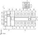
도 1은 본 실시형태에 따른 기판 처리 시스템의 개략 구성을 도시한 도면이다. 이하에서는, 위치 관계를 명확히 하기 위해서, 서로 직교하는 X축, Y축 및 Z축을 규정하고, Z축 정방향을 연직 상향 방향으로 한다.1 is a diagram showing a schematic configuration of a substrate processing system according to the present embodiment. In the following, in order to clarify the positional relationship, the X-axis, Y-axis, and Z-axis that are orthogonal to each other are defined, and the positive Z-axis direction is taken as the vertically upward direction.
도 1에 도시된 바와 같이, 기판 처리 시스템(1)은, 반입 반출 스테이션(2)과, 처리 스테이션(3)을 구비한다. 반입 반출 스테이션(2)과 처리 스테이션(3)은 인접하여 설치된다.As shown in FIG. 1 , the
반입 반출 스테이션(2)은, 캐리어 배치부(11)와, 반송부(12)를 구비한다. 캐리어 배치부(11)에는, 복수 매의 기판, 본 실시형태에서는 반도체 웨이퍼[이하 웨이퍼(W)]를 수평 상태로 수용하는 복수의 캐리어(C)가 배치된다.The carry-in/
반송부(12)는, 캐리어 배치부(11)에 인접하여 설치되고, 내부에 기판 반송 장치(13)와, 전달부(14)를 구비한다. 기판 반송 장치(13)는, 웨이퍼(W)를 유지하는 웨이퍼 유지 기구를 구비한다. 또한, 기판 반송 장치(13)는, 수평 방향 및 연직 방향으로의 이동 및 연직축을 중심으로 하는 선회가 가능하고, 웨이퍼 유지 기구를 이용하여 캐리어(C)와 전달부(14) 사이에서 웨이퍼(W)의 반송을 행한다.The
처리 스테이션(3)은, 반송부(12)에 인접하여 설치된다. 처리 스테이션(3)은, 반송부(15)와, 복수의 처리 유닛(16)을 구비한다. 복수의 처리 유닛(16)은, 반송부(15)의 양측에 나란히 설치된다.The
반송부(15)는, 내부에 기판 반송 장치(17)를 구비한다. 기판 반송 장치(17)는, 웨이퍼(W)를 유지하는 웨이퍼 유지 기구를 구비한다. 또한, 기판 반송 장치(17)는, 수평 방향 및 연직 방향으로의 이동 및 연직축을 중심으로 하는 선회가 가능하고, 웨이퍼 유지 기구를 이용하여 전달부(14)와 처리 유닛(16) 사이에서 웨이퍼(W)의 반송을 행한다.The
처리 유닛(16)은, 기판 반송 장치(17)에 의해 반송되는 웨이퍼(W)에 대해 소정의 기판 처리를 행한다.The
또한, 기판 처리 시스템(1)은, 제어 장치(4)를 구비한다. 제어 장치(4)는, 예컨대 컴퓨터이며, 제어부(18)와 기억부(19)를 구비한다. 기억부(19)에는, 기판 처리 시스템(1)에 있어서 실행되는 각종의 처리를 제어하는 프로그램이 저장된다. 제어부(18)는, 기억부(19)에 기억된 프로그램을 읽어내어 실행함으로써 기판 처리 시스템(1)의 동작을 제어한다.In addition, the
한편, 이러한 프로그램은, 컴퓨터에 의해 판독 가능한 기억 매체에 기록되어 있던 것이며, 그 기억 매체로부터 제어 장치(4)의 기억부(19)에 인스톨된 것이어도 좋다. 컴퓨터에 의해 판독 가능한 기억 매체로서는, 예컨대 하드 디스크(HD), 플렉시블 디스크(FD), 컴팩트 디스크(CD), 마그넷 옵티컬 디스크(MO), 메모리 카드 등이 있다.On the other hand, these programs may have been recorded in a computer-readable storage medium, and may have been installed into the
상기한 바와 같이 구성된 기판 처리 시스템(1)에서는, 먼저, 반입 반출 스테이션(2)의 기판 반송 장치(13)가, 캐리어 배치부(11)에 배치된 캐리어(C)로부터 웨이퍼(W)를 취출하고, 취출한 웨이퍼(W)를 전달부(14)에 배치한다. 전달부(14)에 배치된 웨이퍼(W)는, 처리 스테이션(3)의 기판 반송 장치(17)에 의해 전달부(14)로부터 취출되어, 처리 유닛(16)에 반입된다.In the
처리 유닛(16)에 반입된 웨이퍼(W)는, 처리 유닛(16)에 의해 처리된 후, 기판 반송 장치(17)에 의해 처리 유닛(16)으로부터 반출되어, 전달부(14)에 배치된다. 그리고, 전달부(14)에 배치된 처리가 완료된 웨이퍼(W)는, 기판 반송 장치(13)에 의해 캐리어 배치부(11)의 캐리어(C)로 복귀된다.After the wafer W carried into the
다음으로, 처리 유닛(16)에 대해 도 2를 참조하여 설명한다. 도 2는 처리 유닛의 개략 구성을 도시한 도면이다.Next, the
도 2에 도시된 바와 같이, 처리 유닛(16)은, 챔버(20)와, 기판 유지 기구(30)와, 처리 유체 공급부(40)와, 회수컵(50)을 구비한다.As shown in FIG. 2 , the
챔버(20)는, 기판 유지 기구(30)와 처리 유체 공급부(40)와 회수컵(50)을 수용한다. 챔버(20)의 천장부에는, FFU(Fan Filter Unit)(21)가 설치된다. FFU(21)는, 챔버(20) 내에 다운플로우를 형성한다.The
기판 유지 기구(30)는, 유지부(31)와, 지주부(32)와, 구동부(33)를 구비한다. 유지부(31)는, 웨이퍼(W)를 수평으로 유지한다. 지주부(32)는, 연직 방향으로 연장되는 부재이며, 기단부가 구동부(33)에 의해 회전 가능하게 지지되고, 선단부에 있어서 유지부(31)를 수평으로 지지한다. 구동부(33)는, 지주부(32)를 연직축 주위로 회전시킨다. 이러한 기판 유지 기구(30)는, 구동부(33)를 이용하여 지주부(32)를 회전시킴으로써 지주부(32)에 지지된 유지부(31)를 회전시키고, 이에 의해, 유지부(31)에 유지된 웨이퍼(W)를 회전시킨다.The
처리 유체 공급부(40)는, 웨이퍼(W)에 대해 처리 유체를 공급한다. 처리 유체 공급부(40)는, 처리 유체 공급원(70)에 접속된다.The processing
회수컵(50)은, 유지부(31)를 둘러싸도록 배치되고, 유지부(31)의 회전에 의해 웨이퍼(W)로부터 비산하는 처리액을 포집한다. 회수컵(50)의 바닥부에는, 배액구(排液口; 51)가 형성되어 있고, 회수컵(50)에 의해 포집된 처리액은, 이러한 배액구(51)로부터 처리 유닛(16)의 외부로 배출된다. 또한, 회수컵(50)의 바닥부에는, FFU(21)로부터 공급되는 기체를 처리 유닛(16)의 외부로 배출하는 배기구(52)가 형성된다.The
이하에 있어서, 지주부(32)의 회전축, 즉 웨이퍼(W)의 회전축을, 회전축(Ce)(도 3 참조)으로 하여 설명한다. 또한, 웨이퍼(W)의 직경 방향을, 직경 방향으로 하여 설명하는 경우가 있다.In the following, the rotational axis of the
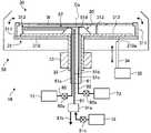
여기서, 처리 유닛(16)에 대해, 도 3을 참조하여 상세히 설명한다. 도 3은 처리 유닛(16)의 구체적인 구성을 도시한 도면이다. 한편, 도 3에서는, 처리 유체 공급부(40) 등, 일부의 구성을 생략하고 있다.Here, the
유지부(31)는, 유지 플레이트(310)와, 기판 유지부(311)와, 리프트 플레이트(312)와, 리프트 핀(313)을 구비한다.The holding
유지 플레이트(310)는, 원판형으로 형성되고, 지주부(32)의 상단이 삽입되는 구멍이 중심부에 형성된다. 유지 플레이트(310)는, 지주부(32)의 상단에 접합된다. 유지 플레이트(310)는, 지주부(32)와 동축 상에 배치된다. 유지 플레이트(310)의 외주단의 상면에는, 복수의 기판 유지부(311)가 설치된다. 예컨대, 기판 유지부(311)는, 3개소 설치되고, 각 기판 유지부(311)는, 둘레 방향으로 120°의 간격으로 설치된다. 기판 유지부(311)는, 리프트 플레이트(312)의 상하 이동에 맞춰 유지 플레이트(310)측의 기단부에 설치한 회동축을 중심으로 회동하여, 웨이퍼(W)의 유지 상태가 전환된다.The holding
또한, 유지 플레이트(310)에는, 승강 부재(34)가 삽입 가능한 복수의 삽입 구멍(310a)이 형성된다. 예컨대, 삽입 구멍(310a)은, 3개소 형성되고, 각 삽입 구멍(310a)은, 둘레 방향으로 120도의 간격으로 형성된다.In addition, a plurality of
승강 부재(34)는, 각 삽입 구멍(310a)에 따라 복수개 설치된다. 승강 부재(34)는, 승강 구동부(35)에 의해 승강한다. 승강 부재(34)는, 승강 구동부(35)에 의해 대기 위치로부터 상승되면 삽입 구멍(310a)에 삽입되고, 삽입 구멍(310a)을 관통하여 리프트 플레이트(312)에 접촉한다. 그리고, 승강 부재(34)는, 승강 구동부(35)에 의해 더욱 상승되면, 리프트 플레이트(312)를 상방으로 밀어 올린다. 승강 부재(34)는, 리프트 플레이트(312)를 소정의 상승 위치까지 밀어 올린다. 소정의 상승 위치는, 웨이퍼(W)를 기판 반송 장치(17)에 의해 반입 및 반송하는 위치이다. 승강 부재(34)는, 대기 위치에서는, 삽입 구멍(310a)에 삽입되지 않고, 유지 플레이트(310)는, 회전 가능해진다.A plurality of elevating
한편, 승강 부재(34)는, 유지 플레이트(310)에 설치된 중간 부재를 통해 리프트 플레이트(312)를 승강시켜도 좋다.On the other hand, the elevating
리프트 플레이트(312)는, 원판형으로 형성되고, 하면 처리부(80)의 축부(81)가 삽입되는 삽입 구멍이 중심부에 형성된다. 리프트 플레이트(312)는, 유지 플레이트(310), 즉 지주부(32)와 동축 상에 배치된다. 리프트 플레이트(312)는, 유지 플레이트(310)의 상방에 설치되고, 승강 부재(34)가 대기 위치에 있는 경우에는, 리프트 플레이트(312)의 하면은 유지 플레이트(310)의 상면에 접촉한다. 리프트 플레이트(312)의 외주단의 상면에는, 복수의 리프트 핀(313)이 설치된다. 예컨대, 리프트 핀(313)은, 3개소 설치되고, 각 리프트 핀(313)은, 둘레 방향으로 120도의 간격으로 설치된다. 리프트 플레이트(312)의 직경은 웨이퍼(W)의 직경보다 작고, 리프트 플레이트(312)는, 승강 부재(34)에 의해 밀어 올려진 경우에, 기판 유지부(311)에 접촉하지 않도록 형성된다.The
리프트 핀(313)은, 리프트 플레이트(312)가 밀어 올려지면, 웨이퍼(W)의 하면에 접촉하여, 웨이퍼(W)가 기판 유지부(311)에 의해 유지되지 않는 상태에서, 웨이퍼(W)를 하면측으로부터 지지한다. 또한, 웨이퍼(W)를 지지한 상태에서 리프트 플레이트(312)가 강하하고, 기판 유지부(311)에 의해 웨이퍼(W)가 유지된 후에, 더욱 리프트 플레이트(312)가 강하하면, 리프트 핀(313)은, 웨이퍼(W)의 하면으로부터 이격된다.When the
리프트 플레이트(312)의 하면이 유지 플레이트(310)의 상면에 접촉하는 상태에서는, 리프트 플레이트(312)와 유지 플레이트(310)는, 예컨대, 결합부에 의해 결합된다. 그 때문에, 구동부(33)에 의해 지주부(32)가 회전하면, 리프트 플레이트(312)와 유지 플레이트(310)는 지주부(32)와 함께 회전한다.In a state where the lower surface of the
처리 유닛(16)은, 웨이퍼(W)의 하면에 온도 조절액 등을 공급하는 하면 처리부(80)를 더 구비한다. 하면 처리부(80)는, 축부(81)와, 노즐(82)을 구비한다. 축부(81) 및 노즐(82)은, 내약품성을 갖는 수지, 예컨대, PCTFE(폴리클로로트리플루오로에틸렌) 수지에 의해 구성된다. 한편, 도 3에 있어서는, 설명을 위해서 하면 처리부(80)의 해칭을 생략하고 있다.The
축부(81)는, 지주부(32)와 동축 상에 배치된다. 축부(81)는, 중공형의 지주부(32) 및 리프트 플레이트(312)의 삽입 구멍에 삽입되고, 베어링(도시하지 않음)을 통해 지주부(32), 유지 플레이트(310) 및 리프트 플레이트(312)를 회전 가능하게 지지한다.The
축부(81)의 내부에는, 제1 유로(81a)와, 제2 유로(81b)와, 제3 유로(81c)가 형성된다. 각 유로(81a∼81c)는, 축 방향으로 연장되어 형성된다. 한편, 축부(81)를 중공형으로 형성하고, 각 유로가 되는 배관을, 축부(81) 내에 설치해도 좋다.Inside the
제1 유로(81a)에는, 온도 조절액 공급원(71)에 의해 온도 조절액, 예컨대 온도가 조정된 순수(純水)(온수)가 제1 배관(90)을 통해 공급된다. 한편, 제1 배관(90)에는, 개폐 밸브(90a)가 설치되어 있다.A temperature regulating liquid, for example, pure water (hot water) whose temperature is adjusted is supplied to the
제2 유로(81b)에는, DIW 공급원(72)에 의해 DIW(상온의 순수)가 제2 배관(91)을 통해 공급된다. 한편, 제2 배관(91)에는, 전환 밸브(91a)가 설치되어 있고, 전환 밸브(91a)를 전환하여 제2 유로(81b) 및 제2 배관(91)의 일부와 드레인 유로(91b)를 연통(連通)함으로써, 축부(81)의 상면에 부착된 약액 등을, 액 토출 유로(820a)(예컨대, 도 4 참조), 제2 유로(81b) 및 제2 배관(91)을 통해 배출 가능하게 되어 있다. 즉, 액 토출 유로(820a), 제2 유로(81b) 및 제2 배관(91)의 일부는 배출로로서도 기능한다. 한편, 전환 밸브(91a)와 DIW 공급원(72) 사이의 제2 배관(91)에는, 개폐 밸브(91c)가 설치되어 있다. 또한, 전환 밸브(91a)가 개폐 밸브(91c)의 기능을 가져도 좋다.DIW (pure water at normal temperature) is supplied to the
제3 유로(81c)에는, N2 공급원(73)에 의해 N2 가스가 제3 배관(92)을 통해 공급된다. N2 가스는, 고온(예컨대, 90℃ 정도)으로 온도 조절된다. 또한, 제3 유로(81c)는, 축부(81)의 상단에 형성되고, 상방으로 연장되어 설치되는 N2 노즐(81d) 내에도 형성된다. N2 노즐(81d)은, 노즐(82)의 베이스부(820)(예컨대, 도 4 참조)에 형성되는 삽입 구멍(820b)(예컨대, 도 4 참조)에 삽입된다. 한편, 제3 배관(92)에는, 개폐 밸브(92a)가 설치되어 있다.N2 gas is supplied to the
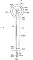
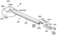
여기서, 노즐(82)에 대해, 도 4 내지 도 8을 참조하여 상세히 설명한다. 도 4는 노즐(82)의 평면도이다. 도 5는 도 4의 화살표 A방향에서 본 도면이다. 도 6은 노즐(82)의 사시도이다. 도 7은 노즐(82)의 분해도이다. 도 8은 도 6의 VIII-VIII 단면도이다.Here, the
노즐(82)은, 베이스부(820)와, 액 공급부(821)를 구비한다. 노즐(82)은, 리프트 플레이트(312)(도 3 참조)와 웨이퍼(W)(도 3 참조) 사이에 설치되고, 웨이퍼(W)의 하면과 마주 보도록 설치된다. 즉, 노즐(82)은, 웨이퍼(W)보다 하방에 설치된다. 또한, 노즐(82)은, 웨이퍼(W)의 하면과 약간 이격되도록 설치된다.The
베이스부(820)는, 축부(81)와 동축 상에 배치된다. 즉, 베이스부(820)는, 웨이퍼(W)의 회전축(Ce)을 포함하도록 설치된다. 베이스부(820)는, 축부(81)의 상단에 부착된다. 베이스부(820)에는, 제2 유로(81b)와 연통되는 액 토출 유로(820a)와, N2 노즐(81d)이 삽입되는 삽입 구멍(820b)이 형성된다. 액 토출 유로(820a) 및 삽입 구멍(820b)은, 축 방향을 따라 형성된다. 또한, 베이스부(820)에는, 제1 유로(81a)(도 3 참조)에 연통되고, 또한 액 공급부(821)의 노즐 베이스부(822)에 형성되는 제1 액 공급로(822a)에 연통되는 중간 유로(도시하지 않음)가 내부에 형성된다. 중간 유로는, 축 방향을 따라 형성된다.The
베이스부(820)는, 베어링(도시하지 않음)을 통해 리프트 플레이트(312)(도 3 참조)에 착좌(着座)하고 있고, 리프트 플레이트(312)를 회전 가능하게 지지하며, 리프트 플레이트(312)의 승강에 따라 승강한다. 즉, 노즐(82)[하면 처리부(80)]은, 리프트 플레이트(312)와 함께 승강한다.The
베이스부(820)의 상단 중앙부에는, 하방을 향해 움푹 들어간 오목부(820c)가 형성된다. 오목부(820c)에는, 액 토출 유로(820a) 및 삽입 구멍(820b)이 개구된다. 오목부(820c)는, 오목부(820c)에 부착된 액이 액 토출 유로(820a)에 유입되도록 형성된다. 즉, 오목부(820c)는, 액 토출 유로(820a)에 액이 유입되도록, 유발형으로 형성되고, 예컨대, 오목부(820c)를 형성하는 면이 액 토출 유로(820a)의 중심을 향해 수속(收束)되도록 형성된다.A
액 토출 유로(820a) 및 삽입 구멍(820b)은, 회전축(Ce) 부근에 형성된다. 즉, 삽입 구멍(820b) 및 삽입 구멍(820b)에 삽입되는 N2 노즐(81d)은, 회전축(Ce)으로부터 직경 방향 외측으로 오프셋된 위치에 설치된다. N2 노즐(81d)로부터 토출되는 N2 가스가, 웨이퍼(W)의 중심에 공급되면, N2 노즐(81d)의 직경보다 작은 액적이 웨이퍼(W)에 남을 우려가 있다. 이것을 억제하기 위해서, N2 노즐(81d)은, 회전축(Ce)으로부터 직경 방향 외측으로 오프셋된 위치에 설치된다.The
또한, 베이스부(820)의 상단 외주부에는, 오목부(820c)의 주연(周緣)으로부터 외주측 하방을 향해 경사지는 경사부(820e)가 형성된다. 즉, 경사부(820e)는, 직경 방향 외측이 됨에 따라 하방으로 경사진다. 경사부(820e)는, 베이스부(820)의 중심측으로부터 경사지도록 형성되는 것이 바람직하다. 즉, 오목부(820c)의 주연이 보다 직경 방향 내측에 위치하도록, 오목부(820c) 및 경사부(820e)가 형성되는 것이 바람직하다.Further, an
경사부(820e)는, 도 9에 도시된 바와 같이, 베이스부(820)의 하면(820f)에 접속된다. 즉, 경사부(820e)는, 오목부(820c)의 주연으로부터 베이스부(820)의 하면까지 연장되어 형성된다. 도 9는 도 3에 있어서의 하면 처리부(80)의 일부를 확대한 모식도이다.As shown in FIG. 9 , the
축부(81)와, 축부(81)가 삽입되는 지주부(32)의 삽입 구멍의 내주면 사이에는, 제1 간극(320)이 형성된다. 또한, 베이스부(820)의 하면(820f)과 리프트 플레이트(312) 사이에는, 제1 간극(320)과 연통되는 제2 간극(321)이 형성된다. 이러한 간극(320, 321)은, 회전하지 않는 축부(81) 및 노즐(82)과, 회전하는 지주부(32) 및 리프트 플레이트(312) 사이에 생긴다.A
웨이퍼(W), 지주부(32) 및 리프트 플레이트(312)가 회전하면, 제1 간극(320) 및 제2 간극(321)에서 부압을 발생하는 경우가 있어, 웨이퍼(W)의 중심측이 하측으로 휘어지는 경우가 있다. 이것을 방지하기 위해서, 제1 간극(320) 및 제2 간극(321)에는, 기체, 예컨대, N2 공급원(73)으로부터 N2 가스가 공급된다. 이에 의해, 부압이 발생하는 것을 방지하여, 웨이퍼(W)가 하측으로 휘어진 상태로 회전하는 것을 억제할 수 있어, 웨이퍼(W)와 노즐(82) 등의 접촉을 억제할 수 있다.When the wafer W, the
그러나, 제1 간극(320) 및 제2 간극(321)으로부터 토출된 N2 가스가 웨이퍼(W)의 하면에 닿으면, 웨이퍼(W)의 온도가 낮아져, 처리의 진행이 늦어지거나, 웨이퍼(W)에 있어서의 처리가 불균일해지거나 할 우려가 있다.However, when the N2 gas discharged from the
본 실시형태에서는, 경사부(820e)를 베이스부(820)의 하면(820f)까지 연장하여 형성함으로써, 베이스부(820)의 하면(820f)을 직경 방향 외측까지 연장하여 설치할 수 있고, N2 가스가 웨이퍼(W)를 향해 토출되는 것을 억제할 수 있다. 이에 의해, 처리의 진행이 늦어지거나, 웨이퍼(W)에 있어서의 처리가 불균일해지거나 하는 것을 억제할 수 있다.In this embodiment, by forming the
또한, 경사부(820e)는, 베이스부(820)의 강도를 확보하면서, 회전축(Ce)과의 이루는 각이 보다 예각이 되는 것이 바람직하다. 예컨대, 경사부(820e)는 회전축(Ce)과의 이루는 각이 45도 내지 50도 정도가 되도록 형성된다.In addition, it is preferable that the
이와 같이, 경사부(820e)를 형성함으로써, 베이스부(820)의 상면에 부착된 액을 베이스부(820)의 외측으로 흘려 보낼 수 있다.In this way, by forming the
한편, 베이스부(820)의 상단의 높이가, 후술하는 노즐 베이스부(822)의 상단의 높이보다 낮아지도록 베이스부(820)는 형성된다. 이에 의해, 베이스부(820)측의 노즐 베이스부(822)에 부착된 액을 베이스부(820)의 오목부(820c)나 경사부(820e)로 흘려 보낼 수 있다.Meanwhile, the
액 공급부(821)는, 막대형으로 형성되고, 베이스부(820)의 중심 부근으로부터 직경 방향 외측으로 연장되어 설치된다. 액 공급부(821)는, 노즐 베이스부(822)와, 노즐 캡(823)을 구비한다.The
직경 방향 내측의 노즐 베이스부(822)의 단부는, 오목부(820c) 내로 돌출되도록 형성된다. 한편, 직경 방향 내측의 노즐 베이스부(822)의 선단은, 회전축(Ce)보다 직경 방향 외측에 위치한다.An end of the
노즐 베이스부(822)의 내부에는, 제1 액 공급로(822a)와, 압입 구멍(822b)이 직경 방향을 따라 형성된다. 제1 액 공급로(822a)와 압입 구멍(822b)은 평행하게 형성된다. 직경 방향 내측의 압입 구멍(822b)의 단부는, 폐색되어 있다. 압입 구멍(822b)에는, 보강 부재(824)가 압입된다.Inside the
보강 부재(824)는, 중공형의 공동부를 갖는 금속 부재이고, 예컨대, 스테인리스강이다. 한편, 보강 부재(824)는, 스테인리스강에 한정되지 않고, 액 공급부(821)의 휘어짐을 억제하는 부재이면 된다. 보강 부재(824)를 중공형으로 함으로써, 보강 부재(824)를 압입 구멍(822b)에 압입할 때에, 공동부를 통해 압입 구멍(822b) 내의 공기가 외부로 배출되기 때문에, 보강 부재(824)를 압입 구멍(822b)에 용이하게 압입할 수 있다. 또한, 중공형으로 함으로써, 노즐(82)의 보온 효과를 향상시킬 수 있어, 제1 액 공급로(822a)를 흐르는 온도 조절액의 온도가 저하되는 것을 억제할 수 있다.The reinforcing
직경 방향 외측의 압입 구멍(822b)의 단부에는, 시일재(825)가 삽입된다. 또한, 직경 방향 외측의 압입 구멍(822b)에는 나사홈이 형성되어 있고, 나사(826)에 의해 노즐 캡(823)이 부착된다. 나사(826)는, 노즐(82)과 마찬가지로 내약품성의 수지에 의해 구성된다.A sealing
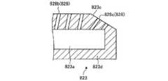
노즐 캡(823)은, 직경 방향 외측의 노즐 베이스부(822)의 선단에 부착된다. 노즐 캡(823)에는, 제1 액 공급로(822a)와 연통되는 제2 액 공급로(823a)가 형성되는 공급부(823d)와, 나사(826)가 삽입되는 나사 구멍이 형성되는 나사 부착부(823b)를 구비한다. 노즐 캡(823)은, 나사(826)에 의해 노즐 베이스부(822)에 부착된다.The
공급부(823d)는, 제2 액 공급로(823a)가, 노즐 캡(823)의 선단측, 즉 직경 방향 외측에서 폐색되도록 형성된다. 이와 같이, 제1 액 공급로(822a)와 제2 액 공급로(823a)에 의해 액 공급로가 형성된다. 또한, 공급부(823d)의 선단측의 상부에는, 하방으로 경사지는 테이퍼부(823c)가 형성된다.The
나사 부착부(823b)는, 웨이퍼(W)의 회전 시에, 나사(826)가 리프트 핀(313)(도 3 참조)에 접촉하지 않도록, 공급부(823d)의 선단보다 직경 방향 내측에 형성된다. 즉, 노즐 캡(823)은, 평면에서 보아 대략 L자형으로 형성된다.The
노즐 베이스부(822) 및 노즐 캡(823)에는, 상방으로 돌출되는 단차부(827)가 형성된다. 단차부(827)는, 예컨대, 평면에서 보아, 꼭대기부로부터 직경 방향과는 교차하는 방향으로 경사지는 경사면에 의해 형성된다. 단차부(827)에는, 액 공급로에 연통되고, 웨이퍼(W)의 하면을 향해 온도 조절액을 토출하는 토출구(828)가 복수개 형성된다. 토출구(828)를 단차부(827)에 형성함으로써, 예컨대, 액 토출 유로(820a)로부터 토출된 액이 토출구(828) 내에 유입되는 것을 억제할 수 있다.A stepped
토출구(828)는, 베이스부(820)의 중심측으로부터 노즐 캡(823)의 선단측, 즉 노즐 캡(823)의 테이퍼부(823c)까지 소정의 간격을 마련하여 형성된다. 또한, 토출구(828)는, 토출구(828)의 합계 면적이, 제1 유로(81a)의 단면적이나, 가장 직경 방향 내측의 제1 액 공급로(822a)의 단면적보다 작아지도록 형성된다. 이에 의해, 각 토출구(828)로부터 토출되는 온도 조절액의 유량을 균일하게 할 수 있다.The
토출구(828)는, 베이스부(820)의 중심측, 즉 회전축(Ce) 부근에 형성된 제1 토출구(828a)와, 제1 토출구(828a)보다 직경 방향 외측에 형성되는 제2 토출구(828b)와, 테이퍼부(823c)에 형성되는 제3 토출구(828c)에 의해 구성된다.The
제1 토출구(828a)는, 오목부(820c) 내로 돌출되는 노즐 베이스부(822)에 형성된다. 제1 토출구(828a)는, 상하 방향(연직 방향)에 있어서, 제1 액 공급로(822a)와 겹쳐지도록 형성된다. 또한, 제1 토출구(828a)는, 축 방향을 따라 온도 조절액을 토출하도록 형성된다. 이에 의해, 웨이퍼(W)의 중심 부근의 하면에 온도 조절액을 토출할 수 있다.The
한편, 가장 회전축(Ce)측의 제1 토출구(828a)는, 회전축(Ce)보다 직경 방향 외측에 형성된다. 가장 회전축(Ce)측의 제1 토출구(828a)를 회전축(Ce)보다 직경 방향 외측에 형성함으로써, 원심력이 작용하지 않는 웨이퍼(W)의 중심부가, 제1 토출구(828a)로부터 토출된 온도 조절액에 의해 온도가 높아지는 것을 억제하여, 웨이퍼(W)의 중심부의 처리가 다른 영역보다 진행되는 것을 억제하여, 에칭 처리를 균일하게 행할 수 있다.On the other hand, the
제2 토출구(828b)는, 도 10에 도시된 바와 같이, 상하 방향에 있어서, 제1 액 공급로(822a) 및 제2 액 공급로(823a)와 겹쳐지지 않도록, 제1 액 공급로(822a) 및 제2 액 공급로(823a)에 대해 웨이퍼(W)의 회전 방향의 하류측으로 오프셋되어 형성된다. 제2 토출구(828b)는, 웨이퍼(W)의 회전 방향에 있어서 노즐(82)보다 후방측의 비스듬히 상방을 향해 온도 조절액을 토출한다. 도 10은 제2 토출구(828b)로부터 토출되는 온도 조절액의 토출 방향을 측면에서 보아 도시한 개략도이다. 이에 의해, 웨이퍼(W)에 닿은 온도 조절액이 노즐(82)을 향해 떨어지는 것을 억제하여, 노즐(82)에 온도 조절액이 부착되는 것을 억제할 수 있다.As shown in FIG. 10 , the
또한, 제2 토출구(828b)는, 도 11에 도시된 바와 같이, 평면에서 보아 노즐(82)에 대해 수직인 방향(도 11 중, 파선 화살표)보다 외측(도 11 중, 실선 화살표)을 향해 온도 조절액을 토출하도록 형성된다. 즉, 제2 토출구(828b)는, 온도 조절액을 외측 비스듬히 상방을 향해 토출하도록 형성된다. 도 11은 제2 토출구(828b)로부터 토출되는 온도 조절액의 토출 방향 및 웨이퍼(W)의 하면에 있어서의 온도 조절액의 토출 범위를 도시한 개략도이다. 온도 조절액을 외측 비스듬히 상방을 향해 토출함으로써, 노즐(82)에 대해 수직인 방향을 향해 토출하는 경우(도 11 중, 파선 범위)보다 토출 거리가 길어지기 때문에, 웨이퍼(W)의 하면의 광범위(도 11 중, 실선 범위)에 온도 조절액을 토출할 수 있다. 한편, 도 4 내지 도 7에서는, 일부의 제2 토출구(828b)를 생략하고 있다.In addition, as shown in FIG. 11 , the
제3 토출구(828c)는, 기본적인 구성은, 제2 토출구(828b)와 동일하고, 제2 토출구(828b)보다 온도 조절액을 직경 방향 외측을 향해 토출하도록 형성된다. 이에 의해, 액 공급부(821)를 연장시킬 수 없는 웨이퍼(W)의 외주단측의 하면에 온도 조절액을 토출할 수 있다. 예컨대, 리프트 핀(313)의 상방에 위치하는 웨이퍼(W)의 하면이나, 리프트 핀(313)보다 직경 방향 외측에 위치하는 웨이퍼(W)의 하면에 온도 조절액을 토출할 수 있다. 이에 의해, 웨이퍼(W)의 외주단측의 온도가 저하되는 것을 억제할 수 있다.The
한편, 제3 토출구(828c)는, 온도 조절액을, 웨이퍼(W)의 회전 방향에 있어서 노즐(82)보다 후방측에 토출하지 않고, 직경 방향 외측의 비스듬히 상방을 향해 토출하도록 형성되어도 좋다.On the other hand, the
노즐 캡(823)의 선단측의 제2 토출구(828b)의 간격, 및 제3 토출구(828c)의 간격은, 베이스부(820)측의 제2 토출구(828b)의 간격보다 짧다. 예컨대, 베이스부(820)측의 제2 토출구(828b)의 간격은, 10 ㎜이고, 제3 토출구(828c) 및 테이퍼부(823c) 근방의 제2 토출구(828b)의 간격은, 8 ㎜이다.The interval between the
이와 같이, 노즐 캡(823)의 선단측에 형성한 제2 토출구(828b) 및 제3 토출구(828c)의 간격을 짧게 함으로써, 웨이퍼(W)의 주연측의 하면에 토출되는 면적당의 공급량을 많게 할 수 있다.In this way, by shortening the interval between the
또한, 제2 토출구(828b)는, 직경 방향 외측이 됨에 따라 제2 토출구(828b)의 간격이 작아지도록 형성해도 좋다.Further, the
한편, 도 4 내지 도 7에서는, 제1 토출구(828a) 및 제3 토출구(828c)를 2개 형성한 일례를 도시하고 있으나, 이것에 한정되는 일은 없고, 하나 이상이면 된다.Meanwhile, in FIGS. 4 to 7 , an example in which two
노즐(82)의 외주단, 즉 노즐 캡(823)의 외주단은, 리프트 핀(313)보다 직경 방향 내측에 위치한다. 그 때문에, 리프트 플레이트(312)가 유지 플레이트(310)와 함께 회전한 경우라도, 노즐(82)과 리프트 핀(313)이 접촉하는 일은 없다.The outer circumferential end of the
다음으로, 본 실시형태에 따른 기판 처리 시스템(1)이 실행하는 기판 처리의 내용에 대해 도 12를 참조하여 설명한다. 도 12는 본 실시형태에 따른 기판 처리 시스템(1)이 실행하는 처리의 처리 순서를 도시한 흐름도이다. 한편, 도 12에 도시된 각 처리 순서는, 제어 장치(4)의 제어부(18)의 제어에 따라 실행된다.Next, the content of substrate processing executed by the
기판 반송 장치(17)에 의해 처리 유닛(16)에 웨이퍼(W)를 반입하는 반입 처리가 행해진다(S1). 반입 처리에서는, 소정의 상승 위치까지 리프트 플레이트(312)가 밀어 올려지고, 기판 반송 장치(17)에 의해 리프트 핀(313) 상에 웨이퍼(W)가 배치된다. 그리고, 리프트 핀(313) 상에 배치된 후에, 리프트 플레이트(312)가 강하하고, 기판 유지부(311)에 의해 웨이퍼(W)가 유지된다. 이 상태에서는, 노즐(82) 및 리프트 핀(313)과, 웨이퍼(W)의 하면은 약간 이격되어 있다.A carrying process of carrying the wafer W into the
처리 유닛(16)에서는, 약액 처리가 행해진다(S2). 약액 처리에서는, 구동부(33)에 의해 유지부(31)가 회전되어, 웨이퍼(W)가 회전한다. 그리고, 처리 유체 공급부(40)의 에칭액 공급용 노즐(도시하지 않음)로부터 에칭액, 예컨대, SC1이나, DHF나, SPM이 웨이퍼(W)의 상면에 공급되고, 또한, 하면 처리부(80)의 노즐(82)로부터 온도 조절액이 웨이퍼(W)의 하면에 공급된다. 이에 의해, 웨이퍼(W)의 상면에 에칭 처리가 행해진다.In the
그때, 토출구(828)로부터 웨이퍼(W)의 하면에 온도 조절액이 공급됨으로써, 웨이퍼(W)의 온도를 균일하게 할 수 있어, 웨이퍼(W)에 대해, 에칭 처리를 균일하게 행할 수 있다.At this time, by supplying the temperature control liquid to the lower surface of the wafer W from the
또한, 에칭액 공급용 노즐은, 웨이퍼(W)의 중심으로부터 외주단까지 왕복 이동하면서 에칭액을 웨이퍼(W)의 상면에 공급한다. 한편, 웨이퍼(W)의 외주단에 에칭액을 공급하는 노즐(82)을 별도로 설치해도 좋다. 이에 의해, 웨이퍼(W)에 대해, 에칭 처리를 균일하게 행할 수 있다.In addition, the nozzle for supplying the etchant supplies the etchant to the upper surface of the wafer W while reciprocating from the center to the outer peripheral edge of the wafer W. On the other hand, a
처리 유닛(16)에서는, 약액 처리 후에 린스 처리가 행해진다(S3). 린스 처리에서는, 처리 유체 공급부(40)의 린스액 공급용 노즐(도시하지 않음)로부터 DIW가 웨이퍼(W)의 상면에 공급된다. 또한, 하면 처리부(80)의 액 토출 유로(820a)로부터 DIW가 웨이퍼(W)의 하면에 공급된다. 이에 의해, 웨이퍼(W)에 잔존하는 에칭액이 DIW에 의해 씻겨진다.In the
계속해서, 처리 유닛(16)에서는, 건조 처리가 행해진다(S4). 건조 처리에서는, 처리 유체 공급부(40)의 건조액 공급용 노즐(도시하지 않음)로부터 IPA가 웨이퍼(W)의 상면에 공급된다. 또한, 하면 처리부(80)의 N2 노즐(81d)로부터 N2 가스가 웨이퍼(W)의 하면에 공급된다. N2 가스가 웨이퍼(W)의 하면에 공급됨으로써, 건조 처리가 촉진된다.Then, in the
웨이퍼(W)가 회전하고 있는 경우에, 웨이퍼(W)의 중심부는, 웨이퍼(W)의 주연부보다 원심력이 작다. 그 때문에, 웨이퍼(W)의 중심부 아래에 위치하는 베이스부(820)의 상단 중앙부에는 액이 낙하하기 쉬워, 액이 부착되기 쉽다.When the wafer W is rotating, the centrifugal force at the center of the wafer W is smaller than that at the periphery of the wafer W. Therefore, the liquid tends to fall and adhere to the upper end center portion of the
상기 실시형태에서는, 베이스부(820)의 상단 중앙부에 부착된 액이 액 토출 유로(820a)에 유입되도록 오목부(820c)가 형성되어 있다. 그 때문에, 오목부(820c)에 잔존하는 액이 적어, 건조 처리 시에, 오목부(820c)에 잔존한 액이 웨이퍼(W)의 하면에 부착되는 것을 억제할 수 있다.In the above embodiment, the
또한, 건조 처리에서는, 전환 밸브(91a)가 전환되어, 액 토출 유로(820a), 제2 유로(81b) 및 제2 배관(91)의 일부와, 드레인 유로(91b)가 연통된다. 이에 의해, 액 토출 유로(820a)에 유입된 액이 드레인 유로(91b)를 통해 배출되기 때문에, 웨이퍼(W)의 하면에 액이 부착되는 것을 억제할 수 있다. 또한, 액 토출 유로(820a)와 드레인 유로(91b)가 연통됨으로써 액 토출 유로(820a)의 개구 부근이 부압이 되기 때문에, 오목부(820c)에 잔존한 액이 액 토출 유로(820a)에 흡인되어 배출된다. 이에 의해, 오목부(820c)에 잔존한 액이 웨이퍼(W)의 하면에 부착되는 것을 더욱 억제할 수 있다.In the drying process, the
한편, 린스 처리 및 건조 처리에서는, 웨이퍼(W)는 기판 유지부(311)에 의해 유지되어, 회전하고 있다.On the other hand, in the rinsing process and the drying process, the wafer W is held and rotated by the
다음으로, 처리 유닛(16)에서는, 반출 처리가 행해진다(S5). 반출 처리에서는, 웨이퍼(W)의 회전이 정지된 후에, 승강 부재(34)에 의해 리프트 플레이트(312)가 소정의 상승 위치까지 밀어 올려진다. 그리고, 기판 반송 장치(17)에 의해 웨이퍼(W)가 처리 유닛(16)으로부터 반출된다.Next, in the
다음으로 본 실시형태의 효과에 대해 설명한다.Next, the effect of this embodiment is demonstrated.
베이스부(820)의 상면에 개구되는 액 토출 유로(820a)를 배출로로서 기능시키고, 베이스부(820)의 상단 중앙부에 액 토출 유로(820a)를 향해 액이 흐르도록 하방으로 움푹 들어간 오목부(820c)를 형성함으로써, 오목부(820c)에 잔존한 액을 액 토출 유로(820a)로 흘려 보낼 수 있다.A concave portion recessed downward so that the
이에 의해, 오목부(820c)에 액이 남는 것을 억제하여, 오목부(820c)에 잔존한 액이 웨이퍼(W)의 하면에 부착되는 것을 억제할 수 있다.Accordingly, it is possible to suppress the liquid remaining in the
오목부(820c)의 주연으로부터 베이스부(820)의 외측이 됨에 따라 하방으로 경사지는 경사부(820e)를 형성하여, 베이스부(820)의 상면에 부착된 액을 베이스부(820)의 외측으로 배출함으로써, 베이스부(820)의 상면에 잔존하는 액을 적게 하여, 액이 웨이퍼(W)의 하면에 부착되는 것을 억제할 수 있다.An
또한, 오목부(820c)의 주연으로부터 경사부(820e)를 형성함으로써, 수평한 면이 베이스부(820)의 상면에 형성되지 않는다. 그 때문에, 베이스부(820)의 상면에 잔존하는 액을 적게 하여, 액이 웨이퍼(W)의 하면에 부착되는 것을 억제할 수 있다.Further, by forming the
축부(81)와 지주부(32) 사이에 형성되는 제1 간극(320)과, 리프트 플레이트(312)와 베이스부(820)의 하면(820f) 사이에 형성되는 제2 간극(321)에 N2 가스 등을 공급하고, 경사부(820e)를 베이스부(820)의 하면(820f)까지 연장하여 형성한다.N in the
이에 의해, 웨이퍼(W)를 회전시키는 경우에, 제1 간극(320) 및 제2 간극(321)에서 부압이 발생하는 것을 방지하여, 웨이퍼(W)가 휘어진 상태로 회전하는 것을 억제함으로써, 웨이퍼(W)와 노즐(82) 등의 접촉을 억제할 수 있다. 또한, 제2 간극(321)으로부터 토출된 N2 가스가 웨이퍼(W)를 향해 토출되는 것을 억제할 수 있어, 웨이퍼(W)가 냉각되는 것을 억제할 수 있다. 그 때문에, 처리의 진행이 늦어지거나, 웨이퍼(W)에 있어서의 처리가 불균일해지거나 하는 것을 억제할 수 있다.Accordingly, when the wafer W is rotated, generation of negative pressure in the
상하 방향에 있어서 제1 액 공급로(822a)와 겹쳐지도록 제1 토출구(828a)가 형성된다. 또한, 제1 토출구(828a)보다 직경 방향 외측이고, 상하 방향에 있어서 제1 액 공급로(822a) 및 제2 액 공급로(823a)와 겹쳐지지 않도록, 제1 액 공급로(822a) 및 제2 액 공급로(823a)에 대해 웨이퍼(W)의 회전 방향의 하류측으로 오프셋된 제2 토출구(828b)가 형성된다.The
이에 의해 제1 토출구(828a)에 의해 웨이퍼(W)의 중심측의 하면에 온도 조절액을 토출할 수 있다. 또한, 제2 토출구(828b)로부터 토출된 온도 조절액이 노즐(82)에 부착되는 것을 억제할 수 있다.Accordingly, the temperature control liquid can be discharged to the lower surface of the center side of the wafer W through the
노즐(82)에 상방으로 돌출되는 단차부(827)를 형성하고, 단차부(827)에 토출구(828)가 형성된다. 이에 의해, 노즐(82)의 상면에 액이 남는 것을 억제할 수 있다.A stepped
또한, 베이스부(820)의 상단의 높이를, 노즐 베이스부(822)의 상단의 높이보다 낮게 한다. 이에 의해, 베이스부(820)측의 노즐 베이스부(822)에 부착된 액을 베이스부(820)의 오목부(820c)나 경사부(820e)로 흘려 보낼 수 있다.Moreover, the height of the upper end of the
액 공급부(821)의 선단측의 상부에 테이퍼부(823c)를 형성하고, 테이퍼부(823c)에 제3 토출구(828c)가 형성된다. 이에 의해, 테이퍼부(823c)가 형성되지 않는 경우와 비교하여, 보다 웨이퍼(W)의 외주측으로 온도 조절액을 도달하게 할 수 있어, 액 공급부(821)의 선단측에 온도 조절액이 남기 어렵다. 또한, 제3 토출구(828c)의 가공이 용이해진다.A tapered
또한, 제3 토출구(828c)는, 직경 방향 외측을 향해 온도 조절액을 토출하도록 형성된다. 이에 의해, 웨이퍼(W)의 외주단의 하방에 리프트 핀(313)이 설치되어 있는 경우에도, 웨이퍼(W)의 외주단의 하면에 온도 조절액을 토출할 수 있어, 웨이퍼(W)의 외주측의 온도가 낮아지는 것을 억제하여, 웨이퍼(W)에 대해, 에칭 처리를 균일하게 행할 수 있다.Further, the
직경 방향 내측의 노즐 베이스부(822)의 단부는, 오목부(820c) 내로 돌출되도록 형성되고, 오목부(820c) 내로 돌출되는 노즐 베이스부(822)에 제1 토출구(828a)가 형성된다. 이에 의해, 제1 토출구(828a)로부터 토출되어, 웨이퍼(W)에 닿아 떨어진 온도 조절액을 오목부(820c)를 통해 액 토출 유로(820a)로 흘려 보낼 수 있다.An end of the
또한, 가장 회전축(Ce)측의 제1 토출구(828a)는, 회전축(Ce)보다 직경 방향 외측에 형성된다. 이에 의해, 회전축(Ce)의 하면에 온도 조절액이 토출되는 것을 억제하여, 원심력이 작용하지 않는 웨이퍼(W)의 중심부의 처리가 다른 영역보다 진행되는 것을 억제하여, 웨이퍼(W)에 대해, 에칭 처리를 균일하게 행할 수 있다.Further, the
토출구(828)는, 토출구(828)의 합계 면적이, 제1 유로(81a)나, 가장 직경 방향 내측의 제1 액 공급로(822a)의 단면적보다 작아지도록 형성된다. 이에 의해, 각 토출구(828)로부터 토출되는 온도 조절액의 유량을 균일하게 할 수 있다.The
액 공급부(821)는, 노즐 베이스부(822)와, 직경 방향 외측의 노즐 베이스부(822)의 선단에 부착되는 노즐 캡(823)에 의해 구성된다. 이에 의해, 간이한 구성으로 액 공급부(821)를 형성할 수 있다.The
노즐 캡(823)은, 제2 액 공급로(823a)가 형성되는 공급부(823d)와, 공급부(823d)의 선단보다 직경 방향 내측에 형성되고, 나사(826)에 의해 노즐 캡(823)을 노즐 베이스부(822)에 부착하는 나사 부착부(823b)를 구비한다. 이에 의해, 웨이퍼(W)가 회전한 경우에, 나사(826)가 리프트 핀(313)에 접촉하는 것을 방지할 수 있다.The
제1 액 공급로(822a)에 대해 평행하게 보강 부재(824)를 설치함으로써, 액 공급부(821)가 휘어지는 것을 억제하여, 액 공급부(821)와 다른 부재, 예컨대, 웨이퍼(W)나 리프트 플레이트(312)에 접촉하는 것을 방지할 수 있다.By providing the reinforcing
보강 부재(824)에 중공형의 공동부를 형성함으로써, 노즐(82)의 보온 효과를 향상시킬 수 있어, 온도 조절액의 온도가 낮아지는 것을 억제할 수 있다.By forming a hollow cavity in the reinforcing
다음으로 본 실시형태의 변형예에 대해 설명한다.Next, a modified example of this embodiment will be described.
상기 실시형태에서는, 노즐(82)로부터 온도 조절액인 순수를 토출하였으나, 에칭액을 토출해도 좋다. 또한, 액 토출 유로(820a)로부터 웨이퍼(W)의 하면에 DIW를 공급하였으나, SC1 등의 약액을 공급해도 좋다.In the above embodiment, pure water as a temperature control liquid is discharged from the
또한, 상기 실시형태에서는, 약액 처리를 1회 행하는 경우에 대해 설명하였으나, 약액 처리를 복수 회 행해도 좋다. 또한, 전환 밸브(91a)를 전환하여 액 토출 유로(820a)와 드레인 유로(91b)가 연통되는 타이밍은, 건조 처리 시에 한정되지 않고, 다른 처리 시에, 또는 각 처리 사이여도 좋다. 이에 의해, 웨이퍼(W)의 하면에 액이 부착되는 것을 억제할 수 있다.In the above embodiment, the case where the chemical treatment is performed once has been described, but the chemical treatment may be performed a plurality of times. In addition, the timing at which the switching
또한, 상기 실시형태에서는, 보강 부재(824)는 공동부를 갖고 있으나, 공동부를 갖지 않는, 예컨대 원기둥형으로 해도 좋다. 또한, 보강 부재(824)를 압입 구멍(822b)에 압입하였으나, 노즐 베이스부(822)에 형성한 구멍에, 예컨대, 원기둥형의 보강 부재(824)를 삽입해도 좋다. 한편, 구멍에 삽입하는 경우에는 보강 부재(824)와 구멍과의 간극이 작아지도록 보강 부재(824) 및 구멍이 조정된다. 이러한 구성에 의해서도, 액 공급부(821)의 휘어짐을 억제할 수 있다.Further, in the above embodiment, the reinforcing
또한, 오목부(820c)에 부착된 액을 배출하는 배출구, 배출로를, 베이스부(820)나 축부(81) 등에 별도로 형성해도 좋다.Further, a discharge port and a discharge path for discharging the liquid adhering to the
또한, 노즐(82)의 표면을 소수성으로 해도 좋다. 이에 의해, 오목부(820c)나 경사부(820e)나, 단차부(827)에 액이 남는 것을 억제할 수 있다.Also, the surface of the
한층 더한 효과나 변형예는, 당업자에 의해 용이하게 도출될 수 있다. 이 때문에, 본 발명의 보다 광범위한 양태는, 이상과 같이 나타내고 또한 기술한 특정한 상세 및 대표적인 실시형태에 한정되는 것이 아니다. 따라서, 첨부의 특허청구의 범위 및 그 균등물에 의해 정의되는 총괄적인 발명의 개념의 정신 또는 범위에서 일탈하지 않고, 여러 가지 변경이 가능하다.Further effects and modified examples can be easily derived by those skilled in the art. For this reason, the broader aspect of this invention is not limited to the specific detailed and representative embodiment shown and described above. Therefore, various changes are possible, without deviating from the mind or range of the concept of a comprehensive invention defined by the appended claims and their equivalents.
1: 기판 처리 시스템(액처리 장치)16: 처리 유닛
18: 제어부30: 기판 유지 기구
31: 유지부32: 지주부
33: 구동부73: N2 공급원(기체 공급부)
80: 하면 처리부81: 축부
81b: 제2 유로(배출로)82: 노즐
91: 제2 배관(배출로)310: 유지 플레이트
311: 기판 유지부312: 리프트 플레이트(판부)
313: 리프트 핀820: 베이스부
820a: 액 토출 유로(배출로)820c: 오목부
820e: 경사부821: 액 공급부
822: 노즐 베이스부(제1 공급부)822a: 제1 액 공급로(액 공급 유로)
822b: 압입 구멍823: 노즐 캡(제2 공급부)
823a: 제2 액 공급로(액 공급 유로)823b: 나사 부착부(부착부)
823c: 테이퍼부823d: 공급부
824: 보강 부재826: 나사(고정부)
828: 토출구828a: 제1 토출구
828b: 제2 토출구828c: 제3 토출구1: substrate processing system (liquid processing device) 16: processing unit
18: control unit 30: substrate holding mechanism
31: holding part 32: holding part
33: drive unit 73: N2 supply source (gas supply unit)
80: lower surface processing unit 81: shaft unit
81b: second passage (discharge passage) 82: nozzle
91: second piping (discharge path) 310: retaining plate
311: board holding part 312: lift plate (plate part)
313: lift pin 820: base part
820a: liquid discharge flow path (discharge path) 820c: concave portion
820e: inclined part 821: liquid supply part
822: nozzle base part (first supply part) 822a: first liquid supply path (liquid supply passage)
822b Press-in
823a: Second liquid supply path (liquid supply passage) 823b: Screw attachment part (attachment part)
823c: tapered
824: reinforcing member 826: screw (fixing part)
828:
828b:
Claims (14)
Translated fromKorean상기 기판 유지부를 회전시키는 구동부와,
상기 기판 유지부에 유지된 상기 기판의 회전축을 포함하고, 상기 회전축의 축 방향을 따라 연장되어 설치되며, 또한 상기 기판보다 하방에 설치된 축부와,
상기 축부의 상단부에 부착되는 베이스부와, 상기 베이스부로부터 상기 기판의 직경 방향 외측으로 연장되어 설치되고, 상기 기판을 향해 액을 토출하는 토출구가 형성된 액 공급부를 포함하고, 상기 기판의 하면을 향해 액을 토출하는 노즐과,
삽입 구멍에 삽입된 상기 축부에 의해 회전 가능하게 지지되어 상기 기판 유지부와 함께 회전하는 지주부와,
상기 베이스부의 하면 및 상기 기판의 하면과 마주 보고, 상기 기판 유지부와 일체로 회전하는 판부와,
상기 삽입 구멍을 형성하는 내주면과 상기 축부 사이에 형성되는 제1 간극을 통해, 상기 베이스부의 하면과 상기 판부 사이에 형성되고, 상기 제1 간극에 연통(連通)되는 제2 간극에 기체를 공급하는 기체 공급부
를 포함하고,
상기 축부 및 상기 베이스부는,
상기 축 방향을 따라 형성되고, 상기 기판의 하면을 향해 토출된 상기 액을 배출하는 배출로를 포함하며,
상기 베이스부는,
상기 액이 상기 배출로를 향해 흐르도록 하방을 향해 움푹 들어간 오목부와,
상기 오목부의 주연(周緣)으로부터 상기 베이스부의 외측이 됨에 따라 하방으로 경사지는 경사부를 포함하고,
상기 경사부는, 상기 베이스부의 하면까지 연장되어 형성되는 것인 액처리 장치.a substrate holder for holding the substrate horizontally;
a driving unit for rotating the substrate holding unit;
a shaft portion including a rotation shaft of the substrate held by the substrate holding unit, extending along an axial direction of the rotation shaft, and installed below the substrate;
A base portion attached to an upper end of the shaft portion, and a liquid supply portion extending from the base portion in a radial direction outside the substrate and having a discharge port for discharging liquid toward the substrate; A nozzle for discharging a liquid;
a support portion rotatably supported by the shaft portion inserted into the insertion hole and rotating together with the substrate holding portion;
a plate portion facing the lower surface of the base portion and the lower surface of the substrate and integrally rotating with the substrate holding portion;
Through a first gap formed between the inner circumferential surface forming the insertion hole and the shaft part, gas is supplied to a second gap formed between the lower surface of the base part and the plate part and communicating with the first gap. gas supply
including,
The shaft portion and the base portion,
A discharge path formed along the axial direction and discharging the liquid discharged toward the lower surface of the substrate;
the base part,
a concave portion recessed downward so that the liquid flows toward the discharge path;
Including an inclined portion that inclines downward from the periphery of the concave portion to the outside of the base portion,
The inclined portion is formed to extend to the lower surface of the base portion.
상기 기판 유지부를 회전시키는 구동부와,
상기 기판 유지부에 유지된 상기 기판의 회전축을 포함하고, 상기 회전축의 축 방향을 따라 연장되어 설치되며, 또한 상기 기판보다 하방에 설치된 축부와,
상기 기판의 하면을 향해 액을 토출하는 노즐
을 포함하고,
상기 노즐은,
상기 축부의 상단부에 부착되는 베이스부와, 상기 베이스부로부터 상기 기판의 직경 방향 외측으로 연장되어 설치되고, 상기 기판을 향해 액을 토출하는 토출구가 형성된 액 공급부를 포함하고,
상기 축부 및 상기 베이스부는,
상기 축 방향을 따라 형성되고, 상기 기판의 하면을 향해 토출된 상기 액을 배출하는 배출로를 포함하며,
상기 베이스부는,
상기 액이 상기 배출로를 향해 흐르도록 하방을 향해 움푹 들어간 오목부를 포함하고,
상기 액 공급부는,
상기 기판의 직경 방향을 따라 형성되고, 상기 토출구와 연통되는 액 공급 유로를 포함하고,
상기 토출구는,
상기 베이스부측에 형성되고, 상하 방향에 있어서 상기 액 공급 유로와 겹쳐지도록 형성된 1개 이상의 제1 토출구와,
상기 제1 토출구보다 상기 직경 방향 외측에 복수개 형성되고, 상기 상하 방향에 있어서 상기 액 공급 유로와 겹쳐지지 않도록, 상기 액 공급 유로에 대해 상기 기판의 회전 방향의 하류측으로 오프셋되어 형성되는 1개 이상의 제2 토출구를 포함하고,
상기 회전축측의 상기 액 공급부는, 상기 오목부 내로 돌출되고,
상기 제1 토출구는, 상기 오목부 내의 상기 액 공급부에 형성되는 것인 액처리 장치.a substrate holder for holding the substrate horizontally;
a driving unit for rotating the substrate holding unit;
a shaft portion including a rotation shaft of the substrate held by the substrate holding unit, extending along an axial direction of the rotation shaft, and installed below the substrate;
A nozzle for discharging liquid toward the lower surface of the substrate
including,
The nozzle is
A base portion attached to an upper end of the shaft portion, and a liquid supply portion extending from the base portion in a radial direction outside the substrate and having a discharge port for discharging liquid toward the substrate;
The shaft portion and the base portion,
A discharge passage formed along the axial direction and discharging the liquid discharged toward the lower surface of the substrate;
the base part,
A concave portion recessed downward so that the liquid flows toward the discharge passage;
The liquid supply unit,
A liquid supply passage formed along the radial direction of the substrate and communicating with the discharge port;
The outlet is
one or more first discharge ports formed on the side of the base portion and overlapping the liquid supply passage in the vertical direction;
One or more first discharge ports are formed in plural numbers outside the first discharge port in the radial direction, and formed offset from the liquid supply passage in a downstream direction in the rotational direction of the substrate so as not to overlap with the liquid supply passage in the vertical direction. 2 includes a discharge port;
The liquid supply part on the side of the rotating shaft protrudes into the concave part,
The liquid processing device, wherein the first discharge port is formed in the liquid supply part in the concave part.
상기 액 공급부의 선단측의 상부에 형성된 테이퍼부
를 더 포함하고,
상기 토출구는, 상기 테이퍼부에 형성된 1개 이상의 제3 토출구를 포함하는 것인 액처리 장치.The method of claim 2 or 3, wherein the liquid supply unit,
A tapered portion formed on the upper side of the tip side of the liquid supply unit
Including more,
The liquid processing device, wherein the discharge port includes one or more third discharge ports formed in the tapered portion.
상기 베이스부로부터 상기 직경 방향을 따라 연장되어 설치되는 제1 액 공급부와,
상기 직경 방향 외측의 상기 제1 액 공급부의 단부에 부착되고, 상기 직경 방향을 따라 연장되어 설치되는 제2 액 공급부를 포함하는 것인 액처리 장치.The method of claim 2 or 3, wherein the liquid supply unit,
A first liquid supply part extending from the base part along the radial direction;
and a second liquid supply unit attached to an end of the first liquid supply unit outside the radial direction and extending along the radial direction.
상기 액 공급 유로 및 상기 토출구가 형성되는 공급부와,
상기 직경 방향 외측의 상기 공급부의 선단보다 상기 축부측에 설치되고, 고정부에 의해 상기 제1 액 공급부에 부착되는 부착부
를 포함하는 것인 액처리 장치.The method of claim 6, wherein the second liquid supply unit,
a supply unit in which the liquid supply passage and the discharge port are formed;
An attachment portion provided on the shaft portion side of the tip of the supply portion outside in the radial direction and attached to the first liquid supply portion by a fixing portion.
A liquid treatment device comprising a.
상기 액 공급 유로에 대해 평행하게 형성된 구멍과,
상기 구멍에 삽입되는 보강 부재
를 포함하는 것인 액처리 장치.The method of claim 6, wherein the first liquid supply unit,
A hole formed parallel to the liquid supply passage;
A reinforcing member inserted into the hole
A liquid treatment device comprising a.
Applications Claiming Priority (2)
| Application Number | Priority Date | Filing Date | Title |
|---|---|---|---|
| JP2017022350AJP6804325B2 (en) | 2017-02-09 | 2017-02-09 | Liquid treatment equipment |
| JPJP-P-2017-022350 | 2017-02-09 |
Publications (2)
| Publication Number | Publication Date |
|---|---|
| KR20180092839A KR20180092839A (en) | 2018-08-20 |
| KR102468100B1true KR102468100B1 (en) | 2022-11-16 |
Family
ID=63037373
Family Applications (1)
| Application Number | Title | Priority Date | Filing Date |
|---|---|---|---|
| KR1020180012647AActiveKR102468100B1 (en) | 2017-02-09 | 2018-02-01 | Liquid processing apparatus |
Country Status (5)
| Country | Link |
|---|---|
| US (1) | US11322373B2 (en) |
| JP (1) | JP6804325B2 (en) |
| KR (1) | KR102468100B1 (en) |
| CN (1) | CN108417510B (en) |
| TW (1) | TWI748047B (en) |
Families Citing this family (6)
| Publication number | Priority date | Publication date | Assignee | Title |
|---|---|---|---|---|
| JP7096112B2 (en)* | 2018-09-13 | 2022-07-05 | キオクシア株式会社 | Semiconductor manufacturing equipment and methods for manufacturing semiconductor equipment |
| JP7190912B2 (en)* | 2019-01-10 | 2022-12-16 | 東京エレクトロン株式会社 | Substrate processing equipment |
| JP7253955B2 (en)* | 2019-03-28 | 2023-04-07 | 東京エレクトロン株式会社 | SUBSTRATE PROCESSING APPARATUS AND SUBSTRATE PROCESSING METHOD |
| JP7241868B2 (en)* | 2019-06-04 | 2023-03-17 | 東京エレクトロン株式会社 | SUBSTRATE PROCESSING APPARATUS AND SUBSTRATE PROCESSING METHOD |
| JP7370201B2 (en)* | 2019-09-20 | 2023-10-27 | 株式会社Screenホールディングス | Substrate processing equipment |
| CN113903701A (en)* | 2020-07-06 | 2022-01-07 | 弘塑科技股份有限公司 | Wet processing equipment for porous substrates |
Citations (5)
| Publication number | Priority date | Publication date | Assignee | Title |
|---|---|---|---|---|
| US20040162007A1 (en)* | 2003-02-19 | 2004-08-19 | Ky Phan | Chemical mechanical polishing atomizing rinse system |
| JP2004273715A (en)* | 2003-03-07 | 2004-09-30 | Hitachi Ltd | Substrate cleaning device |
| JP2007318140A (en)* | 2006-05-25 | 2007-12-06 | Semes Co Ltd | Substrate processing apparatus and method, and jet head used therefor |
| JP2012151439A (en)* | 2010-12-28 | 2012-08-09 | Tokyo Electron Ltd | Liquid processing apparatus and liquid processing method |
| JP2016111302A (en)* | 2014-12-10 | 2016-06-20 | 株式会社Screenホールディングス | Substrate processing apparatus |
Family Cites Families (9)
| Publication number | Priority date | Publication date | Assignee | Title |
|---|---|---|---|---|
| KR100887360B1 (en)* | 2001-01-23 | 2009-03-06 | 도쿄엘렉트론가부시키가이샤 | Substrate processing apparatus and substrate processing method |
| TWI378502B (en) | 2006-06-12 | 2012-12-01 | Semes Co Ltd | Method and apparatus for cleaning substrates |
| JP4850952B2 (en)* | 2008-02-14 | 2012-01-11 | 東京エレクトロン株式会社 | Liquid processing apparatus, liquid processing method, and storage medium |
| JP5734705B2 (en)* | 2011-03-02 | 2015-06-17 | 株式会社Screenホールディングス | Substrate processing equipment |
| JP5693438B2 (en)* | 2011-12-16 | 2015-04-01 | 東京エレクトロン株式会社 | Substrate processing apparatus, substrate processing method, and storage medium |
| JP6317547B2 (en)* | 2012-08-28 | 2018-04-25 | 株式会社Screenホールディングス | Substrate processing method |
| JP6158737B2 (en)* | 2014-03-31 | 2017-07-05 | 芝浦メカトロニクス株式会社 | Substrate processing apparatus and substrate processing method |
| US9460944B2 (en)* | 2014-07-02 | 2016-10-04 | SCREEN Holdings Co., Ltd. | Substrate treating apparatus and method of treating substrate |
| CN113363187B (en)* | 2014-09-30 | 2024-03-22 | 芝浦机械电子株式会社 | Substrate processing equipment |
- 2017
- 2017-02-09JPJP2017022350Apatent/JP6804325B2/enactiveActive
- 2018
- 2018-01-29USUS15/881,984patent/US11322373B2/enactiveActive
- 2018-01-30TWTW107103140Apatent/TWI748047B/enactive
- 2018-02-01KRKR1020180012647Apatent/KR102468100B1/enactiveActive
- 2018-02-09CNCN201810132808.3Apatent/CN108417510B/enactiveActive
Patent Citations (5)
| Publication number | Priority date | Publication date | Assignee | Title |
|---|---|---|---|---|
| US20040162007A1 (en)* | 2003-02-19 | 2004-08-19 | Ky Phan | Chemical mechanical polishing atomizing rinse system |
| JP2004273715A (en)* | 2003-03-07 | 2004-09-30 | Hitachi Ltd | Substrate cleaning device |
| JP2007318140A (en)* | 2006-05-25 | 2007-12-06 | Semes Co Ltd | Substrate processing apparatus and method, and jet head used therefor |
| JP2012151439A (en)* | 2010-12-28 | 2012-08-09 | Tokyo Electron Ltd | Liquid processing apparatus and liquid processing method |
| JP2016111302A (en)* | 2014-12-10 | 2016-06-20 | 株式会社Screenホールディングス | Substrate processing apparatus |
Also Published As
| Publication number | Publication date |
|---|---|
| US11322373B2 (en) | 2022-05-03 |
| TW201841242A (en) | 2018-11-16 |
| TWI748047B (en) | 2021-12-01 |
| CN108417510B (en) | 2023-06-13 |
| KR20180092839A (en) | 2018-08-20 |
| JP6804325B2 (en) | 2020-12-23 |
| US20180226277A1 (en) | 2018-08-09 |
| JP2018129438A (en) | 2018-08-16 |
| CN108417510A (en) | 2018-08-17 |
Similar Documents
| Publication | Publication Date | Title |
|---|---|---|
| KR102468100B1 (en) | Liquid processing apparatus | |
| KR102348772B1 (en) | Substrate processing apparatus, method of cleaning substrate processing apparatus, and storage medium | |
| KR102566736B1 (en) | Substrate processing apparatus, substrate processing method, and storage medium | |
| JP6090113B2 (en) | Liquid processing equipment | |
| KR102832350B1 (en) | Substrate processing apparatus and substrate drying method | |
| KR100885180B1 (en) | Substrate support unit, and substrate processing apparatus and method comprising the substrate support unit | |
| US8607807B2 (en) | Liquid treatment apparatus and method | |
| US20070283983A1 (en) | Method and apparatus for cleaning substrates | |
| KR102294642B1 (en) | Liquid processing apparatus | |
| KR101761429B1 (en) | Liquid processing apparatus, control method of liquid processing apparatus, and computer readable storage medium | |
| KR20160027911A (en) | Substrate liquid processing apparatus | |
| JP6258122B2 (en) | Substrate liquid processing apparatus, substrate liquid processing method, and storage medium | |
| KR20220089562A (en) | Apparatus for treating a substrate | |
| KR20220058146A (en) | Transfer hand and substrate processing apparatus | |
| JP7682690B2 (en) | SUBSTRATE PROCESSING APPARATUS AND SUBSTRATE PROCESSING METHOD | |
| KR20210134502A (en) | Substrate processing apparatus | |
| JP2009147146A (en) | Substrate processing apparatus and substrate processing method | |
| CN111293065B (en) | Substrate processing device and substrate processing method | |
| JP4926932B2 (en) | Substrate processing apparatus and substrate processing method | |
| KR102863833B1 (en) | Transfer unit and substrate treating apparatus including the same | |
| KR20240039612A (en) | Substrate processing method and substrate processing device | |
| KR20220094016A (en) | Lifting unit and substrate treating apparatus including the same | |
| KR101909191B1 (en) | Unit for supporting substrate and Apparatus for treating substrate with the unit | |
| JP6832739B2 (en) | Board processing equipment | |
| KR20160005462A (en) | Apparatus and method for treating a subtrate |
Legal Events
| Date | Code | Title | Description |
|---|---|---|---|
| PA0109 | Patent application | Patent event code:PA01091R01D Comment text:Patent Application Patent event date:20180201 | |
| PG1501 | Laying open of application | ||
| PA0201 | Request for examination | Patent event code:PA02012R01D Patent event date:20201030 Comment text:Request for Examination of Application Patent event code:PA02011R01I Patent event date:20180201 Comment text:Patent Application | |
| E902 | Notification of reason for refusal | ||
| PE0902 | Notice of grounds for rejection | Comment text:Notification of reason for refusal Patent event date:20220401 Patent event code:PE09021S01D | |
| E701 | Decision to grant or registration of patent right | ||
| PE0701 | Decision of registration | Patent event code:PE07011S01D Comment text:Decision to Grant Registration Patent event date:20220816 | |
| GRNT | Written decision to grant | ||
| PR0701 | Registration of establishment | Comment text:Registration of Establishment Patent event date:20221114 Patent event code:PR07011E01D | |
| PR1002 | Payment of registration fee | Payment date:20221114 End annual number:3 Start annual number:1 | |
| PG1601 | Publication of registration |