KR102466113B1 - AESD ultraviolet radiated filter and system using eco-friendly energy - Google Patents
AESD ultraviolet radiated filter and system using eco-friendly energyDownload PDFInfo
- Publication number
- KR102466113B1 KR102466113B1KR1020220108880AKR20220108880AKR102466113B1KR 102466113 B1KR102466113 B1KR 102466113B1KR 1020220108880 AKR1020220108880 AKR 1020220108880AKR 20220108880 AKR20220108880 AKR 20220108880AKR 102466113 B1KR102466113 B1KR 102466113B1
- Authority
- KR
- South Korea
- Prior art keywords
- filter
- unit
- water
- housing
- power generation
- Prior art date
- Legal status (The legal status is an assumption and is not a legal conclusion. Google has not performed a legal analysis and makes no representation as to the accuracy of the status listed.)
- Active
Links
Images


Classifications
- B—PERFORMING OPERATIONS; TRANSPORTING
- B01—PHYSICAL OR CHEMICAL PROCESSES OR APPARATUS IN GENERAL
- B01D—SEPARATION
- B01D35/00—Filtering devices having features not specifically covered by groups B01D24/00 - B01D33/00, or for applications not specifically covered by groups B01D24/00 - B01D33/00; Auxiliary devices for filtration; Filter housing constructions
- B01D35/14—Safety devices specially adapted for filtration; Devices for indicating clogging
- B01D35/143—Filter condition indicators
- B01D35/1435—Filter condition indicators with alarm means
- B—PERFORMING OPERATIONS; TRANSPORTING
- B01—PHYSICAL OR CHEMICAL PROCESSES OR APPARATUS IN GENERAL
- B01D—SEPARATION
- B01D35/00—Filtering devices having features not specifically covered by groups B01D24/00 - B01D33/00, or for applications not specifically covered by groups B01D24/00 - B01D33/00; Auxiliary devices for filtration; Filter housing constructions
- B01D35/16—Cleaning-out devices, e.g. for removing the cake from the filter casing or for evacuating the last remnants of liquid
- B—PERFORMING OPERATIONS; TRANSPORTING
- B01—PHYSICAL OR CHEMICAL PROCESSES OR APPARATUS IN GENERAL
- B01D—SEPARATION
- B01D35/00—Filtering devices having features not specifically covered by groups B01D24/00 - B01D33/00, or for applications not specifically covered by groups B01D24/00 - B01D33/00; Auxiliary devices for filtration; Filter housing constructions
- B01D35/30—Filter housing constructions
- C—CHEMISTRY; METALLURGY
- C02—TREATMENT OF WATER, WASTE WATER, SEWAGE, OR SLUDGE
- C02F—TREATMENT OF WATER, WASTE WATER, SEWAGE, OR SLUDGE
- C02F1/00—Treatment of water, waste water, or sewage
- C02F1/001—Processes for the treatment of water whereby the filtration technique is of importance
- C—CHEMISTRY; METALLURGY
- C02—TREATMENT OF WATER, WASTE WATER, SEWAGE, OR SLUDGE
- C02F—TREATMENT OF WATER, WASTE WATER, SEWAGE, OR SLUDGE
- C02F1/00—Treatment of water, waste water, or sewage
- C02F1/30—Treatment of water, waste water, or sewage by irradiation
- C02F1/32—Treatment of water, waste water, or sewage by irradiation with ultraviolet light
- C02F1/325—Irradiation devices or lamp constructions
- F—MECHANICAL ENGINEERING; LIGHTING; HEATING; WEAPONS; BLASTING
- F03—MACHINES OR ENGINES FOR LIQUIDS; WIND, SPRING, OR WEIGHT MOTORS; PRODUCING MECHANICAL POWER OR A REACTIVE PROPULSIVE THRUST, NOT OTHERWISE PROVIDED FOR
- F03B—MACHINES OR ENGINES FOR LIQUIDS
- F03B17/00—Other machines or engines
- F03B17/06—Other machines or engines using liquid flow with predominantly kinetic energy conversion, e.g. of swinging-flap type, "run-of-river", "ultra-low head"
- F03B17/062—Other machines or engines using liquid flow with predominantly kinetic energy conversion, e.g. of swinging-flap type, "run-of-river", "ultra-low head" with rotation axis substantially at right angle to flow direction
- F03B17/063—Other machines or engines using liquid flow with predominantly kinetic energy conversion, e.g. of swinging-flap type, "run-of-river", "ultra-low head" with rotation axis substantially at right angle to flow direction the flow engaging parts having no movement relative to the rotor during its rotation
- B—PERFORMING OPERATIONS; TRANSPORTING
- B01—PHYSICAL OR CHEMICAL PROCESSES OR APPARATUS IN GENERAL
- B01D—SEPARATION
- B01D2201/00—Details relating to filtering apparatus
- B01D2201/56—Wireless systems for monitoring the filter
- B—PERFORMING OPERATIONS; TRANSPORTING
- B01—PHYSICAL OR CHEMICAL PROCESSES OR APPARATUS IN GENERAL
- B01D—SEPARATION
- B01D2201/00—Details relating to filtering apparatus
- B01D2201/58—Power supply means for regenerating the filter
- B01D2201/583—Power supply means for regenerating the filter using the kinetic energy of the fluid circulating in the filtering device
- C—CHEMISTRY; METALLURGY
- C02—TREATMENT OF WATER, WASTE WATER, SEWAGE, OR SLUDGE
- C02F—TREATMENT OF WATER, WASTE WATER, SEWAGE, OR SLUDGE
- C02F2201/00—Apparatus for treatment of water, waste water or sewage
- C02F2201/009—Apparatus with independent power supply, e.g. solar cells, windpower or fuel cells
Landscapes
- Chemical & Material Sciences (AREA)
- Engineering & Computer Science (AREA)
- Chemical Kinetics & Catalysis (AREA)
- Life Sciences & Earth Sciences (AREA)
- Hydrology & Water Resources (AREA)
- Environmental & Geological Engineering (AREA)
- Water Supply & Treatment (AREA)
- Organic Chemistry (AREA)
- Mechanical Engineering (AREA)
- General Engineering & Computer Science (AREA)
- Combustion & Propulsion (AREA)
- Health & Medical Sciences (AREA)
- Toxicology (AREA)
- Power Engineering (AREA)
- Physical Water Treatments (AREA)
Abstract
Translated fromKoreanDescription
Translated fromKorean본 발명은 물이 이동하는 과정에서 발생하는 힘을 이용하여 전기를 생산한 후, 생산된 전기를 이용하여 물과 필터를 정화 및 살균 가능한 자외선 조사 필터 정수장치에 관한 것이다.The present invention relates to an ultraviolet irradiation filter water purifier capable of purifying and sterilizing water and a filter using the generated electricity after generating electricity using power generated in the process of moving water.
필터를 이용한 정수장치의 경우 필터 오염 시점에 필터를 교체해줘야 하는 문제점이 있어 지속적인 관리가 필요하다.In the case of a water purification device using a filter, there is a problem in that the filter must be replaced at the time of filter contamination, so continuous management is required.
종래에는 이러한 문제를 해결하기 위하여 필터를 세척 가능한 역세정 시스템을 정수장치에 결합하거나, 일정 주기마다 화학 물질을 주입하여 필터를 세척하거나, 자외선 살균장치를 결합하는 방식으로 필터 오염 문제를 해결하였다.Conventionally, in order to solve this problem, the filter contamination problem has been solved by combining a backwashing system capable of washing the filter with a water purifier, washing the filter by injecting chemicals at regular intervals, or combining an ultraviolet sterilizer.
그러나 위에서 설명한 방식 중 필터 역세정 시스템을 결합하는 방식의 경우 제조 단가가 높을 뿐만 아니라 시스템 관리에 인력이 필요한 문제점이 있고, 일정 주기마다 화학 물질을 주입하는 방식의 경우 소모성이므로 낭비가 심한 문제점이 있으며, 자외선 살균장치를 결합하는 방식의 경우 단가가 낮고 효과가 뛰어날 뿐만 아니라 지속성이 높은 장점이 있지만 살균장치로 지속적으로 전력을 공급해야 하는 문제점이 있다. 따라서 제조 단가가 낮고, 필터 교체 주기가 길어 관리가 용이한 새로운 형태의 정수장치의 개발이 필요하다.However, among the methods described above, in the case of a method combining a filter backwash system, not only the manufacturing cost is high, but there is a problem that manpower is required for system management, and in the case of the method of injecting chemicals at regular intervals, there is a problem of severe waste because it is expendable, , In the case of the method combining the ultraviolet sterilizer, the unit price is low, the effect is excellent, and the durability is high, but there is a problem in that power must be continuously supplied to the sterilizer. Therefore, it is necessary to develop a new type of water purifying device that has a low manufacturing cost and a long filter replacement cycle and is easy to manage.
더 나아가 고객에 따른 필터의 주기를 확인하고, 발전량에 따른 전기세, 수도세 데이터들을 어플리케이션/모니터 장치에 표시할 수 있도록 기술적 발전요소를 나타낼 필요가 있다.Furthermore, it is necessary to indicate technological development factors so that the period of the filter according to the customer can be confirmed and electricity and water data according to the amount of power generation can be displayed on the application/monitor device.
본 발명은 상술한 바와 같은 문제점을 해결하기 위하여 안출된 것으로서, 본 발명의 목적은 자체적으로 발전이 가능하여, 내부에 설치된 살균장치로 안정적으로 전기를 공급 가능한 자외선 조사 필터 정수장치를 제공하는 것이다.The present invention has been made to solve the above-described problems, and an object of the present invention is to provide a UV irradiation filter water purifying device capable of generating power itself and stably supplying electricity to a sterilization device installed therein.
또한 본 발명은 발전량, 수도세, 전기세, 필터교환시기 알림 등의 기능을 제공하기 위한 자외선 조사 필터 정수장치 시스템을 제공하는 것을 목적으로 한다.In addition, an object of the present invention is to provide a UV irradiation filter water purifying system for providing functions such as generation amount, water bill, electricity bill, notification of filter replacement time, and the like.
상기한 바와 같은 목적을 달성하기 위한 본 발명의 자외선 조사 필터 정수장치는,The ultraviolet irradiation filter purifying device of the present invention for achieving the above object,
유체가 이동하는 이송통로를 형성하는 하우징(100);A
상기 이송통로를 통해 이동하는 물을 이용하여 전기를 생산하는 발전부(200);a
상기 이송통로를 통해 이동하는 물에 함유된 이물질을 제거하는 필터부(300); 및a
상기 이송통로를 통해 이동하는 물과 상기 필터부(300)를 살균하는 살균부(400);를 포함하는 것을 특징으로 한다.and a
또한, 상기 하우징(100)은 상기 발전부(200), 필터부(300) 및 살균부(400)가 수용되는 메인 하우징(100A);In addition, the
상기 메인 하우징(100A)에 결합되어 유체가 유입되는 통로를 형성하는 유입로 형성 하우징(100B); 및an inflow path formed
상기 메인 하우징(100A)에 결합되어 유체가 배출되는 통로를 형성하는 배출로 형성 하우징(100C);을 포함하는 것을 특징으로 한다.It is characterized in that it comprises; a discharge passage formed housing (100C) coupled to the main housing (100A) to form a passage through which the fluid is discharged.
또한, 상기 메인 하우징(100A)은 상기 발전부(200)가 수용되는 제1 메인 하우징(110A);In addition, the
상기 필터부(300) 및 상기 살균부(400)가 수용되는 제2 메인 하우징(120A); 및a second
상기 제1 메인 하우징(110A)과 상기 제2 메인 하우징(120A) 사이에 위치되어 하우징(100) 내부 공간을 발전부(200)가 위치되는 제1 공간(S1)과 필터부(300)와 살균부(400)가 위치되는 제2 공간(S2)으로 분리하는 격리 플레이트(130A);를 포함하는 것을 특징으로 한다.It is located between the first
또한, 상기 격리 플레이트(130A)는 상기 제1 공간(S1)에 위치된 유체가 제2 공간(S2)으로 이동하는 통로를 형성하는 제1 가이드홀(131A); 및In addition, the
제2 공간(S2)에 위치된 유체가 상기 배출로 형성 하우징(100C)으로 이동하는 통로를 형성하는 제2 가이드홀(132A);을 포함하는 것을 특징으로 한다.A second guide hole (132A) forming a passage through which the fluid located in the second space (S2) moves to the housing (100C) forming the discharge path; characterized in that it comprises a.
또한, 상기 제2 가이드홀(132A)에 상기 필터부(300)가 결합되는 것을 특징으로 한다.In addition, it is characterized in that the
또한, 상기 격리 플레이트(130A)는 상기 살균부(400)가 결합되는 살균부 결합부(133A);를 포함하는 것을 특징으로 한다.In addition, the
또한, 상기 살균부(400)는 복수개의 살균모듈(400A)을 포함하고, 복수개의 상기 살균모듈(400A)은 상기 필터부(300)를 중앙에 두고 감싸는 형태로 배치되는 것을 특징으로 한다.In addition, the
또한, 상기 발전부(200)는 상기 제1 공간(S1)으로 유입되는 유체에 의해 회전하는 수차(210); 및 상기 수차(210)와 회전축이 연결되고, 수차(210)로부터 회전력을 전달받아 전기를 생산하는 발전수단(220);을 포함하는 것을 특징으로 한다.In addition, the
또한, 상기 발전부(200)에서 생산되는 전기가 상기 살균부(400)로 공급되어 살균부(400)가 작동되는 것을 특징으로 한다.In addition, it is characterized in that the electricity produced in the
또한, 상기 수차(210)는 중앙에 위치되는 회전몸체(211); 및 상기 회전몸체(211)의 가장자리에 결합되는 수차 블레이드(212);를 포함하고, 상기 수차 블레이드(212)는 중앙에 움푹 파인 형태의 유체 인가홈(212-1)이 형성되는 것을 특징으로 한다.In addition, the
또한, 상기 수차 블레이드(212)는 상기 수차 블레이드(212)의 가장자리에 형성되는 유체 배출홈(212-2);을 포함하는 것을 특징으로 한다.In addition, the
또한, 상기 수차 블레이드(212)는 상기 유체 인가홈(212-1)이 형성되는 표면에 형성되고, 유체 인가홈(212-1)에 인가된 유체가 상기 유체 배출홈(212-2)으로 이동하는 경로를 형성하는 이동방향 가이드홈(212-3);을 포함하는 것을 특징으로 한다.In addition, the
본 발명의 자외선 조사 필터 정수장치는, 정화를 위해 이동하는 물의 힘을 이용하여 전기를 생산 가능하므로, 살균부에 안정적으로 전기를 공급 가능한 장점이 있다.Since the ultraviolet irradiation filter water purifying device of the present invention can generate electricity using the power of moving water for purification, it has the advantage of stably supplying electricity to the sterilization unit.
또한, 살균부가 작동되며 조사되는 자외선에 의해 물이 정화되므로 높은 정화능력을 가질 수 있는 장점이 있다.In addition, since the sterilization unit operates and the water is purified by irradiated ultraviolet rays, there is an advantage of having a high purification capacity.
아울러 살균부가 필터에 자외선을 조사하여 필터 오염 속도를 늦추므로, 필터 교체주기를 늘릴 수 있는 장점이 있다.In addition, since the sterilization unit irradiates the filter with ultraviolet rays to slow down the filter contamination rate, there is an advantage in that the filter replacement cycle can be increased.
또한 물에 의해 회전하는 수차 블레이드가 와류의 형성을 최소화 가능한 구조를 가지므로, 유로에 수차가 위치되며 발생하는 물의 역류를 방지 가능한 장점이 있다.In addition, since the aberration blades rotating by water have a structure capable of minimizing the formation of vortices, there is an advantage in preventing reverse flow of water generated when the aberration is located in the flow path.
도 1은 본 발명의 자외선 조사 필터 정수장치를 나타낸 사시도.
도 2는 본 발명의 자외선 조사 필터 정수장치의 발전부를 설명하기 위한 투시도 및 수차 부분 확대도.
도 3은 본 발명의 자외선 조사 필터 정수장치의 발전을 설명하기 위한 단면도.
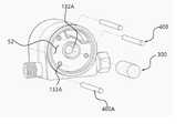
도 4는 본 발명의 자외선 조사 필터 정수장치의 필터부 및 살균부를 설명하기 위한 사시도.
도 5는 본 발명의 자외선 조사 필터 정수장치의 물 배출을 설명하기 위한 단면도.1 is a perspective view showing a UV irradiation filter water purifying device according to the present invention.
Figure 2 is a perspective view and an aberration partially enlarged view for explaining the power generation unit of the ultraviolet irradiation filter water purifying device of the present invention.
Figure 3 is a cross-sectional view for explaining the development of the ultraviolet irradiation filter purifying device of the present invention.
4 is a perspective view illustrating a filter unit and a sterilization unit of the ultraviolet irradiation filter purifying device according to the present invention;
Figure 5 is a cross-sectional view for explaining water discharge of the ultraviolet irradiation filter water purifying device of the present invention.
본 발명의 실시예들에 대한 이점 및 특징, 그리고 그것들을 달성하는 방법은 첨부되는 도면과 함께 상세하게 후술되어 있는 실시예들을 참조하면 명확해질 것이다. 그러나 본 발명은 이하에서 개시되는 실시예들에 한정되는 것이 아니라 서로 다른 다양한 형태로 구현될 수 있으며, 단지 본 실시예들은 본 발명의 개시가 완전하도록 하고, 본 발명이 속하는 기술 분야에서 통상의 지식을 가진 자에게 발명의 범주를 완전하게 알려주기 위해 제공되는 것이며, 본 발명은 청구항의 범주에 의해 정의될 뿐이다. 명세서 전체에 걸쳐 동일 참조 부호는 동일 구성요소를 지칭한다.Advantages and characteristics of the embodiments of the present invention, and methods for achieving them will become clear with reference to the embodiments described below in detail in conjunction with the accompanying drawings. However, the present invention is not limited to the embodiments disclosed below and may be implemented in various different forms, only the present embodiments make the disclosure of the present invention complete, and common knowledge in the art to which the present invention belongs. It is provided to completely inform the person who has the scope of the invention, and the present invention is only defined by the scope of the claims. Like reference numbers designate like elements throughout the specification.
본 발명의 실시예들을 설명함에 있어서 공지 기능 또는 구성에 대한 구체적인 설명이 본 발명의 요지를 불필요하게 흐릴 수 있다고 판단되는 경우에는 그 상세한 설명을 생략할 것이다. 그리고 후술되는 용어들은 본 발명의 실시예에서의 기능을 고려하여 정의된 용어들로서 이는 사용자, 운용자의 의도 또는 관례 등에 따라 달라질 수 있다. 그러므로 그 정의는 본 명세서 전반에 걸친 내용을 토대로 내려져야 할 것이다.In describing the embodiments of the present invention, if it is determined that a detailed description of a known function or configuration may unnecessarily obscure the subject matter of the present invention, the detailed description will be omitted. In addition, terms to be described later are terms defined in consideration of functions in the embodiment of the present invention, which may vary according to the intention or custom of a user or operator. Therefore, the definition should be made based on the contents throughout this specification.
이하, 첨부된 도면을 참조하여 본 발명에 따른 자외선 조사 필터 정수장치(1000)에 관하여 설명하도록 한다.Hereinafter, a UV irradiation filter purifying
도 1은 본 발명의 자외선 조사 필터 정수장치를 나타낸 사시도이고, 도 2는 본 발명의 자외선 조사 필터 정수장치의 발전부를 설명하기 위한 투시도 및 수차 부분 확대도이고, 도 3은 본 발명의 자외선 조사 필터 정수장치의 발전을 설명하기 위한 단면도이고, 도 4는 본 발명의 자외선 조사 필터 정수장치의 필터부 및 살균부를 설명하기 위한 사시도이고, 도 5는 본 발명의 자외선 조사 필터 정수장치의 물 배출을 설명하기 위한 단면도이다.1 is a perspective view showing a UV irradiation filter purifying device of the present invention, FIG. 2 is a perspective view and an enlarged view of an aberration part for explaining a power generation unit of the UV irradiation filter purifying device of the present invention, and FIG. 3 is a UV irradiation filter of the present invention. Figure 4 is a cross-sectional view for explaining the development of a water purifying device, Figure 4 is a perspective view for explaining the filter unit and sterilization unit of the ultraviolet irradiation filter water purifying device of the present invention, Figure 5 explains the water discharge of the ultraviolet irradiation filter water purifying device of the present invention This is a cross-section for
도 1 내지 도 5를 참조하면, 본 발명의 자외선 조사 필터 정수장치는1 to 5, the ultraviolet irradiation filter purifying device of the present invention
유체가 이동하는 이송통로를 형성하는 하우징(100)과,A
상기 이송통로를 통해 이동하는 물을 이용하여 전기를 생산하는 발전부(200)와,A
상기 이송통로를 통해 이동하는 물에 함유된 이물질을 제거하는 필터부(300)와,A
상기 이송통로를 통해 이동하는 물과 상기 필터부(300)로 자외선을 조사하여 살균하는 살균부(400)를 포함할 수 있다.It may include a
상기 하우징(100)은 상기 발전부(200), 필터부(300) 및 살균부(400)가 수용되는 메인 하우징(100A)과,The
상기 메인 하우징(100A)에 결합되어 유체가 유입되는 통로를 형성하는 유입로 형성 하우징(100B)과,An inflow
상기 메인 하우징(100A)에 결합되어 유체가 배출되는 통로를 형성하는 배출로 형성 하우징(100C)을 포함할 수 있다.It may include a
상세히 설명하면. 상기 유입로 형성 하우징(100B)을 통해 유입되는 물은 상기 발전부(200)를 회전시킨 후 상기 필터부(300) 및 살균부(400)가 위치되는 공간으로 이동하고, 상기 살균부(400)에 의해 물과 상기 필터부(300)가 정화되어 상기 배출로 형성 하우징(100C)으로 배출되는 것이다.If explained in detail. The water introduced through the inflow
또한 상기 발전부(200)에서 생산되는 전기는 상기 살균부(400)로 공급되어 살균부(400)에서 지속적으로 자외선을 방출할 수 있게 하고, 방출되는 자외선은 물에 직접 인가되어 물을 정화하거나 필터부(300)에 인가되어 필터부(300)를 살균하여 필터부(300) 오염을 방지할 수 있도록 한 것이다.In addition, electricity generated from the
상기 메인 하우징(100A)은 상기 발전부(200)가 수용되는 제1 메인 하우징(110A)과,The
상기 필터부(300) 및 상기 살균부(400)가 수용되는 제2 메인 하우징(120A)과,A second
상기 제1 메인 하우징(110A)과 상기 제2 메인 하우징(120A) 사이에 위치되어 하우징(100) 내부 공간을 발전부(200)가 위치되는 제1 공간(S1)과 필터부(300)와 살균부(400)가 위치되는 제2 공간(S2)으로 분리하는 격리 플레이트(130A)를 포함할 수 있다.It is located between the first
또한 상기 격리 플레이트(130A)는 상기 제1 공간(S1)에 위치된 유체가 제2 공간(S2)으로 이동하는 통로를 형성하는 제1 가이드홀(131A)과, 제2 공간(S2)에 위치된 유체가 상기 배출로 형성 하우징(100C)으로 이동하는 통로를 형성하는 제2 가이드홀(132A)을 포함할 수 있다.In addition, the
상세히 설명하면, 이동하는 물에 의해 발전이 효과적으로 이루어지기 위해서는, 물의 이동이 발전에 효과적인 형태로 이루어져야 하므로, 격리 플레이트(130A)로 메인 하우징(100A) 내부 공각을 분리하여 발전이 보다 효과적으로 이루어질 수 있는 제1 공간(S1)을 형성하여 준 것이다.In detail, in order for power generation to be effectively achieved by moving water, the movement of water must be performed in an effective form for power generation. It gave the formation of the first space (S1).
또한 발전에 사용된 물이 발전에 사용된 후 상기 제1 가이드홀(131A)을 통해 제2 공간(S2)으로 자연스럽게 이동할 수 있도록 한 것이다.In addition, after the water used for power generation is used for power generation, it is allowed to move naturally to the second space S2 through the
아울러 상기 제2 가이드홀(132A)에 필터부(300)가 결합되어 제2 가이드홀(132A)로 유입되는 물에 함유된 이물질이 필터부(300)에 의해 필터링 되며, 상기 필터부(300)는 물은 통과시키되 물에 함유된 이물질을 필터링 가능한 다공성 구조를 가질 수 있으면 충분하므로, 다양한 형상과 재질로 만들어지는 모든 필터를 포함할 수 있음은 물론이다.In addition, the
아울러, 메인 하우징(100A)은 상기 제2 가이드홀(132A)에 결합된 필터부(300)를 통과하며 정화된 물을 상기 배출로 형성 하우징(100C)으로 가이드하는 배출로 형성부재(140A)를 포함할 수 있고, 상기 배출로 형성부재(140A)는 길이방향 일측이 상기 제2 가이드홀(132A)에 체결되고 길이방향 타측이 상기 배출로 형성 하우징(100C)에 결합되어, 정화된 물이 제1 공간(S1)에 위치된 물과 혼합되지 않고 외부로 배출되는 통로 역할을 한다.In addition, the
또한, 상기 필터부(300)가 미생물 또는 이물질에 의해 오염될 경우 물이 통과하는 공극이 막혀 물 정화능력이 저하되는 문제가 발생할 수 있으므로, 본 발명에서는 상기 살균부(400)에서 필터부(300)에 자외선을 조사하여 필터 오염을 방지할 수 있다.In addition, when the
상기 살균부(400)는 자외선을 조사하여 필터의 오염을 제한할 수 있는 다양한 자외선 방출수단을 포함할 수 있고, 이러한 자외선 인가가 필터부(300) 전방에 고루 이루어질 수 있도록 살균부(400)를 구성하는 복수개의 살균모듈(400A)이 필터부(300)를 중앙에 두고 감싸는 형태로 배치되는 것을 권장한다.The
이때, 상기 살균모듈(400A)이 설정된 위치에 고정될 수 있도록 상기 격리 플레이트(130A)에는 살균모듈(400A)이 결합되는 복수개의 살균부 결합부(133A)가 형성될 수 있다.At this time, a plurality of sterilization
상기 발전부(200)는 상기 제1 공간(S1)으로 유입되는 유체에 의해 회전하는 수차(210)와, 상기 수차(210)와 회전축이 연결되고 수차(210)로부터 회전력을 전달받아 전기를 생산하는 발전수단(220)을 포함할 수 있다.The
또한 상기 발전부(200)에서 생산되는 전기는 상기 살균부(400)로 공급되어 살균부(400)를 작동시킬 수 있으며, 배터리로 공급되어 살균부(400)와 전기적으로 연결된 배터리를 충전시키는 용도로도 사용될 수 있다.In addition, electricity generated from the
발전 효율을 높이고, 발전 과정에서 발생하는 물의 역류를 막기 위해서 상기 수차(210)는 특수한 형상을 가지는 것을 권장하고, 이하에서는 이러한 수차(210)의 특수한 형상에 대하여 설명하도록 한다.It is recommended that the
도 1 내지 도 2를 참조하면, 상기 수차(210)는 중앙에 위치되는 회전몸체(211)와, 상기 회전몸체(211)의 가장자리에 결합되는 수차 블레이드(212)를 포함하고, 상기 수차 블레이드(212)는 중앙에 움푹 파인 형태의 유체 인가홈(212-1)이 형성되는 것을 권장한다.1 and 2, the
상세히 설명하면, 수차 블레이드(212)가 평평한 형상을 가질 경우 상기 유입로 형성 하우징(100B)과 연결된 노즐(101B)을 통해 인가되는 물의 힘이 수차 블레이드(212)에 완벽하게 전달되지 못하기 때문에 에너지 전달 효율이 낮은 문제점이 있으므로, 본 발명에서는 수차 블레이드(212) 중앙에 유체 인가홈(212-1)을 형성하여 노즐(101B)에서 방출되는 물이 수차 블레이드(212)에 온전히 인가될 수 있도록 한 것이다.In detail, when the
이때, 에너지가 보다 효과적으로 전달되기 위하여 유체 인가홈(212-1)은 노즐(101B)과 마주보는 높이에 위치되어야 함은 물론이다.At this time, it goes without saying that the fluid applying groove 212-1 should be located at a height facing the
또한 상기 수차 블레이드(212)는 상기 수차 블레이드(212) 가장자리에 형성되어 유체가 빠져나가는 통로를 형성하는 유체 배출홈(212-2)을 더 포함할 수 있다.In addition, the
상세히 설명하면, 수차 블레이드(212)에 유체 인가홈(212-1) 형성 시 수차 블레이드(212)에 힘을 전달한 유체가 새로 유입되는 유체와 부딪혀 와류가 형성되고, 이러한 와류는 유체의 이동을 저하시켜 정수장치의 단위시간당 정수능력을 낮추는 문제점이 있으므로, 본 발명에서는 수차 블레이드(212)에 유체 배출홈(212-2)을 형성하여 수차 블레이드(212)에 부딪혀 힘을 전달한 물이 뒤에서 유입되는 물에 밀려 유체 배출홈(212-2)으로 빠져나갈 수 있도록 한 것이다.In detail, when the fluid applying groove 212-1 is formed on the
아울러, 상기 수차 블레이드(212)는 상기 유체 인가홈(212-1)이 형성되는 표면에 형성되고, 유체 인가홈(212-1)에 인가된 유체가 상기 유체 배출홈(212-2)으로 이동하는 경로를 형성하는 이동방향 가이드홈(212-3)을 포함할 수 있다.In addition, the
상세히 설명하면, 상기 이동방향 가이드홈(212-3)은 유체가 상기유체 배출홈(212-2)을 향해 이동할 수 있도록 방향을 가이드하여, 유체 이동이 보다 원활하게 이루어질 수 있도록 한 것이다.In detail, the moving direction guide groove 212-3 guides the fluid to move toward the fluid discharge groove 212-2 so that the fluid can move more smoothly.
또한 본 발명의 자외선 조사 필터 정수장치는 상기 하우징(100)에 내부에 수용된 배터리 충전 상태를 표시하는 발전상태 표시부가 형성될 수 있고, 발전상태 표시부는 점등 색깔 또는 점등 상태를 이용하여 사용자에게 충전에 관한 정보를 전달할 수 있다.In addition, in the ultraviolet irradiation filter purifying device of the present invention, a power generation status display unit for displaying the charge state of the battery accommodated therein may be formed in the
아울러 본 발명은 자외선 조사 필터 정수장치; 및 상기 자외선 조사 필터 정수장치와 유무선 통신을 통하여 연결되는 사용자 단말;을 포함하는 자외선 조사 필터 정수장치 시스템에 관한 것이다.In addition, the present invention is a UV irradiation filter purifying device; and a user terminal connected to the ultraviolet irradiation filter purifying device through wired or wireless communication.
상기 자외선 조사 필터 정수장치는 유무선 통신을 통하여 사용자 단말과 연결될 수 있으며, 상기 사용자 단말은 상기 자외선 조사 필터 정수장치의 작동, 관리, 정보 확인 등을 위한 어플리케이션을 포함할 수 있다.The UV irradiation filter purifying device may be connected to a user terminal through wired or wireless communication, and the user terminal may include an application for operating, managing, and checking information of the UV irradiation filter purifying device.
상기 사용자 단말을 통해 자외선 조사 필터 정수장치의 작동상태, 작동시간, 작동이력, 필터의 살균시간 및 살균이력, 물 사용량, 수도세, 전기세, 전기 발전량, 필터의 사용시간 및 오염도, 필터교환시기 등의 정보를 확인할 수 있고, 자외선 조사 필터 정수장치의 on/off, 필터의 살균 on/off 등을 조절할 수 있다.Through the user terminal, the operation status, operation time, operation history, filter sterilization time and sterilization history, water usage, water bill, electricity bill, electricity generation amount, filter usage time and pollution degree, filter replacement time, etc. Information can be checked, and the on/off of the UV irradiation filter purifying device and the sterilization on/off of the filter can be adjusted.
또한 상기 정보로부터 필터의 A/S 신청, 필터의 교환, 살균부의 교체 및 수리, 자외선 조사 필터 정수장치의 수리 및 교체 등을 요청할 수 있다.In addition, from the above information, it is possible to request filter A/S, filter exchange, replacement and repair of a sterilization unit, repair and replacement of an ultraviolet irradiation filter purifying device, and the like.
상기 자외선 조사 필터 정수장치는 상기 발전부(200)의 수차 블레이드(212)의 회전수로부터 발전량, 물 사용량, 수도세, 전기세 등을 도출할 수 있으며, 도출된 정보를 유무선 통신장치를 통해 사용자 단말로 전달할 수 있다.The ultraviolet irradiation filter purifying device may derive power generation, water usage, water bill, electricity bill, etc. from the number of revolutions of the
100 : 하우징100A : 메인 하우징
110A : 제1 메인 하우징120A : 제2 메인 하우징
130A : 격리 플레이트131A : 제1 가이드홀
132A : 제2 가이드홀133A : 살균부 결합부
140A : 배출로 형성부재
100B : 유입로 형성 하우징100C : 배출로 형성 하우징
200 : 발전부210 : 수차
211 : 회전몸체212 : 수차 블레이드
212-1 : 유체 인가홈212-2 : 유체 배출홈
212-3 : 이동방향 가이드홈
220 : 발전수단
300 : 필터부
400 : 살균부400A : 살균모듈100:
110A: first
130A:
132A:
140A: discharge path forming member
100B:
200: power generation unit 210: aberration
211: rotating body 212: water wheel blade
212-1: fluid supply groove 212-2: fluid discharge groove
212-3: moving direction guide groove
220: power generation means
300: filter unit
400:
Claims (7)
Translated fromKorean상기 이송통로를 통해 이동하는 물을 이용하여 전기를 생산하는 발전부(200);
상기 이송통로를 통해 이동하는 물에 함유된 이물질을 제거하는 필터부(300); 및
상기 이송통로를 통해 이동하는 물과 상기 필터부(300)로 자외선을 조사하여 살균하는 살균부(400);를 포함하는 자외선 조사 필터 정수장치에 있어서,
상기 하우징(100)은
상기 발전부(200), 필터부(300) 및 살균부(400)가 수용되는 메인 하우징(100A);
상기 메인 하우징(100A)에 결합되어 유체가 유입되는 통로를 형성하는 유입로 형성 하우징(100B); 및
상기 메인 하우징(100A)에 결합되어 유체가 배출되는 통로를 형성하는 배출로 형성 하우징(100C);을 포함하고,
상기 메인 하우징(100A)은
상기 발전부(200)가 수용되는 제1 메인 하우징(110A);
상기 필터부(300) 및 상기 살균부(400)가 수용되는 제2 메인 하우징(120A); 및
상기 제1 메인 하우징(110A)과 상기 제2 메인 하우징(120A) 사이에 위치되어 하우징(100) 내부 공간을 발전부(200)가 위치되는 제1 공간(S1)과 필터부(300)와 살균부(400)가 위치되는 제2 공간(S2)으로 분리하는 격리 플레이트(130A);를 포함하며,
상기 격리 플레이트(130A)는
상기 제1 공간(S1)에 위치된 유체가 제2 공간(S2)으로 이동하는 통로를 형성하는 제1 가이드홀(131A);
상기 제2 공간(S2)에 위치된 유체가 상기 배출로 형성 하우징(100C)으로 이동하는 통로를 형성하는 제2 가이드홀(132A); 및
상기 살균부(400)가 결합되는 살균부 결합부(133A);를 포함하는 것을 특징으로 하는 자외선 조사 필터 정수장치.
A housing 100 forming a transfer passage through which fluid moves;
a power generation unit 200 generating electricity using water moving through the transfer passage;
a filter unit 300 for removing foreign substances contained in the water moving through the transfer passage; and
In the ultraviolet irradiation filter water purifying device including a sterilization unit 400 for sterilizing by irradiating ultraviolet rays to the water moving through the transfer passage and the filter unit 300,
The housing 100 is
a main housing 100A accommodating the power generation unit 200, the filter unit 300, and the sterilization unit 400;
an inflow path formed housing 100B coupled to the main housing 100A to form a passage through which fluid flows; and
A housing 100C coupled to the main housing 100A to form a passage through which fluid is discharged; a housing 100C;
The main housing 100A is
a first main housing 110A in which the power generation unit 200 is accommodated;
a second main housing 120A accommodating the filter unit 300 and the sterilization unit 400; and
It is located between the first main housing 110A and the second main housing 120A and sterilizes the inner space of the housing 100 with the first space S1 where the power generation unit 200 is located and the filter unit 300 It includes; an isolation plate (130A) separating the second space (S2) in which the unit 400 is located;
The isolation plate 130A is
a first guide hole 131A forming a passage through which the fluid located in the first space S1 moves to the second space S2;
a second guide hole 132A forming a passage through which the fluid located in the second space S2 moves to the housing 100C forming the discharge passage; and
An ultraviolet irradiation filter water purifying device comprising a; sterilization unit coupling portion 133A to which the sterilization unit 400 is coupled.
상기 발전부(200)는 상기 제1 공간(S1)으로 유입되는 유체에 의해 회전하는 수차(210); 및
상기 수차(210)와 회전축이 연결되고, 수차(210)로부터 회전력을 전달받아 전기를 생산하는 발전수단(220)을 포함하는 것을 특징으로 하는 자외선 조사 필터 정수장치.
According to claim 1,
The power generation unit 200 includes a water turbine 210 rotating by the fluid flowing into the first space S1; and
The water turbine 210 and the rotating shaft are connected, and the ultraviolet irradiation filter water purifying device characterized in that it comprises a power generation means 220 for generating electricity by receiving rotational force from the water turbine 210.
상기 수차(210)는
중앙에 위치되는 회전몸체(211); 및
상기 회전몸체(211)의 가장자리에 결합되는 수차 블레이드(212);를 포함하고,
상기 수차 블레이드(212)는 중앙에 움푹 파인 형태의 유체 인가홈(212-1)이 형성되는 것을 특징으로 하는 자외선 조사 필터 정수장치.
According to claim 5,
The aberration 210 is
Rotating body 211 located in the center; and
A water turbine blade 212 coupled to the edge of the rotating body 211; includes,
The water turbine blade 212 is a UV irradiation filter water purifying device, characterized in that a concave fluid applying groove 212-1 is formed in the center.
상기 자외선 조사 필터 정수장치와 유무선 통신을 통하여 연결되는 사용자 단말;을 포함하는 자외선 조사 필터 정수장치 시스템.
The ultraviolet irradiation filter water purifier of claim 1; and
A user terminal connected to the ultraviolet irradiation filter water purification device through wired or wireless communication.
Priority Applications (1)
| Application Number | Priority Date | Filing Date | Title |
|---|---|---|---|
| KR1020220108880AKR102466113B1 (en) | 2022-08-30 | 2022-08-30 | AESD ultraviolet radiated filter and system using eco-friendly energy |
Applications Claiming Priority (1)
| Application Number | Priority Date | Filing Date | Title |
|---|---|---|---|
| KR1020220108880AKR102466113B1 (en) | 2022-08-30 | 2022-08-30 | AESD ultraviolet radiated filter and system using eco-friendly energy |
Publications (1)
| Publication Number | Publication Date |
|---|---|
| KR102466113B1true KR102466113B1 (en) | 2022-11-11 |
Family
ID=84042798
Family Applications (1)
| Application Number | Title | Priority Date | Filing Date |
|---|---|---|---|
| KR1020220108880AActiveKR102466113B1 (en) | 2022-08-30 | 2022-08-30 | AESD ultraviolet radiated filter and system using eco-friendly energy |
Country Status (1)
| Country | Link |
|---|---|
| KR (1) | KR102466113B1 (en) |
Citations (6)
| Publication number | Priority date | Publication date | Assignee | Title |
|---|---|---|---|---|
| JPS6035794U (en)* | 1983-08-19 | 1985-03-12 | 株式会社 タコ− | Water purification filter |
| KR100771768B1 (en)* | 2003-10-09 | 2007-10-30 | 액세스 비지니스 그룹 인터내셔날 엘엘씨 | Self-Powered Small Liquid Handling System |
| KR20100074139A (en)* | 2007-09-27 | 2010-07-01 | 워터 오브 라이프, 엘엘씨 | Ultraviolet water purification system |
| KR20180053819A (en) | 2016-11-14 | 2018-05-24 | 오환종 | The water purifying cap with UV(ultraviolet ravs) led of self generation electricity type and filter |
| CN211302278U (en)* | 2019-11-15 | 2020-08-21 | 广东万家乐燃气具有限公司 | From leading filter of taking electricity generation and UV function of disinfecting |
| KR20220064278A (en) | 2020-11-11 | 2022-05-18 | 주식회사 현태 | Integrated solar power generation and water purification system |
- 2022
- 2022-08-30KRKR1020220108880Apatent/KR102466113B1/enactiveActive
Patent Citations (6)
| Publication number | Priority date | Publication date | Assignee | Title |
|---|---|---|---|---|
| JPS6035794U (en)* | 1983-08-19 | 1985-03-12 | 株式会社 タコ− | Water purification filter |
| KR100771768B1 (en)* | 2003-10-09 | 2007-10-30 | 액세스 비지니스 그룹 인터내셔날 엘엘씨 | Self-Powered Small Liquid Handling System |
| KR20100074139A (en)* | 2007-09-27 | 2010-07-01 | 워터 오브 라이프, 엘엘씨 | Ultraviolet water purification system |
| KR20180053819A (en) | 2016-11-14 | 2018-05-24 | 오환종 | The water purifying cap with UV(ultraviolet ravs) led of self generation electricity type and filter |
| CN211302278U (en)* | 2019-11-15 | 2020-08-21 | 广东万家乐燃气具有限公司 | From leading filter of taking electricity generation and UV function of disinfecting |
| KR20220064278A (en) | 2020-11-11 | 2022-05-18 | 주식회사 현태 | Integrated solar power generation and water purification system |
Similar Documents
| Publication | Publication Date | Title |
|---|---|---|
| AU2010315119B2 (en) | Photochemical purification of fluids | |
| US8506886B2 (en) | Ultraviolet photoreactor for the purification of fluids | |
| JP2024023765A (en) | Air cleaner | |
| KR100997378B1 (en) | Photocatalyst using porous pipe and air purifier using the same | |
| KR102084775B1 (en) | Air sterilization module and air purifier using it | |
| US20210292193A1 (en) | Water purifying apparatus and method | |
| CN101300195A (en) | Ultraviolet irradiation water-treatment apparatus | |
| KR102432453B1 (en) | Air sterilization module and air purifier using it | |
| CN102056848A (en) | Photochemical reactor, luminescent screen and photochemical processing system | |
| KR102466113B1 (en) | AESD ultraviolet radiated filter and system using eco-friendly energy | |
| JP2018196620A (en) | Washing machine | |
| KR102148131B1 (en) | Air Cleaner Apparatus Using Photocatalyst | |
| KR20200113726A (en) | Ultraviolet Advanced Oxidation Process reactor and water treatment system containing the same | |
| EP2953902B1 (en) | Uv apparatus | |
| CN119121575A (en) | A water purification and sterilization device for washing machine | |
| TWM657689U (en) | Water purification equipment | |
| TWM657941U (en) | Shock absorbing device for booster pump of water purification equipment | |
| JP3612150B2 (en) | Water treatment equipment | |
| CA2582467C (en) | Systems and methods for in-situ cleaning of protective sleeves in uv decontamination systems | |
| JP2014046306A (en) | Water sterilizing apparatus | |
| KR102697576B1 (en) | A SMART RUNNING WATER DISINFECTION MODULATABLE DEVICE WITH SENSOR AND IoT DEVICE | |
| KR100955301B1 (en) | Water sterilizer using ultraviolet lamp | |
| KR102741539B1 (en) | Sterilization and disinfection system using engine power combined cavitation | |
| CN217838432U (en) | Medium-pressure water treatment device | |
| KR102361559B1 (en) | Photocatalytic Purifier |
Legal Events
| Date | Code | Title | Description |
|---|---|---|---|
| PA0109 | Patent application | St.27 status event code:A-0-1-A10-A12-nap-PA0109 | |
| PA0201 | Request for examination | St.27 status event code:A-1-2-D10-D11-exm-PA0201 | |
| PA0302 | Request for accelerated examination | St.27 status event code:A-1-2-D10-D17-exm-PA0302 St.27 status event code:A-1-2-D10-D16-exm-PA0302 | |
| D13-X000 | Search requested | St.27 status event code:A-1-2-D10-D13-srh-X000 | |
| D14-X000 | Search report completed | St.27 status event code:A-1-2-D10-D14-srh-X000 | |
| E13-X000 | Pre-grant limitation requested | St.27 status event code:A-2-3-E10-E13-lim-X000 | |
| P11-X000 | Amendment of application requested | St.27 status event code:A-2-2-P10-P11-nap-X000 | |
| P13-X000 | Application amended | St.27 status event code:A-2-2-P10-P13-nap-X000 | |
| E701 | Decision to grant or registration of patent right | ||
| PE0701 | Decision of registration | St.27 status event code:A-1-2-D10-D22-exm-PE0701 | |
| GRNT | Written decision to grant | ||
| PR0701 | Registration of establishment | St.27 status event code:A-2-4-F10-F11-exm-PR0701 | |
| PR1002 | Payment of registration fee | St.27 status event code:A-2-2-U10-U11-oth-PR1002 Fee payment year number:1 | |
| PG1601 | Publication of registration | St.27 status event code:A-4-4-Q10-Q13-nap-PG1601 | |
| P14-X000 | Amendment of ip right document requested | St.27 status event code:A-5-5-P10-P14-nap-X000 | |
| PN2301 | Change of applicant | St.27 status event code:A-5-5-R10-R11-asn-PN2301 | |
| P16-X000 | Ip right document amended | St.27 status event code:A-5-5-P10-P16-nap-X000 | |
| PN2301 | Change of applicant | St.27 status event code:A-5-5-R10-R14-asn-PN2301 | |
| R18-X000 | Changes to party contact information recorded | St.27 status event code:A-5-5-R10-R18-oth-X000 | |
| R18-X000 | Changes to party contact information recorded | St.27 status event code:A-5-5-R10-R18-oth-X000 | |
| PR1001 | Payment of annual fee | St.27 status event code:A-4-4-U10-U11-oth-PR1001 Fee payment year number:4 |