KR102465904B1 - Automatic transmission for vehicle - Google Patents
Automatic transmission for vehicleDownload PDFInfo
- Publication number
- KR102465904B1 KR102465904B1KR1020170160103AKR20170160103AKR102465904B1KR 102465904 B1KR102465904 B1KR 102465904B1KR 1020170160103 AKR1020170160103 AKR 1020170160103AKR 20170160103 AKR20170160103 AKR 20170160103AKR 102465904 B1KR102465904 B1KR 102465904B1
- Authority
- KR
- South Korea
- Prior art keywords
- slider
- rotating shaft
- vehicle
- diaphragm spring
- unit
- Prior art date
- Legal status (The legal status is an assumption and is not a legal conclusion. Google has not performed a legal analysis and makes no representation as to the accuracy of the status listed.)
- Active
Links
- 230000005540biological transmissionEffects0.000titleclaimsabstractdescription39
- 230000008878couplingEffects0.000claimsabstractdescription3
- 238000010168coupling processMethods0.000claimsabstractdescription3
- 238000005859coupling reactionMethods0.000claimsabstractdescription3
- 230000000630rising effectEffects0.000claimsabstractdescription3
- 230000006835compressionEffects0.000claimsdescription48
- 238000007906compressionMethods0.000claimsdescription48
- 238000000034methodMethods0.000claimsdescription9
- 230000002040relaxant effectEffects0.000claimsdescription3
- 238000010586diagramMethods0.000description7
- 230000001360synchronised effectEffects0.000description4
- 229910003460diamondInorganic materials0.000description1
- 239000010432diamondSubstances0.000description1
- 230000009977dual effectEffects0.000description1
- 239000000446fuelSubstances0.000description1
Images


Classifications
- F—MECHANICAL ENGINEERING; LIGHTING; HEATING; WEAPONS; BLASTING
- F16—ENGINEERING ELEMENTS AND UNITS; GENERAL MEASURES FOR PRODUCING AND MAINTAINING EFFECTIVE FUNCTIONING OF MACHINES OR INSTALLATIONS; THERMAL INSULATION IN GENERAL
- F16H—GEARING
- F16H61/00—Control functions within control units of change-speed- or reversing-gearings for conveying rotary motion ; Control of exclusively fluid gearing, friction gearing, gearings with endless flexible members or other particular types of gearing
- F16H61/02—Control functions within control units of change-speed- or reversing-gearings for conveying rotary motion ; Control of exclusively fluid gearing, friction gearing, gearings with endless flexible members or other particular types of gearing characterised by the signals used
- F16H61/0293—Control functions within control units of change-speed- or reversing-gearings for conveying rotary motion ; Control of exclusively fluid gearing, friction gearing, gearings with endless flexible members or other particular types of gearing characterised by the signals used the signals being purely mechanical
- F16H61/0295—Automatic gear shift control, e.g. initiating shift by centrifugal forces
- F—MECHANICAL ENGINEERING; LIGHTING; HEATING; WEAPONS; BLASTING
- F16—ENGINEERING ELEMENTS AND UNITS; GENERAL MEASURES FOR PRODUCING AND MAINTAINING EFFECTIVE FUNCTIONING OF MACHINES OR INSTALLATIONS; THERMAL INSULATION IN GENERAL
- F16D—COUPLINGS FOR TRANSMITTING ROTATION; CLUTCHES; BRAKES
- F16D23/00—Details of mechanically-actuated clutches not specific for one distinct type
- F16D23/02—Arrangements for synchronisation, also for power-operated clutches
- F16D23/10—Arrangements for synchronisation, also for power-operated clutches automatically producing the engagement of the clutch when the clutch members are moving at the same speed; Indicating synchronisation
- F—MECHANICAL ENGINEERING; LIGHTING; HEATING; WEAPONS; BLASTING
- F16—ENGINEERING ELEMENTS AND UNITS; GENERAL MEASURES FOR PRODUCING AND MAINTAINING EFFECTIVE FUNCTIONING OF MACHINES OR INSTALLATIONS; THERMAL INSULATION IN GENERAL
- F16H—GEARING
- F16H3/00—Toothed gearings for conveying rotary motion with variable gear ratio or for reversing rotary motion
- F16H3/006—Toothed gearings for conveying rotary motion with variable gear ratio or for reversing rotary motion power being selectively transmitted by parallel flow paths, e.g. dual clutch transmissions
- F—MECHANICAL ENGINEERING; LIGHTING; HEATING; WEAPONS; BLASTING
- F16—ENGINEERING ELEMENTS AND UNITS; GENERAL MEASURES FOR PRODUCING AND MAINTAINING EFFECTIVE FUNCTIONING OF MACHINES OR INSTALLATIONS; THERMAL INSULATION IN GENERAL
- F16H—GEARING
- F16H61/00—Control functions within control units of change-speed- or reversing-gearings for conveying rotary motion ; Control of exclusively fluid gearing, friction gearing, gearings with endless flexible members or other particular types of gearing
- F16H61/68—Control functions within control units of change-speed- or reversing-gearings for conveying rotary motion ; Control of exclusively fluid gearing, friction gearing, gearings with endless flexible members or other particular types of gearing specially adapted for stepped gearings
- F16H61/684—Control functions within control units of change-speed- or reversing-gearings for conveying rotary motion ; Control of exclusively fluid gearing, friction gearing, gearings with endless flexible members or other particular types of gearing specially adapted for stepped gearings without interruption of drive
- F16H61/688—Control functions within control units of change-speed- or reversing-gearings for conveying rotary motion ; Control of exclusively fluid gearing, friction gearing, gearings with endless flexible members or other particular types of gearing specially adapted for stepped gearings without interruption of drive with two inputs, e.g. selection of one of two torque-flow paths by clutches
- F—MECHANICAL ENGINEERING; LIGHTING; HEATING; WEAPONS; BLASTING
- F16—ENGINEERING ELEMENTS AND UNITS; GENERAL MEASURES FOR PRODUCING AND MAINTAINING EFFECTIVE FUNCTIONING OF MACHINES OR INSTALLATIONS; THERMAL INSULATION IN GENERAL
- F16H—GEARING
- F16H63/00—Control outputs from the control unit to change-speed- or reversing-gearings for conveying rotary motion or to other devices than the final output mechanism
- F16H63/02—Final output mechanisms therefor; Actuating means for the final output mechanisms
- F16H63/04—Final output mechanisms therefor; Actuating means for the final output mechanisms a single final output mechanism being moved by a single final actuating mechanism
- F16H63/06—Final output mechanisms therefor; Actuating means for the final output mechanisms a single final output mechanism being moved by a single final actuating mechanism the final output mechanism having an indefinite number of positions
- F16H63/067—Final output mechanisms therefor; Actuating means for the final output mechanisms a single final output mechanism being moved by a single final actuating mechanism the final output mechanism having an indefinite number of positions mechanical actuating means
- F—MECHANICAL ENGINEERING; LIGHTING; HEATING; WEAPONS; BLASTING
- F16—ENGINEERING ELEMENTS AND UNITS; GENERAL MEASURES FOR PRODUCING AND MAINTAINING EFFECTIVE FUNCTIONING OF MACHINES OR INSTALLATIONS; THERMAL INSULATION IN GENERAL
- F16H—GEARING
- F16H63/00—Control outputs from the control unit to change-speed- or reversing-gearings for conveying rotary motion or to other devices than the final output mechanism
- F16H63/02—Final output mechanisms therefor; Actuating means for the final output mechanisms
- F16H63/30—Constructional features of the final output mechanisms
- F16H63/32—Gear shift yokes, e.g. shift forks
- F—MECHANICAL ENGINEERING; LIGHTING; HEATING; WEAPONS; BLASTING
- F16—ENGINEERING ELEMENTS AND UNITS; GENERAL MEASURES FOR PRODUCING AND MAINTAINING EFFECTIVE FUNCTIONING OF MACHINES OR INSTALLATIONS; THERMAL INSULATION IN GENERAL
- F16H—GEARING
- F16H2200/00—Transmissions for multiple ratios
- F16H2200/003—Transmissions for multiple ratios characterised by the number of forward speeds
- F16H2200/0034—Transmissions for multiple ratios characterised by the number of forward speeds the gear ratios comprising two forward speeds
- F—MECHANICAL ENGINEERING; LIGHTING; HEATING; WEAPONS; BLASTING
- F16—ENGINEERING ELEMENTS AND UNITS; GENERAL MEASURES FOR PRODUCING AND MAINTAINING EFFECTIVE FUNCTIONING OF MACHINES OR INSTALLATIONS; THERMAL INSULATION IN GENERAL
- F16H—GEARING
- F16H2708/00—Control devices for speed-changing geared mechanisms, e.g. specially adapted couplings for synchronising devices, devices to simplify control, control of auxiliary gearboxes
- F16H2708/16—Control devices for speed-changing geared mechanisms, e.g. specially adapted couplings for synchronising devices, devices to simplify control, control of auxiliary gearboxes wherein the gearing is not described or not essential
- F16H2708/18—Control devices for speed-changing geared mechanisms, e.g. specially adapted couplings for synchronising devices, devices to simplify control, control of auxiliary gearboxes wherein the gearing is not described or not essential the control being mechanical
Landscapes
- Engineering & Computer Science (AREA)
- General Engineering & Computer Science (AREA)
- Mechanical Engineering (AREA)
- Gear-Shifting Mechanisms (AREA)
- Mechanical Operated Clutches (AREA)
Abstract
Translated fromKoreanDescription
Translated fromKorean본 발명은 차량용 변속장치에 관한 것으로, 보다 상세하게는 차량용 자동 변속장치에 관한 것이다.The present invention relates to a transmission for vehicles, and more particularly to an automatic transmission for vehicles.
일반적으로 자동변속기는 복수의 유성기어세트 조합에 의해 구현되며, 토크 컨버터로부터 전달되는 회전동력을 다단으로 자동 변속하여 출력축에 전달하는 기능을 한다. 또한, 자동변속기는 구현 가능한 변속단이 많을 수록 보다 적절한 변속비의 설계가 가능할 뿐만 아니라, 동력성능 및 연비 면에서 우수한 차량을 구현할 수 있기 때문에, 보다 많은 변속단을 구현하기 위해 꾸준한 연구가 이루어지고 있다.In general, an automatic transmission is implemented by a combination of a plurality of planetary gear sets, and functions to transmit rotational power transmitted from a torque converter to an output shaft by automatically shifting gears in multiple stages. In addition, since the automatic transmission can implement a vehicle with excellent power performance and fuel efficiency as well as designing a more appropriate transmission ratio as the number of possible shift stages increases, continuous research is being conducted to implement more gear stages. .
한편, 자동변속기가 적용된 차량은 기 설정된 변속패턴에 기반하여 변속이 자동적으로 이루어지도록 마련된다. 보다 구체적으로, 기 설정된 변속패턴을 기준으로 차속 및 가속페달 답입량에 따라 다수의 싱크로나이저들이 치합 또는 해제되도록 제어함으로써, 목표 변속단으로 변속이 이루어지도록 마련되는 것이다.Meanwhile, a vehicle to which an automatic transmission is applied is prepared to automatically shift gears based on a preset shift pattern. More specifically, a plurality of synchronizers are controlled to be engaged or disengaged according to the vehicle speed and the amount of depression of the accelerator pedal based on a preset shift pattern, so that shifts are made to a target gear range.
하지만, 이를 위해서는 차속을 감지하는 차속센서, APS(Accelerator pedal sensor) 등을 통해 검출된 데이터를 기 설정된 변속패턴에 기반하여, 다수의 싱크로나이저들을 변속단기어에 치합 또는 해제되도록 제어하는 제어유닛이 요구됐다.However, for this purpose, a control unit controls a plurality of synchronizers to engage or disengage gears based on data detected through a vehicle speed sensor and an accelerator pedal sensor (APS) that detect vehicle speed, etc., based on a preset shift pattern. it was demanded
상기의 배경기술로서 설명된 사항들은 본 발명의 배경에 대한 이해 증진을 위한 것일 뿐, 이 기술분야에서 통상의 지식을 가진자에게 이미 알려진 종래기술에 해당함을 인정하는 것으로 받아들여져서는 안 될 것이다.The matters described as the background art above are only for improving understanding of the background of the present invention, and should not be taken as an admission that they correspond to prior art already known to those skilled in the art.
본 발명은 차량 변속을 위해 다수의 싱크로나이저들이 변속단 기어에 전자적인 제어를 통해 치합 또는 해제되도록 하는 전자적인 제어기를 구비하지 않고, 차속에 따른 기계적인 동작에 의해 다수의 싱크로나이저들이 변속단 기어에 치합 또는 해제되도록 함으로써 자동으로 변속이 수행될 수 있는 차량용 자동 변속장치를 제공하는데 그 목적이 있다.The present invention does not include an electronic controller that allows a plurality of synchronizers to engage or disengage a shift stage gear through electronic control for vehicle shifting, and a plurality of synchronizers are moved by a mechanical operation according to the vehicle speed. An object of the present invention is to provide an automatic transmission for a vehicle in which gear shifting can be performed automatically by engaging or disengaging the gearbox.
상기의 목적을 달성하기 위한 본 발명에 따른 차량용 자동 변속장치는, 차량의 구동력에 의해 회전하는 회전축; 회전축 상에 구비되며 회전축의 축방향을 따라 슬라이딩하도록 마련된 슬라이더부; 일단이 회전축에 힌지결합을 통해 연결되고, 회전축이 회전함에 따라 타단이 원심력에 의해 상승 또는 하강하는 제1연결부재; 일단이 제1연결부재 상에 힌지결합되며, 타단이 슬라이더부에 연결되어 제1연결부재가 상승 또는 하강함에 따라 슬라이더부가 상하 슬라이딩되도록 하는 제2연결부재; 슬라이더부에 결합되며 슬라이더부의 위치에 따라 회전축의 축방향의 일측 또는 타측으로 변형되는 다이아프램 스프링; 슬라이더부 또는 다이아프램 스프링에 연결되며, 슬라이더부의 위치에 따라 동기장치를 변속단 기어에 치합시키는 시프트포크; 다이아프램 스프링의 탄성력을 조절하는 탄성 조절부; 및 차량의 속도에 따라 탄성 조절부를 제어하여 다이아프램 스프링의 탄성력을 조절하는 제어부;를 포함할 수 있다.An automatic transmission for a vehicle according to the present invention for achieving the above object includes a rotating shaft that rotates by the driving force of the vehicle; a slider provided on the rotating shaft and provided to slide along the axial direction of the rotating shaft; a first connecting member having one end connected to the rotating shaft through a hinge coupling and the other end rising or falling by centrifugal force as the rotating shaft rotates; a second linking member having one end hinged on the first linking member and the other end connected to the slider so that the slider slides up and down as the first linking member rises or falls; a diaphragm spring coupled to the slider unit and deformed to one side or the other side in the axial direction of the rotating shaft according to the position of the slider unit; a shift fork connected to the slider part or the diaphragm spring and engaging the synchronizing device with the shift stage gear according to the position of the slider part; Elasticity control unit for adjusting the elastic force of the diaphragm spring; and a controller controlling the elastic force of the diaphragm spring by controlling the elastic controller according to the speed of the vehicle.
회전축 상에 마련되며 제1연결부재의 일단이 힌지결합하는 제1링크부; 회전축 상에 마련되되 제1링크부의 하방에 마련되고 제2연결부재의 타단이 힌지결합되며 하면이 슬라이더부와 결합된 제2링크부; 및 회전축 상에 마련되며 제1링크부와 제2링크부 사이에 배치되고 탄성력을 가하도록 마련된 압축스프링;을 더 포함할 수 있다.A first link portion provided on a rotating shaft and having one end of the first connecting member hinged; A second link part provided on the rotating shaft, provided below the first link part, the other end of the second connecting member is hinged, and the lower surface is coupled to the slider part; and a compression spring provided on the rotating shaft and disposed between the first link unit and the second link unit and provided to apply an elastic force.
탄성 조절부는 압축스프링을 압축 또는 이완시켜 슬라이더부가 회전축의 축방향을 따라 상하 슬라이딩 되도록 하고, 슬라이더부를 회전축의 축방향을 따라 상하 슬라이딩시킴으로써 다이아프램 스프링의 탄성력을 조절할 수 있다.The elasticity adjusting unit compresses or relaxes the compression spring so that the slider part slides up and down along the axial direction of the rotation shaft, and the elastic force of the diaphragm spring can be adjusted by sliding the slider part up and down along the axial direction of the rotation shaft.
제어부는 차량의 속도에 따라 탄성 조절부를 제어하여 압축스프링을 압축 또는 이완시켜 슬라이더부를 회전축의 축방향을 따라 상하 슬라이딩시키고, 슬라이더부를 회전축의 축방향을 따라 상하 슬라이딩시킴으로써 다이아프램 스프링의 탄성력을 조절할 수 있다.The control unit controls the elastic adjustment unit according to the speed of the vehicle to compress or relax the compression spring so that the slider unit slides up and down along the axial direction of the rotation shaft, and the elastic force of the diaphragm spring can be adjusted by sliding the slider unit up and down along the axial direction of the rotation shaft. have.
탄성 조절부는, 모터; 회전축 상에 마련되며 모터와 연결된 캠기어; 회전축 상에 마련되며 캠기어와 일체로 구성된 베이스부; 및 회전축 상에 마련되며 베이스부과 압축스프링 사이에 위치하고, 모터가 회전함에 따라 상하로 이동하여 압축스프링을 압축 또는 이완시키는 압축스프링 위치 조절부;를 포함하여 구성될 수 있다.The elastic control unit, the motor; A cam gear provided on a rotating shaft and connected to the motor; a base portion provided on a rotating shaft and integrally formed with a cam gear; and a compression spring position adjusting unit provided on the rotating shaft and located between the base portion and the compression spring and moving up and down as the motor rotates to compress or relax the compression spring.
탄성 조절부는, 압축스프링 상방에 위치하는 실린더; 실린더에 압력을 제공하는 압력제공부; 및 실린더 내부에 위치하며 압축스프링 상방에 위치하고, 실린더에 압력이 제공됨에 따라 상하로 이동하여 압축스프링을 압축 또는 이완시키는 피스톤;을 포함하여 구성될 수 있다.The elastic control unit, a cylinder located above the compression spring; a pressure providing unit providing pressure to the cylinder; and a piston located inside the cylinder and located above the compression spring, moving up and down as pressure is applied to the cylinder to compress or relax the compression spring.
탄성 조절부는, 서로 같은 극이며, 이격되어 상하에 위치하는 한쌍의 자기체; 및 하방에 위치한 자기체의 하면과 결합되며 압축스프링 상방에 위치하고 자기체의 자력이 변화됨에 따라 상하로 이동하여 압축스프링을 압축 또는 이완시키는 피스톤;을 포함하여 구성될 수 있다.The elastic control unit is the same pole as each other, and is spaced apart from a pair of magnetic bodies located up and down; and a piston coupled to the lower surface of the magnetic body located below, located above the compression spring, and moving up and down as the magnetic force of the magnetic body changes, compressing or relaxing the compression spring.
다이아프램 스프링은 기 설정된 변형량에 도달할 경우에 회전축의 축방향의 일측 또는 타측으로 변형되도록 마련되고, 시프트포크는 다이아프램 스프링이 변형되는 시점에 동기장치가 변속단기어에 치합되기 시작하도록 다이아프램 스프링 또는 슬라이더부에 연결될 수 있다.The diaphragm spring is provided to be deformed to one side or the other side of the axial direction of the rotating shaft when a predetermined amount of deformation is reached, and the shift fork is a diaphragm so that the synchronizing device starts to engage with the shift gear when the diaphragm spring is deformed. It can be connected to a spring or slider part.
시프트포크는 다이아프램 스프링 또는 슬라이더부에 고정결합되어 일체로 슬라이딩되도록 마련될 수 있다.The shift fork is fixedly coupled to the diaphragm spring or the slider unit and may be provided to slide integrally.
본 발명에 따르면 차량 변속을 위해 다수의 동기장치들이 변속단 기어에 전자적인 제어를 통해 치합 또는 해제되도록 하는 전자적인 제어기를 구비하지 않고, 차속에 따른 기계적인 동작에 의해 다수의 동기장치들이 변속단 기어에 치합 또는 해제되도록 함으로써 자동으로 변속이 수행되도록 할 수 있다.According to the present invention, a plurality of synchronous devices are not provided with an electronic controller for engaging or disengaging a plurality of synchronous devices through electronic control to engage or disengage a plurality of synchronous devices for vehicle shifting by mechanical operation according to the vehicle speed. Gear shifting can be performed automatically by engaging or disengaging the gear.
또한, 본 발명에 따르면, 제어부에서 차량의 속도에 따라 탄성 조절부를 제어하여 압축스프링을 압축 또는 이완시켜 슬라이더부를 회전축의 축방향을 따라 상하 슬라이딩시키고, 슬라이더부를 회전축의 축방향을 따라 상하 슬라이딩시켜 다이아프램 스프링의 탄성력을 조절함으로써 다양한 차속의 범위에서 적절하게 변속이 이루어지도록 할 수 있다.In addition, according to the present invention, the control unit controls the elastic adjustment unit according to the speed of the vehicle to compress or relax the compression spring so that the slider unit slides up and down along the axial direction of the rotation shaft, and slides the slider unit up and down along the axial direction of the rotation shaft. By adjusting the elastic force of the spram spring, it is possible to properly shift gears in various vehicle speed ranges.
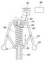
도 1은 본 발명의 일 실시예에 따른 차량용 자동 변속장치에서, 차량이 저속 주행할 시 차량용 자동 변속장치의 작동 모습을 도시한 도면이다.
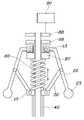
도 2는 본 발명의 일 실시예에 따른 차량용 자동 변속장치에서, 차량이 고속 주행할 시 차량용 자동 변속장치의 작동 모습을 도시한 도면이다.
도 3은 본 발명의 일실시예에 따른 차량용 자동 변속장치에서, 2단 변속기의 변속 맵을 도시한 도면이다.
도 4는 본 발명의 차량용 자동 변속장치에서, 제1실시예에 따른 탄성조절부의 모습을 상세히 도시한 도면이다.
도 5는 본 발명의 차량용 자동 변속장치에서, 제2실시예에 따른 탄성조절부의 모습을 상세히 도시한 도면이다.
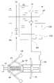
도 6은 본 발명의 차량용 자동 변속장치에서, 제3실시예에 따른 탄성조절부의 모습을 상세히 도시한 도면이다.
도 7은 본 발명의 일 실시예에 따른 차량용 자동 변속장치가 적용된 변속기 구조를 간단히 도시한 도면이다.1 is a diagram illustrating an operation of an automatic transmission for a vehicle according to an embodiment of the present invention when the vehicle is traveling at a low speed.
FIG. 2 is a diagram illustrating an operation of the automatic transmission for a vehicle according to an embodiment of the present invention when the vehicle is traveling at a high speed.
3 is a diagram showing a shift map of a two-speed transmission in an automatic transmission for a vehicle according to an embodiment of the present invention.
4 is a view showing in detail the appearance of the elastic adjustment unit according to the first embodiment in the automatic transmission device for a vehicle according to the present invention.
5 is a view showing in detail the appearance of the elastic adjustment unit according to the second embodiment in the automatic transmission for a vehicle according to the present invention.
FIG. 6 is a view showing in detail the appearance of the elastic adjustment unit according to the third embodiment in the automatic transmission device for a vehicle according to the present invention.
7 is a diagram simply showing a transmission structure to which an automatic transmission for a vehicle according to an embodiment of the present invention is applied.
이하에서는 첨부된 도면을 참조하여 본 발명의 바람직한 실시 예에 따른 차량용 자동 변속장치에 대하여 살펴본다.Hereinafter, an automatic transmission for a vehicle according to a preferred embodiment of the present invention will be described with reference to the accompanying drawings.
도 1은 본 발명의 일 실시예에 따른 차량용 자동 변속장치에서, 차량이 저속 주행할 시 차량용 자동 변속장치의 작동 모습을 도시한 도면이고, 도 2는 차량이 고속 주행할 시 차량용 자동 변속장치의 작동 모습을 도시한 도면이다.1 is a view showing the operation of the automatic transmission for a vehicle when the vehicle is traveling at a low speed in an automatic transmission for a vehicle according to an embodiment of the present invention, and FIG. 2 is a view of the automatic transmission for a vehicle when the vehicle is traveling at a high speed. This is a diagram showing how it works.
도 1 및 도 2를 참조하면, 본 발명에 따른 차량용 자동 변속장치는, 차량의 구동력에 의해 회전하는 회전축(10), 회전축(10) 상에 구비되며 회전축의 축방향을 따라 슬라이딩하도록 마련된 슬라이더부(40), 일단이 회전축에 힌지결합을 통해 연결되고, 회전축이 회전함에 따라 타단이 원심력에 의해 상승 또는 하강하는 제1연결부재(20), 일단이 제1연결부재(20) 상에 힌지결합되며, 타단이 슬라이더부(40)에 연결되어 제1연결부재(20)가 상승 또는 하강함에 따라 슬라이더부(40)가 상하 슬라이딩되도록 하는 제2연결부재(30), 슬라이더부(40)에 결합되며 슬라이더부(40)의 위치에 따라 회전축(10)의 축방향의 일측 또는 타측으로 변형되는 다이아프램 스프링(70), 슬라이더부(40) 또는 다이아프램 스프링(70)에 연결되며, 슬라이더부(40)의 위치에 따라 동기장치를 변속단 기어에 치합시키는 시프트포크(50), 다이아프램 스프링(70)의 탄성력을 조절하는 탄성 조절부(80) 및 차량의 속도에 따라 탄성 조절부(80)를 제어하여 다이아프램 스프링의 탄성력을 조절하는 제어부(90)를 포함할 수 있다.Referring to FIGS. 1 and 2 , the automatic transmission for a vehicle according to the present invention includes a
또한, 본 발명에 따른 차량용 자동 변속장치는, 회전축 상에 마련되며 제1연결부재의 일단이 힌지결합하는 제1링크부(13), 회전축 상에 마련되되 제1링크부의 하방에 마련되고 제2연결부재의 타단이 힌지결합되며 하면이 슬라이더부와 결합된 제2링크부(15), 및 회전축 상에 마련되며 제1링크부와 제2링크부 사이에 배치되고 탄성력을 가하도록 마련된 압축스프링(60)을 더 포함하여 구성될 수 있다.In addition, the automatic transmission for vehicles according to the present invention is provided on the rotating shaft and provided on the
즉, 본 발명에 따르면 차량이 이동함에 따라 회전축(10)이 회전하게 되고, 회전축(10)이 회전함에 따라 제1연결부재(20)는 원심력에 의해 원심추(23)가 상승 또는 하강하는 방향으로 힌지 회전하며, 이에 따라 슬라이더부(40)가 상측 또는 하측으로 슬라이딩하고, 슬라이더부(40)가 상측 또는 하측을 슬라이딩함에 따라 슬라이더부(40)에 결합되어 슬라이더부(40)의 위치에 따라 회전축의 축방향의 일측 또는 타측으로 변형되는 다이아프램 스프링(70)이 변형되고, 다이아프램 스프링(70)이 변형됨에 따라 다이아프램 스프링(70)에 연결된 시프트포크(50)가 상측 또는 하측으로 이동되면서 동기장치(SL)가 변속단 기어에 치합 또는 해제되어 차량의 변속이 이루어질 수 있다.That is, according to the present invention, the
구체적으로, 회전축(10)의 속도가 빨라지는 경우, 제1연결부재(20)는 상승하고, 이에 따라 슬라이더부(40)는 상측으로 슬라이딩하며, 슬라이더부(40)가 상측으로 슬라이딩함에 따라 다이아프램 스프링(70)은 회전축의 축방향의 일측으로 변형되고, 다이아프램 스프링(70)이 일측으로 변형됨에 따라 시프트포크(50)는 상측 방향으로 이동할 수 있다.Specifically, when the speed of the
반대로, 회전축(10)의 속도가 느려지는 경우, 제1연결부재(20)는 하강하고, 이에 따라 슬라이더부(40)는 하측으로 슬라이딩하며, 슬라이더부(40)가 하측으로 슬라이딩함에 따라 다이아프램 스프링(70)은 회전축의 축방향의 타측으로 변형되고, 다이아프램 스프링(70)이 타측으로 변형됨에 따라 시프트포크(50)는 하측으로 이동할 수 있다.Conversely, when the speed of the
이처럼, 본 발명에서는 차량 변속을 위해 다수의 동기장치들이 변속단 기어에 전자적인 제어를 통해 치합 또는 해제되도록 하는 전자적인 제어기를 구비하지 않고, 상술한 바와 같이 차속에 따른 기계적인 동작에 의해 다수의 동기장치들이 변속단 기어에 치합 또는 해제되도록 함으로써 자동으로 변속이 수행되도록 할 수 있다.As described above, the present invention does not include an electronic controller that engages or disengages a plurality of synchronizing devices to shift stage gears through electronic control for vehicle shifting. It is possible to automatically shift gears by engaging or disengaging the gears at the shift stage.
이하에서는 본 발명에 따른 차량용 자동 변속장치의 세부 구성에 대해 보다 상세히 설명하기로 한다.Hereinafter, the detailed configuration of the automatic transmission for a vehicle according to the present invention will be described in more detail.
회전축(10) 상에는 제1링크부(13)를 중심으로 힌지 회전하는 제1연결부재(20)가 마련되는데 제1연결부재(20)의 타단에는 회전축(10)이 회전함에 따라 발생하는 원심력을 극대화하기 위해 원심추(23)가 마련될 수 있다.On the rotating
제1연결부재(20)는 일단이 제1링크부(13)에 힌지결합되며, 회전축이 회전함에 따라 원심추가(23) 마련된 타단이 원심력에 의해 상승 또는 하강한다. 또한, 제1연결부재(20)의 중간부와 제2연결부재(30)의 일단은 힌지결합되고, 제2연결부재(30)의 타단이 제2링크부(15)와 힌지결합되는 바, 회전축(10)이 회전함에 따라 제1연결부재(20)가 상측 또는 하측으로 이동할 시, 제2연결부재(30)는 제1연결부재(20)를 따라 일단을 중심으로 힌지 회전할 수 있다.One end of the first connecting
슬라이더부(40)는 실시예에 따라, 회전축(10)을 감싸면서 축방향 이동이 가능한 다수의 링이 적용된 형상으로 마련될 수 있고, 단일의 원통 형상으로 마련될 수도 있다. 즉, 슬라이더부(40)의 형상은 설계자 또는 차량에 따라 다양하게 가변되어 설계될 수 있는바, 특정 형상으로 한정되어서는 안될 것이다.Depending on the embodiment, the
시프트포크(50)는 슬라이더부(40) 또는 다이아프램 스프링(70)에 연결될 수 있으며, 슬라이더부(40)의 위치에 따라 이동하여 동기장치(SL)를 변속단 기어에 치합 또는 해제시킬 수 있다. 이때, 시프트포크(50)는 다이아프램 스프링(70) 또는 슬라이더부(40)에 고정결합되어 일체로 슬라이딩되도록 마련될 수 있다. 아울러, 시프트포크(50)는 다이아프램 스프링(70)이 변형되는 시점에 동기장치(SL)가 변속단 기어에 치합 또는 해제되도록 마련될 수 있다. 슬라이더부(40)의 위치에 따라 시프트포크(50)가 동기장치(SL)를 변속단 기어에 치합 또는 해제시키는 것에 대해서는 추후 도 7을 참조하여 상세히 설명하기로 한다.The
압축스프링(60)은 회전축 상에 마련되며 제1링크부(13)와 제2링크부(15) 사이에 배치되어 탄성력을 가하도록 마련될 수 있다. 구체적으로 압축스프링(60)은 회전축(10)이 회전함에 따라 원심력에 의해 제1연결부재(20)의 타단이 상승 또는 하강할 시 압축 또는 이완될 수 있다.The
다이아프램 스프링(70)은 회전축(10) 상에 구비되고, 슬라이더부(40)에 결합되어 슬라이더부(40)의 슬라이딩 위치에 따라 회전축(10)의 축방향의 일측 또는 타측으로 변형될 수 있다. 여기서, 다이아프램 스프링(70)이 회전축(10)의 축방향의 일측 또는 타측으로 변형된다는 것은 다이아프램 스프링(70)이 가하는 탄성력의 방향이 전환되는 것을 의미할 수 있다.The
보다 구체적으로, 본 발명에서 다이아프램 스프링(70)은 기 설정된 변형량에 도달할 경우에 회전축의 축방향의 일측 또는 타측으로 변형되도록 마련될 수 있다. 즉, 다이아프램 스프링(70)에 하중이 가해지면 다이아프램 스프링(70)이 변형되기 시작하는데, 다이아프램 스프링(70)에 하중이 가해지면서 다이아프램 스프링(70)이 기 설정된 변형량에 도달하는 경우, 다이아프램 스프링(70)은 젖혀지면서 변형되게 될 수 있고, 이에 따라 다이아프램 스프링(70)이 가하는 탄성력의 방향이 전환될 수 있다.More specifically, in the present invention, the
즉, 차량의 속도가 상승하여 제1연결부재(20)에 작용하는 원심력에 의해 슬라이더부(40)가 상측으로 이동함에 따라 다이아프램 스프링(70)에 하중이 가해져 변형되기 시작하고, 기 설정된 변형량에 도달하면, 다이아프램 스프링(70)은 도 2에 도시된 바와 같이 변형되면서 탄성력을 가하는 방향이 전환될 수 있다. 아울러, 시프트포크(50)는 다이어프램 스프링(70)이 변형되는 시점에 동기장치의 슬리브가 변속단기어와 치합 또는 해제되기 시작하도록 마련됨으로써, 동기장치가 다이아프램 스프링(70)의 탄성력에 의해 변속단 기어에 보다 용이하게 치합 또는 해제되도록 할 수 있다. 여기서, 다이아프램 스프링(70)은 일단부가 슬라이더부(40)에 결합되고, 타단부는 회전축(10)과 함께 회전하되 축방향으로 이동되지 않도록 하기 위해 하우징 등과 같은 구성에 고정되도록 마련될 수 있다.That is, as the speed of the vehicle increases and the
탄성 조절부(80)는 다이아프램 스프링(70)의 탄성력을 조절하는 역할을 한다. 즉, 탄성 조절부(80)는 다이아프램 스프링(70)에 가해지는 하중을 조절하여 다이아프램 스프링(70)이 변형되는 변형량을 조절할 수 있다. 보다 구체적으로, 탄성조절부(80)는 압축스프링(60)을 압축 또는 이완시켜 슬라이더부(40)가 회전축(10)의 축방향을 따라 상하 슬라이딩되도록 하고, 슬라이더부(40)를 회전축(10)의 축방향을 따라 상하 슬라이딩시킴으로써 다이아프램 스프링(70)의 탄성력을 조절할 수 있다.The
도 3은 본 발명의 일실시예에 따른 차량용 자동 변속장치에서, 2단 변속기의 변속 맵을 도시한 도면이다. 도 3에 도시된 바와 같이 1단에서 2단으로 변속되는 차속은 일정하지 않을 수 있다. 즉, 차량이 특정 속도 이상으로 주행 중인 경우에만 1단에서 2단으로 변속되는 것이 아니라, 특정 속도 이하를 포함하여 다양한 차속의 범위에서도 1단에서 2단으로 변속될 수 있는데, 다양한 차속 범위에서 변속이 적절하게 이루어지도록 하기 위해 탄성 조절부(80)에서 다이아프램 스프링(70)의 탄성력을 조절할 수 있다.3 is a diagram showing a shift map of a two-speed transmission in an automatic transmission for a vehicle according to an embodiment of the present invention. As shown in FIG. 3 , a vehicle speed shifted from 1st gear to 2nd gear may not be constant. That is, the vehicle does not shift from 1st gear to 2nd gear only when the vehicle is driving at a certain speed or higher, but can shift from 1st gear to 2nd gear in a range of various vehicle speeds, including below a specific speed. In order to properly perform this, the elastic force of the
구체적으로, 본 발명에 따르면 차량이 주행함에 따라 회전축(10)이 회전하고, 회전축(10)이 회전함에 따라 제1연결부재(20)는 상승하면서 슬라이더부(40)를 상승시키며 다이아프램 스프링(70)에 하중을 가하여 다이아프램 스프링(70)을 변형시키고, 다이아프램 스프링(70)이 기 설정된 변형량에 도달하는 경우에 변속이 이루어질 수 있다. 즉, 변속이 이루어지기 위해서는 다이아프램 스프링(70)에 기 설정된 하중이 가해져 다이아프램 스프링(70)이 기 설정된 변형량에 도달해야 한다. 하지만, 차량이 고속으로 주행하는 경우에 다이아프램 스프링(70)에 가해지는 하중과 저속으로 주행하는 경우에 다이아프램 스프링(70)에 가해지는 하중이 다르기 때문에 다양한 차속 범위에서 변속이 적절히 이루어지도록 하기 위해 탄성 조절부(80)에서 다이아프램 스프링(70)의 탄성력을 조절하는 것이다.Specifically, according to the present invention, the rotating
보다 구체적인 예로, 다이아프램 스프링(70)에 10kg의 하중이 가해질 때 기 설정된 변형량에 도달하여 다이아프램 스프링(70)이 변형되어 변속이 이루어지고, 도 3에 도시된 바와 같이 변속 맵에 따라 차속이 Akm/h인 경우와 Bkm/h일 때 변속이 이루어지며, 차속이 Akm/h인 경우 다이아프램 스프링에 가해지는 하중이 5kg이고, Bkm/h인 경우 다이아프램 스프링에 가해지는 하중이 10kg인 경우를 생각해보자. 이와 같은 경우, 차속이 Akm/h인 경우 변속 맵에 따라 변속이 이루어져야 함에도 불구하고 다이아프램 스프링에 가해지는 하중이 5kg 이기 때문에 다이아프램 스프링이 기 설정된 변형량에 도달하지 못하여 변속이 이루어질 수 없게 되는데, 탄성 조절부(80)에서 차속에 따라 다이아프램 스프링의 탄성력을 조절함으로써, 변속 맵에 따라 다양한 차속에서 변속이 적절히 이루어지도록 할 수 있다. 즉, 차속이 Akm/h인 경우 탄성 조절부(80)에서는 다이아프램 스프링에 5kg의 하중이 미리 가해지도록 조절하여, Akm/h의 속도로 주행할 시 다이아프램 스프링이 기 설정된 변형량에 도달되도록 하여 변속이 이루어지게 할 수 있다.As a more specific example, when a load of 10 kg is applied to the
도 4는 본 발명의 차량용 자동 변속장치에서, 제1실시예에 따른 탄성조절부의 모습을 상세히 도시한 도면이고, 도 5는 제2실시예에 따른 탄성조절부의 모습을 상세히 도시한 도면이며, 도 6은 제3실시예에 따른 탄성조절부의 모습을 상세히 도시한 도면이다.Figure 4 is a view showing in detail the appearance of the elastic adjustment unit according to the first embodiment in the automatic transmission for a vehicle of the present invention, Figure 5 is a view showing in detail the appearance of the elasticity adjustment unit according to the second embodiment, 6 is a view showing in detail the appearance of the elastic adjusting unit according to the third embodiment.
도 4에 도시된 바와 같이, 탄성 조절부(80)는 모터(81), 회전축(10) 상에 마련되며 모터(10)와 연결된 캠기어(82), 회전축(10) 상에 마련되며 캠기어(82)와 일체로 구성된 베이스부(83) 및 회전축(10) 상에 마련되며 베이스부(83)와 압축스프링(60) 사이에 위치하고, 모터(81)가 회전함에 따라 상하로 이동하여 압축스프링(60)을 압축 또는 이완시키는 압축스프링 위치 조절부(84)를 포함하여 구성될 수 있다.As shown in FIG. 4, the
이와 같은 경우, 실시예에 따라 모터(81)를 반시계 방향으로 회전하여 모터기어를 회전시키면, 모터기어는 캠기어(82)를 회전시키고, 캠기어(82)는 캠기어(82)와 일체로 구성된 압축스프링 위치 조절부(84)를 회전시킨다. 이때, 압축스프링 위치 조절부(84) 상방에 위치한 베이스부(83)가 압축스프링 위치 조절부(84)를 하방으로 밀어 압축스프링(60)을 압축시키고, 압축스프링(60)이 압축됨에 따라 슬라이더부(40)는 하측으로 슬라이딩되어 슬라이더부(40)에 결합된 다이아프램 스프링(70)에 하중을 가하여 다이아프램 스프링(70)의 탄성력을 조절할 수 있다. 만약, 모터(81)를 시계방향으로 회전하게 되면 상술한 방식의 역으로 다이아프램 스프링(70)의 탄성력을 조절할 수 있다.In this case, when the motor gear is rotated by rotating the
또한, 도 5에 도시된 바와 같이, 탄성 조절부(80)는 압축스프링(60) 상방에 위치하는 실린더(85), 실린더(85)에 압력을 제공하는 압력제공부(86), 및 실린더 내부에 위치하며 압축스프링 상방에 위치하고, 실린더에 압력이 제공됨에 따라 상하로 이동하여 압축스프링을 압축 또는 이완시키는 피스톤(87)을 포함하여 구성될 수 있다. 이와 같은 경우, 압력제공부에서 실린더에 압력을 제공하여 피스톤을 하측으로 이동하여 압축스프링을 압축시키고, 압축스프링이 압축됨에 따라 슬라이더부는 하측으로 슬라이딩되어 슬라이더부에 결합된 다이아프램 스프링에 하중을 가하여 다이아프램 스프링의 탄성력을 조절할 수 있다. 여기서, 압력제공부에서 압력을 제공하는 방식은 공압 또는 유압일 수 있다.In addition, as shown in FIG. 5, the
더 나아가, 도 6에 도시된 바와 같이, 탄성 조절부(80)는, 서로 같은 극이며 이격되어 상하에 위치하는 한 쌍의 자기체(88) 및 하방에 위치한 자기체의 하면과 결합되며 압축스프링 상방에 위치하고 자석의 자력이 변화됨에 따라 상하로 이동하여 압축스프링을 압축 또는 이완시키는 피스톤(87)을 포함하여 구성될 수 있다. 이와 같은 경우, 한 쌍의 자기체의 자기력의 세기를 변화시킴에 따라 하방에 위치한 자기체를 하측으로 이동시켜 압축스프링을 압축시키고, 압축스프링이 압축됨에 따라 슬라이더부는 하측으로 슬라이딩되어 슬라이더부에 결합된 다이아프램 스프링에 하중을 가하여 다이아프램 스프링의 탄성력을 조절할 수 있다.Furthermore, as shown in FIG. 6, the
제어부(90)는 차량의 속도에 따라 탄성 조절부(80)를 제어하여 압축스프링(60)을 압축 또는 이완시켜 슬라이더부(40)를 회전축의 축방향을 따라 상하 슬라이딩시키고, 슬라이더부(40)를 회전축의 축방향을 따라 상하 슬라이딩시킴으로써 다이아프램 스프링(70)의 탄성력을 조절하여 다양한 차속의 범위에서 적절하게 변속이 이루어지도록 할 수 있다.The
도 7은 본 발명의 일 실시예에 따른 차량용 자동 변속장치가 적용된 변속기 구조를 간단히 도시한 도면이다. 도 7을 참조하면, 본 발명의 차량용 자동 변속장치는 DCT(Dual Clutch Transmission) 차량에 적용될 수 있으며, 앞서 설명한 바와 같이, 차량이 이동함에 따라 회전축(10)이 회전하게 되고, 회전축(10)이 회전함에 따라 제1연결부재(20)는 원심력에 의해 원심추(23)가 상승 또는 하강하는 방향으로 힌지 회전하며, 이에 따라 슬라이더부(40)가 상측 또는 하측으로 슬라이딩하고, 슬라이더부(40)가 상측 또는 하측을 슬라이딩함에 따라 슬라이더부(40)에 결합되어 슬라이더부(40)의 위치에 따라 회전축의 축방향의 일측 또는 타측으로 변형되는 다이아프램 스프링(70)이 변형되고, 다이아프램 스프링(70)이 변형됨에 따라 슬라이더부(40)에 연결된 시프트포크(50)가 상측 또는 하측으로 이동되면서 동기장치(SL)가 변속단 기어에 치합 또는 해제되도록 하여 차량의 변속이 이루어질 수 있다.7 is a diagram simply showing a transmission structure to which an automatic transmission for a vehicle according to an embodiment of the present invention is applied. Referring to FIG. 7 , the automatic transmission for a vehicle of the present invention can be applied to a DCT (Dual Clutch Transmission) vehicle, and as described above, the rotating
이상 설명한 바와 같이, 본 발명에 따르면 차량 변속을 위해 다수의 동기장치들이 변속단 기어에 전자적인 제어를 통해 치합 또는 해제되도록 하는 전자적인 제어기를 구비하지 않고, 차속에 따른 기계적인 동작에 의해 다수의 동기장치들이 변속단 기어에 치합 또는 해제되도록 함으로써 자동으로 변속이 수행되도록 할 수 있다.As described above, according to the present invention, a plurality of synchronizing devices are not provided with an electronic controller that engages or disengages the shift stage gear through electronic control for vehicle shift, and mechanically operates according to the vehicle speed. It is possible to automatically shift gears by engaging or disengaging the gears at the shift stage.
또한, 본 발명에 따르면, 제어부에서 차량의 속도에 따라 탄성 조절부를 제어하여 압축스프링을 압축 또는 이완시켜 슬라이더부를 회전축의 축방향을 따라 상하 슬라이딩시키고, 슬라이더부를 회전축의 축방향을 따라 상하 슬라이딩시켜 다이아프램 스프링의 탄성력을 조절함으로써 다양한 차속의 범위에서 적절하게 변속이 이루어지도록 할 수 있다.In addition, according to the present invention, the control unit controls the elastic adjustment unit according to the speed of the vehicle to compress or relax the compression spring so that the slider unit slides up and down along the axial direction of the rotation shaft, and slides the slider unit up and down along the axial direction of the rotation shaft. By adjusting the elastic force of the spram spring, it is possible to properly shift gears in various vehicle speed ranges.
본 발명은 특정한 실시예에 관련하여 도시하고 설명하였지만, 이하의 특허청구범위에 의해 제공되는 본 발명의 기술적 사상을 벗어나지 않는 한도 내에서, 본 발명이 다양하게 개량 및 변화될 수 있다는 것은 당 업계에서 통상의 지식을 가진 자에게 있어서 자명할 것이다.Although the present invention has been shown and described in relation to specific embodiments, it is known in the art that the present invention can be variously improved and changed without departing from the technical spirit of the present invention provided by the claims below. It will be self-evident to those skilled in the art.
10: 회전축13: 제1링크부
15: 제2링크부20: 제1연결부재
23: 원심추30: 제2연결부재
40: 슬라이더부50: 시프트포크
60: 압축스프링70: 다이아프램 스프링
80: 탄성 조절부81: 모터
82: 캠기어: 83: 베이스부
84: 압축스프링 위치 조절부85: 실린더
86: 압력제공부87: 피스톤
88: 자기체90: 제어부10: axis of rotation 13: first link
15: second link unit 20: first connecting member
23: centrifugal weight 30: second connecting member
40: slider part 50: shift fork
60: compression spring 70: diaphragm spring
80: elastic control unit 81: motor
82: cam gear: 83: base part
84: compression spring position control unit 85: cylinder
86: pressure supply unit 87: piston
88: magnetic body 90: control unit
Claims (9)
Translated fromKorean회전축 상에 구비되며 회전축의 축방향을 따라 슬라이딩하도록 마련된 슬라이더부;
일단이 회전축에 힌지결합을 통해 연결되고, 회전축이 회전함에 따라 타단이 원심력에 의해 상승 또는 하강하는 제1연결부재;
일단이 제1연결부재 상에 힌지결합되며, 타단이 슬라이더부에 연결되어 제1연결부재가 상승 또는 하강함에 따라 슬라이더부가 상하 슬라이딩되도록 하는 제2연결부재;
슬라이더부에 결합되며 슬라이더부의 위치에 따라 회전축의 축방향의 일측 또는 타측으로 변형되는 다이아프램 스프링;
슬라이더부 또는 다이아프램 스프링에 연결되며, 슬라이더부의 위치에 따라 동기장치를 변속단 기어에 치합시키는 시프트포크;
다이아프램 스프링의 탄성력을 조절하는 탄성 조절부; 및
차량의 속도에 따라 탄성 조절부를 제어하여 다이아프램 스프링의 탄성력을 조절하는 제어부;를 포함하고,
다이아프램 스프링은 슬라이더부의 위치에 따라 하중이 가해져 기 설정된 변형량에 도달할 경우에 회전축 축방향의 일측 또는 타측으로 변형되어 탄성력의 방향이 전환되고;
시프트포크는 다이아프램 스프링이 변형되는 시점에 동기장치가 변속단기어에 치합 또는 해제되기 시작하도록 구성함으로써, 다이아프램 스프링의 탄성력에 의해 동기장치가 변속단기어에 치합 또는 해제되는 것을 특징으로 하는 차량용 자동 변속장치.A rotational shaft rotated by the driving force of the vehicle;
a slider provided on the rotating shaft and provided to slide along the axial direction of the rotating shaft;
a first connecting member having one end connected to the rotating shaft through a hinge coupling and the other end rising or falling by centrifugal force as the rotating shaft rotates;
a second linking member having one end hinged on the first linking member and the other end connected to the slider so that the slider slides up and down as the first linking member rises or falls;
a diaphragm spring coupled to the slider unit and deformed to one side or the other side in the axial direction of the rotating shaft according to the position of the slider unit;
a shift fork connected to the slider part or the diaphragm spring and engaging the synchronizing device with the shift stage gear according to the position of the slider part;
Elasticity control unit for adjusting the elastic force of the diaphragm spring; and
A control unit controlling the elastic force of the diaphragm spring by controlling the elastic adjusting unit according to the speed of the vehicle;
The diaphragm spring is deformed to one side or the other side in the axial direction of the rotating shaft when a load is applied according to the position of the slider unit and reaches a predetermined amount of deformation, and the direction of the elastic force is changed;
The shift fork is configured such that the synchronizing device starts to engage or disengage from the gearshift gear at the time the diaphragm spring is deformed, so that the synchronizer engages with or disengages from the gearshift gear due to the elastic force of the diaphragm spring. automatic gearbox.
회전축 상에 마련되며 제1연결부재의 일단이 힌지결합하는 제1링크부;
회전축 상에 마련되되 제1링크부의 하방에 마련되고 제2연결부재의 타단이 힌지결합되며 하면이 슬라이더부와 결합된 제2링크부; 및
회전축 상에 마련되며 제1링크부와 제2링크부 사이에 배치되고 탄성력을 가하도록 마련된 압축스프링;을 더 포함하는 차량용 자동 변속장치.The method of claim 1,
A first link portion provided on a rotating shaft and having one end of the first connecting member hinged;
A second link part provided on the rotating shaft, provided below the first link part, the other end of the second connecting member is hinged, and the lower surface is coupled to the slider part; and
An automatic transmission for a vehicle further comprising a compression spring provided on a rotating shaft and disposed between the first link unit and the second link unit and provided to apply an elastic force.
탄성 조절부는 압축스프링을 압축 또는 이완시켜 슬라이더부가 회전축의 축방향을 따라 상하 슬라이딩 되도록 하고, 슬라이더부를 회전축의 축방향을 따라 상하 슬라이딩시킴으로써 다이아프램 스프링의 탄성력을 조절하는 것을 특징으로 하는 차량용 자동 변속장치.The method of claim 2,
The elastic control unit compresses or relaxes the compression spring so that the slider part slides up and down along the axial direction of the rotation shaft, and adjusts the elastic force of the diaphragm spring by sliding the slider part up and down along the axial direction of the rotation shaft. .
제어부는 차량의 속도에 따라 탄성 조절부를 제어하여 압축스프링을 압축 또는 이완시켜 슬라이더부를 회전축의 축방향을 따라 상하 슬라이딩시키고, 슬라이더부를 회전축의 축방향을 따라 상하 슬라이딩시킴으로써 다이아프램 스프링의 탄성력을 조절하는 것을 특징으로 하는 차량용 자동 변속장치.The method of claim 3,
The control unit controls the elastic adjustment unit according to the speed of the vehicle to compress or relax the compression spring to slide the slider unit up and down along the axial direction of the rotation shaft, and to slide the slider unit up and down along the axial direction of the rotation shaft to adjust the elastic force of the diaphragm spring. An automatic transmission for a vehicle, characterized in that.
모터;
회전축 상에 마련되며 모터와 연결된 캠기어;
회전축 상에 마련되며 캠기어와 일체로 구성된 베이스부; 및
회전축 상에 마련되며 베이스부과 압축스프링 사이에 위치하고, 모터가 회전함에 따라 상하로 이동하여 압축스프링을 압축 또는 이완시키는 압축스프링 위치 조절부;를 포함하여 구성되는 것을 특징으로 하는 차량용 자동 변속장치.The method according to claim 2, the elastic control unit,
motor;
A cam gear provided on a rotating shaft and connected to the motor;
a base portion provided on a rotating shaft and integrally formed with a cam gear; and
An automatic transmission for a vehicle, characterized in that it is configured to include; a compression spring position adjusting unit provided on a rotating shaft and located between the base portion and the compression spring and moving up and down as the motor rotates to compress or relax the compression spring.
압축스프링 상방에 위치하는 실린더;
실린더에 압력을 제공하는 압력제공부; 및
실린더 내부에 위치하며 압축스프링 상방에 위치하고, 실린더에 압력이 제공됨에 따라 상하로 이동하여 압축스프링을 압축 또는 이완시키는 피스톤;을 포함하여 구성되는 것을 특징으로 하는 차량용 자동 변속장치.The method according to claim 2, the elastic control unit,
Cylinder located above the compression spring;
a pressure providing unit providing pressure to the cylinder; and
An automatic transmission for a vehicle, characterized in that it is configured to include; a piston located inside the cylinder and located above the compression spring and moving up and down as pressure is provided to the cylinder to compress or relax the compression spring.
서로 같은 극이며, 이격되어 상하에 위치하는 한쌍의 자기체; 및
하방에 위치한 자기체의 하면과 결합되며 압축스프링 상방에 위치하고 자기체의 자력이 변화됨에 따라 상하로 이동하여 압축스프링을 압축 또는 이완시키는 피스톤;을 포함하여 구성되는 것을 특징으로 하는 차량용 자동 변속장치.The method according to claim 2, the elastic control unit
A pair of magnetic bodies having the same poles and spaced apart from each other; and
An automatic transmission for a vehicle, characterized in that it is configured to include; a piston coupled to the lower surface of the magnetic body located below and located above the compression spring and moving up and down as the magnetic force of the magnetic body changes, compressing or relaxing the compression spring.
시프트포크는 다이아프램 스프링 또는 슬라이더부에 고정결합되어 일체로 슬라이딩되도록 마련된 것을 특징으로 하는 차량용 자동 변속장치.The method of claim 1,
The shift fork is an automatic transmission for a vehicle, characterized in that it is provided to slide integrally by being fixedly coupled to the diaphragm spring or slider.
Priority Applications (3)
| Application Number | Priority Date | Filing Date | Title |
|---|---|---|---|
| KR1020170160103AKR102465904B1 (en) | 2017-11-28 | 2017-11-28 | Automatic transmission for vehicle |
| US15/978,534US11137067B2 (en) | 2017-11-28 | 2018-05-14 | Automatic transmission for vehicle |
| CN201810557912.7ACN109838553B (en) | 2017-11-28 | 2018-06-01 | Automatic transmission for vehicle |
Applications Claiming Priority (1)
| Application Number | Priority Date | Filing Date | Title |
|---|---|---|---|
| KR1020170160103AKR102465904B1 (en) | 2017-11-28 | 2017-11-28 | Automatic transmission for vehicle |
Publications (2)
| Publication Number | Publication Date |
|---|---|
| KR20190061576A KR20190061576A (en) | 2019-06-05 |
| KR102465904B1true KR102465904B1 (en) | 2022-11-11 |
Family
ID=66634976
Family Applications (1)
| Application Number | Title | Priority Date | Filing Date |
|---|---|---|---|
| KR1020170160103AActiveKR102465904B1 (en) | 2017-11-28 | 2017-11-28 | Automatic transmission for vehicle |
Country Status (3)
| Country | Link |
|---|---|
| US (1) | US11137067B2 (en) |
| KR (1) | KR102465904B1 (en) |
| CN (1) | CN109838553B (en) |
Families Citing this family (5)
| Publication number | Priority date | Publication date | Assignee | Title |
|---|---|---|---|---|
| DE102017208633A1 (en)* | 2017-05-22 | 2018-11-22 | Audi Ag | Axle drive device for a motor vehicle and method for operating an axle drive device |
| KR102465903B1 (en)* | 2017-11-27 | 2022-11-11 | 현대자동차주식회사 | Automatic transmission for vehicle |
| KR102465904B1 (en) | 2017-11-28 | 2022-11-11 | 현대자동차주식회사 | Automatic transmission for vehicle |
| CN111847108A (en)* | 2020-07-21 | 2020-10-30 | 湖州益浩毛纺原料有限公司 | Constant-speed spinning take-up roller fixing device based on circular linear velocity law |
| CN112973222B (en)* | 2021-03-01 | 2021-11-09 | 刘红霞 | Building wastewater recycling device |
Citations (2)
| Publication number | Priority date | Publication date | Assignee | Title |
|---|---|---|---|---|
| CN201575118U (en)* | 2009-11-19 | 2010-09-08 | 钟志豪 | Stepless transmission speed change mechanism |
| KR101048358B1 (en)* | 2010-12-28 | 2011-07-14 | 오문근 | Mechanical automatic transmission |
Family Cites Families (25)
| Publication number | Priority date | Publication date | Assignee | Title |
|---|---|---|---|---|
| US1686827A (en)* | 1923-03-22 | 1928-10-09 | Gustav C Maag | Automatic coupling device for transmission of power |
| US2189748A (en) | 1936-11-07 | 1940-02-06 | Wilson Harvey | Automatic door lock |
| US2386217A (en)* | 1939-07-28 | 1945-10-09 | Kegresse Adolphe | Automatic variable speed transmission |
| US2654261A (en)* | 1949-06-11 | 1953-10-06 | Borg Warner | Double countershaft transmission |
| US2730909A (en)* | 1951-09-01 | 1956-01-17 | Edward F Svoboda | Manual control for automatic transmissions |
| AT381368B (en)* | 1979-10-16 | 1986-10-10 | Friedmann & Maier Ag | CONTROL SYSTEM FOR INTERNAL COMBUSTION ENGINES |
| FR2545883B1 (en) | 1983-05-09 | 1985-08-16 | Roffidal Rene | PRESSURE LIQUID MOTOR FOR CONTROLLING A MACHINE CONSUMING SUCH LIQUID |
| JPS60170225U (en)* | 1984-04-16 | 1985-11-12 | 川崎重工業株式会社 | Vehicle speed governor |
| FR2605959B1 (en) | 1986-10-31 | 1992-01-17 | Bendix France | BRAKING DEVICE FOR VEHICLE |
| SU1796791A1 (en)* | 1990-10-30 | 1993-02-23 | Sergej B Bogachev | Clutch |
| JPH07180722A (en)* | 1993-12-24 | 1995-07-18 | Brother Ind Ltd | Automatic bearing preload adjusting device |
| JPH07280078A (en)* | 1994-03-31 | 1995-10-27 | Samsung Heavy Ind Co Ltd | Automatic speed change gear utilizing centrifugal force |
| JPH10213221A (en)* | 1997-01-28 | 1998-08-11 | Suzuki Motor Corp | Shift operating device |
| DE19815257A1 (en) | 1997-04-18 | 1998-10-22 | Atlas Fahrzeugtechnik Gmbh | Actuator for automating transmission |
| JP3674253B2 (en)* | 1997-08-12 | 2005-07-20 | トヨタ自動車株式会社 | Gearbox with synchronizer |
| US5989149A (en)* | 1998-04-01 | 1999-11-23 | Apostolo; Mauricio C. | Automatic friction wheel transmission |
| KR100580845B1 (en) | 2004-05-25 | 2006-05-17 | 현대자동차주식회사 | Clutch for Manual Transmission |
| KR101134878B1 (en)* | 2005-12-13 | 2012-04-13 | 현대자동차주식회사 | Apparatus For Variable Valve Timing For Vehicle |
| CN201265487Y (en)* | 2008-05-29 | 2009-07-01 | 青岛安华新能源开发有限公司 | Flying bar synchronous variable-pitch mechanism |
| JP5909135B2 (en) | 2012-03-30 | 2016-04-26 | 富士重工業株式会社 | transmission |
| KR20150077732A (en) | 2013-12-30 | 2015-07-08 | 현대다이모스(주) | Hybrid transmission and control method thereof |
| CN106763541A (en)* | 2016-11-29 | 2017-05-31 | 杭州市萧山区高级技工学校 | A kind of automatic speed changer for machine based on centrifugal force controlled |
| KR102399477B1 (en)* | 2017-07-28 | 2022-05-18 | 현대자동차주식회사 | Apparatus for auto shifting of vehicle |
| KR102465903B1 (en)* | 2017-11-27 | 2022-11-11 | 현대자동차주식회사 | Automatic transmission for vehicle |
| KR102465904B1 (en) | 2017-11-28 | 2022-11-11 | 현대자동차주식회사 | Automatic transmission for vehicle |
- 2017
- 2017-11-28KRKR1020170160103Apatent/KR102465904B1/enactiveActive
- 2018
- 2018-05-14USUS15/978,534patent/US11137067B2/enactiveActive
- 2018-06-01CNCN201810557912.7Apatent/CN109838553B/ennot_activeExpired - Fee Related
Patent Citations (2)
| Publication number | Priority date | Publication date | Assignee | Title |
|---|---|---|---|---|
| CN201575118U (en)* | 2009-11-19 | 2010-09-08 | 钟志豪 | Stepless transmission speed change mechanism |
| KR101048358B1 (en)* | 2010-12-28 | 2011-07-14 | 오문근 | Mechanical automatic transmission |
Also Published As
| Publication number | Publication date |
|---|---|
| KR20190061576A (en) | 2019-06-05 |
| CN109838553A (en) | 2019-06-04 |
| CN109838553B (en) | 2021-09-28 |
| US11137067B2 (en) | 2021-10-05 |
| US20190162299A1 (en) | 2019-05-30 |
Similar Documents
| Publication | Publication Date | Title |
|---|---|---|
| KR102465904B1 (en) | Automatic transmission for vehicle | |
| CN106438872B (en) | Transmission for electric vehicle | |
| KR102399477B1 (en) | Apparatus for auto shifting of vehicle | |
| US10533639B2 (en) | Automatic transmission | |
| CN104019193B (en) | Moment of torsion back difference mode two-shift automatic speed variator and shift control method | |
| US7983825B2 (en) | Method and transmission arrangement for changing gears | |
| EP2055556A3 (en) | Control of engine torque during upshift and downshift torque phase for a hybrid powertrain system | |
| CN104482139B (en) | Planetary-drive two-gear automatic transmission | |
| GB2348630A (en) | Drive train | |
| CA2639535A1 (en) | Gear ratio control method for continuously variable transmission | |
| KR102465903B1 (en) | Automatic transmission for vehicle | |
| CN103307219B (en) | A kind of electric vehicle two grades of automatic mechanical transmissions | |
| CN102016360B (en) | Shift control method in automated manual transmission | |
| CN103307222B (en) | A kind of automotive dynamoelectric machine formula automatic transmission with free wheel device | |
| US8771146B2 (en) | Method of controlling transmission of vehicle | |
| JP2007113608A (en) | Shift control device | |
| US8758196B2 (en) | Method of controlling transmission of vehicle | |
| US9004252B2 (en) | Transmission shifting element decelerator | |
| US10746263B2 (en) | Automatic transmission with electric synchronization | |
| CN105299154B (en) | Differential combination gear continuously variable transmission | |
| Goszczak et al. | Test stand for modelling hydraulically controlled continuously variable transmission | |
| CN111207209B (en) | Gear shifting control system, gear shifting control method and vehicle | |
| WO2016095030A1 (en) | Mechanical control of a toroidal continuously variable transmission (cvt) | |
| JPH0587224A (en) | Shift control method of mechanical automatic transmission | |
| KR20190025143A (en) | Automatic transmission for vehicle |
Legal Events
| Date | Code | Title | Description |
|---|---|---|---|
| PA0109 | Patent application | Patent event code:PA01091R01D Comment text:Patent Application Patent event date:20171128 | |
| PG1501 | Laying open of application | ||
| A201 | Request for examination | ||
| PA0201 | Request for examination | Patent event code:PA02012R01D Patent event date:20201109 Comment text:Request for Examination of Application Patent event code:PA02011R01I Patent event date:20171128 Comment text:Patent Application | |
| E902 | Notification of reason for refusal | ||
| PE0902 | Notice of grounds for rejection | Comment text:Notification of reason for refusal Patent event date:20220513 Patent event code:PE09021S01D | |
| E701 | Decision to grant or registration of patent right | ||
| PE0701 | Decision of registration | Patent event code:PE07011S01D Comment text:Decision to Grant Registration Patent event date:20220805 | |
| GRNT | Written decision to grant | ||
| PR0701 | Registration of establishment | Comment text:Registration of Establishment Patent event date:20221107 Patent event code:PR07011E01D | |
| PR1002 | Payment of registration fee | Payment date:20221108 End annual number:3 Start annual number:1 | |
| PG1601 | Publication of registration |