KR102464886B1 - Percutaneous implantable nuclear prosthesis - Google Patents
Percutaneous implantable nuclear prosthesisDownload PDFInfo
- Publication number
- KR102464886B1 KR102464886B1KR1020177014497AKR20177014497AKR102464886B1KR 102464886 B1KR102464886 B1KR 102464886B1KR 1020177014497 AKR1020177014497 AKR 1020177014497AKR 20177014497 AKR20177014497 AKR 20177014497AKR 102464886 B1KR102464886 B1KR 102464886B1
- Authority
- KR
- South Korea
- Prior art keywords
- inflatable enclosure
- opening
- section
- valve
- membrane
- Prior art date
- Legal status (The legal status is an assumption and is not a legal conclusion. Google has not performed a legal analysis and makes no representation as to the accuracy of the status listed.)
- Active
Links
Images


Classifications
- A—HUMAN NECESSITIES
- A61—MEDICAL OR VETERINARY SCIENCE; HYGIENE
- A61F—FILTERS IMPLANTABLE INTO BLOOD VESSELS; PROSTHESES; DEVICES PROVIDING PATENCY TO, OR PREVENTING COLLAPSING OF, TUBULAR STRUCTURES OF THE BODY, e.g. STENTS; ORTHOPAEDIC, NURSING OR CONTRACEPTIVE DEVICES; FOMENTATION; TREATMENT OR PROTECTION OF EYES OR EARS; BANDAGES, DRESSINGS OR ABSORBENT PADS; FIRST-AID KITS
- A61F2/00—Filters implantable into blood vessels; Prostheses, i.e. artificial substitutes or replacements for parts of the body; Appliances for connecting them with the body; Devices providing patency to, or preventing collapsing of, tubular structures of the body, e.g. stents
- A61F2/02—Prostheses implantable into the body
- A61F2/30—Joints
- A61F2/44—Joints for the spine, e.g. vertebrae, spinal discs
- A61F2/441—Joints for the spine, e.g. vertebrae, spinal discs made of inflatable pockets or chambers filled with fluid, e.g. with hydrogel
- A—HUMAN NECESSITIES
- A61—MEDICAL OR VETERINARY SCIENCE; HYGIENE
- A61F—FILTERS IMPLANTABLE INTO BLOOD VESSELS; PROSTHESES; DEVICES PROVIDING PATENCY TO, OR PREVENTING COLLAPSING OF, TUBULAR STRUCTURES OF THE BODY, e.g. STENTS; ORTHOPAEDIC, NURSING OR CONTRACEPTIVE DEVICES; FOMENTATION; TREATMENT OR PROTECTION OF EYES OR EARS; BANDAGES, DRESSINGS OR ABSORBENT PADS; FIRST-AID KITS
- A61F2/00—Filters implantable into blood vessels; Prostheses, i.e. artificial substitutes or replacements for parts of the body; Appliances for connecting them with the body; Devices providing patency to, or preventing collapsing of, tubular structures of the body, e.g. stents
- A61F2/02—Prostheses implantable into the body
- A61F2/30—Joints
- A61F2/3094—Designing or manufacturing processes
- A—HUMAN NECESSITIES
- A61—MEDICAL OR VETERINARY SCIENCE; HYGIENE
- A61F—FILTERS IMPLANTABLE INTO BLOOD VESSELS; PROSTHESES; DEVICES PROVIDING PATENCY TO, OR PREVENTING COLLAPSING OF, TUBULAR STRUCTURES OF THE BODY, e.g. STENTS; ORTHOPAEDIC, NURSING OR CONTRACEPTIVE DEVICES; FOMENTATION; TREATMENT OR PROTECTION OF EYES OR EARS; BANDAGES, DRESSINGS OR ABSORBENT PADS; FIRST-AID KITS
- A61F2/00—Filters implantable into blood vessels; Prostheses, i.e. artificial substitutes or replacements for parts of the body; Appliances for connecting them with the body; Devices providing patency to, or preventing collapsing of, tubular structures of the body, e.g. stents
- A61F2/02—Prostheses implantable into the body
- A61F2/30—Joints
- A61F2/44—Joints for the spine, e.g. vertebrae, spinal discs
- A61F2/442—Intervertebral or spinal discs, e.g. resilient
- B—PERFORMING OPERATIONS; TRANSPORTING
- B29—WORKING OF PLASTICS; WORKING OF SUBSTANCES IN A PLASTIC STATE IN GENERAL
- B29C—SHAPING OR JOINING OF PLASTICS; SHAPING OF MATERIAL IN A PLASTIC STATE, NOT OTHERWISE PROVIDED FOR; AFTER-TREATMENT OF THE SHAPED PRODUCTS, e.g. REPAIRING
- B29C41/00—Shaping by coating a mould, core or other substrate, i.e. by depositing material and stripping-off the shaped article; Apparatus therefor
- B29C41/02—Shaping by coating a mould, core or other substrate, i.e. by depositing material and stripping-off the shaped article; Apparatus therefor for making articles of definite length, i.e. discrete articles
- B29C41/14—Dipping a core
- B—PERFORMING OPERATIONS; TRANSPORTING
- B29—WORKING OF PLASTICS; WORKING OF SUBSTANCES IN A PLASTIC STATE IN GENERAL
- B29C—SHAPING OR JOINING OF PLASTICS; SHAPING OF MATERIAL IN A PLASTIC STATE, NOT OTHERWISE PROVIDED FOR; AFTER-TREATMENT OF THE SHAPED PRODUCTS, e.g. REPAIRING
- B29C45/00—Injection moulding, i.e. forcing the required volume of moulding material through a nozzle into a closed mould; Apparatus therefor
- B29C45/14—Injection moulding, i.e. forcing the required volume of moulding material through a nozzle into a closed mould; Apparatus therefor incorporating preformed parts or layers, e.g. injection moulding around inserts or for coating articles
- A—HUMAN NECESSITIES
- A61—MEDICAL OR VETERINARY SCIENCE; HYGIENE
- A61F—FILTERS IMPLANTABLE INTO BLOOD VESSELS; PROSTHESES; DEVICES PROVIDING PATENCY TO, OR PREVENTING COLLAPSING OF, TUBULAR STRUCTURES OF THE BODY, e.g. STENTS; ORTHOPAEDIC, NURSING OR CONTRACEPTIVE DEVICES; FOMENTATION; TREATMENT OR PROTECTION OF EYES OR EARS; BANDAGES, DRESSINGS OR ABSORBENT PADS; FIRST-AID KITS
- A61F2/00—Filters implantable into blood vessels; Prostheses, i.e. artificial substitutes or replacements for parts of the body; Appliances for connecting them with the body; Devices providing patency to, or preventing collapsing of, tubular structures of the body, e.g. stents
- A61F2/02—Prostheses implantable into the body
- A61F2/30—Joints
- A61F2002/30001—Additional features of subject-matter classified in A61F2/28, A61F2/30 and subgroups thereof
- A61F2002/30003—Material related properties of the prosthesis or of a coating on the prosthesis
- A61F2002/3006—Properties of materials and coating materials
- A61F2002/30092—Properties of materials and coating materials using shape memory or superelastic materials, e.g. nitinol
- A—HUMAN NECESSITIES
- A61—MEDICAL OR VETERINARY SCIENCE; HYGIENE
- A61F—FILTERS IMPLANTABLE INTO BLOOD VESSELS; PROSTHESES; DEVICES PROVIDING PATENCY TO, OR PREVENTING COLLAPSING OF, TUBULAR STRUCTURES OF THE BODY, e.g. STENTS; ORTHOPAEDIC, NURSING OR CONTRACEPTIVE DEVICES; FOMENTATION; TREATMENT OR PROTECTION OF EYES OR EARS; BANDAGES, DRESSINGS OR ABSORBENT PADS; FIRST-AID KITS
- A61F2/00—Filters implantable into blood vessels; Prostheses, i.e. artificial substitutes or replacements for parts of the body; Appliances for connecting them with the body; Devices providing patency to, or preventing collapsing of, tubular structures of the body, e.g. stents
- A61F2/02—Prostheses implantable into the body
- A61F2/30—Joints
- A61F2002/30001—Additional features of subject-matter classified in A61F2/28, A61F2/30 and subgroups thereof
- A61F2002/30108—Shapes
- A61F2002/30199—Three-dimensional shapes
- A61F2002/30224—Three-dimensional shapes cylindrical
- A61F2002/30235—Three-dimensional shapes cylindrical tubular, e.g. sleeves
- A—HUMAN NECESSITIES
- A61—MEDICAL OR VETERINARY SCIENCE; HYGIENE
- A61F—FILTERS IMPLANTABLE INTO BLOOD VESSELS; PROSTHESES; DEVICES PROVIDING PATENCY TO, OR PREVENTING COLLAPSING OF, TUBULAR STRUCTURES OF THE BODY, e.g. STENTS; ORTHOPAEDIC, NURSING OR CONTRACEPTIVE DEVICES; FOMENTATION; TREATMENT OR PROTECTION OF EYES OR EARS; BANDAGES, DRESSINGS OR ABSORBENT PADS; FIRST-AID KITS
- A61F2/00—Filters implantable into blood vessels; Prostheses, i.e. artificial substitutes or replacements for parts of the body; Appliances for connecting them with the body; Devices providing patency to, or preventing collapsing of, tubular structures of the body, e.g. stents
- A61F2/02—Prostheses implantable into the body
- A61F2/30—Joints
- A61F2002/30001—Additional features of subject-matter classified in A61F2/28, A61F2/30 and subgroups thereof
- A61F2002/30108—Shapes
- A61F2002/30199—Three-dimensional shapes
- A61F2002/30242—Three-dimensional shapes spherical
- A—HUMAN NECESSITIES
- A61—MEDICAL OR VETERINARY SCIENCE; HYGIENE
- A61F—FILTERS IMPLANTABLE INTO BLOOD VESSELS; PROSTHESES; DEVICES PROVIDING PATENCY TO, OR PREVENTING COLLAPSING OF, TUBULAR STRUCTURES OF THE BODY, e.g. STENTS; ORTHOPAEDIC, NURSING OR CONTRACEPTIVE DEVICES; FOMENTATION; TREATMENT OR PROTECTION OF EYES OR EARS; BANDAGES, DRESSINGS OR ABSORBENT PADS; FIRST-AID KITS
- A61F2/00—Filters implantable into blood vessels; Prostheses, i.e. artificial substitutes or replacements for parts of the body; Appliances for connecting them with the body; Devices providing patency to, or preventing collapsing of, tubular structures of the body, e.g. stents
- A61F2/02—Prostheses implantable into the body
- A61F2/30—Joints
- A61F2002/30001—Additional features of subject-matter classified in A61F2/28, A61F2/30 and subgroups thereof
- A61F2002/30316—The prosthesis having different structural features at different locations within the same prosthesis; Connections between prosthetic parts; Special structural features of bone or joint prostheses not otherwise provided for
- A61F2002/30535—Special structural features of bone or joint prostheses not otherwise provided for
- A61F2002/30581—Special structural features of bone or joint prostheses not otherwise provided for having a pocket filled with fluid, e.g. liquid
- A61F2002/30586—Special structural features of bone or joint prostheses not otherwise provided for having a pocket filled with fluid, e.g. liquid having two or more inflatable pockets or chambers
- A—HUMAN NECESSITIES
- A61—MEDICAL OR VETERINARY SCIENCE; HYGIENE
- A61F—FILTERS IMPLANTABLE INTO BLOOD VESSELS; PROSTHESES; DEVICES PROVIDING PATENCY TO, OR PREVENTING COLLAPSING OF, TUBULAR STRUCTURES OF THE BODY, e.g. STENTS; ORTHOPAEDIC, NURSING OR CONTRACEPTIVE DEVICES; FOMENTATION; TREATMENT OR PROTECTION OF EYES OR EARS; BANDAGES, DRESSINGS OR ABSORBENT PADS; FIRST-AID KITS
- A61F2/00—Filters implantable into blood vessels; Prostheses, i.e. artificial substitutes or replacements for parts of the body; Appliances for connecting them with the body; Devices providing patency to, or preventing collapsing of, tubular structures of the body, e.g. stents
- A61F2/02—Prostheses implantable into the body
- A61F2/30—Joints
- A61F2/44—Joints for the spine, e.g. vertebrae, spinal discs
- A61F2/442—Intervertebral or spinal discs, e.g. resilient
- A61F2002/444—Intervertebral or spinal discs, e.g. resilient for replacing the nucleus pulposus
- B—PERFORMING OPERATIONS; TRANSPORTING
- B29—WORKING OF PLASTICS; WORKING OF SUBSTANCES IN A PLASTIC STATE IN GENERAL
- B29L—INDEXING SCHEME ASSOCIATED WITH SUBCLASS B29C, RELATING TO PARTICULAR ARTICLES
- B29L2031/00—Other particular articles
- B29L2031/753—Medical equipment; Accessories therefor
- B29L2031/7532—Artificial members, protheses
Landscapes
- Health & Medical Sciences (AREA)
- Engineering & Computer Science (AREA)
- Biomedical Technology (AREA)
- Orthopedic Medicine & Surgery (AREA)
- Life Sciences & Earth Sciences (AREA)
- Animal Behavior & Ethology (AREA)
- Transplantation (AREA)
- Cardiology (AREA)
- Heart & Thoracic Surgery (AREA)
- Vascular Medicine (AREA)
- Veterinary Medicine (AREA)
- Oral & Maxillofacial Surgery (AREA)
- General Health & Medical Sciences (AREA)
- Public Health (AREA)
- Neurology (AREA)
- Manufacturing & Machinery (AREA)
- Mechanical Engineering (AREA)
- Chemical & Material Sciences (AREA)
- Dispersion Chemistry (AREA)
- Prostheses (AREA)
Abstract
Translated fromKoreanDescription
Translated fromKorean관련related출원에 대한 교차 참조Cross-reference to application
본 출원은 2014년 11월 4일에 출원된 미국 가특허 출원 제 62/074,925호의 우선권의 이익을 청구하며, 이 미국 가특허 출원 전체가 인용에 의해 본원에 포함된다.This application claims the benefit of priority from U.S. Provisional Patent Application No. 62/074,925, filed on November 4, 2014, the entirety of which is incorporated herein by reference.
발명의 분야field of invention
본 출원은 대체적으로 추간판(intervertebral disc)을 치료하기 위한 방법 및 장치에 관한 것이다. 더욱 상세하게는, 본 출원은 경피적으로 배치되는 이식형 디스크 대체물 및 이러한 디스크 대체물/보철물을 제조하기 위한 방법에 관한 것이다.The present application relates generally to a method and apparatus for treating an intervertebral disc. More particularly, the present application relates to percutaneously placed implantable disc replacements and methods for making such disc replacements/prostheses.
외상, 노화 과정 또는 다른 장애에 의해 유발된 척추 디스크 손상으로 인한 허리 통증은 통상적인 의학적 사안이다. 이에 대해 제안된 하나의 치료 방법은 개복술이나 최소 침습 수술 기법을 이용하여 존재하는 수핵(nucleus pulposus)을 제거하고 현장에서(in situ) 제거된 수핵을 형성된 핵 보철물로 대체하는 것이다. 하나의 제안된 방법은 (i) 디스크 공간 내에서 현장에서 경화될 수 있는 유동성 및 경화성 물질을 포함하도록 풍선(balloon)과 같은 몰드(mold)를 제공하는 단계, (ii) 몰드 공동을 유동성 및 경화성 물질의 소스(source)에 연결하기 위한 도관을 제공하는 단계, (iii) 상기 공동을 충진하기 위해 상기 유동성 및 경화성 물질을 상기 몰드 내로 전달하는 단계, 및 (iv) 상기 경화성 물질을 경화시키는 단계를 포함한다.Back pain due to spinal disc injury caused by trauma, the aging process, or other disorders is a common medical issue. One proposed treatment method for this is to remove the existing nucleus pulposus using laparotomy or minimally invasive surgical technique and replace the removed nucleus pulposus with a nuclear prosthesis in situ. One proposed method comprises the steps of (i) providing a mold, such as a balloon, to contain a flowable and curable material that can be cured in situ within the disc space, (ii) the mold cavity is molded into a flowable and curable material. providing a conduit for connection to a source of material; (iii) delivering the flowable and curable material into the mold to fill the cavity; and (iv) curing the curable material. include
현장에서 핵 보철물을 형성하기 위한 현존하는 기법은 임상적 수용 또는 상업적 성공에 대한 확신을 얻지 못하였다. 본원의 발명가에 의해 확인된 하나의 문제점은 척추 단부판들을 포함하는, 척추골 요소들, 한편으로는 섬유륜(annulus fibrosus) 및 다른 한편으로는 이식된 요소들 사이의 탄성 계수의 차이가 상당하다는 것이다. 이식된 물질의 고 탄성 계수는 심한 굽힘 또는 비틀림 동안, 특히 매우 높은 부하가 가해지는 동안 충격 또는 추간판 내 압력의 갑작스런 증가를 완화시키지 못하기 때문에 불리하다. 이식된 디스크 물질 및 인접한 조직들 사이의 탄성 계수에서의 큰 차이는 또한 척추 단부판 및 인접한 뼈의 연화(해면질화)를 초래하여, 핵 임플란트(nuclear implant)의 침하를 초래한다. 임플란트의 움직임 및 이탈이 또한 발생할 수 있다.Existing techniques for forming nuclear prostheses in situ have not gained confidence in clinical acceptance or commercial success. One problem identified by the inventors of the present application is that the difference in modulus of elasticity between vertebral elements, including vertebral endplates, on the one hand, the annulus fibrosus and on the other hand, implanted elements is significant. The high modulus of elasticity of the implanted material is disadvantageous because it does not mitigate shocks or sudden increases in pressure in the intervertebral disc during severe bending or torsion, especially during very high loads. The large difference in modulus of elasticity between the implanted disc material and adjacent tissues also results in softening (spongionitrification) of the vertebral endplate and adjacent bones, resulting in subsidence of the nuclear implant. Movement and displacement of the implant may also occur.
따라서, 개선된 핵 임플란트에 대한 요구가 있다.Accordingly, there is a need for improved nuclear implants.
본 발명의 예시적인 실시예의 목적은 정상적인 디스크의 물리적 및 기계적 특성과 유사한 물리적 및 기계적 특성을 제공하는 물질로 선택적으로 그리고 제어가능하게 팽창 및 수축될 수 있고 개별 환자 파라미터에 따라 조정될 수 있는 다중 챔버 핵 임플란트용 탄성 인클로저(elastomeric enclosure)를 제조하는 방법을 제공하는 것이다.It is an object of an exemplary embodiment of the present invention is a multi-chamber nucleus that can be selectively and controllably inflated and deflated with a material that provides physical and mechanical properties similar to those of a normal disk and can be adjusted according to individual patient parameters. To provide a method for manufacturing an elastomeric enclosure for an implant.
본 발명의 예시적인 실시예의 또 다른 목적은 디스크 공동 내에 경피적으로 배치될 수 있고 디스크 공동의 형상 및 크기에 맞추어 팽창될 수 있는 핵 임플란트를 제조하는 방법을 제공하는 것이다.It is another object of an exemplary embodiment of the present invention to provide a method of manufacturing a nuclear implant that can be placed percutaneously within a disc cavity and can be inflated to conform to the shape and size of the disc cavity.
본 발명의 예시적인 실시예의 추가 목적은 섬유륜이 손상된 경우 섬유륜을 보강하는 핵 임플란트를 제공하는 것이다.It is a further object of an exemplary embodiment of the present invention to provide a nuclear implant for reinforcing the annulus fibrous in case of damage.
예시적인 실시예에 따라, 이식형 보철 장치는 제 1 개구를 갖는 내부 팽창형 인클로저 및 제 1 개구를 갖는 외부 팽창형 인클로저를 포함한다. 상기 외부 팽창형 인클로저는 상기 내부 팽창형 인클로저를 캡슐 형태로 둘러싼다. 밸브 조립체는 외부 팽창형 인클로저의 제 1 개구 및 내부 팽창형 인클로저의 제 1 개구를 밀봉 방식으로 결합하고, 상기 밸브 조립체는 외부 팽창형 인클로저 및 내부 팽창형 인클로저가 독립적으로 팽창하도록 구성된다. 고리형 보강 밴드는 외부 팽창형 인클로저의 주변 둘레에 제공된다. 이식될 때, 내부 챔버는 압축성 물질로 충진되고 상기 외부 팽창형 인클로저는 실리콘과 같은 현장 경화성 물질(in situ curable material)로 충진된다. 이러한 구조는 임플란트 상에 배치되는 수직 방향 및 수평 방향 부하 응력이 외측이 아닌 내부 압축성 인클로저를 향하여 중앙 내측으로 재지향시킨다.According to an exemplary embodiment, an implantable prosthetic device includes an inner expandable enclosure having a first opening and an outer expandable enclosure having a first opening. The outer inflatable enclosure encapsulates the inner inflatable enclosure. A valve assembly sealingly couples the first opening of the outer inflatable enclosure and the first opening of the inner inflatable enclosure, wherein the valve assembly is configured such that the outer inflatable enclosure and the inner inflatable enclosure independently expand. An annular reinforcement band is provided around the perimeter of the outer inflatable enclosure. When implanted, the inner chamber is filled with a compressible material and the outer inflatable enclosure is filled with an in situ curable material such as silicone. This structure redirects vertical and horizontal load stresses placed on the implant center inward towards the inner compressible enclosure rather than outward.
내부 팽창형 인클로저 및 외부 팽창형 인클로저는 솔기가 없는 단일 피스의 물질을 포함할 수 있다. 상기 내부 팽창형 인클로저는 상기 제 1 개구와 대체적으로 대향하는 제 2 개구를 가질 수 있고, 상기 외부 팽창형 인클로저는 상기 제 1 개구와 대체적으로 대향하는 제 2 개구를 가질 수 있으며, 플러그는 상기 내부 팽창형 인클로저의 제 2 개구와 상기 외부 팽창형 인클로저의 제 2 개구를 밀봉 방식으로 결합할 수 있다. 상기 플러그는 외부 팽창형 인클로저의 제 2 개구의 목부에 결합될 수 있다. 상기 외부 팽창형 인클로저의 제 2 개구의 목부 및 플러그는 상기 내부 팽창형 인클로저의 제 2 개구의 목부에 결합될 수 있다.The inner inflatable enclosure and the outer inflatable enclosure may comprise a single piece of material that is seamless. The inner inflatable enclosure may have a second opening generally opposite the first opening, and the outer inflatable enclosure may have a second opening generally opposite the first opening, wherein the plug The second opening of the inflatable enclosure and the second opening of the outer inflatable enclosure may be coupled in a sealing manner. The plug may be coupled to the neck of the second opening of the externally inflatable enclosure. The plug and the neck of the second opening of the outer inflatable enclosure may be coupled to the neck of the second opening of the inner inflatable enclosure.
상기 고리형 보강 밴드는 상기 내부 팽창형 인클로저의 제 2 개구 내로 배치될 수 있고 이어서 원위 플러그가 제 2 개구 내로 삽입되어 보강 밴드를 풍선에 결합할 수 있다. 상기 보강 밴드는 플러그에서와 같은, 단지 하나의 위치에서 팽창형 인클로저에 결합될 수 있다. 고정 장치(fastener)는 보강 밴드를 플러그에 고정하기 위해 제공될 수 있다. 상기 보강 밴드는 형상 기억 물질을 포함할 수 있다. 상기 고리형 보강 밴드는 형상 기억 물질을 둘러싸는 관형 브레이드(tubular braid)를 포함할 수 있다.The annular reinforcement band may be disposed into a second opening of the inner inflatable enclosure and then a distal plug may be inserted into the second opening to couple the reinforcement band to the balloon. The reinforcing band may be coupled to the inflatable enclosure in only one location, such as in a plug. A fastener may be provided to secure the reinforcing band to the plug. The reinforcing band may include a shape memory material. The annular reinforcing band may include a tubular braid surrounding the shape memory material.
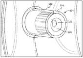
상기 밸브 조립체는 외부 팽창형 인클로저 및 내부 팽창형 인클로저의 제 1 개구들을 결합하는 밸브 코어를 포함할 수 있다. 상기 밸브 코어는 밸브 코어의 내부로부터 밸브 코어의 외부로 개구를 가질 수 있다. 밸브 멤브레인은 밸브 코어를 부분적으로 감싸고 외부 팽창형 인클로저 내로 개구를 갖는다. 밸브 멤브레인의 개구 및 밸브 코어가 서로 분리되어 물질이 역류하는 것을 방지하면서 물질을 외부 팽창형 인클로저 내로 유동시킨다. 상기 밸브 코어는 재밀봉 가능하고 천공 가능한 멤브레인을 더 포함하여 내부 팽창형 인클로저로의 접근로(access)를 제공할 수 있다.The valve assembly may include a valve core coupling first openings of an outer inflatable enclosure and an inner inflatable enclosure. The valve core may have an opening from the inside of the valve core to the outside of the valve core. The valve membrane partially encloses the valve core and has an opening into the external inflatable enclosure. The opening of the valve membrane and the valve core are separated from each other to prevent backflow of the material while allowing the material to flow into the outer inflatable enclosure. The valve core may further include a resealable and punctureable membrane to provide access to the internally inflatable enclosure.
상기 밸브 멤브레인 및 상기 밸브 코어는 일체로 성형될 수 있거나 상기 밸브 코어는 접착제에 의해 상기 밸브 멤브레인에 본딩(bond)될 수 있다.The valve membrane and the valve core may be integrally molded or the valve core may be bonded to the valve membrane by an adhesive.
상기 내부 팽창형 인클로저 및 상기 외부 팽창형 인클로저는 실리콘 러버와 같은 탄성중합체(elastomer)를 포함할 수 있다.The inner inflatable enclosure and the outer inflatable enclosure may include an elastomer such as silicone rubber.
일부 실시예에서, 경화성 물질은 외부 팽창형 인클로저를 팽창시키기 위해 제공될 수 있고, 내부 팽창형 인클로저를 팽창시키기 위해 가스와 같은 압축성 물질이 제공되어 경화된 물질을 변형시킨다. 상기 경화된 물질은 실질적으로 내부 팽창형 인클로저를 둘러쌀 수 있다. 다른 실시예에서, 내부 팽창형 인클로저를 팽창시키기 위해 비압축성 물질(예를 들면, 액체)이 제공되고 이어서 경화성 물질이 외부 팽창형 인클로저 내로 주입된다. 상기 비압축성 물질은 이어서 내부 팽창형 인클로저로부터 제거되고 압축성 물질(예를 들면 가스)로 대체된다. 소정의 실시예에서, 경화성 물질은 내부 팽창형 인클로저 및 외부 팽창형 인클로저와 더 중합되어 단단한 단일 부재를 형성한다.In some embodiments, a curable material may be provided for inflating the outer inflatable enclosure, and a compressible material, such as a gas, may be provided to inflate the inner inflatable enclosure to deform the cured material. The cured material may substantially enclose the inner inflatable enclosure. In another embodiment, an incompressible material (eg, a liquid) is provided to inflate the inner inflatable enclosure and then the curable material is injected into the outer inflatable enclosure. The incompressible material is then removed from the inner inflatable enclosure and replaced with a compressible material (eg gas). In certain embodiments, the curable material is further polymerized with the inner inflatable enclosure and the outer inflatable enclosure to form a rigid unitary piece.
예시적인 실시예에 따라, 외부 팽창형 인클로저에 연결되는 내부 팽창형 인클로저를 포함하는 이식형 보철 장치를 팽창시키기 위한 밸브 조립체는 상기 내부 팽창형 인클로저의 내부로부터 상기 외부 팽창형 인클로저의 외부로 통로를 형성하는 탄성 멤브레인 및 상기 통로 내에 배치되는 밸브 코어를 포함하여, 상기 탄성 멤브레인이 상기 밸브 코어를 둘러싸도록 한다. 상기 탄성 멤브레인은 외부 팽창형 인클로저의 내부 내로 개구를 가지며 상기 탄성 멤브레인은 밸브 코어를 둘러싼다. 상기 밸브 코어는 제 1 단부로부터 제 2 단부로 연장하는 도관, 및 상기 내부 팽창형 인클로저에 재밀봉가능한 접근로를 제공하기 위해 밸브 코어 도관의 제 2 단부에 재밀봉 가능하고 천공 가능한 멤브레인을 포함한다. 도관 내의 개구는 도관의 내부로부터 도관의 외부로 연장하고, 밸브 코어 내의 개구는 탄성 멤브레인의 개구로부터 오프셋되어 도관의 내부 내로 도입된 물질이 역류하는 것을 방지하면서 물질을 외부 팽창형 인클로저의 내부로 통과시키는 일방 밸브를 형성한다.According to an exemplary embodiment, a valve assembly for inflating an implantable prosthetic device comprising an internally inflatable enclosure coupled to an externally inflatable enclosure provides a passageway from the interior of the internally inflatable enclosure to the exterior of the externally inflatable enclosure. an elastic membrane forming and a valve core disposed within the passage, such that the elastic membrane surrounds the valve core. The elastic membrane has an opening into the interior of the outer inflatable enclosure and the elastic membrane surrounds the valve core. The valve core includes a conduit extending from a first end to a second end, and a resealable and punctureable membrane at a second end of the valve core conduit to provide a resealable access to the inner inflatable enclosure. . An opening in the conduit extends from the interior of the conduit to the exterior of the conduit, and the opening in the valve core is offset from the opening in the resilient membrane to pass material into the interior of the outer inflatable enclosure while preventing backflow of material introduced into the interior of the conduit to form a one-way valve.
예시적인 실시예에 따라, 섬유륜에 의해 둘러싸인 수핵을 갖는 추간 공간 내로 보철 장치를 이식하기 위한 방법은 상기 섬유륜을 관통하는 단계, 상기 수핵을 제거하는 단계, 및 이식형 보철 장치를 이식하는 단계를 포함하며, 상기 이식형 보철 장치는 제 1 개구를 갖는 내부 팽창형 인클로저 및 제 1 개구를 갖는 외부 팽창형 인클로저를 포함한다. 상기 외부 팽창형 인클로저는 상기 내부 팽창형 인클로저를 캡슐 형태로 둘러싼다. 밸브 조립체는 상기 외부 팽창형 인클로저의 제 1 개구 및 상기 내부 팽창형 인클로저의 제 1 개구를 밀봉 방식으로 결합하고, 상기 밸브 조립체는 상기 외부 팽창형 인클로저 및 상기 내부 팽창형 인클로저를 독립적으로 팽창하도록 구성된다. 보강 밴드는 상기 외부 팽창형 인클로저의 주변 둘레에 제공된다.According to an exemplary embodiment, a method for implanting a prosthetic device into an intervertebral space having a nucleus pulposus surrounded by an annulus fibrosus includes penetrating the annulus fibrosus, removing the nucleus pulposus, and implanting an implantable prosthetic device. wherein the implantable prosthetic device includes an inner expandable enclosure having a first opening and an outer expandable enclosure having a first opening. The outer inflatable enclosure encapsulates the inner inflatable enclosure. a valve assembly sealingly coupling the first opening of the outer inflatable enclosure and the first opening of the inner inflatable enclosure, the valve assembly being configured to independently inflate the outer inflatable enclosure and the inner inflatable enclosure do. A reinforcing band is provided around the perimeter of the outer inflatable enclosure.
일부 실시예에서, 상기 방법은 상기 내부 팽창형 인클로저를 압축성 물질을 이용하여 팽창시키는 단계를 더 포함할 수 있고, 상기 압축성 물질은 가스를 포함할 수 있다. 상기 방법은 경화성 물질을 이용하여 상기 외부 팽창형 인클로저를 팽창시키는 단계를 더 포함할 수 있고, 상기 경화성 물질은 실리콘 러버일 수 있다. 다른 실시예에서, 상기 방법은 비압축성 물질을 이용하여 상기 내부 팽창형 인클로저를 팽창시키는 단계를 더 포함할 수 있고, 상기 비압축성 물질은 액체를 포함할 수 있다. 상기 방법은 상기 외부 팽창형 인클로저를 경화성 물질을 이용하여 팽창시키는 단계, 상기 경화성 물질을 경화시키는 단계, 및 상기 내부 팽창형 인클로저 내의 비압축성 물질을 압축성 물질로 대체하는 단계를 더 포함할 수 있다.In some embodiments, the method may further comprise inflating the internally inflatable enclosure with a compressible material, wherein the compressible material may comprise a gas. The method may further comprise inflating the outer inflatable enclosure with a curable material, wherein the curable material may be a silicone rubber. In another embodiment, the method may further comprise inflating the internally inflatable enclosure with an incompressible material, the incompressible material may comprise a liquid. The method may further comprise inflating the outer inflatable enclosure with a curable material, curing the curable material, and replacing the incompressible material within the inner inflatable enclosure with a compressible material.
예시적인 실시예에 따라, 이식형 보철 장치를 생산하기 위한 방법은 (i) 보철물 블랭크(prosthesis blank)를 사출 성형하는 단계로서, 상기 보철물 블랭크는 근위 단부 및 원위 단부를 갖는 외부 멤브레인 섹션, 근위 단부 및 원위 단부를 갖는 내부 멤브레인 섹션, 상기 외부 멤브레인 섹션의 근위 단부와 상기 내부 멤브레인 섹션의 근위 단부 사이에 배치되는 밸브 섹션, 상기 내부 멤브레인 섹션의 원위 단부의 원위 플러그 내부 섹션, 및 상기 외부 멤브레인 섹션의 원위 단부의 원위 플러그 외부 섹션을 포함하는, 보철물 블랭크의 사출 성형 단계; 및 (ii) 상기 외부 멤브레인 섹션이 상기 내부 멤브레인 섹션을 둘러싸서 상기 내부 멤브레인에 의해 형성된 내부 풍선을 둘러싸는 외부 풍선을 형성하도록 상기 보철물 블랭크를 부분적으로 뒤집는 단계를 포함한다.According to an exemplary embodiment, a method for producing an implantable prosthetic device comprises the steps of (i) injection molding a prosthesis blank, the prosthesis blank comprising an outer membrane section having a proximal end and a distal end, a proximal end and an inner membrane section having a distal end, a valve section disposed between the proximal end of the outer membrane section and the proximal end of the inner membrane section, a distal plug inner section at the distal end of the inner membrane section, and injection molding of a prosthetic blank comprising a distal plug outer section at a distal end; and (ii) partially inverting the prosthesis blank such that the outer membrane section surrounds the inner membrane section to form an outer balloon surrounding the inner balloon formed by the inner membrane.
예시적인 실시예에 따라, 이식형 보철 장치를 생산하기 위한 방법은 (i) 보철물 블랭크를 형성하도록 구성된 프로파일링된(profiled) 외부 표면을 맨드렐에 제공하는 단계로서, 상기 보철물 블랭크는 근위 단부 및 원위 단부를 갖는 외부 멤브레인 섹션, 근위 단부 및 원위 단부를 갖는 내부 멤브레인 섹션, 상기 외부 멤브레인 섹션의 근위 단부와 상기 내부 멤브레인 섹션의 근위 단부 사이에 배치되는 밸브 섹션, 상기 내부 멤브레인 섹션의 원위 단부의 원위 플러그 내부 섹션, 및 상기 외부 멤브레인 섹션의 원위 단부의 원위 플러그 외부 섹션을 포함하는, 단계; (ii) 상기 보철물 블랭크를 형성하기 위하여 상기 맨드렐에 물질을 코팅하는 단계; (iii) 상기 맨드렐로부터 상기 보철물 블랭크를 벗기는 단계; 및 (iv) 상기 외부 멤브레인 섹션이 상기 내부 멤브레인 섹션을 둘러싸서 상기 내부 멤브레인에 의해 형성된 내부 풍선을 둘러싸는 외부 풍선을 형성하도록 상기 보철물 블랭크를 부분적으로 뒤집는 단계를 포함한다.According to an exemplary embodiment, a method for producing an implantable prosthetic device comprises the steps of (i) providing a mandrel with a profiled outer surface configured to form a prosthetic blank, the prosthetic blank comprising a proximal end and an outer membrane section having a distal end, an inner membrane section having a proximal end and a distal end, a valve section disposed between the proximal end of the outer membrane section and the proximal end of the inner membrane section, distal to the distal end of the inner membrane section a plug inner section and a distal plug outer section at the distal end of the outer membrane section; (ii) coating the mandrel with a material to form the prosthesis blank; (iii) peeling the prosthesis blank from the mandrel; and (iv) partially inverting the prosthesis blank such that the outer membrane section surrounds the inner membrane section to form an outer balloon surrounding an inner balloon formed by the inner membrane.
상기 맨드렐은 단일 몸체를 포함할 수 있고, 상기 맨드렐의 밸브 섹션은 상기 보철물 블랭크와 일체형으로 성형되는 밸브 코어를 포함할 수 있다. 상기 맨드렐은 상기 밸브 코어에 결합되는 두 개의 분리가능한 피스를 포함할 수 있고, 상기 맨드렐로부터 상기 보철물 블랭크를 벗기는 단게는 상기 밸브 코어로부터 상기 맨드렐 피스를 분리하는 단계 및 상기 보철물 블랭크로부터 상기 분리가능한 피스를 제거하는 단계를 포함할 수 있다.The mandrel may include a single body, and the valve section of the mandrel may include a valve core integrally molded with the prosthesis blank. The mandrel may comprise two separable pieces coupled to the valve core, wherein peeling the prosthesis blank from the mandrel comprises separating the mandrel piece from the valve core and removing the prosthesis blank from the prosthesis blank. removing the separable piece.
상기 밸브 코어는 상기 밸브 섹션 내로 접착될 수 있다.The valve core may be glued into the valve section.
상기 원위 플러그는 상기 원위 플러그 외부 섹션을 밀봉하기 위하여 상기 원위 플러그 외부 섹션 내로 삽입될 수 있으며, 상기 원위 플러그 및 원위 플러그 외부 섹션은 상기 원위 플러그 내부 섹션 내로 삽입될 수 있다.The distal plug may be inserted into the distal plug outer section to seal the distal plug outer section, and the distal plug and distal plug outer section may be inserted into the distal plug inner section.
보강 밴드는 상기 원위 플러그에 연결될 수 있고, 상기 보강 밴드, 원위 플러그, 및 원위 플러그 외부 섹션은 상기 원위 플러그 내부 섹션 내로 삽입될 수 있다. 상기 보강 밴드는 고정 장치에 의해 상기 원위 플러그에 연결될 수 있다.A reinforcing band may be connected to the distal plug, and the reinforcing band, distal plug, and distal plug outer section may be inserted into the distal plug inner section. The reinforcing band may be connected to the distal plug by a fixation device.
상기 맨드렐은 실리콘 분산액을 포함할 수 있는 중합체 액체 내로 침지됨으로써 코팅되어 건조될 수 있다.The mandrel may be coated and dried by dipping into a polymer liquid, which may include a silicone dispersion.
상기 탄성 멤브레인은 상기 맨드렐을 용융시킴으로써 상기 맨드렐로부터 벗겨질 수 있거나, 상기 보철물 블랭크는 상기 맨드렐 위로 신장시킴으로써 상기 맨드렐로부터 제거될 수 있다. 보강 밴드는 상기 외부 풍선의 주변 둘레에 도포될 수 있다.The elastic membrane may be peeled off from the mandrel by melting the mandrel, or the prosthesis blank may be removed from the mandrel by stretching over the mandrel. A reinforcement band may be applied around the perimeter of the outer balloon.
예시적인 실시예에 따라, 이식형 보철 장치를 생산하기 위한 맴드렐은 제 1 풍선의 형태로 구성된 프로파일링된 외부 표면을 갖는 제 1 풍선 맨드렐; 제 2 풍선의 형태로 구성된 프로파일링된 외부 표면을 갖는 제 2 풍선 맨드럴; 및 제 1 풍선 맨드렐과 제 2 풍선 맨드렐 사이에 배치되는 밸브 코어를 포함한다. 상기 제 1 풍선 맨드렐의 외부 표면은 원위 개구 섹션을 더 포함할 수 있고, 상기 제 2 풍선 맨드렐의 외부 표면은 원위 개구 섹션을 포함할 수 있다. 상기 풍선 맨드렐들의 외부 표면들은 곡선형일 수 있다. 상기 풍선 맨드렐들 각각의 외부 표면들은 대체적으로 균일한 직경을 갖는 중앙 섹션을 포함할 수 있다.According to an exemplary embodiment, a mandrel for producing an implantable prosthetic device includes a first balloon mandrel having a profiled outer surface configured in the shape of a first balloon; a second balloon mandrel having a profiled outer surface configured in the shape of a second balloon; and a valve core disposed between the first balloon mandrel and the second balloon mandrel. The outer surface of the first balloon mandrel may further include a distal opening section and the outer surface of the second balloon mandrel may include a distal opening section. The outer surfaces of the balloon mandrels may be curved. The outer surfaces of each of the balloon mandrels may include a central section having a generally uniform diameter.
예시적인 실시예에 따라, 이식형 보철 장치를 생산하기 위한 맨드렐은 프로파일링된 외부 표면을 갖는 단일 몸체를 포함한다. 상기 프로파일링된 외부 표면은 근위 단부 및 원위 단부를 갖는 고리형 풍선을 형성하도록 구성된 외부 멤브레인 섹션; 근위 단부 및 원위 단부를 갖는 핵 풍선을 형성하도록 구성된 내부 멤브레인 섹션; 상기 외부 멤브레인 섹션의 근위 단부와 상기 내부 멤브레인 섹션의 근위 단부 사이에 배치되는 밸브 조립체를 수용하도록 구성된 밸브 섹션; 상기 외부 멤브레인 섹션의 원위 단부에서 원위 플러그를 수용하도록 구성된 원위 플러그 외부 섹션; 및 상기 내부 멤브레인 섹션의 원위 단부에서 상기 원위 플러그 및 상기 원위 플러그 외부 섹션의 조립체를 수용하도록 구성된 원위 플러그 내부 섹션을 갖는다.According to an exemplary embodiment, a mandrel for producing an implantable prosthetic device comprises a single body having a profiled outer surface. The profiled outer surface comprises: an outer membrane section configured to form an annular balloon having a proximal end and a distal end; an inner membrane section configured to form a nuclear balloon having a proximal end and a distal end; a valve section configured to receive a valve assembly disposed between the proximal end of the outer membrane section and the proximal end of the inner membrane section; a distal plug outer section configured to receive a distal plug at a distal end of the outer membrane section; and a distal plug inner section configured to receive an assembly of the distal plug and the distal plug outer section at the distal end of the inner membrane section.
용어 "결합된(coupled)"은, 비록 반드시 직접적으로 연결되지 않더라도, 연결된 것으로서 정의된다. 용어 "하나의(a 및 an)"는 본 개시물이 명확히 달리 요구하지 않는 한 하나 또는 그 초과로서 정의된다. 용어 "실질적으로(substantially)", "대략(approximately)" 및 "약(about)"은 당업자에 의해 이해되는 바와 같이, 주로 구체화된 것 전체이지만 반드시 전체는 아닌 것으로 정의된다(구체화된 것을 포함함, 예를 들면, 실질적으로 90도는 90도를 포함하고 실질적으로 평행한 것은 평행한 것을 포함함). 임의의 개시된 실시예에서, 용어 "실질적으로", "대략" 및 "약"은 구체화된 것의 "[비율(percentage)] 내"로 대체될 수 있고 여기서 상기 비율은 0.1, 1, 5, 및 10 퍼센트를 포함한다.The term “coupled” is defined as being coupled, although not necessarily directly coupled. The terms “a and an” are defined as one or more unless the disclosure clearly requires otherwise. The terms “substantially”, “approximately” and “about” are defined primarily as all but not necessarily all of the specified (including the specified), as understood by one of ordinary skill in the art. , eg, substantially 90 degrees includes 90 degrees and substantially parallel includes parallel). In any disclosed embodiment, the terms “substantially”, “approximately” and “about” may be replaced with “within [percentage]” of the specified, wherein the ratio is 0.1, 1, 5, and 10 includes percentages.
용어 "포함하다(comprise)"(및 "comprises" 및 "comprising"과 같은 comprise의 모든 형태), "가지다(have)"(및 "has" 및 "having"과 같은 have의 모든 형태), "포함하다(include)"(및 "includes" 및 "including"과 같은 include의 모든 형태), 및 "함유하다(contain)"(및 "contains" 및 "containing"과 같은 contain의 모든 형태)는 개방형 연결 동사이다. 결과적으로, 하나 또는 그 초과의 요소들 또는 특징들을 "포함하는", "가지는", "포함하는" 또는 "함유하는" 시스템, 또는 시스템의 구성요소는 하나 또는 그 초과의 요소들 또는 특징들을 갖지만, 단지 이러한 요소들 또는 특징들만을 갖는 것으로 제한되지는 않는다. 또한, 하나 또는 그 초과의 단계들을 "포함하고", "가지고", "포함하고", 또는 "함유하는" 방법은 하나 또는 그 초과의 단계들을 갖지만 이러한 하나 또는 그 초과의 단계들만을 갖는 것으로 제한되지는 않는다. 부가적으로, "제 1(first)" 및 "제 2(second)"와 같은 용어들은 구조들 또는 특징들을 구별하기 위해서만 이용되며, 상이한 구조들 또는 특징들을 특별한 순서로 제한하기 위해 이용되지는 않는다.The terms "comprise" (and all forms of comprise such as "comprises" and "comprising"), "have" (and all forms of have such as "has" and "having"), "include" "include" (and all forms of include, such as "includes" and "including"), and "contain" (and all forms of contain, such as "contains" and "containing") are open linking verbs to be. Consequently, a system, or component of a system, “comprising”, “having”, “comprising” or “containing” one or more elements or features, has the one or more elements or features, but , but not limited to having only these elements or features. Also, a method “comprising”, “having”, “comprising”, or “comprising” one or more steps has one or more steps but is limited to having only such one or more steps. it doesn't happen Additionally, terms such as “first” and “second” are used only to distinguish between structures or features, and not to limit the different structures or features to a particular order. .
특정 방식으로 구성되는 장치, 시스템, 또는 구성요소는 적어도 상기 방식으로 구성되지만, 상기 장치, 시스템, 또는 구성요소는 또한 구체적으로 설명된 것이 아닌 다른 방식으로 구성될 수 있다.Although an apparatus, system, or component configured in a particular way is configured at least in that way, the device, system, or component may also be configured in other ways than specifically described.
시스템들 및 방법들 중 어느 하나의 임의의 실시예는 설명된 요소들, 특징들, 및/또는 단계들 중 어느 하나를 포함하고/포함하고/함유하고/가지는 것이 아닌 설명된 요소들, 특징들, 및/또는 단계들 중 어느 하나로 이루어지거나 이들을 필수 구성으로 이루어질 수 있다. 따라서, 청구항들 중 어느 하나의 청구항에서, 개방형 연결 동사를 이용하는 것으로부터 주어진 청구항의 범위를 변경시키기 위하여 상기 용어 "이루어지는(consisting of)" 또는 "필수 구성으로 이루어지는(consisting essentially of)"은 상술된 개방형 연결 동사들 중 어느 하나로 대체될 수 있다.Any embodiment of any one of the systems and methods includes/includes/contains/does not have any of the described elements, features, and/or steps described elements, features, and/or steps. , and/or any one of the steps or may consist of the essential components. Thus, in any one of the claims, the term “consisting of” or “consisting essentially of” refers to the above-mentioned terms in order to alter the scope of a given claim from using an open linking verb. It can be replaced with any of the open connective verbs.
비록 설명되거나 예시되지는 않았지만, 본 개시 또는 실시예의 본질에 의해 명확히 금지되지 않는 경우, 하나의 실시예의 특징 또는 특징들은 다른 실시예들에 적용될 수 있다.Although not described or illustrated, a feature or features of one embodiment may be applied to other embodiments, unless expressly prohibited by the nature of the present disclosure or embodiment.
위에서 설명된 실시예 및 다른 실시예들과 관련된 상세가 아래에 제시된다.Details relating to the embodiment described above and other embodiments are presented below.
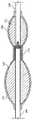
도 1은 본 발명의 일 실시예에 따른 팽창된 임플란트의 사시도이며;
도 2는 다를 방향으로부터 본, 도 1의 팽창된 임플란트의 사시도이며;
도 3은 도 1의 임플란트의 평면도이며;
도 4는 도 2의 4-4 선을 통하여 취한 단면도이며;
도 5는 도 2의 5-5 선을 통하여 취한 단면도이며;
도 6은 도 1의 임플란트의 임플란트 밸브의 일 부분의 절개도이며;
도 7은 도 6의 임플란트 밸브의 일 부분의 절개도이며;
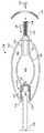
도 8은 원위 플러그의 삽입 및 고리형 보강 부재의 부착 전의 임플란트 조립체의 단면도이며;
도 9는 본 발명의 일 실시예에 따른 맨드렐 및 임플란트의 단면도이며;
도 10은 도 1의 임플란트 조립체에 대한 제 1 조립 단계를 예시하며;
도 11은 도 1의 임플란트 조립체에 대한 제 2 조립 단계를 예시하며;
도 12는 도 1의 임플란트 조립체에 대한 제 3 조립 단계를 예시하며;
도 13은 도 1의 임플란트 조립체에 대한 제 4 조립 단계를 예시하며;
도 14는 본 발명의 다른 실시예에 따른 맨드렐 및 임플란트 조립체의 단면도이며;
도 15는 도 1의 임플란트 조립체에 대한 제 1 조립 단계를 예시하며;
도 16은 도 1의 임플란트 조립체에 대한 제 2 조립 단계를 예시하며;
도 17은 도 1의 임플란트 조립체에 대한 제 3 조립 단계를 예시하며;
도 18은 도 1의 임플란트 조립체에 대한 제 4 조립 단계를 예시하며;
도 19는 도 1의 임플란트 조립체에 대한 최종 조립 단계를 예시하며;
도 20은 도 1의 임플란트 조립체를 이식하는데 있어서의 제 1 단계를 예시하며;
도 21은 도 1의 임플란트 조립체를 이식하는데 있어서의 제 2 단계를 예시하며;
도 22는 도 1의 임플란트 조립체를 이식하는데 있어서의 제 3 단계를 예시하며;
도 23은 도 1의 임플란트 조립체를 이식하는데 있어서의 제 4 단계를 예시한다.1 is a perspective view of an expanded implant according to an embodiment of the present invention;
Fig. 2 is a perspective view of the expanded implant of Fig. 1, seen from a different direction;
3 is a plan view of the implant of FIG. 1 ;
Fig. 4 is a cross-sectional view taken along line 4-4 of Fig. 2;
Fig. 5 is a cross-sectional view taken along line 5-5 of Fig. 2;
Fig. 6 is a cutaway view of a portion of the implant valve of the implant of Fig. 1;
7 is a cutaway view of a portion of the implant valve of FIG. 6 ;
8 is a cross-sectional view of the implant assembly prior to insertion of the distal plug and attachment of the annular reinforcement member;
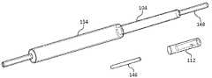
9 is a cross-sectional view of a mandrel and implant according to an embodiment of the present invention;
Fig. 10 illustrates a first assembly step for the implant assembly of Fig. 1;
11 illustrates a second assembly step for the implant assembly of FIG. 1 ;
Fig. 12 illustrates a third assembly step for the implant assembly of Fig. 1;
Fig. 13 illustrates a fourth assembly step for the implant assembly of Fig. 1;
14 is a cross-sectional view of a mandrel and implant assembly according to another embodiment of the present invention;
15 illustrates a first assembly step for the implant assembly of FIG. 1 ;
16 illustrates a second assembly step for the implant assembly of FIG. 1 ;
Fig. 17 illustrates a third assembly step for the implant assembly of Fig. 1;
18 illustrates a fourth assembly step for the implant assembly of FIG. 1 ;
Figure 19 illustrates the final assembly steps for the implant assembly of Figure 1;
20 illustrates a first step in implanting the implant assembly of FIG. 1 ;
FIG. 21 illustrates a second step in implanting the implant assembly of FIG. 1 ;
22 illustrates a third step in implanting the implant assembly of FIG. 1 ;
23 illustrates a fourth step in implanting the implant assembly of FIG. 1 .
아래의 상세한 설명에서, 첨부 도면들이 참조되며, 이 도면들에서는 본 발명의 예시적이고 비-제한적이고 비-배타적인 실시예들이 도시된다. 이러한 실시예들은 당업자가 본 발명을 실시할 수 있도록 충분히 상세히 설명되며, 본 발명의 사상 또는 범위로부터 벗어나지 않으면서 다른 실시예들이 이용될 수 있고 다른 변경이 이루어질 수 있다는 것이 이해된다. 따라서, 아래의 상세한 설명은 제한된 의미로 받아들이지 않으며, 본 발명의 범위는 첨부된 청구항들에 의해서만 정의된다. 첨부된 도면들에서, 동일한 도면부호는 달리 특정되지 않는 한, 다양한 도면들을 통하여 동일한 부분들을 지칭한다.DETAILED DESCRIPTION In the following detailed description, reference is made to the accompanying drawings, in which illustrative, non-limiting and non-exclusive embodiments of the invention are shown. These embodiments are described in sufficient detail to enable those skilled in the art to practice the invention, and it is understood that other embodiments may be utilized and other changes may be made without departing from the spirit or scope of the invention. Accordingly, the following detailed description is not to be taken in a limiting sense, and the scope of the invention is defined solely by the appended claims. In the accompanying drawings, like reference numerals refer to like parts throughout the various drawings, unless otherwise specified.
임플란트의 설명Description of implants
도 1 내지 도 8을 참조하면, 경피적으로 전달가능한 척추 임플란트(100)의 일 실시예는 외부 팽창형 인클로저(또는 풍선)(102) 및 내부 팽창형 인클로저(또는 풍선)(104)를 포함한다. 외부 팽창형 인클로저(102)는 고리형 챔버(106)를 형성하고 내부 팽창형 인클로저(104)는 핵 챔버(108)를 형성한다. 핵 챔버(108)는 고리형 챔버(106) 내에 캡슐 형태로 둘러싸여 있다. 바람직하게는, 외부 팽창형 인클로저(102) 및 내부 팽창형 인클로저(104)는 실리콘 러버와 같은 탄성 물질(elastomeric material)의 솔기가 없는 단일 피스로서 형성된다. 탄성 물질의 이용은 유연한(compliant) 외부 풍선(102) 및 내부 풍선(104)을 생산한다. 즉, 내압이 인가될 때 외부 풍선(102) 및 내부 풍선(104)은 팽창한다. 유연한 풍선들의 이용은 소정의 장점을 제공한다. 유연한 풍선들은 핵 공간의 불규칙적인, 평면형 또는 원반형 구성을 수용한다. 더욱이, 유연한 풍선은 탄성 경화가 후속하는 핵 임플란트의 적절한 탄성 계수를 유지하고, 척추 세그먼트의 생체-기계적 이동성을 유지하고 경화된 실리콘 구성요소의 중심 보이드(void) 로의 변형이 방해받지 않는다.1-8 , one embodiment of a percutaneously deliverable
고리형 보강 밴드(110)는 임플란트(100)의 측면 에지의 주변 둘레에 배치될 수 있어 원주 방향으로의 탄성 멤브레인의 과 신장 또는 외부 풍선(102) 및 내측 풍선(104)의 과 팽창을 최소화하거나 방지한다. 고리형 보강 밴드(110)는 수직 방향 팽창을 조장하여 디스크 공간을 확대한다. 척추 상부 및 하부 단부판은 임플란트(100)의 팽창을 억제한다.The
임플란트가 수축되면서 핵이 제거된 추간판 공간 내로 경피적으로 삽입되고나서 핵이 제거된 공동을 충진하기 위해 팽창되도록 임플란트(100)의 크기가 선택된다. 일 실시예에서, 팽창된 임플란트(100)의 외부는 길이가 약 30mm, 폭이 약 20mm, 및 높이가 약 10mm이고, 내부 팽창형 인클로저(104)의 외부는 길이가 약 9mm, 폭이 약 6mm, 및 두께가 약 6mm이다.The size of the
고리형 보강 밴드(110)는 생체 적합성 섬유 물질일 수 있다. 일 실시예에서, 고리형 보강 밴드(110)는 관형 직조 섬유 물질을 포함한다. 고리형 보강 밴드(110)는 또한 팽창형 부재를 포함할 수 있어 부가 지지를 제공한다. 팽창형 부재는 니티놀(nitinol)과 같은, 형상 기억 물질로 형성될 수 있다. 발명의 명칭이 경피로 이식가능한 핵 임플란트인, 미국 특허 제 8,636,803호는 고리형 보강 밴드(110)의 하나의 적절한 구성을 개시하며, 이 미국 특허는 전체가 모든 목적을 위해 인용에 의해 본원에 포함된다.The
외부 팽창형 인클로저(102)는 제 1 개구(118) 및 제 2 개구(120)를 갖는다. 내부 팽창형 인클로저(104)는 제 1 개구(136) 및 제 2 개구(138)를 갖는다. 근위 플러그, 또는 밸브 코어(112)는 제 1 개구(118) 및 제 1개구(136)를 연결한다. 밸브 멤브레인(122)은 근위 플러그(112)를 둘러싸고 근위 플러그(112)와 협동하여 팽창 밸브(124)를 형성한다. 팽창 밸브(124)는 물질을 고리형 챔버(106) 내로 도입하는 일방 밸브이다. 바림직하게는, 밸브 멤브레인(122)은 아래에서 더 상세하게 설명되는 바와 같이 외부 팽창형 인클로저(102) 및 내부 팽창형 인클로저(104)와 일체로 형성된다. 도 6 내지 도 8에서 가장 확실히 볼 수 있는 바와 같이, 근위 플러그(112)는 제 1 단부(128)로부터 제 2 단부(130)로 연장하는 도관(126)을 포함한다. 근위 플러그(112)의 제 1 단부(128)는 팽창 스타일러스(inflation stylus: 116)를 수용하기 위한 포트(114)를 형성한다. 밸브 멤브레인(122)은 실질적으로 액밀 상태인, 제 1 접착 밴드(140) 및 제 2 접착 밴드(142)에 의해 근위 플러그(112)에 결합된다. 제 1 접착 밴드(140) 및 제 2 접착 밴드(142) 사이의 밸브 멤브레인(122)의 부분은 본딩되지 않아서 물질을 채널을 통하여 유동시키기 위한 채널을 형성한다. 적어도 하나의 개구(132)는 도관(126)으로부터 근위 플러그(112)의 외부로 연장한다. 밸브 멤브레인(122)은 개구(132)로부터 오프셋되는 적어도 하나의 개구(134)를 갖는다. 이러한 방식으로, 적절한 물질(아래에서 상세하게 설명됨)이 압력하에서 도관(126) 내로 도입될 때, 상기 물질은 개구(132)를 통하여 고리형 챔버(106) 내로 도입되어 밸브 멤브레인(122)을 신장시키고 개구(134)를 통하여 유출한다. 압력이 도관(126)으로부터 제거될 때, 밸브 멤브레인(122)은 개구(132)를 밀봉하고 개구(132)를 통한 역류를 방지한다. 도관(126)의 제 2 단부(130)는 천공가능하고, 재밀봉 가능한 멤브레인(144)에 의해 폐쇄된다.The outer
원위 플러그(146)는 내부 팽창형 인클로저(104)의 제 2 개구(138)로부터 연장하는 목부(148)에 배치된다. 원위 플러그(148)는 목부(148)에 본딩되어 액밀 밀봉을 형성한다. 원위 플러그(146) 및 목부(148) 조립체는 외부 팽창형 인클로저(102)의 제 2 개구(120)로부터 연장하는 목부(150) 내에 배치된다. 고리형 보강 밴드(110)는 원위 플러그(146) 및 목부(148) 조립체와 목부(150) 사이에 포획되어 보강 밴드(110)에 대한 고정물로서 기능한다. 대안적으로, 고정 장치(152)는 도 9에서 가장 확실히 보여지는 바와 같이, 고리형 보강 밴드(110)를 원위 플러그(146)에 고정하기 위해 이용될 수 있다.The
임플란트 제조 방법Implant Manufacturing Method
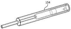
도 9 내지 도 13을 참조하면, 일 실시예에서, 내부 팽창형 인클로저(102) 및 외부 팽창형 인클로저(104)는 단일 임플란트 블랭크(154)로 형성된다. 임플란트 블랭크(154)는 맨드렐(156)을 이용하여 딥 성형함으로써 생산될 수 있다. 맨드렐(156)은 외부 멤브레인 섹션(158), 내부 멤브레인 섹션(160), 및 밸브 섹션(162)을 포함한다. 맨드렐(156)은 하나의 피스 또는 다수의 피스로 이루어질 수 있다. 일 실시예에서, 외부 멤브레인 섹션(158), 내부 멤브레인 섹션(160), 및 밸브 섹션(162)은 서로 조립되는 개별 피스들이다. 맨드렐(156)은 실리콘 분산액과 같은 중합체 액체 내로 침지되고, 액체로부터 제거되고 건조 또는 경화된다. 맨드렐(156)은 맨드렐의 원하는 두께를 형성하기 위하여 한번 또는 여러번 침지될 수 있다. 블랭크(154)는 목부(150), 외부 팽창형 인클로저(102), 밸브 멤브레인(122), 내부 팽창형 인클로저(104), 및 목부(148)를 포함한다.9-13 , in one embodiment, the inner
경화 또는 건조 후, 임플란트 블랭크(154)는 맨드렐(156)로부터 벗겨진다. 이는 맨드렐(156) 위로 임플란트 블랭크(154)를 신장시킴으로써 달성될 수 있다. 맨드렐(156)이 분리가능한 피스들로 이루어진 경우, 맨드렐은 벗겨지기 전에 조립 해제될 수 있다. 일 실시예에서, 맨드렐(156)은 용융가능하거나 용해가능한 물질로 형성될 수 있고 맨드렐(156)로부터 임플란트 블랭크(154)를 벗기기 위해 용융되거나 용해될 수 있다. 밸브 멤브레인(122)을 통한 개구(134)는 임플란트 블랭크(154)에 형성된다.After curing or drying, the implant blank 154 is peeled off the
도 10 내지 도 13을 참조하면, 임플란트 블랭크(154), 원위 플러그(146) 및 근위 플러그(또는 밸브 코어)(112)가 제공된다. 내부 팽창형 인클로저(104)로부터 연장하는 목부(148)는 내부 팽창형 인클로저(104)의 내부로 뒤집히고 원위 플러그(146)는 목부(148) 내로 삽입되어 제 위치에 접착된다. 목부는 고리형 챔버(106) 내로 더 뒤집힌다. 다음으로, 근위 플러그(112)는 밸브 멤브레인(122) 내로 삽입되어 접착된다. 이는 두 개의 단계들로 수행된다. 먼저, 고리형 챔버(106)에 가장 근접한 근위 플러그(112)의 단부는 제 1 접착 밴드(142)에 의해 밸브 멤브레인(122)에 접착된다. 다음으로, 임플란트 블랭크(154)가 더 뒤집히고, 제 2 접착 밴드(142)가 도포되어 임플란트 블랭크(154)를 근위 플러그(112)의 제 2 단부에 접착한다. 이는 도 12에서 도시된 바와 같은 구성을 초래한다. 다음으로, 도 13에 도시된 바와 같이, 목부(150)가 외부 팽창형 인클로저(102) 내로 (도 8에서 화살표로 표시된 바와 같이) 그리고 원위 플러그(146) 및 목부(148) 위로 밀어 넣어진다. 동시에 고리형 보강 밴드(110)가 밀어 넣어질 수 있거나 고정 장치에 의해 원위 플러그(146)에 고정될 수 있다.10-13 , an implant blank 154 , a
다른 실시예에서, 임플란트 블랭크(154)는 종래 기법을 이용하여 맨드렐 위로 사출 성형됨으로써 형성된다. 즉, 맨드렐은 임플란트 블랭크의 외측 형상에 대응하는 공동을 가지는 사출 몰드 내에 배치되고 경화성 물질이 압력하에서 몰드 내로 주입된다. 경화성 물질은 경화되고, 이에 의해 맨드렐 위에 임플란트 블랭크(154)를 형성한다. 맨드렐 및 임플란트 블랭크(154)는 이어서 사출 몰드로부터 제거된다. 임플란트 블랭크(154)가 형성되면, 나머지 조립 단계들은 앞의 문단에서 설명된 바와 같다.In another embodiment, the implant blank 154 is formed by injection molding onto a mandrel using conventional techniques. That is, the mandrel is placed in an injection mold having a cavity corresponding to the outer shape of the implant blank and the curable material is injected into the mold under pressure. The curable material is cured, thereby forming an implant blank 154 over the mandrel. The mandrel and implant blank 154 are then removed from the injection mold. Once the implant blank 154 is formed, the remaining assembly steps are as described in the preceding paragraph.
도 14 내지 도 19는 임플란트(100)를 제조하는 다른 방법을 예시한다. 이러한 실시예에서, 맨드렐(164)은 외부 멤브레인 섹션(168)을 형성하는 제 1 맨드렐 섹션(166) 및 내부 멤브레인 섹션(170)을 형성하는 제 2 맨드렐 섹션(168)을 포함한다. 제 1 맨드렐 섹션(166)은 밸브 코어(또는 근위 플러그)(112) 내로 삽입되고, 제 2 맨드렐 섹션은 근위 플러그(112)의 다른 단부와 정합된다. 도 15를 참조하면, 맨드렐 및 밸브 조립체는 이어서 임플란트 블랭크(176)를 형성하기 위하여 딥 성형된다. 도 16을 참조하면, 임플란트 블랭크(176)의 목부(188)가 뒤집히고 근위 플러그는 목부(188) 내로 접착된다. 밸브 멤브레인(192)은 플러그 섹션 위에 도포되어 제 1 접착 밴드 및 제 2 접착 밴드에 의해 플러그 섹션에 접착되어 임플란트 밸브를 형성한다. 임플란트 블랭크(176)는 이어서 도 18에 도시된 바와 같이, 밸브 코어(112) 위에 좌측으로부터 우측으로 뒤집어진다. 마지막으로, 목부(190)는 외부 팽창형 인클로저(102) 내로 밀어 넣어진다. 동시에 고리형 보강 밴드(110)가 밀어 넣어질 수 있거나 고정 장치에 의해 원위 플러그(146)에 고정될 수 있다.14-19 illustrate another method of manufacturing the
임플란트 배치 방법How to place an implant
도 20 내지 도 23을 참조하면, 팽창형 임플란트(100)는 최소 침습적 또는 경피적 수술 기법을 이용하는 배치에 특히 매우 적합하다. 배치를 위한 팽창형 임플란트(100)를 준비하기 위하여, 임플란트는 수축 및 신장되어 임플란트의 단면 프로파일을 최소화한다. 삽입 스타일러스(116)는 포트(114) 내로 분리가능하게 삽입되고 이어서 임플란트(100)가 배치 캐뉼러(180) 내로 삽입된다. 배치 캐뉼러(180)는 최소 단면 프로파일을 갖는다.20-23, the
도 20을 참조하면, 팽창형 임플란트(100)를 이식하기 위하여, 섬유륜(178)을 실질적으로 온전한 상태로 남겨두면서 추간판 절제술을 수행함으로써 현존하는 수핵이 제거된다. 바람직하게는, 추간판 절제술은 섬유륜(178)을 관통하는 소형 개구를 남겨두는 경피적 기법과 같은 최소 침습적 수술 기법을 이용하여 수행된다. 수핵이 제거되면, 섬유륜(178) 및 척추 단부판(182 및 184)은 실질적으로 빈 디스크 공동(182)을 형성한다.Referring to FIG. 20 , in order to implant the
수핵이 제거된 후, 임플란트(100)가 미리 적재된 배치 캐뉼러(180)가 빈 디스크 공동(182) 내로 배치된다. 도 21에 도시된 바와 같이 임플란트를 배치 캐뉼러의 밖으로 밀어서 빈 디스크 공동 내로 밀어냄으로써 임플란트(100)가 배치된다. 임플란트(100)는 팽창되지 않은 상태에 있다.After the nucleus pulposus has been removed, a
일 실시예에서, 핵 챔버(108)가 가스와 같은 압축성 유체(194)에 의해 먼저 팽창된다. 이는 팽창 스타일러스(116)를 통하여 전달되고 천공가능하고 재밀봉 가능한 멤브레인(144)을 통하여 가압되는 니들(도시 안됨)을 이용하여 수행될 수 있다. 압축성 유체는 내부 팽창형 인클로저(104)를 팽창시키기 위해 핵 챔버(108) 내로 배치된다. 핵 챔버(108)의 압력이 중량 지지 및 척추 이동 동안 경화된 탄성중합체(186)의 내측 변형을 위한 완충 지대를 제공하도록 핵 챔버의 압력이 선택된다. 핵 챔버(108)가 원하는 압력으로 팽창되면, 니들은 핵 챔버(108)로부터 철회된다. 다른 실시예에서, 제거가능한 니들을 이용하는 대신, 팽창 스타일러스(116)는 스타일러스를 두 개의 루멘으로 나누기 위해 스타일러스를 통하여 연장하는 격벽을 가질 수 있다. 하나의 루멘은 재밀봉 가능하고 천공 가능한 멤브레인(144)을 통하여 핵 챔버(108) 내로 연장하고 다른 루멘은 밸브(124) 및 고리형 챔버(106)를 이식하기 위하여 현장 경화성 물질을 전달한다.In one embodiment, the
팽창 스타일러스(116)는 일방 임플란트 밸브(124)(도 22)를 통하여 현장 경화성 물질을 고리형 챔버(106)로 전달하기 위해 이용된다. 경화성 물질은 바람직하게는 실리콘 러버와 같은 탄성 물질이며, 이 탄성 물질은 단일 부재를 형성하도록 내부 팽창형 인클로저(102) 및 외부 팽창형 인클로저(104)의 물질과 더 중합한다. 경화성 물질의 탄성 계수 및 다른 특성은 환자 특정 파라미터를 기초로 하여 선택될 수 있다. 예를 들면, 더 젊고 더 활동적인 환자는 이동이 적은 노인 환자보다 더 단단한 물질을 필요로 할 수 있다. 고리형 챔버(106)가 원하는 압력으로 팽창되면, 팽창 스타일러스(116)는 제거될 수 있다. 임플란트 밸브(124)는 경화성 물질이 고리형 챔버(106)의 밖으로 누출되는 것을 방지한다.The
경화성 물질이 경화된 후, 임플란트(100)는 압축성 물질(194)로 충진되는 핵 챔버(108)를 둘러싸는 경화된 탄성중합체(186)의 고리형 링을 포함한다. 이러한 구조는 추간판 공간 상에 배치되는 수직 방향 및 수평 방향 부하 응력이 외측 대신에 핵 챔버(108)을 향하여 내측 중앙으로(도 23의 화살표 방향 참조) 재지향된다. 더욱이, 고리형 보강 밴드(110)는 원래의(native) 섬유륜(178)의 조직 성장을 조장하여, 원래의 섬유륜(178)에 대한 보강을 제공한다.After the curable material has cured, the
다른 실시예에서, 핵 챔버(108)가 먼저 액체와 같은 비압축성 유체에 의해 팽창된다. 이는 전술된 바와 같이, 바늘 또는 팽창 스타일러스를 이용하여 수행될 수 있다. 핵 챔버(194)가 팽창되면, 현장 경화성 물질을 일방 임플란트 밸브(124)를 통하여 고리형 챔버(106)에 전달하기 위해 팽창 스타일러스(116)가 이용된다. 고리형 물질이 경화된 후, 비압축성 유체가 핵 챔버(108)로부터 제거되고 압축성 물질(194)로 대체된다. 이는 임플란트 밸브(124)를 이용하여 바늘에 의해 수행될 수 있다.In another embodiment, the
상기 명세서 및 예는 예시적인 실시예의 구조 및 이용의 완전한 설명을 제공한다. 비록 특정 실시예가 어느 정도의 특수성으로 또는 하나 또는 그 초과의 개별 실시예들을 가지고 전술되었지만, 당업자는 본 발명의 범위로부터 벗어나지 않으면서 개시된 실시예에 대한 다양한 변경을 수행할 수 있다. 이와 같이, 본 장치의 다양하고 예시적인 실시예는 개시된 특별한 형태로 제한되는 것을 의도하지 않는다. 오히려, 상기 실시예는 청구항들의 범위 내에서 있는 모든 변경 및 변형을 포함하고, 도시된 것 이외의 실시예들이 설명된 실시예의 특징들의 일부 또는 전부를 포함할 수 있다. 예를 들면, 구성요소들은 단일 구조로서 조합될 수 있으며, 및/또는 연결들이 대체될 수 있다(예를 들면, 나사 결합은 가압-조립 또는 용접으로 대체될 수 있다). 또한, 적절한 경우, 전술된 예들 중 어느 하나의 예의 양태들은 유사하거나 상이한 특성을 갖고 동일하거나 상이한 문제점들을 해결하기 위한 추가 예를 형성하기 위해 설명된 다른 예들 중 어느 한 예의 양태들과 조합될 수 있다. 유사하게, 전술된 이익 및 장점이 하나의 실시예에 관련될 수 있거나 수 개의 실시예들에 관련될 수 있는 것이 이해될 것이다.The above specification and examples provide a complete description of the structure and use of exemplary embodiments. Although specific embodiments have been described above with some degree of specificity or with one or more individual embodiments, those skilled in the art can make various changes to the disclosed embodiments without departing from the scope of the invention. As such, the various exemplary embodiments of the present apparatus are not intended to be limited to the particular form disclosed. Rather, the above embodiments cover all modifications and variations that fall within the scope of the claims, and embodiments other than those shown may include some or all of the features of the described embodiments. For example, components may be combined as a single structure, and/or connections may be substituted (eg, screwing may be replaced by pressure-assembly or welding). Also, where appropriate, aspects of any one of the foregoing examples may be combined with aspects of any one of the other examples described to form further examples having similar or different characteristics and solving the same or different problems. . Similarly, it will be understood that the benefits and advantages described above may relate to one embodiment or to several embodiments.
청구항들은 수단-플러스-기능 제한 또는 단계-플러스-기능 제한이 각각 어구(들) "~를 위한 수단" 또는 "~를 위한 단계"를 이용하여 주어진 청구항에서 명확히 인용되지 않는 한, 이러한 제한들을 포함하는 것으로 의도되거나 이러한 제한들을 포함하는 것으로 해석되지 않아야 한다.The claims include such limitations unless a means-plus-function limitation or step-plus-function limitation is expressly recited in a given claim using the phrase(s) "means for" or "step for" respectively. It is not intended to be, nor should it be construed as including the inclusion of such limitations.
Claims (31)
Translated fromKorean보철 블랭크를 형성하는 단계로서, 상기 보철 블랭크는:
근위 단부 및 원위 단부를 구비하는 외부 멤브레인 섹션,
근위 단부 및 원위 단부를 구비하는 내부 멤브레인 섹션,
상기 외부 멤브레인 섹션의 근위 단부와 상기 내부 멤브레인 섹션의 근위 단부 사이에 배치되는 밸브 섹션으로서, 상기 밸브 섹션은 측벽을 갖는 도관을 포함하며 상기 측벽을 통하여 연장하는 적어도 하나의 개구를 갖는 것인, 밸브 섹션;
상기 내부 멤브레인 섹션의 원위 단부의 원위 플러그 내부 섹션, 및
상기 외부 멤브레인 섹션의 원위 단부의 원위 플러그 외부 섹션을 포함하는, 보철 블랭크를 형성하는 단계; 및
상기 외부 멤브레인 섹션이 상기 내부 멤브레인 섹션을 둘러싸서 상기 외부 멤브레인 섹션이 상기 내부 멤브레인 섹션에 의해 형성된 내부 팽창형 풍선을 둘러싸는 외부 팽창형 풍선을 형성하도록 상기 보철 블랭크를 부분적으로 뒤집는 단계를 포함하는,
방법.A method for producing an implantable prosthetic device, comprising:
forming a prosthetic blank, the prosthetic blank comprising:
an outer membrane section having a proximal end and a distal end;
an inner membrane section having a proximal end and a distal end;
a valve section disposed between the proximal end of the outer membrane section and the proximal end of the inner membrane section, the valve section comprising a conduit having a sidewall and having at least one opening extending through the sidewall section;
a distal plug inner section of the distal end of the inner membrane section, and
forming a prosthetic blank comprising a distal plug outer section of the distal end of the outer membrane section; and
partially inverting the prosthetic blank such that the outer membrane section surrounds the inner membrane section so that the outer membrane section forms an outer inflatable balloon that surrounds an inner inflatable balloon formed by the inner membrane section.
Way.
상기 보철 블랭크는 사출 성형에 의해 형성되는,
방법.The method of claim 1,
wherein the prosthetic blank is formed by injection molding,
Way.
밸브 코어를 상기 밸브 섹션에 접착하는 단계를 더 포함하는,
방법.3. The method according to claim 1 or 2,
adhering the valve core to the valve section;
Way.
상기 원위 플러그 외부 섹션을 밀봉하기 위하여 원위 플러그를 상기 원위 플러그 외부 섹션 내로 삽입하는 단계를 더 포함하는,
방법.The method of claim 1,
inserting a distal plug into the distal plug outer section to seal the distal plug outer section;
Way.
상기 원위 플러그 및 상기 원위 플러그 외부 섹션을 상기 원위 플러그 내부 섹션 내로 삽입하는 단계를 더 포함하는,
방법.5. The method of claim 4,
The method further comprising inserting the distal plug and the distal plug outer section into the distal plug inner section.
Way.
보강 밴드를 상기 원위 플러그에 연결하는 단계; 및
상기 보강 밴드, 상기 원위 플러그 및 상기 원위 플러그 외부 섹션을 상기 원위 플러그 내부 섹션 내로 삽입하는 단계를 더 포함하는,
방법.6. The method according to claim 4 or 5,
connecting a reinforcing band to the distal plug; and
The method further comprising inserting the reinforcing band, the distal plug and the distal plug outer section into the distal plug inner section.
Way.
상기 보강 밴드는 고정 장치에 의해 상기 원위 플러그에 연결되는,
방법.7. The method of claim 6,
wherein the reinforcing band is connected to the distal plug by a fixation device;
Way.
보강 밴드를 외부 풍선의 주변 둘레에 감는 단계를 더 포함하는,
방법.The method of claim 1,
winding the reinforcing band around the perimeter of the outer balloon;
Way.
제 1 개구를 갖는 내부 팽창형 인클로저;
제 1 개구를 갖는 외부 팽창형 인클로저로서, 상기 외부 팽창형 인클로저는 상기 내부 팽창형 인클로저를 캡슐 형태로 둘러싸며, 상기 내부 및 외부 팽창형 인클로저는 단일 피스의 물질을 포함하는, 외부 팽창형 인클로저;
상기 외부 팽창형 인클로저의 제 1 개구 및 상기 내부 팽창형 인클로저의 제 1 개구에 밀봉 방식으로 결합되는 밸브 조립체로서, 상기 외부 및 내부 팽창형 인클로저의 독립적 팽창이 가능하도록 구성되고, 상기 외부 팽창형 인클로저의 근위 단부와 상기 내부 팽창형 인클로저의 근위 단부 사이에 배치되는 밸브 섹션을 포함하며, 상기 밸브 섹션은 측벽을 갖는 도관을 포함하며 상기 측벽을 통하여 연장하는 적어도 하나의 개구를 갖고 이는 상기 외부 및 내부 팽창형 인클로저를 독립적으로 팽창시키도록 구성되는, 밸브 조립체; 및
상기 외부 팽창형 인클로저의 주변 둘레의 보강 밴드를 포함하는,
이식형 보철 장치.An implantable prosthetic device comprising:
an internally inflatable enclosure having a first opening;
an outer inflatable enclosure having a first opening, the outer inflatable enclosure encapsulating the inner inflatable enclosure, the inner and outer inflatable enclosures comprising a single piece of material;
a valve assembly sealingly coupled to a first opening of the outer inflatable enclosure and a first opening of the inner inflatable enclosure, configured to enable independent expansion of the outer and inner inflatable enclosures, the outer inflatable enclosure and a valve section disposed between the proximal end of the inner inflatable enclosure and the proximal end of the inner inflatable enclosure, the valve section comprising a conduit having a sidewall and having at least one opening extending through the sidewall, the outer and inner a valve assembly configured to independently inflate the inflatable enclosure; and
a reinforcing band around the perimeter of the outer inflatable enclosure;
Implantable prosthetic devices.
상기 내부 팽창형 인클로저는 상기 내부 팽창형 인클로저의 제 1 개구와 대체적으로 대향하는 제 2 개구를 가지며,
상기 외부 팽창형 인클로저는 상기 외부 팽창형 인클로저의 제 1 개구와 대체적으로 대향하는 제 2 개구를 가지며,
플러그가 상기 내부 팽창형 인클로저의 제 2 개구와 상기 외부 팽창형 인클로저의 제 2 개구를 밀봉 방식으로 결합하는,
이식형 보철 장치.10. The method of claim 9,
the inflatable enclosure having a second opening generally opposite the first opening of the inflatable enclosure;
the outer inflatable enclosure has a second opening generally opposite the first opening of the outer inflatable enclosure;
a plug sealingly engages the second opening of the inner inflatable enclosure and the second opening of the outer inflatable enclosure;
Implantable prosthetic devices.
상기 플러그는 상기 외부 팽창형 인클로저의 제 2 개구의 목부에 결합되는,
이식형 보철 장치.11. The method of claim 10,
wherein the plug is coupled to the neck of the second opening of the externally inflatable enclosure;
Implantable prosthetic devices.
상기 외부 팽창형 인클로저의 제 2 개구의 목부 및 상기 플러그는 상기 내부 팽창형 인클로저의 제 2 개구의 목부에 결합되는,
이식형 보철 장치.12. The method of claim 11,
the neck of the second opening of the outer inflatable enclosure and the plug are coupled to the neck of the second opening of the inner inflatable enclosure;
Implantable prosthetic devices.
상기 보강 밴드는 상기 내부 팽창형 인클로저의 제 2 개구 내로 밀어 넣어지는,
이식형 보철 장치.13. The method according to any one of claims 10 to 12,
wherein the reinforcing band is pushed into the second opening of the inner inflatable enclosure;
Implantable prosthetic devices.
상기 보강 밴드는 상기 플러그에만 부착되는,
이식형 보철 장치.11. The method of claim 10,
wherein the reinforcing band is attached only to the plug;
Implantable prosthetic devices.
상기 보강 밴드를 상기 플러그에 고정하기 위한 고정 장치를 더 포함하는,
이식형 보철 장치.11. The method of claim 10,
a securing device for securing the reinforcing band to the plug;
Implantable prosthetic devices.
상기 보강 밴드는 형상 기억 물질을 포함하는,
이식형 보철 장치.10. The method of claim 9,
wherein the reinforcing band comprises a shape memory material;
Implantable prosthetic devices.
상기 보강 밴드는 상기 형상 기억 물질을 둘러싸는 관형 브레이드를 더 포함하는,
이식형 보철 장치.17. The method of claim 16,
wherein the reinforcing band further comprises a tubular braid surrounding the shape memory material.
Implantable prosthetic devices.
상기 밸브 조립체는:
상기 밸브 섹션 및 상기 측벽 중의 적어도 하나의 개구를 포함하는 밸브 코어로서, 상기 개구는 상기 밸브 코어의 내부로부터 상기 밸브 코어의 외부로 연장하며, 상기 개구는 상기 도관 내로 도입된 물질이 상기 외부 팽창형 인클로저 내로 유동하는 것이 가능하도록 하는 일방 밸브로 구성되는, 밸브 코어; 및
상기 외부 팽창형 인클로저의 제1 개구와 상기 내부 팽창형 인클로저의 제 1 개구를 결합하고, 상기 밸브 코어를 부분적으로 감싸고, 상기 외부 팽창형 인클로저 내로의 개구를 가지는 밸브 멤브레인을 포함하고,
상기 밸브 멤브레인의 개구와 상기 밸브 코어가 서로 분리되는,
이식형 보철 장치.10. The method of claim 9,
The valve assembly comprises:
a valve core comprising an opening in at least one of the valve section and the sidewall, the opening extending from an interior of the valve core to an exterior of the valve core, wherein the opening allows material introduced into the conduit to pass through the externally expandable type a valve core consisting of a one-way valve that allows flow into the enclosure; and
a valve membrane coupling the first opening of the outer inflatable enclosure and the first opening of the inner inflatable enclosure, partially surrounding the valve core, and having an opening into the outer inflatable enclosure;
the opening of the valve membrane and the valve core are separated from each other,
Implantable prosthetic devices.
상기 밸브 코어는 상기 내부 팽창형 인클로저에 접근하기 위해 재밀봉 가능하고 천공 가능한 멤브레인을 더 포함하는,
이식형 보철 장치.19. The method of claim 18,
wherein the valve core further comprises a resealable and punctureable membrane for accessing the inner inflatable enclosure;
Implantable prosthetic devices.
상기 밸브 멤브레인 및 상기 밸브 코어는 일체로 성형되는,
이식형 보철 장치.20. The method according to claim 18 or 19,
wherein the valve membrane and the valve core are integrally molded;
Implantable prosthetic devices.
상기 밸브 코어는 접착제에 의해 상기 밸브 멤브레인에 본딩되는,
이식형 보철 장치.20. The method according to claim 18 or 19,
wherein the valve core is bonded to the valve membrane by an adhesive;
Implantable prosthetic devices.
상기 내부 팽창형 인클로저 및 상기 외부 팽창형 인클로저는 탄성중합체를 포함하는,
이식형 보철 장치.10. The method of claim 9,
wherein the inner inflatable enclosure and the outer inflatable enclosure comprise an elastomer;
Implantable prosthetic devices.
상기 외부 팽창형 인클로저를 팽창시키는 경화된 실리콘 물질; 및
상기 경화된 실리콘 물질을 변형시키는 것이 가능하도록 상기 내부 팽창형 인클로저를 팽창시키는 압축성 가스를 더 포함하는,
이식형 보철 장치.10. The method of claim 9,
a cured silicone material that expands the outer inflatable enclosure; and
and a compressible gas for inflating the internally inflatable enclosure to enable deforming the cured silicone material.
Implantable prosthetic devices.
상기 경화된 실리콘 물질은 상기 내부 팽창형 인클로저를 실질적으로 둘러싸는,
이식형 보철 장치.24. The method of claim 23,
wherein the cured silicone material substantially surrounds the internally inflatable enclosure;
Implantable prosthetic devices.
상기 경화된 실리콘 물질은 단단한 부재를 형성하도록 상기 내부 팽창형 인클로저 및 상기 외부 팽창형 인클로저와 더 중합되는,
이식형 보철 장치.25. The method of claim 23 or 24,
wherein the cured silicone material further polymerizes with the inner inflatable enclosure and the outer inflatable enclosure to form a rigid member;
Implantable prosthetic devices.
상기 보철 블랭크를 형성하도록 구성된 프로파일링된(profiled) 외부 표면을 갖는 맨드렐을 제공하는 단계;
상기 보철 블랭크를 형성하기 위하여 상기 맨드렐에 물질을 코팅하는 단계; 및
상기 맨드렐로부터 상기 보철 블랭크를 벗기는 단계를 더 포함하는,
방법.The method of claim 1,
providing a mandrel having a profiled outer surface configured to form the prosthetic blank;
coating the mandrel with a material to form the prosthetic blank; and
Peeling the prosthetic blank from the mandrel further comprising
Way.
상기 맨드렐은 밸브 코어에 결합되는 두 개의 분리가능한 피스를 포함하는,
방법.27. The method of claim 26,
wherein the mandrel comprises two separable pieces coupled to the valve core;
Way.
상기 밸브 코어는 상기 보철 블랭크와 일체형으로 성형되는,
방법.28. The method of claim 27,
wherein the valve core is integrally molded with the prosthetic blank,
Way.
상기 맨드렐로부터 상기 보철 블랭크를 벗기는 단계는 상기 밸브 코어로부터 상기 피스를 분리하는 단계 및 상기 보철 블랭크로부터 상기 피스를 제거하는 단계를 포함하는,
방법.29. The method of claim 28,
Peeling the prosthetic blank from the mandrel comprises separating the piece from the valve core and removing the piece from the prosthetic blank.
Way.
상기 맨드렐을 코팅하는 단계는 상기 맨드렐을 중합체 액체 내로 침지하는 단계를 포함하는,
방법.27. The method of claim 26,
wherein coating the mandrel comprises immersing the mandrel into a polymer liquid.
Way.
상기 맨드렐로부터 상기 보철 블랭크를 벗기는 단계는 상기 맨드렐을 코팅하는 물질을 제거하는 단계를 포함하는,
방법.27. The method of claim 26,
Peeling the prosthetic blank from the mandrel comprises removing a material coating the mandrel.
Way.
Applications Claiming Priority (3)
| Application Number | Priority Date | Filing Date | Title |
|---|---|---|---|
| US201462074925P | 2014-11-04 | 2014-11-04 | |
| US62/074,925 | 2014-11-04 | ||
| PCT/US2015/058976WO2016073568A1 (en) | 2014-11-04 | 2015-11-04 | Percutaneous implantable nuclear prosthesis |
Publications (2)
| Publication Number | Publication Date |
|---|---|
| KR20170097022A KR20170097022A (en) | 2017-08-25 |
| KR102464886B1true KR102464886B1 (en) | 2022-11-08 |
Family
ID=54542587
Family Applications (1)
| Application Number | Title | Priority Date | Filing Date |
|---|---|---|---|
| KR1020177014497AActiveKR102464886B1 (en) | 2014-11-04 | 2015-11-04 | Percutaneous implantable nuclear prosthesis |
Country Status (8)
| Country | Link |
|---|---|
| US (3) | US10314714B2 (en) |
| EP (1) | EP3215067B1 (en) |
| KR (1) | KR102464886B1 (en) |
| CN (1) | CN106999286B (en) |
| AU (1) | AU2015343171B2 (en) |
| CA (1) | CA2966748C (en) |
| PL (1) | PL3215067T3 (en) |
| WO (1) | WO2016073568A1 (en) |
Families Citing this family (11)
| Publication number | Priority date | Publication date | Assignee | Title |
|---|---|---|---|---|
| US9278006B2 (en)* | 2006-10-26 | 2016-03-08 | European Foot Platform Sc | Ankle prosthesis with neutral position adjustment |
| US20140277467A1 (en) | 2013-03-14 | 2014-09-18 | Spinal Stabilization Technologies, Llc | Prosthetic Spinal Disk Nucleus |
| KR102464886B1 (en) | 2014-11-04 | 2022-11-08 | 스파이널 스태빌라이제이션 테크놀로지스, 엘엘씨 | Percutaneous implantable nuclear prosthesis |
| WO2016073587A1 (en) | 2014-11-04 | 2016-05-12 | Spinal Stabilization Technologies Llc | Percutaneous implantable nuclear prosthesis |
| JP6891176B2 (en)* | 2015-09-01 | 2021-06-18 | スパイナル スタビライゼーション テクノロジーズ リミテッド ライアビリティ カンパニー | Implantable nucleus pulposus prosthesis |
| US10285825B2 (en)* | 2016-04-07 | 2019-05-14 | Howmedica Osteonics Corp. | Surgical insertion instruments |
| DE102016111886A1 (en)* | 2016-06-29 | 2018-01-04 | Silony Medical International AG | Expandable intervertebral implant |
| EP3456297B1 (en) | 2017-09-15 | 2023-10-04 | Howmedica Osteonics Corp. | Instruments for expandable interbody implants |
| CN108158705B (en)* | 2017-12-18 | 2024-05-28 | 常州至善医疗科技有限公司 | Connection and release structure for balloon system |
| CA3111639A1 (en)* | 2018-09-04 | 2020-05-28 | Spinal Stabilization Technologies, Llc | Implantable nuclear prosthesis, kits, and related methods |
| US11344433B2 (en)* | 2019-02-13 | 2022-05-31 | Warsaw Orthopedic, Inc. | Spinal implant system and method |
Citations (2)
| Publication number | Priority date | Publication date | Assignee | Title |
|---|---|---|---|---|
| WO2006060482A2 (en) | 2004-12-01 | 2006-06-08 | The Regents Of The University Of California | Systems, devices and methods of treatment of intervertebral disorders |
| US20100256766A1 (en) | 2009-04-07 | 2010-10-07 | Hibri Nadi S | Percutaneous Implantable Nuclear Prosthesis |
Family Cites Families (251)
| Publication number | Priority date | Publication date | Assignee | Title |
|---|---|---|---|---|
| CA962021A (en) | 1970-05-21 | 1975-02-04 | Robert W. Gore | Porous products and process therefor |
| US3875595A (en) | 1974-04-15 | 1975-04-08 | Edward C Froning | Intervertebral disc prosthesis and instruments for locating same |
| US4338942A (en) | 1980-10-20 | 1982-07-13 | Fogarty Thomas J | Dilatation catherter apparatus |
| US4478898A (en) | 1982-06-04 | 1984-10-23 | Junkosha Co., Ltd. | Laminated porous polytetrafluoroethylene tube and its process of manufacture |
| US4517979A (en) | 1983-07-14 | 1985-05-21 | Cordis Corporation | Detachable balloon catheter |
| US4619641A (en) | 1984-11-13 | 1986-10-28 | Mount Sinai School Of Medicine Of The City University Of New York | Coaxial double lumen anteriovenous grafts |
| US4743480A (en) | 1986-11-13 | 1988-05-10 | W. L. Gore & Associates, Inc. | Apparatus and method for extruding and expanding polytetrafluoroethylene tubing and the products produced thereby |
| US5152782A (en) | 1989-05-26 | 1992-10-06 | Impra, Inc. | Non-porous coated ptfe graft |
| JP2514087Y2 (en) | 1990-05-25 | 1996-10-16 | 幸三 牧田 | Balloon with detachable double-sided check valve |
| US5192326A (en) | 1990-12-21 | 1993-03-09 | Pfizer Hospital Products Group, Inc. | Hydrogel bead intervertebral disc nucleus |
| US5123926A (en) | 1991-02-22 | 1992-06-23 | Madhavan Pisharodi | Artificial spinal prosthesis |
| US5192310A (en) | 1991-09-16 | 1993-03-09 | Atrium Medical Corporation | Self-sealing implantable vascular graft |
| US5282827A (en) | 1991-11-08 | 1994-02-01 | Kensey Nash Corporation | Hemostatic puncture closure system and method of use |
| US5439467A (en) | 1991-12-03 | 1995-08-08 | Vesica Medical, Inc. | Suture passer |
| US5466509A (en) | 1993-01-15 | 1995-11-14 | Impra, Inc. | Textured, porous, expanded PTFE |
| US5439464A (en) | 1993-03-09 | 1995-08-08 | Shapiro Partners Limited | Method and instruments for performing arthroscopic spinal surgery |
| FR2706309B1 (en) | 1993-06-17 | 1995-10-06 | Sofamor | Instrument for surgical treatment of an intervertebral disc by the anterior route. |
| FR2709947B1 (en) | 1993-09-13 | 1995-11-10 | Bard Sa Laboratoires | Curved prosthetic mesh and its manufacturing process. |
| US20060100635A1 (en) | 1994-01-26 | 2006-05-11 | Kyphon, Inc. | Inflatable device for use in surgical protocol relating to fixation of bone |
| US6716216B1 (en) | 1998-08-14 | 2004-04-06 | Kyphon Inc. | Systems and methods for treating vertebral bodies |
| US20030032963A1 (en) | 2001-10-24 | 2003-02-13 | Kyphon Inc. | Devices and methods using an expandable body with internal restraint for compressing cancellous bone |
| US5437661A (en) | 1994-03-23 | 1995-08-01 | Rieser; Bernhard | Method for removal of prolapsed nucleus pulposus material on an intervertebral disc using a laser |
| US6140452A (en) | 1994-05-06 | 2000-10-31 | Advanced Bio Surfaces, Inc. | Biomaterial for in situ tissue repair |
| US6248131B1 (en) | 1994-05-06 | 2001-06-19 | Advanced Bio Surfaces, Inc. | Articulating joint repair |
| US5888220A (en) | 1994-05-06 | 1999-03-30 | Advanced Bio Surfaces, Inc. | Articulating joint repair |
| US5571189A (en) | 1994-05-20 | 1996-11-05 | Kuslich; Stephen D. | Expandable fabric implant for stabilizing the spinal motion segment |
| JPH10511012A (en) | 1994-09-23 | 1998-10-27 | インプラ・インコーポレーテッド | Carbon-containing vascular graft and method for producing the same |
| JPH08196538A (en) | 1994-09-26 | 1996-08-06 | Ethicon Inc | Tissue sticking apparatus for surgery with elastomer component and method of attaching mesh for surgery to said tissue |
| JPH10507386A (en) | 1994-10-17 | 1998-07-21 | レイメディカ, インコーポレイテッド | Artificial spinal disc nucleus |
| US5674296A (en) | 1994-11-14 | 1997-10-07 | Spinal Dynamics Corporation | Human spinal disc prosthesis |
| US5879366A (en) | 1996-12-20 | 1999-03-09 | W.L. Gore & Associates, Inc. | Self-expanding defect closure device and method of making and using |
| US6896696B2 (en) | 1998-11-20 | 2005-05-24 | Scimed Life Systems, Inc. | Flexible and expandable stent |
| EP0828524A2 (en) | 1995-05-05 | 1998-03-18 | Advanced Cardiovascular Systems, Inc. | Intraluminal device with lubricious surface |
| US5628786A (en) | 1995-05-12 | 1997-05-13 | Impra, Inc. | Radially expandable vascular graft with resistance to longitudinal compression and method of making same |
| GB9510624D0 (en) | 1995-05-25 | 1995-07-19 | Ellis Dev Ltd | Textile surgical implants |
| US5702449A (en) | 1995-06-07 | 1997-12-30 | Danek Medical, Inc. | Reinforced porous spinal implants |
| US5890268A (en) | 1995-09-07 | 1999-04-06 | Case Western Reserve University | Method of forming closed cell metal composites |
| US6007570A (en) | 1996-08-13 | 1999-12-28 | Oratec Interventions, Inc. | Apparatus with functional element for performing function upon intervertebral discs |
| US6042605A (en) | 1995-12-14 | 2000-03-28 | Gore Enterprose Holdings, Inc. | Kink resistant stent-graft |
| US5645597A (en) | 1995-12-29 | 1997-07-08 | Krapiva; Pavel I. | Disc replacement method and apparatus |
| US5800512A (en) | 1996-01-22 | 1998-09-01 | Meadox Medicals, Inc. | PTFE vascular graft |
| US5865845A (en) | 1996-03-05 | 1999-02-02 | Thalgott; John S. | Prosthetic intervertebral disc |
| JP3273735B2 (en) | 1996-05-17 | 2002-04-15 | 日東電工株式会社 | Polytetrafluoroethylene porous membrane and method for producing the same, sheet-like polytetrafluoroethylene molded article, and filter medium for air filter |
| US6126682A (en) | 1996-08-13 | 2000-10-03 | Oratec Interventions, Inc. | Method for treating annular fissures in intervertebral discs |
| US5954764A (en) | 1996-09-20 | 1999-09-21 | Parodi; Juan Carlos | Device for concurrently placing an endovascular expander with an endovascular prosthesis |
| US6019793A (en) | 1996-10-21 | 2000-02-01 | Synthes | Surgical prosthetic device |
| EP0873145A2 (en) | 1996-11-15 | 1998-10-28 | Advanced Bio Surfaces, Inc. | Biomaterial system for in situ tissue repair |
| FR2755846B1 (en) | 1996-11-20 | 1998-12-31 | Jacques Philippe Laboureau | PRE-ORIENT PROSTHETIC LIGAMENT AND METHOD OF MAKING |
| US20080086212A1 (en) | 1997-01-02 | 2008-04-10 | St. Francis Medical Technologies, Inc. | Spine distraction implant |
| US7201751B2 (en) | 1997-01-02 | 2007-04-10 | St. Francis Medical Technologies, Inc. | Supplemental spine fixation device |
| EP1905392B1 (en) | 1997-03-07 | 2011-05-18 | Kyphon SÀRL | System for percutaneous bone and spinal stabilization, fixation and repair |
| US5981826A (en) | 1997-05-05 | 1999-11-09 | Georgia Tech Research Corporation | Poly(vinyl alcohol) cryogel |
| US6007575A (en) | 1997-06-06 | 1999-12-28 | Samuels; Shaun Laurence Wilkie | Inflatable intraluminal stent and method for affixing same within the human body |
| US5972015A (en) | 1997-08-15 | 1999-10-26 | Kyphon Inc. | Expandable, asymetric structures for deployment in interior body regions |
| US6852095B1 (en) | 1997-07-09 | 2005-02-08 | Charles D. Ray | Interbody device and method for treatment of osteoporotic vertebral collapse |
| US6175758B1 (en) | 1997-07-15 | 2001-01-16 | Parviz Kambin | Method for percutaneous arthroscopic disc removal, bone biopsy and fixation of the vertebrae |
| FR2767671B1 (en) | 1997-08-27 | 1999-11-26 | Ethnor | PROSTHETIC SHUTTER DEVICE FOR SHUTTERING HERNARY CHANNELS |
| US5888226A (en) | 1997-11-12 | 1999-03-30 | Rogozinski; Chaim | Intervertebral prosthetic disc |
| US5976174A (en) | 1997-12-15 | 1999-11-02 | Ruiz; Carlos E. | Medical hole closure device and methods of use |
| US6079868A (en) | 1997-12-18 | 2000-06-27 | Advanced Bio Surfaces, Inc. | Static mixer |
| US6482217B1 (en) | 1998-04-10 | 2002-11-19 | Endicor Medical, Inc. | Neuro thrombectomy catheter |
| US6224630B1 (en) | 1998-05-29 | 2001-05-01 | Advanced Bio Surfaces, Inc. | Implantable tissue repair device |
| US5928284A (en) | 1998-07-09 | 1999-07-27 | Mehdizadeh; Hamid M. | Disc replacement prosthesis |
| FR2787016B1 (en) | 1998-12-11 | 2001-03-02 | Dimso Sa | INTERVERTEBRAL DISK PROSTHESIS |
| FR2787018B1 (en) | 1998-12-11 | 2001-03-02 | Dimso Sa | INTERVERTEBRAL DISC PROSTHESIS WITH LIQUID ENCLOSURE |
| FR2787014B1 (en) | 1998-12-11 | 2001-03-02 | Dimso Sa | INTERVERTEBRAL DISC PROSTHESIS WITH REDUCED FRICTION |
| FR2787017B1 (en) | 1998-12-11 | 2001-04-27 | Dimso Sa | INTERVERTEBRAL DISC PROSTHESIS WITH IMPROVED MECHANICAL BEHAVIOR |
| ES2259996T3 (en) | 1999-01-22 | 2006-11-01 | Gore Enterprise Holdings, Inc. | ENDOPROTESIS COVER. |
| US7018401B1 (en) | 1999-02-01 | 2006-03-28 | Board Of Regents, The University Of Texas System | Woven intravascular devices and methods for making the same and apparatus for delivery of the same |
| US6398803B1 (en) | 1999-02-02 | 2002-06-04 | Impra, Inc., A Subsidiary Of C.R. Bard, Inc. | Partial encapsulation of stents |
| US6183518B1 (en) | 1999-02-22 | 2001-02-06 | Anthony C. Ross | Method of replacing nucleus pulposus and repairing the intervertebral disk |
| US6206921B1 (en) | 1999-02-22 | 2001-03-27 | Peter A. Guagliano | Method of replacing nucleus pulposus and repairing the intervertebral disk |
| US6436143B1 (en) | 1999-02-22 | 2002-08-20 | Anthony C. Ross | Method and apparatus for treating intervertebral disks |
| US6428576B1 (en) | 1999-04-16 | 2002-08-06 | Endospine, Ltd. | System for repairing inter-vertebral discs |
| US6805697B1 (en) | 1999-05-07 | 2004-10-19 | University Of Virginia Patent Foundation | Method and system for fusing a spinal region |
| US6283998B1 (en) | 1999-05-13 | 2001-09-04 | Board Of Trustees Of The University Of Arkansas | Alloplastic vertebral disk replacement |
| US6673103B1 (en) | 1999-05-20 | 2004-01-06 | Scimed Life Systems, Inc. | Mesh and stent for increased flexibility |
| US20060247665A1 (en) | 1999-05-28 | 2006-11-02 | Ferree Bret A | Methods and apparatus for treating disc herniation and preventing the extrusion of interbody bone graft |
| US7273497B2 (en) | 1999-05-28 | 2007-09-25 | Anova Corp. | Methods for treating a defect in the annulus fibrosis |
| US6969404B2 (en) | 1999-10-08 | 2005-11-29 | Ferree Bret A | Annulus fibrosis augmentation methods and apparatus |
| US6419704B1 (en) | 1999-10-08 | 2002-07-16 | Bret Ferree | Artificial intervertebral disc replacement methods and apparatus |
| US6780497B1 (en) | 1999-08-05 | 2004-08-24 | Gore Enterprise Holdings, Inc. | Surface modified expanded polytetrafluoroethylene devices and methods of producing the same |
| US7201776B2 (en) | 1999-10-08 | 2007-04-10 | Ferree Bret A | Artificial intervertebral disc replacements with endplates |
| CA2425951C (en) | 1999-08-18 | 2008-09-16 | Intrinsic Therapeutics, Inc. | Devices and method for nucleus pulposus augmentation and retention |
| US20120316648A1 (en) | 1999-08-18 | 2012-12-13 | Intrinsic Therapeutics, Inc. | Intervertebral disc reinforcement systems |
| US7717961B2 (en) | 1999-08-18 | 2010-05-18 | Intrinsic Therapeutics, Inc. | Apparatus delivery in an intervertebral disc |
| US6264695B1 (en) | 1999-09-30 | 2001-07-24 | Replication Medical, Inc. | Spinal nucleus implant |
| US20030153976A1 (en) | 1999-10-20 | 2003-08-14 | Cauthen Joseph C. | Spinal disc annulus reconstruction method and spinal disc annulus stent |
| US7717958B2 (en) | 2000-02-16 | 2010-05-18 | Trans1, Inc. | Prosthetic nucleus apparatus |
| US6740093B2 (en) | 2000-02-28 | 2004-05-25 | Stephen Hochschuler | Method and apparatus for treating a vertebral body |
| US6332894B1 (en) | 2000-03-07 | 2001-12-25 | Zimmer, Inc. | Polymer filled spinal fusion cage |
| US6402750B1 (en) | 2000-04-04 | 2002-06-11 | Spinlabs, Llc | Devices and methods for the treatment of spinal disorders |
| US6689125B1 (en) | 2000-04-04 | 2004-02-10 | Spinalabs, Llc | Devices and methods for the treatment of spinal disorders |
| US6482234B1 (en) | 2000-04-26 | 2002-11-19 | Pearl Technology Holdings, Llc | Prosthetic spinal disc |
| US7008427B2 (en) | 2000-05-25 | 2006-03-07 | Orthoplex, Llc | Inter-vertebral disc prosthesis for rachis through anterior surgery thereof |
| US6749614B2 (en) | 2000-06-23 | 2004-06-15 | Vertelink Corporation | Formable orthopedic fixation system with cross linking |
| US6875212B2 (en) | 2000-06-23 | 2005-04-05 | Vertelink Corporation | Curable media for implantable medical device |
| US20020026244A1 (en) | 2000-08-30 | 2002-02-28 | Trieu Hai H. | Intervertebral disc nucleus implants and methods |
| US7204851B2 (en) | 2000-08-30 | 2007-04-17 | Sdgi Holdings, Inc. | Method and apparatus for delivering an intervertebral disc implant |
| CA2549320A1 (en) | 2000-08-30 | 2002-03-07 | Sdgi Holdings, Inc. | Intervertebral disc nucleus implants and methods |
| US6620196B1 (en) | 2000-08-30 | 2003-09-16 | Sdgi Holdings, Inc. | Intervertebral disc nucleus implants and methods |
| EP1328220B1 (en) | 2000-10-24 | 2011-01-05 | CryoLife, Inc. | Bioprosthetic filler and methods, particularly for the in situ formation of vertebral disc bioprosthetics |
| CA2429149C (en) | 2000-12-15 | 2010-08-24 | Spineology, Inc. | Annulus-reinforcing band |
| US7244272B2 (en) | 2000-12-19 | 2007-07-17 | Nicast Ltd. | Vascular prosthesis and method for production thereof |
| US6936070B1 (en) | 2001-01-17 | 2005-08-30 | Nabil L. Muhanna | Intervertebral disc prosthesis and methods of implantation |
| US20020147496A1 (en) | 2001-04-06 | 2002-10-10 | Integrated Vascular Systems, Inc. | Apparatus for treating spinal discs |
| US6632235B2 (en) | 2001-04-19 | 2003-10-14 | Synthes (U.S.A.) | Inflatable device and method for reducing fractures in bone and in treating the spine |
| US7156877B2 (en) | 2001-06-29 | 2007-01-02 | The Regents Of The University Of California | Biodegradable/bioactive nucleus pulposus implant and method for treating degenerated intervertebral discs |
| US20030028251A1 (en) | 2001-07-30 | 2003-02-06 | Mathews Hallett H. | Methods and devices for interbody spinal stabilization |
| US6375682B1 (en) | 2001-08-06 | 2002-04-23 | Lewis W. Fleischmann | Collapsible, rotatable and expandable spinal hydraulic prosthetic device |
| DE50114038D1 (en) | 2001-08-24 | 2008-07-31 | Zimmer Gmbh | Artificial disc |
| CA2457189C (en) | 2001-09-28 | 2011-08-09 | Boston Scientific Limited | Medical devices comprising nanomaterials and therapeutic methods utilizing the same |
| US7267687B2 (en) | 2001-10-02 | 2007-09-11 | Rex Medical, L.P | Spinal implant and method of use |
| JP3580790B2 (en) | 2001-10-31 | 2004-10-27 | 宇明泰化工股▲ふん▼有限公司 | Asymmetric porous polytetrafluoroethylene membrane and method for producing the same |
| GB2382028B (en) | 2001-11-19 | 2006-11-01 | Aberdeen Orthopaedic Developme | Intervertebral disc prosthesis |
| ES2276747T3 (en) | 2001-12-05 | 2007-07-01 | Synthes Gmbh | INTERVERTEBRAL DISK PROTECTION OR NUCLEUS REPLACEMENT PROTESIS. |
| US6752826B2 (en) | 2001-12-14 | 2004-06-22 | Thoratec Corporation | Layered stent-graft and methods of making the same |
| US6898545B2 (en) | 2002-06-28 | 2005-05-24 | Agilent Technologies Inc | Semiconductor test data analysis system |
| US7993351B2 (en) | 2002-07-24 | 2011-08-09 | Pressure Products Medical Supplies, Inc. | Telescopic introducer with a compound curvature for inducing alignment and method of using the same |
| CA2495404C (en) | 2002-08-15 | 2011-05-03 | Justin K. Coppes | Intervertebral disc implant |
| US7309359B2 (en) | 2003-08-21 | 2007-12-18 | Warsaw Orthopedic, Inc. | Allogenic/xenogenic implants and methods for augmenting or repairing intervertebral discs |
| US6932843B2 (en) | 2002-09-25 | 2005-08-23 | Medicinelodge, Inc. | Apparatus and method for the in-situ formation of a structural prosthesis |
| CA2735324A1 (en) | 2002-11-05 | 2004-05-21 | Spineology, Inc. | A semi-biological intervertebral disc replacement system |
| US6733533B1 (en) | 2002-11-19 | 2004-05-11 | Zimmer Technology, Inc. | Artificial spinal disc |
| US20040186471A1 (en) | 2002-12-07 | 2004-09-23 | Sdgi Holdings, Inc. | Method and apparatus for intervertebral disc expansion |
| US7004971B2 (en) | 2002-12-31 | 2006-02-28 | Depuy Acromed, Inc. | Annular nucleus pulposus replacement |
| AU2004212942A1 (en) | 2003-02-14 | 2004-09-02 | Depuy Spine, Inc. | In-situ formed intervertebral fusion device |
| US6893465B2 (en) | 2003-03-31 | 2005-05-17 | Shi, Tain-Yew | Vividly simulated prosthetic intervertebral disc |
| CN100484499C (en) | 2003-04-14 | 2009-05-06 | 斯恩蒂斯有限公司 | Intervertebral implant |
| US6969405B2 (en) | 2003-04-23 | 2005-11-29 | Loubert Suddaby | Inflatable intervertebral disc replacement prosthesis |
| US20040220672A1 (en) | 2003-05-03 | 2004-11-04 | Shadduck John H. | Orthopedic implants, methods of use and methods of fabrication |
| CA2526507A1 (en) | 2003-05-30 | 2004-12-16 | George P. Teitelbaum | Methods and devices for transpedicular discectomy |
| US6984246B2 (en) | 2003-06-06 | 2006-01-10 | Tain-Yew Shi | Artificial intervertebral disc flexibly oriented by spring-reinforced bellows |
| US7632291B2 (en) | 2003-06-13 | 2009-12-15 | Trivascular2, Inc. | Inflatable implant |
| US20050015150A1 (en) | 2003-07-17 | 2005-01-20 | Lee Casey K. | Intervertebral disk and nucleus prosthesis |
| US7220252B2 (en) | 2003-07-18 | 2007-05-22 | Polyzen, Inc. | Inflatable dual balloon catheter |
| US6958077B2 (en) | 2003-07-29 | 2005-10-25 | Loubert Suddaby | Inflatable nuclear prosthesis |
| US7153325B2 (en) | 2003-08-01 | 2006-12-26 | Ultra-Kinetics, Inc. | Prosthetic intervertebral disc and methods for using the same |
| US20050055099A1 (en) | 2003-09-09 | 2005-03-10 | Ku David N. | Flexible spinal disc |
| US7632294B2 (en) | 2003-09-29 | 2009-12-15 | Promethean Surgical Devices, Llc | Devices and methods for spine repair |
| US7133001B2 (en) | 2003-11-03 | 2006-11-07 | Toyon Research Corporation | Inflatable-collapsible transreflector antenna |
| US20050119752A1 (en) | 2003-11-19 | 2005-06-02 | Synecor Llc | Artificial intervertebral disc |
| US8012210B2 (en) | 2004-01-16 | 2011-09-06 | Warsaw Orthopedic, Inc. | Implant frames for use with settable materials and related methods of use |
| US8945223B2 (en) | 2004-03-12 | 2015-02-03 | Warsaw Orthopedic, Inc. | In-situ formable nucleus pulposus implant with water absorption and swelling capability |
| WO2005102433A2 (en) | 2004-04-23 | 2005-11-03 | Leonard Edward Forrest | Device for treatment or evacuation of intervertebral disc |
| US7722612B2 (en) | 2004-05-19 | 2010-05-25 | Sintea Biotech S.P.A. | Devices, kit and method for kyphoplasty |
| US8142462B2 (en) | 2004-05-28 | 2012-03-27 | Cavitech, Llc | Instruments and methods for reducing and stabilizing bone fractures |
| US7297158B2 (en) | 2004-06-14 | 2007-11-20 | Thoratec Corporation | Multilayer composite vascular access graft |
| US7789913B2 (en) | 2004-06-29 | 2010-09-07 | Spine Wave, Inc. | Methods for injecting a curable biomaterial into an intervertebral space |
| US7972351B2 (en) | 2004-07-13 | 2011-07-05 | Boston Scientific Scimed, Inc. | Balloon folding design and method and apparatus for making balloons |
| WO2006015001A1 (en) | 2004-07-27 | 2006-02-09 | Synthes (U.S.A.) | Supplementation or replacement of a nucleus pulposus, of an intervertebral disc |
| US20060047296A1 (en) | 2004-08-31 | 2006-03-02 | Sdg Holdings, Inc. | Annulus replacement system and technique |
| WO2006039409A1 (en) | 2004-09-30 | 2006-04-13 | Synecor, Llc | Artificial intervertebral disc nucleus |
| US8317864B2 (en) | 2004-10-20 | 2012-11-27 | The Board Of Trustees Of The Leland Stanford Junior University | Systems and methods for posterior dynamic stabilization of the spine |
| US20060265077A1 (en) | 2005-02-23 | 2006-11-23 | Zwirkoski Paul A | Spinal repair |
| CA2598742A1 (en) | 2005-03-01 | 2006-09-08 | Columna Pty Ltd | Intervertebral disc restoration |
| US7182783B2 (en) | 2005-04-25 | 2007-02-27 | Sdgi Holdings, Inc. | Selectively expandable composite structures for spinal arthroplasty |
| US20060247780A1 (en) | 2005-04-27 | 2006-11-02 | Bert Jeffrey K | Expandable artificial disc and associated methods and instrumentation |
| US8795364B2 (en) | 2005-05-06 | 2014-08-05 | Kensey Nash Corporation | System and devices for the repair of a vertebral disc defect |
| WO2006130796A2 (en) | 2005-06-02 | 2006-12-07 | Zimmer Spine, Inc. | Interbody fusion ring and method of using the same |
| US20070162135A1 (en) | 2005-06-15 | 2007-07-12 | Jerome Segal | Mechanical apparatus and method for artificial disc replacement |
| JP2009501027A (en) | 2005-06-17 | 2009-01-15 | シー・アール・バード・インコーポレイテツド | Vascular graft with kinking resistance after tightening |
| EP1909707A2 (en) | 2005-07-11 | 2008-04-16 | Kyphon Inc. | Systems and methods for providing prostheses |
| AU2006281991A1 (en) | 2005-08-15 | 2007-02-22 | Spinecell Pty Ltd | A tissue prosthesis and a method of, and equipment for, forming a tissue prosthesis |
| NZ566184A (en) | 2005-08-26 | 2010-07-30 | Synthes Gmbh | Hydrogel balloon prosthesis for nucleus pulposus |
| KR100550585B1 (en) | 2005-08-29 | 2006-02-10 | (주)태연메디칼 | Disposable spinal restoration surgery |
| US7731753B2 (en) | 2005-09-01 | 2010-06-08 | Spinal Kinetics, Inc. | Prosthetic intervertebral discs |
| US20070093906A1 (en) | 2005-10-26 | 2007-04-26 | Zimmer Spine, Inc. | Nucleus implant and method |
| US20070173935A1 (en) | 2005-10-28 | 2007-07-26 | O'neil Michael J | Nucleus pulposus augmentation pretreatment technique |
| WO2007057908A2 (en) | 2005-11-21 | 2007-05-24 | Nicast Ltd. | Spinal nucleus prosthesis device |
| US20070135921A1 (en) | 2005-12-09 | 2007-06-14 | Park Kee B | Surgical implant |
| US7699894B2 (en) | 2005-12-22 | 2010-04-20 | Depuy Spine, Inc. | Nucleus pulposus trial device and technique |
| US8801790B2 (en) | 2005-12-27 | 2014-08-12 | Warsaw Orthopedic, Inc. | Intervertebral disc augmentation and rehydration with superabsorbent polymers |
| US7645301B2 (en) | 2006-01-13 | 2010-01-12 | Zimmer Spine, Inc. | Devices and methods for disc replacement |
| US7799079B2 (en) | 2006-01-18 | 2010-09-21 | Zimmer Spine, Inc. | Vertebral fusion device and method |
| EP1976580A2 (en) | 2006-01-24 | 2008-10-08 | HydroCision, Inc. | Liquid jet surgical instrument having a distal end with a selectively controllable shape |
| US8603171B2 (en) | 2006-01-25 | 2013-12-10 | Mimedx Group, Inc. | Spinal disc implants with flexible keels and methods of fabricating implants |
| US7959676B2 (en) | 2006-02-13 | 2011-06-14 | Lanx, Inc. | Method and apparatus for intervertebral disc support and repair |
| US20070200271A1 (en)* | 2006-02-24 | 2007-08-30 | Vipul Dave | Implantable device prepared from melt processing |
| WO2007106774A2 (en) | 2006-03-13 | 2007-09-20 | The Johns Hopkins University | Orthopedic screw system |
| US7993404B2 (en) | 2006-03-29 | 2011-08-09 | Warsaw Orthopedic, Inc. | Transformable spinal implants and methods of use |
| US20070255406A1 (en) | 2006-04-27 | 2007-11-01 | Sdgi Holdings, Inc. | Devices, apparatus, and methods for bilateral approach to disc augmentation |
| US8133279B2 (en) | 2006-04-27 | 2012-03-13 | Warsaw Orthopedic, Inc. | Methods for treating an annulus defect of an intervertebral disc |
| US7794501B2 (en) | 2006-04-27 | 2010-09-14 | Wasaw Orthopedic, Inc. | Expandable intervertebral spacers and methods of use |
| US20070265077A1 (en) | 2006-04-27 | 2007-11-15 | Microsoft Corporation | Haptic feedback for peripheral devices |
| US20090299476A1 (en) | 2006-05-19 | 2009-12-03 | Ashish Diwan | Tissue prosthesis |
| US20070276496A1 (en) | 2006-05-23 | 2007-11-29 | Sdgi Holdings, Inc. | Surgical spacer with shape control |
| US8092536B2 (en) | 2006-05-24 | 2012-01-10 | Disc Dynamics, Inc. | Retention structure for in situ formation of an intervertebral prosthesis |
| US8236057B2 (en) | 2006-06-12 | 2012-08-07 | Globus Medical, Inc. | Inflatable multi-chambered devices and methods of treatment using the same |
| US20080021556A1 (en) | 2006-07-21 | 2008-01-24 | Edie Jason A | Expandable vertebral implant and methods of use |
| US20080058932A1 (en) | 2006-07-26 | 2008-03-06 | Warsaw Orthopedic Inc. | Rigidization-on-command orthopedic devices and methods |
| US8403987B2 (en) | 2006-09-27 | 2013-03-26 | Spinal Kinetics Inc. | Prosthetic intervertebral discs having compressible core elements bounded by fiber-containing membranes |
| US20100145462A1 (en) | 2006-10-24 | 2010-06-10 | Trans1 Inc. | Preformed membranes for use in intervertebral disc spaces |
| US9622888B2 (en) | 2006-11-16 | 2017-04-18 | W. L. Gore & Associates, Inc. | Stent having flexibly connected adjacent stent elements |
| US8979931B2 (en) | 2006-12-08 | 2015-03-17 | DePuy Synthes Products, LLC | Nucleus replacement device and method |
| US7875079B2 (en) | 2006-12-14 | 2011-01-25 | Warsaw Orthopedic, Inc. | Vertebral implant containment device and methods of use |
| US8663328B2 (en) | 2006-12-21 | 2014-03-04 | Warsaw Orthopedic, Inc. | Methods for positioning a load-bearing component of an orthopedic implant device by inserting a malleable device that hardens in vivo |
| US8480718B2 (en) | 2006-12-21 | 2013-07-09 | Warsaw Orthopedic, Inc. | Curable orthopedic implant devices configured to be hardened after placement in vivo |
| US7771476B2 (en) | 2006-12-21 | 2010-08-10 | Warsaw Orthopedic Inc. | Curable orthopedic implant devices configured to harden after placement in vivo by application of a cure-initiating energy before insertion |
| US20080288077A1 (en) | 2006-12-28 | 2008-11-20 | Spinal Kinetics, Inc. | Prosthetic Disc Assembly Having Natural Biomechanical Movement |
| US20090076609A1 (en) | 2007-03-31 | 2009-03-19 | Spinal Kinetics, Inc. | Prosthetic Intervertebral Discs with Slotted End Plates That are Implantable By Minimally Invasive, Posterior Approach, Surgical Techniques |
| US9687353B2 (en) | 2007-03-31 | 2017-06-27 | Spinal Kinetics, Inc. | Prosthetic intervertebral discs having balloon-based fillable cores that are implantable by minimally invasive surgical techniques |
| US8100978B2 (en) | 2007-04-01 | 2012-01-24 | Spinal Kinetics Inc. | Prosthetic intervertebral discs having expandable cores that are implantable using minimally invasive surgical techniques |
| US20080288074A1 (en) | 2007-05-15 | 2008-11-20 | O'neil Michael J | Internally reinforced elastomeric intervertebral disc implants |
| US8273124B2 (en) | 2007-05-17 | 2012-09-25 | Depuy Spine, Inc. | Self-distracting cage |
| US8377131B2 (en) | 2007-06-06 | 2013-02-19 | Spirit Spine Holdings Corporation, Inc. | Medical implant |
| US20090030399A1 (en) | 2007-07-23 | 2009-01-29 | Kamshad Raiszadeh | Drug Delivery Device and Method |
| US20090043391A1 (en) | 2007-08-09 | 2009-02-12 | Spinalmotion, Inc. | Customized Intervertebral Prosthetic Disc with Shock Absorption |
| US20110196492A1 (en) | 2007-09-07 | 2011-08-11 | Intrinsic Therapeutics, Inc. | Bone anchoring systems |
| US8540772B2 (en) | 2007-09-20 | 2013-09-24 | Said G. Osman | Transpedicular, extrapedicular and transcorporeal partial disc replacement |
| US8343189B2 (en) | 2007-09-25 | 2013-01-01 | Zyga Technology, Inc. | Method and apparatus for facet joint stabilization |
| KR101570502B1 (en) | 2007-10-19 | 2015-11-19 | 신세스 게엠바하 | Hemi-prosthesis |
| US20090112221A1 (en) | 2007-10-25 | 2009-04-30 | Disc Dynamics, Inc. | System and method for measuring the shape of internal body cavities |
| US8043381B2 (en) | 2007-10-29 | 2011-10-25 | Zimmer Spine, Inc. | Minimally invasive interbody device and method |
| US20090118833A1 (en) | 2007-11-05 | 2009-05-07 | Zimmer Spine, Inc. | In-situ curable interspinous process spacer |
| US8888850B2 (en) | 2007-11-19 | 2014-11-18 | Linares Medical Devices, Llc | Combination spacer insert and support for providing inter-cervical vertebral support |
| JP5133039B2 (en) | 2007-12-07 | 2013-01-30 | 日東電工株式会社 | Polytetrafluoroethylene porous membrane, method for producing the same, and waterproof air-permeable filter |
| EP2231214A2 (en) | 2007-12-21 | 2010-09-29 | Boston Scientific Scimed, Inc. | Flexible stent-graft device having patterned polymeric coverings |
| US8292961B2 (en) | 2008-01-23 | 2012-10-23 | Osman Said G | Biologic vertebral reconstruction |
| US20090222093A1 (en) | 2008-02-28 | 2009-09-03 | Warsaw Orthopedic, Inc. | Nucleus Implant and Method of Installing Same |
| FR2929502B1 (en) | 2008-04-04 | 2011-04-08 | Clariance | NUCLEIC IMPLANT. |
| EP2633823B1 (en)* | 2008-04-21 | 2016-06-01 | Covidien LP | Braid-ball embolic devices and delivery systems |
| EP2285312A4 (en) | 2008-05-01 | 2014-03-12 | Columna Pty Ltd | Systems methods and apparatuses for formation and insertion of tissue prostheses |
| US20100030216A1 (en) | 2008-07-30 | 2010-02-04 | Arcenio Gregory B | Discectomy tool having counter-rotating nucleus disruptors |
| CN102202745B (en) | 2008-09-05 | 2014-04-30 | 沃里尔运动股份有限公司 | Inflatable latex neoprene bladders |
| JP4944864B2 (en) | 2008-11-04 | 2012-06-06 | 日東電工株式会社 | Polytetrafluoroethylene porous membrane, method for producing the same, and waterproof air-permeable filter |
| US8246682B2 (en) | 2008-12-16 | 2012-08-21 | Depuy Spine, Inc. | Methods and devices for expanding a spinal canal using balloons |
| BRPI0923322A2 (en) | 2008-12-22 | 2016-01-12 | Synthes Gmbh | expandable vertebral body replacement method and device. |
| CN104178926B (en) | 2009-01-16 | 2018-02-09 | Zeus工业品公司 | Electrospun is carried out to PTFE using heavy viscous material |
| US8123808B2 (en) | 2009-04-16 | 2012-02-28 | Warsaw Orthopedic, Inc. | Vertebral endplate connection implant and method |
| US8377136B2 (en) | 2009-04-20 | 2013-02-19 | Warsaw Orthopedic, Inc. | Method for stabilizing an intervertebral disc device |
| WO2010145036A1 (en) | 2009-06-18 | 2010-12-23 | The Royal Institution For The Advancement Of Learning/Mcgill University | Hollow highly-expandable prosthetic vertebral body |
| US8394125B2 (en) | 2009-07-24 | 2013-03-12 | Zyga Technology, Inc. | Systems and methods for facet joint treatment |
| JP5890828B2 (en) | 2010-05-14 | 2016-03-22 | ニユーラクシス・エルエルシー | Method and apparatus for cooling spinal tissue |
| KR101142895B1 (en) | 2010-10-19 | 2012-05-10 | 인하대학교 산학협력단 | Ballon anchor reinforcing pedicle screw in osteoporotic spine |
| US8353964B2 (en) | 2010-11-04 | 2013-01-15 | Carpenter Clyde T | Anatomic total disc replacement |
| EP2654584A1 (en) | 2010-12-22 | 2013-10-30 | Illuminoss Medical, Inc. | Systems and methods for treating conditions and diseases of the spine |
| US20130004586A1 (en) | 2011-06-24 | 2013-01-03 | Vachon David J | Biologically Efficacious Compositions, Articles of Manufacture and Processes for Producing and/or Using Same |
| US9814592B2 (en) | 2011-10-20 | 2017-11-14 | Clariance | Silicone nucleus implants |
| US9095443B2 (en) | 2012-05-08 | 2015-08-04 | Eric R. VonGunten | Nucleus pulposus spinal implant and method of using the same |
| US8894563B2 (en) | 2012-08-10 | 2014-11-25 | Attenuex Technologies, Inc. | Methods and systems for performing a medical procedure |
| US8734459B1 (en) | 2013-01-17 | 2014-05-27 | Abdulrazzaq Alobaid | Device and method to prevent extravasation of bone cement used in balloon kyphoplasty |
| CN103099689B (en)* | 2013-02-19 | 2015-08-26 | 哈尔滨朝阳滨辉实业发展集团有限公司 | The Minimally Invasive Surgery preparation method of spiral nucleus prosthesis and application |
| US20140277467A1 (en)* | 2013-03-14 | 2014-09-18 | Spinal Stabilization Technologies, Llc | Prosthetic Spinal Disk Nucleus |
| US9295479B2 (en) | 2013-03-14 | 2016-03-29 | Spinal Stabilization Technologies, Llc | Surgical device |
| KR102464886B1 (en)* | 2014-11-04 | 2022-11-08 | 스파이널 스태빌라이제이션 테크놀로지스, 엘엘씨 | Percutaneous implantable nuclear prosthesis |
| WO2016073587A1 (en) | 2014-11-04 | 2016-05-12 | Spinal Stabilization Technologies Llc | Percutaneous implantable nuclear prosthesis |
| JP6891176B2 (en) | 2015-09-01 | 2021-06-18 | スパイナル スタビライゼーション テクノロジーズ リミテッド ライアビリティ カンパニー | Implantable nucleus pulposus prosthesis |
| US9486323B1 (en) | 2015-11-06 | 2016-11-08 | Spinal Stabilization Technologies Llc | Nuclear implant apparatus and method following partial nuclectomy |
| US10248349B2 (en) | 2016-03-22 | 2019-04-02 | Oracle International Corporation | Efficient and thread-safe objects for dynamically-typed languages |
| US10881522B2 (en) | 2017-02-09 | 2021-01-05 | Nadi S Hibri | Radially expandable annulus reinforcement prosthesis |
- 2015
- 2015-11-04KRKR1020177014497Apatent/KR102464886B1/enactiveActive
- 2015-11-04PLPL15794762Tpatent/PL3215067T3/enunknown
- 2015-11-04USUS14/932,242patent/US10314714B2/enactiveActive
- 2015-11-04CNCN201580066464.5Apatent/CN106999286B/enactiveActive
- 2015-11-04AUAU2015343171Apatent/AU2015343171B2/enactiveActive
- 2015-11-04CACA2966748Apatent/CA2966748C/enactiveActive
- 2015-11-04EPEP15794762.3Apatent/EP3215067B1/enactiveActive
- 2015-11-04WOPCT/US2015/058976patent/WO2016073568A1/enactiveApplication Filing
- 2019
- 2019-04-26USUS16/396,042patent/US11638649B2/enactiveActive
- 2023
- 2023-05-01USUS18/310,478patent/US12279963B2/enactiveActive
Patent Citations (2)
| Publication number | Priority date | Publication date | Assignee | Title |
|---|---|---|---|---|
| WO2006060482A2 (en) | 2004-12-01 | 2006-06-08 | The Regents Of The University Of California | Systems, devices and methods of treatment of intervertebral disorders |
| US20100256766A1 (en) | 2009-04-07 | 2010-10-07 | Hibri Nadi S | Percutaneous Implantable Nuclear Prosthesis |
Also Published As
| Publication number | Publication date |
|---|---|
| KR20170097022A (en) | 2017-08-25 |
| CA2966748C (en) | 2023-03-21 |
| CA2966748A1 (en) | 2016-05-12 |
| CN106999286A (en) | 2017-08-01 |
| US10314714B2 (en) | 2019-06-11 |
| US20190247196A1 (en) | 2019-08-15 |
| US11638649B2 (en) | 2023-05-02 |
| US12279963B2 (en) | 2025-04-22 |
| WO2016073568A1 (en) | 2016-05-12 |
| EP3215067B1 (en) | 2020-06-10 |
| AU2015343171A1 (en) | 2017-06-22 |
| CN106999286B (en) | 2019-08-16 |
| US20240099854A1 (en) | 2024-03-28 |
| EP3215067A1 (en) | 2017-09-13 |
| US20160120653A1 (en) | 2016-05-05 |
| AU2015343171B2 (en) | 2020-08-06 |
| PL3215067T3 (en) | 2020-11-02 |
Similar Documents
| Publication | Publication Date | Title |
|---|---|---|
| KR102464886B1 (en) | Percutaneous implantable nuclear prosthesis | |
| US11576793B2 (en) | Implantable nuclear prosthesis | |
| US11633287B2 (en) | Percutaneous implantable nuclear prosthesis | |
| US10258471B2 (en) | Catheter | |
| US20170333184A1 (en) | Method and apparatus for cardiac valve replacement | |
| KR101829801B1 (en) | Orthotopic artificial bladder prosthesis | |
| US20110319996A1 (en) | Expandable vertebral body replacement device and method | |
| JPS6194649A (en) | Bone plug and production of bone canal plug | |
| WO2014158982A1 (en) | Angulated rings and bonded foils for use with balloons for fusion and dynamic stabilization | |
| US8870952B2 (en) | Valve assemblies for implantable prostheses and tissue expanders |
Legal Events
| Date | Code | Title | Description |
|---|---|---|---|
| PA0105 | International application | Patent event date:20170526 Patent event code:PA01051R01D Comment text:International Patent Application | |
| PG1501 | Laying open of application | ||
| PA0201 | Request for examination | Patent event code:PA02012R01D Patent event date:20201015 Comment text:Request for Examination of Application | |
| E902 | Notification of reason for refusal | ||
| PE0902 | Notice of grounds for rejection | Comment text:Notification of reason for refusal Patent event date:20220520 Patent event code:PE09021S01D | |
| E701 | Decision to grant or registration of patent right | ||
| PE0701 | Decision of registration | Patent event code:PE07011S01D Comment text:Decision to Grant Registration Patent event date:20220812 | |
| GRNT | Written decision to grant | ||
| PR0701 | Registration of establishment | Comment text:Registration of Establishment Patent event date:20221103 Patent event code:PR07011E01D | |
| PR1002 | Payment of registration fee | Payment date:20221104 End annual number:3 Start annual number:1 | |
| PG1601 | Publication of registration |