KR102464187B1 - Surveillance Systems and Monitoring Methods - Google Patents
Surveillance Systems and Monitoring MethodsDownload PDFInfo
- Publication number
- KR102464187B1 KR102464187B1KR1020207033479AKR20207033479AKR102464187B1KR 102464187 B1KR102464187 B1KR 102464187B1KR 1020207033479 AKR1020207033479 AKR 1020207033479AKR 20207033479 AKR20207033479 AKR 20207033479AKR 102464187 B1KR102464187 B1KR 102464187B1
- Authority
- KR
- South Korea
- Prior art keywords
- processing device
- processing
- data
- mode
- determination result
- Prior art date
- Legal status (The legal status is an assumption and is not a legal conclusion. Google has not performed a legal analysis and makes no representation as to the accuracy of the status listed.)
- Active
Links
- 238000012544monitoring processMethods0.000titleclaimsabstractdescription83
- 238000000034methodMethods0.000titleclaimsdescription53
- 238000012545processingMethods0.000claimsabstractdescription406
- 238000004891communicationMethods0.000claimsabstractdescription30
- 230000005856abnormalityEffects0.000claimsdescription61
- 238000005259measurementMethods0.000claimsdescription55
- 230000008569processEffects0.000description27
- 230000005540biological transmissionEffects0.000description25
- 238000010586diagramMethods0.000description23
- 230000002159abnormal effectEffects0.000description8
- 230000001133accelerationEffects0.000description7
- 238000009434installationMethods0.000description4
- 230000002093peripheral effectEffects0.000description4
- 230000009286beneficial effectEffects0.000description3
- 230000008859changeEffects0.000description3
- 230000007246mechanismEffects0.000description3
- 238000012795verificationMethods0.000description2
- 230000009471actionEffects0.000description1
- 238000013135deep learningMethods0.000description1
- 230000001934delayEffects0.000description1
- 230000006870functionEffects0.000description1
- 238000010801machine learningMethods0.000description1
- 239000000203mixtureSubstances0.000description1
- 238000012986modificationMethods0.000description1
- 230000004048modificationEffects0.000description1
- 230000010355oscillationEffects0.000description1
- 230000000737periodic effectEffects0.000description1
- 230000000644propagated effectEffects0.000description1
- 238000005070samplingMethods0.000description1
- 230000001131transforming effectEffects0.000description1
Images


Classifications
- G—PHYSICS
- G01—MEASURING; TESTING
- G01M—TESTING STATIC OR DYNAMIC BALANCE OF MACHINES OR STRUCTURES; TESTING OF STRUCTURES OR APPARATUS, NOT OTHERWISE PROVIDED FOR
- G01M99/00—Subject matter not provided for in other groups of this subclass
- G—PHYSICS
- G08—SIGNALLING
- G08C—TRANSMISSION SYSTEMS FOR MEASURED VALUES, CONTROL OR SIMILAR SIGNALS
- G08C17/00—Arrangements for transmitting signals characterised by the use of a wireless electrical link
- G08C17/02—Arrangements for transmitting signals characterised by the use of a wireless electrical link using a radio link
- H—ELECTRICITY
- H04—ELECTRIC COMMUNICATION TECHNIQUE
- H04Q—SELECTING
- H04Q9/00—Arrangements in telecontrol or telemetry systems for selectively calling a substation from a main station, in which substation desired apparatus is selected for applying a control signal thereto or for obtaining measured values therefrom
- H—ELECTRICITY
- H04—ELECTRIC COMMUNICATION TECHNIQUE
- H04Q—SELECTING
- H04Q2209/00—Arrangements in telecontrol or telemetry systems
- H04Q2209/40—Arrangements in telecontrol or telemetry systems using a wireless architecture
Landscapes
- Engineering & Computer Science (AREA)
- Computer Networks & Wireless Communication (AREA)
- Physics & Mathematics (AREA)
- General Physics & Mathematics (AREA)
- Testing And Monitoring For Control Systems (AREA)
- Arrangements For Transmission Of Measured Signals (AREA)
- Testing Of Devices, Machine Parts, Or Other Structures Thereof (AREA)
- Measurement Of Mechanical Vibrations Or Ultrasonic Waves (AREA)
Abstract
Translated fromKoreanDescription
Translated fromKorean본 발명은 감시 시스템 및 감시 방법에 관한 것이다.The present invention relates to a monitoring system and a monitoring method.
특허문헌 1에는 감시 대상의 장비에 센서가 부착되고, 그 장비가 센서에 의해 측정된 시계열 데이터에 기초하여 감시되는 방법이 개시되어 있다.Patent Document 1 discloses a method in which a sensor is attached to equipment to be monitored, and the equipment is monitored based on time series data measured by the sensor.
센서들에 의해 수집된 데이터에 기초하여 장비의 이상 등의 존재를 검출하기 위한 감시에 있어서, 센서들에 의해 수집되고 분석된 데이터의 양이 증가할 수 있다. 한편, 데이터를 송신하기 위한 거리는 감시 대상의 장비의 크기 및 그것의 설치 위치로 인해 늘어날 수 있다. 처리될 데이터가 많고 데이터 송신 거리가 긴 경우, 데이터 송신 메커니즘이 적절하지 않을 때, 통신 지연과 같은 통신 장애가 발생하여 양호한 감시가 수행될 수 없다.In monitoring for detecting the presence of an abnormality or the like of equipment based on data collected by the sensors, the amount of data collected and analyzed by the sensors may increase. On the other hand, the distance for transmitting data may be increased due to the size of the equipment to be monitored and its installation location. When there is a lot of data to be processed and the data transmission distance is long, when the data transmission mechanism is not appropriate, communication failures such as communication delays occur and good monitoring cannot be performed.
본 발명의 목적은 데이터 송신 거리가 긴 장비를 감시하기에 적합한 감시 시스템을 제공하는 것이다.It is an object of the present invention to provide a monitoring system suitable for monitoring equipment having a long data transmission distance.
본 발명에 따르면, 감시 시스템이 제공되고, 이 감시 시스템은:According to the present invention, there is provided a monitoring system, the monitoring system comprising:
감시 대상의 장비에 부착되고, 각각이 진동 센서를 갖는 복수의 제1 처리 장치;a plurality of first processing devices attached to the equipment to be monitored, each first processing device having a vibration sensor;
복수의 제1 처리 장치 각각과 케이블을 통해 통신하는 제2 처리 장치; 및a second processing unit in communication with each of the plurality of first processing units via a cable; and
제2 처리 장치와 무선으로 통신하는 제3 처리 장치를 포함하고,a third processing device in wireless communication with the second processing device;
제1 처리 장치와 제2 처리 장치 사이의 거리는 1m 이상 100m 이하이고,The distance between the first processing device and the second processing device is 1 m or more and 100 m or less,
제2 처리 장치와 제3 처리 장치 사이의 거리는 50m 이상이고,the distance between the second processing device and the third processing device is 50 m or more,
제2 처리 장치와 제3 처리 장치 간의 무선 통신 주파수는 400MHz 이상 5.3GHz 이하이다.The radio communication frequency between the second processing unit and the third processing unit is 400 MHz or more and 5.3 GHz or less.
본 발명에 따르면, 감시 방법이 제공되고, 이 감시 방법은:According to the present invention, there is provided a monitoring method, the monitoring method comprising:
각각이 진동 센서를 갖는 복수의 제1 처리 장치를 감시 대상의 장비에 부착하는 단계;attaching a plurality of first processing devices each having a vibration sensor to the equipment to be monitored;
제2 처리 장치로 하여금 케이블을 통해 복수의 제1 처리 장치 각각과 통신하게 하는 단계- 제1 처리 장치와 제2 처리 장치 사이의 거리는 1m 이상 100m 이하임 -; 및causing the second processing device to communicate with each of the plurality of first processing devices via a cable, wherein a distance between the first processing device and the second processing device is greater than or equal to 1 m and less than or equal to 100 m; and
제3 처리 장치로 하여금 제2 처리 장치와 무선으로 통신하게 하는 단계- 제2 처리 장치와 제3 처리 장치 사이의 거리는 50m 이상이고, 무선 통신의 주파수는 400MHz 이상 5.3GHz 이하임 -를 포함한다.and allowing the third processing device to wirelessly communicate with the second processing device, wherein a distance between the second processing device and the third processing device is 50 m or more, and a frequency of wireless communication is 400 MHz or more and 5.3 GHz or less.
본 발명에 따르면, 데이터 송신 거리가 긴 장비를 감시하기에 적합한 감시 시스템이 실현된다.According to the present invention, a monitoring system suitable for monitoring equipment having a long data transmission distance is realized.
전술한 목적 및 다른 목적, 특징들 및 이점들은 이하에 설명하는 바람직한 예시적인 실시예들 및 첨부 도면들로부터 더욱 명백해질 것이다.
도 1은 본 예시적인 실시예의 감시 시스템의 기능 블록도의 일례를 도시하는 도면이다.
도 2는 본 예시적인 실시예의 각 장치의 하드웨어 구성의 일례를 도시하는 도면이다.
도 3은 본 예시적인 실시예의 감시 시스템의 기능 블록도의 일례를 도시하는 도면이다.
도 4는 본 예시적인 실시예의 감시 시스템의 적용예를 도시하는 도면이다.
도 5는 본 예시적인 실시예의 제1 처리 장치의 기능 블록도의 일례를 도시하는 도면이다.
도 6은 본 예시적인 실시예의 제2 처리 장치의 기능 블록도의 일례를 도시하는 도면이다.
도 7은 본 예시적인 실시예의 제1 처리 장치의 처리 흐름의 일례를 나타내는 흐름도이다.
도 8은 본 예시적인 실시예의 제2 처리 장치의 처리 흐름의 일례를 나타내는 흐름도이다.
도 9는 본 예시적인 실시예의 제2 처리 장치의 처리 흐름의 일례를 나타내는 흐름도이다.
도 10은 본 예시적인 실시예의 제2 처리 장치의 기능 블록도의 일례를 도시하는 도면이다.
도 11은 본 예시적인 실시예의 제1 처리 장치의 처리 흐름의 일례를 나타내는 흐름도이다.
도 12는 본 예시적인 실시예의 제2 처리 장치의 처리 흐름의 일례를 나타내는 흐름도이다.The foregoing and other objects, features and advantages will become more apparent from the preferred exemplary embodiments described hereinafter and the accompanying drawings.
Fig. 1 is a diagram showing an example of a functional block diagram of a monitoring system of the present exemplary embodiment.
Fig. 2 is a diagram showing an example of the hardware configuration of each apparatus in the present exemplary embodiment.
Fig. 3 is a diagram showing an example of a functional block diagram of the monitoring system of the present exemplary embodiment.
Fig. 4 is a diagram showing an application example of the monitoring system of the present exemplary embodiment.
Fig. 5 is a diagram showing an example of a functional block diagram of the first processing apparatus of the present exemplary embodiment.
Fig. 6 is a diagram showing an example of a functional block diagram of the second processing apparatus of the present exemplary embodiment.
Fig. 7 is a flowchart showing an example of the processing flow of the first processing apparatus of the present exemplary embodiment.
Fig. 8 is a flowchart showing an example of the processing flow of the second processing apparatus of the present exemplary embodiment.
Fig. 9 is a flowchart showing an example of the processing flow of the second processing apparatus of the present exemplary embodiment.
Fig. 10 is a diagram showing an example of a functional block diagram of the second processing apparatus of the present exemplary embodiment.
11 is a flowchart showing an example of the processing flow of the first processing apparatus of the present exemplary embodiment.
12 is a flowchart showing an example of the processing flow of the second processing apparatus of the present exemplary embodiment.
<제1 예시적인 실시예><First exemplary embodiment>
본 예시적인 실시예의 감시 시스템은 데이터 송신 거리가 긴 장비를 감시하기에 적합한 데이터 송신 메커니즘을 포함한다. 감시 내용은 장비의 이상 및 고장 징후의 유무를 감시하기 위한 것이다. 아래에 세부사항들이 설명될 것이다.The monitoring system of this exemplary embodiment includes a data transmission mechanism suitable for monitoring equipment with a long data transmission distance. The contents of monitoring are to monitor the presence or absence of abnormalities and signs of failure of the equipment. Details will be explained below.
도 1은 본 예시적인 실시예의 감시 시스템의 기능 블록도의 일례를 나타낸다. 도시된 바와 같이, 감시 시스템은 복수의 제1 처리 장치(10), 제2 처리 장치(20), 및 제3 처리 장치(30)를 포함한다.1 shows an example of a functional block diagram of a monitoring system of the present exemplary embodiment. As shown, the monitoring system includes a plurality of
복수의 제1 처리 장치(10)는 감시 대상의 장비(40)에 부착된다. 도 1에서는, 제1 처리 장치(10)의 개수는 3개이지만, 개수는 이에 한정되지 않는다. 감시 대상의 장비(40)는 벨트 컨베이어 등에 의해 예시되지만, 이에 한정되지 않는다.The plurality of
복수의 제1 처리 장치(10) 각각은 진동 센서를 갖는다. 진동 센서는 감시 대상의 장비(40)에서 생성된 진동을 측정한다. 진동 센서는 단축 방향의 가속도를 측정하는 단축 가속도 센서, 3축 방향의 가속도를 측정하는 3축 가속도 센서, 또는 임의의 다른 타입일 수 있다. 복수의 제1 처리 장치에 포함되는 진동 센서들은 동일한 타입의 진동 센서일 수 있거나, 또는 복수의 타입의 진동 센서들의 혼합일 수 있다는 점에 유의한다. 예를 들어, 단축 가속도 센서를 갖는 제1 처리 장치들(10)과 3축 가속도 센서를 갖는 제1 처리 장치들(10)은 복수의 제1 처리 장치(10) 내에서 혼합될 수 있고, 복수의 제1 처리 장치(10) 모두는 3축 가속도 센서를 구비할 수 있거나, 복수의 제1 처리 장치(10) 모두는 단축 가속도 센서를 구비할 수 있다.Each of the plurality of
제1 처리 장치(10)는 "진동 센서의 측정 데이터를 제2 처리 장치(20)에 송신하는 프로세스", "진동 센서의 측정 데이터를 처리하고, 측정 데이터의 처리된 데이터(이하, 단순하게 "처리된 데이터"라고 칭함)를 제2 처리 장치(20)에 송신하는 프로세스", 및 "측정 데이터 또는 처리된 데이터에 기초하여, 감시 대상의 장비(40)에 이상이 있는지의 여부를 판정하고, 판정 결과를 제2 처리 장치(20)에 송신하는 프로세스" 중 적어도 하나를 수행한다. 제1 처리 장치(10)는 모든 측정 데이터 및/또는 처리된 데이터를 제2 처리 장치(20)에 송신할 수 있거나, 또는 측정된 데이터 및/또는 처리된 데이터의 일부를 제2 처리 장치(20)에 송신할 수 있다는 점에 유의한다.The
제2 처리 장치(20)는 감시 대상의 장비(40) 근처에 설치된다. 복수의 제1 처리 장치(10) 각각과 제2 처리 장치(20) 사이의 거리는 1m 이상 100m 이하이다. 복수의 제1 처리 장치(10) 각각과 제2 처리 장치(20) 사이의 통신 규격은 비교적 많은 양의 데이터의 송신에 적합한 것이 바람직하다. 송신 거리가 비교적 짧은 복수의 제1 처리 장치(10) 각각과 제2 처리 장치(20)는 케이블을 통해 서로 통신한다. 통신 규격은 RS485에 의해 예시되지만, 이에 한정되지 않는다.The
제1 처리 장치들(10), 제2 처리 장치(20), 및 케이블은 실외 설치를 고려하여 방수/방진(예를 들어, IP67) 구조를 가질 수 있다는 점에 유의한다.Note that the
제2 처리 장치(20)는 "제1 처리 장치(10)로부터 수신된 판정 결과를 제3 처리 장치(30)에 송신하는 프로세스" 및 "제1 처리 장치(10)로부터 수신된 측정 데이터 및/또는 처리된 데이터에 기초하여, 감시 대상의 장비(40)에 이상이 있는지의 여부를 판정하고, 그 판정 결과를 제3 처리 장치(30)에 송신하는 프로세스" 중 적어도 하나를 수행한다.The
제3 처리 장치(30)는 감시 대상의 장비(40), 제1 처리 장치(10), 및 제2 처리 장치(20)로부터 비교적 떨어진 위치에 설치된다. 제3 처리 장치(30)는 예를 들어, 사무실 또는 감시 센터에 설치된다. 제2 처리 장치(20)와 제3 처리 장치(30) 사이의 거리는 50m 이상, 바람직하게는 100m 이상이다. 제3 처리 장치(30)가 감시 대상의 장비(40)로부터 멀수록, 제3 처리 장치(30)를 조작하는 운영자의 안전성을 보장하는 것과 같은 장점들이 더 많이 획득된다. 이러한 방식으로, 제2 처리 장치(20)와 제3 처리 장치(30)는 서로 비교적 멀리 떨어져 있는 경향이 있고, 따라서 무선 통신이 수행된다. 제2 처리 장치(20)와 제3 처리 장치(30) 사이의 무선 통신 주파수는 400MHz 이상 5.3GHz 이하(예: 920MHz)이다.The
제3 처리 장치(30)는 제2 처리 장치(20)로부터 수신된 판정 결과를 출력 장치를 통해 출력한다. 예를 들어, 제3 처리 장치(30)는 판정 결과를 디스플레이 상에 표시한다. 운영자는 제3 처리 장치(30)로부터 출력된 정보에 기초하여, 감시 대상의 장비(40)의 상태를 감시한다. 또한, 제3 처리 장치(30)는 제2 처리 장치(20)로부터 수신된 판정 결과를 저장 장치에 저장할 수 있다.The
다음으로, 본 예시적인 실시예의 장치의 하드웨어 구성의 예에 대해서 설명할 것이다. 본 예시적인 실시예의 각각의 장치(제1 처리 장치(10), 제2 처리 장치(20), 및 제3 처리 장치(30) 각각)에 포함되는 각각의 기능 유닛은 임의의 컴퓨터의 CPU(central processing unit), 메모리, 메모리에 로딩될 프로그램, 및 그 프로그램을 저장하는 하드 디스크와 같은 저장 유닛(장치를 출하하는 단계에서 미리 저장된 프로그램들을 저장할 수 있고, 또한 CD(compact disc)와 같은 저장 매체 또는 인터넷상의 서버로부터 다운로드된 프로그램들을 저장할 수 있음), 및 네트워크 접속 인터페이스를 주로 사용하여, 하드웨어와 소프트웨어의 임의의 조합에 의해 실현된다. 본 기술분야의 통상의 기술자는 실현 방법들 및 장치들에 다양한 수정들이 있다는 것을 이해할 것이다.Next, an example of the hardware configuration of the apparatus of the present exemplary embodiment will be described. Each functional unit included in each of the apparatuses (each of the
도 2는 본 예시적인 실시예의 각 장치의 하드웨어 구성을 예시하는 블록도이다. 도 2에 도시된 바와 같이, 각각의 장치는 프로세서(1A), 메모리(2A), 입출력 인터페이스(3A), 주변 회로(4A), 및 버스(5A)를 갖는다. 주변 회로(4A)는 다양한 모듈을 포함한다. 처리 장치는 주변 회로(4A)를 갖지 않을 수 있다.Fig. 2 is a block diagram illustrating a hardware configuration of each apparatus of the present exemplary embodiment. As shown in Fig. 2, each device has a
버스(5A)는 프로세서(1A), 메모리(2A), 주변 회로(4A), 및 입출력 인터페이스(3A)가 상호 데이터를 송신하는 데이터 송신 경로이다. 프로세서(1A)는 예를 들어, CPU 또는 GPU(graphics processing unit) 등의 연산 처리 유닛이다. 메모리(2A)는, 예를 들어, RAM(random access memory) 또는 ROM(read only memory) 등의 메모리이다. 입출력 인터페이스(3A)는 입력 장치, 외부 장치, 외부 서버, 센서 등으로부터 정보를 취득하기 위한 인터페이스, 및 출력 장치, 외부 장치, 외부 서버 등에 정보를 출력하기 위한 인터페이스를 포함한다. 입력 장치는 예를 들어, 키보드, 마우스, 마이크로폰 등이다. 출력 장치는 예를 들어, 디스플레이, 스피커, 프린터, 메일러(mailer) 등이다. 프로세서(1A)는 각각의 모듈에 명령을 발행하고, 연산 결과들에 기초하여 연산을 수행할 수 있다.The
전술한 바와 같이, 본 예시적인 실시예의 감시 시스템에 따르면, 감시 대상의 장비(40)에 부착된 진동 센서의 측정 데이터에 기초하여, 감시 대상의 장비(40)에 이상이 있는지의 여부를 감시할 수 있다. 따라서, 신뢰도가 높은 감시가 실현된다.As described above, according to the monitoring system of this exemplary embodiment, based on the measurement data of the vibration sensor attached to the
또한, 본 예시적인 실시예의 감시 시스템에 따르면, 운영자는 감시 대상의 장비(40)로부터 비교적 떨어진 위치에 설치된 제3 처리 장치(30)를 통해, 감시 대상의 장비(40)에 이상이 있는지의 여부를 체크할 수 있다. 따라서, 운영자는 감시 대상의 장비(40)로부터 떨어진 안전한 장소에서 감시를 수행할 수 있다.In addition, according to the monitoring system of this exemplary embodiment, the operator determines whether there is an abnormality in the
또한, 본 예시적인 실시예의 감시 시스템에 따르면, 감시 대상의 장비(40)에 부착된 제1 처리 장치(10) 및/또는 제1 처리 장치(10) 근처에 설치된 제2 처리 장치(20)는 진동 센서의 측정 데이터 및/또는 처리된 데이터에 기초하여, 감시 대상의 장비(40)에 이상이 있는지의 여부를 판정한다. 그 후, 판정 결과만이 제3 처리 장치(30)에 송신된다.Further, according to the monitoring system of the present exemplary embodiment, the
즉, 측정 데이터 및/또는 처리된 데이터와 같은 비교적 데이터량이 많은 송신은 비교적 거리가 짧은 제1 처리 장치(10)와 제2 처리 장치(20) 사이에서 수행된다. 그 후, 비교적 거리가 긴, 제2 처리 장치(20)와 제3 처리 장치(30) 사이에서는, 판정 결과와 같은 비교적 데이터량이 적은 데이터가 송신된다. 본 예시적인 실시예의 감시 시스템에서, 비교적 거리가 긴 장치들 사이에서는 비교적 많은 양의 데이터가 송신될 필요가 없다. 이러한 본 예시적인 실시예의 감시 시스템에 따르면, 통신 지연과 같은 통신 장애가 발생하는 불편함을 감소시킬 수 있다.That is, transmission of a relatively large amount of data, such as measurement data and/or processed data, is performed between the
또한, 본 예시적인 실시예의 감시 시스템에 따르면, 측정 데이터 및/또는 처리된 데이터와 같은 비교적 많은 양의 데이터의 송신이 케이블을 통해 수행된다. 따라서, 통신 지연 등의 통신 장애가 발생하는 불편함을 감소시킬 수 있다.Further, according to the monitoring system of the present exemplary embodiment, transmission of a relatively large amount of data such as measurement data and/or processed data is performed via a cable. Accordingly, it is possible to reduce inconvenience caused by communication failure such as communication delay.
또한, 본 예시적인 실시예에 따르면, 비교적 거리가 긴 2개의 장치 사이(제2 처리 장치(20)와 제3 처리 장치(30) 사이)의 통신은 무선으로 수행된다. 따라서, 긴 케이블을 통해 통신이 수행될 때 발생할 수 있는 배선 문제를 피할 수 있다. 제2 처리 장치(20)와 제3 처리 장치(30) 사이에서 송신되는 데이터는 판정 결과이고, 데이터량은 비교적 작다는 점에 유의한다. 따라서, 무선 통신에서도, 통신 장애를 일으키지 않고 데이터가 송신될 수 있다.Further, according to the present exemplary embodiment, communication between two devices having a relatively long distance (between the
전술한 바와 같이, 본 예시적인 실시예의 감시 시스템은 데이터 송신 거리가 긴 장비를 감시하기에 적합한 데이터 송신 메커니즘을 갖는 감시 시스템이다.As described above, the monitoring system of this exemplary embodiment is a monitoring system having a data transmission mechanism suitable for monitoring equipment with a long data transmission distance.
<제2 예시적인 실시예><Second exemplary embodiment>
도 3은 본 예시적인 실시예의 감시 시스템의 기능 블록도의 일례를 나타낸다. 도시된 바와 같이, 본 예시적인 실시예의 감시 시스템은 접속 박스(50)를 갖는다는 점에서 제1 예시적인 실시예의 감시 시스템과 상이하다. 본 예시적인 실시예의 감시 시스템의 다른 구성은 제1 예시적인 실시예의 감시 시스템의 것과 동일하다.Fig. 3 shows an example of a functional block diagram of the monitoring system of the present exemplary embodiment. As shown, the monitoring system of the present exemplary embodiment is different from the monitoring system of the first exemplary embodiment in that it has a
접속 박스(50)는 복수의 제1 처리 장치(10) 각각으로부터 수신된 정보를 제2 처리 장치(20)에 송신하는 중계 장비이다. 접속 박스(50)는 제2 처리 장치(20) 근처에 설치된다. 복수의 제1 처리 장치(10) 각각과 접속 박스(50)는 케이블을 통해 서로 통신한다. 통신 규격은 RS485에 의해 예시되지만, 이에 한정되지 않는다. 제2 처리 장치(20)와 접속 박스(50)는 무선으로 또는 케이블을 통해 서로 통신할 수 있다. 접속 박스(50)는 실외 설치를 고려하여 방수/방진(예를 들어, IP67) 구조를 가질 수 있다.The
본 예시적인 실시예의 감시 시스템에 따르면, 제1 예시적인 실시예의 감시 시스템과 동일한 유익한 효과들을 달성할 수 있다. 또한, 접속 박스(50)는 복수의 제1 처리 장치(10)와 제2 처리 장치(20) 사이에서 데이터 송신을 원활하게 수행할 수 있게 한다.According to the monitoring system of this exemplary embodiment, it is possible to achieve the same beneficial effects as the monitoring system of the first exemplary embodiment. In addition, the
<제3 예시적인 실시예><Third exemplary embodiment>
본 예시적인 실시예의 감시 시스템은 제2 예시적인 실시예(도 3 참조)와 동일한 구성을 가지며, 그 구성이 보다 구체화되어 있다. 제1 예시적인 실시예(도 1 참조)와 동일한 구성을 가질 수 있다는 점에 유의한다.The monitoring system of this exemplary embodiment has the same configuration as that of the second exemplary embodiment (see Fig. 3), and the configuration is more specific. Note that it may have the same configuration as the first exemplary embodiment (see Fig. 1).
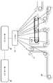
먼저, 본 예시적인 실시예에 따른 감시 대상의 장비(40)와 제1 처리 장치(10)를 장착하는 방법이 설명될 것이다. 도 4에 도시된 바와 같이, 감시 대상의 장비(40)는 벨트 컨베이어이다. 그 후, 제1 처리 장치(10)는 복수의 풀리(60)의 일부 또는 전부에 부착된다. 감시 대상의 장비(40) 및 제1 처리 장치(10)의 설치 위치들은 예들일 뿐이고, 다른 구성들이 채택될 수 있다는 점에 유의한다.First, a method of mounting the
다음으로, 제1 처리 장치(10) 및 제2 처리 장치(20)의 기능 블록도가 설명될 것이다.Next, functional block diagrams of the
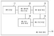
도 5는 제1 처리 장치(10)의 기능 블록도의 일례를 도시한다. 도시된 바와 같이, 제1 처리 장치(10)는 센서 유닛(11), 제1 데이터 처리 유닛(12), 제1 송신 유닛(13), 제1 모드 관리 유닛(14), 및 제1 수신 유닛(15)을 포함한다.5 shows an example of a functional block diagram of the
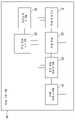
도 6은 제2 처리 장치(20)의 기능 블록도의 일례를 도시한다. 도시된 바와 같이, 제2 처리 장치(20)는 제2 수신 유닛(21), 판정 유닛(22), 제2 데이터 처리 유닛(23), 제2-2 송신 유닛(24), 제2 모드 관리 유닛(25), 및 제2-1 송신 유닛(26)을 포함한다.6 shows an example of a functional block diagram of the
본 예시적인 실시예의 감시 시스템은 제1 모드와 제2 모드를 갖는다. 감시 시스템은 제1 모드 또는 제2 모드에 있을 수 있고, 모드들은 교대로 스위칭될 수 있다.The monitoring system of this exemplary embodiment has a first mode and a second mode. The monitoring system may be in a first mode or a second mode, and the modes may be switched alternately.
제1 모드의 감시 시스템은 제2 모드에 비해 간단한 이상 판정을 행한다. 제1 모드에서, 복수의 제1 처리 장치(10) 각각은 이상이 있는지를 판정한다. 제2 모드에서의 감시 시스템은 제1 모드에서보다 더 상세한 이상 존재 판정을 행한다. 제2 모드에서, 제2 처리 장치(20)는 이상이 있는지를 판정한다.The monitoring system in the first mode performs a simpler abnormality determination than in the second mode. In the first mode, each of the plurality of
이하, 도 5 및 도 6의 기능 블록도들을 참조하여, "제1 모드에서의 제1 처리 장치(10) 및 제2 처리 장치(20)의 처리 내용들", "제2 모드에서의 제1 처리 장치(10) 및 제2 처리 장치(20)의 처리 내용들", 및 "모드 결정 방법"을 이 순서로 설명할 것이다.Hereinafter, with reference to the functional block diagrams of FIGS. 5 and 6 , “Processing contents of the
"제1 모드에서의 제1 처리 장치(10) 및 제2 처리 장치(20)의 처리 내용들"“Processing contents of the
먼저, 도 5를 참조하여, 제1 모드에서의 제1 처리 장치(10)의 처리 내용들에 대해서 설명할 것이다.First, with reference to FIG. 5 , processing contents of the
센서 유닛(11)은 제1 예시적인 실시예에서 설명된 진동 센서를 갖는다. 제1 모드 동안, 센서 유닛(11)은 진동 센서를 사용하여 측정을 계속한다.The
제1 데이터 처리 유닛(12)은 진동 센서의 측정 데이터에 기초하여, 감시 대상의 장비(40)에 이상이 있는지의 여부를 판정한다. 제1 모드 동안, 제1 데이터 처리 유닛(12)은 미리 결정된 시간마다 최신의 측정 데이터에 기초하여 상기 판정을 반복한다.The first
여기서, 제1 데이터 처리 유닛(12)에 의한 판정 방법에 대해서 설명할 것이다. 먼저, 감시 대상의 장비(40)에서 이상이 발생할 때 측정 데이터 또는 처리된 데이터에 나타나는 특징량(이하, "이상 특징량"이라고 지칭함)이 데이터베이스에 등록된다. 그 후, 측정 데이터 또는 처리된 데이터로부터 이상 특징량이 추출될 때, 제1 데이터 처리 유닛(12)은 감시 대상의 장비(40)에 이상이 있다고 판정한다. 한편, 측정 데이터 또는 처리된 데이터로부터 이상 특징량이 추출되지 않을 때, 제1 데이터 처리 유닛(12)은 감시 대상의 장비(40)에 이상이 없다고 판정한다.Here, the determination method by the first
이상 특징량은 특정 시점에서의 특징이거나, 시계열 변화의 특징일 수 있다. 또한, 이상 특징량은 한 타입의 값 또는 복수 타입의 값의 조합에 의해 정의될 수 있다.The abnormal characteristic quantity may be a characteristic at a specific time point or a characteristic of a time series change. In addition, the ideal feature quantity may be defined by one type of value or a combination of multiple types of values.
측정 데이터로부터 추출된 값으로서, 시간축에 대한 미리 결정된 축 방향의 진동 크기를 나타내는 파형에서 미리 결정된 시간 프레임에 나타나는 피크의 값, 해당 파형에서 미리 결정된 시간 프레임에 나타나는 복수의 피크의 값들의 산술 평균값, 산술 평균값에 대한 임의의 피크의 값의 크기(피크값/산술 평균값), 해당 파형에서 미리 결정된 시간 프레임에서 관찰된 진동들의 크기들의 적분값, 적분값에 대한 임의의 피크의 값의 크기(피크값/적분값), S/N비 등이 예시된다.a value extracted from the measurement data, a value of a peak appearing in a predetermined time frame in a waveform indicating a magnitude of vibration in a predetermined axial direction with respect to the time axis, an arithmetic mean value of values of a plurality of peaks appearing in a predetermined time frame in the waveform, The magnitude of the value of any peak with respect to the arithmetic mean value (peak value/arithmetic mean value), the integral value of the magnitudes of oscillations observed at a predetermined time frame in the corresponding waveform, the magnitude of the value of the arbitrary peak with respect to the integral value (peak value) /integral value), S/N ratio, and the like are exemplified.
또한, 처리된 데이터로서, 측정 데이터(시간축에 대한 미리 결정된 축 방향의 진동의 크기를 나타내는 파형)를 푸리에 변환함으로써 획득된 데이터가 예시된다. 그 후, 그러한 처리된 데이터로부터 추출된 값으로서, 고차파(high-order wave) 등의 특정 주파수에서의 값들의 산술 평균값, 부분 적분값 등이 예시된다. 또한, 처리된 데이터로서, 측정 데이터(시간축에 대한 미리 결정된 축 방향의 진동의 크기를 나타내는 파형)와 기준 데이터 사이의 차분 데이터 등이 예시된다.Further, as the processed data, data obtained by Fourier transforming measurement data (a waveform representing the magnitude of a vibration in a predetermined axial direction with respect to the time axis) is exemplified. Then, as a value extracted from such processed data, an arithmetic mean value, a partial integral value, etc. of values at a specific frequency, such as a high-order wave, are exemplified. Further, as the processed data, difference data and the like between measurement data (a waveform indicating the magnitude of a vibration in a predetermined axial direction with respect to the time axis) and reference data are exemplified.
제1 송신 유닛(13)은 제1 데이터 처리 유닛(12)의 판정 결과(감시 대상의 장비(40)에 이상이 있는지의 여부)를 제2 처리 장치(20)에 송신한다. 제1 모드 동안, 제1 송신 유닛(13)은 미리 결정된 시간마다 최신의 판정 결과를 반복적으로 송신한다.The
제1 송신 유닛(13)은 제1 모드 동안에 측정 데이터 및/또는 처리된 데이터를 제2 처리 장치(20)에 송신한다. 예를 들어, 제1 송신 유닛(13)은 미리 결정된 시간마다, 미리 결정된 시간 분의 측정 데이터 및/또는 처리된 데이터를 제2 처리 장치(20)에 송신한다.The
다음으로, 도 6을 참조하여, 제1 모드에서의 제2 처리 장치(20)의 처리 내용에 대해서 설명할 것이다.Next, with reference to FIG. 6, the process content of the
제2 수신 유닛(21)은 복수의 제1 처리 장치(10) 각각으로부터, 제1 처리 장치(10)의 판정 결과와, 측정 데이터 및/또는 처리된 데이터를 수신한다.The
판정 유닛(22)은 제1 처리 장치(10)의 판정 결과가 "감시 대상의 장비(40)에 이상있음" 또는 "감시 대상의 장비(40)에 이상없음"을 표시할지를 판정한다.The
제1 처리 장치(10)의 판정 결과가 이상없음을 나타낼 때, 제2-2 송신 유닛(24)은 제1 처리 장치(10)의 판정 결과를 제3 처리 장치(30)에 송신한다.When the determination result of the
한편, 제1 처리 장치(10)의 판정 결과가 이상있음을 나타낼 때, 제2 데이터 처리 유닛(23)은 제1 처리 장치(10)로부터 수신된 측정 데이터 또는 처리된 데이터에 기초하여, 감시 대상의 장비(40)에 이상이 있는지의 여부를 판정한다. 그 후, 제2-2 송신 유닛(24)은 제2 처리 장치(20)의 판정 결과를 제3 처리 장치(30)에 송신한다. 제2-2 송신 유닛(24)은, 제2 처리 장치(20)의 판정 결과 이외에, 제1 처리 장치(10)의 판정 결과를 제3 처리 장치(30)에 송신할 수 있다는 점에 유의한다.On the other hand, when the determination result of the
여기서, 제2 데이터 처리 유닛(23)에 의한 판정 방법에 대해서 설명할 것이다. 제2 데이터 처리 유닛(23)은 제1 데이터 처리 유닛(12)보다 높은 정밀도로 판정한다. 제2 데이터 처리 유닛(23)의 판정 방법은 조건을 만족시키도록 설계된다. 예를 들어, 제2 데이터 처리 유닛(23)은 제1 데이터 처리 유닛(12)에 의한 판정과 동일한 방법을 사용함으로써, 감시 대상의 장비(40)에 이상이 있는지의 여부를 판정할 수 있다. 이 경우, 제1 데이터 처리 유닛(12)보다 높은 정밀도로 판정을 구현하기 위한 다양한 수단이 있지만, 상이한 샘플링 레이트들과 같은 수단에 의해 구현될 수도 있다. 또한, 제2 데이터 처리 유닛(23)은 제1 데이터 처리 유닛(12)에 의한 판정과는 상이한 방법을 사용함으로써, 감시 대상의 장비(40)에 이상이 있는지의 여부를 판정할 수 있다. 구체적으로, 머신 러닝(예를 들어, 딥 러닝)의 기술을 사용하여, 감시 대상의 장비(40)에 이상이 있는지의 여부를 판정하는 방법이 예시된다.Here, the determination method by the second
"제2 모드에서의 제1 처리 장치(10) 및 제2 처리 장치(20)의 처리 내용"“Processing contents of the
먼저, 도 5를 참조하여, 제2 모드에서의 제1 처리 장치(10)의 처리 내용에 대해서 설명할 것이다.First, with reference to FIG. 5, the processing content of the
센서 유닛(11)은 제2 모드 동안 진동 센서에 의한 측정을 계속한다.The
제2 모드 동안, 제1 데이터 처리 유닛(12)은 감시 대상의 장비(40)에 이상이 있는지의 여부를 판정하지 않는다. 제1 데이터 처리 유닛(12)은 측정 데이터를 처리하고 처리된 데이터를 생성하는 프로세스를 실행할 수 있다는 점에 유의한다.During the second mode, the first
제1 송신 유닛(13)은 측정 데이터 및/또는 처리된 데이터를 제2 처리 장치(20)에 송신한다. 제2 모드 동안, 제1 송신 유닛(13)은 미리 결정된 시간마다, 미리 결정된 시간 분의 측정 데이터 및/또는 처리된 데이터를 제2 처리 장치(20)에 송신한다. 제2 모드 동안, 제1 송신 유닛(13)은 제1 처리 장치(10)의 판정 결과를 제2 처리 장치(20)에 송신하지 않는다는 점에 유의한다.The
다음으로, 도 6을 참조하여, 제2 모드에서의 제2 처리 장치(20)의 처리 내용에 대해서 설명할 것이다.Next, with reference to FIG. 6, the process content of the
제2 수신 유닛(21)은 복수의 제1 처리 장치(10) 각각으로부터 측정 데이터 및/또는 처리된 데이터를 수신한다. 제2 데이터 처리 유닛(23)은 측정 데이터 또는 처리된 데이터에 기초하여, 감시 대상의 장비(40)에 이상이 있는지의 여부를 판정한다. 그 후, 제2-2 송신 유닛(24)은 제2 처리 장치(20)의 판정 결과를 제3 처리 장치(30)에 송신한다. 제2 데이터 처리 유닛(23)에 의한 판정 방법은 "제1 모드에서의 제1 처리 장치(10) 및 제2 처리 장치(20)의 처리 내용"에서 설명한 것과 동일하다.The
"모드 결정 방법""How to determine the mode"
먼저, 도 6의 기능 블록도를 참조하여, 제2 처리 장치(20)의 처리 내용에 대해서 설명할 것이다.First, with reference to the functional block diagram of FIG. 6 , the processing contents of the
제2 모드 관리 유닛(25)은 제1 처리 장치(10)로부터 수신된 측정 데이터 및/또는 처리된 데이터에 기초하여, 감시 대상의 장비(40)의 상태를 추정한다. 그 후, 제2 모드 관리 유닛(25)은 감시 대상의 장비(40)의 추정 상태에 기초하여, 모드를 결정한다.The second
본 예시적인 실시예의 경우, 제2 모드 관리 유닛(25)은 측정 데이터 또는 처리된 데이터에 기초하여, 풀리(60)의 회전 속도를 추정한다. 예를 들어, 회전 속도는 측정 데이터 또는 처리된 데이터에 반복적으로 나타나는 특징의 출현 시간 간격(제1 출현으로부터 다음 출현까지의 시간 간격)을 풀리(60)가 1 회전하는데 필요한 시간으로서 설정함으로써 산출될 수 있다.In the case of this exemplary embodiment, the second
그 후, 제2 모드 관리 유닛(25)은, 추정된 회전 속도가 기준값 이하일 때, 제2 모드로서 결정한다. 한편, 제2 모드 관리 유닛(25)은, 추정된 회전 속도가 기준값보다 높을 때, 제1 모드로서 결정한다.Then, the second
전술한 바와 같이, 본 예시적인 실시예의 감시 시스템은 풀리(60)의 회전 상태(벨트 컨베이어의 속도)에 따라, 간단한 판정을 수행하기 위한 제1 모드와 상세한 판정을 수행하기 위한 제2 모드 사이의 스위칭을 수행할 수 있다.As described above, the monitoring system of this exemplary embodiment is configured to switch between a first mode for performing simple judgment and a second mode for performing detailed judgment, according to the rotational state of the pulley 60 (the speed of the belt conveyor). switching can be performed.
제2 처리 장치(20)는 현재 모드를 나타내는 정보를 그 자신의 저장 장치에 저장한다. 그 후, 제2 모드 관리 유닛(25)은 판정된 내용에 기초하여, 자신의 저장 장치에 기억되어 있는 현재 모드를 나타내는 정보를 업데이트한다.The
제1 모드와 제2 모드의 양쪽 모두에서, 제2 모드 관리 유닛(25)은 전술한 모드 판정 프로세스를 미리 결정된 시간 간격으로 반복 실행할 수 있다.In both the first mode and the second mode, the second
제2-1 송신 유닛(26)은 제2 모드 관리 유닛(25)에 의해 결정된 모드를 복수의 제1 처리 장치(10) 각각에 통지한다. 제2 모드 관리 유닛(25)에 의해 결정된 모드가 그 때의 현재 모드와 상이할 때(즉, 모드가 스위칭될 때), 제2-1 송신 유닛(26)은 결정된 모드를 복수의 제1 처리 장치(10) 각각에 통지할 수 있다는 점에 유의한다. 제2 모드 관리 유닛(25)에 의해 결정된 모드가 그 때의 현재 모드와 동일할 때(즉, 모드가 스위칭되지 않을 때), 복수의 제1 처리 장치(10) 각각은 결정된 모드를 통지받지 않을 수 있다.The 2-1
다음으로, 제1 처리 장치(10)의 처리 내용이 도 5의 기능 블록도를 참조하여 설명될 것이다.Next, the processing contents of the
제1 수신 유닛(15)은 제2 처리 장치(20)로부터 모드 통지를 수신한다. 제1 처리 장치(10)는 현재 모드를 나타내는 정보를 그 자신의 저장 장치에 저장한다. 그 후, 제1 모드 관리 유닛(14)은 제2 처리 장치(20)로부터 제1 수신 유닛(15)에 의해 수신된 통지 내용에 기초하여, 자신의 저장 장치에 기억되어 있는 현재 모드를 나타내는 정보를 갱신한다.The
다음으로, 제1 처리 장치(10)의 처리 흐름의 예가 도 7의 흐름도를 참조하여 설명될 것이다. 제1 처리 장치(10)의 센서 유닛(11)은 진동 센서에 의한 측정을 계속한다. 그 후, 제1 처리 장치(10)는 미리 결정된 시간마다 S11 내지 S14의 프로세스를 실행한다.Next, an example of the processing flow of the
S10에서, 제1 처리 장치(10)는 미리 결정된 프로세스를 실행하는 타이밍이 되었는지를 판정한다. 실행 타이밍이 되었을 때(S10에서 예), 제1 모드 관리 유닛(14)은 현재 모드를 체크한다(S11).In S10, the
현재 모드가 제1 모드(S11의 제1 모드)일 때, 제1 데이터 처리 유닛(12)은 측정 데이터 및/또는 처리된 데이터에 기초하여, 감시 대상의 장비(40)에 이상이 있는지의 여부를 판정한다(S12). 그 후, 제1 송신 유닛(13)은 제1 데이터 처리 유닛(12)의 판정 결과와 판정에 사용된 측정 데이터 및/또는 처리된 데이터를 제2 처리 장치(20)에 송신한다(S13).When the current mode is the first mode (the first mode of S11), the first
한편, 현재 모드가 제2 모드(S11의 제2 모드)일 때, 제1 송신 유닛(13)은 측정 데이터 및/또는 처리된 데이터를 제2 처리 장치(20)에 송신한다(S14).On the other hand, when the current mode is the second mode (the second mode of S11 ), the
그 후, 제1 처리 장치(10)는 처리를 종료하는 입력이 없는 한(S15에서 아니오), 동일한 프로세스를 계속한다.Thereafter, the
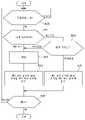
다음으로, 도 8의 흐름도를 참조하여, 제2 처리 장치(20)의 처리 흐름의 예에 대해서 설명할 것이다.Next, with reference to the flowchart of FIG. 8, the example of the process flow of the
제2 수신 유닛(21)이 제1 처리 장치(10)로부터 정보를 수신할 때(S30에서 예), 제2 모드 관리 유닛(25)은 현재 모드를 체크한다(S31).When the
현재 모드가 제1 모드(S31의 제1 모드)일 때, 제1 처리 장치(10)의 판정 결과는 제1 처리 장치(10)로부터 제2 수신 유닛(21)에 의해 수신된 정보에 포함된다. 판정 유닛(22)은 판정 결과가 "감시 대상의 장비(40)에 이상있음" 또는 "감시 대상의 장비(40)에 이상없음"을 나타낼 것인지를 판정한다.When the current mode is the first mode (the first mode of S31 ), the determination result of the
제1 처리 장치(10)의 판정 결과가 이상없음(S34에서 이상없음)을 나타낼 때, 제2-2 송신 유닛(24)은 제2 수신 유닛(21)에 의해 수신된 제1 처리 장치(10)의 판정 결과를 제3 처리 장치(30)에 송신한다(S35).When the determination result of the
한편, 제1 처리 장치(10)의 판정 결과가 이상있음(S34에서 이상있음)을 나타내거나, 또는 현재 모드가 제2 모드(S31에서 제2 모드)일 때, 제2 데이터 처리 유닛(23)은 제2 수신 유닛(21)에 의해 수신된 정보에 포함되는 측정 데이터 및/또는 처리된 데이터에 기초하여, 감시 대상의 장비(40)에 이상이 있는지의 여부를 판정한다(S32). 그 후, 제2-2 송신 유닛(24)은 제2 처리 장치(20)의 판정 결과를 제3 처리 장치(30)에 송신한다(S33).On the other hand, when the determination result of the
그 후, 제2 처리 장치(20)는 처리를 종료하는 입력이 없는 한(S36에서 아니오), 동일한 프로세스를 계속한다.Thereafter, the
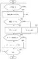
다음으로, 도 9의 흐름도를 참조하여, 제2 처리 장치(20)의 처리 흐름의 또 다른 예에 대해서 설명할 것이다.Next, another example of the processing flow of the
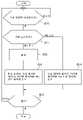
제2 수신 유닛(21)이 제1 처리 장치(10)로부터 측정 데이터 및/또는 처리된 데이터를 수신할 때(S50에서 예), 제2 모드 관리 유닛(25)은 풀리(60)의 회전 속도를 추정한다(S51). 그 후, 제2 모드 관리 유닛(25)은, 추정된 회전 속도가 기준값 이하일 때(S52에서 예), 제2 모드로서 결정한다(S53). 한편, 제2 모드 관리 유닛(25)은, 회전 속도가 기준값 이하가 아닐 때(S52에서 아니오), 제1 모드로서 결정한다(S54).When the
그 후, 제2 모드 관리 유닛(25)은, 새롭게 결정된 모드가 그 때의 현재 모드와 상이할 때, 즉 모드가 스위칭될 때(S55에서 예), 자신의 저장 장치에 기억되어 있는 현재 모드를 나타내는 정보를 업데이트한다(S56). 또한, 제2-1 송신 유닛(26)은 새롭게 결정된 모드를 복수의 제1 처리 장치(10)에 통지한다(S56). 한편, 새롭게 결정된 모드가 그 때의 현재 모드와 동일할 때, 즉 모드가 스위칭되지 않았을 때(S55에서 아니오), S56의 프로세스는 실행되지 않는다.Then, when the newly determined mode is different from the current mode at that time, that is, when the mode is switched (YES in S55), the second
그 후, 제2 처리 장치(20)는, 처리를 종료하는 입력이 없는 한(S57에서 아니오), 동일한 프로세스를 계속한다.Thereafter, the
전술한 바와 같이, 본 예시적인 실시예의 감시 시스템에 따르면, 제1 및 제2 예시적인 실시예의 감시 시스템들과 동일한 유익한 효과를 달성하는 것이 가능하다.As described above, according to the monitoring system of the present exemplary embodiment, it is possible to achieve the same beneficial effects as the monitoring systems of the first and second exemplary embodiments.
또한, 본 예시적인 실시예의 감시 시스템은 제2 처리 장치(20)에 의한 상세한 이상 유무 판정이 필요한 경우에만 수행될 수 있게 하고, 다른 경우에는, 제1 처리 장치(10)에 의한 간단한 이상 유무 판정이 수행될 수 있게 한다. 따라서, 항상 상세한 이상 유무 판정을 행하는 경우와 비교하여 감시 시스템의 처리 부하가 감소될 수 있다. 또한, 상세한 이상 유무 판정이 필요할 때 이루어지기 때문에, 신뢰성이 높은 감시 시스템이 실현될 수 있다.In addition, the monitoring system of the present exemplary embodiment enables detailed abnormality determination by the
필요한 경우는, 예를 들어, 제1 처리 장치(10)가 이상있음으로서 판정한 경우이다. 감시 대상의 장비(40)에 이상이 있을 때, 감시 대상의 장비(40)의 동작을 중지하는 것과 같은 조치들이 취해진다. 감시 대상의 장비(40)의 동작을 중지하는 것은, 많은 손해를 야기하기 때문에 최대한 회피하려는 액션이다. 따라서, 제2 처리 장치(20)는, 제1 처리 장치(10)에 의한 간단한 판정을 통해 이상있음으로서 판정될 때, 상세한 판정을 행하고, 제2 처리 장치(20)의 판정 결과를 출력한다. 따라서, 감시 시스템으로부터 출력된 "이상있음을 나타내는 판정 결과"의 신뢰도를 높일 수 있다. 그 결과, 잘못된 판정 "이상있음"으로 인해, 감시 대상의 장비(40)의 동작이 불필요하게 중지되는 불편함을 억제할 수 있다.A case where it is necessary is a case where it determines with the
또한, 필요한 경우는 예를 들어, 풀리(60)의 회전 속도는 기준값 이하일 수 있다. 이 경우, 감시 대상의 장비(40)로 전파되는 진동 에너지가 작기 때문에, 이상을 나타내는 특징을 간과할 위험이 있다. 이러한 경우, 제2 처리 장치(20)는 이상이 있는지의 여부에 관한 상세한 판정을 행함으로써, 작은 신호조차도 간과하지 않는 신뢰도가 높은 감시 시스템을 실현한다.In addition, if necessary, for example, the rotational speed of the
<제4 예시적인 실시예><Fourth exemplary embodiment>
본 예시적인 실시예의 감시 시스템은 제3 예시적인 실시예(도 3 참조)와 동일한 구성을 갖고, 제3 예시적인 실시예에서 설명하지 않은 부가 기능들을 추가로 갖는다.The monitoring system of this exemplary embodiment has the same configuration as that of the third exemplary embodiment (see Fig. 3), and additionally has additional functions not described in the third exemplary embodiment.
제1 처리 장치(10)의 기능 블록도의 예가 제3 예시적인 실시예에서와 같이, 도 5에 도시되어 있다. 제2 처리 장치(20)의 기능 블록도의 예가 도 10에 도시되어 있다. 본 예시적인 실시예의 제2 처리 장치(20)는 대조 유닛(27)을 갖는다는 점에서 제3 예시적인 실시예의 제2 처리 장치(20)와 상이하다. 도 5 및 도 10에 도시한 대조 유닛(27) 이외의 기능 유닛들은 제3 예시적인 실시예에서 설명한 구성들을 갖는다는 점에 유의한다.An example of a functional block diagram of the
도 5에 도시된 제1 처리 장치(10)의 제1 송신 유닛(13)은 제1 모드 동안 미리 결정된 타이밍에서 측정 데이터를 제2 처리 장치(20)에 송신한다. 제1 송신 유닛(13)은 측정 데이터를 미리 결정된 시간 간격으로 제2 처리 장치(20)에 반복적으로 송신한다.The
도 10에 도시된 제2 처리 장치(20)의 제2 수신 유닛(21)은 측정 데이터를 수신한다. 제2 데이터 처리 유닛(23)은 필요에 따라 측정 데이터를 처리하고, 측정 데이터 및/또는 처리된 데이터에 기초하여, 감시 대상의 장비(40)에 이상이 있는지의 여부를 판정한다.The
대조 유닛(27)은 제2 수신 유닛(21)이 수신한 제1 처리 장치(10)의 판정 결과를 제2 데이터 처리 유닛(23)의 판정 결과와 대조하고, 판정 결과들이 일치하는지 여부를 판정한다. 그 후, 제2-2 송신 유닛(24)은 대조 유닛(27)에 의해 수행된 대조 결과를 제3 처리 장치(30)에 송신한다.The
다음으로, 제1 처리 장치(10)의 처리 흐름의 예가 도 11의 흐름도를 참조하여 설명될 것이다. 제1 모드 동안, 제1 처리 장치(10)는 미리 결정된 시간마다 프로세스를 반복한다. 프로세스를 반복하기 위한 시간 간격은 도 7의 S11 내지 S14의 프로세스들을 반복하기 위한 시간 간격보다 크다.Next, an example of the processing flow of the
S20에서, 제1 처리 장치(10)는 미리 결정된 프로세스를 실행하는 타이밍이 되었는지를 판정한다. 실행 타이밍이 되었을 때(S20에서 예), 제1 송신 유닛(13)은 측정 데이터를 제2 처리 장치(20)에 송신한다(S21).In S20, the
그 후, 제1 처리 장치(10)는 프로세스를 종료하는 입력 또는 제2 모드로의 모드 변경이 없는 한(S22에서 아니오), 동일한 프로세스를 계속한다.Thereafter, the
다음으로, 도 12의 흐름도를 참조하여, 제2 처리 장치(20)의 처리 흐름의 예에 대해서 설명할 것이다. 제1 모드 동안, 제2 처리 장치(20)는 미리 결정된 시간마다 프로세스를 반복한다.Next, with reference to the flowchart of FIG. 12, the example of the process flow of the
제2 수신 유닛(21)이 제1 처리 장치(10)로부터 측정 데이터를 수신할 때(S40에서 예), 제2 데이터 처리 유닛(23)은 제2 수신 유닛(21)에 의해 수신된 측정 데이터에 기초하여, 감시 대상의 장비(40)에 이상이 있는지의 여부를 판정한다(S41).When the
다음으로, 대조 유닛(27)은 제1 처리 장치(10)의 판정 결과(예를 들어, 최신의 판정 결과)와 S41에서의 제2 데이터 처리 유닛(23)의 판정 결과를 대조한다(S42).Next, the
그 후, 제2-2 송신 유닛(24) 및 대조 유닛(27)에 의한 대조 결과(판정 결과들이 일치하는지의 여부)가 제3 처리 장치(30)에 송신된다(S43).Thereafter, the verification results (whether or not the determination results match) by the 2-2
그 후, 제2 처리 장치(20)는 처리를 종료하는 입력 또는 제2 모드로의 모드 변경이 없는 한(S44의 아니오), 동일한 프로세스를 계속한다.Thereafter, the
전술한 바와 같이, 본 예시적인 실시예의 감시 시스템에 따르면, 제1 내지 제3 예시적인 실시예의 감시 시스템들과 동일한 유익한 효과를 달성하는 것이 가능하다.As described above, according to the monitoring system of the present exemplary embodiment, it is possible to achieve the same beneficial effects as the monitoring systems of the first to third exemplary embodiments.
또한, 본 예시적인 실시예의 감시 시스템에 따르면, 제1 모드가 계속되고 제1 처리 장치(10)에 의해 수행되는 판정이 계속되는 동안에도, 제2 처리 장치(20)는 미리 결정된 시간마다 판정을 행하고, 제1 처리 장치(10)의 판정 결과와 제2 처리 장치(20)의 판정 결과의 대조 결과를 제3 처리 장치(30)에 송신할 수 있다. 이러한 방식으로, 정기적인 체크를 수행함으로써 제1 처리 장치(10)에서 발생한 이상을 검출하는 것이 가능하다.Further, according to the monitoring system of the present exemplary embodiment, even while the first mode continues and the judgment performed by the
상기 예시적인 실시예들의 일부 또는 전부는 다음의 부기들에도 열거될 수 있지만, 이에 한정되지 않는다.Some or all of the above exemplary embodiments may also be listed in, but not limited to, the following annexes.
1. 감시 시스템으로서,1. A surveillance system comprising:
감시 대상의 장비에 부착되고, 각각이 진동 센서를 갖는 복수의 제1 처리 장치;a plurality of first processing devices attached to the equipment to be monitored, each first processing device having a vibration sensor;
복수의 제1 처리 장치 각각과 케이블을 통해 통신하는 제2 처리 장치; 및a second processing unit in communication with each of the plurality of first processing units via a cable; and
제2 처리 장치와 무선으로 통신하는 제3 처리 장치를 포함하고,a third processing device in wireless communication with the second processing device;
제1 처리 장치와 제2 처리 장치 사이의 거리는 1m 이상 100m 이하이고,The distance between the first processing device and the second processing device is 1 m or more and 100 m or less,
제2 처리 장치와 제3 처리 장치 사이의 거리는 50m 이상이고,the distance between the second processing device and the third processing device is 50 m or more,
제2 처리 장치와 제3 처리 장치 간의 무선 통신 주파수는 400MHz 이상 5.3GHz 이하인 감시 시스템.A monitoring system in which the radio communication frequency between the second processing unit and the third processing unit is 400 MHz or more and 5.3 GHz or less.
2. 제1항에 있어서,2. according to clause 1,
진동 센서의 측정 데이터 및/또는 측정 데이터의 처리된 데이터는 제1 처리 장치와 제2 처리 장치 사이에서 송신되고,The measurement data of the vibration sensor and/or the processed data of the measurement data are transmitted between the first processing device and the second processing device,
제2 처리 장치와 제3 처리 장치 사이에서는, 진동 센서의 측정 데이터에 기초한 판정 결과가 송신되고, 측정 데이터 및 처리된 데이터는 송신되지 않는 감시 시스템.A monitoring system in which a determination result based on the measurement data of the vibration sensor is transmitted between the second processing apparatus and the third processing apparatus, and the measurement data and the processed data are not transmitted.
3. 제1항 또는 제2항에 있어서,3. Item 1 or 2,
감시 시스템은 복수의 모드를 가지고,The monitoring system has multiple modes,
제1 모드에서,In the first mode,
제1 처리 장치는the first processing device
진동 센서의 측정 데이터에 기초하여 장비에 이상이 있는지의 여부를 판정하고,It is determined whether there is an abnormality in the equipment based on the measurement data of the vibration sensor,
제1 처리 장치의 판정 결과, 및 측정 데이터 및/또는 측정 데이터의 처리된 데이터를 제2 처리 장치에 송신하고,sending the determination result of the first processing device and the measurement data and/or processed data of the measurement data to the second processing device;
제2 처리 장치는The second processing device is
제1 처리 장치의 판정 결과가 이상없음을 나타낼 때, 제1 처리 장치의 판정 결과를 제3 처리 장치에 송신하고,When the determination result of the first processing apparatus indicates that there is no abnormality, the determination result of the first processing apparatus is transmitted to the third processing apparatus;
제1 처리 장치의 판정 결과가 이상있음을 나타낼 때, 측정 데이터 또는 처리된 데이터에 기초하여 장비에 이상이 있는지의 여부를 판정하고, 제2 처리 장치의 판정 결과를 제3 처리 장치에 송신하는 감시 시스템.When the determination result of the first processing device indicates that there is an abnormality, it is determined whether there is an abnormality in the equipment based on the measured data or the processed data, and monitoring for transmitting the determination result of the second processing device to the third processing device system.
4. 제1항 내지 제3항 중 어느 한 항에 있어서,4. according to any one of items 1 to 3,
감시 시스템은 복수의 모드를 가지고,The monitoring system has multiple modes,
제2 모드에서,In the second mode,
제1 처리 장치는 진동 센서의 측정 데이터 또는 측정 데이터의 처리된 데이터를 제2 처리 장치에 송신하고,The first processing device sends the measurement data of the vibration sensor or the processed data of the measurement data to the second processing device,
제2 처리 장치는 측정 데이터 또는 처리된 데이터에 기초하여 장비에 이상이 있는지의 여부를 판정하고, 제2 처리 장치의 판정 결과를 제3 처리 장치에 송신하는 감시 시스템.The second processing device determines whether there is an abnormality in the equipment based on the measured data or the processed data, and transmits the determination result of the second processing device to the third processing device.
5. 제3항 또는 제4항에 있어서,5. Item 3 or 4,
제2 처리 장치는 모드를 결정하고 결정된 모드를 복수의 제1 처리 장치에 통지하는 감시 시스템.The second processing device determines a mode and a monitoring system for notifying the determined mode to the plurality of first processing devices.
6. 제5항에 있어서,6. according to claim 5,
제2 처리 장치는 측정 데이터 및/또는 처리된 데이터에 기초하여 장비의 상태를 추정하고, 추정된 장비의 상태에 기초하여 모드를 결정하는 감시 시스템.and the second processing device estimates a state of the equipment based on the measured data and/or the processed data, and determines a mode based on the estimated state of the equipment.
7. 제6항에 있어서,7. according to claim 6,
장비는 벨트 컨베이어이고,The equipment is a belt conveyor,
제1 처리 장치는 복수의 풀리의 일부 또는 전부에 부착되고,the first processing device is attached to some or all of the plurality of pulleys;
제2 처리 장치는 측정 데이터 또는 처리된 데이터에 기초하여 풀리의 회전 속도를 추정하고, 추정된 회전 속도가 기준값 이하일 때에는 제2 모드로서 결정하고, 추정된 회전 속도가 기준값보다 클 때에는 제1 모드로서 결정하는 감시 시스템.The second processing device estimates the rotational speed of the pulley based on the measured data or the processed data, and determines as the second mode when the estimated rotational speed is equal to or less than the reference value, and as the first mode when the estimated rotational speed is greater than the reference value. The monitoring system that decides.
8. 제1항 내지 제7항 중 어느 한 항에 있어서,8. according to any one of items 1 to 7,
제1 처리 장치는 미리 결정된 타이밍에 측정 데이터를 제2 처리 장치에 송신하고,the first processing device transmits the measurement data to the second processing device at a predetermined timing;
제2 처리 장치는 측정 데이터에 기초하여 장비에 이상이 있는지의 여부를 판정하고, 제2 처리 장치의 판정 결과를 제1 처리 장치의 판정 결과와 대조함으로써 제1 처리 장치의 상태를 판정하는 감시 시스템.The second processing device determines whether there is an abnormality in the equipment based on the measurement data, and a monitoring system that determines the state of the first processing device by comparing the determination result of the second processing device with the determination result of the first processing device .
9. 제1항 내지 제8항 중 어느 한 항에 있어서,9. according to any one of items 1 to 8,
장비는 벨트 컨베이어이고,The equipment is a belt conveyor,
제1 처리 장치는 복수의 풀리의 일부 또는 전부에 부착되는 감시 시스템.and the first processing device is attached to some or all of the plurality of pulleys.
10. 감시 방법으로서,10. A monitoring method comprising:
각각이 진동 센서를 갖는 복수의 제1 처리 장치를 감시 대상의 장비에 부착하는 단계;attaching a plurality of first processing devices each having a vibration sensor to the equipment to be monitored;
제2 처리 장치로 하여금 케이블을 통해 복수의 제1 처리 장치 각각과 통신하게 하는 단계- 제1 처리 장치와 제2 처리 장치 사이의 거리는 1m 이상 100m 이하임 -; 및causing the second processing device to communicate with each of the plurality of first processing devices via a cable, wherein a distance between the first processing device and the second processing device is greater than or equal to 1 m and less than or equal to 100 m; and
제3 처리 장치로 하여금 제2 처리 장치와 무선으로 통신하게 하는 단계- 제2 처리 장치와 제3 처리 장치 사이의 거리는 50m 이상이고, 무선 통신의 주파수는 400MHz 이상 5.3GHz 이하임 -를 포함하는 감시 방법.monitoring comprising the step of causing a third processing device to wirelessly communicate with the second processing device, a distance between the second processing device and the third processing device is 50 m or more, and a frequency of wireless communication is 400 MHz or more and 5.3 GHz or less Way.
이상, 예시적인 실시예들(및 예들)을 참조하여 본 발명을 설명했지만, 본 발명은 상기 예시적인 실시예들(및 예들)에 한정되지 않는다. 본 발명의 구성 및 세부사항들은, 본 발명의 범위 내에서 본 기술분야의 통상의 기술자가 이해할 수 있는 다양한 방식으로 변형될 수 있다.Although the present invention has been described above with reference to exemplary embodiments (and examples), the present invention is not limited to the above exemplary embodiments (and examples). The configuration and details of the present invention can be modified in various ways that can be understood by those skilled in the art within the scope of the present invention.
본 출원은 2018년 5월 31일자로 출원된 일본 특허 출원 제2018-104943호에 기초하여 우선권을 주장하며, 그 개시내용은 본 명세서에 그 전체가 포함된다.This application claims priority on the basis of Japanese Patent Application No. 2018-104943 filed on May 31, 2018, the disclosure of which is incorporated herein in its entirety.
Claims (10)
Translated fromKorean감시 대상의 장비에 부착되고, 각각이 진동 센서를 갖는 복수의 제1 처리 장치;
복수의 제1 처리 장치 각각과 케이블을 통해 통신하는 제2 처리 장치; 및
상기 제2 처리 장치와 무선으로 통신하는 제3 처리 장치를 포함하고,
상기 제1 처리 장치와 상기 제2 처리 장치 사이의 거리는 1m 이상 100m 이하이고,
상기 제2 처리 장치와 상기 제3 처리 장치 사이의 거리는 50m 이상이고,
상기 제2 처리 장치와 상기 제3 처리 장치 간의 무선 통신의 주파수는 400MHz 이상 5.3GHz 이하인 감시 시스템.A monitoring system comprising:
a plurality of first processing devices attached to the equipment to be monitored, each first processing device having a vibration sensor;
a second processing unit in communication with each of the plurality of first processing units via a cable; and
a third processing device in wireless communication with the second processing device;
The distance between the first processing device and the second processing device is 1 m or more and 100 m or less,
The distance between the second processing device and the third processing device is 50 m or more,
The frequency of wireless communication between the second processing unit and the third processing unit is 400 MHz or more and 5.3 GHz or less.
상기 진동 센서의 측정 데이터 및/또는 상기 측정 데이터의 처리된 데이터는 상기 제1 처리 장치와 상기 제2 처리 장치 사이에서 송신되고,
상기 제2 처리 장치와 상기 제3 처리 장치 사이에서는, 상기 진동 센서의 측정 데이터에 기초한 판정 결과가 송신되고, 상기 측정 데이터 및 상기 처리된 데이터는 송신되지 않는 감시 시스템.According to claim 1,
the measurement data of the vibration sensor and/or the processed data of the measurement data are transmitted between the first processing device and the second processing device,
A monitoring system in which a determination result based on the measurement data of the vibration sensor is transmitted between the second processing apparatus and the third processing apparatus, and the measurement data and the processed data are not transmitted.
상기 감시 시스템은 복수의 모드를 가지고,
제1 모드에서,
상기 제1 처리 장치는
상기 진동 센서의 측정 데이터에 기초하여 상기 장비에 이상이 있는지의 여부를 판정하고,
상기 제1 처리 장치의 판정 결과, 및 상기 측정 데이터 및/또는 상기 측정 데이터의 처리된 데이터를 상기 제2 처리 장치에 송신하고,
상기 제2 처리 장치는
상기 제1 처리 장치의 판정 결과가 이상없음을 나타낼 때, 상기 제1 처리 장치의 판정 결과를 상기 제3 처리 장치에 송신하고,
상기 제1 처리 장치의 판정 결과가 이상있음을 나타낼 때, 상기 측정 데이터 또는 상기 처리된 데이터에 기초하여 상기 장비에 이상이 있는지의 여부를 판정하고, 상기 제2 처리 장치의 판정 결과를 상기 제3 처리 장치에 송신하는 감시 시스템.3. The method of claim 1 or 2,
The monitoring system has a plurality of modes,
In the first mode,
The first processing device is
Determine whether there is an abnormality in the equipment based on the measurement data of the vibration sensor,
sending a determination result of the first processing device and the measurement data and/or processed data of the measurement data to the second processing device;
the second processing device
When the determination result of the first processing device indicates that there is no abnormality, the determination result of the first processing device is transmitted to the third processing device;
When the determination result of the first processing apparatus indicates that there is an abnormality, it is determined whether there is an abnormality in the equipment based on the measured data or the processed data, and the determination result of the second processing apparatus is set to the third A monitoring system that transmits to the processing unit.
상기 감시 시스템은 복수의 모드를 가지고,
제2 모드에서,
상기 제1 처리 장치는 상기 진동 센서의 측정 데이터 또는 상기 측정 데이터의 처리된 데이터를 상기 제2 처리 장치에 송신하고,
상기 제2 처리 장치는 상기 측정 데이터 또는 상기 처리된 데이터에 기초하여 상기 장비에 이상이 있는지의 여부를 판정하고, 상기 제2 처리 장치의 판정 결과를 상기 제3 처리 장치에 송신하는 감시 시스템.3. The method of claim 1 or 2,
The monitoring system has a plurality of modes,
In the second mode,
the first processing device transmits the measurement data of the vibration sensor or the processed data of the measurement data to the second processing device;
and the second processing device determines whether or not there is an abnormality in the equipment based on the measured data or the processed data, and transmits a determination result of the second processing device to the third processing device.
상기 제2 처리 장치는 모드를 결정하고 상기 결정된 모드를 상기 복수의 제1 처리 장치에 통지하는 감시 시스템.4. The method of claim 3,
and the second processing unit determines a mode and notifies the determined mode to the plurality of first processing units.
상기 제2 처리 장치는 상기 측정 데이터 및/또는 상기 처리된 데이터에 기초하여 상기 장비의 상태를 추정하고, 추정된 상기 장비의 상태에 기초하여 상기 모드를 결정하는 감시 시스템.6. The method of claim 5,
and the second processing device estimates the state of the equipment based on the measured data and/or the processed data, and determines the mode based on the estimated state of the equipment.
상기 감시 시스템은 복수의 모드를 가지고,
제1 모드에서,
상기 제1 처리 장치는
상기 진동 센서의 측정 데이터에 기초하여 상기 장비에 이상이 있는지의 여부를 판정하고,
상기 제1 처리 장치의 판정 결과, 및 상기 측정 데이터 및/또는 상기 측정 데이터의 처리된 데이터를 상기 제2 처리 장치에 송신하고,
상기 제2 처리 장치는
상기 제1 처리 장치의 판정 결과가 이상없음을 나타낼 때, 상기 제1 처리 장치의 판정 결과를 상기 제3 처리 장치에 송신하고,
상기 제1 처리 장치의 판정 결과가 이상있음을 나타낼 때, 상기 측정 데이터 또는 상기 처리된 데이터에 기초하여 상기 장비에 이상이 있는지의 여부를 판정하고, 상기 제2 처리 장치의 판정 결과를 상기 제3 처리 장치에 송신하고,
제2 모드에서,
상기 제1 처리 장치는 상기 진동 센서의 측정 데이터 또는 상기 측정 데이터의 처리된 데이터를 상기 제2 처리 장치에 송신하고,
상기 제2 처리 장치는 상기 측정 데이터 또는 상기 처리된 데이터에 기초하여 상기 장비에 이상이 있는지의 여부를 판정하고, 상기 제2 처리 장치의 판정 결과를 상기 제3 처리 장치에 송신하고,
상기 제2 처리 장치는 상기 측정 데이터 및/또는 상기 처리된 데이터에 기초하여 상기 장비의 상태를 추정하고, 추정된 상기 장비의 상태에 기초하여 모드를 결정하고, 상기 복수의 제1 처리 장치에 통지하고,
상기 장비는 벨트 컨베이어이고,
상기 제1 처리 장치는 복수의 풀리의 일부 또는 전부에 부착되고,
상기 제2 처리 장치는 상기 측정 데이터 또는 상기 처리된 데이터에 기초하여 풀리의 회전 속도를 추정하고, 추정된 상기 회전 속도가 기준값 이하일 때에는 상기 제2 모드로서 결정하고, 추정된 상기 회전 속도가 상기 기준값보다 클 때에는 상기 제1 모드로서 결정하는 감시 시스템.3. The method of claim 1 or 2,
The monitoring system has a plurality of modes,
In the first mode,
The first processing device is
Determine whether there is an abnormality in the equipment based on the measurement data of the vibration sensor,
sending a determination result of the first processing device and the measurement data and/or processed data of the measurement data to the second processing device;
the second processing device
When the determination result of the first processing device indicates that there is no abnormality, the determination result of the first processing device is transmitted to the third processing device;
When the determination result of the first processing apparatus indicates that there is an abnormality, it is determined whether there is an abnormality in the equipment based on the measured data or the processed data, and the determination result of the second processing apparatus is set to the third send to the processing unit;
In the second mode,
the first processing device transmits the measurement data of the vibration sensor or the processed data of the measurement data to the second processing device,
the second processing device determines whether there is an abnormality in the equipment based on the measured data or the processed data, and transmits a determination result of the second processing device to the third processing device;
the second processing unit estimates the state of the equipment based on the measured data and/or the processed data, determines a mode based on the estimated state of the equipment, and notifies the plurality of first processing units do,
The equipment is a belt conveyor,
the first processing device is attached to some or all of the plurality of pulleys;
The second processing device estimates the rotation speed of the pulley based on the measured data or the processed data, and determines as the second mode when the estimated rotation speed is equal to or less than a reference value, and the estimated rotation speed is the reference value A monitoring system that determines as the first mode when greater than.
상기 제1 처리 장치는 미리 결정된 타이밍에 상기 진동 센서의 측정 데이터를 상기 제2 처리 장치에 송신하고,
상기 제2 처리 장치는 상기 측정 데이터에 기초하여 상기 장비에 이상이 있는지의 여부를 판정하고, 상기 제2 처리 장치의 판정 결과를 상기 제1 처리 장치의 판정 결과와 대조함으로써 상기 제1 처리 장치의 상태를 판정하는 감시 시스템.3. The method of claim 1 or 2,
the first processing device transmits the measurement data of the vibration sensor to the second processing device at a predetermined timing;
The second processing device determines whether there is an abnormality in the equipment based on the measurement data, and compares the judgment result of the second processing device with the judgment result of the first processing device. A monitoring system that determines the condition.
상기 장비는 벨트 컨베이어이고,
상기 제1 처리 장치는 복수의 풀리의 일부 또는 전부에 부착되는 감시 시스템.3. The method of claim 1 or 2,
The equipment is a belt conveyor,
wherein the first processing device is attached to some or all of the plurality of pulleys.
각각이 진동 센서를 갖는 복수의 제1 처리 장치를 감시 대상의 장비에 부착하는 단계;
제2 처리 장치로 하여금 케이블을 통해 상기 복수의 제1 처리 장치 각각과 통신하게 하는 단계- 제1 처리 장치와 제2 처리 장치 사이의 거리는 1m 이상 100m 이하임 -; 및
제3 처리 장치로 하여금 상기 제2 처리 장치와 무선으로 통신하게 하는 단계- 상기 제2 처리 장치와 상기 제3 처리 장치 사이의 거리는 50m 이상이고, 상기 무선 통신의 주파수는 400MHz 이상 5.3GHz 이하임 -를 포함하는 감시 방법.
A monitoring method comprising:
attaching a plurality of first processing devices each having a vibration sensor to the equipment to be monitored;
causing a second processing device to communicate with each of the plurality of first processing devices via a cable, wherein a distance between the first processing device and the second processing device is greater than or equal to 1 m and less than or equal to 100 m; and
causing a third processing device to wirelessly communicate with the second processing device, a distance between the second processing device and the third processing device is greater than or equal to 50 m, and the frequency of the wireless communication is greater than or equal to 400 MHz and less than or equal to 5.3 GHz; A monitoring method comprising a.
Applications Claiming Priority (3)
| Application Number | Priority Date | Filing Date | Title |
|---|---|---|---|
| JP2018104943 | 2018-05-31 | ||
| JPJP-P-2018-104943 | 2018-05-31 | ||
| PCT/JP2019/007452WO2019230088A1 (en) | 2018-05-31 | 2019-02-27 | Monitoring system and monitoring method |
Publications (2)
| Publication Number | Publication Date |
|---|---|
| KR20210003841A KR20210003841A (en) | 2021-01-12 |
| KR102464187B1true KR102464187B1 (en) | 2022-11-07 |
Family
ID=68698063
Family Applications (1)
| Application Number | Title | Priority Date | Filing Date |
|---|---|---|---|
| KR1020207033479AActiveKR102464187B1 (en) | 2018-05-31 | 2019-02-27 | Surveillance Systems and Monitoring Methods |
Country Status (4)
| Country | Link |
|---|---|
| JP (1) | JP6981547B2 (en) |
| KR (1) | KR102464187B1 (en) |
| CN (1) | CN112204371B (en) |
| WO (1) | WO2019230088A1 (en) |
Families Citing this family (2)
| Publication number | Priority date | Publication date | Assignee | Title |
|---|---|---|---|---|
| WO2021140911A1 (en)* | 2020-01-08 | 2021-07-15 | 日本電気株式会社 | Vibration processing device, vibration processing method, and program |
| JP7322979B2 (en)* | 2020-02-03 | 2023-08-08 | 日本電気株式会社 | Vibration treatment device, vibration treatment method, and program |
Citations (4)
| Publication number | Priority date | Publication date | Assignee | Title |
|---|---|---|---|---|
| JP2008134182A (en) | 2006-11-29 | 2008-06-12 | Kyoto Institute Of Technology | Structure damage diagnostic system and method |
| JP2010208850A (en) | 2009-03-12 | 2010-09-24 | Nippon Steel Corp | Belt conveyor state monitoring system, data collecting device, and method and program for determining operating condition of belt conveyor |
| JP2014005139A (en) | 2012-06-27 | 2014-01-16 | Hitachi Ltd | Abnormality diagnosis method, abnormality diagnosis device, and passenger conveyor with abnormality diagnosis device |
| JP2016060556A (en) | 2014-09-16 | 2016-04-25 | Jfeスチール株式会社 | Abnormality detection method for belt conveyor |
Family Cites Families (12)
| Publication number | Priority date | Publication date | Assignee | Title |
|---|---|---|---|---|
| JP2007295020A (en)* | 2006-04-20 | 2007-11-08 | Toshiba Elevator Co Ltd | Remote monitoring system |
| KR100767065B1 (en)* | 2007-03-26 | 2007-10-17 | (주)홈시큐넷 | Remote probation system and method |
| ITBO20070756A1 (en)* | 2007-11-16 | 2009-05-17 | Filippo Bastianini | DEVICE FOR MONITORING THE HEALTH STATUS OF STRUCTURES |
| JP5161645B2 (en) | 2008-04-30 | 2013-03-13 | 株式会社東芝 | Time series data monitoring system |
| US8049637B2 (en)* | 2008-10-07 | 2011-11-01 | General Electric Company | Systems and methods for sensor-level machine monitoring |
| CN102589681A (en)* | 2012-04-05 | 2012-07-18 | 邓昌建 | High-reliability wireless vibration measurement method and device for monitoring state of rotating equipment |
| JP2015045584A (en)* | 2013-08-28 | 2015-03-12 | 大阪瓦斯株式会社 | Vibration signal acquisition device and vibration monitoring system |
| JP6407553B2 (en)* | 2014-04-16 | 2018-10-17 | Ntn株式会社 | Condition monitoring system |
| CN104023211B (en)* | 2014-06-12 | 2019-02-15 | 杭州潇楠科技有限公司 | Distributed monitoring system design method based on wireless network |
| US9921136B2 (en)* | 2014-08-05 | 2018-03-20 | 01dB-Metravib, Societe Par Actions Simplifee | Wireless collection and analysis of machine data |
| US9984551B2 (en)* | 2016-03-15 | 2018-05-29 | Ashworth Bros., Inc. | System and method for anticipating low-speed bearing failure |
| JP2018051721A (en)* | 2016-09-30 | 2018-04-05 | キヤノン株式会社 | Abnormality detection apparatus, abnormality detection method, and program |
- 2019
- 2019-02-27WOPCT/JP2019/007452patent/WO2019230088A1/ennot_activeCeased
- 2019-02-27JPJP2020521706Apatent/JP6981547B2/enactiveActive
- 2019-02-27KRKR1020207033479Apatent/KR102464187B1/enactiveActive
- 2019-02-27CNCN201980035065.0Apatent/CN112204371B/enactiveActive
Patent Citations (4)
| Publication number | Priority date | Publication date | Assignee | Title |
|---|---|---|---|---|
| JP2008134182A (en) | 2006-11-29 | 2008-06-12 | Kyoto Institute Of Technology | Structure damage diagnostic system and method |
| JP2010208850A (en) | 2009-03-12 | 2010-09-24 | Nippon Steel Corp | Belt conveyor state monitoring system, data collecting device, and method and program for determining operating condition of belt conveyor |
| JP2014005139A (en) | 2012-06-27 | 2014-01-16 | Hitachi Ltd | Abnormality diagnosis method, abnormality diagnosis device, and passenger conveyor with abnormality diagnosis device |
| JP2016060556A (en) | 2014-09-16 | 2016-04-25 | Jfeスチール株式会社 | Abnormality detection method for belt conveyor |
Also Published As
| Publication number | Publication date |
|---|---|
| KR20210003841A (en) | 2021-01-12 |
| CN112204371A (en) | 2021-01-08 |
| JPWO2019230088A1 (en) | 2021-05-20 |
| CN112204371B (en) | 2022-10-14 |
| WO2019230088A1 (en) | 2019-12-05 |
| JP6981547B2 (en) | 2021-12-15 |
Similar Documents
| Publication | Publication Date | Title |
|---|---|---|
| US11226607B2 (en) | Abnormality determination system, data transmitter-receptor, motor controller, and method for determining abnormality | |
| JP2021506701A (en) | Equipment and methods for monitoring conveyor systems | |
| KR102464187B1 (en) | Surveillance Systems and Monitoring Methods | |
| EP3605037A1 (en) | Information terminal and machine component diagnosis system | |
| JP6542096B2 (en) | Failure diagnosis system | |
| US20090045940A1 (en) | Wireless preprocessing sensor | |
| JP2016123027A (en) | Remote monitoring system and method for elevator apparatus | |
| US20230113659A1 (en) | System to evaluate structural behavior | |
| JP2022055558A (en) | Information transmitter, server, and information transmitting method | |
| US10077810B2 (en) | Sensor hub comprising a rotation encoder | |
| JP2009258063A (en) | Damage monitoring system and measuring device | |
| JP2018006583A (en) | Component mounting machine and component mounting system | |
| EP3417262B1 (en) | Predictive monitoring system and method | |
| JP2019185336A (en) | Monitoring system | |
| JPH09103007A (en) | Monitoring equipment for gas-insulated switchgear | |
| US20190367326A1 (en) | Non-intrusive elevator monitoring device | |
| CN110779721A (en) | Fault detection system | |
| US20250093866A1 (en) | Predictive maintenance system and an implementation method thereof | |
| US20230269127A1 (en) | Information processing device, information processing method, and information processing system | |
| US8290723B2 (en) | Apparatus for monitoring rotating components | |
| KR101045479B1 (en) | Multi factor measurement system | |
| JP2006170758A (en) | Remote monitoring method and remote monitoring system of electromagnetic environment | |
| JP2019021031A (en) | Sensor system, radio terminal device, management device, management method and management program | |
| KR102131242B1 (en) | Sensor for detecting vibration and system including the same | |
| JP6574708B2 (en) | Train data transmission method |
Legal Events
| Date | Code | Title | Description |
|---|---|---|---|
| PA0105 | International application | Patent event date:20201120 Patent event code:PA01051R01D Comment text:International Patent Application | |
| PA0201 | Request for examination | ||
| PG1501 | Laying open of application | ||
| E902 | Notification of reason for refusal | ||
| PE0902 | Notice of grounds for rejection | Comment text:Notification of reason for refusal Patent event date:20211229 Patent event code:PE09021S01D | |
| E701 | Decision to grant or registration of patent right | ||
| PE0701 | Decision of registration | Patent event code:PE07011S01D Comment text:Decision to Grant Registration Patent event date:20220930 | |
| GRNT | Written decision to grant | ||
| PR0701 | Registration of establishment | Comment text:Registration of Establishment Patent event date:20221102 Patent event code:PR07011E01D | |
| PR1002 | Payment of registration fee | Payment date:20221103 End annual number:3 Start annual number:1 | |
| PG1601 | Publication of registration |