KR102463695B1 - Vehicle input device - Google Patents
Vehicle input deviceDownload PDFInfo
- Publication number
- KR102463695B1 KR102463695B1KR1020160168796AKR20160168796AKR102463695B1KR 102463695 B1KR102463695 B1KR 102463695B1KR 1020160168796 AKR1020160168796 AKR 1020160168796AKR 20160168796 AKR20160168796 AKR 20160168796AKR 102463695 B1KR102463695 B1KR 102463695B1
- Authority
- KR
- South Korea
- Prior art keywords
- input
- light emitting
- light
- vehicle
- indicator
- Prior art date
- Legal status (The legal status is an assumption and is not a legal conclusion. Google has not performed a legal analysis and makes no representation as to the accuracy of the status listed.)
- Active
Links
Images


Classifications
- G—PHYSICS
- G06—COMPUTING OR CALCULATING; COUNTING
- G06F—ELECTRIC DIGITAL DATA PROCESSING
- G06F3/00—Input arrangements for transferring data to be processed into a form capable of being handled by the computer; Output arrangements for transferring data from processing unit to output unit, e.g. interface arrangements
- G06F3/01—Input arrangements or combined input and output arrangements for interaction between user and computer
- G06F3/03—Arrangements for converting the position or the displacement of a member into a coded form
- G06F3/041—Digitisers, e.g. for touch screens or touch pads, characterised by the transducing means
- G06F3/0412—Digitisers structurally integrated in a display
- B—PERFORMING OPERATIONS; TRANSPORTING
- B60—VEHICLES IN GENERAL
- B60K—ARRANGEMENT OR MOUNTING OF PROPULSION UNITS OR OF TRANSMISSIONS IN VEHICLES; ARRANGEMENT OR MOUNTING OF PLURAL DIVERSE PRIME-MOVERS IN VEHICLES; AUXILIARY DRIVES FOR VEHICLES; INSTRUMENTATION OR DASHBOARDS FOR VEHICLES; ARRANGEMENTS IN CONNECTION WITH COOLING, AIR INTAKE, GAS EXHAUST OR FUEL SUPPLY OF PROPULSION UNITS IN VEHICLES
- B60K35/00—Instruments specially adapted for vehicles; Arrangement of instruments in or on vehicles
- B60K35/10—Input arrangements, i.e. from user to vehicle, associated with vehicle functions or specially adapted therefor
- B—PERFORMING OPERATIONS; TRANSPORTING
- B60—VEHICLES IN GENERAL
- B60K—ARRANGEMENT OR MOUNTING OF PROPULSION UNITS OR OF TRANSMISSIONS IN VEHICLES; ARRANGEMENT OR MOUNTING OF PLURAL DIVERSE PRIME-MOVERS IN VEHICLES; AUXILIARY DRIVES FOR VEHICLES; INSTRUMENTATION OR DASHBOARDS FOR VEHICLES; ARRANGEMENTS IN CONNECTION WITH COOLING, AIR INTAKE, GAS EXHAUST OR FUEL SUPPLY OF PROPULSION UNITS IN VEHICLES
- B60K35/00—Instruments specially adapted for vehicles; Arrangement of instruments in or on vehicles
- B60K35/20—Output arrangements, i.e. from vehicle to user, associated with vehicle functions or specially adapted therefor
- B60K35/21—Output arrangements, i.e. from vehicle to user, associated with vehicle functions or specially adapted therefor using visual output, e.g. blinking lights or matrix displays
- B60K35/22—Display screens
- B—PERFORMING OPERATIONS; TRANSPORTING
- B60—VEHICLES IN GENERAL
- B60Q—ARRANGEMENT OF SIGNALLING OR LIGHTING DEVICES, THE MOUNTING OR SUPPORTING THEREOF OR CIRCUITS THEREFOR, FOR VEHICLES IN GENERAL
- B60Q3/00—Arrangement of lighting devices for vehicle interiors; Lighting devices specially adapted for vehicle interiors
- B60Q3/10—Arrangement of lighting devices for vehicle interiors; Lighting devices specially adapted for vehicle interiors for dashboards
- B60Q3/12—Arrangement of lighting devices for vehicle interiors; Lighting devices specially adapted for vehicle interiors for dashboards lighting onto the surface to be illuminated
- B—PERFORMING OPERATIONS; TRANSPORTING
- B60—VEHICLES IN GENERAL
- B60Q—ARRANGEMENT OF SIGNALLING OR LIGHTING DEVICES, THE MOUNTING OR SUPPORTING THEREOF OR CIRCUITS THEREFOR, FOR VEHICLES IN GENERAL
- B60Q3/00—Arrangement of lighting devices for vehicle interiors; Lighting devices specially adapted for vehicle interiors
- B60Q3/10—Arrangement of lighting devices for vehicle interiors; Lighting devices specially adapted for vehicle interiors for dashboards
- B60Q3/14—Arrangement of lighting devices for vehicle interiors; Lighting devices specially adapted for vehicle interiors for dashboards lighting through the surface to be illuminated
- G—PHYSICS
- G02—OPTICS
- G02B—OPTICAL ELEMENTS, SYSTEMS OR APPARATUS
- G02B27/00—Optical systems or apparatus not provided for by any of the groups G02B1/00 - G02B26/00, G02B30/00
- G02B27/10—Beam splitting or combining systems
- G02B27/14—Beam splitting or combining systems operating by reflection only
- G02B27/149—Beam splitting or combining systems operating by reflection only using crossed beamsplitting surfaces, e.g. cross-dichroic cubes or X-cubes
- G—PHYSICS
- G02—OPTICS
- G02B—OPTICAL ELEMENTS, SYSTEMS OR APPARATUS
- G02B6/00—Light guides; Structural details of arrangements comprising light guides and other optical elements, e.g. couplings
- G02B6/0001—Light guides; Structural details of arrangements comprising light guides and other optical elements, e.g. couplings specially adapted for lighting devices or systems
- G02B6/0011—Light guides; Structural details of arrangements comprising light guides and other optical elements, e.g. couplings specially adapted for lighting devices or systems the light guides being planar or of plate-like form
- G02B6/0066—Light guides; Structural details of arrangements comprising light guides and other optical elements, e.g. couplings specially adapted for lighting devices or systems the light guides being planar or of plate-like form characterised by the light source being coupled to the light guide
- G02B6/0068—Arrangements of plural sources, e.g. multi-colour light sources
- G—PHYSICS
- G06—COMPUTING OR CALCULATING; COUNTING
- G06F—ELECTRIC DIGITAL DATA PROCESSING
- G06F3/00—Input arrangements for transferring data to be processed into a form capable of being handled by the computer; Output arrangements for transferring data from processing unit to output unit, e.g. interface arrangements
- G06F3/01—Input arrangements or combined input and output arrangements for interaction between user and computer
- G06F3/03—Arrangements for converting the position or the displacement of a member into a coded form
- G06F3/041—Digitisers, e.g. for touch screens or touch pads, characterised by the transducing means
- G06F3/044—Digitisers, e.g. for touch screens or touch pads, characterised by the transducing means by capacitive means
- B60K2350/1024—
- B—PERFORMING OPERATIONS; TRANSPORTING
- B60—VEHICLES IN GENERAL
- B60K—ARRANGEMENT OR MOUNTING OF PROPULSION UNITS OR OF TRANSMISSIONS IN VEHICLES; ARRANGEMENT OR MOUNTING OF PLURAL DIVERSE PRIME-MOVERS IN VEHICLES; AUXILIARY DRIVES FOR VEHICLES; INSTRUMENTATION OR DASHBOARDS FOR VEHICLES; ARRANGEMENTS IN CONNECTION WITH COOLING, AIR INTAKE, GAS EXHAUST OR FUEL SUPPLY OF PROPULSION UNITS IN VEHICLES
- B60K2360/00—Indexing scheme associated with groups B60K35/00 or B60K37/00 relating to details of instruments or dashboards
- B60K2360/143—Touch sensitive instrument input devices
- B60K2360/1438—Touch screens
- B—PERFORMING OPERATIONS; TRANSPORTING
- B60—VEHICLES IN GENERAL
- B60K—ARRANGEMENT OR MOUNTING OF PROPULSION UNITS OR OF TRANSMISSIONS IN VEHICLES; ARRANGEMENT OR MOUNTING OF PLURAL DIVERSE PRIME-MOVERS IN VEHICLES; AUXILIARY DRIVES FOR VEHICLES; INSTRUMENTATION OR DASHBOARDS FOR VEHICLES; ARRANGEMENTS IN CONNECTION WITH COOLING, AIR INTAKE, GAS EXHAUST OR FUEL SUPPLY OF PROPULSION UNITS IN VEHICLES
- B60K2360/00—Indexing scheme associated with groups B60K35/00 or B60K37/00 relating to details of instruments or dashboards
- B60K2360/20—Optical features of instruments
- B60K2360/33—Illumination features
- B60K2360/34—Backlit symbols
- B—PERFORMING OPERATIONS; TRANSPORTING
- B60—VEHICLES IN GENERAL
- B60K—ARRANGEMENT OR MOUNTING OF PROPULSION UNITS OR OF TRANSMISSIONS IN VEHICLES; ARRANGEMENT OR MOUNTING OF PLURAL DIVERSE PRIME-MOVERS IN VEHICLES; AUXILIARY DRIVES FOR VEHICLES; INSTRUMENTATION OR DASHBOARDS FOR VEHICLES; ARRANGEMENTS IN CONNECTION WITH COOLING, AIR INTAKE, GAS EXHAUST OR FUEL SUPPLY OF PROPULSION UNITS IN VEHICLES
- B60K2360/00—Indexing scheme associated with groups B60K35/00 or B60K37/00 relating to details of instruments or dashboards
- B60K2360/77—Instrument locations other than the dashboard
- B60K2360/774—Instrument locations other than the dashboard on or in the centre console
- B—PERFORMING OPERATIONS; TRANSPORTING
- B60—VEHICLES IN GENERAL
- B60K—ARRANGEMENT OR MOUNTING OF PROPULSION UNITS OR OF TRANSMISSIONS IN VEHICLES; ARRANGEMENT OR MOUNTING OF PLURAL DIVERSE PRIME-MOVERS IN VEHICLES; AUXILIARY DRIVES FOR VEHICLES; INSTRUMENTATION OR DASHBOARDS FOR VEHICLES; ARRANGEMENTS IN CONNECTION WITH COOLING, AIR INTAKE, GAS EXHAUST OR FUEL SUPPLY OF PROPULSION UNITS IN VEHICLES
- B60K35/00—Instruments specially adapted for vehicles; Arrangement of instruments in or on vehicles
- B60K35/20—Output arrangements, i.e. from vehicle to user, associated with vehicle functions or specially adapted therefor
- B60K35/28—Output arrangements, i.e. from vehicle to user, associated with vehicle functions or specially adapted therefor characterised by the type of the output information, e.g. video entertainment or vehicle dynamics information; characterised by the purpose of the output information, e.g. for attracting the attention of the driver
- B—PERFORMING OPERATIONS; TRANSPORTING
- B60—VEHICLES IN GENERAL
- B60K—ARRANGEMENT OR MOUNTING OF PROPULSION UNITS OR OF TRANSMISSIONS IN VEHICLES; ARRANGEMENT OR MOUNTING OF PLURAL DIVERSE PRIME-MOVERS IN VEHICLES; AUXILIARY DRIVES FOR VEHICLES; INSTRUMENTATION OR DASHBOARDS FOR VEHICLES; ARRANGEMENTS IN CONNECTION WITH COOLING, AIR INTAKE, GAS EXHAUST OR FUEL SUPPLY OF PROPULSION UNITS IN VEHICLES
- B60K35/00—Instruments specially adapted for vehicles; Arrangement of instruments in or on vehicles
- B60K35/60—Instruments characterised by their location or relative disposition in or on vehicles
- F—MECHANICAL ENGINEERING; LIGHTING; HEATING; WEAPONS; BLASTING
- F21—LIGHTING
- F21W—INDEXING SCHEME ASSOCIATED WITH SUBCLASSES F21K, F21L, F21S and F21V, RELATING TO USES OR APPLICATIONS OF LIGHTING DEVICES OR SYSTEMS
- F21W2107/00—Use or application of lighting devices on or in particular types of vehicles
- G—PHYSICS
- G02—OPTICS
- G02B—OPTICAL ELEMENTS, SYSTEMS OR APPARATUS
- G02B6/00—Light guides; Structural details of arrangements comprising light guides and other optical elements, e.g. couplings
- G02B6/0001—Light guides; Structural details of arrangements comprising light guides and other optical elements, e.g. couplings specially adapted for lighting devices or systems
- G02B6/0011—Light guides; Structural details of arrangements comprising light guides and other optical elements, e.g. couplings specially adapted for lighting devices or systems the light guides being planar or of plate-like form
Landscapes
- Engineering & Computer Science (AREA)
- Mechanical Engineering (AREA)
- Physics & Mathematics (AREA)
- Combustion & Propulsion (AREA)
- Transportation (AREA)
- Chemical & Material Sciences (AREA)
- Theoretical Computer Science (AREA)
- General Engineering & Computer Science (AREA)
- General Physics & Mathematics (AREA)
- Human Computer Interaction (AREA)
- Optics & Photonics (AREA)
- Instrument Panels (AREA)
- Switches That Are Operated By Magnetic Or Electric Fields (AREA)
- Switch Cases, Indication, And Locking (AREA)
- Illuminated Signs And Luminous Advertising (AREA)
Abstract
Translated fromKoreanDescription
Translated fromKorean본 발명은 차량의 센터페시아 등에 적용되는 차량용 입력기구에 관한 것으로, 보다 상세하게는 디스플레이영역 및 입력영역이 동일체로 구현됨으로써 디자인자유도가 향상된 차량용 입력기구에 관한 것이다.The present invention relates to an input device for a vehicle applied to a center fascia of a vehicle, and more particularly, to an input device for a vehicle with improved design freedom by implementing a display area and an input area as the same body.
일반적으로, 차량에는 운전자 또는 탑승자의 편의성을 높이기 위한 에어컨, 히터, 오디오, 네비게이션 등과 같은 다양한 장치가 설치되어 있다. 에어컨, 히터, 오디오, 네비게이션 등과 같은 장치의 조작을 위한 입력기구가 차량의 센터페시아, 대시보드, 콘솔박스 등에 설치될 수 있다.In general, various devices such as an air conditioner, a heater, an audio system, and a navigation system are installed in a vehicle to increase the convenience of a driver or a passenger. An input device for operating a device such as an air conditioner, a heater, an audio device, or a navigation device may be installed in a center fascia, a dashboard, a console box, and the like of the vehicle.
이러한 종래의 차량용 입력기구는 푸시타입으로 구성된 복수의 노브를 가지고, 이로 인해 그 조립부품수가 상대적으로 많이 소요되고, 이로 인해 전체적인 조립구조가 복잡할 뿐만 아니라 그 중량이 상대적으로 크게 이루어지는 단점이 있었다.Such a conventional input device for a vehicle has a plurality of knobs composed of a push type, and thus the number of assembly parts thereof is relatively large, and thus the overall assembly structure is complicated and the weight thereof is relatively large.
차량의 센터페시아 등에는 차량의 운전조건, 네이게이션 정보 등을 표시하는 디스플레이가 마련되고, 입력기구는 디스플레이에 대해 독립적으로 구성됨에 따라 디스플레이와 입력기구 사이에는 경계라인이 형성될 수 있다.A display for displaying driving conditions and navigation information of the vehicle is provided on the center fascia of the vehicle, and the input device is configured independently of the display, so that a boundary line may be formed between the display and the input device.
이와 같이, 종래에는 입력기구와 디스플레이 사이에 경계라인이 형성됨에 따라 디자인 자유도가 저하될 수 있는 단점이 있었다.As described above, as a boundary line is formed between the input device and the display in the related art, there is a disadvantage that the degree of freedom in design may be reduced.
본 발명은 상기와 같은 점을 고려하여 안출한 것으로, 터치방식의 입력구조를 구현함과 더불어, 디스플레이영역 및 입력영역가 동일체로 구성됨으로써 디자인자유도 및 조립성을 향상시킬 수 있는 차량용 입력기구를 제공하는 데 그 목적이 있다.The present invention has been devised in consideration of the above points, and provides an input device for a vehicle capable of improving design freedom and assembling property by realizing a touch-type input structure and comprising a display area and an input area as the same body It is intended to
상기와 같은 목적을 달성하기 위한 본 발명의 일 측면에 따른 차량용 입력기구는,A vehicle input device according to an aspect of the present invention for achieving the above object,
디스플레이영역과 입력영역을 가진 바디; 및a body having a display area and an input area; and
상기 입력영역의 하부에 설치된 터치조립체;를 포함하고,Including; a touch assembly installed under the input area;
상기 입력영역에는 하나 이상의 입력엘리먼트 및 하나 이상의 인디케이터가 형성될 수 있다.One or more input elements and one or more indicators may be formed in the input area.
상기 터치조립체는 하나 이상의 터치센서가 설치된 인쇄회로기판과, 상기 인쇄회로기판의 상부에 배치된 조명유닛을 포함하고, 상기 터치센서는 상기 입력엘리먼트에 대응하는 위치에 배치될 수 있다.The touch assembly may include a printed circuit board on which one or more touch sensors are installed, and a lighting unit disposed on the printed circuit board, and the touch sensor may be disposed at a position corresponding to the input element.
상기 터치센서는 정전용량 터치센서일 수 있다.The touch sensor may be a capacitive touch sensor.
상기 조명유닛은 복수의 발광소자 및 복수의 발광소자를 지지하는 지지부재를 포함할 수 있다.The lighting unit may include a plurality of light emitting devices and a support member supporting the plurality of light emitting devices.
상기 지지부재는 하나 이상의 개구를 가지고, 상기 개구에는 제1발광소자 및 제2발광소자가 개별적으로 설치될 수 있다.The support member may have one or more openings, and a first light emitting element and a second light emitting element may be separately installed in the opening.
상기 제1발광소자는 상기 입력엘리먼트 측으로 빛을 조사하고, 상기 제2발광소자는 상기 인디케이터 측으로 빛을 조사하도록 구성될 수 있다.The first light emitting device may be configured to emit light toward the input element, and the second light emitting device may be configured to emit light toward the indicator.
상기 개구에는 제1도광판 및 제2도광판이 개별적으로 설치되며, 상기 제1도광판은 상기 제1발광소자의 빛을 상기 입력엘리먼트 측으로 가이드하고, 상기 제2도광판은 상기 제2발광소자의 빛을 상기 인디케이터 측으로 가이드하도록 구성될 수 있다.A first light guide plate and a second light guide plate are separately installed in the opening, the first light guide plate guides the light of the first light emitting device toward the input element, and the second light guide plate transmits the light of the second light emitting device to the It may be configured to guide toward the indicator.
상기 조명유닛의 상부에는 필름이 배치되며, 상기 필름은 상기 입력엘리먼트 및 상기 인디케이터에 대응하는 위치에 형성된 복수의 투광부를 가질 수 있다.A film is disposed on the lighting unit, and the film may have a plurality of light-transmitting parts formed at positions corresponding to the input element and the indicator.
상기 입력엘리먼트 및 상기 인디케이터는 사출에 의해 상기 바디의 입력영역에 전사인쇄될 수 있다.The input element and the indicator may be transferred and printed on the input area of the body by injection.
상기 입력엘리먼트 및 상기 인디케이터의 상면에는 하프미러가 배치될 수 있다.A half mirror may be disposed on upper surfaces of the input element and the indicator.
본 발명의 실시예에 따른 차량용 입력기구는 터치방식의 입력구조로 구현됨과 더불어, 디스플레이영역 및 입력영역가 동일체로 구성됨으로써 디자인자유도 및 조립성을 향상시킬 수 있는 장점이 있다.The input device for a vehicle according to an embodiment of the present invention is implemented with a touch-type input structure, and has an advantage in that the display area and the input area are configured as the same body, thereby improving design freedom and assembly.
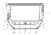
도 1은 본 발명의 실시예에 따른 차량용 입력기구를 도시한 정면도이다.
도 2는 도 1의 A-A선을 따라 도시한 단면도이다.
도 3은 도 2의 화살표 B 부분을 확대하여 도시한 도면이다.
도 4는 본 발명의 실시예에 따른 차량용 입력기구의 입력엘리먼트 및 인디케이터가 필름의 표면에 형성된 상태를 도시한 도면이다.
도 5는 본 발명의 실시예에 따른 차량용 입력기구의 입력엘리먼트 및 인디케이터가 바디의 입력영역에 형성되는 단계를 도시한 도면이다.
도 6은 본 발명의 실시예에 따른 차량용 입력기구의 입력엘리먼트 및 인디케이터가 바디의 입력영역에 형성되는 단계를 도시한 도면이다.
도 7은 본 발명의 실시예에 따른 차량용 입력기구의 입력엘리먼트 및 인디케이터가 바디의 입력영역에 형성되는 단계를 도시한 도면이다.
도 8은 본 발명의 실시예에 따른 차량용 입력기구의 제어블록도를 도시한 도면이다.1 is a front view illustrating an input device for a vehicle according to an embodiment of the present invention.
FIG. 2 is a cross-sectional view taken along line AA of FIG. 1 .
FIG. 3 is an enlarged view of an arrow B portion of FIG. 2 .
4 is a view showing a state in which the input element and the indicator of the input device for a vehicle according to an embodiment of the present invention are formed on the surface of the film.
5 is a diagram illustrating a step in which an input element and an indicator of an input device for a vehicle are formed in an input area of a body according to an embodiment of the present invention.
6 is a diagram illustrating a step in which an input element and an indicator of an input device for a vehicle are formed in an input area of a body according to an embodiment of the present invention.
7 is a diagram illustrating a step in which an input element and an indicator of an input device for a vehicle are formed in an input area of a body according to an embodiment of the present invention.
8 is a diagram illustrating a control block diagram of an input device for a vehicle according to an embodiment of the present invention.
이하, 본 발명의 바람직한 실시예를 첨부된 도면을 참조하여 상세히 설명한다. 참고로, 본 발명을 설명하는 데 참조하는 도면에 도시된 구성요소의 크기, 선의 두께 등은 이해의 편의상 다소 과장되게 표현되어 있을 수 있다. 또, 본 발명의 설명에 사용되는 용어들은 본 발명에서의 기능을 고려하여 정의한 것이므로 사용자, 운용자 의도, 관례 등에 따라 달라질 수 있다. 따라서, 이 용어에 대한 정의는 본 명세서의 전반에 걸친 내용을 토대로 내리는 것이 마땅하겠다.Hereinafter, preferred embodiments of the present invention will be described in detail with reference to the accompanying drawings. For reference, sizes of components, thicknesses of lines, etc. shown in the drawings referenced to describe the present invention may be expressed somewhat exaggeratedly for convenience of understanding. In addition, the terms used in the description of the present invention are defined in consideration of functions in the present invention, and thus may vary according to user, operator intention, custom, and the like. Therefore, the definition of this term should be made based on the content throughout the present specification.
도 1을 참조하면, 본 발명의 실시예에 따른 차량용 입력기구(10)는 디스플레이영역(12)과 입력영역(13)을 가진 바디(11)와, 입력영역(13)의 하부에 설치된 터치조립체(20)를 포함할 수 있다.Referring to FIG. 1 , a vehicle input device 10 according to an embodiment of the present invention includes a
바디(11)는 전체적으로 빛을 투광할 수 있는 투광성을 가진 수지 재질로 이루어질 수 있다.The
바디(11)는 다양한 정보를 표시하는 디스플레이영역(12)과, 디스플레이영역(12)의 일측에 배치된 입력영역(13)을 가질 수 있다.The
디스플레이영역(12)은 차량의 운전조건, 차량의 상태, 네비게이션 정보, 오디오 정보, 비디오 정보 등과 같은 다양한 정보를 표시하도록 구성될 수 있다.The
이러한 디스플레이영역(12)의 하부에는 디스플레이패널, 디스플레이 구동모듈 등이 설치될 수 있다.A display panel, a display driving module, etc. may be installed under the
도 1 및 도 2에 도시된 바와 같이, 바디(11)의 입력영역(13)에는 사용자의 터치가 입력되는 하나 이상의 입력엘리먼트(31, input element) 및 차량의 조건 등을 나타내는 하나 이상의 인디케이터(35, indicator)가 형성될 수 있다. 입력엘리먼트(31) 및 인디케이터(35)는 문자, 숫자, 기호 등과 같은 다양한 심볼로 표시될 수 있다.1 and 2 , in the
입력엘리먼트(31) 및 인디케이터(35)는 후술하는 터치조립체(20)의 발광소자(23a, 23b)로부터 빛을 투광할 수 있는 투광성 색상으로 이루어질 수 있다. 각 입력엘리먼트(31)의 주변 및 각 인디케이터(35)의 주변에는 바탕부(32)가 형성될 수 있고, 바탕부(32)는 블랙 등과 같이 빛을 투광시키지 못하는 비투광성 색상으로 이루어질 수 있다.The
본 발명의 실시예에 따르면, 복수의 입력엘리먼트(31) 및 복수의 인디케이터(35)가 바디(11)의 입력영역(13)의 표면에 사출(Molding) 등에 의해 전사인쇄방식(transfer printing)으로 형성될 수도 있다.According to an embodiment of the present invention, the plurality of
도 2를 참조하면, 바디(11)의 입력영역(13)의 하부에는 터치조립체(20)가 설치될 수 있고, 터치조립체(20)는 커버(29)에 의해 지지될 수 있으며, 커버(29)는 체결구 등을 통해 바디(11)의 하면에 분리가능하게 결합될 수 있다.Referring to FIG. 2 , the
도 3을 참조하면, 터치조립체(20)는 인쇄회로기판(21)과, 인쇄회로기판(21)의 상부에 배치된 조명유닛(25)과, 조명유닛(25)의 상부에 배치된 필름(27)을 포함할 수 있다.Referring to FIG. 3 , the
인쇄회로기판(21)의 상면에는 복수의 터치센서(22)가 설치될 수 있고, 복수의 터치센서(22)는 복수의 입력엘리먼트(31)와 동일한 갯수로 이루어질 수 있다. 복수의 터치센서(22)는 복수의 입력엘리먼트(31)에 대응하는 위치에 설치될 수 있다.A plurality of
본 발명의 실시예에 따르면, 터치센서(22)는 사용자의 터치에 의한 정전용량의 변화를 감지하는 정전용량 터치센서(capacitive touch sensor)일 수 있다.According to an embodiment of the present invention, the
조명유닛(25)은 복수의 발광소자(23a, 23b) 및 복수의 발광소자(23a, 23b)를 지지하는 지지부재(26)를 포함하고, 지지부재(26)는 복수의 개구(26a)를 가질 수 있다.The
복수의 개구(26a)는 복수의 입력엘리먼트(31) 및 복수의 인디케이터(35)와 동일한 갯수로 이루어질 수 있다. 복수의 개구(26a)는 복수의 입력엘리먼트(31) 및 복수의 인디케이터(35)에 대응하는 위치에 설치될 수 있다.The plurality of
복수의 개구(26a)에는 제1발광소자(23a) 및 제2발광소자(23b)가 개별적으로 설치될 수 있다. 각 제1발광소자(23a)는 각 입력엘리먼트(31) 측으로 빛을 조사하도록 구성되고, 각 제2발광소자(23b)는 각 인디케이터(35) 측으로 빛을 조사하도록 구성될 수 있다.The first
본 발명의 실시예에 따르면, 각 발광소자(23a 23b)는 LED일 수 있다.According to an embodiment of the present invention, each
본 발명의 실시예에 따르면, 복수의 개구(26a)에는 복수의 제1도광판(24a) 및 복수의 제2도광판(24b)이 개별적으로 설치될 수 있다.According to an embodiment of the present invention, a plurality of first
각 제1도광판(24a)은 각 제1발광소자(23a)의 측면에 개별적으로 인접하도록 배치될 수 있으며, 각 제1도광판(24a)은 각 제1발광소자(23a)의 빛을 입력엘리먼트(31) 측으로 개별적으로 가이드하도록 구성될 수 있다. 일 예에 따르면, 각 제1도광판(24a)의 수직축선이 각 입력엘리먼트(31)의 수직축선과 일치하도록 배치될 수 있다.Each of the first
각 제2도광판(24b)은 제2발광소자(23b)의 측면에 개별적으로 인접하게 배치될 수 있으며, 각 제2도광판(24b)은 각 제2발광소자(23b)의 빛을 인디케이터(35) 측으로 개별적으로 가이드하도록 구성될 수 있다. 일 예에 따르면, 각 제2도광판(24b)의 수직축선이 각 인디케이터(35)의 수직축선과 일치하도록 배치될 수 있다.Each of the second
이와 같이, 본 발명에 의하면 지지부재(26)의 개구(26a)에 발광소자(23a, 23b) 및 도광판(24a, 24b)이 개별적으로 수용됨으로써 발광소자(23a, 23b) 및 도광판(24a, 24b)의 위치가 고정적으로 유지될 뿐만 아니라 인접한 발광소자(23a, 23b)들이 서로 간에 격리될 수 있으므로 인접한 발광소자(23a, 23b)에서 조사되는 빛이 간섭됨을 효과적으로 방지할 수 있다.As described above, according to the present invention, since the
필름(27)은 복수의 입력엘리먼트(31) 및 복수의 인디케이터(35)에 대응하는 위치에 형성된 복수의 투광부(27a)를 가질 수 있다.The
각 투광부(27a)의 주변 및 투광부(27a)들 사이에 비투광부(27b)가 형성될 수 있고, 비투광부(27b)는 입력엘리먼트(31)의 주변 및 입력엘리먼트(31)들 사이에 ㅎ형성된 바탕부(32)에 대응하도록 형성될 수 있다.A
본 발명의 실시예에 따르면, 복수의 투광부(27a)는 각 발광소자(23)에서 전달되는 빛을 각 입력엘리먼트(31) 측으로 확산시킬 수 있는 확산구조로 이루어질 수 있다. 비투광부(27b)는 바탕부(32)와 동일하게 블랙색상으로 이루어질 수 있다.According to an embodiment of the present invention, the plurality of light-transmitting
도 4 내지 도 7은 사출에 의해 복수의 입력엘리먼트(31) 및 복수의 인디케이터(35)가 바디(11)의 입력영역(13)의 표면에 일체화되게 형성되는 과정을 도시한다.4 to 7 illustrate a process in which the plurality of
도 4에 예시된 바와 같이, 복수의 입력엘리먼트(31) 및 복수의 인디케이터(35)는 필름(41)의 표면에 코팅 등을 통해 형성될 수 있다. 필름(41)의 표면에 이형층(42, release layer)가 형성된 이후에, 이형층(42)의 표면에 하프미러(43, half mirror)를 증착하고, 하프미러(43)의 표면에 복수의 입력엘리먼트(31), 복수의 인디케이터(35), 및 바탕부(32)를 가진 표시층(33)을 형성함으로써 필름조립체(40)를 제조한다.As illustrated in FIG. 4 , the plurality of
도 5 내지 도 7에 예시된 바와 같이, 제1금형(61)과 제2금형(62)에 의해 캐비티(64)가 형성될 수 있고, 제1금형(61)은 수지가 주입되는 수지통로(63, resin flow path)를 가진다.5 to 7, the cavity 64 may be formed by the
도 5와 같이, 제1금형(61)과 제2금형(62) 사이에 도 4의 필름조립체(40)가 개재된다.As shown in FIG. 5 , the
도 6과 같이, 제1금형(61)과 제2금형(62)이 폐쇄되면, 제1금형(61)의 수지통로(63)를 통해 용융수지가 캐비티(64) 내로 주입됨으로써 캐비티(64) 내에는 바디(11)가 성형되고, 바디(11)의 표면에 필름조립체(40)의 표시층(33) 및 하프미러(43)가 부착될 수 있다.As shown in FIG. 6, when the
그럼 다음에, 제1금형(61)과 제2금형(62)이 개방되면, 필름조립체(40)의 이형층(42)에 의해 하프미러(43) 및 표시층(33)은 바디(11)의 표면에 부착된 상태를 유지할 수 있고, 필름조립체(40)의 필름(41) 및 이형층(42)은 바디(11)로부터 이형될 수 있다.Then, when the
이와 같은 사출에 의해 바디(11)의 입력영역(13)의 표면에 입력엘리먼트(31) 및 인디케이터(35)가 전사인쇄방식(transfer printing)으로 동일체로 성형될 수 있다.By such injection, the
또한, 본 발명은 사출에 의해 표시층(33)의 상면에 하프미러(43)가 동일체로 형성됨에 따라 제1 및 제2 발광소자(23a, 23b)에 전원이 공급되지 않을 경우에는 입력엘리먼트(31) 및 인디케이터(35)가 은폐될 수 있다.In addition, according to the present invention, since the
도 8은 본 발명의 실시예에 따른 입력기구의 제어 블록도이다.8 is a control block diagram of an input device according to an embodiment of the present invention.
도 8을 참조하면, 본 발명의 실시예에 따른 입력기구는 제2발광소자(23b) 및 터치센서(22)가 접속되는 메인 제어부(70)를 더 포함할 수 있다.Referring to FIG. 8 , the input device according to the embodiment of the present invention may further include a
메인 제어부(70)는 제2발광소자(23b)에 접속되는 제1제어기(71)와, 터치센서(22)에 접속되는 제2제어기(72)와, 제1 및 제2 제어기(71, 72)에 접속된 구동모듈(73)을 포함할 수 있다.The
제1제어기(71)는 제2발광소자(23b)를 점등 내지 소등하도록 제어하고, 제2제어기(72)는 터치센서(22)에 대한 터치 입력을 수신받아 각종 제어신호를 생성하도록 구성된다.The
구동모듈(73)은 터치센서(22)에 대한 터치 신호를 분석하는 알고리즘 및 제2발광소자(23b)의 점등 내지 소등을 제어하기 위한 알고리즘을 가질 수 있다.The driving
메인 제어부(70)는 메인 배터리(80)에 의해 전원을 공급받을 수 있으며, 메인 배터리(80)에는 제1배터리(81) 및 제2배터리(82)가 병렬로 접속될 수 있다. 제1배터리(81)는 제1발광소자(23a) 및 메인 제어부(70)에 전원을 공급하도록 구성되고, 제2배터리(82)는 제2발광소자(23b)에 전원을 공급받도로 구성될 수 있다.The
제1발광소자(23a)는 제1배터리(81)에 의해 전원을 공급받으면 항상 점등된 상태를 유지할 수 있다.When the first
이상, 본 발명의 구체적인 실시예를 설명하였으나, 본 발명은 이 명세서에 개시된 실시예 및 첨부된 도면에 의하여 한정되지 않으며 본 발명의 기술적 사상을 벗어나지 않는 범위 이내에서 당업자에 의하여 다양하게 변형될 수 있다.In the above, specific embodiments of the present invention have been described, but the present invention is not limited by the embodiments disclosed in this specification and the accompanying drawings, and various modifications can be made by those skilled in the art within the scope without departing from the technical spirit of the present invention. .
10: 차량용 입력기구11: 바디
12: 디스플레이영역13: 입력영역
20: 터치조립체21: 인쇄회로기판
22: 터치센서23a: 제1발광소자
23b: 제2발광소자24a: 제1도광판
24b: 제2도광판25: 조명유닛
26: 지지부재26a: 개구
27: 필름27a: 투광부
27b: 비투광부31: 입력엘리먼트
35: 인디케이터10: vehicle input device 11: body
12: display area 13: input area
20: touch assembly 21: printed circuit board
22:
23b: second
24b: second light guide plate 25: lighting unit
26:
27:
27b: non-transmissive part 31: input element
35: indicator
Claims (10)
Translated fromKorean상기 입력영역의 하부에 설치되고, 조명유닛 및 하나 이상의 터치센서가 설치된 인쇄회로기판을 포함한 터치조립체;를 포함하고,
상기 입력영역에는 하나 이상의 입력엘리먼트 및 하나 이상의 인디케이터가 형성되고,
상기 조명유닛은 상기 입력엘리먼트 측으로 빛을 조사하는 제1발광소자와, 상기 인디케이터 측으로 빛을 조사하는 제2발광소자를 포함하며,
상기 조명유닛은 상기 제1발광소자 및 상기 제2발광소자를 지지하는 지지부재를 포함하고,
상기 지지부재는 복수의 개구를 가지고, 상기 개구에는 상기 제1발광소자 및 상기 제2발광소자가 개별적으로 설치되며,
상기 지지부재는 상기 인쇄회로기판의 위에 위치하는 차량용 입력기구.a body having a display area and an input area separated from the display area; and
It is installed in the lower portion of the input area and includes a lighting unit and a touch assembly including a printed circuit board on which one or more touch sensors are installed;
One or more input elements and one or more indicators are formed in the input area,
The lighting unit includes a first light emitting element irradiating light toward the input element and a second light emitting element irradiating light toward the indicator,
The lighting unit includes a support member for supporting the first light emitting device and the second light emitting device,
The support member has a plurality of openings, wherein the first light emitting element and the second light emitting element are separately installed in the opening,
The support member is an input device for a vehicle positioned on the printed circuit board.
상기 조명유닛은 상기 인쇄회로기판의 상부에 배치되며, 상기 터치센서는 상기 입력엘리먼트에 대응하는 위치에 배치되는 차량용 입력기구.The method according to claim 1,
The lighting unit is disposed on the printed circuit board, and the touch sensor is a vehicle input device disposed at a position corresponding to the input element.
상기 터치센서는 정전용량 터치센서인 차량용 입력기구.
The method according to claim 1,
The touch sensor is an input device for a vehicle that is a capacitive touch sensor.
상기 개구에는 제1도광판 및 제2도광판이 개별적으로 설치되며, 상기 제1도광판은 상기 제1발광소자의 빛을 상기 입력엘리먼트 측으로 가이드하고, 상기 제2도광판은 상기 제2발광소자의 빛을 상기 인디케이터 측으로 가이드하는 차량용 입력기구.The method according to claim 1,
A first light guide plate and a second light guide plate are separately installed in the opening, the first light guide plate guides the light of the first light emitting device toward the input element, and the second light guide plate transmits the light of the second light emitting device to the A vehicle input device that guides toward the indicator.
상기 조명유닛의 상부에는 필름이 배치되며, 상기 필름은 상기 입력엘리먼트 및 상기 인디케이터에 대응하는 위치에 형성된 복수의 투광부를 가지는 차량용 입력기구.3. The method according to claim 2,
A film is disposed on an upper portion of the lighting unit, and the film has a plurality of light-transmitting portions formed at positions corresponding to the input element and the indicator.
상기 입력엘리먼트 및 상기 인디케이터는 사출에 의해 상기 바디의 입력영역에 전사인쇄되는 차량용 입력기구.The method according to claim 1,
The input element and the indicator are transferred and printed on the input area of the body by injection.
상기 입력엘리먼트 및 상기 인디케이터의 상면에는 하프미러가 배치되는 차량용 입력기구.The method according to claim 1,
A vehicle input device in which a half mirror is disposed on upper surfaces of the input element and the indicator.
Priority Applications (3)
| Application Number | Priority Date | Filing Date | Title |
|---|---|---|---|
| KR1020160168796AKR102463695B1 (en) | 2016-12-12 | 2016-12-12 | Vehicle input device |
| US15/620,485US10737573B2 (en) | 2016-12-12 | 2017-06-12 | Input device for vehicle |
| CN201710536227.1ACN108215797B (en) | 2016-12-12 | 2017-07-04 | input device for vehicle |
Applications Claiming Priority (1)
| Application Number | Priority Date | Filing Date | Title |
|---|---|---|---|
| KR1020160168796AKR102463695B1 (en) | 2016-12-12 | 2016-12-12 | Vehicle input device |
Publications (2)
| Publication Number | Publication Date |
|---|---|
| KR20180067771A KR20180067771A (en) | 2018-06-21 |
| KR102463695B1true KR102463695B1 (en) | 2022-11-08 |
Family
ID=62490122
Family Applications (1)
| Application Number | Title | Priority Date | Filing Date |
|---|---|---|---|
| KR1020160168796AActiveKR102463695B1 (en) | 2016-12-12 | 2016-12-12 | Vehicle input device |
Country Status (3)
| Country | Link |
|---|---|
| US (1) | US10737573B2 (en) |
| KR (1) | KR102463695B1 (en) |
| CN (1) | CN108215797B (en) |
Families Citing this family (2)
| Publication number | Priority date | Publication date | Assignee | Title |
|---|---|---|---|---|
| USD993121S1 (en)* | 2021-08-12 | 2023-07-25 | Metra Electronics Corporation | Auto stereo mounting device |
| USD993865S1 (en)* | 2021-08-12 | 2023-08-01 | Metra Electronics Corporation | Auto stereo mounting device |
Citations (2)
| Publication number | Priority date | Publication date | Assignee | Title |
|---|---|---|---|---|
| JP2006096296A (en)* | 2004-09-30 | 2006-04-13 | Tokai Rika Co Ltd | Switch device for vehicle |
| US20140192001A1 (en)* | 2005-12-30 | 2014-07-10 | Apple Inc. | Touch pad with symbols based on mode |
Family Cites Families (24)
| Publication number | Priority date | Publication date | Assignee | Title |
|---|---|---|---|---|
| JP2000163206A (en)* | 1998-11-25 | 2000-06-16 | Totoku Electric Co Ltd | Backlight type coordinate input device |
| US7477140B1 (en)* | 2003-12-26 | 2009-01-13 | Booth Kenneth C | See-through lighted information display |
| KR20050095233A (en) | 2004-03-25 | 2005-09-29 | 피닉스코리아 주식회사 | In-mold injection molding product using laser beam machining and method for making the same product |
| JP2006260971A (en) | 2005-03-17 | 2006-09-28 | Alps Electric Co Ltd | Input device |
| US7896511B2 (en)* | 2006-09-29 | 2011-03-01 | Lg Electronics Inc. | Input device and mobile communication terminal having the same |
| KR20080048630A (en) | 2006-11-29 | 2008-06-03 | 현대자동차주식회사 | Button symbol with improved daytime visibility and its manufacturing method |
| KR101385969B1 (en)* | 2007-03-21 | 2014-04-17 | 삼성전자주식회사 | Image forming apparatus |
| KR101485392B1 (en)* | 2008-06-19 | 2015-01-23 | 엘지전자 주식회사 | Mobile terminal |
| KR101016422B1 (en)* | 2008-07-25 | 2011-02-18 | 엘이디라이텍(주) | Car interior lighting |
| US9100585B2 (en)* | 2008-10-28 | 2015-08-04 | Sony Computer Entertainment Inc. | Combined broadcast and backchannel delivery of streaming content |
| JP5462802B2 (en) | 2008-12-01 | 2014-04-02 | 株式会社翔栄 | Input device using touch panel |
| CN102004599A (en)* | 2009-08-28 | 2011-04-06 | 英华达(上海)电子有限公司 | Electronic equipment with input device |
| KR20110063218A (en) | 2009-12-04 | 2011-06-10 | 현대자동차주식회사 | Automotive touch panel input device |
| KR101033154B1 (en)* | 2010-03-11 | 2011-05-11 | 주식회사 디오시스템즈 | Touch panel |
| WO2011126678A2 (en)* | 2010-04-08 | 2011-10-13 | Motorola Mobility, Inc. | Apparatuses, methods, and systems for an electronic device with a detachable user input attachment |
| CN102955592A (en)* | 2011-08-19 | 2013-03-06 | 致伸科技股份有限公司 | Input device with multiple layers of lighting patterns |
| KR101848875B1 (en)* | 2011-11-10 | 2018-05-28 | 엘지전자 주식회사 | electronic device |
| CN103208235A (en)* | 2012-01-16 | 2013-07-17 | 致伸科技股份有限公司 | Display device with multilayer light-emitting pattern and input device |
| JP2013184300A (en) | 2012-03-06 | 2013-09-19 | Panasonic Corp | In-mold molding method, in-mold transfer film and in-mold molded article |
| KR101970526B1 (en)* | 2012-04-26 | 2019-04-19 | 엘지전자 주식회사 | Mobile terminal |
| KR101837045B1 (en)* | 2012-06-19 | 2018-03-09 | 엘지전자 주식회사 | An display device and a air conditioner comprising thereof |
| US9440536B2 (en)* | 2014-04-30 | 2016-09-13 | Volkswagen Ag | Passenger vehicle with a modular control panel |
| EP2947648A1 (en)* | 2014-05-22 | 2015-11-25 | Johnson Controls GmbH | Display device |
| CN105607770B (en)* | 2014-11-13 | 2021-05-04 | 现代自动车株式会社 | Touch input device and vehicle including the same |
- 2016
- 2016-12-12KRKR1020160168796Apatent/KR102463695B1/enactiveActive
- 2017
- 2017-06-12USUS15/620,485patent/US10737573B2/enactiveActive
- 2017-07-04CNCN201710536227.1Apatent/CN108215797B/enactiveActive
Patent Citations (2)
| Publication number | Priority date | Publication date | Assignee | Title |
|---|---|---|---|---|
| JP2006096296A (en)* | 2004-09-30 | 2006-04-13 | Tokai Rika Co Ltd | Switch device for vehicle |
| US20140192001A1 (en)* | 2005-12-30 | 2014-07-10 | Apple Inc. | Touch pad with symbols based on mode |
Also Published As
| Publication number | Publication date |
|---|---|
| KR20180067771A (en) | 2018-06-21 |
| US10737573B2 (en) | 2020-08-11 |
| CN108215797A (en) | 2018-06-29 |
| CN108215797B (en) | 2022-04-08 |
| US20180164918A1 (en) | 2018-06-14 |
Similar Documents
| Publication | Publication Date | Title |
|---|---|---|
| JP4218660B2 (en) | Switch device for vehicle | |
| JP6173580B2 (en) | Double graphic label for the input area of the control device | |
| US9263208B2 (en) | Tactile-surface control module, in particular for a motor vehicle | |
| US8093520B2 (en) | Reconfigurable switch array using multi-layered film | |
| US20200391475A1 (en) | Shaped part and method for producing a shaped part | |
| JP2009096380A (en) | Vehicular display device | |
| CN104870234B (en) | The display equipment with three-dimensional display screen for vehicle | |
| EP3498517B1 (en) | Touch control device and method for operating the same | |
| JP6561716B2 (en) | Vehicle information providing device | |
| KR102463695B1 (en) | Vehicle input device | |
| US11257404B2 (en) | Motor vehicle control device and method for manufacturing a motor vehicle control device | |
| JP2021183488A (en) | Switching unit | |
| JP2017109540A (en) | Vehicle information providing device | |
| JP7563914B2 (en) | Panel device | |
| WO2010080945A1 (en) | Interior trim panel, method for illuminating an interior trim panel and method for producing an interior trim panel | |
| CN211118881U (en) | Automobile atmosphere lamp | |
| CN223237377U (en) | Control panel for vehicle and vehicle system having the same | |
| US20060071901A1 (en) | Graphic illumination for contact-less control | |
| CN116080544B (en) | Vehicle decoration panel with switch function | |
| US12203641B2 (en) | Vehicle interior panel | |
| CN211765355U (en) | Touch type vehicle door interior trimming panel | |
| CN220189480U (en) | Automobile key switch backlight structure | |
| JP5941766B2 (en) | Display device | |
| KR20240105081A (en) | Crash pad having display fuction | |
| CN117289820A (en) | Touch panel and vehicle |
Legal Events
| Date | Code | Title | Description |
|---|---|---|---|
| PA0109 | Patent application | Patent event code:PA01091R01D Comment text:Patent Application Patent event date:20161212 | |
| PG1501 | Laying open of application | ||
| A201 | Request for examination | ||
| PA0201 | Request for examination | Patent event code:PA02012R01D Patent event date:20201105 Comment text:Request for Examination of Application Patent event code:PA02011R01I Patent event date:20161212 Comment text:Patent Application | |
| E902 | Notification of reason for refusal | ||
| PE0902 | Notice of grounds for rejection | Comment text:Notification of reason for refusal Patent event date:20220203 Patent event code:PE09021S01D | |
| E90F | Notification of reason for final refusal | ||
| PE0902 | Notice of grounds for rejection | Comment text:Final Notice of Reason for Refusal Patent event date:20220502 Patent event code:PE09021S02D | |
| E701 | Decision to grant or registration of patent right | ||
| PE0701 | Decision of registration | Patent event code:PE07011S01D Comment text:Decision to Grant Registration Patent event date:20220801 | |
| GRNT | Written decision to grant | ||
| PR0701 | Registration of establishment | Comment text:Registration of Establishment Patent event date:20221101 Patent event code:PR07011E01D | |
| PR1002 | Payment of registration fee | Payment date:20221102 End annual number:3 Start annual number:1 | |
| PG1601 | Publication of registration |