KR102462085B1 - Dental implants of asymmetric cheekbones with partial micro-threads/grooves - Google Patents
Dental implants of asymmetric cheekbones with partial micro-threads/groovesDownload PDFInfo
- Publication number
- KR102462085B1 KR102462085B1KR1020207026809AKR20207026809AKR102462085B1KR 102462085 B1KR102462085 B1KR 102462085B1KR 1020207026809 AKR1020207026809 AKR 1020207026809AKR 20207026809 AKR20207026809 AKR 20207026809AKR 102462085 B1KR102462085 B1KR 102462085B1
- Authority
- KR
- South Korea
- Prior art keywords
- cheekbone
- dental implant
- cylindrical body
- central axis
- circumferentially extending
- Prior art date
- Legal status (The legal status is an assumption and is not a legal conclusion. Google has not performed a legal analysis and makes no representation as to the accuracy of the status listed.)
- Active
Links
Images


Classifications
- A—HUMAN NECESSITIES
- A61—MEDICAL OR VETERINARY SCIENCE; HYGIENE
- A61C—DENTISTRY; APPARATUS OR METHODS FOR ORAL OR DENTAL HYGIENE
- A61C8/00—Means to be fixed to the jaw-bone for consolidating natural teeth or for fixing dental prostheses thereon; Dental implants; Implanting tools
- A61C8/0018—Means to be fixed to the jaw-bone for consolidating natural teeth or for fixing dental prostheses thereon; Dental implants; Implanting tools characterised by the shape
- A61C8/0034—Long implant, e.g. zygomatic implant
- A—HUMAN NECESSITIES
- A61—MEDICAL OR VETERINARY SCIENCE; HYGIENE
- A61B—DIAGNOSIS; SURGERY; IDENTIFICATION
- A61B17/00—Surgical instruments, devices or methods
- A61B17/56—Surgical instruments or methods for treatment of bones or joints; Devices specially adapted therefor
- A61B17/58—Surgical instruments or methods for treatment of bones or joints; Devices specially adapted therefor for osteosynthesis, e.g. bone plates, screws or setting implements
- A61B17/68—Internal fixation devices, including fasteners and spinal fixators, even if a part thereof projects from the skin
- A61B17/84—Fasteners therefor or fasteners being internal fixation devices
- A61B17/86—Pins or screws or threaded wires; nuts therefor
- A61B17/8625—Shanks, i.e. parts contacting bone tissue
- A—HUMAN NECESSITIES
- A61—MEDICAL OR VETERINARY SCIENCE; HYGIENE
- A61C—DENTISTRY; APPARATUS OR METHODS FOR ORAL OR DENTAL HYGIENE
- A61C8/00—Means to be fixed to the jaw-bone for consolidating natural teeth or for fixing dental prostheses thereon; Dental implants; Implanting tools
- A61C8/0018—Means to be fixed to the jaw-bone for consolidating natural teeth or for fixing dental prostheses thereon; Dental implants; Implanting tools characterised by the shape
- A61C8/0022—Self-screwing
- A61C8/0025—Self-screwing with multiple threads
- A—HUMAN NECESSITIES
- A61—MEDICAL OR VETERINARY SCIENCE; HYGIENE
- A61C—DENTISTRY; APPARATUS OR METHODS FOR ORAL OR DENTAL HYGIENE
- A61C8/00—Means to be fixed to the jaw-bone for consolidating natural teeth or for fixing dental prostheses thereon; Dental implants; Implanting tools
- A61C8/0018—Means to be fixed to the jaw-bone for consolidating natural teeth or for fixing dental prostheses thereon; Dental implants; Implanting tools characterised by the shape
- A61C8/0037—Details of the shape
- A—HUMAN NECESSITIES
- A61—MEDICAL OR VETERINARY SCIENCE; HYGIENE
- A61C—DENTISTRY; APPARATUS OR METHODS FOR ORAL OR DENTAL HYGIENE
- A61C8/00—Means to be fixed to the jaw-bone for consolidating natural teeth or for fixing dental prostheses thereon; Dental implants; Implanting tools
- A61C8/0048—Connecting the upper structure to the implant, e.g. bridging bars
- A61C8/005—Connecting devices for joining an upper structure with an implant member, e.g. spacers
- A61C8/0056—Connecting devices for joining an upper structure with an implant member, e.g. spacers diverging in the apical direction of the implant or abutment
- A—HUMAN NECESSITIES
- A61—MEDICAL OR VETERINARY SCIENCE; HYGIENE
- A61C—DENTISTRY; APPARATUS OR METHODS FOR ORAL OR DENTAL HYGIENE
- A61C8/00—Means to be fixed to the jaw-bone for consolidating natural teeth or for fixing dental prostheses thereon; Dental implants; Implanting tools
- A61C8/0048—Connecting the upper structure to the implant, e.g. bridging bars
- A61C8/005—Connecting devices for joining an upper structure with an implant member, e.g. spacers
- A61C8/0074—Connecting devices for joining an upper structure with an implant member, e.g. spacers with external threads
- A—HUMAN NECESSITIES
- A61—MEDICAL OR VETERINARY SCIENCE; HYGIENE
- A61C—DENTISTRY; APPARATUS OR METHODS FOR ORAL OR DENTAL HYGIENE
- A61C8/00—Means to be fixed to the jaw-bone for consolidating natural teeth or for fixing dental prostheses thereon; Dental implants; Implanting tools
- A61C8/0048—Connecting the upper structure to the implant, e.g. bridging bars
- A61C8/0075—Implant heads specially designed for receiving an upper structure
- A—HUMAN NECESSITIES
- A61—MEDICAL OR VETERINARY SCIENCE; HYGIENE
- A61C—DENTISTRY; APPARATUS OR METHODS FOR ORAL OR DENTAL HYGIENE
- A61C8/00—Means to be fixed to the jaw-bone for consolidating natural teeth or for fixing dental prostheses thereon; Dental implants; Implanting tools
- A61C8/0093—Features of implants not otherwise provided for
- A—HUMAN NECESSITIES
- A61—MEDICAL OR VETERINARY SCIENCE; HYGIENE
- A61C—DENTISTRY; APPARATUS OR METHODS FOR ORAL OR DENTAL HYGIENE
- A61C8/00—Means to be fixed to the jaw-bone for consolidating natural teeth or for fixing dental prostheses thereon; Dental implants; Implanting tools
- A61C8/0089—Implanting tools or instruments
Landscapes
- Health & Medical Sciences (AREA)
- Orthopedic Medicine & Surgery (AREA)
- Life Sciences & Earth Sciences (AREA)
- Animal Behavior & Ethology (AREA)
- Veterinary Medicine (AREA)
- Public Health (AREA)
- General Health & Medical Sciences (AREA)
- Oral & Maxillofacial Surgery (AREA)
- Dentistry (AREA)
- Epidemiology (AREA)
- Surgery (AREA)
- Heart & Thoracic Surgery (AREA)
- Medical Informatics (AREA)
- Molecular Biology (AREA)
- Biomedical Technology (AREA)
- Engineering & Computer Science (AREA)
- Nuclear Medicine, Radiotherapy & Molecular Imaging (AREA)
- Neurology (AREA)
- Dental Prosthetics (AREA)
- Dental Preparations (AREA)
Abstract
Translated fromKoreanDescription
Translated fromKorean본 출원은 2018년 2월 21일에 출원된 미국 임시 출원 제62/633,481호의 이익을 주장하며, 그 전체가 참조로서 여기에 포함된다. 본 출원은 2017년 10월 5일에 공개된 미국 특허 출원 공개 제2017/0281320호로 공개된, 2017년 3월 1일에 출원된 미국 특허 출원 제15/446,132호에 관한 것이며, 그 전체가 참조로서 여기에 포함된다.This application claims the benefit of US Provisional Application Serial No. 62/633,481, filed on February 21, 2018, which is incorporated herein by reference in its entirety. This application relates to U.S. Patent Application Serial No. 15/446,132, filed March 1, 2017, published as U.S. Patent Application Publication No. 2017/0281320, published October 5, 2017, which is incorporated by reference in its entirety. included here.
본 개시는 수복(restorative) 치과용 임플란트들(dental implants)에 관한 것으로, 보다 상세하게는 비대칭(asymmetrical) 외부 특징부(feature)를 갖는 광대뼈의(zygomatic) 치과용 임플란트들에 관한 것이다.The present disclosure relates to restorative dental implants, and more particularly to zygomatic dental implants having an asymmetrical external feature.
단일 치아 수복물들(restorations)(예컨대, 크라운들(crowns))은, 그들이 언더라잉(underlying) 구조(예컨대, 자연 치아 준비(natural tooth prep), 지대치(abutment)/임플란트 어셈블리 등) 상에서 비-회전식으로 지지되어야 한다는 고유한 요구사항들을 제시한다. 언더라잉 구조가 준비된 자연 치아일 때, 이 비-회전식 지지 요구사항은 비-원형 단면(non-circular cross-section)을 갖는 자연 치아를 준비하는 정상적인 과정(normal course)에 충족된다. 이와 유사하게, 언더라잉 구조가 치과용 임플란트에 확보되는(secured) 지대치일 때, 이 비-회전식 지지 요구사항은 비-원형 단면을 갖는 지대치를 준비 및/또는 사용하여 충족된다. 후자의 시나리오는 치과용 임플란트와 지대치 사이의 추가된 연결로 인해 더 복잡해질 수 있다.Single tooth restorations (eg, crowns) are non-rotatable on their underlying structure (eg, natural tooth prep, abutment/implant assembly, etc.) It presents unique requirements that must be supported by When the underlying structure is a prepared natural tooth, this non-rotational support requirement is met in the normal course of preparing a natural tooth with a non-circular cross-section. Similarly, when the underlying structure is an abutment secured to a dental implant, this non-rotational support requirement is met by preparing and/or using an abutment having a non-circular cross-section. The latter scenario can be further complicated by the added connection between the dental implant and the abutment.
일반적으로, 치과용 임플란트는 환자의 턱뼈(예컨대, 상악골(maxilla) 및/또는 하악골(mandible))에 이식된다. 수많은 디자인 버전들이 판매되었지만, 전반적으로 이러한 어셈블리들 내에 두 가지 유형들의 치과용 임플란트-지대치 인터페이스들이 있었다: (i) 외부-연결 치과용 임플란트 및 (ii) 내부-연결 치과용 임플란트. 외부-연결 치과용 임플란트 디자인은 일반적으로 치과용 임플란트의 상부 표면에서 돌출되는 육각형(hexagonal) 보스(boss)(또는 다른 회전-방지(anti-rotation) 특징부)를 포함하는 반면, 내부-연결 치과용 임플란트 디자인은 일반적으로 치과용 임플란트의 상부 아래로 그리고 치과용 임플란트 내로 연장되는 육각형 소켓(socket)(또는 다른 회전-방지 특징부)을 포함한다. 둘 중 어느 하나의 치과용 임플란트(예컨대 외부/보스 또는 내부/소켓)를 사용하여, 대응하는 지대치가 비-회전 방식으로 치과용 임플란트에 맞물리고, 일반적으로 내부 스레디드(threaded) 보어(bore)와 맞물리는 나사(screw)를 사용하여 치과용 임플란트에 확보된다.Generally, dental implants are implanted in a patient's jawbone (eg, maxilla and/or mandible). Although numerous design versions were sold, overall there were two types of dental implant-abutment interfaces within these assemblies: (i) externally-connected dental implants and (ii) internal-connected dental implants. Externally-connected dental implant designs generally include a hexagonal boss (or other anti-rotation feature) that protrudes from the upper surface of the dental implant, while internal-connected dental implant designs. Dental implant designs generally include a hexagonal socket (or other anti-rotation feature) that extends below the top of the dental implant and into the dental implant. Using either dental implant (eg external/boss or internal/socket), the corresponding abutment engages the dental implant in a non-rotational manner, typically with an internally threaded bore. It is secured to the dental implant using a screw that engages with the .
대부분의 수복 상황들에서, 치아 수복물 및/또는 지대치의 포스트(post)의 중심 또는 메인(main) 축은 치과용 임플란트의 중심 또는 메인 축에 대해 상대적인 0이 아닌(non-zero) 각도에 있다. 이것은 일반적으로 대부분의 환자들의 자연적인 해부학적 구조(anatomy) 때문이다. 따라서, 설치될 때, 입 안에서 발생되는(예컨대, 씹는 것으로부터의) 자연적인 힘들이 치아 수복물(예컨대, 크라운)에서 지대치로 전달된 다음, 환자의 턱뼈에 설치된 치과용 임플란트로 전달된다. 치아 수복물의 중심 축과 치과용 임플란트의 중심 축 사이의 각도 때문에, 힘들은 지대치와 치과용 임플란트가 분리되게 하여 치과용 임플란트로 누출될 수 있는 벤딩 모멘트들(bending moments)을 생성한다.In most restorative situations, the center or main axis of the post of the dental restoration and/or abutment is at a non-zero angle relative to the center or main axis of the dental implant. This is usually due to the natural anatomy of most patients. Thus, when installed, natural forces generated in the mouth (eg, from chewing) are transferred from the dental restoration (eg, crown) to the abutment and then to the dental implant installed in the patient's jawbone. Because of the angle between the central axis of the dental restoration and the central axis of the dental implant, the forces cause the abutment and the dental implant to separate, creating bending moments that can leak into the dental implant.
지대치와 치과용 임플란트 사이의 연결 부위(connection site)에 대한 그러한 힘들의 부정적인 영향을 완화시키기 위한 한 가지 솔루션(solution)은, 각진(angled) 치과용 임플란트들의 사용을 포함한다. 각진 치과용 임플란트들은 일반적으로 지대치와의 연결을 위한 각진 결합 표면(mating surface)(예컨대, 수평에 대해 각이 짐)과 치과용 임플란트의 중심 또는 메인 축에 대해 상대적인 각도에서 치과용 임플란트에 지대치를 유지시키는 나사를 수용하기 위한 각진 스레디드 보어(예컨대, 수직에 대해 각이 짐)를 포함한다. 그러한 각진 치과용 임플란트들은 (지대치와 치과용 임플란트 사이의) 연결 부위에서 자연적인 힘들의 부정적인 영향을 완화시키는 데 도움이 되지만, 그러한 내부의 각진 특징부들을 치과용 임플란트 내에 포함하려면, 일반적으로 치과용 임플란트가 그러한 각진 특징부들을 수용하기 위해 상대적으로 더 큰 사이즈의 외경(outer diameter)을 가질 필요가 있다. 보다 구체적으로, 그러한 내부의 각진 특징부들의 포함은, 각진 치과용 임플란트의 외벽의 일부 또는 부분들이 각진 치과용 임플란트를 형성하는 벽의 나머지 보다 훨씬 얇은 두께를 갖도록 할 수 있다. 따라서, 치과용 임플란트의 외경이 너무 작으면(각진 치과용 임플란트의 상대적으로 작은 부분이라도), 각진 치과용 지대치가 쉽게 파손(break)/스냅(snap)/파괴(fail)될 수 있다. 이러한 한계들로 인해, 각진 치과용 임플란트들은 일반적으로 적어도 4.5 mm의 외경을 갖도록 제한되었다; 그러나, 그러한 각진 치과용 임플란트들은, 많은 환자들의 전방의(anterior) 상악골/하악골이 그렇게 큰 외경을 갖는 치과용 임플란트들을 지지할 수 없기 때문에, 일반적으로, 전방의 상악골/하악골에 사용하기에 적합하지 않다.One solution to mitigate the negative impact of such forces on the connection site between the abutment and the dental implant involves the use of angled dental implants. Angled dental implants generally include an angled mating surface for connection to the abutment (eg, angled to the horizontal) and an abutment mounted on the dental implant at an angle relative to the center or main axis of the dental implant. It includes an angled threaded bore (eg, angled relative to vertical) to receive a retaining screw. Although such angled dental implants help to mitigate the negative effects of natural forces at the joint (between the abutment and the dental implant), inclusion of such internal angled features within a dental implant usually requires a dental implant. The implant needs to have a relatively larger outer diameter to accommodate such angled features. More specifically, the inclusion of such interior angled features may allow a portion or portions of the outer wall of the angled dental implant to have a much thinner thickness than the remainder of the wall forming the angled dental implant. Therefore, if the outer diameter of the dental implant is too small (even a relatively small portion of the angled dental implant), the angled dental abutment can easily break/snap/fail. Due to these limitations, angled dental implants are generally limited to have an outer diameter of at least 4.5 mm; However, such angled dental implants are generally not suitable for use in the anterior maxilla/mandible, as the anterior maxilla/mandible of many patients cannot support dental implants with such a large outer diameter. not.
또한, 두개골의 해부학적 구조 때문에, 위턱의 뒷 부분이 아래턱 보다 적은 뼈를 갖는다. 몇몇 환자의 치아 손실은 뼈의 손실로 이어질 수도 있다. 치아가 사라지면, 뼈가 재흡수되기 시작한다(신체 내로 다시 흡수됨). 치아가 장시간 동안 빠진 경우, 환자의 입 안에 남겨진 뼈가 임플란트들을 설치하기에 충분하지 않은 경우가 종종 있다. 어떤 경우에는, 위턱의 뼈 높이가 충분하지 않거나 부비강들(sinuses)이 턱에 너무 가까울 때, 부비강 확대술(sinus augmentation)이 수행된다. 위턱의 치아들 - 특히, 뒷 부분 치아들 또는 뒤 어금니들(molars) -을 잃은 많은 사람들이 임플란트들을 식립하기에 충분한 뼈를 갖지 않는다. 부비강 확대술은 부비강 내에 뼈 윈도우(bone window)를 만드는 수술 기법이다. 부비강 확대술의 치유 기간은 이식(implantation) 전 약 6 개월이 걸린다. 부비강 확대술의 가장 흔한 합병증들 중 하나는 부비강 상피(epithelium)(부비강의 “피부” 층)의 천공이며, 이는 부비강염(sinusitis), 과도한 출혈 및 치유 지연의 결과일 수 있다. 광대뼈의 치과용 임플란트들은 부비강 확대술에 대한 대안적인 치료 옵션을 제공한다. 트랜스(trans)-부비강 각진 치과용 임플란트들과 거의 유사하게, 광대뼈의 치과용 임플란트들은 부비강을 통해 또는 부비강을 측면으로 통과하는 긴(long) 임플란트들이다. 트랜스-부비강 임플란트의 팁(tip)이 전방의 부비강 벽과 코의(nasal) 피질뼈(cortical bone) 사이의 뼈에 위치되는 동안, 광대뼈의 임플란트는 안정성을 위해 광대뼈의 프로세스에 고정된다.Also, because of the anatomical structure of the skull, the posterior portion of the upper jaw has fewer bones than the lower jaw. In some patients, tooth loss may lead to bone loss. As the teeth disappear, bone begins to be resorbed (resorbed back into the body). When a tooth is missing for an extended period of time, there is often not enough bone left in the patient's mouth to place the implants. In some cases, when the bone height of the upper jaw is insufficient or the sinuses are too close to the jaw, sinus augmentation is performed. Many people who have lost teeth in their upper jaw - especially posterior teeth or posterior molars - do not have enough bone to place implants. Sinus augmentation is a surgical technique that creates a bone window in the sinuses. The healing period for sinus augmentation is about 6 months before implantation. One of the most common complications of sinus augmentation is perforation of the sinus epithelium (the “skin” layer of the sinuses), which can be the result of sinusitis, excessive bleeding, and delayed healing. Dental implants of the cheekbones offer an alternative treatment option for sinus augmentation. Much like trans-sinus angled dental implants, dental implants of the cheekbones are long implants that pass laterally through or through the sinuses. While the tip of the trans-sinus implant is placed in the bone between the anterior sinus wall and the nasal cortical bone, the implant of the zygomatic bone is secured to the process of the zygomatic bone for stability.
치과용 임플란트들(광대뼈의 치과용 임플란트들을 포함함)은 종종 스레드들(threads)과 같은 거친 표면들을 갖는다. 연구에 따르면, 골모세포들(뼈를 생성하는 세포들)은 매끄러운 표면들 보다 거친 표면들에 더 빨리 부착된다. 이 속성은 또한 골유착(osseointegration)을 돕고 특정 세포 유형들의 이동을 안내할 수 있으며, 세포 모양과 기능에 직접적으로 영향을 미칠 수 있다. 그러나, 뼈가 없는 경우에, 환자의 연조직(soft tissue)은 치과용 임플란트의 거친 표면들(예컨대, 스레드들)과 직접 접촉한다. 환자의 연조직과, 예를 들어 치과용 임플란트의 스레드(예컨대, 마이크로(micro) 스레드, 마이크로 그루브들(grooves) 등) 사이의 이러한 직접적인 상호 작용은 환자의 입 안에 자극을 줄 수 있다.
미국특허공개 US2017/0281320호(공개일: 2017년 10월 5일)는 각도를 갖는 치과용 임플란트에 관한 것으로, 원통형의 바디와, 내측 보어 및 비-회전성 특징부를 포함하는 치과용 임플란트를 개시하고 있다.Dental implants (including dental implants of the cheekbones) often have rough surfaces such as threads. Studies have shown that osteoblasts (cells that make up bone) attach to rough surfaces faster than smooth surfaces. This property can also aid in osseointegration and guide the migration of certain cell types, and can directly affect cell shape and function. However, in the absence of bone, the patient's soft tissue is in direct contact with the rough surfaces (eg, threads) of the dental implant. This direct interaction between a patient's soft tissue and, for example, a thread of a dental implant (eg, micro thread, micro grooves, etc.) can cause irritation in the patient's mouth.
U.S. Patent Publication No. US2017/0281320 (published October 5, 2017) relates to an angled dental implant, and discloses a dental implant comprising a cylindrical body, an inner bore and non-rotatable features. are doing
따라서, 치관측(coronal) 단부에서의 조직 자극을 감소시키고, 또한 치관측 단부에서의 뼈 성장을 촉진하기 위한 특징부(feature)를 제공하는 광대뼈의 치과용 임플란트들(zygomatic dental implants)에 대한 요구가 존재한다. 본 개시는 이러한 과제들을 해결하고 다른 요구들을 해결하는 것에 관한 것이다.Accordingly, there is a need for zygomatic dental implants that reduce tissue irritation at the coronal end and also provide a feature to promote bone growth at the coronal end. exists The present disclosure relates to solving these challenges and solving other needs.
본 개시의 일부 구현들에 따르면, 광대뼈의 치과용 임플란트(zygomatic dental implant)는 대략적으로 원통형의 본체, 내부 보어(bore), 비대칭 외부 특징부 및 대략적으로 평평한 특징부를 포함한다. 대략적으로 원통형의 본체는 치관측(coronal) 부분, 중간(middle) 부분 및 치근측(apical) 부분을 갖는다. 치근측 부분은 환자의 광대뼈(zygoma bone)에 광대뼈의 치과용 임플란트를 고정시키기 위한 것이다. 대략적으로 원통형의 본체는 메인-중심(main-central) 축을 갖는다. 내부 보어는 대략적으로 원통형의 본체의 치관측 부분 내에 형성된다. 원주 방향으로(circumferentially) 연장되는 벽은 대략적으로 원통형의 본체의 외부 표면의 적어도 일부와 내부 보어의 내부 표면의 적어도 일부에 의해 정의된다. 내부 보어는 대략적으로 원통형의 본체의 메인-중심 축에 대해 상대적인 각도에 있는 보어-중심(bore-central) 축을 갖는다. 보어-중심 축의 상대적인 각도는, 원주 방향으로 연장되는 벽의 적어도 제1 부분이 제1 부분의 원주에 대해 다양한 두께(thickness)를 갖게 한다. 제1 부분에서의 원주 방향으로 연장되는 벽의 두께는 대략적으로 원통형의 본체의 제1 측면(side)에 인접한 가장 얇은 부분으로부터 대략적으로 원통형의 본체의 제2 반대 측면(opposing side)에 인접한 가장 두꺼운 부분까지 변한다. 내부 보어는 나사(screw)를 수용하기 위한 스레디드(threaded) 부분을 갖는다. 나사는 광대뼈의 치과용 임플란트와 맞물리는 지대치(abutment)를 제거 가능하게 유지시키도록 구성된다. 비대칭 외부 특징부는 대략적으로 원통형의 본체의 제1 측면의 적어도 일부 상에 있고, 이에 따라, 비대칭 외부 특징부는 환자의 치조골(alveolar bone)과 직접 맞물리도록 구성된다. 비대칭 외부 특징부는 복수의 원주 방향으로 연장되는 그루브들을 포함하고, 이에 따라, (i) 복수의 원주 방향으로 연장되는 그루브들 중 제1 부분의 원주 길이가 치근측으로(apically) 감소하고, (ii) 복수의 원주 방향으로 연장되는 그루브들 중 제2 부분의 원주 길이가 치근측으로 증가하며, (iii) 복수의 원주 방향으로 연장되는 그루브들 중 제 3 부분의 각각은 갭(gap)을 포함한다. 갭들은 논-그루브드 영역(non-grooved area)을 공동으로(collectively) 정의한다. 논-그루브드 영역은 대략적으로 원통형의 본체의 원주 방향으로 연장되는 벽의 가장 얇은 부분에 인접한다. 대략적으로 평평한 특징부는 대략적으로 원통형의 본체의 제2 반대 측면 상에 있고, 이에 따라, 대략적으로 평평한 특징부는 환자의 연조직(soft tissue)과 맞물리도록 구성된다. 대략적으로 평평한 특징부의 일부는 대략적으로 원통형의 본체의 메인-중심 축과 평행하다.According to some implementations of the present disclosure, a zygomatic dental implant includes a generally cylindrical body, an internal bore, an asymmetric external feature, and a generally flat feature. The generally cylindrical body has a coronal portion, a middle portion and an apical portion. The apical portion is for fixing the dental implant of the zygoma to the zygoma bone of the patient. The generally cylindrical body has a main-central axis. The inner bore is formed in the coronal portion of the generally cylindrical body. The circumferentially extending wall is defined by at least a portion of an outer surface of the generally cylindrical body and at least a portion of an inner surface of the inner bore. The inner bore has a bore-central axis at an angle relative to the main-central axis of the generally cylindrical body. The relative angle of the bore-central axis causes at least a first portion of the circumferentially extending wall to have varying thickness with respect to the circumference of the first portion. The thickness of the circumferentially extending wall in the first portion ranges from the thinnest portion adjacent a first side of the approximately cylindrical body to the thickest portion adjacent a second opposing side of the approximately cylindrical body. change to part. The inner bore has a threaded portion for receiving a screw. The screw is configured to removably retain an abutment that engages a dental implant in the cheekbone. The asymmetric external feature is on at least a portion of the first side of the generally cylindrical body, such that the asymmetric external feature is configured to engage directly with an alveolar bone of a patient. The asymmetric outer feature includes a plurality of circumferentially extending grooves, such that (i) a circumferential length of a first portion of the plurality of circumferentially extending grooves decreases apically, (ii) A circumferential length of a second portion of the plurality of circumferentially extending grooves increases apically, and (iii) each of the third portion of the plurality of circumferentially extending grooves includes a gap. The gaps collectively define a non-grooved area. The non-grooved region is adjacent to the thinnest portion of the circumferentially extending wall of the approximately cylindrical body. The generally planar features are on a second opposite side of the generally cylindrical body, such that the generally planar features are configured to engage soft tissue of a patient. Some of the generally planar features are parallel to the main-central axis of the generally cylindrical body.
본 개시의 일부 구현들에 따르면, 광대뼈의 치과용 임플란트는 대략적으로 원통형의 본체, 내부 스레디드 보어 및 비대칭 외부 특징부를 포함한다. 대략적으로 원통형의 본체는 치관측 부분 및 치근측 부분을 갖는다. 치근측 부분은 환자의 광대뼈에 광대뼈의 치과용 임플란트를 고정시키기 위한 것이다. 대략적으로 원통형의 본체는 메인-중심 축을 갖는다. 내부 스레디드 보어는 광대뼈의 치과용 임플란트와 맞물리는 지대치를 제거 가능하게 유지시키도록 구성되는 나사를 수용하기 위해, 대략적으로 원통형의 본체의 치관측 부분 내에 형성된다. 내부 스레디드 보어는 보어-중심 축을 갖는다. 비대칭 외부 특징부는 대략적으로 원통형의 본체의 제1 측면의 적어도 일부 상에 있고, 이에 따라, 비대칭 외부 특징부는 환자의 치조골과 직접 맞물리도록 구성된다. 비대칭 외부 특징부는 복수의 원주 방향으로 연장되는 그루브들을 포함한다.According to some implementations of the present disclosure, a dental implant of the cheekbone includes a generally cylindrical body, an internally threaded bore, and an asymmetrical external feature. The generally cylindrical body has a coronal portion and an apical portion. The apical portion is for fixing the dental implant of the cheekbone to the cheekbone of the patient. The generally cylindrical body has a main-central axis. An internally threaded bore is formed in the coronal portion of the generally cylindrical body to receive a screw configured to removably retain an abutment for engaging a dental implant in the cheekbone. The internally threaded bore has a bore-central axis. The asymmetric external feature is on at least a portion of the first side of the generally cylindrical body, such that the asymmetric external feature is configured to engage directly with the patient's alveolar bone. The asymmetric outer feature includes a plurality of circumferentially extending grooves.
본 개시의 일부 구현들에 따르면, 광대뼈의 치과용 임플란트는 대략적으로 원통형의 본체, 비-회전(non-rotational) 특징부, 내부 스레디드 보어 및 비대칭 외부 특징부를 포함한다. 대략적으로 원통형의 본체는 치관측 부분 및 치근측 부분을 갖는다. 치근측 부분은 환자의 광대뼈에 광대뼈의 치과용 임플란트를 고정시키기 위한 것이다. 치관측 부분은 플랫폼(platform)을 포함한다. 대략적으로 원통형의 본체는 메인-중심 축을 갖는다. 비-회전 특징부는 플랫폼으로부터 연장된다. 내부 스레디드 보어는 대략적으로 원통형의 본체의 치관측 부분 내에 형성되고, 소켓(socket) 내에 광대뼈의 치과용 임플란트를 설치하는 데 사용하기 위해 광대뼈의 치과용 임플란트와 맞물리는 픽스처(fixture)를 제거 가능하게 유지시키도록 구성되는 나사를 수용하기 위한 것이다. 내부 스레디드 보어는, (i) 플랫폼에 의해 정의되는 평면에 수직이고, (ii) 대략적으로 원통형의 본체의 메인-중심 축에 대해 상대적인 0이 아닌 각도에 있는 보어-중심 축을 갖는다. 보어-중심 축은 플랫폼에 의해 정의되는 평면 내의 한 지점(point)에서 대략적으로 원통형의 본체의 메인-중심 축과 교차한다. 비대칭 외부 특징부는 대략적으로 원통형의 본체의 제1 측면의 적어도 일부 상에 있고, 이에 따라, 비대칭 외부 특징부는 환자의 치조골과 직접 맞물리도록 구성된다. 비대칭 외부 특징부는 복수의 원주 방향으로 연장되는 그루브들을 포함한다.According to some implementations of the present disclosure, a dental implant of the cheekbone includes a generally cylindrical body, a non-rotational feature, an internally threaded bore, and an asymmetrical external feature. The generally cylindrical body has a coronal portion and an apical portion. The apical portion is for fixing the dental implant of the cheekbone to the cheekbone of the patient. The coronal portion includes a platform. The generally cylindrical body has a main-central axis. The non-rotating feature extends from the platform. The internally threaded bore is formed in the coronal portion of the generally cylindrical body and allows for removal of a fixture that engages the dental implant of the cheekbone for use in installing a dental implant of the cheekbone within a socket. to receive a screw configured to hold the The internally threaded bore has a bore-central axis (i) perpendicular to the plane defined by the platform and (ii) at a non-zero angle relative to the main-central axis of the generally cylindrical body. The bore-central axis intersects the main-central axis of the approximately cylindrical body at a point in the plane defined by the platform. The asymmetric external feature is on at least a portion of the first side of the generally cylindrical body, such that the asymmetric external feature is configured to engage directly with the patient's alveolar bone. The asymmetric outer feature includes a plurality of circumferentially extending grooves.
본 개시의 일부 구현들에 따르면, 광대뼈의 치과용 임플란트는 대략적으로 원통형의 본체, 내부 스레디드 보어 및 비대칭 외부 특징부를 포함한다. 대략적으로 원통형의 본체는 치관측 부분 및 치근측 부분을 갖는다. 치근측 부분은 환자의 광대뼈에 광대뼈의 치과용 임플란트를 고정시키기 위한 것이다. 치관측 부분은 플랫폼을 포함한다. 대략적으로 원통형의 본체는 메인-중심 축을 갖는다. 내부 스레디드 보어는 뼈 소켓(bone socket)에 광대뼈의 치과용 임플란트를 설치하는 데 사용하기 위해 광대뼈의 치과용 임플란트와 맞물리는 픽스처를 제거 가능하게 유지시키도록 구성되는 나사를 수용하기 위해, 대략적으로 원통형의 본체의 치관측 부분 내에 형성된다. 내부 스레디드 보어는, (i) 플랫폼에 의해 정의되는 평면에 수직이고, (ii) 대략적으로 원통형의 본체의 메인-중심 축에 대해 상대적인 0이 아닌 각도에 있는 보어-중심 축을 갖는다. 보어-중심 축은 교차 지점에서 대략적으로 원통형의 본체의 메인-중심 축과 교차한다. 교차 지점은 플랫폼에 의해 정의되는 평면으로부터 0.5 mm 이하에 위치된다. 비대칭 외부 특징부는 대략적으로 원통형의 본체의 제1 측면의 적어도 일부 상에 있고, 이에 따라, 비대칭 외부 특징부는 환자의 치조골과 직접 맞물리도록 구성된다. 비대칭 외부 특징부는 복수의 원주 방향으로 연장되는 그루브들을 포함한다.According to some implementations of the present disclosure, a dental implant of the cheekbone includes a generally cylindrical body, an internally threaded bore, and an asymmetrical external feature. The generally cylindrical body has a coronal portion and an apical portion. The apical portion is for fixing the dental implant of the cheekbone to the cheekbone of the patient. The coronal portion includes a platform. The generally cylindrical body has a main-central axis. The internally threaded bore is approximately configured to receive a screw configured to removably retain a fixture that engages a dental implant of the cheekbone for use in installing a dental implant of the cheekbone in a bone socket. formed in the coronal portion of the cylindrical body. The internally threaded bore has a bore-central axis (i) perpendicular to the plane defined by the platform and (ii) at a non-zero angle relative to the main-central axis of the generally cylindrical body. The bore-central axis intersects the main-central axis of the approximately cylindrical body at the point of intersection. The intersection point is located no more than 0.5 mm from the plane defined by the platform. The asymmetric external feature is on at least a portion of the first side of the generally cylindrical body, such that the asymmetric external feature is configured to engage directly with the patient's alveolar bone. The asymmetric outer feature includes a plurality of circumferentially extending grooves.
본 개시의 일부 구현들에 따르면, 환자의 입 안에 변형된(modified) 스톡(stock) 광대뼈의 치과용 임플란트를 설치하는 방법은, 환자의 입 안에 설치될 스톡 광대뼈의 치과용 임플란트를 선택하는 단계를 포함한다. 스톡 광대뼈의 치과용 임플란트는 30 mm과 60 mm 사이의 길이를 갖는다. 스톡 광대뼈의 치과용 임플란트는 대략적으로 원통형의 본체, 내부 스레디드 보어, 및 대략적으로 원통형의 본체의 제1 측면 상에 대략적으로 위치되는 비대칭 외부 특징부를 포함한다. 설치 부위(installation site)에 인접하여 환자의 입 안의 연조직이 평가된다. 평가에 대해 적어도 부분적으로 기초하여, 비대칭 외부 특징부에 반대되는 위치에서의 대략적으로 원통형의 본체의 제2 측면 상에서 스톡 광대뼈의 치과용 임플란트의 대략적으로 원통형의 본체의 일부가 제거되고, 이로써, 환자의 입 안에 설치될 때, 연조직의 팽창(bulging)을 줄이는 데 도움이 되는 변형된 스톡 광대뼈의 치과용 임플란트를 형성한다.According to some implementations of the present disclosure, a method of installing a dental implant of a modified stock cheekbone in a patient's mouth comprises the steps of selecting a stock cheekbone dental implant to be installed in a patient's mouth. include The dental implant of the stock cheekbone has a length between 30 mm and 60 mm. A dental implant of a stock cheekbone includes a generally cylindrical body, an internally threaded bore, and an asymmetrical external feature generally positioned on a first side of the generally cylindrical body. Adjacent to the installation site, the soft tissue in the patient's mouth is evaluated. Based at least in part on the evaluation, a portion of the generally cylindrical body of the dental implant of the stock cheekbone is removed on a second side of the generally cylindrical body at a location opposite to the asymmetric external feature, whereby the patient When installed in the mouth of a patient, it forms a dental implant of the deformed stock cheekbone that helps to reduce soft tissue bulging.
본 개시의 전술한 그리고 추가적인 양태들 및 구현들이 아래에서 간단하게 설명되는 도면들을 참조하여 이루어지는 다양한 실시예들 및/또는 구현들에 대한 상세한 설명을 고려하여 해당 기술 분야에서 통상의 지식을 가진 자에게 명백할 것이다.To those of ordinary skill in the art in view of the detailed description of various embodiments and/or implementations, the foregoing and additional aspects and implementations of the present disclosure are made with reference to the drawings briefly described below. It will be obvious.
본 개시의 전술한 그리고 다른 이점들이 아래의 상세한 설명을 읽고 도면을 참조하여 명백해질 것이다.
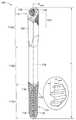
도 1a는 본 개시의 일부 구현들에 따른 광대뼈의 치과용 임플란트의 사시도이다;
도 1b는 도 1a의 광대뼈의 치과용 임플란트의 다른 사시도이다;
도 2는 환자의 입 안테 이식된 도 1a의 광대뼈의 치과용 임플란트를 도시한다;
도 3a는 도 1a의 광대뼈의 치과용 임플란트의 부분 후면도이다;
도 3b는 도 1a의 광대뼈의 치과용 임플란트의 부분 정면도이다;
도 4a는 도 1a의 광대뼈의 치과용 임플란트의 부분 측면도이다;
도 4b는 도 4a의 광대뼈의 치과용 임플란트의 단면도이다;
도 5a는 도 4a의 광대뼈의 치과용 임플란트의 부분 반대 측면도이다;
도 5b는 도 5a의 광대뼈의 치과용 임플란트의 단면도이다;
도 6a는 본 개시의 다른 일부 구현들에 따른 광대뼈의 치과용 임플란트의 부분 후면도이다;
도 6b는 도 6a의 광대뼈의 치과용 임플란트의 부분 측면도이다;
도 6c는 도 6a의 광대뼈의 치과용 임플란트의 부분 정면도이다;
도 6d는 도 6b의 광대뼈의 치과용 임플란트의 부분 반대 측면도이다;
도 7a는 본 개시의 일부 구현에 따른 광대뼈의 치과용 임플란트의 사시도이다;
도 7b는 도 7a의 광대뼈의 치과용 임플란트의 다른 사시도이다;
도 7c는 도 7a의 광대뼈의 치과용 임플란트의 측면 단면도다;
도 8a는 본 개시의 일부 구현들에 따른 광대뼈의 치과용 임플란트의 사시도이다;
도 8b는 도 8a의 광대뼈의 치과용 임플란트의 다른 사시도이다;
도 8c는 도 8a의 광대뼈의 치과용 임플란트의 측면 단면도다;
도 9a는 도 7a의 광대뼈의 치과용 임플란트의 상부 부분의 측면 입면도를 도시한다;
도 9b는 도 9a의 광대뼈의 치과용 임플란트의 상부 부분의 측면 단면도를 도시한다;
도 9c는 도 8a의 광대뼈의 치과용 임플란트의 상부 부분의 측면 입면도를 도시한다;
도 9d는 도 9c의 광대뼈의 치과용 임플란트의 상부 부분의 측면 단면도를 도시한다;
도 9e는 본 개시의 일부 구현들에 따른 광대뼈의 치과용 임플란트의 플랫폼 아래에서 교차하는 메인 중심 축과 스레디드 보어 중심 축을 갖는 광대뼈의 치과용 임플란트의 상부 부분의 측면 입면도를 도시한다;
도 9f는 도 9e의 광대뼈의 치과용 임플란트의 상부 부분의 측면 단면도를 도시한다;
도 10a는 본 개시의 일부 구현들에 따라 제1 픽스처와 결합되는 도 7a의 광대뼈의 치과용 임플란트의 상부 부분의 측면 단면도를 도시한다;
도 10b는 제1 픽스처와 결합되는 도 10a의 광대뼈의 치과용 임플란트의 상부 부분의 사시도를 도시한다;
도 10c는 본 개시의 일부 구현들에 따라 제2 픽스처와 결합되는 도 8a의 광대뼈의 치과용 임플란트의 상부 부분의 측면 단면도를 도시한다;
도 10d는 제2 픽스처와 결합되는 도 10c의 광대뼈의 치과용 임플란트의 상부 부분의 사시도를 도시한다;
도 10e는 본 개시의 일부 구현들에 따라 제3 픽스처와 결합되는 도 9e의 광대뼈의 치과용 임플란트의 상부 부분의 측면 단면도를 도시한다;
도 10f는 제3 픽스처와 결합되는 도 10e의 광대뼈의 치과용 임플란트의 상부 부분의 사시도를 도시한다.
본 개시는 다양한 수정들과 대안적인 형태들이 가능하지만, 특정 실시예들이 도면에서 예로서 도시되었으며 여기에 상세히 설명될 것이다. 그러나, 본 개시는 개시된 특정 형태들로 제한되도록 의도되지 않음을 이해해야 한다. 오히려, 본 개시는 첨부된 청구범위에 의해 정의되는 바와 같은 본 개시의 사상 및 범위 내에 속하는 모든 수정들, 등가물들 및 대안들을 포함한다.The foregoing and other advantages of the present disclosure will become apparent upon reading the detailed description below and with reference to the drawings.
1A is a perspective view of a dental implant of a cheekbone in accordance with some implementations of the present disclosure;
1B is another perspective view of the dental implant of the cheekbone of FIG. 1A ;
Fig. 2 shows the dental implant of the cheekbone of Fig. 1a implanted into the mouth of a patient;
3A is a partial rear view of the dental implant of the cheekbone of FIG. 1A ;
3B is a partial front view of the dental implant of the cheekbone of FIG. 1A ;
FIG. 4A is a partial side view of the dental implant of the cheekbone of FIG. 1A ;
Fig. 4b is a cross-sectional view of the dental implant of the cheekbone of Fig. 4a;
Fig. 5a is a partial opposite side view of the dental implant of the cheekbone of Fig. 4a;
Fig. 5b is a cross-sectional view of the dental implant of the cheekbone of Fig. 5a;
6A is a partial rear view of a dental implant of the cheekbone in accordance with some other implementations of the present disclosure;
FIG. 6B is a partial side view of the dental implant of the cheekbone of FIG. 6A ;
Fig. 6c is a partial front view of the dental implant of the cheekbone of Fig. 6a;
FIG. 6D is a partial reverse side view of the dental implant of the cheekbone of FIG. 6B ;
7A is a perspective view of a dental implant of a cheekbone in accordance with some implementations of the present disclosure;
FIG. 7B is another perspective view of the dental implant of the cheekbone of FIG. 7A ;
FIG. 7C is a side cross-sectional view of the dental implant of the cheekbone of FIG. 7A ;
8A is a perspective view of a dental implant of a cheekbone in accordance with some implementations of the present disclosure;
Fig. 8B is another perspective view of the dental implant of the cheekbone of Fig. 8A;
Fig. 8c is a side cross-sectional view of the dental implant of the cheekbone of Fig. 8a;
Fig. 9a shows a side elevational view of an upper part of the dental implant of the cheekbone of Fig. 7a;
FIG. 9B shows a side cross-sectional view of an upper part of the dental implant of the cheekbone of FIG. 9A ;
Fig. 9c shows a side elevational view of an upper part of the dental implant of the cheekbone of Fig. 8a;
FIG. 9D shows a side cross-sectional view of an upper portion of the dental implant of the cheekbone of FIG. 9C ;
9E shows a side elevation view of an upper portion of a dental implant of the cheekbone having a threaded bore central axis and a main central axis intersecting under the platform of the dental implant of the cheekbone in accordance with some implementations of the present disclosure;
Fig. 9f shows a side cross-sectional view of an upper portion of the dental implant of the cheekbone of Fig. 9e;
FIG. 10A shows a side cross-sectional view of an upper portion of the dental implant of the cheekbone of FIG. 7A engaged with a first fixture in accordance with some implementations of the present disclosure;
FIG. 10B shows a perspective view of an upper portion of the dental implant of the cheekbone of FIG. 10A engaged with a first fixture;
FIG. 10C shows a side cross-sectional view of an upper portion of the dental implant of the cheekbone of FIG. 8A engaged with a second fixture in accordance with some implementations of the present disclosure;
FIG. 10D shows a perspective view of an upper portion of the dental implant of the cheekbone of FIG. 10C engaged with a second fixture;
10E shows a side cross-sectional view of an upper portion of the dental implant of the cheekbone of FIG. 9E engaged with a third fixture in accordance with some implementations of the present disclosure;
FIG. 10f shows a perspective view of an upper portion of the dental implant of the cheekbone of FIG. 10e engaged with a third fixture;
While this disclosure is susceptible to various modifications and alternative forms, specific embodiments have been shown by way of example in the drawings and will be described in detail herein. It should be understood, however, that this disclosure is not intended to be limited to the specific forms disclosed. Rather, this disclosure includes all modifications, equivalents and alternatives falling within the spirit and scope of the disclosure as defined by the appended claims.
대략적으로 도 1a, 도 1b 및 도 2를 참조하면, 광대뼈의(zygomatic) 치과용 임플란트(100)는 대략적으로 원통형의 본체(110), 내부 보어(130), 비-회전 특징부(150) 및 비대칭 외부 특징부(120)를 포함한다. 대략적으로 원통형의 본체(110)는 대략적으로 근위(proximal) 또는 치관측(coronal) 부분(112a), 중간 부분(112b), 및 원위(distal) 또는 치근측(apical) 부분(112c)으로 나뉜다. 치근측 부분(112c)은 환자의 광대뼈에 광대뼈의 치과용 임플란트(100)를 고정시키기 위한 것이다. 광대뼈의 치과용 임플란트(100)는, 광대뼈의 치과용 임플란트(100)가 비-광대뼈의(non-zygomatic) 치과용 임플란트들 보다 상당히 길고, 이에 따라, 광대뼈의 치과용 임플란트(100)가 환자의 입(10) 안의 광대뼈(25)에 가까운 및/또는 광대뼈(25) 내부의 위턱뼈 내로 설치될 수 있다는 점에서, 다른 치과용 임플란트들과 대략적으로 다르다(도 2). 광대뼈의 치과용 임플란트들은, 비-광대뼈의 또는 보다 전통적인 치과 임플란트를 설치하기 위해 필요한 소켓을 제공하지 않는 재흡수된(resorbed) 및/또는 악화된(deteriorated) 턱뼈들을 갖는 환자들(예컨대, 암 환자들)을 위해, 필요할 수 있다. 일부 구현들에서, 하나 이상의 광대뼈의 치과용 임플란트들이 환자(하나 이상의 비-광대뼈의 치과용 임플란트들을 갖거나 갖지 않음)의 입 안에 설치되고, 하나 이상의 지대치들(abutments), 브리지들(bridges), 바들(bars), 보철 치아들(prosthetic teeth), 부착 부재들(attachment members) 또는 이들의 어떤 조합(예컨대, 보철 치아들을 포함하는 브리지)에 결합된다.1A , 1B and 2 , a zygomatic
도 1a 및 도 1b에 가장 잘 도시된 바와 같이, 광대뼈의 치과용 임플란트(100)는 대략적으로 원통형의 본체(110)의 치관측 부분(112a)과 치근측 부분(112c) 사이에 위치되는, 대략적으로 원통형의 본체(110)의 논-스레디드(non-threaded) 중간 부분(112b)을 포함한다. 치관측 부분(112a)은 그 외부 표면 둘레의 비대칭 외부 특징부(120)를 포함한다. 치근측 부분(112c)은 그 외부 표면 둘레의 외부 스레드들(113)을 포함한다. 대략적으로 원통형의 본체(110)의 치근측 부분(112c)은 치근측 외부 스레드(113)를 가로지르는(cross)(예컨대, 끊음(break up)), 광대뼈의 치과용 임플란트(100)의 원주(circumference) 둘레의 2 열의 이격된 복수의 대략적으로 수직인 플루트들(flutes)(118)을 포함한다. 플루트들(118)은, (i) 환자의 뼈 소켓으로 광대뼈의 치과용 임플란트(100)를 셀프-태핑(self-tapping) 및/또는 (ii) 설치 동안 광대뼈의 치과용 임플란트(100)를 수용하는 캐비티(예컨대, 뼈 소켓)로부터 배출될 재료의 경로를 제공하는 것에 의해, 광대뼈의 치과용 임플란트(100)의 설치를 돕는다. 더 많거나 더 적은 플루트들(118)이 고려되기도 한다.As best shown in FIGS. 1A and 1B , the
내부 보어(130)는 광대뼈의 치과용 임플란트(100)의 치관측 부분(112a) 내에 형성된다. 내부 보어(130)는, 광대뼈의 치과용 임플란트(100) 상에 지대치(도시되지 않음)를 유지시키기 위해 나사(도시되지 않음)와 나사 결합하도록, 그 내에 암(female) 또는 내부 스레드(132(도 4b)를 포함한다. 비-회전 특징부(150)는 대략적으로 치관측 부분(112a)으로부터 돌출되고, 내부 보어(130)(예컨대, 적어도 내부 보어(130)의 스레디드 부분)의 외부에 있다. 도시된 바와 같이, 비-회전 특징부(150)는 비-회전 방식으로 지대치의 대응하는 비-회전 특징부와 비-회전 결합할 수 있는 6-면의 육각형 보스(six-sided hexagonal boss)이다. 예를 들어, 4-면의 정사각형이나 직사각형 보스(도시되지 않음), 5-면의 다각형 보스(도시되지 않음), 12-면의 다각형/별 보스(도시되지 않음), 3-피스(piece)의 클로버 모양의 보스(도시되지 않음) 등과 같은 다양한 대안적인 비-회전 특징부들이 고려된다. 일부 구현들에서, 광대뼈의 치과용 임플란트는 비-회전 특징부(150)와 같은 외부 보스가 아닌 비-회전 특징부로서 내부 소켓을 갖는 내부-연결 광대뼈의 치과용 임플란트이다.The
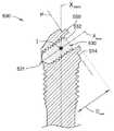
광대뼈의 치과용 임플란트(100)의 대략적으로 원통형의 본체(110)는 메인-중심 축(Xmain)을 갖는다. 메인-중심 축(Xmain)은 광대뼈의 치과용 임플란트(100)의 대략적으로 원통형의 본체(110)의 적어도 치근측 부분(112c)의 기하학적 중심(geometric center) 및/또는 대칭축(axis of symmetry)을 통과하는 직선 축/선으로 정의된다. 그러나, 광대뼈의 치과용 임플란트(100)의 메인-중심 축(Xmain)은 대략적으로 원통형의 본체(100)의 치관측 부분(112a)의 대칭축을 통과하지 않는다(예컨대, 치관측 부분(112a)의 대칭축과 일치하지 않음). 이는, 광대뼈의 치과용 임플란트(100)의 대략적으로 원통형의 본체(110)의 치관측 부분(112a)이 (1) 광대뼈의 치과용 임플란트(100)의 메인-중심 축(Xmain)에 대해, 그리고 (2) 광대뼈의 치과용 임플란트(100)의 대략적으로 원통형의 본체(110)의 나머지에 대해 각지고/각지거나 오프셋된 각진(angled) 부분(114)을 포함하기 때문이다.The generally
내부 보어(130)는 보어-중심 축(Xbore)을 갖는다. 보어-중심 축(Xbore)은 광대뼈의 치과용 임플란트(100)의 적어도 내부 보어(130)의 기하학적 중심 및/또는 대칭축을 통과하는 직선 축/선으로 정의된다. 도 4b에 가장 잘 도시된 바와 같이, 내부 보어(130)의 보어-중심 축(Xbore)은 광대뼈의 치과용 임플란트(100)의 메인-중심 축(Xmain)에 대해 상대적인 각도(θ)에 있다. 예를 들어, 각도(θ)는 약 7 도와 약 65 도 사이 또는 약 40 도와 약 65 도 사이와 같은 어떤 각도일 수 있다. 도 4b에 도시된 바와 같이, 각도(θ)는 약 55 도이다.The
내부 보어(130)는 대략적으로 원통형의 본체(100)의 외부 표면(119)과 내부 보어(130)의 내부 표면(139)에 의해 정의되는 원주 방향으로 연장되는 벽(135)을 형성한다. 원주 방향으로 연장되는 벽(135)은 도 4b에 가장 잘 도시된 바와 같이 최소 두께(tw,min) 및 최대 두께를 갖는다. 원주 방향으로 연장되는 벽(135)의 최소 및 최대 두께들은 광대뼈의 치과용 임플란트(100)의 사이즈, 내부 보어(130)의 내경(inner diameter)(임플란트에 지대치를 유지시키기 위해 사용되는 나사의 유형/사이즈에 따라 달라질 수 있음), 비대칭 외부 특징부(120)의 사이즈(예컨대, 피치(pitch)), 내부 스레드(132)의 사이즈(예컨대, 피치), 및/또는 메인-중심 축(Xmain)에 대해 상대적인 보어-중심 축(Xbore)의 각도(θ)에 따라 달라진다.The
또한, 원주 방향으로 연장되는 벽(135)의 최소 두께(tw,min) 및 최대 두께는 그 두께들이 측정되는 위치(예컨대, 광대뼈의 치과용 임플란트의 높이에 따른 수직 위치)에 의존할 수 있다는 점에 유의한다. 예를 들어, 내부 보어의 치관측 단부 근처 또는 치관측 단부에서의 원주 방향으로 연장되는 벽(135)의 최소 두께(tw,min)는 내부 보어의 원위 단부 근처 또는 원위 단부에서의 원주 방향으로 연장되는 벽의 최소 두께(tw,min)와 다를 것이다. 추가적으로, 원주 방향으로 연장되는 벽(135)의 두께는, 내부 보어가 메인-중심 축(Xmain)에 대해 상대적인 각도(θ)에 있기 때문에, 광대뼈의 치과용 임플란트의 원주(예컨대, 메인-중심 축(Xmain) 둘레의 회전 위치)에 대해 변한다. 일 예로, 광대뼈의 치과용 임플란트(100)는 약 55도의 각도(θ)를 갖는 내부 보어(130)를 갖는 3.4 직경의 광대뼈의 치과용 임플란트(공칭(nominal) 사이즈)이다. 그 예에서, 내부 보어(130)의 원위 단부 또는 원위 단부 근처에서의 원주 방향으로 연장되는 벽(135)의 최소 두께(tw,min)는 약 0.08 mm이며, 이는 광대뼈의 치과용 임플란트(100)의 대략적으로 원통형의 본체(100)의 제1 측면(110a)에 인접한다.It is also noted that the minimum thickness (tw,min ) and the maximum thickness of the
상기 설명에 의해 이해될 수 있고 도 4b에 가장 잘 도시된 바와 같이, 원주 방향으로 연장되는 벽(135)의 두께는, 내부 보어(130)가 메인-중심 축(Xmain)에 대해 상대적인 각도(θ)에 있기 때문에, 광대뼈의 치과용 임플란트(100)의 원주(예컨대, 메인-중심 축(Xmain) 둘레의 회전 위치)에 대해 변한다. 내부 보어(130)의 원위 단부 또는 원위 단부 근처에서의 대략적으로 원통형의 본체(110)의 수평 단면에 대해, 원주 방향으로 연장되는 벽(135)의 두께는, (1) 제1 측면(110a)에 인접한 내부 보어(130)의 원위 단부 또는 원위 단부 근처에서의 최소 두께(tw,min)에서, (2) 제2 반대 측면(110b)에 인접한 내부 보어(130)의 원위 단부 또는 원위 단부 근처에서의 상대적으로 더 큰 및/또는 최대 두께까지, 광대뼈의 치과용 임플란트(100)의 원주에 대해 변한다. 광대뼈의 치과용 임플란트(100)에 대해 도 4b에 도시된 예시적인 구현에 기초하여, (i) 대략적으로 원통형의 본체(110)의 최대 외경(outer diameter)(Dmax,c)(예컨대, 4 mm의 공칭 외경) 대(to) (ii) 대략적으로 원통형의 본체(110)의 제1 측면(110a)에 인접한 원주 방향으로 연장되는 벽(135)의 가장 얇은 부분(예컨대, 두께(tw.min))의 비(ratio)는 4 mm/0.08 mm이며, 이는 50과 같다.As can be understood by the above description and best shown in FIG. 4B , the thickness of the
요약하면, 원주 방향으로 연장되는 벽(135)은 원주 방향으로 연장되는 벽(135)의 나머지에 비해 상대적으로 얇은 두께를 갖는 하나 이상의 부분들 또는 섹션들을 갖는다. 원주 방향으로 연장되는 벽(135)의 이러한 부분들은, 광대뼈의 치과용 임플란트(100)가 장착될 때(예컨대, 지대치 및 크라운과 결합되고, 환자의 입 안에서의 저작 목적들을 위해 사용됨), 파손/파괴/스냅되기 더 쉽다. 본 개시의 광대뼈의 치과용 임플란트들은 이전의 치과용 임플란트들에 비해 상대적으로 더 작은 외경들 및/또는 상대적으로 더 큰 각도들로 가공될 수 있고, 그러한 상대적으로 더 작은 광대뼈의 치과용 임플란트들은, 적어도 비대칭 외부 특징부(120)의 논-그루브드 영역(non-grooved area)(125)(아래에 설명됨)이 도 3a에 가장 잘 도시된 바와 같이 원주 방향으로 연장되는 벽(135)의 가장 얇은 부분에 인접하여 위치되기 때문에, 그러한 더 작은 사이즈의 광대뼈의 치과용 임플란트들을 필요로 하는 환자의 입 영역들 내에 사용될 수 있다.In summary, the
이제 도 3a 내지 도 5b를 참조하면, 광대뼈의 치과용 임플란트(100)의 대략적으로 원통형의 본체(110)의 치관측 부분(112a)은 비대칭 외부 특징부(120)를 포함하고, 여기서 비대칭 외부 특징부(120)는 환자의 입 안에 설치될 때, 치조골과 직접 맞물리도록 구성된다. 비대칭 외부 특징부(120)는 복수의 원주 방향으로 연장되는 그루브들(121)을 포함한다. 복수의 원주 방향으로 연장되는 그루브들(121)은 연속적이거나, 간헐적이거나, 분할되거나, 서로 평행하거나, 수평의, 스레디드, 절삭된(truncated) 스레드들에 대해 각지거나, 또는 이들의 어떤 조합일 수 있다.Referring now to FIGS. 3A-5B , the
원주 방향으로 연장되는 그루브들(121)의 각각은 그 단부들 사이에서 연장되는 원주 길이(circumferential length)를 갖는다. 예를 들어, 도 3a에 도시된 바와 같이, 제1 원주 방향으로 연장되는 그루브(123a)는, 제1 원주 방향으로 연장되는 그루브(123a)의 제1 단부(122a)와 제2 단부(122b) 사이의 거리로 정의되는 원주 길이(Lg)를 갖는다. 일부 구현들에서, 복수의 원주 방향으로 연장되는 그루브들(121)의 각각의 원주 길이(Lg)는 동일하거나, 상이하거나, 또는 이들의 조합이다. 예를 들어, 도 3a 및 도 4a에 가장 잘 도시된 바와 같이, 복수의 원주 방향으로 연장되는 그루브들 중 제1 부분(121a)의 원주 길이(Lg)는 치근측으로(apically) 감소한다. 복수의 원주 방향으로 연장되는 그루브들 중 제2 부분(121b)의 원주 길이(Lg)는 치근측으로 증가한다. 다시 말해, 복수의 원주 방향으로 연장되는 그루브들 중 제1 부분(121a)의 단부들은 치근측 방향에서 내측으로 테이퍼지고(taper), 복수의 원주 방향으로 연장되는 그루브들 중 제2 부분(121b)의 단부들은 치근측 방향에서 외측으로 테이퍼진다.Each of the
원주 방향으로 연장되는 그루브들(121) 중 하나 이상은 논-그루브드 영역(125)을 공동으로(collectively) 형성하는 갭(gap)을 포함할 수 있다. 도 3a에 가장 잘 도시된 바와 같이, 제2 원주 방향으로 연장되는 그루브(123b)는 갭(124)을 갖는다. 도시된 바와 같이, 복수의 원주 방향으로 연장되는 그루브들 중 제3 부분(121c)은 논-그루브드 영역(125)을 형성하는 갭들을 포함하는 세 개의 그루브들을 포함한다. 제3 부분(121c) 내의 더 많거나 더 적은 그루브들이 고려된다. 상술된 바와 같이, 논-그루브드 영역(125)은 대략적으로 원통형의 본체의 제1 측면(110a) 상의 원주 방향으로 연장되는 벽(135)의 가장 얇은 부분에 인접한다. 이와 같이, 내부 보어(130)의 원위 단부 근처 또는 원위 단부에서의 원주 방향으로 연장되는 벽(135)의 최소 두께(tw.min)는, 원주 방향으로 연장되는 벽(135)의 두께를 감소시킬 수 있고, 이에 따라, 광대뼈의 치과용 임플란트(100)가 장착될 때 파괴될 가능성이 너무 높은 그루브드 또는 스레디드 영역을 그 안에 가짐으로써 더 감소되지 않는다. 요약하면, 도 4a에 가장 잘 도시된 바와 같이, 복수의 원주 방향으로 연장되는 그루브들 중 제1 부분(121a)은 광대뼈의 치과용 임플란트(100)의 치관측 단부로부터 가장 멀리 형성되고; 복수의 원주 방향으로 연장되는 그루브들 중 제3 부분(121c)은 광대뼈의 치과용 임플란트(100)의 치광측 단부에 가장 가깝게 형성되고; 복수의 원주 방향으로 연장되는 그루브들 중 제2 부분(121b)은 제1 부분(121a)과 제3 부분(121c) 사이에 형성된다.One or more of the
일부 구현들에서, 복수의 원주 방향으로 연장되는 그루브들(121)의 각각은 스레드의 적어도 일부를 형성한다(예컨대, 복수의 절삭된 스레드들을 형성함). 대안적인 일부 구현들에서, 복수의 원주 방향으로 연장되는 그루브들(121)에 의해 형성되는 스레드(절삭된 스레드들)와 치근측 외부 스레드(113)는 동일하다(예컨대, 동일한 피치, 동일한 단면 및/또는 동일한 개수의 스타트들(starts) 등). 다른 구현들에서, 복수의 원주 방향으로 연장되는 그루브들(121)과 치근측 외부 스레드들(113)은 상이하다. 동일하거나 상이한 피치들을 갖는 복수의 원주 방향으로 연장되는 그루브들(121)에 의해 형성되는 스레드와 치근측 외부 스레드(113) 둘 다 상의 다중-리드(multi-lead) 스레드들과 같은, 다양한 대안적인 스레드들, 피치들 및 비율들이 고려된다. 복수의 원주 방향으로 연장되는 그루브들(121)에 의해 형성되는 스레드와 치근측 외부 스레드(113)는 함께 혼합되거나(예컨대, 중간 부분(112b) 근처에서), 도 1a 및 도 1b에서 가장 잘 도시된 바와 같이 분리되어 구별될 수 있다(예컨대, 접촉하지 않음).In some implementations, each of the plurality of circumferentially extending
일부 구현들에서, 복수의 원주 방향으로 연장되는 그루브들(121)에 의해 형성되는 스레드(치관측 부분(112a) 둘레)는 마이크로 스레드이고, 외부 스레드(113)(치근측 부분(112c) 둘레)는 메인 스레드(113)이며, 여기서 메인 스레드(113)는 뼈와 더 깊게 일차적으로 맞물리기 위한 것이다. 그러한 구현들에서, 메인 스레드(113)의 스레드 깊이(Dt,main) (도 1a)에 비해, 마이크로 스레드는 상대적으로 작은 스레드 깊이(Dt,micro)를 갖는다(도 4a). 이와 같이, 광대뼈의 치과용 임플란트(100)의 치관측 단부에서의 원주 방향으로 연장되는 벽(135)은, 비대칭 외부 특징부(120)의 스레드 깊이(Dt,micro)가 치근측 외부 스레드(113)의 스레드 깊이(Dt,main)만큼 큰 경우 보다, 상대적으로 더 두꺼울 수 있다. 원주 방향으로 연장되는 벽(135)이 상대적으로 더 두꺼우면, 광대뼈의 치과용 임플란트(100)는 상대적으로 더 강하다. 또한, 광대뼈의 치과용 임플란트(100)의 치관측 부분(112a)에서의 마이크로 스레드(또는 그루브)를 갖는 것은, 환자의 뼈에 하중을 전달하는 능력을 증가시키고, 골유착 프로세스를 돕기도 한다.In some implementations, the thread formed by the plurality of circumferentially extending grooves 121 (around the
일부 예시적인 구현들에서, 복수의 원주 방향으로 연장되는 그루브들(121)에 의해 형성되는 스레드의 스레드 깊이(Dt,micro)는 약 0.05 mm 내지 0.4 mm의 범위 내에 있고, 치근측 외부 스레드의 스레드 깊이(Dt,main)는 약 0.2 mm 내지 약 0.6 mm의 범위 내에 있다. 다른 일부 예시적인 구현들에서, 복수의 원주 방향으로 연장되는 그루브들(121)에 의해 형성되는 스레드의 스레드 깊이(Dt,micro)는 약 0.1 mm 내지 0.2 mm의 범위 내에 있고, 치근측 외부 스레드의 스레드 깊이(Dt,main)는 약 0.3 mm 내지 약 0.5 mm의 범위 내에 있다. 예를 들어, 복수의 원주 방향으로 연장되는 그루브들(121)의 스레드 깊이(Dt,micro)는 약 0.15 mm이고, 치근측 외부 스레드의 스레드 깊이(Dt,main)는 약 0.45 mm이다.In some example implementations, the thread depth (Dt,micro ) of the thread formed by the plurality of circumferentially extending
도 2에 가장 잘 도시된 바와 같이, 설치될 때, 광대뼈의 치과용 임플란트(100)의 대략적으로 원통형의 본체(110)의 제1 측면(110a)은 환자의 치조골(15)과 맞물리도록 위치된다. 또한, 광대뼈의 치과용 임플란트(100)는 뼈 성장을 촉진하는 거칠기(roughness)를 제공하기 위해 제1 측면(110a) 상의 비대칭 외부 특징부(120)를 포함하고 위치시킨다. 광대뼈의 치과용 임플란트(100)의 제2 반대 측면(110b)은 일반적으로 연조직과 직접 접촉하고, 제2 반대 측면(110b) 상에 복수의 원주 방향으로 연장되는 그루브들(121)을 포함하는 것은 미학적으로 바람직하지 않은 연조직 팽창(bulge)을 생성하고/생성하거나 연조직을 자극할 수 있기 때문에, 복수의 원주 방향으로 연장되는 그루브들(121)은 대략적으로 원통형의 본체(110)(비대칭 외부 특징부(120)의 비대칭 형상을 도움) 둘레에서 모두 연장되지 않는다.As best shown in FIG. 2 , when installed, the
일부 구현들에 따르면, 광대뼈의 치과용 임플란트(100)는 환자의 해부학적 구조(예컨대, 환자가 연조직이 광대뼈의 치과용 임플란트(100)의 치관측 단부(112a)와 직접 접촉하는 입 안에 얼마나 많은 뼈와 연조직을 가지고 있는 지)에 따라 대략적으로 원통형의 본체(110)를 변형하기 위해 외과의 및/또는 임상의가 커스터마이즈할 수 있다. 일부 구현들에서, 광대뼈의 치과용 임플란트(100)의 대략적으로 원통형의 본체(110)는 제2 반대 측면(110b) 상에 대략적으로 평평한 특징부(160)를 포함하고, 이에 따라, 대략적으로 평평한 특징부(160)가 환자의 연조직(20)과 맞물리도록 구성되어, 대략적으로 평평한 특징부(160)(예컨대, 대략적으로 원통형의 표면) 없이 발생하는 것 보다 적은 팽창(bulging)을 생성하고, 이는 연조직이 결과적으로 얇아지는 것(예컨대, 보다 미학적으로 만족스러운 모습)을 도울 수 있다. 일부 예시들에서, 평평한 특징부(160)는 대략적으로 원통형의 본체(110)의 치관측 부분(112a) 상에 형성되고; 다른 예시들에서, 평평한 특징부(160)는 대략적으로 원통형의 본체(110)의 치관측 부분(112)으로부터 컷아웃(cutout)된다.According to some implementations, the
일부 예시적인 구현들에서, 비대칭 외부 특징부(120)는 4 mm와 20 mm 사이의, 메인-중심 축에 따른 전체 길이를 갖는다. 일부 구현들에서, 치근측으로 감소하는 원주 길이들을 갖는 그루브들(121)을 포함하는 복수의 원주 방향으로 연장되는 그루브들 중 제1 부분(121a)은 2 mm와 10 mm 사이의, 메인-중심 축에 따른 전체 길이를 갖는다. 치근측으로 증가하는 원주 길이들을 갖는 그루브들(121)을 포함하는 복수의 원주 방향으로 연장되는 그루브들 중 제2 부분(121b)은 2 mm와 4 mm 사이의, 메인-중심 축에 따른 전체 길이를 갖는다. 갭들(124)을 포함하는 복수의 원주 방향으로 연장되는 그루브들 중 제3 부분(121c)은 2 mm와 4 mm 사이의, 메인-중심 축에 따른 전체 길이를 갖는다.In some example implementations, the asymmetric
그러한 일부 구현들에서, 비대칭 외부 특징부(120)의 길이에 대한 대략적으로 원통형의 본체(110)의 길이(L)(도 1a)의 비는 약 2 내지 약 18 사이이다. 그러한 일부 구현들에서, 복수의 원주 방향으로 연장되는 그루브들 중 제1 부분(121a)의 길이에 대한 대략적으로 원통형의 본체(110)의 길이(L)(도 1a)의 비는 약 2 내지 약 35 사이이다. 그러한 일부 구현들에서, 복수의 원주 방향으로 연장되는 그루브들 중 제2 부분(121b)의 길이에 대한 대략적으로 원통형의 본체(110)의 길이(L)(도 1a)의 비는 약 5 내지 약 35 사이이다. 그러한 일부 구현들에서, 복수의 원주 방향으로 연장되는 그루브들 중 제3 부분(121c)의 길이에 대한 대략적으로 원통형의 본체(110)의 길이(L)(도 1a)의 비는 약 5 내지 약 35 사이이다.In some such implementations, the ratio of the length L of the generally cylindrical body 110 ( FIG. 1A ) to the length of the asymmetric
본 개시의 전체에 걸쳐, 다양한 사이즈의 치과용 임플란트들이 참조된다. 본 개시의 다양한 치과용 임플란트들을 확인하기 위해, 광대뼈의 치과용 임플란트들이 공칭 사이즈를 갖는 것으로 참조될 수 있다. 예를 들어, 공칭 사이즈는 일반적으로 또는 명목상 광대뼈의 치과용 임플란트의 최대 외경 또는 너비(width)를 나타낼 수 있다. 이 최대 외경은 치관측 부분(112a)의 최대 외경(Dmax,c)을 나타낼 수 있다(도 3b). 예를 들어, 광대뼈의 치과용 임플란트(100)는, 치관측 부분(112a)의 공칭 최대 외경(Dmax,c)인 3.4 mm의 치과용 임플란트로 지칭될 수 있다. 명목상, 외경(Dmax,c)은 약 3.4 mm이고, 반드시 정확한 3.4 mm는 아니다. 약 3.4 mm는, 치수가 약 ± 0.1 mm의 공차를 갖는다는 것을 의미한다. 다른 예로서, 광대뼈의 치과용 임플란트(100)는, 치관측 부분(112a)의 공칭 최대 외경(Dmax,c)인 5.0 mm의 치과용 임플란트로 지칭될 수 있다. 명목상, 외경(Dmax,c)은 약 5.0 mm이고, 반드시 정확한 5.0 mm는 아니다. 약 5.0 mm는, 치수가 약 ± 0.1 mm의 공차를 갖는다는 것을 의미한다. 예를 들어, 3.0, 3.5, 4.0, 4.5, 5.0, 5.5, 6.0 등과 같은 다양한 다른 공칭 최대 외경의 치과용 임플란트들이 고려된다.Throughout this disclosure, reference is made to dental implants of various sizes. To identify the various dental implants of the present disclosure, dental implants of the cheekbone may be referred to as having a nominal size. For example, the nominal size may generally or nominally represent the maximum outer diameter or width of a dental implant in the cheekbone. This maximum outer diameter may represent the maximum outer diameter Dmax,c of the
일부 구현들에서, 대략적으로 원통형의 본체(110)의 치관측 부분(112a)은 대략적으로 원통형의 본체(110)의 논-스레디드 중간 부분(112b)의 최대 외경 및 대략적으로 원통형의 본체(110)의 치근측 부분(112c)의 최대 외경 보다 상대적으로 더 큰 최대 외경을 갖는다. 예를 들어, (i) 스레디드 치관측 부분(112a)의 최대 외경은 약 4.1 mm이고, (ii) 스레디드 치근측 부분(112c)의 최대 외경 및 논-스레디드 중간 부분(112b)의 최대 외경은 약 3.2 mm와 약 4 mm 사이이다. 대안적으로, 스레디드 치근측 부분(112c)의 최대 외경 및 논-스레디드 중간 부분(112b)의 최대 외경은 스레디드 치관측 부분(112a)의 최대 외경과 동일하거나 거의 동일하다.In some implementations, the
이제, 환자의 입 안에, 광대뼈의 치과용 임플란트(100), 광대뼈의 치과용 임플란트(300)(아래에 설명됨), 또는 광대뼈의 치과용 임플란트(400)(아래에 설명됨), 또는 어떤 광대뼈의 치과용 임플란트를 설치하는 방법이, 본 개시의 일부 구현들에 따라 설명된다. 먼저, 외과의 또는 임상의는 환자의 해부학적 구조(예컨대, 입, 뼈, 연조직, x-레이들, CT 스캔 등)를 평가하고, 평가에 대해 적어도 부분 적으로 기초하여 (예컨대, 광대뼈의 치과용 임플란트들의 세트(set)로부터) 광대뼈의 치과용 임플란트(100, 300, 400)를 선택한다. 선택된 광대뼈의 치과용 임플란트(100, 300, 400)는 환자에 대해 적절한 직경과 길이를 갖는다. 일부 구현들에서, 환자의 입 안에 설치될 선택된 광대뼈의 치과용 임플란트(100, 300, 400)는 30 mm와 60 mm 사이의 길이를 갖는다. 또한, 외과의 및/또는 임상의는 광대뼈의 치과용 임플란트(100, 300, 400)의 설치 부위에 인접하여, 환자의 입 안의 연조직을 평가한다. 특히, 광대뼈의 치과용 임플란트(100, 300, 400)의 경우, 외과의 및/또는 임상의는 대략적으로 평평한 특징부(160, 360)가 더 변형되어야 하는지(예컨대, 셰이브되어야(shaved) 하는지, 절단되어야 하는지, 추가되어야 하는지(added)/빌드업되어야(built up) 하는지 등, 또는 어떤 조합)를 결정하기 위해 평가하고, 이에 따라, 연조직이 설치되는 광대뼈의 치과용 임플란트(100, 300, 400)에 의해 미관적으로 만족스러운 외관을 갖는다. 이 후, 이 연조직 평가에 대해 적어도 부분적으로 기초하여, 외과의 및/또는 임상의는 대략적으로 원통형의 본체(110, 310)의 제2 측면(110b, 310b)(임플란트(100)에 대한 도 4b 및 임플란트(300)에 대한 도 7c) 상의 광대뼈의 치과용 임플란트(100, 300)의 대략적으로 원통형의 본체(110, 310)를 변형하고, 이로써 환자의 입 안에 설치될 때, 미관적으로 만족스러운 치은(gingival) 외관(예컨대, 연조직의 팽창 감소, 연조직의 팽창 증가, 치은 조직의 모양/프로파일(profile)/마진(margin) 변경 등)을 생성하는 데 도움이 되는, 광대뼈의 치과용 임플란트(100, 300)의 변형된 버전을 형성한다.Now, in a patient's mouth,
비대칭 외부 특징부(120)와 대향하는(opposing) 대략적으로 평평한 특징부(160)가 대략적으로 원통형의 본체(110)의 메인-중심 축(Xmain) 둘레의 특정 배향(orientation) 및 위치를 갖는 것과 같이 도 1a 내지 도 5b에 도시되어 있지만, 대안적인 일부 구현들에서, 비대칭 외부 특징부(120) 및/또는 대향하는 대략적으로 평평한 특징부(160)는 대략적으로 원통형의 본체(110)의 메인-중심 축(Xmain)을 중심으로 회전할 수 있고, 이에 따라, 비대칭 외부 특징부(120) 및/또는 대향하는 대략적으로 평평한 특징부(160)는 광대뼈의 치과용 임플란트(100)의 내부 보어(130)와 비-회전 특징부(150)에 대해 상이한 배향 및/또는 위치를 갖는 것이 고려된다.A generally
예를 들어, 그러한 대안적인 일부 구현들에서, 비대칭 외부 특징부(120) 및/또는 대향하는 대략적으로 평평한 특징부(160)는, 시계 방향 또는 반시계 방향으로 약 5도, 시계 방향 또는 반시계 방향으로 약 10도, 시계 방향 또는 반시계 방향으로 약 15 도, 시계 방향 또는 반시계 방향으로 약 20 도, 시계 방향 또는 반시계 방향으로 약 25 도, 시계 방향 또는 반시계 방향으로 약 45 도, 시계 방향 또는 반시계 방향으로 약 60 도, 시계 방향 또는 반시계 방향으로 약 75 도, 시계 방향 또는 반시계 방향으로 약 90 도, 또는 그 사이의 어떤 양/도로, 대략적으로 원통형의 본체(110)의 메인-중심 축(Xmain)을 중심으로 도 1a 내지 도 5b에 도시된 그들의 위치들에 대해 회전된다.For example, in some such alternative implementations, the asymmetrical
그러한 대안들의 특정 예가 도 6a 내지 도 6d에 도시되어 있다. 도시된 바와 같이, 광대뼈의 치과용 임플란트(200)의 비대칭 외부 특징부(120)와 대향하는 대략적으로 평평한 특징부(160)는 광대뼈의 치과용 임플란트(100)(도1a 내지 도 5b)의 비대칭 외부 특징부(120) 및 대향하는 대략적으로 평평한 특징부(160)의 배향 및 위치에 비해, 대략적으로 원통형의 본체(110)의 메인-중심 축(Xmain)을 중심으로 약 90도 회전된다는 점을 제외하고는, 광대뼈의 치과용 임플란트(200)는 광대뼈의 치과용 임플란트(100)와 동일하거나 유사하며, 여기서, 유사한 참조번호들은 유사한 구성 요소들에 사용된다. 추가적으로, 비대칭 외부 특징부(120)의 원주 방향으로 연장되는 그루브들(121) 중 하나 이상의 원주 길이들(Lg)은 각진 치과용 임플란트인 광대뼈의 치과용 임플란트(200)로 인해, 치관측 단부에서의 각진 페이스(face)에 대해 맞도록 수정된다. 도 6a에 가장 잘 도시된 바와 같이, 원주 방향으로 연장되는 그루브들(121) 중 가장 치관측의 세 개는 바로 더 치근측의 그루브(121)에 비해 충분향 양으로 짧아지고, 이에 따라, 논-그루브드 영역(125)은 원주 방향으로 연장되는 벽(135)의 가장 얇은 부분에 인접하게 유지된다. 적어도 상술된 이유들로 논-그루브드 영역(125)을 유지하기 위해, 그루브들(121) 중 더 많거나 더 적은 수가 짧아질 수 있다.Specific examples of such alternatives are shown in FIGS. 6A-6D . As shown, the generally
상술되고 도 1a 내지 도 5b에 도시된 광대뼈의 치과용 임플란트(100)는 대략적으로 원통형의 본체(110)의 후면 또는 배면에 대략적으로 위치되는 비대칭 외부 특징부(120)를 포함하고, 대략적으로 원통형의 본체(110)의 전면에 대략적으로 위치되는 대향하는 대략적으로 평평한 특징부(160)를 포함하며, 여기서, 전면은 비-회전 특징부(150)가 향하거나 가리키는 방향에 의해 정의된다. 비대칭 외부 특징부(120)와 대략적으로 평평한 특징부(160)의 그러한 배향을 갖는 광대뼈의 치과용 임플란트(100)는 시프트되지 않는(non-shifted) 비대칭 외부 특징부를 갖는 광대뼈의 치과용 임플란트로 지칭될 수 있다.The
상술되고 도 6a 내지 도 6d에 도시된 광대뼈의 치과용 임플란트(200)는 대략적으로 원통형의 본체(110)의 측면에 대략적으로 위치되는 비대칭 외부 특징부(120)를 포함하고, 대략적으로 원통형의 본체(110)의 반대 측면에 대략적으로 위치되는 대향하는 대략적으로 평평한 특징부(160)를 포함하며, 여기서, 전면은 비-회전 특징부(150)가 향하거나 가리키는 방향에 의해 정의된다. 비대칭 외부 특징부(120)와 대략적으로 평평한 특징부(160)의 그러한 배향을 갖는 광대뼈의 치과용 임플란트(200)는 시프트되는 비대칭 외부 특징부를 갖는 광대뼈의 치과용 임플란트로 지칭될 수 있다.The
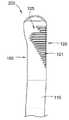
대략적으로 도 7a 내지 도 7c를 참조하면, 광대뼈의 치과용 임플란트(300)는 대략적으로 원통형의 본체(310), 내부 스레디드 보어(330), 비-회전 특징부(350) 및 비대칭 외부 특징부(320)를 포함한다. 대략적으로 원통형의 본체(310)는 제1 측면(310a) 및 제2 반대 측면(310b)을 갖는다. 또한, 대략적으로 원통형의 본체(310)는 대략적으로 근위 또는 치관측 부분(312a), 중간 부분(312b), 및 원위 또는 치근측 부분(312c)으로 나뉠 수 있다. 치근측 부분(312c)은 환자의 광대뼈에 광대뼈의 치과용 임플란트(300)를 고정시키기 위한 것이다.7A-7C , the
일부 구현들에서, 광대뼈의 치과용 임플란트(300)의 대략적으로 원통형의 본체(310)는 제2 반대 측면(310b) 상의 대략적으로 평평한 특징부(360)를 포함하고, 이에 따라, 대략적으로 평평한 특징부(360)는 환자의 연조직과 맞물리도록 구성되어(예컨대, 대략적으로 평평한 특징부(160)가 도 2의 연조직(20)과 맞물리는 방식과 유사함), 대략적으로 평평한 특징부(360)(예컨대, 대략적으로 원통형의 표면) 없이 발생하는 것 보다 적은 팽창을 생성하고, 이는 연조직이 결과적으로 얇아지는 것(예컨대, 보다 미학적으로 만족스러운 모습)을 도출 수 있다.In some implementations, the generally
광대뼈의 치과용 임플란트(300)는, 광대뼈의 치과용 임플란트(300)가 비-광대뼈의 치과용 임플란트들 보다 상당히 길고, 이에 따라, 광대뼈의 치과용 임플란트(300)가 도 2에 도시된 광대뼈의 치과용 임플란트(100)와 동일하거나 유사한 방식으로 환자의 입 안의 광대뼈에 가까운 및/또는 광대뼈 내부의 위턱뼈 내로 설치될 수 있다는 점에서, 다른 치과용 임플란트들과 대략적으로 다르다. 광대뼈의 치과용 임플란트(300)는 많은 측면들에서 광대뼈의 치과용 임플란트(100)와 동일하거나 유사하다; 그러나, 광대뼈의 치과용 임플란트(300)는 주로, (1) 광대뼈의 치과용 임플란트(300)의 대략적으로 평평한 특징부(360)가 광대뼈의 치과용 임플란트(100)의 대략적으로 평평한 특징부(160) 보다 상대적으로 더 치근측으로(예컨대, 치관측 부분(312a)에서 치근측 부분(312c)로) 연장되고; (2) 광대뼈의 치과용 임플란트(300)의 비대칭 외부 특징부(320)가 광대뼈의 치과용 임플란트(100)의 논-그루브드 영역(125)과 같은 논-그루브드 영역을 포함하지 않는다는 점에서, 광대뼈의 치과용 임플란트(100)와 다르다.The
도 7a 내지 도 7c에 도시된 바와 같이, 광대뼈의 치과용 임플란트(300)는 대략적으로 원통형의 본체(310)의 치관측 부분(312a)과 치근측 부분(312c) 사이에 위치되는, 대략적으로 원통형의 본체(310)의 논-스레디드 중간 부분(312b)을 포함한다. 대안적으로, 논-스레디드 중간 부분(312b)의 전부 또는 일부는 하나 이상의 스레드들, 그루브들, 돌출부들, 또는 이들의 어떤 조합을 포함할 수 있다.7A-7C , the
치관측 부분(312a)은 복수의 원주 방향으로 연장되는 그루브들(321)을 포함하는, 그 외부 표면 둘레의 비대칭 외부 특징부(320)를 포함한다. 비대칭 외부 특징부(320)는 상술된 광대뼈의 치과용 임플란트(100)의 논-그루브드 영역(125)과 같은 논-그루브드 영역을 포함하지 않는다는 점을 제외하고, 비대칭 외부 특징부(320) 및 복수의 원주 방향으로 연장되는 그루브들(321)은 광대뼈의 치과용 임플란트(100)의 비대칭 외부 특징부(120) 및 복수의 원주 방향으로 연장되는 그루브들(121)과 동일하거나 유사하다. 그러한 일부 구현들에 따르면, 광대뼈의 치과용 임플란트(300)는 광대뼈의 치과용 임플란트(100) 보다 상대적으로 더 큰 직경을 갖기 때문에, 광대뼈의 치과용 임플란트(300)는 논-그루브드 영역을 포함하지 않고, 이에 따라, 내부 스레디드 보어(330)의 바닥부(bottom)(331)(도 7c)는 광대뼈의 치과용 임플란트(300)의 제1 측면(310a)의 외부 표면으로부터 충분히 이격된다. 달리 말하면, 원주 방향으로 연장되는 벽(135)과 동일하거나 유사한, 내부 스레디드 보어(330)에 의해 형성되는 원주 방향으로 연장되는 벽(335)(도 7c)은, 복수의 원주 방향으로 연장되는 그루브들(321)이 쉽게 파손/스냅/파괴되지 않고, 제1 측면(310a)을 따라 그리고 내부 스레디드 보어(330)의 바닥부에 인접하여 연장되도록 허용하기에 충분한 최소 두께를 갖는다.The
일부 구현들에서, 복수의 원주 방향으로 연장되는 그루브들(321)의 각각의 원주 길이(Lg)는 동일하거나, 상이하거나, 또는 이들의 조합이다. 예를 들어, 도 7b 및 도 9a에 가장 잘 도시된 바와 같이, 복수의 원주 방향으로 연장되는 그루브들 중 제1 부분(321a)의 원주 길이(Lg)는 복수의 원주 방향으로 연장되는 그루브들 중 제1 부분(121a)과 동일하거나 유사한 방식으로, 치근측으로 감소한다. 복수의 원주 방향으로 연장되는 그루브들 중 제2 부분(321b)의 원주 길이(Lg)는 복수의 원주 방향으로 연장되는 그루브들 중 제2 부분(121b)과 동일하거나 유사한 방식으로, 치근측으로 증가한다. 다시 말해, 복수의 원주 방향으로 연장되는 그루브들 중 제1 부분(321a)의 단부들은 치근측 방향에서 내측으로 테이퍼지고, 복수의 원주 방향으로 연장되는 그루브들 중 제2 부분(321b)의 단부들은 치근측 방향에서 외측으로 테이퍼진다.In some implementations, the circumferential length Lg of each of the plurality of circumferentially extending
치근측 부분(312c)은 광대뼈의 치과용 임플란트(100)의 외부 스레드들(113)과 동일하거나 유사한, 그 외부 표면 둘레의 외부 스레드들(313)을 포함한다. 대략적으로 원통형의 본체(310)의 치근측 부분(312c)은 치근측 외부 스레드(313)를 가로지르는(예컨대, 끊음) 광대뼈의 치과용 임플란트(300)의 원주 둘레의 1 열(317)의 이격된 복수의 대략적으로 수직인 플루트들(318)을 포함한다. 플루트들(318)은, (i) 환자의 뼈 소켓으로 광대뼈의 치과용 임플란트(300)를 셀프-태핑 및/또는 (ii) 설치 동안 광대뼈의 치과용 임플란트(300)를 수용하는 캐비티(예컨대, 뼈 소켓)로부터 배출될 재료의 경로를 제공하는 것에 의해, 광대뼈의 치과용 임플란트(300)의 설치를 돕는다. 단일 열 내에서 및/또는 하나 이상의 추가적인 열들(예컨대, 광대뼈의 치과용 임플란트(100)에서 2 열들의 플루트들(118)과 관련하여 상술된 바와 같음) 내에서, 더 많거나 더 적은 플루트들(318)이 고려되기도 한다.The
내부 스레디드 보어(330)는 광대뼈의 치과용 임플란트(300)의 치관측 부분(312a) 내에 형성되고, 이는 상술된 광대뼈의 치과용 임플란트(100)의 내부 보어(130)와 동일하거나 유사하다. 내부 스레디드 보어(330)는, 광대뼈의 치과용 임플란트(300) 상에 지대치(도시되지 않음) 및/또는 제1 픽스처(601a)(도 10a 및 도 10b에 도시되고, 아래에 설명됨)를 유지시키기 위해 제1 나사(602a)(도 10a 및 도 10b에 도시됨)와 나사 결합하도록, 그 내에 암 또는 내부 스레드(332)를 포함한다. 내부 스레디드 보어(330)는 최대 깊이(DMAX)를 갖는다. 일부 구현들에서, 최대 깊이(DMAX)는 약 1.5 mm, 1.6 mm, 1.7 mm, 1.8 mm, 1.9 mm, 2.0 mm, 2.1 mm, 2.2 mm, 2.3 mm, 2.4 mm, 2.5 mm, 2.6 mm, 2.7 mm, 2.8 mm, 2.9 mm 또는 3.0 mm이다. 도시된 바와 같이 최대 깊이(DMAX)는 비-회전 특징부(350)의 깊이를 포함하는 것으로 도시된다. 대안적으로, 최대 깊이(DMAX)는 비-회전 특징부(350)의 깊이를 포함하지 않는다. 예를 들어, 최대 깊이(DMAX)는 지대치들, 픽스처들, 툴들(tools), 크라운들, 보철물들(prostheses) 등과 같이 광대뼈의 치과용 임플란트(300)와 맞물리는 표준 나사들의 콤포넌트들(components)과 함께 작동하도록 선택된다. 최대 깊이(DMAX)가 일반적으로 광대뼈의 치과용 임플란트(300)와 맞물리는 콤포넌트들과 함께 제공되는 표준 길이 나사들을 수용할만큼 충분히 크지 않으면, 제공된 나사들은 작동하지 않을 것이다(예컨대, 나사 머리가 완전히 맞물리거나 안착되지(seated) 않도록, 나사가 끝남). 이와 같이, 광대뼈의 치과용 임플란트와 맞물리는 콤포넌트들과 함께 제공되는 표준 나사들의 길이를 고려하여, 광대뼈의 치과용 임플란트의 최대 깊이(DMAX)가 선택되는 것이 바람직할 수 있다. 일부 구현들에 따르면, 광대뼈의 치과용 임플란트들과 맞물리는 콤포넌트들과 함께 제공되는 나사들은 약 3 mm와 약 4 mm 사이의 길이를 갖는다. 대안적으로, 상대적으로 더 짧은 나사들이 상대적으로 더 짧은 스레디드 보어들과 함께 작동하도록 사용될 수 있다.The internally threaded
비-회전 특징부(350)는 대략적으로 치관측 부분(312a)으로부터 돌출되고, 내부 스레디드 보어(330)의 외부에 있으며, 상술된 광대뼈의 치과용 임플란트(100)의 비-회전 특징부(150)와 동일하거나 유사하다.The
광대뼈의 치과용 임플란트(300)의 대략적으로 원통형의 본체(310)는 메인-중심 축(Xmain)(도 7c)을 갖는다. 메인-중심 축(Xmain)은 광대뼈의 치과용 임플란트(300)의 대략적으로 원통형의 본체(310)의 적어도 치근측 부분(312c)의 기하학적 중심 및/또는 대칭축을 통과하는 직선 축/선으로 정의된다. 그러나, 광대뼈의 치과용 임플란트(300)의 메인-중심 축(Xmain)은 대략적으로 원통형의 본체(310)의 치관측 부분(312a)의 대칭축을 통과하지 않는다(예컨대, 치관측 부분(312a)과 일치하지 않음). 이는, 광대뼈의 치과용 임플란트(300)의 대략적으로 원통형의 본체(310)의 치관측 부분(312a)이 (1) 광대뼈의 치과용 임플란트(300)의 메인-중심 축(Xmain)에 대해, 그리고 (2) 광대뼈의 치과용 임플란트(300)의 대략적으로 원통형의 본체(310)의 나머지에 대해 각지고/각지거나 오프셋된 각진 부분(314)(도 7a에 가장 잘 도시됨)을 포함하기 때문이다. 각진 부분(314)은 광대뼈의 치과용 임플란트(100)의 각진 부분(114)과 동일하거나 유사하다.The generally
도 7c에 가장 잘 도시된 바와 같이, 내부 스레디드 보어(330)는 보어-중심 축(Xbore)을 갖는다. 보어-중심 축(Xbore)은 광대뼈의 치과용 임플란트(300)의 적어도 내부 스레디드 보어(330)의 기하학적 중심 및/또는 대칭축을 통과하는 직선 축/선으로 정의된다. 내부 스레디드 보어(330)의 보어-중심 축(Xbore)은 광대뼈의 치과용 임플란트(300)의 메인-중심 축(Xmain)에 대해 상대적인 각도(θ)에 있다. 예를 들어, 각도(θ)는 약 7 도와 약 65 도 사이 또는 약 40 도와 약 65 도 사이와 같은 어떤 각도일 수 있다. 도7c에 도시된 바와 같이, 각도(θ)는 약 55 도이다.As best shown in FIG. 7C , the internally threaded
메인-중심 축(Xmain)과 보어-중심 축(Xbore)은 한 지점(I)(도 7c)에서 교차한다. 도시된 바와 같이, 그 지점(I)은 대략적으로 광대뼈의 치과용 임플란트(300)의 각진 부분 또는 플랫폼(314)에 의해 정의되는 평면(P)(도 7a 및 도 7c)을 따라 위치된다. 평면(P)에 따른 지점(I)에서의 교차 위치는 광대뼈의 치과용 임플란트(300)의 치관측 부분(312a)에서 내부 스레디드 보어(330)와 비-회전 특징부(350)의 상대적인 위치 때문에 발생한다. 내부 스레디드 보어(330)와 비-회전 특징부(350)가 상대적으로 상부로 또는 치관측으로(coronally) 이동되면, 교차 지점(I)도 상대적으로 상부로 또는 치관측으로 이동할 수 있다. 일부 구현들에서, 광대뼈의 치과용 임플란트(300)에 대한 메인-중심 축(Xmain)과 보어-중심 축(Xbore)의 교차 지점(I)은 평면(P)로부터, 약 0.8 mm 이하, 약 0.7 mm 이하, 약 0.6 mm 이하, 약 0.5 mm 이하, 약 0.4 mm 이하, 약 0.3 mm 이하, 약 0.2 mm 이하, 약 0.1 mm 이하, 약 0.05 mm 이하 또는 약 0.025 mm 이하만큼, 이격된다. 일부 구현들에서, 광대뼈의 치과용 임플란트(300)에 대한 메인-중심 축(Xmain)과 보어-중심 축(Xbore)의 교차 지점(I)은 평면(P)으로부터, 약 0.0 mm와 약 0.8 mm 사이만큼, 약 0.0 mm와 약 0.6 mm 사이만큼, 약 0.0 mm와 약 0.5 mm 사이만큼, 약 0.0 mm와 약 0.3 mm 사이만큼, 약 0.0 mm와 약 0.1 mm 사이만큼, 이격된다. 그러한 변형된 버전의 광대뼈의 치과용 임플란트(300)(도시되지 않음)가 대략적으로 원통형의 본체(310)의 제1 측면(310a)을 통해 돌출되는 것을 방지하기 위해, 교차 지점(I)이 광대뼈의 치과용 임플란트(300) 상에서 상부로 또는 치관측으로 이동되었다면(도시되지 않음), 내부 스레디드 보어(330)의 깊이는 상대적으로 더 짧아질 필요가 있을 수 있다(어떤 결합 콤포넌트들에 대해 상대적으로 더 짧은 나사를 필요로함). 대안적으로 또는 추가적으로, 그러한 변형된 버전의 광대뼈의 치과용 임플란트(300)의 치관측 부분(312a) 또는 헤드(head)는, 예를 들어, 도 9e 및 도 9f에 도시된 광대뼈의 치과용 임플란트(500)의 치관측 부분(512a)과 같이, 상대적으로 더 높거나 더 치관측의 내부 스레디드 보어(300)를 수용하기 위해, 확대될 수 있다(예컨대, 상대적으로 더 큰 외경을 갖는 적어도 일부를 가짐).The main-central axis (Xmain ) and the bore-central axis (Xbore ) intersect at one point (I) ( FIG. 7C ). As shown, the point I is located approximately along the plane P ( FIGS. 7A and 7C ) defined by the
예시적인 일부 구현들에서, 비대칭 외부 특징부(320)는 4 mm와 20 mm 사이의, 메인-중심 축에 따른 전체 길이를 갖는다. 일부 구현들에서, 치근측으로 감소하는 원주 길이들을 갖는 그루브들(321)을 포함하는, 복수의 원주 방향으로 연장되는 그루브들 중 제1 부분(321a)은 2 mm와 10 mm 사이의, 메인-중심 축에 따른 전체 길이를 갖는다. 치근측으로 증가하는 원주 길이들을 갖는 그루브들(321)을 포함하는, 복수의 원주 방향으로 연장되는 그루브들 중 제2 부분(321b)은 2 mm와 10 mm 사이의, 메인-중심 축에 따른 전체 길이를 갖는다.In some example implementations, the asymmetric
그러한 일부 구현들에서, 비대칭 외부 특징부(320)의 길이에 대한 대략적으로 원통형의 본체(310)의 길이(L)(도 7c)의 비는 약 2 내지 약 18 사이이다. 그러한 일부 구현들에서, 복수의 원주 방향으로 연장되는 그루브들 중 제1 부분(321a)의 길이에 대한 대략적으로 원통형의 본체(310)의 길이(L)(도 7c)의 비는 약 2 내지 약 35 사이이다. 그러한 일부 구현들에서, 복수의 원주 방향으로 연장되는 그루브들 중 제2 부분(321b)의 길이에 대한 대략적으로 원통형의 본체(310)의 길이(L)(도 7c)의 비는 약 2 내지 약 35 사이이다.In some such implementations, the ratio of the length L of the generally cylindrical body 310 ( FIG. 7C ) to the length of the asymmetric
광대뼈의 치과용 임플란트(300)는, 치관측 부분(312a)의 공칭 최대 외경인 4.3 mm의 치과용 임플란트로 지칭될 수 있다. 중간 및 치근측 부분들(312b 및 312c)의 공칭 최대 외경은 3.4 mm이다. 예를 들어, 3.0, 3.5, 4.0, 4.1, 4.2, 4.3, 4.4, 4.5, 4.6, 4.7, 4.8, 4.9, 5.0, 5.5, 6.0 등, 또는 그 사이의 어떤 사이즈와 같은, 치관측 부분(312a)의 다양한 다른 공칭 외경들이 광대뼈의 치과용 임플란트(300)에 대해 고려된다. 이와 유사하게, 예를 들어, 2.0, 2.5, 3.0, 3.1, 3.2, 3.3, 3.4, 3.5, 3.6, 3.7, 3.8, 3.9, 4.0, 4.1, 4.2, 4.3, 4.4, 4.5 등, 또는 그 사이의 어떤 사이즈와 같은, 중간 및 치근측 부분들(312b 및 312c)의 다양한 다른 공칭 외경들이 광대뼈의 치과용 임플란트(300)에 대해 고려된다.The
일부 구현들에서, 대략적으로 원통형의 본체(310)의 치관측 부분(312a)은 대략적으로 원통형의 본체(310)의 논-스레디드 중간 부분(312b)의 최대 외경 및 대략적으로 원통형의 본체(310)의 치근측 부분(312c)의 최대 외경 보다 상대적으로 더 큰 최대 외경을 갖는다. 대안적으로, 일부 구현들에서, 대략적으로 원통형의 본체(310)의 치관측 부분(312a)의 최대 외경은 대략적으로 원통형의 본체(310)의 논-스레디드 중간 부분(312b)의 최대 외경 및 대략적으로 원통형의 본체(310)의 치근측 부분(312c)의 최대 외경과 동일하거나 유사할 수 있다. 그러한 대안들에서, 전체 본체(310)의 외경은 대략적으로 일정할 수 있다(예컨대, 그루브들, 스레드들 등으로 인한 사소한 변화들은 제외함).In some implementations, the
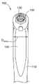
대략적으로 도 8a 내지 도 8c를 참조하면, 광대뼈의 치과용 임플란트(400)는 대략적으로 원통형의 본체(410), 내부 스레디드 보어(430), 비-회전 특징부(450) 및 비대칭 외부 특징부(420)를 포함한다. 대략적으로 원통형의 본체(410)는 제1 측면(410a) 및 제2 반대 측면(410b)을 갖는다. 또한, 대략적으로 원통형의 본체(410)는 대략적으로 근위 또는 치관측 부분(412a), 중간 부분(412b), 및 원위 또는 치근측 부분(412c)으로 나뉠 수 있다. 치근측 부분(412c)은 환자의 광대뼈에 광대뼈의 치과용 임플란트(400)를 고정시키기 위한 것이다.Referring generally to FIGS. 8A-8C , a
광대뼈의 치과용 임플란트(400)는, 광대뼈의 치과용 임플란트(400)가 비-광대뼈의 치과용 임플란트들 보다 상당히 길고, 이에 따라, 광대뼈의 치과용 임플란트(400)가 도 2에 도시된 광대뼈의 치과용 임플란트(100)와 동일하거나 유사한 방식으로 환자의 입 안의 광대뼈에 가까운 및/또는 광대뼈 내부의 위턱뼈 내로 설치될 수 있다는 점에서, 다른 치과용 임플란트들과 대략적으로 다르다. 광대뼈의 치과용 임플란트(400)는 많은 측면들에서 광대뼈의 치과용 임플란트(300)와 동일하거나 유사하다; 그러나, 광대뼈의 치과용 임플란트(400)는 주로, 광대뼈의 치과용 임플란트(300)의 대략적으로 평평한 특징부(360)와 같은 대략적으로 평평한 특징부를 포함하지 않는다는 점에서, 광대뼈의 치과용 임플란트(300)와 다르다. 이와 같이, 치관측 부분(412a) 및 중간 부분(412b)은 치관측 부분(312a) 및 중간 부분(312b)에 비해, 더 원통형이다.The
도 8a 내지 도 8c에 도시된 바와 같이, 광대뼈의 치과용 임플란트(400)는 대략적으로 원통형의 본체(410)의 치관측 부분(412a)과 치근측 부분(412c) 사이에 위치되는, 대략적으로 원통형의 본체(410)의 논-스레디드 중간 부분(412b)을 포함한다. 대안적으로, 논-스레디드 중간 부분(412b)의 전부 또는 일부는 하나 이상의 스레드들, 그루브들, 돌출부들, 또는 이들의 어떤 조합을 포함할 수 있다.8A-8C , the
치관측 부분(412a)은 복수의 원주 방향으로 연장되는 그루브들(412)을 포함하는, 그 외부 표면 둘레의 비대칭 외부 특징부(420)를 포함한다. 비대칭 외부 특징부(420)는 복수의 원주 방향으로 연장되는 그루브들 중 제1 부분(321a)과 같이 치근측으로 감소하는 복수의 원주 방향으로 연장되는 그루브들을 포함하지 않는다는 점을 제외하고, 비대칭 외부 특징부(420) 및 복수의 원주 방향으로 연장되는 그루브들(421)은 상술된 광대뼈의 치과용 임플란트(300)의 비대칭 외부 특징부(320) 및 복수의 원주 방향으로 연장되는 그루브들(321)과 동일하거나 유사하다. 오히려, 치근측 방향으로 복수의 원주 방향으로 연장되는 그루브들(421)에 인접하여, 광대뼈의 치과용 임플란트(400)의 본체(410) 둘레를 감싸는 스레드(422)가 있다. 일부 구현들에서, 치조골이 환자의 입 안의 적절한 영역에서 환자에게 있는 경우, 스레드(422)는 설치 동안 그러한 뼈에 광대뼈의 치과용 임플란트(400)를 확보하는 것을 돕는다.The
광대뼈의 치과용 임플란트(300)와 마찬가지로, 예를 들어, 광대뼈의 치과용 임플란트(400)는 광대뼈의 치과용 임플란트(100) 보다 상대적으로 더 큰 직경을 갖기 때문에, 광대뼈의 치과용 임플란트(100)의 논-그루브드 영역(125)과 같은 논-그루브드 영역을 포함하지 않고, 이에 따라, 내부 스레디드 보어(430)의 바닥부(431)(도 8c)는 광대뼈의 치과용 임플란트(400)의 제1 측면(410a)의 외부 표면으로부터 충분히 이격된다. 달리 말하면, 원주 방향으로 연장되는 벽(135)과 동일하거나 유사한, 내부 스레디드 보어(430)에 의해 형성되는 원주 방향으로 연장되는 벽(435)(도 8c)은, 복수의 원주 방향으로 연장되는 그루브들(421)이 쉽게 파손/스냅/파괴되지 않고, 제1 측면(410a)을 따라 그리고 내부 스레디드 보어(430)의 바닥부에 인접하여 연장되도록 허용하기에 충분한 최소 두께를 갖는다.As with the
일부 구현들에서, 복수의 원주 방향으로 연장되는 그루브들(421)의 각각의 원주 길이는 동일하거나, 상이하거나, 또는 이들의 조합이다. 예를 들어, 도 8b 및 도 9c에 가장 잘 도시된 바와 같이, 복수의 원주 방향으로 연장되는 그루브들(421)의 원주 길이는 복수의 원주 방향으로 연장되는 그루브들(321b) 중 제2 부분(321b)과 동일하거나 유사한 방식으로, 치근측으로 증가한다. 다시 말해, 복수의 원주 방향으로 연장되는 그루브들(421)의 단부들은 치근측 방향에서 외측으로 테이퍼진다.In some implementations, the circumferential length of each of the plurality of circumferentially extending
치근측 부분(412c)은 광대뼈의 치과용 임플란트(100)의 외부 스레드들(113)과 동일하거나 유사한, 그 외부 표면 둘레의 외부 스레드들(413)을 포함한다. 대략적으로 원통형의 본체(410)의 치근측 부분(412c)은 치근측 외부 스레드(413)를 가로지르는(예컨대, 끊음) 광대뼈의 치과용 임플란트(400)의 원주 둘레의 1열(417)의 이격된 복수의 대략적으로 수직인 플루트들(418)을 포함한다. 플루트들(418)은, (i) 환자의 뼈 소켓으로 광대뼈의 치과용 임플란트(400)를 셀프-태핑 및/또는 (ii) 설치 동안 광대뼈의 치과용 임플란트(400)를 수용하는 캐비티(예컨대, 뼈 소켓)로부터 배출될 재료의 경로를 제공하는 것에 의해, 광대뼈의 치과용 임플란트(400)의 설치를 돕는다. 단일 열 내에서 및/또는 하나 이상의 추가적인 열들(예컨대, 광대뼈의 치과용 임플란트(100)에서 2 열들의 플루트들(118)과 관련하여 상술된 바와 같음) 내에서, 더 많거나 더 적은 플루트들(418)이 고려되기도 한다.The
내부 스레디드 보어(430)는 광대뼈의 치과용 임플란트(400)의치관측 부분(412a) 내에 형성되고, 이는 상술된 광대뼈의 치과용 임플란트(300)의 내부 스레디드 보어(330)와 동일하거나 유사하다. 내부 스레디드 보어(430)는, 광대뼈의 치과용 임플란트(400) 상에 지대치(도시되지 않음) 및/또는 제2 픽스처(601b)(도 10c 및 도 10d에 도시되고, 아래에 설명됨)를 유지시키기 위해 제2 나사(602b)(도 10c 및 도 10d에 도시됨)와 나사 결합하도록, 그 내에 암 또는 내부 스레드(432)를 포함한다. 내부 스레디드 보어(430)는 내부 스레디드 보어(330)의 최대 깊이(DMAX)와 동일하거나 유사한 최대 깊이(DMAX)를 갖는다.The internally threaded
비-회전 특징부(450)는 대략적으로 치관측 부분(412a)으로부터 돌출되고, 내부 스레디드 보어(430)의 외부에 있으며, 상술된 광대뼈의 치과용 임플란트(300)의 비-회전 특징부(350)와 동일하거나 유사하다.The
광대뼈의 치과용 임플란트(400)의 대략적으로 원통형의 본체(410)는 메인-중심 축(Xmain)(도 8c)을 갖는다. 메인-중심 축(Xmain)은 광대뼈의 치과용 임플란트(400)의 대략적으로 원통형의 본체(410)의 적어도 치근측 부분(412c)와 중간 부분(412b)의 기하학적 중심 및/또는 대칭축을 통과하는 직선 축/선으로 정의된다. 그러나, 광대뼈의 치과용 임플란트(400)의 메인-중심 축(Xmain)은 대략적으로 원통형의 본체(410)의 치관측 부분(412a)의 대칭축을 통과하지 않는다(예컨대, 치관측 부분(412a)과 일치하지 않음). 이는, 광대뼈의 치과용 임플란트(400)의 대략적으로 원통형의 본체(410)의 치관측 부분(412a)이 (1) 광대뼈의 치과용 임플란트(400)의 메인-중심 축(Xmain)에 대해, 그리고 (2) 광대뼈의 치과용 임플란트(400)의 대략적으로 원통형의 본체(410)의 나머지에 대해 각지고/각지거나 오프셋된 각진 부분(414)(도 8a에 가장 잘 도시됨)을 포함하기 때문이다. 각진 부분(414)은 대략적으로 광대뼈의 치과용 임플란트(400)의 플랫폼으로 지칭된다. 적어도 광대뼈의 치과용 임플란트(400)는 광대뼈의 치과용 임플란트(400)의 각진 부분(414)에 비해 광대뼈의 치과용 임플란트(300)의 각진 부분(314)의 일부를 제거하는 대략적으로 평평한 특징부를 포함하지 않기 때문에, 각진 부분(414)이 상대적으로 더 크다는 점(예컨대, 동일한 공칭 사이즈의 광대뼈의 치과용 임플란트에 대해 더 많은 표면적을 포함함)을 제외하고, 각진 부분(414)은 광대뼈의 치과용 임플란트(300)의 각진 부분(314)과 동일하거나 유사하다. 플랫폼(314)과 플랫폼(414)에 대한 비교는 도 7a와 도 8a를 비교함으로써, 가장 잘 보여질 수 있다. 일부 구현들에서, 상대적으로 더 큰 플랫폼(414)은 플랫폼(314)에 비해, 상대적으로 더 큰 콤포넌트들이 플랫폼(414)과 결합/인접하게 한다.The generally
도 8c에 가장 잘 도시된 바와 같이, 내부 보어(830)는 보어-중심 축(Xbore)을 갖는다. 보어-중심 축(Xbore)은 광대뼈의 치과용 임플란트(400)의 적어도 내부 스레디드 보어(430)의 기하학적 중심 및/또는 대칭축을 통과하는 직선 축/선으로 정의된다. 내부 스레디드 보어(430)의 보어-중심 축(Xbore)은 광대뼈의 치과용 임플란트(400)의 메인-중심 축(Xmain)에 대해 상대적인 각도(θ)에 있다. 예를 들어, 각도(θ)는 약 7 도와 약 65 도 사이 또는 약 40 도와 약 65 도 사이와 같은 어떤 각도일 수 있다. 도8c에 도시된 바와 같이, 각도(θ)는 약 55 도이다.As best shown in FIG. 8C , the inner bore 830 has a bore-central axis Xbore . The bore-central axis (Xbore ) is defined as a straight axis/line passing through at least the geometric center of the internal threaded bore 430 of the
광대뼈의 치과용 임플란트(300)의 축들과 마찬가지로, 메인-중심 축(Xmain)과 보어-중심 축(Xbore)은 광대뼈의 치과용 임플란트(400)의 각진 부분 또는 플랫폼(414)에 의해 정의되는 평면(P)(도 8a 및 도 8c)을 따라 위치되는 한 지점(I)(도 7c)에서 교차한다. 일부 구현들에서, 광대뼈의 치과용 임플란트(400)에 대한 메인-중심 축(Xmain)과 보어-중심 축(Xbore)의 교차 지점(I)은 평면(P)로부터, 약 0.8 mm 이하, 약 0.7 mm 이하, 약 0.6 mm 이하, 약 0.5 mm 이하, 약 0.4 mm 이하, 약 0.3 mm 이하, 약 0.2 mm 이하, 약 0.1 mm 이하, 약 0.05 mm 이하 또는 약 0.025 mm 이하만큼, 이격된다. 일부 구현들에서, 광대뼈의 치과용 임플란트(400)에 대한 메인-중심 축(Xmain)과 보어-중심 축(Xbore)의 교차 지점(I)은 평면(P)으로부터, 약 0.0 mm와 약 0.8 mm 사이만큼, 약 0.0 mm와 약 0.6 mm 사이만큼, 약 0.0 mm와 약 0.5 mm 사이만큼, 약 0.0 mm와 약 0.3 mm 사이만큼, 약 0.0 mm와 약 0.1 mm 사이만큼, 이격된다.Like the axes of the
예시적인 일부 구현들에서, 비대칭 외부 특징부(420)는 2 mm와 10 mm 사이의, 메인-중심 축에 따른 전체 길이를 갖는다. 일부 구현들에서, 복수의 원주 방향으로 연장되는 그루브들(421)은 2 mm와 10 mm 사이의, 메인-중심 축에 따른 전체 길이를 갖는다. 일부 구현들에서, 스레드(422)는 3 mm와 14 mm 사이의, 메인-중심 축에 따른 전체 길이를 갖는다.In some example implementations, the asymmetric
광대뼈의 치과용 임플란트(400)는, 치관측 부분(412a)의 공칭 최대 외경인 4.3 mm의 치과용 임플란트로 지칭될 수 있다. 중간 및 치근측 부분들(412b 및 412c)의 공칭 최대 외경은 3.4 mm이다. 예를 들어, 3.0, 3.5, 4.0, 4.1, 4.2, 4.3, 4.4, 4.5, 4.6, 4.7, 4.8, 4.9, 5.0, 5.5, 6.0 등, 또는 그 사이의 어떤 사이즈와 같은, 치관측 부분(412a)의 다양한 다른 공칭 외경들이 광대뼈의 치과용 임플란트(400)에 대해 고려된다. 이와 유사하게, 예를 들어, 2.0, 2.5, 3.0, 3.1, 3.2, 3.3, 3.4, 3.5, 3.6, 3.7, 3.8, 3.9, 4.0, 4.1, 4.2, 4.3, 4.4, 4.5 등, 또는 그 사이의 어떤 사이즈와 같은, 중간 및 치근측 부분들(412b 및 412c)의 다양한 다른 공칭 외경들이 광대뼈의 치과용 임플란트(400)에 대해 고려된다.The
일부 구현들에서, 대략적으로 원통형의 본체(410)의 치관측 부분(412a)은 대략적으로 원통형의 본체(410)의 논-스레디드 중간 부분(412b)의 최대 외경 및 대략적으로 원통형의 본체(410)의 치근측 부분(412c)의 최대 외경 보다 상대적으로 더 큰 최대 외경을 갖는다. 대안적으로, 일부 구현들에서, 대략적으로 원통형의 본체(410)의 치관측 부분(412a)의 최대 외경은 대략적으로 원통형의 본체(410)의 논-스레디드 중간 부분(412b)의 최대 외경 및 대략적으로 원통형의 본체(410)의 치근측 부분(412c)의 최대 외경과 동일하거나 유사할 수 있다. 그러한 대안들에서, 전체 본체(410)의 외경은 대략적으로 일정할 수 있다(예컨대, 그루브들, 스레드들 등으로 인한 사소한 변화들은 제외함).In some implementations, the
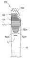
도 9a 내지 도 9f를 참조하면, 광대뼈의 치과용 임플란트(300)(도 9a 및 도 9b)의 치관측 부분(312a), 광대뼈의 치과용 임플란트(400)(도 9c 및 도 9d)의 치관측 부분(412a), 및 광대뼈의 치과용 임플란트(500)(도 9e 및 도 9f)의 치관측 부분(512a)은 메인-중심 축(Xmain)과 보어-중심 축(Xbore)의 교차들을 비교하기 위해 도시되고 있다. 상술된 바와 같이, 광대뼈의 치과용 임플란트들(300, 400)의 경우, 각진 부분(314, 414)에 의해 정의되는 평면(P) 상에 있는 지점(I)에서 교차가 발생한다. 그러나, 광대뼈의 치과용 임플란트(500)의 경우, 메인-중심 축(Xmain)과 보어-중심 축(Xbore)의 교차 지점(I)은 광대뼈의 치과용 임플란트(500)의 각진 부분 또는 플랫폼(514) 아래에서(below) 발생한다. 일부 구현들에서, 광대뼈의 치과용 임플란트(500)의 경우, 메인-중심 축(Xmain)과 보어-중심 축(Xbore)의 교차 지점(I)은 약 1.3 mm만큼 평면(P)으로부터 이격된다. 이와 같이, 광대뼈의 치과용 임플란트(500)의 내부 스레디드 보어(530)의 최대 깊이(DMAX)는 광대뼈의 치과용 임플란트들(300, 400)의 내부 보어들(330, 430)의 최대 깊이(DMAX) 보다 상대적으로 더 길다. 이는, 광대뼈의 치과용 임플란트의 내부 보어가 하부로/치근측으로(예컨대, 광대뼈의 치과용 임플란트의 가상적인(hypothetical) 설계에서) 이동됨에 따라, 상대적으로 더 깊은 내부 보어를 수용하기 위해 임플란트 본체에 더 많은 재료가 있기 때문이다(예컨대, 내부 보어/비-회전 특징부의 입구가 각진 부분/플랫폼을 하부로/치근측으로 슬라이드됨에 따라 너비 방향으로 더 많은 공간이 있음). 또한, 내부 보어가 하부로/치근측으로 이동됨에 따라, 메인-중심 축(Xmain)과 보어-중심 축(Xbore)의 교차 지점(I)도 하부로 이동한다. 상대적으로 더 깊은 내부 스레디드 보어(530)가 유리할 수 있지만(예컨대, 더 긴 나사들을 수용할 수 있음), 상대적으로 더 큰 헤드 또는 치관측 부분(512a)은 도 10a 내지 도 10f에 도시된 바와 같이 몇 가지 단점들을 가질 수 있다.Referring to FIGS. 9A-9F , the
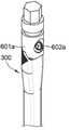
대략적으로 도10a 내지 도10f를 참조하면, 광대뼈의 치과용 임플란트들(300, 400, 500)에 부착되는 다양한 픽스처들(601a, 610b, 601c)이 비교를 위해 도시되어 있다. 즉, 이는, 보어-중심 축들(Xbore)과 상대적으로 더 높게/더 치관측으로(예컨대, 플랫폼(314, 414)에 의해 정의되는 평면(P) 상에서) 교차하는 메인-중심 축들(Xmain)을 갖는 광대뼈의 치과용 임플란트들(300, 400)이 상대적으로 더 좁은 픽스처(예컨대, 픽스처들(601a, 610b) 및/또는 광대뼈의 치과용 임플란트의 최대 외경 이하의 최대 외경을 갖는 픽스처를 허용한다는 것을 나타낸다. 이는, 비-회전 특징부 및 내부 보어가 상부로/치관측으로 이동됨에 따라(평면(P) 상 또는 근처에서 보어-중심 축(Xbore)과 교차하는 메인-중심 축(Xmain)을 야기할 수 있음), 상대적으로 더 작은 직경의 픽스처가 비-회전 특징부의 원주 둘레에 맞물리고 나사를 통해 광대뼈의 치과용 임플란트와 결합되도록 사용될 수 있기 때문이다.Referring roughly to FIGS. 10A-10F ,
도 10a 및 도 10b는 제1 나사(602a)를 통해 제1 픽스처(601a)에 결합되는 광대뼈의 치과용 임플란트(300)의 치관측 부분(312a)을 도시하고 있다. 도 10c 및 도 10d는 제2 나사(602b)를 통해 제2 픽스처(601b)에 결합되는 광대뼈의 치과용 임플란트(400)의 치관측 부분(412a)을 도시하고 있다. 상술된 바와 같이, 광대뼈의 치과용 임플란트들(300, 400) 둘 다의 경우, 메인-중심 축(Xmain)은 플랫폼(314, 414)(도 7c, 도 8c, 도 9b 및 도 9d)에 의해 정의되는 평면(P) 상의 지점(I)에서 보어-중심 축(Xbore)과 교차한다. 이 기하학적 구조는 픽스처들(601a, 601b)이 나사들(602a, 602b)을 통해 광대뼈의 치과용 임플란트(300, 400)에 각각 단단히 부착되고, 예를 들어 광대뼈의 치과용 임플란트(300, 400)의 최대 외경 및/또는 광대뼈의 치과용 임플란트(300, 400)의 치관측 부분(312a, 412a)의 최대 외경과 거의 동일한 최대 외경을 갖도록 허용한다.10A and 10B show the
비교를 통해, 도 10e 및 도 10f는 제3 나사(602c)를 통해 제3 픽스처(601c)에 결합되는 광대뼈의 치과용 임플란트(500)의 치관측 부분(512a)을 도시하고 있다. 도 9f에 가장 잘 도시되고 상술된 바와 같이, 광대뼈의 치과용 임플란트(500)의 경우, 메인-중심 축(Xmain)은 대략적으로 플랫폼(514)(도 9f에 도시됨)에 의해 정의되는 평면(P)으로부터 아래로 오프셋된 지점(I)에서 보어-중심 축(Xbore)과 교차한다. 제3 나사(602c)를 통해 광대뼈의 치과용 임플란트(500)에 단단히 부착되는 그러한 기하학적 구조의 경우, 제3 픽스처(601c)는 도 10e 및 도 10f에 도시된 바와 같이, 광대뼈의 치과용 임플란트(500)의 최대 외경 보다 더 큰 최대 외경을 필요로 한다.By way of comparison, FIGS. 10E and 10F show the
광대뼈의 치과용 임플란트의 최대 외경 이하인 최대 외경을 갖는 픽스처(예컨대, 광대뼈의 치과용 임플란트들(300, 400)과 각각 결합될 때의 제1 및 제 2 픽스처들(601a, b))를 갖는 것의 이점은, 그러한 픽스처가 주변 조직 및/또는 뼈에 부딪히는 픽스처의 위험, 및 픽스처가 광대뼈의 치과용 임플란트의 최대 외경 보다 더 큰 외경을 가질 때 존재하는 것과 같은 잠재적으로 존재하는 설치 프로세스 없이, 뼈 소켓에 광대뼈의 치과용 임플란트를 설치/구동시키는 데 사용될 수 있다는 것이다.of having a fixture having a maximum outer diameter that is less than or equal to the maximum outer diameter of the dental implant of the cheekbone (eg, the first and
광대뼈의 해부학적 구조는, 광대뼈의 치과용 임플란트들(100, 300, 400)이 약 20 mm와 약 70 mm 사이의 길이(L)를 갖는다는 것을 나타내며, 보다 상세하게는, 광대뼈의 해부학적 구조는, 광대뼈의 치과용 임플란트들(100, 300, 400)이 약 30 mm와 약 60 mm 사이의 길이(L)를 갖는다는 것을 나타낼 수 있다. 일부 구현들에서, 광대뼈의 해부학적 구조는, 광대뼈의 치과용 임플란트들(100, 300, 400)이 약 25 mm, 약 30 mm, 약 35 mm, 약 40 mm, 약 45 mm, 약 50 mm, 약 55 mm, 약 60 mm, 약 65 mm, 약 70 mm의 길이를 갖는다는 것을 나타낸다. 광대뼈의 치과용 임플란트들(100, 300, 400)의 그러한 길이(L)는 일반적으로 약 6 mm와 약 18 mm 사이의 길이를 갖는 비-광대뼈의 치과용 임플란트들 보다 상당히 더 길며, 보다 상세하게는 비-광대뼈의 치과용 임플란트들은 약 8 mm와 약 15 mm 사이의 길이를 갖는다.The anatomy of the cheekbone indicates that the
논-스레디드 중간 부분들(112b, 312b, 412b)의 각각은 광대뼈의 치과용 임플란트(100, 300, 400)의 총 길이의 약 20 퍼센트와 약 70 퍼센트 사이인 길이를 각각 갖는다. 더 바람직하게는, 논-스레디드 중간 부분들(112b, 312b, 412b)의 각각은 광대뼈의 치과용 임플란트(100, 300, 400)의 총 길이의 약 35 퍼센트와 약 55 퍼센트 사이인 길이를 각각 갖는다. 일부 구현들에서, 논-스레디드 중간 부분들(112b, 312b, 412b)의 각각은 광대뼈의 치과용 임플란트(100,300, 400)의 총 길이의 약 45 퍼센트인 길이를 각각 갖는다.Each of the non-threaded
본 개시는 하나 이상의 특정 실시예들 및 구현들을 참조하여 설명되었지만, 해당 기술 분야에서 통상의 지식을 가진 자는 본 개시의 사상 및 범위를 벗어나지 않고 많은 변경이 이루어질 수 있음을 인식할 것이다. 이러한 실시예들 및 구현들과 그들의 명백한 변형들의 각각은 청구범위에서 설정되는 본 개시의 사상 및 범위 내에 있는 것으로 고려된다.While the present disclosure has been described with reference to one or more specific embodiments and implementations, those skilled in the art will recognize that many changes may be made without departing from the spirit and scope of the present disclosure. Each of these embodiments and implementations and their obvious variations is considered to be within the spirit and scope of the present disclosure as set forth in the claims.
Claims (48)
Translated fromKorean치관측 부분 및 치근측 부분을 갖는 원통형의 본체 - 상기 치근측 부분은 환자의 광대뼈에 상기 광대뼈의 치과용 임플란트를 고정시키기 위한 것이고, 상기 원통형의 본체는 메인-중심 축을 가짐 -;
상기 광대뼈의 치과용 임플란트와 맞물리는 지대치를 제거 가능하게 유지시키도록 구성되는 나사를 수용하기 위해, 상기 원통형의 본체의 상기 치관측 부분 내에 형성되는 내부 스레디드 보어 - 상기 내부 스레디드 보어는 보어-중심 축을 가짐 -; 및
상기 원통형의 본체의 제1 측면의 적어도 일부 상의 비대칭 외부 특징부 - 이에 따라, 상기 비대칭 외부 특징부는 상기 환자의 치조골과 직접 맞물리도록 구성되고, 상기 비대칭 외부 특징부는 복수의 원주 방향으로 연장되는 그루브들을 포함함 -
를 포함하고,
상기 복수의 원주 방향으로 연장되는 그루브들 중 제1 부분의 단부들(ends)은, 치근측 방향(apical direction)에서 내측으로 테이퍼지고(taper),
상기 복수의 원주 방향으로 연장되는 그루브들 중 제2 부분의 단부들은, 상기 치근측 방향에서 외측에서 테이퍼지는,
광대뼈의 치과용 임플란트.
In the dental implant of the cheekbone,
a cylindrical body having a coronal portion and an apical portion, said apical portion for fixing a dental implant of said cheekbone to a cheekbone of a patient, said cylindrical body having a main-central axis;
an internally threaded bore formed in the coronal portion of the cylindrical body to receive a screw configured to removably retain an abutment for engaging a dental implant in the cheekbone, the internally threaded bore being having a central axis -; and
An asymmetric external feature on at least a portion of a first side of the cylindrical body, such that the asymmetric external feature is configured to engage directly with the alveolar bone of the patient, the asymmetric external feature comprising a plurality of circumferentially extending grooves Included -
including,
ends of a first portion of the plurality of circumferentially extending grooves are inwardly tapered in an apical direction;
Ends of a second portion of the plurality of circumferentially extending grooves are tapered outwardly in the apical direction,
Dental implants in the cheekbones.
상기 보어-중심 축은 상기 원통형의 본체의 상기 메인-중심 축에 대해 상대적인 0이 아닌 각도에 있는,
광대뼈의 치과용 임플란트.
12. The method of claim 11,
wherein the bore-central axis is at a non-zero angle relative to the main-central axis of the cylindrical body;
Dental implants in the cheekbones.
상기 원통형의 본체의 외부 표면의 적어도 일부와 상기 내부 스레디드 보어의 내부 표면의 적어도 일부는, 함께 원주 방향으로 연장되는 벽을 정의하고,
상기 보어-중심 축은, 상기 원통형의 본체의 상기 메인-중심 축에 대해 상대적인 각도에 있고,
상기 보어-중심 축의 상기 상대적인 각도는, 상기 원주 방향으로 연장되는 벽의 적어도 제1 부분이 상기 원주 방향으로 연장되는 벽의 상기 제1 부분의 원주에 대해 다양한 두께를 갖게 하는,
광대뼈의 치과용 임플란트.
12. The method of claim 11,
at least a portion of the outer surface of the cylindrical body and at least a portion of the inner surface of the inner threaded bore together define a circumferentially extending wall;
the bore-central axis is at an angle relative to the main-central axis of the cylindrical body;
wherein the relative angle of the bore-central axis causes at least a first portion of the circumferentially extending wall to have a varying thickness with respect to a circumference of the first portion of the circumferentially extending wall;
Dental implants in the cheekbones.
상기 복수의 원주 방향으로 연장되는 그루브들 중 일부의 원주 길이는, 치근측으로 감소하고,
상기 복수의 원주 방향으로 연장되는 그루브들 중 치근측으로 감소하는 일부의 상기 메인-중심 축에 따른 길이에 대한 상기 원통형의 본체의 상기 메인-중심 축에 따른 길이의 비는,
5와 35 사이인,
광대뼈의 치과용 임플란트.
12. The method of claim 11,
The circumferential length of some of the plurality of circumferentially extending grooves is decreased to the root side,
A ratio of a length along the main-central axis of the cylindrical body to a length along the main-central axis of some of the plurality of circumferentially extending grooves that decrease apically,
between 5 and 35,
Dental implants in the cheekbones.
상기 복수의 원주 방향으로 연장되는 그루브들 중 일부의 각각은, 갭을 포함하고, 이에 따라 갭들이 논-그루브드 영역을 공동으로 정의하고,
상기 정의된 논-그루브드 영역은, 상기 원통형의 본체의 원주 방향으로 연장되는 벽의 가장 얇은 부분에 인접하고,
상기 원주 방향으로 연장되는 벽은, 상기 원통형의 본체의 외부 표면의 적어도 일부와 상기 내부 스레디드 보어의 내부 표면의 적어도 일부에 의해 정의되는,
광대뼈의 치과용 임플란트.
12. The method of claim 11,
each of some of the plurality of circumferentially extending grooves includes a gap, such that the gaps jointly define a non-grooved region;
The defined non-grooved region is adjacent to the thinnest part of the circumferentially extending wall of the cylindrical body,
wherein the circumferentially extending wall is defined by at least a portion of an outer surface of the cylindrical body and at least a portion of an inner surface of the inner threaded bore;
Dental implants in the cheekbones.
상기 제1 측면에 반대되는 상기 원통형의 본체의 제2 측면 상의 평평한 특징부 - 이에 따라, 상기 평평한 특징부는 상기 환자의 연조직에 맞물리도록 구성됨 -
를 더 포함하는, 광대뼈의 치과용 임플란트.
12. The method of claim 11,
a flat feature on a second side of the cylindrical body opposite the first side, such that the flat feature is configured to engage soft tissue of the patient
Further comprising, dental implants of the cheekbones.
상기 복수의 원주 방향으로 연장되는 그루브들 중 상기 제 2 부분의 하나 이상은,
논-그루브드 영역을 정의하는 중앙에 위치되는 갭을 포함하는, 광대뼈의 치과용 임플란트.
12. The method of claim 11,
At least one of the second portion of the plurality of circumferentially extending grooves,
A dental implant of the cheekbone comprising a centrally located gap defining a non-grooved region.
(i) 비-회전 방식으로 상기 지대치와 맞물리거나, (ii) 비-회전 방식으로 상기 광대뼈의 치과용 임플란트를 설치하기 위해 사용되는 픽스처 마운트와 맞물리거나, (iii) (i)과 (ii) 둘 다를 위해 구성되는 비-회전 특징부
를 더 포함하는, 광대뼈의 치과용 임플란트.
12. The method of claim 11,
(i) engaging the abutment in a non-rotational manner, (ii) engaging a fixture mount used to install a dental implant of the cheekbone in a non-rotating manner, or (iii) (i) and (ii) Non-rotating features configured for both
Further comprising, dental implants of the cheekbones.
상기 비대칭 외부 특징부는,
시프트되는(shifted) 비대칭 외부 특징부인, 광대뼈의 치과용 임플란트.
12. The method of claim 11,
The asymmetric external feature comprises:
A dental implant of the cheekbone, which is a shifted asymmetric external feature.
치관측 부분 및 치근측 부분을 갖는 원통형의 본체 - 상기 치근측 부분은 환자의 광대뼈에 상기 광대뼈의 치과용 임플란트를 고정시키기 위한 것이고, 상기 치관측 부분은 플랫폼(platform)을 포함하고, 상기 원통형의 본체는 메인-중심 축을 가짐 -;
상기 플랫폼으로부터 연장되는 비-회전 특징부;
소켓(socket) 내에 상기 광대뼈의 치과용 임플란트를 설치하는 데 사용하기 위해 상기 광대뼈의 치과용 임플란트와 맞물리는 픽스처(fixture)를 제거 가능하게 유지시키도록 구성되는 나사를 수용하기 위해, 상기 원통형의 본체의 상기 치관측 부분 내에 형성되는 내부 스레디드 보어 - 상기 내부 스레디드 보어는 (i) 상기 플랫폼에 의해 정의되는 평면에 수직이고, (ii) 상기 원통형의 본체의 상기 메인-중심 축에 대해 상대적인 0이 아닌 각도에 있는 보어-중심 축을 갖고, 상기 보어-중심 축은 상기 플랫폼에 의해 정의되는 상기 평면 내의 한 지점(point)에서 상기 원통형의 본체의 상기 메인-중심 축과 교차함 -; 및
상기 원통형의 본체의 제1 측면의 적어도 일부 상의 비대칭 외부 특징부 - 이에 따라, 상기 비대칭 외부 특징부는 상기 환자의 치조골과 직접 맞물리도록 구성되고, 상기 비대칭 외부 특징부는 복수의 원주 방향으로 연장되는 그루브들을 포함함 -
를 포함하는, 광대뼈의 치과용 임플란트.
In the dental implant of the cheekbone,
A cylindrical body having a coronal portion and an apical portion, wherein the apical portion is for fixing a dental implant of the cheekbone to a cheekbone of a patient, the coronal portion comprising a platform, the cylindrical the body has a main-central axis;
a non-rotating feature extending from the platform;
to receive a screw configured to removably retain a fixture for engaging the dental implant of the cheekbone for use in installing the dental implant of the cheekbone in a socket; an internally threaded bore formed in said coronal portion of said body, said internally threaded bore being (i) perpendicular to a plane defined by said platform and (ii) relative to said main-central axis of said cylindrical body having a bore-central axis at a non-zero angle, wherein the bore-central axis intersects the main-central axis of the cylindrical body at a point in the plane defined by the platform; and
An asymmetric external feature on at least a portion of a first side of the cylindrical body, such that the asymmetric external feature is configured to engage directly with the alveolar bone of the patient, the asymmetric external feature comprising a plurality of circumferentially extending grooves Included -
Containing, dental implants of the cheekbones.
상기 복수의 원주 방향으로 연장되는 그루브들 중 제 1 부분의 원주 길이는, 치근측으로 증가하고,
상기 복수의 원주 방향으로 연장되는 그루브들 중 제2 부분의 원주 길이는, 치근측으로 감소하는,
광대뼈의 치과용 임플란트.
32. The method of claim 31,
The circumferential length of a first portion of the plurality of circumferentially extending grooves increases apically,
The circumferential length of a second portion of the plurality of circumferentially extending grooves decreases apically,
Dental implants in the cheekbones.
상기 제1 측면에 반대되는 상기 원통형의 본체의 제2 측면 상의 평평한 특징부 - 이에 따라, 상기 평평한 특징부는 상기 환자의 연조직과 맞물리도록 구성됨 -
를 더 포함하고,
상기 평평한 특징부는, 치근측 방향으로 상기 플랫폼으로부터 연장되는,
광대뼈의 치과용 임플란트.
32. The method of claim 31,
a flat feature on a second side of the cylindrical body opposite the first side, such that the flat feature is configured to engage soft tissue of the patient
further comprising,
wherein the planar feature extends from the platform in a apical direction,
Dental implants in the cheekbones.
상기 메인-중심 축에 따른 상기 평평한 특징부의 길이는,
상기 광대뼈의 치과용 임플란트의 길이의 50 퍼센트와 75 퍼센트 사이인, 광대뼈의 치과용 임플란트.
35. The method of claim 34,
The length of the planar feature along the main-central axis is
between 50 percent and 75 percent of the length of the dental implant in the cheekbone.
상기 광대뼈의 치과용 임플란트는,
상기 픽스처와 결합되고,
상기 픽스처는,
상기 광대뼈의 치과용 임플란트의 최대 외경(outer diameter) 이하인 최대 외경을 갖는,
광대뼈의 치과용 임플란트.
32. The method of claim 31,
The dental implant of the cheekbone,
combined with the fixture,
The fixture is
having a maximum outer diameter that is less than or equal to the maximum outer diameter of the dental implant of the cheekbone,
Dental implants in the cheekbones.
치관측 부분 및 치근측 부분을 갖는 원통형의 본체 - 상기 치근측 부분은 환자의 광대뼈에 상기 광대뼈의 치과용 임플란트를 고정시키기 위한 것이고, 상기 원통형의 본체는 메인-중심 축을 가짐 -;
상기 광대뼈의 치과용 임플란트와 맞물리는 지대치를 제거 가능하게 유지시키도록 구성되는 나사를 수용하기 위해, 상기 원통형의 본체의 상기 치관측 부분 내에 형성되는 내부 스레디드 보어 - 상기 내부 스레디드 보어는 보어-중심 축을 가짐 -; 및
상기 원통형의 본체의 제1 측면의 적어도 일부 상의 비대칭 외부 특징부 - 이에 따라, 상기 비대칭 외부 특징부는 상기 환자의 치조골과 직접 맞물리도록 구성되고, 상기 비대칭 외부 특징부는 복수의 원주 방향으로 연장되는 그루브들을 포함함 -
를 포함하고,
상기 복수의 원주 방향으로 연장되는 그루브들 중 일부의 원주 길이는, 치근측으로 증가하고,
상기 복수의 원주 방향으로 연장되는 그루브들 중 치근측으로 증가하는 일부의 상기 메인-중심 축에 따른 길이에 대한 상기 원통형의 본체의 상기 메인-중심 축에 따른 길이의 비는, 5와 35 사이인,
광대뼈의 치과용 임플란트.
In the dental implant of the cheekbone,
a cylindrical body having a coronal portion and an apical portion, said apical portion for fixing a dental implant of said cheekbone to a cheekbone of a patient, said cylindrical body having a main-central axis;
an internally threaded bore formed in the coronal portion of the cylindrical body to receive a screw configured to removably retain an abutment for engaging a dental implant in the cheekbone, the internally threaded bore being having a central axis -; and
An asymmetric external feature on at least a portion of a first side of the cylindrical body, such that the asymmetric external feature is configured to engage directly with the alveolar bone of the patient, the asymmetric external feature comprising a plurality of circumferentially extending grooves Included -
including,
The circumferential length of some of the plurality of circumferentially extending grooves increases apically,
a ratio of a length along the main-central axis of the cylindrical body to a length along the main-central axis of a portion of the plurality of circumferentially extending grooves that increases apically is between 5 and 35;
Dental implants in the cheekbones.
상기 보어-중심 축은 상기 원통형의 본체의 상기 메인-중심 축에 대해 상대적인 0이 아닌 각도에 있는,
광대뼈의 치과용 임플란트.
44. The method of claim 43,
wherein the bore-central axis is at a non-zero angle relative to the main-central axis of the cylindrical body;
Dental implants in the cheekbones.
상기 원통형의 본체의 외부 표면의 적어도 일부와 상기 내부 스레디드 보어의 내부 표면의 적어도 일부는, 함께 원주 방향으로 연장되는 벽을 정의하고,
상기 보어-중심 축은, 상기 원통형의 본체의 상기 메인-중심 축에 대해 상대적인 각도에 있고,
상기 보어-중심 축의 상기 상대적인 각도는, 상기 원주 방향으로 연장되는 벽의 적어도 제1 부분이 상기 원주 방향으로 연장되는 벽의 상기 제1 부분의 원주에 대해 다양한 두께를 갖게 하는,
광대뼈의 치과용 임플란트.
44. The method of claim 43,
at least a portion of the outer surface of the cylindrical body and at least a portion of the inner surface of the inner threaded bore together define a circumferentially extending wall;
the bore-central axis is at an angle relative to the main-central axis of the cylindrical body;
wherein the relative angle of the bore-central axis causes at least a first portion of the circumferentially extending wall to have a varying thickness with respect to a circumference of the first portion of the circumferentially extending wall;
Dental implants in the cheekbones.
상기 제1 측면에 반대되는 상기 원통형의 본체의 제2 측면 상의 평평한 특징부 - 이에 따라, 상기 평평한 특징부는 상기 환자의 연조직에 맞물리도록 구성됨 -
를 더 포함하는, 광대뼈의 치과용 임플란트.
44. The method of claim 43,
a flat feature on a second side of the cylindrical body opposite the first side, such that the flat feature is configured to engage soft tissue of the patient
Further comprising, dental implants of the cheekbones.
상기 복수의 원주 방향으로 연장되는 그루브들 중 하나 이상은,
논-그루브드 영역을 정의하는 중앙에 위치되는 갭을 포함하는, 광대뼈의 치과용 임플란트.
44. The method of claim 43,
At least one of the plurality of circumferentially extending grooves,
A dental implant of the cheekbone comprising a centrally located gap defining a non-grooved region.
(i) 비-회전 방식으로 상기 지대치와 맞물리거나, (ii) 비-회전 방식으로 상기 광대뼈의 치과용 임플란트를 설치하기 위해 사용되는 픽스처 마운트와 맞물리거나, (iii) (i)과 (ii) 둘 다를 위해 구성되는 비-회전 특징부
를 더 포함하는, 광대뼈의 치과용 임플란트.44. The method of claim 43,
(i) engaging the abutment in a non-rotational manner, (ii) engaging a fixture mount used to install a dental implant of the cheekbone in a non-rotating manner, or (iii) (i) and (ii) Non-rotating features configured for both
Further comprising, dental implants of the cheekbones.
Applications Claiming Priority (3)
| Application Number | Priority Date | Filing Date | Title |
|---|---|---|---|
| US201862633481P | 2018-02-21 | 2018-02-21 | |
| US62/633,481 | 2018-02-21 | ||
| PCT/IB2019/051344WO2019162836A1 (en) | 2018-02-21 | 2019-02-19 | Asymmetric zygomatic dental implant with partial micro thread/groove |
Publications (2)
| Publication Number | Publication Date |
|---|---|
| KR20200128047A KR20200128047A (en) | 2020-11-11 |
| KR102462085B1true KR102462085B1 (en) | 2022-11-01 |
Family
ID=65818049
Family Applications (1)
| Application Number | Title | Priority Date | Filing Date |
|---|---|---|---|
| KR1020207026809AActiveKR102462085B1 (en) | 2018-02-21 | 2019-02-19 | Dental implants of asymmetric cheekbones with partial micro-threads/grooves |
Country Status (8)
| Country | Link |
|---|---|
| US (4) | US11278379B2 (en) |
| EP (2) | EP4108208B1 (en) |
| KR (1) | KR102462085B1 (en) |
| CN (1) | CN111867513B (en) |
| BR (1) | BR112020017064B1 (en) |
| ES (1) | ES2930901T3 (en) |
| IL (2) | IL276785B2 (en) |
| WO (1) | WO2019162836A1 (en) |
Families Citing this family (16)
| Publication number | Priority date | Publication date | Assignee | Title |
|---|---|---|---|---|
| US9125708B2 (en) | 2008-07-09 | 2015-09-08 | Nobel Biocare Services Ag | Medical implant and method of implantation |
| ES2779803T3 (en) | 2016-03-30 | 2020-08-19 | Southern Implants (Pty) Ltd | Angled dental implant |
| US20210236247A1 (en)* | 2018-05-03 | 2021-08-05 | João Manuel MENDES CARAMÊS | Medical implant and medical implant system for malar process of the maxilla |
| BR202019001133U2 (en)* | 2019-01-21 | 2020-08-04 | Jjgc Indústria E Comércio De Materiais Dentários S.A. | ZYGOMATIC IMPLANT WITH PARTIALLY INTERRUPTED THREADED PORTION |
| US11141245B2 (en)* | 2019-02-07 | 2021-10-12 | Dan Rosen | Angled dental implant with angled anchor point |
| FR3102355A1 (en)* | 2019-10-24 | 2021-04-30 | Gérard Scortecci | Guided anatomical oblique transverse implant |
| JP7511311B2 (en)* | 2020-04-02 | 2024-07-05 | マイケル ワセフ | HORIZONTALLY POSITIONED ENDOSTEEL DENTAL IMPLANT SYSTEM AND METHOD - Patent application |
| CN111419449A (en)* | 2020-04-29 | 2020-07-17 | 上海交通大学医学院附属第九人民医院 | Cheekbone-wearing implant and oral implant |
| RU2750440C1 (en)* | 2020-07-03 | 2021-06-28 | Михаил Владимирович Гладышев | Method for installing zygomatic implants |
| RU2746826C1 (en)* | 2020-07-28 | 2021-04-21 | Федеральное государственное бюджетное учреждение национальный медицинский исследовательский центр "Центральный научно-исследовательский институт стоматологии и челюстно-лицевой хирургии" Министерства здравоохранения Российской Федерации (ФГБУ НМИЦ "ЦНИИСиЧЛХ" Минздрава России) | Method of prosthetics for an atrophied upper jaw and a zygomatic implant for its implementation |
| CN112826618B (en)* | 2020-12-31 | 2022-10-18 | 中国人民解放军陆军军医大学第二附属医院 | Bent cheekbone-passing implant structure |
| CN113786256B (en)* | 2021-11-17 | 2022-02-08 | 极限人工智能有限公司 | Implant safety zone generation method and device, electronic equipment and storage medium |
| WO2024073799A1 (en)* | 2022-10-05 | 2024-04-11 | Alex Fibishenko | Zygomatic dental implant |
| KR102803692B1 (en)* | 2022-10-21 | 2025-05-12 | (주)엠지뉴턴 | Dental implant fixture and implant system having the same |
| WO2024167436A1 (en)* | 2023-02-08 | 2024-08-15 | ЧЕРНОВОЛ, Елизавета Михайловна | Orthopaedic device with integrated tension screw for a dental implant |
| WO2025091098A1 (en)* | 2023-10-30 | 2025-05-08 | Camargo Vanderlim Branco | Transnasal dental implant |
Citations (3)
| Publication number | Priority date | Publication date | Assignee | Title |
|---|---|---|---|---|
| WO2012164560A1 (en) | 2011-06-02 | 2012-12-06 | Yuval Jacoby | Dental implant |
| JP6133549B2 (en) | 2012-04-26 | 2017-05-24 | 新光電気工業株式会社 | Wiring board and method of manufacturing wiring board |
| US20170281320A1 (en) | 2016-03-30 | 2017-10-05 | Southern Implants (Pty) Ltd | Angulated dental implant |
Family Cites Families (40)
| Publication number | Priority date | Publication date | Assignee | Title |
|---|---|---|---|---|
| US4463753A (en)* | 1980-01-04 | 1984-08-07 | Gustilo Ramon B | Compression bone screw |
| US5573401A (en) | 1989-12-21 | 1996-11-12 | Smith & Nephew Richards, Inc. | Biocompatible, low modulus dental devices |
| DE9017101U1 (en)* | 1990-12-19 | 1991-04-11 | Gerhard Hug Gmbh, 7801 Umkirch | Bone screw |
| US5564926A (en) | 1992-11-26 | 1996-10-15 | Medevelop Ab | Anchoring element for anchorage in bone tissue |
| SE500383C2 (en)* | 1992-11-26 | 1994-06-13 | Medevelop Ab | Double anchored tooth fixture |
| US5573404A (en) | 1994-02-01 | 1996-11-12 | Stawski, Ii; Willard S. | Device and process for modifying behavior of children |
| ES2171112B1 (en)* | 2000-03-22 | 2003-10-16 | Micerium S R L | SCREW FOR DENTAL IMPLANTS. |
| US6511481B2 (en)* | 2001-03-30 | 2003-01-28 | Triage Medical, Inc. | Method and apparatus for fixation of proximal femoral fractures |
| EP1482856A1 (en)* | 2002-03-06 | 2004-12-08 | A.J.S. Dawood | A fixture for orthodontic anchorage and osseo distraction of the alveolar process, and for the stabilization of temporary prostheses |
| SE528324C2 (en)* | 2004-02-02 | 2006-10-17 | Braanemark Integration Ab | Fixture as well as tooth fixing elements and tooth fasteners |
| SE528719C2 (en)* | 2005-06-03 | 2007-01-30 | Nobel Biocare Services Ag | Device for implants extending between a dental installation and the zygoma |
| US8540510B2 (en)* | 2006-05-04 | 2013-09-24 | Nobel Biocare Services Ag | Device for securing a dental implant in bone tissue, a method for making a surgical template and a method of securing a dental implant in bone tissue |
| BRMU8700304Y8 (en) | 2007-03-05 | 2021-06-22 | Geninho Thome | zygomatic implant with internal connection through a conical-shaped cavity (morse cone) |
| BRPI0705570B8 (en)* | 2007-05-24 | 2021-06-22 | Itp Inst De Tecnologia E Pesquisa Ltda | compensatory correction system for inclinations, converters and extenders and universal coupling abutments on osseointegrated implants |
| WO2008157137A1 (en) | 2007-06-14 | 2008-12-24 | Southern Implants, Inc. | Dental implant system for use with coaxially non-aligned prosthesis |
| US20110027756A1 (en)* | 2008-05-21 | 2011-02-03 | Jean Benatouil | One-piece inclined dental implant |
| US9125708B2 (en)* | 2008-07-09 | 2015-09-08 | Nobel Biocare Services Ag | Medical implant and method of implantation |
| US8616881B2 (en)* | 2009-06-30 | 2013-12-31 | Dental Design Consultants, Llc | Modified asymmetrical dental implant |
| CN201727594U (en) | 2010-04-22 | 2011-02-02 | 陈俊龙 | One Piece Angled Implants |
| EP2407120A1 (en) | 2010-07-14 | 2012-01-18 | Nobel Biocare Services AG | Implant system |
| US20120077151A1 (en)* | 2010-09-24 | 2012-03-29 | Nary Filho Hugo | Morse Taper Dental Implant |
| US20120178048A1 (en)* | 2011-01-11 | 2012-07-12 | Cottrell Richard D | Dental implant with multiple thread patterns |
| US9039765B2 (en)* | 2011-01-21 | 2015-05-26 | Warsaw Orhtopedic, Inc. | Implant system and method for stabilization of a sacro-iliac joint |
| US20120237899A1 (en)* | 2011-03-03 | 2012-09-20 | Astra Tech Ab | Dental implant assembly |
| TW201238570A (en) | 2011-03-22 | 2012-10-01 | Riemser Arzneimittel Ag | Dental implant having a first conical screw part and a second cylindrical screw part |
| EP2510899A1 (en)* | 2011-04-14 | 2012-10-17 | Astra Tech AB | Fixture |
| EP2732791B1 (en) | 2011-07-11 | 2019-03-06 | Neobiotech Co., Ltd. | Angular friction joint type of dental implant |
| EP2570095A1 (en)* | 2011-09-14 | 2013-03-20 | Dentsply IH AB | A dental component and a dental implant |
| US20140272794A1 (en) | 2013-03-15 | 2014-09-18 | Clarion University of Pennsylvania | Surface modified dental implant |
| EP3134025A4 (en) | 2014-04-22 | 2018-01-10 | T.A.G. Medical Devices - Agriculture Cooperative Ltd. | Dental implants |
| US20160015483A1 (en)* | 2014-04-30 | 2016-01-21 | Osseodyne Surgical Solutions, LLC. | Osseointegrative surgical implant |
| EP3169267B1 (en)* | 2014-07-17 | 2018-12-19 | Southern Implants (Pty) Ltd. | Overdenture retention implant |
| US10869739B2 (en) | 2014-09-05 | 2020-12-22 | Greg Miller | Dental implant |
| EP3106121A1 (en)* | 2015-06-19 | 2016-12-21 | Nobel Biocare Services AG | Placement device for a dental component |
| IL263449B (en)* | 2016-06-14 | 2022-09-01 | Southern Implants Pty Ltd | Main body dental implant with reverse taper for anterior sockets after extraction |
| CN106725933A (en)* | 2016-12-23 | 2017-05-31 | 大连三生科技发展有限公司 | A kind of ceramic anti-rotation Angled abutment implant system |
| CN106491225A (en)* | 2016-12-23 | 2017-03-15 | 大连三生科技发展有限公司 | Implant system based on titanium-zirconium alloy |
| US11191645B2 (en)* | 2017-09-05 | 2021-12-07 | ExsoMed Corporation | Small bone tapered compression screw |
| US20210236247A1 (en)* | 2018-05-03 | 2021-08-05 | João Manuel MENDES CARAMÊS | Medical implant and medical implant system for malar process of the maxilla |
| EP3883495B1 (en)* | 2018-11-23 | 2025-01-08 | Nobel Biocare Services AG | Multi-part implant |
- 2019
- 2019-02-19KRKR1020207026809Apatent/KR102462085B1/enactiveActive
- 2019-02-19ILIL276785Apatent/IL276785B2/enunknown
- 2019-02-19CNCN201980014743.5Apatent/CN111867513B/enactiveActive
- 2019-02-19WOPCT/IB2019/051344patent/WO2019162836A1/ennot_activeCeased
- 2019-02-19BRBR112020017064-0Apatent/BR112020017064B1/enactiveIP Right Grant
- 2019-02-19ILIL310554Apatent/IL310554B2/enunknown
- 2019-02-19USUS16/279,632patent/US11278379B2/enactiveActive
- 2019-02-19EPEP22189441.3Apatent/EP4108208B1/enactiveActive
- 2019-02-19EPEP19712028.0Apatent/EP3755264B1/enactiveActive
- 2019-02-19ESES19712028Tpatent/ES2930901T3/enactiveActive
- 2021
- 2021-07-13USUS29/799,251patent/USD952856S1/enactiveActive
- 2022
- 2022-03-14USUS17/693,796patent/US12004920B2/enactiveActive
- 2024
- 2024-06-06USUS18/736,200patent/US20240325122A1/enactivePending
Patent Citations (3)
| Publication number | Priority date | Publication date | Assignee | Title |
|---|---|---|---|---|
| WO2012164560A1 (en) | 2011-06-02 | 2012-12-06 | Yuval Jacoby | Dental implant |
| JP6133549B2 (en) | 2012-04-26 | 2017-05-24 | 新光電気工業株式会社 | Wiring board and method of manufacturing wiring board |
| US20170281320A1 (en) | 2016-03-30 | 2017-10-05 | Southern Implants (Pty) Ltd | Angulated dental implant |
Also Published As
| Publication number | Publication date |
|---|---|
| US12004920B2 (en) | 2024-06-11 |
| CN111867513B (en) | 2022-04-26 |
| CN111867513A (en) | 2020-10-30 |
| IL276785B1 (en) | 2024-03-01 |
| US20240325122A1 (en) | 2024-10-03 |
| KR20200128047A (en) | 2020-11-11 |
| IL310554B2 (en) | 2025-02-01 |
| US20220202541A1 (en) | 2022-06-30 |
| USD952856S1 (en) | 2022-05-24 |
| BR112020017064A2 (en) | 2020-12-22 |
| EP4108208B1 (en) | 2024-05-08 |
| IL310554A (en) | 2024-03-01 |
| EP3755264B1 (en) | 2022-08-31 |
| US11278379B2 (en) | 2022-03-22 |
| ES2930901T3 (en) | 2022-12-22 |
| EP4108208A1 (en) | 2022-12-28 |
| US20190254781A1 (en) | 2019-08-22 |
| EP4108208C0 (en) | 2024-05-08 |
| IL276785A (en) | 2020-10-29 |
| IL276785B2 (en) | 2024-07-01 |
| IL310554B1 (en) | 2024-10-01 |
| BR112020017064B1 (en) | 2024-01-23 |
| WO2019162836A1 (en) | 2019-08-29 |
| EP3755264A1 (en) | 2020-12-30 |
Similar Documents
| Publication | Publication Date | Title |
|---|---|---|
| KR102462085B1 (en) | Dental implants of asymmetric cheekbones with partial micro-threads/grooves | |
| JP5275460B2 (en) | Medical implant and method of implantation | |
| AU2010266567B2 (en) | Modified asymmetrical dental implant | |
| EP2713939B1 (en) | Dental implant | |
| US11523883B2 (en) | Dental implant having reverse-tapered main body for anterior post-extraction sockets | |
| US20050208453A1 (en) | Attachment mechanism for dental implants | |
| KR20110033853A (en) | Improved Fixture for Detachable Dental Implants | |
| US20140030674A1 (en) | Prefabricated immediate no-drill dental implant | |
| US8992222B2 (en) | Ridge lap dental implant | |
| WO2008157138A2 (en) | Dental implant for asymmetrical abutment mounting | |
| EP3291759B1 (en) | Dental implant | |
| RU161879U1 (en) | SCREW DENTAL IMPLANT | |
| CN102784009A (en) | Artificial tooth structure that can promote osseointegration | |
| EP4125706B1 (en) | Endosteal horizontally placed dental implant system and method | |
| BRPI0905306A2 (en) | multiple implant with internal anchor and tensioners with instrument for placement | |
| IL229758A (en) | Dental implant |
Legal Events
| Date | Code | Title | Description |
|---|---|---|---|
| P11-X000 | Amendment of application requested | St.27 status event code:A-2-2-P10-P11-nap-X000 | |
| P13-X000 | Application amended | St.27 status event code:A-2-2-P10-P13-nap-X000 | |
| PA0105 | International application | St.27 status event code:A-0-1-A10-A15-nap-PA0105 | |
| PG1501 | Laying open of application | St.27 status event code:A-1-1-Q10-Q12-nap-PG1501 | |
| E13-X000 | Pre-grant limitation requested | St.27 status event code:A-2-3-E10-E13-lim-X000 | |
| P11-X000 | Amendment of application requested | St.27 status event code:A-2-2-P10-P11-nap-X000 | |
| P13-X000 | Application amended | St.27 status event code:A-2-2-P10-P13-nap-X000 | |
| PA0201 | Request for examination | St.27 status event code:A-1-2-D10-D11-exm-PA0201 | |
| PA0302 | Request for accelerated examination | St.27 status event code:A-1-2-D10-D17-exm-PA0302 St.27 status event code:A-1-2-D10-D16-exm-PA0302 | |
| D13-X000 | Search requested | St.27 status event code:A-1-2-D10-D13-srh-X000 | |
| D14-X000 | Search report completed | St.27 status event code:A-1-2-D10-D14-srh-X000 | |
| E902 | Notification of reason for refusal | ||
| PE0902 | Notice of grounds for rejection | St.27 status event code:A-1-2-D10-D21-exm-PE0902 | |
| P11-X000 | Amendment of application requested | St.27 status event code:A-2-2-P10-P11-nap-X000 | |
| P13-X000 | Application amended | St.27 status event code:A-2-2-P10-P13-nap-X000 | |
| E701 | Decision to grant or registration of patent right | ||
| PE0701 | Decision of registration | St.27 status event code:A-1-2-D10-D22-exm-PE0701 | |
| GRNT | Written decision to grant | ||
| PR0701 | Registration of establishment | St.27 status event code:A-2-4-F10-F11-exm-PR0701 | |
| PR1002 | Payment of registration fee | St.27 status event code:A-2-2-U10-U12-oth-PR1002 Fee payment year number:1 | |
| PG1601 | Publication of registration | St.27 status event code:A-4-4-Q10-Q13-nap-PG1601 | |
| PR1001 | Payment of annual fee | St.27 status event code:A-4-4-U10-U11-oth-PR1001 Fee payment year number:4 |