KR102461688B1 - detection system - Google Patents
detection systemDownload PDFInfo
- Publication number
- KR102461688B1 KR102461688B1KR1020207028901AKR20207028901AKR102461688B1KR 102461688 B1KR102461688 B1KR 102461688B1KR 1020207028901 AKR1020207028901 AKR 1020207028901AKR 20207028901 AKR20207028901 AKR 20207028901AKR 102461688 B1KR102461688 B1KR 102461688B1
- Authority
- KR
- South Korea
- Prior art keywords
- vehicle
- receiving coil
- coil
- trajectory
- image
- Prior art date
- Legal status (The legal status is an assumption and is not a legal conclusion. Google has not performed a legal analysis and makes no representation as to the accuracy of the status listed.)
- Active
Links
Images


Classifications
- G—PHYSICS
- G01—MEASURING; TESTING
- G01D—MEASURING NOT SPECIALLY ADAPTED FOR A SPECIFIC VARIABLE; ARRANGEMENTS FOR MEASURING TWO OR MORE VARIABLES NOT COVERED IN A SINGLE OTHER SUBCLASS; TARIFF METERING APPARATUS; MEASURING OR TESTING NOT OTHERWISE PROVIDED FOR
- G01D5/00—Mechanical means for transferring the output of a sensing member; Means for converting the output of a sensing member to another variable where the form or nature of the sensing member does not constrain the means for converting; Transducers not specially adapted for a specific variable
- G01D5/12—Mechanical means for transferring the output of a sensing member; Means for converting the output of a sensing member to another variable where the form or nature of the sensing member does not constrain the means for converting; Transducers not specially adapted for a specific variable using electric or magnetic means
- G01D5/14—Mechanical means for transferring the output of a sensing member; Means for converting the output of a sensing member to another variable where the form or nature of the sensing member does not constrain the means for converting; Transducers not specially adapted for a specific variable using electric or magnetic means influencing the magnitude of a current or voltage
- G01D5/20—Mechanical means for transferring the output of a sensing member; Means for converting the output of a sensing member to another variable where the form or nature of the sensing member does not constrain the means for converting; Transducers not specially adapted for a specific variable using electric or magnetic means influencing the magnitude of a current or voltage by varying inductance, e.g. by a movable armature
- G01D5/22—Mechanical means for transferring the output of a sensing member; Means for converting the output of a sensing member to another variable where the form or nature of the sensing member does not constrain the means for converting; Transducers not specially adapted for a specific variable using electric or magnetic means influencing the magnitude of a current or voltage by varying inductance, e.g. by a movable armature differentially influencing two coils
- G—PHYSICS
- G08—SIGNALLING
- G08G—TRAFFIC CONTROL SYSTEMS
- G08G1/00—Traffic control systems for road vehicles
- G08G1/01—Detecting movement of traffic to be counted or controlled
- G08G1/056—Detecting movement of traffic to be counted or controlled with provision for distinguishing direction of travel
- B—PERFORMING OPERATIONS; TRANSPORTING
- B61—RAILWAYS
- B61L—GUIDING RAILWAY TRAFFIC; ENSURING THE SAFETY OF RAILWAY TRAFFIC
- B61L1/00—Devices along the route controlled by interaction with the vehicle or train
- B61L1/02—Electric devices associated with track, e.g. rail contacts
- B61L1/08—Electric devices associated with track, e.g. rail contacts magnetically actuated; electrostatically actuated
- G—PHYSICS
- G01—MEASURING; TESTING
- G01P—MEASURING LINEAR OR ANGULAR SPEED, ACCELERATION, DECELERATION, OR SHOCK; INDICATING PRESENCE, ABSENCE, OR DIRECTION, OF MOVEMENT
- G01P13/00—Indicating or recording presence, absence, or direction, of movement
- G01P13/02—Indicating direction only, e.g. by weather vane
- G—PHYSICS
- G01—MEASURING; TESTING
- G01V—GEOPHYSICS; GRAVITATIONAL MEASUREMENTS; DETECTING MASSES OR OBJECTS; TAGS
- G01V3/00—Electric or magnetic prospecting or detecting; Measuring magnetic field characteristics of the earth, e.g. declination, deviation
- G01V3/08—Electric or magnetic prospecting or detecting; Measuring magnetic field characteristics of the earth, e.g. declination, deviation operating with magnetic or electric fields produced or modified by objects or geological structures or by detecting devices
- G01V3/10—Electric or magnetic prospecting or detecting; Measuring magnetic field characteristics of the earth, e.g. declination, deviation operating with magnetic or electric fields produced or modified by objects or geological structures or by detecting devices using induction coils
- G01V3/104—Electric or magnetic prospecting or detecting; Measuring magnetic field characteristics of the earth, e.g. declination, deviation operating with magnetic or electric fields produced or modified by objects or geological structures or by detecting devices using induction coils using several coupled or uncoupled coils
- G01V3/105—Electric or magnetic prospecting or detecting; Measuring magnetic field characteristics of the earth, e.g. declination, deviation operating with magnetic or electric fields produced or modified by objects or geological structures or by detecting devices using induction coils using several coupled or uncoupled coils forming directly coupled primary and secondary coils or loops
- G01V3/107—Electric or magnetic prospecting or detecting; Measuring magnetic field characteristics of the earth, e.g. declination, deviation operating with magnetic or electric fields produced or modified by objects or geological structures or by detecting devices using induction coils using several coupled or uncoupled coils forming directly coupled primary and secondary coils or loops using compensating coil or loop arrangements
- G—PHYSICS
- G01—MEASURING; TESTING
- G01V—GEOPHYSICS; GRAVITATIONAL MEASUREMENTS; DETECTING MASSES OR OBJECTS; TAGS
- G01V3/00—Electric or magnetic prospecting or detecting; Measuring magnetic field characteristics of the earth, e.g. declination, deviation
- G01V3/38—Processing data, e.g. for analysis, for interpretation, for correction
- G—PHYSICS
- G06—COMPUTING OR CALCULATING; COUNTING
- G06T—IMAGE DATA PROCESSING OR GENERATION, IN GENERAL
- G06T7/00—Image analysis
- G06T7/20—Analysis of motion
- G06T7/246—Analysis of motion using feature-based methods, e.g. the tracking of corners or segments
- G06T7/248—Analysis of motion using feature-based methods, e.g. the tracking of corners or segments involving reference images or patches
- G—PHYSICS
- G08—SIGNALLING
- G08G—TRAFFIC CONTROL SYSTEMS
- G08G1/00—Traffic control systems for road vehicles
- G08G1/01—Detecting movement of traffic to be counted or controlled
- G08G1/015—Detecting movement of traffic to be counted or controlled with provision for distinguishing between two or more types of vehicles, e.g. between motor-cars and cycles
- G—PHYSICS
- G08—SIGNALLING
- G08G—TRAFFIC CONTROL SYSTEMS
- G08G1/00—Traffic control systems for road vehicles
- G08G1/01—Detecting movement of traffic to be counted or controlled
- G08G1/042—Detecting movement of traffic to be counted or controlled using inductive or magnetic detectors
- G—PHYSICS
- G01—MEASURING; TESTING
- G01V—GEOPHYSICS; GRAVITATIONAL MEASUREMENTS; DETECTING MASSES OR OBJECTS; TAGS
- G01V3/00—Electric or magnetic prospecting or detecting; Measuring magnetic field characteristics of the earth, e.g. declination, deviation
- G01V3/08—Electric or magnetic prospecting or detecting; Measuring magnetic field characteristics of the earth, e.g. declination, deviation operating with magnetic or electric fields produced or modified by objects or geological structures or by detecting devices
- G01V3/10—Electric or magnetic prospecting or detecting; Measuring magnetic field characteristics of the earth, e.g. declination, deviation operating with magnetic or electric fields produced or modified by objects or geological structures or by detecting devices using induction coils
- G01V3/104—Electric or magnetic prospecting or detecting; Measuring magnetic field characteristics of the earth, e.g. declination, deviation operating with magnetic or electric fields produced or modified by objects or geological structures or by detecting devices using induction coils using several coupled or uncoupled coils
- G01V3/105—Electric or magnetic prospecting or detecting; Measuring magnetic field characteristics of the earth, e.g. declination, deviation operating with magnetic or electric fields produced or modified by objects or geological structures or by detecting devices using induction coils using several coupled or uncoupled coils forming directly coupled primary and secondary coils or loops
- G—PHYSICS
- G06—COMPUTING OR CALCULATING; COUNTING
- G06T—IMAGE DATA PROCESSING OR GENERATION, IN GENERAL
- G06T2207/00—Indexing scheme for image analysis or image enhancement
- G06T2207/30—Subject of image; Context of image processing
- G06T2207/30241—Trajectory
- G—PHYSICS
- G06—COMPUTING OR CALCULATING; COUNTING
- G06T—IMAGE DATA PROCESSING OR GENERATION, IN GENERAL
- G06T2207/00—Indexing scheme for image analysis or image enhancement
- G06T2207/30—Subject of image; Context of image processing
- G06T2207/30248—Vehicle exterior or interior
- G06T2207/30252—Vehicle exterior; Vicinity of vehicle
- G—PHYSICS
- G06—COMPUTING OR CALCULATING; COUNTING
- G06V—IMAGE OR VIDEO RECOGNITION OR UNDERSTANDING
- G06V20/00—Scenes; Scene-specific elements
- G06V20/50—Context or environment of the image
- G06V20/52—Surveillance or monitoring of activities, e.g. for recognising suspicious objects
Landscapes
- Physics & Mathematics (AREA)
- General Physics & Mathematics (AREA)
- Engineering & Computer Science (AREA)
- Life Sciences & Earth Sciences (AREA)
- Remote Sensing (AREA)
- General Life Sciences & Earth Sciences (AREA)
- Geology (AREA)
- Environmental & Geological Engineering (AREA)
- Geophysics (AREA)
- Electromagnetism (AREA)
- Multimedia (AREA)
- Computer Vision & Pattern Recognition (AREA)
- Theoretical Computer Science (AREA)
- Mechanical Engineering (AREA)
- Automation & Control Theory (AREA)
- Traffic Control Systems (AREA)
- Geophysics And Detection Of Objects (AREA)
Abstract
Translated fromKorean
Description
Translated fromKorean본 발명은 검지 시스템 및 감시 시스템에 관하여 예를 들어 차량을 검지하는 검지 시스템에 관한 것이다.The present invention relates to a detection system for detecting a vehicle, for example, in relation to a detection system and a monitoring system.
특정 차량을 판별하는 수법으로서 레이저광을 차량에 조사하여 취득한 거리 정보로부터 차량 형상을 판별하여 특정 차량을 추출하는 기술이나 카메라로 촬영한 화상을 2치화(二値化) 하여 배경 차분 등의 처리로 특정 차량을 추출하는 기술이 알려져 있다. 이와 같은 기술은 일반적으로 얻어진 차량 형상 정보로부터 차종 판별을 실시하고 나아가 프레임간 차분에 의해 차량 진행 방향을 판별한다. 이와 같이 빛을 사용한 기술에서는 외란광의 광량 변동, 차량 도포색, 안개에 의한 시정(視程) 거리 저하, 비에 의해 발생하는 빛의 산란 등에 의해 차종 판별 정밀도가 저하하고, 옥외 환경에서 사용하기에는 기술적인 과제가 있다.As a method of discriminating a specific vehicle, a technique for extracting a specific vehicle by determining the shape of the vehicle from distance information obtained by irradiating a laser beam on the vehicle, or by binarizing an image taken with a camera to process background difference, etc. Techniques for extracting specific vehicles are known. Such a technique generally determines the vehicle type from the obtained vehicle shape information and further determines the vehicle traveling direction based on the difference between frames. In this way, in the technology using light, the accuracy of vehicle model discrimination decreases due to fluctuations in the amount of disturbance light, vehicle coating color, visibility distance decrease due to fog, and light scattering caused by rain. There is a task.
이와 같은 과제에 대하여 자기를 이용한 기술도 제공되어 있다(예를 들어, 특허문헌 1 참조). 특허문헌 1에 개시한 기술에서는 차량 주행 축 방향과 차량 대향 축 방향에 X축, Y축 계측용의 자기 센서 두 개를 설치하고, 차량이 보유 지지하고 있는 고유 자계값을 검출한다. 자기 센서의 X축 출력과 Y축 출력의 결과를 R(레벨)과 위상값으로 변환하고, 위상 변화가 시계 방향 회전인가 아니면 반시계 방향 회전인가에 의해 차량 진행 방향을 판정함과 함께, R(레벨)의 크기로 차량 사이즈를 판정하여 차량 종류 구분을 실시한다.A technique using magnetism is also provided for such a subject (for example, refer to Patent Document 1). In the technique disclosed in
또한 전자기 유도를 이용한 기술도 알려져 있다(예를 들어, 특허문헌 2 참조). 특허문헌 2에 개시한 기술에서는 루프 코일을 설치하여 차량 통과시의 차량 저부와의 결합 상태의 차이를 검출함으로써 예를 들어 대형 트럭, 2톤 트럭, 승용차의 종류 구분을 판정한다.Moreover, the technique using electromagnetic induction is also known (for example, refer patent document 2). In the technique disclosed in
그런데 특허문헌 1의 자기 센서 방식의 기술에서는 차량 착자(着磁) 상태 차이로부터 특정 차량을 검출할 수 있는 가능성이 있는데, 자기 센서 방식은 철도 연선이나 건널목 주위 등 전자기 노이즈 환경 하에서는 실용 불가하다. 또한 고속 도로 등 비교적 일정 속도로 차량이 통과하고 있는 장소에서의 이용 가능성은 있으나 일반 도로와 같이 정체로 차량이 복수 이어져 정지하고 있는 상태에서는 자기 센서의 출력값은 커지고 한산한 상태에서는 자기 센서의 출력값은 작아진다고 하는 과제가 있다. 또한 직류 자계를 검출하고 있는 방식이기 때문에 차량 통과 속도에 의해서도 출력 변화가 있고 실용에는 제약을 동반한다고 하는 과제가 있다.However, in the technique of the magnetic sensor method of
또한 특허문헌 2의 루프 코일 방식 기술에서는 루프 코일의 인덕턴스 변화를 검출하고 있는 방식이기 때문에 검지 분해능은 루프 코일의 사이즈에 기인한다. 루프 코일 방식에서는 주지한 바와 같이 일정 이상의 사이즈가 필요하기 때문에 차량의 종류를 대략적인 사이즈 범위에서 변별 (辨別)가능한 정도이며, 특정 차량(버스나 보수 차량, 화물 차량 등)을 추출하기 위해서는 차량에 무선기, GPS 수신기, ID 태그 등을 탑재하여 지상 설비와의 데이터 수수에 의해 특정 차량을 검출할 필요가 있었다.Moreover, in the loop coil method technique of
본 발명은 이상과 같은 상황을 감안한 것으로서 상기 과제를 해결하는 기술을 제공하는 것에 있다.The present invention is to provide a technique for solving the above problems in consideration of the above situation.
본 발명의 검지 시스템은 송신 코일과 차동 접속하고 있는 제1 수신 코일 및 제2 수신 코일을 구비하는 전자기 유도 센서와, 상기 제1 수신 코일과 상기 제2 수신 코일의 검지 파형을 수신 레벨과 위상차로 나타내는 좌표계에 시계열로 플롯하여 궤적 화상으로서 출력하는 궤적 화상 출력부와, 상기 궤적 화상에 기초하여 상기 전자기 유도 센서가 설치되어 있는 영역을 탈것이 통과했다는 것을 검지하는 탈것 검지부를 구비한다.The detection system of the present invention includes an electromagnetic induction sensor having a first reception coil and a second reception coil that are differentially connected to a transmission coil, and the detection waveforms of the first reception coil and the second reception coil are converted to a reception level and a phase difference A locus image output unit for plotting time-series on the indicated coordinate system and outputting the locus image as a locus image; and a vehicle detecting unit for detecting that a vehicle has passed through an area where the electromagnetic induction sensor is installed based on the locus image.
또한 검지 대상으로 하는 탈것의 궤적 화상을 참조 화상으로 사전에 등록하는 등록부와, 상기 참조 화상과 상기 궤적 화상 출력부로부터 출력된 상기 궤적 화상을 비교하여 등록되어 있는 탈것인지 아닌지를 판정하는 판정부를 구비해도 된다.In addition, there is provided a registration unit that pre-registers a trajectory image of a vehicle to be detected as a reference image, and a judging unit that compares the reference image with the trajectory image output from the trajectory image output unit to determine whether or not the vehicle is registered. You can do it.
또한 상기 탈것 검지부는 상기 궤적 화상의 궤적 방향에 의거하여 상기 탈것의 진행 방향을 판단해도 된다.Further, the vehicle detecting unit may determine the traveling direction of the vehicle based on the trajectory direction of the trajectory image.
본 발명의 검지 시스템은 송신 코일과 차동 접속하고 있는 제1 수신 코일 및 제2 수신 코일을 구비하는 전자기 유도 센서와, 상기 제1 수신 코일과 상기 제2 수신 코일의 검지 파형을 수신 레벨과 위상차로 나타내는 좌표계에서 시계열에 출력하고, 출력 결과의 특징을 추출함으로써 탈것을 판정하는 판정부를 구비한다.The detection system of the present invention includes an electromagnetic induction sensor having a first reception coil and a second reception coil that are differentially connected to a transmission coil, and the detection waveforms of the first reception coil and the second reception coil are converted to a reception level and a phase difference A judging unit for determining a vehicle is provided by outputting in time series in the indicated coordinate system and extracting the characteristics of the output result.
본 발명에 의하면 특정 차량 추출시, 차량에 무선기, GPS, ID 태그 등을 탑재하여 지상 설비와의 데이터 수수로 특정 차량을 추출하는 일 없이 지상에 설치한 전자기 유도 센서가 차량을 검지한 파형 궤적 결과로부터 특정 차량을 추출함과 함께, 차량 진행 방향을 판정할 수 있다.According to the present invention, when extracting a specific vehicle, the electromagnetic induction sensor installed on the ground detects the vehicle without extracting the specific vehicle through data exchange with ground equipment by mounting a radio, GPS, ID tag, etc. on the vehicle. Along with extracting a specific vehicle from , it is possible to determine the vehicle traveling direction.
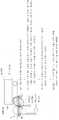
도 1은 본 발명의 실시형태에 관한 차량의 차량 저부를 전자기 유도 센서로 검지하는 예를 설명하는 도이다.
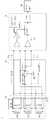
도 2는 본 발명의 실시형태에 관한 차량 검지 시험에 사용한 검지 시스템의 구성예를 나타낸 도이다.
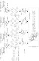
도 3은 본 발명의 실시형태에 관한 센서부(송신 코일, 제1 수신 코일, 제2 수신 코일)를 통과하는 경우에 데이터 로거(data logger)로 얻어진 데이터의 궤적에 대하여 설명하는 도이다.
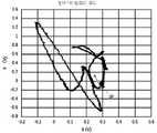
도 4는 본 발명의 실시형태에 관한 원박스카의 X, Y 궤적을 나타낸 도이다.
도 5는 본 발명의 실시형태에 관한 원박스카에 대하여 수집한 시계열 X, Y 데이터를 수신 레벨과 위상값으로 변환하여 시계열로 한 데이터를 나타낸 도이다.
도 6은 본 발명의 실시형태에 관한 원박스카의 X, Y 궤적을 나타낸 도이다.
도 7은 본 발명의 실시형태에 관한 원박스카에 대하여 수집한 시계열 X, Y 데이터를 수신 레벨과 위상값으로 변환하여 시계열로 한 데이터를 나타낸 도이다.
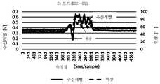
도 8은 본 발명의 실시형태에 관한 2t트럭의 X, Y 궤적을 나타낸 도이다.
도 9는 본 발명에 관한 2t트럭에 대하여 수집한 시계열 X, Y 데이터를 수신 레벨과 위상값으로 변환하여 시계열로 한 데이터를 나타낸 도이다.
도 10은 본 발명의 실시형태에 관한 2t트럭의 X, Y 궤적을 나타낸 도이다.
도 11은 본 발명에 관한 2t트럭에 대하여 수집한 시계열 X, Y 데이터를 수신 레벨과 위상값으로 변환하여 시계열로 한 데이터를 나타낸 도이다.
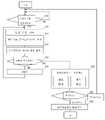
도 12는 본 발명의 실시형태에 관한 궤적 판정 수법의 일례를 나타낸 플로 차트이다.
도 13은 본 발명의 실시형태에 관한 감시 대상 지역(공사 현장 등의 시큐리티 감시)에 적용한 감시 시스템을 나타내는 도이다.
도 14는 본 발명의 실시형태에 관한 감시 시스템의 개략 블록도이다.BRIEF DESCRIPTION OF THE DRAWINGS It is a figure explaining the example which detects the vehicle bottom of the vehicle which concerns on embodiment of this invention with an electromagnetic induction sensor.
2 is a diagram showing a configuration example of a detection system used for a vehicle detection test according to an embodiment of the present invention.
3 is a diagram for explaining the trajectory of data obtained by a data logger when passing through a sensor unit (transmitting coil, first receiving coil, and second receiving coil) according to the embodiment of the present invention.
4 is a view showing the X and Y trajectories of the one box car according to the embodiment of the present invention.
5 is a diagram illustrating time-series data obtained by converting time-series X and Y data collected with respect to one boxcar according to an embodiment of the present invention into reception level and phase values.
6 is a view showing the X, Y trajectories of the one box car according to the embodiment of the present invention.
7 is a diagram illustrating time-series data obtained by converting time-series X and Y data collected with respect to one boxcar according to an embodiment of the present invention into reception levels and phase values.
8 is a diagram showing X and Y trajectories of a 2t truck according to an embodiment of the present invention.
9 is a diagram illustrating time series data obtained by converting time series X and Y data collected for a 2t truck according to the present invention into reception level and phase values.
Fig. 10 is a diagram showing the X and Y trajectories of the 2t truck according to the embodiment of the present invention.
11 is a diagram illustrating time series data obtained by converting time series X and Y data collected for a 2t truck according to the present invention into reception level and phase values.
12 is a flowchart showing an example of a locus determination method according to an embodiment of the present invention.
It is a figure which shows the monitoring system applied to the monitoring target area (security monitoring of a construction site etc.) which concerns on embodiment of this invention.
14 is a schematic block diagram of a monitoring system according to an embodiment of the present invention.
이어서 본 발명을 실시하기 위한 형태(이하, 단순히 ‘실시형태’라고 함)를 도면을 참조하여 구체적으로 설명한다. 본 실시형태의 개요는 다음과 같다. 즉,Next, a form for carrying out the present invention (hereinafter simply referred to as an 'embodiment') will be described in detail with reference to the drawings. The outline of this embodiment is as follows. in other words,
(1)특정 차량의 추출 수단(1) Extraction means of a specific vehicle
전자기 유도 센서를 차량 검지 범위 내에 설치한다. 전자기 유도 센서가 차량을 검지했을 때의 검지 파형을 직교 좌표계로 나타낸 궤도 화상을 취득한다. 취득한 검지 파형의 궤적 화상과 사전에 데이터 등록되어 있는 차 종류마다 검지 파형의 궤적 화상(즉, 참조 화상)과 비교조회(照合) 한다. 비교 조회는 화상 매칭의 정도로 판정한다. 이것에 의해 차량 판별뿐만 아니라 차 종류 판별(특정 차량의 추출)도 실시한다.Install the electromagnetic induction sensor within the vehicle detection range. A trajectory image is acquired in which the detection waveform when the electromagnetic induction sensor detects a vehicle is expressed in a Cartesian coordinate system. The acquired locus image of the detection waveform is compared and queried with the locus image of the detection waveform (that is, a reference image) for each type of vehicle registered in advance as data. The comparative inquiry determines the degree of image matching. In this way, not only vehicle identification but also vehicle type identification (extraction of a specific vehicle) is performed.
(2) 특정 차량의 진행 방향 판정 수단(2) Means for determining the traveling direction of a specific vehicle
전자기 유도 센서가 차량을 검지했을 때의 궤적 화상의 궤적 방향을 판정함으로써 차량 진행 방향을 판정한다. 궤적 방향 판정은 궤적을 화상화 할 시에 궤적 개시점부터 종료에 이르는 사이를, 계조 또는 콘트라스트 차이를 설치한다. 계조 또는 콘트라스트 차이를 설치한 화상 데이터를 화상 처리하여 궤적 개시부터 종료까지의 궤적 방향을 판정한다.The vehicle traveling direction is determined by determining the trajectory direction of the trajectory image when the electromagnetic induction sensor detects the vehicle. The trajectory direction determination establishes a gradation or contrast difference between the trajectory starting point and the ending point when the trajectory is imaged. The trajectory direction from the trajectory start to the end is determined by image processing the image data to which the gradation or contrast difference is provided.
<기본 기술><Basic Skills>
먼저 전자기 유도 센서를 이용한 차량 종류 판별의 기본 기술에 대하여 설명한다. 전자기 유도 센서는 금속 재료에 생기는 와전류 작용을 이용하고, 금속 재료에 특화된 거리 계측 용도나 금속 종류 판정 용도에 적용할 수 있다. 차량 종류 판별은 금속으로 구성된 차량마다 생기는 형상 차이에 의한 거리 차이 정보, 차량마다 구성되는 금속 차이의 정보를 전자기 유도 센서로 취득하여 실시하는 구조이다.First, the basic technology of vehicle type discrimination using the electromagnetic induction sensor will be described. The electromagnetic induction sensor utilizes the action of an eddy current generated in a metal material, and can be applied to a distance measurement application specialized for a metal material or a metal type determination application. Vehicle type discrimination is a structure in which distance difference information due to shape differences occurring for each vehicle made of metal and information on metal difference configured for each vehicle are acquired by an electromagnetic induction sensor and performed.
이하, 최적 실시 방법을 도 1로 설명한다. 도 1에서는 차량(90)의 차량 저부(92)를 전자기 유도 센서로 검지하는 예를 나타낸다. 전자기 유도 센서인 센서부(10)는 송신 코일(TX1), 제1 수신 코일(RX1), 제2 수신 코일(RX2)을 구비한다.Hereinafter, an optimal implementation method will be described with reference to FIG. 1 . 1 shows an example in which the vehicle bottom 92 of the
송신 코일(TX1)과 제1 수신 코일(RX1)의 코일 간 거리(L1) 및 송신 코일(TX1)과 제2 수신 코일(RX2)의 코일 간 거리(L2)는 같은 거리로 설치한다. 센서부(10)는 이와 같은 구성으로 도로에 매설된다. 이 상태에서 송신 코일(TX1)에 주파수(f0)의 송신 전류(I)를 공급하면 송신 코일(TX1)로부터 교번 자계가 방출된다. 같은 거리로 놓은 제1 수신 코일(RX1)과 제2 수신 코일(RX2)에 유기하는 전압은 각각 동일 레벨이고, 도 1에 출력되는 차동 출력값(차동 출력 신호)은 거의 0V 상태이다. 이 상태가 차량을 검지하지 않은 정상 상태(차량 비검지 상태)이다.The distance L1 between the coils of the transmitting coil TX1 and the first receiving coil RX1 and the distance L2 between the coils of the transmitting coil TX1 and the second receiving coil RX2 are installed at the same distance. The
차량 비검지 상태로부터 차량(90)이 센서부(10)의 바로 위를 통과하면 도 1에 나타내는 메커니즘에 의해 차량(90)마다 상이한 검지 파형이 차동 출력 신호로서 출력된다. 구체적으로는 강재인 차량(90)의 자계에 의해 송신 코일(TX1)의 방출 자계가 끌어 당겨진다(S1).When the
차량(90)이 가까워지면 도 중 파선으로 나타내는 상태 1부터 일점쇄선으로 나타내는 상태 2로 변화한다(S2). 상태 2의 자계가 됨으로써 수신 코일(여기서는 제1 수신 코일(RX1))을 관통하는 자계가 코일과 교착한다. 또한 와전류의 반자계 작용도 동반하며 제1 수신 코일(RX1)을 관통하는 자계는 감소한다. 또한 와전류의 작용은 위상 변화도 동반한다.When the
제1 수신 코일(RX1)의 상태 1의 자계 때(차량 비검지 때)의 유기(誘起) 전압에 대하여 유기 전압 저하와 위상 변화가 발생한다(S3).An induced voltage drop and a phase change occur with respect to the induced voltage at the time of the magnetic field in the
이어서 제2 수신 코일(RX2)과 제1 수신 코일(RX1)의 차동 출력 신호가 차량 진행에 맞추어 차량 저부(92)의 요철(凹凸)이나 금속 종류 별에 맞춰 변화한다(S4). 이와 같이 차량마다 상이한 검지 파형이 얻어짐으로써 차량 판별뿐만 아니라 차종 판별이 가능해진다.Then, the differential output signal of the second receiving coil RX2 and the first receiving coil RX1 is changed according to the unevenness of the vehicle bottom 92 or the type of metal according to the progress of the vehicle (S4). In this way, different detection waveforms are obtained for each vehicle, so that not only vehicle identification but also vehicle type identification is possible.
이하, 제1 수신 코일(RX1) 및 제2수신 코일(RX2)을 차동 접속하고 있는 장점을 나타낸다. 본 방식은 차동 접속하고 있기 때문에 온도 변화에 의한 코일의 인덕턴스 변화는 제1 수신 코일(RX1)과 제2 수신 코일(RX2)로 동일하고, 차동 접속하고 있음으로써 지워진다. 또한 송신 코일(TX1)의 인덕턴스 변화에 의해 방출 자계 레벨이 변화했다고 해도 차동 접속하고 있기 때문에 제1 수신 코일(RX1)의 유기 전압과 제2 수신 코일(RX2)의 유기 전압 모두 감소하고, 차동 출력 결과에 변화는 없다. 즉, 외부 환경의 온도 변화가 발생했다고 해도 정상 때의 검지 출력은 변하지 않고 안정값이다. 따라서 제1 수신 코일(RX1)과 제2 수신 코일(RX2)을 차동 접속함으로써 차량 저부(92)의 요철 상태만을 감도 좋게 검지 가능하다. 또한 철도 연선이나 건널목 주위 등 전자기 노이즈 환경 하에 있어서도 제1 수신 코일(RX1)과 제2 수신 코일(RX2) 간을 차동 접속으로 하고 있으므로 이른바 공통 모드 노이즈가 되어 출력 파형에 영향을 받지 않는다. 즉, 본 방식을 채용함으로써 전자기 노이즈원을 회피하기 위한 필터나 주파수(f0)를 바꾸는 일 없이 운용할 수 있다.Hereinafter, an advantage of differentially connecting the first receiving coil RX1 and the second receiving coil RX2 will be described. Since this method is differentially connected, the change in inductance of the coil due to temperature change is the same for the first receiving coil RX1 and the second receiving coil RX2, and is eliminated by differential connection. In addition, even if the emission magnetic field level changes due to a change in the inductance of the transmitting coil TX1, since the differential connection is made, both the induced voltage of the first receiving coil RX1 and the induced voltage of the second receiving coil RX2 decrease, and the differential output There is no change in the result. That is, even if the temperature change of the external environment occurs, the detection output at the normal time does not change and is a stable value. Therefore, only the uneven state of the vehicle bottom 92 can be detected with high sensitivity by differentially connecting the first receiving coil RX1 and the second receiving coil RX2. In addition, even under an electromagnetic noise environment such as a railway stranded line or around a crossing, since the first receiving coil RX1 and the second receiving coil RX2 are differentially connected, so-called common mode noise is not affected by the output waveform. That is, by adopting this method, it is possible to operate without changing the filter or the frequency f0 for avoiding the electromagnetic noise source.
이하, 구체적인 차량 검지예(차량 종류 판별 예시)의 시험 결과를 설명한다. 도 2는 시험에 사용한 검지 시스템 1의 구성예를 나타낸다. 여기서 사용한 검지 시스템 1은 상술한 센서부(10)와, 송수신 앰프부(20)와, 신호 처리부(30)와, 데이터 로거(40)로 구성되어 있다. 신호 처리부(30)는 이른바 락인(locked-in) 앰프이다.Hereinafter, test results of a specific vehicle detection example (vehicle type discrimination example) will be described. 2 : shows the structural example of the
송수신 앰프부(20)에서는 센서부(10)의 송신 코일(TX1)에 파워 앰프로부터 주파수(f0)의 교류 전류가 인가된다. 이것에 의해 교번 자계가 출력된다. 주파수(f0)의 송신 신호와 제1 수신 코일(RX1)과 제2 수신 코일(RX2)의 차동 출력 결과가 락인 앰프인 신호 처리부(30)에 입력된다. 신호 처리부(30)는 연산 처리 결과의 극좌표계의 X좌표와 Y좌표를 데이터 로거(40)에 출력한다. 데이터 로거(40)는 신호 처리부(30)로부터의 출력 결과를 5 ms마다 수집한다.In the transmission/
도 3을 참조하여 제1 수신 코일(RX1)→제2 수신 코일(RX2) 방향으로 차량을 통과시켰을 경우 제2 수신 코일(RX2)→제1 수신 코일(RX1) 방향으로 차량을 통과시켰을 경우에 데이터 로거(40)에서 획득하는 데이터의 궤적에 대하여 설명한다. 노면에 매설된 센서부(10)는 도에서는 좌측에 제1 수신 코일(RX1), 우측에 제2 수신 코일(RX2), 중앙에 송신 코일(TX1)가 배치되어 있다.Referring to Figure 3, when the vehicle passes in the direction of the first receiving coil (RX1) → the second receiving coil (RX2) When the vehicle passes in the direction of the second receiving coil (RX2) → the first receiving coil (RX1) The trajectory of data acquired by the
상태 1은 센서부(10)의 좌측에 차량(90)이 있는 차량 비검지 상태A이다. 상태 2는 차량(90)의 우측 차륜이 제1 수신 코일(RX1)과 송신 코일(TX1) 간에 있는 차량 검지 상태A이다.
상태 3은 차량(90)의 좌측 차륜이 제2 수신 코일(RX2)과 송신 코일(TX1) 간에 있는 차량 검지 상태B이다. 상태 4는 센서부(10)의 우측에 차량(90)이 있는 차량 비검지 상태B이다.
상태 1에서 수신 신호는 레벨 R0이고 송신 신호에 대하여 위상 θ1만큼 어긋나 있고, X, Y좌표계에서는 좌표<1>(X0, Y0)에 플롯된다.In
상태 2에서는 수신 신호는 레벨 R1이고 송신 신호에 대하여 위상 θ2만큼 어긋나 있고, X, Y좌표계에서는 좌표<2>(X1, Y1)에 플롯된다. 차량(90)이 상태 1에서 상태 2로 천이(遷移)함에 따라 플롯된 점은 좌표<1>에서 <2>를 향하여 도시한 바와 같이 원호(A1)를 그린다.In
상태 3에서 수신 신호는 레벨 R2고 송신 신호에 대하여 위상 θ3만큼 어긋나 있고(여기에서는 위상차0), X, Y좌표계에서는 좌표<3>(X1, Y1)에 플롯된다. 차량(90)이 상태 2에서 상태 3으로 천이함에 따라 플롯된 점은 좌표<2>에서 <3>을 향하여 도시한 바와 같이 원호(A2)를 그린다.In
상태 4에서는 상태 1과 동일 상태로 돌아가고, 수신 신호는 레벨 R0이고, 송신 신호에 대하여 위상 θ1만큼 어긋나 있고, X, Y좌표계에서는 좌표<4>(X0, Y0)에 플롯된다. 차량(90)이 상태 3에서 상태 4로 천이함에 따라 플롯된 점은 좌표<3>에서 <4>를 향하여 도시한 바와 같이 원호(A3)를 그린다.In state 4, it returns to the same state as in
RX1→RX2 방향으로 차량(90)을 통과시켰을 경우와 RX2→RX1 방향으로 차량(90)을 통과시켰을 경우에는 플롯의 궤적(상기 예에서는 원호 A, B, C)은 반대 방향으로 그려진다. 즉, 제1 수신 코일(RX1) →제2 수신 코일(RX2) 방향으로 차량(90)이 통과하는 경우 좌표<1>→<2>→<3>→<4>의 순서(원호 A1→A2→A3 순서)로 궤적이 그려진다. 또한 제2 수신 코일(RX2) →제1 수신 코일(RX1)의 방향으로 차량(90)이 통과하는 경우 좌표<4>→<3>→<2>→<1>의 순서(원호 A3→A2→A1 순서)로 궤적이 그려진다.When the
이어서 도 4 ~ 도 11에 검지 시스템(1)의 구성인 RX1→RX2 방향으로 차량(90)을 통과시킨 경우와 RX2→RX1 방향으로 차량(90)을 통과시킨 경우에 대하여 2차종 데이터 결과를 나타낸다.Next, in FIGS. 4 to 11 , the second car model data results are shown for the case where the
도 4 ~ 도 7이 원박스카 데이터이고, 도 8 ~ 도 11이 2t 트럭 데이터이다. 도 4, 도 6이 원박스카의 X, Y 궤적이다. 도 5, 도 7이 수집한 시계열 X, Y 데이터를 수신 레벨과 위상값으로 변환하여 시계열로 한 데이터이다. 도 8, 도 10이 2t 트럭의 X, Y 궤적, 도 9, 도 11이 수집한 X, Y 데이터를 수신 레벨과 위상값으로 변환하여 시계열로 한 데이터이다.4 to 7 are one box car data, and FIGS. 8 to 11 are 2t truck data. 4 and 6 are X and Y trajectories of the one box car. 5 and 7 are data obtained by converting the time series X and Y data collected into reception level and phase values into a time series. 8 and 10 are the X and Y trajectories of the 2t truck, and the X and Y data collected in FIGS. 9 and 11 are converted into reception level and phase values to be time-series data.
본 시험에서 아래와 같은 특정 차량 추출 수법(차량 종류 추출 수법)의 유효성을 확인 가능하다. 구체적으로는 차량(90)에 의해 궤적 형상이 상이하다. 이 특징에 의해 차량 종류 추출 수법으로서는 차량(90)마다 궤적 형상을 비교함으로써 차량(90)을 특정 가능하다. 궤적 형상의 비교 방법으로서는 사전 데이터 등록되어 있는 차량마다 궤적 화상(참조 화상)과 획득한 궤적 형상 데이터(즉, 궤적 화상)를 화상 처리에서 일반적으로 사용되고 있는 템플릿 매칭(Template Matching)에 의해 형상 비교를 실시하고 일치 비율로 비교 판정할 수 있다.In this test, it is possible to check the validity of the following specific vehicle extraction method (vehicle type extraction method). Specifically, the trajectory shape is different depending on the
도 4와 도 6의 원박스카의 제1 수신 코일(RX1)→제2 수신 코일(RX2)의 방향, 제2 수신 코일(RX2) →제1수신코일(RX1)의 방향으로 차량(90)이 진행한 궤적을 참조한다. 이들 도에서 ‘●’의 시점(始点) 마크가 검지 개시 때의 궤적 시점(SP)이다.The
도에 나타낸 바와 같이 제1 수신 코일(RX1) →제2 수신 코일(RX2)의 방향과 제2 수신 코일(RX1) →제1 수신 코일(RX2)의 방향에 의해 궤적 개시 때로부터 변화 개시 방향이 상이한 결과가 된다. 즉, 궤적 방향을 판정함으로써 차량 진행 방향을 판정 가능하다. 도 8과 도 10은 2t 트럭의 예이고, 2t 트럭에 있어서도 동일한 결과였다.As shown in the figure, the direction of change start from the trajectory start is changed by the direction of the first receiving coil RX1 → the second receiving coil RX2 and the direction of the second receiving coil RX1 → the first receiving coil RX2. different results. That is, the vehicle traveling direction can be determined by determining the trajectory direction. 8 and 10 are examples of the 2t truck, and the same results were obtained for the 2t truck.
이하, 궤적 판정 수법의 일례를 도 12의 플로 차트에 나타낸다. 궤적 판정은 취득한 데이터를 화상 변환하고 화상 처리를 하여 판정한다.Hereinafter, an example of a locus determination method is shown in the flowchart of FIG. Trajectory determination is made by image-converting the acquired data and performing image processing.
차량(90)을 검지하지 않은 정상 상태 때, (X, Y)값은 일정 범위 내 데이터에 들어가 있다(S10의 No). 차량(90)이 센서를 통과하는 경우에 일정 레벨 범위를 초과한 차량 검지 레벨의 (Xi, Yi)값이 된다(S10의 Yes). 즉, 시스템(도 2의 검지 시스템(1)이나 후술하는 도 14의 감시 시스템(101)에 상당하는 장치)은 일정 레벨 범위를 초과했을 때부터 궤적 데이터를 취득하여 궤적 판정을 실시한다(S12 ~ S26).In the steady state in which the
궤적 판정의 기본적인 사고 방식은 다음과 같다. 궤적 판정을 실시하기 위한 데이터 샘플링은 차량 속도에 대하여 충분히 빠른 샘플링이며 또한 궤적 형상 판정이 가능한 샘플링 분해능이 요구된다. 따라서 궤적 판정 처리에 있어서 일정 이상의 고속 샘플링이 요구된다. 이때, 궤적 판정을 위해 취득하는 데이터의 수량은 차량 속도가 느린 경우나 센서상에서 일단 정지한 경우에 데이터 취득 수량이 막대해진다. 이 데이터 수량의 문제와 더불어 궤적 형상은 차량 종류마다 상이하기 때문에 복잡한 알고리즘으로 궤적의 법칙성을 찾아내어 연산시키는 데는 처리 부하적으로 무리가 있다. 이 점에서 화상 변환을 하면 차량 속도 차이는 화상 데이터상에서는 궤적 플롯 수량의 소밀(粗密) 차이로 변할 뿐이며, 판정 처리 부하에 영향은 없다. 즉, 취득한 데이터를 일단 화상 변환하고 화상 처리를 하여 사전 등록되어 있는 기준이 되는 차종의 궤적과 패턴 매칭을 시켜서 특정 차종을 판단하는 것이 처리 부하도 적고 경제적으로 유효하다.The basic way of thinking about trajectory judgment is as follows. Data sampling for performing the trajectory determination is sampling that is sufficiently fast with respect to the vehicle speed, and a sampling resolution capable of determining the trajectory shape is required. Therefore, in the locus determination process, high-speed sampling of a certain level or higher is required. At this time, the amount of data acquired for trajectory determination becomes large when the vehicle speed is slow or when the sensor is temporarily stopped. In addition to the problem of the amount of data, since the shape of the trajectory is different for each type of vehicle, it is difficult in terms of processing load to find and calculate the law of the trajectory with a complex algorithm. In this regard, when image conversion is performed, the vehicle speed difference only changes to a difference in the trajectory plot quantity on the image data, and does not affect the judgment processing load. That is, it is economically effective to perform image conversion of the acquired data and image processing to determine a specific vehicle model by pattern matching with the trajectory of a pre-registered standard vehicle model.
또한 방향 판별에 관해서는 궤적 데이터 취득 개시부터 데이터 취득 종료까지의 사이에서 데이터 출력시에 계조 또는 콘트라스트 차이를 내어 출력시킨다. 그 결과 궤적 화상에는 계조 또는 콘트라스트 차이가 삽입된 궤적 화상이 된다. 이 계조 또는 콘트라스트 차이를 화상 처리로 판정하고, 궤적의 방향을 판정한다.In regard to direction determination, a difference in gradation or contrast is outputted at the time of data output from the start of acquisition of the locus data to the end of acquisition of the data. As a result, the locus image becomes a locus image in which a gradation or contrast difference is inserted. This gradation or contrast difference is determined by image processing, and the direction of the locus is determined.
구체적인 플로로서 궤적 판정에서는 시스템은 (Xi, Yi)를 취득하고(S12), 상술한 방향 판별의 관점에서 계조 또는 콘트라스트 데이터를 부여하고(S14), X, Y축에 데이터 플롯 출력을 한다(S16). 여기서 충분한 궤적이 그려지지 않으면(S18의 No) 즉, i=i+1에 인크리멘트 하고(S20), (Xi, Yi)의 취득으로 돌아간다(S12).As a specific flow, in the trajectory determination, the system acquires (Xi, Yi) (S12), provides gradation or contrast data from the viewpoint of the above-described direction determination (S14), and outputs data plots on the X and Y axes (S16). ). If a sufficient trajectory is not drawn here (No in S18), that is, it increments to i=i+1 (S20), and returns to the acquisition of (Xi, Yi) (S12).
충분한 궤적이 그려지면(S18의 Yes) 시스템은 데이터 베이스 조회 처리를 실시한다(S22). 즉, 궤적 화상과 참조 화상의 매칭을 실시하고 특정 차종인지 여부를 판정한다(S24).When sufficient trajectories are drawn (Yes in S18), the system performs a database inquiry process (S22). That is, the trajectory image and the reference image are matched, and it is determined whether or not it is a specific vehicle model (S24).
특정 차종이면(S24의 Yes) 시스템은 그 특정 차종을 추출하고 나아가 방향을 출력한다(S26). 특정 차종이 아닌 경우(S24의 No) 즉, 노이즈로 판단되는 경우에는 S10의 처리로 돌아간다.If it is a specific vehicle type (Yes in S24), the system extracts the specific vehicle type and further outputs a direction (S26). When it is not a specific vehicle model (No in S24), that is, when it is determined as noise, the process returns to S10.
도 13은 상술한 기술을 감시 대상 지역(99)(공사 현장 등의 보안 감시)에 적용한 감시 시스템(101)의 개요이다. 도 14는 감시 시스템(101)의 개략 블록도이다.13 is an outline of a monitoring system 101 in which the above-described technology is applied to a monitoring target area 99 (security monitoring of a construction site, etc.). 14 is a schematic block diagram of the monitoring system 101 .
도 13에 나타낸 바와 같이 공사 현장인 감시 대상 지역(99)에는 복수의 입퇴장 게이트, 여기서는 4개의 입퇴장 게이트(1)~(4)가 설치되어 있다. 종래에는 이와 같은 작업 지역에서는 작업 책임자와 작업원의 인원 파악을 ID 카드 등으로 실시하고, 차량(90)에 관해서는 주차 허가서를 받아 작업 장소에 주차한다. 작업 종료 후의 퇴장 때 작업원은 재차 ID 카드 조회를 실시하고 차량(90)은 주차 허가서를 반환한다고 하는 체크를 실시하고 있다. 이와 같은 시스템에서는 작업원은 ID 카드 등으로 입장 시간 및 퇴장 시간을 체크 가능하기 때문에 보안 레벨로서는 일정 레벨을 확보 가능한데, 차량(90)은 감시 대상 지역(99) 내에 방치한 상태로 하는 것도 의도적으로 용이하다. 이와 같은 상황은 보안 확보의 관점에서 바람직하지 않다.As shown in Fig. 13, a plurality of entrance and exit gates, four entrance and
그래서 감시 대상 지역(99)에는 전자기 유도 센서를 사용한 감시 시스템(101)이 구축된다. 감시 시스템(101)은 입퇴장 게이트(1)~(4)의 각각에 설치된 4개의 센서부(1)~(4)(10_1~10_4)와, 4개의 송수신 앰프부(1)~(4)(20_1~20_4)와, 관리부(200)를 구비한다. 센서부(1)~(4)(10_1~10_4)와 송수신 앰프부(1)~(4)(20_1~20_4)는 도 2의 센서부(10) 및 송수신 앰프부(20)와 동일한 구성의 장치이다.Therefore, the monitoring system 101 using the electromagnetic induction sensor is built in the
관리부(200)는 신호 처리부(30)와 판정부(140)와 등록 차량 DB(데이터 베이스)(150)를 구비한다.The
신호 처리부(30)는 4개의 송수신 앰프부(1)~(4)(20_1~20_4)를 접속하고, 센서부(1)~(4)(10_1~10_4)의 송수신 신호를 취득하고, 각각에 대하여 연산 처리 결과의 극좌표계의 X좌표와 Y좌표를 판정부(140)에 출력한다.The
등록 차량DB(150)에는 작업 지역에의 입장 허가 차량의 차량 궤적 데이터인 참조 화상이 사전에 등록되어 있다. 참조 화상은 도에 나타내지 않으나 초회에 입장하는 차량(90)이 감시 대상 지역(99)에 들어가기 위한 전용 입장구를 설치하고 차량 궤적 데이터와 입장 방향의 궤적 방향을 취득하여 입장 허가의 차량 궤적 데이터 즉, 참조 화상으로 하면 된다.In the registered
판정부(140)는 센서부(10)(센서부(1)~(4)10_1~10_4) 위를 차량(90)이 통과하면 취득한 궤적 화상과 참조 화상 사이에서 패턴 매칭 처리를 실행하여 등록 차량의 참조 화상과 일치하는지를 판정한다.The
참조 화상에 매칭한 경우 판정부(140)는 입장 방향인지 퇴장 방향인지 궤적 방향의 판정을 실시한다. 궤적 판정 결과, 입장 방향인 경우 시스템은 등록 차량DB(150)에 등록되어 있는 허가 대상의 참조 화상에 입장 플래그를 세운다. 퇴장 방향인 경우 판정부(140)는 취득한 궤적 화상과 데이터 베이스상의 입장 플래그 체크에 들어 있는 참조 화상 간에 조회하고, 퇴장한 대상 데이터의 입장 플래그를 삭제한다. 이와 같이 하면 임의의 시간 단위에서 차량의 체크인과 체크아웃의 감시가 가능하다. 그 결과 차량(90)이 방치되어 있는 것을 방지 가능하고 보안성을 확보할 수 있다.In the case of matching with the reference image, the
이상, 본 발명의 실시형태의 특징을 간단히 정리하면 다음과 같다. 즉, (1) 전자기 유도 센서로 차량 계측한 궤도 화상의 결과로부터 차량 종류 판별을 판정한다. (2) 또한 전자기 유도 센서(센서부(10))는 송신 자계 방출용의 송신 코일(TX1)과, 그것으로부터 방출된 자계를 수신하는 제1 수신 코일(RX1), 제2 수신 코일(RX2)을 사용한다. 제1 수신 코일(RX1)과 제2 수신 코일(RX2)은 차동 접속을 특징으로 한 센서이다. (3) 제1 수신 코일(RX1), 제2 수신 코일(RX2)을 차동 접속함으로써 온도 변화에 의한 인덕턴스 변화나 전자기 환경 하에 있어서의 전자기 노이즈를 캔슬 가능하다. 따라서 차량 검지 때의 수신 레벨 및 위상차를 안정적으로 출력 가능하다. (4) 차량(90)마다 수신 레벨과 위상차를 직교 좌표상에 플롯하고, 획득한 궤적 화상의 형상 변화로부터 차종 판별을 실시한다. (5) 궤적 화상의 형상 조회는 사전에 등록되어 있는 참조 화상과 조회함으로써 차종 판별을 실시한다.As mentioned above, the characteristics of embodiment of this invention are summarized briefly as follows. That is, (1) the vehicle type discrimination is determined from the result of the track image measured by the vehicle by the electromagnetic induction sensor. (2) Further, the electromagnetic induction sensor (sensor unit 10) includes a transmitting coil TX1 for emitting a transmitting magnetic field, and a first receiving coil RX1 and a second receiving coil RX2 for receiving the magnetic field emitted therefrom. use The first receiving coil RX1 and the second receiving coil RX2 are sensors characterized by differential connection. (3) By differentially connecting the first receiving coil RX1 and the second receiving coil RX2, it is possible to cancel an inductance change due to a temperature change or an electromagnetic noise in an electromagnetic environment. Therefore, it is possible to stably output the reception level and phase difference at the time of vehicle detection. (4) For each
이상, 본 발명의 실시형태에 의거하여 설명하였다. 이 실시형태는 예시로서 그들 각 구성 요소나 처리 프로세스의 조합에 다양한 변형예가 가능하다는 것, 또한 그러한 변형예도 본 발명의 범위에 있다는 것은 당업자에게 이해되는 부분이다.As mentioned above, it demonstrated based on embodiment of this invention. This embodiment is an example, and it is a part for those skilled in the art to understand that various modifications are possible in combination of their respective components or processing processes, and that such modifications are also within the scope of the present invention.
도 13에서는 공사 현장에서 적용한 예를 나타내었는데 다른 적용예로서 일반 주행로 내에 설치하여 버스를 추출하는 시스템이나 주차장 입구 등에 설치하여 수송업자의 차량만을 추출하는 시스템 등, 다양한 시스템에 적용할 수 있다.13 shows an example applied at the construction site, and as another application example, it can be applied to various systems, such as a system for extracting a bus by installing it in a general running path or a system for extracting only a transporter's vehicle by installing it at the entrance of a parking lot.
또한 차동 접속 방법에서 송신 코일(TX1)-제1 수신 코일(RX1) 간의 거리(L1), 송신 코일(TX1)-제2 수신 코일(TX2) 간의 거리(L2)를 일정하게 한 예를 나타내었는데, 특히 L1과 L2 간의 거리를 일정하게 하지 않고 L1과 L2와 이간 차이를 설정한다고 해도 출력 파형 궤도가 상이할 뿐이며, 동일하게 차량 검출을 실시할 수 있다. 또한 차량(90)의 차량 저부(92)를 검지하는 방법으로 설명을 하였는데, 차량 머리부, 차량 가로부여도 된다. 또한 차량(90)에 관해서도 철도 차량, 도로 교통 차량, 오토바이 등 금속 차체로 되어 있으면 된다. 나아가 검지 대상으로서 차량(90)에 한정하지 않고 선박이나 항공 등과 같이 금속을 가지는 탈것에 대해서도 적용할 수 있다.In addition, in the differential connection method, an example in which the distance (L1) between the transmitting coil (TX1) - the first receiving coil (RX1) and the distance (L2) between the transmitting coil (TX1) and the second receiving coil (TX2) are constant is shown. , in particular, even if the distance between L1 and L2 is not constant and the difference between L1 and L2 is set, only the output waveform trajectories are different, and vehicle detection can be performed in the same manner. In addition, although the method of detecting the vehicle bottom 92 of the
또한 궤적으로서 검지 개시 때의 궤적 시점(SP)으로부터 그려지고, 궤적 시점(SP)에 돌아갈 때까지의 궤적을 전부 플롯하여 조회하는 예를 나타내었는데, 궤적 시점(SP)으로부터 가까운 부분만으로 판별해도 된다. 즉, 등록한 궤적이 다른 차량(90)과 판별이 가능한 특징을, 궤적 시점(SP)으로부터 가까운 부분에 가지고 있으면 그 부분만으로 판별함으로써 등록 데이터량의 억제 및 판별 처리 부하의 저감(판별 속도 향상)이 실현 가능하다.In addition, as a trajectory, an example is shown in which all trajectories drawn from the trajectory start point SP at the start of detection and returned to the trajectory start point SP are plotted and queried. . In other words, if the registered trajectory has a characteristic that can be discriminated from the
또한 화상 처리를 실시하지 않고 획득한 데이터의 특징을 추출하고 차량 검출이나 차종 판별을 실시하는 것도 가능하다. 예를 들어, 일정 역치를 초과한 후에 XY좌표계(직교 좌표계)로 출력하여 X출력의 MIN값과 MAX값을 추출하고 Y좌표에 관해서도 동일하게 MIN값과 MAX값을 추출하여 X좌표의 변동 범위값과 Y좌표의 변동 범위값으로부터 차종 판정을 실시해도 된다. 또한 획득한 데이터의 상관계수(특히 자기 상관계수)를 구함으로써 차종 판별을 실시해도 된다.It is also possible to extract the characteristics of the acquired data without performing image processing to perform vehicle detection or vehicle type discrimination. For example, after exceeding a certain threshold, output to XY coordinate system (Cartesian coordinate system) to extract MIN and MAX values of X output and the value of the variation range of the Y-coordinate may be used to determine the vehicle model. In addition, vehicle model discrimination may be performed by obtaining a correlation coefficient (especially an autocorrelation coefficient) of the acquired data.
1 검지 시스템
10 센서부
10_1~10_4 센서부(1)~(4)
20 송수신 앰프부
20_1~20_4 송수신 앰프부(1)~(4)
30 신호 처리부
40 데이터 로거
90 차량
92 차량 저부
99 감시 대상 지역
140 판정부
150 등록 차량DB
101 감시 시스템
RX1 제1 수신 코일
RX2 제2 수신 코일
TX1 송신 코일1 detection system
10 sensor unit
10_1~10_4 Sensor part (1)~(4)
20 Transceiver Amplifier
20_1~20_4 Transceiver Amplifier (1)~(4)
30 signal processing unit
40 data logger
90 vehicles
92 car bottom
99 Surveillance Area
140 Tribunal
150 registered vehicle DB
101 Surveillance System
RX1 first receiving coil
RX2 2nd receiving coil
TX1 transmit coil
Claims (4)
Translated fromKorean탈것의 진행 방향을 따라 상기 송신 코일과 사이를 떨어뜨린 위치에 설치되어 상기 송신 코일과 자기적으로 결합 가능한 제1 수신 코일과,
상기 진행 방향을 따라 상기 송신 코일로부터 보아 상기 제1 수신 코일과 대칭의 위치에 설치되어 상기 제1 수신 코일과 차동 접속된 제2 수신 코일을 구비하는 전자기 유도 센서와,
상기 제1 수신 코일과 상기 제2 수신 코일의 검지 파형을 수신 레벨과 위상차로 나타내는 좌표계에 시계열로 플롯하여 궤적 화상으로서 출력하는 궤적 화상 출력부와,
상기 궤적 화상에 의거하여 상기 전자기 유도 센서가 설치되어 있는 영역을 탈것이 통과한 것을 검지하는 탈것 검지부
를 구비하는 것을 특징으로 하는 검지 시스템.a transmitting coil;
A first receiving coil which is installed at a distance between the transmitting coil and the transmitting coil along the traveling direction of the vehicle and magnetically coupled to the transmitting coil;
An electromagnetic induction sensor having a second receiving coil differentially connected to the first receiving coil and installed at a position symmetrical to the first receiving coil when viewed from the transmitting coil along the traveling direction;
a locus image output unit for plotting the detection waveforms of the first receiving coil and the second receiving coil in a time series in a coordinate system represented by a reception level and a phase difference and outputting them as a locus image;
A vehicle detection unit that detects that a vehicle has passed through an area in which the electromagnetic induction sensor is installed based on the trajectory image
A detection system comprising a.
검지 대상으로 하는 탈것의 궤적 화상을 참조 화상으로서 사전에 등록하는 등록부와,
상기 참조 화상과 상기 궤적 화상 출력부로부터 출력된 상기 궤적 화상을 비교하여 등록되어 있는 탈것인지 아닌지 여부를 판정하는 판정부
를 구비하는 것을 특징으로 하는 검지 시스템.According to claim 1,
a registration unit for pre-registering a trajectory image of a vehicle to be detected as a reference image;
A judging unit that compares the reference image with the sign image output from the sign image output unit to determine whether or not it is a registered vehicle
A detection system comprising a.
상기 탈것 검지부는 상기 궤적 화상의 궤적 방향에 의거하여 상기 탈것의 진행 방향을 판단하는 것을 특징으로 하는 검지 시스템.3. The method of claim 2,
and the vehicle detecting unit determines a traveling direction of the vehicle based on a trajectory direction of the trajectory image.
탈것의 진행 방향을 따라 상기 송신 코일과 사이를 떨어뜨린 위치에 설치되어 상기 송신 코일과 자기적으로 결합 가능한 제1 수신 코일과,
상기 진행 방향을 따라 상기 송신 코일로부터 보아 상기 제1 수신 코일과 대칭의 위치에 설치되어 상기 제1 수신 코일과 차동 접속된 제2 수신 코일을 구비하는 전자기 유도 센서와,
상기 제1 수신 코일과 상기 제2 수신 코일의 검지 파형을 수신 레벨과 위상차로 나타내는 좌표계에 시계열에 출력하고, 출력 결과의 특징을 추출함으로써 탈것을 판정하는 판정부
를 구비하는 것을 특징으로 하는 검지 시스템.a transmitting coil;
A first receiving coil which is installed at a distance between the transmitting coil and the transmitting coil along the traveling direction of the vehicle and magnetically coupled to the transmitting coil;
An electromagnetic induction sensor having a second receiving coil differentially connected to the first receiving coil and installed at a position symmetrical to the first receiving coil when viewed from the transmitting coil along the traveling direction;
A determination unit for judging a vehicle by outputting the detection waveforms of the first receiving coil and the second receiving coil in a time series to a coordinate system expressed by a reception level and a phase difference, and extracting the characteristics of the output result
A detection system comprising a.
Applications Claiming Priority (1)
| Application Number | Priority Date | Filing Date | Title |
|---|---|---|---|
| PCT/JP2018/012255WO2019186671A1 (en) | 2018-03-27 | 2018-03-27 | Detection system |
Publications (2)
| Publication Number | Publication Date |
|---|---|
| KR20200135384A KR20200135384A (en) | 2020-12-02 |
| KR102461688B1true KR102461688B1 (en) | 2022-11-01 |
Family
ID=68059539
Family Applications (1)
| Application Number | Title | Priority Date | Filing Date |
|---|---|---|---|
| KR1020207028901AActiveKR102461688B1 (en) | 2018-03-27 | 2018-03-27 | detection system |
Country Status (7)
| Country | Link |
|---|---|
| US (1) | US12018964B2 (en) |
| EP (1) | EP3779919A4 (en) |
| JP (1) | JP6922076B2 (en) |
| KR (1) | KR102461688B1 (en) |
| CN (1) | CN111742356B (en) |
| SG (1) | SG11202008128UA (en) |
| WO (1) | WO2019186671A1 (en) |
Families Citing this family (1)
| Publication number | Priority date | Publication date | Assignee | Title |
|---|---|---|---|---|
| JP7617142B2 (en) | 2020-10-19 | 2025-01-17 | エルジー エナジー ソリューション リミテッド | Battery racks, power storage devices and containers |
Citations (2)
| Publication number | Priority date | Publication date | Assignee | Title |
|---|---|---|---|---|
| JP2009286299A (en) | 2008-05-30 | 2009-12-10 | Nippon Signal Co Ltd:The | Axle sensor and axle sensing apparatus |
| JP2016215662A (en)* | 2015-05-14 | 2016-12-22 | 株式会社京三製作所 | Axle sensor and axle detection system |
Family Cites Families (36)
| Publication number | Priority date | Publication date | Assignee | Title |
|---|---|---|---|---|
| GB962349A (en)* | 1961-06-07 | 1964-07-01 | Ass Elect Ind | Magnetic sensing head |
| US3911389A (en)* | 1974-03-21 | 1975-10-07 | Us Transport | Magnetic gradient vehicle detector |
| FR2327556A1 (en)* | 1975-10-07 | 1977-05-06 | Thomson Csf | ELECTROMAGNETIC SENSOR SENSITIVE TO A MODIFICATION OF A MAGNETIC FIELD AND ITS APPLICATION TO ROAD TRAFFIC |
| EP0024183A1 (en)* | 1979-08-18 | 1981-02-25 | Geodate Limited | A method of detecting faults in the electrically conductive sheath of an electric cable |
| JPS61243597A (en)* | 1985-04-19 | 1986-10-29 | オムロン株式会社 | Vehicle sensor |
| JP2994711B2 (en) | 1990-08-20 | 1999-12-27 | 日本信号株式会社 | Method and apparatus for determining vehicle type of traveling vehicle |
| JPH04223505A (en)* | 1990-12-25 | 1992-08-13 | Makome Kenkyusho:Kk | Magnetic guidance apparatus |
| JP3419419B2 (en)* | 1994-01-28 | 2003-06-23 | 日本電信電話株式会社 | Direction detecting device and direction detecting method |
| KR0172093B1 (en) | 1996-01-31 | 1999-05-01 | 김광호 | Washing method using friction force between laundry and water |
| US6417784B1 (en)* | 1996-12-03 | 2002-07-09 | Inductive Signature | Automotive vehicle classification and identification by inductive signature |
| JP3091148B2 (en) | 1996-12-12 | 2000-09-25 | ユピテル工業株式会社 | Vehicle detection device |
| JP2000088951A (en)* | 1998-09-09 | 2000-03-31 | Mitsubishi Electric Corp | Target information detection system |
| KR100338460B1 (en)* | 1999-01-22 | 2002-05-30 | 조동일 | Vehicle Detector Using Loop Sensor |
| US7734500B1 (en)* | 2001-10-17 | 2010-06-08 | United Toll Systems, Inc. | Multiple RF read zone system |
| EP1602943B1 (en)* | 2003-03-12 | 2014-06-18 | Anritsu Industrial Solutions Co.,Ltd. | Metal detector |
| CN101151508B (en)* | 2005-03-28 | 2012-01-04 | 旭化成电子材料元件株式会社 | Traveling direction measuring apparatus and traveling direction measuring method |
| JP4698288B2 (en)* | 2005-05-20 | 2011-06-08 | 株式会社京三製作所 | Railroad crossing control device |
| JP4694571B2 (en)* | 2005-10-06 | 2011-06-08 | オリンパス株式会社 | Position detection system |
| CN100587727C (en)* | 2006-06-15 | 2010-02-03 | 广西梧州三原高新科技有限公司 | Vehicle non-disintegration detection and diagnosis system |
| JP4994955B2 (en)* | 2007-05-28 | 2012-08-08 | 中部電力株式会社 | Mobile object identification device and mobile object identification program |
| CN100580737C (en)* | 2007-08-08 | 2010-01-13 | 中科院嘉兴中心微系统所分中心 | Wireless sensor network system and detection method for detecting vehicle information using giant magnetoresistive magneto-sensitivity technology |
| JP5047822B2 (en)* | 2008-01-22 | 2012-10-10 | 株式会社アドヴィックス | Vehicle body speed calculation device |
| CN101923781B (en)* | 2010-07-28 | 2013-11-13 | 北京交通大学 | Vehicle type recognizing method based on geomagnetic sensing technology |
| JP2012200130A (en)* | 2011-01-11 | 2012-10-18 | Panasonic Corp | Wireless power transmission system and positional deviation detection device |
| KR101237876B1 (en)* | 2011-05-09 | 2013-02-27 | 한국건설기술연구원 | Methods and Systems which can classify vehicles class through the magnetic characteristic analysis of vehicles |
| US9513358B2 (en)* | 2013-03-12 | 2016-12-06 | Vaposun Inc. | Method and apparatus for magnetic resonance imaging |
| JP6265322B2 (en)* | 2013-05-23 | 2018-01-24 | 日本無線株式会社 | Radar equipment |
| CN105825682B (en)* | 2014-04-30 | 2018-04-20 | 杭州百控科技有限公司 | Earth magnetism vehicle detection apparatus |
| CN103942965B (en)* | 2014-04-30 | 2016-07-06 | 杭州百控科技有限公司 | geomagnetic vehicle detector |
| CN104299417B (en)* | 2014-10-09 | 2016-08-24 | 武汉慧联无限科技有限公司 | Vehicle identification method based on waveforms detection |
| KR20160072693A (en)* | 2014-12-15 | 2016-06-23 | 현대자동차주식회사 | Apparatus and method for controlling of electric vehicle |
| US10411524B2 (en)* | 2015-06-23 | 2019-09-10 | Witricity Corporation | Systems, methods and apparatuses for guidance and alignment in electric vehicles wireless inductive charging systems |
| CN205656767U (en)* | 2015-11-06 | 2016-10-19 | 深圳市以捷创新科技有限公司 | Intelligence electronic police's crossing traffic signal lamp drive control system |
| CN106597423B (en)* | 2016-12-07 | 2019-01-04 | 南京富岛信息工程有限公司 | A kind of train driving track-detecting method based on phase sensitive optical time domain reflectometer |
| CN107657817A (en)* | 2017-09-29 | 2018-02-02 | 北京航空航天大学 | A kind of vehicle condition detection device based on more geomagnetic sensors |
| US11611246B2 (en)* | 2018-10-25 | 2023-03-21 | Hyundai Motor Company | Low frequency sensor based apparatus and method for measuring vehicle position |
- 2018
- 2018-03-27KRKR1020207028901Apatent/KR102461688B1/enactiveActive
- 2018-03-27EPEP18912145.2Apatent/EP3779919A4/ennot_activeWithdrawn
- 2018-03-27USUS17/042,149patent/US12018964B2/enactiveActive
- 2018-03-27WOPCT/JP2018/012255patent/WO2019186671A1/ennot_activeCeased
- 2018-03-27JPJP2020510215Apatent/JP6922076B2/enactiveActive
- 2018-03-27SGSG11202008128UApatent/SG11202008128UA/enunknown
- 2018-03-27CNCN201880089995.XApatent/CN111742356B/enactiveActive
Patent Citations (2)
| Publication number | Priority date | Publication date | Assignee | Title |
|---|---|---|---|---|
| JP2009286299A (en) | 2008-05-30 | 2009-12-10 | Nippon Signal Co Ltd:The | Axle sensor and axle sensing apparatus |
| JP2016215662A (en)* | 2015-05-14 | 2016-12-22 | 株式会社京三製作所 | Axle sensor and axle detection system |
Also Published As
| Publication number | Publication date |
|---|---|
| US20210018338A1 (en) | 2021-01-21 |
| CN111742356B (en) | 2022-09-20 |
| JPWO2019186671A1 (en) | 2020-12-17 |
| EP3779919A1 (en) | 2021-02-17 |
| SG11202008128UA (en) | 2020-10-29 |
| JP6922076B2 (en) | 2021-08-18 |
| WO2019186671A1 (en) | 2019-10-03 |
| KR20200135384A (en) | 2020-12-02 |
| EP3779919A4 (en) | 2021-10-27 |
| CN111742356A (en) | 2020-10-02 |
| US12018964B2 (en) | 2024-06-25 |
Similar Documents
| Publication | Publication Date | Title |
|---|---|---|
| Feng et al. | MagMonitor: Vehicle speed estimation and vehicle classification through a magnetic sensor | |
| CN109643486B (en) | Vehicle system and method for estimating course | |
| US6208268B1 (en) | Vehicle presence, speed and length detecting system and roadway installed detector therefor | |
| US7825802B2 (en) | Identification system and method of determining motion information | |
| US9092982B2 (en) | Device for measuring the speed of displacement of an object deforming the lines of the terrestrial magnetic field | |
| US12327473B2 (en) | Vehicle monitoring system, vehicle monitoring method, and vehicle monitoring apparatus | |
| Chan | A system review of magnetic sensing system for ground vehicle control and guidance | |
| US11315128B2 (en) | Charging system, charging method, and program | |
| KR102461688B1 (en) | detection system | |
| Obertov et al. | Vehicle speed estimation using roadside sensors | |
| Chan et al. | Evaluation of magnetic markers as a position reference system for ground vehicle guidance and control | |
| WO2012083808A1 (en) | Method for detecting orders of vehicles mixed with vehicles without rfid | |
| JP2011525671A (en) | Vehicle guidance method | |
| CN106683211A (en) | Intelligent ETC lane charging system and method based on phased array | |
| US11235743B2 (en) | Vehicle, vehicle identification system, vehicle identification method, program, and method for attaching onboard unit | |
| CN112380927B (en) | Rail identification method and device | |
| JP6254326B1 (en) | Magnetic safe driving support system with anti-derailing function | |
| CN208673527U (en) | Expressway tol lcollection channel special-purpose vehicle detects sensing device | |
| CN117111049A (en) | ETC channel vehicle presence detection method and system | |
| US20130204518A1 (en) | Minimal infrastructure system and method for determining lane | |
| CN113613166A (en) | Positioning method and device of underground strip-shaped positioning target and server | |
| JP2002260154A (en) | Lane marker system | |
| CN105303575B (en) | The video detecting method that track train passes through for identification | |
| JPH11109042A (en) | Vehicle detection system and its control | |
| Yao et al. | Traffic Speed Estimation Device Based on Dual-Axis Magneto-Impedance Sensors for Complex Traffic Conditions |
Legal Events
| Date | Code | Title | Description |
|---|---|---|---|
| PA0105 | International application | St.27 status event code:A-0-1-A10-A15-nap-PA0105 | |
| PG1501 | Laying open of application | St.27 status event code:A-1-1-Q10-Q12-nap-PG1501 | |
| A201 | Request for examination | ||
| PA0201 | Request for examination | St.27 status event code:A-1-2-D10-D11-exm-PA0201 | |
| D13-X000 | Search requested | St.27 status event code:A-1-2-D10-D13-srh-X000 | |
| D14-X000 | Search report completed | St.27 status event code:A-1-2-D10-D14-srh-X000 | |
| E902 | Notification of reason for refusal | ||
| PE0902 | Notice of grounds for rejection | St.27 status event code:A-1-2-D10-D21-exm-PE0902 | |
| P11-X000 | Amendment of application requested | St.27 status event code:A-2-2-P10-P11-nap-X000 | |
| P13-X000 | Application amended | St.27 status event code:A-2-2-P10-P13-nap-X000 | |
| E701 | Decision to grant or registration of patent right | ||
| PE0701 | Decision of registration | St.27 status event code:A-1-2-D10-D22-exm-PE0701 | |
| GRNT | Written decision to grant | ||
| PR0701 | Registration of establishment | St.27 status event code:A-2-4-F10-F11-exm-PR0701 | |
| PR1002 | Payment of registration fee | St.27 status event code:A-2-2-U10-U12-oth-PR1002 Fee payment year number:1 | |
| PG1601 | Publication of registration | St.27 status event code:A-4-4-Q10-Q13-nap-PG1601 | |
| R17-X000 | Change to representative recorded | St.27 status event code:A-5-5-R10-R17-oth-X000 | |
| PR1001 | Payment of annual fee | St.27 status event code:A-4-4-U10-U11-oth-PR1001 Fee payment year number:4 |