KR102460815B1 - Portable liquid-filtration device - Google Patents
Portable liquid-filtration deviceDownload PDFInfo
- Publication number
- KR102460815B1 KR102460815B1KR1020177017475AKR20177017475AKR102460815B1KR 102460815 B1KR102460815 B1KR 102460815B1KR 1020177017475 AKR1020177017475 AKR 1020177017475AKR 20177017475 AKR20177017475 AKR 20177017475AKR 102460815 B1KR102460815 B1KR 102460815B1
- Authority
- KR
- South Korea
- Prior art keywords
- port
- fluid
- flush
- filtration
- hollow fiber
- Prior art date
- Legal status (The legal status is an assumption and is not a legal conclusion. Google has not performed a legal analysis and makes no representation as to the accuracy of the status listed.)
- Active
Links
Images


Classifications
- B—PERFORMING OPERATIONS; TRANSPORTING
- B01—PHYSICAL OR CHEMICAL PROCESSES OR APPARATUS IN GENERAL
- B01D—SEPARATION
- B01D61/00—Processes of separation using semi-permeable membranes, e.g. dialysis, osmosis or ultrafiltration; Apparatus, accessories or auxiliary operations specially adapted therefor
- B01D61/14—Ultrafiltration; Microfiltration
- B01D61/18—Apparatus therefor
- B—PERFORMING OPERATIONS; TRANSPORTING
- B01—PHYSICAL OR CHEMICAL PROCESSES OR APPARATUS IN GENERAL
- B01D—SEPARATION
- B01D61/00—Processes of separation using semi-permeable membranes, e.g. dialysis, osmosis or ultrafiltration; Apparatus, accessories or auxiliary operations specially adapted therefor
- B01D61/14—Ultrafiltration; Microfiltration
- B01D61/20—Accessories; Auxiliary operations
- B—PERFORMING OPERATIONS; TRANSPORTING
- B01—PHYSICAL OR CHEMICAL PROCESSES OR APPARATUS IN GENERAL
- B01D—SEPARATION
- B01D63/00—Apparatus in general for separation processes using semi-permeable membranes
- B01D63/02—Hollow fibre modules
- B01D63/031—Two or more types of hollow fibres within one bundle or within one potting or tube-sheet
- B—PERFORMING OPERATIONS; TRANSPORTING
- B01—PHYSICAL OR CHEMICAL PROCESSES OR APPARATUS IN GENERAL
- B01D—SEPARATION
- B01D65/00—Accessories or auxiliary operations, in general, for separation processes or apparatus using semi-permeable membranes
- B01D65/08—Prevention of membrane fouling or of concentration polarisation
- C—CHEMISTRY; METALLURGY
- C02—TREATMENT OF WATER, WASTE WATER, SEWAGE, OR SLUDGE
- C02F—TREATMENT OF WATER, WASTE WATER, SEWAGE, OR SLUDGE
- C02F1/00—Treatment of water, waste water, or sewage
- C02F1/001—Processes for the treatment of water whereby the filtration technique is of importance
- C02F1/002—Processes for the treatment of water whereby the filtration technique is of importance using small portable filters for producing potable water, e.g. personal travel or emergency equipment, survival kits, combat gear
- C—CHEMISTRY; METALLURGY
- C02—TREATMENT OF WATER, WASTE WATER, SEWAGE, OR SLUDGE
- C02F—TREATMENT OF WATER, WASTE WATER, SEWAGE, OR SLUDGE
- C02F1/00—Treatment of water, waste water, or sewage
- C02F1/44—Treatment of water, waste water, or sewage by dialysis, osmosis or reverse osmosis
- B—PERFORMING OPERATIONS; TRANSPORTING
- B01—PHYSICAL OR CHEMICAL PROCESSES OR APPARATUS IN GENERAL
- B01D—SEPARATION
- B01D2313/00—Details relating to membrane modules or apparatus
- B01D2313/16—Specific vents
- B—PERFORMING OPERATIONS; TRANSPORTING
- B01—PHYSICAL OR CHEMICAL PROCESSES OR APPARATUS IN GENERAL
- B01D—SEPARATION
- B01D2313/00—Details relating to membrane modules or apparatus
- B01D2313/18—Specific valves
- B—PERFORMING OPERATIONS; TRANSPORTING
- B01—PHYSICAL OR CHEMICAL PROCESSES OR APPARATUS IN GENERAL
- B01D—SEPARATION
- B01D2313/00—Details relating to membrane modules or apparatus
- B01D2313/19—Specific flow restrictors
- B—PERFORMING OPERATIONS; TRANSPORTING
- B01—PHYSICAL OR CHEMICAL PROCESSES OR APPARATUS IN GENERAL
- B01D—SEPARATION
- B01D2313/00—Details relating to membrane modules or apparatus
- B01D2313/24—Specific pressurizing or depressurizing means
- B01D2313/243—Pumps
- B—PERFORMING OPERATIONS; TRANSPORTING
- B01—PHYSICAL OR CHEMICAL PROCESSES OR APPARATUS IN GENERAL
- B01D—SEPARATION
- B01D2321/00—Details relating to membrane cleaning, regeneration, sterilization or to the prevention of fouling
- B01D2321/20—By influencing the flow
- B01D2321/2033—By influencing the flow dynamically
- B01D2321/205—Integrated pumps
- C—CHEMISTRY; METALLURGY
- C02—TREATMENT OF WATER, WASTE WATER, SEWAGE, OR SLUDGE
- C02F—TREATMENT OF WATER, WASTE WATER, SEWAGE, OR SLUDGE
- C02F1/00—Treatment of water, waste water, or sewage
- C02F1/44—Treatment of water, waste water, or sewage by dialysis, osmosis or reverse osmosis
- C02F1/444—Treatment of water, waste water, or sewage by dialysis, osmosis or reverse osmosis by ultrafiltration or microfiltration
- C—CHEMISTRY; METALLURGY
- C02—TREATMENT OF WATER, WASTE WATER, SEWAGE, OR SLUDGE
- C02F—TREATMENT OF WATER, WASTE WATER, SEWAGE, OR SLUDGE
- C02F2201/00—Apparatus for treatment of water, waste water or sewage
- C02F2201/002—Construction details of the apparatus
- C02F2201/005—Valves
- C—CHEMISTRY; METALLURGY
- C02—TREATMENT OF WATER, WASTE WATER, SEWAGE, OR SLUDGE
- C02F—TREATMENT OF WATER, WASTE WATER, SEWAGE, OR SLUDGE
- C02F2201/00—Apparatus for treatment of water, waste water or sewage
- C02F2201/002—Construction details of the apparatus
- C02F2201/006—Cartridges
Landscapes
- Engineering & Computer Science (AREA)
- Water Supply & Treatment (AREA)
- Chemical & Material Sciences (AREA)
- Chemical Kinetics & Catalysis (AREA)
- Life Sciences & Earth Sciences (AREA)
- Hydrology & Water Resources (AREA)
- Environmental & Geological Engineering (AREA)
- Organic Chemistry (AREA)
- Separation Using Semi-Permeable Membranes (AREA)
- Farming Of Fish And Shellfish (AREA)
Abstract
Translated fromKoreanDescription
Translated fromKorean본 특허 출원은 2014년 11월 24일자로 출원된 미국 가출원 제62/083,877호의 우선권을 주장하며, 상기 가출원의 전체 내용은 충분히 공개된 것처럼 본 명세서에서 참고로 한다.This patent application claims priority to US Provisional Application No. 62/083,877, filed on November 24, 2014, the entire contents of which are hereby incorporated by reference as if fully disclosed.
격렬한 활동을 하는 동안 탈수(dehydration)를 막기 위해 즉시 이용할 수 있는 유체의 공급이 필요하다는 것이 공지되어 있다. 탈수가 발생하면 신체의 수분량은 정상적인 신체 기능을 위해 필요한 양보다 감소된다. 만성 탈수는 신장 손상을 포함하여 단기적인 건강상 문제 및 장기적인 건강상 문제를 일으킬 수 있다. 탈수를 막기 위해, 물은 제거, 땀 및 호흡을 통해 손실된 물을 대체할 수 있는 간격에 따라 정기적으로 소비되 것이 필수적이다.It is known that during strenuous activity a supply of readily available fluids is required to prevent dehydration. When dehydration occurs, the amount of water in the body is reduced beyond what is needed for normal body function. Chronic dehydration can cause short-term and long-term health problems, including kidney damage. To prevent dehydration, it is essential that water be consumed regularly at intervals that can replace water lost through elimination, sweating and respiration.
하이킹, 캠핑, 등산 및 배낭여행과 같은 원거리 장소에서 활동을 할 때 효과적으로 수분을 유지해야 할 때 발생되는 문제들 중 하나는, 적절하게 수분을 유지하기 위해 음용수의 양을 확보하는 것이 어렵다는 것이다. 상기 활동을 수행할 때 수분을 적절히 유지하기 위한 물의 중량은, 개인이 휴대하는 데 매우 성가시다. 마찬가지로, 군사 요원은 기존의 공급 라인으로부터 사실상 떨어져 위치하고 전방에 배치된 전투원들에 의해 소비되는 식수를 보충하는 데 어려움을 겪는다.One of the challenges of effectively staying hydrated when performing activities in remote locations such as hiking, camping, mountaineering and backpacking is the difficulty in ensuring adequate amounts of drinking water to stay hydrated. The weight of water to properly retain moisture when performing the above activities is very cumbersome for an individual to carry. Likewise, military personnel have difficulty replenishing drinking water consumed by forward-deployed combatants located substantially away from existing supply lines.
결과적으로 탈수를 피하기 위해 강, 시내, 개울, 호수 및 연못과 같은 멀리 떨어진 곳에서 마주친 천연 담수원으로부터 물을 섭취하는 것이 매우 바람직하다. 그러나 담수 공급원은 본질적으로 담수 공급원 물의 상당 부분이 미생물학적으로 사람이 섭취하기에 적합하지 않기 때문에 식용으로 간주할 수 없다. 이것은, 잠재적으로 무수한 유해 미생물 병원균이 포함되어 있기 때문이다. 바이러스, 박테리아 및 원생동물과 같은 미생물 병원균의 섭취는 설사 질환을 발생시키는 것으로 알려져 있다. 따라서 멀리 떨어진 위치에서 효과적으로 수분을 유지하려면 이러한 미생물 병원체를 제거하기 위해 물을 처리하는 개인용 여과 장치를 사용해야 한다.Consequently, it is highly desirable to obtain water from natural freshwater sources encountered in remote locations such as rivers, streams, streams, lakes and ponds to avoid dehydration. However, freshwater sources are inherently not considered edible because a significant portion of the freshwater source water is microbiologically unsuitable for human consumption. This is because potentially numerous harmful microbial pathogens are included. Ingestion of microbial pathogens such as viruses, bacteria and protozoa is known to cause diarrheal disease. Therefore, effective water retention in remote locations requires the use of personal filtration devices that treat the water to remove these microbial pathogens.
개인용 여과 장치를 사용하여 멀리 떨어진 곳에서 물을 처리하면, 자연 담수 공급원에서 체액을 보충하는 것 외에 다른 선택이 없는 사람들을 위해 수인성 질병의 위험을 매우 효과적으로 감소시킬 수 있다. 상기 개인용 여과 장치는 미생물 병원균을 제거하는 물리적 장벽(즉, 크기 제외) 접근법을 사용하고 활성탄 블록 막(activated carbon block membrane), 세라믹 막, 유리 섬유 막 및 중합체 평판 시트(polymeric flat sheet) 및 중공 섬유 막(hollow fiber membranes)을 포함하는 다양한 정수 매체를 포함한다. 물리적 장벽을 가진 개인용 여과 장치는 알 수 없는 수질의 담수 공급원을 처리하기 위한 할로겐계 소독제보다 우수하다. 화학적 소독제는, 사용자가 물을 안전하게 마시기 위해 기다리는 동안 잠재적으로 사용자가 탈수될 위험에 빠뜨릴 수 있는 긴 대기 시간(4시간 이상)없이 할로겐 -내성 원생동물(halogen-resistant protozoa)(예, 크립토스포리듐)을 제거할 수 없다. 또한, 상기 화학적 소독제의 효과는, 천연 유기 물질 및 표면 수의 온도로 인해 발생하는 유기 탄소의 농도에 크게 의존한다. 또한, 할로겐계 살균제는 처리된 물의 기호성(맛과 냄새 모두에 영향을 미침)을 감소시켜서 사용자의 수분 섭취를 감소시킨다. 마지막으로, 화학적 살균제와 달리, 물리적인 장벽의 사용은 처리되는 담수 공급원으로부터 부유 고형물과 콜로이드 입자를 제거한다.Remote treatment of water using personal filtration devices can very effectively reduce the risk of waterborne diseases for those who have no other option than to replenish their body fluids from natural freshwater sources. The personal filtration device uses a physical barrier (ie, not size) approach to remove microbial pathogens and uses activated carbon block membranes, ceramic membranes, glass fiber membranes and polymeric flat sheets and hollow fibers. a variety of water purification media including hollow fiber membranes. Personal filtration devices with physical barriers are superior to halogen-based disinfectants for treating fresh water sources of unknown quality. Chemical disinfectants can contain halogen-resistant protozoa (e.g., Cryptosporidium) without long waiting times (>4 hours) that could potentially put the user at risk of dehydration while waiting for the user to safely drink water. ) cannot be removed. In addition, the effectiveness of the chemical disinfectant is highly dependent on the concentration of organic carbon generated due to the temperature of the natural organic material and the surface water. In addition, halogen-based disinfectants reduce the palatability (affecting both taste and smell) of the treated water, thereby reducing the user's water intake. Finally, unlike chemical disinfectants, the use of a physical barrier removes suspended solids and colloidal particles from the source of fresh water being treated.
개인용 여과 장치의 전형적인 배열에 의하면, 크기 - 배제 막(size-exclusion membrane)을 포함하는 필터 카트리지가 체적 - 변위(volumetric-displacement)형 수동식 펌프와 직렬로 연결된다. 오염된 물 공급원으로부터 필터 카트리지로 유체를 전달하기 위해 임의 갯수의 서로 다른 펌핑 기구가 이용될 수 있다. 예를 들어, 휴대용 펌핑 기구를 제공하기 위해 이동 가능한 피스톤 또는 플런저 펌프가 개인용 여과 장치의 하우징내에 포함될 수 있다. 수동식 펌프를 이용하여 원격 위치에서 물을 정화하기 위한 표본 개인용 여과 장치는, 미국 특허 제5,330,640호, 제6,010,626호, 제8,147,685호, 제8,281,937호, 제8,557,115호 및 미국 특허 출원 제2010/0170834호에 공개되어있다. 상기 기술은 세라믹 막, 유리 섬유 막 및 중합체 평판 시트 및 중공 섬유 막을 포함하는 입증된 다양한 물 여과 매체와 결합된 수동식 펌핑 장치의 이용을 설명한다. 또한, 상기 종래 기술에 의하면, 상기 구성의 개인용 여과 장치가 데드엔드(dead end) 여과 모드로 작동되어야 한다. 데드 엔드 여과 기술을 이용하면 모든 유체가 막을 통과하고 막의 기공 크기보다 큰 모든 입자가 표면에서 정지된다. 즉, 포착된 파편이 상기 막 표면에 "필터 케이크(filter cake)"를 형성하기 시작하여 여과 과정의 효율이 떨어진다. 상기 장치가 고농도의 부유 고형물 및/또는 천연 유기 물질로 담수 공급원을 처리하기 위해 장시간 동안 사용될 때 개인용 여과 장치의 효율이 감소된다. 막을 통해 유동을 역류시켜서 필터 하우징 내부에 포착된 파편을 제거하여 필터가 백 플러싱(back flushing)되면, 필터 케이크를 제거하여 필터의 막힘을 없앨 수 있다.In a typical arrangement of personal filtration devices, a filter cartridge comprising a size-exclusion membrane is connected in series with a volume-displacement type hand pump. Any number of different pumping mechanisms may be used to deliver fluid from the contaminated water source to the filter cartridge. For example, a movable piston or plunger pump may be included within the housing of the personal filtration device to provide a portable pumping mechanism. Specimen personal filtration devices for purifying water at a remote location using a hand-operated pump are disclosed in US Pat. Nos. 5,330,640, 6,010,626, 8,147,685, 8,281,937, 8,557,115 and US 2010/0170834. has been revealed The above technique describes the use of hand pumping devices combined with a variety of proven water filtration media including ceramic membranes, glass fiber membranes and polymer flat sheets and hollow fiber membranes. Further, according to the prior art, the personal filtration device of the above configuration must be operated in a dead end filtration mode. With dead-end filtration technology, all fluid passes through the membrane and all particles larger than the membrane's pore size are suspended at the surface. That is, the trapped debris begins to form a “filter cake” on the surface of the membrane, reducing the efficiency of the filtration process. The effectiveness of personal filtration devices is reduced when the device is used for extended periods of time to treat fresh water sources with high concentrations of suspended solids and/or natural organic matter. When the filter is back flushed by reversing the flow through the membrane to remove debris trapped inside the filter housing, the filter cake can be removed to eliminate clogging of the filter.
종래 기술을 따르고 수동식 펌프를 포함한 개인용 여과 장치가 가지는 중요한 문제점에 의하면, 막 표면을 빠르게 막아 버리는 담수 공급원을 처리하기 위해 이용된 후에 막 표면은 쉽게 세정될 수 없다. 상기 기술에 의하면, 필터 케이크를 제거하기 위한 세정 단계를 개시하기 위해 개인용 여과 장치는 수동으로 재구성되어야 한다. 상기 기술에서 설명된 예는, 막힌 막 표면을 노출시키기 위해 사용자가 현장에서 필터 카트리지를 분해하거나 백 플러싱 과정을 개시하기 위해 유동 체크 밸브(들)의 방향을 변경/역전시키는 것을 포함한다. 또한, 막 표면을 청소하기 위해 종종 특수 공구를 가지고 다녀야 한다. 예를 들어, 종종 수세 패드(scouring pad)를 이용하여 세라믹 막의 표면을 수동으로 연마하여 세라믹 필터가 세정된다. 또한, 필터 카트리지의(하류위치에 배열된) 세정 측부가 미생물 병원균으로 오염되는 것을 방지하기 위해 사용자는 공지된 식용 수를 이용하여 상기 세정 단계를 수행하도록 주의해야 한다.According to a significant problem with the prior art and personal filtration devices including hand pumps, the membrane surface cannot be easily cleaned after being used to treat a fresh water source that quickly clogs the membrane surface. With this technique, the personal filtration device must be manually reconfigured to initiate a cleaning step to remove the filter cake. Examples described in the above technique include the user disassembling the filter cartridge in situ to expose a clogged membrane surface, or reorienting/reversing the flow check valve(s) to initiate a bag flushing process. In addition, special tools are often required to clean the membrane surface. For example, ceramic filters are often cleaned by manually polishing the surface of the ceramic membrane using a scouring pad. In addition, in order to prevent the cleaning side of the filter cartridge (arranged at the downstream position) from being contaminated with microbial pathogens, the user should be careful to carry out the cleaning step using known drinking water.
상기 기술에 의하면, 반투과 중공 섬유 막들이 매우 높은 필터 카트리지의 단위 부피당 막 표면을 제공하기 때문에 반 투과 중공 섬유 막은 미생물 병원체를 제거하기 위한 효과적인 물리적 장벽이다. 결과적으로, 중공 섬유 막이 이용되면, 동일한 물 생산을 위해 필터 카트리지가 개인용 필터 장치의 구성에 이용되는 다른 형태의 물리적 장벽 재료로 제조되는 경우보다 개인용 여과 장치는 더욱 경량이고 콤팩트한(크기 효율적인) 설계를 가질 수 있다.According to the above technique, the semi-permeable hollow fiber membranes are an effective physical barrier for removing microbial pathogens because they provide a very high membrane surface per unit volume of filter cartridge. As a result, if a hollow fiber membrane is used, for the same water production, the personal filtration device is designed to be lighter and more compact (size efficient) than if the filter cartridge was made from other types of physical barrier materials used in the construction of the personal filter device. can have
세라믹 막과 비교할 때, 중공 섬유 막(hollow fiber membranes)의 이용에 관한 핵심적인 성능 제한요인들 중 하나에 의하면, 막 표면에서 필터 케이크가 완전히 제거되기 어렵다. 세라믹 막들은, 막 표면으로부터 필터 케이크를 완전히 제거하는 기계적 연마 방법을 사용하여 세척하도록 설계되었지만 상기 세척 과정은 상대적으로 깨지기 쉬운 중공 섬유 막에서 재현될 수 없다. 즉, 중공 섬유 카트리지를 가진 개인용 여과 장치는, 필터 카트리지를 통과하는 유동 경로를 변경하여 세척될 수 있을 뿐이다. 또한, 막 표면에 침착된 필터 케이크의 크기를 결정하기 위해 중공 섬유 막의 상태를 항상 눈으로 검사할 수 있는 것은 아니다. 그러므로, 상기 필터 케이크가 심각하게 증가되어 필터 카트리지의 물 생산 능력을 복원할 때에 상기 백 플러싱 과정이 부분적으로 효과적일 수 있는 위치에서 세정 단계가 잠재적으로 개시될 수 있다. 상기 문제는, 상대적으로 큰 막 표면적에 걸쳐서 상기 필터 케이크를 펼쳐지도록 중공 섬유 여과 카트리지의 크기를 증가시켜서 해결될 수 있으나 필터의 크기를 작게 하고 콤팩트하게 하는 구성을 손상시킨다.Compared with ceramic membranes, one of the key performance limiting factors for the use of hollow fiber membranes is that it is difficult to completely remove the filter cake from the membrane surface. Ceramic membranes are designed to be cleaned using a mechanical abrasive method that completely removes the filter cake from the membrane surface, but the cleaning process cannot be reproduced on relatively fragile hollow fiber membranes. That is, a personal filtration device with a hollow fiber cartridge can only be cleaned by changing the flow path through the filter cartridge. In addition, it is not always possible to visually inspect the condition of the hollow fiber membrane to determine the size of the filter cake deposited on the membrane surface. Therefore, a cleaning step can potentially be initiated at a location where the back flushing process may be partially effective when the filter cake is significantly increased to restore the water production capacity of the filter cartridge. The above problem can be solved by increasing the size of the hollow fiber filtration cartridge to spread the filter cake over a relatively large membrane surface area, but at the expense of making the filter small and compact.
종래 기술에서 설명되는 방법 및 필터 조립체가 가지는 상기 문제점과 한계를 고려할 때, 소형 개인용 여과 장치의 물 생산에 역효과를 발생시키는 필터 케이크의 형성을 감소시키는 것과 관련하여 적은 노력을 통해 중공 섬유 필터 카트리지를 가진 인체 공학적 핸드 펌프 기구를 포함한 소형 개인용 여과 장치를 제공하는 것이 매우 바람직하다. 또한, 상기 개인용 여과 장치는, 상기 필터 카트리지의 세정 측부가 세정 과정 동안 미생물에 의해 잠재적으로 오염되는 것을 방지하면서 동시에 상기 필터 카트리지를 사용자가 재구성하거나 분해할 필요없이 필터 카트리지를 현장에서 세정할 수 있는 기구를 제공하는 것이 바람직하다.Given the above problems and limitations of the methods and filter assemblies described in the prior art, hollow fiber filter cartridges can be developed with little effort in relation to reducing the formation of filter cakes that adversely affect water production in small personal filtration devices. It would be highly desirable to provide a compact personal filtration device comprising an ergonomic hand pump mechanism with an ergonomic hand pump mechanism. In addition, the personal filtration device is capable of in situ cleaning of the filter cartridge without the need for the user to reconfigure or disassemble the filter cartridge while preventing the cleaning side of the filter cartridge from potentially contamination by microorganisms during the cleaning process. It is desirable to provide an instrument.
본 발명의 실시예에 의하면, 종래기술이 가지는 문제점 및 한계를 실질적으로 해결하는 식수를 발생하기 위해 오염 물질을 선택적으로 제거하는 중공 섬유 필터 카트리지와 핸드 펌프 기구를 통합하는 개인용 여과 장치가 제공된다. 특히, 공개된 개인용 여과 시스템은 표면상에 침착된 필터 케이크를 제거하기 위해 백 플러싱 또는 다른 세정 단계를 개시하기 위해 장치를 수동으로 변경하거나 분해할 필요없는 방법으로 미생물로 오염된 식수를 처리할 수 있다. 실시예에 의하면, 중공 섬유 막의 표면상에 포착되고 누적되는 조각들을 계속해서 제거하기 위해 자체 세정 능력을 가진 필터 카트리지를 포함한다. 다시 말해, 상기 장치가 재료의 막힘(clogging)/오염(fouling)을 제거하는 동시에 여과된 물을 생산하기 때문에, 사용자는 상기 중공 섬유 막을 주기적으로 백 플러싱하기 위해 여과 과정을 중단할 필요없다.In accordance with embodiments of the present invention, there is provided a personal filtration device incorporating a hand pump mechanism and a hollow fiber filter cartridge that selectively removes contaminants to generate drinking water that substantially addresses the problems and limitations of the prior art. In particular, the disclosed personal filtration system is capable of treating microbially contaminated drinking water in a manner that does not require manual alteration or disassembly of the device to initiate bag flushing or other cleaning steps to remove filter cake deposited on the surface. have. An embodiment includes a filter cartridge with self-cleaning capability to continuously remove debris that is trapped and accumulated on the surface of the hollow fiber membrane. In other words, the user does not need to interrupt the filtration process to periodically back flush the hollow fiber membrane as the device produces filtered water while at the same time eliminating clogging/fouling of the material.
본 발명을 따르는 장치의 실시예에 의하면, 연속적인 교차 유동 여과(continuous cross-flow filtration) 기술을 이용하여 본질적으로 자체 세정되도록 구체적으로 설계된 중공 섬유 여과 카트리지를 가진 개인용 여과 장치가 제공된다. 교차 유동 여과에서, 유체 공급 유동은 상기 중공 섬유 막과 접선방향으로 이동하여 막에 대해 압력차를 형성한다. 따라서, 여과 카트리지가 유입구 및 유출구 포트만을 가지는 종래 기술과 대조적으로, 본 발명에서 설명된 개인용 여과 장치는, 상기 중공 섬유 필터 카트리지에 의해 처리되는 유입 유체 유동을 필터 하우징을 연속적으로 유출하는 두 개의 개별 유동으로 분리하여 식수를 생산한다. 다시 말해, 상기 필터 카트리지는 중공 섬유 막을 수용하기 위한 챔버 및 세 개의 유체 도관들: 미여과 유체를 수용하기 위한 유입구 포트, 여과된 유체를 분배하기 위한 유출구 포트 및, 상기 중공 섬유 막을 통해 침투하지 못하는 입자 물질을 포함한 플러시 유체를 방출하기 위한 플러시 포트를 포함한다.According to an embodiment of the device according to the present invention, there is provided a personal filtration device having a hollow fiber filtration cartridge specifically designed to be essentially self-cleaning using continuous cross-flow filtration technology. In cross-flow filtration, the fluid feed flow travels tangentially with the hollow fiber membrane to create a pressure differential across the membrane. Thus, in contrast to the prior art, where the filtration cartridge has only inlet and outlet ports, the personal filtration device described in the present invention provides the inlet fluid flow treated by the hollow fiber filter cartridge in two separate outlets continuously out of the filter housing. It is separated by flow to produce drinking water. In other words, the filter cartridge has a chamber for receiving the hollow fiber membrane and three fluid conduits: an inlet port for receiving unfiltered fluid, an outlet port for dispensing filtered fluid, and a chamber that does not penetrate through the hollow fiber membrane. and a flush port for discharging a flush fluid comprising particulate matter.
중공 섬유 막 번들(bundle)은 경화된 수지에 의해 필터 하우징 내에서 지정 챔버 내에 지지되고 밀봉된다. 상기 중공 섬유 막의 포팅 구조의(potted) 단부들이 개방되어 유체는 상기 필터 카트리지의 지지된 개방 단부들 중 한 개에서 중공 섬유의 구멍(루멘(lumen))속으로 들어가고 다음에 상기 중공 섬유의 지지된 다른 한쪽 개방 단부를 통해 필터 카트리지를 빠져나가기 전에 상기 중공 섬유 막의 전체 길이를 가로질러 이동(traverse)한다. 상기 유동 구조에서, 상기 펌프 헤드로부터 상기 유입구 포트를 통해 필터 카트리지로 들어가는 오염된 유체는 상기 중공 섬유 번들의 상류 측부(upstream side)를 포함하는 다수의 개방 단부들속으로 동등하게 분산된다. 다음에 오염된 유체는 상기 중공 섬유 막의 길이를 따라 상기 다른 한쪽 개방 단부를 향해 유동하고 상기 오염된 유체는 막 벽을 통해 중공 섬유 막의 쉘 측부(shell side)(외측부)로 유동할 때에만 여과된다. 상기 중공 섬유 막의 쉘 측부에 수집된 처리된 물은 개인용 여과 장치의 기저부에 배열된 유출구 포트를 통해 필터 카트(filter cart)로부터 유출한다.A bundle of hollow fiber membranes is supported and sealed within a designated chamber within the filter housing by a cured resin. The potted ends of the hollow fiber membrane are opened so that the fluid enters the hole (lumen) of the hollow fiber at one of the supported open ends of the filter cartridge and then into the supported open ends of the hollow fiber. It traverses the entire length of the hollow fiber membrane before exiting the filter cartridge through the other open end. In the flow configuration, contaminated fluid entering the filter cartridge from the pump head through the inlet port is equally distributed into a plurality of open ends comprising the upstream side of the hollow fiber bundle. The contaminated fluid then flows along the length of the hollow fiber membrane towards the other open end and the contaminated fluid is filtered only as it flows through the membrane wall to the shell side (outside) of the hollow fiber membrane. . The treated water collected on the shell side of the hollow fiber membrane flows out of the filter cart through an outlet port arranged at the base of the personal filtration device.
내측부로부터 외부로(inside out) 유동하는 상기 구조에 의하면, 각각의 중공 섬유 막이 가지는 루멘들은 마지막에 상기 필터 케이크에 의해 막히게 된다. 그러나 상기 중공 섬유의 양쪽 단부들이 개방되어, 전형적으로 상기 필터 케이크를 발생시키는 조각이 상기 필터 카트리지의 하류 단부에서 상기 중공 섬유막의 구멍으로부터 유출할 수 있다. 그 결과, 실시예의 필터 카트리지 설계는, 상기 중공 섬유 막의 전체 길이를 가로질러 이동하기 위해 상기 펌프 헤드로부터 상기 중공 섬유 필터 카트리지로 전달된 유입 유체 유동의 소량(small fraction)을 이용하여 상기 중공 섬유 막의 표면 위에 잔류하는 모든 조작들을 제거하고 상기 입자들을 상기 막 표면으로부터 플러시 포트로 이동시키는 것을 기초로 한다. 상기 필터 카트리지가 연속적으로 자체 세정(self cleaning)되면, 상기 중공 섬유들의 루멘내에 형성된 필터 케이크를 이동/제거하기 위해 주기적으로 상기 막을 백 플러시할 필요가 없어진다.With this structure flowing from inside out, the lumens of each hollow fiber membrane are finally blocked by the filter cake. However, both ends of the hollow fiber are open so that pieces, typically generating the filter cake, can flow out of the hole in the hollow fiber membrane at the downstream end of the filter cartridge. As a result, the filter cartridge design of the embodiment utilizes a small fraction of the incoming fluid flow delivered from the pump head to the hollow fiber filter cartridge to move across the entire length of the hollow fiber membrane. It is based on removing all manipulations remaining on the surface and moving the particles from the membrane surface to a flush port. When the filter cartridge is continuously self-cleaning, there is no need to periodically back flush the membrane to move/remove the filter cake formed in the lumen of the hollow fibers.
상기 플러시 포트를 통해 필터 카트리지를 빠져나가는 유입 유체 유동의 양은, 상기 플러시 포트속에 장착된 유동 제한 오리피스에 의해 제어된다. 상기 플러시 포트는 우선 장치의 여과된 유체 측부의 오염을 피하기 위해 중공 섬유 막 카트리지로부터 유출하는 여과 된 유체로부터 충분히 멀리 떨어져 위치한다. 일 실시예에서, 상기 플러시 포트는, 펌프 헤드속으로 들어가는 미여과 유체를 위한 유입구 포트와 인접하여 배열될 수 있다. 개인용 여과 장치가 작동함에 따라 사용자가 플러시 유체에 튀거나 사용자의 발 또는 개인소지품이 젖는 것을 방지하기 위해 상기 개인용 여과 장치로부터 충분히 떨어져 위치한 가요성 튜빙(tubing)에 의해 필터 카트리지로부터 플러시 유체가 방출된다. 상기 접근법은, 플러시 유체를 개인용 여과 장치에 의해 여과되는 담수 원으로 귀환시키는 것을 포함한다.The amount of incoming fluid flow exiting the filter cartridge through the flush port is controlled by a flow restricting orifice mounted into the flush port. The flush port is first located far enough away from the filtered fluid exiting the hollow fiber membrane cartridge to avoid contamination of the filtered fluid side of the device. In one embodiment, the flush port may be arranged adjacent the inlet port for unfiltered fluid entering the pump head. Flush fluid is expelled from the filter cartridge by flexible tubing positioned far enough away from the personal filter device to prevent the user from splashing into the flush fluid or getting the user's feet or personal belongings as the personal filtering device operates. . The approach involves returning the flush fluid to a source of fresh water that is filtered by a personal filtration device.
플러시 포트를 통해 빠져나가는 유체는, 필터 카트리지 내부에 포착된 공기를 제거하기 위한 편리한 경로로서 이용된다. 필터 카트리지로부터 물이 배출되거나 시간 경과에 따라 용해된 가스가 다른 공기 거품과 합쳐져서 필터 하우징으로부터 제거하기 어려운 상대적으로 큰 공기 거품을 형성함에 따라 처리되지 않은 물속에 존재하는 거품 형태를 가지는 공기가 상기 필터 카트리지 속으로 들어간다. 막을 통해 물을 효과적으로 운반하기 위해 물을 정화하기 위한 중공 섬유 막은 친수성을 가진다. 상기 막이 친수성을 가진다는 것은, 막 벽들이 젖어 있을 때 공기가 상기 막벽을 가로질러 이동하지 못하거나 최소량으로 이동하는 것을 암시한다. 결과적으로, 포착된 공기 포켓이 막 표면 상에 형성되고 막을 통과하는 물의 유동을 방해할 수 있다. 상기 문제는 데드 엔드 여과를 위해 설계된 필터 하우징내에 다수의 소수성 중공 섬유 막을 배열하여 극복될 수 있고, 필터 카트리지의 이러한 특징은 플러시 포트를 통해 상기 공기를 배출하기 위한 간단하고 비용 효율적인 접근법을 제공한다.Fluid exiting through the flush port is used as a convenient path to remove entrapped air inside the filter cartridge. The air in the form of bubbles present in the untreated water is released into the filter as the water drains from the filter cartridge or over time the dissolved gases combine with other air bubbles to form relatively large air bubbles that are difficult to remove from the filter housing. into the cartridge. A hollow fiber membrane for purifying water to effectively transport water through the membrane has hydrophilicity. The fact that the membrane is hydrophilic implies that no or minimal amount of air travels across the membrane walls when they are wet. As a result, trapped air pockets can form on the membrane surface and impede the flow of water through the membrane. This problem can be overcome by arranging multiple hydrophobic hollow fiber membranes within a filter housing designed for dead end filtration, this feature of the filter cartridge provides a simple and cost effective approach to evacuating the air through the flush port.
본 발명의 실시예에 의하면, 루프(looped)구조를 가진 섬유를 포함한 필터 카트리지가 이용될 수 있다. 상기 섬유는 루프 구조를 가지며 카트리지의 한쪽 단부에서 포팅(potting)될 수 있다. 오염된 유체 유체 유동이, 루프 구조를 가진 섬유의 외부에서 카트리지속으로 들어갈 수 있다. 처리된 물은 포팅된 단부에서 루프 구조를 가진 섬유들의 구멍에 수집될 수 있다. 상기 실시예에 의하면, 카트리지 내부의 제2 포트가 섬유 번들의 외측부에서 오염된 유체에 대해 개방되어야 한다. 상기 실시예에서 설명된 것처럼, 유입되는 유체 유동의 일부분은 축적된 파편을 운반하며 필터 카트리지로부터 후방으로 전환된다. 상기 플러시 기구는 효과적이지는 않지만 카트리지를 어느 정도 세정한다.According to an embodiment of the present invention, a filter cartridge including a fiber having a looped structure may be used. The fiber has a loop structure and can be potted at one end of the cartridge. Contaminated fluid A fluid flow may enter the cartridge from the outside of the fiber having a loop structure. The treated water may collect in the pores of the fibers having a loop structure at the potted end. According to this embodiment, the second port inside the cartridge must be open to the contaminated fluid on the outside of the fiber bundle. As described in the above embodiment, a portion of the incoming fluid flow is diverted backwards from the filter cartridge carrying the accumulated debris. Although the flush mechanism is not effective, it does clean the cartridge to some extent.
본 발명의 실시예에 의하면, 개인용 여과 장치는 고유의 압력 완화 기능을 포함한다. 상기 실시예에서, 개인용 여과 장치는 필터 카트리지의 플러시 포트속에 매립된 압력 릴리프 밸브를 가지는 특징을 포함한다. 상기 특징은, 작동하는 여과 부품들이 기계적 일체 구조를 손상시킬 수 있는 미리 정해진 값을 초과하는 가압 유체에 노출되는 것을 방지하도록 설계된다. 개인용 여과 장치가 정상적으로 작동하는 동안 플러시 유체의 유속은 일정하게 유지된다. 그러나 중공 섬유 막이 막혀서 유체 압력이 필터의 미리 정해진 레벨을 초과하면, 플러시 포트를 통해 배출되는 가압 유체의 부피가 상기 압력 릴리프 밸브에 의해 일시적으로 증가된다. 작동 압력이 상기 미리 정해진 레벨 아래로 떨어질 때에만, 중공 섬유 막 카트리지 내부에 정상적인 유동 분포가 다시 형성된다. 상기 특성을 가진 압력 릴리프 밸브를 사용하면 별도의 유체 바이 패스 회로가 필요 없기 때문에 장치 구성이 간단해 진다.According to an embodiment of the present invention, the personal filtration device includes an inherent pressure relief function. In this embodiment, the personal filtration device comprises a feature having a pressure relief valve embedded in the flush port of the filter cartridge. This feature is designed to prevent exposure of the actuating filtration components to pressurized fluid in excess of a predetermined value that could damage the mechanical integrity. The flow rate of the flush fluid remains constant during normal operation of the personal filtration device. However, if the hollow fiber membrane is clogged and the fluid pressure exceeds the predetermined level of the filter, the volume of pressurized fluid discharged through the flush port is temporarily increased by the pressure relief valve. Only when the operating pressure falls below said predetermined level does the normal flow distribution within the hollow fiber membrane cartridge re-establish. If a pressure relief valve having the above characteristics is used, a separate fluid bypass circuit is not required, so the device configuration is simplified.
본 발명의 실시예에 의하면, 펌프 행정 당 여과된 물의 일정한 출력을 유지하기 위해 유동 조절 밸브가 이용된다. 필터 카트리지의 사용 수명 동안, 플러시 포트 밖으로 다량의 필터 케이크를 운반하는 유체 플러시 기구에도 불구하고 중공 섬유가 미립자를 축적하기 시작한다. 중공 섬유가 미립자를 축적함에 따라, 섬유의 내부 압력이 증가한다. 플러시 유체의 유동이 조정되지 않으면 플러시 유체의 유동은 섬유의 압력이 증가함에 따라 증가한다. 따라서 여과된 물의 유동을 감소시킨다. 내부 압력이 증가하고 결국 여과된 물이 수집되지 못하므로 사용자는 펌프 행정마다 더욱 더 적은 양의 여과된 물을 생산하게 된다.In accordance with an embodiment of the present invention, a flow control valve is used to maintain a constant output of filtered water per pump stroke. During the service life of the filter cartridge, the hollow fibers begin to accumulate particulates despite the fluid flush mechanism carrying a large amount of filter cake out of the flush port. As the hollow fiber accumulates particulates, the internal pressure of the fiber increases. If the flow of the flush fluid is not regulated, the flow of the flush fluid increases as the pressure of the fibers increases. Thus, the flow of filtered water is reduced. The user produces less and less filtered water per pump stroke as the internal pressure increases and eventually the filtered water is not collected.
펌프 스트로크에 대해 여과된 물의 유동을 일정하게 유지하기 위해, 유동 조절 밸브가 플러시 유동내에 배열된다. 상기 밸브는 중공 섬유내부의 압력에 기초하여 작동한다. 섬유의 내부 압력이 증가함에 따라, 유동 조절 밸브의 오리피스 직경이 감소한다. 플러시 유동의 체적이 항상 예를 들어 입구 유동의 5% 내지 10% 사이의 바람직한 양이 되도록 상기 밸브가 조정된다. 내부 압력이 높아지면서 사용자는 더 많은 힘으로 펌프를 가압해야 하지만, 스트로크 당 여과된 물의 출력은 일정하게 유지된다.In order to keep the flow of filtered water constant over the pump stroke, a flow control valve is arranged in the flush flow. The valve operates based on the pressure inside the hollow fiber. As the internal pressure of the fiber increases, the orifice diameter of the flow control valve decreases. The valve is adjusted so that the volume of flush flow is always a desired amount, for example between 5% and 10% of the inlet flow. As the internal pressure increases, the user must pressurize the pump with more force, but the output of filtered water per stroke remains constant.
본 발명의 일 실시예에 의하면, 개인용 여과 장치는 처리되는 오염 담수의 공급원과 펌프 헤드 사이에 도관을 제공하기 위해 가요성 이중 루멘 튜빙을 이용한다. 상기 특징에 의하면, 이중 루멘 튜빙의 한쪽 단부가 여과되는 수원에 직접 배열될 수 있고 사용자는 플러시 유체를 운반하기 위해 추가로 가요성 튜빙을 가지고 다닐 필요가 없다. 이중 루멘 튜빙의 한쪽 측부가 펌프 헤드에 위치한 유입구 포트에 부착되는 반면에, 다른 한쪽 측부는 플러시 포트에 부착되어 중공 섬유 막을 자체 세척하기 위해 이용되는 유체를 세정된 담수 공급원으로 배출한다.In accordance with one embodiment of the present invention, a personal filtration device utilizes flexible double lumen tubing to provide a conduit between the pump head and the source of contaminated fresh water being treated. With the above feature, one end of the double lumen tubing can be arranged directly to the water source to be filtered and the user does not need to carry additional flexible tubing to carry the flush fluid. One side of the double lumen tubing is attached to an inlet port located in the pump head, while the other side is attached to a flush port to drain the fluid used to self-clean the hollow fiber membrane into the cleaned fresh water source.
본 발명의 일 실시예에 의하면, 중공 섬유 필터 카트리지는 한외 여과막으로 제조에 의해 제조되고, 상기 한외 여과막은 미생물로 오염된 물에서 바이러스, 박테리아 및 원생 동물의 농도를 음용수에 관한 미국 환경 보호국 (EPA), 국가 위생 재단 (NSF) 및 세계 보건기구 (WHO)의 관련 가이드 라인에 명시된 수질 요구 사항을 충족시키는 수준으로 감소시키는 것으로 입증됐다. 다시 말해, 상기 특징에 의해 개인용 여과 장치가 미생물 정제기로 분류될 수 있다. 그러나 바이러스의 완전한 제거가 담수 원을 정제하기 위해 요구되지 않는다면, 중공 섬유 필터 카트리지는 박테리아 및 원생동물을 제거하기 위한 규제 요건을 충족시키는 미세 여과막으로 제조될 수 있다.
본 발명의 일 실시예에 의하면, 플러시 포트 및 유출구 포트를 여과 부분에 각각 유체에 의해 연결시키는 제1 및 제2 덕트가 제공된다.According to one embodiment of the present invention, the hollow fiber filter cartridge is manufactured by manufacturing an ultrafiltration membrane, wherein the ultrafiltration membrane measures the concentration of viruses, bacteria and protozoa in water contaminated with microorganisms. ), the National Sanitation Foundation (NSF) and the World Health Organization (WHO) have been proven to reduce water quality to a level that meets the requirements set forth in the relevant guidelines. In other words, the personal filtration device can be classified as a microorganism purifier by the above characteristics. However, if complete removal of viruses is not required to purify fresh water sources, hollow fiber filter cartridges can be made with microfiltration membranes that meet regulatory requirements to remove bacteria and protozoa.
In accordance with one embodiment of the present invention, first and second ducts are provided respectively fluidically connecting the flush port and the outlet port to the filtration portion.
본 발명의 일 실시예에 의하면, 중공 섬유 필터 카트리지에 의해 생산되는 음용수의 생산 속도를 최대화하기 위해 개인용 여과 장치는 이중 작동식(dual acting)(이중 작용) 펌프기구를 포함한다. 펌프 헤드는 피스톤 / 플런저의 한쪽 측부가 필터를 통해 유체를 가압하여 배출하는 동안 다른 한쪽 측부가 펌프 헤드속으로 더 많은 유체를 유입시키도록 펌프 헤드가 구성된다. 결과적으로, 유입 및 유출 행정(in and out strokes)(즉, 양방향으로 배출)에서 펌프 헤드로부터 필터를 통해 유체가 배출된다. 따라서 아이들 (idle) 행정이 없으므로 양방향 행정은 필터를 통해 유체를 배출할 때 효과적이다. 상기 펌프 구성에 의하면, 중공 섬유 필터 카트리지를 통과하는 유체의 유동이 미세한 변동을 가질 때에만 연속적인 유체 공급이 제공된다. 이중 작동 펌프 구성이 가지는 주요 장점에 의하면, 미생물학적으로 안전한 식수의 생산 속도를 감소시키지 않으면서 필터 요소 및 펌프 헤드의 크기를 감소시킬 수 있어서 상대적으로 소형인 정수기가 생산될 수 있다. 상기 특징에 의하면, 중공 섬유 카트리지가 더 작아 질 수 있고 수동 펌핑 운동에 의해 발생되어야 하는 공급 압력이 작기 때문에 상대적으로 편안한 펌핑이 제공될 수 있다.According to one embodiment of the present invention, the personal filtration device includes a dual acting pump mechanism to maximize the production rate of drinking water produced by the hollow fiber filter cartridge. The pump head is constructed such that one side of the piston/plunger pushes the fluid through the filter and discharges it while the other side draws more fluid into the pump head. As a result, fluid drains through the filter from the pump head in in and out strokes (ie, discharge in both directions). Therefore, since there is no idle stroke, the bidirectional stroke is effective when discharging the fluid through the filter. With the above pump configuration, a continuous fluid supply is provided only when the flow of the fluid through the hollow fiber filter cartridge has minute fluctuations. A major advantage of the dual-acting pump configuration is the ability to reduce the size of the filter element and pump head without reducing the rate of production of microbiologically safe drinking water, resulting in a relatively compact water purifier. According to the above feature, the hollow fiber cartridge can be made smaller and relatively comfortable pumping can be provided because the supply pressure that must be generated by the manual pumping motion is small.
본 발명의 일 실시예에 의하면, 개인용 여과 장치가 가지는 또 다른 특징에 따라 필터가 직접 유체 용기에 연결될 수 있는 어댑터 기저부가 포함되고 상기 유체 용기속으로 여과된 물이 배출될 수 있다. 개인용 여과 장치는, 표준 와이드 목 병 인터페이스(standard wide neck bottle interface)와 같은 유체 저장 용기의 충전 포트(fill port)에 직접적으로 그리고 안전하게 결합될 수 있다. 유체 용기를 개인용 여과 장치에 기계적으로 연결하면, 충전 과정 동안 상기 부품들이 실수로 분리되는 것이 방지될 수 있다. 개인용 여과 장치의 배출 단부를 가진 나사형태의 인터페이스는 확실한 맞물림 수단의 예로서 고려된다. 선택적으로, 개인용 여과 장치의 유출구 포트에 부착된 가요성 튜빙 조각이 유체 저장 용기의 입구에 삽입될 수 있다. 용기가 가득 차면, 튜브가 제거되고 용기가 밀봉된다.According to an embodiment of the present invention, according to another feature of the personal filtration device, the filter includes an adapter base that can be directly connected to the fluid container, and filtered water can be discharged into the fluid container. The personal filtration device may be coupled directly and securely to a fill port of a fluid storage container, such as a standard wide neck bottle interface. Mechanical connection of the fluid container to the personal filtration device may prevent accidental separation of the parts during the filling process. The threaded interface with the outlet end of the personal filtration device is considered as an example of a secure engagement means. Optionally, a piece of flexible tubing attached to the outlet port of the personal filtration device may be inserted into the inlet of the fluid storage vessel. When the container is full, the tube is removed and the container is sealed.
본 발명의 일 실시예에 의하면, 개인용 여과 장치는 중공 섬유 필터 카트리지가 오염된 물 공급원으로부터 부유 물질을 제거하는 것을 보조하는 프리 필터 (pre-filter)를 포함할 수 있다. 상기 프리 필터는, 펌프 헤드의 피스톤 / 플런저의 손상을 방지하기 위해 휴대용 물 여과 장치에 일반적으로 이용되는 종래기술이다. 상기 프리 필터는 또한, 입자가 필터 카트리지로 들어가서 중공 섬유 막의 루멘을 잠재적으로 막는 것을 방지한다. 수원에 배치된 유입구 호스의 단부에 부착되는 프리 필터는 메쉬(mesh), 폼(foam) 또는 직물 필터 또는 다른 재료의 조합으로 제조될 수 있다.In accordance with one embodiment of the present invention, the personal filtration device may include a pre-filter to assist the hollow fiber filter cartridge in removing suspended solids from the contaminated water source. The pre-filter is a prior art commonly used in portable water filtration devices to prevent damage to the piston/plunger of the pump head. The pre-filter also prevents particles from entering the filter cartridge and potentially clogging the lumen of the hollow fiber membrane. The pre-filter attached to the end of the inlet hose disposed at the water source may be made of a mesh, foam or fabric filter or other combination of materials.
본 발명의 바람직한 실시예가 상세하게 설명되고 상기 실시예들은 첨부된 도면에 도시된다. 도면을 참고하면, 동일한 도면 부호는 각각의 도면에서 동일하거나 유사한 특징 구성에 대응한다. 도면은 도면에 도시된 구성 요소의 비율 또는 상대 비율을 나타내는 것은 아니다. 달리 언급하지 않는 한, 모든 부품은 바람직하게는 플라스틱 또는 유사한 경량이지만 강한 재료로 제조된다.DETAILED DESCRIPTION OF THE PREFERRED EMBODIMENTS A preferred embodiment of the present invention is described in detail and the embodiments are shown in the accompanying drawings. Referring to the drawings, the same reference numerals correspond to the same or similar feature configurations in the respective drawings. The drawings do not represent proportions or relative proportions of the components shown in the drawings. Unless otherwise stated, all parts are preferably made of plastic or similar lightweight but strong material.
본 명세서에 포함되고 명세서의 일부분을 구성하는 첨부 도면은, 본 발명의 실시예를 도시하고 설명과 함께 본 발명을 따르는 실시예의 원리를 설명한다.BRIEF DESCRIPTION OF THE DRAWINGS The accompanying drawings, which are incorporated in and constitute a part of this specification, illustrate embodiments of the invention and together with the description explain the principles of the embodiments according to the invention.
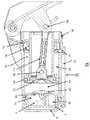
도 1은 본 발명의 일 실시예에 따른 개인용 여과 장치의 펌프 조립체 실시예를 도시한 사시도.
도 2는 도 1에 도시된 실시예의 펌프 조립체를 도시한 측면도.
도 3은 도 1에 도시된 실시예의 펌프 조립체를 도시한 평면도.
도 4는 도 1에 도시된 실시예를 도시한 측단면도.
도 5는 도 1에 도시된 장치 실시예의 펌프 헤드 조립체를 도시한 단면도.
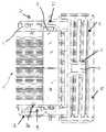
도 6은 도 1에 도시된 실시예의 필터 카트리지 및 유동 분리 단부 캡을 도시한 단면도.
도 7은 도 1에 도시된 실시예의 필터 카트리지 및 유동 분리 단부 캡을 상세하게 도시한 부분 단면도.
도 8은 도 1에 도시된 실시예의 플러시 밸브 및 유량 조절 밸브를 도시한 측면도.
도 9는 도 1에 도시된 실시예의 플러시 밸브 및 유량 조절 밸브의 단면도.
도 10은 도 1에 도시된 실시예의 펌프 헤드 조립체 내에 형성된 플러시 유체 통로를 도시한 단면도.
도 11은 도 1에 도시된 실시예의 펌프 헤드 조립체와 결합될 수 있는 프리 필터 및 이중 루멘 호스 조립체를 도시한 도면.1 is a perspective view showing an embodiment of a pump assembly of a personal filtration device according to an embodiment of the present invention.
Fig. 2 is a side view of the pump assembly of the embodiment shown in Fig. 1;
Fig. 3 is a plan view of the pump assembly of the embodiment shown in Fig. 1;
Fig. 4 is a side cross-sectional view showing the embodiment shown in Fig. 1;
Fig. 5 is a cross-sectional view of the pump head assembly of the device embodiment shown in Fig. 1;
Fig. 6 is a cross-sectional view of the filter cartridge and flow separation end cap of the embodiment shown in Fig. 1;
Fig. 7 is a partial cross-sectional view of the filter cartridge and flow separation end cap of the embodiment shown in Fig. 1 in detail;
Fig. 8 is a side view showing a flush valve and a flow control valve of the embodiment shown in Fig. 1;
Fig. 9 is a cross-sectional view of the flush valve and flow control valve of the embodiment shown in Fig. 1;
FIG. 10 is a cross-sectional view of a flush fluid passage formed within the pump head assembly of the embodiment shown in FIG. 1; FIG.
11 shows a pre-filter and dual lumen hose assembly that may be combined with the pump head assembly of the embodiment shown in FIG.
실시예의 특징에 의하면, 실시예의 개인용 여과 장치(1)가 도 1 내지 도 4에 도시된다. 도 1 내지 도 3은 개인용 여과 장치(1)의 외부를 도시하고, 도 4는 필터 카트리지(10) 내부의 유체 이동을 설명하기 위해 장치의 단면을 도시한다. 개인용 여과 장치(1)는 잠재적으로 미생물 병원체를 포함한 물 또는 다른 유체의 정화에 이용될 수 있다. 특히, 상기 개인용 여과 장치(1)는 작고 가벼우므로 미개척지 또는 국제적으로 여행하는 등산객, 야영 자, 등산객, 등산가 및 전방에 배치된 전투원과 같은 사람들이 이용할 수 있다.According to an embodiment feature, an embodiment
도 1 내지 도 6에 도시된 것처럼, 상기 개인용 여과 장치(1)는 펌프 헤드 조립체(73)가 레버 작동 핸들(3)을 이동시킴으로써 여과될 유체를 펌프 몸체(2)로 전달하는 수단을 제공하도록 구성 및 설계된다. 여과되어야 하는 유체(유입 유동)는, 유입구 조립체(8) 상에 장착된 유입구 포트(4)를 통해 펌프 헤드 조립체(73)속으로 들어간다. 유입구 포트(4)는 임의 형태의 적합한 유체 연결 포트 일 수 있다. 필터 카트리지(10)는 펌프 몸체(2)의 챔버 내에 수용된다. 가압된 유체는 통로(65)를 통해 펌프 헤드 조립체(73)를 배출시키고 유입 유체 공동(즉, 덕트(duct))(11)을 통해 필터 카트리지(10)로 가로질러 이동한다. 유체가 플러시 - 유체 공동(41), 플러시 밸브 또는 유량 조절 밸브(30) 및 플러시 - 배출 공동(42)을 먼저 통과한 후에, 플러시 포트(5)를 통해 필터 카트리지(10)를 통과되지 못한 수인성 오염물을 제거하기 위한 플러시 유체가 플러시 포트(5)를 통해 방출된다. 플러시 밸브 또는 유동 조절 밸브(30)는 필터 카트리지(10)를 통과하는 플러시 유체의 유속을 제어하고 또한 미리 정해진 크기를 초과하는 여과 압력을 완화시킨다. 상기 플러시 포트(5)는 모든 형태의 적합한 유체 연결 포트 일 수 있다. 유입구 포트(4)는 상기 플러시 포트(5)와 근접하게 배열되고, 양 포트들은, 펌프 헤드 커버(9)에 의해 기계적으로 보호된다. 상기 필터 카트리지(10)에 의해 생성된 여과된 유체(유출 유동)는 유동 분리 단부 캡(16)을 통과한 후에 유출구 포트(18)를 통해 방출된다(도 6). 원한다면, 컨테이너가 상기 유동 분리 단부 캡(16)에 나사 연결되어 여과된 유체를 수집할 수 있다. 상기 장치가 이용되지 않을 때 유출구 포트(18)의 오염을 방지하기 위해, 상기 유동 분리 단부 캡(16)은 제거 가능한 캡(6)에 의해 캡슐화될 수 있다.1-6 , the
도 11을 참고할 때, 프리 필터(prefilter) 및 이중 루멘(double lumen) 호스 조립체가 도시된다. 유연한 이중 루멘 유체 호스(70)는, 여과되는 유체 및 개인용 여과 장치(1) 사이에서 유체 도관을 제공한다. 상기 이중 루멘 호스의 유입 측부(71)는 입구 포트(4)에 연결되고 유체 공급원(예를 들어, 유동, 크릭(creak) 등)으로부터 추출된 미여과 유체를 위한 도관으로서 이용된다. 이중 루멘 튜빙의 방출 측부(72)는 플러시 포트(5)에 연결되고, 여과 공정 동안 필터 카트리지(10) 내부에 형성된 막힘 재료(clogging material)를 제거하기 위한 플러시 유체를 정화되는 유체의 공급원으로 전달하기 위한 도관으로서 이용된다. 유체 호스의 가요성에 의해 상기 개인용 여과 장치(1)가 사용되지 않을 때 펌프 몸체(2) 둘레에 호스가 용이하게 감기게 된다. 이중 루멘 유체 호스를 제조하기 위해 상업적으로 이용 가능한 예시적인 재료는, 고무, 실리콘, 폴리에틸렌 또는 당 업계에 공지된 다른 가요성 재료를 포함한다. 루멘 유체 호스(70)의 유입 측부(71)는, 잎, 나뭇가지, 다량의 침전물 조각 등과 같은 큰 치수의 입자가 상기 유입 측부속으로 들어가는 것을 방지하기 위한 스크린 또는 메시로 구성된 프리 필터 조립체(80)에 부착된다. 상기 스크린 또는 메쉬는 친수성을 가져서 공기가 시스템속에 포착되는 것을 최소화할 수 있다.Referring to FIG. 11 , a prefilter and double lumen hose assembly is shown. A flexible double lumen fluid hose 70 provides a fluid conduit between the fluid being filtered and the
도 5를 참고하면, 펌프 헤드 조립체(73)의 측면 단면도가 도시된다. 도시된 실시예에서, 상기 펌프 헤드 조립체(73)는 이중 작동(이중 작용) 펌프이다. 유체는 유입구 포트(4)를 통해 흡인되고, 피스톤(51)이 양방향으로 움직일 때 필터 카트리지(10)에 유체 연결(fluidly coupled)되는 가압 유체 유출구 공동(65)을 통해 배출된다. 상기 이중 작동 펌프는, 여과되지 않은 유체의 거의 연속적인 유동을 필터 카트리지(10)로 전달하기 때문에 유리하다. 대조적으로, 원격 위치에서 물을 정화하기 위해 개발된 대부분의 개인용 핸드 펌프 작동식 필터는 단일 작동(single acting) 펌프 설계를 이용한다. 단일 작동식 핸드 펌프 필터의 작동원리에 의하면, 피스톤/플런저가 챔버로부터 분리될 때 유체는 아웃 스트로크(out stroke)(상향 행정(upstroke))에 의해 펌프 헤드속으로 들어가고 다음에 인 스트로크(in stroke)(다운 스트로크(down stroke))에 의해 상기 피스톤/플런저에 의해 필터를 통과한다.Referring to FIG. 5 , a cross-sectional side view of the
상기 펌프 헤드 조립체(73)는 펌프 몸체(50), 피스톤(51) 및 피스톤 로드(66)를 포함한다. 상기 피스톤(51)과 마주보는 펌프 몸체(50)의 단부는 상기 피스톤 로드(66)의 자유로운 운동을 허용하기 위해 개방된다. 상기 피스톤 단부 너트(58)에 의해 상기 피스톤 로드(66)는 상기 펌프 몸체(50)내에서 전후로 이동할 수 있고, 상기 펌프 몸체내에서 상기 피스톤 로드는 동심 위치에 유지된다. 상기 피스톤 단부 너트(58)는 O 링(59)을 피스톤 로드(66)에 고정시키고 O 링(60)을 펌프 몸체(50)에 고정시켜서 상기 피스톤 로드(66)는 상기 펌프 헤드 조립체(73)내에 수용된 가압 유체가 전혀 누출되지 않고 상기 펌프 몸체내에서 전후로 효과적으로 이동할 수 있다. 상기 레버 작동 핸들(3)이 이동하여 상기 펌프 몸체(50)에 대해 피스톤(51)이 작동한다. 상기 레버 작동 핸들은 피봇 위치(7)에서 상기 펌프 헤드(50)에 대해 피봇 운동하게 장착된다. 상기 레버 작동 핸들(3)은 피봇 위치(56) 및 피봇 위치(55)에서 링크(54)를 통해 피스톤(51)에 피봇 운동하게 장착된다. 상기 펌프 헤드 조립체(73)는 또한, 상기 펌프 헤드 조립체(73)내에 배열되고 유체 공동(61) 및 플러시 방출 공동(42)을 포함한 유입구 조립체(8)를 포함한다.The
펌프 헤드 조립체(73) 내에서 유체가 이동하는 유동 경로는 피스톤(51)의 운동에 의존한다. 상기 레버 작동핸들(7)이 펌프 몸체(50)로부터 멀어지게 이동하고 음의 유체 압력이 형성되는 업 스트로크 동안, 미여과 유체는 유입구 조립체(8)상에 위치한 유입구 포트를 통해 개인용 여과 장치속으로 들어가고 유입구 유체 공동(61)속으로 들어간다. 업 스트로크 동안, 펌프 유입구 공동내에 형성된 진공 압력에 의해 유체는 정상적으로 상기 우산 밸브 통로(62)를 막는 체크 밸브로서 작동하는 부드러운 우산 밸브(53)를 지나고 변형시키기 때문에, 미여과 유체는 우산 밸브 통로(62)를 통해 상기 펌프 유입구 공동(63)속으로 유동할 수 있다. 피스톤 컵 씰(piston cup seal)(52)에 에너지를 공급하고 유입구 공동(63)과 펌프 유출구 공동(64) 사이에 밀봉 부를 형성하는 상향 행정 동안 이전 스트로크로부터 펌프 유출구 공동(64)에 남아있는 유체는 가압되어 펌프 유출구 공동(64) 내에 포함된 가압 유체는 진공 압력을 가진 펌프 유입구 공동(63)속으로 들어갈 수 없다. 그러나, 이전 다운 스트로크로부터 여전히 펌프 유출구 공동(64) 내에 포함된 유체는, 펌프 헤드 조립체(73)를 빠져나와 필터 유입 통로(65)를 통과하여 필터 카트리지(10)에 도달하게 된다.The flow path through which the fluid travels within the
레버 작동 핸들(7)이 펌프 몸체(2)를 향해 이동하는 다운 스트로크 동안, 펌프 유체 공동(63) 내부에 형성된 양의 압력은 우산 밸브(53)를 밀폐 위치로 귀환시켜서 상기 펌프 유체 공동내에 포함된 모든 유체가 우산 밸브 통로(62)를 통해 유입구 유체 공동(61)에 전달되는 것을 방지한다. 하향 스트로크 동안, 우산 밸브(53)는 밀폐된 체크 밸브로서 작용한다. 상기 피스톤 컵 씰(52)이 단지 상향 행정 방향으로 에너지를 공급하기 때문에 펌프 유체 공동(63)의 유체는 하향 스트로크에서 가압되어 유체는 상기 피스톤 컵 씰을 우회하여 펌프 유체 공동(63)으로부터 펌프 유출구 공동으로 전달될 수 있다. 동시에, 펌프 유체 공동(63)으로부터 펌프 유출구 공동(64)으로 전달되는 유체의 체적은 필터 유입 통로(65)를 통해 필터 카트리지(10)에 도달한다.During the downstroke in which the lever actuation handle 7 moves towards the
가압 유체를 필터 카트리지(10)에 전달하는 기능을 수행할 수 있는 펌프 헤드 조립체에 관한 다수의 선택적 실시예들이 존재며 따라서 도시된 펌프 조립체(73)는 단지 본질적으로 예시적인 것이며 본 발명의 범위를 제한하지 않는다. 가압 된 유체를 전달하는 이러한 작용은, 피스톤을 한 방향으로 움직이면 유입구 포트(4)를 통해 펌프속으로 물질을 끌어당기고 피스톤을 반대 방향으로 움직이면 물질을 배출시키는 단순한 "단동(single acting)" 펌프 조립체를 이용하여 수행할 수 있다.There are numerous alternative embodiments of a pump head assembly capable of performing the function of delivering pressurized fluid to the
필터 카트리지(10) 및 유동 분리 종단 캡(16)의 측 단면도인 도 6 내지 도 7을 참고한다. 상기 필터 카트리지(10)는 물리적 차단기구를 이용하여 미여과 유체에 존재하는 미생물 병원균을 제거하고 복수의 중공 섬유 막(12), 유입 단부(13) 및 플러시 단부(28)를 포함한 여과요소를 포함하도록 설계된다. 도시된 것처럼, 반투과성(semi-permeable) 중공 섬유 막(12)의 번들은 필터 카트리지(10)의 축을 따라 종 방향으로 배열된다. 중공 섬유 막(12)은 폴리 우레탄, 에폭시, 또는 당업계에 공지된 다른 적절한 접착 재료에 의해 필터 카트리지(10)의 각 단부(13,28)에 포팅(potting)될 수 있다. 유입 단부(13) 및 플러시 단부(28)에서 중공 섬유 막(12)을 둘러싸는 포팅 재료는, 중공 섬유 막의 루멘을 노출시키기 위해 접착 재료를 트리밍 또는 절단하는 방식으로 제거될 수 있다.Reference is made to FIGS. 6-7 , which are cross-sectional side views of the
유동 분리 단부 캡(16)은, 가압 유체를 반경 방향을 따라 필터 카트리지(10)로 향하게 하는 유입 공동(11)의 적어도 하나의 L 자형 통로를 가진 필터 유입구 공동, 여과된 유체를 유동 분리기에 분배하기 위한 유출구 포트(27), 단부 캡내에 잔류할 수 있는 여과된 유체와 미여과 유체를 물리적으로 분리하기 위해 실린더 부분(14)에 대해 밀봉하는 유동 분리 O- 링(17,23), 상기 단부 캡을 상기 펌프 몸체(2)에 용이하게 부착하거나 분리하기 위한 그립(15) 및 오염물이 상기 여과 유체 통로속으로 들어가는 것을 방지하기 위한 분리가능한 캡(6)을 포함한다.The flow
상기 필터 카트리지(10)는 펌프 헤드 조립체(73)를 향하는 플러시 단부(28)를 포함한 펌프 몸체(2) 내에 위치한다. 상기 필터 카트리지(10)의 유입 단부(13)는, 분리되거나 영구적으로 부착될 수 있는 유동 분리 단부 캡(16)을 수용할 수 있는 크기를 가진다. 상기 플러시 유체 공동(41)은 필터 카트리지(10)의 플러시 단부(28)와 펌프 헤드 조립체(73) 사이에서 분리에 의해 형성된다. 필터 유입 통로(65)는 펌프 몸체(2)와 필터 카트리지(10) 사이에서 분리에 의해 형성된다. 상기 유동 분리 단부 캡(16)의 외부 나사(22)는 상기 펌프 몸체(2)에 대해 상기 필터 카트리지(10)를 기계적으로 고정한다. O- 링(17,23)은, L자 형상 통로에 따라 필터 유입 통로(65)를 통해 필터 유입 공동(11) 및 유입 단부(13)로만 이동하는 미여과 유체를 제한하여, 여과된 유체가 필터 카트리지(10)를 우회하여 여과된 유체 유출구 포트(18)를 통해 오염 없이 개인용 여과 장치를 빠져나갈 수 있다. O- 링(24)은 유체 분리 단부 캡(16)을 펌프 몸체(2)에 밀봉하고, O- 링(25)은 플러시 단부(28)에서 필터 카트리지(10)로부터 유출하는 플러시 유체가 펌프 헤드 조립체(73)의 기저부에 위치한 플러시 유체 공동(41)을 향하게 한다. O- 링(23)에 의해, 필터 유입 통로(65)를 통해 이동하는 미여과 유체가 여과 유체 환형부(26)속으로 누출되어 유출구 포트(18)를 통해 분배되는 여과된 유체를 오염시키지 못한다.The filter cartridge (10) is located within the pump body (2) with the flush end (28) facing the pump head assembly (73). The
상기 필터 유입 통로(65)를 통해 이동하는 미여과 유체는, 유동 분리 단부 캡(16) 상에 위치한 필터 유입 공동(11)을 통해 필터 카트리지(10)속으로 들어가고, 상기 필터 유입 공동은 유체를 유입 단부(13)에 위치한 중공 섬유 막(12)의 노출된 루멘을 향하게 한다. 상기 미여과 유체는 중공 섬유 막(12)의 루멘을 통해 필터 카트리지(10)의 플러시 단부(28)를 향해 이동한다. 상기 중공 섬유 막(12)의 내부 및 외부 표면들사이에 형성된 압력차에 의해 미여과 유체는 반투막을 통해 필터 카트리지(10)내에 위치한 유출 공동(21)속으로 이동한다. 유출 공동(21)에서 수집된 여과된 유체는 개구부(27)를 통해 필터 카트리지(10)를 빠져나와 환형부(26)속으로 이동하고 유체가 유출구 캡(18)을 향하는 유동 분리 단부 캡(16)속으로 이동한다.Unfiltered fluid traveling through the filter inlet passageway 65 enters the
전통적인 수동식(hand operated) 개인용 여과 장치는, 필터 카트리지에 유입되는 모든 미여과 유체가 물리적 차단막을 통해 투과되어 여과된 유체로 변환되는 데드 엔드 여과 작동 모드를 이용한다. 상기 유동 구조에 의하면, 미여과 유체로부터 물리적 차단벽에 의해 제거되는 미립자 물질에 의해 형성된 필터 케이크가 상기 막을 막히게 하므로 불리하다. 개인용 여과 장치가 작동하는 동안 일부 단계에서, 막 표면 상에 형성된 필터 케이크를 물리적으로 제거하기 위해 수동 세정 단계가 개시되어야 한다. 실시예에 의하면, 필터 카트리지(10)속으로 들어가는 미여과 유체의 일부가 중공 섬유 막(12)의 전체 길이를 가로질러 이동하여 상기 미여과 유체의 일부는 중공 섬유 막의 개방 루멘을 통해 상기 필터 카트리지를 빠져나가도록 하여 상기 수동 세척 단계가 제거된다. 막 표면으로부터 중공 섬유에 의해 거부된 미립자 물질이 상기 플러시 유체에 의해 운반되기 때문에, 상기 플러시 - 유체 운동은 상기 루멘내에서 필터 케이크의 발생을 감소시킨다. 상기 필터 카트리지(10)를 빠져나가는 거부된 미립자 물질을 포함하는 플러시 유체는, 플러시 포트(5)를 통해 개인용 여과 장치로부터 배출되기 전에, 플러시 유체 공동(41), 유체 유출구 공동(42) 및 플러시 밸브(30)를 통과한다. 플러시 포트(5)를 통해 개인용 여과 장치를 빠져 나가는 미여과 유체 부분은 플러시 밸브(30)의 오리피스 치수에 의해 제어된다.Traditional hand operated personal filtration devices utilize a dead end filtration mode of operation in which all unfiltered fluid entering the filter cartridge is permeated through a physical barrier and converted to filtered fluid. This flow structure is disadvantageous because the filter cake formed by the particulate matter removed by the physical barrier from the unfiltered fluid clogs the membrane. At some stage during the operation of the personal filtration device, a manual cleaning step must be initiated to physically remove the filter cake formed on the membrane surface. According to an embodiment, a portion of the unfiltered fluid entering the
개인용 여과 장치의 구성에서 전형적으로 이용되고 미생물 병원체를 제거하기 위한 중공 섬유 막(12)은 구멍 치수에 따라 한외 여과막(ultrafiltration) 또는 미세 여과 막(microfiltration)으로 분류될 수 있다. 공개된 실시예에서, 중공 섬유막(12)은 한외 여과막 또는 미세 여과막일 수 있다. 0.05 미크론 미만의 구멍 크기 및 바람직하게는 0.015 내지 0.025 미크론의 구멍 크기를 가진 한외 여과 중공 섬유 막은, 미생물로 오염된 수원에서 바이러스, 박테리아 및 원충낭을 제거할 수 있는 물리적 장벽으로 이용된다. 0.05 미크론 초과 및 선호적으로 0.1 내지 0.3 미크론의 구멍 크기를 가진 미세 여과 중공 섬유 막은, 오염된 수원으로부터 박테리아 및 원충낭을 제거할 수 있는 물리적 장벽으로 이용된다. 중공 섬유 막이 가지는 구멍 크기와 무관하게, 양자 막들은 처리된 물의 기호성에 부정적 영향을 미치지 않으면서 식수를 생산할 수 있다. 예를 들어 상업적으로 이용가능한 중공 섬유 막은, 폴리설폰, 폴리 에테르 설폰, 셀룰로스 또는 수질 정화에 적합한 다른 재료로 구성된다. 중공 섬유 막은 300 내지 1,000 미크론의 외경을 가져야 하고, 바람직하게는 350 내지 500미크론의 외경을 가져야 한다. 중공 섬유 막의 벽 두께는 50 내지 200 미크론, 바람직하게는 50 내지 100미크론이어야 한다.The
중공 섬유 막을 이용하는 전통적인 수동식 개인용 여과 장치에서, 필터 카트리지는 친수성 및 소수성 중공 섬유 막들의 이종 조합으로 구성된다. 친수성 중공 섬유 막은 물과 같은 유체를 여과하기에 적합하지만 필터 카트리지 내부에 포착된 공기를 제거하기 위한 경로를 제공하지 못한다. 공개된 실시예에서, 상기 포착된 공기를 필터 카트리지로부터 제거하기 위한 대체 경로가 제공되기 때문에, 필터 카트리지(10)는 친수성 중공 섬유 막(12)으로만 구성된다. 중공 섬유 막(12)의 루멘 내부에 포착된 공기는 플러시 유체가 상기 중공 섬유 막의 전체 길이를 가로질러 이동할 때 상기 막을 자가 세정하기 위해 이용되는 상기 플러시 유체에 의해 운반될 수 있다. 플러시 유체와 함께 상기 포착된 공기는, 마지막으로 상기 플러시 포트(5)를 통해 개인용 여과 장치로부터 배출되기 전에, 필터 카트리지(10)를 빠져나와 유체 유출구 공동(42)으로 배출된다. 작동과 관련하여, 개인용 여과 장치가 현장에서 이용되기 전에 적합한 작동을 위해 우선 상기 포착된 공기를 "블리딩(bleeding)"하여 상기 포착된 공기를 제거하도록 필터 카트리지(10)는 준비될 필요가 없다.In traditional passive personal filtration devices using hollow fiber membranes, the filter cartridge consists of a heterogeneous combination of hydrophilic and hydrophobic hollow fiber membranes. Hydrophilic hollow fiber membranes are suitable for filtering fluids such as water, but do not provide a path for removing air trapped inside the filter cartridge. In the disclosed embodiment, the
일 실시예에 의하면, 상기 유동 분리 단부 캡(16)은 개인용 여과 장치(1)를 여과된 유체가 배출될 수 있는 용기에 회전 가능하게 연결하기 위한 메커니즘을 제공한다. 상응하는 나사구조의 상부를 가진 용기가 상기 유동 분리 단부 캡(16)의 나사부분(19)속으로 간단히 나사 결합 될 수 있다. 따라서, 상기 용기를 고정하기 위한 별도의 사람이 필요 없고, 물을 여과하는 동안 필터를 용기위에 직접 고정할 필요없다. 선택적으로, 가요성 유체 호스가, 여과된 유체를 배출하기 위해 유출구 포트(18)의 외부에 배열된 가시(barb)형상부(20)상에 삽입 될 수 있다.According to one embodiment, the flow
플러시 밸브(30)를 도시하는 도 8 내지 도 10을 참고할 때, 상기 플러시 밸브는 상기 개인용 여과 장치(1)가 정상적으로 작동하는 동안 필터 카트리지(10)를 빠져나가는 플러시 유체의 체적을 제어하고 필터 카트리지 내부에서 미리 정해진 수준을 초과하여 증가되는 압력을 완화시킨다. 상기 압력 증가는 일반적으로 필터 카트리지(10) 내부의 막힘 또는 다른 유형의 장애에 의해 발생되어 상기 필터 카트리지를 통해 물의 정상적인 유동을 방해할 수 있다. 상기 펌프 헤드 조립체(73)의 기저부에 배열된 플러시 밸브(30)는 플러시 유체 공동(41) 및 유출구 공동(42)과 유압에 의해 연결된다. 상기 플러시 밸브(30)는 면 밀봉체(face seal)(31)을 수용하는 하우징(32), 유체 공동(41)으로부터 플러시 밸브로 들어가는 유체의 유동을 제한하는 유동 제한 오리피스(40), 밸브 스프링(34) 상에 장착되고 영구적으로 부착된 캡(33) 및 유입구 조립체(8)에 대해 상기 플러시 밸브를 고정하는 베이요넷(bayonet) 유지 커넥터(37)를 포함한 외부 밸브 캡(35)을 포함한다. O 링(39)은 장착 표면(36)상의 플러시 밸브(30)의 주변부에 고정되어, 플러시 밸브와 유입구 조립체(8) 사이의 공간을 밀봉하고, 채널 유체는 통로(43)를 통해서만 플러시 유체 유출구 공동(42)속으로 이동한다.8-10, which show a
정상적으로 작동하는 동안, 상기 면 밀봉체(31) 및 밀봉 표면(38)사이에 밀봉을 형성하기 위해 미리 정해진 편향 하중을 제공한다. 정상적으로 작동하는 동안, 플러시 유체 공동(41)속으로 들어가는 모든 유체는 가압되어 유동 제한 오리피스(40)를 통과한다. 플러시 유체 공동(41)으로부터 상기 플러시 포트(5)를 통해 방출되는 미여과 유체 비율이 유입되는 유체의 1 내지 30%, 바람직하게는 5 내지 10% 이도록 유동 제한 오리피스(40)의 기하학적 형상이 정해진다. 그러나, 필터 카트리지(10) 내부의 유체 압력이 미리 정해진 안전 레벨을 초과하면, 상기 밸브 스프링(34)에 의해 밀봉부(31)는 밀봉표면(38)으로부터 적어도 부분적으로 방출되어 상대적으로 크거나 적게 제한된 유동 경로를 형성한다. 결과적으로, 플러시 포트(5)를 통해 방출되는 미여과 유체의 비율은, 중공 섬유 막(12)을 통해 유체가 유동하는 것을 방해할 수 있는 필터 카트리지(10) 내부의 장애물을 제거하기 위해 일시적으로 증가된다. 밀봉부(31) 및 밀봉 표면(38)사이에 형성되고 통로(43)를 통해 유출구 공동(41)으로 유동하며 상대적으로 덜 제한된 유동 경로(100)뿐만 아니라 제한 오리피스(40)를 통해 유체 공동(41)으로 플러시 유체가 유동할 수 있다. 필터 카트리지(10) 내부의 유체 압력이 미리 정해진 크기 미만으로 귀환할 때에만 상기 밸브 스프링(34)은 밀봉표면(38)과 완전히 재결합되어, 플러시 유체는 제한 오리피스(40)를 통해서만 이동하게 된다.During normal operation, a predetermined biasing load is applied to form a seal between the
필터 카트리지(10)의 사용 수명 동안, 플러시 포트(5)로부터 필터 케이크의 상당 부분을 운반하는 유체 플러싱 기구에도 불구하고 상기 중공 섬유 막(12)은 미립자를 축적하기 시작한다. 결과적으로, 공동(41) 내부의 압력은 증가하지만, 여전히 릴리프 밸브 스프링(34)을 작동시키기 위한 미리 정해진 레벨 아래로 유지된다. 공동(41) 내부의 압력은 공동(44) 내부의 압력과 동일할 수 있다. 상기 압력은 유량 조절 밸브(45)의 면에 작용한다. 상기 유량 조절 밸브(45)는 고무 또는 폴리 우레탄과 같은 중합체 재료로 구성될 수 있다. 공동(44) 내부의 압력이 증가함에 따라, 유동 조절 밸브(45)는 변형되고 유동 오리피스(40)의 직경은 감소한다. 정상 작동 범위의 압력에 의해 선호적으로 유입구 유동의 5% 및 10%의 유체 플러시 바이 패스 체적(fluid flush bypass volume)이 형성되도록 유동 조절 밸브(45)가 조정될 수 있다.During the service life of the
상기 설명으로부터, 본 발명의 특정 실시예가 설명을 위해 제공되지만 본 발명의 사상 및 범위를 벗어나지 않고 다양한 변형이 이루어질 수 있음을 이해할 것이다. 따라서, 본 발명은 첨부된 청구 범위를 제외하고는 제한되지 않는다.From the above description, it will be understood that, although specific embodiments of the present invention are provided for purposes of illustration, various modifications may be made without departing from the spirit and scope of the present invention. Accordingly, the invention is not limited except by the appended claims.
1......개인용 여과 장치,
73......펌프 헤드 조립체,
3......레버 작동 핸들,
2......펌프 몸체,
8......유입구 조립체,
4......유입구 포트,
10......필터 카트리지,
65......통로,
11......유입 유체 공동,
41......플러시 유체 공동,
30......유량 조절 밸브,
42......플러시 배출 공동,
5......플러시 포트,
18......유출구 포트,
16......유동 분리 단부 캡.1.......Personal filtration device,
73......pump head assembly,
3......Lever operated handle,
2......pump body,
8......Inlet assembly,
4......Inlet port,
10......Filter cartridge,
65 . . . Aisle,
11......inlet fluid cavity;
41......Flush fluid cavity,
30......flow control valve,
42......Flush exhaust cavity;
5......Flush port,
18......Outlet port,
16......Flow separation end caps.
Claims (19)
Translated fromKorean미여과 유체를 수용하기 위한 유입구 포트,
상기 유입구 포트와 유체에 의해 연결되고, 중공 섬유 막 모듈 형태의 여과 매체를 포함한 여과 부분,
상기 여과 부분과 유체에 의해 연결되고, 여과된 유체를 분배하기 위한 여과된 액체의 유출구 포트,
상기 여과 부분과 유체에 의해 연결된 플러시 포트 - 상기 플러시 포트는 중공 섬유 막을 통해 침투하지 못하는 입자 물질을 포함한 플러시 유체를 방출함 - ;
상기 유입구 포트, 여과 부분, 유출구 포트 및 플러시 포트와 유체에 의해 연결되는 수동식 펌프 조립체 - 상기 펌프 조립체가 작동할 때 상기 펌프 조립체는 유입구 포트에서 음의 유체 압력을 형성하고 유출구 포트 및 플러시 포트에서 양의 유체 압력을 형성함 - ,
여과 부분 및 플러시 포트에 유체에 의해 연결된 유량 조절 밸브(45) - 상기 유량 조절 밸브는 중공 섬유 막 모듈의 섬유의 압력 증가에 응답하여 직경이 감소하도록 구성된 오리피스(40)를 가짐 - 를 포함하고,
상기 유량 조절 밸브는 엘라스토머 재료로 형성되고,
상기 펌프 조립체의 작동에 의해, 상기 여과 부분은 상기 유입구 포트로부터 미여과 액체를 수용하고 상기 유출구 포트는 상기 여과 부분으로부터 제1방향을 따라 상기 여과 매체를 가로질러 이동하는 액체만 수용하고 상기 플러시 포트는 상기 여과 부분으로부터 상기 제1방향과 다른 제2방향을 따라 상기 여과 매체를 가로 질러 이동하는 액체를 수용하는 것을 특징으로 하는 마실 수 있는 액체의 여과장치.
A filtration device for drinkable liquids, comprising:
an inlet port for receiving unfiltered fluid;
A filtration part connected with the inlet port by a fluid and comprising a filtration medium in the form of a hollow fiber membrane module,
an outlet port of the filtered liquid connected by a fluid with the filtering portion for dispensing the filtered fluid;
a flush port fluidly connected with the filtration portion, the flush port discharging a flush fluid comprising particulate matter impermeable through the hollow fiber membrane;
a manual pump assembly fluidly connected with the inlet port, the filtration portion, the outlet port and the flush port, wherein when the pump assembly is actuated, the pump assembly creates a negative fluid pressure at the inlet port and positive at the outlet port and the flush port - to form a fluid pressure of ,
a flow control valve (45) fluidly connected to the filtration portion and the flush port, the flow control valve having an orifice (40) configured to decrease in diameter in response to an increase in pressure in the fibers of the hollow fiber membrane module;
The flow control valve is formed of an elastomeric material,
By operation of the pump assembly, the filtration portion receives unfiltered liquid from the inlet port and the outlet port receives only liquid moving across the filtration medium from the filtration portion in a first direction and the flush port contains liquid moving across the filtration medium from the filtration portion along a second direction different from the first direction.
2. The beverage of claim 1, wherein said pump assembly comprises a piston, said piston forcing liquid through said filtration portion to said flush port and outlet port as the piston performs an upstroke and a downstroke. filtration of liquids.
The system of claim 1 , further comprising a suction hose assembly, the hose assembly having a first lumen connected to the inlet port at a proximal end, a second lumen connected to the flush port at a proximal end and distal ends of the lumens. and a screen associated with said first and second lumens.
The apparatus of claim 1 , wherein the first and second directions are substantially orthogonal to each other.
The device of claim 1 , wherein the filtering portion has a proximal end and a distal end, the inlet port and the flush port being arranged at the proximal end.
6. A device according to claim 5, characterized in that the outlet port is arranged at the distal end.
2. The apparatus of claim 1, further comprising first and second ducts respectively fluidly connecting the flush port and the outlet port to the filtering portion.
2. The device of claim 1, further comprising a threaded end cap surrounding said outlet port.
상기 여과 부분은 길이를 가진 적어도 한 개의 투과성 막을 포함하며,
상기 펌프 조립체의 작동에 의해, 상기 여과 부분은 상기 유입구 포트로부터 미여과 액체를 수용하고 상기 유출구 포트는 상기 여과 부분으로부터 상기 막을 투과한 액체만 수용하고 상기 플러시 포트는 상기 여과 부분으로부터 상기 막의 길이를 가로질러 이동하는 액체를 수용하는 것을 특징으로 하는 마실 수 있는 액체의 여과장치.
The method of claim 1,
the filtering portion comprises at least one permeable membrane having a length;
By operation of the pump assembly, the filtration portion receives unfiltered liquid from the inlet port and the outlet port receives only the liquid that has permeated the membrane from the filtration portion and the flush port measures the length of the membrane from the filtration portion A device for filtering drinkable liquids, characterized in that they contain liquids that move across.
10. The drinking water of claim 9, wherein said pump assembly includes a piston, said piston forcing liquid through said filtering portion to said flush port and outlet port as the piston performs an upstroke and a downstroke. filtration of liquids.
10. The method of claim 9, further comprising a suction hose assembly, the hose assembly having a first lumen connected to the inlet port at a proximal end, a second lumen connected to the flush port at a proximal end and distal ends of the lumens. and a screen associated with said first and second lumens.
10. A device according to claim 9, wherein the filtering portion has a proximal end and a distal end, and wherein the inlet port and the flush port are arranged at the proximal end.
13. The device of claim 12, wherein the outlet port is arranged at the distal end.
10. The apparatus of claim 9, further comprising first and second ducts respectively fluidly connecting the flush port and the outlet port to the filtering portion.
10. The apparatus of claim 9, further comprising a threaded end cap surrounding the outlet port.
Applications Claiming Priority (3)
| Application Number | Priority Date | Filing Date | Title |
|---|---|---|---|
| US201462083877P | 2014-11-24 | 2014-11-24 | |
| US62/083,877 | 2014-11-24 | ||
| PCT/US2015/062515WO2016086048A1 (en) | 2014-11-24 | 2015-11-24 | Portable liquid-filtration device |
Publications (2)
| Publication Number | Publication Date |
|---|---|
| KR20170091662A KR20170091662A (en) | 2017-08-09 |
| KR102460815B1true KR102460815B1 (en) | 2022-10-28 |
Family
ID=56075000
Family Applications (1)
| Application Number | Title | Priority Date | Filing Date |
|---|---|---|---|
| KR1020177017475AActiveKR102460815B1 (en) | 2014-11-24 | 2015-11-24 | Portable liquid-filtration device |
Country Status (10)
| Country | Link |
|---|---|
| US (1) | US10391452B2 (en) |
| EP (1) | EP3223933B1 (en) |
| JP (1) | JP6802175B2 (en) |
| KR (1) | KR102460815B1 (en) |
| CN (1) | CN107106985B (en) |
| AU (1) | AU2015353600B2 (en) |
| CA (1) | CA2968674C (en) |
| HK (1) | HK1246726A1 (en) |
| PL (1) | PL3223933T3 (en) |
| WO (1) | WO2016086048A1 (en) |
Families Citing this family (7)
| Publication number | Priority date | Publication date | Assignee | Title |
|---|---|---|---|---|
| CN107522262A (en)* | 2016-06-21 | 2017-12-29 | 海南立昇净水科技实业有限公司 | A kind of integrating manual purifier with self power generation and automatic back-flushing function |
| CN109432857B (en)* | 2019-01-04 | 2024-06-07 | 河北上善若水智慧水务有限公司 | Portable water purification device |
| WO2020185520A1 (en) | 2019-03-08 | 2020-09-17 | Grayl Inc. | Self-back flushing filtration assembly |
| US10639659B1 (en)* | 2019-03-13 | 2020-05-05 | Chapin Manufacturing, Inc. | Backpack sprayer with internal pump |
| US10994294B2 (en) | 2019-03-13 | 2021-05-04 | Chapin Manufacturing, Inc. | Backpack sprayer with selectable internal pump |
| KR20220156611A (en)* | 2020-03-27 | 2022-11-25 | 오토마큐브 에스.알.엘. | Filtering groups for personal protection and isolation devices and protection and isolation devices against contaminants and microorganisms |
| CN114873778B (en)* | 2022-04-25 | 2023-08-11 | 安徽理工大学 | Coal slime water treatment system for coal washing and selecting processing |
Family Cites Families (17)
| Publication number | Priority date | Publication date | Assignee | Title |
|---|---|---|---|---|
| US4975185A (en) | 1989-05-08 | 1990-12-04 | Separation Dynamics, Inc. | Portable water purification system |
| US5431816A (en) | 1991-04-09 | 1995-07-11 | Sweetwater, Inc. | Prefilter for a water purification pump |
| US5266196A (en) | 1991-07-19 | 1993-11-30 | Mountain Safety Research, Inc. | Water filter |
| WO1993002781A1 (en) | 1991-08-02 | 1993-02-18 | Astroa Pty. Limited | Portable water purification system |
| US5531887A (en)* | 1995-05-24 | 1996-07-02 | Howell Laboratories, Inc. | Manually operated reverse osmosis desalinization system |
| WO1997006878A1 (en) | 1995-08-11 | 1997-02-27 | Katadyn Produkte Ag | Compact portable hand-operated filter for purifying water |
| JP4445862B2 (en)* | 2002-09-27 | 2010-04-07 | 三菱レイヨン株式会社 | Hollow fiber membrane module, hollow fiber membrane module unit, membrane filtration device using the same, and operating method thereof |
| US7534349B2 (en) | 2005-09-02 | 2009-05-19 | Nephros, Inc. | Dual stage ultrafilter devices in the form of portable filter devices, shower devices, and hydration packs |
| GB2443608B (en) | 2006-09-25 | 2008-11-12 | Michael Pritchard | A water purifying device |
| US8281937B2 (en) | 2007-02-16 | 2012-10-09 | Nephros, Inc. | Compact fluid purification device with manual pumping mechanism |
| WO2008115587A1 (en) | 2007-03-20 | 2008-09-25 | Cascade Designs, Inc. | Portable fluid filtration device |
| US20100276614A1 (en)* | 2007-09-14 | 2010-11-04 | Daryll Duane Patterson | Modular in-line fluid regulators |
| GB0719983D0 (en)* | 2007-10-12 | 2007-11-21 | Isis Innovation | A portable water purification device |
| GB2473836A (en) | 2009-09-24 | 2011-03-30 | John Griffith | Water filter |
| US9010120B2 (en) | 2011-08-05 | 2015-04-21 | General Electric Company | Assemblies and apparatus related to integrating late lean injection into combustion turbine engines |
| EP2846893B1 (en)* | 2012-05-08 | 2017-08-23 | Nephros, Inc. | Apparatus with a flush pump feature for a portable liquid purifying filter |
| US8323490B1 (en)* | 2012-08-02 | 2012-12-04 | Instapure Brands, Inc. | Pressurized water filtration system |
- 2015
- 2015-11-24AUAU2015353600Apatent/AU2015353600B2/enactiveActive
- 2015-11-24KRKR1020177017475Apatent/KR102460815B1/enactiveActive
- 2015-11-24WOPCT/US2015/062515patent/WO2016086048A1/enactiveApplication Filing
- 2015-11-24CACA2968674Apatent/CA2968674C/enactiveActive
- 2015-11-24USUS15/528,973patent/US10391452B2/enactiveActive
- 2015-11-24PLPL15864124.1Tpatent/PL3223933T3/enunknown
- 2015-11-24EPEP15864124.1Apatent/EP3223933B1/enactiveActive
- 2015-11-24HKHK18104402.4Apatent/HK1246726A1/enunknown
- 2015-11-24CNCN201580072296.0Apatent/CN107106985B/enactiveActive
- 2015-11-24JPJP2017545879Apatent/JP6802175B2/enactiveActive
Also Published As
| Publication number | Publication date |
|---|---|
| JP6802175B2 (en) | 2020-12-16 |
| AU2015353600B2 (en) | 2020-09-17 |
| HK1246726A1 (en) | 2018-09-14 |
| JP2017535429A (en) | 2017-11-30 |
| EP3223933B1 (en) | 2024-02-28 |
| PL3223933T3 (en) | 2024-08-05 |
| AU2015353600A1 (en) | 2017-06-08 |
| EP3223933A1 (en) | 2017-10-04 |
| KR20170091662A (en) | 2017-08-09 |
| US10391452B2 (en) | 2019-08-27 |
| CA2968674C (en) | 2022-10-25 |
| CN107106985A (en) | 2017-08-29 |
| CN107106985B (en) | 2020-11-10 |
| EP3223933A4 (en) | 2018-07-18 |
| CA2968674A1 (en) | 2016-06-02 |
| US20170266621A1 (en) | 2017-09-21 |
| WO2016086048A1 (en) | 2016-06-02 |
| EP3223933C0 (en) | 2024-02-28 |
Similar Documents
| Publication | Publication Date | Title |
|---|---|---|
| KR102460815B1 (en) | Portable liquid-filtration device | |
| JP5532273B2 (en) | Hollow fiber hydrophilic capillary membrane and method | |
| KR101545363B1 (en) | Capillary membrane filter with manually activated backwash pump | |
| EP2512299B1 (en) | Drinking straw with hollow fibre liquid filter | |
| CA1245567A (en) | Hollow-fiber filtering module and water purification device utilizing it | |
| US20030164333A1 (en) | In-line hydration pack biological filter | |
| HU227884B1 (en) | Ultrafiltration and microfiltration module and system | |
| US12180094B2 (en) | Pool filtration system and method | |
| US20230087869A1 (en) | Hybrid filter assembly and method | |
| EP3668818A1 (en) | Water filter | |
| JP2012035175A (en) | Water purifying device | |
| CN208388083U (en) | A kind of water purification army pot with pressure-adjusting type super filter tube | |
| WO2017099999A1 (en) | Portable liquid-filtering dispenser | |
| HK1136264A (en) | A water purifying device | |
| CZ2016631A3 (en) | A portable set for water treatment and a method of its operation and a pump for this set and a method of its operation | |
| WO2017082829A1 (en) | Filtration apparatus |
Legal Events
| Date | Code | Title | Description |
|---|---|---|---|
| PA0105 | International application | St.27 status event code:A-0-1-A10-A15-nap-PA0105 | |
| PG1501 | Laying open of application | St.27 status event code:A-1-1-Q10-Q12-nap-PG1501 | |
| P11-X000 | Amendment of application requested | St.27 status event code:A-2-2-P10-P11-nap-X000 | |
| P13-X000 | Application amended | St.27 status event code:A-2-2-P10-P13-nap-X000 | |
| R15-X000 | Change to inventor requested | St.27 status event code:A-3-3-R10-R15-oth-X000 | |
| R16-X000 | Change to inventor recorded | St.27 status event code:A-3-3-R10-R16-oth-X000 | |
| PA0201 | Request for examination | St.27 status event code:A-1-2-D10-D11-exm-PA0201 | |
| E902 | Notification of reason for refusal | ||
| PE0902 | Notice of grounds for rejection | St.27 status event code:A-1-2-D10-D21-exm-PE0902 | |
| R17-X000 | Change to representative recorded | St.27 status event code:A-3-3-R10-R17-oth-X000 | |
| T11-X000 | Administrative time limit extension requested | St.27 status event code:U-3-3-T10-T11-oth-X000 | |
| E13-X000 | Pre-grant limitation requested | St.27 status event code:A-2-3-E10-E13-lim-X000 | |
| P11-X000 | Amendment of application requested | St.27 status event code:A-2-2-P10-P11-nap-X000 | |
| P13-X000 | Application amended | St.27 status event code:A-2-2-P10-P13-nap-X000 | |
| E701 | Decision to grant or registration of patent right | ||
| PE0701 | Decision of registration | St.27 status event code:A-1-2-D10-D22-exm-PE0701 | |
| GRNT | Written decision to grant | ||
| PR0701 | Registration of establishment | St.27 status event code:A-2-4-F10-F11-exm-PR0701 | |
| PR1002 | Payment of registration fee | St.27 status event code:A-2-2-U10-U12-oth-PR1002 Fee payment year number:1 | |
| PG1601 | Publication of registration | St.27 status event code:A-4-4-Q10-Q13-nap-PG1601 | |
| PR1001 | Payment of annual fee | St.27 status event code:A-4-4-U10-U11-oth-PR1001 Fee payment year number:4 |