KR102460756B1 - Camera Module - Google Patents
Camera ModuleDownload PDFInfo
- Publication number
- KR102460756B1 KR102460756B1KR1020150113483AKR20150113483AKR102460756B1KR 102460756 B1KR102460756 B1KR 102460756B1KR 1020150113483 AKR1020150113483 AKR 1020150113483AKR 20150113483 AKR20150113483 AKR 20150113483AKR 102460756 B1KR102460756 B1KR 102460756B1
- Authority
- KR
- South Korea
- Prior art keywords
- unit
- lens barrel
- optical axis
- camera module
- housing
- Prior art date
- Legal status (The legal status is an assumption and is not a legal conclusion. Google has not performed a legal analysis and makes no representation as to the accuracy of the status listed.)
- Active
Links
Images


Classifications
- H04N5/23212—
- G—PHYSICS
- G03—PHOTOGRAPHY; CINEMATOGRAPHY; ANALOGOUS TECHNIQUES USING WAVES OTHER THAN OPTICAL WAVES; ELECTROGRAPHY; HOLOGRAPHY
- G03B—APPARATUS OR ARRANGEMENTS FOR TAKING PHOTOGRAPHS OR FOR PROJECTING OR VIEWING THEM; APPARATUS OR ARRANGEMENTS EMPLOYING ANALOGOUS TECHNIQUES USING WAVES OTHER THAN OPTICAL WAVES; ACCESSORIES THEREFOR
- G03B5/00—Adjustment of optical system relative to image or object surface other than for focusing
- G—PHYSICS
- G03—PHOTOGRAPHY; CINEMATOGRAPHY; ANALOGOUS TECHNIQUES USING WAVES OTHER THAN OPTICAL WAVES; ELECTROGRAPHY; HOLOGRAPHY
- G03B—APPARATUS OR ARRANGEMENTS FOR TAKING PHOTOGRAPHS OR FOR PROJECTING OR VIEWING THEM; APPARATUS OR ARRANGEMENTS EMPLOYING ANALOGOUS TECHNIQUES USING WAVES OTHER THAN OPTICAL WAVES; ACCESSORIES THEREFOR
- G03B13/00—Viewfinders; Focusing aids for cameras; Means for focusing for cameras; Autofocus systems for cameras
- G03B13/32—Means for focusing
- G03B13/34—Power focusing
- G03B13/36—Autofocus systems
- G—PHYSICS
- G03—PHOTOGRAPHY; CINEMATOGRAPHY; ANALOGOUS TECHNIQUES USING WAVES OTHER THAN OPTICAL WAVES; ELECTROGRAPHY; HOLOGRAPHY
- G03B—APPARATUS OR ARRANGEMENTS FOR TAKING PHOTOGRAPHS OR FOR PROJECTING OR VIEWING THEM; APPARATUS OR ARRANGEMENTS EMPLOYING ANALOGOUS TECHNIQUES USING WAVES OTHER THAN OPTICAL WAVES; ACCESSORIES THEREFOR
- G03B17/00—Details of cameras or camera bodies; Accessories therefor
- G03B17/02—Bodies
- H—ELECTRICITY
- H04—ELECTRIC COMMUNICATION TECHNIQUE
- H04N—PICTORIAL COMMUNICATION, e.g. TELEVISION
- H04N23/00—Cameras or camera modules comprising electronic image sensors; Control thereof
- H04N23/50—Constructional details
- H04N5/2253—
- H04N5/23216—
- H04N5/23251—
- H04N5/23264—
Landscapes
- Physics & Mathematics (AREA)
- General Physics & Mathematics (AREA)
- Engineering & Computer Science (AREA)
- Multimedia (AREA)
- Signal Processing (AREA)
- Lens Barrels (AREA)
- Adjustment Of Camera Lenses (AREA)
Abstract
Translated fromKoreanDescription
Translated fromKorean본 발명은 자동초점기능과 손떨림보정기능을 겸비한 카메라 모듈에 관한 것이다.
The present invention relates to a camera module having both an auto focus function and an image stabilization function.
카메라 모듈은 자동초점기능을 구비한다. 아울러, 카메라 모듈은 손떨림에 따른 해상도 저하현상을 경감시키기 위해 손떨림 보정기능(OIS: Optical Image Stabilization)을 부가적으로 더 구비할 수 있다.The camera module has an autofocus function. In addition, the camera module may additionally further include an optical image stabilization (OIS) function in order to reduce resolution degradation caused by hand shake.
2가지 기능을 겸비한 카메라 모듈은 고해상도 촬영에 유리하다. 그러나 이러한 카메라 모듈은 내부 구조가 복잡하여 제작이 어렵다. 아울러, 이러한 카메라는 각각의 기능을 수행하는 액추에이터로 인해 소형화가 어렵다.A camera module with two functions is advantageous for high-resolution shooting. However, such a camera module is difficult to manufacture because of its complicated internal structure. In addition, it is difficult to miniaturize these cameras due to actuators that perform respective functions.
참고로, 본 발명과 관련된 선행기술로는 특허문헌 1이 있다.For reference, there is Patent Document 1 as a prior art related to the present invention.
본 발명은 제작 및 소형화가 용이한 카메라 모듈을 제공하는데 그 목적이 있다.An object of the present invention is to provide a camera module that is easy to manufacture and miniaturize.
상기 목적을 달성하기 위한 본 발명의 일 실시 예에 따른 카메라 모듈은 자동초점조정 유닛과 손떨림보정 유닛이 광축 방향으로 배치되도록 구성되어, 카메라 모듈의 조립 편의성을 향상시키고 카메라 모듈의 소형화를 가능케 할 수 있다.The camera module according to an embodiment of the present invention for achieving the above object is configured such that the automatic focus adjustment unit and the camera shake correction unit are arranged in the optical axis direction, thereby improving the assembly convenience of the camera module and enabling the miniaturization of the camera module have.
본 발명은 카메라 모듈의 소형화를 가능케 할 수 있다.The present invention may enable miniaturization of a camera module.
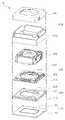
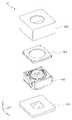
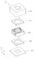
도 1은 본 발명의 일 실시 예에 따른 카메라 모듈의 분리 사시도
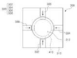
도 2는 일 실시 예에 따른 손떨림 보정 유닛의 구성도
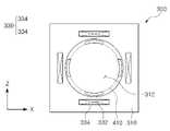
도 3은 다른 실시 예에 따른 손떨림 보정 유닛의 구성도
도 4는 도 1에 도시된 자동초점조정 유닛의 분리 사시도
도 5는 도 4에 액추에이터의 일 부분을 나타낸 사시도
도 6은 렌즈 배럴 홀더와 제2하우징의 결합 상태를 나타낸 사시도
도 7은 연결 유닛의 결합 형태를 나타낸 사시도
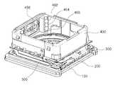
도 8은 카메라 모듈의 부분 결합 사시도
도 9는 본 발명의 다른 실시 예에 따른 카메라 모듈의 구성도
도 10은 본 발명의 또 다른 실시 예에 따른 카메라 모듈의 구성도1 is an exploded perspective view of a camera module according to an embodiment of the present invention;
2 is a block diagram of an image stabilization unit according to an embodiment;
3 is a configuration diagram of a hand shake correction unit according to another embodiment;
4 is an exploded perspective view of the auto-focusing unit shown in FIG. 1;
Figure 5 is a perspective view showing a portion of the actuator in Figure 4;
6 is a perspective view illustrating a coupling state between the lens barrel holder and the second housing;
7 is a perspective view showing the coupling form of the connection unit;
8 is a partially coupled perspective view of the camera module;
9 is a configuration diagram of a camera module according to another embodiment of the present invention;
10 is a configuration diagram of a camera module according to another embodiment of the present invention;
이하, 본 발명의 바람직한 실시 예를 첨부된 예시도면에 의거하여 상세히 설명한다.Hereinafter, a preferred embodiment of the present invention will be described in detail based on the accompanying illustrative drawings.
아래에서 본 발명을 설명함에 있어서, 본 발명의 구성요소를 지칭하는 용어들은 각각의 구성요소들의 기능을 고려하여 명명된 것이므로, 본 발명의 기술적 구성요소를 한정하는 의미로 이해되어서는 안 될 것이다.In describing the present invention below, terms referring to the components of the present invention are named in consideration of the functions of each component, and thus should not be construed as limiting the technical components of the present invention.
아울러, 명세서 전체에서, 어떤 구성이 다른 구성과 '연결'되어 있다 함은 이들 구성들이 '직접적으로 연결'되어 있는 경우뿐만 아니라, 다른 구성을 사이에 두고 '간접적으로 연결'되어 있는 경우도 포함하는 것을 의미한다. 또한, 어떤 구성요소를 '포함'한다는 것은, 특별히 반대되는 기재가 없는 한 다른 구성요소를 제외하는 것이 아니라 다른 구성요소를 더 포함할 수 있다는 것을 의미한다.
In addition, throughout the specification, that a component is 'connected' to another component includes not only a case in which these components are 'directly connected', but also a case in which the component is 'indirectly connected' through another component. means that In addition, 'including' a certain component means that other components may be further included, rather than excluding other components, unless otherwise stated.
도 1을 참조하여 일 실시 예에 따른 카메라 모듈을 설명한다.A camera module according to an embodiment will be described with reference to FIG. 1 .
카메라 모듈(10)은 이미지 센서 유닛(100), 필터 유닛(200), 손떨림보정 유닛(300), 자동초점조정 유닛(400), 하우징 유닛(600)을 포함한다. 그러나 카메라 모듈(10)의 구성이 전술된 유닛들로 한정되는 것은 아니다. 예를 들어, 카메라 모듈(10)의 구성으로부터 필터 유닛(200)을 배제시키는 것도 가능하다.The
이미지 센서 유닛(100)은 기판(110)과 이미지 센서(120)를 포함한다. 기판(110)과 이미지 센서(120)는 COB(Chip on Board) 방식으로 일체로 형성될 수 있다. 이 경우 이미지 센서 유닛(100)의 박형화가 용이하다.The
필터 유닛(200)은 필터 하우징(210), 필터(220)를 포함한다. 필터 하우징(210)에는 이미지 센서(120)로 입사되는 광량 조절을 위한 창(212)이 형성된다. 창(212)은 이미지 센서(120)의 형상 및 크기와 대체로 비례할 수 있다. 일 예로, 창(212)은 이미지 센서(120)와 마찬가지로 직사각 형태일 수 있다. 아울러, 창(212)의 크기는 이미지 센서(120)와 대체로 동일할 수 있다. 필터(220)는 카메라 모듈(10)의 선명한 화상 구현을 위해 구성된다. 일 예로, 필터(220)는 이미지 센서(120)로 입사되는 입사광으로부터 특정 파장의 광선(예를 들어, 적외선)을 차단할 수 있다.The
손떨림보정 유닛(300)은 자동초점조정 유닛(400)의 아래쪽에 배치된다. 그러나 손떨림보정 유닛(300)의 위치가 필터 유닛(200)과 자동초점조정 유닛(400) 사이로 한정되는 것은 아니다. 일 예로, 손떨림보정 유닛(300)은 자동초점조정 유닛(400)의 위쪽에 배치될 수도 있다.The hand
손떨림보정 유닛(300)은 자동초점조정 유닛(400)을 일 부분을 광축의 수직방향으로 움직이도록 구성된다. 일 예로, 손떨림보정 유닛(300)은 자동초점조정 유닛(400)의 렌즈 배럴을 광축의 제1수직방향으로 움직일 수 있다. 다른 예로, 손떨림보정 유닛(300)은 자동초점조정 유닛(400)을 광축의 제2수직방향으로 움직일 수 있다. 또 다른 예로, 손떨림보정 유닛(300)은 자동초점조정 유닛(400)의 렌즈 배럴을 광축의 제1수직방향과 제2수직방향으로 움직일 수 있다.The hand
손떨림보정 유닛(300)은 카메라 모듈(10)의 흔들림을 감쇄하는 방향으로 자동초점조정 유닛(400)을 움직일 수 있다. 일 예로, 손떨림보정 유닛(300)은 카메라 모듈(10)이 제1방향으로 이동하면, 자동초점조정 유닛(400)을 제1방향과 반대방향으로 이동시킬 수 있다. 다른 예로, 손떨림보정 유닛(300)은 카메라 모듈(10)이 제2방향으로 이동하면, 자동초점조정 유닛(400)을 제2방향과 반대방향으로 이동시킬 수 있다.The hand
손떨림보정 유닛(300)은 제1하우징(310) 및 접속 단자(320)를 포함한다. 제1하우징(310)은 자동초점조정 유닛(400)과 결합하기 위한 구성을 포함한다. 일 예로, 제1하우징(310)에는 자동초점조정 유닛(400)의 일 부분이 수용되는 수용부(312)가 형성된다.The
이와 같이 작동하는 손떨림보정 유닛(300)은 카메라 모듈(10)의 선명한 촬영을 가능케 할 수 있다.The hand
자동초점조정 유닛(400)은 카메라 모듈(10)의 초점조정이 가능하도록 구성된다. 일 예로, 자동초점조정 유닛(400)은 렌즈 또는 렌즈 배럴을 광축 방향으로 움직이도록 구성된다.The auto
하우징 유닛(600)은 카메라 모듈(10)을 유해 전자파 및 충격으로부터 보호하도록 구성된다. 이를 위해 하우징 유닛(600)은 금속재질로 제작될 수 있다. 그러나 하우징 유닛(600)의 재질이 금속으로 한정되는 것은 아니다. 일 예로, 하우징 유닛(600)은 금속 분말을 포함하는 수지 재질일 수도 있다.The
하우징 유닛(600)은 하부 하우징(610)과 상부 하우징(620)으로 분리될 수 있다. 일 예로, 하부 하우징(610)은 이미지 센서 유닛(100), 필터 유닛(200), 손떨림보정 유닛(300), 자동초점조정 유닛(400)을 수용하도록 구성될 수 있다. 그리고 상부 하우징(62)은 하부 하우징(610)의 상부를 덮도록 구성될 수 있다.
The
위와 같이 구성된 카메라 모듈(10)은 자동초점조정 유닛(400)과 손떨림보정 유닛(300)이 광축 방향으로 정렬된 구조를 갖는다. 따라서, 카메라 모듈(10)의 조립 및 제작이 용이할 수 있다. 아울러, 자동초점조정 유닛(400)과 손떨림보정 유닛(300)이 광축 방향으로 배치되므로, 자동초점조정 유닛(400) 또는 손떨림보정 유닛(300)의 부분적인 설계변경을 통해 카메라 모듈(10)의 박형화를 가능케 할 수 있다.
The
도 2를 참조하여 손떨림보정 유닛의 일 형태를 설명한다.One form of the image stabilization unit will be described with reference to FIG. 2 .
손떨림보정 유닛(300)은 자동초점조정 유닛(400)의 렌즈 배럴(410)을 움직이도록 구성된다. 일 예로, 손떨림보정 유닛(300)은 렌즈 배럴(410)을 광축의 수직방향(도 2 기준으로 X축 방향 및 Y축 방향)으로 움직일 수 있다.The hand
손떨림보정 유닛(300)은 제1하우징(310), 접속 단자(320), 제1액추에이터(330)를 포함한다. 제1하우징(310)에는 렌즈 배럴(410)의 일 부분을 수용하는 수용부(312)가 형성된다. 접속 단자(320)는 제1하우징(310)의 측면에 형성된다. 접속 단자(320)는 제1하우징(310)의 내부에 장착된 제1액추에이터(330)와 연결된다. 제1액추에이터(330)는 수용부(312)에 장착되는 렌즈 배럴(410)을 광축의 수직방향으로 움직이도록 구성된다. 일 예로, 액추에이터(330)는 공급되는 제어신호에 따라 신축 또는 신장 가능한 형상기억합금(332, 334, 336, 338)일 수 있다.The hand
형상기억합금(332, 334, 336, 338)은 수용부(312)를 중심으로 원형으로 배치된다. 이와 같이 배치된 형상기억합금(332, 334, 336, 338)은 제어신호에 따라 신장 또는 신축되어 렌즈 배럴(410)을 광축의 수직방향으로 밀어서 움직일 수 있다.
The
도 3을 참조하여 손떨림보정 유닛의 다른 형태를 설명한다.Another form of the image stabilization unit will be described with reference to FIG. 3 .
손떨림보정 유닛(300)은 다른 형태의 액추에이터(330)를 포함할 수 있다. 일 예로, 액추에이터(330)는 영구자석(332)과 코일(334)의 형태로 변경될 수 있다. 여기서, 영구자석(332)은 수용부(312)에 삽입되는 렌즈 배럴(410)에 배치되고, 코일(334)은 제1하우징(310)에 배치될 수 있다.The hand
이와 같이 구성된 액추에이터(330)는 영구자석(332)과 코일(334) 사이에 생성되는 자기력선의 방향 및 크기를 조정하여 렌즈 배럴(410)을 광축의 수직방향으로 움직일 수 있다.
The
도 4 및 도 5를 참조하여 자동초점조정 유닛을 설명한다.An auto-focusing unit will be described with reference to FIGS. 4 and 5 .
자동초점조정 유닛(400)은 렌즈 배럴(410), 렌즈 배럴 홀더(420), 제2하우징(420), 덮개(440), 제2액추에이터(450)를 포함한다. 그러나 자동초점조정 유닛(400)의 구성이 전술된 구성으로 한정되는 것은 아니다. 일 예로, 자동초점조정 유닛(400)는 복수의 베어링(562, 464, 466)을 더 포함할 수 있다.The auto-focusing
렌즈 배럴(410)은 하나 이상의 렌즈를 포함한다. 일 예로, 렌즈 배럴(410)은 광축을 따라 간격을 두고 배치되는 5매 이상의 렌즈를 포함할 수 있다. 그러나 렌즈 배럴(410)에 포함되는 렌즈의 매수가 5매로 한정되는 것은 아니다. 일 예로, 렌즈 배럴(410)은 4매 이하 또는 6매 이상의 렌즈를 포함할 수 있다.The
렌즈 배럴 홀더(420)는 렌즈 배럴(410)과 결합한다. 일 예로, 렌즈 배럴 홀더(420)는 렌즈 배럴(410)과 함께 광축 방향으로 이동하도록 구성될 수 있다. 렌즈 배럴 홀더(420)는 제2하우징(430)에 배치된다. 일 예로, 렌즈 배럴 홀더(420)는 제2하우징(430)의 내부에서 광축 방향으로 이동하도록 배치될 수 있다.The
렌즈 배럴 홀더(420)는 제2액추에이터(450)의 일 부분을 수용할 수 있다. 일 예로, 렌즈 배럴 홀더(420)의 일면에는 제2액추에이터(450)의 영구자석(452)이 배치될 수 있다.The
제2하우징(430)은 렌즈 배럴 홀더(420)를 수용하도록 구성된다. 일 예로, 제2하우징(430)의 내부에는 렌즈 배럴 홀더(420)보다 큰 수용 공간이 형성될 수 있다. 제2하우징(430)은 렌즈 배럴 홀더(420)의 광축 방향 이동이 가능하도록 형성된다. 일 예로, 제2하우징(430)의 상부 및 하부는 렌즈 배럴 홀더(420)가 이동할 수 있도록 개방되어 있다.The
제2하우징(430)은 제2액추에이터(450)의 작동이 원활하게 이루어질 수 있도록 구성된다. 일 예로, 제2하우징(430)의 일 측면은 제2액추에이터(450)의 영구자석(452)과 코일(456)이 마주할 수 있도록 개방된 개방 창(434)이 형성된다.The
덮개(440)는 제2하우징(430)과 결합하도록 구성된다. 일 예로, 덮개(440)의 걸쇠(442)는 제2하우징(430)의 쐐기(432)와 맞물릴 수 있다. 이와 같이 구성된 덮개(440)는 렌즈 배럴 홀더(420)가 제2하우징(430)으로부터 이탈하는 것을 차단할 수 있다.The
덮개(440)는 탄성 변형이 가능한 금속 재질로 제작될 수 있다. 따라서, 덮개(440)는 렌즈 배럴 홀더(420)과 충돌 과정에서 발생하는 충격을 흡수할 수 있다.The
덮개(440)에는 완충 부재(444)가 형성된다. 일 예로, 덮개(440)의 상면(도 4 기준임)에는 합성 수지, 고무 등의 재질로 이루어진 복수의 완충 부재(444)가 형성된다.A
완충 부재(444)는 덮개(440)와 함께 일체로 형성될 수 있다. 일 예로, 완충 부재(444)는 인서트 사출 등의 방식에 의해 덮개(440)에 견고하게 형성될 수 있다. 이와 같이 형성된 완충 부재(444)는 렌즈 배럴 홀더(420)와 덮개(440)의 충돌 시 발생하는 충격 및 충격음(소음)을 흡수할 수 있다.The
제2액추에이터(450)는 영구자석(452), 코일(456)을 포함한다.The
영구자석(452)은 자동초점조정 유닛(400)의 가동부분에 배치된다. 일 예로, 영구자석(452)은 렌즈 배럴 홀더(420)에 배치될 수 있다. 코일(456)은 자동초점조정 유닛(400)의 고정부분에 배치된다. 일 예로, 코일(456)은 제2하우징(420)에 배치될 수 있다.The
영구자석(452)과 코일(456)은 상호 마주보도록 배치된다. 영구자석(452)과 코일(456)은 광축과 대체로 평행한 방향으로 자기력을 발생시킬 수 있다. 영구자석(452)과 코일(456)에 의해 발생한 자기력은 렌즈 배럴(410) 및 렌즈 배럴 홀더(420)를 광축 방향으로 움직이기 위한 구동력으로 이용된다. The
제2액추에이터(450)는 기판(454)을 더 포함할 수 있다. 기판(454)은 제2하우징(430)의 개방 창(434)을 덮는 형태로 배치된다. 기판(454)에는 코일(456) 및 구동소자(458)가 형성된다. 또한, 기판(454)에는 코일(456)에 제어신호 및 전류를 공급하기 위한 접속 단자(455)가 형성된다.The
자동초점조정 유닛(400)은 렌즈 배럴 홀더(420)의 원활한 움직임을 가능케 하는 구성을 더 포함한다. 일 예로, 자동초점조정 유닛(400)은 베어링(462, 464, 466) 및 윤활제를 더 포함할 수 있다.The auto-focusing
베어링(462, 464, 466)은 렌즈 배럴 홀더(420)와 제2하우징(430) 사이에 배치된다. 일 예로, 베어링(462, 464, 466)은 렌즈 배럴 홀더(420) 또는 제2하우징(430)에 형성되는 안내 홈에 배치될 수 있다. 이와 같이 배치된 베어링(462, 464, 466)은 렌즈 배럴 홀더(420)와 제2하우징(430) 간의 접촉 마찰을 감소시킬 수 있다.
베어링(462, 464, 466)은 서로 다른 크기를 가질 수 있다. 일 예로, 베어링(462)과 베어링(466)은 동일한 크기를 가지나, 베어링(466)은 베어링(462, 466)보다 작은 크기를 가질 수 있다. 이러한 베어링(462, 464, 466)의 배치 형태는 베어링(462, 464, 466)의 구름 운동을 원활하게 할 수 있다.
도 6을 참조하여 렌즈 배럴 홀더와 제2하우징의 결합 형태를 설명한다.A coupling form of the lens barrel holder and the second housing will be described with reference to FIG. 6 .
렌즈 배럴 홀더(420)는 제2하우징(430)에 이동 가능하게 배치된다. 이를 위해 렌즈 배럴 홀더(420)와 제2하우징(430) 사이에는 베어링(462)이 배치될 수 있다. 참고로, 베어링(462)은 렌즈 배럴 홀더(420)의 안내 홈(428)과 제2하우징(430)의 안내 홈(438)에 의해 형성되는 공간에 배치될 수 있다.The
렌즈 배럴 홀더(420)는 광축 방향으로의 이동 범위를 한정하기 위한 구성을 포함한다. 일 예로, 렌즈 배럴 홀더(420)의 일 면(도 6 기준으로 상면)에는 스토퍼(422)가 형성된다. 상기 스토퍼(422)는 렌즈 배럴 홀더(420)의 상방으로 이동할 수 있는 범위를 제한할 수 있다.The
제2하우징(420)은 광축의 수직 방향으로의 이동 범위를 한정하기 위한 구성을 포함한다. 일 예로, 제2하우징(420)의 모서리 부분에는 광축의 수직 방향으로 연장되는 스토퍼(436)가 형성된다. 이와 같이 형성된 스토퍼(436)는 광축의 수직방향으로 이동할 수 있는 제2하우징(420)의 범위를 제한할 수 있다.
The
도 7을 참조하여 연결 유닛의 결합 형태를 설명한다.A coupling form of the connection unit will be described with reference to FIG. 7 .
연결 유닛(500)은 이미지 센서 유닛(100), 손떨림보정 유닛(300), 자동초점조정 유닛(400)을 연결한다. 일 예로, 연결 유닛(500)은 이미지 센서 유닛(100)으로부터 송출되는 제어신호에 의해 손떨림보정 유닛(300) 및 자동초점조정 유닛(400)이 작동할 수 있도록 이미지 센서 유닛(100), 손떨림보정 유닛(300), 자동초점조정 유닛(400)을 모두 연결할 수 있다.The
연결 유닛(500)은 휨 변형이 용이한 형태일 수 있다. 일 예로, 연결 유닛(500)은 가요성 기판 형태일 수 있다.
The
도 8을 참조하여 카메라 모듈의 결합 형태를 설명한다.A coupling form of the camera module will be described with reference to FIG. 8 .
카메라 모듈(10)은 이미지 센서 유닛(100), 필터 유닛(200), 손떨림보정 유닛(300), 자동초점조정 유닛(400)이 순차적으로 적층된 형태로 이루어진다. 이와 같이 구성된 카메라 모듈(10)은 박형화가 용이하다.The
카메라 모듈(10)은 이미지 센서 유닛(100), 손떨림보정 유닛(300), 자동초점조정 유닛(400)이 연결 유닛(500)에 의해 연결된 형태로 이루어진다. 연결 유닛(500)은 이미지 센서 유닛(100), 손떨림보정 유닛(300), 자동초점조정 유닛(400)이 측면을 감싸는 형태로 형성된다. 이러한 연결 유닛(500)의 배치 형태는 이미지 센서 유닛(100), 손떨림보정 유닛(300), 자동초점조정 유닛(400) 간의 접속 신뢰성을 향상시킬 수 있다.The
카메라 모듈(10)은 보호용 하우징을 포함한다. 일 예로, 이미지 센서 유닛(100), 필터 유닛(200), 손떨림보정 유닛(300), 자동초점조정 유닛(400)은 하부 하우징(610)의 내부에 수용되어, 외부 충격으로부터 보호될 수 있다.
The
다음에서는 카메라 모듈의 다른 실시 예를 설명한다. 참고로, 이하의 설명에서 전술된 실시 예와 동일한 구성요소는 전술된 실시 예와 동일한 도면부호를 사용하고, 이들 구성요소에 대한 상세한 설명은 생략한다.
Next, another embodiment of the camera module will be described. For reference, in the following description, the same components as those of the above-described embodiment use the same reference numerals as those of the above-described embodiment, and detailed descriptions of these components will be omitted.
도 9를 참조하여 다른 실시 예에 따른 카메라 모듈을 설명한다.A camera module according to another embodiment will be described with reference to FIG. 9 .
본 실시 예에 따른 카메라 모듈(10)은 필터 유닛(200), 손떨림보정 유닛(300), 자동초점조정 유닛(400)의 배치 순서에 있어서 구별될 수 있다. 일 예로, 카메라 모듈(10)은 손떨림보정 유닛(300), 자동초점조정 유닛(400), 필터 유닛(200)의 순으로 조립되도록 구성될 수 있다.The
이와 같은 형태의 카메라 모듈(10)은 손떨림보정 유닛(300)의 소형화 제작이 가능한 경우에 유리할 수 있다.
The
도 10을 참조하여 또 다른 실시 예에 따른 카메라 모듈을 설명한다.A camera module according to another embodiment will be described with reference to FIG. 10 .
본 실시 예에 따른 카메라 모듈(10)은 손떨림보정 유닛(300)의 구성에 있어서 구별될 수 있다. 일 예로, 손떨림보정 유닛(300)은 제1손떨림보정 유닛(302)과 제2손떨림보정 유닛(304)으로 분리될 수 있다.The
제1손떨림보정 유닛(302)은 자동초점조정 유닛(400)의 상면에 배치된다. 제1손떨림보정 유닛(302)은 자동초점조정 유닛(400)을 광축의 제1수직방향(도 10 기준으로 X축 방향)으로 움직이도록 구성된다.The first hand
제2손떨림보정 유닛(304)은 자동초점조정 유닛(400)의 하면에 배치된다. 제2손떨림보정 유닛(304)은 자동초점조정 유닛(400)을 광축의 제2수직방향(도 10 기준으로 Y축 방향)으로 움직이도록 구성된다.The second hand
이와 같이 구성된 카메라 모듈(10)은 제1손떨림보정 유닛(302) 또는 제2손떨림보정 유닛(304)의 선택적인 교체 및 교환이 가능하다.
The
본 발명은 이상에서 설명되는 실시 예에만 한정되는 것은 아니며, 본 발명이 속하는 기술분야에서 통상의 지식을 가진 자라면 이하의 특허청구범위에 기재된 본 발명의 기술적 사상의 요지를 벗어나지 않는 범위에서 얼마든지 다양하게 변경하여 실시할 수 있을 것이다. 예를 들어, 전술된 실시형태에 기재된 다양한 특징사항은 그와 반대되는 설명이 명시적으로 기재되지 않는 한 다른 실시형태에 결합하여 적용될 수 있다.The present invention is not limited only to the embodiments described above, and those of ordinary skill in the art to which the present invention pertains can do as much as possible without departing from the spirit of the present invention described in the claims below. It may be implemented with various modifications. For example, various features described in the above-described embodiments may be applied in combination to other embodiments unless a description to the contrary is expressly stated.
10카메라 모듈
100이미지 센서 유닛
110기판
120이미지 센서
200필터 유닛
210필터 하우징
212창
220필터
300손떨림보정 유닛
310제1하우징
312수용부
320접속 단자
330제1액추에이터
400자동초점조정 유닛
410렌즈 배럴
420렌즈 배럴 홀더
422스토퍼
430제2하우징
432쐐기
434개방 창
436스토퍼
440덮개
442걸쇠
444완충 부재
450제2액추에이터
452영구자석
454기판
455접속 단자
456코일
458구동소자
462, 464, 466베어링
500연결 유닛
600하우징 유닛
610하부 하우징
620상부 하우징10 camera module
100 image sensor units
110 board
120 image sensor
200 filter units
210 filter housing
212 window
220 filter
300 image stabilization unit
310 first housing
312 receptacle
320 connection terminal
330 first actuator
400 autofocus unit
410 lens barrel
420 lens barrel holder
422 stopper
430 second housing
432 wedge
434 open window
436 stopper
440 cover
442 clasp
444 buffer member
450 second actuator
452 permanent magnet
454 board
455 connection terminal
456 coil
458 drive element
462, 464, 466 bearings
500 connection units
600 housing units
610 lower housing
620 upper housing
Claims (10)
Translated fromKorean상기 자동초점조정 유닛보다 상기 광축 방향의 아래쪽에 배치되고, 상기 광축의 수직 방향으로 구동력을 발생시키도록 구성된 복수의 형상 기억 합금을 포함하는 손떨림보정 유닛; 및
상기 자동초점조정 유닛 및 상기 손떨림보정 유닛과 연결되고, 상기 자동초점조정 유닛 및 상기 손떨림보정 유닛에 제어신호 및 전류를 공급하도록 구성되는 연결 유닛;
을 포함하는 카메라 모듈.an autofocus unit configured to move the lens barrel in an optical axis direction;
an image stabilization unit disposed below the autofocus unit in the optical axis direction and including a plurality of shape memory alloys configured to generate a driving force in a direction perpendicular to the optical axis; and
a connection unit connected to the autofocus unit and the camera shake correction unit and configured to supply a control signal and a current to the automatic focus adjustment unit and the camera shake correction unit;
A camera module comprising a.
상기 손떨림보정 유닛은,
상기 렌즈 배럴의 일 부분을 수용하도록 구성되는 제1하우징; 및
상기 제1하우징에 배치되고, 상기 제1하우징에 수용된 상기 렌즈 배럴의 일 부분을 광축의 수직방향으로 이동시키도록 구성되는 제1액추에이터;
를 포함하며,
상기 제1액추에이터는 상기 복수의 형상 기억 합금을 포함하고, 상기 복수의 형상 기억 합금은 상기 광축의 수직 방향으로 신축 또는 신장 가능한 카메라 모듈.According to claim 1,
The image stabilization unit is
a first housing configured to receive a portion of the lens barrel; and
a first actuator disposed in the first housing and configured to move a portion of the lens barrel accommodated in the first housing in a vertical direction of an optical axis;
includes,
The first actuator includes the plurality of shape-memory alloys, and the plurality of shape-memory alloys are expandable or stretchable in a direction perpendicular to the optical axis.
상기 복수의 형상 기억 합금은 상기 렌즈 배럴의 외측에 서로 직교하도록 형성되는 카메라 모듈.According to claim 1,
The plurality of shape memory alloys are formed on the outside of the lens barrel to be orthogonal to each other.
상기 렌즈 배럴은 상기 자동초점조정 유닛으로부터 돌출되어 상기 손떨림보정 유닛의 수용부에 수용되는 카메라 모듈.According to claim 1,
The lens barrel protrudes from the auto-focusing unit and is accommodated in a receiving portion of the hand-shake correction unit.
상기 자동초점조정 유닛은,
상기 렌즈 배럴을 수용하도록 구성되는 제2하우징;
상기 렌즈 배럴과 결합하고 상기 제2하우징에 장착되는 렌즈 배럴 홀더; 및
상기 렌즈 배럴 홀더를 광축 방향으로 이동시키도록 구성되는 제2액추에이터;
를 포함하는 카메라 모듈.According to claim 1,
The auto focus adjustment unit,
a second housing configured to receive the lens barrel;
a lens barrel holder coupled to the lens barrel and mounted on the second housing; and
a second actuator configured to move the lens barrel holder in an optical axis direction;
A camera module comprising a.
상기 자동초점조정 유닛은,
상기 렌즈 배럴의 이동을 원활하게 하는 복수의 베어링을 포함하는 카메라 모듈.According to claim 1,
The auto focus adjustment unit,
A camera module including a plurality of bearings for smoothing the movement of the lens barrel.
상기 자동초점조정 유닛은,
상기 렌즈 배럴이 상기 자동초점조정 유닛의 하우징으로부터 이탈되는 것을 차단하는 덮개를 더 포함하는 카메라 모듈.According to claim 1,
The auto focus adjustment unit,
The camera module further comprising a cover that blocks the lens barrel from being separated from the housing of the autofocus unit.
상기 연결 유닛은 휨 변형이 용이한 가요성 기판인 카메라 모듈.According to claim 1,
The connection unit is a camera module that is a flexible substrate that is easily bent and deformed.
상기 연결 유닛은 이미지 센서 유닛과 연결되는 카메라 모듈.According to claim 1,
The connection unit is a camera module connected to the image sensor unit.
상기 자동초점조정 유닛보다 상기 광축 방향의 아래쪽에 배치되고, 상기 광축의 제1수직방향으로 구동력을 발생시키도록 구성되는 제1손떨림보정 유닛;
상기 자동초점조정 유닛보다 상기 광축 방향의 아래쪽에 배치되고, 상기 광축의 제2수직방향으로 구동력을 발생시키도록 구성되는 제2손떨림보정 유닛; 및
상기 자동초점조정 유닛, 상기 제1손떨림보정 유닛 및 상기 제2손떨림보정 유닛을 연결하는 연결 유닛;을 포함하고,
상기 연결 유닛의 적어도 일 부분은 가요성 기판 형태인 카메라 모듈.an autofocus unit configured to move the lens barrel in an optical axis direction;
a first handshake correction unit disposed below the auto-focusing unit in the optical axis direction and configured to generate a driving force in a first vertical direction of the optical axis;
a second image stabilization unit disposed below the autofocus unit in the optical axis direction and configured to generate a driving force in a second vertical direction of the optical axis; and
a connection unit for connecting the automatic focus adjustment unit, the first handshake correction unit, and the second handshake correction unit;
At least a portion of the connection unit is a camera module in the form of a flexible substrate.
Priority Applications (2)
| Application Number | Priority Date | Filing Date | Title |
|---|---|---|---|
| KR1020150113483AKR102460756B1 (en) | 2015-08-11 | 2015-08-11 | Camera Module |
| CN201610073163.1ACN106444219A (en) | 2015-08-11 | 2016-02-02 | Camera module |
Applications Claiming Priority (1)
| Application Number | Priority Date | Filing Date | Title |
|---|---|---|---|
| KR1020150113483AKR102460756B1 (en) | 2015-08-11 | 2015-08-11 | Camera Module |
Publications (2)
| Publication Number | Publication Date |
|---|---|
| KR20170019284A KR20170019284A (en) | 2017-02-21 |
| KR102460756B1true KR102460756B1 (en) | 2022-10-31 |
Family
ID=58183061
Family Applications (1)
| Application Number | Title | Priority Date | Filing Date |
|---|---|---|---|
| KR1020150113483AActiveKR102460756B1 (en) | 2015-08-11 | 2015-08-11 | Camera Module |
Country Status (2)
| Country | Link |
|---|---|
| KR (1) | KR102460756B1 (en) |
| CN (1) | CN106444219A (en) |
Families Citing this family (14)
| Publication number | Priority date | Publication date | Assignee | Title |
|---|---|---|---|---|
| CN106716242A (en)* | 2016-10-24 | 2017-05-24 | 江西森阳科技股份有限公司 | Camera module |
| CN208141020U (en)* | 2017-05-17 | 2018-11-23 | 台湾东电化股份有限公司 | driving mechanism |
| CN108344375A (en)* | 2018-02-27 | 2018-07-31 | 广东欧珀移动通信有限公司 | Laser projection module, depth camera and electronic device |
| CN108600608B (en)* | 2018-03-16 | 2019-12-31 | 维沃移动通信有限公司 | A lens holder, lens module and electronic equipment |
| CN108596827B (en)* | 2018-04-18 | 2022-06-17 | 太平洋未来科技(深圳)有限公司 | Three-dimensional face model generation method and device and electronic equipment |
| KR102174152B1 (en)* | 2018-07-09 | 2020-11-04 | 삼성전기주식회사 | Camera module |
| JP7204360B2 (en)* | 2018-07-11 | 2023-01-16 | 台湾東電化股▲ふん▼有限公司 | lens driver |
| WO2020050650A1 (en)* | 2018-09-05 | 2020-03-12 | 엘지이노텍 주식회사 | Camera module |
| CN109218590B (en)* | 2018-11-06 | 2024-04-16 | Oppo广东移动通信有限公司 | Imaging module, camera assembly and electronic device |
| KR102586074B1 (en)* | 2019-09-30 | 2023-10-05 | 삼성전기주식회사 | Camera module |
| CN113132610A (en)* | 2019-12-31 | 2021-07-16 | 格科微电子(上海)有限公司 | Optical anti-shake camera module and digital device |
| KR102369442B1 (en)* | 2020-09-02 | 2022-03-03 | 삼성전기주식회사 | Camera Module |
| CN112822363B (en)* | 2020-12-31 | 2022-10-14 | 维沃移动通信有限公司 | Camera modules and electronic equipment |
| CN119604813A (en) | 2022-07-25 | 2025-03-11 | 三星电子株式会社 | Camera module and electronic device including the same |
Family Cites Families (9)
| Publication number | Priority date | Publication date | Assignee | Title |
|---|---|---|---|---|
| JPH07168231A (en)* | 1993-12-14 | 1995-07-04 | Nikon Corp | Lens barrel |
| KR100935315B1 (en) | 2008-06-09 | 2010-01-06 | 삼성전기주식회사 | Camera Shake Correction Device |
| KR101860156B1 (en)* | 2011-06-03 | 2018-05-21 | 엘지이노텍 주식회사 | Camara module |
| KR101354775B1 (en)* | 2011-12-23 | 2014-01-22 | 삼성전기주식회사 | Camera module |
| JP5695277B2 (en)* | 2012-07-12 | 2015-04-01 | オリンパス株式会社 | Imaging apparatus and computer program |
| KR101960493B1 (en)* | 2012-12-12 | 2019-07-15 | 삼성전자주식회사 | Optical adjusting apparatus |
| WO2014137102A1 (en)* | 2013-03-07 | 2014-09-12 | 자화전자(주) | Camera lens module for mobile terminal |
| KR101681366B1 (en)* | 2013-08-23 | 2016-11-30 | 삼성전기주식회사 | Lens driving device and camera module including the same |
| JP6351247B2 (en)* | 2013-12-12 | 2018-07-04 | キヤノン株式会社 | Image shake correction apparatus, control method therefor, optical apparatus, and imaging apparatus |
- 2015
- 2015-08-11KRKR1020150113483Apatent/KR102460756B1/enactiveActive
- 2016
- 2016-02-02CNCN201610073163.1Apatent/CN106444219A/enactivePending
Also Published As
| Publication number | Publication date |
|---|---|
| KR20170019284A (en) | 2017-02-21 |
| CN106444219A (en) | 2017-02-22 |
Similar Documents
| Publication | Publication Date | Title |
|---|---|---|
| KR102460756B1 (en) | Camera Module | |
| KR102029532B1 (en) | Lens driving apparatus and camera module including the same | |
| JP6814954B2 (en) | Lens barrel | |
| KR101792328B1 (en) | Camera module | |
| CN104977783B (en) | camera module | |
| KR102494346B1 (en) | Lens driving device and camera module including same | |
| KR102067069B1 (en) | Camera module | |
| KR102143730B1 (en) | Auto focus and optical image stabilization with roll compensation in a compact folded camera | |
| CN113050340B (en) | Camera module | |
| US9578242B2 (en) | Camera module | |
| US8559803B2 (en) | Photographing module | |
| KR100935312B1 (en) | Image Stabilizer for Micro Camera Modules | |
| KR101751132B1 (en) | Camera module | |
| PH12016000210A1 (en) | Lens driving apparatus and camera module inlcuding the same | |
| US10082639B2 (en) | Lens barrel | |
| KR102483621B1 (en) | Camera Module | |
| KR101586242B1 (en) | Camera module having separated auto-focusing device and image stabilizing apparatus | |
| US9544479B2 (en) | Camera module | |
| KR20210011269A (en) | Lens assembly moving device and camera module including the same | |
| KR101579586B1 (en) | Camera lens module | |
| KR20160067617A (en) | Camera Module | |
| KR20150085611A (en) | Camera Module | |
| KR100945449B1 (en) | Image Stabilizer for Micro Camera Modules | |
| KR101813393B1 (en) | Camera module | |
| JP5173961B2 (en) | Optical equipment |
Legal Events
| Date | Code | Title | Description |
|---|---|---|---|
| PA0109 | Patent application | St.27 status event code:A-0-1-A10-A12-nap-PA0109 | |
| PG1501 | Laying open of application | St.27 status event code:A-1-1-Q10-Q12-nap-PG1501 | |
| R18-X000 | Changes to party contact information recorded | St.27 status event code:A-3-3-R10-R18-oth-X000 | |
| A201 | Request for examination | ||
| PA0201 | Request for examination | St.27 status event code:A-1-2-D10-D11-exm-PA0201 | |
| D13-X000 | Search requested | St.27 status event code:A-1-2-D10-D13-srh-X000 | |
| D14-X000 | Search report completed | St.27 status event code:A-1-2-D10-D14-srh-X000 | |
| P22-X000 | Classification modified | St.27 status event code:A-2-2-P10-P22-nap-X000 | |
| E902 | Notification of reason for refusal | ||
| PE0902 | Notice of grounds for rejection | St.27 status event code:A-1-2-D10-D21-exm-PE0902 | |
| T11-X000 | Administrative time limit extension requested | St.27 status event code:U-3-3-T10-T11-oth-X000 | |
| P11-X000 | Amendment of application requested | St.27 status event code:A-2-2-P10-P11-nap-X000 | |
| P13-X000 | Application amended | St.27 status event code:A-2-2-P10-P13-nap-X000 | |
| E701 | Decision to grant or registration of patent right | ||
| PE0701 | Decision of registration | St.27 status event code:A-1-2-D10-D22-exm-PE0701 | |
| GRNT | Written decision to grant | ||
| PR0701 | Registration of establishment | St.27 status event code:A-2-4-F10-F11-exm-PR0701 | |
| PR1002 | Payment of registration fee | St.27 status event code:A-2-2-U10-U11-oth-PR1002 Fee payment year number:1 | |
| PG1601 | Publication of registration | St.27 status event code:A-4-4-Q10-Q13-nap-PG1601 | |
| P22-X000 | Classification modified | St.27 status event code:A-4-4-P10-P22-nap-X000 | |
| P22-X000 | Classification modified | St.27 status event code:A-4-4-P10-P22-nap-X000 | |
| PR1001 | Payment of annual fee | St.27 status event code:A-4-4-U10-U11-oth-PR1001 Fee payment year number:4 |