KR102459853B1 - Method and device to estimate disparity - Google Patents
Method and device to estimate disparityDownload PDFInfo
- Publication number
- KR102459853B1 KR102459853B1KR1020170157352AKR20170157352AKR102459853B1KR 102459853 B1KR102459853 B1KR 102459853B1KR 1020170157352 AKR1020170157352 AKR 1020170157352AKR 20170157352 AKR20170157352 AKR 20170157352AKR 102459853 B1KR102459853 B1KR 102459853B1
- Authority
- KR
- South Korea
- Prior art keywords
- disparity
- image
- patch
- residual
- pixel
- Prior art date
- Legal status (The legal status is an assumption and is not a legal conclusion. Google has not performed a legal analysis and makes no representation as to the accuracy of the status listed.)
- Active
Links
Images


Classifications
- G—PHYSICS
- G06—COMPUTING OR CALCULATING; COUNTING
- G06T—IMAGE DATA PROCESSING OR GENERATION, IN GENERAL
- G06T7/00—Image analysis
- G06T7/50—Depth or shape recovery
- G06T7/55—Depth or shape recovery from multiple images
- G06T7/593—Depth or shape recovery from multiple images from stereo images
- H—ELECTRICITY
- H04—ELECTRIC COMMUNICATION TECHNIQUE
- H04N—PICTORIAL COMMUNICATION, e.g. TELEVISION
- H04N13/00—Stereoscopic video systems; Multi-view video systems; Details thereof
- H04N13/10—Processing, recording or transmission of stereoscopic or multi-view image signals
- H04N13/106—Processing image signals
- H04N13/128—Adjusting depth or disparity
- G—PHYSICS
- G06—COMPUTING OR CALCULATING; COUNTING
- G06N—COMPUTING ARRANGEMENTS BASED ON SPECIFIC COMPUTATIONAL MODELS
- G06N3/00—Computing arrangements based on biological models
- G06N3/02—Neural networks
- G06N3/04—Architecture, e.g. interconnection topology
- G06N3/0464—Convolutional networks [CNN, ConvNet]
- G—PHYSICS
- G06—COMPUTING OR CALCULATING; COUNTING
- G06N—COMPUTING ARRANGEMENTS BASED ON SPECIFIC COMPUTATIONAL MODELS
- G06N3/00—Computing arrangements based on biological models
- G06N3/02—Neural networks
- G06N3/08—Learning methods
- G—PHYSICS
- G06—COMPUTING OR CALCULATING; COUNTING
- G06N—COMPUTING ARRANGEMENTS BASED ON SPECIFIC COMPUTATIONAL MODELS
- G06N3/00—Computing arrangements based on biological models
- G06N3/02—Neural networks
- G06N3/08—Learning methods
- G06N3/09—Supervised learning
- G—PHYSICS
- G06—COMPUTING OR CALCULATING; COUNTING
- G06T—IMAGE DATA PROCESSING OR GENERATION, IN GENERAL
- G06T7/00—Image analysis
- G06T7/10—Segmentation; Edge detection
- G06T7/11—Region-based segmentation
- H—ELECTRICITY
- H04—ELECTRIC COMMUNICATION TECHNIQUE
- H04N—PICTORIAL COMMUNICATION, e.g. TELEVISION
- H04N13/00—Stereoscopic video systems; Multi-view video systems; Details thereof
- G—PHYSICS
- G06—COMPUTING OR CALCULATING; COUNTING
- G06T—IMAGE DATA PROCESSING OR GENERATION, IN GENERAL
- G06T2207/00—Indexing scheme for image analysis or image enhancement
- G06T2207/10—Image acquisition modality
- G06T2207/10004—Still image; Photographic image
- G06T2207/10012—Stereo images
- G—PHYSICS
- G06—COMPUTING OR CALCULATING; COUNTING
- G06T—IMAGE DATA PROCESSING OR GENERATION, IN GENERAL
- G06T2207/00—Indexing scheme for image analysis or image enhancement
- G06T2207/20—Special algorithmic details
- G06T2207/20021—Dividing image into blocks, subimages or windows
- G—PHYSICS
- G06—COMPUTING OR CALCULATING; COUNTING
- G06T—IMAGE DATA PROCESSING OR GENERATION, IN GENERAL
- G06T2207/00—Indexing scheme for image analysis or image enhancement
- G06T2207/20—Special algorithmic details
- G06T2207/20084—Artificial neural networks [ANN]
- H—ELECTRICITY
- H04—ELECTRIC COMMUNICATION TECHNIQUE
- H04N—PICTORIAL COMMUNICATION, e.g. TELEVISION
- H04N13/00—Stereoscopic video systems; Multi-view video systems; Details thereof
- H04N2013/0074—Stereoscopic image analysis
- H04N2013/0081—Depth or disparity estimation from stereoscopic image signals
Landscapes
- Engineering & Computer Science (AREA)
- Theoretical Computer Science (AREA)
- Physics & Mathematics (AREA)
- General Physics & Mathematics (AREA)
- Computer Vision & Pattern Recognition (AREA)
- Computational Linguistics (AREA)
- Evolutionary Computation (AREA)
- Health & Medical Sciences (AREA)
- Life Sciences & Earth Sciences (AREA)
- Artificial Intelligence (AREA)
- Biomedical Technology (AREA)
- Biophysics (AREA)
- Software Systems (AREA)
- Data Mining & Analysis (AREA)
- Mathematical Physics (AREA)
- General Health & Medical Sciences (AREA)
- Molecular Biology (AREA)
- Computing Systems (AREA)
- General Engineering & Computer Science (AREA)
- Signal Processing (AREA)
- Multimedia (AREA)
- Image Analysis (AREA)
- Image Processing (AREA)
- Measurement Of Optical Distance (AREA)
Abstract
Translated fromKoreanDescription
Translated fromKorean이하, 디스패리티 추정 장치 및 방법이 제공된다.Hereinafter, an apparatus and method for estimating disparity are provided.
스테레오 매칭(stereo matching)은 2차원 영상으로부터 깊이 정보(depth information)를 얻는 여러 방법들 중 하나다. 스테레오 매칭은 두 장 혹은 그 이상의 영상에서 서로 대응점(correspondence points)을 검출하고, 영상 속 물체의 깊이를 예측한다. 스테레오 영상에는 서로 다른 시점에서 촬영된 동일한 물체가 존재하는데, 양안 시차의 특성에 따라 해당 물체가 카메라로부터 가까이 위치하는 경우에는 스테레오 영상의 영상들 사이에서 큰 변위 차이를 나타내고, 해당 물체가 카메라로부터 멀리 위치하는 경우에는 작은 변위 차이를 나타낸다. 이 때, 물체의 깊이는 한 시점의 영상 속 픽셀들과 다른 시점 영상에 있는 대응점들 사이의 거리 차이인 디스패리티(disparity)에 의해 결정된다. 디스패리티를 구할 수 있으면, 디스패리티에 기초하여 물체까지의 깊이(depth)를 계산할 수 있다.Stereo matching is one of several methods for obtaining depth information from a two-dimensional image. Stereo matching detects correspondence points in two or more images and predicts the depth of an object in the image. In a stereo image, the same object photographed from different viewpoints exists. According to the characteristics of binocular disparity, when the object is located close to the camera, a large displacement difference is displayed between the images of the stereo image, and the object is farther from the camera. It shows a small displacement difference when positioned. In this case, the depth of the object is determined by disparity, which is a distance difference between pixels in an image of one view and corresponding points in an image of another view. If the disparity can be obtained, the depth to the object can be calculated based on the disparity.
일 실시예에 따른 프로세서에 의해 수행되는 디스패리티(disparity) 추정 방법은, 제1 이미지로부터 기준 픽셀(reference pixel)을 포함하는 제1 패치를 추출하는 단계; 제2 이미지로부터 상기 기준 픽셀에 대응하는 대상 픽셀을 포함하는 제2 패치를 추출하는 단계; 및 레지듀얼 모델(residual model)에 기초하여, 상기 제1 패치 및 상기 제2 패치로부터 상기 기준 픽셀 및 상기 대상 픽셀 간의 초기 디스패리티에 대한 레지듀얼(residual)을 추정하는 단계를 포함할 수 있다.A disparity estimation method performed by a processor according to an embodiment includes extracting a first patch including a reference pixel from a first image; extracting a second patch including a target pixel corresponding to the reference pixel from a second image; and estimating a residual of the initial disparity between the reference pixel and the target pixel from the first patch and the second patch based on a residual model.
디스패리티 추정 방법은 상기 추정된 레지듀얼을 상기 초기 디스패리티에 보정함으로써, 최종 디스패리티를 결정하는 단계를 더 포함할 수 있다.The disparity estimation method may further include determining a final disparity by correcting the estimated residual to the initial disparity.
디스패리티 추정 방법은 상기 최종 디스패리티를 이용하여, 상기 제1 이미지 및 상기 제2 이미지의 각 픽셀에 대응하는 깊이를 계산하는 단계를 더 포함할 수 있다.The disparity estimation method may further include calculating a depth corresponding to each pixel of the first image and the second image by using the final disparity.
디스패리티 추정 방법은 상기 제1 이미지의 상기 기준 픽셀 및 상기 제2 이미지의 상기 대상 픽셀 간의 상기 초기 디스패리티를 추정하는 단계를 더 포함할 수 있다.The disparity estimation method may further include estimating the initial disparity between the reference pixel of the first image and the target pixel of the second image.
상기 초기 디스패리티를 추정하는 단계는, 상기 제2 이미지에서 검색 범위를 결정하는 단계; 상기 검색 범위에 포함된 픽셀들의 각각에 대응하는 후보 패치마다 상기 기준 픽셀을 포함하는 기준 패치를 비교하는 단계; 및 상기 후보 패치 및 상기 기준 패치 간의 비교 결과에 기초하여, 상기 제2 이미지로부터 상기 대상 픽셀을 결정하는 단계를 포함할 수 있다.The estimating of the initial disparity may include: determining a search range in the second image; comparing a reference patch including the reference pixel for each candidate patch corresponding to each of the pixels included in the search range; and determining the target pixel from the second image based on a comparison result between the candidate patch and the reference patch.
상기 레지듀얼을 추정하는 단계는, 특징 모델에 기초하여, 상기 제1 패치 및 상기 제2 패치로부터 특징 데이터를 산출하는 단계; 및 상기 레지듀얼 모델에 기초하여, 상기 특징 데이터로부터 상기 레지듀얼을 추정하는 단계를 포함할 수 있다.The estimating of the residual may include: calculating feature data from the first patch and the second patch based on a feature model; and estimating the residual from the feature data based on the residual model.
디스패리티 추정 방법은 허위 디스패리티 검출 모델(false disparity detection model)에 기초하여, 상기 제1 패치 및 상기 제2 패치로부터 상기 초기 디스패리티의 허위 디스패리티 정보(false disparity information)를 추정하는 단계를 더 포함할 수 있다.The disparity estimation method further includes the step of estimating false disparity information of the initial disparity from the first patch and the second patch based on a false disparity detection model may include
디스패리티 추정 방법은 상기 추정된 허위 디스패리티 정보에 기초하여, 상기 초기 디스패리티가 거짓(false)인 것으로 판단된 경우에 응답하여, 상기 초기 디스패리티를 배제(exclude)하는 단계를 더 포함할 수 있다.The disparity estimation method may further include excluding the initial disparity in response when it is determined that the initial disparity is false based on the estimated false disparity information. have.
디스패리티 추정 방법은 상기 초기 디스패리티를 정수 픽셀(integer pixel) 단위로 추정하는 단계를 더 포함하고, 상기 레지듀얼을 추정하는 단계는, 상기 레지듀얼을 서브 픽셀(sub pixel) 단위로 추정하는 단계를 포함할 수 있다.The disparity estimation method further includes estimating the initial disparity in units of integer pixels, wherein the estimating of the residual includes estimating the residual in units of sub-pixels. may include
상기 제1 패치를 추출하는 단계는, 상기 제1 이미지로부터 특징점(feature point)을 추출하는 단계; 및 상기 제1 이미지로부터 상기 특징점에 대응하는 픽셀을 상기 기준 픽셀로 결정하는 단계를 더 포함할 수 있다.The extracting of the first patch may include: extracting a feature point from the first image; and determining a pixel corresponding to the feature point from the first image as the reference pixel.
일 실시예에 따른 디스패리티 추정 장치는, 제1 이미지 및 제2 이미지를 획득하는 이미지 획득부; 및 상기 제1 이미지로부터 기준 픽셀(reference pixel)을 포함하는 제1 패치를 추출하고, 제2 이미지로부터 상기 기준 픽셀에 대응하는 대상 픽셀을 포함하는 제2 패치를 추출하며, 레지듀얼 모델(residual model)에 기초하여, 상기 제1 패치 및 상기 제2 패치로부터 상기 기준 픽셀 및 상기 대상 픽셀 간의 초기 디스패리티에 대한 레지듀얼(residual)을 추정하는 프로세서를 포함할 수 있다.An apparatus for estimating disparity according to an embodiment includes: an image acquisition unit configured to acquire a first image and a second image; and extracting a first patch including a reference pixel from the first image, and extracting a second patch including a target pixel corresponding to the reference pixel from a second image, and a residual model ) based on the first patch and the second patch, and a processor for estimating a residual of the initial disparity between the reference pixel and the target pixel from the first patch and the second patch.
상기 프로세서는, 상기 추정된 레지듀얼을 상기 초기 디스패리티에 보정함으로써, 최종 디스패리티를 결정할 수 있다.The processor may determine the final disparity by correcting the estimated residual to the initial disparity.
상기 프로세서는, 상기 최종 디스패리티를 이용하여, 상기 제1 이미지 및 상기 제2 이미지의 각 픽셀에 대응하는 깊이를 계산할 수 있다.The processor may calculate a depth corresponding to each pixel of the first image and the second image by using the final disparity.
상기 프로세서는, 상기 제1 이미지의 상기 기준 픽셀 및 상기 제2 이미지의 상기 대상 픽셀 간의 상기 초기 디스패리티를 추정할 수 있다.The processor may estimate the initial disparity between the reference pixel of the first image and the target pixel of the second image.
상기 프로세서는, 상기 제2 이미지에서 검색 범위를 결정하고, 상기 검색 범위에 포함된 픽셀들의 각각에 대응하는 후보 패치마다 상기 기준 픽셀을 포함하는 기준 패치를 비교하며, 상기 후보 패치 및 상기 기준 패치 간의 비교 결과에 기초하여, 상기 제2 이미지로부터 상기 대상 픽셀을 결정할 수 있다.The processor determines a search range from the second image, compares a reference patch including the reference pixel for each candidate patch corresponding to each of the pixels included in the search range, and between the candidate patch and the reference patch Based on the comparison result, the target pixel may be determined from the second image.
상기 프로세서는, 특징 모델에 기초하여, 상기 제1 패치 및 상기 제2 패치로부터 특징 데이터를 산출하고, 상기 레지듀얼 모델에 기초하여, 상기 특징 데이터로부터 상기 레지듀얼을 추정할 수 있다.The processor may calculate feature data from the first patch and the second patch based on a feature model, and estimate the residual from the feature data based on the residual model.
상기 프로세서는, 허위 디스패리티 검출 모델에 기초하여, 상기 제1 패치 및 상기 제2 패치로부터 상기 초기 디스패리티의 허위 디스패리티 정보를 추정할 수 있다.The processor may estimate false disparity information of the initial disparity from the first patch and the second patch based on a false disparity detection model.
상기 프로세서는, 상기 추정된 허위 디스패리티 정보에 기초하여, 상기 초기 디스패리티가 거짓인 것으로 판단된 경우에 응답하여, 상기 초기 디스패리티를 배제(exclude)할 수 있다.The processor may exclude the initial disparity in response when it is determined that the initial disparity is false based on the estimated false disparity information.
상기 프로세서는, 상기 초기 디스패리티를 정수 픽셀(integer pixel) 단위로 추정하고, 상기 레지듀얼을 서브 픽셀(sub pixel) 단위로 추정할 수 있다.The processor may estimate the initial disparity in units of integer pixels and estimate the residual in units of sub-pixels.
도 1은 일 실시예에 따른 디스패리티 추정 장치의 개괄적인 구성을 도시한 블록도이다.
도 2는 일 실시예에 따른 디스패리티 추정 장치의 세부적인 구성을 도시한 블록도이다.
도 3은 일 실시예에 따른 디스패리티 추정 과정을 설명하는 도면이다.
도 4는 도 3에 도시된 과정에 더하여, 허위 디스패리티 정보를 산출하는 과정이 추가된 도면이다.
도 5는 일 실시예에 따른 레지듀얼 모델 및 허위 디스패리티 검출 모델의 트레이닝 과정을 설명하는 도면이다.
도 6은 일 실시예에 따른 디스패리티 추정 방법을 도시한 흐름도이다.
도 7은 일 실시예에 따라 보정된 디스패리티를 이용한 깊이 계산을 설명하는 도면이다.
도 8은 도 7에 설명된 깊이 계산에 허위 디스패리티 검출이 적용된 것을 설명하는 도면이다.
도 9는 일 실시예에 따른 디스패리티 추정 장치가 서브 픽셀 단위로 디스패리티를 추정하는 것을 설명하는 도면이다.1 is a block diagram illustrating a general configuration of an apparatus for estimating disparity according to an embodiment.
2 is a block diagram illustrating a detailed configuration of an apparatus for estimating disparity according to an embodiment.
3 is a diagram illustrating a disparity estimation process according to an embodiment.
FIG. 4 is a diagram in which a process of calculating false disparity information is added in addition to the process shown in FIG. 3 .
5 is a diagram illustrating a training process of a residual model and a false disparity detection model according to an embodiment.
6 is a flowchart illustrating a disparity estimation method according to an embodiment.
7 is a diagram for describing depth calculation using corrected disparity according to an exemplary embodiment.
FIG. 8 is a view for explaining that false disparity detection is applied to the depth calculation described in FIG. 7 .
FIG. 9 is a diagram for explaining that a disparity estimating apparatus according to an embodiment estimates disparity in units of sub-pixels.
이하, 실시예들을 첨부된 도면을 참조하여 상세하게 설명한다. 그러나, 특허출원의 범위가 이러한 실시예들에 의해 제한되거나 한정되는 것은 아니다. 각 도면에 제시된 동일한 참조 부호는 동일한 부재를 나타낸다.Hereinafter, embodiments will be described in detail with reference to the accompanying drawings. However, the scope of the patent application is not limited or limited by these embodiments. Like reference numerals in each figure indicate like elements.
아래 설명하는 실시예들에는 다양한 변경이 가해질 수 있다. 아래 설명하는 실시예들은 실시 형태에 대해 한정하려는 것이 아니며, 이들에 대한 모든 변경, 균등물 내지 대체물을 포함하는 것으로 이해되어야 한다.Various modifications may be made to the embodiments described below. It should be understood that the embodiments described below are not intended to limit the embodiments, and include all modifications, equivalents, and substitutions thereto.
실시예에서 사용한 용어는 단지 특정한 실시예를 설명하기 위해 사용된 것으로, 실시예를 한정하려는 의도가 아니다. 단수의 표현은 문맥상 명백하게 다르게 뜻하지 않는 한, 복수 개의 표현을 포함한다. 본 명세서에서, "포함하다" 또는 "가지다" 등의 용어는 명세서 상에 기재된 특징, 숫자, 단계, 동작, 구성 요소, 부품 또는 이들을 조합한 것이 존재함을 지정하려는 것이지, 하나 또는 그 이상의 다른 특징들이나 숫자, 단계, 동작, 구성요소, 부품 또는 이들을 조합한 것들의 존재 또는 부가 가능성을 미리 배제하지 않는 것으로 이해되어야 한다.Terms used in the examples are only used to describe specific examples, and are not intended to limit the examples. The singular expression includes the plural expression unless the context clearly dictates otherwise. In this specification, terms such as "comprises" or "have" are intended to designate that the features, numbers, steps, operations, components, parts, or combinations thereof described in the specification exist, but one or more other features It is to be understood that this does not preclude the possibility of the presence or addition of numbers, steps, operations, components, parts, or combinations thereof.
다르게 정의되지 않는 한, 기술적이거나 과학적인 용어를 포함해서 여기서 사용되는 모든 용어들은 실시예가 속하는 기술 분야에서 통상의 지식을 가진 자에 의해 일반적으로 이해되는 것과 동일한 의미를 가지고 있다. 일반적으로 사용되는 사전에 정의되어 있는 것과 같은 용어들은 관련 기술의 문맥 상 가지는 의미와 일치하는 의미를 가지는 것으로 해석되어야 하며, 본 출원에서 명백하게 정의하지 않는 한, 이상적이거나 과도하게 형식적인 의미로 해석되지 않는다.Unless defined otherwise, all terms used herein, including technical or scientific terms, have the same meaning as commonly understood by one of ordinary skill in the art to which the embodiment belongs. Terms such as those defined in a commonly used dictionary should be interpreted as having a meaning consistent with the meaning in the context of the related art, and should not be interpreted in an ideal or excessively formal meaning unless explicitly defined in the present application. does not
또한, 첨부 도면을 참조하여 설명함에 있어, 도면 부호에 관계없이 동일한 구성 요소는 동일한 참조 부호를 부여하고 이에 대한 중복되는 설명은 생략하기로 한다. 실시예를 설명함에 있어서 관련된 공지 기술에 대한 구체적인 설명이 실시예의 요지를 불필요하게 흐릴 수 있다고 판단되는 경우 그 상세한 설명을 생략한다.In addition, in the description with reference to the accompanying drawings, the same components are assigned the same reference numerals regardless of the reference numerals, and the overlapping description thereof will be omitted. In the description of the embodiment, if it is determined that a detailed description of a related known technology may unnecessarily obscure the gist of the embodiment, the detailed description thereof will be omitted.
도 1은 일 실시예에 따른 디스패리티 추정 장치의 개괄적인 구성을 도시한 블록도이다.1 is a block diagram illustrating a general configuration of an apparatus for estimating disparity according to an embodiment.
디스패리티 추정 장치(100)는 이미지 획득부(110) 및 프로세서(120)를 포함한다.The
이미지 획득부(110)는 디스패리티 추정 장치(100)의 외부에 대한 이미지를 획득할 수 있다. 일 실시예에 따르면, 이미지 획득부(110)는 제1 이미지 및 제2 이미지를 획득할 수 있다. 예를 들어, 제1 이미지는 좌 이미지(left image)일 수 있고, 제2 이미지는 우 이미지(right image)일 수 있다. 다만, 이로 한정하는 것은 아니다.The
프로세서(120)는 제1 이미지 및 제2 이미지 간의 초기 디스패리티(initial disparity)를 산출할 수 있고, 산출된 초기 디스패리티에 대한 레지듀얼을 추정할 수 있다.The
본 명세서에서 디스패리티는 기준 이미지의 임의의 한 지점(예를 들어, 기준 픽셀)과 그에 대응하는 대상 이미지의 지점(예를 들어, 대상 픽셀) 간의 위치의 차이를 나타낼 수 있다. 예를 들어, 프로세서(120)는 기준 이미지로서 제1 이미지를 선택할 수 있고, 대상 이미지로서 제2 이미지를 선택할 수 있다. 기준 픽셀은 제1 이미지에서 디스패리티 보정을 위해 선택된 픽셀을 나타낼 수 있다. 대상 픽셀은 제2 이미지에서 기준 픽셀에 대응하는 것으로 선택된 픽셀을 나타낼 수 있다.In the present specification, disparity may indicate a difference in position between an arbitrary point (eg, a reference pixel) of a reference image and a corresponding point (eg, a target pixel) of the target image. For example, the
레지듀얼(residual)은 초기 디스패리티의 오차(error)를 추정한 값을 나타낼 수 있다. 예를 들어, 프로세서(120)는 초기 디스패리티에 레지듀얼을 합산함으로써, 최종 디스패리티를 산출할 수 있다.The residual may represent a value obtained by estimating an error of the initial disparity. For example, the
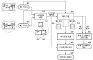
도 2는 일 실시예에 따른 디스패리티 추정 장치의 세부적인 구성을 도시한 블록도이다.2 is a block diagram illustrating a detailed configuration of an apparatus for estimating disparity according to an embodiment.
디스패리티 추정 장치(200)는 도 2에 도시된 이미지 획득부(110) 및 프로세서(120)에 더하여, 메모리(230)를 더 포함할 수 있다.The
이미지 획득부(110)는 도 1에서 설명한 바와 같은 동작을 수행할 수 있다. 예를 들어, 이미지 획득부(110)는 제1 카메라(211) 및 제2 카메라(212)를 포함할 수 있다. 제1 카메라(211) 및 제2 카메라(212)는 서로에 대해 일정 거리만큼 이격되어 배치될 수 있다. 제1 카메라(211)는 외부를 촬영하여 제1 이미지를 생성할 수 있고, 제2 카메라(212)는 제1 카메라(211)로부터 이격된 위치에서 외부를 촬영하여 제2 이미지를 생성할 수 있다. 예를 들어, 제1 카메라(211) 및 제2 카메라(212)가 수평 축을 따라 일정 거리만큼 이격되어 배치된 경우, 제1 카메라(211)는 좌 이미지(left image)를 생성할 수 있고, 제2 카메라(212)는 우 이미지(right image)를 생성할 수 있다. 다만, 이로 한정하는 것은 아니고, 예를 들어, 제1 카메라(211) 및 제2 카메라(212)가 세로축을 따라 이격되는 경우, 제1 이미지는 위쪽 이미지, 제2 이미지는 아래쪽 이미지일 수도 있다.The
프로세서(120)는 제1 이미지로부터 기준 픽셀(reference pixel)을 포함하는 제1 패치를 추출하고, 제2 이미지로부터 기준 픽셀에 대응하는 대상 픽셀을 포함하는 제2 패치를 추출할 수 있다. 예를 들어, 프로세서(120)는 제1 이미지의 적어도 일부 영역을 사각 형태로 추출하여 제1 패치를 생성할 수 있다. 또한, 프로세서(120)는 제2 이미지의 적어도 일부 영역을 사각 형태로 추출하여 제2 패치를 생성할 수 있다. 제1 패치 및 제2 패치의 크기, 및 해상도 등은 동일할 수 있다.The
본 명세서에서 패치는 전체 이미지로부터 크롭된 부분 이미지를 나타낼 수 있다. 예를 들어, 제1 패치는 제1 이미지로부터 크롭된 부분 이미지일 수 있고, 제2 패치는 제2 이미지로부터 크롭된 부분 이미지일 수 있다.In the present specification, a patch may represent a partial image cropped from the entire image. For example, the first patch may be a partial image cropped from the first image, and the second patch may be a partial image cropped from the second image.
또한, 프로세서(120)는 레지듀얼 모델(residual model)에 기초하여, 제1 패치 및 제2 패치로부터 기준 픽셀 및 대상 픽셀 간의 초기 디스패리티에 대한 레지듀얼(residual)을 추정할 수 있다.Also, the
본 명세서에서 레지듀얼 모델은 두 이미지에 대해 추정된 초기 디스패리티에 대한 오차를 출력하기 위한 모델을 나타낼 수 있다. 예를 들어, 레지듀얼 모델은 기계학습(ML, machine learning)에 적용되는 모델일 수 있다. 레지듀얼 모델은 기계학습 구조의 파라미터를 포함할 수 있다. 기계학습 구조로서 뉴럴 네트워크가 사용되는 경우 레지듀얼 모델은 뉴럴 네트워크의 각 노드 간의 연결 가중치를 포함할 수 있다.In the present specification, the residual model may represent a model for outputting an error with respect to an initial disparity estimated for two images. For example, the residual model may be a model applied to machine learning (ML). The residual model may include parameters of the machine learning structure. When a neural network is used as a machine learning structure, the residual model may include a connection weight between each node of the neural network.
일 실시예에 따르면, 레지듀얼 모델은, 주어진 기계학습 구조에 대해, 기준 이미지 쌍(reference image pair)으로부터 추출된 기준 패치 쌍(reference patch pair)로부터 해당 기준 패치들에 대응하는 기준 레지듀얼(예를 들어, 기준 이미지 쌍에 대해 추정된 초기 디스패리티와 기준 디스패리티 간의 차이)이 출력되도록 트레이닝된 기계학습 구조(예를 들어, 뉴럴 네트워크)의 파라미터를 포함할 수 있다. 기준 디스패리티는 기준 이미지 쌍 사이의 실제 디스패리티일 수 있다. 기계학습 구조를 트레이닝시키기 위한 트레이닝 데이터(training data)는 상술한 기준 패치 쌍 및 기준 레지듀얼을 포함할 수 있다. 기준 레지듀얼은 기준 패치 쌍에 대해 참(ground truth)으로 주어진 레지듀얼일 수 있다. 다만, 레지듀얼 모델의 트레이닝을 이로 한정하는 것은 아니다. 단일 손실(loss) 함수를 이용하여 레지듀얼 모델을 허위 디스패리티 검출 모델과 함께 트레이닝시키는 과정은 하기 도 5에서 설명한다.According to an embodiment, the residual model is, for a given machine learning structure, a reference residual corresponding to the corresponding reference patches from a reference patch pair extracted from a reference image pair (eg, a reference image pair). For example, it may include parameters of a machine learning structure (eg, a neural network) trained so that the difference between the initial disparity and the reference disparity estimated for the reference image pair is output. The reference disparity may be an actual disparity between the reference image pair. Training data for training the machine learning structure may include the above-described reference patch pair and reference residual. A reference residual may be a residual given as ground truth for a reference patch pair. However, training of the residual model is not limited thereto. A process of training the residual model together with the false disparity detection model using a single loss function will be described with reference to FIG. 5 below.
메모리(230)는 레지듀얼 모델을 저장할 수 있다. 또한, 메모리(230)는 레지듀얼 모델에 기초한 레지듀얼 추정을 수행하기 위해 요구되는 데이터를 임시적으로 저장할 수도 있다.The
일 실시예에 따른 디스패리티 추정 장치(200)는 스테레오 카메라(예를 들어, 제1 카메라(211) 및 제2 카메라(212))로부터 획득한 제1 이미지 및 제2 이미지로부터 초기 디스패리티를 산출하고, 초기 디스패리티에 대한 레지듀얼을 추정 및 반영함으로써, 높은 정확도(high accuracy)를 가지는 최종 디스패리티를 결정할 수 있다. 디스패리티 추정 장치(200)는 레지듀얼 모델을 이용하여 레지듀얼을 추정함으로써, 영상의 특징을 고려하지 않고 손실 곡선(loss curve)에 피팅(fitting)하는 방법보다 더 정확한 최종 디스패리티를 결정할 수 있다.The
도 3은 일 실시예에 따른 디스패리티 추정 과정을 설명하는 도면이다.3 is a diagram illustrating a disparity estimation process according to an embodiment.
우선, 디스패리티 추정 장치의 프로세서는 이미지 획득부로부터 상술한 바와 같이 제1 이미지(301) 및 제2 이미지(302)를 수신할 수 있다. 본 명세서에서 편의상 제1 이미지(301)는 좌 이미지, 제2 이미지(302)는 우 이미지인 것으로 설명하나, 이로 한정하는 것은 아니다.First, the processor of the disparity estimation apparatus may receive the
프로세서는 제1 이미지(301) 및 제2 이미지(302)로부터 초기 디스패리티를 추정할 수 있다. 제1 이미지(301) 및 제2 이미지(302) 간의 초기 디스패리티 추정은 스테레오 매칭(stereo matching)(310)이라고 나타낼 수 있다. 예를 들어, 스테레오 매칭은 대응점을 찾기 위해 픽셀의 세기(intensity), 색상(color) 등의 영상 정보를 비교하거나, 픽셀을 중심으로 한 패치의 세기, 색상 등의 영상 정보 등을 비교하는 동작을 나타낼 수 있다. 일 실시예에 따르면 프로세서는 MBM(multi-block-matching stereo) 방식으로 제1 이미지(301) 및 제2 이미지(302) 간의 초기 디스패리티를 추정할 수 있다. 예를 들어, 프로세서는 제1 이미지(301)의 기준 픽셀 및 제2 이미지(302)의 대상 픽셀 간의 초기 디스패리티를 추정할 수 있다.The processor may estimate an initial disparity from the
우선, 프로세서는 제1 이미지(301)의 기준 픽셀을 포함하는 제1 패치(311)와 제2 이미지(302)의 검색 범위(312)를 비교함으로써 대상 픽셀을 포함하는 제2 패치(313)를 결정하고, 제1 패치(311) 및 제2 패치(313) 간의 위치 차이에 대응하는 초기 디스패리티를 추정할 수 있다. 여기서, 프로세서는 제1 이미지(301)에 나타나는 적어도 하나의 객체에 대응하는 픽셀에 대하여 초기 디스패리티를 추정할 수 있다. 예를 들어, 프로세서는 제1 이미지(301)로부터 특징점(feature point)을 추출할 수 있다. 특징점은 제1 이미지(301)의 특징을 나타내는 지점으로서, 제1 이미지(301)에 나타나는 객체(object)(예를 들어, 도 3에 도시된 차량)의 일부에 대응하는 픽셀일 수 있다. 프로세서는 제1 이미지(301)로부터 특징점에 대응하는 픽셀을 기준 픽셀로 결정할 수 있다. 예를 들어, 도 3에서 프로세서는 제1 이미지(301)에서 검출된 차량에 대응하는 객체 영역의 중심점을 특징점으로 추출할 수 있다. 다만, 이로 한정하는 것은 아니고, 프로세서는 제1 이미지(301)에서 객체 영역의 적어도 일부 지점 또는 모든 지점을 특징점으로 추출할 수도 있다.First, the processor determines the
그리고 프로세서는, 제2 이미지(302)에서 검색 범위(312)를 결정할 수 있다. 일 실시예에 따르면 프로세서는 제1 이미지(301)의 기준 픽셀을 포함하는 제1 패치(311)에 기초하여 검색 범위(312)를 결정할 수 있다. 예를 들어, 프로세서는 제2 이미지(302)로부터 제1 이미지(301)의 제1 패치(311)와 동일한 높이의 영역을 검색 범위(312)로 결정할 수 있다.And the processor may determine the
이어서, 프로세서는 검색 범위(312)에 포함된 후보 픽셀들의 각각에 대응하는 후보 패치마다 기준 픽셀을 포함하는 기준 패치를 비교할 수 있다. 예를 들어, 후보 픽셀은 제2 이미지(302)의 검색 범위(312) 내에서, 기준 픽셀과 동일한 높이를 가지는 픽셀일 수 있다. 도 3에서는 제2 이미지(302) 내에서 기준 픽셀과 동일한 높이를 가지는 일부 픽셀이 후보 픽셀로 결정되었으나, 기준 픽셀과 동일한 높이를 가지는 모든 픽셀이 후보 픽셀로 결정될 수도 있다. 후보 패치는 검색 범위(312)로부터 후보 픽셀을 중심 지점으로 크롭(crop)된 이미지를 나타낼 수 있다. 여기서, 기준 패치와 후보 패치의 크기 및 해상도는 동일할 수 있다. 본 명세서에서 기준 패치는 스테레오 매칭(310)의 기준이 되는 패치를 나타낼 수 있고, 후보 패치는 기준 패치와의 비교를 위해 선택된 패치를 나타낼 수 있다.Then, the processor may compare the reference patch including the reference pixel for each candidate patch corresponding to each of the candidate pixels included in the
그리고 프로세서는 후보 패치 및 기준 패치 간의 비교 결과에 기초하여, 제2 이미지(302)로부터 대상 픽셀을 결정할 수 있다. 예를 들어, 프로세서는 각 후보 패치와 기준 패치를 비교하여 유사도(similarity level)를 산출할 수 있다. 프로세서는 검색 범위(312) 내에서 가장 높은 유사도를 가지는 후보 패치에 대응하는 픽셀(예를 들어, 해당 후보 패치의 중심 지점)을 대상 픽셀로 결정할 수 있다.In addition, the processor may determine a target pixel from the
이후, 프로세서는 제1 이미지(301) 및 제2 이미지(302)의 각각으로부터 패치를 크롭(320)할 수 있다. 예를 들어, 프로세서는 제1 이미지(301)로부터 기준 픽셀을 포함하는 제1 패치(311)를 추출할 수 있다. 프로세서는 제2 이미지(302)로부터 대상 픽셀을 포함하는 제2 패치(313)를 추출할 수 있다.The processor may then crop 320 a patch from each of the
프로세서는 레지듀얼 모델(330)을 이용하여, 제1 패치(311) 및 제2 패치(313)로부터 레지듀얼을 추정할 수 있다. 프로세서는 기준 패치 쌍(reference patch pair)으로부터 기준 레지듀얼(reference residual)을 출력하도록 트레이닝된 레지듀얼 모델(330)에 제1 패치(311) 및 제2 패치(313)를 입력할 수 있다. 프로세서는 제1 패치(311) 및 제2 패치(313)를 특징 데이터 형태로 레지듀얼 모델(330)에 입력함으로써, 레지듀얼 모델(330)에 기초하여, 특징 데이터로부터 레지듀얼을 추정할 수 있다. 프로세서는 예를 들어, 특징 모델에 기초하여, 제1 패치 및 제2 패치로부터 특징 데이터를 산출할 수 있다. 특징 모델은 하기 도 5에서 설명한다.The processor may estimate a residual from the
프로세서는 제1 패치(311) 및 제2 패치(313)를 해당 레지듀얼 모델(330)에 입력함으로써 서브 픽셀 단위의 레지듀얼을 출력할 수 있다. 서브 픽셀 단위는 하기 도 9에서 설명한다.The processor may output the residual in units of sub-pixels by inputting the
프로세서는 레지듀얼을 이용하여 초기 디스패리티를 보정(340)할 수 있다. 프로세서는 추정된 레지듀얼을 초기 디스패리티에 반영함으로써, 최종 디스패리티를 결정할 수 있다. 예를 들어, 프로세서는 초기 디스패리티에 레지듀얼을 가산(add)함으로써, 최종 디스패리티(309)를 산출할 수 있다.The processor may correct 340 the initial disparity using the residual. The processor may determine the final disparity by reflecting the estimated residual in the initial disparity. For example, the processor may calculate the
도 4는 도 3에 도시된 과정에 더하여, 허위 디스패리티 정보를 산출하는 과정이 추가된 도면이다.FIG. 4 is a diagram in which a process of calculating false disparity information is added in addition to the process shown in FIG. 3 .
프로세서는 도 3에 도시된 바와 같이 최종 디스패리티(309)를 산출하는 한편, 제1 패치(311) 및 제2 패치(313)를 이용하여 허위 디스패리티 정보(408)를 추정할 수 있다.The processor may calculate the
일 실시예에 따르면, 프로세서는 허위 디스패리티 검출 모델(false disparity detection model)(450)에 기초하여, 제1 패치(311) 및 제2 패치(313)로부터 초기 디스패리티의 허위 디스패리티 정보(false disparity information)(408)를 추정할 수 있다. 허위 디스패리티 정보(408)는 초기 디스패리티의 거짓과 관련된 정보로서, 예를 들어, 초기 디스패리티가 거짓일 확률에 관한 정보일 수 있다.According to an embodiment, the processor is configured to generate false disparity information of the initial disparity from the
허위 디스패리티 검출 모델(450)은 기준 패치 쌍(patch pair)로부터 기준 허위 디스패리티 정보(408)가 출력되도록 트레이닝된 모델일 수 있다. 기준 허위 디스패리티 정보(408)는 미리 생성된 정보로서, 기준 패치 쌍으로부터 산출된 초기 디스패리티가 거짓을 나타냈던 확률을 나타낼 수 있다.The false
프로세서는 추정된 허위 디스패리티 정보(408)에 기초하여, 초기 디스패리티가 거짓으로 판단된 경우에 응답하여, 초기 디스패리티를 배제(exclude)할 수 있다.The processor may exclude the initial disparity in response to the case that the initial disparity is determined to be false based on the estimated
예를 들어, 프로세서는 추정된 허위 디스패리티 정보(408)가 임계 허위 정도(threshold false level)을 초과하는 경우에 응답하여, 초기 디스패리티를 배제할 수 있다. 임계 허위 정도는 거짓의 기준이 되는 정도(level)로서, 예를 들어, 초기 디스패리티가 거짓인 지 여부를 결정하는 기준이 되는 확률일 수 있다.For example, the processor may rule out the initial disparity in response if the estimated
다른 예를 들어, 프로세서는 추정된 허위 디스패리티 정보(408)가 임계 허위 정도 이하인 경우에 응답하여, 초기 디스패리티에 기초한 레지듀얼 추정 동작을 계속할 수 있다.For another example, the processor may continue the residual estimation operation based on the initial disparity in response to the case where the estimated
도 5는 일 실시예에 따른 레지듀얼 모델 및 허위 디스패리티 검출 모델의 트레이닝 과정을 설명하는 도면이다.5 is a diagram illustrating a training process of a residual model and a false disparity detection model according to an embodiment.
일 실시예에 따르면 레지듀얼 모델(534) 및 허위 디스패리티 검출 모델(550)은 특징 모델들(531, 532)(예를 들어, 특징 추출 네트워크)을 공유하도록 다음과 같은 기계학습 구조로 설계될 수 있다.According to an embodiment, the
우선, 프로세서는 입력되는 이미지 쌍(image pair)로부터 초기 디스패리티(Dinit)를 추정(510)하고, 초기 디스패리티(Dinit)에 기초하여 각 이미지로부터 패치를 크롭(520)할 수 있다.First, the processor may estimate 510 an initial disparity Dinit from an input image pair, and crop 520 a patch from each image based on the initial disparity Dinit .
프로세서는 크롭된 패치들의 각각으로부터 특징 모델들(531, 532)에 기초하여 특징 데이터를 추출할 수 있고, 추출된 특징 데이터들을 통합 모델(533)(예를 들어, concatenate network)에 기초하여 통합하여 통합 데이터(concatenated data)를 생성할 수 있다. 예를 들어, 특징 모델들(531, 532)은 패치로부터 저레벨 특징(low-level feature)을 추출하도록 트레이닝될 수 있다. 저레벨 특징은 예를 들어, 점, 선, 텍스쳐(texture), 색상(color) 등의 조합으로 표현되는 영상 특징 데이터를 나타낼 수 있다.The processor may extract feature data based on the feature models 531 and 532 from each of the cropped patches, and integrate the extracted feature data based on the unified model 533 (eg, a concatenate network). Concatenated data can be created. For example, feature models 531 and 532 may be trained to extract a low-level feature from a patch. The low-level feature may represent image feature data expressed by, for example, a combination of points, lines, textures, colors, and the like.
프로세서는 상술한 바와 같이 추출된 통합 데이터를 레지듀얼 모델(534) 및 허위 디스패리티 검출 모델(550)에 입력하여 각각 레지듀얼(
트레이닝 장치는 상술한 바와 같이 구성된 기계학습 구조를 트레이닝시킬 수 있다. 예를 들어, 트레이닝 장치는 도 5에 도시된 기계학습 구조에 대해, 제1 기준 이미지(501) 및 제2 기준 이미지(502)(이하, 기준 이미지 쌍)으로부터 해당 기준 이미지들(501, 502)에 대응하는 기준 디스패리티(DGT)가 출력되도록 트레이닝시킬 수 있다. 트레이닝 장치는 특징 모델들(531, 532), 레지듀얼 모델(534), 및 허위 디스패리티 검출 모델(550)을 하나의 손실(509)(loss)로 트레이닝시킬 수 있다. 예를 들어, 제1 기준 이미지(501)에서 n개의 특징점이 추출된 경우, 트레이닝 장치는 손실(509) L을 하기 수학식 1 및 수학식 2와 같이 나타낼 수 있다. 여기서, n은 1이상의 정수일 수 있다.The training apparatus may train the machine learning structure constructed as described above. For example, for the machine learning structure shown in FIG. 5 , the training apparatus may perform corresponding
[수학식 1][Equation 1]

[수학식 2][Equation 2]

여기서, PiEST=(1-Prob(LFID))는 i번째 특징점에 대해 초기 디스패리티(Dinit)가 참(true)일 확률을 나타낼 수 있다. 여기서, i는 1이상 n이하의 정수일 수 있다. CE는 크로스 엔트로피 손실(509)(cross-entropy loss)을 나타낼 수 있다.

초기 디스패리티(Dinit)가 참일 확률이 높을 때, 트레이닝 장치는 상술한 수학식 1의

한편, 트레이닝 장치는 크로스 엔트로피에 대응하는 수학식 1의
또한, 트레이닝 장치는 두 손실(509), 예를 들어,


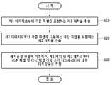
도 6은 일 실시예에 따른 디스패리티 추정 방법을 도시한 흐름도이다.6 is a flowchart illustrating a disparity estimation method according to an embodiment.
우선, 단계(610)에서 프로세서는 제1 이미지로부터 기준 픽셀을 포함하는 제1 패치를 추출할 수 있다. 일 실시예에 따르면, 프로세서는 제1 이미지로부터 특징점을 추출할 수 있고, 특징점에 대응하는 픽셀을 기준 픽셀로 결정할 수 있다. 특징점은 예를 들어, 제1 이미지에 나타나는 객체에 대응하는 영역의 적어도 일부일 수 있다.First, in
그리고 단계(620)에서 프로세서는 제2 이미지로부터 기준 픽셀에 대응하는 대상 픽셀을 포함하는 제2 패치를 추출할 수 있다. 일 실시예에 따르면 프로세서는 스테레오 매칭을 통해 제1 이미지의 기준 픽셀에 대응하는 제2 이미지의 대상 픽셀을 결정할 수 있다. 또한, 프로세서는 대상 픽셀에 기초하여 제2 패치를 추출할 수 있다. 예를 들어, 프로세서는 대상 픽셀을 중심 지점으로 하여 제2 패치를 추출할 수 있다.In
이어서 단계(630)에서 프로세서는 레지듀얼 모델에 기초하여, 제1 패치 및 제2 패치로부터 기준 픽셀 및 대상 픽셀 간의 초기 디스패리티에 대한 레지듀얼을 추정할 수 있다. 예를 들어, 프로세서는 제1 패치 및 제2 패치로부터 특징 데이터를 추출할 수 있고, 추출된 특징 데이터를 레지듀얼 모델에 입력함으로써 초기 디스패리티에 대한 레지듀얼을 출력할 수 있다.Subsequently, in
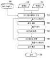
도 7은 일 실시예에 따라 보정된 디스패리티를 이용한 깊이 계산을 설명하는 도면이다.7 is a diagram for describing depth calculation using corrected disparity according to an exemplary embodiment.
도 7에서는 제1 이미지를 좌영상(701), 제2 이미지를 우영상(702)으로 설명하였으나, 이로 한정하는 것은 아니다. 디스패리티 추정 장치에 포함된 카메라의 배열에 따라 설계가 변경될 수 있다.In FIG. 7 , the first image is described as a
우선, 단계(710)에서 디스패리티 추정 장치는 초기 디스패리티를 추정할 수 있다. 예를 들어, 디스패리티 추정 장치는 스테레오 카메라로 입력된 좌영상 및 우영상(702)을 이용해 스테레오 매칭을 수행할 수 있다. 이 때, 디스패리티 추정 장치는 데이터베이스(705)로부터 레지듀얼 모델을 로딩할 수 있다.First, in
그리고 단계(720)에서 디스패리티 추정 장치는 초기 디스패리티에 기초하여 좌영상(701)으로부터 좌패치 및 우영상(702)으로부터 우패치를 크롭할 수 있다.In
이어서 단계(730)에서 디스패리티 추정 장치는 레지듀얼 모델에 기초하여 좌패치 및 우패치로부터 서브 픽셀 단위로 레지듀얼을 추정할 수 있다. 레지듀얼 모델은 예를 들어, 딥 뉴럴 네트워크(deep neural network) 구조일 수 있다.Subsequently, in
그리고 단계(740)에서 디스패리티 추정 장치는 레지듀얼을 이용하여 초기 디스패리티를 보정할 수 있다. 예를 들어, 디스패리티 추정 장치는 레지듀얼을 초기 디스패리티에 가산하여 최종 디스패리티를 산출할 수 있다.And in
이어서 단계(750)에서 디스패리티 추정 장치의 프로세서는, 최종 디스패리티를 이용하여, 제1 이미지 및 제2 이미지의 각 픽셀에 대응하는 깊이(709)를 계산할 수 있다.Subsequently, in
일 실시예에 따르면 디스패리티 추정 장치는 좌영상(701)에서 특징점으로 추출된 모든 픽셀들에 대하여, 상술한 단계들(710 내지 750)을 반복할 수 있다. 디스패리티 추정 장치는 좌영상(701)에서 추출된 모든 픽셀들에 대한 깊이(709)를 계산할 수 있다. 계산된 깊이(709)는 좌영상(701) 및 우영상(702)에 나타난 객체를 3D 형태(3D shape)로 모델링하는데 사용될 수 있다.According to an embodiment, the disparity estimating apparatus may repeat the above-described
도 8은 도 7에 설명된 깊이 계산에 허위 디스패리티 검출이 적용된 것을 설명하는 도면이다.FIG. 8 is a view for explaining that false disparity detection is applied to the depth calculation described in FIG. 7 .
초기 디스패리티가 실제 디스패티리(ground truth disparity)와 유사한 경우, 도 7에서 디스패리티 추정 장치는 최종 디스패리티 및 깊이를 정확하게 산출할 수 있다. 다만, 초기 디스패리티가 실제 디스패리티와 큰 차이를 나타내는 경우, 레지듀얼 추정의 정확도가 감소될 수 있다. 이러한 정확도 감소를 방지하기 위해, 디스패리티 추정 장치는 초기 디스패리티와 실제 디스패리티 간의 차이를 고려하여, 초기 디스패리티에 대한 허위 디스패리티 정보(808)를 산출할 수 있다.When the initial disparity is similar to the actual disparity (ground truth disparity), the disparity estimating apparatus in FIG. 7 may accurately calculate the final disparity and depth. However, when the initial disparity has a large difference from the actual disparity, the accuracy of residual estimation may be reduced. To prevent such a decrease in accuracy, the disparity estimating apparatus may calculate
예를 들어, 단계(860)에서 디스패리티 추정 장치는 허위 디스패리티 검출 모델에 기초하여, 좌 패치 및 우 패치로부터 허위 디스패리티 정보(808)를 산출할 수 있다. 허위 디스패리티 검출 모델은 예를 들어, 뉴럴 네트워크 구조일 수 있다. 허위 디스패리티 정보(808)는 초기 디스패리티가 거짓일 확률을 나타내므로, 계산된 깊이(709)의 신뢰도(reliability level)에 대응할 수 있다. 더 나아가, 디스패리티 추정 장치는 허위 디스패리티 정보(808)가 임계 허위 정도를 초과하는 경우에 응답하여, 추정된 레지듀얼을 깊이 계산으로부터 배제할 수도 있다. 이 때, 좌영상(701) 및 우영상(702)이 연속된 프레임으로 구성되는 경우, 프로세서는 깊이 계산을 다음 프레임으로 유예할 수 있다.For example, in
도 9는 일 실시예에 따른 디스패리티 추정 장치가 서브 픽셀 단위로 디스패리티를 추정하는 것을 설명하는 도면이다.FIG. 9 is a diagram for explaining that a disparity estimating apparatus according to an embodiment estimates disparity in units of sub-pixels.
디스패리티 추정 장치의 프로세서는, 초기 디스패리티를 정수 픽셀(integer pixel) 단위로 추정하고, 레지듀얼을 서브 픽셀(sub pixel) 단위로 추정할 수 있다. 본 명세서에서 정수 픽셀 단위는 픽셀 하나에 의해 정의되는 단위를 나타낼 수 있고, 서브 픽셀 단위는 픽셀보다 작은 단위로서, 예를 들어, 임의의 거리가 픽셀 하나에 대해 가지는 비율을 지시하는 실수일 수 있다.The processor of the disparity estimation apparatus may estimate the initial disparity in units of integer pixels and estimate the residual in units of sub-pixels. In this specification, the integer pixel unit may represent a unit defined by one pixel, and the sub-pixel unit may be a unit smaller than a pixel, for example, may be a real number indicating a ratio of an arbitrary distance to one pixel. .
예를 들어, 도 9는 설명의 편의를 위해 제1 이미지(901) 및 제2 이미지(902)를 각각 8 x 8개의 픽셀로 구성되는 것으로 도시하였다. 제1 이미지(901) 및 제2 이미지(902)에는 객체(951, 952)가 나타날 수 있다. 프로세서는 스테레오 매칭(910)에 의해 제1 이미지(901)의 기준 지점(911)과 제2 이미지(902) 간의 대상 지점(921) 간의 초기 디스패리티를 추정할 수 있다. 도 9에서 기준 지점(911) 및 대상 지점(921) 간의 초기 디스패리티는 정수 픽셀 단위인 1일 수 있다. 도 9에서 초기 디스패리티에 대해 추정된 레지듀얼(920)은 -0.8일 수 있다. 프로세서는 초기 디스패리티에 레지듀얼(920)을 보정함으로써, 최종 디스패리티를 0.2로 결정할 수 있다. 따라서, 디스패리치 추정 장치는 기준 지점(911)에 대응하는 제2 이미지(902)의 최종 지점(922)을 결정할 수 있다. 위에서 설명한 초기 디스패리티, 최종 디스패리티, 및 레지듀얼(920)의 값은 순전히 예시적인 값이다.For example, FIG. 9 illustrates that the
일 실시예에 따른 디스패리티 추정 장치는 스테레오 카메라를 이용하여 깊이를 측정하기 위해, 좌영상 및 우영상의 대응점을 찾는 스테레오 매칭을 수행할 수 있다. 프로세서는 스테레오 매칭을 통해 정수 픽셀 단위로 초기 디스패리티를 추정할 수 있다. 다만, 정수 픽셀 단위로 추정된 초기 디스패리티를 이용하여 깊이를 산출할 경우, 깊이 해상도(depth resolution)는 스테레오 카메라의 픽셀의 물리적 크기에 의존할 수 있다. 디스패리티 추정 장치는 레지듀얼 모델을 이용하여 서브 픽셀 단위로 레지듀얼을 추정함으로써, 보다 정밀하게 최종 디스패리티 및 깊이를 추정할 수 있다. 상술한 바와 같이 정밀하게 추정된 깊이는 보다 정밀한 3D 형태를 모델링하는데 사용될 수 있다.The apparatus for estimating disparity according to an embodiment may perform stereo matching to find a correspondence point between a left image and a right image in order to measure depth using a stereo camera. The processor may estimate the initial disparity in units of integer pixels through stereo matching. However, when the depth is calculated using the initial disparity estimated in units of integer pixels, the depth resolution may depend on the physical size of the pixel of the stereo camera. The disparity estimating apparatus may estimate the final disparity and depth more precisely by estimating the residual in units of sub-pixels using the residual model. As described above, the precisely estimated depth can be used to model a more precise 3D shape.
일 실시예에 따른 디스패리티 추정 장치는 스테레오 이미지의 각 픽셀에 대한 깊이를 효율적으로 정밀하게 추정할 수 있다. 이러한 디스패리티 추정 장치는 차량용 깊이 센서(depth sensor) 및 모바일 깊이 센서 등으로 구현될 수 있다.The disparity estimating apparatus according to an embodiment may efficiently and precisely estimate the depth of each pixel of the stereo image. Such a disparity estimation apparatus may be implemented as a vehicle depth sensor, a mobile depth sensor, or the like.
이상에서 설명된 장치는 하드웨어 구성요소, 소프트웨어 구성요소, 및/또는 하드웨어 구성요소 및 소프트웨어 구성요소의 조합으로 구현될 수 있다. 예를 들어, 실시예들에서 설명된 장치 및 구성요소는, 예를 들어, 프로세서, 콘트롤러, ALU(arithmetic logic unit), 디지털 신호 프로세서(digital signal processor), 마이크로컴퓨터, FPA(field programmable array), PLU(programmable logic unit), 마이크로프로세서, 또는 명령(instruction)을 실행하고 응답할 수 있는 다른 어떠한 장치와 같이, 하나 이상의 범용 컴퓨터 또는 특수 목적 컴퓨터를 이용하여 구현될 수 있다. 처리 장치는 운영 체제(OS) 및 운영 체제 상에서 수행되는 하나 이상의 소프트웨어 애플리케이션을 수행할 수 있다. 또한, 처리 장치는 소프트웨어의 실행에 응답하여, 데이터를 접근, 저장, 조작, 처리 및 생성할 수도 있다. 이해의 편의를 위하여, 처리 장치는 하나가 사용되는 것으로 설명된 경우도 있지만, 해당 기술분야에서 통상의 지식을 가진 자는, 처리 장치가 복수 개의 처리 요소(processing element) 및/또는 복수 유형의 처리 요소를 포함할 수 있음을 알 수 있다. 예를 들어, 처리 장치는 복수 개의 프로세서 또는 하나의 프로세서 및 하나의 콘트롤러를 포함할 수 있다. 또한, 병렬 프로세서(parallel processor)와 같은, 다른 처리 구성(processing configuration)도 가능하다.The device described above may be implemented as a hardware component, a software component, and/or a combination of the hardware component and the software component. For example, devices and components described in the embodiments may include, for example, a processor, a controller, an arithmetic logic unit (ALU), a digital signal processor, a microcomputer, a field programmable array (FPA), It may be implemented using one or more general purpose or special purpose computers, such as a programmable logic unit (PLU), microprocessor, or any other device capable of executing and responding to instructions. The processing device may execute an operating system (OS) and one or more software applications running on the operating system. The processing device may also access, store, manipulate, process, and generate data in response to execution of the software. For convenience of understanding, although one processing device is sometimes described as being used, one of ordinary skill in the art will recognize that the processing device includes a plurality of processing elements and/or a plurality of types of processing elements. It can be seen that may include For example, the processing device may include a plurality of processors or one processor and one controller. Other processing configurations are also possible, such as parallel processors.
소프트웨어는 컴퓨터 프로그램(computer program), 코드(code), 명령(instruction), 또는 이들 중 하나 이상의 조합을 포함할 수 있으며, 원하는 대로 동작하도록 처리 장치를 구성하거나 독립적으로 또는 결합적으로(collectively) 처리 장치를 명령할 수 있다. 소프트웨어 및/또는 데이터는, 처리 장치에 의하여 해석되거나 처리 장치에 명령 또는 데이터를 제공하기 위하여, 어떤 유형의 기계, 구성요소(component), 물리적 장치, 가상 장치(virtual equipment), 컴퓨터 저장 매체 또는 장치, 또는 전송되는 신호 파(signal wave)에 영구적으로, 또는 일시적으로 구체화(embody)될 수 있다. 소프트웨어는 네트워크로 연결된 컴퓨터 시스템 상에 분산되어서, 분산된 방법으로 저장되거나 실행될 수도 있다. 소프트웨어 및 데이터는 하나 이상의 컴퓨터 판독 가능 기록 매체에 저장될 수 있다.The software may comprise a computer program, code, instructions, or a combination of one or more thereof, which configures a processing device to operate as desired or is independently or collectively processed You can command the device. The software and/or data may be any kind of machine, component, physical device, virtual equipment, computer storage medium or device, to be interpreted by or to provide instructions or data to the processing device. , or may be permanently or temporarily embody in a transmitted signal wave. The software may be distributed over networked computer systems and stored or executed in a distributed manner. Software and data may be stored in one or more computer-readable recording media.
실시예에 따른 방법은 다양한 컴퓨터 수단을 통하여 수행될 수 있는 프로그램 명령 형태로 구현되어 컴퓨터 판독 가능 매체에 기록될 수 있다. 컴퓨터 판독 가능 매체는 프로그램 명령, 데이터 파일, 데이터 구조 등을 단독으로 또는 조합하여 포함할 수 있다. 매체에 기록되는 프로그램 명령은 실시예를 위하여 특별히 설계되고 구성된 것들이거나 컴퓨터 소프트웨어 당업자에게 공지되어 사용 가능한 것일 수도 있다. 컴퓨터 판독 가능 기록 매체의 예에는 하드 디스크, 플로피 디스크 및 자기 테이프와 같은 자기 매체(magnetic media), CD-ROM, DVD와 같은 광기록 매체(optical media), 플롭티컬 디스크(floptical disk)와 같은 자기-광 매체(magneto-optical media), 및 롬(ROM), 램(RAM), 플래시 메모리 등과 같은 프로그램 명령을 저장하고 수행하도록 특별히 구성된 하드웨어 장치가 포함된다. 프로그램 명령의 예에는 컴파일러에 의해 만들어지는 것과 같은 기계어 코드뿐만 아니라 인터프리터 등을 사용해서 컴퓨터에 의해서 실행될 수 있는 고급 언어 코드를 포함한다. 상기된 하드웨어 장치는 실시예의 동작을 수행하기 위해 하나 이상의 소프트웨어 모듈로서 작동하도록 구성될 수 있으며, 그 역도 마찬가지이다.The method according to the embodiment may be implemented in the form of program instructions that can be executed through various computer means and recorded in a computer-readable medium. The computer-readable medium may include program instructions, data files, data structures, and the like, alone or in combination. The program instructions recorded on the medium may be specially designed and configured for the embodiment, or may be known and available to those skilled in the art of computer software. Examples of the computer-readable recording medium include magnetic media such as hard disks, floppy disks and magnetic tapes, optical media such as CD-ROMs and DVDs, and magnetic such as floppy disks. - includes magneto-optical media, and hardware devices specially configured to store and execute program instructions, such as ROM, RAM, flash memory, and the like. Examples of program instructions include not only machine language codes such as those generated by a compiler, but also high-level language codes that can be executed by a computer using an interpreter or the like. The hardware devices described above may be configured to operate as one or more software modules to perform the operations of the embodiments, and vice versa.
이상과 같이 실시예들이 비록 한정된 도면에 의해 설명되었으나, 해당 기술분야에서 통상의 지식을 가진 자라면 상기를 기초로 다양한 기술적 수정 및 변형을 적용할 수 있다. 예를 들어, 설명된 기술들이 설명된 방법과 다른 순서로 수행되거나, 및/또는 설명된 시스템, 구조, 장치, 회로 등의 구성요소들이 설명된 방법과 다른 형태로 결합 또는 조합되거나, 다른 구성요소 또는 균등물에 의하여 대치되거나 치환되더라도 적절한 결과가 달성될 수 있다. As described above, although the embodiments have been described with reference to the limited drawings, those skilled in the art may apply various technical modifications and variations based on the above. For example, the described techniques are performed in a different order than the described method, and/or the described components of the system, structure, apparatus, circuit, etc. are combined or combined in a different form than the described method, or other components Or substituted or substituted by equivalents may achieve an appropriate result.
그러므로, 다른 구현들, 다른 실시예들 및 특허청구범위와 균등한 것들도 후술하는 특허청구범위의 범위에 속한다.Therefore, other implementations, other embodiments, and equivalents to the claims are also within the scope of the following claims.
100: 디스패리티 추정 장치
110: 이미지 획득부
120: 프로세서100: disparity estimation device
110: image acquisition unit
120: processor
Claims (20)
Translated fromKorean제1 이미지로부터 기준 픽셀(reference pixel)을 포함하는 제1 패치를 추출하는 단계;
제2 이미지로부터 상기 기준 픽셀에 대응하는 대상 픽셀을 포함하는 제2 패치를 추출하는 단계;
상기 제1 이미지의 상기 기준 픽셀 및 상기 제2 이미지의 상기 대상 픽셀 간의 초기 디스패리티를 추정하는 단계; 및
레지듀얼 모델(residual model)에 기초하여, 상기 제1 패치 및 상기 제2 패치로부터 상기 기준 픽셀 및 상기 대상 픽셀 간의 상기 초기 디스패리티에 대한 레지듀얼(residual)을 추정하는 단계
를 포함하고,
상기 초기 디스패리티를 정수 픽셀(integer pixel) 단위로 추정하는 단계
를 더 포함하며,
상기 레지듀얼을 추정하는 단계는,
상기 레지듀얼을 정수 픽셀 단위 보다 작은 서브 픽셀(sub pixel) 단위로 추정하는 단계
를 포함하는 디스패리티 추정 방법.A disparity estimation method performed by a processor, comprising:
extracting a first patch comprising a reference pixel from the first image;
extracting a second patch including a target pixel corresponding to the reference pixel from a second image;
estimating an initial disparity between the reference pixel of the first image and the target pixel of the second image; and
estimating a residual for the initial disparity between the reference pixel and the target pixel from the first patch and the second patch based on a residual model;
including,
estimating the initial disparity in units of integer pixels;
further comprising,
The step of estimating the residual comprises:
estimating the residual in sub-pixel units smaller than integer pixel units;
Disparity estimation method comprising a.
상기 추정된 레지듀얼을 상기 초기 디스패리티에 보정함으로써, 최종 디스패리티를 결정하는 단계
를 더 포함하는 디스패리티 추정 방법.According to claim 1,
determining a final disparity by correcting the estimated residual to the initial disparity;
Disparity estimation method further comprising a.
상기 최종 디스패리티를 이용하여, 상기 제1 이미지 및 상기 제2 이미지의 각 픽셀에 대응하는 깊이를 계산하는 단계
를 더 포함하는 디스패리티 추정 방법.3. The method of claim 2,
calculating a depth corresponding to each pixel of the first image and the second image by using the final disparity;
Disparity estimation method further comprising a.
상기 초기 디스패리티를 추정하는 단계는,
상기 제2 이미지에서 검색 범위를 결정하는 단계;
상기 검색 범위에 포함된 픽셀들의 각각에 대응하는 후보 패치마다 상기 기준 픽셀을 포함하는 기준 패치를 비교하는 단계; 및
상기 후보 패치 및 상기 기준 패치 간의 비교 결과에 기초하여, 상기 제2 이미지로부터 상기 대상 픽셀을 결정하는 단계
를 포함하는 디스패리티 추정 방법.According to claim 1,
The step of estimating the initial disparity comprises:
determining a search range in the second image;
comparing a reference patch including the reference pixel for each candidate patch corresponding to each of the pixels included in the search range; and
determining the target pixel from the second image based on a comparison result between the candidate patch and the reference patch;
Disparity estimation method comprising a.
상기 레지듀얼을 추정하는 단계는,
특징 모델에 기초하여, 상기 제1 패치 및 상기 제2 패치로부터 특징 데이터를 산출하는 단계; 및
상기 레지듀얼 모델에 기초하여, 상기 특징 데이터로부터 상기 레지듀얼을 추정하는 단계
를 포함하는 디스패리티 추정 방법.According to claim 1,
The step of estimating the residual comprises:
calculating feature data from the first patch and the second patch based on a feature model; and
estimating the residual from the feature data based on the residual model
Disparity estimation method comprising a.
허위 디스패리티 검출 모델(false disparity detection model)에 기초하여, 상기 제1 패치 및 상기 제2 패치로부터 상기 초기 디스패리티의 허위 디스패리티 정보(false disparity information)를 추정하는 단계
를 더 포함하는 디스패리티 추정 방법.According to claim 1,
estimating false disparity information of the initial disparity from the first patch and the second patch based on a false disparity detection model;
Disparity estimation method further comprising a.
상기 추정된 허위 디스패리티 정보에 기초하여, 상기 초기 디스패리티가 거짓(false)인 것으로 판단된 경우에 응답하여, 상기 초기 디스패리티를 배제(exclude)하는 단계
를 더 포함하는 디스패리티 추정 방법.8. The method of claim 7,
excluding the initial disparity in response when it is determined that the initial disparity is false based on the estimated false disparity information;
Disparity estimation method further comprising a.
상기 제1 패치를 추출하는 단계는,
상기 제1 이미지로부터 특징점(feature point)을 추출하는 단계;
상기 제1 이미지로부터 상기 특징점에 대응하는 픽셀을 상기 기준 픽셀로 결정하는 단계
를 포함하는 디스패리티 추정 방법.According to claim 1,
The step of extracting the first patch,
extracting a feature point from the first image;
determining a pixel corresponding to the feature point from the first image as the reference pixel
Disparity estimation method comprising a.
제1 이미지 및 제2 이미지를 획득하는 이미지 획득부; 및
상기 제1 이미지로부터 기준 픽셀(reference pixel)을 포함하는 제1 패치를 추출하고, 제2 이미지로부터 상기 기준 픽셀에 대응하는 대상 픽셀을 포함하는 제2 패치를 추출하며, 상기 제1 이미지의 상기 기준 픽셀 및 상기 제2 이미지의 상기 대상 픽셀 간의 초기 디스패리티를 추정하고, 레지듀얼 모델(residual model)에 기초하여, 상기 제1 패치 및 상기 제2 패치로부터 상기 기준 픽셀 및 상기 대상 픽셀 간의 상기 초기 디스패리티에 대한 레지듀얼(residual)을 추정하고, 상기 초기 디스패리티를 정수 픽셀(integer pixel) 단위로 추정하고, 상기 레지듀얼을 정수 픽셀 단위 보다 작은 서브 픽셀(sub pixel) 단위로 추정하는 프로세서
를 포함하는 디스패리티 추정 장치.In the disparity estimation apparatus,
an image acquisition unit configured to acquire a first image and a second image; and
extracting a first patch including a reference pixel from the first image, and extracting a second patch including a target pixel corresponding to the reference pixel from a second image, wherein the reference pixel of the first image is extracted. Estimate an initial disparity between a pixel and the target pixel of the second image, and based on a residual model, the initial disparity between the reference pixel and the target pixel from the first patch and the second patch Processor for estimating a residual for parity, estimating the initial disparity in units of integer pixels, and estimating the residual in units of sub-pixels smaller than integer pixels
Disparity estimation apparatus comprising a.
상기 프로세서는,
상기 추정된 레지듀얼을 상기 초기 디스패리티에 보정함으로써, 최종 디스패리티를 결정하는,
디스패리티 추정 장치.13. The method of claim 12,
The processor is
determining a final disparity by correcting the estimated residual to the initial disparity,
Disparity estimation device.
상기 프로세서는,
상기 최종 디스패리티를 이용하여, 상기 제1 이미지 및 상기 제2 이미지의 각 픽셀에 대응하는 깊이를 계산하는,
디스패리티 추정 장치.14. The method of claim 13,
The processor is
calculating a depth corresponding to each pixel of the first image and the second image by using the final disparity,
Disparity estimation device.
상기 프로세서는,
상기 제2 이미지에서 검색 범위를 결정하고, 상기 검색 범위에 포함된 픽셀들의 각각에 대응하는 후보 패치마다 상기 기준 픽셀을 포함하는 기준 패치를 비교하며, 상기 후보 패치 및 상기 기준 패치 간의 비교 결과에 기초하여, 상기 제2 이미지로부터 상기 대상 픽셀을 결정하는,
디스패리티 추정 장치.13. The method of claim 12,
The processor is
a search range is determined from the second image, and a reference patch including the reference pixel is compared for each candidate patch corresponding to each of the pixels included in the search range, and based on a comparison result between the candidate patch and the reference patch to determine the target pixel from the second image,
Disparity estimation device.
상기 프로세서는,
특징 모델에 기초하여, 상기 제1 패치 및 상기 제2 패치로부터 특징 데이터를 산출하고, 상기 레지듀얼 모델에 기초하여, 상기 특징 데이터로부터 상기 레지듀얼을 추정하는,
디스패리티 추정 장치.13. The method of claim 12,
The processor is
calculating feature data from the first patch and the second patch based on a feature model, and estimating the residual from the feature data based on the residual model,
Disparity estimation device.
상기 프로세서는,
허위 디스패리티 검출 모델에 기초하여, 상기 제1 패치 및 상기 제2 패치로부터 상기 초기 디스패리티의 허위 디스패리티 정보를 추정하는,
디스패리티 추정 장치.13. The method of claim 12,
The processor is
estimating false disparity information of the initial disparity from the first patch and the second patch based on a false disparity detection model;
Disparity estimation device.
상기 프로세서는,
상기 추정된 허위 디스패리티 정보에 기초하여, 상기 초기 디스패리티가 거짓인 것으로 판단된 경우에 응답하여, 상기 초기 디스패리티를 배제(exclude)하는,
디스패리티 추정 장치.19. The method of claim 18,
The processor is
In response to determining that the initial disparity is false based on the estimated false disparity information, excluding the initial disparity;
Disparity estimation device.
Priority Applications (5)
| Application Number | Priority Date | Filing Date | Title |
|---|---|---|---|
| KR1020170157352AKR102459853B1 (en) | 2017-11-23 | 2017-11-23 | Method and device to estimate disparity |
| US15/975,808US10929998B2 (en) | 2017-11-23 | 2018-05-10 | Method and apparatus for estimating disparity |
| CN201810527546.0ACN109829875B (en) | 2017-11-23 | 2018-05-28 | Method and apparatus for estimating parallax |
| JP2018148377AJP7134012B2 (en) | 2017-11-23 | 2018-08-07 | Parallax estimation device and method |
| EP18189033.6AEP3489898B1 (en) | 2017-11-23 | 2018-08-14 | Method and apparatus for estimating disparity |
Applications Claiming Priority (1)
| Application Number | Priority Date | Filing Date | Title |
|---|---|---|---|
| KR1020170157352AKR102459853B1 (en) | 2017-11-23 | 2017-11-23 | Method and device to estimate disparity |
Publications (2)
| Publication Number | Publication Date |
|---|---|
| KR20190059594A KR20190059594A (en) | 2019-05-31 |
| KR102459853B1true KR102459853B1 (en) | 2022-10-27 |
Family
ID=63293949
Family Applications (1)
| Application Number | Title | Priority Date | Filing Date |
|---|---|---|---|
| KR1020170157352AActiveKR102459853B1 (en) | 2017-11-23 | 2017-11-23 | Method and device to estimate disparity |
Country Status (5)
| Country | Link |
|---|---|
| US (1) | US10929998B2 (en) |
| EP (1) | EP3489898B1 (en) |
| JP (1) | JP7134012B2 (en) |
| KR (1) | KR102459853B1 (en) |
| CN (1) | CN109829875B (en) |
Families Citing this family (18)
| Publication number | Priority date | Publication date | Assignee | Title |
|---|---|---|---|---|
| WO2020256517A2 (en)* | 2019-06-21 | 2020-12-24 | 주식회사 쓰리아이 | Automatic phase mapping processing method and system based on omnidirectional image information |
| CN110427968B (en)* | 2019-06-28 | 2021-11-02 | 武汉大学 | A binocular stereo matching method based on detail enhancement |
| CN110443186B (en)* | 2019-07-31 | 2022-04-15 | 深圳市道通智能航空技术股份有限公司 | Stereo matching method, image processing chip and mobile carrier |
| WO2021049281A1 (en)* | 2019-09-12 | 2021-03-18 | 株式会社ソニー・インタラクティブエンタテインメント | Image processing device, head-mounted display, and spatial information acquisition method |
| CN112991404B (en)* | 2019-12-13 | 2025-03-07 | 上海肇观电子科技有限公司 | Parallax determination method, electronic device, and computer-readable storage medium |
| US11127115B2 (en) | 2019-12-13 | 2021-09-21 | NextVPU (Shanghai) Co., Ltd. | Determination of disparity |
| CN112991254B (en)* | 2019-12-13 | 2025-03-25 | 上海肇观电子科技有限公司 | Disparity estimation system, method, electronic device and computer readable storage medium |
| US11694341B2 (en)* | 2019-12-23 | 2023-07-04 | Texas Instmments Incorporated | Cascaded architecture for disparity and motion prediction with block matching and convolutional neural network (CNN) |
| CN115104126A (en)* | 2020-02-21 | 2022-09-23 | 哈曼国际工业有限公司 | Image processing method, apparatus, device and medium |
| JP7623089B2 (en) | 2020-04-13 | 2025-01-28 | インテル・コーポレーション | Texture-Based Immersive Video Coding |
| KR20230104253A (en)* | 2020-11-13 | 2023-07-07 | 구글 엘엘씨 | Self-supervised learning for anomaly detection and localization |
| EP4256788A4 (en)* | 2020-12-04 | 2025-02-26 | Beijing Dajia Internet Information Technology Co., Ltd. | NETWORK-BASED IMAGE FILTERING FOR VIDEO CODING |
| DE102021107904A1 (en)* | 2021-03-29 | 2022-09-29 | Conti Temic Microelectronic Gmbh | Method and system for determining ground level with an artificial neural network |
| US11966454B2 (en)* | 2021-10-28 | 2024-04-23 | Shanghai United Imaging Intelligence Co., Ltd. | Self-contrastive learning for image processing |
| KR102856421B1 (en)* | 2021-12-13 | 2025-09-04 | 연세대학교 산학협력단 | Learning Apparatus and Method for Domain-Robust Depth Estimation |
| CN115546515B (en)* | 2022-08-31 | 2025-07-04 | 北京鉴智科技有限公司 | A method and device for obtaining depth information |
| CN117611648B (en)* | 2023-12-04 | 2024-07-02 | 北京斯年智驾科技有限公司 | Image depth estimation method, system and storage medium |
| CN117576180B (en)* | 2024-01-15 | 2024-03-26 | 常熟理工学院 | Multi-view depth estimation method and application based on adaptive multi-scale window |
Family Cites Families (23)
| Publication number | Priority date | Publication date | Assignee | Title |
|---|---|---|---|---|
| US7061489B2 (en) | 2003-08-15 | 2006-06-13 | Microsoft Corporation | Precomputed radiance transfer for rendering objects |
| JP4532171B2 (en) | 2004-06-01 | 2010-08-25 | 富士重工業株式会社 | 3D object recognition device |
| JP2008309529A (en) | 2007-06-12 | 2008-12-25 | Panasonic Corp | NAVIGATION DEVICE, NAVIGATION METHOD, AND NAVIGATION PROGRAM |
| EP2300987B1 (en) | 2008-06-24 | 2014-01-22 | Thomson Licensing | System and method for depth extraction of images with motion compensation |
| JP5464129B2 (en)* | 2010-11-17 | 2014-04-09 | コニカミノルタ株式会社 | Image processing apparatus and parallax information generating apparatus |
| JP2012257198A (en)* | 2011-05-17 | 2012-12-27 | Canon Inc | Stereoscopic image encoding apparatus, method therefor, and image pickup apparatus having stereoscopic image encoding apparatus |
| JP5127973B1 (en) | 2011-10-21 | 2013-01-23 | 株式会社東芝 | Video processing device, video processing method, and video display device |
| PL4296963T3 (en) | 2012-08-21 | 2025-04-28 | Adeia Imaging Llc | Method for depth detection in images captured using array cameras |
| JP6158929B2 (en)* | 2012-09-06 | 2017-07-05 | ノキア テクノロジーズ オーユー | Image processing apparatus, method, and computer program |
| CN104685535B (en) | 2012-09-27 | 2017-11-28 | 松下知识产权经营株式会社 | Stereoscopic image processing device and stereoscopic image processing method |
| JP2014096062A (en) | 2012-11-09 | 2014-05-22 | Yamaguchi Univ | Image processing method and image processing apparatus |
| EP2757524B1 (en) | 2013-01-16 | 2018-12-19 | Honda Research Institute Europe GmbH | Depth sensing method and system for autonomous vehicles |
| US20140241612A1 (en) | 2013-02-23 | 2014-08-28 | Microsoft Corporation | Real time stereo matching |
| US9183583B2 (en) | 2013-05-13 | 2015-11-10 | A9.Com, Inc. | Augmented reality recommendations |
| US9224060B1 (en) | 2013-09-17 | 2015-12-29 | Amazon Technologies, Inc. | Object tracking using depth information |
| CN103702098B (en) | 2013-12-09 | 2015-12-30 | 上海交通大学 | Three viewpoint three-dimensional video-frequency depth extraction methods of constraint are combined in a kind of time-space domain |
| US9600887B2 (en)* | 2013-12-09 | 2017-03-21 | Intel Corporation | Techniques for disparity estimation using camera arrays for high dynamic range imaging |
| JP2016038886A (en) | 2014-08-11 | 2016-03-22 | ソニー株式会社 | Information processing apparatus and information processing method |
| KR20170065502A (en)* | 2014-10-08 | 2017-06-13 | 엘지전자 주식회사 | 3D video encoding / decoding method and apparatus |
| KR102360424B1 (en)* | 2014-12-24 | 2022-02-09 | 삼성전자주식회사 | Method of detecting face, method of processing image, face detection device and electronic system including the same |
| JP6687886B2 (en) | 2015-03-11 | 2020-04-28 | 株式会社リコー | Image processing system, moving body control system, moving body device, object detecting method, object detecting program |
| JP6523925B2 (en) | 2015-11-10 | 2019-06-05 | 株式会社日立製作所 | Authentication apparatus using biometric information and authentication method |
| CN106887018B (en)* | 2015-12-15 | 2021-01-05 | 株式会社理光 | Stereo matching method, controller and system |
- 2017
- 2017-11-23KRKR1020170157352Apatent/KR102459853B1/enactiveActive
- 2018
- 2018-05-10USUS15/975,808patent/US10929998B2/enactiveActive
- 2018-05-28CNCN201810527546.0Apatent/CN109829875B/enactiveActive
- 2018-08-07JPJP2018148377Apatent/JP7134012B2/enactiveActive
- 2018-08-14EPEP18189033.6Apatent/EP3489898B1/enactiveActive
Also Published As
| Publication number | Publication date |
|---|---|
| JP7134012B2 (en) | 2022-09-09 |
| US10929998B2 (en) | 2021-02-23 |
| US20190156502A1 (en) | 2019-05-23 |
| CN109829875A (en) | 2019-05-31 |
| EP3489898B1 (en) | 2024-09-25 |
| EP3489898A1 (en) | 2019-05-29 |
| JP2019096294A (en) | 2019-06-20 |
| KR20190059594A (en) | 2019-05-31 |
| CN109829875B (en) | 2023-10-27 |
Similar Documents
| Publication | Publication Date | Title |
|---|---|---|
| KR102459853B1 (en) | Method and device to estimate disparity | |
| KR102696652B1 (en) | Stero matching method and image processing apparatus | |
| US8755630B2 (en) | Object pose recognition apparatus and object pose recognition method using the same | |
| US12031842B2 (en) | Method and apparatus for binocular ranging | |
| KR102137264B1 (en) | Apparatus and method for camera pose estimation | |
| KR102483641B1 (en) | Method and apparatus for processing binocular image | |
| US9317923B2 (en) | Stereo vision apparatus and method | |
| KR101622344B1 (en) | A disparity caculation method based on optimized census transform stereo matching with adaptive support weight method and system thereof | |
| KR102458242B1 (en) | Apparatus and method for processing image pair obtained from a stereo camera | |
| KR102455632B1 (en) | Mehtod and apparatus for stereo matching | |
| KR102809044B1 (en) | Method and apparatus for estimating depth of images | |
| KR20160010120A (en) | Stereo matching apparatus and method using unary confidences learning and pairwise confidences learning | |
| CN112287824A (en) | 3D target detection method, device and system based on binocular vision | |
| JP2017117386A (en) | Self-motion estimation system, control method and program for self-motion estimation system | |
| KR20210074163A (en) | Joint detection and description systems and methods | |
| KR102488813B1 (en) | Method and apparatus for generating disparity map using edge image | |
| CN112313707B (en) | Tracking methods and movable platforms | |
| KR102240570B1 (en) | Method and apparatus for generating spanning tree,method and apparatus for stereo matching,method and apparatus for up-sampling,and method and apparatus for generating reference pixel | |
| CN104637043A (en) | Supporting pixel selection method and device and parallax determination method | |
| JP6601893B2 (en) | Image processing apparatus, image processing method, and program | |
| KR20240086528A (en) | Method for Predicting Errors of Point Cloud Data | |
| US20230419605A1 (en) | Map generation apparatus, map generation method, and non-transitory computer-readable medium storing program | |
| JP2014127068A (en) | Corresponding point search device, camera posture estimation device and program for these | |
| CN108062741B (en) | Binocular image processing method, imaging device and electronic equipment | |
| CN116194956A (en) | Generation of 3D point clouds for scenes |
Legal Events
| Date | Code | Title | Description |
|---|---|---|---|
| PA0109 | Patent application | St.27 status event code:A-0-1-A10-A12-nap-PA0109 | |
| P22-X000 | Classification modified | St.27 status event code:A-2-2-P10-P22-nap-X000 | |
| PG1501 | Laying open of application | St.27 status event code:A-1-1-Q10-Q12-nap-PG1501 | |
| A201 | Request for examination | ||
| PA0201 | Request for examination | St.27 status event code:A-1-2-D10-D11-exm-PA0201 | |
| E902 | Notification of reason for refusal | ||
| PE0902 | Notice of grounds for rejection | St.27 status event code:A-1-2-D10-D21-exm-PE0902 | |
| E13-X000 | Pre-grant limitation requested | St.27 status event code:A-2-3-E10-E13-lim-X000 | |
| P11-X000 | Amendment of application requested | St.27 status event code:A-2-2-P10-P11-nap-X000 | |
| P13-X000 | Application amended | St.27 status event code:A-2-2-P10-P13-nap-X000 | |
| E701 | Decision to grant or registration of patent right | ||
| PE0701 | Decision of registration | St.27 status event code:A-1-2-D10-D22-exm-PE0701 | |
| GRNT | Written decision to grant | ||
| PR0701 | Registration of establishment | St.27 status event code:A-2-4-F10-F11-exm-PR0701 | |
| PR1002 | Payment of registration fee | St.27 status event code:A-2-2-U10-U11-oth-PR1002 Fee payment year number:1 | |
| PG1601 | Publication of registration | St.27 status event code:A-4-4-Q10-Q13-nap-PG1601 | |
| PR1001 | Payment of annual fee | St.27 status event code:A-4-4-U10-U11-oth-PR1001 Fee payment year number:4 |