KR102459650B1 - Robot-automated machine tool, robot handler used to machine tool and control method for the same - Google Patents
Robot-automated machine tool, robot handler used to machine tool and control method for the sameDownload PDFInfo
- Publication number
- KR102459650B1 KR102459650B1KR1020220017463AKR20220017463AKR102459650B1KR 102459650 B1KR102459650 B1KR 102459650B1KR 1020220017463 AKR1020220017463 AKR 1020220017463AKR 20220017463 AKR20220017463 AKR 20220017463AKR 102459650 B1KR102459650 B1KR 102459650B1
- Authority
- KR
- South Korea
- Prior art keywords
- tray
- robot
- grip
- gripper
- workpiece
- Prior art date
- Legal status (The legal status is an assumption and is not a legal conclusion. Google has not performed a legal analysis and makes no representation as to the accuracy of the status listed.)
- Active
Links
- 238000000034methodMethods0.000titleclaimsabstractdescription21
- 238000005553drillingMethods0.000abstractdescription9
- 238000003754machiningMethods0.000abstractdescription8
- 238000003801millingMethods0.000abstractdescription6
- 238000009434installationMethods0.000description11
- 230000008878couplingEffects0.000description5
- 238000010168coupling processMethods0.000description5
- 238000005859coupling reactionMethods0.000description5
- 238000010586diagramMethods0.000description4
- 239000002826coolantSubstances0.000description2
- 239000010730cutting oilSubstances0.000description2
- 210000000245forearmAnatomy0.000description2
- 238000012423maintenanceMethods0.000description2
- 230000004308accommodationEffects0.000description1
- 238000005516engineering processMethods0.000description1
- 238000000227grindingMethods0.000description1
- 239000012780transparent materialSubstances0.000description1
Images


Classifications
- B—PERFORMING OPERATIONS; TRANSPORTING
- B23—MACHINE TOOLS; METAL-WORKING NOT OTHERWISE PROVIDED FOR
- B23Q—DETAILS, COMPONENTS, OR ACCESSORIES FOR MACHINE TOOLS, e.g. ARRANGEMENTS FOR COPYING OR CONTROLLING; MACHINE TOOLS IN GENERAL CHARACTERISED BY THE CONSTRUCTION OF PARTICULAR DETAILS OR COMPONENTS; COMBINATIONS OR ASSOCIATIONS OF METAL-WORKING MACHINES, NOT DIRECTED TO A PARTICULAR RESULT
- B23Q7/00—Arrangements for handling work specially combined with or arranged in, or specially adapted for use in connection with, machine tools, e.g. for conveying, loading, positioning, discharging, sorting
- B23Q7/04—Arrangements for handling work specially combined with or arranged in, or specially adapted for use in connection with, machine tools, e.g. for conveying, loading, positioning, discharging, sorting by means of grippers
- B—PERFORMING OPERATIONS; TRANSPORTING
- B23—MACHINE TOOLS; METAL-WORKING NOT OTHERWISE PROVIDED FOR
- B23Q—DETAILS, COMPONENTS, OR ACCESSORIES FOR MACHINE TOOLS, e.g. ARRANGEMENTS FOR COPYING OR CONTROLLING; MACHINE TOOLS IN GENERAL CHARACTERISED BY THE CONSTRUCTION OF PARTICULAR DETAILS OR COMPONENTS; COMBINATIONS OR ASSOCIATIONS OF METAL-WORKING MACHINES, NOT DIRECTED TO A PARTICULAR RESULT
- B23Q1/00—Members which are comprised in the general build-up of a form of machine, particularly relatively large fixed members
- B23Q1/25—Movable or adjustable work or tool supports
- B—PERFORMING OPERATIONS; TRANSPORTING
- B25—HAND TOOLS; PORTABLE POWER-DRIVEN TOOLS; MANIPULATORS
- B25J—MANIPULATORS; CHAMBERS PROVIDED WITH MANIPULATION DEVICES
- B25J11/00—Manipulators not otherwise provided for
- B25J11/005—Manipulators for mechanical processing tasks
- B—PERFORMING OPERATIONS; TRANSPORTING
- B25—HAND TOOLS; PORTABLE POWER-DRIVEN TOOLS; MANIPULATORS
- B25J—MANIPULATORS; CHAMBERS PROVIDED WITH MANIPULATION DEVICES
- B25J15/00—Gripping heads and other end effectors
- B25J15/0033—Gripping heads and other end effectors with gripping surfaces having special shapes
- B—PERFORMING OPERATIONS; TRANSPORTING
- B25—HAND TOOLS; PORTABLE POWER-DRIVEN TOOLS; MANIPULATORS
- B25J—MANIPULATORS; CHAMBERS PROVIDED WITH MANIPULATION DEVICES
- B25J15/00—Gripping heads and other end effectors
- B25J15/02—Gripping heads and other end effectors servo-actuated
- B25J15/0253—Gripping heads and other end effectors servo-actuated comprising parallel grippers
- B—PERFORMING OPERATIONS; TRANSPORTING
- B25—HAND TOOLS; PORTABLE POWER-DRIVEN TOOLS; MANIPULATORS
- B25J—MANIPULATORS; CHAMBERS PROVIDED WITH MANIPULATION DEVICES
- B25J9/00—Programme-controlled manipulators
- B25J9/06—Programme-controlled manipulators characterised by multi-articulated arms
Landscapes
- Engineering & Computer Science (AREA)
- Mechanical Engineering (AREA)
- Robotics (AREA)
- Manipulator (AREA)
Abstract
Translated fromKoreanDescription
Translated fromKorean본 발명은 피가공물에 대한 드릴링, 밀링, 보링 등의 가공 작업을 수행하는 공작기계에서 로봇을 이용하여 트레이의 로드 및 언로드 작업을 자동으로 수행할 수 있도록 하는 로봇 자동화 공작기계, 이에 이용되는 로봇 핸들러 및 그 제어방법에 관한 것이다.The present invention provides a robot-automated machine tool for automatically performing loading and unloading of trays using a robot in a machine tool that performs machining operations such as drilling, milling, and boring on a workpiece, and a robot handler used therein and to a control method thereof.
일반적으로 공작기계는 선반(Machining Center)을 비롯하여 밀링 머신, 드릴링 머신, 보링 머신, 연삭 머신 등 피가공물의 절삭 가공 등을 정밀하게 수행할 수 있도록 만들어진 기계장치이다.In general, a machine tool is a mechanical device made to precisely perform cutting of a workpiece such as a milling machine, a drilling machine, a boring machine, and a grinding machine, including a lathe (Machining Center).
이와 같은 공작기계는 피가공물을 테이블 위에 올려놓고 적당한 가공기를 주축장치에 장착하여 상하 좌우로의 이동 및 회전이 이루어지도록 하면서 피가공물을 원하는 상태로 가공할 수 있도록 구비된다.Such a machine tool is provided so that the workpiece can be processed in a desired state while placing the workpiece on a table and mounting an appropriate processing machine on the spindle so that the workpiece can be moved up and down, left and right, and rotated.
등록특허공보 제10-0956126호 등의 선행기술문헌에서 개시한 바와 같은 종래의 공작기계는 베드 위에서 이동 가능하도록 구비되는 테이블에 피가공물을 세팅하면 그 테이블 상에 세팅된 피가공물에 대해 가공기가 밀링, 드릴링 등의 가공 작업을 수행하도록 구성되었었다.In a conventional machine tool as disclosed in prior art documents such as Patent Publication No. 10-0956126, when a workpiece is set on a table provided to be movable on a bed, the machine mills the workpiece set on the table. , was configured to perform machining operations such as drilling.
피가공물에 대한 밀링, 드릴링 등의 가공은 상당한 정확도를 요구하기 때문에 종래의 공작기계에서는 피가공물이 테이블 상에 정확하게 세팅되는 과정에서 숙련된 작업자의 수작업이 필요하였었다.Since machining such as milling and drilling of a workpiece requires considerable accuracy, in a conventional machine tool, manual work by a skilled worker is required while the workpiece is accurately set on a table.
그러나, 상기한 바와 같은 종래의 공작기계의 경우 피가공물의 세팅 등의 과정에서 숙련된 작업자의 수작업에 의존함에 따라 가공 공정의 지연과 수득율의 저하 등 생산성이 크게 떨어지는 문제점이 있었다.However, in the case of the conventional machine tool as described above, there is a problem in that productivity is greatly reduced, such as a delay in the machining process and a decrease in yield, depending on the manual operation of a skilled worker in the process of setting a workpiece, etc.
이와 같은 문제점을 해결하기 위하여, 예컨대 등록특허공보 제10-1825832호와 같은 선행기술문헌에서는 자동으로 피가공물을 운송시키는 자동운송장치를 드릴링 머신에 장착하여 자동으로 피가공물이 세팅되도록 하는 기술을 제시하였다.In order to solve this problem, for example, in prior art documents such as Patent Registration No. 10-1825832, an automatic transport device for automatically transporting a workpiece is mounted on a drilling machine to automatically set the workpiece. did.
그러나, 상기한 선행기술문헌에서 제시하는 자동운송장치는 인쇄회로기판에 한정하여 그에 맞는 자동화 기술에 대해 제시할 뿐이며, 촬영장치와 계산장치 등의 복잡한 부가 장치와 기기가 필요하다는 점에서 공작기계에 범용으로 이용하기에는 한계가 있다는 문제점이 있다.However, the automatic transport device presented in the above-mentioned prior art document is limited to the printed circuit board and only suggests the appropriate automation technology, and is suitable for machine tools in that it requires complex additional devices and devices such as a photographing device and a calculation device. There is a problem in that there is a limitation in using it for general purpose.
[선행기술문헌][Prior art literature]
등록특허공보 제10-1825832호Registered Patent Publication No. 10-1825832
등록특허공보 제10-0809925호Registered Patent Publication No. 10-0809925
공개특허공보 제2003-0067798호Unexamined Patent Publication No. 2003-0067798
등록특허공보 제10-0956126호Registered Patent Publication No. 10-0956126
본 발명은 밀링 머신, 드릴링 머신, 보링 머신 등 피가공물에 대한 여러 가지 가공 공정이 정밀하게 이루어지는 공작기계에 있어서, 피가공물을 트레이를 이용하여 테이블에 로드시키거나 언로드시키며, 이러한 트레이의 로드 및 언로드를 작업자의 개입 없이 로봇을 이용하여 정확하고 신속하게, 그리고 자동으로 이루어지도록 함으로써 생산성을 향상시킬 수 있는 로봇 자동화 공작기계, 이에 이용되는 로봇 핸들러 및 그 제어방법을 제공하기 위한 것이다.The present invention is a milling machine, a drilling machine, a boring machine, etc., in a machine tool in which various machining processes for a workpiece are precisely performed, the workpiece is loaded or unloaded on a table using a tray, and the loading and unloading of the tray An object of the present invention is to provide a robot-automated machine tool, a robot handler used therefor, and a control method thereof, which can improve productivity by accurately, quickly, and automatically using a robot without operator intervention.
본 발명의 일 실시예에 따른 로봇 자동화 공작기계는, 베드 위에 이동 가능하도록 설치되며 피가공물이 놓이는 테이블 장치; 상기 테이블 장치에 놓인 피가공물을 가공하는 가공기가 장착되는 주축장치; 상기 주축장치를 지지하며 상기 테이블 장치 상의 피가공물을 상기 가공기가 가공하는 가공공간부를 형성하는 머신몸체; 상기 피가공물을 고정하여 상기 테이블 장치에 로드되는 트레이 다수가 적재되는 스태커; 및 상기 테이블 장치로부터 가공이 완료된 트레이를 파지하여 언로드하고, 상기 스태커로부터 가공할 트레이를 파지하여 상기 테이블 장치에 로드하는 로봇 핸들러를 포함한다.A robot automated machine tool according to an embodiment of the present invention is installed to be movable on a bed and includes a table device on which a workpiece is placed; a spindle device on which a processing machine for processing a workpiece placed on the table device is mounted; a machine body supporting the spindle device and forming a processing space in which the processing machine processes the workpiece on the table device; a stacker on which a plurality of trays loaded on the table device are loaded by fixing the workpiece; and a robot handler that grips and unloads a tray on which processing is completed from the table device, and grips the tray to be processed from the stacker and loads the tray into the table device.
또한 바람직하게는, 상기 가공공간부를 사이에 두고 일측에 상기 스태커가 설치되고, 타측에 상기 로봇 핸들러가 설치되어 구성되는 것을 특징으로 한다.Also preferably, the stacker is installed on one side with the processing space portion interposed therebetween, and the robot handler is installed on the other side.
또한 바람직하게는, 상기 가공공간부를 개폐하도록 구성되며, 상기 테이블 장치에 로드된 트레이의 피가공물에 대한 가공이 이루어지는 동안에는 폐쇄되고, 상기 로봇 핸들러에 의한 트레이의 언로드와 로드가 이루어질 때에는 개방이 되는 스크린 도어를 더 포함하는 것을 특징으로 한다.Also preferably, the screen is configured to open and close the processing space, closed while the processing of the workpiece of the tray loaded in the table device is made, and is opened when unloading and loading of the tray by the robot handler is made It characterized in that it further comprises a door.
또한 바람직하게는, 상기 로봇 핸들러는, 공간 좌표계를 이루는 3축의 각 축 방향을 중심으로 회전할 수 있는 로봇암과, 상기 로봇암의 단부에 상기 트레이의 일측에 구비된 트레이 그립을 파지하는 그립퍼를 포함하여, 피가공물에 대한 가공이 완료된 후 상기 테이블 장치 상의 트레이의 트레이 그립을 상기 그립퍼가 파지하도록 상기 로봇암을 동작시키고 상기 로봇암이 동작하여 상기 그립퍼에 의해 파지된 트레이를 상기 스태커에 적재되도록 하며, 상기 스태커에서 가공할 트레이의 트레이 그립을 상기 그립퍼가 파지하고 상기 파지된 트레이가 상기 테이블 장치에 로드되도록 상기 로봇암을 동작시키도록 하는 것을 특징으로 한다.Also preferably, the robot handler includes a robot arm that can rotate about each axis direction of three axes constituting a spatial coordinate system, and a gripper that grips a tray grip provided on one side of the tray at an end of the robot arm. Including, after processing of the workpiece is completed, the robot arm is operated so that the gripper grips the tray grip of the tray on the table device, and the robot arm operates to load the tray gripped by the gripper on the stacker and the gripper grips the tray grip of the tray to be processed in the stacker, and the robot arm is operated so that the gripped tray is loaded into the table device.
또한 바람직하게는, 상기 트레이는, 상기 피가공물을 고정시키는 복수의 고정클립과, 상기 고정클립에 의해 고정된 피가공물을 지지하는 지지프레임과, 상기 지지프레임의 일측에 구비된 트레이 그립을 포함하며, 상기 로봇 핸들러는, 로봇 베이스와, 상기 로봇 베이스에 회전 가능하도록 설치되고 복수 관절을 가진 로봇암과, 상기 로봇암의 단부에 설치되어 상기 트레이 그립을 파지할 수 있도록 구비되는 그립퍼를 포함하는 것을 특징으로 한다.Also preferably, the tray includes a plurality of fixing clips for fixing the workpiece, a support frame for supporting the workpiece fixed by the fixing clips, and a tray grip provided on one side of the support frame, , The robot handler comprises a robot base, a robot arm rotatably installed on the robot base and having a plurality of joints, and a gripper installed at an end of the robot arm to grip the tray grip characterized.
또한 바람직하게는, 상기 그립퍼는 상기 트레이 그립이 수용되는 홈부를 형성하여 상기 트레이 그립이 상기 그립퍼의 홈부에 슬라이드 핏 되어 결합되도록 구성되는 것을 특징으로 한다.Also preferably, the gripper is configured to form a groove portion in which the tray grip is accommodated, so that the tray grip is slide-fitted to the groove portion of the gripper and coupled thereto.
또한 바람직하게는, 상기 그립퍼는, 상기 로봇암의 단부에 구비되는 그립퍼 구동부와, 상기 트레이 그립을 수용하는 제1 홈부를 가지며 슬라이드 하도록 구성되는 제1 그립핑거와, 상기 트레이 그립을 수용하는 제2 홈부를 가지며 슬라이드 하도록 구성되는 제2 그립핑거를 포함하여, 상기 제1 그립핑거의 제1 홈부 및 제2 그립핑거의 제2 홈부가 상기 트레이 그립을 수용한 상태로 상기 그립퍼 구동부가 상기 제1 그립핑거 및 상기 제2 그립핑거를 각각 슬라이드 이동시켜 상기 트레이 그립을 파지하도록 구성되는 것을 특징으로 한다.Also preferably, the gripper includes a gripper driving unit provided at an end of the robot arm, a first groove portion for accommodating the tray grip, a first grip finger configured to slide, and a second gripper for accommodating the tray grip. and a second grip finger having a groove portion and configured to slide; It is characterized in that it is configured to grip the tray grip by sliding the finger and the second gripping finger, respectively.
또한 바람직하게는, 상기 로봇 핸들러는, 로봇 베이스와, 상기 로봇 베이스에 대해 수직축을 기준으로 회전 가능하도록 설치되는 제1 관절과, 일단부가 상기 제1 관절에 대해 상기 수직축과 수직인 축을 기준으로 회전 가능하며 타단부에 제2 관절을 구비하는 제1 암과, 상기 제2 관절에 대해 회전 가능하게 설치되는 제2 암과, 상기 제2 암의 단부에 구비되어 상기 제2 암의 축 방향을 기준으로 회전 가능하며 상기 트레이를 파지할 수 있도록 구비되는 그립퍼를 포함하는 것을 특징으로 한다.Also preferably, the robot handler includes a robot base, a first joint that is rotatably installed with respect to a vertical axis with respect to the robot base, and one end rotates about an axis perpendicular to the vertical axis with respect to the first joint. A first arm having a second joint at the other end, a second arm rotatably installed with respect to the second joint, and a second arm provided at an end of the second arm based on the axial direction of the second arm It is rotatable and characterized in that it comprises a gripper provided to grip the tray.
한편, 본 발명의 일 실시예에 따른 공작기계에 이용되는 로봇 핸들러는, 머신몸체와 이에 형성된 가공공간부 및 상기 가공공간부에 설치된 테이블 장치를 포함하며 상기 테이블 장치에 피가공물을 고정한 트레이를 로드하도록 구성되는 공작기계에 이용되는 로봇 핸들러로서, 상기 가공공간부와 인접한 위치에 설치되는 로봇 베이스; 상기 로봇 베이스에 회전 가능하도록 설치되고 복수 관절을 가진 로봇암; 상기 로봇암의 단부에 설치되어 상기 트레이에 구비된 트레이 그립을 파지할 수 있도록 구비되는 그립퍼; 및 피가공물의 가공을 위하여 상기 트레이를 상기 테이블 장치에 로드하거나, 피가공물에 대한 가공 완료된 트레이를 상기 테이블 장치로부터 언로드하도록 상기 로봇암 및 그립퍼의 동작을 제어하는 로봇 제어부를 포함한다.On the other hand, a robot handler used in a machine tool according to an embodiment of the present invention includes a machine body, a processing space formed thereon, and a table device installed in the processing space, and a tray in which a workpiece is fixed to the table device is loaded. A robot handler used in a machine tool configured to: a robot base installed in a position adjacent to the processing space; a robot arm rotatably installed on the robot base and having a plurality of joints; a gripper installed at an end of the robot arm to grip a tray grip provided on the tray; and a robot control unit for controlling operations of the robot arm and the gripper to load the tray into the table device for processing the workpiece, or unload the tray after processing of the workpiece from the table device.
또한 바람직하게는, 상기 그립퍼는 상기 트레이 그립이 수용되는 홈부를 형성하여, 상기 그립퍼가 상기 트레이 그립을 파지할 때 상기 트레이 그립이 상기 그립퍼의 홈부에 슬라이드 핏 되어 결합되도록 구성되는 것을 특징으로 한다.Also preferably, the gripper is configured to form a groove in which the tray grip is accommodated so that the tray grip is slide-fitted to the groove portion of the gripper when the gripper grips the tray grip.
또한 바람직하게는, 가공기가 피가공물을 가공하도록 상기 피가공물이 로드되는 테이블 장치가 구비되는 가공공간부를 형성하는 머신몸체를 구비하는 로봇 자동화 공작기계의 제어방법으로서, 상기 머신몸체의 일측에 구비된 로봇 핸들러의 다축·다관절 로봇암이 동작하여 그립퍼가 피가공물을 고정시킨 트레이의 트레이 그립에 위치하도록 제어하는 단계; 상기 로봇 핸들러의 그립퍼가 상기 트레이 그립을 파지하도록 제어하는 단계; 상기 로봇 핸들러의 로봇암이 동작하여 상기 그립퍼가 파지한 트레이가 상기 가공공간부에 구비된 상기 테이블 장치에 로드되도록 하는 단계; 및 상기 테이블 장치에 로드된 트레이의 피가공물에 대해 상기 가공기에 의한 가공이 이루어지는 단계를 포함한다.Also preferably, as a control method of a robot automated machine tool having a machine body forming a processing space portion provided with a table device on which the workpiece is loaded so that the processing machine processes the workpiece, the robot automatic machine tool is provided on one side of the machine body controlling the multi-axis and multi-joint robot arm of the robot handler so that the gripper is positioned on the tray grip of the tray to which the workpiece is fixed; controlling the gripper of the robot handler to grip the tray grip; operating the robot arm of the robot handler to load the tray gripped by the gripper onto the table device provided in the processing space; and performing processing by the processing machine on the to-be-processed object of the tray loaded on the table device.
또한 바람직하게는, 상기 그립퍼가 상기 트레이 그립에 위치하도록 제어하는 단계가 수행되기 전에, 상기 가공공간부를 개폐하도록 구비된 스크린 도어를 개방하는 단계를 더 포함하며, 상기 트레이가 상기 테이블 장치에 로드되도록 하는 단계가 수행된 후 상기 가공기에 의한 가공이 이루어지기 전에 상기 스크린 도어를 폐쇄하는 단계를 더 포함하는 것을 특징으로 한다.Also preferably, before the step of controlling the gripper to be positioned on the tray grip is performed, the method further comprises opening a screen door provided to open and close the processing space, so that the tray is loaded into the table device. It characterized in that it further comprises the step of closing the screen door before the processing by the processing machine is performed after the step is performed.
본 발명에 따른 로봇 자동화 공작기계, 이에 이용되는 로봇 핸들러 및 그 제어방법은, 밀링 머신, 드릴링 머신, 보링 머신 등 피가공물에 대한 여러 가지 가공 공정이 정밀하게 이루어지는 공작기계에 있어서, 피가공물을 트레이를 이용하여 테이블에 로드시키거나 언로드시키며, 이러한 트레이의 로드 및 언로드를 작업자의 개입 없이 로봇을 이용하여 정확하고 신속하게, 그리고 자동으로 이루어지도록 함으로써 생산성을 향상시킬 수 있는 효과가 있다.The robot automated machine tool according to the present invention, a robot handler used therefor, and a control method thereof, are a machine tool in which various machining processes for a workpiece such as a milling machine, a drilling machine, and a boring machine are precisely performed. is loaded or unloaded from the table, and the loading and unloading of these trays can be done accurately, quickly, and automatically using a robot without operator intervention, thereby improving productivity.
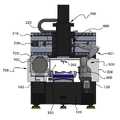
도 1 내지 도 3은 본 발명의 일 실시예에 따른 로봇 자동화 공작기계를 여러 각도에서 바라 본 구성을 각각 나타낸 도면들이다.
도 4는 본 발명의 다른 일 실시예에 따른 로봇 자동화 공작기계를 후면부 쪽에서 바로 본 구성을 나타낸 도면이다.
도 5는 본 발명의 일 실시예에 따른 로봇 자동화 공작기계의 제어계통을 나타낸 블록도이다.
도 6은 본 발명의 일 실시예에 따른 로봇 자동화 공작기계에 이용되는 로봇 핸들러의 구성을 나타낸 도면이다.
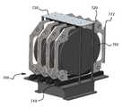
도 7은 본 발명의 일 실시예에 따른 로봇 자동화 공작기계에 이용되는 트레이를 적재하는 스태커에 대해 나타낸 도면이다.
도 8은 본 발명의 일 실시예에 따른 로봇 자동화 공작기계에 이용되는 트레이와 로봇 핸들러의 그립퍼에 대해 나타낸 도면이다.
도 9는 본 발명의 일 실시예에 따른 로봇 자동화 공작기계에 이용되는 로봇 핸들러의 그립퍼의 구성에 대해 나타낸 도면이다.1 to 3 are views each showing the configuration of the robot automated machine tool viewed from various angles according to an embodiment of the present invention.
Figure 4 is a view showing a configuration directly viewed from the rear side of the robot automated machine tool according to another embodiment of the present invention.
5 is a block diagram illustrating a control system of a robot automated machine tool according to an embodiment of the present invention.
6 is a diagram showing the configuration of a robot handler used in a robot automated machine tool according to an embodiment of the present invention.
7 is a view showing a stacker for loading a tray used in a robot automated machine tool according to an embodiment of the present invention.
8 is a view showing a tray and a gripper of a robot handler used in an automated robot machine tool according to an embodiment of the present invention.
9 is a diagram illustrating a configuration of a gripper of a robot handler used in a robot automated machine tool according to an embodiment of the present invention.
본 발명에 따른 로봇 자동화 공작기계, 이에 이용되는 로봇 핸들러 및 그 제어방법에 관하여 도면을 참조하여 상세하게 설명하도록 한다.A robot automated machine tool according to the present invention, a robot handler used therefor, and a control method thereof will be described in detail with reference to the drawings.
먼저, 도 1 내지 도 3을 참조하여 본 발명의 일 실시예에 따른 로봇 자동화 공작기계에 관하여 설명한다.First, an automated robot machine tool according to an embodiment of the present invention will be described with reference to FIGS. 1 to 3 .
도 1 내지 도 3은 본 발명의 일 실시예에 따른 로봇 자동화 공작기계를 여러 각도에서 바라 본 도면들이다.1 to 3 are views viewed from various angles of the robot automated machine tool according to an embodiment of the present invention.
도 1 내지 도 3에 도시된 바와 같이, 본 발명의 일 실시예에 따른 로봇 자동화 공작기계는 베드(100)와, 머신몸체(300)와, 주축장치(200)와, 테이블 장치(400) 등을 포함하도록 구성될 수 있다.1 to 3, the robot automated machine tool according to an embodiment of the present invention includes a
상기 베드(100)는 바닥에 설치되어 공작기계의 기초를 제공하는 구조물로서, 피가공물에 대한 가공이 이루어지는 테이블 장치(400)가 이동할 수 있는 레일 또는 가이드를 구비하도록 구성될 수 있다.The
상기 머신몸체(300)는 주축장치(200)를 지지하며 테이블 장치(400) 위의 피가공물을 주축장치(200)의 하단에 장착된 가공기(202)가 가공 작업을 수행하는 가공공간부(320)를 형성하도록 구성될 수 있다.The
도 1 내지 도 3에 도시된 바와 같이, 머신몸체(300)와 함께 구비되는 크로스레일(210)이 주축장치(200)를 지지하도록 구성될 수 있으며, 크로스레일(210)에 구비된 스크류(220) 및 스크류 구동모터(230)는 상기 주축장치(200)가 크로스레일(210)에 의해 지지된 채 수평 방향으로 이동할 수 있도록 구성될 수 있다.1 to 3 , a
상기 주축장치(200)는 테이블 장치(400)에 놓인 피가공물을 가공하는 가공기(202)를 장착하며 그 가공기(202)를 회전시키거나 수직 방향으로 이동시키는 등의 가공 동작을 수행하도록 할 수 있다.The
상기 테이블 장치(400)는 피가공물(702)을 고정한 트레이(720)가 로드될 수 있도록 구성되며, 트레이(720)가 테이블 장치(400)에 로드되어 세팅되면 주축장치(200)를 구동시켜 트레이(720) 상의 피가공물(702)에 대한 가공이 이루어지도록 할 수 있다.The
본 발명의 일 실시예에 따른 로봇 자동화 공작기계는, 도 1 내지 도 3에 도시된 바와 같이 피가공물(702)을 고정한 트레이(720) 다수가 적재되는 스태커(700)와, 테이블 장치(400)로부터 가공이 완료된 트레이를 파지하여 언로드하고 스태커(700)로부터 가공할 트레이(720)를 파지하여 테이블 장치(400)에 로드하는 로봇 핸들러(500)를 구비하는 것을 특징으로 한다.A robot automated machine tool according to an embodiment of the present invention, as shown in FIGS. 1 to 3 , a
본 발명의 일 실시예에 따른 로봇 자동화 공작기계는, 머신몸체(300)의 가공공간부(320)를 사이에 두고 일측에 스태커(700)가 설치되고 타측에 로봇 핸들러(500)가 설치되도록 구성될 수 있다.The robot automated machine tool according to an embodiment of the present invention is configured such that the
예컨대, 도 1 내지 도 3에 도시된 바와 같이 베드(100)의 일측에 제1 설치부(120)를 구비하고 그 제1 설치부(120) 상에 로봇 핸들러(500)를 설치하고, 베드(100)의 타측 상기 로봇 핸들러(500)와 마주하는 위치에 제2 설치부(140)를 구비하여, 상기 제2 설치부(140) 상에 스태커(700)를 설치할 수 있다.For example, as shown in FIGS. 1 to 3, the
상기 로봇 핸들러(500)는 다축·다관절의 로봇암(501)을 갖도록 구성될 수 있고 로봇암(501)의 단부에 트레이(720)를 파지할 수 있도록 그립퍼(600)를 장착하도록 구성될 수 있다.The
즉, 상기 로봇 핸들러(500)는 공간 좌표계를 이루는 3축의 각 축 방향을 중심으로 회전할 수 있는 로봇암(501)을 동작시켜 스태커(700)에서 가공할 트레이(720)를 집어서 테이블 장치(400)에 로드하고, 피가공물에 대한 가공이 완료되었을 때 상기 로봇암(501)을 동작시켜 테이블 장치(400) 상의 트레이를 집어서 언로드하여 스태커(700)에 원위치시키도록 하며, 이와 같은 동작들을 제어부의 제어에 따라 자동으로 수행하도록 구성할 수 있다.That is, the
가공기에 의한 가공이 이루어지는 피가공물(702)은 트레이(720)라는 프레임에 고정된 채 가공 작업에 투입되며, 상기 스태커(700)는 로봇 핸들러(500)가 각 트레이(720)를 용이하게 파지할 수 있도록 트레이(720) 다수개가 적재되도록 구비될 수 있다.The
로봇 핸들러(500)가 트레이(720)를 파지하여 테이블 장치(400)에 로드하고 테이블 장치(400)로부터 가공이 끝난 트레이(720)를 언로드하는 일련의 프로세스는 로봇 핸들러(500)에 의해 자동으로 수행되는데, 스태커(700)에 다수의 트레이(720)를 적재하는 것은 작업자에 의해 이루어질 수 있다.A series of processes in which the
한편, 도 1 및 도 3에 도시된 바와 같이, 스태커(700)와 로봇 핸들러(500)는 공작기계의 전면부에 배치될 수도 있고, 도 4에 도시된 바와 같이 스태커(700)와 로봇 핸들러(500)가 공작기계의 후면부에 배치되도록 구성될 수도 있다.On the other hand, as shown in FIGS. 1 and 3, the
도 4는 본 발명의 다른 일 실시예에 따른 로봇 자동화 공작기계의 구성을 나타낸 도면으로서, 베드(100)의 후면 쪽에 구비되는 후면 베드(101)의 좌우측에 각각 제1 설치부(121)와 제2 설치부(141)를 마련하고, 제1 설치부(121)에 로봇 핸들러(500)를, 제2 설치부(141)에 스태커(700)를 각각 설치한 상태를 나타낸다.4 is a view showing the configuration of a robot automated machine tool according to another embodiment of the present invention, the
도 1 내지 도 3에 도시된 바와 같이 공작기계의 전면부에 스태커와 로봇 핸들러를 구비할 경우, 관리자는 공작기계의 전면부 쪽에 위치하여 피가공물에 대한 가공 상태의 관리 감독을 하기 때문에 로봇 핸들러의 동작 상태를 살펴보기 쉽게 스태커에 새로운 트레이들을 쉽게 적재할 수 있는 반면, 스태커와 로봇 핸들러 때문에 테이블 장치에서 가공이 이루어지는 상태를 관찰하는 것이 불편하고 테이블 장치의 유지 보수 등의 작업을 하는 것이 불편하다는 등의 단점이 있다.As shown in FIGS. 1 to 3 , when a stacker and a robot handler are provided on the front part of the machine tool, the manager is located on the front part of the machine tool to manage and supervise the processing state for the workpiece, so the robot handler's While new trays can be easily loaded into the stacker for easy viewing of the operation status, it is inconvenient to observe the processing status on the table unit due to the stacker and robot handler, and it is inconvenient to perform tasks such as maintenance of the table unit, etc. has the disadvantage of
도 4에 도시된 바와 같이 공작기계의 후면부에 스태커와 로봇 핸들러를 구비할 경우, 관리자가 주로 전면부 쪽에 위치하기 때문에 로봇 핸들러의 동작 상태를 모니터링 하기는 어렵지만, 테이블 장치에 대한 접근이 용이하고 가까이에서 관찰하기 용이하며 테이블 장치의 유지 보수 등의 작업이 용이한 장점이 있다.As shown in FIG. 4, when the stacker and the robot handler are provided on the rear side of the machine tool, it is difficult to monitor the operation status of the robot handler because the manager is mainly located on the front side, but the access to the table device is easy and close It is easy to observe at the table and has the advantage of easy operation such as maintenance of the table device.
한편, 머신몸체(300)에 형성된 가공공간부(320)에 구비된 테이블 장치(400) 상에 트레이가 장착되고 트레이의 피가공물이 가공기(202)에 의해 가공될 때, 예컨대 피가공물에 미세한 홀을 형성하는 드릴링 작업을 할 때 절삭유를 피가공물에 공급하면서 드릴링이 이루어지는데, 이때 절삭유가 테이블 장치(400)로부터 주변으로 비산하기 때문에, 그와 같이 가공 과정에서 발생하는 절삭유의 비산에 의해 스태커(700)에 적재된 트레이들과 로봇 핸들러(500)가 오염될 수 있다.On the other hand, when the tray is mounted on the
따라서, 본 발명의 일 실시예에 따른 로봇 자동화 공작기계는, 도 1 내지 도 4에 도시된 바와 같이 머신몸체(300)의 가공공간부(320)를 개폐할 수 있도록 하는 스크린 도어(340)를 머신몸체에 설치할 수 있다.Therefore, the robot automated machine tool according to an embodiment of the present invention, as shown in Figs. 1 to 4, the
도 1 내지 도 4에 도시된 바와 같은 스크린 도어(340)는 투명한 재질로 만들어져 폐쇄된 상태에서 내부의 테이블 장치(400) 상의 피가공물에 대한 가공이 이루어질 때 외부에서 관찰이 가능하도록 함이 바람직하다.The
상기 스크린 도어(340)는 머신몸체에 별도의 모터를 장착하고 이에 의해 가공공간부(320)를 개방하거나 폐쇄하도록 구동될 수 있고, 도 4에 도시된 바와 같이 머신몸체에 고정된 실린더(350)에 의해 상하로 슬라이드함에 의해 가공공간부를 개방 또는 폐쇄할 수 있다.The
도면상으로 도시되지는 않았으나, 본 발명의 일 실시예에 따른 로봇 자동화 공작기계는 제어부에 의해 제어되어 작동할 수 있고 상기한 스크린 도어(340) 역시 제어부에 의해 제어되어 작동할 수 있는데, 제어부는 테이블 장치(400)에 트레이(720)가 로드 되어 가공기에 의한 피가공물의 가공이 이루어질 때 스크린 도어(340)를 폐쇄함으로써 가공 공정 시 비산되는 절삭유가 외부의 스태커와 로봇 핸들러를 오염시키는 것을 방지할 수 있고, 테이블 장치 상의 피가공물에 대한 가공이 완료된 후에는 로봇 핸들러(500)가 테이블 장치 상의 트레이를 언로드 하고 새로운 트레이를 로드 할 수 있도록 스크린 도어(340)를 개방할 수 있다.Although not shown in the drawings, the robot automated machine tool according to an embodiment of the present invention can be operated by being controlled by the control unit, and the
한편, 도 5를 참조하여 본 발명의 일 실시예에 따른 로봇 자동화 공작기계의 제어계통에 대해 설명한다. 도 5는 도 1 내지 도 4에 도시된 실시예에 따른 로봇 자동화 공작기계의 제어계통에 대해 나타낸 블록도이다.On the other hand, the control system of the robot automated machine tool according to an embodiment of the present invention will be described with reference to FIG. 5 . Figure 5 is a block diagram showing the control system of the robot automated machine tool according to the embodiment shown in Figures 1 to 4;
도 5에 도시된 바와 같이 제어부(M)는 본 발명의 일 실시예에 따른 로봇 자동화 공작기계의 주요 구성요소들의 동작을 제어할 수 있다.As shown in Figure 5, the control unit (M) can control the operation of the main components of the robot automated machine tool according to an embodiment of the present invention.
예컨대, 제어부(M)는 수평이동장치(230), 주축장치(200), 절삭유공급장치(160)의 동작을 각각 제어할 수 있고, 스크린 도어(340)와 테이블 장치(400)를 각각 제어할 수 있으며, 로봇 핸들러의 로봇암(501)과 그립퍼(600)의 동작을 제어하는 로봇 제어부(502)를 제어할 수 있다.For example, the control unit M may control the operations of the
상기 수평이동장치(230)는, 도 1 내지 도 3에 도시된 바와 같이 크로스레일(210)에 설치된 스크류(220)를 작동시키는 스크류 구동모터로서 구현될 수 있으며, 제어부(M)의 제어에 따라 주축장치(200)를 수평 방향으로 이동시킬 수 있다.The
상기 주축장치(200)는, 제어부(M)의 제어에 따라 가공기(202)를 장착한 상태에서 가공기를 수직 방향으로 이동시킬 수도 있고 가공기를 회전시킬 수도 있다.The
상기 절삭유 공급장치(160)는 제어부(M)의 제어에 따라, 가공기(202)가 피가공물을 가공할 때 절삭유를 공급할 수 있다.The cutting
또한, 제어부(M)는 피가공물을 고정한 트레이를 테이블 장치에 올려놓고 테이블 장치가 트레이를 세팅 및 고정하며, 피가공물에 대한 가공이 이루어진 후 테이블 장치 상의 트레이를 다시 꺼내는 일련의 프로세스를 수행하기 위하여, 스크린 도어(230), 테이블 장치(400), 로봇 제어부(501)를 각각 제어할 수 있다.In addition, the control unit (M) puts the tray on which the workpiece is fixed on the table device, the table device sets and fixes the tray, and after the processing on the workpiece is made, the tray on the table device is taken out again to perform a series of processes. , the
예컨대, 제어부(M)는 스크린 도어(340)를 개방하고, 로봇 제어부(502)를 제어하여 상기 로봇 제어부(502)가 로봇암(501)을 스태커로 동작하게 하고 그립퍼(600)가 트레이를 파지하도록 하며 다시 로봇암을 움직여 파지한 트레이를 테이블 장치에 올려놓도록 제어하게 할 수 있다.For example, the control unit M opens the
이어서, 제어부(M)는 테이블 장치에 올려진 트레이가 고정되도록 하고 스크린 도어(340)를 폐쇄하며, 주축장치(200) 등을 제어하여 가공기가 테이블 장치 위의 피가공물을 가공하도록 할 수 있다.Then, the control unit M may fix the tray mounted on the table device, close the
피가공물에 대한 가공이 완료되면, 제어부(M)는 스크린 도어(340)를 개방하고, 로봇 제어부(502)를 제어하여 상기 로봇 제어부(502)가 로봇암(501)을 움직여 테이블 장치로 이동하게 하고 그립퍼가 테이블 장치에 올려진 트레이를 파지하도록 하며 다시 로봇암을 움직여 트레이를 스태커에 위치시키도록 제어하게 할 수 있다.When the processing of the workpiece is completed, the control unit M opens the
한편, 도 6을 참조하여 본 발명의 일 실시예에 따른 로봇 핸들러(500)에 관하여 설명한다.Meanwhile, a
도 6에 도시된 바와 같이, 로봇 핸들러(500)는 기초를 이루는 로봇 베이스(510)와, 다축·다관절의 로봇암(501)과, 로봇암(501)의 단부에 트레이(720)를 파지할 수 있도록 장착된 그립퍼(600)를 포함하여 구성될 수 있다.As shown in FIG. 6 , the
상기 로봇암(501)은 로봇 베이스(510)에 회전 가능하도록 설치되고 x-y-z 좌표계에 의한 좌표 공간에서 각 축 방향으로 각각 회전할 수 있도록 구성될 수 있으며, 상기 그립퍼(600)는 제1 그립핑거(610)와 제2 그립핑거(620)가 각각 슬라이드 이동할 수 있도록 구비할 수 있다.The
도 6에 도시된 바와 같이 로봇암(501)은, 로봇 베이스(510)에 대해 z축 방향을 기준으로 회전(a) 가능하도록 설치되는 제1 관절(520)과, 제1 관절(520)에 y축 방향을 기준으로 회전(b) 가능하도록 구비되는 제1 암(530)과, 제1 암(530)의 단부에 구비되는 제2 관절(540)과, 제2 관절(540)에 y축 방향을 기준으로 회전(c) 가능하도록 구비되는 제2 암(550)을 포함하여 구성될 수 있다.As shown in FIG. 6 , the
상기 제2 암(550)은, 도 6에 도시된 바와 같이 포어암(552)이 x축 방향을 기준으로 회전(d)하도록 구성될 수 있으며, 포어암(552)에 의해 그립퍼(600)가 d 회전을 하도록 구성될 수 있다.The
따라서, 상기한 바와 같은 로봇암(501)은 그립퍼(600)를, 도 1 내지 도 4에 도시된 바와 같이 스태커(700)와 가공공간부(320)에 구비된 테이블 장치(400)로 정확하게 동작하여 이동시킬 수 있도록 각각의 회전(a, b, c, d)이 정확하게 이루어지도록 로봇 제어부에 의해 제어될 수 있다.Accordingly, the
한편, 도 7 내지 도 9를 참조하여 상기한 로봇 핸들러의 그립퍼가 트레이를 파지할 수 있는 구조 및 동작 메커니즘에 대해 설명한다.Meanwhile, a structure and an operation mechanism capable of gripping the tray by the gripper of the robot handler described above will be described with reference to FIGS. 7 to 9 .
도 7에서는 다수의 트레이(720)가 적재된 스태커(700)에 대해 도시하고 있고, 도 8에서는 피가공물(702)을 고정시킨 트레이(720)와 로봇 핸들러의 그립퍼(600)에 대해 나타내고 있으며, 도 9에서는 그립퍼(600)의 구체적인 구성에 대해 나타내고 있다.7 shows a
도 7에 도시된 바와 같이, 스태커(700)는 트레이(720)를 수용하는 수용레일(710) 다수를 구비하고, 각 수용레일(710)에 수용된 트레이(720)의 적재된 상태를 지지하는 적재 프레임(730)을 구비하여 구성될 수 있다.As shown in Figure 7, the
다수의 수용레일(710)과 적재 프레임(730)에 의해, 도 7에 도시된 바와 같이 다수의 트레이(720)를 스태커(700)에 적재할 수 있다.By the plurality of
한편, 도 8에 도시된 바와 같이, 트레이(720)는, 전체 틀을 형성하며 피가공물(702)을 수용할 수 있도록 개구된 지지프레임(721)과, 지지프레임(721)의 개구된 내부에 피가공물(702)이 위치한 상태를 지지하는 내부지지부(Z1, Z2, Z3, Z4)와, 각각의 내부지지부(Z1, Z2, Z3, Z4)에 구비되어 피가공물(702)이 내부지지부(Z1, Z2, Z3, Z4)에 지지된 상태에서 피가공물(702)을 고정시키는 고정클립(C1, C2, C3, C4)을 구비하며, 지지프레임(721)의 일단부에는 그립퍼(600)가 파지할 수 있도록 트레이 그립(722)이 구비될 수 있다.On the other hand, as shown in FIG. 8 , the
상기한 지지프레임(721)에는 위치맞춤 홀(H1, H2, H3, H4)이 구비될 수 있고, 각각의 위치맞춤 홀은 트레이(720)가 테이블 장치에 로드 될 때 테이블 장치 상에 구비된 위치맞춤 핀에 대응되어, 각 위치맞춤 핀이 상기 트레이의 각 위치맞춤 홀에 모두 결합이 됨에 따라 트레이가 테이블 장치에 정확하게 세팅되도록 할 수 있다.Positioning holes H1, H2, H3, and H4 may be provided in the
상기 트레이 그립(722)은 그립퍼(600)의 제1 그립핑거(610)와 제2 그립핑거(620)가 움켜잡기 용이한 형태로 형성됨이 바람직하며, 도 8에 도시된 바와 같이 일자로 길게 형성된 블레이드 형상을 갖도록, 즉 끝으로 갈수록 단면이 좁아지도록 S1 경사면과 S2 경사면을 갖는 형상으로 형성될 수 있다. 또한, 트레이 그립(722)은 양단에 각각 돌출된 단턱(723, 724)을 형성하도록 형성될 수 있다.The
로봇 핸들러의 그립퍼(600)는 그립퍼 지지부(630)에 지지되는 제1 그립핑거(610)와 제2 그립핑거(620)가 길이 방향으로 나란히 배치되며, 그립퍼 지지부(630)에서 제1 그립핑거(610) 및 제2 그립핑거(620)가 도 8에 도시된 바와 같이 화살표 방향으로 각각 슬라이드 이동이 가능하도록 구성될 수 있다.In the
따라서, 상기한 트레이 그립(722)이 그립퍼(600)의 제1 그립핑거(610)와 제2 그립핑거(620)에 각각 수용되어 상기 제1 그립핑거(610)가 도면상 아래 방향으로, 그리고 제2 그립핑거(620)가 도면상 윗 방향으로 각각 슬라이드 이동함으로써(즉, 제1 그립핑거(610)와 제2 그립핑거(620)가 각각 중심 방향으로 슬라이드 이동함으로써) 상기 제1 그립핑거(610) 및 제2 그립핑거(620)가 트레이 그립(722)을 파지할 수 있게 된다.Accordingly, the
이에 대해 도 9를 이용하여 좀 더 상세하게 설명하면, 도 9의 (a) 및 (b)에 도시된 바와 같이 제1 그립핑거(610)는 트레이 그립(722)을 일측 단턱(723)으로부터 소정 구간까지를 수용할 수 있도록 제1 홈부(612)를 형성하고 중심부로부터의 원위단에 제1 핑거엔드(613)를 구비하며, 제2 그립핑거(620)는 트레이 그립(722)을 타측 단턱(724)으로부터 소정 구간까지를 수용할 수 있도록 제2 홈부(622)를 형성하고 중심부로부터의 원위단에 제2 핑거엔드(623)를 구비할 수 있다.Referring to Fig. 9 in more detail, as shown in Figs. 9 (a) and (b), the
또한, 도 9의 (b)에 도시된 바와 같이, 제1 그립핑거(610)의 제1 홈부(612) 및 제2 그립핑거(620)의 제2 홈부(622)는 홈 안쪽으로 갈수록 점점 좁아지도록 측벽이 경사를 형성하도록 구성될 수 있다. 즉, 제1 홈부(612) 및 제2 홈부(622)는 일측벽이 R1 경사면을 갖고 타측벽이 R2 경사면을 갖는다.Also, as shown in FIG. 9B , the
따라서, 상기한 트레이 그립(722)이 그립퍼(600)의 제1 그립핑거(610)와 제2 그립핑거(620)에 수용될 때, 트레이 그립(722)의 S1 경사면과 S2 경사면이 제1 홈부(612) 및 제2 홈부(622)의 R1 경사면과 R2 경사면을 따라 슬라이드 핏 되어 결합될 수 있다.Therefore, when the
또한, 도 9의 (b)에 도시된 바와 같이 제1 핑거엔드(613)에는 움푹 패인 제1 결합홈(614)이 형성되고, 도면상 도시되지는 않았으나 제2 핑거엔드(623)에도 마찬가지로 움푹 패인 제2 결합홈이 형성될 수 있다.In addition, as shown in (b) of FIG. 9 , a dented
따라서, 상기한 트레이 그립(722)이 그립퍼(600)의 제1 그립핑거(610)와 제2 그립핑거(620)에 수용될 때, 트레이 그립(722)의 일측 단턱(723)이 제1 핑거엔드(613)의 제1 결합홈(614)에 결합하고 트레이 그립(722)의 타측 단턱(724)이 제2 핑거엔드(623)의 제2 결합홈에 결합함으로써 그립퍼(600)가 트레이 그립(722)을 안정적으로 파지할 수 있게 된다.Accordingly, when the
또한, 도 8 및 도 9의 (a)에 도시된 바와 같이, 그립퍼 구동부(640)가 구비되고 그립퍼 지지부(630)에는 제1 슬라이드바(615)와 제2 슬라이드바(625)가 각각 그립퍼 구동부(640)에 의해 구동되어 각각 슬라이드 이동할 수 있도록 구성되어, 상기 제1 슬라이드바(615)가 제1 그립핑거(610)를 슬라이드 이동시키고, 상기 제2 슬라이드바(625)가 제2 그립핑거(620)를 슬라이드 이동시키도록 구성될 수 있다.In addition, as shown in FIGS. 8 and 9A , a
따라서, 상기한 트레이 그립(722)이 그립퍼(600)의 제1 그립핑거(610)와 제2 그립핑거(620)에 수용될 때, 트레이 그립(722)의 S1 경사면과 S2 경사면이 제1 홈부(612) 및 제2 홈부(622)의 R1 경사면과 R2 경사면을 따라 슬라이드 핏 되면서 수용되고, 이어서 그립퍼 구동부(630)에 의해 제1 슬라이드바(615)와 제2 슬라이드바(625)가 각각 재1 그립핑거(610) 및 제2 그립핑거(620)를 중심 방향으로 슬라이드 이동시키면서 트레이 그립(722)의 일측 단턱(723)이 제1 핑거엔드(613)의 제1 결합홈(614)에 끼워져서 결합하고 트레이 그립(722)의 타측 단턱(724)이 제2 핑거엔드(623)의 제2 결합홈에 끼워져서 결합함으로써 그립퍼(600)가 트레이 그립(722)을 안정적으로 파지할 수 있게 된다.Therefore, when the
이와 같이 본 발명의 일 실시예에 따른 로봇 자동화 공작기계는, 피가공물(702)을 고정한 트레이(720) 다수가 적재되는 스태커(700)와, 트레이(720)의 단부에 구비되는 트레이 그립(722)을 안정적으로 파지하여 테이블 장치로 로딩하거나 가공이 완료된 후의 트레이를 테이블 장치로부터 언로딩하는 로봇 핸들러(500)를 구비하여, 피가공물의 로딩 및 언로딩 작업이 로봇 핸들러에 의해 신속하고 정확하게, 그리고 자동으로 이루어지기 때문에 생산성을 크게 향상시킬 수 있는 특장점이 있다.As described above, the robot automated machine tool according to an embodiment of the present invention includes a
100: 베드, 120: 제1 설치부
140: 제2 설치부, 200: 주축장치
202: 가공기, 210: 크로스레일
220: 스크류, 230: 스크류 구동모터
300: 머신몸체, 320: 가공공간부
340: 스크린 도어, 400: 테이블 장치
500: 로봇 핸들러, 501: 로봇암
510: 로봇 베이스, 520: 제1 관절
530: 제1 암. 540: 제2 관절
550: 제2 암, 600: 그립퍼
610: 제1 그립핑거, 620: 제2 그립핑거
630: 그립퍼 지지부, 640: 그립퍼 구동부
700: 스태커, 702: 피가공물
720: 트레이, 722: 트레이 그립100: bed, 120: first installation part
140: second installation unit, 200: spindle device
202: processing machine, 210: cross rail
220: screw, 230: screw drive motor
300: machine body, 320: processing space part
340: screen door, 400: table device
500: robot handler, 501: robot arm
510: robot base, 520: first joint
530: first arm. 540: second joint
550: second arm, 600: gripper
610: first gripping finger, 620: second gripping finger
630: gripper support part, 640: gripper driving part
700: stacker, 702: work piece
720: tray, 722: tray grip
Claims (12)
Translated fromKorean상기 테이블 장치에 놓인 피가공물을 가공하는 가공기가 장착되는 주축장치;
상기 주축장치를 지지하며 상기 테이블 장치 상의 피가공물을 상기 가공기가 가공하는 가공공간부를 형성하는 머신몸체;
상기 피가공물을 고정하여 상기 테이블 장치에 로드되는 트레이 다수가 적재되는 스태커; 및
상기 테이블 장치로부터 가공이 완료된 트레이를 파지하여 언로드하고, 상기 스태커로부터 가공할 트레이를 파지하여 상기 테이블 장치에 로드하는 로봇 핸들러를 포함하며,
상기 트레이는,
상기 피가공물을 고정시키는 복수의 고정클립과, 상기 고정클립에 의해 고정된 피가공물을 지지하는 지지프레임과, 상기 지지프레임의 일측에 구비된 트레이 그립을 포함하며,
상기 로봇 핸들러는,
로봇 베이스와, 상기 로봇 베이스에 회전 가능하도록 설치되고 복수 관절을 가진 로봇암과, 상기 로봇암의 단부에 설치되어 상기 트레이 그립을 파지할 수 있도록 구비되는 그립퍼를 포함하는 로봇 자동화 공작기계.a table device that is movably installed on the bed and on which the workpiece is placed;
a spindle device on which a processing machine for processing a workpiece placed on the table device is mounted;
a machine body supporting the spindle device and forming a processing space in which the processing machine processes the workpiece on the table device;
a stacker on which a plurality of trays loaded on the table device are loaded by fixing the workpiece; and
and a robot handler that grips and unloads the tray on which processing is completed from the table device, and grips the tray to be processed from the stacker and loads it into the table device,
The tray is
A plurality of fixing clips for fixing the workpiece, a support frame for supporting the workpiece fixed by the fixing clips, and a tray grip provided on one side of the support frame,
The robot handler is
A robot automatic machine tool comprising: a robot base; a robot arm rotatably installed on the robot base and having a plurality of joints; and a gripper installed at an end of the robot arm to grip the tray grip.
상기 가공공간부를 사이에 두고 일측에 상기 스태커가 설치되고, 타측에 상기 로봇 핸들러가 설치되어 구성되는 것을 특징으로 하는 로봇 자동화 공작기계.According to claim 1,
A robot automated machine tool, characterized in that the stacker is installed on one side with the processing space portion interposed therebetween, and the robot handler is installed on the other side.
상기 가공공간부를 개폐하도록 구성되며, 상기 테이블 장치에 로드된 트레이의 피가공물에 대한 가공이 이루어지는 동안에는 폐쇄되고, 상기 로봇 핸들러에 의한 트레이의 언로드와 로드가 이루어질 때에는 개방이 되는 스크린 도어를 더 포함하는 것을 특징으로 하는 로봇 자동화 공작기계.According to claim 1,
It is configured to open and close the processing space, and is closed while the processing of the workpiece of the tray loaded on the table device is made, and further comprising a screen door that is opened when unloading and loading of the tray by the robot handler is made Robot automation machine tool, characterized in that.
피가공물에 대한 가공이 완료된 후 상기 테이블 장치 상의 트레이의 트레이 그립을 상기 그립퍼가 파지하도록 상기 로봇암을 동작시키고 상기 로봇암이 동작하여 상기 그립퍼에 의해 파지된 트레이를 상기 스태커에 적재되도록 하며,
상기 스태커에서 가공할 트레이의 트레이 그립을 상기 그립퍼가 파지하고 상기 파지된 트레이가 상기 테이블 장치에 로드되도록 상기 로봇암을 동작시키도록 하는 것을 특징으로 하는 로봇 자동화 공작기계.According to claim 1, wherein the robot handler,
After processing of the workpiece is completed, the robot arm is operated so that the gripper grips the tray grip of the tray on the table device, and the robot arm operates to load the tray gripped by the gripper on the stacker,
The robot automatic machine tool, characterized in that the gripper grips the tray grip of the tray to be processed in the stacker and operates the robot arm so that the gripped tray is loaded into the table device.
상기 그립퍼는 상기 트레이 그립이 수용되는 홈부를 형성하여 상기 트레이 그립이 상기 그립퍼의 홈부에 슬라이드 핏 되어 결합되도록 구성되는 것을 특징으로 하는 로봇 자동화 공작기계.According to claim 1,
The gripper is configured to form a groove portion in which the tray grip is accommodated so that the tray grip is slide-fitted to the groove portion of the gripper and coupled thereto.
상기 로봇암의 단부에 구비되는 그립퍼 구동부와, 상기 트레이 그립을 수용하는 제1 홈부를 가지며 슬라이드 하도록 구성되는 제1 그립핑거와, 상기 트레이 그립을 수용하는 제2 홈부를 가지며 슬라이드 하도록 구성되는 제2 그립핑거를 포함하여,
상기 제1 그립핑거의 제1 홈부 및 제2 그립핑거의 제2 홈부가 상기 트레이 그립을 수용한 상태로 상기 그립퍼 구동부가 상기 제1 그립핑거 및 상기 제2 그립핑거를 각각 슬라이드 이동시켜 상기 트레이 그립을 파지하도록 구성되는 것을 특징으로 하는 로봇 자동화 공작기계.According to claim 1, wherein the gripper,
A gripper driving part provided at an end of the robot arm, a first gripping finger having a first groove for accommodating the tray grip and configured to slide, and a second groove having a second groove for accommodating the tray grip and configured to slide Including grip fingers,
In a state in which the first groove portion of the first grip finger and the second groove portion of the second grip finger receive the tray grip, the gripper driving unit slides the first grip finger and the second grip finger, respectively, to the tray grip. Robot automated machine tool, characterized in that configured to grip.
상기 로봇 베이스에 대해 수직축을 기준으로 회전 가능하도록 설치되는 제1 관절과, 일단부가 상기 제1 관절에 대해 상기 수직축과 수직인 축을 기준으로 회전 가능하며 타단부에 제2 관절을 구비하는 제1 암과, 상기 제2 관절에 대해 회전 가능하게 설치되는 제2 암을 포함하며,
상기 제2 암의 단부에 상기 제2 암의 축 방향을 기준으로 회전 가능하며 상기 트레이를 파지할 수 있도록 구비되는 그립퍼를 포함하는 것을 특징으로 하는 로봇 자동화 공작기계.According to claim 1, wherein the robot arm,
A first arm having a first joint rotatably installed on the basis of a vertical axis with respect to the robot base, one end rotatable with respect to the first joint on an axis perpendicular to the vertical axis with respect to the first joint, and a second joint on the other end and a second arm rotatably installed with respect to the second joint,
and a gripper at an end of the second arm that is rotatable based on the axial direction of the second arm and is provided to grip the tray.
상기 가공공간부와 인접한 위치에 설치되는 로봇 베이스;
상기 로봇 베이스에 회전 가능하도록 설치되고 복수 관절을 가진 로봇암;
상기 로봇암의 단부에 설치되어 상기 트레이에 구비된 트레이 그립을 파지할 수 있도록 구비되는 그립퍼; 및
피가공물의 가공을 위하여 상기 트레이를 상기 테이블 장치에 로드하거나, 피가공물에 대한 가공 완료된 트레이를 상기 테이블 장치로부터 언로드하도록 상기 로봇암 및 그립퍼의 동작을 제어하는 로봇 제어부를 포함하며,
상기 그립퍼는 상기 트레이 그립이 수용되는 홈부를 형성하여, 상기 그립퍼가 상기 트레이 그립을 파지할 때 상기 트레이 그립이 상기 그립퍼의 홈부에 슬라이드 핏 되어 결합되도록 구성되는 공작기계에 이용되는 로봇 핸들러.A robot handler used in a machine tool comprising a machine body, a processing space formed thereon, and a table device installed in the processing space, and configured to load a tray in which a workpiece is fixed to the table device,
a robot base installed in a position adjacent to the processing space;
a robot arm rotatably installed on the robot base and having a plurality of joints;
a gripper installed at an end of the robot arm to grip a tray grip provided on the tray; and
and a robot control unit for controlling the operation of the robot arm and the gripper to load the tray into the table device for processing of the workpiece or unload the tray that has been processed for the workpiece from the table device,
The gripper forms a groove portion in which the tray grip is accommodated, so that when the gripper grips the tray grip, the tray grip is slide-fitted and coupled to the groove portion of the gripper.
상기 머신몸체의 일측에 구비된 로봇 핸들러의 다축·다관절 로봇암이 동작하여 그립퍼가 피가공물을 고정시킨 트레이의 트레이 그립에 위치하도록 제어하는 단계;
상기 로봇 핸들러의 그립퍼가 상기 트레이 그립을 파지하도록 제어하는 단계;
상기 로봇 핸들러의 로봇암이 동작하여 상기 그립퍼가 파지한 트레이가 상기 가공공간부에 구비된 상기 테이블 장치에 로드되도록 하는 단계; 및
상기 테이블 장치에 로드된 트레이의 피가공물에 대해 상기 가공기에 의한 가공이 이루어지는 단계를 포함하며,
상기 그립퍼가 상기 트레이 그립에 위치하도록 제어하는 단계가 수행되기 전에, 상기 가공공간부를 개폐하도록 구비된 스크린 도어를 개방하는 단계를 더 포함하며,
상기 트레이가 상기 테이블 장치에 로드되도록 하는 단계가 수행된 후 상기 가공기에 의한 가공이 이루어지기 전에 상기 스크린 도어를 폐쇄하는 단계를 더 포함하는 로봇 자동화 공작기계의 제어방법.As a control method of a robot automated machine tool having a machine body forming a processing space in which a table device on which the workpiece is loaded is provided so that the processing machine processes the workpiece,
controlling the multi-axis and multi-joint robot arm of the robot handler provided on one side of the machine body so that the gripper is positioned on the tray grip of the tray to which the workpiece is fixed;
controlling the gripper of the robot handler to grip the tray grip;
operating the robot arm of the robot handler to load the tray gripped by the gripper onto the table device provided in the processing space; and
Including the step of making the processing by the processing machine for the workpiece of the tray loaded on the table device,
Before the step of controlling the gripper to be positioned on the tray grip is performed, the method further comprising: opening a screen door provided to open and close the processing space;
After the step of loading the tray into the table device is performed, the control method of the robot automated machine tool further comprising the step of closing the screen door before processing by the processing machine is performed.
Priority Applications (1)
| Application Number | Priority Date | Filing Date | Title |
|---|---|---|---|
| KR1020220017463AKR102459650B1 (en) | 2022-02-10 | 2022-02-10 | Robot-automated machine tool, robot handler used to machine tool and control method for the same |
Applications Claiming Priority (1)
| Application Number | Priority Date | Filing Date | Title |
|---|---|---|---|
| KR1020220017463AKR102459650B1 (en) | 2022-02-10 | 2022-02-10 | Robot-automated machine tool, robot handler used to machine tool and control method for the same |
Publications (1)
| Publication Number | Publication Date |
|---|---|
| KR102459650B1true KR102459650B1 (en) | 2022-10-27 |
Family
ID=83810364
Family Applications (1)
| Application Number | Title | Priority Date | Filing Date |
|---|---|---|---|
| KR1020220017463AActiveKR102459650B1 (en) | 2022-02-10 | 2022-02-10 | Robot-automated machine tool, robot handler used to machine tool and control method for the same |
Country Status (1)
| Country | Link |
|---|---|
| KR (1) | KR102459650B1 (en) |
Cited By (2)
| Publication number | Priority date | Publication date | Assignee | Title |
|---|---|---|---|---|
| CN116922111A (en)* | 2023-08-10 | 2023-10-24 | 宁波迈拓斯数控机械有限公司 | Workbench convenient for installing machined parts |
| KR102682240B1 (en)* | 2023-07-19 | 2024-07-04 | 김기영 | Pressure workpiece deburring automation system |
Citations (2)
| Publication number | Priority date | Publication date | Assignee | Title |
|---|---|---|---|---|
| JP2004160599A (en)* | 2002-11-13 | 2004-06-10 | Mori Seiki Hitech Co Ltd | Vertical type machining center |
| CN105817948A (en)* | 2015-01-23 | 2016-08-03 | 发那科株式会社 | System capable of immediately performing operation on workpiece |
- 2022
- 2022-02-10KRKR1020220017463Apatent/KR102459650B1/enactiveActive
Patent Citations (3)
| Publication number | Priority date | Publication date | Assignee | Title |
|---|---|---|---|---|
| JP2004160599A (en)* | 2002-11-13 | 2004-06-10 | Mori Seiki Hitech Co Ltd | Vertical type machining center |
| CN105817948A (en)* | 2015-01-23 | 2016-08-03 | 发那科株式会社 | System capable of immediately performing operation on workpiece |
| CN105817948B (en)* | 2015-01-23 | 2018-08-24 | 发那科株式会社 | The system that can operation be carried out to workpiece immediately |
Cited By (2)
| Publication number | Priority date | Publication date | Assignee | Title |
|---|---|---|---|---|
| KR102682240B1 (en)* | 2023-07-19 | 2024-07-04 | 김기영 | Pressure workpiece deburring automation system |
| CN116922111A (en)* | 2023-08-10 | 2023-10-24 | 宁波迈拓斯数控机械有限公司 | Workbench convenient for installing machined parts |
Similar Documents
| Publication | Publication Date | Title |
|---|---|---|
| JP4380756B2 (en) | Manufacturing equipment | |
| KR102459650B1 (en) | Robot-automated machine tool, robot handler used to machine tool and control method for the same | |
| CN109676592B (en) | Automatic assembling method and automatic assembling equipment | |
| JP6563037B2 (en) | Machine tool system | |
| US20210387354A1 (en) | Automatic workpiece carrying machine | |
| US20250235971A1 (en) | Combined transfer and storage device and manufacturing line for machining | |
| US20220379419A1 (en) | Manufacturing system and manufacturing line for machining | |
| WO2014069274A1 (en) | Workpiece carrying apparatus and working machine | |
| JP5624311B2 (en) | Production line and machine tool | |
| JP2004114258A (en) | Machine tool having workpiece conveying device | |
| CN108568693B (en) | Conveying system | |
| JP3780144B2 (en) | Work reversing device | |
| JP6697046B2 (en) | Processing system | |
| US20060075625A1 (en) | Multiple side processing machine and positioning device for a workpiece | |
| TWM448342U (en) | Workpiece moving-out device for machine tool and machine tool | |
| JP2002337080A (en) | Loading device for grinder of shaft-like workpiece | |
| JP2001121301A (en) | Spindle movable vertical machine tool | |
| US20230321731A1 (en) | Combined processing machine | |
| JP3911441B2 (en) | Work delivery device | |
| CN117396303A (en) | Automatic pallet changer | |
| JPH11226801A (en) | Work transfer control method for moving spindle machine tool and numerical control device for moving spindle machine tool | |
| JP7573096B1 (en) | Tool transport device and machining system | |
| US20240173810A1 (en) | Conveyance system | |
| US20240082969A1 (en) | Handling cell for a machine tool and manufacturing system | |
| JP7282542B2 (en) | storage and transfer system |
Legal Events
| Date | Code | Title | Description |
|---|---|---|---|
| PA0109 | Patent application | Patent event code:PA01091R01D Comment text:Patent Application Patent event date:20220210 | |
| PA0201 | Request for examination | ||
| PA0302 | Request for accelerated examination | Patent event date:20220323 Patent event code:PA03022R01D Comment text:Request for Accelerated Examination Patent event date:20220210 Patent event code:PA03021R01I Comment text:Patent Application | |
| PN2301 | Change of applicant | Patent event date:20220419 Comment text:Notification of Change of Applicant Patent event code:PN23011R01D | |
| PE0902 | Notice of grounds for rejection | Comment text:Notification of reason for refusal Patent event date:20220627 Patent event code:PE09021S01D | |
| E701 | Decision to grant or registration of patent right | ||
| PE0701 | Decision of registration | Patent event code:PE07011S01D Comment text:Decision to Grant Registration Patent event date:20221018 | |
| GRNT | Written decision to grant | ||
| PR0701 | Registration of establishment | Comment text:Registration of Establishment Patent event date:20221024 Patent event code:PR07011E01D | |
| PR1002 | Payment of registration fee | Payment date:20221024 End annual number:3 Start annual number:1 | |
| PG1601 | Publication of registration |