KR102458200B1 - A device for the attached flow of blood - Google Patents
A device for the attached flow of bloodDownload PDFInfo
- Publication number
- KR102458200B1 KR102458200B1KR1020227000450AKR20227000450AKR102458200B1KR 102458200 B1KR102458200 B1KR 102458200B1KR 1020227000450 AKR1020227000450 AKR 1020227000450AKR 20227000450 AKR20227000450 AKR 20227000450AKR 102458200 B1KR102458200 B1KR 102458200B1
- Authority
- KR
- South Korea
- Prior art keywords
- blood
- flow
- housing
- attachment
- flow guide
- Prior art date
- Legal status (The legal status is an assumption and is not a legal conclusion. Google has not performed a legal analysis and makes no representation as to the accuracy of the status listed.)
- Active
Links
- 239000008280bloodSubstances0.000titleclaimsdescription154
- 210000004369bloodAnatomy0.000titleclaimsdescription154
- 230000017531blood circulationEffects0.000claimsabstractdescription110
- 238000004891communicationMethods0.000claimsdescription19
- 238000000034methodMethods0.000claimsdescription14
- 239000000945fillerSubstances0.000claimsdescription12
- 239000012530fluidSubstances0.000claimsdescription12
- 230000001464adherent effectEffects0.000claimsdescription10
- 230000009471actionEffects0.000claimsdescription8
- 239000003146anticoagulant agentSubstances0.000description17
- 229940127219anticoagulant drugDrugs0.000description17
- 239000006260foamSubstances0.000description16
- 239000003381stabilizerSubstances0.000description14
- 238000013461designMethods0.000description12
- 238000012986modificationMethods0.000description6
- 230000004048modificationEffects0.000description6
- 239000000843powderSubstances0.000description6
- 239000000463materialSubstances0.000description5
- 239000000654additiveSubstances0.000description4
- 238000012360testing methodMethods0.000description4
- 238000012546transferMethods0.000description4
- 230000000996additive effectEffects0.000description3
- 230000008901benefitEffects0.000description3
- 238000004458analytical methodMethods0.000description2
- 238000003149assay kitMethods0.000description2
- 238000009534blood testMethods0.000description2
- HVYWMOMLDIMFJA-DPAQBDIFSA-NcholesterolChemical compoundC1C=C2C[C@@H](O)CC[C@]2(C)[C@@H]2[C@@H]1[C@@H]1CC[C@H]([C@H](C)CCCC(C)C)[C@@]1(C)CC2HVYWMOMLDIMFJA-DPAQBDIFSA-N0.000description2
- 201000010099diseaseDiseases0.000description2
- 208000037265diseases, disorders, signs and symptomsDiseases0.000description2
- 238000007667floatingMethods0.000description2
- 239000006261foam materialSubstances0.000description2
- 230000005660hydrophilic surfaceEffects0.000description2
- 239000011148porous materialSubstances0.000description2
- 239000000126substanceSubstances0.000description2
- XLYOFNOQVPJJNP-UHFFFAOYSA-NwaterSubstancesOXLYOFNOQVPJJNP-UHFFFAOYSA-N0.000description2
- 229920005832Basotect®Polymers0.000description1
- KCXVZYZYPLLWCC-UHFFFAOYSA-NEDTAChemical compoundOC(=O)CN(CC(O)=O)CCN(CC(O)=O)CC(O)=OKCXVZYZYPLLWCC-UHFFFAOYSA-N0.000description1
- HTTJABKRGRZYRN-UHFFFAOYSA-NHeparinChemical compoundOC1C(NC(=O)C)C(O)OC(COS(O)(=O)=O)C1OC1C(OS(O)(=O)=O)C(O)C(OC2C(C(OS(O)(=O)=O)C(OC3C(C(O)C(O)C(O3)C(O)=O)OS(O)(=O)=O)C(CO)O2)NS(O)(=O)=O)C(C(O)=O)O1HTTJABKRGRZYRN-UHFFFAOYSA-N0.000description1
- 229920000877Melamine resinPolymers0.000description1
- 238000010521absorption reactionMethods0.000description1
- 230000006978adaptationEffects0.000description1
- 239000013060biological fluidSubstances0.000description1
- 230000015572biosynthetic processEffects0.000description1
- 238000006243chemical reactionMethods0.000description1
- 235000012000cholesterolNutrition0.000description1
- 230000015271coagulationEffects0.000description1
- 238000005345coagulationMethods0.000description1
- 238000010276constructionMethods0.000description1
- 229920001577copolymerPolymers0.000description1
- 206010012601diabetes mellitusDiseases0.000description1
- 229940079593drugDrugs0.000description1
- 239000003814drugSubstances0.000description1
- 239000003792electrolyteSubstances0.000description1
- 230000008020evaporationEffects0.000description1
- 238000001704evaporationMethods0.000description1
- 230000036541healthEffects0.000description1
- 229960002897heparinDrugs0.000description1
- 229920000669heparinPolymers0.000description1
- 229910052500inorganic mineralInorganic materials0.000description1
- 239000006193liquid solutionSubstances0.000description1
- JDSHMPZPIAZGSV-UHFFFAOYSA-NmelamineChemical compoundNC1=NC(N)=NC(N)=N1JDSHMPZPIAZGSV-UHFFFAOYSA-N0.000description1
- 239000011707mineralSubstances0.000description1
- 239000000203mixtureSubstances0.000description1
- 210000000056organAnatomy0.000description1
- 239000003960organic solventSubstances0.000description1
- 230000000704physical effectEffects0.000description1
- 238000012123point-of-care testingMethods0.000description1
- 238000011176poolingMethods0.000description1
- 230000008569processEffects0.000description1
- 102000004169proteins and genesHuman genes0.000description1
- 108090000623proteins and genesProteins0.000description1
- 238000005070samplingMethods0.000description1
- 238000007789sealingMethods0.000description1
- 238000010186stainingMethods0.000description1
- 230000007704transitionEffects0.000description1
- 238000009736wettingMethods0.000description1
Images


Classifications
- A—HUMAN NECESSITIES
- A61—MEDICAL OR VETERINARY SCIENCE; HYGIENE
- A61B—DIAGNOSIS; SURGERY; IDENTIFICATION
- A61B5/00—Measuring for diagnostic purposes; Identification of persons
- A61B5/15—Devices for taking samples of blood
- A61B5/150007—Details
- A61B5/150374—Details of piercing elements or protective means for preventing accidental injuries by such piercing elements
- A61B5/150381—Design of piercing elements
- A61B5/150389—Hollow piercing elements, e.g. canulas, needles, for piercing the skin
- A—HUMAN NECESSITIES
- A61—MEDICAL OR VETERINARY SCIENCE; HYGIENE
- A61B—DIAGNOSIS; SURGERY; IDENTIFICATION
- A61B5/00—Measuring for diagnostic purposes; Identification of persons
- A61B5/15—Devices for taking samples of blood
- A61B5/151—Devices specially adapted for taking samples of capillary blood, e.g. by lancets, needles or blades
- A—HUMAN NECESSITIES
- A61—MEDICAL OR VETERINARY SCIENCE; HYGIENE
- A61B—DIAGNOSIS; SURGERY; IDENTIFICATION
- A61B5/00—Measuring for diagnostic purposes; Identification of persons
- A61B5/15—Devices for taking samples of blood
- A61B5/150007—Details
- A61B5/150015—Source of blood
- A61B5/150022—Source of blood for capillary blood or interstitial fluid
- A—HUMAN NECESSITIES
- A61—MEDICAL OR VETERINARY SCIENCE; HYGIENE
- A61B—DIAGNOSIS; SURGERY; IDENTIFICATION
- A61B5/00—Measuring for diagnostic purposes; Identification of persons
- A61B5/15—Devices for taking samples of blood
- A61B5/150007—Details
- A61B5/150053—Details for enhanced collection of blood or interstitial fluid at the sample site, e.g. by applying compression, heat, vibration, ultrasound, suction or vacuum to tissue; for reduction of pain or discomfort; Skin piercing elements, e.g. blades, needles, lancets or canulas, with adjustable piercing speed
- A61B5/150061—Means for enhancing collection
- A61B5/150068—Means for enhancing collection by tissue compression, e.g. with specially designed surface of device contacting the skin area to be pierced
- A—HUMAN NECESSITIES
- A61—MEDICAL OR VETERINARY SCIENCE; HYGIENE
- A61B—DIAGNOSIS; SURGERY; IDENTIFICATION
- A61B5/00—Measuring for diagnostic purposes; Identification of persons
- A61B5/15—Devices for taking samples of blood
- A61B5/150007—Details
- A61B5/150053—Details for enhanced collection of blood or interstitial fluid at the sample site, e.g. by applying compression, heat, vibration, ultrasound, suction or vacuum to tissue; for reduction of pain or discomfort; Skin piercing elements, e.g. blades, needles, lancets or canulas, with adjustable piercing speed
- A61B5/150106—Means for reducing pain or discomfort applied before puncturing; desensitising the skin at the location where body is to be pierced
- A—HUMAN NECESSITIES
- A61—MEDICAL OR VETERINARY SCIENCE; HYGIENE
- A61B—DIAGNOSIS; SURGERY; IDENTIFICATION
- A61B5/00—Measuring for diagnostic purposes; Identification of persons
- A61B5/15—Devices for taking samples of blood
- A61B5/150007—Details
- A61B5/150206—Construction or design features not otherwise provided for; manufacturing or production; packages; sterilisation of piercing element, piercing device or sampling device
- A61B5/150251—Collection chamber divided into at least two compartments, e.g. for division of samples
- A—HUMAN NECESSITIES
- A61—MEDICAL OR VETERINARY SCIENCE; HYGIENE
- A61B—DIAGNOSIS; SURGERY; IDENTIFICATION
- A61B5/00—Measuring for diagnostic purposes; Identification of persons
- A61B5/15—Devices for taking samples of blood
- A61B5/150007—Details
- A61B5/150206—Construction or design features not otherwise provided for; manufacturing or production; packages; sterilisation of piercing element, piercing device or sampling device
- A61B5/150259—Improved gripping, e.g. with high friction pattern or projections on the housing surface or an ergonometric shape
- A—HUMAN NECESSITIES
- A61—MEDICAL OR VETERINARY SCIENCE; HYGIENE
- A61B—DIAGNOSIS; SURGERY; IDENTIFICATION
- A61B5/00—Measuring for diagnostic purposes; Identification of persons
- A61B5/15—Devices for taking samples of blood
- A61B5/150007—Details
- A61B5/150206—Construction or design features not otherwise provided for; manufacturing or production; packages; sterilisation of piercing element, piercing device or sampling device
- A61B5/150267—Modular design or construction, i.e. subunits are assembled separately before being joined together or the device comprises interchangeable or detachable modules
- A—HUMAN NECESSITIES
- A61—MEDICAL OR VETERINARY SCIENCE; HYGIENE
- A61B—DIAGNOSIS; SURGERY; IDENTIFICATION
- A61B5/00—Measuring for diagnostic purposes; Identification of persons
- A61B5/15—Devices for taking samples of blood
- A61B5/150007—Details
- A61B5/150343—Collection vessels for collecting blood samples from the skin surface, e.g. test tubes, cuvettes
- A—HUMAN NECESSITIES
- A61—MEDICAL OR VETERINARY SCIENCE; HYGIENE
- A61B—DIAGNOSIS; SURGERY; IDENTIFICATION
- A61B5/00—Measuring for diagnostic purposes; Identification of persons
- A61B5/15—Devices for taking samples of blood
- A61B5/150007—Details
- A61B5/150374—Details of piercing elements or protective means for preventing accidental injuries by such piercing elements
- A61B5/150381—Design of piercing elements
- A61B5/150389—Hollow piercing elements, e.g. canulas, needles, for piercing the skin
- A61B5/150396—Specific tip design, e.g. for improved penetration characteristics
- A—HUMAN NECESSITIES
- A61—MEDICAL OR VETERINARY SCIENCE; HYGIENE
- A61B—DIAGNOSIS; SURGERY; IDENTIFICATION
- A61B5/00—Measuring for diagnostic purposes; Identification of persons
- A61B5/15—Devices for taking samples of blood
- A61B5/150007—Details
- A61B5/150374—Details of piercing elements or protective means for preventing accidental injuries by such piercing elements
- A61B5/150381—Design of piercing elements
- A61B5/150389—Hollow piercing elements, e.g. canulas, needles, for piercing the skin
- A61B5/150404—Specific design of proximal end
- A—HUMAN NECESSITIES
- A61—MEDICAL OR VETERINARY SCIENCE; HYGIENE
- A61B—DIAGNOSIS; SURGERY; IDENTIFICATION
- A61B5/00—Measuring for diagnostic purposes; Identification of persons
- A61B5/15—Devices for taking samples of blood
- A61B5/150007—Details
- A61B5/150374—Details of piercing elements or protective means for preventing accidental injuries by such piercing elements
- A61B5/150381—Design of piercing elements
- A61B5/150442—Blade-like piercing elements, e.g. blades, cutters, knives, for cutting the skin
- A61B5/15045—Blade-like piercing elements, e.g. blades, cutters, knives, for cutting the skin comprising means for capillary action
- A—HUMAN NECESSITIES
- A61—MEDICAL OR VETERINARY SCIENCE; HYGIENE
- A61B—DIAGNOSIS; SURGERY; IDENTIFICATION
- A61B5/00—Measuring for diagnostic purposes; Identification of persons
- A61B5/15—Devices for taking samples of blood
- A61B5/150007—Details
- A61B5/150374—Details of piercing elements or protective means for preventing accidental injuries by such piercing elements
- A61B5/150381—Design of piercing elements
- A61B5/150442—Blade-like piercing elements, e.g. blades, cutters, knives, for cutting the skin
- A61B5/150458—Specific blade design, e.g. for improved cutting and penetration characteristics
- A—HUMAN NECESSITIES
- A61—MEDICAL OR VETERINARY SCIENCE; HYGIENE
- A61B—DIAGNOSIS; SURGERY; IDENTIFICATION
- A61B5/00—Measuring for diagnostic purposes; Identification of persons
- A61B5/15—Devices for taking samples of blood
- A61B5/150007—Details
- A61B5/150748—Having means for aiding positioning of the piercing device at a location where the body is to be pierced
- A—HUMAN NECESSITIES
- A61—MEDICAL OR VETERINARY SCIENCE; HYGIENE
- A61B—DIAGNOSIS; SURGERY; IDENTIFICATION
- A61B5/00—Measuring for diagnostic purposes; Identification of persons
- A61B5/15—Devices for taking samples of blood
- A61B5/150007—Details
- A61B5/150755—Blood sample preparation for further analysis, e.g. by separating blood components or by mixing
- A—HUMAN NECESSITIES
- A61—MEDICAL OR VETERINARY SCIENCE; HYGIENE
- A61B—DIAGNOSIS; SURGERY; IDENTIFICATION
- A61B5/00—Measuring for diagnostic purposes; Identification of persons
- A61B5/15—Devices for taking samples of blood
- A61B5/151—Devices specially adapted for taking samples of capillary blood, e.g. by lancets, needles or blades
- A61B5/15101—Details
- A61B5/15103—Piercing procedure
- A61B5/15105—Purely manual piercing, i.e. the user pierces the skin without the assistance of any driving means or driving devices
- A—HUMAN NECESSITIES
- A61—MEDICAL OR VETERINARY SCIENCE; HYGIENE
- A61B—DIAGNOSIS; SURGERY; IDENTIFICATION
- A61B5/00—Measuring for diagnostic purposes; Identification of persons
- A61B5/15—Devices for taking samples of blood
- A61B5/151—Devices specially adapted for taking samples of capillary blood, e.g. by lancets, needles or blades
- A61B5/15142—Devices intended for single use, i.e. disposable
Landscapes
- Health & Medical Sciences (AREA)
- Life Sciences & Earth Sciences (AREA)
- Engineering & Computer Science (AREA)
- Animal Behavior & Ethology (AREA)
- Public Health (AREA)
- Pathology (AREA)
- Physics & Mathematics (AREA)
- Biomedical Technology (AREA)
- Heart & Thoracic Surgery (AREA)
- Medical Informatics (AREA)
- Molecular Biology (AREA)
- Surgery (AREA)
- Hematology (AREA)
- General Health & Medical Sciences (AREA)
- Biophysics (AREA)
- Veterinary Medicine (AREA)
- Dermatology (AREA)
- Manufacturing & Machinery (AREA)
- Pain & Pain Management (AREA)
- Vascular Medicine (AREA)
- Measurement Of The Respiration, Hearing Ability, Form, And Blood Characteristics Of Living Organisms (AREA)
- Investigating Or Analysing Biological Materials (AREA)
- External Artificial Organs (AREA)
- Sampling And Sample Adjustment (AREA)
Abstract
Translated fromKoreanDescription
Translated fromKorean[관련 출원의 상호 참조][Cross-reference to related applications]
본원은 2016.8.24.자로 출원되고 발명의 명칭이 "손가락 기반의 모세혈관 혈액 수집 장치(Finger-Based Capillary Blood Collection Device)"인 미국 가출원 제62/378,971호에 의한 우선권 주장을 수반하는바, 이 문헌은 그 전체가 참조로서 여기에 포함된다.This application is filed on August 24, 2016 and is accompanied by a priority claim under U.S. Provisional Application No. 62/378,971 entitled "Finger-Based Capillary Blood Collection Device" The document is incorporated herein by reference in its entirety.
[기술 분야][Technical field]
본 발명은 일반적으로 생물학적 유체의 이용에 적합한 장치에 관한 것이다. 구체적으로, 본 발명은 혈액 유동을 제어하기 위한 장치에 관한 것이다.FIELD OF THE INVENTION The present invention relates generally to devices suitable for the use of biological fluids. Specifically, the present invention relates to a device for controlling blood flow.
혈액 채취(샘플링)은 환자로부터 혈액의 적어도 한 방울을 인출함을 포함하는 흔한 건강 관리 과정이다. 혈액 샘플은 핑거 스틱(finger stick), 힐 스틱(heel stick) 또는 베니펑쳐(venipuncture)에 의하여 입원 환자, 집거주 환자, 응급실 환자로부터 흔히 채취된다. 일단 수집된 혈액 샘플은 예를 들어 화학 조성, 혈액형, 응고 등을 포함하는 의학상 유용한 정보를 획득하기 위하여 분석될 수 있다. 혈액 테스트에 의하여 환자의 신체적 또는 생화학적 상태, 예를 들어 질병, 미네랄 함량, 약물 효용성, 및 기관 기능을 판별할 수 있다. 혈액 테스트는, 클리닉 연구실에서 수행되거나 또는 환자 옆에서 포인트-오브-케어((Point-of-Care; POC)) 방식으로 수행될 수 있다.Blood collection (sampling) is a common health care procedure that involves drawing at least one drop of blood from a patient. Blood samples are commonly taken from inpatients, residential patients, and emergency room patients by finger stick, heel stick, or venipuncture. Once collected, a blood sample can be analyzed to obtain medically useful information including, for example, chemical composition, blood type, coagulation, and the like. Blood tests can determine a patient's physical or biochemical condition, such as disease, mineral content, drug availability, and organ function. Blood tests may be performed in a clinical laboratory or at the patient's side in a point-of-care (POC) fashion.
환자로부터 모세혈관 혈액의 소량 샘플을 획득하기 위하여 환자의 피부를 천공하기 위한 랜싯 장치가 의료 분야에서 이용된다. 예를 들어 당뇨병과 같은 어떤 질병들은, 예를 들어 환자의 혈당 레벨을 모니터링하기 위하여 규칙적으로 환자의 혈액을 테스트할 것을 필요로 한다. 또한, 콜레스테롤 테스트 키트와 같은 테스트 키트들은 종종 분석을 위하여 소량의 혈액 샘플을 필요로 한다. 혈액 수집 과정은, 혈액 샘플을 획득하기 위하여 통상적으로 손가락 도는 다른 적합한 신체 부위를 찌름을 수반한다. 통상적으로, 이와 같은 테스트를 위해 필요한 혈액의 양은 상대적으로 적으며, 작은 천공된 상처 또는 절개로 그 테스트를 위하여 필요한 혈액의 충분한 양이 제공되는 것이 일반적이다.Lancet devices for puncturing the skin of a patient to obtain a small sample of capillary blood from the patient are used in the medical field. Some diseases, such as diabetes for example, require regular testing of a patient's blood, for example to monitor the patient's blood sugar level. In addition, test kits, such as cholesterol test kits, often require a small sample of blood for analysis. The blood collection process typically involves pricking a finger or other suitable body part to obtain a blood sample. Typically, the amount of blood required for such a test is relatively small, and a small perforated wound or incision usually provides a sufficient amount of blood required for the test.
랜싯 장치를 이용하여 환자의 피부를 천공함에 있어서, 혈액은 손가락의 표면 상에 넓게 퍼지고 그 표면 상에 머무를 수 있다.In puncturing a patient's skin using a lancet device, blood can spread widely and stay on the surface of the finger.
본 발명은 혈액 유동을 용기 안으로 안내하고 또한 제어된 혈액 유동 경로를 제공하여, 수집 부위로부터 수집 용기까지의 혈액 유동을 보장하는 수집 장치를 제공함을 목적으로 한다.The present invention aims to provide a collection device which guides blood flow into a vessel and also provides a controlled blood flow path, thereby ensuring blood flow from the collection site to the collection vessel.
본 발명의 부착된 혈액 유동을 위한 장치는 요망되는 방식으로 혈액 유동을 제어하기 위한 세 가지의 주요 기술 요소들을 이용함으로써 상기 목적을 달성한다. 첫째, 환자의 피부 표면으로부터 수집 하우징으로 혈액 샘플을 제어 및 안내함에 있어서 제1 유동 안내 부착부를 거친다. 둘째, 수집 하우징의 제1 단부로부터 수집 하우징의 제2 단부까지 혈액 샘플을 제어 및 안내함에 있어서 모세관 전달(capillary transfer)을 거친다. 셋째, 수집 하우징의 제2 단부로부터 수집 용기의 수집 공동으로 혈액 샘플을 제어 및 안내함에 있어서 제2 유동 안내 부착부를 거친다. 하우징의 제1 단부가 혈액 소스(source of blood)와 소통되는 때에, 상기 제1 유동 안내 부착부, 유동 채널, 제2 유동 안내 부착부, 및 용기의 내벽은, 혈액의 첫 방울 및 뒤따르는 후속 혈액의 상기 하우징의 제1 단부로부터 상기 용기의 수집 공동으로의 부착된 혈액 유동을 수립하는 부착부들을 제공한다.The device for attached blood flow of the present invention achieves the above object by utilizing three main technical elements for controlling blood flow in a desired manner. First, through the first flow guide attachment in controlling and guiding the blood sample from the skin surface of the patient to the collection housing. Second, it undergoes capillary transfer in controlling and guiding the blood sample from the first end of the collection housing to the second end of the collection housing. Third, through the second flow guide attachment in controlling and guiding the blood sample from the second end of the collection housing to the collection cavity of the collection vessel. When the first end of the housing is in communication with a source of blood, the first flow guiding attachment, the flow channel, the second flow guiding attachment, and the inner wall of the container are formed with a first drop of blood and subsequent subsequent drops of blood. Attachments are provided to establish attached blood flow from the first end of the housing to the collection cavity of the container.
본 발명의 일 실시예에 따라 제공되는 부착된 혈액 유동을 위한 장치는: 중심선을 한정하는 하우징(housing)으로서, 상기 하우징은 유입구 및 유출구를 구비한 유동 채널(flow channel), 제1 단부, 및 제2 단부를 포함하고, 상기 유동 채널의 일부분은 하우징의 중심선으로부터 오프셋(offset)되어 있으며, 상기 유동 채널은 상기 유입구에 인접한 제1 유동 안내 부착부(first flow directing attachment portion) 및 상기 유출구에 인접한 제2 유동 안내 부착부를 포함하는, 하우징; 및 상기 하우징에 분리가능하게 연결될 수 있는 용기로서, 상기 용기는 수집 공동을 한정하고 내벽을 구비하는, 용기;를 포함하고, 상기 용기가 하우징에 연결된 때에, 상기 유동 채널의 유출구는 상기 용기의 수집 공동과 유체 소통되고, 상기 유동 채널의 유출구는 상기 용기의 내벽에 인접하게 위치한다.A device for attached blood flow provided in accordance with an embodiment of the present invention comprises: a housing defining a centerline, the housing having a flow channel having an inlet and an outlet, a first end, and a second end, wherein a portion of the flow channel is offset from a centerline of the housing, the flow channel having a first flow directing attachment portion adjacent the inlet and a first flow directing attachment portion adjacent the outlet a housing comprising a second flow guide attachment; and a container removably connectable to the housing, the container defining a collection cavity and having an inner wall, wherein when the container is connected to the housing, the outlet of the flow channel is In fluid communication with the cavity, the outlet of the flow channel is located adjacent the inner wall of the vessel.
일 구성형태에서, 상기 제1 유동 안내 부착부는, 피부 표면으로부터 상기 하우징의 일부분으로의 혈액 유동을 제어하기 위하여 혈액이 부착되는 제1 유체 부착점(first fluid attachment point)을 제공한다. 다른 일 구성형태에서, 상기 제2 유동 안내 부착부는, 상기 하우징의 일부분으로부터 상기 용기의 수집 공동으로의 혈액 유동을 제어하기 위하여 혈액이 부착되는 제2 유체 부착점을 제공한다. 또 다른 일 구성형태에서, 상기 하우징의 제1 단부가 혈액 소스(source of blood)와 소통되는 때에, 상기 제1 유동 안내 부착부, 유동 채널, 제2 유동 안내 부착부, 및 용기의 내벽은, 혈액의 첫 방울 및 뒤따르는 후속 혈액의 상기 하우징의 제1 단부로부터 상기 용기의 수집 공동으로의 부착된 혈액 유동을 수립하는 부착부들을 제공한다. 일 구성형태에서, 상기 유동 채널의 유입구가 혈액 소스와 소통되는 때에, 혈액은 제1 유동 안내 부착부에 유체식으로(fluidly) 부착되어서 제1 유동 안내 부착부로부터 유동 채널로 유동한다. 다른 일 구성형태에서, 혈액은 후속적으로, 모세관 작용에 의해서 유동 채널을 통해 제2 유동 안내 부착부로 당겨진다. 또 다른 일 구성형태에서, 혈액은 제2 유동 안내 부착부 및 상기 용기의 내벽에 유체식으로 부착되어서, 상기 유동 채널로부터 상기 용기의 수집 공동 안으로 유동한다. 일 구성형태에서, 상기 하우징의 제1 단부는 경사 벽 표면을 포함하고, 제1 유동 안내 부착부는 상기 경사 벽 표면으로부터 연장되며, 상기 경사 벽 표면은 유동 채널 진입부를 한정한다. 또 다른 구성형태에서, 상기 제1 유동 안내 부착부는 부착 필러(attachment pillar)이다. 또 다른 구성형태에서, 상기 제1 유동 안내 부착부는 복수의 부착 필러들을 포함한다. 일 구성형태에서, 제2 유동 안내 부착부는 부착 립이다. 다른 일 구성형태에서, 상기 제2 유동 안내 부착부는 연장된 모세관 부분이다. 또 다른 일 구성형태에서, 상기 제2 유동 안내 부착부는 내향 만곡 립(inward curved lip)이다. 일 구성형태에서, 상기 제2 유동 안내 부착부는 평면 절단 립(planar cut lip)이다. 다른 일 구성형태에서, 상기 제2 유동 안내 부착부는 연장된 필러 구조물(extended pillar structure)이다. 또 다른 일 구성형태에서, 상기 유동 채널의 유출구는 상기 하우징의 제2 단부를 넘어 연장된다.In one configuration, the first flow guide attachment provides a first fluid attachment point to which blood is attached to control blood flow from the skin surface to the portion of the housing. In another configuration, the second flow guide attachment provides a second fluid attachment point to which blood is attached to control blood flow from a portion of the housing to the collection cavity of the container. In another configuration, when the first end of the housing is in communication with a source of blood, the first flow guide attachment, the flow channel, the second flow guide attachment, and the inner wall of the container, Attachments are provided to establish an attached blood flow from the first end of the housing to the collection cavity of the container of a first drop of blood and subsequent subsequent blood. In one configuration, when the inlet of the flow channel is in communication with the blood source, blood is fluidly attached to the first flow guide attachment and flows from the first flow guide attachment to the flow channel. In another configuration, blood is subsequently drawn through the flow channel to the second flow guide attachment by capillary action. In yet another configuration, blood is fluidly attached to the second flow guide attachment and to the inner wall of the vessel, such that blood flows from the flow channel into the collection cavity of the vessel. In one configuration, the first end of the housing includes a sloped wall surface, the first flow guide attachment extending from the sloped wall surface, the sloped wall surface defining a flow channel entry. In another configuration, the first flow guide attachment is an attachment pillar. In another configuration, the first flow guide attachment includes a plurality of attachment pillars. In one configuration, the second flow guide attachment is an attachment lip. In another configuration, the second flow guide attachment is an extended capillary portion. In another configuration, the second flow guide attachment is an inward curved lip. In one configuration, the second flow guide attachment is a planar cut lip. In another configuration, the second flow guide attachment is an extended pillar structure. In another configuration, the outlet of the flow channel extends beyond the second end of the housing.
본 발명의 다른 일 실시예에 따른 부착된 혈액 유동을 위한 장치는: 중심선을 한정하는 하우징으로서, 상기 하우징은 유입구 및 유출구를 구비한 유동 채널, 중공 바늘, 제1 단부, 및 제2 단부를 포함하고, 상기 유동 채널의 일부분은 하우징의 중심선으로부터 오프셋되어 있으며, 상기 유동 채널은 상기 유출구에 인접한 유동 안내 부착부와, 상기 하우징의 제1 단부와 유동 채널 사이의 중공 바늘을 포함하는, 하우징; 및 상기 하우징에 분리가능하게 연결될 수 있는 용기로서, 수집 공동을 한정하고 내벽을 구비한, 용기;를 포함하고, 상기 용기가 하우징에 연결된 때에, 상기 유동 채널의 유출구는 상기 용기의 수집 공동과 유체 소통되고, 상기 유동 채널의 유출구는 상기 용기의 내벽에 인접하게 배치된다.A device for attached blood flow according to another embodiment of the present invention comprises: a housing defining a centerline, the housing comprising a flow channel having an inlet and an outlet, a hollow needle, a first end, and a second end wherein the portion of the flow channel is offset from a centerline of the housing, the flow channel comprising a flow guide attachment adjacent the outlet and a hollow needle between the first end of the housing and the flow channel; and a vessel removably connectable to the housing, the vessel defining a collection cavity and having an inner wall, wherein when the vessel is connected to the housing, the outlet of the flow channel is fluid with the collection cavity of the vessel. communicated, and the outlet of the flow channel is disposed adjacent the inner wall of the vessel.
일 구성형태에서, 상기 유동 안내 부착부는, 상기 하우징의 일부분으로부터 상기 용기의 수집 공동까지의 혈액 유동을 제어하기 위하여 혈액이 부착되는 유체 부착점을 제공한다. 다른 일 구성형태에서, 하우징의 제1 단부가 혈액 소스와 소통된 때에, 상기 중공 바늘, 유동 채널, 유동 안내 부착부, 및 용기의 내벽은, 상기 하우징의 제1 단부로부터 상기 용기의 수집 공동까지 혈액의 첫 방울 및 후속하는 혈액이 따르는 부착된 혈액 유동을 수립하는 부착부들을 제공한다. 또 다른 일 구성형태에서, 유동 채널의 유입구가 혈액 소스와 소통된 때에, 혈액이 중공 바늘의 일부분에 유체식으로 부착되어, 중공 바늘을 통해서 유동 채널로 유동한다. 일 구성형태에서, 후속적으로 상기 혈액은 모세관 작용에 의하여 유동 채널을 통해서 상기 유동 안내 부착부로 당겨진다. 다른 일 구성형태에서, 상기 혈액은 상기 유동 안내 부착부 및 상기 용기의 내벽에 유체식으로 부착되어서, 유동 채널로부터 상기 용기의 수집 공동 안으로 유동한다. 또 다른 일 구성형태에서, 상기 하우징은 상기 중공 바늘과 유동 채널 사이에 경사 벽 표면을 포함하고, 상기 경사 벽 표면은 유동 채널 진입부를 한정한다. 일 구성형태에서, 상기 유동 안내 부착부는 부착 립(attachment lip)이다. 다른 일 구성형태에서, 상기 유동 안내 부착부는 연장된 모세관 부분이다. 또 다른 일 구성형태에서, 상기 유동 안내 부착부는 내향 만곡 립(inward curved lip)이다. 일 구성형태에서, 상기 유동 안내 부착부는 평면 절단 립(planar cut lip)이다. 다른 일 구성형태에서, 상기 유동 안내 부착부는 연장된 필러 구조물(extended pillar structure)이다. 또 다른 일 구성형태에서, 상기 유동 채널의 유출구는 상기 하우징의 제2 단부를 넘어 연장된다. 일 구성형태에서, 상기 부착된 혈액 유동을 위한 장치는, 중공 바늘 둘레에 유동 안내 링(flow directing ring)을 더 포함한다. 다른 일 구성형태에서, 상기 중공 바늘은 랜싱 블레이드(lancing blade)를 포함한다. 또 다른 일 구성형태에서, 상기 하우징의 제1 단부가 혈액 소스와 소통된 때에, 혈액의 첫 방울이 상기 랜싱 블레이드에 부착되고 또한 상기 중공 바늘을 통해서 유동 채널로 유동한다.In one configuration, the flow guide attachment provides a fluid attachment point to which blood is attached to control blood flow from a portion of the housing to the collection cavity of the container. In another configuration, when the first end of the housing is in communication with the blood source, the hollow needle, the flow channel, the flow guide attachment, and the inner wall of the container extend from the first end of the housing to the collection cavity of the container. It provides attachments that establish an attached blood flow followed by the first drop of blood and subsequent blood. In another configuration, when the inlet of the flow channel is in communication with the blood source, blood is fluidly attached to a portion of the hollow needle and flows through the hollow needle into the flow channel. In one configuration, the blood is subsequently drawn through the flow channel to the flow guide attachment by capillary action. In another configuration, the blood is fluidly attached to the flow guide attachment and to the inner wall of the vessel, such that it flows from the flow channel into the collection cavity of the vessel. In yet another configuration, the housing comprises an inclined wall surface between the hollow needle and the flow channel, the inclined wall surface defining a flow channel entry. In one configuration, the flow guide attachment is an attachment lip. In another configuration, the flow guide attachment is an extended capillary portion. In another configuration, the flow guide attachment is an inward curved lip. In one configuration, the flow guide attachment is a planar cut lip. In another configuration, the flow guide attachment is an extended pillar structure. In another configuration, the outlet of the flow channel extends beyond the second end of the housing. In one configuration, the attached device for blood flow further comprises a flow directing ring around the hollow needle. In another configuration, the hollow needle comprises a lancing blade. In another configuration, when the first end of the housing is in communication with a blood source, a first drop of blood is attached to the lancing blade and flows through the hollow needle into the flow channel.
본 발명의 위에서 설명되었거나 다른 추가적인 특징들 및 장점들, 그리고 이를 달성하기 위한 방안은, 하기의 첨부 도면들을 참조로 하는 본 발명의 실시예들에 관한 하기의 설명을 참조함으로써 보다 명확히 이해될 것이다.
도 1 에는 본 발명의 일 실시예에 따른 부착된 혈액 유동을 위한 장치의 횡단면도가 도시되어 있다.
도 2 에는 본 발명의 일 실시예에 따른 도 1 의 장치가 손가락에 결합된 모습이 도시되어 있다.
도 3 에는 본 발명의 일 실시예에 따른 부착된 혈액 유동을 위한 장치의 제1 유동 안내 부착부의 사시도가 도시되어 있다.
도 4 에는 본 발명의 다른 일 실시예에 따른 부착된 혈액 유동을 위한 장치의 제1 유동 안내 부착부의 사시도가 도시되어 있다.
도 5 에는 본 발명의 다른 일 실시예에 따른 부착된 혈액 유동을 위한 장치의 제1 유동 안내 부착부의 사시도가 도시되어 있다.
도 6 에는 본 발명의 다른 일 실시예에 따른 부착된 혈액 유동을 위한 장치의 제1 유동 안내 부착부의 사시도가 도시되어 있다.
도 7a 에는 본 발명의 일 실시예에 따른 부착된 혈액 유동을 위한 장치의 제2 유동 안내 부착부의 사시도가 도시되어 있다.
도 7b 에는 본 발명의 일 실시예에 따른, 용기의 내벽과 제2 유동 안내 부착부를 구비한, 부착된 혈액 유동의 사시도가 도시되어 있다.
도 8a 에는 본 발명의 다른 일 실시예에 따른 부착된 혈액 유동을 위한 장치의 제2 유동 안내 부착부의 사시도가 도시되어 있다.
도 8b 에는 본 발명의 다른 일 실시예에 따른, 용기의 내벽과 제2 유동 안내 부착부를 구비한, 부착된 혈액 유동의 사시도가 도시되어 있다.
도 9a 에는 본 발명의 다른 일 실시예에 따른 부착된 혈액 유동을 위한 장치의 제2 유동 안내 부착부의 사시도가 도시되어 있다.
도 9b 에는 본 발명의 다른 일 실시예에 따른, 용기의 내벽과 제2 유동 안내 부착부를 구비한, 부착된 혈액 유동의 사시도가 도시되어 있다.
도 10a 에는 본 발명의 다른 일 실시예에 따른 부착된 혈액 유동을 위한 장치의 제2 유동 안내 부착부의 사시도가 도시되어 있다.
도 10b 에는 본 발명의 다른 일 실시예에 따른, 용기의 내벽과 제2 유동 안내 부착부를 구비한, 부착된 혈액 유동의 사시도가 도시되어 있다.
도 11 에는 본 발명의 다른 일 실시예에 따른 부착된 혈액 유동을 위한 장치의 횡단면도가 도시되어 있다.
도 12 에는 본 발명의 다른 일 실시예에 따른, 도 11 의 단면(12)을 따라 취한, 개방 셀 발포 재료(open cell foam material)의 확대도가 도시되어 있다.
도 13 에는 본 발명의 일 실시예에 따른 샘플 안정제를 구비한 용기의 사시도가 도시되어 있다.
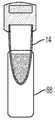
도 14 에는 본 발명의 다른 일 실시예에 따른 샘플 안정제를 구비한 용기의 사시도가 도시되어 있다.
도 15 에는 본 발명의 다른 일 실시예에 따른 샘플 안정제를 구비한 용기의 사시도가 도시되어 있다.
도 16 에는 본 발명의 다른 일 실시예에 따른 샘플 안정제를 구비한 용기의 사시도가 도시되어 있다.
도 17 에는 본 발명의 다른 일 실시예에 따른, 손가락과 결합되는 부착된 혈액 유동을 위한 장치의 횡단면도가 도시되어 있다.
도 18 에는 본 발명의 일 실시예에 따른, 부착된 혈액 유동을 위한 장치의 중공 바늘의 사시도가 도시되어 있다.
도 19 에는 본 발명의 다른 일 실시예에 따른, 부착된 혈액 유동을 위한 장치의 중공 바늘의 사시도가 도시되어 있다.
도 20 에는 본 발명의 다른 일 실시예에 따른, 부착된 혈액 유동을 위한 장치의 중공 바늘의 사시도가 도시되어 있다.
도 21 에는 본 발명의 다른 일 실시예에 따른, 부착된 혈액 유동을 위한 장치의 중공 바늘의 사시도가 도시되어 있다.
도 22 에는 본 발명의 다른 일 실시예에 따른 부착된 혈액 유동을 위한 장치의 중공 바늘의 사시도가 도시되어 있다.
도 23 에는 본 발명의 다른 일 실시예에 따른 부착된 혈액 유동을 위한 장치의 중공 바늘의 사시도가 도시되어 있다.
도 24 에는 본 발명의 다른 일 실시예에 따른 부착된 혈액 유동을 위한 장치의 중공 바늘의 사시도가 도시되어 있다.
도 25a 에는 본 발명의 일 실시예에 따른, 하우징에 연결된 용기를 구비한, 부착된 혈액 유동을 위한 장치의 용기의 사시도가 도시되어 있다.
도 25b 에는, 본 발명의 일 실시예에 따른 부착된 혈액 유동을 위한 장치의 용기의 사시도가 도시되어 있는바, 여기에는 용기가 하우징으로부터 분리되어 제1 위치에 있는 모습이 도시되어 있다.
도 25c 에는 본 발명의 일 실시예에 따른 부착된 혈액 유동을 위한 장치의 용기의 사시도가 도시되어 있는바, 여기에는 용기가 하우징으로부터 분리되어 제2 위치에 있는 모습이 도시되어 있다.
도 26a 에는 본 발명의 다른 일 실시예에 따른 부착된 혈액 유동을 위한 장치의 용기의 사시도가 도시되어 있는바, 여기에는 용기가 하우징에 연결된 모습이 도시되어 있다.
도 26b 에는 본 발명의 다른 일 실시예에 따른, 부착된 혈액 유동을 위한 장치의 용기의 사시도가 도시되어 있는바, 여기에는 용기가 하우징으로부터 분리된 모습이 도시되어 있다.
도 27a 에는 본 발명의 다른 일 실시예에 따른, 부착된 혈액 유동을 위한 장치의 용기의 사시도가 도시되어 있는바, 여기에는 용기가 하우징에 연결된 모습이 도시되어 있다.
도 27b 에는 본 발명의 다른 일 실시예에 따른, 부착된 혈액 유동을 위한 장치의 용기의 사시도가 도시되어 있는바, 여기에는 용기가 하우징으로부터 분리되어 제1 위치에 있는 모습이 도시되어 있다.
도 27c 에는 본 발명의 다른 일 실시예에 따른, 부착된 혈액 유동을 위한 장치의 용기의 사시도가 도시되어 있는바, 여기에는 용기가 하우징으로부터 분리되어 제2 위치에 있는 모습이 도시되어 있다.
도 28a 에는 본 발명의 다른 일 실시예에 따른, 부착된 혈액 유동을 위한 장치의 용기의 사시도가 도시되어 있는바, 여기에는 용기가 하우징에 연결된 모습이 도시되어 있다.
도 28b 에는 본 발명의 다른 일 실시예에 따른, 부착된 혈액 유동을 위한 장치의 용기의 사시도가 도시되어 있는바, 여기에는 용기가 하우징으로부터 분리된 모습이 도시되어 있다.
다수의 도면들에 걸쳐서, 대응되는 참조번호는 대응되는 부분을 의미한다. 여기에서 개시되는 예들은 본 발명의 예시적인 실시예일 뿐이며, 따라서 그 예들은 어떤 방식으로든 본 발명의 범위를 제한하는 것으로 추측되어서는 안 될 것이다.BRIEF DESCRIPTION OF THE DRAWINGS The above or other additional features and advantages of the present invention and methods for achieving them will be more clearly understood by reference to the following description of embodiments of the present invention with reference to the accompanying drawings.
1 shows a cross-sectional view of a device for attached blood flow according to an embodiment of the present invention.
FIG. 2 shows a state in which the device of FIG. 1 is coupled to a finger according to an embodiment of the present invention.
3 is a perspective view of a first flow guide attachment of a device for attached blood flow according to an embodiment of the present invention.
4 is a perspective view of a first flow guide attachment of a device for attached blood flow according to another embodiment of the present invention.
5 is a perspective view of a first flow guide attachment of a device for attached blood flow according to another embodiment of the present invention.
6 is a perspective view of a first flow guide attachment of a device for attached blood flow according to another embodiment of the present invention.
7A is a perspective view of a second flow guide attachment of a device for attached blood flow according to an embodiment of the present invention.
7B is a perspective view of an attached blood flow with an inner wall of a container and a second flow guide attachment, in accordance with an embodiment of the present invention.
8A is a perspective view of a second flow guide attachment of a device for attached blood flow according to another embodiment of the present invention.
8B is a perspective view of an attached blood flow with an inner wall of a container and a second flow guide attachment, according to another embodiment of the present invention.
9A is a perspective view of a second flow guide attachment of a device for attached blood flow according to another embodiment of the present invention.
9B is a perspective view of an attached blood flow with an inner wall of a container and a second flow guide attachment, according to another embodiment of the present invention.
10A is a perspective view of a second flow guide attachment of a device for attached blood flow according to another embodiment of the present invention.
10B is a perspective view of an attached blood flow having an inner wall of a container and a second flow guide attachment, according to another embodiment of the present invention.
11 is a cross-sectional view of a device for attached blood flow according to another embodiment of the present invention.
FIG. 12 shows an enlarged view of an open cell foam material, taken along
13 is a perspective view of a container having a sample stabilizer according to an embodiment of the present invention.
14 is a perspective view of a container having a sample stabilizer according to another embodiment of the present invention.
15 is a perspective view of a container having a sample stabilizer according to another embodiment of the present invention.
16 is a perspective view of a container having a sample stabilizer according to another embodiment of the present invention.
17 is a cross-sectional view of an attached blood flow device coupled with a finger, according to another embodiment of the present invention.
18 is a perspective view of a hollow needle of a device for attached blood flow, according to an embodiment of the present invention.
19 shows a perspective view of a hollow needle of a device for attached blood flow, according to another embodiment of the present invention.
20 is a perspective view of a hollow needle of an attached blood flow device, according to another embodiment of the present invention.
21 shows a perspective view of a hollow needle of a device for attached blood flow, according to another embodiment of the present invention.
22 is a perspective view of a hollow needle of an attached blood flow device according to another embodiment of the present invention.
23 is a perspective view of a hollow needle of an attached blood flow device according to another embodiment of the present invention.
24 is a perspective view of a hollow needle of an attached blood flow device according to another embodiment of the present invention.
25A is a perspective view of a vessel of an attached blood flow device having a vessel connected to a housing, according to an embodiment of the present invention.
25B is a perspective view of a container of an attached blood flow device according to an embodiment of the present invention, wherein the container is shown in a first position separated from the housing.
25C is a perspective view of a container of an attached blood flow device according to an embodiment of the present invention, wherein the container is shown in a second position separated from the housing.
26A is a perspective view of a container of an attached blood flow device according to another embodiment of the present invention, in which the container is shown connected to the housing.
26B is a perspective view of a container of an attached blood flow device according to another embodiment of the present invention, wherein the container is shown separated from the housing.
27A is a perspective view of a container of an attached blood flow device according to another embodiment of the present invention, wherein the container is connected to the housing.
27B is a perspective view of a container of an attached blood flow device according to another embodiment of the present invention, wherein the container is shown in a first position separated from the housing.
27C is a perspective view of a container of an attached blood flow device according to another embodiment of the present invention, wherein the container is shown in a second position separated from the housing.
28A is a perspective view of a container of an attached blood flow device according to another embodiment of the present invention, wherein the container is connected to the housing.
28B is a perspective view of a container of an attached blood flow device according to another embodiment of the present invention, wherein the container is shown separated from the housing.
Throughout the drawings, corresponding reference numerals refer to corresponding parts. The examples disclosed herein are merely exemplary embodiments of the present invention, and therefore, they should not be construed as limiting the scope of the present invention in any way.
아래의 설명은 본 기술분야에서 통상의 지식을 가진 자가 본 발명을 실시함에 있어 설명된 실시예들을 제작 및 이용함을 돕기 위하여 제공된 것이다. 그러나, 본 기술분야에서 통상의 지식을 가진 자는 다양한 변형예, 균등예, 변형예, 및 대안예를 용이하게 이해할 것이다. 그와 같은 변형예, 변경예, 균등예, 및 대안예들 모두는 본 발명의 취지 및 범위 내에 속하는 것으로 의도되었다.The following description is provided to help those of ordinary skill in the art make and use the described embodiments in practicing the present invention. However, those skilled in the art will readily understand various modifications, equivalents, modifications, and alternatives. All such modifications, variations, equivalents, and alternatives are intended to fall within the spirit and scope of the present invention.
아래의 설명을 위한 목적으로, "상측", "하측", "우측", "좌측", "수직", "수평", "상부", "하부", "측방향", "종방향", 및 이들의 활용예는 도면의 방위를 기준으로 하여 본 발명을 설명하기 위한 것이다. 따로 명시적으로 설명되는 경우를 제외하고는 본 발명은 대안적인 변형 및 단계의 순서를 가질 수 있다는 점이 이해되어야 할 것이다. 첨부 도면들에 도시되고 아래의 상세한 설명에서 설명되는 특정 장치 및 방법은 단지 본 발명의 예시적인 실시예에 불과하다는 것이 이해되어야 할 것이다. 따라서, 여기에서 설명되는 실시예들에 관한 특정의 치수 및 다른 물리적 특성은 본 발명을 제한하는 것으로 고려되지 말아야 할 것이다.For purposes of explanation below, “top”, “bottom”, “right”, “left”, “vertical”, “horizontal”, “top”, “bottom”, “lateral”, “longitudinal”, And their application examples are for explaining the present invention based on the orientation of the drawings. It is to be understood that the present invention may have alternative modifications and sequences of steps, except where expressly set forth otherwise. It should be understood that the specific apparatus and method shown in the accompanying drawings and described in the detailed description below are merely exemplary embodiments of the present invention. Accordingly, the specific dimensions and other physical properties of the embodiments described herein should not be considered as limiting the present invention.
본 발명의 부착된 혈액 유동을 위한 장치(10)는 수집 부위로부터 수집 용기로의 부착된 혈액 유동(attached blood flow)을 보장하는 제어된 혈액 유동 경로를 제공한다. 본 발명의 부착된 혈액 유동을 위한 장치(10)는 요망되는 방식으로 혈액 유동을 제어하기 위한 세 가지의 주요 기술 요소들을 이용함으로써 상기 유동 경로를 제공한다. 첫째, 환자의 피부 표면으로부터 수집 하우징으로 혈액 샘플을 제어 및 안내함에 있어서 제1 유동 안내 부착부를 거친다. 둘째, 수집 하우징의 제1 단부로부터 수집 하우징의 제2 단부까지 혈액 샘플을 제어 및 안내함에 있어서 모세관 전달(capillary transfer)을 거친다. 셋째, 수집 하우징의 제2 단부로부터 수집 용기의 수집 공동으로 혈액 샘플을 제어 및 안내함에 있어서 제2 유동 안내 부착부를 거친다.The
도 1 내지 도 10b 에는 본 발명의 부착된 혈액 유동을 위한 장치의 예시적인 실시예가 도시되어 있다. 도 1 내지 도 10b 를 참조하면, 본 발명의 부착된 혈액 유동을 위한 장치(10)는 수집 부위로부터 수집 용기까지 부착된 혈액 유동을 보장하는 제어된 방식의 혈액 유동 경로를 제공한다.1-10B show an exemplary embodiment of a device for attached blood flow of the present invention. 1-10B, the
통상적인 랜싯 장치를 이용하여 환자의 피부를 천공하면, 혈액이 손가락의 표면에서 퍼지고 그 표면에 남아 있게 된다. 혈액 및 혈액 유동의 제어가 없다면, 혈액은 손가락의 표면 상에 머무르고 수집 용기로 쉽게 흐르지 않을 수 있다.When a patient's skin is punctured using a conventional lancet device, blood spreads and remains on the surface of the finger. Without control of blood and blood flow, blood may stay on the surface of the finger and not flow easily into the collection vessel.
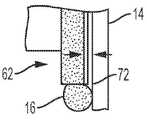
도 1 내지 도 10b 를 참조하면, 예시적인 일 실시예에서, 수집 부위로부터 수집 용기까지 혈액 샘플의 유동을 안내 및 제어하기 위하여 혈액 샘플이 부착되는 유동 안내 부착부들을 제공하는, 혈액의 부착된 유동을 위한 장치(10)는 일반적으로 하우징(12) 및 하우징(12)에 분리가능하게 연결될 수 있는 수집 용기(14)를 포함한다. 용기(14)는 수집 공동(70)을 한정하고, 내벽 또는 내벽 표면(72)을 포함한다.1-10B , in one exemplary embodiment, the attached flow of blood provides flow guide attachments to which the blood sample is attached to guide and control the flow of the blood sample from the collection site to the collection vessel.
도 1 내지 도 10b 를 참조하면, 하우징(12)은 중심선(CL)을 한정하고, 제1 단부(20), 제2 단부(22), 및 유동 채널(24)을 포함한다. 유동 채널(24)은 유입구(26) 및 유출구(28)를 포함한다. 유동 채널(24)의 일부분, 예를 들어 중간부(30)는 하우징(12)의 중심선(CL)으로부터 오프셋(offset)되어 있다. 이것은 유동 채널(24)의 유출구(28)가 수집 용기(14)의 내벽 표면(72)에 인접하게 배치됨을 보장하는바, 이에 대해서는 아래에서 상세히 설명한다. 또한 유동 채널(24)은 유입구(26)에 제1 유동 안내 부착부(32)를, 그리고 유출구(28)에 제2 유동 안내 부착부(34)를 포함한다. 일 실시예에서, 유동 채널(24)의 유출구(28)는 도 1 및 도 2 에 도시된 바와 같이 하우징(12)의 제2 단부(22)를 넘어 연장된다.1-10B , the
도 1 및 도 2 를 참조하면, 수집 용기(14)가 하우징(12)에 연결된 상태에서, 유동 채널(24)의 유출구(28)는 수집 용기(14)의 수집 공동(70)과 유체 소통되고, 유동 채널(24)의 유출구(28)는 수집 용기(14)의 내벽 표면(72)에 인접하게 배치된다.1 and 2 , with the
일 실시예에서, 하우징(12)의 제1 단부(20)는 경사 벽 표면(36)을 포함한다. 이로써, 경사 벽 표면(36)은 제1 유동 안내 부착부(32)가 상방향으로 연장됨을 가능하게 하는 출발점이 되는 물리적인 구조물, 즉 벽 표면을 제공한다. 예를 들어, 도 1 을 참조하면, 제1 유동 안내 부착부(32)는 경사 벽 표면(36)으로부터 하우징(12)의 유입구(26)으로 상방향으로 연장된다. 일 실시예에서, 경사 벽 표면(38)은 유동 채널 진입부(38)를 한정한다.In one embodiment, the
본 발명의 부착된 혈액 유동을 위한 장치(10)는 수집 부위로부터 수집 용기까지 부착된 혈액 유동을 보장하는 제어된 혈액 유동 경로를 제공한다. 본 발명의 부착된 혈액 유동을 위한 장치(10)는 요망되는 방식으로 혈액 유동을 제어하기 위한 세 가지 주요 기술 요소를 활용하여 이를 달성한다. 첫째, 환자의 피부 표면으로부터 수집 하우징으로 혈액 샘플을 제어 및 안내함에 있어서 제1 유동 안내 부착부를 거친다. 둘째, 수집 하우징의 제1 단부로부터 수집 하우징의 제2 단부까지 혈액 샘플을 제어 및 안내함에 있어서 모세관 전달(capillary transfer)을 거친다. 셋째, 수집 하우징의 제2 단부로부터 수집 용기의 수집 공동으로 혈액 샘플을 제어 및 안내함에 있어서 제2 유동 안내 부착부를 거친다.The
예를 들어 도 2 를 참조하면, 하우징(12)의 제1 단부(20)가 혈액 소스(16)와 소통되어 있는 상태에서, 제1 유동 안내 부착부(32), 유동 채널(24), 제2 유동 안내 부착부(34), 및 수집 용기(14)의 내벽 표면(72)은, 혈액(16)의 첫 방울과 후속하는 혈액(16)이 하우징(12)의 제1 단부(20)로부터 수집 용기(14)의 수집 공동(70)까지 따르는 부착된 혈액 유동을 수립하는 부착부들을 제공한다.Referring for example to FIG. 2 , with the
제1 주요 혈액 유동 경로 요소(40)는 손가락(F)의 표면(S)으로부터 멀리 그리고 수집 용기(14)를 향하는 방향으로 혈액(16)의 첫 방울을 안내한다. 일 실시예에서, 하우징(12)의 제1 단부(20)가 혈액 소스(16)와 소통되어 있는 상태에서, 제1 유동 안내 부착부(32)는 혈액(16)의 첫 방울이 부착되어 아래로 유동하고 제어된 방식으로 하우징(12)의 유동 채널(24)로 가게끔하는 필러(pillar)를 제공한다. 다시 말하면, 혈액(16)의 첫 방울은 제1 유동 안내 부착부(32)에 부착되어서 제1 유동 안내 부착부(32)로부터 유동 채널(24)로 유동한다.The first primary blood
일 실시예에서, 경사 벽 표면(36)은 제1 유동 안내 부착부(32)로부터 하우징(12)의 유동 채널(24)로의 하방향의 부착된 유동 경로를 제공한다. 혈액(16)의 첫 방울이 제1 유동 안내 부착부(32)에 부착되고 이를 따라 아래로 유동한 다음, 후속하는 혈액(16)은 하우징(12)의 제1 단부(20)로부터 수집 용기(14)의 수집 공동(70)까지 혈액(16)의 첫 방울의 상기 부착된 혈액 유동 경로를 따른다.In one embodiment, the
제2 주요 혈액 유동 경로 요소(42)는 혈액(16)을 유동 채널(24)을 따라 아래로 그리고 수집 용기(14)를 향하는 방향으로 제2 유동 안내 부착부(34)로 안내한다. 예를 들어, 혈액(16)의 첫 방울 및 후속하는 혈액(16)은 모세관 작용에 의하여 유동 채널(24)을 통해서 제2 유동 안내 부착부(34)로 당겨진다. 일 실시예에서, 유동 채널(24)은 모세관 유동 채널이다. 일 실시예에서, 유동 채널(24)은, 혈액(16)을 손가락(F)의 표면(S)로부터 멀리 유동 채널(24) 아래로 당기는 모세관 힘을 이용하는 모세관이다.The second primary blood
제3 주요 혈액 유동 경로 요소(44)는 혈액(16)을 유동 채널(24)로부터 수집 용기(14)로 안내한다. 본 발명의 장치(10)는 부착된 유동을 거쳐서 유동 채널(24)로부터 수집 용기(14)로의 이동을 보장한다. 예를 들어, 혈액(16)은 제2 유동 안내 부착부(34) 및 수집 용기(14)의 내벽 표면(72)에 부착되어서, 유동 채널(24)로부터 수집 용기(14)의 수집 공동(70) 안으로 유동한다.A third primary blood flow path element 44 guides
제3 주요 혈액 유동 경로 요소(44)가 혈액(16)을 유동 채널(24)로부터 수집 용기(14)로 안내함에 있어서, 유동 채널(24)의 일부분, 즉 중간부(30)가 하우징(12)의 중심선(CL)으로부터 오프셋되도록 하는 것이 중요하다. 이것은, 유동 채널(24)의 유출구(28) 및 제2 유동 안내 부착부(34)가 수집 용기(14)의 내벽 표면(72)에 인접하게 되게 하고, 이로써 유동 채널(24)로부터 수집 용기(14)로의 상기 부착된 혈액 유동의 전환이 보장된다.As the third primary blood flow path element 44 guides the
만일 혈액(16)이 부착될 다른 부분을 만날 수 있다면, 혈액(1)은 아래로만 그리고 유동 채널(24)로부터 수집 용기(14) 안으로만 유동할 것이다. 제2 유동 안내 부착부(34) 및 수집 용기(14)의 내벽 표면(72)은 부착된 혈액 유동을 거쳐서 혈액(16)을 수집 용기(14)의 수집 공동(70)으로 제어하기 위한 그러한 부착부를 제공한다.Blood 1 will only flow downwards and from
전술된 바와 같이 부착된 혈액 유동의 이 경로가 일단 수립되면, 후속하는 혈액(16)은 이 부착된 혈액 유동을 따라서 유동한다. 전술된 방식으로, 본 발명의 장치(10)는 하우징(12)의 제1 단부(20)로부터 수집 용기(14)의 수집 공동(70)까지 혈액(16)의 첫 방울 및 후속하는 혈액(16)이 따르게 되는 부착된 혈액 유동을 수립한다.Once this path of adherent blood flow is established as described above,
제1 유동 안내 부착부(32)는 도 3 내지 도 6 에 도시된 바와 같이 다양하게 상이한 설계안 및 구조를 가질 수 있다. 제1 유동 안내 부착부(32)의 추가적인 대안적 설계안과 구조에 대해 고찰해본다. 예를 들어 도 3 을 참조하면, 일 실시예에서 제1 유동 안내 부착부(32)는 부착 필러(50)이다. 부착 필러(50)는 가변적인 직경 및 길이를 가질 수 있는 단일의 필러 구조물이다. 부착 필러(50)는 혈액의 첫 방울을 유인하고 제2 모세관 섹션으로의 유동 경로를 수립하기 위하여, 친수성 표면 특성을 가질 수 있다. 일 실시예에서, 부착 필러(50)는 0.25 mm 내지 4 mm 사이의 직경과, 2 mm 내지 20 mm 사이의 길이를 가질 수 있다.The first
도 4 를 참조하면, 다른 일 실시예에서, 제1 유동 안내 부착부(32)는 복수의 부착 필러(52)이다. 상기 복수의 부착 필러(52)는 필러의 다양하게 상이한 갯수를 포함하여, 상이한 크기 및 구조를 갖는 필러들을 포함할 수 있다. 일 구성형태에서, 상기 복수의 부착 필러(52)는 혈액의 첫 방울이 상기 구조물의 측부를 얼룩지게 하거나 또는 요망되지 않는 위치에서 고이지 않고서 유동 경로를 수립하도록 하기 위하여 복수의 표면들을 제공할 수 있다. 또한 복수의 필러(52)들은 개별의 필러 구조물 사이에 형성되는 복수의 모세관 섹션들로 인하여 추가적인 모세관 작용을 제공하기도 한다. 일 구성형태에서, 복수의 부착 필러(52)들은 2 내지 10 개의 부착 필러, 예를 들어 5 내지 10 개의 부착 필러를 포함할 수 있다. 일 실시예에서, 각 필러는 0.25 mm 내지 4 mm 사이의 직경과 2 mm 내지 20 mm 사이의 길이를 가질 수 있다.Referring to FIG. 4 , in another embodiment, the first
도 5 를 참조하면, 다른 일 실시예에서, 제1 유동 안내 부착부(32)는 돌출형 구조물(54)이다. 돌출형 구조물(54)은 부착된 혈액 유동을 안내하는 것으로서, 다양한 형상, 크기, 및 구조를 가질 수 있다. 이 구성형태에서, 경사진 구조물은 혈액의 첫 방울이 부착되어 제2 모세관 섹션으로 안내되도록 하는 친수성 표면을 제공한다. 선택적으로, 상기 경사 구조물의 두께는 대략 0.25 내지 대략 5 mm 사이일 수 있다.Referring to FIG. 5 , in another embodiment, the first
도 6 을 참조하면, 다른 일 실시예에서, 제1 유동 안내 부착부(32)는 모세관 홈 부분(56)이다. 모세관 홈 부분(56)은 부착된 혈액 유동을 안내하는 것으로서, 상이한 형상, 크기, 및 갯수의 홈을 포함할 수 있다. 이 구성형태에서, 홈들을 구비한 필러 구조물은 홈들에서의 증가된 표면으로 인하여 상대적으로 높은 모세관 힘으로 보조하며, 이로써 혈액의 첫 방울이 손가락으로부터 신속히 이동하여 제2 모세관 채널로 전달되게 하는 모세관 채널로서 작용한다. 일 구성형태에서, 제공되는 홈들의 갯수는 1 내지 20 개 사이일 수 있고, 각 홈의 직경은 0.25 mm 내지 1 mm 사이일 수 있다.6 , in another embodiment, the first
제2 유동 안내 부착부(34)는 도 7a 내지 도 10b 에 도시된 바와 같이 다양하게 상이한 설계안 및 구조를 가질 수 있다. 제2 유동 안내 부착부(34)의 추가적으로 대안적인 설계안 및 구조가 고찰된다. 예를 들어 도 1 및 도 2 를 참조하면, 일 실시예에서는 제2 유동 안내 부착부(34)가 부착 립(attachment lip)(60)이다. 부착 립(60)은 전술된 바와 같이 수집 용기(14)의 수집 공동(70) 안으로의 부착된 혈액 유동을 수립하도록 설계된 립이다. 부착 립(60)은 혈액이 확장하고 액적을 형성하여 수집 공동에 대한 부착을 수립하게 하는 표면을 제공한다.The second
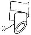
도 7a 및 도 7b 를 참조하면, 다른 일 실시예에서는 제2 유동 안내 부착부(34)가 연장된 모세관 부분(62)이다. 일 구성형태에서, 상기 연장된 모세관 부분(62)은 유동 채널(24)을 넘어 2 mm 내지 10 mm 사이만큼 연장될 수 있다. 상기 연장된 모세관 부분(62)은 1 mm 미만의 거리를 두고 수집 용기의 벽으로부터 이격될 수 있다.7A and 7B , in another embodiment, the second
도 8a 및 도 8b 를 참조하면, 다른 일 실시예에서는 제2 유동 안내 부착부(34)가 내향 만곡 립(inward curved lip)(64)이다. 상기 내향 만곡 립 구조는 혈액이 하우징의 일부분으로부터 수집 공동의 표면으로 부착되게 하는데 도움을 준다. 일 구성형태에서, 상기 내향 만곡 립 구조는 대략 0.5 내지 대략 10 mm 만큼 유동 채널(24)을 넘어 연장될 수 있다.8A and 8B , in another embodiment the second
도 9a 및 도 9b 를 참조하면, 다른 일 실시예에서 제2 유동 안내 부착부(34)는 평면 절단 립(planar cut lip)(66)이다. 상기 평면 절단 립(66)도 혈액 액적의 형성 및 수집 공동의 표면에 대한 혈액의 부착을 돕는다. 일 구성형태에서, 상기 평면 절단 립은 대략 10° 내지 대략 80° 사이의 각도를 가질 수 있다.9A and 9B , in another embodiment the second
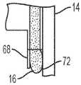
도 10a 및 도 10b 를 참조하면, 다른 일 실시예에서는 제2 유동 안내 부착부(34)가 연장된 필러 구조물(68)이다. 일 구성형태에서, 상기 연장된 필러 구조물은 대략 0.5 mm 내지 대략 10 mm의 거리만큼 유동 채널(24)을 넘어 연장될 수 있다.10A and 10B , in another embodiment, the second
도 1, 2, 17, 및 25a 내지 28b 를 참조하면, 본 발명의 수집 용기(14)의 예시적인 실시예들이 도시되어 있다. 수집 용기(14)의 추가적으로 대안적인 설계안 및 구조가 고찰된다. 본 발명의 수집 용기(14)는 하우징(12)에 분리가능하게 연결될 수 있다. 수집 용기(14)는 수집 공동(70)을 한정하고, 내벽 또는 내벽 표면(72)을 포함한다. 도 1 및 도 2 를 참조하면, 수집 용기(14)가 하우징(12)에 연결된 상태에서, 유동 채널(24)의 유출구(28)는 수집 용기(14)의 수집 공동(70)과 유체 소통되고, 유동 채널(24)의 유출구(28)는 수집 용기(14)의 내벽 표면(72)에 인접하게 위치한다. 일 구성형태에서, 유동 채널(24)의 내경은 대략 0.5 mm 내지 대략 2 mm 사이일 수 있다.1, 2, 17, and 25A-28B, exemplary embodiments of a
도 25a 내지 도 25c 를 참조하면, 일 실시예에서 수집 용기(14)는 분리가능하게 연결될 수 있는 캡(cap)(74) 및 테더 요소(tether element)(76)를 포함한다. 이와 같은 실시예에서, 수집 용기(14)가 도 25a 에 도시된 바와 같이 하우징(12)에 연결된 때에 캡(74)은 분리된다. 테더 요소(76)는, 도 25b 에 도시된 바와 같이 캡(74)이 수집 용기(14)의 개방된 상부 단부(78)로부터 분리된 상태에서 캡(74)이 수집 용기(14)의 일부분에 여전히 확보된채로 유지됨을 보장한다. 수집 용기(14) 내에 요망되는 양의 혈액(16)이 수집된 다음에는, 수집 용기(14)가 하우징(12)으로부터 분리되고, 캡(74)이 수집 용기(14)에 연결되어서, 도 25c 에 도시된 바와 같이 혈액(16)을 수집 용기(14) 내에 보호되게 밀봉한다.25A-25C , in one embodiment the
도 26a 내지 도 26b 를 참조하면, 일 실시에에서는 수집 용기(14)가 재밀봉가능한(resealable) 격막(80)을 포함한다. 이와 같은 실시예에서는 수집 용기(14)가 하우징(12)에 연결된 상태에서, 유동 채널(24)의 일부분이 격막(80)을 관통하여, 유동 채널(24)이 수집 용기(14)의 수집 공동(70)과 유체 소통된다. 수집 용기(14) 내에 요망되는 양의 혈액(16)이 수집된 다음에는, 수집 용기(14)가 하우징(12)으로부터 분리되고, 격막(80)은 도 26b 에 도시된 바와 같이 수집 용기(14) 내에 혈액(16)을 보호되게 밀봉하도록 폐쇄된 밀봉 위치로 복귀하여 자동적으로 재밀봉한다.26A-26B , in one embodiment, the
도 27a 내지 도 27c 를 참조하면, 일 실시예에서는 수집 용기(14)가 변형가능 토출부(82)를 포함한다. 이와 같은 실시예에서, 수집 용기(14)가 하우징(12)으로부터 분리된 상태에서, 혈액(16)의 일부분이 변형가능 토출부(82)의 작동에 의하여 수집 용기(14)로부터 토출될 수 있다. 예를 들어, 변형가능 토출부(82)는 초기 위치(도 27a 및 도 27b)와 변형 위치(도 27c) 간으로 전환될 수 있는바, 초기 위치에서는 혈액(16)이 수집 공동(70) 안에 수납되고, 변형 위치에서는 혈액(1)의 일부분이 수집 용기(14)의 수집 공동(70)으로부터 배출된다. 변형가능 토출부(82)는 상기 초기 위치(도 27a 및 도 27b)로부터 변형 위치(도 27c)로의 전환을 위하여 압박된다. 이와 같은 방식으로, 혈액(16)은 예를 들어 포인트-오브-케어 테스트 기기, 카트리지 테스터, 또는 환자 근처의 테스트 기기와 같은 샘플의 분석을 위한 장치로 전달될 수 있으면서도, 의료 실무자가 혈액 샘플에 노출됨은 최소화된다. 일 실시예에서, 수집 용기(14)는 수집 용기(14)의 배출부(86)를 안전하게 밀봉하는 단부 캡(84)을 더 포함한다. 사용자가 수집 용기(14)로부터 혈액(16)의 일부분을 배출시킬 준비가 된 때, 혈액(16)을 토출시키기 전에 단부 캡(84)이 수집 용기(14)의 배출부(86)로부터 분리된다.27A-27C , in one embodiment, the
도 28a 및 도 28b 를 참조하면, 일 실시예에서는 수집 용기(14)가 연장 튜브(88)를 포함한다. 연장 튜브(88)는 분석자 및 분석 기기들과 호환가능한 것이다.28A and 28B , in one embodiment, the
도 17 내지 도 24 에는 본 발명의 부착된 혈액 유동을 위한 장치의 다른 일 예시적인 실시예가 도시되어 있다. 도 17 내지 도 24 를 참조하면, 본 발명의 부착된 혈액 유동을 위한 장치(100)는, 수집 부위로부터 수집 용기까지의 부착된 혈액 유동을 보장하는 제어된 혈액 유동 경로를 제공한다.17 to 24 show another exemplary embodiment of the device for attached blood flow of the present invention. 17-24, the
랜싯 장치를 이용하여 환자의 피부를 천공한 때, 혈액은 손가락의 표면 상에서 퍼지고 그 표면 상에 머무를 것이다. 혈액 및 혈액 유동을 제어하지 않는다면, 그 혈액은 손가락의 표면 상에 머물러서 수집 용기로 유동하지 않을 것이다.When a lancet device is used to puncture a patient's skin, blood will spread and stay on the surface of the finger. If the blood and blood flow are not controlled, the blood will stay on the surface of the finger and will not flow into the collection vessel.
도 17 내지 도 24 를 참조하면, 예시적인 일 실시예에서, 부착된 혈액 유동을 위한 장치(100)는 일반적으로 하우징(112) 및 하우징(112)에 분리가능하게 연결될 수 있는 수집 용기(14)을 포함한다. 수집 용기(14)는 수집 공동(70)을 한정하고, 내벽 또는 내벽 표면(72)을 포함한다. 도 1 내지 도 10b 를 참조하여 위에서 설명된 장치(10)와 호환가능한 동일한 수집 용기(14)는 도 17 내지 도 24 를 참조로 하여 설명되는 장치(100)와 호환가능하다.17-24 , in one exemplary embodiment, the attached
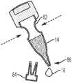
도 17 을 참조하면, 하우징(112)은 중심선(CL)을 한정하고, 제1 단부(120), 제2 단부(122), 중공 바늘(123), 및 유동 채널(124)을 포함한다. 유동 채널(24)은 유입구(126) 및 유출구(128)를 포함한다. 유동 채널(124)의 일부분, 예를 들어 저부 부분(130)은 하우징(112)의 중심선(CL)으로부터 오프셋되어 있다. 이것은, 유동 채널(124)의 유출구(128)이 수집 용기(14)의 내벽 표면(72)에 인접하게 배치됨을 보장하는바, 이에 대해서는 아래에서 상세히 설명한다. 또한 유동 채널(124)은 유출구(128)에서 유동 안내 부착부(134)를 포함한다. 일 실시예에서, 유동 채널(124)의 유출구(128)는 도 17 에 도시된 바와 같이 하우징(112)의 제2 단부(122)를 넘어 연장된다. 일 실시예에서, 중공 바늘(123)은 하우징(112)이 제1 단부(120)와 유동 채널(124) 사이에 위치한다.Referring to FIG. 17 , the
도 17 내지 도 24 에 도시된 실시예에서, 중공 바늘(123)은 도 1 내지 도 10b 를 참조하여 위에서 설명된 장치(10)의 제1 유동 안내 부착부(32)와 유사한 기능을 수행한다.17-24 , the
도 17 을 참조하면, 수집 용기(14)가 하우징(112)에 연결된 상태에서, 유동 채널(124)의 유출구(128)는 수집 용기(14)의 수집 공동(70)과 유체 소통되고, 유동 채널(124)의 유출구(128)는 수집 용기(14)의 내벽 표면(72)에 인접하게 위치한다.Referring to FIG. 17 , with the
랜싯 장치를 이용하여 환자의 피부를 천공한 때, 혈액은 손가락의 표면 상에서 퍼지고 그 표면 상에 머무를 것이다. 혈액 및 혈액 유동을 제어하지 않는다면, 그 혈액은 손가락의 표면 상에 머무를 뿐이고 수집 용기로 유동하지 않을 것이다.When a lancet device is used to puncture a patient's skin, blood will spread and stay on the surface of the finger. If the blood and blood flow are not controlled, the blood will only stay on the surface of the finger and will not flow into the collection vessel.
본 발명의 부착된 혈액 유동을 위한 장치(100)는 수집 부위로부터 수집 용기까지의 부착된 혈액 유동을 보장하는 제어된 혈액 유동 경로를 제공한다. 본 발명의 부착된 혈액 유동을 위한 장치(100)는 혈액 유동을 요망되는 방식으로 제어하기 위한 세 가지의 주요 기술 요소를 이용하여 이를 달성한다.The
예를 들어 도 17 을 참조하면, 하우징(112)의 제1 단부(120)가 혈액 소스(16)와 소통된 상태에서, 중공 바늘(123), 유동 채널(124), 유동 안내 부착부(134), 및 수집 용기(14)의 내벽 표면(72)은 혈액(16)의 첫 방울 및 후속하는 혈액(16)이 하우징(112)의 제1 단부(120)로부터 수집 용기(14)의 수집 공동(70)까지 이동함에 있어서 따르는 부착된 혈액 유동을 수립하는 부착부들을 제공한다.For example, referring to FIG. 17 , with the
제1 주요 혈액 유동 경로 요소(140)는 손가락(F)의 표면(S)으로부터 멀리 그리고 수집 용기(14)를 향하는 방향으로 혈액(16)의 첫 방울을 안내한다. 일 실시예에서, 하우징(112)의 제1 단부(120)가 혈액 소스(16)와 소통되어 있는 상태에서, 혈액(16)의 첫 방울은 중공 바늘(123)의 일부분에 부착되어서, 도 17 에 도시된 바와 같이 중공 바늘(123)을 통하여 유동 채널(124)까지 제어된 방식으로 유동한다.The first primary blood
이와 같은 방식으로, 중공 바늘(123)의 일부분은 도 1 내지 도 10b 에 도시된 장치(10)에 관하여 전술된 제1 유동 안내 부착부(32)와 유사한 기능을 수행하는 부착부를 제공한다. 중공 바늘(123)을 포함하는 본 발명의 장치(100)는, 중공 바늘(123)이, 혈액 소스(16)를 제공하기 위하여 손가락(F)의 피부 표면(S)을 랜싱하기 위하여 이용될 수도 있다는 장점을 제공한다. 이와 같은 실시예에서는, 별도의 랜싯 장치가 필요하지 않다. 예를 들어 일 실시예에서, 중공 바늘(123)은 혈액 소스(16)를 제공하기 위하여 손가락(F)의 피부 표면(S)을 랜싱하기 위해 사용될 수 있는 랜싱 블레이드(lancing blade)(151)를 포함할 수 있다. 이와 같은 실시예에서는 하우징(112)의 제1 단부(120)가 혈액 소스(16)와 소통된 상태에서, 혈액(16)의 첫 방울 및 후속하는 혈액(16)이 랜싱 블레이드(151)에 부착되고 중공 바늘(123)을 통하여 유동 채널(124)로 유동한다.In this way, a portion of the
혈액(16)의 첫 방울이 중공 바늘(123)의 일부분에 부착되어 중공 바늘(123)을 통하여 유동한 이후, 후속하는 혈액(16)이 혈액(16)의 첫 방울의 상기 부착된 혈액 유동 경로를 따라서 하우징(12)의 제1 단부(120)로부터 수집 용기(14)의 수집 공동(70)으로 이동한다.After the first drop of
제2 주요 혈액 유동 경로 요소(142)는 모세관 작용에 의하여 혈액(16)을 유동 채널(124)을 통해서 유동 안내 부착부(134)로 당기거나 또는 안내한다. 일 실시예에서, 제2 주요 혈액 유동 경로 요소(142)는 모세관 작용에 의하여 혈액(16)을 중공 바늘(123) 및 유동 채널(124)을 통해서 유동 안내 부착부(134)로 당기거나 또는 안내한다. 예를 들어, 혈액(16)의 첫 방울 및 후속하는 혈액(16)은 모세관 작용에 의하여 유동 채널(124)을 통해서 유동 안내 부착부(134)로 당겨진다. 일 실시예에서, 유동 채널(124)은 모세관 유동 채널이다. 일 실시예에서, 유동 채널(124)은, 혈액(16)을 손가락(F)의 표면(S)으로부터 멀리 그리고 유동 채널(124) 아래로 당기기 위하여 모세관 힘을 이용하는 모세관이다.The second primary blood
일 실시예에서, 하우징(112)은 중공 바늘(123)과 유동 채널(124) 사이에 있는 경사 벽 표면(136)을 포함한다. 일 실시예에서, 경사 벽 표면(138)은 유동 채널 진입부(138)를 한정한다. 일 실시예에서, 경사 벽 표면(136)은 중공 바늘(123)로부터 하우징(112)의 유동 채널(124)까지의 하방향의 부착된 유동 경로를 제공한다.In one embodiment, the
제3 주요 혈액 유동 경로 요소(144)는 유동 채널(124)로부터 수집 용기(14) 안으로 혈액(16)을 안내한다. 본 발명의 장치(100)는, 부착된 유동을 통하여 유동 채널(124)로부터 수집 용기(14)로의 이동을 보장한다. 예를 들어, 혈액(16)은 유동 안내 부착부(134) 및 수집 용기(14)의 내벽 표면(72)에 부착되어, 유동 채널(124)로부터 수집 용기(14)의 수집 공동(70) 안으로 유동한다.A third primary blood
제3 주요 혈액 유동 경로 요소(144)가 유동 채널(124)로부터 수집 용기(14) 안으로 혈액(16)을 안내함에 있어서, 유동 채널(124)의 일부분, 예를 들어 저부(130)가 하우징(112)의 중심선(CL)으로부터 오프셋되도록 하는 것이 중요하다. 이것은, 유동 채널(124)의 유출구(128) 및 유동 안내 부착부(134)가 수집 용기(14)의 내벽 표면(72)에 인접하게 위치하게 됨을 보장하고, 이로써 상기 부착된 혈액 유동이 유동 채널(124)로부터 수집 용기(14)로 전환됨이 보장된다.In guiding the
혈액(16)이 부착될 다른 부분을 만날 수 있다면, 혈액(16)은 하방향으로 유동 채널(124)로부터 나와서 수집 용기(14)로만 유동할 것이다. 유동 안내 부착부(134) 및 수집 용기(14)의 내벽 표면(72)은, 혈액(16)을 부착된 혈액 유동을 통하여 수집 용기(14)의 수집 공동(70)으로 제어하기 위해서 그와 같은 부착부들을 제공한다.If the
전술된 바와 같이, 부착된 혈액 유동의 상기 경로가 수립된 다음에는 후속하는 혈액(16)이 뒤따르고 상기 부착된 혈액 유동을 따라 유동한다. 전술된 방식으로, 본 발명의 장치(100)는 하우징(112)의 제1 단부(120)로부터 수집 용기(14)의 수집 공동(70)까지 혈액(16)의 첫 방울 및 후속하는 혈액(16)이 따르는 부착된 혈액 유동을 수립한다.As described above, once the path of adherent blood flow has been established,
전술된 바와 같이, 혈액(16)을 위한 부착부를 제공하는 중공 바늘(123)의 일부분은 도 1 내지 도 10b 에 도시된 장치(10)에 관하여 전술된 제1 유동 안내 부착부(32)와 유사한 기능을 수행한다.As noted above, the portion of the
중공 바늘(123)은 도 18 내지 도 24 에 도시된 바와 같이 다양하게 상이한 설계안 및 구조를 가질 수 있다. 중공 바늘(123)의 추가적으로 대안적인 설계안 및 구조가 고찰된다. 예를 들어 도 18 및 도 19 를 참조하면, 일 실시예에서 중공 바늘(123)은 경사 절단 중공 바늘을 포함한다. 일 구성형태에서, 상기 경사 절단 중공 바늘의 경사부는 3 mm 내지 6 mm 사이의 길이를 가질 수 있으며, 루멘 내경(lumen inner diameter)은 0.25 mm 내지 4 mm 사이일 수 있다.The
전술된 바와 같이, 도 20 및 도 21 을 참조하면, 일 실시예에서는 중공 바늘(123)이 혈액 소스(16)를 제공하기 위하여 손가락(F)의 피부 표면(S)을 랜싱하기 위하여 이용될 수 있는 랜싱 블레이드(151)를 포함할 수 있다.20 and 21 , in one embodiment a
도 21 을 참조하면, 다른 일 실시예에서는, 중공 바늘(123)이 중공 바늘(123) 둘레에 유동 안내 링(155)을 포함한다. 유동 안내 링(155)은 혈액(16)이 중공 바늘(123) 아래로 유동함을 방지하고, 또한 혈액(16)이 중공 바늘(123)을 통해서 유동 채널(124)로 유동함을 보장한다. 도 22 내지 도 24 에는 중공 바늘(123)의 추가적으로 대안적인 설계안 및 구조가 도시되어 있다. 바늘의 경사부는 도 3 을 참조하여 전술된 바와 같이 필러 구조 부분(32)과 유사하게, 추가적인 제1 유동 안내 부착부로서의 역할을 수행한다.Referring to FIG. 21 , in another embodiment, the
유동 안내 부착부(134)는 도 7a 내지 도 10b 에 도시된 바와 같이 다양하게 상이한 설계안 및 구조를 포함할 수 있다. 유동 안내 부착부(134)의 추가적으로 대안적인 설계안 및 구조가 고찰된다. 장치(100)의 유동 안내 부착부(134)는 도 7a 내지 도 10b 에 도시되고 전술된 장치(10)의 제2 유동 안내 부착부(34)와 동일한 설계안 및 구조를 가질 수 있다.The
본 발명의 장치(10, 100)의 다른 장점은, 장치(10, 100)가 혈액 샘플(16) 내에 샘플 안정제(200)의 배분된 혼합을 수행할 수 있다는 것이다. 도 11 및 도 12 를 참조하면, 일 실시예에서, 샘플 안정제(200)는 유동 채널(24, 124)의 일부분 내에 배치되어서, 혈액 샘플(16)이 수집 부위로부터 본 발명의 수집 용기로의 제어된 부착된 혈액 유동을 따라 이동함에 따라서 혈액 샘플(16)은 샘플 안정제(200)를 경유하여 지나갈 것이다. 이와 같은 방식으로, 혈액 샘플(16)은 장치(10, 100)의 일부분 안에 제공되어 있는 항응고제와 같은 샘플 안정제(200) 또는 다른 첨가제와 혼합될 수 있다. 샘플 안정제(200)는 항응고제, 또는 예를 들어 RNA, 단백질 전해질, 또는 다른 요소와 같이 혈액 내의 특정 요소를 보존하도록 설계된 물질일 수 있다.Another advantage of the
도 11 및 도 12 를 참조하면, 일 실시예에서 샘플 안정제(200)는 구멍(204)들을 포함하는 재료(202)와, 상기 재료(202)의 구멍(204)들 안에 있는 건조 항응고제 분말(206)을 포함할 수 있다. 이와 같은 방식으로, 상기 장치(10, 100)는 유동 채널(24, 124)의 일부분 안에 또는 그 일부분 상에 퇴적된 헤파린(Heparin) 또는 EDTA와 같은 건조 항응고제를 포함할 수 있다. 일 실시예에서, 재료(202)는 개방 셀 발포체인데, 이것은 항응고제의 통과유동 혼합 및 흡수의 효과를 증진하기 위하여 개방 셀 발포체의 셀들 안에 분산된 건조 항응고제를 포함한다. 일 실시예에서, 샘플 안정제(200)는 건조 항응고제 분말(206)이다.11 and 12 , in one embodiment, the
일 실시예에서, 상기 개방 셀 발포체는 개방 셀 발포체의 구멍(204)들에 걸쳐서 잘 분포된 건조 항응고제 분말(206)을 형성하기 위해서 항응고제에 의한 처리를 받을 수 있다. 혈액 샘플(16)이 유동 채널(24, 124)를 통해 유동함에 따라서, 혈액 샘플(16)은 개방 셀 발포체를 통과하고, 개방 셀 발포체의 내부 구멍 구조에 걸쳐 존재하는 항응고제 분말(206)에 노출된다. 이와 같은 방식으로, 혈액 심플(16)은 개방 셀 발포체 또는 재료(202)을 통과하면서 건조 항응고제 분말(206)과 혼합 및 용해된다.In one embodiment, the open cell foam may be subjected to treatment with an anticoagulant to form a dry
상기 개방 셀 발포체는 혈액에 대해 반응하지 않는 부드럽고 변형가능한 개방 셀 발포체일 수 있는바, 예를 들면 바스프(BASF)로부터 상업적으로 입수가능한 바소텍트(Basotect®)와 같은 멜라민 발포체(melamine foam)이거나, 또는 포름알데이드-멜라민-소듐 바이설파이트 코폴리머(formaldehyde-melamine-sodium bisulfite copolymer)로 이루어진 것일 수 있다. 또한 개방 셀 발포체는 열 및 유기 용제에 대해 실질적인 저항성을 가진, 유연하고 친수성이 있는 개방 셀 발포체일 수 있다. 일 실시예에서, 상기 발포체는 스폰지 재료를 포함할 수 있다.The open cell foam may be a soft, deformable open cell foam that does not react to blood, for example a melamine foam such as Basotect® commercially available from BASF, Alternatively, it may be formed of a formaldehyde-melamine-sodium bisulfite copolymer. The open cell foam may also be a flexible, hydrophilic open cell foam with substantial resistance to heat and organic solvents. In one embodiment, the foam may comprise a sponge material.
상기 항응고제 또는 다른 첨가제는 물과 첨가제의 액체 용액 안에서 발포체를 적심으로써 개방 셀 발포체 안으로 도입되고 후속하여 물을 증발시킴으로써, 발포체의 내부 구조에 걸쳐서 잘 배분된 건조 첨가제 분말이 형성될 수 있다.The anticoagulant or other additive may be introduced into an open cell foam by wetting the foam in a liquid solution of water and additives followed by evaporation of the water to form a dry additive powder well distributed throughout the internal structure of the foam.
도 13 내지 도 16 에는 샘플 안정제(200)가 수집 용기(14) 내부에 포함되어 있는 예시적인 실시예들이 도시되어 있다.13-16 illustrate exemplary embodiments in which a
예를 들어 도 13 을 참조하면, 일 실시예에서는 항응고제의 동결건조 구체(210)들이 수집 용기(14)의 수집 공동(70) 내부에 제공된다. 혈액(16)이 본 발명의 부착된 유동을 따라서 수집 용기(14) 안으로 진행함에 따라서, 항응고제 동결건조 구체(210)들은 혈액(16)과의 접촉시 혈액(16) 안에서 용해된다.For example, referring to FIG. 13 , in one embodiment lyophilized
도 14 를 참조하면, 다른 일 실시예에서 샘플 안정제(200)는 항응고제가 코팅된, 부유하는 개방 셀 발포 재료(220)를 포함한다. 도 15 를 참조하면, 다른 일 실시예에서는, 샘플 안정제(200)가 항응고제로 코팅된 부유 볼(floating ball)(230)을 포함한다. 도 16 을 참조하면, 다른 일 실시예에서는 용기(4)가 항응고제로 코팅된 벽 표면(240) 및 혼합 볼(mixing ball)(242)을 포함한다.Referring to FIG. 14 , in another embodiment, the
본원에는 예시적인 설계안을 가진 실시예를 중심으로 하여 설명되었으나, 본 발명은 본 발명의 취지 및 범위 내에서 달리 변형될 수도 있다. 따라서 본 출원은 본 발명의 일반적인 원리를 이용하는 임의의 변형, 이용, 적합화를 포괄하도록 의도된 것이다. 또한 본 출원은 본 발명이 속하는 기술분야에서의 공지 또는 공용 사항 내의 범위 내에 속하거나 또는 첨부된 청구범위의 기재 범위 내에 속하는 변형을 포괄하도록 의도되었다.Although the present application has been mainly described with reference to an embodiment having an exemplary design, the present invention may be otherwise modified within the spirit and scope of the present invention. Accordingly, this application is intended to cover any modifications, uses, and adaptations utilizing the general principles of the present invention. Also, this application is intended to cover modifications that fall within the scope of known or public matters in the art to which this invention pertains, or that fall within the scope of the appended claims.
Claims (18)
Translated fromKorean중심선을 한정하는 하우징(housing)으로서, 상기 하우징은 유입구 및 유출구를 구비한 유동 채널(flow channel), 제1 단부, 및 제2 단부를 포함하고, 상기 유동 채널의 일부분은 하우징의 중심선으로부터 오프셋(offset)되어 있으며, 상기 유동 채널은 상기 유입구에 인접한 제1 유동 안내 부착부(first flow directing attachment portion)를 포함하는, 하우징; 및
상기 하우징에 분리가능하게 연결될 수 있는 용기로서, 상기 용기는 수집 공동을 한정하고 내벽을 구비하는, 용기;를 포함하고,
상기 용기가 하우징에 연결된 때에, 상기 유동 채널의 유출구는 상기 용기의 수집 공동과 유체 소통되는, 부착된 혈액 유동을 위한 장치.A device for adherent blood flow, the device comprising:
A housing defining a centerline, the housing comprising a flow channel having an inlet and an outlet, a first end, and a second end, a portion of the flow channel offset from the centerline of the housing ( offset, wherein the flow channel includes a first flow directing attachment portion adjacent the inlet; and
a container detachably connectable to the housing, the container defining a collection cavity and having an inner wall;
and an outlet of the flow channel is in fluid communication with a collection cavity of the vessel when the vessel is connected to the housing.
상기 제1 유동 안내 부착부는, 피부 표면으로부터 상기 하우징의 일부분으로의 혈액 유동을 제어하기 위하여 혈액이 부착되는 제1 유체 부착점(first fluid attachment point)을 제공하는, 부착된 혈액 유동을 위한 장치.According to claim 1,
wherein the first flow guide attachment provides a first fluid attachment point to which blood is attached to control blood flow from a skin surface to a portion of the housing.
상기 유출구에 인접한 제2 유동 안내 부착부를 더 포함하는, 부착된 혈액 유동을 위한 장치.According to claim 1,
and a second flow guide attachment adjacent the outlet.
상기 제2 유동 안내 부착부는, 상기 하우징의 일부분으로부터 상기 용기의 수집 공동으로의 혈액 유동을 제어하기 위하여 혈액이 부착되는 제2 유체 부착점을 제공하는, 부착된 혈액 유동을 위한 장치.4. The method of claim 3,
wherein the second flow guide attachment provides a second fluid attachment point to which blood is attached to control blood flow from a portion of the housing to a collection cavity of the container.
상기 하우징의 제1 단부가 혈액 소스(source of blood)와 소통되는 때에, 상기 제1 유동 안내 부착부, 유동 채널, 제2 유동 안내 부착부, 및 용기의 내벽은, 혈액의 첫 방울 및 뒤따르는 후속 혈액의 상기 하우징의 제1 단부로부터 상기 용기의 수집 공동으로의 부착된 혈액 유동을 수립하는 부착부들을 제공하는, 부착된 혈액 유동을 위한 장치.4. The method of claim 3,
When the first end of the housing is in communication with a source of blood, the first flow guiding attachment, the flow channel, the second flow guiding attachment, and the inner wall of the container are configured to allow the first drop of blood and subsequent and providing attachments for establishing attached blood flow from the first end of the housing to the collection cavity of the container for subsequent blood.
상기 유동 채널의 유입구가 혈액 소스와 소통되는 때에, 혈액은 제1 유동 안내 부착부에 유체식으로(fluidly) 부착되어서 제1 유동 안내 부착부로부터 유동 채널로 유동하는, 부착된 혈액 유동을 위한 장치.4. The method of claim 3,
when the inlet of the flow channel is in communication with the blood source, blood is fluidly attached to the first flow guide attachment and flows from the first flow guide attachment to the flow channel. .
혈액은 후속적으로, 모세관 작용에 의해서 유동 채널을 통해 제2 유동 안내 부착부로 당겨지는, 부착된 혈액 유동을 위한 장치.8. The method of claim 7,
and the blood is subsequently drawn through the flow channel to the second flow guide attachment by capillary action.
혈액은 제2 유동 안내 부착부 및 상기 용기의 내벽에 유체식으로 부착되어서, 상기 유동 채널로부터 상기 용기의 수집 공동 안으로 유동하는, 부착된 혈액 유동을 위한 장치.9. The method of claim 8,
wherein blood is fluidly attached to the second flow guide attachment and to the inner wall of the vessel such that blood flows from the flow channel into the collection cavity of the vessel.
상기 하우징의 제1 단부는 경사 벽 표면을 포함하고, 제1 유동 안내 부착부는 상기 경사 벽 표면으로부터 연장되며, 상기 경사 벽 표면은 유동 채널 진입부를 한정하는, 부착된 혈액 유동을 위한 장치.According to claim 1,
wherein the first end of the housing includes a sloped wall surface, and a first flow guide attachment extends from the sloped wall surface, the sloped wall surface defining a flow channel entry.
상기 제1 유동 안내 부착부는 부착 필러(attachment pillar)인, 부착된 혈액 유동을 위한 장치.According to claim 1,
wherein the first flow guide attachment is an attachment pillar.
상기 제1 유동 안내 부착부는 복수의 부착 필러들을 포함하는, 부착된 혈액 유동을 위한 장치.According to claim 1,
and the first flow guide attachment comprises a plurality of attachment fillers.
상기 제2 유동 안내 부착부는 부착 립(attachment lip)인, 부착된 혈액 유동을 위한 장치.4. The method of claim 3,
wherein the second flow guide attachment is an attachment lip.
상기 제2 유동 안내 부착부는 연장된 모세관 부분인, 부착된 혈액 유동을 위한 장치.4. The method of claim 3,
and the second flow guide attachment is an elongated capillary portion.
상기 제2 유동 안내 부착부는 내향 만곡 립(inward curved lip)인, 부착된 혈액 유동을 위한 장치.4. The method of claim 3,
wherein the second flow guide attachment is an inward curved lip.
상기 제2 유동 안내 부착부는 평면 절단 립(planar cut lip)인, 부착된 혈액 유동을 위한 장치.4. The method of claim 3,
wherein the second flow guide attachment is a planar cut lip.
상기 제2 유동 안내 부착부는 연장된 필러 구조물(extended pillar structure)인, 부착된 혈액 유동을 위한 장치.4. The method of claim 3,
and the second flow guide attachment is an extended pillar structure.
상기 유동 채널의 유출구는 상기 하우징의 제2 단부를 넘어 연장되는, 부착된 혈액 유동을 위한 장치.According to claim 1,
and the outlet of the flow channel extends beyond the second end of the housing.
Applications Claiming Priority (4)
| Application Number | Priority Date | Filing Date | Title |
|---|---|---|---|
| US201662378971P | 2016-08-24 | 2016-08-24 | |
| US62/378,971 | 2016-08-24 | ||
| PCT/US2017/048147WO2018039307A1 (en) | 2016-08-24 | 2017-08-23 | A device for the attached flow of blood |
| KR1020197008624AKR102349711B1 (en) | 2016-08-24 | 2017-08-23 | device for attached blood flow |
Related Parent Applications (1)
| Application Number | Title | Priority Date | Filing Date |
|---|---|---|---|
| KR1020197008624ADivisionKR102349711B1 (en) | 2016-08-24 | 2017-08-23 | device for attached blood flow |
Publications (2)
| Publication Number | Publication Date |
|---|---|
| KR20220010056A KR20220010056A (en) | 2022-01-25 |
| KR102458200B1true KR102458200B1 (en) | 2022-10-25 |
Family
ID=59746370
Family Applications (4)
| Application Number | Title | Priority Date | Filing Date |
|---|---|---|---|
| KR1020227000413AActiveKR102460682B1 (en) | 2016-08-24 | 2017-08-23 | A device for obtaining a blood sample |
| KR1020197008604AActiveKR102349487B1 (en) | 2016-08-24 | 2017-08-23 | device for obtaining a blood sample |
| KR1020227000450AActiveKR102458200B1 (en) | 2016-08-24 | 2017-08-23 | A device for the attached flow of blood |
| KR1020197008624AActiveKR102349711B1 (en) | 2016-08-24 | 2017-08-23 | device for attached blood flow |
Family Applications Before (2)
| Application Number | Title | Priority Date | Filing Date |
|---|---|---|---|
| KR1020227000413AActiveKR102460682B1 (en) | 2016-08-24 | 2017-08-23 | A device for obtaining a blood sample |
| KR1020197008604AActiveKR102349487B1 (en) | 2016-08-24 | 2017-08-23 | device for obtaining a blood sample |
Family Applications After (1)
| Application Number | Title | Priority Date | Filing Date |
|---|---|---|---|
| KR1020197008624AActiveKR102349711B1 (en) | 2016-08-24 | 2017-08-23 | device for attached blood flow |
Country Status (13)
| Country | Link |
|---|---|
| US (5) | US11771352B2 (en) |
| EP (7) | EP3503806B1 (en) |
| JP (8) | JP7104026B2 (en) |
| KR (4) | KR102460682B1 (en) |
| CN (4) | CN115192014B (en) |
| AU (4) | AU2017315323B2 (en) |
| BR (2) | BR112019003638A2 (en) |
| CA (2) | CA3034842A1 (en) |
| ES (4) | ES2834078T3 (en) |
| MX (4) | MX2019002218A (en) |
| PL (1) | PL3503807T3 (en) |
| RU (4) | RU2747438C2 (en) |
| WO (2) | WO2018039305A1 (en) |
Families Citing this family (34)
| Publication number | Priority date | Publication date | Assignee | Title |
|---|---|---|---|---|
| US20100256524A1 (en) | 2009-03-02 | 2010-10-07 | Seventh Sense Biosystems, Inc. | Techniques and devices associated with blood sampling |
| US20130158482A1 (en) | 2010-07-26 | 2013-06-20 | Seventh Sense Biosystems, Inc. | Rapid delivery and/or receiving of fluids |
| WO2012021801A2 (en) | 2010-08-13 | 2012-02-16 | Seventh Sense Biosystems, Inc. | Systems and techniques for monitoring subjects |
| WO2012064802A1 (en) | 2010-11-09 | 2012-05-18 | Seventh Sense Biosystems, Inc. | Systems and interfaces for blood sampling |
| CN103874461B (en) | 2011-04-29 | 2017-05-10 | 第七感生物系统有限公司 | Devices for collecting and/or manipulating blood spots or other bodily fluids |
| WO2019067567A1 (en)* | 2017-09-26 | 2019-04-04 | Juno Diagnostics, Inc. | Devices, systems and methods for biomarker analysis |
| US20190099117A1 (en)* | 2017-10-02 | 2019-04-04 | Reliant Immune Diagnostics, Inc | Finger cuff having vibration mechanism for use in performing a finger prick |
| CA3080117A1 (en) | 2017-10-27 | 2019-05-02 | Juno Diagnostics, Inc. | Devices, systems and methods for ultra-low volume liquid biopsy |
| JP6905953B2 (en)* | 2018-05-15 | 2021-07-21 | 富士フイルム株式会社 | Blood sample guide device and blood test kit |
| EP3801259B1 (en)* | 2018-05-25 | 2023-07-19 | Becton, Dickinson and Company | Blood collection assembly with vibration module |
| BR112021004090A2 (en)* | 2018-09-06 | 2021-05-25 | Becton, Dickinson And Company | arterial blood gas collection system |
| BR112021015617A2 (en)* | 2019-02-14 | 2021-10-05 | Becton, Dickinson And Company | CAPILLARY COLLECTOR WITH ROTATING CONNECTION |
| BE1027338B1 (en)* | 2019-06-04 | 2021-01-14 | Inst Of Tropical Medicine | FINGER PRICKER COLLECTOR |
| JP7157711B2 (en)* | 2019-07-19 | 2022-10-20 | 株式会社日立ハイテク | Blood collection device |
| WO2021061751A1 (en) | 2019-09-23 | 2021-04-01 | Gateway Genomics, Llc | Methods, compositions, and kits for determining the sex of a fetus |
| WO2021091380A1 (en)* | 2019-11-07 | 2021-05-14 | Stichting Het Nederlands Kanker Instituut-Antoni van Leeuwenhoek Ziekenhuis | Blood collection device and method for the self-collection of blood by a user |
| JP2023527642A (en)* | 2020-03-31 | 2023-06-30 | プレシヘルス エスアー | Bodily fluid collection device and method of use |
| GB202004718D0 (en)* | 2020-03-31 | 2020-05-13 | Osler Diagnostics Ltd | Capillary blood sampling |
| WO2022043748A2 (en)* | 2020-08-23 | 2022-03-03 | Preci Health Sa | Capillary blood sampling device and method of use |
| GB2598334B (en) | 2020-08-26 | 2022-11-30 | Mowgli Innovations Ltd | Finger receptacle and holding device |
| CN117580506A (en)* | 2021-06-29 | 2024-02-20 | 贝克顿·迪金森公司 | capillary blood collection device |
| WO2023278234A1 (en)* | 2021-06-29 | 2023-01-05 | Becton, Dickinson And Company | Capillary blood collection device |
| CN117597069A (en) | 2021-06-29 | 2024-02-23 | 贝克顿·迪金森公司 | Simulation device for capillary blood collection |
| WO2023278225A1 (en)* | 2021-06-29 | 2023-01-05 | Becton, Dickinson And Company | Capillary blood collection device |
| CN117597195A (en)* | 2021-06-29 | 2024-02-23 | 贝克顿·迪金森公司 | Sample container for capillary blood collection |
| KR20240024243A (en)* | 2021-06-29 | 2024-02-23 | 백톤 디킨슨 앤드 컴퍼니 | Capillary Blood Collection Device |
| US20240315619A1 (en)* | 2021-06-29 | 2024-09-26 | Becton, Dickinson And Company | Blood Collection Kit With Blood Collection Devices of Multiple Sizes and Associated Sizing Systems and Methods |
| EP4362791A4 (en)* | 2021-06-29 | 2025-04-30 | Becton, Dickinson and Company | Capillary blood collection device |
| KR20240024244A (en)* | 2021-06-29 | 2024-02-23 | 백톤 디킨슨 앤드 컴퍼니 | Capillary Blood Collection Device |
| JP2024538133A (en)* | 2021-10-15 | 2024-10-18 | ベクトン・ディキンソン・アンド・カンパニー | Additive mix for blood sample collection |
| US11957465B2 (en) | 2022-08-23 | 2024-04-16 | Reddrop Dx, Inc. | Accelerated ergonomic collection of capillary blood |
| BE1030990B1 (en)* | 2022-10-25 | 2024-05-28 | Inst Voor Tropische Geneeskunde | BLOOD SAMPLING DEVICE FOR COLLECTION OF A BLOOD SAMPLE FROM A FINGER OR TOE |
| EP4491118A1 (en) | 2023-07-13 | 2025-01-15 | Becton, Dickinson and Company | Collector accessory for small volume collection containers and related sample collection methods |
| WO2025064983A1 (en)* | 2023-09-21 | 2025-03-27 | Becton, Dickinson And Company | Lancing finger sleeve |
Citations (2)
| Publication number | Priority date | Publication date | Assignee | Title |
|---|---|---|---|---|
| JP2008022988A (en) | 2006-07-19 | 2008-02-07 | Ritsumeikan | Blood collection device |
| US20090259145A1 (en) | 2008-03-05 | 2009-10-15 | Becton, Dickinson And Company | Capillary Action Collection Device and Container Assembly |
Family Cites Families (158)
| Publication number | Priority date | Publication date | Assignee | Title |
|---|---|---|---|---|
| US2646799A (en) | 1951-02-14 | 1953-07-28 | Jr George W Jacoby | Blood lancet |
| CH500707A (en)* | 1968-07-26 | 1970-12-31 | Micromedic Systems Inc | Device for performing percutaneous and digital blood sampling |
| CH522395A (en)* | 1968-07-26 | 1972-05-15 | Micromedic Systems Inc | Test tube intended for percutaneous and digital blood sampling |
| US3630191A (en) | 1969-02-27 | 1971-12-28 | Gilford Instr Labor Inc | Apparatus and method for filling capillary tubing with fluids |
| CH538277A (en) | 1970-09-04 | 1973-06-30 | Micromedic Systems Inc | Percutaneous blood test device |
| US4024857A (en) | 1974-12-23 | 1977-05-24 | Becton, Dickinson And Company | Micro blood collection device |
| JPS51122982A (en)* | 1974-12-23 | 1976-10-27 | Becton Dickinson Co | Small blood sampling unit |
| US4411163A (en) | 1981-07-27 | 1983-10-25 | American Hospital Supply Corporation | Ventable sample collection device |
| US4397318A (en) | 1981-08-10 | 1983-08-09 | Becton Dickinson And Company | Blood collector for microcollection container |
| US4620549A (en) | 1985-01-25 | 1986-11-04 | Becton, Dickinson And Company | Blood collection assembly |
| US4646753A (en) | 1985-06-11 | 1987-03-03 | Becton, Dickinson And Company | Blood collector for microcollection container |
| DE3541041A1 (en)* | 1985-11-19 | 1987-05-21 | Sarstedt Kunststoff | BLOOD COLLECTOR |
| US4690153A (en)* | 1985-11-29 | 1987-09-01 | Becton, Dickinson And Company | Flow inducing means for small volume containers |
| US4791938A (en) | 1987-11-16 | 1988-12-20 | Nanci Van Valkenburg | Capillary blood collector and method |
| US5014718A (en) | 1988-01-22 | 1991-05-14 | Safety Diagnostics, Inc. | Blood collection and testing method |
| US5070886A (en) | 1988-01-22 | 1991-12-10 | Safety Diagnostice, Inc. | Blood collection and testing means |
| DE4000968C1 (en)* | 1990-01-16 | 1991-06-20 | Dieter 2090 Drage De Wendelborn | Blood sampling apparatus - has blood observation chamber mounted in sampling vessel stopper |
| US5309924A (en)* | 1992-04-29 | 1994-05-10 | Peabody Alan M | Spill-proof blood collection device |
| US5384096A (en) | 1993-05-12 | 1995-01-24 | Becton, Dickinson And Company | Microcollection tube assembly |
| HU219921B (en) | 1993-10-20 | 2001-09-28 | Ervin Lipscher | Device for making blood test, especially from fingers |
| US5485856A (en) | 1994-04-22 | 1996-01-23 | Buckland; Peter E. | Hand immobilizing and positioning apparatus for x-ray examinations |
| JPH08317918A (en) | 1995-05-25 | 1996-12-03 | Advance Co Ltd | Blood drawing device |
| US5569223A (en) | 1995-06-06 | 1996-10-29 | Home Access Health Corporation | Apparatus and method for enhancing blood flow to obtain a blood sample |
| DE29514084U1 (en) | 1995-09-01 | 1995-11-02 | Biosafe Diagnostics Corp., Lincolnshire, Ill. | Blood collection and test device |
| US5662127A (en) | 1996-01-17 | 1997-09-02 | Bio-Plas, Inc. | Self-contained blood withdrawal apparatus and method |
| US5714125A (en) | 1996-03-07 | 1998-02-03 | Medical Safety Products, Inc. | Device for collecting a blood sample from a plastic segment tube |
| US20020010406A1 (en) | 1996-05-17 | 2002-01-24 | Douglas Joel S. | Methods and apparatus for expressing body fluid from an incision |
| US5951493A (en) | 1997-05-16 | 1999-09-14 | Mercury Diagnostics, Inc. | Methods and apparatus for expressing body fluid from an incision |
| US5951492A (en) | 1996-05-17 | 1999-09-14 | Mercury Diagnostics, Inc. | Methods and apparatus for sampling and analyzing body fluid |
| EP1579814A3 (en) | 1996-05-17 | 2006-06-14 | Roche Diagnostics Operations, Inc. | Methods and apparatus for sampling and analyzing body fluid |
| EP1862116A3 (en) | 1996-05-17 | 2009-02-25 | Roche Diagnostics Operations, Inc. | Disposable element for use in a body fluid sampling device |
| US5857983A (en) | 1996-05-17 | 1999-01-12 | Mercury Diagnostics, Inc. | Methods and apparatus for sampling body fluid |
| US6706000B2 (en) | 1997-11-21 | 2004-03-16 | Amira Medical | Methods and apparatus for expressing body fluid from an incision |
| US6086545A (en) | 1998-04-28 | 2000-07-11 | Amira Medical | Methods and apparatus for suctioning and pumping body fluid from an incision |
| JP4210782B2 (en) | 1999-10-13 | 2009-01-21 | アークレイ株式会社 | Blood sampling position indicator |
| DE10026172A1 (en) | 2000-05-26 | 2001-11-29 | Roche Diagnostics Gmbh | Body fluid withdrawal system |
| DE10026170A1 (en)* | 2000-05-26 | 2001-12-06 | Roche Diagnostics Gmbh | Body fluid withdrawal system |
| RU2269954C2 (en) | 2000-06-09 | 2006-02-20 | Дайэбитиз Дайэгностикс, Инк. | Cap for lancet device for punching dermal tissue (versions), cap for lancet device for punching tip of finger, cap for lancet device for punching curvilinear dermal tissue and lancet device for punching dermal tissue |
| US6551267B1 (en) | 2000-10-18 | 2003-04-22 | Becton, Dickinson And Company | Medical article having blood-contacting surface |
| KR100788305B1 (en) | 2001-01-12 | 2007-12-27 | 아크레이 인코퍼레이티드 | Puncture device, its manufacture method, pump mechanism and suction device |
| JP2002219115A (en) | 2001-01-26 | 2002-08-06 | Matsushita Electric Works Ltd | Blood collecting device |
| US20040092843A1 (en) | 2001-02-22 | 2004-05-13 | Doron Kreiser | Device and method for measuring fetal blood pH |
| US20020188223A1 (en) | 2001-06-08 | 2002-12-12 | Edward Perez | Devices and methods for the expression of bodily fluids from an incision |
| US7749174B2 (en) | 2001-06-12 | 2010-07-06 | Pelikan Technologies, Inc. | Method and apparatus for lancet launching device intergrated onto a blood-sampling cartridge |
| JP2003070771A (en) | 2001-09-07 | 2003-03-11 | Omron Corp | Equipment and system for organism information measurement and method of organism information measurement management |
| CA2461370A1 (en) | 2001-09-26 | 2003-05-15 | F. Hoffmann-La Roche Ag | Method and apparatus for sampling bodily fluid |
| US20030212344A1 (en)* | 2002-05-09 | 2003-11-13 | Vadim Yuzhakov | Physiological sample collection devices and methods of using the same |
| USD488588S1 (en) | 2002-12-13 | 2004-04-13 | James P. Murphy | Finger accessory appliance |
| US20040127818A1 (en) | 2002-12-27 | 2004-07-01 | Roe Steven N. | Precision depth control lancing tip |
| GB0301587D0 (en)* | 2003-01-23 | 2003-02-26 | Epsom & St Helier Nhs Trust | A lancet holding device |
| WO2004078041A2 (en) | 2003-02-13 | 2004-09-16 | Toru Nakayama | Painless blood-collecting method |
| DE10315396A1 (en)* | 2003-04-04 | 2004-10-14 | Lieblein, Martin, Dr. | Automatic blood sugar monitor and warning system, for hypo- and hyperglycemia, has a finger stall containing the electromagnetic pricker and test strips with a glucose enzyme linked to a control |
| USD488232S1 (en) | 2003-06-30 | 2004-04-06 | Nanma Ltd. | Finger massager |
| DE10332283A1 (en) | 2003-07-16 | 2005-02-03 | Roche Diagnostics Gmbh | System for taking body fluid |
| DE10332488A1 (en) | 2003-07-16 | 2005-02-24 | Roche Diagnostics Gmbh | Analyzer and analysis method for body fluids |
| JP2005094425A (en) | 2003-09-18 | 2005-04-07 | Fuji Xerox Co Ltd | Remote control device |
| JP4484669B2 (en) | 2003-10-29 | 2010-06-16 | アークレイ株式会社 | Puncture device |
| JP4762341B2 (en) | 2003-10-29 | 2011-08-31 | アークレイ株式会社 | Puncture device |
| JP4621850B2 (en) | 2003-10-29 | 2011-01-26 | アークレイ株式会社 | Squeezing tool and puncture device |
| GB2409411A (en)* | 2003-12-22 | 2005-06-29 | William Thomas Dennis Bates | Blood collection system |
| WO2005077274A1 (en)* | 2004-02-06 | 2005-08-25 | Bayer Healthcare Llc | Method and apparatus for measuring an analyte in a body fluid |
| US7201723B2 (en) | 2004-03-25 | 2007-04-10 | Roche Diagnostics Operations, Inc. | Pulsating expression cap |
| US20050215923A1 (en) | 2004-03-26 | 2005-09-29 | Wiegel Christopher D | Fingertip conforming fluid expression cap |
| CA2562215A1 (en) | 2004-04-10 | 2005-10-20 | F. Hoffmann-La Roche Ag | Method and system for taking body fluid |
| US20050234488A1 (en) | 2004-04-16 | 2005-10-20 | John Allen | Saddle-contoured cap for a dermal tissue lancing device |
| US20050234486A1 (en) | 2004-04-16 | 2005-10-20 | Allen John J | Apparatus for extracting bodily fluid |
| US20050234491A1 (en) | 2004-04-16 | 2005-10-20 | Allen John J | Method for lancing a dermal tissue target site employing a dermal tissue lancing device with a tiltable cap |
| US9380975B2 (en) | 2004-05-07 | 2016-07-05 | Becton, Dickinson And Company | Contact activated lancet device |
| US7322942B2 (en) | 2004-05-07 | 2008-01-29 | Roche Diagnostics Operations, Inc. | Integrated disposable for automatic or manual blood dosing |
| DE102004024970A1 (en) | 2004-05-21 | 2005-12-08 | Roche Diagnostics Gmbh | Device and method for positioning a body part |
| US20050277849A1 (en) | 2004-06-10 | 2005-12-15 | Daniel Wong | Vacuum sample expression device |
| US7384402B2 (en) | 2004-06-10 | 2008-06-10 | Roche Diagnostics Operations, Inc. | Expression pad |
| JP3926811B2 (en)* | 2004-08-03 | 2007-06-06 | 株式会社ヒポクラテス | Quantitative blood collection tool |
| US20070060842A1 (en) | 2005-08-29 | 2007-03-15 | Manuel Alvarez-Icaza | Lancing cap kit applied pressure sensing cap |
| US20070083130A1 (en) | 2005-09-26 | 2007-04-12 | Anne Thomson | Method for promoting bodily fluid expression from a target site |
| EP1928302B1 (en) | 2005-09-30 | 2012-08-01 | Intuity Medical, Inc. | Fully integrated wearable or handheld monitor |
| US20070093864A1 (en) | 2005-10-20 | 2007-04-26 | Pugh Jerry T | Method for lancing a dermal tissue target site |
| JP4874623B2 (en) | 2005-10-20 | 2012-02-15 | 積水化学工業株式会社 | Blood collection holder |
| US20070093863A1 (en) | 2005-10-20 | 2007-04-26 | Pugh Jerry T | Cap for a dermal tissue lancing device |
| EP1785090A1 (en) | 2005-11-10 | 2007-05-16 | F.Hoffmann-La Roche Ag | Lancet device and system for skin detection |
| US20070112281A1 (en) | 2005-11-17 | 2007-05-17 | Olson Lorin P | Cap with revolving body for a dermal tissue lancing device |
| JPWO2007063948A1 (en) | 2005-12-01 | 2009-05-07 | アークレイ株式会社 | Sensor-lancet integrated device and body fluid collecting method using the same |
| JP4999372B2 (en) | 2006-06-30 | 2012-08-15 | 株式会社サカエ | Liquid collector |
| KR20090031763A (en)* | 2006-07-06 | 2009-03-27 | 라피딕스 리미티드. | Integrated blood sampling and testing device and method |
| US8372015B2 (en) | 2006-08-28 | 2013-02-12 | Intuity Medical, Inc. | Body fluid sampling device with pivotable catalyst member |
| JP2008099991A (en) | 2006-10-20 | 2008-05-01 | Olympus Corp | Blood collection device |
| EP1929948A1 (en) | 2006-12-08 | 2008-06-11 | Roche Diagnostics GmbH | Piercing device |
| USD576277S1 (en) | 2007-03-30 | 2008-09-02 | T.A.G. Medical Products A Limited Partnership. | Finger mounting surgical instrument with spatula retractor |
| USD582037S1 (en) | 2007-03-30 | 2008-12-02 | Ethicon Endo-Surgery, Inc. | Finger mounted specialty grasper |
| USD569514S1 (en) | 2007-03-30 | 2008-05-20 | Ethicon Endo-Surgery, Inc. | Finger mounted locking forceps |
| EP1982653A1 (en) | 2007-04-18 | 2008-10-22 | Roche Diagnostics GmbH | Pricking device and analysis device |
| US20110092854A1 (en) | 2009-10-20 | 2011-04-21 | Uwe Kraemer | Instruments and system for producing a sample of a body fluid and for analysis thereof |
| US7591791B2 (en) | 2007-06-21 | 2009-09-22 | Inverness Medical Switzerland Gmbh | Diagnostic thimble |
| JP4625062B2 (en) | 2007-08-31 | 2011-02-02 | テルモ株式会社 | Aid |
| TW200918022A (en) | 2007-10-26 | 2009-05-01 | Delta Electronics Inc | Bleeding apparatus |
| TW200918021A (en) | 2007-10-26 | 2009-05-01 | Delta Electronics Inc | Bleeding apparatus |
| WO2009076247A1 (en) | 2007-12-10 | 2009-06-18 | Bayer Healthcare Llc | Integrated fluid analyte meter system |
| WO2009081405A2 (en)* | 2007-12-25 | 2009-07-02 | Rapidx Ltd. | Devices and methods for reduced-pain blood sampling |
| US10631771B2 (en) | 2008-01-07 | 2020-04-28 | Morteza Naghavi | Methods and apparatus for blood sampling |
| US7766846B2 (en) | 2008-01-28 | 2010-08-03 | Roche Diagnostics Operations, Inc. | Rapid blood expression and sampling |
| US20090198152A1 (en)* | 2008-02-02 | 2009-08-06 | Stanley Kim | Finger tip tourniquet |
| EP2243427B1 (en) | 2008-02-21 | 2013-04-24 | Terumo Kabushiki Kaisha | Puncture tool with mechanism for relieving needle puncture pain and tool for relieving needle puncture pain |
| MX359080B (en) | 2008-03-05 | 2018-09-06 | Becton Dickinson Co | Co-molded pierceable stopper and method for making the same. |
| FR2929135A1 (en)* | 2008-03-31 | 2009-10-02 | Commissariat Energie Atomique | DEVICE FOR ALIQUOTAGE AND EXEMPTION OF A LIQUID |
| JP4388597B1 (en) | 2008-05-09 | 2009-12-24 | パナソニック株式会社 | Skin incision instrument |
| US9833183B2 (en) | 2008-05-30 | 2017-12-05 | Intuity Medical, Inc. | Body fluid sampling device—sampling site interface |
| WO2009148624A1 (en)* | 2008-06-06 | 2009-12-10 | Intuity Medical, Inc. | Detection meter and mode of operation |
| US20100022916A1 (en) | 2008-07-24 | 2010-01-28 | Javanbakhsh Esfandiari | Method and Apparatus for Collecting and Preparing Biological Samples for Testing |
| EP2181651A1 (en) | 2008-10-29 | 2010-05-05 | Roche Diagnostics GmbH | Instrument and system for producing a sample of a body liquid and for analysis thereof |
| US8956307B2 (en) | 2009-07-01 | 2015-02-17 | Kawasumi Laboratories, Inc. | Blood collection set, sampling holder, and needlestick-preventive needle cover |
| US8926644B2 (en) | 2009-07-30 | 2015-01-06 | Becton, Dickinson And Company | Lancing device having saddle-shaped tip |
| JP2011078518A (en)* | 2009-10-06 | 2011-04-21 | Panasonic Corp | Blood testing instrument |
| US8647357B2 (en) | 2011-02-05 | 2014-02-11 | Birch Narrows Development Llc | Lancet device with flexible cover |
| RU2580295C2 (en) | 2011-06-08 | 2016-04-10 | Бектон, Дикинсон Энд Компани | Blood sampling safety syringe with retractable needle |
| WO2013041705A1 (en) | 2011-09-22 | 2013-03-28 | Sanofi-Aventis Deutschland Gmbh | Eliciting a blood sample |
| US20130211289A1 (en) | 2012-01-25 | 2013-08-15 | Tasso, Inc. | Handheld Device for Drawing, Collecting, and Analyzing Bodily Fluid |
| BR302012006435S1 (en) | 2012-06-15 | 2014-06-03 | Rml Engineering Ltd | CONTAINER CONFIGURATION |
| EP2874942B1 (en) | 2012-07-23 | 2018-09-05 | Tasso, Inc. | Methods and devices relating to open microfluidic channels |
| JP6405305B2 (en) | 2012-08-09 | 2018-10-17 | エモリー ユニバーシティ | Kits and methods for determining physiological levels and / or ranges of hemoglobin and / or disease states |
| US9427184B2 (en) | 2012-09-06 | 2016-08-30 | Theranos, Inc. | Systems, devices, and methods for bodily fluid sample collection |
| CN104470434B (en) | 2012-10-26 | 2016-10-12 | 张建铭 | Integral vacuum lancing device with needle tip guard |
| RU2570750C2 (en)* | 2012-11-20 | 2015-12-10 | Федеральное государственное бюджетное образовательное учреждение высшего профессионального образования "Московский государственный университет имени М.В. Ломоносова" (МГУ) | Set for obtaining, storage and transportation of dry blood samples for further realisation of laboratory test |
| WO2014137895A1 (en) | 2013-03-05 | 2014-09-12 | Carolyn Consulting, LLC | Finger guide for testing blood glucose and associated methods |
| USD732684S1 (en) | 2013-03-25 | 2015-06-23 | Sysmex Corporation | Container for analyzer |
| EP2986218B1 (en)* | 2013-04-15 | 2017-12-20 | Becton, Dickinson and Company | Biological fluid collection device and biological fluid separation and testing system |
| SG11201601547RA (en) | 2013-09-05 | 2016-04-28 | Miyabi Co Ltd | Bodily Fluid Sampler, Bodily Fluid Container And Bodily Fluid Sampling Device |
| TW201513832A (en) | 2013-10-11 | 2015-04-16 | Ysp Co Ltd | Blood collecting apparatus, lancet and lancing device |
| WO2015084729A1 (en) | 2013-12-02 | 2015-06-11 | Praxair Technology, Inc. | Method and system for producing hydrogen using an oxygen transport membrane based reforming system with secondary reforming |
| USD757267S1 (en) | 2013-12-02 | 2016-05-24 | Sterilance Medical (Suzhou) Inc. | Lancet protective cap with two cup-shape openings |
| CA157667S (en) | 2014-03-31 | 2015-04-30 | Htl Strefa Spólka Akcyjna | Lancet device |
| JP6424014B2 (en)* | 2014-05-27 | 2018-11-14 | 株式会社テクノメデイカ | Fingertip blood former |
| US10093918B2 (en) | 2014-06-04 | 2018-10-09 | Lucigen Corporation | Sample collection and analysis devices |
| US20150351676A1 (en)* | 2014-06-10 | 2015-12-10 | Labatm, Inc. | Automatic Blood Collection |
| WO2015191853A1 (en) | 2014-06-13 | 2015-12-17 | Siemens Healthcare Diagnostics Inc. | Sample delivery system |
| US10779757B2 (en)* | 2014-08-01 | 2020-09-22 | Tasso, Inc. | Devices, systems and methods for gravity-enhanced microfluidic collection, handling and transferring of fluids |
| USD800333S1 (en) | 2014-09-23 | 2017-10-17 | Critical Care Diagnostics, Inc. | Blood test kit |
| US10722163B2 (en) | 2015-03-31 | 2020-07-28 | Labrador Diagnostics Llc | Methods, devices, systems, and kits for automated blood collection by fingerstick |
| CN204683616U (en)* | 2015-04-21 | 2015-10-07 | 中国人民解放军第四军医大学 | A kind of safe blood-taking needle for blood-glucose meter |
| USD868269S1 (en) | 2015-05-26 | 2019-11-26 | Serenity Sayre | Finger splint |
| JP6558971B2 (en) | 2015-06-17 | 2019-08-14 | 株式会社日立ハイテクノロジーズ | Blood collection device |
| US10371606B2 (en) | 2015-07-21 | 2019-08-06 | Theraos IP Company, LLC | Bodily fluid sample collection and transport |
| USD856148S1 (en) | 2016-05-05 | 2019-08-13 | Csp Technologies, Inc. | Container for sampling |
| US10136848B2 (en) | 2016-05-20 | 2018-11-27 | Winnoz Technology, Inc. | Device and system of blood collection, and method thereof |
| JP6735161B2 (en) | 2016-06-21 | 2020-08-05 | 株式会社日立ハイテク | Blood collection device and method of operating blood collection device |
| CN110446465B (en) | 2017-03-01 | 2022-04-12 | 汾沃有限公司 | Sample tube holder and systems and methods employing same |
| US11103163B2 (en) | 2017-04-21 | 2021-08-31 | 2Pi-Sigma Corporation | Test cartridge and lancet for automated medical sample collection and testing |
| US10928411B2 (en) | 2017-04-21 | 2021-02-23 | 2Pi-Sigma Corporation | Automated medical sample collection and testing |
| US11202593B2 (en) | 2017-04-21 | 2021-12-21 | 2Pi-Sigma Corp. | Adjustable lancet and test cartridge for automated medical sample collection and testing |
| WO2018218341A1 (en) | 2017-05-29 | 2018-12-06 | Autograph Biosciences, Inc. | System and method for collecting and preserving blood samples for subsequent antibody-independent imaging |
| US20190015030A1 (en) | 2017-07-12 | 2019-01-17 | Michael James Barker | System, method and apparatus to facilitate drawing blood and extracting other bodily fluids |
| US20190099117A1 (en) | 2017-10-02 | 2019-04-04 | Reliant Immune Diagnostics, Inc | Finger cuff having vibration mechanism for use in performing a finger prick |
| USD882113S1 (en) | 2017-11-30 | 2020-04-21 | Biotix, Inc. | Fluid handling tube |
| US11154657B2 (en) | 2017-12-15 | 2021-10-26 | Arkray, Inc. | Method of and apparatus for performing intravenous drip injection |
| USD881410S1 (en) | 2018-01-19 | 2020-04-14 | Biotix, Inc. | Fluid handling tube |
| JP6905953B2 (en) | 2018-05-15 | 2021-07-21 | 富士フイルム株式会社 | Blood sample guide device and blood test kit |
| US11132878B2 (en) | 2018-06-01 | 2021-09-28 | Elizabeth Whitaker | Fingertip medical vibratory device |
| EP3843897A1 (en) | 2018-08-28 | 2021-07-07 | Roche Diagnostics Hematology, Inc. | Striated test tube and method of fluid transfer using the same |
| US10610142B1 (en) | 2019-03-20 | 2020-04-07 | Paulus Holdings Limited | Vibrating tourniquet and methods of collecting blood using same |
- 2017
- 2017-08-23JPJP2019511433Apatent/JP7104026B2/enactiveActive
- 2017-08-23USUS16/327,137patent/US11771352B2/enactiveActive
- 2017-08-23MXMX2019002218Apatent/MX2019002218A/enunknown
- 2017-08-23EPEP17761172.0Apatent/EP3503806B1/enactiveActive
- 2017-08-23EPEP20192101.2Apatent/EP3760122B1/enactiveActive
- 2017-08-23RURU2019108245Apatent/RU2747438C2/enactive
- 2017-08-23CNCN202210870085.3Apatent/CN115192014B/enactiveActive
- 2017-08-23CNCN201780062307.6Apatent/CN109803581B/enactiveActive
- 2017-08-23JPJP2019511425Apatent/JP7092747B2/enactiveActive
- 2017-08-23RURU2019108244Apatent/RU2745436C2/enactive
- 2017-08-23BRBR112019003638-5Apatent/BR112019003638A2/enactiveSearch and Examination
- 2017-08-23EPEP23167764.2Apatent/EP4233722A3/enactivePending
- 2017-08-23ESES17761172Tpatent/ES2834078T3/enactiveActive
- 2017-08-23WOPCT/US2017/048143patent/WO2018039305A1/ennot_activeCeased
- 2017-08-23AUAU2017315323Apatent/AU2017315323B2/enactiveActive
- 2017-08-23BRBR112019003658-0Apatent/BR112019003658A2/enactiveSearch and Examination
- 2017-08-23USUS16/327,100patent/US11399755B2/enactiveActive
- 2017-08-23EPEP24164531.6Apatent/EP4364661A3/enactivePending
- 2017-08-23AUAU2017315340Apatent/AU2017315340B2/enactiveActive
- 2017-08-23CACA3034842Apatent/CA3034842A1/enactivePending
- 2017-08-23CNCN202310272070.1Apatent/CN116211302A/enactivePending
- 2017-08-23EPEP20214283.2Apatent/EP3811865B1/enactiveActive
- 2017-08-23KRKR1020227000413Apatent/KR102460682B1/enactiveActive
- 2017-08-23CACA3034843Apatent/CA3034843A1/enactivePending
- 2017-08-23EPEP22172551.8Apatent/EP4059427B1/enactiveActive
- 2017-08-23MXMX2019002219Apatent/MX2019002219A/enunknown
- 2017-08-23ESES20192101Tpatent/ES2945225T3/enactiveActive
- 2017-08-23WOPCT/US2017/048147patent/WO2018039307A1/ennot_activeCeased
- 2017-08-23KRKR1020197008604Apatent/KR102349487B1/enactiveActive
- 2017-08-23PLPL17762279Tpatent/PL3503807T3/enunknown
- 2017-08-23KRKR1020227000450Apatent/KR102458200B1/enactiveActive
- 2017-08-23RURU2021112145Apatent/RU2770395C2/enactive
- 2017-08-23EPEP17762279.2Apatent/EP3503807B1/enactiveActive
- 2017-08-23KRKR1020197008624Apatent/KR102349711B1/enactiveActive
- 2017-08-23CNCN201780062303.8Apatent/CN109788925B/enactiveActive
- 2017-08-23RURU2021107303Apatent/RU2770394C2/enactive
- 2017-08-23ESES20214283Tpatent/ES2921148T3/enactiveActive
- 2017-08-23ESES17762279Tpatent/ES2858340T3/enactiveActive
- 2019
- 2019-02-22MXMX2023004748Apatent/MX2023004748A/enunknown
- 2019-02-22MXMX2024004534Apatent/MX2024004534A/enunknown
- 2022
- 2022-05-17AUAU2022203293Apatent/AU2022203293B2/enactiveActive
- 2022-06-16JPJP2022097391Apatent/JP7586857B2/enactiveActive
- 2022-06-24USUS17/849,030patent/US12082932B2/enactiveActive
- 2022-07-07JPJP2022109845Apatent/JP7368555B2/enactiveActive
- 2022-10-19AUAU2022256126Apatent/AU2022256126B2/enactiveActive
- 2023
- 2023-08-24USUS18/237,670patent/US20230397857A1/enactivePending
- 2023-10-12JPJP2023176633Apatent/JP7629497B2/enactiveActive
- 2023-11-13JPJP2023193039Apatent/JP7620069B2/enactiveActive
- 2024
- 2024-08-23USUS18/813,650patent/US20240415431A1/enactivePending
- 2025
- 2025-01-09JPJP2025003692Apatent/JP2025061177A/enactivePending
- 2025-01-31JPJP2025014987Apatent/JP2025062007A/enactivePending
Patent Citations (2)
| Publication number | Priority date | Publication date | Assignee | Title |
|---|---|---|---|---|
| JP2008022988A (en) | 2006-07-19 | 2008-02-07 | Ritsumeikan | Blood collection device |
| US20090259145A1 (en) | 2008-03-05 | 2009-10-15 | Becton, Dickinson And Company | Capillary Action Collection Device and Container Assembly |
Also Published As
Similar Documents
| Publication | Publication Date | Title |
|---|---|---|
| KR102458200B1 (en) | A device for the attached flow of blood | |
| JP6737835B2 (en) | Biological fluid collection device and biological fluid collection inspection system | |
| JP6158426B2 (en) | Biological fluid sampling transfer device and biological fluid separation and inspection system | |
| US9380972B2 (en) | Biological fluid collection device and biological fluid collection and testing system | |
| JP6298151B2 (en) | Biological fluid sampling device |
Legal Events
| Date | Code | Title | Description |
|---|---|---|---|
| A107 | Divisional application of patent | ||
| PA0104 | Divisional application for international application | Comment text:Divisional Application for International Patent Patent event code:PA01041R01D Patent event date:20220106 Application number text:1020197008624 Filing date:20190325 | |
| PG1501 | Laying open of application | ||
| A201 | Request for examination | ||
| PA0201 | Request for examination | Patent event code:PA02012R01D Patent event date:20220128 Comment text:Request for Examination of Application | |
| E902 | Notification of reason for refusal | ||
| PE0902 | Notice of grounds for rejection | Comment text:Notification of reason for refusal Patent event date:20220222 Patent event code:PE09021S01D | |
| E701 | Decision to grant or registration of patent right | ||
| PE0701 | Decision of registration | Patent event code:PE07011S01D Comment text:Decision to Grant Registration Patent event date:20220719 | |
| GRNT | Written decision to grant | ||
| PR0701 | Registration of establishment | Comment text:Registration of Establishment Patent event date:20221019 Patent event code:PR07011E01D | |
| PR1002 | Payment of registration fee | Payment date:20221020 End annual number:3 Start annual number:1 | |
| PG1601 | Publication of registration |