KR102458066B1 - Cooling pannel and electronic component package including the same - Google Patents
Cooling pannel and electronic component package including the sameDownload PDFInfo
- Publication number
- KR102458066B1 KR102458066B1KR1020150156820AKR20150156820AKR102458066B1KR 102458066 B1KR102458066 B1KR 102458066B1KR 1020150156820 AKR1020150156820 AKR 1020150156820AKR 20150156820 AKR20150156820 AKR 20150156820AKR 102458066 B1KR102458066 B1KR 102458066B1
- Authority
- KR
- South Korea
- Prior art keywords
- channel region
- disposed
- guide
- cooling
- guides
- Prior art date
- Legal status (The legal status is an assumption and is not a legal conclusion. Google has not performed a legal analysis and makes no representation as to the accuracy of the status listed.)
- Active
Links
Images


Classifications
- H—ELECTRICITY
- H05—ELECTRIC TECHNIQUES NOT OTHERWISE PROVIDED FOR
- H05K—PRINTED CIRCUITS; CASINGS OR CONSTRUCTIONAL DETAILS OF ELECTRIC APPARATUS; MANUFACTURE OF ASSEMBLAGES OF ELECTRICAL COMPONENTS
- H05K7/00—Constructional details common to different types of electric apparatus
- H05K7/20—Modifications to facilitate cooling, ventilating, or heating
- H05K7/2089—Modifications to facilitate cooling, ventilating, or heating for power electronics, e.g. for inverters for controlling motor
- H05K7/20927—Liquid coolant without phase change
- H—ELECTRICITY
- H01—ELECTRIC ELEMENTS
- H01L—SEMICONDUCTOR DEVICES NOT COVERED BY CLASS H10
- H01L23/00—Details of semiconductor or other solid state devices
- H01L23/34—Arrangements for cooling, heating, ventilating or temperature compensation ; Temperature sensing arrangements
- H01L23/46—Arrangements for cooling, heating, ventilating or temperature compensation ; Temperature sensing arrangements involving the transfer of heat by flowing fluids
- H01L23/473—Arrangements for cooling, heating, ventilating or temperature compensation ; Temperature sensing arrangements involving the transfer of heat by flowing fluids by flowing liquids
- H—ELECTRICITY
- H02—GENERATION; CONVERSION OR DISTRIBUTION OF ELECTRIC POWER
- H02M—APPARATUS FOR CONVERSION BETWEEN AC AND AC, BETWEEN AC AND DC, OR BETWEEN DC AND DC, AND FOR USE WITH MAINS OR SIMILAR POWER SUPPLY SYSTEMS; CONVERSION OF DC OR AC INPUT POWER INTO SURGE OUTPUT POWER; CONTROL OR REGULATION THEREOF
- H02M7/00—Conversion of AC power input into DC power output; Conversion of DC power input into AC power output
- H02M7/003—Constructional details, e.g. physical layout, assembly, wiring or busbar connections
- H—ELECTRICITY
- H05—ELECTRIC TECHNIQUES NOT OTHERWISE PROVIDED FOR
- H05K—PRINTED CIRCUITS; CASINGS OR CONSTRUCTIONAL DETAILS OF ELECTRIC APPARATUS; MANUFACTURE OF ASSEMBLAGES OF ELECTRICAL COMPONENTS
- H05K5/00—Casings, cabinets or drawers for electric apparatus
- H05K5/02—Details
- H05K5/03—Covers
- H—ELECTRICITY
- H05—ELECTRIC TECHNIQUES NOT OTHERWISE PROVIDED FOR
- H05K—PRINTED CIRCUITS; CASINGS OR CONSTRUCTIONAL DETAILS OF ELECTRIC APPARATUS; MANUFACTURE OF ASSEMBLAGES OF ELECTRICAL COMPONENTS
- H05K7/00—Constructional details common to different types of electric apparatus
- H05K7/14—Mounting supporting structure in casing or on frame or rack
- H05K7/1422—Printed circuit boards receptacles, e.g. stacked structures, electronic circuit modules or box like frames
- H05K7/1427—Housings
- H05K7/1432—Housings specially adapted for power drive units or power converters
- H—ELECTRICITY
- H05—ELECTRIC TECHNIQUES NOT OTHERWISE PROVIDED FOR
- H05K—PRINTED CIRCUITS; CASINGS OR CONSTRUCTIONAL DETAILS OF ELECTRIC APPARATUS; MANUFACTURE OF ASSEMBLAGES OF ELECTRICAL COMPONENTS
- H05K7/00—Constructional details common to different types of electric apparatus
- H05K7/20—Modifications to facilitate cooling, ventilating, or heating
- H05K7/20218—Modifications to facilitate cooling, ventilating, or heating using a liquid coolant without phase change in electronic enclosures
- H05K7/20272—Accessories for moving fluid, for expanding fluid, for connecting fluid conduits, for distributing fluid, for removing gas or for preventing leakage, e.g. pumps, tanks or manifolds
Landscapes
- Engineering & Computer Science (AREA)
- Microelectronics & Electronic Packaging (AREA)
- Physics & Mathematics (AREA)
- Thermal Sciences (AREA)
- Power Engineering (AREA)
- Condensed Matter Physics & Semiconductors (AREA)
- General Physics & Mathematics (AREA)
- Computer Hardware Design (AREA)
- Cooling Or The Like Of Semiconductors Or Solid State Devices (AREA)
- Cooling Or The Like Of Electrical Apparatus (AREA)
Abstract
Translated fromKoreanDescription
Translated fromKorean실시 예는 냉각패널 및 이를 포함하는 전자 부품 패키지에 관한 것이다.The embodiment relates to a cooling panel and an electronic component package including the same.
모터를 사용하는 하이브리드 자동차는 모터를 제어하는 모터 제어유닛과 DC/DC 컨버터를 포함한다.A hybrid vehicle using a motor includes a motor control unit for controlling the motor and a DC/DC converter.
DC/DC 컨버터는 직류 전압을 변압하는 장치로, 직류를 교류로 변환하여 변압한 후 다시 정류하여 직류를 얻을 수 있다.A DC/DC converter is a device that transforms a DC voltage. It converts DC to AC, transforms it, and then rectifies it again to obtain DC.
DC/DC 컨버터는 작동하는 과정에서 열이 발생한다. 따라서, DC/DC 컨버터로부터 열을 제거하기 위하여 냉각시스템이 일반적으로 사용된다. 그러나, 고압의 냉각수가 순환하는 과정에서 와류가 발생하거나 냉각수의 흐름이 일정하지 못한 경우 냉각 효율이 떨어지는 문제가 있다.DC/DC converters generate heat during operation. Accordingly, cooling systems are commonly used to remove heat from DC/DC converters. However, when a vortex is generated in the process of circulating the high-pressure coolant or the flow of the coolant is not constant, there is a problem in that the cooling efficiency is reduced.
실시 예는 냉각수의 흐름을 개선하여 와류 현상을 방지하는 냉각패널을 제공한다.The embodiment provides a cooling panel for preventing a vortex phenomenon by improving the flow of cooling water.
본 발명이 해결하고자 하는 과제는 이상에서 언급된 과제에 국한되지 않으며 여기서 언급되지 않은 또 다른 과제들은 아래의 기재로부터 당업자에게 명확하게 이해될 수 있을 것이다.The problems to be solved by the present invention are not limited to the problems mentioned above, and other problems not mentioned here will be clearly understood by those skilled in the art from the following description.
본 발명의 일 실시 예에 따른 냉각패널은, 서로 마주보는 제1면과 제2면; 및 상기 제2면에 배치되어 냉각수가 순환하는 냉각채널을 포함하고, 상기 냉각채널은 냉각수가 유입되는 제1채널영역과, 냉각수가 배출되는 제2채널영역을 포함하고, 상기 제1채널영역과 제2채널영역은 복수 개의 가이드를 포함하고, 상기 제1채널영역에 배치되는 가이드의 밀도는 상기 제2채널영역에 배치되는 가이드의 밀도보다 높다.A cooling panel according to an embodiment of the present invention includes a first surface and a second surface facing each other; and a cooling channel disposed on the second surface to circulate cooling water, wherein the cooling channel includes a first channel region through which the cooling water is introduced and a second channel region through which the cooling water is discharged, the first channel region and The second channel region includes a plurality of guides, and a density of guides disposed in the first channel region is higher than a density of guides disposed in the second channel region.
본 발명의 일 실시 예에 따른 냉각패널은, 일 측에 배치되어 상기 제1채널영역과 연결되는 냉각수 유입구, 및 일 측에 배치되어 상기 제2채널영역과 연결되는 냉각수 토출구를 포함할 수 있다.The cooling panel according to an embodiment of the present invention may include a cooling water inlet disposed on one side and connected to the first channel region, and a cooling water outlet disposed on one side and connected to the second channel region.
상기 제1채널영역과 제2채널영역은 서로 대칭 형상일 수 있다.The first channel region and the second channel region may be symmetrical to each other.
상기 제1채널영역은 제1가이드, 및 제1가이드를 기준으로 서로 마주보게 배치되는 제2가이드 및 제3가이드를 포함하고, 상기 제1가이드의 일 단은 상기 제2, 제3 가이드의 일 단보다 상기 냉각수 유입구에 인접 배치될 수 있다.The first channel region includes a first guide and a second guide and a third guide disposed to face each other based on the first guide, and one end of the first guide is one of the second and third guides. It may be disposed adjacent to the cooling water inlet rather than the stage.
상기 제1채널영역은 상기 냉각수 유입구로 연결되는 제1테이퍼부를 포함하고, 상기 제1테이퍼부는 상기 냉각수 유입구와 멀어질수록 폭이 넓어질 수 있다.The first channel region may include a first tapered portion connected to the cooling water inlet, and the width of the first tapered portion may increase as the distance from the cooling water inlet increases.
상기 제2가이드 및 제3가이드의 일 단과 상기 냉각수 유입구 사이의 거리는 상기 제1테이퍼부가 최대 폭이 되는 지점과 상기 냉각수 유입구 사이의 거리보다 짧을 수 있다.A distance between one end of the second and third guides and the coolant inlet may be shorter than a distance between a point at which the first tapered portion has a maximum width and the coolant inlet.
상기 제1가이드는 상기 제2채널영역까지 연장 형성될 수 있다.The first guide may extend to the second channel region.
상기 제1채널영역과 제2채널영역에는 복수 개의 돌출부를 포함하고, 상기 제1채널영역에 배치된 돌출부의 개수는 상기 제2채널영역에 배치된 돌출부의 개수보다 많을 수 있다.The first channel region and the second channel region may include a plurality of protrusions, and the number of protrusions disposed in the first channel region may be greater than the number of protrusions disposed in the second channel region.
상기 냉각채널은 U자 형상을 포함할 수 있다.The cooling channel may include a U-shape.
본 발명의 일 실시 예에 따른 전자 부품 패키지는, 제1면에 복수 개의 전자 부품 및 회로기판이 배치되고, 제2면에 냉각 채널이 형성된 냉각패널; 상기 냉각패널과 결합하여 상기 제1면을 커버하는 제1커버; 및 상기 냉각패널과 결합하여 상기 제2면을 커버하는 제2커버를 포함하고, 상기 냉각 채널은 냉각수가 유입되는 제1채널영역과, 냉각수가 배출되는 제2채널영역을 포함하고, 상기 제1채널영역과 제2채널영역은 복수 개의 가이드를 포함하고, 상기 제1채널영역에 배치되는 가이드의 밀도는 상기 제2채널영역에 배치되는 가이드의 밀도보다 높다.An electronic component package according to an embodiment of the present invention includes a cooling panel having a plurality of electronic components and a circuit board disposed on a first surface and a cooling channel formed on a second surface; a first cover coupled to the cooling panel to cover the first surface; and a second cover coupled to the cooling panel to cover the second surface, wherein the cooling channel includes a first channel region through which cooling water is introduced and a second channel region through which the cooling water is discharged; The channel region and the second channel region include a plurality of guides, and a density of guides disposed in the first channel region is higher than a density of guides disposed in the second channel region.
실시 예에 따르면, 가이드에 의해 냉각수의 흐름을 제어하여 열 냉각 효율을 향상시킬 수 있다.According to an embodiment, the flow of cooling water may be controlled by the guide to improve thermal cooling efficiency.
또한, 냉각수의 와류 현상을 개선할 수 있다.In addition, it is possible to improve the vortex phenomenon of the cooling water.
본 발명의 다양하면서도 유익한 장점과 효과는 상술한 내용에 한정되지 않으며, 본 발명의 구체적인 실시형태를 설명하는 과정에서 보다 쉽게 이해될 수 있을 것이다.Various and advantageous advantages and effects of the present invention are not limited to the above, and will be more easily understood in the course of describing specific embodiments of the present invention.
도 1은 본 발명의 일 실시 예에 따른 전자 부품 패키지의 분해 사시도이고,
도 2는 도 1의 변형예이고,
도 3은 도 1의 냉각패널의 평면도이고,
도 4는 도 1의 냉각패널의 저면도이고,
도 5는 냉각패널에 유입된 냉각수의 흐름을 설명하기 위한 도면이고,
도 6은 제1가이드부만 배치된 냉각패널의 열 유동 분석 결과이고,
도 7은 도 1의 냉각패널의 열 유동 분석 결과이다.1 is an exploded perspective view of an electronic component package according to an embodiment of the present invention;
Figure 2 is a modification of Figure 1,
3 is a plan view of the cooling panel of FIG. 1;
4 is a bottom view of the cooling panel of FIG. 1;
5 is a view for explaining the flow of cooling water introduced into the cooling panel;
6 is a heat flow analysis result of a cooling panel in which only the first guide part is disposed;
7 is a heat flow analysis result of the cooling panel of FIG. 1 .
본 발명은 다양한 변경을 가할 수 있고 여러 가지 실시 예를 가질 수 있는 바, 특정 실시 예를 도면에 예시하고 설명하고자 한다. 그러나, 이는 본 발명 실시 예를 특정한 실시 형태에 대해 한정하려는 것이 아니며, 실시 예의 사상 및 기술 범위에 포함되는 모든 변경, 균등물 내지 대체물을 포함하는 것으로 이해되어야 한다.Since the present invention may have various changes and may have various embodiments, specific embodiments will be illustrated and described in the drawings. However, this is not intended to limit the embodiment of the present invention to a specific embodiment, and it should be understood to include all changes, equivalents, or substitutes included in the spirit and scope of the embodiment.
제 1, 제 2 등과 같이 서수를 포함하는 용어는 다양한 구성 요소들을 설명하는데 사용될 수 있지만, 상기 구성 요소들은 상기 용어들에 의해 한정되지는 않는다. 상기 용어들은 하나의 구성 요소를 다른 구성 요소로부터 구별하는 목적으로만 사용된다. 예를 들어, 실시 예의 권리 범위를 벗어나지 않으면서 제 2 구성 요소는 제 1 구성 요소로 명명될 수 있고, 유사하게 제 1 구성 요소도 제 2 구성 요소로 명명될 수 있다. 및/또는 이라는 용어는 복수의 관련된 기재된 항목들의 조합 또는 복수의 관련된 기재된 항목들 중의 어느 항목을 포함한다.Terms including an ordinal number, such as first, second, etc., may be used to describe various elements, but the elements are not limited by the terms. The above terms are used only for the purpose of distinguishing one component from another. For example, without departing from the scope of the present invention, the second component may be referred to as the first component, and similarly, the first component may also be referred to as the second component. and/or includes a combination of a plurality of related listed items or any of a plurality of related listed items.
어떤 구성 요소가 다른 구성 요소에 "연결되어" 있다거나 "접속되어" 있다고 언급된 때에는, 그 다른 구성 요소에 직접적으로 연결되어 있거나 또는 접속되어 있을 수도 있지만, 중간에 다른 구성 요소가 존재할 수도 있다고 이해되어야 할 것이다. 반면에, 어떤 구성 요소가 다른 구성 요소에 "직접 연결되어" 있다거나 "직접 접속되어" 있다고 언급된 때에는, 중간에 다른 구성 요소가 존재하지 않는 것으로 이해되어야 할 것이다.When a component is referred to as being “connected” or “connected” to another component, it may be directly connected or connected to the other component, but it is understood that other components may exist in between. it should be On the other hand, when it is said that a certain element is "directly connected" or "directly connected" to another element, it should be understood that no other element is present in the middle.
본 출원에서 사용한 용어는 단지 특정한 실시 예를 설명하기 위해 사용된 것으로, 본 발명 실시 예를 한정하려는 의도가 아니다. 단수의 표현은 문맥상 명백하게 다르게 뜻하지 않는 한, 복수의 표현을 포함한다. 본 출원에서, "포함하다" 또는 "가지다" 등의 용어는 명세서상에 기재된 특징, 숫자, 단계, 동작, 구성 요소, 부품 또는 이들을 조합한 것이 존재함을 지정하려는 것이지, 하나 또는 그 이상의 다른 특징들이나 숫자, 단계, 동작, 구성 요소, 부품 또는 이들을 조합한 것들의 존재 또는 부가 가능성을 미리 배제하지 않는 것으로 이해되어야 한다.The terms used in the present application are only used to describe specific embodiments, and are not intended to limit the embodiments of the present invention. The singular expression includes the plural expression unless the context clearly dictates otherwise. In the present application, terms such as "comprise" or "have" are intended to designate that a feature, number, step, operation, component, part, or combination thereof described in the specification exists, but one or more other features It is to be understood that it does not preclude the possibility of the presence or addition of numbers, steps, operations, components, parts, or combinations thereof.
실시 예의 설명에 있어서, 어느 한 element가 다른 element의 "상(위) 또는 하(아래)(on or under)"에 형성되는 것으로 기재되는 경우에 있어, 상(위) 또는 하(아래)(on or under)는 두 개의 element가 서로 직접(directly)접촉되거나 하나 이상의 다른 element가 상기 두 element사이에 배치되어(indirectly) 형성되는 것을 모두 포함한다. 또한 "상(위) 또는 하(아래)(on or under)"으로 표현되는 경우 하나의 element를 기준으로 위쪽 방향뿐만 아니라 아래쪽 방향의 의미도 포함할 수 있다.In the description of the embodiment, in the case where one element is described as being formed on "on or under" of another element, on (above) or below (on) or under) includes both elements in which two elements are in direct contact with each other or one or more other elements are disposed between the two elements indirectly. In addition, when expressed as "up (up) or down (on or under)", it may include the meaning of not only an upward direction but also a downward direction based on one element.
이하, 첨부된 도면을 참조하여 실시 예를 상세히 설명하되, 도면 부호에 관계없이 동일하거나 대응하는 구성 요소는 동일한 참조 번호를 부여하고 이에 대한 중복되는 설명은 생략하기로 한다.Hereinafter, the embodiment will be described in detail with reference to the accompanying drawings, but the same or corresponding components are given the same reference numerals regardless of reference numerals, and overlapping descriptions thereof will be omitted.
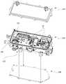
도 1은 본 발명의 일 실시 예에 따른 전자 부품 패키지의 분해 사시도이고, 도 2는 도 1의 변형예이다.1 is an exploded perspective view of an electronic component package according to an embodiment of the present invention, and FIG. 2 is a modified example of FIG. 1 .
도 1을 참고하면, 전자 부품 패키지는 제1면(111)에 복수 개의 전자 부품(11)이 배치되고 제2면(112)에는 냉각채널이 형성된 냉각패널(100)과, 냉각패널(100)의 제1면(111)을 커버하는 제1커버(210), 및 냉각패널(100)의 제2면(112)을 커버하는 제2커버(220)를 포함한다.Referring to FIG. 1 , an electronic component package includes a
전자 부품 패키지는 냉각패널(100)의 제1면(111)에 복수 개의 전자 부품(11)이 실장되는 다양한 종류의 패키지일 수 있다. 예를 들면, 전자 부품 패키지는 DC/DC 컨버터, AC/DC 컨버터 등 다양한 전자 제품일 수 있다.The electronic component package may be various types of packages in which a plurality of
냉각패널(100)은 복수 개의 전자 부품(11)에서 발생한 열을 방출하기 위하여 제2면(112)에는 냉각채널이 배치될 수 있다. 즉, 냉각패널(100)은 제1면(111)에 복수의 부품(11)이 배치되는 공간부가 배치되고, 2면에는 냉각채널이 배치될 수 있다.A cooling channel may be disposed on the
제1커버(210)는 제1면(111)과 나사 결합하여 복수 개의 전자 부품(11)을 밀폐하고, 제2커버(220)는 제2면(112)과 나사 결합하여 냉각채널(120)을 밀폐할 수 있다. 결합 방법은 나사 결합을 예시하였으나 반드시 이에 한정하지 않는다.The
도 2를 참고하면, 제1커버(210)는 제2커버(220)를 향해 돌출된 보스(211)를 포함할 수 있다. 보스(211)는 냉각패널(100)의 측면에 배치된 결합부(113)를 관통하여 제2커버(220)와 나사 결합할 수 있다. 그러나, 반드시 이에 한정하는 것은 아니고 제2커버(220)에 보스가 배치될 수도 있다.Referring to FIG. 2 , the
이러한 구조에 의하면, 제1커버(210)와 냉각패널(100)의 나사 결합을 생략할 수 있어 신속한 조립이 가능하고, 나사를 절약할 수 있어 재료비를 절감할 수 있다.According to this structure, it is possible to omit the screw coupling between the
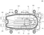
도 3은 도 1의 냉각패널의 평면도이고, 도 4는 도 1의 냉각패널의 저면도이고, 도 5는 냉각패널에 유입된 냉각수의 흐름을 설명하기 위한 도면이다.FIG. 3 is a plan view of the cooling panel of FIG. 1 , FIG. 4 is a bottom view of the cooling panel of FIG. 1 , and FIG. 5 is a view for explaining the flow of cooling water introduced into the cooling panel.
도 3을 참고하면, 냉각패널(100)의 제1면(111)에는 복수 개의 전자 부품(11)이 배치될 수 있다. 전자 부품(11)은 회로 기판(12)에 실장되어 제1면(111)에 장착될 수 있다.Referring to FIG. 3 , a plurality of
전자 부품 패키지가 DC/DC 컨버터인 경우, 전자 부품(11)은 복수 개의 MOSFET으로 구성된 스위칭부, 트랜스포머, 및 정류 다이오드 등을 포함할 수 있다. 이러한 전자 제품은 상대적으로 다른 부품에 비해 열이 과도하게 발생할 수 있다. 즉, 도면을 기준으로 상대적으로 상부측이 고온 영역(R1)일 수 있다.When the electronic component package is a DC/DC converter, the
도 4를 참고하면, 냉각패널(100)의 제2면(112)에는 냉각채널(120)이 배치될 수 있다. 냉각채널(120)은 냉각수가 유입되어 순환하는 제1채널영역(121)과, 냉각수가 순환한 후 배출되는 제2채널영역(122)을 포함할 수 있다.Referring to FIG. 4 , a
냉각수 유입구(130)는 제1채널영역(121)과 연결되고, 냉각수 토출구(140)는 제2채널영역(122)과 연결될 수 있다. 냉각수 유입구(130)와 냉각수 토출구(140)는 냉각패널(100)의 일 측에 나란히 배치될 수 있다. 즉, 냉각채널(120)은 U자 형상을 포함할 수 있다.The
제1채널영역(121)과 제2채널영역(122)은 냉각수 유입구(130)가 배치된 일 측에서 타 측으로 연장되는 분기라인(123)에 의해 구분될 수 있다. 즉, 분리라인(123)을 연장한 가상선(P1)을 기준으로 제1채널영역(121)과 제2채널영역(122)은 서로 대칭일 수 있다.The
제1채널영역(121)과 제2채널영역(122)은 복수 개의 가이드(G1)를 포함할 수 있다. 이때, 제1채널영역(121)에 배치되는 가이드(G1)의 밀도는 제2채널영역(122)에 배치되는 가이드(G2)의 밀도보다 높을 수 있다. 즉, 제1채널영역(121)에 가이드가 더 조밀하게 배치될 수 있다.The
제1채널영역(121)과 제2채널영역(122)에 복수 개의 가이드(G1, G2)가 배치된 제1영역(R2)은 도 3의 고온 영역(R1)과 매칭될 수 있다. 제1영역(R2)은 나머지 영역에 비해 상대적으로 유압이 높은 영역이므로 와류(eddy) 등이 발생하는 경우 냉각 효율이 상대적으로 감소할 수 있다. 따라서, 고온 영역의 냉각 효율을 높이기 위해 제1영역(R2)에는 복수 개의 가이드(G1, G2)가 배치된다.The first region R2 in which the plurality of guides G1 and G2 are disposed in the
도 5를 참고하면, 제1채널영역(121)은 제1가이드(131), 및 제1가이드(131)를 기준으로 서로 마주보게 배치되는 제2가이드(132) 및 제3가이드(133)를 포함할 수 있다. 제1 내지 제3가이드(131, 132 133)는 냉각수의 이동 방향을 따라 소정의 길이로 연장될 수 있다.Referring to FIG. 5 , the
제1가이드(131)는 제2, 제3 가이드(132, 133)보다 냉각수 유입구(130)에 인접 배치되므로, 유입되는 냉각수는 2개로 채널로 분기될 수 있다. 이러한 구성에 의해 와류 현상을 억제하거나, 냉각수 유속을 균일하게 유지할 수 있다. 제1가이드(131)의 일단(131a)과 냉각수 유입구(130) 사이의 거리(L1)는 약 1cm일 수 있으나, 이에 한정하지는 않는다.Since the
제1채널영역(121)은 냉각수 유입구(130)와 연결되는 제1테이퍼부(121a)를 포함할 수 있다. 제1테이퍼부(121a)는 냉각수 유입구(130)와 멀어질수록 폭이 넓어질 수 있다. 제1테이퍼부(121a)의 폭은 P1과 수직한 방향의 길이로 정의할 수 있다. 이러한 구성에 의하면 냉각수의 수압을 효과적으로 제어할 수 있다.The
제2가이드(132) 및 제3가이드(133)의 일 단과 냉각수 유입구(130) 사이의 거리(L2)는 제1테이퍼부(121a)가 최대 폭이 되는 지점(P2)과 냉각수 유입구(130) 사이의 거리(L3)보다 짧을 수 있다. 이러한 구성에 의하면 제2가이드(132) 및 제3가이드(133)가 냉각수를 다시 2개의 채널로 분기시킴으로써 수압을 조절할 수 있다. 따라서, 제1테이퍼부(121a)가 최대 폭이 되는 지점(P2)에서 와류가 발생하는 현상을 개선할 수 있다.The distance L2 between one end of the
제1가이드(131)는 제1채널영역(121)에서 제2채널영역(122)까지 연장되는 반면, 제2, 제3가이드(133)는 제1채널영역(121)에만 배치될 수 있다.The
제2채널영역(122)은 제1가이드(131) 및 제4가이드(134)를 포함할 수 있다. 이때, 제4가이드(134)의 일단(134a)은 소정의 곡률을 가질 수 있다. 제2채널영역(122)은 냉각수 토출구(140)와 연결되는 제2테이퍼부(122a)를 포함할 수 있다.The
제1채널영역(121)과 제2채널영역(122)에는 복수 개의 돌출부(141)가 배치될 수 있다. 돌출부(141)는 제1면을 가압하여 형성될 수 있다. 즉, 제1면에 전자 부품 및/또는 회로기판을 고정하기 위해 나사홈을 형성하는 경우 제2면(112)에는 이러한 돌출부(141)가 형성될 수 있다.A plurality of
제1채널영역(121)에 배치된 돌출부(141)의 개수는 제2채널영역(122)에 배치된 돌출부(141)의 개수보다 많을 수 있다. 이는 제1영역(R2)에 상대적으로 많은 전자 부품이 배치되기 때문일 수 있다.The number of
도 6은 제1가이드만 배치된 냉각패널의 열 유동 분석 결과이고, 도 7은 도 1의 냉각패널의 열 유동 분석 결과이다.6 is a heat flow analysis result of the cooling panel in which only the first guide is disposed, and FIG. 7 is a heat flow analysis result of the cooling panel of FIG. 1 .
도 6을 참고하면, 제1채널영역(121)은 제1테이퍼부(121a)의 끝단 지점(P2)에서 와류(S1, S2)가 발생하는 것을 확인할 수 있다. 또한, 제2채널영역(122)은 분기라인(123)과 인접하는 영역에서 와류(S3)가 발생하는 것을 알 수 있다.Referring to FIG. 6 , it can be seen that eddy currents S1 and S2 are generated in the
그러나, 도 7을 참고하면, 제2, 제3가이드(132, 133)가 배치됨으로써 와류 현상이 개선된 것을 확인할 수 있다. 즉, 제2, 제3가이드(132, 133)가 제1테이퍼부(121a)의 끝단(P2) 보다 냉각수 유입구(130)측으로 돌출 배치됨으로써 냉각수의 흐름이 개선되어 와류 현상이 억제될 수 있다.However, referring to FIG. 7 , it can be seen that the vortex phenomenon is improved by disposing the second and
또한, 제4가이드(134)에 의해 와류 현상이 개선된 것을 확인할 수 있다. 이때, 제4가이드(134)의 일단(134a)은 곡률이 형성될 수 있다. 이때, 제4가이드의 일단(134a)에 형성된 곡률은 대응되는 위치에서 제1가이드(131)의 곡률보다 작을 수 있다. 따라서, 효과적인 유속 제어가 가능해질 수 있다.In addition, it can be seen that the vortex phenomenon is improved by the
100: 냉각패널
111: 제1면
112: 제2면
120: 냉각채널
121: 제1채널영역
121a: 제1테이퍼부
122: 제2채널영역
123: 분기라인
131: 제1가이드
132: 제2가이드
133: 제3가이드
134: 제4가이드100: cooling panel
111: first side
112: second side
120: cooling channel
121: first channel area
121a: first tapered portion
122: second channel area
123: branch line
131: first guide
132: second guide
133: third guide
134: fourth guide
Claims (15)
Translated fromKorean상기 제2면에 배치되고 냉각수가 유입되는 제1채널영역과, 냉각수가 배출되는 제2채널영역을 포함하는 냉각채널;
일 측에 배치되어 상기 제1채널영역과 연결되는 냉각수 유입구, 및
일 측에 배치되어 상기 제2채널영역과 연결되는 냉각수 토출구를 포함하고,
상기 제1채널영역과 제2채널영역은 복수 개의 가이드를 포함하고,
상기 제1채널영역에 배치되는 가이드의 밀도는 상기 제2채널영역에 배치되는 가이드의 밀도보다 높고,
상기 제1채널영역은 제1가이드, 및 상기 제1가이드를 기준으로 서로 마주보게 배치되는 제2가이드 및 제3가이드를 포함하고,
상기 제1가이드의 일 단은 상기 제2, 제3 가이드의 일 단보다 상기 냉각수 유입구에 인접 배치되고,
상기 제1가이드는 상기 냉각수 유입구의 길이방향 중심축과 가장 가깝게 배치되는 냉각패널.
first and second surfaces facing each other;
a cooling channel disposed on the second surface and including a first channel region through which cooling water is introduced and a second channel region through which cooling water is discharged;
a cooling water inlet disposed on one side and connected to the first channel region; and
and a coolant outlet disposed on one side and connected to the second channel region;
The first channel region and the second channel region include a plurality of guides,
The density of the guides disposed in the first channel region is higher than the density of the guides disposed in the second channel region;
The first channel region includes a first guide, and a second guide and a third guide disposed to face each other with respect to the first guide,
One end of the first guide is disposed closer to the coolant inlet than one end of the second and third guides,
The first guide is a cooling panel disposed closest to the longitudinal central axis of the cooling water inlet.
상기 제1채널영역과 제2채널영역은 서로 대칭 형상인 냉각패널.
According to claim 1,
The first channel region and the second channel region are symmetrical to each other.
상기 제1채널영역은 상기 냉각수 유입구로 연결되는 제1테이퍼부를 포함하고,
상기 제1테이퍼부는 상기 냉각수 유입구와 멀어질수록 폭이 넓어지는 냉각패널.
According to claim 1,
The first channel region includes a first tapered portion connected to the coolant inlet,
A cooling panel in which the width of the first tapered portion increases as it moves away from the coolant inlet.
상기 제2가이드 및 제3가이드의 일 단과 상기 냉각수 유입구 사이의 거리는 상기 제1테이퍼부가 최대 폭이 되는 지점과 상기 냉각수 유입구 사이의 거리보다 짧은 냉각패널.
6. The method of claim 5,
A distance between one end of the second and third guides and the coolant inlet is shorter than a distance between a point at which the first tapered portion has a maximum width and the coolant inlet.
상기 제1가이드는 상기 제2채널영역까지 연장 형성되는 냉각패널.
According to claim 1,
The first guide is formed to extend to the second channel region.
상기 제1채널영역과 제2채널영역에는 복수 개의 돌출부를 포함하고,
상기 제1채널영역에 배치된 돌출부의 개수는 상기 제2채널영역에 배치된 돌출부의 개수보다 많은 냉각패널.
According to claim 1,
The first channel region and the second channel region include a plurality of protrusions,
The number of protrusions disposed in the first channel region is greater than the number of protrusions disposed in the second channel region.
상기 냉각채널은 U자 형상을 포함하는 냉각패널.
According to claim 1,
The cooling channel is a cooling panel comprising a U-shape.
상기 냉각패널과 결합하여 상기 제1면을 커버하는 제1커버; 및
상기 냉각패널과 결합하여 상기 제2면을 커버하는 제2커버를 포함하고,
상기 냉각 채널은 냉각수가 유입되는 제1채널영역과, 냉각수가 배출되는 제2채널영역을 포함하고,
상기 제1채널영역과 제2채널영역은 복수 개의 가이드를 포함하고,
상기 냉각패널은 일 측에 배치되어 상기 제1채널영역과 연결되는 냉각수 유입구, 및 일 측에 배치되어 상기 제2채널영역과 연결되는 냉각수 토출구를 포함하고,
상기 제1채널영역에 배치되는 가이드의 밀도는 상기 제2채널영역에 배치되는 가이드의 밀도보다 높고,
상기 제1채널영역은 제1가이드, 및 상기 제1가이드를 기준으로 서로 마주보게 배치되는 제2가이드 및 제3가이드를 포함하고,
상기 제1가이드의 일 단은 상기 제2, 제3 가이드의 일 단 보다 상기 냉각수 유입구에 인접 배치되고,
상기 제1가이드는 상기 냉각수 유입구의 길이방향 중심축과 가장 가깝게 배치되는 전자 부품 패키지.
a cooling panel having a plurality of electronic components and a circuit board disposed on a first surface and a cooling channel formed on a second surface;
a first cover coupled to the cooling panel to cover the first surface; and
and a second cover coupled to the cooling panel to cover the second surface,
The cooling channel includes a first channel region through which coolant is introduced and a second channel region through which coolant is discharged,
The first channel region and the second channel region include a plurality of guides,
The cooling panel includes a coolant inlet disposed on one side and connected to the first channel region, and a coolant outlet disposed on one side and connected to the second channel region,
The density of the guides arranged in the first channel region is higher than the density of the guides arranged in the second channel region,
The first channel region includes a first guide, and a second guide and a third guide disposed to face each other with respect to the first guide,
One end of the first guide is disposed closer to the coolant inlet than one end of the second and third guides,
and the first guide is disposed closest to a longitudinal central axis of the cooling water inlet.
상기 제1채널영역은 상기 냉각수 유입구로 연결되는 제1테이퍼부를 포함하고,
상기 제1테이퍼부는 상기 냉각수 유입구와 멀어질수록 폭이 넓어지는 전자 부품 패키지.
11. The method of claim 10,
The first channel region includes a first tapered portion connected to the coolant inlet,
The width of the first tapered portion increases as the distance from the coolant inlet is increased.
상기 제2가이드 및 제3가이드의 일 단과 상기 냉각수 유입구 사이의 거리는 상기 제1테이퍼부가 최대 폭이 되는 지점과 상기 냉각수 유입구 사이의 거리보다 짧은 전자 부품 패키지.
14. The method of claim 13,
A distance between one end of the second and third guides and the coolant inlet is shorter than a distance between a point at which the first tapered portion has a maximum width and the coolant inlet.
상기 제1가이드는 상기 제2채널영역까지 연장 형성되는 전자 부품 패키지.11. The method of claim 10,
The first guide is an electronic component package extending to the second channel region.
Priority Applications (8)
| Application Number | Priority Date | Filing Date | Title |
|---|---|---|---|
| KR1020150156820AKR102458066B1 (en) | 2015-11-09 | 2015-11-09 | Cooling pannel and electronic component package including the same |
| US15/344,907US9907217B2 (en) | 2015-11-09 | 2016-11-07 | Cooling panel and electronic component package including the same |
| CN202111150960.2ACN114007376A (en) | 2015-11-09 | 2016-11-08 | Cooling plate and electronic component package including the same |
| CN201610982799.8ACN106910727B (en) | 2015-11-09 | 2016-11-08 | Cooling plate and electronic component package including the same |
| CN202111153815.XACN114007378A (en) | 2015-11-09 | 2016-11-08 | Cooling plate and electronic component package including the same |
| KR1020220134726AKR102595645B1 (en) | 2015-11-09 | 2022-10-19 | Cooling pannel and electronic component package including the same |
| KR1020230143682AKR102788995B1 (en) | 2015-11-09 | 2023-10-25 | Cooling pannel and electronic component package including the same |
| KR1020250038708AKR20250048667A (en) | 2015-11-09 | 2025-03-26 | Cooling pannel and electronic component package including the same |
Applications Claiming Priority (1)
| Application Number | Priority Date | Filing Date | Title |
|---|---|---|---|
| KR1020150156820AKR102458066B1 (en) | 2015-11-09 | 2015-11-09 | Cooling pannel and electronic component package including the same |
Related Child Applications (1)
| Application Number | Title | Priority Date | Filing Date |
|---|---|---|---|
| KR1020220134726ADivisionKR102595645B1 (en) | 2015-11-09 | 2022-10-19 | Cooling pannel and electronic component package including the same |
Publications (2)
| Publication Number | Publication Date |
|---|---|
| KR20170054092A KR20170054092A (en) | 2017-05-17 |
| KR102458066B1true KR102458066B1 (en) | 2022-10-24 |
Family
ID=58664204
Family Applications (4)
| Application Number | Title | Priority Date | Filing Date |
|---|---|---|---|
| KR1020150156820AActiveKR102458066B1 (en) | 2015-11-09 | 2015-11-09 | Cooling pannel and electronic component package including the same |
| KR1020220134726AActiveKR102595645B1 (en) | 2015-11-09 | 2022-10-19 | Cooling pannel and electronic component package including the same |
| KR1020230143682AActiveKR102788995B1 (en) | 2015-11-09 | 2023-10-25 | Cooling pannel and electronic component package including the same |
| KR1020250038708APendingKR20250048667A (en) | 2015-11-09 | 2025-03-26 | Cooling pannel and electronic component package including the same |
Family Applications After (3)
| Application Number | Title | Priority Date | Filing Date |
|---|---|---|---|
| KR1020220134726AActiveKR102595645B1 (en) | 2015-11-09 | 2022-10-19 | Cooling pannel and electronic component package including the same |
| KR1020230143682AActiveKR102788995B1 (en) | 2015-11-09 | 2023-10-25 | Cooling pannel and electronic component package including the same |
| KR1020250038708APendingKR20250048667A (en) | 2015-11-09 | 2025-03-26 | Cooling pannel and electronic component package including the same |
Country Status (3)
| Country | Link |
|---|---|
| US (1) | US9907217B2 (en) |
| KR (4) | KR102458066B1 (en) |
| CN (3) | CN114007378A (en) |
Families Citing this family (8)
| Publication number | Priority date | Publication date | Assignee | Title |
|---|---|---|---|---|
| KR102458066B1 (en)* | 2015-11-09 | 2022-10-24 | 엘지이노텍 주식회사 | Cooling pannel and electronic component package including the same |
| KR102675482B1 (en)* | 2016-08-05 | 2024-06-17 | 엘지이노텍 주식회사 | Electronic component package |
| KR102458279B1 (en)* | 2017-11-09 | 2022-10-25 | 엘지이노텍 주식회사 | Dc-dc converter |
| US11251694B2 (en) | 2016-11-17 | 2022-02-15 | Lg Innotek Co., Ltd. | DC-DC converter |
| KR102095915B1 (en)* | 2017-12-29 | 2020-04-01 | 주식회사 유라코퍼레이션 | Cooling structure of charging device for electric vehicle |
| IT201800003204A1 (en)* | 2018-03-02 | 2019-09-02 | Eldor Corp Spa | SUPPORT ORGAN FOR POWER ELECTRONICS DEVICES AND METHOD OF REALIZATION OF THE SAME |
| CN110430728A (en)* | 2019-07-31 | 2019-11-08 | 联想(北京)有限公司 | Cooling device and electronic equipment |
| KR102334216B1 (en)* | 2020-04-29 | 2021-12-02 | 주식회사 디에이치지 | Cooling water channel structure of heat management apparatus for improve the cooling water folw of the battery for electric vehicle |
Citations (3)
| Publication number | Priority date | Publication date | Assignee | Title |
|---|---|---|---|---|
| US20090206662A1 (en)* | 2008-02-15 | 2009-08-20 | Aisin Aw Co., Ltd. | Inverter unit |
| JP2013138541A (en) | 2011-12-28 | 2013-07-11 | Tdk Corp | Power source unit and cooling device of power source device |
| JP2014060248A (en)* | 2012-09-18 | 2014-04-03 | Toyota Motor Corp | Cooler |
Family Cites Families (25)
| Publication number | Priority date | Publication date | Assignee | Title |
|---|---|---|---|---|
| KR920015975A (en)* | 1991-01-23 | 1992-08-27 | 이용구 | Forced cooling method and device for electronic parts |
| US5912800A (en)* | 1997-09-03 | 1999-06-15 | International Business Machines Corporation | Electronic packages and method to enhance the passive thermal management of electronic packages |
| JP2002046482A (en)* | 2000-07-31 | 2002-02-12 | Honda Motor Co Ltd | Heat sink type cooling device |
| JP4561632B2 (en)* | 2003-06-27 | 2010-10-13 | 日本電気株式会社 | Electronic equipment cooling device |
| FR2861894B1 (en)* | 2003-10-31 | 2008-01-18 | Valeo Equip Electr Moteur | DEVICE FOR COOLING A POWER ELECTRONIC |
| JP4848187B2 (en)* | 2006-01-17 | 2011-12-28 | 日立オートモティブシステムズ株式会社 | Power converter |
| JP4770490B2 (en)* | 2006-01-31 | 2011-09-14 | トヨタ自動車株式会社 | Power semiconductor element cooling structure and inverter |
| JP4452953B2 (en)* | 2007-08-09 | 2010-04-21 | 日立オートモティブシステムズ株式会社 | Power converter |
| JP5009249B2 (en)* | 2008-07-23 | 2012-08-22 | 新電元工業株式会社 | Cooler |
| JP4657329B2 (en)* | 2008-07-29 | 2011-03-23 | 日立オートモティブシステムズ株式会社 | Power converter and electric vehicle |
| JP4988665B2 (en)* | 2008-08-06 | 2012-08-01 | 日立オートモティブシステムズ株式会社 | Semiconductor device and power conversion device using the semiconductor device |
| KR101289313B1 (en)* | 2009-05-22 | 2013-07-24 | 엘에스산전 주식회사 | Water-cooling type cooler and inverter having the same |
| WO2012095950A1 (en)* | 2011-01-12 | 2012-07-19 | トヨタ自動車株式会社 | Cooler |
| CN102280671B (en)* | 2011-06-23 | 2013-11-27 | 台达电子企业管理(上海)有限公司 | cooling system |
| US8835039B2 (en)* | 2011-10-21 | 2014-09-16 | Avl Powertrain Engineering, Inc. | Battery cooling plate and cooling system |
| KR101328322B1 (en)* | 2011-12-08 | 2013-11-11 | 재단법인 포항산업과학연구원 | Cooling Device for Heating Parts and Power Semiconductor module having The Same |
| DE102012005870A1 (en)* | 2012-03-23 | 2013-09-26 | Valeo Klimasysteme Gmbh | Cooling device for a vehicle battery and vehicle battery with cooling device |
| KR101343141B1 (en)* | 2012-05-22 | 2013-12-19 | 엘에스산전 주식회사 | A cooling device of electric transformer |
| KR20130131603A (en)* | 2012-05-24 | 2013-12-04 | 현대모비스 주식회사 | Power modules sharing coolant passage for in-wheel system |
| KR20140006392A (en)* | 2012-07-05 | 2014-01-16 | 엘에스산전 주식회사 | Electronic component box for vehicle |
| JP5738817B2 (en)* | 2012-09-14 | 2015-06-24 | 日立オートモティブシステムズ株式会社 | Power converter |
| DE102014202293A1 (en)* | 2014-02-07 | 2015-08-13 | Siemens Aktiengesellschaft | heatsink |
| WO2016021565A1 (en)* | 2014-08-06 | 2016-02-11 | 富士電機株式会社 | Semiconductor device |
| JP6447149B2 (en)* | 2015-01-13 | 2019-01-09 | 富士通株式会社 | Heat exchanger, cooling unit, and electronic equipment |
| KR102458066B1 (en)* | 2015-11-09 | 2022-10-24 | 엘지이노텍 주식회사 | Cooling pannel and electronic component package including the same |
- 2015
- 2015-11-09KRKR1020150156820Apatent/KR102458066B1/enactiveActive
- 2016
- 2016-11-07USUS15/344,907patent/US9907217B2/enactiveActive
- 2016-11-08CNCN202111153815.XApatent/CN114007378A/enactivePending
- 2016-11-08CNCN201610982799.8Apatent/CN106910727B/enactiveActive
- 2016-11-08CNCN202111150960.2Apatent/CN114007376A/enactivePending
- 2022
- 2022-10-19KRKR1020220134726Apatent/KR102595645B1/enactiveActive
- 2023
- 2023-10-25KRKR1020230143682Apatent/KR102788995B1/enactiveActive
- 2025
- 2025-03-26KRKR1020250038708Apatent/KR20250048667A/enactivePending
Patent Citations (3)
| Publication number | Priority date | Publication date | Assignee | Title |
|---|---|---|---|---|
| US20090206662A1 (en)* | 2008-02-15 | 2009-08-20 | Aisin Aw Co., Ltd. | Inverter unit |
| JP2013138541A (en) | 2011-12-28 | 2013-07-11 | Tdk Corp | Power source unit and cooling device of power source device |
| JP2014060248A (en)* | 2012-09-18 | 2014-04-03 | Toyota Motor Corp | Cooler |
Also Published As
| Publication number | Publication date |
|---|---|
| KR20220147558A (en) | 2022-11-03 |
| CN114007376A (en) | 2022-02-01 |
| KR102788995B1 (en) | 2025-03-31 |
| CN106910727A (en) | 2017-06-30 |
| CN106910727B (en) | 2021-10-26 |
| US9907217B2 (en) | 2018-02-27 |
| KR20230152635A (en) | 2023-11-03 |
| KR20170054092A (en) | 2017-05-17 |
| KR102595645B1 (en) | 2023-10-30 |
| KR20250048667A (en) | 2025-04-10 |
| CN114007378A (en) | 2022-02-01 |
| US20170135252A1 (en) | 2017-05-11 |
Similar Documents
| Publication | Publication Date | Title |
|---|---|---|
| KR102458066B1 (en) | Cooling pannel and electronic component package including the same | |
| KR102457660B1 (en) | Power conversion device | |
| JP6365691B2 (en) | Semiconductor device | |
| JP5532001B2 (en) | Power converter | |
| US11984383B2 (en) | Semiconductor device | |
| US20210329815A1 (en) | Electric power module and inverter apparatus having the same | |
| EP3496521B1 (en) | Electronic component package | |
| KR102458279B1 (en) | Dc-dc converter | |
| KR102445246B1 (en) | Power conversion device | |
| KR102515289B1 (en) | A cap for electronic device | |
| KR102722571B1 (en) | Electronic component package | |
| KR20140003080A (en) | Cooling system for electric power apparatus | |
| KR102454400B1 (en) | Heat Emission Structure and Cooling Device using the same | |
| KR102654809B1 (en) | Power converter | |
| JP7316193B2 (en) | power converter | |
| KR20130134166A (en) | Cooling system for electric power apparatus | |
| KR101865963B1 (en) | Apparatus for cooling switching element for converter |
Legal Events
| Date | Code | Title | Description |
|---|---|---|---|
| PA0109 | Patent application | St.27 status event code:A-0-1-A10-A12-nap-PA0109 | |
| R18-X000 | Changes to party contact information recorded | St.27 status event code:A-3-3-R10-R18-oth-X000 | |
| PG1501 | Laying open of application | St.27 status event code:A-1-1-Q10-Q12-nap-PG1501 | |
| P22-X000 | Classification modified | St.27 status event code:A-2-2-P10-P22-nap-X000 | |
| R18-X000 | Changes to party contact information recorded | St.27 status event code:A-3-3-R10-R18-oth-X000 | |
| R18-X000 | Changes to party contact information recorded | St.27 status event code:A-3-3-R10-R18-oth-X000 | |
| A201 | Request for examination | ||
| PA0201 | Request for examination | St.27 status event code:A-1-2-D10-D11-exm-PA0201 | |
| D13-X000 | Search requested | St.27 status event code:A-1-2-D10-D13-srh-X000 | |
| D14-X000 | Search report completed | St.27 status event code:A-1-2-D10-D14-srh-X000 | |
| PN2301 | Change of applicant | St.27 status event code:A-3-3-R10-R13-asn-PN2301 St.27 status event code:A-3-3-R10-R11-asn-PN2301 | |
| E902 | Notification of reason for refusal | ||
| PE0902 | Notice of grounds for rejection | St.27 status event code:A-1-2-D10-D21-exm-PE0902 | |
| T11-X000 | Administrative time limit extension requested | St.27 status event code:U-3-3-T10-T11-oth-X000 | |
| E13-X000 | Pre-grant limitation requested | St.27 status event code:A-2-3-E10-E13-lim-X000 | |
| P11-X000 | Amendment of application requested | St.27 status event code:A-2-2-P10-P11-nap-X000 | |
| P13-X000 | Application amended | St.27 status event code:A-2-2-P10-P13-nap-X000 | |
| E701 | Decision to grant or registration of patent right | ||
| PE0701 | Decision of registration | St.27 status event code:A-1-2-D10-D22-exm-PE0701 | |
| A107 | Divisional application of patent | ||
| GRNT | Written decision to grant | ||
| PA0107 | Divisional application | St.27 status event code:A-0-1-A10-A18-div-PA0107 St.27 status event code:A-0-1-A10-A16-div-PA0107 | |
| PR0701 | Registration of establishment | St.27 status event code:A-2-4-F10-F11-exm-PR0701 | |
| PR1002 | Payment of registration fee | St.27 status event code:A-2-2-U10-U11-oth-PR1002 Fee payment year number:1 | |
| PG1601 | Publication of registration | St.27 status event code:A-4-4-Q10-Q13-nap-PG1601 | |
| P22-X000 | Classification modified | St.27 status event code:A-4-4-P10-P22-nap-X000 | |
| PR1001 | Payment of annual fee | St.27 status event code:A-4-4-U10-U11-oth-PR1001 Fee payment year number:4 |