KR102457236B1 - Beverage maker - Google Patents
Beverage makerDownload PDFInfo
- Publication number
- KR102457236B1 KR102457236B1KR1020170146918AKR20170146918AKR102457236B1KR 102457236 B1KR102457236 B1KR 102457236B1KR 1020170146918 AKR1020170146918 AKR 1020170146918AKR 20170146918 AKR20170146918 AKR 20170146918AKR 102457236 B1KR102457236 B1KR 102457236B1
- Authority
- KR
- South Korea
- Prior art keywords
- beverage
- capsule
- siphon
- channel
- gas
- Prior art date
- Legal status (The legal status is an assumption and is not a legal conclusion. Google has not performed a legal analysis and makes no representation as to the accuracy of the status listed.)
- Active
Links
Images


Classifications
- B—PERFORMING OPERATIONS; TRANSPORTING
- B65—CONVEYING; PACKING; STORING; HANDLING THIN OR FILAMENTARY MATERIAL
- B65D—CONTAINERS FOR STORAGE OR TRANSPORT OF ARTICLES OR MATERIALS, e.g. BAGS, BARRELS, BOTTLES, BOXES, CANS, CARTONS, CRATES, DRUMS, JARS, TANKS, HOPPERS, FORWARDING CONTAINERS; ACCESSORIES, CLOSURES, OR FITTINGS THEREFOR; PACKAGING ELEMENTS; PACKAGES
- B65D85/00—Containers, packaging elements or packages, specially adapted for particular articles or materials
- B65D85/70—Containers, packaging elements or packages, specially adapted for particular articles or materials for materials not otherwise provided for
- B65D85/804—Disposable containers or packages with contents which are mixed, infused or dissolved in situ, i.e. without having been previously removed from the package
- C—CHEMISTRY; METALLURGY
- C12—BIOCHEMISTRY; BEER; SPIRITS; WINE; VINEGAR; MICROBIOLOGY; ENZYMOLOGY; MUTATION OR GENETIC ENGINEERING
- C12C—BEER; PREPARATION OF BEER BY FERMENTATION; PREPARATION OF MALT FOR MAKING BEER; PREPARATION OF HOPS FOR MAKING BEER
- C12C13/00—Brewing devices, not covered by a single group of C12C1/00 - C12C12/04
- C12C13/10—Home brew equipment
Landscapes
- Engineering & Computer Science (AREA)
- Chemical & Material Sciences (AREA)
- Organic Chemistry (AREA)
- Bioinformatics & Cheminformatics (AREA)
- Life Sciences & Earth Sciences (AREA)
- Biochemistry (AREA)
- Health & Medical Sciences (AREA)
- General Engineering & Computer Science (AREA)
- General Health & Medical Sciences (AREA)
- Genetics & Genomics (AREA)
- Food Science & Technology (AREA)
- Wood Science & Technology (AREA)
- Zoology (AREA)
- Mechanical Engineering (AREA)
- Apparatus For Making Beverages (AREA)
Abstract
Translated fromKoreanDescription
Translated fromKorean본 발명은 사이폰 캡이 마련된 음료 캡슐 및 이를 포함하는 음료 제조기에 관한 것이다.The present invention relates to a beverage capsule provided with a siphon cap and a beverage maker including the same.
음료는 술이나 차 등의 음용 가능한 액체를 총칭한다. 예컨대, 음료는 갈증을 해결하기 위한 물(음료수), 독특한 향과 맛을 갖는 과즙음료, 청량감을 주는 청량음료, 각성효과를 기대할 수 있는 기호음료, 또는 알코올 효과가 있는 알코올 음료 등 다양한 카테고리로 구분될 수 있다.Beverage is a generic term for drinkable liquids such as alcohol or tea. For example, beverages are divided into various categories such as water (drinks) to quench thirst, juice drinks with a unique flavor and taste, soft drinks that give a refreshing feeling, preference drinks that can be expected to have arousal effect, or alcoholic drinks with alcohol effects can be
이러한 음료의 대표적인 예로서 음료가 있다. 음료는 보리를 싹틔워 만든 맥아(麥芽. 엿기름)로 즙을 만들어 여과한 후, 홉(hop)을 첨가하고 효모로 발효시켜 만든 술이다.A representative example of such a beverage is a beverage. Beverage is an alcoholic beverage made from malt made by sprouting barley, filtered, and fermented with yeast after adding hops.
소비자는 음료제조회사에서 제조하여 판매하는 기성품을 구입하거나 가정 또는 술집에서 음료의 재료를 직접 발효시킨 하우스음료(또는 수제음료)를 음용할 수 있다.Consumers can purchase ready-made products manufactured and sold by beverage manufacturers, or drink house beverages (or homemade beverages) made by fermenting beverage ingredients at home or at a bar.
하우스음료는 기성품보다 다양한 종류로 제조될 수 있고, 소비자 취향에 맞게 제조될 수 있다.House drinks can be manufactured in a variety of types rather than ready-made products, and can be manufactured according to consumer preferences.
음료 제조를 위한 재료는 물과, 맥아, 홉(hop), 이스트, 향 재료 등 일 수 있다.Materials for preparing the beverage may be water, malt, hops, yeast, flavoring materials, and the like.
이스트는 효모라 불릴 수 있고, 맥아에 첨가되어 맥아를 발효시킬 수 있고 알코올과 탄산을 생성하는 것을 도울 수 있다.Yeast can be called yeast and can be added to the malt to ferment the malt and help produce alcohol and carbonic acid.
통상적으로 하우스 음료는 맥즙생성단계, 발효단계, 숙성단계의 총 3단계를 포함할 수 있고, 맥즙생성단계에서 숙성단계까지 2주에서 3주 정도 소요될 수 있다.Typically, a house beverage may include a total of three stages of a wort production step, a fermentation step, and a maturation step, and it may take 2 to 3 weeks from the wort production step to the aging step.
하우스 음료는 발효 단계시 최적의 온도를 유지하는 것이 중요하고, 간편하게 제조될수록 사용자의 편의성을 증대시킬 수 있다.For house drinks, it is important to maintain the optimum temperature during the fermentation stage, and the more conveniently manufactured, the more convenient the user can be.
최근에는 가정이나 술집에서 손쉽게 하우스 음료를 제조할 수 있는 음료 제조기가 점차 사용되는 추세이고, 이러한 음료 제조기는 최대한 자동화 가능하게 구성되는 것이 바람직하다.Recently, a beverage maker that can easily produce house drinks at home or a bar is gradually being used, and it is preferable that such a beverage maker is configured to be as automated as possible.
본 발명은 음료 캡슐 내부에 수용된 음료 재료를 효과적으로 추출할 수 있는 음료 제조기를 제공하는데 그 목적이 있다.An object of the present invention is to provide a beverage maker capable of effectively extracting the beverage material accommodated in the beverage capsule.
본 발명의 과제를 해결하기 위한 일 측면에 따르면, 음료 캡슐은 재료수용공간이 형성되고 내부에 사이폰 튜브가 돌출된 캡슐 바디와, 상기 재료수용공간에 수용되고 상기 사이폰 튜브를 둘러싸도록 배치된 사이폰 캡과, 상기 사이폰 캡 보다 크게 형성되고, 상기 캡슐 바디와 결합되어 상기 재료수용공간을 차폐하는 실링 바디를 포함할 수 있다.According to one aspect for solving the problems of the present invention, the beverage capsule is a capsule body in which a material receiving space is formed and a siphon tube protrudes therein, and is accommodated in the material receiving space and arranged to surround the siphon tube. It may include a siphon cap and a sealing body that is formed larger than the siphon cap and is coupled to the capsule body to shield the material accommodating space.
상기 사이폰 튜브의 상단과 상기 실링바디의 저면 사이의 거리는 상기 사이폰 캡의 높이 보다 짧게 형성될 수 있다.The distance between the upper end of the siphon tube and the bottom surface of the sealing body may be formed to be shorter than the height of the siphon cap.
상기 캡슐 바디의 하판에 분리 가능하게 결합되어 상기 사이폰 튜브의 하단을 막는 사이폰 마개를 더 포함할 수 있다. 상기 사이폰 마개는 상기 사이폰 튜브보다 큰 판체와, 상기 판체에서 돌출되고 상기 사이폰 튜브로 내삽되어 끼움되는 돌기를 포함할 수 있다.It is detachably coupled to the lower plate of the capsule body may further include a siphon stopper blocking the lower end of the siphon tube. The siphon stopper may include a larger plate than the siphon tube, and a protrusion that protrudes from the plate and is inserted and inserted into the siphon tube.
또한, 상기 사이폰 캡의 상면은 상기 실링 바디의 저면을 향하도록 형성될 수 있으며, 상기 실링 바디는 상기 사이폰 캡의 상면을 차폐하는 제1 차폐부와, 상기 캡슐 바디에 결합되는 둘레부와, 상기 제1 차폐부와 상기 둘레부 사이에 형성되어 상기 사이폰 캡과 캡슐 바디의 사이의 틈을 차폐하는 제2차폐부를 포함할 수 있다.In addition, the upper surface of the siphon cap may be formed to face the lower surface of the sealing body, and the sealing body includes a first shielding portion for shielding the upper surface of the siphon cap, a peripheral portion coupled to the capsule body, , It is formed between the first shielding portion and the peripheral portion may include a second shielding portion for shielding the gap between the siphon cap and the capsule body.
그리고, 상기 실링 바디의 하면과 상기 사이폰 캡의 상면 각각은 원형이고, 상기 실링 바디의 직경은 상기 사이폰 캡의 직경보다 크게 형성될 수 있다.In addition, each of the lower surface of the sealing body and the upper surface of the siphon cap may have a circular shape, and a diameter of the sealing body may be greater than a diameter of the siphon cap.
본 발명의 실시예에 따른 음료 제조기는 음료 재료가 수용된 음료 캡슐과; 상기 음료 캡슐이 수용되는 음료 캡슐 수용공간이 형성된 재료 공급기를 포함하고, 상기 음료 캡슐은 재료수용공간이 형성되고 내부에 사이폰 튜브가 돌출된 캡슐 바디와, 상기 재료수용공간에 수용되고 상기 사이폰 튜브를 둘러싸도록 배치된 사이폰 캡과, 상기 사이폰 캡 보다 크게 형성되고, 상기 캡슐 바디와 결합되어 상기 재료수용공간을 차폐하는 실링 바디를 포함할 수 있다.A beverage maker according to an embodiment of the present invention includes a beverage capsule containing beverage ingredients; and a material feeder having a beverage capsule accommodating space in which the beverage capsule is accommodated, wherein the beverage capsule includes a capsule body having a material accommodating space and protruding siphon tube therein, and is accommodated in the material accommodating space and the siphon It may include a siphon cap disposed to surround the tube, and a sealing body that is formed larger than the siphon cap and is coupled to the capsule body to shield the material accommodating space.
그리고, 상기 사이폰 튜브의 상단과 상기 실링바디의 저면 사이의 거리(L1)는 상기 사이폰 캡의 높이 보다 짧게 형성될 수 있다.And, the distance (L1) between the upper end of the siphon tube and the bottom surface of the sealing body may be formed to be shorter than the height of the siphon cap.
또한, 실시예에 따른 음료 제조기는 상기 캡슐 바디의 하판에 분리 가능하게 결합되어 상기 사이폰 튜브의 하단을 막는 사이폰 마개를 더 포함할 수 있다.In addition, the beverage maker according to the embodiment is detachably coupled to the lower plate of the capsule body may further include a siphon stopper blocking the lower end of the siphon tube.
본 발명의 실시 예에 따르면, 음료 재료가 사이폰 캡과 사이폰 튜브를 통해 캡슐 바디 외부로 추출될 수 있고, 캡슐 바디 또는 실링 바디에 음료 재료의 취출을 위한 별도의 홀을 천공하는 경우 보다 신뢰성이 높게 음료 재료를 추출할 수 있는 이점이 있다.According to an embodiment of the present invention, the beverage material can be extracted to the outside of the capsule body through the siphon cap and the siphon tube, and more reliable when drilling a separate hole for taking out the beverage material in the capsule body or the sealing body This has the advantage of being able to extract highly beverage ingredients.
또한, 캡슐 바디에 담겨져 있던 음료 재료가 사이폰 캡 및 사이폰 튜브를 통해 최대한 추출될 수 있고, 음료 재료가 캡슐 바디에 남는 것을 최소화한 이점이 있다.In addition, the beverage material contained in the capsule body can be extracted as much as possible through the siphon cap and the siphon tube, and there is an advantage in that the beverage material remains in the capsule body.
또한, 실링 바디가 사이폰 캡을 보호할 수 있고, 사이폰 캡이 외부로 임의 탈거되는 것을 막을 수 있는 이점이 있다.In addition, there is an advantage in that the sealing body can protect the siphon cap and prevent the siphon cap from being arbitrarily removed to the outside.
또한, 사이폰 튜브의 상단과 실링바디의 저면 사이의 거리는 사이폰 캡의 높이 보다 짧게 형성되어, 음료 캡슐이 보관중인 상태일 때 흔들리거나 뒤집혀도 사이폰 캡이 사이폰 튜브로부터 이탈하지 않고, 음료 제조시 사이폰 효과를 안정적으로 얻을 수 있다.In addition, the distance between the top of the siphon tube and the bottom of the sealing body is formed shorter than the height of the siphon cap, so that the siphon cap does not separate from the siphon tube even if it is shaken or overturned when the beverage capsule is in storage. The siphon effect can be stably obtained during manufacturing.
또한, 사이폰 튜브의 하단을 막는 사이폰 마개가 형성됨으로써, 음료 캡슐 내부의 음료 재료가 새어나가는 것을 방지할 수 있고, 음료 재료의 손실을 최소화할 수 있는 이점이 있다.In addition, by forming a siphon stopper blocking the lower end of the siphon tube, it is possible to prevent the beverage material from leaking inside the beverage capsule, there is an advantage that can minimize the loss of the beverage material.
도 1은 본 발명의 실시예에 따른 음료 제조기의 사시도,
도 2는 본 발명의 실시예에 따른 음료 제조기의 구성이 도시된 도,
도 3은 본 발명의 일실시예에 따른 음료 캡슐의 구성이 도시된 단면도,
도 4는 도 3에 개시된 음료 캡슐이 반전되었을 때의 단면도,
도 5는 도 3에 개시된 음료 캡슐에서 사이폰 마개가 분리된 단면도,
도 6은 도 3에 개시된 음료 캡슐이 음료 제조기에 투입된 상태를 나타낸 단면도,
도 7은 도 6에 개시된 음료 캡슐의 상면이 천공된 상태를 나타낸 단면도,
도 8은 도 7에 개시된 음료 캡슐 내부로 물이 유입된 상태를 나타낸 단면도,
도 9는 도 8에 개시된 음료 캡슐 내부에서 물과 액체 재료가 빠져나간 상태를 나타낸 단면도이다.1 is a perspective view of a beverage maker according to an embodiment of the present invention;
2 is a diagram showing the configuration of a beverage maker according to an embodiment of the present invention;
3 is a cross-sectional view showing the configuration of a beverage capsule according to an embodiment of the present invention;
4 is a cross-sectional view when the beverage capsule disclosed in FIG. 3 is inverted;
5 is a cross-sectional view in which the siphon stopper is separated from the beverage capsule disclosed in FIG. 3;
6 is a cross-sectional view showing a state in which the beverage capsule disclosed in FIG. 3 is put into the beverage maker;
7 is a cross-sectional view showing a state in which the upper surface of the beverage capsule disclosed in FIG. 6 is perforated;
8 is a cross-sectional view showing a state in which water is introduced into the beverage capsule disclosed in FIG. 7;
9 is a cross-sectional view showing a state in which water and liquid material have escaped from the inside of the beverage capsule disclosed in FIG. 8 .
이하에서는 본 발명의 구체적인 실시 예를 도면과 함께 상세히 설명하도록 한다.Hereinafter, specific embodiments of the present invention will be described in detail with drawings.
이하 본 명세서에서는 음료 제조기를 이용하여 제조되는 음료로서 맥주를 예로 들어 설명하고 있으나, 음료 제조기를 이용하여 제조 가능한 음료의 종류가 맥주에 한정되는 것은 아니고, 다양한 종류의 음료가 본 발명의 실시 예에 따른 음료 제조기에 의해 제조될 수 있다.Hereinafter, although beer is exemplified as a beverage manufactured using a beverage maker in the present specification, the type of beverage that can be manufactured using the beverage maker is not limited to beer, and various types of beverages are used in the embodiment of the present invention. It can be prepared by a beverage maker according to the
도 1은 본 발명의 실시예에 따른 음료 제조기의 구성이 도시된 도이다.1 is a diagram showing the configuration of a beverage maker according to an embodiment of the present invention.
도 1을 참조하면, 음료 제조기는 음료가 발효되는 공간(S1)이 형성된 발효조 어셈블리(1)를 포함한다.Referring to FIG. 1 , the beverage maker includes a
발효조 어셈블리(1)의 내부에는 음료가 제조되는 음료 제조팩(12)이 수용될 수 있고, 발효조 어셈블리(1)에는 음료 제조팩(12)이 수용되는 공간(S1)이 형성될 수 있다.A
음료 제조기는 발효조 어셈블리(1)에 연결된 메인 채널(2)를 더 포함할 수 있다. 메인 채널(2)는 발효조 어셈블리(1)의 공간(S1)으로 음료 제조에 필요한 물이나 각종 재료를 공급할 수 있다.The beverage maker may further comprise a
음료 제조기는 메인 채널(2)에 연결되고 음료 캡슐(C1)(C2)(C3)이 수용되는 재료 공급기(3)를 더 포함할 수 있다.The beverage maker may further comprise a
음료 제조기는 메인 채널(2)로 물을 급수하는 급수모듈(5)을 더 포함할 수 있다.The beverage maker may further include a
음료 제조기는 음료를 외부로 취출하는 음료 취출기(6)를 더 포함할 수 있다. 음료 취출기(6)는 메인 채널(2)에 연결된 음료 취출채널(61)를 더 포함할 수 있다. 발효조 어셈블리(1) 내부의 음료는 메인 채널(2)로 유동될 수 있고, 메인 채널(2)의 일부를 통과해 음료 취출채널(61)로 유동될 수 있다.The beverage maker may further include a
음료 제조기는 메인 채널(2)로 가스를 주입하는 가스주입기(8)를 더 포함할 수 있다.The beverage maker may further include a
발효조 어셈블리(1)에는 메인 채널(2)와 연결되는 메인 채널 연결부(115)가 형성될 수 있다. 그리고, 발효조 어셈블리(1)에는 후술하는 가스 취출채널(71)와 연결되는 가스 취출채널 연결부(121)가 형성될 수 있다.A main
발효조 어셈블리(1)는 개구부(111)가 형성된 발효조(112)와, 개구부(111)을 개폐하는 발효조 덮개(114)를 포함할 수 있다.The
발효조(112)는 내부에 음료 제조 팩(12)이 수용되는 공간(S1)이 형성될 수 있다. 발효조(112)는 복수개 부재의 결합체로 구성될 수 있다. 발효조(112)에는 발효조 어셈블리(1)의 온도를 측정하는 온도센서(16)가 설치될 수 있다. 온도센서(16)는 발효조(112)의 온도를 측정하여, 제어부(미도시)로 온도값을 전송할 수 있다.The
발효조 덮개(114)는 발효조(112) 내부를 밀폐시키는 것으로서, 발효조(112)의 상부에 배치되어 개구부(111)를 덮을 수 있다. 메인 채널 연결부(115)는 발효조 덮개(114)에 형성될 수 있다. 가스 취출채널 연결부(121)는 발효조 덮개(114)에 형성될 수 있다.The
음료 제조팩(12)은 음료 재료 및 완성된 음료가 발효조(112)의 내벽에 뭍지 않도록 별도로 구비되는 용기일 수 있다. 음료 제조팩(12)은 발효조(112)에 분리 가능하게 구비될 수 있다. 음료 제조팩(12)은 발효조 어셈블리(1)의 내부에 안착되어 발효조 어셈블리(1) 내부에서 음료를 발효시킬 수 있고, 사용이 종료된 후, 발효조(112)의 외부로 인출될 수 있다.The
음료 제조팩(12)은 내부에 음료 제조를 위한 재료가 수용된 팩일 수 있다. 음료 제조팩(12)는 발효조 어셈블리(1)의 내부에 형성된 공간(S1) 보다 작게 형성될 수 있다. 음료 제조팩(12)는 내부에 재료가 수용된 상태에서 발효조(1)로 삽입되어 수용될 수 있다. 음료 제조팩(12)은 발효조(112)의 개구부(111)가 개방된 상태에서, 발효조(112) 내부로 삽입되어 발효조(112)에 수용될 수 있다. 발효조 덮개(114)는 음료 제조팩(12)이 발효조(112) 내부로 삽입된 후 발효조(112)의 개구부(111)를 덮을 수 있다. 음료 제조팩(12)은 발효조(112)와 발효조 덮개(114)에 의해 밀폐된 공간(S1)에 수용된 상태에서 재료의 발효를 도울 수 있다. 음료 제조팩(12)는 음료의 제조가 진행되는 동안 그 내부의 압력에 의해 팽창될 수 있다. 음료 제조팩(12)는 내부에 담겨있던 음료가 취출되고 발효조(112)와 음료 제조팩(12) 사이로 가스가 공급되면, 발효조(112) 내부의 가스에 의해 압축될 수 있다.The
음료 제조를 위한 재료는 물과, 맥아와, 이스트, 홉, 향 재료 등을 포함할 수 있다.Materials for preparing the beverage may include water, malt, yeast, hops, flavoring materials, and the like.
음료 제조기는 재료 공급기(3)와 음료 제조팩(12) 모두를 포함할 수 있고, 음료 제조를 위한 재료는 재료 공급기(3)와 음료 제조팩(12)에 분산되어 수용될 수 있다. 음료 제조팩(12)에는 음료 제조를 위한 재료 중 일부 재료가 수용될 수 있고, 재료 공급기(3)에는 나머지 재료가 수용될 수 있다. 재료 공급기(3)에 수용되어 있던 나머지 재료는 급수모듈(5)에서 급수된 물과 함께 음료 제조팩(12)으로 공급될 수 있고, 음료 제조팩(12) 내에 수용되어 있던 일부 재료와 혼합될 수 있다.The beverage maker may include both the
음료 제조팩(12)에는 음료 제조에 필수적인 주재료가 수용될 수 있고, 재료 공급기(3)에는 주재료에 첨가되는 재료가 수용될 수 있다. 이 경우, 재료 공급기(3)에 수용되어 있던 재료는 급수모듈(5)에서 급수된 물과 혼합되어 음료 제조팩(12)으로 공급될 수 있고, 음료 제조팩(12)에 수용되어 있던 주재료와 혼합될 수 있다.The
음료 제조팩(12)에 수용된 주 재료는 타 재료 보다 용량이 많은 재료이고, 맥아와, 이스트, 홉, 향 재료 중 맥아일 수 있다. 그리고, 재료 공급기(3)에 수용된 재료는 음료 제조를 위한 재료 중 맥아를 제외한 타 재료일 수 있고, 이스트, 홉, 향 재료 등일 수 있다.The main material accommodated in the
음료 제조기는 재료 공급기(3)와 음료 제조팩(12)을 모두 포함할 경우, 보다간편하게 음료를 제조할 수 있고, 이하, 편의를 위해 재료 공급기(3)와 음료 제조팩(12)을 모두 포함하는 예로 설명한다. 그러나, 본 발명이 재료 공급기(3)와 음료 제조팩(12)을 모두 포함하는 것에 한정되지 않음은 물론이다.When the beverage maker includes both the
음료 제조팩(12) 내의 재료는 시간이 경과함에 따라 발효될 수 있고, 음료 제조팩(12) 내에서 제조 종료된 음료는 메인 채널 연결부(115)를 통해 메인 채널(2)로 유동될 수 있고, 메인 채널(2)에서 음료 취출기(6)로 유동되어 음료 취출기(6)로 취출될 수 있다.The material in the
음료 제조기는 발효조 어셈블리(1)의 온도를 변화시키는 온도조절기를 더 포함할 수 있다. 온도조절기는 발효조 어셈블리(1)를 가열 또는 냉각시키는 것으로서, 음료 발효를 위한 최적 온도로 발효조 어셈블리(1)의 온도를 조절할 수 있다.The beverage maker may further include a thermostat for changing the temperature of the
온도조절기는 압축기(131)와, 응축기(132)와, 팽창기구(133)와, 증발기(134)를 갖는 냉동사이클 장치(13)를 포함할 수 있고, 응축기와 증발기 중 어느 하나는 발효조 어셈블리(1)에 배치될 수 있다.The temperature controller may include a
응축기(132)가 발효조(112)에 접촉되게 배치될 경우, 냉동사이클 장치(13)는 발효조(112)를 가열시켜 발효조(112)의 온도를 조절할 수 있다. 이 경우, 응축기(132)는 발효조(112)의 외면에 접촉되게 배치될 수 있다. 응축기(132)는 발효조(112)의 외면에 감긴 응축튜브를 포함할 수 있다.When the
증발기(134)가 발효조(112)에 접촉되게 배치될 경우, 냉동사이클 장치(13)는 발효조(112)를 냉각시켜 발효조(112)의 온도를 조절할 수 있다. 이 경우 증발기(134)는 발효조(112)의 외면에 접촉되게 배치될 수 있다. 증발기(134)는 발효조(112)의 외면에 감긴 증발튜브를 포함할 수 있다.When the
온도조절기는 발효조 어셈블리(1)를 가열시키는 히터(14)를 더 포함할 수 있다. 히터(14)는 발효조(112)의 외면에 접촉되게 설치될 수 있고, 전원이 인가되면 발열되는 발열히터로 구성될 수 있다. 히터(14)는 라인 히터(Line Heater)로 구성될 수 있고, 발효조(112)의 외면에 감길 수 있다.The thermostat may further include a
냉동사이클 장치(13)는 히트 펌프로 구성될 수 있다. 냉동사이클 장치(13)는 채널절환밸브(미도시)를 포함할 수 있다. 채널절환밸브는 사방밸브로 구성될 수 있다. 채널절환밸브는 압축기(131)의 흡입채널 및 압축기(131)의 토출채널에 각각 연결될 수 있고, 응축기(132)와 응축기 연결채널로 연결될 수 있으며, 증발기(134)와 증발기 연결채널로 연결될 수 있다.The
채널절환밸브는 발효조(112)의 냉각시 압축기(131)에서 압축된 냉매를 응축기(132)로 안내함과 증발기(134)에서 유출된 냉매를 압축기(131)로 안내할 수 있다.The channel switching valve may guide the refrigerant compressed in the
채널절환밸브는 발효조(112)의 가열시 압축기(131)에서 압축된 냉매를 증발기(134)로 안내함과 아울러 응축기(132)에서 유출된 냉매를 압축기(131)로 안내할 수 있다.The channel switching valve may guide the refrigerant compressed in the
메인 채널(2)는 일단이 급수모듈(5)에 연결될 수 있고, 타단이 발효조 어셈블리(1)에 형성된 메인 채널 연결부(115)에 연결될 수 있다.One end of the
재료 공급기(3)는 메인 채널(2)에 연결될 수 있다. 메인 채널(2)의 물은 재료 공급기(3)로 유입되어 재료 공급기(3)를 흐를 수 있다.The
재료 공급기(3)에는 음료 제조에 필요한 재료가 수용될 수 있고, 급수모듈(5)에서 공급된 물이 통과하게 구성될 수 있다. 재료 공급기(3)에 수용되는 재료는 이스트, 홉, 향 재료 등일 수 있다.The
재료 공급기(3)에 수용되는 재료는 음료 캡슐 내에 수용될 수 있고, 재료 공급기(3)에는 이러한 음료 캡슐이 수용되는 적어도 하나의 캡슐 수용부가 형성될 수 있다. 재료가 음료 캡슐에 수용될 경우, 재료 공급기(3)는 음료 캡슐의 안착 및 인출이 가능하게 구성될 수 있고, 재료 공급기(3)는 음료 캡슐이 분리 가능하게 수용되는 캡슐 킷 어셈블리로 구성될 수 있다.The material accommodated in the
급수모듈(5)에서 메인 채널(2)로 급수된 물은 음료 캡슐을 통과하면서 재료와 혼합될 수 있고, 음료 캡슐에 수용되어 있던 재료는 물과 함께 메인 채널(2)로 유동될 수 있다.Water supplied from the
재료 공급기(3)는 종류가 상이한 다수의 재료가 서로 분리되어 수용될 수 있다. 재료 공급기(3)에 수용되는 다수의 재료는 이스트와 홉과 향 재료일 수 있으며, 이들은 서로 분리되어 수용될 수 있다.The
재료 공급기(3)에 복수개의 캡슐 수용부가 형성될 경우, 복수개의 캡슐 수용부 각각은 메인 채널(2)와 캡슐 수용부 입구채널로 연결될 수 있고, 메인 채널(2)과 캡슐 수용부 출구채널로 연결될 수 있다.When a plurality of capsule receiving units are formed in the
재료 공급기(3)에 복수개의 캡슐 수용부가 형성될 경우, 복수개의 캡슐 수용부 각각은 메인 채널(2)와 캡슐 수용부 입구채널로 연결될 수 있고, 메인 채널(2)와 캡슐 수용부 출구채널로 연결될 수 있다.When a plurality of capsule receiving units are formed in the
캡슐 수용부 입구채널에는 캡슐 수용부 입구채널을 개폐하는 급수밸브가 설치될 수 있다.A water supply valve for opening and closing the capsule receiving unit inlet channel may be installed in the capsule receiving unit inlet channel.
캡슐 수용부 출구채널에는 물이나 가스가 캡슐 수용부 출구채널을 통해 캡슐 수용부로 역류되는 것을 막는 체크밸브가 설치될 수 있다.A check valve may be installed in the capsule receiving unit outlet channel to prevent water or gas from flowing back into the capsule receiving unit through the capsule receiving unit outlet channel.
재료 공급기(3)는 복수개의 캡슐 수용부(31)(32)(33)가 형성될 수 있고, 복수개의 캡슐 수용부(31)(32)(33)는 서로 구분되어 형성될 수 있다. 복수개의 캡슐 수용부(31)(32)(33)는 그 각각의 캡슐 수용부 입구채널 및 그 각각의 캡슐 수용부 출구채널과 연결될 수 있다.The
이하, 재료 공급기(3)에는 제1재료와, 제2재료와, 제3재료가 수용될 수 있다. 제1재료는 이스트일 수 있으며, 제2재료는 홉일 수 있으며, 제3재료는 향 재료일 수 있다.Hereinafter, the first material, the second material, and the third material may be accommodated in the
재료 공급기(3)는 제1재료가 수용된 제1캡슐(C1)이 수용되는 제1캡슐 수용부(31)와, 제2재료가 수용된 -제2캡슐(C2)이 수용되는 제2캡슐 수용부(32)와, 제3재료가 수용된 제3캡슐(C3)이 수용되는 제3캡슐 수용부(33)를 포함할 수 있다.The
제1캡슐 수용부(31)에는 제1캡슐 수용부(31)로 물 또는 공기를 안내하는 제1 캡슐 수용부 입구채널(311)가 연결될 수 있고, 제1캡슐 수용부(31)에서 유출된 물, 물과 제1첨가물의 혼합물, 공기가 안내되는 제1 캡슐 수용부 출구채널(312)가 연결될 수 있다. 제1 캡슐 수용부 입구채널(311)에는 제1 캡슐 수용부 입구채널(311)를 개폐하는 제1재료 급수밸브(313)가 설치될 수 있다. 제1 캡슐 수용부 출구채널(312)에는 제1캡슐 수용부(31)의 유체가 메인 채널(2)로 유동되게 하면서 유체가 제1 캡슐 수용부 출구채널(312)를 통해 제1캡슐 수용부(31)로 역류되는 것을 막는 제1체크밸브(314)가 설치될 수 있다. 여기서, 유체는 제1캡슐 수용부(31)에서 유출된 물, 물과 제1첨가물의 혼합물, 공기일 수 있다.The first capsule receiving
제2캡슐 수용부(32)에는 제2캡슐 수용부(32)로 물 또는 공기를 안내하는 제2캡슐 수용부 입구채널(321)가 연결될 수 있고, 제2캡슐 수용부(32)에서 유출된 물, 물과 제2첨가물의 혼합물, 공기가 안내되는 제2 캡슐 수용부 출구채널(322)가 연결될 수 있다. 제2 캡슐 수용부 입구채널(321)에는 제2 캡슐 수용부 입구채널(321)를 개폐하는 제2재료 급수밸브(323)가 설치될 수 있다. 제2 캡슐 수용부 출구채널(322)에는 제2캡슐 수용부(32)의 유체가 메인 채널(2)로 유동되게 하면서 유체가 제2 캡슐 수용부 출구채널(322)를 통해 제2캡슐 수용부(32)로 역류되는 것을 막는 제2체크밸브(324)가 설치될 수 있다. 여기서, 유체는 제2캡슐 수용부(32)에서 유출된 물, 물과 제2첨가물의 혼합물, 공기일 수 있다.The second capsule accommodating part 32 may be connected to a second capsule accommodating
제3캡슐 수용부(33)에는 제3캡슐 수용부(33)로 물 또는 공기를 안내하는 제3캡슐 수용부 입구채널(331)가 연결될 수 있고, 제3캡슐 수용부(33)에서 유출된 물, 물과 제3첨가물의 혼합물, 공기가 안내되는 제3 캡슐 수용부 출구채널(332)가 연결될 수 있다. 제3 캡슐 수용부 입구채널(331)에는 제3 캡슐 수용부 입구채널(331)를 개폐하는 제3재료 급수밸브(333)가 설치될 수 있다. 제3 캡슐 수용부 출구채널(332)에는 제3캡슐 수용부(33)의 유체가 메인 채널(2)로 유동되게 하면서 유체가 제3 캡슐 수용부 출구채널(332)를 통해 제3캡슐 수용부(33)로 역류되는 것을 막는 제3체크밸브(334)가 설치될 수 있다. 여기서, 유체는 제3캡슐 수용부(33)에서 유출된 물, 물과 제3첨가물의 혼합물, 공기일 수 있다.The third
메인 채널(2)는 음료 제조기가 재료 공급기(3)를 포함할 경우, 물이나 공기 유동 방향으로 재료 공급기(3) 이전에 위치하는 제1메인 채널(2A)와, 물이나 공기 유동 방향으로 재료 공급기(3) 이후에 위치하는 제2메인 채널(2B)를 포함할 수 있다.The
메인 채널(2)는 제1메인 채널(2A)와 제2메인 채널(2B)를 잇고 물이나 공기가 재료 공급기(3)를 바이패스하는 캡슐 수용부 바이패스 채널(2C)를 더 포함할 수 있다.The
여기서, 제1메인 채널(2A)은 급수모듈(5)에 연결된 급수채널일 수 있고, 제2메인 채널(2B)은 발효조 어셈블리(1)에 연결된 발효조 연결채널일 수 있다. 그리고, 캡슐 수용부 바이패스 채널(2C)은 이러한 급수채널과 발효조 어셈블리 연결채널을 연결하면서 물이나 공기가 재료 공급기(3)를 바이패스하게 구성될 수 있다.Here, the first main channel 2A may be a water supply channel connected to the
메인 채널(2)은 음료 제조기가 재료 공급기(3)를 포함하지 않을 경우, 하나의 채널로 구성될 수 있고, 음료 제조기가 재료 공급기(3)를 포함할 경우, 제1메인 채널(2A)과, 제2메인 채널(2B)과, 캡슐 수용부 바이패스 채널(2C)을 포함할 수 있다.The
캡슐 수용부 바이패스 채널(2C)는 제1캡슐 수용부(31)의 채널과, 제2캡슐 수용부(32)의 채널과, 제3캡슐 수용부(33)의 채널 각각과 병렬로 연결될 수 있다.The capsule accommodating part bypass channel (2C) may be connected in parallel with the channel of the first
캡슐 수용부 바이패스 채널(2C)에는 캡슐 수용부 바이패스 채널 (2C)를 개폐하는 캡슐 수용부 캡슐 수용부 바이패스 밸브(35)가 설치될 수 있다.The capsule receiving
제1메인 채널(2A)는 제1 캡슐 수용부 입구채널(311)와, 제2 캡슐 수용부 입구채널(321)와, 제3 캡슐 수용부 입구채널(331) 및 캡슐 수용부 바이패스 채널(2C) 각각에 연결될 수 있다. 제1메인 채널(21)는 급수모듈(5)에 연결된 공통관과, 공통관에서 분지되어 제1 캡슐 수용부 입구채널(311)와, 제2 캡슐 수용부 입구채널(321)와, 제3 캡슐 수용부 입구채널(331) 및 캡슐 수용부 바이패스 채널(2C) 및 연결된 다수의 분지관을 포함할 수 있다.The first main channel 2A includes a first capsule receiving
제2메인 채널(2B)는 제1 캡슐 수용부 출구채널(312)와, 제2 캡슐 수용부 출구채널(322)와, 제3 캡슐 수용부 출구채널(332) 및 캡슐 수용부 바이패스 채널(2C) 각각에 연결될 수 있다. 제2메인 채널(2B)는 발효조 어셈블리(1)에 연결된 공통관과, 제1 캡슐 수용부 출구채널(312)와, 제2 캡슐 수용부 출구채널(322)와, 제3 캡슐 수용부 출구채널(332) 및 캡슐 수용부 바이패스 채널(2C)를 공통관과 연결하는 다수의 합지관을 포함할 수 있다.The second
제1메인 채널(2A)로 급수된 물이나 공기는 캡슐 수용부 바이패스 밸브(35)의 클로즈시 캡슐 수용부(31)(32)(33)을 통과하여 캡슐 수용부 바이패스 채널(2C)을 바이패스할 수 있고, 제2메인 채널(2B)로 유동될 수 있다.Water or air supplied to the first main channel (2A) passes through the
반대로, 제1메인 채널(2A)로 급수된 물이나 공기는 재료 급수밸브(311)(321)(331)의 클로즈시, 캡슐 수용부 바이패스 채널(2C)을 통과하여 캡슐 수용부(31)(32)(33)를 바이패스할 수 있고, 제2메인 채널(2B)로 유동될 수 있다.Conversely, when the material
급수모듈(5)는 물이 담기는 급수탱크(500)와; 급수탱크(500)의 물을 펌핑하는 급수펌프(52)와; 급수펌프(52)에서 펌핑된 물을 가열하는 급수히터(53)를 포함할 수 있다.The
급수탱크(500)는 수조(510)와, 급수탱크 뚜껑부(511), 급수탱크 가스배출기(512), 급수탱크 압력센서(513)를 포함할 수 있다.The
수조(510)는 발효조 어셈블리(1)로 물을 공급하기 위해 기설정된 양의 물을 저장하도록 일정 크기를 갖는 저장소이며, 급수탱크 뚜껑부(511)는 상기 수조(510)의 상부에 마련되어 수조 내부로 일정량의 물을 공급하기 위해 개폐가 가능하도록 제조될 수 있다.The
급수탱크 가스배출기(512)는 급수탱크(500) 내부에 대한 건조 모드를 수행시에 동작할 수 있다. 급수탱크 압력센서(513)는 상기 급수탱크 뚜껑부(511)가 클로즈되어 있는 상태에서 급수탱크(500) 내부의 압력을 측정하며, 급수탱크(500) 내부의 압력이 기설정된 압력을 초과하는 경우 상기 급수탱크 가스배출기(512)를 통해 가스를 배출시킬 수 있다. 급수탱크 가스배출기(512)는 가스탱크(500)에 장착될 수 있다.The water supply
급수탱크 가스배출기(512)는 릴리프 밸브가 적용될 수 있으나, 이에 한정되지는 않는다.A relief valve may be applied to the water supply
급수탱크(500)에는 급수펌프 입수채널(54)가 연결될 수 있고, 급수펌프(52)는 급수펌프 입수채널(54)에 연결될 수 있다.The
급수펌프(52)에는 급수펌프 출수채널(55)가 연결될 수 있고, 급수히터(53)은 급수펌프 출수채널(55)에 연결될 수 있다.The feed water
급수펌프 출수채널(55)에는 급수펌프 출수채널(55)의 유량을 측정하는 플로우 미터(56)가 설치될 수 있다.A
급수히터(53)는 급수히터(53)의 온도를 측정하는 써미스터(57: Thermistor)가 설치될 수 있다. 그리고, 급수히터(53)에는 온도가 높을 경우 회로가 차단되어 급수히터(53)로 인가되는 전류를 차단하는 써멀 퓨즈(58; Thermal Fuse)가 설치될 수 있다.The
급수펌프(52)의 구동시, 급수탱크(500)의 물은 급수펌프 입수채널(54), 급수펌프(52), 급수펌프 출수채널(55)를 통해 급수히터(53)로 안내될 수 있고, 급수히터(53)로 안내된 물은 급수히터(53)에서 가열된 후 메인 채널(2)로 안내될 수 있다.When the
한편, 급수모듈(5)은 급수탱크(500)와 급수펌프(52) 및 급수히터(53)를 포함하지 않고, 수도꼭지에 직접 연결되거나 수도꼭지에 별도의 연결호스로 연결되어 물을 메인 채널(2)로 안내하는 급수관을 포함하는 것이 가능하다.On the other hand, the
급수모듈(5)은 급수탱크(500)와 급수펌프(52)를 포함하지 않고, 수도꼭지에 직접 연결되거나 수도꼭지에 별도의 연결호스로 연결되어 물을 메인 채널(2)로 안내하는 급수관과, 급수관에 설치된 급수히터(53)를 포함하는 것도 가능함은 물론이다.The
음료 취출기(6)는 메인 채널(2)에 연결될 수 있다. 음료 취출기(6)는 메인 채널(2)에 연결되어 메인 채널(2)의 음료가 안내되는 음료 취출채널(61)를 포함할 수 있다. 음료 취출기(6)는 음료 취출채널(61)에 연결된 음료 취출밸브(62)를 더 포함할 수 있다.The
음료 취출채널(61)는 메인 채널(2) 중 급수모듈(5)과 발효조 어셈블리(1)의 사이에 연결될 수 있다. 음료 취출채널(61)는 메인 채널(2) 중 재료 공급기(3)와 발효조 어셈블리(1)의 사이에 연결될 수 있다. 음료 취출채널(61)는 제2메인 채널(2B)에 연결될 수 잇다.The
음료 취출채널(61)에는 거품차단부(63, Anti-Foaming path)가 구비될 수 있고, 메인 채널(2)에서 음료 취출채널(61)로 유동된 음료의 거품은 거품차단 패스를 통과하면서 최소화될 수 있다. 거품차단부(63)에는 거품이 걸러지는 메쉬(Mesh) 등이 구비될 수 있다.
음료 취출밸브(62)는 사용자가 조작하는 레버와, 사용자의 조작을 감지하는 리미트 스위치(미도시)를 갖는 탭 밸브(Tap Valve)를 포함할 수 있다.The
가스 주입기(8)는 메인 채널(2)에 연결되어 메인 채널(2)로 가스를 주입할 수 있다.The
가스 주입기(8)는 물 유동방향으로 재료 공급기(3) 이전에 연결될 수 있고, 이 경우, 메인 채널(2)를 통해 재료 공급기(3)로 가스를 주입할 수 있다. 가스 주입구(8)는 제1메인 채널(2A)에 연결될 수 있다. 가스 주입기(8)에서 메인 채널(2)로 주입된 가스는 재료 공급기(3)를 통과한 후 음료 제조팩(12)로 주입될 수 있다. 가스 주입기(8)에서 메인 채널(2)로 주입된 가스는 재료 공급기(3)를 바이패스하여 음료 제조팩(12)로 주입될 수 있다.The
가스 주입기(8)는 메인 채널(2)를 통해 캡슐 수용부(31)(32)(33)로 가스를 주입할 수 있고, 음료 캡슐(C1)(C2)(C3) 또는 캡슐 수용부(31)(32)(33) 내의 잔수나 찌꺼기는 가스 주입기(8)에 의해 주입된 가스에 의해 메인 채널(2)로 유동될 수 있다. 음료 캡슐(C1)(C2)(C3) 및 캡슐 수용부(31)(32)(33)는 가스 주입기(8)에 의해 주입된 가스에 의해 청결하게 유지시킬 수 있다.The
가스 주입기(8)는 메인 채널(2)에 연결된 가스 주입채널(81)와, 가스 주입채널(81)로 가스를 펌핑하는 가스 주입펌프(82)를 포함할 수 있다.The
가스 주입채널(81)는 물 유동방향으로 급수모듈(5)과 재료 공급기(3) 사이에 연결될 수 있다.The
가스 주입채널(81)는 메인 채널(2) 중 제1메인 채널(2A)에 연결될 수 있다.The
가스 주입기(8)는 메인 채널(2)의 물이 가스 주입채널(81)를 통해 가스 주입펌프(82)로 유입되는 것을 막는 체크밸브(83)를 더 포함할 수 있다. 체크밸브(83)는 가스 주입방향으로 가스 주입펌프(82)의 이후에 설치될 수 있다.The
가스 주입기(8)는 가스 주입채널(81)에 연결되고 가스 주입방향으로 가스 주입펌프(82) 이전에 설치된 가스필터(84)를 더 포함할 수 있다.The
가스 주입펌프(82)의 구동시, 외부의 공기는 가스필터(84)에 의해 먼지 등이 걸러질 수 있고, 가스필터(84)를 통과한 공기는 가스 주입펌프(82)에 의해 유동되어 메인 채널(2)로 유동될 수 있다.When the
한편, 음료 제조기는 메인 채널(2)를 개폐하는 발효조 밸브(9)를 더 포함할 수 있다.On the other hand, the beverage maker may further include a fermenter valve 9 for opening and closing the main channel (2).
메인 채널(2)는 음료 취출채널(61)와 연결되는 제1연결부(91)과 발효조 어셈블리(1)에 형성된 메인 채널 연결부(115)와 연결되는 제2연결부(92)를 포함할 수 있다.The
발효조 밸브(9)는 제1연결부(91)과 제2연결부(92)의 사이에 설치될 수 있다.The fermenter valve 9 may be installed between the
한편, 음료 제조기는 발효조 어셈블리(1)의 내부로 가스를 공급하거나 발효조 어셈블리(1) 내부의 가스를 배기하는 가스 조절기(15)를 포함할 수 있다.On the other hand, the beverage maker may include a
가스 조절기(15)는 외부의 가스를 음료 제조팩(12)과 발효조(112) 내벽 사이로 가스를 공급하거나 반대로 음료 제조팩(12)과 발효조(112) 내벽 사이의 가스를 외부로 배기할 수 있다.The
가스 조절기(15)는 가스펌프(152)와, 가스펌프(152)와 발효조 어셈블리(1)의 내부를 연결하는 가스 조절채널(154)과; 가스 조절채널(154)에 연결되어 가스를 외부로 배기하는 배기밸브(156)를 포함한다.The
음료 제조기는 가스 조절채널(154)과 연결채널(10)의 연결부와 발효조 어셈블리(1) 사이에 연결된 가스 릴리프 밸브(158)를 더 포함할 수 있다.The beverage maker may further include a
가스펌프(152)와 가스 조절채널(154)은 음료 제조팩(12)과 발효조 어셈블리(1)의 사이로 가스를 공급하는 가스 공급기로 기능할 수 있다.The
가스 조절채널(154)과 배기밸브(156)는 음료 제조팩(12)과 발효조 어셈블리(1)의 사이의 가스를 외부로 배기하는 가스 배기통로로 기능할 수 있다.The
가스 조절채널(154)은 발효조(112)에 연결되어 발효조(112)와 음료 제조팩(12) 사이로 가스를 공급할 수 있다.The
가스 조절채널(154)은 일단이 가스펌프(152)에 연결될 수 있고, 타단이 발효조(112)에 연결될 수 있다.The
음료 제조팩(12)이 발효조 어셈블리(1) 내부에 수용한 상태에서, 가스펌프(152)와 가스 조절채널(154)는 음료 제조팩(12)과 발효조 어셈블리(1)의 사이로 가스를 공급할 수 있고, 이와 같이 발효조 어셈블리(1) 내부로 공급된 가스는 음료 제조팩(12)과 발효조(112)의 사이에서 음료 제조팩(12)을 가압할 수 있다.In a state in which the
음료 제조팩(12) 내의 음료는 가스에 의해 눌린 음료 제조팩(12)에 의해 가압될 수 있고, 발효조 밸브(9)와 음료 취출밸브(62)가 개방되면, 메인 채널 연결부(115)를 통과해 메인 채널(2)로 유동될 수 있다. 음료 제조팩(12)에서 메인 채널(2)로 유동된 음료는 음료 취출기(6)를 통해 외부로 취출될 수 있다.The beverage in the
음료 제조기는 음료 제조가 완성되면, 음료 제조팩(12)를 발효조 어셈블리(1)의 외부로 꺼내지 않고, 발효조 어셈블리(1)의 내부에 위치시킨 상태에서 음료 제조팩(12) 내의 음료를 음료 취출기(6)로 취출할 수 있다.When the beverage production is completed, the beverage production machine takes out the beverage in the
가스펌프(152)는 음료 제조팩(12)과 발효조(112)의 사이에 소정 압력이 형성되게 가스를 공급할 수 있고, 음료 제조팩(112)과 발효조(112)의 사이에는 음료 제조팩(12) 내의 음료 취출이 용이한 압력이 형성될 수 있다.The
가스펌프(152)는 음료 취출이 진행되는 동안 오프상태를 유지하고, 음료 취출이 끝나면, 다음 번 음료 취출을 위해 구동되었다가 정지될 수 있다.The
배기밸브(156)는 발효조 어셈블리(1) 외부에 위치될 수 있고, 가스 조절채널(154) 중 발효조(112) 외부에 위치하는 부분에 연결될 수 있다.The
배기밸브(156)는 가스 조절채널(154)에 연결채널(157)로 연결될 수 있다.The
가스 조절채널(154)는 연결채널(157)가 연결되는 연결부(154F)을 기준으로, 가스펌프(152)부터 연결부(154F)까지의 제1채널과, 연결부(154F)부터 출구단(154E)까지의 제2채널을 포함할 수 있다. 제1채널은 가스펌프(152)에서 펌핑된 가스를 제2채널로 안내하는 급기채널일 수 있다. 그리고, 제2채널은 급기채널을 통과한 가스를 발효조(112)와 음료 제조팩(12) 사이로 급기하거나, 발효조(112)와 음료 제조팩(12) 사이에서 유출된 가스를 연결채널(157)로 안내하는 급기 및 배기 겸용 채널일 수 있다.The
음료 제조기는 발효조 어셈블리(1)에 연결되고 음료 제조 팩(12)의 가스를 배기 안내되는 가스 취출채널(71)와; 가스 취출채널(71)에 설치되어 가스 취출채널(71)의 압력을 센싱하는 압력 센서(72)와; 가스 취출채널(71)에 설치되어 상기 가스 취출채널(71)를 개폐하는 가스 취출밸브(73)를 포함한다. 음료 제조기는 가스 취출밸브(73)를 통과한 가스가 통과하는 가스 필터(74)를 더 포함할 수 있다.The beverage maker includes: a
가스 취출채널(71)는 음료 제조 팩(12)의 가스를 발효조 어셈블리(1) 외부로 배기 안내할 수 있다. 가스 취출채널(71)는 일단이 발효조 어셈블리(1)에 형성된 가스 취출채널 연결부(215)에 연결될 수 있고, 타단이 발효조 어셈블리(1) 외부에 위치될 수 있다.The
가스 취출채널(71)의 적어도 일부는 발효조 어셈블리(1) 외부로 배치될 수 있다. 가스 취출채널(71)는 일부가 발효조 어셈블리(1) 내부에 수용될 수 있고, 나머지가 발효조 어셈블리(1) 외부에 배치될 수 있다. 가스 취출채널(71)는 그 전부가 발효조 어셈블리(1) 외부에 배치될 수 있다.At least a portion of the
가스 취출채널(71)는 발효조 어셈블리(1) 특히, 발효조 덮개(114)에 연결될 수 있다. 발효조 어셈블리(1)에는 가스 취출채널(71)가 연결되는 가스 취출채널 연결부(121)이 형성될 수 있다. 가스 취출채널 연결부(121)는 발효조 덮개(114)에 구비될 수 있다. 가스 취출채널(71)는 일부가 발효조 덮개(114)로 삽입될 수 있고, 발효조 덮개(114)에 구비된 가스 취출채널 연결부(121)에 연결될 수 있다.The
음료 제조팩(12) 내의 가스는 가스 취출채널 연결부(121) 및 가스 취출채널(71)를 통해 압력센서(72)로 유동될 수 있다.The gas in the
압력센서(72)는 가스 취출채널(71) 중 발효조 어셈블리(1) 외부에 배치된 부분에 장착될 수 있다.The
압력 센서(72)는 음료 제조팩(12) 내에서 가스 취출채널(71)로 유동된 가스의 압력을 감지할 수 있다.The
압력 센서(72)는 음료 제조팩(12) 내의 압력을 감지할 수 있다. 가스 취출밸브(73)가 클로즈인 경우, 음료 취출채널(71)의 압력은 음료 제조 팩(12) 내부의 압력과 같을 수 있고, 압력 센서(72)에서 감지된 압력은 음료 제조 팩(12)의 압력일 수 있다.The
가스취출밸브(73)는 가스 취출채널(71) 중 발효조 어셈블리(1) 외부에 배치된 부분에 장착될 수 있다. 가스 취출밸브(73)는 가스 취출방향으로 압력 센서(72) 이후에 설치될 수 있다.The
압력 센서(72), 가스 취출밸브(73)와, 가스 필터(74)는 가스 취출채널(71)에 가스 배출방향으로 순차 배치될 수 있다.The
음료 제조기는 가스 취출채널(71)에 구비된 가스배출 릴리프밸브(75, Relief valve)를 더 포함할 수 있다. 가스배출 릴리프밸브(75)는 가스 취출채널(71) 중 가스 배출 방향으로 압력 센서(72) 이전에 설치될 수 있다.The beverage maker may further include a gas discharge relief valve (75, Relief valve) provided in the gas discharge channel (71). The gas
도 2는 본 발명의 제1 실시 예에 따른 음료 제조기의 사시도이다.Figure 2 is a perspective view of a beverage maker according to a first embodiment of the present invention.
재료 공급기(3)은 발효조 모듈(1)과 급수모듈(5)의 사이에 배치될 수 있다. 재료 공급기(3)가 발효조 모듈(1)과 급수모듈(5) 사이에 배치될 경우, 음료 제조기는 컴팩트화가 가능하고, 재료 공급기(3)가 발효조 모듈(1)과 급수모듈(5)에 의해 보호될 수 있다.The
재료 공급기(3)는 도 1에 도시된 음료 캡슐(C1)(C2)(C3)이 착탈 가능하게 수용되는 캡슐 수용부가 형성된 캡슐 수용바디(36)와, 캡슐 수용부를 덮는 리드 모듈(37)을 포함할 수 있다.The
리드 모듈(37)은 캡슐 수용바디(36)를 덮는 리드(38)를 포함할 수 있다. 리드(38)은 캡슐 수용바디(36)에 슬라이딩 가능하게 배치되거나 회전 가능하게 연결될 수 있다. 리드(38)은 캡슐 수용바디(36)에 힌지 연결될 수 있다.The
재료 공급기(3)는 음료 제조기의 대략 중앙 상부에 위치되게 설치될 수 있고, 사용자는 재료 공급기(3)의 리드 모듈(37)을 상측으로 회전시켜 음료 캡슐(C1)(C2)(C3)을 용이하게 장착, 분리할 수 있다.The
음료 제조기는 재료 공급기(1)의 하측 전방을 가리는 센터 커버(66)를 더 포함할 수 있다.The beverage maker may further include a
음료 취출밸브(62)는 센터 커버(66)에 장착될 수 있다. 음료 취출밸브(62)는 센터 커버(66)에 전방방향으로 돌출되게 장착될 수 있다.The
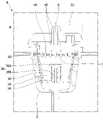
도 3는 본 발명의 일실시예에 따른 음료 캡슐의 구성이 도시된 단면도이다.3 is a cross-sectional view showing the configuration of a beverage capsule according to an embodiment of the present invention.
본 발명의 일실시예에 따른 음료 캡슐은 재료수용공간이 형성되고 내부에 사이폰 튜브(343)가 돌출된 캡슐 바디(342)와, 상기 재료수용공간에 수용되고 상기 사이폰 튜브(343)를 둘러싸도록 배치된 사이폰 캡(340)과, 상기 사이폰 캡(340) 보다 크게 형성되고, 상기 캡슐 바디(342)와 결합되어 상기 재료수용공간을 차폐하는 실링 바디(341)를 포함할 수 있다.The beverage capsule according to an embodiment of the present invention has a material receiving space formed therein and a
상기 사이폰 튜브(343)는 캡슐 바디(342) 하판의 중심 부분에서 연장 형성된 원통 형상의 구조물이며, 상기 사이폰 튜브(343)의 중심 부분은 관통된 상태로 형성되어 물과 음료 재료의 혼합물이 통과할 수 있는 개구부(347)가 마련될 수 있다.The siphon
상기 사이폰 캡(340)은 상기 사이폰 튜브(343)를 둘러싸도록 형성되며, 상기 사이폰 캡(340)과 상기 사이폰 튜브(343) 사이에는 물과 음료의 혼합물이 흐를 수 있는 소정의 공간이 마련될 수 있다. 상기 사이폰 캡(340)은 상기 사이폰 튜브(343) 보다 크게 형성되는 원통형의 측면판(340B)과, 상기 측면판(340B)의 상면에 결합되어 상기 측면판(340B)을 고정시키는 원형의 상판(340A)으로 구성될 수 있다.The siphon
그리고, 상기 캡슐 바디(342)의 하판에는 상기 캡슐 바디(342)와 분리 가능하게 결합되면서 상기 사이폰 튜브의 하단을 막는 사이폰 마개(345)를 더 포함할 수 있다. 상기 사이폰 마개(345)는 상기 사이폰 튜브(343)보다 큰 판체(345A)와, 상기 판체(345A)에서 돌출되고 상기 사이폰 튜브(343)로 내삽되어 끼움되는 돌기(345B)를 포함할 수 있다.And, the lower plate of the
상기 사이폰 마개(345)는 음료 캡슐 내부의 음료 재료가 새어나가는 것을 방지하기 위해 마련되는 것으로, 음료 캡슐이 캡슐 수용부에 내삽되는 때에 상기 사이폰 튜브(343)의 하부에 해당되는 캡슐 바디(342)로부터 제거될 수 있다. 또한, 상기 사이폰 마개(345)의 탈부착으로 인해 캡슐 바디(342)로부터 물과 음료 재료의 혼합물이 빠져나가는 경로가 용이하게 마련될 수 있다.The siphon
상기 캡슐 바디(342)의 하판에는 상기 사이폰 캡(340)의 하단을 상기 캡슐 바디의 하판과 이격되게 지지하는 복수개의 지지부(344)가 마련될 수 있다. 상기 사이폰 캡(340)에서 원통형의 측면판(340B)의 하단부가 상기 지지부(344)에 안착될 수 있으며, 상기 지지부(344)는 상기 사이폰 튜브(343)의 하면의 둘레를 따라 복수개가 형성될 수 있다. 따라서, 각각의 지지부(344)는 서로 이격되어 형성될 수 있으며, 상기 복수개의 지지부(344) 사이에는 틈이 형성될 수 있다. 상기 틈을 통해서 물과 음료 재료의 혼합물이 사이폰 튜브(343)와 사이폰 캡(340) 사이의 공간으로 유입될 수 있다.A plurality of
상기 사이폰 캡(340)에서 상판(340A)의 상면은 상기 실링 바디(341)의 저면을 향하도록 배치될 수 있다. 그리고, 상기 실링 바디(341)는 상기 사이폰 캡(340)의 상면을 차폐하는 제1 차폐부(341A)와, 상기 캡슐 바디(342)에 결합되는 둘레부(341C)와, 상기 제1 차폐부(341A)와 상기 둘레부(341C) 사이에 형성되어 상기 사이폰 캡(340)과 캡슐 바디(342) 사이의 틈을 차폐하는 제2 차폐부(341B)를 포함하여 형성될 수 있다.In the siphon
상기 실링 바디(341)의 하면은 원형으로 형성될 수 있으며, 이에 상기 제1 차폐부(341A)는 원형으로 형성될 수 있고, 상기 제2 차폐부(341B)는 상기 제1 차폐부(341A)를 둘러싸는 고리형상으로 형성될 수 있으며, 상기 둘레부(341C)는 상기 제2 차폐부(341B)를 둘러싸는 고리형상으로 형성될 수 있다.The lower surface of the sealing
그리고, 상기 사이폰 캡(340)의 상면 또한 원형으로 형성될 수 있다. 상기 실링 바디(342) 하면의 직경은 상기 사이폰 캡(340) 상면의 직경보다 크게 형성될 수 있으며, 이에 상기 실링 바디(342)가 상기 사이폰 캡(340)을 완전히 덮도록 형성될 수 있다.In addition, the upper surface of the siphon
따라서, 상기 사이폰 캡(340)은 상기 캡슐 바디(342) 내부에 안정적으로 장착될 수 있으며, 상기 캡슐 바디(342)의 하부 방향으로 사이폰 작용이 일어나도록 배치될 수 있다.Accordingly, the siphon
도 4는 도 3에 개시된 음료 캡슐이 반전되었을 때의 단면도이다.Figure 4 is a cross-sectional view when the beverage capsule disclosed in Figure 3 is inverted.
음료 캡슐은 음료 제조기에 삽입되기 전에 이동과 유통 또는 보관과정에서 도 4와 같이 뒤집어진 상태가 유지될 수 있다. 이러한 상태에서 음료 캡슐 내부에 마련된 사이폰 캡(340)이 상기 사이폰 튜브(343)로부터 이탈되면, 음료 캡슐이 음료 제조기에 삽입된 후 사이폰 캡(340)에 의한 사이폰 효과를 얻지 못하게 된다.The beverage capsule may be maintained in an inverted state as shown in FIG. 4 during movement and distribution or storage before being inserted into the beverage maker. In this state, when the siphon
따라서, 실시예의 음료 캡슐에서 상기 사이폰 튜브(343)의 상단과 상기 실링 바디(341)의 저면 사이의 거리(L1)는 상기 사이폰 캡(340)의 높이(L2) 보다 짧게 형성될 수 있다. 여기서, L1은 음료 캡슐이 뒤집어진 상태로 보았을 때 사이폰 튜브(343)의 최하단면과 상기 실링 바디(341)의 상면 사이의 거리이며, L2는 음료 캡슐이 뒤집어진 상태로 보았을 때 사이폰 튜브(340)에서 측면판(340A)의 최상단면과 상판(340B)의 하면 사이의 거리를 의미할 수 있다.Therefore, in the beverage capsule of the embodiment, the distance L1 between the upper end of the siphon
상술한 바와 같이 상기 사이폰 캡(340)의 위치는 상기 사이폰 튜브(343)의 상단을 벗어나지 못하도록 형성되기 때문에, 상기 사이폰 캡(340)은 음료 캡슐이 흔들리거나 뒤집어지는 경우에도 상기 사이폰 튜브(343)를 따라 상하 방향으로만 움직이도록 고정될 수 있다. 즉, 실시예의 음료 캡슐은 음료 제조기에 투입될 시에 사이폰 캡(340)이 상기 사이폰 튜브(343)를 이탈하지 않으며, 상기 사이폰 튜브(343)를 둘러싸며 상기 복수개의 지지부(344)에 정확히 안착될 수 있도록 형성될 수 있다.As described above, since the position of the siphon
도 5 내지 도 9는 음료 캡슐을 음료 제조기에 투입하고 음료 제조를 위한 과정을 수행하는 흐름을 나타낸 도면이다.5 to 9 are views showing the flow of inserting the beverage capsule into the beverage maker and performing a process for beverage production.
우선 도 5를 참조하면, 도 3에 개시된 음료 캡슐의 사이폰 마개가 분리된 단면도이다. 실시예의 음료 캡슐은 캡슐 바디(342)의 하판에 음료 재료 및 물이 빠져나오기 위한 개구부(347)가 마련될 수 있다. 상기 개구부(347)는 사이폰 튜브(343)의 사이 공간을 의미한다. 음료 캡슐이 음료 제조기에 투입되기 전 보관 상태에서는 음료 캡슐 내부에 담긴 음료 재료가 새어나오는 것을 방지하기 위해 사이폰 마개(345)가 마련될 수 있으며, 기존과 같이 음료 캡슐의 하면을 뚫는 방식과는 달리 본 실시예는 사이폰 마개(345)를 제거함으로써, 음료 재료 및 물의 혼합물이 흘러나가는 경로를 더욱 용이하게 확보할 수 있다.Referring to FIG. 5 first, it is a cross-sectional view in which the siphon stopper of the beverage capsule disclosed in FIG. 3 is separated. The beverage capsule of the embodiment may be provided with an
상기 사이폰 마개(345)는 음료 캡슐을 음료 제조기에 투입하기 바로 전에 제거되는 것이 바람직하다.The siphon
도 6은 도 3에 개시된 음료 캡슐이 음료 제조기에 투입된 상태를 나타낸 단면도이다.6 is a cross-sectional view showing a state in which the beverage capsule disclosed in FIG. 3 is put into the beverage maker.
도 6을 참조하면, 사이폰 마개(345)가 제거된 음료 캡슐은 음료 제조기 내부의 캡슐 수용부에 투입될 수 있다. 도 2에 개시된 바와 같이, 재료 공급기(3)는 음료 제조기의 대략 중앙 상부에 위치되게 설치될 수 있고, 사용자는 재료 공급기(3)의 리드 모듈(37)을 상측으로 회전시켜 복수개의 캡슐 수용부(31)가 드러나도록 한 후에 음료 캡슐(C)을 장착할 수 있다.Referring to FIG. 6 , the beverage capsule from which the siphon
도 7은 도 6에 개시된 음료 캡슐의 상면이 천공된 상태를 나타낸 단면도이다. 도 7을 참조하면, 캡슐 수용부(31)로 음료 캡슐(C)이 투입되고 나면 사용자는 재료 공급기(3)의 리드 모듈(37)을 하측으로 회전시켜 재료 공급기(3)의 내부를 밀폐할 수 있다.7 is a cross-sectional view showing a state in which the upper surface of the beverage capsule disclosed in FIG. 6 is perforated. 7, after the beverage capsule (C) is put into the
리드 모듈(37)을 하측으로 회전되면, 캡슐 수용부(31) 상에는 리드(38)에 설치된 급수바디(41)가 배치될 수 있다. 도면상에는 하나의 캡슐 수용부와 급수 바디를 설명하나, 캡슐 수용부와 급수 바디는 복수개로 형성될 수 있고 그 배치 위치가 상이하나 그 각각의 상세구조가 동일할 수 있다.When the
급수바디(41)의 저면에는 음료 캡슐의 실링 바디(341)를 천공하기 위한 복수의 어퍼 천공부(441)와, 캡슐 컨테이너(31)를 향해 물을 안내하는 급수홀(442)이 형성될 수 있다.A plurality of
재료 공급기(3)의 리드 모듈(37)을 하측으로 회전시켜 재료 공급기(3)의 내부를 밀폐하게 되면, 음료 캡슐의 실링 바디(341) 상면은 상기 복수의 어퍼 천공부(441)에 의해 천공될 수 있다. 음료 제조기의 리드모듈(37)을 닫는 동작만으로 음료 캡슐 캡슐(C)의 실링 바디(341)를 손쉽게 천공 및 절개시킬 수 있다.When the
도 8은 도 7에 개시된 음료 캡슐 내부로 물이 유입된 상태를 나타낸 단면도이다. 도 8을 참조하면, 복수의 급수홀(442)은 급수바디(41)의 저면에 소정 크기의 홀(hole) 형태로 형성될 수 있으며, 실링 바디(341)가 천공된 후, 급수바디(41) 및 복수의 급수홀(442)를 통해 물이 유입되어 캡슐(C)의 내부로 안내될 수 있다.8 is a cross-sectional view showing a state in which water is introduced into the beverage capsule disclosed in FIG. 7 . Referring to FIG. 8 , the plurality of
음료 캡슐 내부로 안내된 물은, 실링 바디(341)의 천공된 공간을 통해 음료 캡슐 내부의 음료 재료와 혼합되면서 수위가 점차 높아지게 된다. 음료 캡슐 내부로 안내되는 물은 음료 재료와 혼합되면서 사이폰 튜브(343)와 사이폰 캡(340) 사이의 공간으로 유입되면서 수위가 점차 높아지게 되고, 사이폰 캡(340) 외부의 수위가 상기 사이폰 튜브(343) 보다 높아지게 되면, 상기 사이폰 튜브(343)의 상면으로 물이 흘러들어가게 되면서 사이폰 현상이 일어날 수 있다. 즉, 수위가 사이폰 캡(340)의 높이보다 높아지면 사이폰 튜브 사이의 개구부(347)를 통해 물, 음료 재료 또는 이의 혼합물이 연속적으로 빠져나갈 수 있으며, 이는 캡슐 수용부 출구채널(312)을 통해 추출될 수 있다.The water level guided into the beverage capsule is gradually increased while being mixed with the beverage material inside the beverage capsule through the perforated space of the sealing
상기와 같이 본 발명은 사이폰 효과를 이용하여 혼합물이 추출될 수 있도록 유도함으로써, 캡슐 바디 또는 실링 바디에 음료 재료의 취출을 위한 별도의 홀을 천공하는 경우 보다 신뢰성이 높게 음료 재료를 추출할 수 있는 이점이 있다.As described above, the present invention induces the mixture to be extracted using the siphon effect, so that when a separate hole for taking out the beverage material is drilled in the capsule body or the sealing body, the beverage material can be extracted more reliably there is an advantage
도 9는 도 8에 개시된 음료 캡슐 내부에서 물과 액체 재료가 빠져나간 상태를 나타낸 단면도이다. 도 8에서와 같이 복수의 급수홀(442)로부터 캡슐 바디(342) 내부로 물이 급수되고 물과 음료 재료가 혼합된 혼합물의 수위가 사이폰 튜브의 상면보다 높아지면 사이폰 작용이 일어나게 된다.Figure 9 is a cross-sectional view showing a state in which water and liquid material escaped from the inside of the beverage capsule disclosed in Figure 8. As shown in FIG. 8, when water is supplied into the
사이폰 작용이 일어나면, 캡슐 바디(342) 내부에 차있던 혼합물은 수위가 0이 되는 시점까지 사이폰 캡(340)과 사이폰 튜브(343) 사이의 공간으로 모두 빨려올라가 사이폰 튜브 내부의 개구부(347)를 통해 모두 배출될 수 있다.When the siphon action occurs, the mixture filled in the
실시예와 같은 음료 캡슐을 구비한 음료 제조기는 사이폰 캡을 이용한 사이폰 원리를 이용하여 음료 캡슐에 포함된 음료 재료의 혼합물이 음료 캡슐 내부에 잔존하지 않고 모두 배출되어 음료 제조에 사용될 수 있다.Beverage maker having a beverage capsule as in the embodiment can be used in beverage production by using the siphon principle using a siphon cap, the mixture of beverage materials contained in the beverage capsule is discharged without remaining in the beverage capsule.
한편, 본 발명에 기재된 메인유로(2), 급수유로(4), 음료 취출유로(61), 가스 취출유로(71), 에어 주입유로(81), 에어 공급유로(154) 등의 유로는 유체가 통과할 수 있는 호스나 튜브에 의해 형성될 수 있고, 길이방향으로 연속되는 복수개의 호스나 복수개의 튜브로 구성되는 것도 가능하고, 조절밸브 등의 타 구성을 사이에 두고 배치되는 2개의 호스나 튜브를 포함하는 것도 가능함은 물론이다.On the other hand, the flow paths of the
이상의 설명은 본 발명의 기술 사상을 예시적으로 설명한 것에 불과한 것으로서, 본 발명이 속하는 기술 분야에서 통상의 지식을 가진 자라면 본 발명의 본질적인 특성에서 벗어나지 않는 범위에서 다양한 수정 및 변형이 가능할 것이다.The above description is merely illustrative of the technical spirit of the present invention, and various modifications and variations will be possible without departing from the essential characteristics of the present invention by those skilled in the art to which the present invention pertains.
따라서, 본 발명에 개시된 실시 예들은 본 발명의 기술 사상을 한정하기 위한 것이 아니라 설명하기 위한 것이고, 이러한 실시 예에 의하여 본 발명의 기술 사상의 범위가 한정되는 것은 아니다.Therefore, the embodiments disclosed in the present invention are not intended to limit the technical spirit of the present invention, but to explain, and the scope of the technical spirit of the present invention is not limited by these embodiments.
본 발명의 보호 범위는 아래의 청구범위에 의하여 해석되어야 하며, 그와 동등한 범위 내에 있는 모든 기술 사상은 본 발명의 권리범위에 포함되는 것으로 해석되어야 할 것이다.The protection scope of the present invention should be construed by the following claims, and all technical ideas within the equivalent range should be construed as being included in the scope of the present invention.
340: 사이폰 캡 341: 실링 바디
342: 캡슐 바디 343: 사이폰 튜브
344: 지지부 345: 사이폰 마개340: siphon cap 341: sealing body
342: capsule body 343: siphon tube
344: support 345: siphon stopper
Claims (10)
Translated fromKorean상기 재료수용공간에 수용되고 상기 사이폰 튜브를 둘러싸도록 배치된 사이폰 캡과,
상기 사이폰 캡 보다 크게 형성되고, 상기 캡슐 바디와 결합되어 상기 재료수용공간을 차폐하는 실링 바디를 포함하고
상기 사이폰 튜브의 상단과 상기 실링바디의 저면 사이의 거리(L1)는 상기 사이폰 캡의 높이(L2) 보다 짧고,
상기 캡슐 바디에는 상기 사이폰 캡의 하단을 상기 캡슐 바디의 하판과 이격되게 지지하는 복수개의 지지부가 돌출된 음료 캡슐.A capsule body having a material accommodating space and a siphon tube protruding therein;
a siphon cap accommodated in the material receiving space and arranged to surround the siphon tube;
It is formed larger than the siphon cap, and includes a sealing body coupled to the capsule body to shield the material accommodating space,
The distance (L1) between the upper end of the siphon tube and the bottom surface of the sealing body is shorter than the height (L2) of the siphon cap,
The capsule body has a plurality of support portions for supporting the lower end of the siphon cap to be spaced apart from the lower plate of the capsule body, protruding beverage capsules.
상기 캡슐 바디의 하판에 분리 가능하게 결합되어 상기 사이폰 튜브의 하단을 막는 사이폰 마개를 더 포함하는 음료 캡슐.The method of claim 1,
Beverage capsule further comprising a siphon stopper detachably coupled to the lower plate of the capsule body to block the lower end of the siphon tube.
상기 사이폰 마개는
상기 사이폰 튜브보다 큰 판체와,
상기 판체에서 돌출되고 상기 사이폰 튜브로 내삽되어 끼움되는 돌기를 포함하는 음료 캡슐.4. The method of claim 3,
The siphon stopper
A plate body larger than the siphon tube,
Beverage capsule comprising a protrusion that protrudes from the plate body and is inserted into the siphon tube to be fitted.
상기 사이폰 캡의 상면은 상기 실링 바디의 저면을 향하는 음료 캡슐.The method of claim 1,
The upper surface of the siphon cap is a beverage capsule facing the lower surface of the sealing body.
상기 실링 바디는 상기 사이폰 캡의 상면을 차폐하는 제1 차폐부와,
상기 캡슐 바디에 결합되는 둘레부와,
상기 제1 차폐부와 상기 둘레부 사이에 형성되어 상기 사이폰 캡과 캡슐 바디의 사이의 틈을 차폐하는 제2차폐부를 포함하는 음료 캡슐.The method of claim 1,
The sealing body includes a first shielding portion for shielding the upper surface of the siphon cap,
a peripheral portion coupled to the capsule body;
A beverage capsule comprising a second shielding portion formed between the first shielding portion and the peripheral portion to shield the gap between the siphon cap and the capsule body.
상기 실링 바디의 하면과 상기 사이폰 캡의 상면 각각은 원형이고,
상기 실링 바디의 직경은 상기 사이폰 캡의 직경보다 큰 음료 캡슐.The method of claim 1,
Each of the lower surface of the sealing body and the upper surface of the siphon cap is circular,
The diameter of the sealing body is larger than the diameter of the siphon cap beverage capsule.
상기 음료 캡슐이 수용되는 음료 캡슐 수용공간이 형성된 재료 공급기를 포함하고,
상기 음료 캡슐은
재료수용공간이 형성되고 내부에 사이폰 튜브가 돌출된 캡슐 바디와,
상기 재료수용공간에 수용되고 상기 사이폰 튜브를 둘러싸도록 배치된 사이폰 캡과,
상기 사이폰 캡 보다 크게 형성되고, 상기 캡슐 바디와 결합되어 상기 재료수용공간을 차폐하는 실링 바디를 포함하고
상기 사이폰 튜브의 상단과 상기 실링바디의 저면 사이의 거리(L1)는 상기 사이폰 캡의 높이(L2) 보다 짧고,
상기 캡슐 바디에는 상기 사이폰 캡의 하단을 상기 캡슐 바디의 하판과 이격되게 지지하는 복수개의 지지부가 돌출된 음료 캡슐을 갖는 음료 제조기.a beverage capsule containing beverage ingredients;
It includes a material feeder having a beverage capsule receiving space in which the beverage capsule is accommodated,
The beverage capsules
A capsule body having a material accommodating space and a siphon tube protruding therein;
a siphon cap accommodated in the material receiving space and arranged to surround the siphon tube;
It is formed larger than the siphon cap, and includes a sealing body coupled to the capsule body to shield the material accommodating space,
The distance (L1) between the upper end of the siphon tube and the bottom surface of the sealing body is shorter than the height (L2) of the siphon cap,
The capsule body has a beverage maker having a plurality of support portions protruding for supporting the lower end of the siphon cap to be spaced apart from the lower plate of the capsule body.
상기 캡슐 바디의 하판에 분리 가능하게 결합되어 상기 사이폰 튜브의 하단을 막는 사이폰 마개를 더 포함하는 음료 캡슐을 갖는 음료 제조기.9. The method of claim 8,
Beverage maker having a beverage capsule further comprising a siphon stopper detachably coupled to the lower plate of the capsule body to block the lower end of the siphon tube.
Priority Applications (1)
| Application Number | Priority Date | Filing Date | Title |
|---|---|---|---|
| KR1020170146918AKR102457236B1 (en) | 2017-11-06 | 2017-11-06 | Beverage maker |
Applications Claiming Priority (1)
| Application Number | Priority Date | Filing Date | Title |
|---|---|---|---|
| KR1020170146918AKR102457236B1 (en) | 2017-11-06 | 2017-11-06 | Beverage maker |
Publications (2)
| Publication Number | Publication Date |
|---|---|
| KR20190051372A KR20190051372A (en) | 2019-05-15 |
| KR102457236B1true KR102457236B1 (en) | 2022-10-21 |
Family
ID=66579816
Family Applications (1)
| Application Number | Title | Priority Date | Filing Date |
|---|---|---|---|
| KR1020170146918AActiveKR102457236B1 (en) | 2017-11-06 | 2017-11-06 | Beverage maker |
Country Status (1)
| Country | Link |
|---|---|
| KR (1) | KR102457236B1 (en) |
Families Citing this family (1)
| Publication number | Priority date | Publication date | Assignee | Title |
|---|---|---|---|---|
| CN113215778B (en)* | 2020-01-21 | 2024-03-15 | 青岛海尔洗衣机有限公司 | Clothes treating agent box and washing machine |
Citations (4)
| Publication number | Priority date | Publication date | Assignee | Title |
|---|---|---|---|---|
| WO1999065373A1 (en)* | 1998-06-17 | 1999-12-23 | Seb S.A. | Filter-holder provided with a beverage spill-proof device, and coffee maker equipped therewith |
| US20050155494A1 (en) | 2002-06-12 | 2005-07-21 | Sara Lee/De N.V. | Apparatus and method for preparing coffee with a fine-bubble froth layer, in particular cappuccino |
| KR101229897B1 (en)* | 2011-04-08 | 2013-03-11 | 주식회사 다인씨앤에프 | Manufacturing method of capsule |
| WO2017137460A1 (en)* | 2016-02-09 | 2017-08-17 | Nestec S.A. | A beverage capsule |
Family Cites Families (1)
| Publication number | Priority date | Publication date | Assignee | Title |
|---|---|---|---|---|
| DE102013215274A1 (en)* | 2013-02-20 | 2014-08-21 | K-Fee System Gmbh | Portion capsule and system |
- 2017
- 2017-11-06KRKR1020170146918Apatent/KR102457236B1/enactiveActive
Patent Citations (4)
| Publication number | Priority date | Publication date | Assignee | Title |
|---|---|---|---|---|
| WO1999065373A1 (en)* | 1998-06-17 | 1999-12-23 | Seb S.A. | Filter-holder provided with a beverage spill-proof device, and coffee maker equipped therewith |
| US20050155494A1 (en) | 2002-06-12 | 2005-07-21 | Sara Lee/De N.V. | Apparatus and method for preparing coffee with a fine-bubble froth layer, in particular cappuccino |
| KR101229897B1 (en)* | 2011-04-08 | 2013-03-11 | 주식회사 다인씨앤에프 | Manufacturing method of capsule |
| WO2017137460A1 (en)* | 2016-02-09 | 2017-08-17 | Nestec S.A. | A beverage capsule |
Also Published As
| Publication number | Publication date |
|---|---|
| KR20190051372A (en) | 2019-05-15 |
Similar Documents
| Publication | Publication Date | Title |
|---|---|---|
| KR102108427B1 (en) | Beer Maker | |
| KR102282446B1 (en) | Baverage maker | |
| KR102434270B1 (en) | Baverage maker and beverage maker cleaning system having the same | |
| KR102380876B1 (en) | Beverage maker | |
| KR102463321B1 (en) | Baverage maker | |
| KR102457236B1 (en) | Beverage maker | |
| KR102734821B1 (en) | Fermentation container and baverage maker having the same | |
| KR102481824B1 (en) | Beverage maker | |
| KR102259341B1 (en) | Beverage maker | |
| KR102223917B1 (en) | Baverage making pack and baverage maker having the same | |
| KR102339174B1 (en) | Beverage maker and control method of the same | |
| KR102307783B1 (en) | Beer maker and Control method of the same | |
| KR102463325B1 (en) | Beverage maker | |
| KR102658905B1 (en) | Baverage maker | |
| KR102481833B1 (en) | Beverage maker | |
| KR20220006882A (en) | Baverage maker | |
| KR102481834B1 (en) | Beverage maker | |
| KR102223915B1 (en) | Baverage maker | |
| KR102397732B1 (en) | Beverage maker and method for making beverage | |
| KR102397153B1 (en) | Beverage maker and control method of the same | |
| KR102288718B1 (en) | Baverage maker | |
| KR102481851B1 (en) | Baverage maker | |
| KR102533780B1 (en) | Baverage maker | |
| KR102396664B1 (en) | Baverage maker | |
| KR102200598B1 (en) | Beverage maker |
Legal Events
| Date | Code | Title | Description |
|---|---|---|---|
| PA0109 | Patent application | St.27 status event code:A-0-1-A10-A12-nap-PA0109 | |
| R17-X000 | Change to representative recorded | St.27 status event code:A-3-3-R10-R17-oth-X000 | |
| PG1501 | Laying open of application | St.27 status event code:A-1-1-Q10-Q12-nap-PG1501 | |
| PN2301 | Change of applicant | St.27 status event code:A-3-3-R10-R13-asn-PN2301 St.27 status event code:A-3-3-R10-R11-asn-PN2301 | |
| A201 | Request for examination | ||
| PA0201 | Request for examination | St.27 status event code:A-1-2-D10-D11-exm-PA0201 | |
| D13-X000 | Search requested | St.27 status event code:A-1-2-D10-D13-srh-X000 | |
| D14-X000 | Search report completed | St.27 status event code:A-1-2-D10-D14-srh-X000 | |
| E902 | Notification of reason for refusal | ||
| PE0902 | Notice of grounds for rejection | St.27 status event code:A-1-2-D10-D21-exm-PE0902 | |
| E13-X000 | Pre-grant limitation requested | St.27 status event code:A-2-3-E10-E13-lim-X000 | |
| P11-X000 | Amendment of application requested | St.27 status event code:A-2-2-P10-P11-nap-X000 | |
| P13-X000 | Application amended | St.27 status event code:A-2-2-P10-P13-nap-X000 | |
| E701 | Decision to grant or registration of patent right | ||
| PE0701 | Decision of registration | St.27 status event code:A-1-2-D10-D22-exm-PE0701 | |
| GRNT | Written decision to grant | ||
| PR0701 | Registration of establishment | St.27 status event code:A-2-4-F10-F11-exm-PR0701 | |
| PR1002 | Payment of registration fee | St.27 status event code:A-2-2-U10-U11-oth-PR1002 Fee payment year number:1 | |
| PG1601 | Publication of registration | St.27 status event code:A-4-4-Q10-Q13-nap-PG1601 | |
| PR1001 | Payment of annual fee | St.27 status event code:A-4-4-U10-U11-oth-PR1001 Fee payment year number:4 |