KR102453048B1 - Cartridge with electronics compartment for an aerosol delivery device and related assembly method - Google Patents
Cartridge with electronics compartment for an aerosol delivery device and related assembly methodDownload PDFInfo
- Publication number
- KR102453048B1 KR102453048B1KR1020167035806AKR20167035806AKR102453048B1KR 102453048 B1KR102453048 B1KR 102453048B1KR 1020167035806 AKR1020167035806 AKR 1020167035806AKR 20167035806 AKR20167035806 AKR 20167035806AKR 102453048 B1KR102453048 B1KR 102453048B1
- Authority
- KR
- South Korea
- Prior art keywords
- flow director
- cartridge
- base
- outer body
- reservoir substrate
- Prior art date
- Legal status (The legal status is an assumption and is not a legal conclusion. Google has not performed a legal analysis and makes no representation as to the accuracy of the status listed.)
- Active
Links
- 239000000443aerosolSubstances0.000titleclaimsabstractdescription202
- 238000000034methodMethods0.000titleclaimsabstractdescription95
- 239000000758substrateSubstances0.000claimsabstractdescription123
- 238000010438heat treatmentMethods0.000claimsdescription129
- 239000002243precursorSubstances0.000claimsdescription97
- 239000000203mixtureSubstances0.000claimsdescription77
- 230000008878couplingEffects0.000claimsdescription54
- 238000010168coupling processMethods0.000claimsdescription54
- 238000005859coupling reactionMethods0.000claimsdescription54
- 238000003466weldingMethods0.000claimsdescription35
- 239000006199nebulizerSubstances0.000claimsdescription26
- 125000006850spacer groupChemical group0.000claimsdescription8
- DNIAPMSPPWPWGF-UHFFFAOYSA-NPropylene glycolChemical compoundCC(O)CODNIAPMSPPWPWGF-UHFFFAOYSA-N0.000description33
- 239000000463materialSubstances0.000description32
- 239000003570airSubstances0.000description29
- 239000007788liquidSubstances0.000description28
- 241000208125NicotianaSpecies0.000description24
- 235000002637Nicotiana tabacumNutrition0.000description24
- 230000007246mechanismEffects0.000description22
- 239000000796flavoring agentSubstances0.000description21
- PEDCQBHIVMGVHV-UHFFFAOYSA-NGlycerineChemical compoundOCC(O)COPEDCQBHIVMGVHV-UHFFFAOYSA-N0.000description20
- 230000000391smoking effectEffects0.000description20
- SNICXCGAKADSCV-JTQLQIEISA-N(-)-NicotineChemical compoundCN1CCC[C@H]1C1=CC=CN=C1SNICXCGAKADSCV-JTQLQIEISA-N0.000description18
- 229960002715nicotineDrugs0.000description18
- SNICXCGAKADSCV-UHFFFAOYSA-NnicotineNatural productsCN1CCCC1C1=CC=CN=C1SNICXCGAKADSCV-UHFFFAOYSA-N0.000description18
- 235000013355food flavoring agentNutrition0.000description14
- 235000019504cigarettesNutrition0.000description12
- XLYOFNOQVPJJNP-UHFFFAOYSA-NwaterSubstancesOXLYOFNOQVPJJNP-UHFFFAOYSA-N0.000description12
- 238000004891communicationMethods0.000description11
- 239000000047productSubstances0.000description11
- 238000007789sealingMethods0.000description11
- 239000012530fluidSubstances0.000description10
- 235000011187glycerolNutrition0.000description10
- 235000019506cigarNutrition0.000description9
- 238000005516engineering processMethods0.000description9
- 230000036961partial effectEffects0.000description9
- 230000008569processEffects0.000description9
- 230000002829reductive effectEffects0.000description8
- 239000000126substanceSubstances0.000description8
- 230000001276controlling effectEffects0.000description7
- 235000019634flavorsNutrition0.000description7
- 238000009472formulationMethods0.000description7
- 229910052751metalInorganic materials0.000description7
- 239000002184metalSubstances0.000description7
- 239000004033plasticSubstances0.000description7
- 229920003023plasticPolymers0.000description7
- 239000000779smokeSubstances0.000description7
- 239000007787solidSubstances0.000description7
- 239000003571electronic cigaretteSubstances0.000description6
- NOOLISFMXDJSKH-UHFFFAOYSA-NDL-mentholNatural productsCC(C)C1CCC(C)CC1ONOOLISFMXDJSKH-UHFFFAOYSA-N0.000description5
- 238000010521absorption reactionMethods0.000description5
- 239000000853adhesiveSubstances0.000description5
- 230000001070adhesive effectEffects0.000description5
- 230000008901benefitEffects0.000description5
- YXTPWUNVHCYOSP-UHFFFAOYSA-Nbis($l^{2}-silanylidene)molybdenumChemical compound[Si]=[Mo]=[Si]YXTPWUNVHCYOSP-UHFFFAOYSA-N0.000description5
- 238000009833condensationMethods0.000description5
- 230000005494condensationEffects0.000description5
- 230000006870functionEffects0.000description5
- 229940041616mentholDrugs0.000description5
- 229910001220stainless steelInorganic materials0.000description5
- 239000010935stainless steelSubstances0.000description5
- 239000011800void materialSubstances0.000description5
- NOOLISFMXDJSKH-UTLUCORTSA-N(+)-NeomentholChemical compoundCC(C)[C@@H]1CC[C@@H](C)C[C@@H]1ONOOLISFMXDJSKH-UTLUCORTSA-N0.000description4
- JOOXCMJARBKPKM-UHFFFAOYSA-N4-oxopentanoic acidChemical compoundCC(=O)CCC(O)=OJOOXCMJARBKPKM-UHFFFAOYSA-N0.000description4
- LCTONWCANYUPML-UHFFFAOYSA-NPyruvic acidChemical compoundCC(=O)C(O)=OLCTONWCANYUPML-UHFFFAOYSA-N0.000description4
- 238000002485combustion reactionMethods0.000description4
- 238000010276constructionMethods0.000description4
- 239000000284extractSubstances0.000description4
- 239000007789gasSubstances0.000description4
- 230000006698inductionEffects0.000description4
- 239000004615ingredientSubstances0.000description4
- 238000003780insertionMethods0.000description4
- 230000037431insertionEffects0.000description4
- JVTAAEKCZFNVCJ-UHFFFAOYSA-Nlactic acidChemical compoundCC(O)C(O)=OJVTAAEKCZFNVCJ-UHFFFAOYSA-N0.000description4
- 150000007524organic acidsChemical class0.000description4
- 239000000565sealantSubstances0.000description4
- 238000003860storageMethods0.000description4
- OKTJSMMVPCPJKN-UHFFFAOYSA-NCarbonChemical compound[C]OKTJSMMVPCPJKN-UHFFFAOYSA-N0.000description3
- KDYFGRWQOYBRFD-UHFFFAOYSA-NSuccinic acidNatural productsOC(=O)CCC(O)=OKDYFGRWQOYBRFD-UHFFFAOYSA-N0.000description3
- 230000002745absorbentEffects0.000description3
- 239000002250absorbentSubstances0.000description3
- 229910052782aluminiumInorganic materials0.000description3
- 230000015572biosynthetic processEffects0.000description3
- 239000000919ceramicSubstances0.000description3
- 230000007797corrosionEffects0.000description3
- 238000005260corrosionMethods0.000description3
- 238000010586diagramMethods0.000description3
- 239000003292glueSubstances0.000description3
- 229910002804graphiteInorganic materials0.000description3
- 239000010439graphiteSubstances0.000description3
- 230000000670limiting effectEffects0.000description3
- 238000004519manufacturing processMethods0.000description3
- 229910021344molybdenum silicideInorganic materials0.000description3
- 238000000465mouldingMethods0.000description3
- 230000002441reversible effectEffects0.000description3
- 230000035807sensationEffects0.000description3
- 235000019615sensationsNutrition0.000description3
- 230000001953sensory effectEffects0.000description3
- 238000000926separation methodMethods0.000description3
- 239000004593EpoxySubstances0.000description2
- LYCAIKOWRPUZTN-UHFFFAOYSA-NEthylene glycolChemical compoundOCCOLYCAIKOWRPUZTN-UHFFFAOYSA-N0.000description2
- 244000246386Mentha pulegiumSpecies0.000description2
- 235000016257Mentha pulegiumNutrition0.000description2
- 235000004357Mentha x piperitaNutrition0.000description2
- XAGFODPZIPBFFR-UHFFFAOYSA-NaluminiumChemical compound[Al]XAGFODPZIPBFFR-UHFFFAOYSA-N0.000description2
- 239000011111cardboardSubstances0.000description2
- 229920002301cellulose acetatePolymers0.000description2
- 150000001875compoundsChemical class0.000description2
- 238000013461designMethods0.000description2
- 230000005674electromagnetic inductionEffects0.000description2
- CBOQJANXLMLOSS-UHFFFAOYSA-Nethyl vanillinChemical groupCCOC1=CC(C=O)=CC=C1OCBOQJANXLMLOSS-UHFFFAOYSA-N0.000description2
- 230000005294ferromagnetic effectEffects0.000description2
- 239000003302ferromagnetic materialSubstances0.000description2
- 239000000835fiberSubstances0.000description2
- 238000005429filling processMethods0.000description2
- 239000011888foilSubstances0.000description2
- 235000011389fruit/vegetable juiceNutrition0.000description2
- 239000011521glassSubstances0.000description2
- 230000020169heat generationEffects0.000description2
- 235000001050hortel pimentaNutrition0.000description2
- 239000004310lactic acidSubstances0.000description2
- 235000014655lactic acidNutrition0.000description2
- 239000010410layerSubstances0.000description2
- 229940040102levulinic acidDrugs0.000description2
- 230000005291magnetic effectEffects0.000description2
- 238000012986modificationMethods0.000description2
- 230000004048modificationEffects0.000description2
- 229910021343molybdenum disilicideInorganic materials0.000description2
- 230000003287optical effectEffects0.000description2
- 235000005985organic acidsNutrition0.000description2
- 239000000123paperSubstances0.000description2
- 230000000704physical effectEffects0.000description2
- 238000000197pyrolysisMethods0.000description2
- 229940107700pyruvic acidDrugs0.000description2
- 230000000717retained effectEffects0.000description2
- 230000000007visual effectEffects0.000description2
- NOOLISFMXDJSKH-KXUCPTDWSA-N(-)-MentholChemical compoundCC(C)[C@@H]1CC[C@@H](C)C[C@H]1ONOOLISFMXDJSKH-KXUCPTDWSA-N0.000description1
- 241000208140AcerSpecies0.000description1
- 244000144730Amygdalus persicaSpecies0.000description1
- 241000167854Bourreria succulentaSpecies0.000description1
- 244000223760Cinnamomum zeylanicumSpecies0.000description1
- 241000207199CitrusSpecies0.000description1
- 235000008733Citrus aurantifoliaNutrition0.000description1
- 235000005979Citrus limonNutrition0.000description1
- 244000131522Citrus pyriformisSpecies0.000description1
- 235000016623Fragaria vescaNutrition0.000description1
- 240000009088Fragaria x ananassaSpecies0.000description1
- 235000011363Fragaria x ananassaNutrition0.000description1
- 240000004670Glycyrrhiza echinataSpecies0.000description1
- 235000001453Glycyrrhiza echinataNutrition0.000description1
- 235000006200Glycyrrhiza glabraNutrition0.000description1
- 235000017382Glycyrrhiza lepidotaNutrition0.000description1
- 235000010254Jasminum officinaleNutrition0.000description1
- 240000005385Jasminum sambacSpecies0.000description1
- 244000255365KaskarillabaumSpecies0.000description1
- 244000165082Lavanda veraSpecies0.000description1
- 235000010663Lavandula angustifoliaNutrition0.000description1
- 235000011430Malus pumilaNutrition0.000description1
- 244000070406Malus silvestrisSpecies0.000description1
- 235000015103Malus silvestrisNutrition0.000description1
- 235000006679Mentha X verticillataNutrition0.000description1
- 235000014749Mentha crispaNutrition0.000description1
- 244000078639Mentha spicataSpecies0.000description1
- 235000002899Mentha suaveolensNutrition0.000description1
- 235000001636Mentha x rotundifoliaNutrition0.000description1
- 235000009421Myristica fragransNutrition0.000description1
- 244000270834Myristica fragransSpecies0.000description1
- 240000009023Myrrhis odorataSpecies0.000description1
- 235000007265Myrrhis odorataNutrition0.000description1
- 235000012550Pimpinella anisumNutrition0.000description1
- 235000006040Prunus persica var persicaNutrition0.000description1
- 240000000513Santalum albumSpecies0.000description1
- 235000008632Santalum albumNutrition0.000description1
- 235000016639Syzygium aromaticumNutrition0.000description1
- 244000223014Syzygium aromaticumSpecies0.000description1
- 244000269722Thea sinensisSpecies0.000description1
- 235000009470Theobroma cacaoNutrition0.000description1
- 244000299461Theobroma cacaoSpecies0.000description1
- 235000011941Tilia x europaeaNutrition0.000description1
- 235000006886Zingiber officinaleNutrition0.000description1
- 244000273928Zingiber officinaleSpecies0.000description1
- 230000002378acidificating effectEffects0.000description1
- 239000004676acrylonitrile butadiene styreneSubstances0.000description1
- 230000009471actionEffects0.000description1
- 239000004480active ingredientSubstances0.000description1
- 238000012387aerosolizationMethods0.000description1
- 239000012080ambient airSubstances0.000description1
- 150000001412aminesChemical class0.000description1
- 150000003863ammonium saltsChemical class0.000description1
- 230000006399behaviorEffects0.000description1
- 238000005452bendingMethods0.000description1
- 230000009286beneficial effectEffects0.000description1
- KDYFGRWQOYBRFD-NUQCWPJISA-Nbutanedioic acidChemical compoundO[14C](=O)CC[14C](O)=OKDYFGRWQOYBRFD-NUQCWPJISA-N0.000description1
- 239000006227byproductSubstances0.000description1
- 239000003990capacitorSubstances0.000description1
- 230000001413cellular effectEffects0.000description1
- 239000003795chemical substances by applicationSubstances0.000description1
- 235000019693cherriesNutrition0.000description1
- 230000001055chewing effectEffects0.000description1
- 235000015111chewsNutrition0.000description1
- 235000017803cinnamonNutrition0.000description1
- 235000020971citrus fruitsNutrition0.000description1
- 238000004040coloringMethods0.000description1
- 239000002131composite materialSubstances0.000description1
- 238000007906compressionMethods0.000description1
- 230000006835compressionEffects0.000description1
- 235000008504concentrateNutrition0.000description1
- 239000012141concentrateSubstances0.000description1
- 239000000356contaminantSubstances0.000description1
- 239000006071creamSubstances0.000description1
- 238000002788crimpingMethods0.000description1
- 238000013500data storageMethods0.000description1
- 238000001514detection methodMethods0.000description1
- 230000001627detrimental effectEffects0.000description1
- 229940079593drugDrugs0.000description1
- 239000003814drugSubstances0.000description1
- 238000012377drug deliveryMethods0.000description1
- 235000013399edible fruitsNutrition0.000description1
- 229940073505ethyl vanillinDrugs0.000description1
- 238000001704evaporationMethods0.000description1
- 230000008020evaporationEffects0.000description1
- 239000011152fibreglassSubstances0.000description1
- 239000007792gaseous phaseSubstances0.000description1
- 235000008397gingerNutrition0.000description1
- 235000019534high fructose corn syrupNutrition0.000description1
- 235000012907honeyNutrition0.000description1
- WGCNASOHLSPBMP-UHFFFAOYSA-NhydroxyacetaldehydeNatural productsOCC=OWGCNASOHLSPBMP-UHFFFAOYSA-N0.000description1
- 230000006872improvementEffects0.000description1
- 230000003993interactionEffects0.000description1
- 229910000953kanthalInorganic materials0.000description1
- 229960000448lactic acidDrugs0.000description1
- 239000001102lavandula veraSubstances0.000description1
- 235000018219lavenderNutrition0.000description1
- 229940010454licoriceDrugs0.000description1
- 239000004571limeSubstances0.000description1
- 239000008263liquid aerosolSubstances0.000description1
- 230000014759maintenance of locationEffects0.000description1
- 230000013011matingEffects0.000description1
- 150000002739metalsChemical class0.000description1
- OSWPMRLSEDHDFF-UHFFFAOYSA-Nmethyl salicylateChemical compoundCOC(=O)C1=CC=CC=C1OOSWPMRLSEDHDFF-UHFFFAOYSA-N0.000description1
- 230000006855networkingEffects0.000description1
- 229910001120nichromeInorganic materials0.000description1
- 239000001702nutmegSubstances0.000description1
- 238000011017operating methodMethods0.000description1
- 239000011087paperboardSubstances0.000description1
- 239000002245particleSubstances0.000description1
- 239000004417polycarbonateSubstances0.000description1
- 229920000515polycarbonatePolymers0.000description1
- 229920005862polyolPolymers0.000description1
- 150000003077polyolsChemical class0.000description1
- 238000012545processingMethods0.000description1
- QQONPFPTGQHPMA-UHFFFAOYSA-NpropyleneNatural productsCC=CQQONPFPTGQHPMA-UHFFFAOYSA-N0.000description1
- 125000004805propylene groupChemical group[H]C([H])([H])C([H])([*:1])C([H])([H])[*:2]0.000description1
- 230000001105regulatory effectEffects0.000description1
- 230000029058respiratory gaseous exchangeEffects0.000description1
- 235000002020sageNutrition0.000description1
- 239000002356single layerSubstances0.000description1
- 239000007779soft materialSubstances0.000description1
- 239000007921spraySubstances0.000description1
- 238000006467substitution reactionMethods0.000description1
- 239000001384succinic acidSubstances0.000description1
- 150000005846sugar alcoholsPolymers0.000description1
- 239000000725suspensionSubstances0.000description1
- 235000020357syrupNutrition0.000description1
- 239000006188syrupSubstances0.000description1
- 238000012546transferMethods0.000description1
- 230000001131transforming effectEffects0.000description1
- 230000007723transport mechanismEffects0.000description1
- 238000009834vaporizationMethods0.000description1
- 230000008016vaporizationEffects0.000description1
- 239000003039volatile agentSubstances0.000description1
- 238000004804windingMethods0.000description1
- 239000009637wintergreen oilSubstances0.000description1
Images


Classifications
- A—HUMAN NECESSITIES
- A24—TOBACCO; CIGARS; CIGARETTES; SIMULATED SMOKING DEVICES; SMOKERS' REQUISITES
- A24B—MANUFACTURE OR PREPARATION OF TOBACCO FOR SMOKING OR CHEWING; TOBACCO; SNUFF
- A24B15/00—Chemical features or treatment of tobacco; Tobacco substitutes, e.g. in liquid form
- A24B15/10—Chemical features of tobacco products or tobacco substitutes
- A24B15/16—Chemical features of tobacco products or tobacco substitutes of tobacco substitutes
- A24B15/167—Chemical features of tobacco products or tobacco substitutes of tobacco substitutes in liquid or vaporisable form, e.g. liquid compositions for electronic cigarettes
- A—HUMAN NECESSITIES
- A24—TOBACCO; CIGARS; CIGARETTES; SIMULATED SMOKING DEVICES; SMOKERS' REQUISITES
- A24F—SMOKERS' REQUISITES; MATCH BOXES; SIMULATED SMOKING DEVICES
- A24F40/00—Electrically operated smoking devices; Component parts thereof; Manufacture thereof; Maintenance or testing thereof; Charging means specially adapted therefor
- A24F40/40—Constructional details, e.g. connection of cartridges and battery parts
- A24F40/42—Cartridges or containers for inhalable precursors
- A—HUMAN NECESSITIES
- A24—TOBACCO; CIGARS; CIGARETTES; SIMULATED SMOKING DEVICES; SMOKERS' REQUISITES
- A24F—SMOKERS' REQUISITES; MATCH BOXES; SIMULATED SMOKING DEVICES
- A24F40/00—Electrically operated smoking devices; Component parts thereof; Manufacture thereof; Maintenance or testing thereof; Charging means specially adapted therefor
- A24F40/40—Constructional details, e.g. connection of cartridges and battery parts
- A24F40/48—Fluid transfer means, e.g. pumps
- A24F40/485—Valves; Apertures
- A—HUMAN NECESSITIES
- A24—TOBACCO; CIGARS; CIGARETTES; SIMULATED SMOKING DEVICES; SMOKERS' REQUISITES
- A24F—SMOKERS' REQUISITES; MATCH BOXES; SIMULATED SMOKING DEVICES
- A24F47/00—Smokers' requisites not otherwise provided for
- A—HUMAN NECESSITIES
- A61—MEDICAL OR VETERINARY SCIENCE; HYGIENE
- A61M—DEVICES FOR INTRODUCING MEDIA INTO, OR ONTO, THE BODY; DEVICES FOR TRANSDUCING BODY MEDIA OR FOR TAKING MEDIA FROM THE BODY; DEVICES FOR PRODUCING OR ENDING SLEEP OR STUPOR
- A61M11/00—Sprayers or atomisers specially adapted for therapeutic purposes
- A61M11/04—Sprayers or atomisers specially adapted for therapeutic purposes operated by the vapour pressure of the liquid to be sprayed or atomised
- A61M11/041—Sprayers or atomisers specially adapted for therapeutic purposes operated by the vapour pressure of the liquid to be sprayed or atomised using heaters
- A61M11/042—Sprayers or atomisers specially adapted for therapeutic purposes operated by the vapour pressure of the liquid to be sprayed or atomised using heaters electrical
- A—HUMAN NECESSITIES
- A61—MEDICAL OR VETERINARY SCIENCE; HYGIENE
- A61M—DEVICES FOR INTRODUCING MEDIA INTO, OR ONTO, THE BODY; DEVICES FOR TRANSDUCING BODY MEDIA OR FOR TAKING MEDIA FROM THE BODY; DEVICES FOR PRODUCING OR ENDING SLEEP OR STUPOR
- A61M15/00—Inhalators
- A61M15/06—Inhaling appliances shaped like cigars, cigarettes or pipes
- F—MECHANICAL ENGINEERING; LIGHTING; HEATING; WEAPONS; BLASTING
- F22—STEAM GENERATION
- F22B—METHODS OF STEAM GENERATION; STEAM BOILERS
- F22B1/00—Methods of steam generation characterised by form of heating method
- F22B1/28—Methods of steam generation characterised by form of heating method in boilers heated electrically
- F22B1/284—Methods of steam generation characterised by form of heating method in boilers heated electrically with water in reservoirs
- H—ELECTRICITY
- H05—ELECTRIC TECHNIQUES NOT OTHERWISE PROVIDED FOR
- H05B—ELECTRIC HEATING; ELECTRIC LIGHT SOURCES NOT OTHERWISE PROVIDED FOR; CIRCUIT ARRANGEMENTS FOR ELECTRIC LIGHT SOURCES, IN GENERAL
- H05B1/00—Details of electric heating devices
- H05B1/02—Automatic switching arrangements specially adapted to apparatus ; Control of heating devices
- H05B1/0227—Applications
- H05B1/0297—Heating of fluids for non specified applications
- H—ELECTRICITY
- H05—ELECTRIC TECHNIQUES NOT OTHERWISE PROVIDED FOR
- H05B—ELECTRIC HEATING; ELECTRIC LIGHT SOURCES NOT OTHERWISE PROVIDED FOR; CIRCUIT ARRANGEMENTS FOR ELECTRIC LIGHT SOURCES, IN GENERAL
- H05B3/00—Ohmic-resistance heating
- H05B3/40—Heating elements having the shape of rods or tubes
- H05B3/42—Heating elements having the shape of rods or tubes non-flexible
- H05B3/46—Heating elements having the shape of rods or tubes non-flexible heating conductor mounted on insulating base
- A—HUMAN NECESSITIES
- A24—TOBACCO; CIGARS; CIGARETTES; SIMULATED SMOKING DEVICES; SMOKERS' REQUISITES
- A24F—SMOKERS' REQUISITES; MATCH BOXES; SIMULATED SMOKING DEVICES
- A24F40/00—Electrically operated smoking devices; Component parts thereof; Manufacture thereof; Maintenance or testing thereof; Charging means specially adapted therefor
- A24F40/10—Devices using liquid inhalable precursors
- A—HUMAN NECESSITIES
- A24—TOBACCO; CIGARS; CIGARETTES; SIMULATED SMOKING DEVICES; SMOKERS' REQUISITES
- A24F—SMOKERS' REQUISITES; MATCH BOXES; SIMULATED SMOKING DEVICES
- A24F40/00—Electrically operated smoking devices; Component parts thereof; Manufacture thereof; Maintenance or testing thereof; Charging means specially adapted therefor
- A24F40/50—Control or monitoring
- A—HUMAN NECESSITIES
- A61—MEDICAL OR VETERINARY SCIENCE; HYGIENE
- A61M—DEVICES FOR INTRODUCING MEDIA INTO, OR ONTO, THE BODY; DEVICES FOR TRANSDUCING BODY MEDIA OR FOR TAKING MEDIA FROM THE BODY; DEVICES FOR PRODUCING OR ENDING SLEEP OR STUPOR
- A61M2205/00—General characteristics of the apparatus
- A61M2205/50—General characteristics of the apparatus with microprocessors or computers
- A61M2205/502—User interfaces, e.g. screens or keyboards
- A61M2205/505—Touch-screens; Virtual keyboard or keypads; Virtual buttons; Soft keys; Mouse touches
- A—HUMAN NECESSITIES
- A61—MEDICAL OR VETERINARY SCIENCE; HYGIENE
- A61M—DEVICES FOR INTRODUCING MEDIA INTO, OR ONTO, THE BODY; DEVICES FOR TRANSDUCING BODY MEDIA OR FOR TAKING MEDIA FROM THE BODY; DEVICES FOR PRODUCING OR ENDING SLEEP OR STUPOR
- A61M2205/00—General characteristics of the apparatus
- A61M2205/58—Means for facilitating use, e.g. by people with impaired vision
- A61M2205/581—Means for facilitating use, e.g. by people with impaired vision by audible feedback
- A—HUMAN NECESSITIES
- A61—MEDICAL OR VETERINARY SCIENCE; HYGIENE
- A61M—DEVICES FOR INTRODUCING MEDIA INTO, OR ONTO, THE BODY; DEVICES FOR TRANSDUCING BODY MEDIA OR FOR TAKING MEDIA FROM THE BODY; DEVICES FOR PRODUCING OR ENDING SLEEP OR STUPOR
- A61M2205/00—General characteristics of the apparatus
- A61M2205/58—Means for facilitating use, e.g. by people with impaired vision
- A61M2205/583—Means for facilitating use, e.g. by people with impaired vision by visual feedback
- A—HUMAN NECESSITIES
- A61—MEDICAL OR VETERINARY SCIENCE; HYGIENE
- A61M—DEVICES FOR INTRODUCING MEDIA INTO, OR ONTO, THE BODY; DEVICES FOR TRANSDUCING BODY MEDIA OR FOR TAKING MEDIA FROM THE BODY; DEVICES FOR PRODUCING OR ENDING SLEEP OR STUPOR
- A61M2205/00—General characteristics of the apparatus
- A61M2205/82—Internal energy supply devices
- A61M2205/8206—Internal energy supply devices battery-operated
Landscapes
- Engineering & Computer Science (AREA)
- Health & Medical Sciences (AREA)
- Life Sciences & Earth Sciences (AREA)
- Anesthesiology (AREA)
- Biomedical Technology (AREA)
- Heart & Thoracic Surgery (AREA)
- Hematology (AREA)
- Animal Behavior & Ethology (AREA)
- General Health & Medical Sciences (AREA)
- Public Health (AREA)
- Veterinary Medicine (AREA)
- Pulmonology (AREA)
- Bioinformatics & Cheminformatics (AREA)
- Sustainable Development (AREA)
- Thermal Sciences (AREA)
- Mechanical Engineering (AREA)
- General Engineering & Computer Science (AREA)
- Physics & Mathematics (AREA)
- Sustainable Energy (AREA)
- Chemical & Material Sciences (AREA)
- Chemical Kinetics & Catalysis (AREA)
- General Chemical & Material Sciences (AREA)
- Disinfection, Sterilisation Or Deodorisation Of Air (AREA)
- Containers And Packaging Bodies Having A Special Means To Remove Contents (AREA)
- Catching Or Destruction (AREA)
- Electrostatic Spraying Apparatus (AREA)
Abstract
Translated fromKoreanDescription
Translated fromKorean본 발명은 에어로졸 송달 장치에 관한 것이며, 보다 구체적으로는 밀봉된 카트리지를 구비하는 에어로졸 송달 장치에 관한 것이다. 에어로졸 송달 장치는 에어로졸 전구체를 가열하도록 구성된 가열 요소를 포함하는 분무기를 구비한다. 담배로부터 제조 또는 유래되는 성분을 구비하거나 그렇지 않으면 담배를 포함할 수 있는 에어로졸 전구체는 사람이 소비하기 위한 흡입 가능한 물질을 생산하기 위해 분무기에 의해 가열된다.The present invention relates to aerosol delivery devices, and more particularly to aerosol delivery devices having a sealed cartridge. The aerosol delivery device comprises a nebulizer comprising a heating element configured to heat the aerosol precursor. Aerosol precursors, which have ingredients made or derived from tobacco, or which may otherwise include tobacco, are heated by a nebulizer to produce an inhalable substance for human consumption.
사용을 위해 담배 연소를 요구하는 흡연 제품의 개선 또는 대안으로서 많은 흡연 장치가 오랜 세월 동안 제안되었다. 이들 장치의 대다수는 의도적으로, 담배의 연소에 기인하는 상당한 양의 불완전 연소 및 열분해 생성물을 산출하지 않으면서 궐련(cigarette), 여송연(cigar) 또는 파이프 흡연과 연관된 감각을 제공하도록 설계되었다. 이 목적을 위해, 휘발성 물질을 기화 또는 가열하기 위해 전기 에너지를 사용하거나, 상당한 정도의 담배 연소 없이 궐련, 여송연, 또는 파이프 흡연의 감각을 제공하려는 다수의 흡연 제품, 향미 발생기 및 의약용 흡입기가 제안되었다. 예를 들어, 그 전체가 본 명세서에 참조로 원용되는, Robinson 등의 미국 특허 제7,726,320호, Griffith 2세 등의 미국 특허 공개 제2013/0255702호, Sebastian 등의 미국 특허 공개 제2014/0000638호, Collett 등의 미국 특허 공개 제2014/0060554호, Sears 등의 2012년 10월 8일자 미국 특허 출원 제13/647,000호, Ampolini 등의 2013년 3월 14일자 미국 특허 출원 제13/826,929호, Davis 등의 2013년 8월 28일자 미국 특허 출원 제14/01 1,992호에 기재된 배경기술에 제시되어 있는 다양한 대체 흡연 물품, 에어로졸 송달 장치, 및 발열 소스를 참조하기 바란다.Many smoking devices have been proposed over the years as an improvement or alternative to smoking products requiring tobacco burning for use. Many of these devices are intentionally designed to provide the sensations associated with smoking a cigarette, cigar, or pipe without producing significant amounts of incomplete combustion and pyrolysis products attributable to combustion of the tobacco. For this purpose, a number of smoking products, flavor generators and medicinal inhalers have been proposed which use electrical energy to vaporize or heat volatiles, or which provide the sensation of smoking a cigarette, cigar, or pipe without significant tobacco burning. became For example, U.S. Patent No. 7,726,320 to Robinson et al., U.S. Patent Publication No. 2013/0255702 to Griffith II et al., U.S. Patent Publication No. 2014/0000638 to Sebastian et al., which are incorporated herein by reference in their entirety; US Patent Publication No. 2014/0060554 to Collett et al., US Patent Application Serial No. 13/647,000, filed Oct. 8, 2012 by Sears et al., US Patent Application Serial No. 13/826,929, filed Mar. 14, 2013 to Ampolini et al., Davis et al. See the various alternative smoking articles, aerosol delivery devices, and heat sources set forth in the background described in U.S. Patent Application Serial No. 14/01 1,992, filed August 28, 2013, to
에어로졸 송달 장치의 특정 기존 실시예는 제어 보디 및 카트리지를 구비한다. 제어 보디에는 전원(예를 들어 배터리)이 배치될 수 있으며 카트리지에는 에어로졸 전구체 조성물이 배치될 수 있다. 그러나, 에어로졸 전구체 조성물은 특히 카트리지의 충전 중에 카트리지로부터 누설되는 경향이 있을 수 있다.Certain existing embodiments of aerosol delivery devices have a control body and a cartridge. A power source (eg, a battery) may be disposed in the control body and an aerosol precursor composition may be disposed in the cartridge. However, the aerosol precursor composition may be prone to leakage from the cartridge, particularly during charging of the cartridge.
따라서, 누설에 저항하거나 아니면 그 성능을 개선하는 에어로졸 송달 장치용 카트리지 및 그 조립 방법의 구성에 관한 진전이 바람직할 수 있다.Accordingly, advances in the construction of cartridges and methods of assembling the same for aerosol delivery devices that resist leakage or otherwise improve their performance would be desirable.
본 발명은 특정 실시예에서 전자 담배로 특징지어질 수 있는 에어로졸 송달 장치에 관한 것이다. 일 양태에서는 에어로졸 송달 장치용 카트리지가 제공된다. 카트리지는 외부 보디, 상기 외부 보디에 결합되는 유동 디렉터(director), 상기 유동 디렉터에 결합되는 베이스, 및 상기 외부 보디 내에 수용되는 분무기를 구비할 수 있다. 상기 유동 디렉터와 상기 외부 보디는 저장조 구획을 형성할 수 있으며 상기 유동 디렉터와 상기 베이스는 전자기기 구획을 형성한다.The present invention relates in certain embodiments to an aerosol delivery device that may be characterized as an electronic cigarette. In one aspect, a cartridge for an aerosol delivery device is provided. The cartridge may have an outer body, a flow director coupled to the outer body, a base coupled to the flow director, and a nebulizer received within the outer body. The flow director and the outer body may define a reservoir compartment and the flow director and the base form an electronics compartment.
일부 실시예에서, 상기 카트리지는 저장조 구획에서의 저장조 기판을 추가로 구비할 수 있다. 상기 저장조 기판은 그 제 1 및 제 2 단부 사이에 갭이 형성되도록 유동 디렉터 주위에 부분적으로 래핑될 수 있다. 상기 저장조 기판은 유동 디렉터 주위에 적어도 부분적으로 래핑될 수 있으며, 유동 디렉터에 형성되고 그로부터 연장되는 다수의 돌출부와 결합될 수 있다. 상기 유동 디렉터에는 리세스가 형성될 수 있다. 상기 리세스는 유동 디렉터와 저장조 기판 사이에 채널을 형성할 수 있다.In some embodiments, the cartridge may further include a reservoir substrate in the reservoir compartment. The reservoir substrate may be partially wrapped around the flow director such that a gap is formed between its first and second ends. The reservoir substrate may be at least partially wrapped around the flow director and may engage a plurality of protrusions formed on and extending from the flow director. A recess may be formed in the flow director. The recess may form a channel between the flow director and the reservoir substrate.
일부 실시예에서, 상기 카트리지는 유동 디렉터 내에 성형되고 베이스의 커넥터 단부로 연장되는 하나 이상의 가열 단자를 추가로 구비할 수 있다. 상기 카트리지는 전자기기 구획 내에 배치되는 전자 제어 부품 및 상기 전자 제어 부품으로부터 베이스의 커넥터 단부로 연장되는 제어 부품 단자를 추가로 구비할 수 있다. 상기 베이스는 외부 보디의 내표면에 대해 밀봉하도록 구성된 변형 가능한 리브(rib)를 가질 수 있다. 상기 유동 디렉터는 외부 보디의 내표면에 대해 밀봉하도록 구성된 변형 가능한 리브를 가질 수 있다.In some embodiments, the cartridge may further include one or more heating terminals molded into the flow director and extending to the connector end of the base. The cartridge may further include an electronic control component disposed within the electronics compartment and a control component terminal extending from the electronic control component to a connector end of the base. The base may have deformable ribs configured to seal against the inner surface of the outer body. The flow director may have deformable ribs configured to seal against an inner surface of the outer body.
일부 실시예에서 상기 유동 디렉터는 외부 보디에 용접될 수 있다. 상기 유동 디렉터는 또한 베이스에 용접될 수 있다. 상기 카트리지는 유동 디렉터로부터 베이스를 통한 공기 유동에 저항하도록 구성된 일방 밸브를 추가로 구비할 수 있다. 상기 일방 밸브는 플랩 밸브와 크로스-밸브로 구성되는 그룹에서 선택될 수 있다. 상기 일방 밸브는 전자기기 구획에 배치될 수 있다. 상기 카트리지는 베이스와 대향하는 그 단부에서 외부 보디에 결합되는 마우쓰피스를 추가로 구비할 수 있다. 상기 마우쓰피스는 외부 보디 내의 빈 체적을 감소시키도록 구성된 연장부를 가질 수 있다. 상기 마우쓰피스와 상기 분무기 사이에 스페이서가 배치될 수 있다. 상기 스페이서는 외부 보디 내의 빈 체적을 감소시키도록 구성될 수 있다. 상기 마우쓰피스는 채널을 형성하는 립(lip)을 구비할 수 있다. 상기 립과 상기 채널은 마우쓰피스를 통해서 형성된 개구 주위로 연장될 수 있다.In some embodiments, the flow director may be welded to the outer body. The flow director may also be welded to the base. The cartridge may further include a one-way valve configured to resist air flow from the flow director through the base. The one-way valve may be selected from the group consisting of a flap valve and a cross-valve. The one-way valve may be disposed in the electronics compartment. The cartridge may further include a mouthpiece coupled to the outer body at its end opposite the base. The mouthpiece may have an extension configured to reduce an empty volume within the outer body. A spacer may be disposed between the mouthpiece and the atomizer. The spacer may be configured to reduce an empty volume within the outer body. The mouthpiece may have a lip forming a channel. The lip and the channel may extend around an opening formed through the mouthpiece.
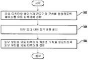
추가 양태에서는 에어로졸 송달 장치용 카트리지 조립 방법이 제공된다. 이 방법은 유동 디렉터와 베이스가 전자기기 구획을 형성하도록 베이스를 유동 디렉터에 결합시키는 단계, 외부 보디 내에 분무기를 배치하는 단계, 및 외부 보디와 유동 디렉터가 저장조 구획을 형성하도록 외부 보디를 유동 디렉터에 결합시키는 단계를 포함할 수 있다.In a further aspect, a method of assembling a cartridge for an aerosol delivery device is provided. The method includes coupling a base to the flow director such that the flow director and the base form an electronics compartment, placing the atomizer within the outer body, and attaching the outer body to the flow director such that the outer body and the flow director form a reservoir compartment. bonding may be included.
일부 실시예에서 상기 방법은 에어로졸 전구체 조성물을 저장하도록 구성된 저장조 기판을 유동 디렉터 주위에 적어도 부분적으로 래핑하는 단계 및 저장조 기판을 저장조 구획 내에 배치하는 단계를 추가로 포함할 수 있다. 저장조 기판을 유동 디렉터 주위에 적어도 부분적으로 래핑하는 단계는 저장조 기판을 유동 디렉터에 형성되고 그로부터 연장되는 다수의 돌출부와 결합시키는 단계를 포함할 수 있다. 또한, 저장조 기판을 유동 디렉터 주위에 적어도 부분적으로 래핑하는 단계는 저장조 기판을 그 제 1 및 제 2 단부 사이에 갭이 형성되도록 유동 디렉터 주위에 부분적으로 래핑하는 단계를 포함할 수 있다. 저장조 기판을 유동 디렉터 주위에 적어도 부분적으로 래핑하는 단계는 또한 유동 디렉터에 형성된 절취부에서 유동 디렉터와 저장조 기판 사이에 채널을 형성하는 단계를 포함할 수 있다. 일부 실시예에서 상기 방법은 유동 디렉터 내에 하나 이상의 가열 단자를 성형하는 단계를 추가로 포함할 수 있다. 상기 방법은 에어로졸 전구체 조성물을 유동 디렉터에 형성된 절취부에서 저장조 기판의 제 1 및 제 2 단부 사이의 갭과 유동 디렉터와 저장조 기판 사이의 채널 중 적어도 하나로 인도함으로써 저장조 기판을 에어로졸 전구체 조성물로 충전하는 단계를 추가로 포함할 수 있다.In some embodiments the method may further comprise at least partially wrapping a reservoir substrate configured to store the aerosol precursor composition around the flow director and placing the reservoir substrate within the reservoir compartment. At least partially wrapping the reservoir substrate about the flow director may include engaging the reservoir substrate with a plurality of protrusions formed on and extending from the flow director. Further, at least partially wrapping the reservoir substrate about the flow director may include partially wrapping the reservoir substrate about the flow director such that a gap is formed between the first and second ends thereof. At least partially wrapping the reservoir substrate around the flow director may also include forming a channel between the flow director and the reservoir substrate in a cutout formed in the flow director. In some embodiments, the method may further comprise forming one or more heating terminals within the flow director. The method includes filling the reservoir substrate with the aerosol precursor composition by directing the aerosol precursor composition into at least one of a gap between the first and second ends of the reservoir substrate in a cutout formed in the flow director and a channel between the flow director and the reservoir substrate. may further include.
일부 실시예에서 상기 방법은 전자기기 구획에 전자 제어 부품을 배치하는 단계 및 전자 제어 부품에 제어 부품 단자를 연결하는 단계를 추가로 포함할 수 있다. 외부 보디를 유동 디렉터에 결합시키는 단계는 유동 디렉터의 변형 가능한 리브를 외부 보디의 내표면에 대해 변형시키는 단계를 포함할 수 있다. 외부 보디를 유동 디렉터에 결합시키는 단계는 외부 보디를 유동 디렉터에 용접하는 단계를 포함할 수 있다. 상기 방법은 외부 보디를 베이스에 결합시키는 단계를 추가로 포함할 수 있다. 외부 보디를 베이스에 결합시키는 단계는 베이스의 변형 가능한 리브를 외부 보디의 내표면에 대해 변형시키는 단계를 포함할 수 있다. 베이스를 유동 디렉터에 결합시키는 단계는 베이스를 유동 디렉터에 용접하는 단계를 포함할 수 있다. 또한, 상기 방법은 베이스에 일방 밸브를 결합시키는 단계를 포함할 수 있다. 일방 밸브는 유동 디렉터로부터 베이스를 통한 공기 유동에 저항하도록 구성될 수 있다.In some embodiments, the method may further include placing an electronic control component in the electronics compartment and connecting the control component terminal to the electronic control component. Coupling the outer body to the flow director may include deforming deformable ribs of the flow director relative to an inner surface of the outer body. Coupling the outer body to the flow director may include welding the outer body to the flow director. The method may further comprise coupling the outer body to the base. Coupling the outer body to the base may include deforming the deformable ribs of the base relative to the inner surface of the outer body. Coupling the base to the flow director may include welding the base to the flow director. The method may also include coupling the one-way valve to the base. The one-way valve may be configured to resist air flow from the flow director through the base.
추가 양태에서는 에어로졸 송달 장치용 카트리지가 제공된다. 상기 카트리지는 외부 보디, 상기 외부 보디 내에 적어도 부분적으로 수용되는 분무기, 상기 외부 보디 내에 적어도 부분적으로 수용되는 유동 디렉터, 및 상기 분무기에 결합되고 유동 디렉터를 통해서 적어도 부분적으로 연장되는 다수의 가열 단자를 구비할 수 있다.In a further aspect, a cartridge for an aerosol delivery device is provided. The cartridge has an outer body, an atomizer at least partially housed within the outer body, a flow director at least partially housed within the outer body, and a plurality of heating terminals coupled to the atomizer and extending at least partially through the flow director. can do.
일부 실시예에서, 상기 가열 단자는 유동 디렉터 내에 성형될 수 있다. 상기 카트리지는 베이스를 추가로 구비할 수 있다. 상기 베이스는 외부 보디와 유동 디렉터 중 적어도 하나에 결합될 수 있다. 상기 유동 디렉터와 상기 외부 보디는 저장조 구획을 형성할 수 있으며 상기 유동 디렉터와 상기 베이스는 전자기기 구획을 형성할 수 있다.In some embodiments, the heating terminal may be molded into the flow director. The cartridge may further include a base. The base may be coupled to at least one of an external body and a flow director. The flow director and the outer body may form a reservoir compartment and the flow director and the base may form an electronics compartment.
본 발명은 제한 없이 하기 실시예들을 포함한다.The present invention includes, without limitation, the following examples.
실시예 1: 에어로졸 송달 장치용 카트리지이며,Example 1: A cartridge for an aerosol delivery device,
외부 보디;external body;
상기 외부 보디에 결합되는 유동 디렉터;a flow director coupled to the outer body;
상기 유동 디렉터에 결합되는 베이스; 및a base coupled to the flow director; and
상기 외부 보디 내에 수용되는 분무기를 포함하고;a nebulizer housed within the outer body;
상기 유동 디렉터와 상기 외부 보디는 저장조 구획을 형성하며 상기 유동 디렉터와 상기 베이스는 전자기기 구획을 형성한다.The flow director and the outer body form a reservoir compartment and the flow director and the base form an electronics compartment.
실시예 2: 임의의 선행 또는 후속 실시예의 카트리지에 있어서, 상기 저장조 구획에서의 저장조 기판을 추가로 포함한다.Embodiment 2: The cartridge of any preceding or subsequent embodiment, further comprising a reservoir substrate in said reservoir compartment.
실시예 3: 임의의 선행 또는 후속 실시예의 카트리지에 있어서, 상기 저장조 기판은 그 제 1 및 제 2 단부 사이에 갭이 형성되도록 유동 디렉터 주위에 부분적으로 래핑된다.Embodiment 3: The cartridge of any preceding or subsequent embodiment, wherein the reservoir substrate is partially wrapped around the flow director such that a gap is formed between first and second ends thereof.
실시예 4: 임의의 선행 또는 후속 실시예의 카트리지에 있어서, 상기 저장조 기판은 유동 디렉터 주위에 적어도 부분적으로 래핑되며, 유동 디렉터에 형성되고 그로부터 연장되는 다수의 돌출부와 결합된다.Embodiment 4: The cartridge of any preceding or subsequent embodiment, wherein the reservoir substrate is at least partially wrapped around the flow director and is engaged with a plurality of protrusions formed on and extending from the flow director.
실시예 5: 임의의 선행 또는 후속 실시예의 카트리지에 있어서, 상기 유동 디렉터에는 리세스가 형성되며, 상기 리세스는 유동 디렉터와 저장조 기판 사이에 채널을 형성한다.Embodiment 5: The cartridge of any preceding or subsequent embodiment, wherein the flow director is formed with a recess, the recess forming a channel between the flow director and the reservoir substrate.
실시예 6: 임의의 선행 또는 후속 실시예의 카트리지에 있어서, 상기 유동 디렉터 내에 성형되고 베이스의 커넥터 단부로 연장되는 하나 이상의 가열 단자를 추가로 포함한다.Embodiment 6: The cartridge of any preceding or subsequent embodiment, further comprising one or more heating terminals molded into the flow director and extending to a connector end of the base.
실시예 7: 임의의 선행 또는 후속 실시예의 카트리지에 있어서, 상기 전자기기 구획 내에 배치되는 전자 제어 부품 및 상기 전자 제어 부품으로부터 베이스의 커넥터 단부로 연장되는 제어 부품 단자를 추가로 포함한다.Embodiment 7: The cartridge of any preceding or subsequent embodiment, further comprising an electronic control component disposed within the electronics compartment and a control component terminal extending from the electronic control component to a connector end of the base.
실시예 8: 임의의 선행 또는 후속 실시예의 카트리지에 있어서, 상기 베이스는 외부 보디의 내표면에 대해 밀봉하도록 구성된 변형 가능한 리브를 갖는다.Embodiment 8 The cartridge of any preceding or subsequent embodiment, wherein the base has deformable ribs configured to seal against an inner surface of the outer body.
실시예 9: 임의의 선행 또는 후속 실시예의 카트리지에 있어서, 상기 유동 디렉터는 외부 보디의 내표면에 대해 밀봉하도록 구성된 변형 가능한 리브를 갖는다.Embodiment 9: The cartridge of any preceding or subsequent embodiment, wherein the flow director has deformable ribs configured to seal against an inner surface of the outer body.
실시예 10: 임의의 선행 또는 후속 실시예의 카트리지에 있어서, 상기 유동 디렉터는 외부 보디와 베이스 중 하나 또는 양자에 용접된다.Embodiment 10 The cartridge of any preceding or subsequent embodiment, wherein the flow director is welded to one or both of the outer body and the base.
실시예 11: 임의의 선행 또는 후속 실시예의 카트리지에 있어서, 유동 디렉터로부터 베이스를 통한 공기 유동에 저항하도록 구성된 일방 밸브를 추가로 포함한다.Embodiment 11: The cartridge of any preceding or subsequent embodiment, further comprising a one-way valve configured to resist air flow from the flow director through the base.
실시예 12: 임의의 선행 또는 후속 실시예의 카트리지에 있어서, 상기 일방 밸브는 플랩 밸브와 크로스-밸브로 구성되는 그룹에서 선택된다.Embodiment 12 The cartridge of any preceding or subsequent embodiment, wherein the one-way valve is selected from the group consisting of a flap valve and a cross-valve.
실시예 13: 임의의 선행 또는 후속 실시예의 카트리지에 있어서, 상기 일방 밸브는 전자기기 구획에 배치된다.
실시예 14: 임의의 선행 또는 후속 실시예의 카트리지에 있어서, 베이스와 대향하는 그 단부에서 외부 보디에 결합되는 마우쓰피스를 추가로 포함한다.Embodiment 14 The cartridge of any preceding or subsequent embodiment, further comprising a mouthpiece coupled to the outer body at its end opposite the base.
실시예 15: 임의의 선행 또는 후속 실시예의 카트리지에 있어서, 상기 마우쓰피스는 외부 보디 내의 빈 체적을 감소시키도록 구성된 연장부를 갖는다.
실시예 16: 임의의 선행 또는 후속 실시예의 카트리지에 있어서, 상기 마우쓰피스와 상기 분무기 사이에 스페이서가 배치되며, 상기 스페이서는 외부 보디 내의 빈 체적을 감소시키도록 구성된다.Embodiment 16 The cartridge of any preceding or subsequent embodiment, wherein a spacer is disposed between the mouthpiece and the atomizer, the spacer configured to reduce an empty volume within the outer body.
실시예 17: 임의의 선행 또는 후속 실시예의 카트리지에 있어서, 상기 마우쓰피스는 채널을 형성하는 립을 포함하며, 상기 립과 상기 채널은 마우쓰피스를 통해서 형성된 개구 주위로 연장된다.Embodiment 17 The cartridge of any preceding or subsequent embodiment, wherein the mouthpiece comprises a lip defining a channel, the lip and the channel extending around an opening formed through the mouthpiece.
실시예 18: 에어로졸 송달 장치용 카트리지 조립 방법이며, 상기 방법은:Example 18: A method of assembling a cartridge for an aerosol delivery device, the method comprising:
유동 디렉터와 베이스가 전자기기 구획을 형성하도록 베이스를 유동 디렉터에 결합시키는 단계;coupling the base to the flow director such that the flow director and the base form an electronics compartment;
외부 보디 내에 분무기를 배치하는 단계; 및placing the nebulizer within the outer body; and
외부 보디와 유동 디렉터가 저장조 구획을 형성하도록 외부 보디를 유동 디렉터에 결합시키는 단계를 포함한다.coupling the outer body to the flow director such that the outer body and the flow director form a reservoir compartment.
실시예 19: 임의의 선행 또는 후속 실시예의 방법에 있어서, 에어로졸 전구체 조성물을 저장하도록 구성된 저장조 기판을 유동 디렉터 주위에 적어도 부분적으로 래핑하는 단계; 및Example 19 The method of any preceding or subsequent embodiment, comprising: at least partially wrapping a reservoir substrate configured to store the aerosol precursor composition around the flow director; and
저장조 기판을 저장조 구획 내에 배치하는 단계를 추가로 포함한다.and placing the reservoir substrate within the reservoir compartment.
실시예 20: 임의의 선행 또는 후속 실시예의 방법에 있어서, 저장조 기판을 유동 디렉터 주위에 적어도 부분적으로 래핑하는 단계는 저장조 기판을 유동 디렉터에 형성되고 그로부터 연장되는 다수의 돌출부와 결합시키는 단계를 포함한다.Embodiment 20 The method of any preceding or subsequent embodiment, wherein at least partially wrapping the reservoir substrate around the flow director comprises engaging the reservoir substrate with a plurality of protrusions formed on and extending from the flow director. .
실시예 21: 임의의 선행 또는 후속 실시예의 방법에 있어서, 저장조 기판을 유동 디렉터 주위에 적어도 부분적으로 래핑하는 단계는 저장조 기판을 그 제 1 및 제 2 단부 사이에 갭이 형성되도록 유동 디렉터 주위에 부분적으로 래핑하는 단계를 포함한다.Embodiment 21 The method of any preceding or subsequent embodiment, wherein at least partially wrapping the reservoir substrate around the flow director comprises wrapping the reservoir substrate partially around the flow director such that a gap is formed between the first and second ends thereof. wrapping with
실시예 22: 임의의 선행 또는 후속 실시예의 방법에 있어서, 저장조 기판을 유동 디렉터 주위에 적어도 부분적으로 래핑하는 단계는 유동 디렉터에 형성된 절취부에서 유동 디렉터와 저장조 기판 사이에 채널을 형성하는 단계를 포함한다.Embodiment 22 The method of any preceding or subsequent embodiment, wherein at least partially wrapping the reservoir substrate around the flow director comprises forming a channel between the flow director and the reservoir substrate in a cutout formed in the flow director do.
실시예 23: 임의의 선행 또는 후속 실시예의 방법에 있어서, 에어로졸 전구체 조성물을 유동 디렉터에 형성된 절취부에서 저장조 기판의 제 1 및 제 2 단부 사이의 갭과 유동 디렉터와 저장조 기판 사이의 채널 중 적어도 하나로 인도함으로써 저장조 기판을 에어로졸 전구체 조성물로 충전하는 단계를 추가로 포함한다.Embodiment 23 The method of any preceding or subsequent embodiment, wherein the aerosol precursor composition is introduced into at least one of a gap between the first and second ends of the reservoir substrate in a cutout formed in the flow director and a channel between the flow director and the reservoir substrate. and filling the reservoir substrate with the aerosol precursor composition by delivering.
실시예 24: 임의의 선행 또는 후속 실시예의 방법에 있어서, 유동 디렉터 내에 하나 이상의 가열 단자를 성형하는 단계를 추가로 포함한다.Embodiment 24 The method of any preceding or subsequent embodiment, further comprising forming one or more heating terminals within the flow director.
실시예 25: 임의의 선행 또는 후속 실시예의 방법에 있어서, 전자기기 구획에 전자 제어 부품을 배치하는 단계; 및Embodiment 25 The method of any preceding or subsequent embodiment, further comprising: placing an electronic control component in an electronics compartment; and
전자 제어 부품에 제어 부품 단자를 연결하는 단계를 추가로 포함한다.and connecting the control component terminal to the electronic control component.
실시예 26: 임의의 선행 또는 후속 실시예의 방법에 있어서, 외부 보디를 유동 디렉터에 결합시키는 단계는 유동 디렉터의 변형 가능한 리브를 외부 보디의 내표면에 대해 변형시키는 단계를 포함한다.Embodiment 26 The method of any preceding or subsequent embodiment, wherein coupling the outer body to the flow director comprises deforming deformable ribs of the flow director relative to an inner surface of the outer body.
실시예 27: 임의의 선행 또는 후속 실시예의 방법에 있어서, 외부 보디를 유동 디렉터에 결합시키는 단계는 외부 보디를 유동 디렉터에 용접하는 단계를 포함한다.Embodiment 27 The method of any preceding or subsequent embodiment, wherein coupling the outer body to the flow director comprises welding the outer body to the flow director.
실시예 28: 임의의 선행 또는 후속 실시예의 방법에 있어서, 외부 보디를 베이스에 결합시키는 단계를 추가로 포함하며,Embodiment 28: The method of any preceding or subsequent embodiment, further comprising coupling the outer body to the base,
외부 보디를 베이스에 결합시키는 단계는 베이스의 변형 가능한 리브를 외부 보디의 내표면에 대해 변형시키는 단계를 포함한다.Coupling the outer body to the base includes deforming the deformable ribs of the base relative to the inner surface of the outer body.
실시예 29: 임의의 선행 또는 후속 실시예의 방법에 있어서, 베이스를 유동 디렉터에 결합시키는 단계는 베이스를 유동 디렉터에 용접하는 단계를 포함한다.Embodiment 29 The method of any preceding or subsequent embodiment, wherein coupling the base to the flow director comprises welding the base to the flow director.
실시예 30: 임의의 선행 또는 후속 실시예의 방법에 있어서, 베이스에 일방 밸브를 결합시키는 단계를 추가로 포함하며, 상기 일방 밸브는 유동 디렉터로부터 베이스를 통한 공기 유동에 저항하도록 구성된다.Embodiment 30 The method of any preceding or subsequent embodiment, further comprising coupling a one-way valve to the base, wherein the one-way valve is configured to resist air flow from the flow director through the base.
실시예 31: 에어로졸 송달 장치용 카트리지이며,Example 31: A cartridge for an aerosol delivery device,
외부 보디;external body;
상기 외부 보디 내에 적어도 부분적으로 수용되는 분무기;an atomizer at least partially housed within the outer body;
상기 외부 보디 내에 적어도 부분적으로 수용되는 유동 디렉터; 및a flow director at least partially housed within the outer body; and
상기 분무기에 결합되고 유동 디렉터를 통해서 적어도 부분적으로 연장되는 다수의 가열 단자를 포함한다.and a plurality of heating terminals coupled to the atomizer and extending at least partially through the flow director.
실시예 32: 임의의 선행 또는 후속 실시예의 카트리지에 있어서, 상기 가열 단자는 유동 디렉터 내에 성형된다.Embodiment 32 The cartridge of any preceding or subsequent embodiment, wherein the heating terminal is molded into the flow director.
실시예 33: 임의의 선행 또는 후속 실시예의 카트리지에 있어서, 베이스를 추가로 포함하며, 상기 베이스는 외부 보디와 유동 디렉터 중 적어도 하나에 결합된다.Embodiment 33 The cartridge of any preceding or subsequent embodiment, further comprising a base coupled to at least one of the external body and the flow director.
본 발명의 상기 및 기타 특징, 양태 및 장점은 간략히 후술되는 첨부 도면과 함께 하기 상세한 설명을 숙독함으로서 자명해질 것이다. 본 발명은 상기 실시예의 두 개, 세 개, 네 개 또는 그 이상 개수의 임의의 조합뿐 아니라 본 명세서에 개시된 임의의 두 개, 세 개, 네 개, 또는 그 이상 개수의 특징부 또는 요소의 조합을, 이러한 특징부 또는 요소가 본 명세서의 특정 실시예 설명에서 명확히 조합되는지에 관계없이 포함한다. 본 발명은 총체적으로 해석되도록 의도되며 따라서 본 발명의 임의의 개별 특징부 또는 요소는 달리 명시하지 않는 한 그 다양한 양태 및 실시예 중 임의의 것에서 조합될 수 있는 것으로 간주되어야 한다.These and other features, aspects and advantages of the present invention will become apparent upon reading the following detailed description in conjunction with the accompanying drawings, which are set forth briefly below. The invention relates to any combination of any two, three, four or more number of the above embodiments, as well as any two, three, four, or more number of combinations of features or elements disclosed herein. , regardless of whether such feature or element is expressly combined in the description of a particular embodiment herein. The invention is intended to be construed in its entirety and therefore any individual feature or element of the invention should be considered as capable of being combined in any of its various aspects and embodiments, unless otherwise specified.
이상에서 본 발명을 총괄적인 언어로 설명했지만, 이제 첨부 도면을 참조할 것이며, 이들 도면이 반드시 실척으로 도시되지는 않는다.
도 1은 조립된 구조에 있는 에어로졸 송달 장치의 측면도이며, 에어로졸 송달 장치는 전자 담배로서 특징지어질 수 있는 전반적인 구조를 가지며, 제어 보디 및 본 발명의 예시적 실시예에 따른 카트리지를 포함한다.
도 2는 본 발명의 예시적 실시예에 따라서 카트리지가 제어 보디로부터 결합 해제되어 있는 상태에서의, 도 1의 에어로졸 송달 장치의 카트리지의 측면도 및 제어 보디의 단면도이다.
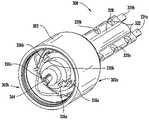
도 3은 본 발명의 예시적 실시예에 따라서 베이스, 제어 부품 단자, 전자 제어 부품, 제 1 및 제 2 가열 단자, 유동 디렉터, 저장조 기판, 분무기, 외부 보디, 마우쓰피스, 및 라벨을 구비하는 도 1의 카트리지의 분해 사시도이다.
도 4는 본 발명의 예시적 실시예에 따른, 도 3의 유동 디렉터와 제 1 및 제 2 가열 단자의 후방의 저면 사시도이다.
도 5는 본 발명의 예시적 실시예에 따른, 도 3의 유동 디렉터와 제 1 및 제 2 가열 단자의 전방의 대향 저면 사시도이다.
도 6은 본 발명의 예시적 실시예에 따른, 도 3의 베이스, 전자 제어 부품, 및 제어 부품 단자의 평면 사시도이다.
도 7은 본 발명의 예시적 실시예에 따른 도 3의 가열 단자를 추가로 구비하는 도 6의 조립체의 평면 사시도이다.
도 8은 본 발명의 예시적 실시예에 따른 도 3의 유동 디렉터를 추가로 구비하는 도 7의 조립체의 저면 사시도이다.
도 9는 본 발명의 예시적 실시예에 따른 도 3의 분무기를 추가로 구비하는 도 8의 조립체의 측면 사시도이다.
도 10은 본 발명의 예시적 실시예에 따른 도 3의 저장조 기판을 추가로 구비하는 도 9의 조립체의 도시도이다.
도 11은 베이스 및 유동 디렉터 상의 변형 가능한 리브가 외부 보디와 결합하는 본 발명의 실시예에 따른 11 - 11 라인을 따라서 취한 도 2의 카트리지의 부분 단면도이다.
도 12는 유동 디렉터가 베이스 및 외부 보디에 용접되는 본 발명의 실시예에 따른 11 - 11 라인을 따라서 취한 도 2의 카트리지의 부분 단면도이다.
도 13은 본 발명의 예시적 실시예에 따른, 외부 보디가 명료함을 위해 은폐되고 유동 디렉터가 리세스를 갖는, 13 - 13 라인을 따라서 취한 도 2의 카트리지의 단면도이다.
도 14는 본 발명의 예시적 실시예에 따른 14 - 14 라인을 따라서 취한 도 2의 카트리지의 단면도이다.
도 15는 마우쓰피스가 립을 구비하는, 본 발명의 예시적 실시예에 따른 15 - 15 라인을 따라서 취한 도 2의 카트리지의 부분 단면도이다.
도 16은 분무기가 유동 디렉터를 통해서 연장되는, 본 발명의 예시적 실시예에 따른 14 - 14 라인을 따라서 취한 도 2의 카트리지의 개략 단면도이다.
도 17은 베이스 및 유동 디렉터 상의 변형 가능한 리브가 외부 보디와 결합되고 플랩 밸브를 추가로 구비하는 본 발명의 실시예에 따른 11 - 11 라인을 따라서 취한 도 2의 카트리지의 부분 단면도이다.
도 18은 유동 디렉터가 베이스 및 외부 보디에 용접되고 크로스 밸브를 추가로 구비하는 본 발명의 실시예에 따른 11 - 11 라인을 따라서 취한 도 2의 카트리지의 부분 단면도이다.
도 19는 본 발명의 예시적 실시예에 따른 카트리지 조립 방법의 개략도이다.
도 20은 본 발명의 예시적 실시예에 따른 컨트롤러의 개략도이다.While the present invention has been described in general language, reference will now be made to the accompanying drawings, which are not necessarily drawn to scale.
1 is a side view of an aerosol delivery device in an assembled configuration, the aerosol delivery device having an overall structure that may be characterized as an electronic cigarette, comprising a control body and a cartridge according to an exemplary embodiment of the present invention;
FIG. 2 is a side view of the cartridge of the aerosol delivery device of FIG. 1 and a cross-sectional view of the control body, with the cartridge disengaged from the control body in accordance with an exemplary embodiment of the present invention;
3 is a diagram of a device having a base, control component terminals, electronic control component, first and second heating terminals, flow director, reservoir substrate, atomizer, outer body, mouthpiece, and label in accordance with an exemplary embodiment of the present invention; 1 is an exploded perspective view of the cartridge.
FIG. 4 is a rear, bottom perspective view of the flow director and first and second heating terminals of FIG. 3, in accordance with an exemplary embodiment of the present invention;
5 is a front, opposite, bottom perspective view of the flow director and first and second heating terminals of FIG. 3, in accordance with an exemplary embodiment of the present invention;
Fig. 6 is a top perspective view of the base, electronic control component, and control component terminal of Fig. 3, in accordance with an exemplary embodiment of the present invention;
7 is a top perspective view of the assembly of FIG. 6 further including the heating terminal of FIG. 3 in accordance with an exemplary embodiment of the present invention;
8 is a bottom perspective view of the assembly of FIG. 7 further including the flow director of FIG. 3 in accordance with an exemplary embodiment of the present invention;
9 is a side perspective view of the assembly of FIG. 8 further including the atomizer of FIG. 3 in accordance with an exemplary embodiment of the present invention;
10 is an illustration of the assembly of FIG. 9 further including the reservoir substrate of FIG. 3 in accordance with an exemplary embodiment of the present invention.
11 is a partial cross-sectional view of the cartridge of FIG. 2 taken along line 11 - 11 in accordance with an embodiment of the present invention in which deformable ribs on the base and flow director engage the outer body;
12 is a partial cross-sectional view of the cartridge of FIG. 2 taken along line 11-11 in accordance with an embodiment of the present invention in which a flow director is welded to the base and outer body;
13 is a cross-sectional view of the cartridge of FIG. 2 taken along line 13 - 13, with the flow director having recesses and the outer body concealed for clarity, in accordance with an exemplary embodiment of the present invention.
14 is a cross-sectional view of the cartridge of FIG. 2 taken along line 14 - 14 in accordance with an exemplary embodiment of the present invention.
15 is a partial cross-sectional view of the cartridge of FIG. 2 taken along line 15 - 15 in accordance with an exemplary embodiment of the present invention, wherein the mouthpiece has a lip;
16 is a schematic cross-sectional view of the cartridge of FIG. 2 taken along line 14 - 14 in accordance with an exemplary embodiment of the present invention, with the nebulizer extending through the flow director;
FIG. 17 is a partial cross-sectional view of the cartridge of FIG. 2 taken along line 11 - 11 in accordance with an embodiment of the present invention wherein the deformable ribs on the base and flow director engage the outer body and further include a flap valve;
FIG. 18 is a partial cross-sectional view of the cartridge of FIG. 2 taken along line 11 - 11 in accordance with an embodiment of the present invention wherein the flow director is welded to the base and outer body and further includes a cross valve;
19 is a schematic diagram of a cartridge assembly method according to an exemplary embodiment of the present invention.
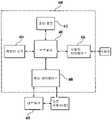
20 is a schematic diagram of a controller according to an exemplary embodiment of the present invention;
이제 이하에서는 본 발명을 그 예시적 실시예를 참조하여 보다 충실하게 설명할 것이다. 이들 예시적 실시예는 본 발명이 철저하고 완전해지고 발명의 범위가 통상의 기술자에게 충실히 전달되도록 설명된다. 실제로, 본 발명은 여러가지 다양한 형태로 구체화될 수 있고, 본 명세서에 기재된 실시예에 제한되는 것으로 간주되지 않아야 하며; 오히려 이들 실시예는 본 발명이 적용 가능한 법적 요구사항을 충족하도록 제공된다. 명세서 및 청구범위에 사용될 때, 단수 형태의 관사 및 정관사는 달리 명시되지 않는 한 복수의 변형을 포함한다.The present invention will now be more fully described with reference to exemplary embodiments thereof. These exemplary embodiments are described so that this invention will be thorough and complete, and will fully convey the scope of the invention to those skilled in the art. Indeed, the present invention may be embodied in many different forms and should not be construed as limited to the examples set forth herein; Rather, these embodiments are provided so that the present invention will satisfy applicable legal requirements. As used in the specification and claims, the singular and definite articles include plural variations unless otherwise specified.
본 발명에 따른 에어로졸 송달 장치는 재료를 (바람직하게는 재료를 상당한 정도로 연소시키지 않으면서) 가열하여 흡입 가능한 물질을 형성하기 위해 전기 에너지를 사용할 수 있으며; 이러한 물품은 "손잡이식" 장치로 간주되기에 충분히 콤팩트한 것이 가장 바람직하다. 에어로졸 송달 장치는 물품 또는 장치의 임의의 성분의 임의의 상당한 정도의 연소 없이 궐련, 여송연, 또는 파이프를 흡연하는 감각(예를 들면, 호흡 행위, 풍미나 향미의 형태, 관능 효과, 신체 느낌, 사용 행위, 가시 에어로졸에 의해 제공되는 것과 같은 시각적 단서 등)의 일부 또는 전부를 제공할 수 있다. 에어로졸 송달 장치는 담배의 연소 또는 열분해의 부산물에 기인하는 에어로졸의 의미로 연기를 발생시키지 않을 수도 있지만, 오히려 물품 또는 장치는 물품 또는 장치의 특정 성분의 휘발 또는 증발에 기인하는 증기(연기와 유사한 것으로 기재되는 것으로 간주될 수도 있는 가시 에어로졸인 것으로 간주될 수 있는 에어로졸 내의 증기를 포함)를 산출하는 것이 가장 바람직하다. 매우 바람직한 실시예에서, 에어로졸 송달 장치는 담배 및/또는 담배에서 유래되는 성분을 포함할 수 있다. 따라서, 에어로졸 송달 장치는 전자 담배와 같은 전자 흡연 물품으로서 특징지어질 수 있다.The aerosol delivery device according to the present invention can use electrical energy to heat a material (preferably without burning the material to a significant extent) to form an inhalable substance; It is most desirable that such articles are compact enough to be considered "handled" devices. Aerosol delivery devices provide for the sensation of smoking a cigarette, cigar, or pipe without any significant degree of combustion of any component of the article or device (e.g., the act of breathing, form of flavor or flavor, sensory effect, body feeling, use behavior, visual cues such as those provided by visible aerosols, etc.). An aerosol delivery device may not emit smoke in the sense of an aerosol resulting from the by-product of the combustion or pyrolysis of tobacco, but rather the article or device produces vapors (similar to smoke) resulting from volatilization or evaporation of certain components of the article or device. It is most desirable to yield vapors in the aerosol that may be considered to be visible aerosols that may be considered as described). In a highly preferred embodiment, the aerosol delivery device may comprise tobacco and/or tobacco-derived components. Accordingly, the aerosol delivery device may be characterized as an electronic smoking article, such as an electronic cigarette.
본 발명의 에어로졸 송달 시스템은 또한 증기-생성 물품 또는 약물 송달 물품인 것을 특징으로 할 수 있다. 따라서, 이러한 물품 또는 장치는 하나 이상의 물질(예를 들면, 향미료 및/또는 의약품 활성 성분)을 흡입 가능한 형태 또는 상태로 제공하도록 구성될 수 있다. 예를 들어, 흡입 가능한 물질은 실질적으로 증기(즉, 그 임계점 미만의 온도에서 기체상인 물질)의 형태로 제공될 수 있다. 대안적으로, 흡입 가능한 물질은 에어로졸(즉, 기체 내의 미세한 고체 입자 또는 액적의 현탁액)의 형태일 수 있다. 간명함을 위해, 본 명세서에 사용되는 용어 "에어로졸"은 가시적인지 여부에 관계없이 또한 연기와 유사한 것으로 간주될 수 있는 형태인지 여부에 관계없이 사람이 흡입하기에 적합한 형태 또는 타입의 증기, 기체, 및 에어로졸을 포함하도록 의미된다.The aerosol delivery system of the present invention may also be characterized as being a vapor-generating article or a drug delivery article. Accordingly, such articles or devices may be configured to provide one or more substances (eg, flavorings and/or pharmaceutical active ingredients) in an inhalable form or condition. For example, the inhalable substance may be provided substantially in the form of a vapor (ie, a substance that is in the gaseous phase at a temperature below its critical point). Alternatively, the inhalable substance may be in the form of an aerosol (ie, a suspension of fine solid particles or droplets in a gas). For the sake of brevity, the term "aerosol" as used herein refers to vapors, gases, and vapors of a form or type suitable for inhalation by a person, whether visible or not and in a form that can be considered similar to smoke, and is meant to include aerosols.
사용 시에, 본 발명의 에어로졸 송달 장치는 전통적인 형태의 흡연 물품(예를 들면, 담배를 불붙이고 흡입함으로써 채용되는 궐련, 여송연 또는 파이프)의 사용 시에 개인이 취하는 여러가지 신체 행동을 받을 수 있다. 예를 들어, 본 발명의 에어로졸 송달 장치의 사용자는 그 물품을 전통적인 형태의 흡연 물품과 매우 흡사하게 쥐고, 그 물품에 의해 생성되는 에어로졸의 흡입을 위해 그 물품의 일 단부를 물고, 선택된 시간 간격으로 모금(puff)을 피우는 등을 행할 수 있다.In use, the aerosol delivery device of the present invention may be subjected to various physical actions taken by an individual upon use of a smoking article of a traditional type (eg, a cigarette, cigar or pipe employed by lighting and inhaling a cigarette). For example, a user of an aerosol delivery device of the present invention holds the article very much like a traditional form of smoking article, bites one end of the article for inhalation of the aerosol produced by the article, and at selected time intervals You can smoke a puff, and the like.
본 발명의 흡연 물품은 일반적으로 외부 셸 또는 보디 내에 제공되는 다수의 부품을 구비한다. 외부 셸 또는 보디의 전체 설계는 변경될 수 있으며, 흡연 물품의 전체 크기와 형상을 규정할 수 있는 외부 보디의 포맷 또는 구조는 변경될 수 있다. 통상적으로, 궐련 또는 여송연의 형상과 유사한 세장형 보디가 단일의 일체형 셸로 형성될 수 있거나; 또는 상기 세장형 보디는 두 개 이상의 분리 가능한 피스로 형성될 수 있다. 예를 들어, 흡연 물품은 실질적으로 튜브형 형상일 수 있는 세장형 셸 또는 보디를 포함할 수 있으며, 따라서 종래의 궐련 또는 여송연의 형상을 닮을 수 있다. 일 실시예에서는, 흡연 물품의 부품의 전부가 하나의 외부 보디 또는 셸 내에 수용된다. 대안적으로, 흡연 물품은 결합되고 분리될 수 있는 두 개 이상의 셸을 포함할 수 있다. 예를 들어, 흡연 물품의 일 단부에는 하나 이상의 재사용 가능한 부품들(예를 들면, 충전식 배터리 및 상기 물품의 작동을 제어하기 위한 각종 전자기기)을 수용하는 셸을 포함하는 제어 보디가 구비될 수 있고, 타 단부에는 일회용 부분(예를 들면, 일회용 향미료-수용 카트리지)을 수용하는 셸이 착탈식으로 부착될 수 있다. 단일 셸 타입의 유닛 내의 또는 다중-피스 분리형 셸 타입의 유닛 내의 부품들의 보다 구체적인 포맷, 구성 및 배치는 본 명세서에 제공되는 추가 설명을 감안하면 자명할 것이다. 또한, 본 발명의 배경기술 항목에서 열거한 대표 제품들과 같은 시판되는 전자 흡연 물품을 고려할 때 다양한 흡연 물품 설계 및 부품 구조가 이해될 수 있다.Smoking articles of the present invention generally have a number of components provided within an outer shell or body. The overall design of the outer shell or body may vary, and the format or structure of the outer body may vary, which may define the overall size and shape of the smoking article. Typically, an elongate body resembling the shape of a cigarette or cigar may be formed from a single unitary shell; Alternatively, the elongate body may be formed of two or more separable pieces. For example, a smoking article may include an elongate shell or body, which may be of a substantially tubular shape, and thus may resemble the shape of a conventional cigarette or cigar. In one embodiment, all of the parts of the smoking article are contained within one outer body or shell. Alternatively, the smoking article may include two or more shells that may be joined and separated. For example, one end of a smoking article may be provided with a control body including a shell containing one or more reusable parts (eg, a rechargeable battery and various electronics for controlling the operation of the article) and , at the other end may be removably attached to a shell containing a disposable portion (eg, a disposable flavor-receiving cartridge). More specific formats, configurations, and arrangements of parts within a single shell type unit or within a multi-piece separate shell type unit will become apparent in light of the further description provided herein. In addition, various smoking article designs and component structures can be understood when considering commercially available electronic smoking articles, such as the representative products listed in the Background section of the present invention.
본 발명의 에어로졸 송달 장치는 전원(즉, 전기 전원), 하나 이상의 제어 부품(예를 들면, 전원으로부터 에어로졸 송달 장치의 다른 부품으로의 전류 유동을 제어하는 등에 의해 발열을 위한 전력을 조작, 제어, 규제 및 중지하기 위한 수단), 히터 또는 발열 부품(예를 들면, "분무기"의 부분으로 통칭되는 전기 저항 가열 요소 또는 부품), 에어로졸 전구체 조성물(예를 들면, "스모크 주스", "e-액체" 및 "e-주스"로 통칭되는 성분과 같은, 통상 충분한 열이 가해지면 에어로졸을 발생시킬 수 있는 액체), 및 에어로졸 흡입을 위해 에어로졸 송달 장치를 물 수 있게 하기 위한 마우쓰단부 영역 또는 선단(예를 들어, 물면 발생된 에어로졸이 물품으로부터 인출될 수 있도록 물품을 통해서 형성되는 공기 유동 경로)의 어떤 조합을 포함하는 것이 가장 바람직하다. 본 발명에 따라 사용될 수 있는 에어로졸 전구체 재료를 위한 예시적 제제는 그 전체 내용이 본 명세서에 참조로 원용되는 Zheng 등의 미국 특허 공개 제2013/0008457호 및 Chong 등의 제2013/0213417호에 기재되어 있다.The aerosol delivery device of the present invention may manipulate, control, power for heat generation by a power source (i.e., an electrical power source), one or more control components (e.g., controlling the flow of current from the power source to other components of the aerosol delivery device, etc.); means for regulating and stopping), heaters or heating components (eg, electrically resistive heating elements or components collectively referred to as part of a “nebulizer”), aerosol precursor compositions (eg, “smoke juice”, “e-liquid”) "and liquids capable of generating an aerosol when sufficiently heated, such as ingredients collectively referred to as " and "e-juice"), and a mouth area or tip ( For example, it is most desirable to include some combination of air flow paths formed through the article such that the bitten generated aerosol can be withdrawn from the article. Exemplary formulations for aerosol precursor materials that may be used in accordance with the present invention are described in US Patent Publication Nos. 2013/0008457 to Zheng et al. and 2013/0213417 to Chong et al., which are incorporated herein by reference in their entirety. have.
에어로졸 송달 장치 내의 부품들의 정렬은 변경될 수 있다. 특정 실시예에서, 에어로졸 전구체 조성물은 사용자에게로의 에어로졸 송달을 최대화하기 위해 사용자의 입에 근접하여 배치되도록 구성될 수 있는 에어로졸 송달 장치의 단부 근처에 위치할 수 있다. 그러나, 다른 구성이 배제되지는 않는다. 일반적으로, 가열 요소는, 가열 요소로부터의 열이 에어로졸 전구체(뿐 아니라 마찬가지로 사용자에게 송달되기 위해 제공될 수 있는 하나 이상의 향미료, 약물 등)를 휘발시킬 수 있고 사용자에게 송달하기 위한 에어로졸을 형성할 수 있도록 에어로졸 전구체 조성물에 충분히 근접하여 배치될 수 있다. 가열 요소가 에어로졸 전구체 조성물을 가열하면, 에어로졸이 소비자가 흡입하기에 적합한 물리적 형태로 형성, 방출 또는 발생된다. 상기 용어들은 용어 "방출", "방출하는", "방출한다" 또는 "방출되는"이 "형성 또는 발생", "형성하는 또는 발생하는", "형성한다 또는 발생한다" 및 "형성된다 또는 발생된다"를 포함하도록 상호 교환될 수 있음을 의미함을 알아야 한다. 구체적으로, 흡입가능한 물질은 증기 또는 에어로졸 또는 그 혼합물의 형태로 방출된다.The alignment of the components within the aerosol delivery device may be altered. In certain embodiments, the aerosol precursor composition may be positioned near the end of an aerosol delivery device that may be configured to be disposed proximate to the user's mouth to maximize aerosol delivery to the user. However, other configurations are not excluded. In general, a heating element is capable of volatilizing an aerosol precursor (as well as one or more flavoring agents, drugs, etc. that may likewise be provided for delivery to a user) and forming an aerosol for delivery to a user, wherein heat from the heating element is capable of volatilizing It can be disposed in sufficient proximity to the aerosol precursor composition so as to When the heating element heats the aerosol precursor composition, the aerosol is formed, released, or generated in a physical form suitable for inhalation by a consumer. The terms "release", "release", "release" or "released" refer to "forms or occurs", "forms or occurs", "forms or occurs" and "forms or occurs" be used interchangeably to include "become". Specifically, inhalable substances are released in the form of vapors or aerosols or mixtures thereof.
전술했듯이, 에어로졸 송달 장치는 히터의 급전, 제어 시스템의 급전, 인디케이터의 급전 등과 같은 다양한 기능을 물품에 제공하기에 충분한 전류 유동을 공급하기 위해 배터리 또는 기타 전기 전원(예를 들면, 커패시터)을 포함할 수 있다. 전원은 다양한 실시예를 취할 수 있다. 바람직하게, 전원은 소정 기간 동안의 사용을 통해서 에어로졸 형성을 제공하고 에어로졸 송달 장치에 급전하기 위해 가열 부재를 급속 가열하기에 충분한 전력을 송달할 수 있다. 전원은 에어로졸 송달 장치가 쉽게 취급될 수 있도록 에어로졸 송달 장치 내에 꼭 끼워지도록 크기형성되는 것이 바람직하다. 또한 전원은 바람직한 흡연 경험을 손상시키지 않도록 충분히 가벼운 것이 바람직하다.As noted above, an aerosol delivery device includes a battery or other electrical power source (eg, a capacitor) to provide a current flow sufficient to provide the article with various functions, such as powering a heater, powering a control system, powering an indicator, etc. can do. The power source may take various embodiments. Preferably, the power source is capable of delivering sufficient power to rapidly heat the heating element to provide aerosol formation and power the aerosol delivery device through use for a period of time. The power source is preferably sized to fit snugly within the aerosol delivery device so that the aerosol delivery device can be easily handled. It is also desirable that the power source be sufficiently light so as not to impair the desirable smoking experience.
본 발명의 에어로졸 송달 장치 내의 부품들의 보다 구체적인 포맷, 구성 및 배치는 이후 제공되는 추가 설명을 감안하면 자명할 것이다. 또한, 본 발명의 배경기술 항목에서 열거한 대표 제품들과 같은 시판되는 전자 에어로졸 송달 장치를 고려할 때 다양한 에어로졸 송달 장치 부품의 선택이 이해될 수 있다. 추가로, 본 발명의 배경기술 항목에서 열거한 대표 제품들과 같은 시판되는 전자 에어로졸 송달 장치를 고려할 때 에어로졸 송달 장치 내의 부품의 배치도 이해될 수 있다.More specific formats, configurations, and placement of the components within the aerosol delivery device of the present invention will be apparent in light of the additional description provided hereinafter. In addition, the selection of various aerosol delivery device components can be appreciated when considering commercially available electronic aerosol delivery devices such as the representative products listed in the Background section of the present invention. Additionally, the arrangement of components within the aerosol delivery device may be understood when considering commercially available electronic aerosol delivery devices such as the representative products listed in the background section of the present invention.
본 발명에 따른 에어로졸 송달 장치(100)의 한 가지 예시적 실시예가 도 1에 도시되어 있다. 도시하듯이, 에어로졸 송달 장치(100)는 제어 보디(200)와 카트리지(300)를 구비할 수 있다. 이와 관련하여, 도 1은 조립된 구조에 있는 제어 보디(200)와 카트리지(300)를 각각 도시하며, 제어 보디와 카트리지는 상호 결합된다. 다양한 기구가 제어 보디(200)를 카트리지(300)에 연결하여 나사 결합, 압입 결합, 억지 끼워맞춤, 마그네틱 결합 등을 초래할 수 있다.One exemplary embodiment of an
제어 보디(200)와 카트리지(300)의 부품들은 다양한 재료로 형성될 수 있다. 예를 들어, 에어로졸 송달 장치의 부품을 형성하기 위해 플라스틱[예를 들면, 폴리카보네이트 또는 아크릴로니트릴 부타디엔 스티렌(ABS)], 금속(예를 들면, 스테인레스 스틸 또는 알루미늄), 판지(paperboard), 마분지(cardboard), 세라믹, 파이버글래스, 유리(예를 들면, 탄성 글래스), 또는 흑연 복합재가 사용될 수 있다. 에어로졸 송달 장치에 사용될 수 있는 다양한 다른 재료는 그 특정한 구체적인 성분을 특히 참조하여 이하에서 논의된다.The
에어로졸 송달 장치(100)는 카트리지 보디(200)와 제어 보디(300)가 상호 결합될 때 일부 실시예에서 실질적으로 봉-형상이거나 실질적으로 튜브 형상이거나 실질적으로 원통 형상일 수 있다. 이와 관련하여, 일부 실시예에서는 궐련 또는 여송연과 같은 흡연 물품과 유사한 크기, 형상 및/또는 구성을 갖는 에어로졸 송달 장치(100)를 제공하는 것이 바람직할 수 있다. 따라서, 일부 실시예에서 제어 보디(200)와 카트리지(300)는 대체로 원통형일 수 있으며 에어로졸 송달 장치(100)는 그 사이의 결합의 결과로서 세장형 원통형 구조를 가질 수 있다. 따라서, 에어로졸 송달 장치(100)의 통상적인 크기, 형상 및/또는 전체적인 외관은 시판중인 전자 담배에 비견될 수 있다.The
일부 실시예에서, 제어 보디(200)와 카트리지(300)는 거의 동일한 종방향 길이를 가질 수 있다. 그러나, 다른 실시예에서 제어 보디(200)와 카트리지(300)는 상이한 종방향 길이를 가질 수 있다. 예를 들어, 카트리지(300)의 종방향 길이 대 제어 보디(200)의 종방향 길이의 비율은 약 2:1 내지 약 1:2, 약 3:5 내지 약 5:3, 또는 약 4:5 내지 약 5:4일 수 있다. 이와 관련하여, 일부 실시예에서 카트리지(300)의 치수는 필터 요소의 치수와 유사할 수 있으며 제어 보디(200)의 치수는 전통적인 궐련의 담배 봉의 치수와 유사할 수 있다. 이 구조는 제어 보디(200) 내에 전기 전원을 위한 적절한 공간을 제공할 수 있으며, 전기 전원은 전술했듯이 또한 후술하듯이 그 안에 구비될 수 있다.In some embodiments,
일 실시예에서 제어 보디(200)와 카트리지(300)는 도 1에 도시된 구조에서 상호 영구적으로 결합될 수 있다. 쓰고 버려질 수 있도록 구성될 수 있거나 및/또는 영구적으로 결합하도록 구성되는 제 1 및 제 2 외부 보디를 구비할 수 있는 에어로졸 송달 장치의 예는 그 전체가 본 명세서에 참조로 원용되는 Bless 등의 2014년 2월 3일자 미국 특허 출원 제14/170,838호에 개시되어 있다. 그러나, 다른 실시예에서 제어 보디(200)와 카트리지(300)는 분리될 수 있도록 구성될 수 있다. 이와 관련하여, 도 2는 결합 해제된 구조에 있는 제어 보디(200)와 카트리지(300)를 도시하며, 여기에는 카트리지의 측면도 및 제어 보디의 단면도가 제공된다.In one embodiment, the
특정 실시예에서, 제어 보디(200)와 카트리지(300)의 하나 또는 양자는 일회용인 것으로 또는 재사용 가능한 것으로 지칭될 수 있다. 예를 들어, 제어 보디(200)는 교체형 배터리 또는 재충전식 배터리를 가질 수 있으며 따라서 통상의 전기 콘센트에 대한 연결, 자동차 충전기(즉, 시가 잭)에 대한 연결, 및 USB 케이블 등을 통한 컴퓨터 연결을 포함하는 재충전 기술의 임의의 형태와 조합될 수 있다. 또한, 일부 실시예에서 카트리지(300)는 그 전체가 본 명세서에 참조로 원용되는 Chang 등의 미국 특허 공개 제2014/0060555호에 개시되어 있는 일회용 카트리지를 포함할 수 있다.In certain embodiments, one or both of
도 2에 도시하듯이, 제어 보디(200)는 다수의 부품을 포함할 수 있다. 예를 들어, 제어 보디(200)는 커플러(202), 외부 보디(204), 유동 센서(210), 제어 부품(212), 전기 전원(216)(예를 들면, 재충전될 수 있는 배터리), 인디케이터(218)(예를 들면, LED 인디케이터) 및 단부 캡(222)을 구비할 수 있다. 제어 보디에 구비될 수 있는 다양한 요소는 본 명세서에 그 전체가 참조로 원용되는 Worm 등의 2014년 2월 28일자 미국 특허 출원 제14/193,961호에 기재되어 있다.As shown in FIG. 2 , the
본 발명에 따른 에어로졸 송달 장치의 다양한 부품은 배경기술에 기재되고 시판 중인 부품들로부터 선택될 수 있다. 본 발명에 따라 사용될 수 있는 배터리의 예는 그 전체가 본 명세서에 원용되는 Peckerar 등의 미국 특허 공개 제2010/0028766호에 기재되어 있다.The various components of the aerosol delivery device according to the invention can be selected from those described in the background and commercially available. Examples of batteries that can be used in accordance with the present invention are described in US Patent Publication No. 2010/0028766 to Peckerar et al., which is incorporated herein in its entirety.
에어로졸 발생 피스는 에어로졸 발생이 요구될 때(예를 들면 사용 중에 빨아들일 때) 발열 요소로의 전력 공급을 제어하기 위한 센서 또는 검출기를 포함하는 것이 가장 바람직하다. 따라서, 예를 들어, 사용 중에 에어로졸 발생 피스가 빨리지 않을 때 발열 요소로의 전력 공급을 턴오프하고 흡입 중에 발열 요소에 의한 발열을 작동 또는 촉발하기 위해 전력 공급을 턴온하기 위한 방식 또는 방법이 제공된다. 감지 또는 검출 기구, 그 구조 및 구성, 그 부품, 및 그 전반적인 작동 방법의 추가적인 대표적 형태가 Sprinkel 2세의 미국 특허 제5,261,424호; McCafferty 등의 미국 특허 제5,372,148호; 및 Flick의 PCT WO 2010/003480호에 기재되어 있으며, 이들 문헌은 본 명세서에 참조로 원용된다.It is most preferred that the aerosol-generating piece comprises a sensor or detector for controlling the supply of power to the heating element when aerosol generation is desired (eg when sucked in during use). Thus, for example, a manner or method is provided for turning off the power supply to the heating element when the aerosol-generating piece is not fastening during use and for turning on the power supply to actuate or trigger heat generation by the heating element during inhalation. do. Additional representative forms of sensing or detection devices, their structure and construction, their components, and their overall method of operation are described in US Pat. Nos. 5,261,424 to Sprinkel II; US Pat. No. 5,372,148 to McCafferty et al.; and PCT WO 2010/003480 to Flick, which are incorporated herein by reference.
에어로졸 발생 피스는 흡입 중에 발열 요소로의 전력 양을 제어하기 위한 제어 기구를 포함하는 것이 가장 바람직하다. 전자 부품, 그 구조와 구성, 그 특징부, 및 그 전반적인 작동 방법의 대표적인 형태는 Gerth 등의 미국 특허 제4,735,217호; Brooks 등의 미국 특허 제4,947,874호; McCafferty 등의 미국 특허 제5,372,148호; Fleischhauer 등의 미국 특허 제6,040,560호; Nguyen 등의 미국 특허 제7,040,314호; Pan의 미국 특허 제8,205,622호; Fernando 등의 미국 특허 공개 제2009/0230117호; Collett 등의 미국 특허 공개 제2014/0060554호; Ampolini 등의 2013년 3월 15일자 미국 특허 출원 제13/837,542호; 및 Henry 등의 2014년 3월 13일자 미국 특허 출원 제14/209,191호에 기재되어 있으며, 이들 문헌은 본 명세서에 참조로 원용된다.Most preferably, the aerosol-generating piece comprises a control mechanism for controlling the amount of power to the heating element during inhalation. Representative forms of electronic components, their structures and configurations, their features, and their overall operating methods are described in US Pat. Nos. 4,735,217 to Gerth et al; US Pat. No. 4,947,874 to Brooks et al.; US Pat. No. 5,372,148 to McCafferty et al.; US Pat. No. 6,040,560 to Fleischhauer et al.; US Pat. No. 7,040,314 to Nguyen et al.; U.S. Pat. No. 8,205,622 to Pan; US Patent Publication No. 2009/0230117 to Fernando et al.; US Patent Publication No. 2014/0060554 to Collett et al.; U.S. Patent Application Serial No. 13/837,542, filed Mar. 15, 2013 to Ampolini et al.; and Henry et al., U.S. Patent Application No. 14/209,191, filed March 13, 2014, which is incorporated herein by reference.
에어로졸 전구체를 지지하기 위한 기판, 저장조 또는 기타 부품의 대표적인 형태는 Newton의 미국 특허 제8,528,569호; Chapman 등의 2013년 3월 15일자 미국 특허 출원 제13/802,950호; Davis 등의 2013년 8월 28일자 미국 특허 출원 제14/011,192호; 및 Bless 등의 2014년 2월 3일자 미국 특허 출원 제14/170,838호에 기재되어 있으며, 이들 문헌은 본 명세서에 참조로 원용된다. 또한, 다양한 심지이동 재료, 및 특정 형태의 전자 담배 내에서의 이들 심지이동 재료의 구성 및 작동은 본 명세서에 참조로 원용되는 Sears 등의 2013년 1월 30일자 미국 특허 출원 제13/754,324호에 제시되어 있다. 상기 문헌에 개시된 다양한 재료는 다양한 실시예에서 본 장치에 통합될 수 있으며, 상기 개시내용의 전부는 그 전체가 본 명세서에 참조로 원용된다.Representative types of substrates, reservoirs, or other components for supporting aerosol precursors are described in Newton's US Patent Nos. 8,528,569; US Patent Application Serial No. 13/802,950, filed Mar. 15, 2013 to Chapman et al.; US Patent Application Serial No. 14/011,192, filed Aug. 28, 2013 to Davis et al.; and US Patent Application Serial No. 14/170,838, filed Feb. 3, 2014 to Bless et al., which are incorporated herein by reference. Also, various wicking materials, and the construction and operation of these wicking materials in certain types of e-cigarettes, are described in U.S. Patent Application Serial No. 13/754,324, filed Jan. 30, 2013 to Sears et al., which is incorporated herein by reference. is presented. The various materials disclosed in this document may be incorporated into the present apparatus in various embodiments, the entire disclosure of which is incorporated herein by reference in its entirety.
도 3은 분해된 구조에 있는 카트리지(300)를 도시한다. 도시하듯이, 카트리지(300)는 본 발명의 예시적 실시예에 따르면 베이스(302), 제어 부품 단자(304), 전자 제어 부품(306), 유동 디렉터(308), 분무기(310), 저장조 기판(312), 외부 보디(314), 마우쓰피스(316), 라벨(318), 제 1 및 제 2 가열 단자(320a, 320b)를 포함할 수 있다. 분무기(310)는 액체 운송 요소(322) 및 가열 요소(324)를 포함할 수 있다. 카트리지는 예를 들어 Depiano 등의 2013년 3월 15일자 미국 특허 출원 제13/841,233호에 개시되어 있듯이 베이스와 마우쓰피스를 보호하고 사용 전에 그 안에 오염물질이 진입하는 것을 방지하기 위해 베이스와 결합되는 베이스 시핑 플러그 및/또는 마우쓰피스와 결합되는 마우쓰피스 시핑 플러그를 추가로 구비할 수 있다. 이하의 설명은 상기 부품들 및 그 조립 방법의 예시적 구조를 제공한다. 그러나, 카트리지(300)는 다양한 방식으로 조립될 수 있으며 다른 실시예에서 추가 부품이나 보다 적은 수의 부품을 구비할 수도 있음을 알아야 한다. 예를 들어, 카트리지(300)는 본 명세서에서 저장조 기판을 구비하는 것으로 대체로 기재되어 있지만, 다른 실시예에서 카트리지는 저장조 기판을 사용하지 않고 (예를 들면, 에어로졸 전구체 조성물을 보관하는 컨테이너나 용기 또는 그 안의 직접 저장장치의 사용을 통해서) 그 안에 에어로졸 전구체 조성물을 보유할 수 있다. 일부 실시예에서, 에어로졸 전구체 조성물은 다공질(예를 들면, 섬유질) 재료를 그 안에 구비할 수도 있는 컨테이너 또는 용기 내에 제공될 수 있다.3 shows the
도 4는 유동 디렉터(308)와 제 1 및 제 2 가열 단자(320a, 320b)의 후방의 저면 사시도이며, 도 5는 유동 디렉터와 가열 단자의 전방의 평면 사시도이다. 이후 논의하듯이, 유동 디렉터(308)는 제어 보디(200)로부터 수용될 수 있는 공기 유동을 분무기(310)(도 9와 관련하여 추가로 설명됨)의 가열 요소(324)로 인도하도록 구성될 수 있다. 추가로, 제 1 가열 단자(320a) 및 제 2 가열 단자(320b)(예를 들면, 양극 단자 및 접지 단자)는 카트리지(300)가 연결될 때 가열 요소(324)의 양 단부와 결합하고 제어 보디(200)와 전기적 연결을 형성하도록 구성된다.4 is a bottom perspective view of the rear of the
도 4 및 도 5에 도시하듯이, 가열 단자(320a, 320b)의 하나 또는 양자는 유동 디렉터(308)에 결합될 수 있다. 도시된 실시예에서 제 1 및 제 2 가열 단자(320a, 320b)는 유동 디렉터를 통해서 연장된다. 예를 들어, 제 1 및 제 2 가열 단자(320a, 320b)의 하나 또는 양자는 유동 디렉터(308) 내에 성형될 수 있다. 추가 예로서, 가열 단자(320a, 320b)는 유동 디렉터(308) 내에 삽입 성형될 수 있다. 이와 관련하여, 일부 실시예에서 유동 디렉터(308)는 성형 공정을 통해서 소정 구조로 형상화될 수 있다.4 and 5 , one or both of the
가열 단자(320a, 320b)를 유동 디렉터(308) 내에 성형하는 것은 특정한 이점을 제공할 수 있다. 이와 관련하여, 가열 단자(320a, 320b)를 유동 디렉터(308) 내에 성형하는 것은 가열 단자(320a, 320b)를 서로에 대해서 및 유동 디렉터에 대해서 정확하고 확실하게 배치하는 것을 가능하게 할 수 있다. 따라서, 예를 들어, 가열 요소 단자(320a, 320b) 사이의 정확한 분리 간격은 성형 공정 중에 설정될 수 있으며 이 분리 간격은 유동 디렉터(308)에 의해 형성되는 결과적 구조물에 의해 성형 공정 이후 유지될 수 있다. 또한, 가열 단자(320a, 320b)를 유동 디렉터(308)와 확실한 결합 상태로 제공하는 것은 카트리지의 제조 중에 보다 쉽게 파지 및 조작될 수 있는 비교적 큰 구조물을 제공함으로써 카트리지(300)의 제조를 더 촉진할 수 있다. 이와 관련하여, 본 발명의 카트리지(300)는 예를 들어 그 전체가 본 명세서에 참조로 원용되는 Ampolini 등의 2014년 3월 27일자 미국 특허 출원 제14/227, 159호에 개시된 자동 제조 기술을 사용하여 형성될 수 있다.Molding the
또한, 가열 단자(320a, 320b)를 유동 디렉터(308) 내에 성형하는 것은 가열 단자와 유동 디렉터 사이에 시일을 제공할 수 있다. 따라서, 가열 단자(320a, 320b)와 유동 디렉터(308) 사이의 유체 누설이 실질적으로 회피될 수 있다. 따라서, 예를 들어, 그렇지 않을 경우 카트리지의 충전 중에 발생할 수 있는 가열 단자(320a, 320b)를 따르는 에어로졸 전구체 조성물의 누설이 실질적으로 방지될 수 있다. 그러나, 알 수 있듯이, 가열 단자(320a, 320b)는 가열 단자가 유동 디렉터 내에 성형되지 않는 실시예에서 다른 방식으로 유동 디렉터(308)에 밀봉될 수 있다. 예를 들어, 가열 단자가 유동 디렉터를 통해서 연장되지만 그 안에 성형되지 않는 실시예에서는 가열 단자(320a, 320b)와 유동 디렉터(308) 사이에 밀봉재가 적용될 수 있다.Also, molding the
도시된 실시예에서 유동 디렉터(308)는 베이스 부분(326) 및 그로부터 연장되는 종방향 연장부(328)를 구비한다. 관통 구멍(330)이 유동 디렉터(308)의 종방향 길이를 따라서 베이스 부분(326) 및 종방향 연장부(328)를 통해서 연장될 수 있다. 이와 관련하여, 종방향 연장부(328)는 관통 구멍(330)을 둘러싸는 튜브를 가질 수 있다. 관통 구멍(330)은 제어 보디(200) 또는 커플러(202)로부터 베이스(302)를 통해서 수용될 수 있는 공기 유동을 베이스 부분(326) 및 종방향 연장부(328)를 통해서 분무기(310)의 가열 요소(324)로 인도하도록 구성될 수 있다. 이와 관련하여, 일부 실시예에서 제어 보디(200)(예를 들면 도 3 참조)의 커플러(202)는 예를 들어 그 전체가 본 명세서에 참조로 원용되는 2013년 3월 15일자 미국 특허 출원 제13/840,264호 및 Worm 등의 2014년 2월 28일자 미국 출원 제14/193,961호에 기재되어 있듯이 주위 공기가 이를 통해서 진입되어 카트리지의 베이스(302)로 이동하는 입구를 가질 수 있다. 그러나, 공기는 다른 실시예에서 각종 상이한 방식으로 카트리지에 진입할 수 있다.In the illustrated embodiment the
도시하듯이, 일부 실시예에서 가열 요소는 베이스 부분(326) 및 종방향 연장부(328)를 통해서 연장될 수 있다. 종방향 연장부(328)에는 절취부(332)가 형성될 수 있으며, 이 절취부에서 가열 단자(320a, 320b)가 노출될 수 있다. 절취부(332)는 유동 디렉터(308)가 재료를 덜 사용하여 형성될 수 있게 하거나 및/또는 전술했듯이 유동 디렉터 내에 가열 단자를 정확히 배치할 수 있도록 성형 공정 중에 가열 단자(320a, 320b)의 파지를 가능하게 할 수 있다.As shown, in some embodiments the heating element may extend through the
가열 단자(320a, 320b)는 그 양 단부에서 유동 디렉터(308)로부터 연장될 수 있다. 이와 관련하여, 제 1 가열 단자(320a)는 제 1 탭(334a)을 형성하기 위해 종방향 연장부(328)로부터 연장될 수 있으며 제 2 가열 단자(320b)는 제 2 탭(334b)을 형성하기 위해 종방향 연장부로부터 연장될 수 있다. 따라서, 가열 요소(324)(예를 들면 도 3 참조)는 전류가 이를 통해서 인도될 수 있도록 가열 단자(320a, 320b)에 결합(예를 들면 용접)될 수 있다.
유동 디렉터(308)의 양 단부에서, 제 1 가열 단자(320a)는 제 1 단부(336a)를 형성하기 위해 베이스 부분(326)으로부터 연장될 수 있으며 제 2 가열 단자(320b)는 제 2 단부(336b)를 형성하기 위해 베이스 부분(326)으로부터 연장될 수 있다. 가열 단자(320a, 320b)의 단부(336a, 336b)는 제어 보디(200)(예를 들면 도 2 참조)의 커플러(202) 내의 전기 접점과 결합하도록 구성될 수 있다. 일부 실시예에서 커플러(202) 내의 전기 접점은 그 전체가 본 명세서에 참조로 원용되는 DePiano 등의 미국 특허 출원 제13/841,233호에 기재되어 있듯이 커플러 내의 상이한 깊이에 배치되는 가변 반경의 원형 금속 밴드를 포함할 수 있다.At both ends of the
도 6은 베이스(302)의 확대 사시도이다. 도시하듯이, 베이스(302)는 전자 제어 부품(306)을 그 안에 수용하도록 구성된 리세스(338)를 가질 수 있다. 또한, 제어 부품 단자(304)는 베이스(302)와 결합될 수 있다. 도시하듯이, 제어 부품 단자(304)는 하나 이상의 날개(340)를 구비할 수 있다. 제어 부품 단자(304)를 베이스에 확실하게 유지하고 그 이동을 실질적으로 방지하기 위해 날개(340)는 베이스(302)에 형성된 선반(342) 및/또는 그것에 수직하게 연장되는 벽과 결합하도록 구성될 수 있다.6 is an enlarged perspective view of the
제어 부품 단자(304)의 제 1 단부(344)는 전자 제어 부품(306)과 결합하도록 구성될 수 있다. 제어 부품 단자(304)는 전자 제어 부품(306) 상의 접점(예를 들면 도 11 참조)과 결합하도록 구성된 역 절곡부(reverse bend)(346)를 가질 수 있다. 이와 관련하여, 제어 부품 단자(304)의 제 1 단부(344)는 베이스(302)에 대한 제어 부품 단자의 결합 이후에 그 사이의 확실한 연결을 제공하기 위해 전자 제어 부품(306)이 삽입될 수 있도록 리세스(338) 내로 하향 연장될 수 있다. 예를 들어, 역 절곡부(346)는 제어 부품 단자(304)가 그 제 1 단부(344)를 가압하여 전자 제어 부품(306)과 접촉시키는 스프링으로 작용하게 만들 수 있다. 그러나, 다른 실시예에서 전자 제어 부품(306)은 제어 부품 단자(304) 이전에 베이스(302) 내에 삽입될 수 있다.A
도 7은 가열 단자(320a, 320b)의 삽입 이후의 베이스(302)의 평면 사시도이며, 유동 디렉터(308)는 명료함을 위해 도시되지 않았다. 도시하듯이, 베이스(302)는 그 위에서 전자 제어 부품(306)을 지지하도록 구성된 선반(345)을 추가로 구비할 수 있다. 이와 관련하여, 유동 디렉터(308)는 유동 디렉터가 베이스(302)에 결합될 때 전자 제어 부품(306)과 결합하도록 구성된 하나 이상의 변형 가능한 리브(347)(도 4 참조)를 구비할 수 있다. 따라서, 변형 가능한 리브(347)는 전자 제어 부품이 베이스(302)에서 변형 가능한 리브(347)와 선반(345) 사이에 타이트하게 샌드위치되도록 전자 제어 부품(306)과 결합할 수 있다. 따라서, 전자 제어 부품(306)은 진동에 의해 전자 제어 부품이 그와 접촉하고 있는 단자로부터 느슨해지거나 분리되는 일이 초래될 수 없도록 적소에 확실하게 로크될 수 있다.7 is a top perspective view of the base 302 after insertion of the
또한, 제어 부품 단자(304)를 전자 제어 부품(306)에 대해 소정 위치에 유지하도록 구성되는 특징부가 제공될 수 있다. 이와 관련하여, 도 6 및 도 7에 도시하듯이, 베이스는 클립(349)을 가질 수 있다. 클립(349)은 제어 부품 단자가 클립(349)과 선반(342) 사이에 샌드위치되도록 제어 부품 단자(304)에 대해 억지 끼워맞춤 관계를 형성하도록 구성될 수 있다. 따라서, 제어 부품 단자(304)는 진동에 의해 제어 부품(306)이 전자 제어 부품(306)으로부터 느슨해지거나 분리되는 일이 초래될 수 없도록 적소에 확실하게 로크될 수 있다.Also, a feature configured to hold the
도 7에 추가로 도시되어 있듯이, 베이스(302)는 이를 통해서 연장되는 다수의 개구(350a-c)를 구비할 수 있다. 제 1 개구(350a)는 제 1 가열 단자(320a)를 수용하도록 구성될 수 있고, 제 2 개구(350b)는 제 2 가열 단자(320b)를 수용하도록 구성될 수 있으며, 제 3 개구(350c)는 제어 부품 단자를 수용하도록 구성될 수 있다. 따라서, 도 7에 도시하듯이, 제어 부품 단자(304)는 제 3 개구(350c) 내에 삽입될 수 있고, 제 1 가열 단자(320a)는 제 1 개구(350a) 내에 삽입될 수 있으며, 제 2 가열 단자(320b)는 제 2 개구(350b) 내에 삽입될 수 있다.As further shown in FIG. 7 , the
제 1 가열 단자(320a)와 제 2 가열 단자(320b)가 각각 제 1 및 제 2 개구(350a, 350b) 내에 삽입됨에 따라, 베이스(302)는 카트리지(300)를 통해서 연장되는 중심축으로부터 멀리 가열 단자를 약간 구부릴 수 있다. 이와 관련하여, 베이스(302)는 제 1 및 제 2 가열 단자(320a, 320b)를 외측으로 구부리도록 각각 구성된 제 1 및 제 2 돌출부(351a, 351b)(도 14 참조)를 구비할 수 있다. 제 1 및 제 2 가열 단자(320a, 320b)를 이런 식으로 구부림으로써, 가열 단자의 단부(336a, 336b)(예를 들면 도 4 참조)는 제어 보디(200)(예를 들면 도 2 참조)의 커플러(202) 내의 전기 접점과 확실하게 결합하도록 스프링 바이어스를 갖고 배치 및 구성될 수 있으며, 전기 접점과의 결합 중에 움직이기 위한 간극을 가질 수 있다. 가열 단자가 구부러지는 특정 방향은 제어 보디 내의 전기 접점의 구성에 따라 달라질 수 있음을 알아야 한다.As the
제 1 가열 단자(320a)는 접지 돌출부(352)를 가질 수 있다. 접지 돌출부(352)는 전자 제어 부품(306) 상의 접지 단자(354)와 접촉하여 접지를 제공하도록 구성될 수 있다. 따라서, 접지 돌출부(352)는 베이스(302)의 제 1 개구(350a) 내로의 제 1 가열 단자(320a)의 삽입 중에 접지 단자(354)와 결합될 수 있다.The
전술했듯이, 가열 단자(320a, 320b)는 유동 디렉터(308)에 결합될 수 있다. 따라서, 유동 디렉터(308)는 도 8에 도시된 구조를 형성하기 위해 가열 단자(320a, 320b)가 베이스의 제 1 및 제 2 개구(350a, 350b)를 통해서 삽입되는 것과 거의 동시에 베이스(302)와 결합될 수 있다. 베이스(302)를 유동 디렉터(308)에 대해 그 종축 주위로 특정하게 회전 정렬시키는 것은 중요할 수 있다. 예를 들어, 베이스(302)와 유동 디렉터(308) 사이의 적절한 회전 정렬은 제 1 및 제 2 개구(350a, 350b) 내에서의 가열 단자(320a, 320b)의 정렬 및 접지 단자(354)에 대한 접지 돌출부(352)의 적절한 정렬을 보장할 수 있다. 따라서, 베이스(302) 및/또는 유동 디렉터(308)는 그 사이의 적절한 회전 정렬을 보장하도록 구성된 특징부를 구비할 수 있다.As noted above, the
이와 관련하여, 도 4에 도시하듯이, 노치(356)가 유동 디렉터(308)에 형성될 수 있는 바, 예를 들면 그 베이스 부분(326)에 형성될 수 있다. 추가로, 도 6 및 도 7에 도시하듯이, 내측-연장 돌출부(358)가 베이스(302)에 형성될 수 있다. 따라서, 상기 내측-연장 돌출부(358)는 유동 디렉터(308)에 대한 베이스(302)의 회전을 방지하고 그 정렬을 제공하기 위해 노치(356)와 결합될 수 있다. 또한, 유동 디렉터(308)는 평탄 절취부(360)(예를 들면 도 4 참조)를 구비할 수 있으며, 베이스(302)는 유동 디렉터에 대한 베이스의 회전을 방지하고 그 정렬을 제공하기 위해 평탄 절취부와 결합하도록 구성된 대응 평탄 연장부(362)(예를 들면 도 6 및 도 7 참조)를 구비할 수 있다. 그러나, 알 수 있듯이, 베이스(302)는 그 회전 정렬을 보장하고 그 사이의 회전 운동을 방지하기 위해 다양한 다른 방식으로 유동 디렉터(308)에 키 고정될 수 있다.In this regard, as shown in FIG. 4 , a
이와 관련하여, 도 8은 베이스(302)의 내측 단부(302a)에 결합된 유동 디렉터(308)를 도시한다. 일부 실시예에서 베이스(302)는 유동 디렉터(308)에 밀봉될 수 있다. 베이스(302)를 유동 디렉터(308)에 밀봉하기 위한 기구 및 방식의 다양한 실시예가 채용될 수 있다. 예를 들어, 베이스(302)는 유동 디렉터(308)에 용접될 수 있거나 베이스는 아교, 접착제 또는 밀봉제에 의해 유동 디렉터에 접착될 수 있다. 용접과 관련하여, 그 방법의 다양한 실시예가 유동 디렉터(308) 및 베이스(302)를 형성하는 특정 재료에 따라서 채용될 수 있다. 예를 들어, 아크 용접, 가스 용접, 저항 용접, 에너지 빔 용접, 및 고상(solid-state) 용접이 채용될 수 있다. 고상 용접 공정의 일 예는 압력 하에 함께 유지되는 두 개의 모재 사이에 용접을 생성하기 위해 초음파 진동을 사용하는 초음파 용접이다. 고상 용접 공정의 다른 예는 모재를 가열하기 위해 전자기 유도를 사용하는 유도 용접이다. 그러나, 베이스(302)와 유동 디렉터(308)가 플라스틱 또는 기타 비-강자성 재료로 형성되는 실시예에서, 재료는 그 유도 용접이 가능하도록 서셉터(susceptor)로 지칭되는 금속성 또는 강자성 화합물이 이식될 수 있다. 알 수 있듯이, 이들 용접 방법은 밀폐 시일을 제공할 수 있다. 그러나, 전술했듯이, 결합 및 밀봉 기구와 방법의 다양한 다른 실시예가 채용될 수 있다.In this regard, FIG. 8 shows the
전술했듯이, 가열 단자(320a, 320b)와 제어 부품 단자(304)는 베이스(302) 내의 각각의 개구(350a-c)를 통해서 연장될 수 있다. 따라서, 도 8에 도시하듯이, 가열 단자(320a, 320b)의 단부(336a, 336b)는 제어 보디(200)의 커플러(202) 내의 전기 접점과 결합하기 위해 베이스(302)의 커넥터 단부(302b)에서 노출될 수 있다. 추가로, 제어 부품 단자(304)는 전자 제어 부품(306)으로부터 제 3 개구(350c)를 통해서 베이스(302)의 커넥터 단부(302b) 근처에 위치하는 제 2 단부(364)로 연장될 수 있다.As described above, the
따라서, 제어 보디(200)가 카트리지(300)에 결합될 때, 전자 제어 부품(306)은 제어 부품 단자(304)를 통해서 제어 보디와 전기 접속을 형성할 수 있다. 예를 들어, 제어 부품 단자(304)의 제 2 단부(364)는 제어 보디(200)(예를 들면 도 2 참조)의 커플러(202) 내의 전기 접점과 결합할 수 있다. 제어 보디(200)는 따라서 카트리지(300)가 진짜인지를 결정하거나 및/또는 다른 기능을 수행하기 위해 전자 제어 부품(306)을 채용할 수 있다. 전자 제어 부품 및 이것에 의해 수행되는 기능의 다양한 예는 그 전체가 본 명세서에 참조로 원용되는 2012년 10월 8일자 미국 특허 출원 제13/647,000호에 기재되어 있다. 또한, 일부 실시예에서 베이스(302)는 그 전체가 본 명세서에 참조로 원용되는 2013년 3월 15일자 미국 특허 출원 제13/840,264호에 개시되어 있듯이 함께 결합될 때 카트리지(300)와 제어 보디(2000 사이의 상대 회전을 실질적으로 방지하는 회전-방지 특징부를 포함할 수 있다.Accordingly, when the
도 9에 도시하듯이, 분무기(310)는 가열 단자(320a, 320b)에 결합될 수 있다. 예를 들어, 분무기(310)는 베이스(302)가 유동 디렉터(308)에 결합된 후에 가열 단자(320a, 320b)에 결합될 수 있다. 대안적으로, 분무기(310)는 유동 디렉터(308)를 베이스(302)에 결합하기 전에 가열 단자(320a, 320b)에 결합될 수 있다. 이와 관련하여, 가열 단자(320a, 320b)를 유동 디렉터(308)에 결합시킴으로써, 가열 단자는 소정 분리 간격으로 확실하게 유지될 수 있으며, 이는 임의의 시점에서 그것에 대한 분무기(310)의 결합을 가능하게 할 수 있다.As shown in FIG. 9 , the
전술했듯이, 일 실시예에서, 분무기(310)는 액체 운송 요소(322) 및 가열 요소(324)를 구비할 수 있다. 가열 요소(324)는 액체 운송 요소에 직접적으로 열을 가하기 위해 액체 운송 요소(322)와 직접 접촉할 수 있다. 전류가 이를 통해서 인가될 때 열을 발생하도록 구성된 재료의 다양한 실시예가 가열 요소(324)를 형성하기 위해 사용될 수 있다. 가열 요소(324)를 형성할 수 있는 예시적 재료는 칸탈(FeCrAl), 니크롬, 몰리브덴 이규화물(MoSi2), 몰리브덴 규화물(MoSi), 알루미늄이 도핑된 몰리브덴 이규화물(Mo(Si,Al)2), 흑연과 흑연계 재료; 및 세라믹(예를 들면, 포지티브 또는 네거티브 온도 계수 세라믹)을 포함한다. 따라서, 가열 요소(324) 및 그 재료의 특정 구성에 관계없이, 제어 보디(200)로부터 가열 단자(320a, 320b)를 통해서 공급되는 전류는 가열 요소에서 열을 발생시키기 위해 사용될 수 있다.As noted above, in one embodiment, the
도 9에 도시하듯이, 일 실시예에서, 가열 요소(324)는 액체 운송 요소(322) 주위에 권선되는 다수의 코일(366)을 형성하는 와이어를 포함할 수 있다. 일부 실시예에서, 가열 요소(324)는 그 전체가 본 명세서에 참조로 원용되는 Ward 등의 2012년 12월 7일자 미국 특허 출원 제13/708,381호에 기재되어 있듯이 와이어를 액체 운송 요소(322) 주위에 권선함으로써 형성될 수 있다. 또한, 일부 실시예에서 와이어는 그 전체가 본 명세서에 참조로 원용되는 DePiano 등의 2013년 3월 14일자 미국 특허 출원 제13/827,994호에 기재되어 있듯이, 가열 단자에 부착되기 위한 접촉 부분 및 가열 부분을 제공하도록 구성된 가변 코일 간격을 가질 수 있다. 또한, 일부 실시예에서 가열 요소의 가열 부분은 그 전체가 본 명세서에 참조로 원용되는 DePiano 등의 2014년 2월 28일자 미국 특허 출원 제14/194,233호에 기재되어 있듯이 가변 코일 간격을 가질 수 있다.As shown in FIG. 9 , in one embodiment, the
그러나, 가열 요소(324)를 형성하기 위해 다양한 다른 실시예의 방법이 사용될 수 있으며, 분무기(310)에는 다양한 다른 실시예의 가열 요소가 사용될 수 있다. 예를 들어, 그 전체가 본 명세서에 원용되는 DePiano 등의 2013년 3월 15일자 미국 특허 출원 제13/842,125호에 기재되어 있듯이 스탬핑된 가열 요소가 분무기에 사용될 수 있다. 히터 및 히터를 형성하기 위해 사용되는 재료의 다양한 추가 예가 전술한, 본 명세서에 참조로 원용되는 Collett 등의 미국 특허 공개 제2014/0060554호에 기재되어 있다. 또한, 다양한 실시예에서, 하나 이상의 마이크로히터 또는 유사한 고상 히터가 사용될 수 있다. 본 명세서에 개시된 장치에 사용하기에 적합한 마이크로히터 및 마이크로히터가 통합된 분무기의 예시적 실시예는 그 전체가 본 명세서에 참조로 원용되는 2012년 9월 4일자 미국 특허 출원 제13/602,871호에 기재되어 있다.However, various other embodiment methods may be used to form the
가열 요소(324)는 다양한 방법에 의해 가열 단자(320a, 320b)의 탭(334a, 334b)에 결합될 수 있다. 예를 들어, 가열 요소(324)는 가열 단자(320a, 320b)의 탭(334a, 334b)에 압착될 수 있다. 대안적으로, 가열 요소(324)는 가열 단자(320a, 320b)의 탭(334a, 334b)에 납땜될 수 있다. 추가 실시예에서 가열 요소(324)는 클립 또는 기타 기계적 체결구에 의해 가열 단자(320a, 320b)의 탭(334a, 334b)에 결합될 수 있다. 다른 예시적 실시예에서 가열 요소(324)는 예를 들어 그 전체가 본 명세서에 참조로 원용되는 Ampolini 등의 미국 특허 출원 제14/227,159호에 기재되어 있듯이, 가열 단자(320a, 320b)의 탭(334a, 334b)에 용접(예를 들면, 레이저 또는 저항 용접)될 수 있다. 그러나, 알 수 있듯이, 분무기는 가열 단자의 다양한 다른 부분에 결합될 수 있으며 및/또는 다른 실시예에서는 다양한 다른 연결 기구(예를 들면, 와이어) 및 방법이 사용될 수 있다.The
가열 단자(320a, 320b)에 대한 분무기(310)의 결합 이후에, 저장조 기판(312)은 도 10에 도시하듯이 분무기의 액체 운송 요소(322)와 접촉하여 배치될 수 있다. 예를 들어, 저장조 기판(312)은 액체 운송 요소(322) 주위에 적어도 부분적으로 래핑될 수 있다. 저장조 기판을 액체 운송 요소 주위에 적어도 부분적으로 래핑하는 것에 대안적으로, 다른 실시예에서 액체 운송 요소는 저장조 기판의 외부에 하지만 이와 접촉하여 배치될 수 있다. 예를 들어, 저장조 기판은 유동 디렉터 주위에 래핑될 수 있으며 액체 운송 요소는 저장조 기판의 외표면에 대해 절첩될 수 있다.After coupling of
저장조 기판(312)은 유동 디렉터(308) 주위에 적어도 부분적으로 래핑되는 하나 이상의 부직 섬유 층을 포함할 수 있다. 따라서, 예를 들어, 저장조 기판(312)은 튜브 형상으로 실질적으로 형성될 수 있다. 일부 실시예에서 저장조 기판(312)의 제 1 및 제 2 단부(312a, 312b)는 그 제 1 및 제 2 단부 사이에 갭(367)이 형성되도록(도 13 참조) 상호 접촉에서 벗어나 있을 수 있다. 그러나, 다른 실시예에서 저장조 기판(312)의 단부는 상호 중첩될 수도 있다. 셀룰로스 아세테이트 섬유로 형성된 예시적인 저장조 기판은 그 전체가 본 명세서에 참조로 원용되는 Chapman 등의 2013년 3월 14일자 미국 특허 출원 제13/802,950호에 기재되어 있다.
에어로졸 전구체 조성물은 예를 들어 저장조 기판(312)에 의해 흡착식으로 유지된다. 저장조 기판(312)은 액체 운송 요소(322)와 유체 연결 상태에 있는데 이는 그 사이의 접촉에 기인한다. 따라서, 액체 운송 요소(322)는 액체를 모세관 작용 또는 기타 액체 운송 기구를 통해서 저장조 기판(312)으로부터 가열 요소(324)로 운송하도록 구성될 수 있다. 이와 관련하여, 저장조 기판(312)과 액체 운송 요소(322) 사이의 물리적 접촉이 제공되는 한, 그 사이에서 에어로졸 전구체 성분이 액체 운송 요소의 심지이동 특성으로 인해 이동할 수 있다. 따라서, 액체 운송 요소(322)는 일부 실시예에서 저장조 기판(312)의 종방향 길이 전체를 따라서 연장되도록 구성될 필요가 없다.The aerosol precursor composition is held adsorbably by, for example, the
도시하듯이, 저장조 기판(312)은 또한 액체 운송 요소(322)에 추가적으로 유동 디렉터(308) 주위에 래핑되고 그 주위로 적어도 부분적으로 연장될 수 있다. 유동 디렉터(308)는 그 주위로의 저장조 기판(312)의 래핑 및 그 위의 선택된 위치에서의 저장조 기판 유지를 촉진하도록 구성된 특정 특징부를 구비할 수 있다. 이와 관련하여, 도 9에 도시하듯이, 유동 디렉터(308)는 그로부터 연장되는 하나 이상의 돌출부(368)를 구비할 수 있다. 도시하듯이, 일 실시예에서 돌출부(368)는 일부 실시예에서 실질적으로 원추형 구조(예를 들면, 절두 원추형 구조)를 가질 수 있다. 따라서, 돌출부(368)는 저장조 기판(312)을 형성하는 재료 내로 연장되어 그 사이의 결합을 제공할 수 있다. 그러나, 다른 실시예에서는 저장조 기판과 결합하도록 구성된 다양한 다른 형상(예를 들어, 후크 구조)을 갖는 돌출부가 채용될 수 있다.As shown, the
유동 디렉터(308)와 저장조 기판(312) 사이의 결합을 제공함으로써, 저장조 기판은 유동 디렉터에 확실하게 결합될 수 있으며, 이는 저장조 기판을 소정 위치에 유지하는데 도움이 될 수 있다. 이와 관련하여, 저장조 기판(312)은 그렇지 않으면 유동 디렉터(308) 및 저장조 기판이 외부 보디(314)에 삽입되는 동안 움직이기 쉬울 수 있다. 일부 실시예에서 외부 보디(314)는 예를 들어 그 전체가 본 명세서에 참조로 원용되는 Ampolini 등의 2014년 3월 27일자 미국 특허 출원 제14/227,159호에 기재되어 있는 깔때기-형상 도구를 사용하여 저장조 기판 위에 삽입될 수도 있다.By providing a coupling between the
도 11은 도 2의 11 - 11 라인을 따라서 취한 카트리지(300')의 제 1 실시예의 부분 단면도이며, 저장조 기판(예를 들어 도 3 참조)은 그에 대한 외부 보디(314)의 결합 이후에 명료함을 위해 감추어져 있다. 도시하듯이, 일부 실시예에서 외부 보디(314)는 베이스(302)에 직접 결합될 수 있다. 도 11에 추가로 도시되어 있듯이, 일부 실시예에서 외부 보디(314)는 유동 디렉터(308)에 직접 결합될 수 있다. 즉, 외부 보디(314)는 베이스(302) 및 유동 디렉터(308)와 직접 접촉할 수 있다.11 is a partial cross-sectional view of a first embodiment of cartridge 300' taken along line 11 - 11 of FIG. 2, wherein the reservoir substrate (see eg FIG. 3) is clear after coupling of the
유동 디렉터(308)와 외부 보디(314)는 제 1 구획(376)을 형성할 수 있다. 특히, 유동 디렉터와 외부 보디가 집합되어 제 1 구획(376)을 형성하고 이를 적어도 부분적으로 둘러싸도록 유동 디렉터(308)는 외부 보디(314)와 접촉할 수 있다. 일부 실시예에서 제 1 구획(376)은 저장조 기판(312)을 수용하도록 구성될 수 있다. 따라서, 제 1 구획(316)은 저장조 구획(376)으로서 지칭될 수도 있다. 도시하듯이, 일부 실시예에서 저장조 구획(376)은, 이 저장조 구획이 튜브형 구조를 가질 수 있는 외부 보디(314)와 그 중심 근처에서 외부 보디의 길이의 적어도 일부를 따라서 연장될 수 있는 유동 디렉터(308) 사이에서 연장되는 결과로 인해, 실질적으로 환형인 구조를 가질 수 있다.The
유동 디렉터(308)와 베이스(302)는 제 2 구획(378)을 형성할 수 있다. 특히, 유동 디렉터와 베이스가 집합되어 제 2 구획(376)을 형성하고 이를 적어도 부분적으로 둘러싸도록 유동 디렉터(308)는 베이스(302)와 접촉(예를 들면, 직접 접촉)할 수 있다. 제 2 구획(378)은 또한 하나 이상의 전자 부품이 그 안에 적어도 부분적으로 수용되는 실시예에서 전자기기 구획(378)으로 지칭될 수도 있다. 예를 들어, 도 11에 도시된 실시예에서는, 제어 부품 단자(304) 및 전자 제어 부품(306)이 그 안에 수용된다.The
제 1 구획(376) 및 제 2 구획(378)은 이하에서 저장조 구획(376) 및 전자기기 구획(378)으로 지칭된다. 그러나, 구획(376, 378)은 간명함을 위해 이런 식으로 지칭된다. 이와 관련하여, 전술했듯이, 일부 실시예에서 제 1 구획(376)은 저장조 기판(312)을 구비하지 않을 수 있거나 및/또는 제 2 구획(378)은 제어 부품 단자(304) 및 전자 제어 부품(306)과 같은 전자 부품을 구비하지 않을 수 있다.The
유동 디렉터(308)는 다양한 방식으로 다양한 기구에 의해 외부 보디(314)에 결합될 수 있다. 마찬가지로 유동 디렉터(308)는 다양한 방식으로 다양한 기구에 의해 베이스(302)에 결합될 수 있다. 사용되는 결합의 방식 및 기구는 유동 디렉터(308), 외부 보디(314) 및 베이스(302)의 특정한 구조적 관계뿐 아니라 그 재료 조성에 따라서 달라질 수 있다.The
일부 실시예에서 베이스(302), 유동 디렉터(308) 및/또는 외부 보디(314)는 유체의 누설을 회피하도록 구성될 수 있다. 이와 관련하여, 예를 들어, 저장조 구획(376)으로부터 외부 환경으로의 에어로졸 전구체 조성물 누설은 바람직하지 않을 수 있다. 예를 들어, 이러한 누설은 기화에 이용될 수 있는 에어로졸 전구체 조성물의 양을 감소시킴으로써 카트리지의 사용 수명을 저하시킬 수 있다. 또한, 저장조 구획(376)으로부터 전자기기 구획(378)으로의 에어로졸 전구체 조성물 누설은 바람직하지 않을 수 있다. 이와 관련하여, 에어로졸 전구체 조성물은 전자 제어 부품(306)을 손상시킬 수 있거나 및/또는 제어 부품 단자(304)를 따라서 제어 보디(200)(예를 들어 도 2 참조)로 누설될 수 있으며, 제어 보디도 손상될 수 있다.In some embodiments the
따라서, 일체의 이러한 유체 누설을 회피하기 위해, 유동 디렉터(308)는 외부 보디(314)에 대해 밀봉할 수 있다. 예를 들어, 도 11에 도시된 실시예에서, 유동 디렉터(308)의 베이스 부분(326)은 외부 보디(314)의 내표면(314c)에 대해 밀봉한다. 도시하듯이, 일 실시예에서 유동 디렉터(308)의 베이스 부분(326)은 외부 보디(314)의 내표면(314c)에 대해 밀봉하도록 구성된 하나 이상의 변형 가능한 리브(380)를 가질 수 있다. 이와 관련하여, 변형 가능한 리브(380)의 각각은 외부 보디(308)의 베이스 부분(326)의 둘레 주위로 연속적으로 연장될 수 있으며, 초기에는 내표면(314c)에서 외부 보디(314)의 내부 치수(예를 들면, 직경)와 동일하거나 그보다 약간 큰 외부 치수(예를 들면, 외부 보디가 튜브형인 실시예에서 외경)로 연장될 수 있다.Accordingly, to avoid any such fluid leakage, the
따라서, 변형 가능한 리브(380)는 외부 보디(314)가 유동 디렉터(308)에 결합될 때 외부 보디의 내표면(314c)과 타이트한 시일을 형성하기 위해 변형될 수 있다. 예를 들어, 외부 보디(314)는 스테인레스 스틸과 같은 금속을 포함할 수 있으며 유동 디렉터(308)는 외부 보디 내로의 삽입 중에 변형되도록 구성되는 플라스틱과 같은 상대적으로 더 소프트한 재료를 형성할 수 있다. 유동 디렉터(308)를 외부 보디(314)의 내표면(314c)에 대해 밀봉함으로써, 외부 보디와 유동 디렉터 사이의 저장조 구획(376)으로부터의 누설이 회피될 수 있다.Accordingly, the
도시된 실시예에서, 유동 디렉터(308)는 세 개의 변형 가능한 리브(380)를 구비한다. 그러나, 다른 실시예에서 유동 디렉터(308)는 다수의 변형 가능한 리브(380)를 구비할 수 있으며 특히 한 개 내지 여섯 개의 변형 가능한 리브를 구비할 수 있다. 유동 디렉터(308)에서의 다수의 변형 가능한 리브(380)의 사용은 에어로졸 전구체 조성물이 제 1 변형 가능한 리브를 지나서 누설되는 경우에 추가적인 변형 가능한 리브가 충분한 보호를 제공할 수 있다는 점에서 바람직할 수 있다. 그러나, 전술했듯이, 유동 디렉터(308)는 다른 실시예에서 단일의 변형 가능한 리브(380)를 구비할 수 있다.In the illustrated embodiment, the
따라서, 유동 디렉터(308)의 베이스 부분(326)에서의 변형 가능한 리브(380)는 외부 보디(314)와 유동 디렉터 사이에서 에어로졸 전구체 조성물의 누설에 저항할 수 있다. 또한, 전술했듯이, 일부 실시예에서 베이스(302)는 유동 디렉터(308)에 밀봉(예를 들면, 용접)될 수 있다. 따라서, 에어로졸 전구체가 유동 디렉터(308)의 베이스 부분(326)에서 변형 가능한 리브(380)를 지나서 누설되는 경우에, 유동 디렉터와 베이스(302) 사이의 시일은 에어로졸 전구체 조성물이 전자기기 구획(378)에 진입하는 것을 방지할 수 있다.Accordingly, the
도 11에 추가로 도시되어 있듯이, 외부 보디(314)는 베이스(302)에 결합될 수 있다. 예를 들어, 베이스(302)는 외부 보디(314)의 제 1 단부(314a)에 직접 결합될 수 있다. 이와 관련하여, 베이스(302)는 외부 보디(314)의 내표면(314c)에 대해 밀봉하도록 구성된 하나 이상의 변형 가능한 리브(382)를 구비할 수 있다. 베이스(302)를 외부 보디(314)의 내표면(314c)에 대해 밀봉함으로써, 베이스는 저장조 구획(376)으로부터의 에어로졸 전구체 조성물 누설에 추가로 저항할 수 있다. 이와 관련하여, 각각의 변형 가능한 리브(382)는 베이스(302)의 내측 단부(302a)의 둘레 주위로 연속적으로 연장될 수 있으며, 초기에는 내표면(314c)에서 외부 보디(314)의 내부 치수(예를 들면, 직경)와 동일하거나 그보다 약간 큰 외부 치수(예를 들면, 외부 보디가 튜브형인 실시예에서 외경)로 연장될 수 있다.As further shown in FIG. 11 , the
따라서, 변형 가능한 리브(382)는 외부 보디(314)가 베이스(302)에 결합될 때 외부 보디의 내표면(314c)과 타이트한 시일을 형성하기 위해 변형될 수 있다. 예를 들어, 외부 보디(314)는 스테인레스 스틸과 같은 금속을 포함할 수 있으며 베이스(302)는 외부 보디 내로의 내측 단부(302a) 삽입 중에 변형되도록 구성되는 플라스틱과 같은 상대적으로 더 소프트한 재료를 형성할 수 있다. 베이스(302)를 외부 보디(314)의 내표면(314c)에 대해 밀봉함으로써, 외부 보디와 베이스 사이의 저장조 구획(376)으로부터의 누설이 회피될 수 있다.Accordingly, the
도시된 실시예에서, 베이스(302)는 두 개의 변형 가능한 리브(382)를 구비한다. 그러나, 다른 실시예에서 베이스(302)는 다수의 변형 가능한 리브(382)를 구비할 수 있으며 특히 한 개 내지 여섯 개의 변형 가능한 리브를 구비할 수 있다. 베이스(302)에서의 다수의 변형 가능한 리브(382)의 사용은 에어로졸 전구체 조성물이 유동 디렉터(308)의 베이스 부분(326)을 지나서 누설되고 추가로 베이스(302)의 제 1 변형 가능한 리브(382)를 지나서 누설되는 경우에 추가적인 변형 가능한 리브가 충분한 보호를 제공할 수 있다는 점에서 바람직할 수 있다. 그러나, 전술했듯이, 베이스(302)는 다른 실시예에서 단일의 변형 가능한 리브(382)를 구비할 수 있다.In the illustrated embodiment, the
알 수 있듯이, 변형 가능한 리브는 대안적으로 또는 추가적으로 유동 디렉터(308) 및/또는 베이스(302)와 접촉하기 위해 외부 보디(314)의 내표면(314c)에 배치될 수 있다. 따라서, 전술한 유체 누설에 저항하기 위해 외부 보디와 유동 디렉터 사이에 및 베이스와 유동 디렉터 사이에 타이트한 시일이 형성되도록 유동 디렉터(308)의 변형 가능한 리브(380)와 베이스(302) 및/또는 외부 보디(314)의 변형 가능한 리브(382)는 그 사이의 결합 중에 변형될 수 있다.As can be seen, deformable ribs may alternatively or additionally be disposed on the
도 11에 추가로 도시되어 있듯이, 일부 실시예에서 외부 보디(314)는 외부 보디와 베이스(302) 및/또는 유동 디렉터(308) 사이에 확고한 결합을 제공하기 위해 압착될 수 있다. 예를 들어, 도시된 실시예에서 외부 보디(314)는 베이스(302)의 내측 단부(302a)의 둘레에 형성되고 그 주위로 적어도 부분적으로 연장되는 홈(386) 내로 연장되는 주름(384)을 형성하기 위해 제 1 단부(314a) 근처에서 압착될 수 있다. 따라서, 주름(384)과 홈(386) 사이의 결합은 외부 보디(314)를 베이스(302)에 고정시킬 수 있으며 변형 가능한 리브(380, 382) 중 하나 이상에 대해 타이트한 시일을 보장함으로써 누설에 추가로 저항할 수 있다. 일부 실시예에서, 외부 보디(314)의 압착을 촉진하기 위해, 외부 보디는 스테인레스 스틸과 같은 비교적 연성인 금속을 포함할 수 있다. 스테인레스 스틸의 사용은 또한 이것이 부식에 저항할 수 있다는 점에서 유익할 수 있다. 그러나, 비교적 연성인 재료의 다양한 다른 실시예가 채용될 수도 있다.As further shown in FIG. 11 , in some embodiments the
저장조 구획(376)을 하나 이상의 방식으로 밀봉함으로써, 저장조 구획으로부터 전자기기 구획(378)으로의 유체 누설이 회피될 수 있다. 이와 관련하여, 제어 부품 단자(306)를 전자기기 구획(378)에 배치함으로써, 제어 부품 단자는 저장조 구획(376) 내로 연장되지 않을 수도 있다. 따라서, 카트리지가 저장조 기판(312)의 흡수율을 초과하는 속도로 과도충전되거나 충전되는 경우에 발생할 수 있는 제어 부품 단자(306)를 따르는 에어로졸 전구체 조성물의 누설이 회피될 수 있다. 또한, 저장조 구획(376)의 밀봉은 전자 제어 부품(304)을 에어로졸 전구체 조성물에 의한 손상으로부터 보호할 수 있다.By sealing the
본 발명의 실시예가 저장조 구획(376)으로부터 에어로졸 전구체 조성물의 누설 및/또는 전자기기 구획(378) 내로의 에어로졸 전구체 조성물 진입의 회피에 관한 것이지만, 이들 이점을 제공하도록 구성된 카트리지의 특정 구조는 변경될 수 있다. 이와 관련하여, 앞서 설명되고 도 11에 도시된 카트리지(300')의 실시예는 변형 가능한 리브(380, 382)를 구비하고 베이스(302)가 외부 보디(314)에 직접 결합되지만, 다른 실시예에서는 카트리지의 구조가 변경될 수 있다.Although embodiments of the present invention relate to avoiding leakage of the aerosol precursor composition from the
예를 들어, 도 12는 도 2의 11 - 11 라인을 따라서 취한 카트리지(302")의 제 2 실시예의 부분 단면도이다. 도 12에 도시된 카트리지(300")의 실시예에서는, 베이스(302)가 외부 보디(314)에 간접적으로 결합되고 다른 밀봉 구조가 채용된다. 이와 관련하여, 도 12에 도시된 카트리지(300")의 실시예에서, 유동 디렉터(308)는 외부 보디(314)에 결합된다. 추가로, 베이스(302)는 유동 디렉터(308)에 결합된다. 보다 구체적으로, 외부 보디(314)와 베이스(302)는 유동 디렉터(308)의 베이스 부분(326)에 직접적으로 결합된다. 따라서, 베이스(302)는 유동 디렉터(308)와의 직접 결합을 통해서 외부 보디(314)에 간접적으로 결합될 수 있다.For example, Figure 12 is a partial cross-sectional view of a second embodiment of
도시하듯이, 일 실시예에서 유동 디렉터(308)의 베이스 부분(326)은 외부 보디(314)의 외표면(314d) 및/또는 베이스(302)의 외표면(302d)의 크기 및 형상에 대응하는 크기 및 형상을 갖도록 연장될 수 있다. 예를 들어, 도시된 실시예에서 유동 디렉터(308)의 베이스 부분(326), 외부 보디(314), 및 베이스(302)는 각각 라운드형이며 거의 동일한 직경으로 연장된다. 따라서, 카트리지(300")는 베이스(302), 유동 디렉터(308) 및 외부 보디(314)로 형성됨에도 불구하고 일체형인 것으로 보이는 외부를 가질 수 있다.As shown, in one embodiment the
또한, 일부 실시예에서는 유동 디렉터(308)의 베이스 부분(326)의 제 1 오목한 부분(388)이 외부 보디(314)의 내표면(314c)과 접촉할 수 있다. 대안적으로 또는 추가적으로, 유동 디렉터(308)의 베이스 부분(326)의 제 2 오목한 부분(390)이 베이스(302)의 내표면(302c)과 접촉할 수 있다. 따라서, 외부 보디(314)의 내표면(314c) 및/또는 베이스(302)의 내표면(302c)을 유동 디렉터(308)의 베이스 부분(326)과 결합시킴으로써, 유동 디렉터와 외부 보디 사이 및/또는 유동 디렉터와 베이스 사이의 결합이 개선될 수 있다. 이와 관련하여, 전술한 밀봉 기구 및 방법에 추가적으로, 억지 끼워맞춤이 유동 디렉터(308)와 외부 보디(314) 사이의 연결을 개선할 수 있거나 및/또는 유동 디렉터와 베이스(302) 사이의 연결을 개선할 수 있다.Also, in some embodiments, the first recessed
유동 디렉터(308)는 다양한 기구 및 방법에 의해 베이스(302)에 결합될 수 있다. 이와 관련하여, 카트리지(300")에 역시 채용될 수 있는 베이스(302)를 유동 디렉터(308)에 부착하기 위한 용접 및 각종 기타 방법은 앞서 기술되었다. 앞서 추가로 언급했듯이, 일부 실시예에서 베이스(302)와 유동 디렉터(308) 사이의 결합은 그 사이에 시일을 생성하여 에어로졸 전구체 조성물과 같은 유체가 전자기기 구획(378) 내로 진입하는 것을 방지할 수 있다.The
마찬가지로, 유동 디렉터(308)는 다양한 기구 및 방식에 의해 외부 보디(314)에 결합될 수 있다. 일부 실시예에서 외부 보디(314)는 유동 디렉터(308)에 밀봉될 수 있다. 예를 들어, 외부 보디(314)는 유동 디렉터(308)에 용접될 수 있거나 아교, 접착제, 에폭시 또는 밀봉제에 의해 유동 디렉터에 접착될 수 있다. 용접과 관련하여, 그 방법의 다양한 실시예가 유동 디렉터(308) 및 외부 보디(314)를 형성하는 특정 재료에 따라서 채용될 수 있다. 예를 들어, 아크 용접, 가스 용접, 저항 용접, 에너지 빔 용접, 및 고상 용접이 채용될 수 있다. 고상 용접 공정의 일 예는 압력 하에 함께 유지되는 두 개의 모재 사이에 용접을 생성하기 위해 초음파 진동을 사용하는 초음파 용접이다. 고상 용접 공정의 다른 예는 모재를 가열하기 위해 전자기 유도를 사용하는 유도 용접이다. 그러나, 외부 보디(314)와 유동 디렉터(308)가 플라스틱 또는 기타 비-강자성 재료로 형성되는 실시예에서, 재료는 그 유도 용접이 가능하도록 서셉터로 지칭되는 금속성 또는 강자성 화합물이 이식될 수 있다. 알 수 있듯이, 이들 용접 방법의 사용은 에어로졸 전구체 조성물을 저장조 구획(376)에 유지할 수 있는 밀폐 시일을 제공할 수 있다. 그러나, 결합 기구 및 방법의 다양한 다른 실시예가 채용될 수도 있다.Likewise, the
전술했듯이, 유동 디렉터(308)와 베이스는 협력하여 전자기기 구획(378)을 형성할 수 있다. 또한, 유동 디렉터(308)와 외부 보디(314)는 협력하여 저장조 구획(376)을 형성할 수 있다. 구획(376, 378) 형성의 부분으로서, 특정 밀봉 장치가 채용될 수 있다. 예를 들어, 전술했듯이, 유동 디렉터(308)는 외부 보디(314)에 밀봉될 수 있고 유동 디렉터는 베이스(302)에 밀봉될 수 있다. 따라서, 저장조 구획(376)을 밀봉함으로써, 에어로졸 전구체 조성물이 그로부터 이탈될 가능성이 감소될 수 있다. 또한, 저장조 기판(312)과 전자 제어 부품(306)에 대해 그 사이에 적어도 하나의 시일이 배치되는 개별 구획을 제공함으로써, 에어로졸 전구체 조성물이 전자 제어 부품(306)을 손상시킬 가능성이 감소될 수 있다.As noted above, the
전술했듯이, 본 발명의 실시예는 저장조 구획(376)으로부터의 유체 누설의 회피에 관한 것이다. 특히, 본 발명의 실시예는 저장조로부터의 에어로졸 전구체 조성물 누설의 회피에 관한 것이다. 이와 관련하여, 외부 보디(314)의 부착 후에, 저장조 구획(376)은 에어로졸 전구체 조성물로 충전될 수 있다.As noted above, embodiments of the present invention relate to avoiding fluid leakage from
에어로졸 전구체 또는 증기 전구체 조성물은 변경될 수 있다. 가장 바람직하게, 에어로졸 전구체는 각종 성분 또는 콤포넌트의 조합물 또는 혼합물로 구성된다. 특정 에어로졸 전구체 성분의 선택, 및 사용되는 이들 성분의 상대적 양은 에어로졸 발생 피스에 의해 발생되는 메인스트림 에어로졸의 전체 화학적 조성을 제어하기 위해 변경될 수 있다. 특히 관심있는 것은 속성상 대체로 액체인 것으로 특징지어질 수 있는 에어로졸 전구체이다. 예를 들어, 대표적인 대체로 액체인 에어로졸 전구체는 용액, 점성 겔, 혼화성 성분의 혼합물, 또는 현탁되거나 분산된 성분을 포함하는 액체의 형태를 가질 수 있다. 통상적인 에어로졸 전구체는 본 발명의 특징인 에어로졸 발생 피스의 사용 중에 겪는 이들 조건 하에서 열에 노출될 때 기화될 수 있으며; 따라서 흡입될 수 있는 증기와 에어로졸을 생성할 수 있다.The aerosol precursor or vapor precursor composition may be modified. Most preferably, the aerosol precursor consists of various components or combinations or mixtures of components. The selection of specific aerosol precursor components, and the relative amounts of these components used, can be varied to control the overall chemical composition of the mainstream aerosol generated by the aerosol-generating piece. Of particular interest are aerosol precursors which can be characterized as being largely liquid in nature. For example, a representative generally liquid aerosol precursor may take the form of a solution, a viscous gel, a mixture of miscible components, or a liquid comprising suspended or dispersed components. Conventional aerosol precursors can vaporize when exposed to heat under these conditions experienced during use of the aerosol-generating pieces that are characteristic of the present invention; It can thus generate vapors and aerosols that can be inhaled.
전자 담배로서 특징지어지는 에어로졸 송달 시스템에 있어서, 에어로졸 전구체는 담배 또는 담배에서 유래하는 성분을 포함하는 것이 가장 바람직하다. 한 가지 점과 관련하여, 담배는 미세하게 갈리거나, 분쇄되거나, 분말화된 담배 엽설과 같은 담배의 부분 또는 피스로서 제공될 수 있다. 다른 점과 관련하여, 담배는 담배의 수용성 성분을 다수 포함하는 스프레이 건조된 추출물과 같은 추출물 형태로 제공될 수 있다. 대안적으로, 담배 추출물은 비교적 높은 니코틴 함량 추출물의 형태를 가질 수 있으며, 이들 추출물은 담배에서 유래하는 다른 추출된 성분도 소량 포함한다. 다른 점과 관련하여, 담배에서 유래하는 성분은 담배에서 유래하는 특정 향미제와 같은 비교적 순수한 형태로 제공될 수 있다. 한 가지 점과 관련하여, 담배에서 유래하고 고도로 정제된 형태 또는 본질적으로 순수한 형태로 사용될 수 있는 성분은 니코틴(예를 들어 의약품 등급 니코틴)이다.In an aerosol delivery system characterized as an electronic cigarette, it is most preferred that the aerosol precursor comprises tobacco or a component derived from tobacco. In one regard, tobacco may be provided as a piece or portion of tobacco, such as finely ground, ground, or powdered tobacco leaf. In other respects, tobacco may be provided in the form of an extract, such as a spray dried extract comprising many of the water-soluble components of tobacco. Alternatively, the tobacco extract may be in the form of a relatively high nicotine content extract, which also contains minor amounts of other extracted components derived from tobacco. In other respects, tobacco-derived ingredients may be provided in relatively pure form, such as certain tobacco-derived flavorants. In one respect, an ingredient that is derived from tobacco and can be used in highly purified or essentially pure form is nicotine (eg pharmaceutical grade nicotine).
에어로졸 전구체는 소위 "에어로졸 형성 재료"를 포함할 수 있다. 이러한 재료는 본 발명의 특징인 에어로졸 발생 피스의 정상 사용 중에 겪는 이들 조건 하에서 열에 노출될 때 기화되어 가시적 에어로졸을 생성하는 능력을 갖는다. 이러한 에어로졸 형성 재료는 다양한 폴리올 또는 다가 알콜(예를 들면, 글리세린, 프로필렌 글리콜, 및 그 혼합물)을 포함한다. 본 발명의 여러가지 실시예는 물, 수분 또는 수성 액체로서 특징지어질 수 있는 에어로졸 전구체 성분을 포함한다. 특정 에어로졸 발생 피스의 정상 사용의 조건 중에, 이들 피스 내에 포함되는 물은 발생된 에어로졸의 성분을 생성하기 위해 기화될 수 있다. 따라서, 본 발명의 목적을 위해서, 에어로졸 전구체 내에 존재하는 물은 에어로졸 형성 재료인 것으로 간주될 수 있다.Aerosol precursors may comprise so-called “aerosol-forming materials”. Such materials have the ability to vaporize and produce a visible aerosol when exposed to heat under these conditions experienced during normal use of the aerosol-generating piece that is characteristic of the present invention. Such aerosol-forming materials include various polyols or polyhydric alcohols (eg, glycerin, propylene glycol, and mixtures thereof). Various embodiments of the present invention include an aerosol precursor component that can be characterized as water, moisture, or an aqueous liquid. During the conditions of normal use of certain aerosol-generating pieces, the water contained within these pieces may vaporize to produce components of the generated aerosol. Thus, for the purposes of the present invention, water present in the aerosol precursor may be considered to be an aerosol-forming material.
본 발명의 에어로졸 송달 시스템에 의해 발생된 흡인되는 메인스트림 에어로졸의 감각적 특성 또는 속성을 변경하는 광범위한 선택적 향미제 또는 재료를 사용할 수 있다. 예를 들어, 이러한 선택적 향미제는 에어로졸의 향미, 냄새 및 관능 특성을 변경하기 위해 에어로졸 전구체 내에 사용될 수 있다. 특정 향미제는 담배 이외의 공급원으로부터 제공될 수 있다. 예시적인 향미제는 속성상 천연적이거나 인공적일 수 있으며 농축물 또는 향미료 패키지로서 사용될 수 있다.A wide range of optional flavoring agents or materials may be used that alter the sensory properties or properties of the inhaled mainstream aerosol generated by the aerosol delivery system of the present invention. For example, such selective flavoring agents can be used in aerosol precursors to alter the flavor, odor and organoleptic properties of the aerosol. Certain flavoring agents may be provided from sources other than tobacco. Exemplary flavoring agents may be natural or artificial in nature and may be used as concentrates or flavoring packages.
예시적인 향미제는 바닐린, 에틸 바닐린, 크림, 차, 커피, 과일(예를 들어 사과, 체리, 딸기, 복숭아, 및 라임과 레몬을 포함하는 감귤 향), 메이플, 멘톨, 박하, 페퍼민트, 스피어민트, 동록유, 육두구, 정향, 라벤더, 소두구, 생강, 꿀, 아니스, 샐비어, 시나몬, 백단, 자스민, 카스카릴라, 코코아, 감초, 및 궐련, 여송연 및 파이프 담배의 향미를 위해 전통적으로 사용되는 형태 및 특성의 향미제 및 향미료 패키지를 포함한다. 고 과당 콘 시럽과 같은 시럽도 사용될 수 있다. 최종 에어로졸 전구체 혼합물의 형성 전에 특정 향미제가 에어로졸 형성 재료 내에 혼합될 수 있다(예를 들면, 특정 수용성 향미제가 물에 혼합될 수 있고, 멘톨이 프로필렌 글리콜 내에 혼합될 수 있으며, 특정 복합 향미료 패키지가 프로필렌 글리콜 내에 혼합될 수 있다).Exemplary flavoring agents include vanillin, ethyl vanillin, cream, tea, coffee, fruit (eg, apple, cherry, strawberry, peach, and citrus flavors including lime and lemon), maple, menthol, peppermint, peppermint, spearmint, Wintergreen oil, nutmeg, cloves, lavender, mint, ginger, honey, anise, sage, cinnamon, sandalwood, jasmine, cascarilla, cocoa, licorice, and forms traditionally used for flavoring cigarettes, cigars and pipe tobacco and flavoring agents and flavoring packages of character. Syrups such as high fructose corn syrup may also be used. Certain flavoring agents may be mixed into the aerosol-forming material prior to formation of the final aerosol precursor mixture (e.g., certain water-soluble flavoring agents may be mixed in water, menthol may be mixed in propylene glycol, certain complex flavoring packages may be mixed with propylene can be mixed in glycol).
에어로졸 전구체 조성물은 또한 산성 또는 염기성 특징을 나타내는 성분(예를 들면, 유기산, 암모늄염 또는 유기 아민)을 포함할 수 있다. 예를 들어, 특정 유기산(예를 들면, 레불린산, 숙신산, 락트산, 및 피루브산)이 니코틴을 포함하는 에어로졸 전구체 제제에, 바람직하게 (전체 유기산 함량에 기초하여) 니코틴과 동일 몰의 양으로 구비될 수 있다. 예를 들어, 에어로졸 전구체는 니코틴 1몰당 약 0.1 내지 약 0.5 몰의 레불린산, 니코틴 1몰당 약 0.1 내지 약 0.5 몰의 숙신산, 니코틴 1몰당 약 0.1 내지 약 0.5 몰의 락트산, 니코틴 1몰당 약 0.1 내지 약 0.5 몰의 피루브산, 또는 그 다양한 치환 및 조합을, 존재하는 유기산의 총량이 에어로졸 전구체에 존재하는 니코틴의 총량과 동일 몰인 농도까지 구비할 수 있다.The aerosol precursor composition may also include components that exhibit acidic or basic characteristics (eg, organic acids, ammonium salts or organic amines). For example, certain organic acids (eg, levulinic acid, succinic acid, lactic acid, and pyruvic acid) are present in an aerosol precursor formulation comprising nicotine, preferably in the same molar amount as nicotine (based on total organic acid content). can be For example, the aerosol precursor may be about 0.1 to about 0.5 moles of levulinic acid per mole of nicotine, about 0.1 to about 0.5 moles of succinic acid per mole of nicotine, about 0.1 to about 0.5 moles of lactic acid per mole of nicotine, about 0.1 per mole of nicotine to about 0.5 moles of pyruvic acid, or various substitutions and combinations thereof, up to a concentration in which the total amount of organic acid present is equimolar to the total amount of nicotine present in the aerosol precursor.
하나의 비제한적 예로서, 대표적인 에어로졸 전구체는 중량 기초로 약 70% 내지 약 90%의 글리세린, 종종 약 75% 내지 약 85%의 글리세린; 약 5% 내지 약 20%의 물, 종종 약 10% 내지 약 15%의 물; 약 1% 내지 약 10%의 프로필렌 글리콜, 종종 약 4% 내지 약 8%의 프로필렌 글리콜; 약 0.1% 내지 약 6%의 니코틴, 종종 약 1.5% 내지 약 6%의 니코틴; 및 약 6% 이하, 종종 약 0.1% 내지 약 5%의 선택적 향미제의 혼합물 형태를 가질 수 있다. 예를 들어, 대표적인 에어로졸 전구체는 중량 기초로 약 76% 초과의 글리세린, 약 14%의 물, 약 7%의 프로필렌 글리콜, 약 1% 초과 내지 약 2%의 니코틴, 및 약 1% 미만의 선택적 향미제를 포함하는 제제 형태를 가질 수 있다. 예를 들어, 대표적인 에어로졸 전구체는 약 75% 초과의 글리세린, 약 14%의 물, 약 7%의 프로필렌 글리콜, 약 2.5%의 니코틴, 및 약 1% 미만의 선택적 향미제를 포함하는 제제의 형태를 가질 수 있다. 예를 들어, 대표적인 에어로졸 전구체는 중량 기초로 약 75% 초과의 글리세린, 약 5%의 물, 약 8%의 프로필렌 글리콜, 약 6%의 니코틴, 및 약 6% 미만의 선택적 향미제를 포함하는 제제의 형태를 가질 수 있다.As one non-limiting example, representative aerosol precursors include, by weight, from about 70% to about 90% glycerin, often from about 75% to about 85% glycerin; from about 5% to about 20% water, often from about 10% to about 15% water; from about 1% to about 10% propylene glycol, often from about 4% to about 8% propylene glycol; about 0.1% to about 6% nicotine, often about 1.5% to about 6% nicotine; and up to about 6%, often from about 0.1% to about 5% of an optional flavoring agent. For example, an exemplary aerosol precursor is greater than about 76% glycerin by weight, about 14% water, about 7% propylene glycol, greater than about 1% to about 2% nicotine, and less than about 1% optional flavor It may be in the form of a formulation containing an agent. For example, an exemplary aerosol precursor is in the form of a formulation comprising greater than about 75% glycerin, about 14% water, about 7% propylene glycol, about 2.5% nicotine, and less than about 1% optional flavoring agent. can have For example, an exemplary aerosol precursor is a formulation comprising, by weight, greater than about 75% glycerin, about 5% water, about 8% propylene glycol, about 6% nicotine, and less than about 6% optional flavoring agent. may have the form of
다른 비제한적 예로서, 대표적인 에어로졸 전구체는 중량 기초로 약 40% 내지 약 70%의 글리세린, 종종 약 50% 내지 약 65%의 글리세린; 약 5% 내지 약 20%의 물, 종종 약 10% 내지 약 15%의 물; 약 20% 내지 약 50%의 프로필렌 글리콜, 종종 약 25% 내지 약 45%의 프로필렌 글리콜; 약 0.1% 내지 약 6%의 니코틴, 종종 약 1.5% 내지 약 6%의 니코틴; 약 0.5% 내지 약 3%, 종종 약 1.5% 내지 약 2%의 멘톨; 및 약 6% 이하, 종종 약 0.1% 내지 약 5%의 선택적 추가 향미제의 혼합물 형태를 가질 수 있다. 예를 들어, 대표적인 에어로졸 전구체는 중량 기초로 약 50%의 글리세린, 약 11%의 물, 약 28%의 프로필렌 글리콜, 약 6%의 니코틴, 약 2%의 멘톨, 및 약 4%의 기타 향미제를 포함하는 제제의 형태를 가질 수 있다.As another non-limiting example, representative aerosol precursors include, by weight, from about 40% to about 70% glycerin, often from about 50% to about 65% glycerin; from about 5% to about 20% water, often from about 10% to about 15% water; from about 20% to about 50% propylene glycol, often from about 25% to about 45% propylene glycol; about 0.1% to about 6% nicotine, often about 1.5% to about 6% nicotine; about 0.5% to about 3%, often about 1.5% to about 2% menthol; and up to about 6%, often from about 0.1% to about 5% of an optional additional flavoring agent. For example, an exemplary aerosol precursor is about 50% glycerin by weight, about 11% water, about 28% propylene glycol, about 6% nicotine, about 2% menthol, and about 4% other flavoring agents. It may have the form of a formulation comprising a.
에어로졸 전구체 성분 및 제제의 대표적인 형태는 또한 Robinson 등의 미국 특허 제7,217,320호 및 Zheng 등의 미국 특허 공개 제2013/0008457호; Chong 등의 미국 특허 공개 제2013/0213417호 및 Collett 등의 미국 특허 공개 제2014/0060554호에 제시되어 있고 특징지어지며, 이들 문헌은 본 명세서에 참조로 원용된다. 사용될 수 있는 다른 에어로졸 전구체는 R. J. Reynolds Vapor Company에 의한 VUSE® 제품, Lorillard Technologies에 의한 BLU™ 제품, Mistic Ecigs에 의한 MISTIC MENTHOL 제품, 및 CN Creative Ltd.에 의한 VYPE 제품에 포함된 에어로졸 전구체를 포함한다. 또한 바람직한 것은 Johnson Creek Enterprises LLC로부터 입수 가능한 전자 담배용 소위 "스모크 주스"이다.Representative forms of aerosol precursor components and formulations are also described in US Pat. Nos. 7,217,320 to Robinson et al. and US Patent Publication Nos. 2013/0008457 to Zheng et al; US Patent Publication No. 2013/0213417 to Chong et al. and US Patent Publication No. 2014/0060554 to Collett et al., which are incorporated herein by reference. Other aerosol precursors that may be used include the aerosol precursors contained in the VUSE® product by R. J. Reynolds Vapor Company, the BLU™ product by Lorillard Technologies, the MISTIC MENTHOL product by Mistic Ecigs, and the VYPE product by CN Creative Ltd. . Also preferred is the so-called "smoke juice" for e-cigarettes available from Johnson Creek Enterprises LLC.
에어로졸 송달 시스템 내에 포함되는 에어로졸 전구체의 양은 에어로졸 발생 피스가 허용 가능한 감각 및 소망 성능 특징을 제공하도록 구성된다. 예를 들어, 많은 점에서 담배 연기의 모양과 흡사한 가시적 메인스트림 에어로졸의 발생을 제공하기 위해 충분한 양의 에어로졸 형성 재료(예를 들면, 글리세린 및/또는 프로필렌 글리콜)가 사용될 수 있는 것이 매우 바람직하다. 에어로졸 발생 시스템 내의 에어로졸 전구체의 양은 에어로졸 발생 피스 마다 요구되는 모금 횟수와 같은 인자에 종속될 수 있다. 통상적으로, 에어로졸 송달 시스템 내에, 특히 에어로졸 발생 피스 내에 포함되는 에어로졸 전구체의 양은 약 2 g 미만, 대체로 약 1.5 g 미만, 종종 약 1 g 미만, 흔히 약 0.5 g 미만이다.The amount of aerosol precursor included in the aerosol delivery system is configured such that the aerosol-generating piece provides acceptable sensory and desired performance characteristics. For example, it is highly desirable that a sufficient amount of an aerosol-forming material (eg, glycerin and/or propylene glycol) can be used to provide the generation of a visible mainstream aerosol that in many respects resembles the appearance of tobacco smoke. . The amount of aerosol precursor in the aerosol-generating system may depend on factors such as the number of sips required per aerosol-generating piece. Typically, the amount of aerosol precursor included in an aerosol delivery system, particularly in an aerosol-generating piece, is less than about 2 g, usually less than about 1.5 g, often less than about 1 g, often less than about 0.5 g.
저장조 기판(312)은 저장조 구획(376) 내로 인도되는 에어로졸 전구체 조성물을 흡수하거나 유지하도록 구성될 수 있다. 그러나, 일부 경우에 에어로졸 전구체 조성물은 저장조 기판(312)의 흡수율보다 큰 충전 속도로 저장조 구획(376) 내로 인도될 수 있다. 또한, 일부 경우에 저장조 구획(376) 내로 인도되는 에어로졸 전구체 조성물의 양은 저장조 기판(312)의 흡수 용량을 초과할 수도 있다. 또한, 일부 경우에 에어로졸 전구체 조성물은 주위 습기를 흡수하여, 에어로졸 전구체 조성물의 초기 충전된 양이 저장조 기판의 흡수 용량을 초과하지 않아도 저장조 구획(376) 내의 유체 양이 저장조 기판(312)의 흡수 용량을 초과하게 만들 수 있다.
그러나, 저장조 기판(312)의 흡수율 또는 흡수 용량이 초과되지 않음에도 불구하고, 에어로졸 전구체 조성물은 여전히 저장조 구획(376) 내에 유지될 수 있다. 이와 관련하여, 전술했듯이, 외부 보디(314)와 유동 디렉터(308) 사이의 시일은 저장조 구획(376)으로부터의 누설을 방지할 수 있다. 따라서, 밀봉된 저장조 구획(376)을 채용함으로써, 카트리지(300)의 흡수 용량 초과에 관한 문제가 회피될 수 있고, 카트리지는 보다 신속하게 충전될 수 있으며, 이는 카트리지 조립 과정을 촉진시킬 수 있다.However, even though the absorption rate or absorption capacity of the
도 13은 도 2의 13 - 13 라인을 따라서 취한 부분 조립된 카트리지(300)의 횡단면도이며, 외부 보디(314)(예를 들면 도 3 참조)는 명료함을 위해서 도시되지 않았다. 이와 관련하여, 알 수 있듯이, 충전 과정 중에 에어로졸 전구체 조성물이 저장조 구획(376)(예를 들면 도 3 참조)에 보유되도록 외부 보디(314)는 충전 과정 이전에 부착될 수 있다. 도시하듯이, 유동 디렉터(308')의 일 실시예는 카트리지(300)의 충전을 촉진하도록 구성된 특징부를 가질 수 있다. 특히, 유동 디렉터(308')는 하나 이상의 리세스(392a-c)를 가질 수 있다.FIG. 13 is a cross-sectional view of the partially assembled
도시된 실시예에서, 유동 디렉터(308')는 세 개의 리세스(392a-c)를 갖는다. 그러나 다른 실시예에서는 추가적인 또는 보다 적은 수의 리세스가 채용될 수 있다. 리세스(392a-c)는 각각 충전 장치를 수용하도록 구성된 채널(394a-c)을 유동 디렉터(308')와 저장조 기판(312) 사이에 형성할 수 있다. 예를 들어, 충전 니들 또는 노즐이 각각의 채널(394a-c) 내에 삽입될 수 있거나, 노즐이 각 채널의 근처로 인도될 수 있으며, 에어로졸 전구체 조성물이 채널 내로 인도될 수 있다. 따라서, 각각의 채널(394a-c)은, 채널(394a-c)이 초기에 충전될 수 있게 하고 이후 각각의 채널을 부분적으로 둘러싸는 저장조 기판(312)이 그로부터 에어로졸 전구체 조성물을 흡수할 수 있게 함으로써 저장조 구획(376)의 신속한 충전을 촉진할 수 있다. 충전 니들 또는 노즐이 채널(394a-c) 중 하나로 인도될 때, 나머지 채널은 신속한 충전을 더 촉진하기 위해 에어로졸 전구체 조성물에 의해 배출되는 저장조 기판(312)의 주위 및 내부로부터의 공기 방출을 촉진할 수 있다.In the illustrated embodiment, the flow director 308' has three recesses 392a-c. However, additional or fewer recesses may be employed in other embodiments. Recesses 392a - c may each define
저장조 기판(312)이 그 제 1 및 제 2 단부(312a, 312b) 사이에 갭(367)을 갖는 실시예에서, 갭은 채널(394a-c)과 동일하거나 유사한 기능을 제공할 수 있다. 이와 관련하여, 에어로졸 전구체 조성물에 의한 저장조(312)의 충전을 촉진하기 위해 갭(367) 안에 충전 니들 또는 노즐이 삽입될 수 있다. 대안적으로 또는 추가적으로, 갭(367)은 에어로졸 전구체 조성물이 저장조 기판과 접촉하도록 인도될 때[예를 들면 에어로졸 전구체 조성물이 채널(394a-c) 중 하나로 인도될 때] 저장조 기판(312)의 내부 및 주위로부터의 공기 방출을 가능하게 할 수 있다.In embodiments where the
도 13에 추가로 도시되어 있듯이, 일부 실시예에서 유동 디렉터(308')는 비원형 단면을 가질 수 있다. 예를 들어, 유동 디렉터(308')는 단면에서 코어(391) 및 그로부터 돌출하는 다수의 측방 연장부 또는 날개(393a, 393b)를 가질 수 있다. 코어(391)는 실질적으로 튜브형일 수 있으며 관통 구멍(330)은 이를 통해서 연장될 수 있다. 상기 채널(394a-c)은 코어(391)에 형성될 수 있다. 추가로, 날개(393a, 393b)는 이를 통해서 가열 단자(320a, 320b)를 수용하기 위해 코어(391)로부터 연장될 수 있다.As further shown in FIG. 13 , in some embodiments the
도 14는 도 2의 14 - 14 라인을 따라서 취한, 조립된 구조에 있는 카트리지의 종단면도이다. 도시하듯이, 마우쓰피스(316)는 베이스(302)와 대향하는 그 제 2 단부(314b)에서 외부 보디(314)에 결합될 수 있다. 따라서, 마우쓰피스(316)는 외부 보디(314)의 제 2 단부(314b)에서 저장조 구획(376)을 적어도 부분적으로 포위할 수 있다. 도 14에 추가로 도시되어 있듯이, 라벨(318)은 예를 들어 카트리지(300)의 외부에 연속적이고 일체적인 외관을 제공하기 위해 외부 보디(314), 베이스(302), 및 마우쓰피스(316) 중 하나 이상을 적어도 부분적으로 둘러쌀 수 있다. 라벨(318)은 그 내표면에 접착제를 구비할 수 있거나, 접착제는 그렇지 않으면 라벨과 외부 보디(314), 베이스(302), 및/또는 마우쓰피스(316) 사이에 배치될 수 있다.Figure 14 is a longitudinal cross-sectional view of the cartridge in an assembled configuration, taken along line 14 - 14 of Figure 2; As shown, the
일 실시예에서 라벨(318)은 재료(예를 들면, 플라스틱, 페이퍼 또는 포일)의 단일 층을 포함할 수 있다. 대안적으로, 라벨(318)은 다층 적층체(예를 들면, 플라스틱, 페이퍼 및/또는 포일의 적층체)를 포함할 수 있다. 라벨(318)은 그 외표면에 표식을 구비할 수 있다. 예를 들어, 표식은 라벨(318)의 층들 중 하나 이상에 도포되는 잉크에 의해 형성될 수 있는 제품 식별자와 같은 정보를 포함할 수 있다. 라벨(318) 상의 표식은 마찬가지로 종래의 담배 또는 종래의 전자 담배와 흡사한 소정 외관을 장치에 제공할 수 있는 텍스처링, 착색 및/또는 기타 물리적 특성을 포함할 수 있다. 본 발명의 에어로졸 송달 장치에 채용될 수 있는 라벨의 예시적 실시예는 그 전체가 본 명세서에 참조로 원용되는 Scatterday 등의 미국 특허 공개 제2013/0284190호에 제공되어 있다.In one embodiment, the
마우쓰피스(316)는 다양한 기구 및 방법에 의해 외부 보디(314)와 결합하여 보유될 수 있다. 예를 들어, 마우쓰피스(316)는 접착제, 아교, 밀봉제 또는 에폭시에 의해 외부 보디(314)에 고정될 수 있다. 다른 실시예에서 마우쓰피스(316)는 외부 보디(314)에 용접(예를 들면, 초음파 용접)될 수 있다. 대안적으로 또는 추가적으로, 마우쓰피스(316)는 나사 결합, 억지 끼워맞춤, 압착 또는 임의의 다른 결합 기구에 의해 외부 보디(314)와 결합될 수 있다.
도시하듯이, 마우쓰피스(316)는 단부 부분(396) 및 연장부(398)를 가질 수 있다. 마우쓰피스(316)의 단부 부분(396)은 외부 보디(314)의 제 2 단부(314b)로부터 외측으로 연장될 수 있다. 역으로, 연장부(398)는 마우쓰피스(316)가 외부 보디에 의해 적어도 부분적으로 둘러싸이도록 외부 보디(314) 내로 연장될 수 있다.As shown, the
마우쓰피스(316)는 사용자로부터 빨아들임을 받도록 구성될 수 있다. 이와 관련하여, 마우쓰피스(316)는 분무기(310)에 의해 생성된 에어로졸과 혼합된 공기가 사용자가 마우쓰피스를 빨아들일 때 이를 통해서 인도될 수 있는 하나 이상의 개구(400)를 가질 수 있다. 이와 관련하여, 개구(400)는 입구(402)에서 출구(404)까지 연장될 수 있다. 입구(402)는 저장조 구획(376)에서 분무기(310)에 의해 발생된 에어로졸을 수용하도록 구성될 수 있다. 역으로, 출구(404)는 에어로졸을 사용자에게 송달하도록 구성될 수 있다. 분무기(310)에 의해 발생된 에어로졸을 수집하기 위해, 개구(400)로의 입구(402)는 상대적으로 클 수 있다. 마우쓰피스(316) 빨아들임에 대한 소정 저항을 제공하고 분무기(310)에 대한 접근을 실질적으로 방지하기 위해 개구(400)로의 출구(404)는 입구(402)보다 작을 수 있다. 예를 들어, 입구와 출구가 원형인 실시예에서 입구(402)는 출구(404)보다 큰 직경을 가질 수 있다.The
연장부(398)는 외부 보디(314) 내의 빈 체적을 감소시키도록 구성될 수 있다. 이와 관련하여, 외부 보디(314) 내의 빈 체적(예를 들면, 열린 공간)을 감소시킴으로써, 카트리지(300) 내의 공기 양이 감소될 수 있다. 따라서, 분무기(310)에 의해 생성된 에어로졸은 마우쓰피스(316)를 통해서 빠져나가기 전에 보다 적은 공기와 혼합될 수 있다. 분무기(310)와 마우쓰피스(316)로의 출구(404) 사이에 배치된 외부 보디(314) 내의 공기의 양을 감소시킴으로써, 마우쓰피스(316)를 빠져나가는 특정 소망 에어로졸 농도에 도달하는데 필요한 에어로졸 전구체 조성물의 양이 감소될 수 있다. 따라서, 예를 들어, 카트리지(300)는 사용자가 카트리지(300)를 비교적 적게 빨아들이는 경우에도 소정의 에어로졸 농도를 생성할 수 있으며 이러한 작은 모금 중에 소비되는 에어로졸 전구체 조성물의 양을 감소시킬 수 있다.The
추가로, 연장부(398)가 특히 분무기(310)와 마우쓰피스(316)를 통한 개구(400)로의 출구(404) 사이에서 카트리지(300) 내의 열린 공간의 체적을 감소시키는 결과로서, 빨아들임 이후의 카트리지 내에 잔류하는 에어로졸의 양이 감소될 수 있다. 카트리지(300) 내의 잔류 에어로졸의 양을 감소시킴으로써, 에어로졸이 냉각할수록 응축이 덜 발생할 수 있다. 알 수 있듯이, 이러한 응축은 바람직하지 않게 금속 부분의 부식을 초래할 수 있거나(임의의 이러한 금속 부분이 부식을 회피하도록 선택 및 구성될 수 있지만) 또는 카트리지(300)로부터의 유체 누설을 초래할 수 있다. 카트리지에 잔류하는 응축은 또한 장래의 빨아들임 중에 에어로졸의 맛에 해로운 영향을 줄 수도 있다. 추가로, 응축은 가열 요소(324) 상에 증착을 형성할 수 있으며 이는 그 효율을 저하시킬 수 있다. 따라서, 분무기(310)와 마우쓰피스(316)를 통한 개구(400)로의 출구(404) 사이의 빈 공간의 체적을 감소시키는 것은 추가 이점을 제공할 수 있다. 연장부(398)는 또한 마우쓰피스(316)와 외부 보디(314) 사이에 세장형 조인트를 제공함으로써 그 사이의 기계적 연결을 향상시킬 수 있다.Additionally, the
일부 실시예에서, 마우쓰피스(316) 또는 그 일부는 변형, 소모 및/또는 교체될 수 있다. 예를 들어, 일부 실시예에서, 연장부(398)는 변형, 소모 및/또는 교체될 수 있다. 이와 관련하여, 일부 사용자는 에어로졸 송달 장치(100)의 사용 중에 마우쓰피스(316)를 씹을 수도 있다. 따라서, 변형 가능한 재료(예를 들면, 고무 재료 및/또는 셀룰로스 아세테이트)의 사용은 예를 들어 전통적인 담배의 필터의 느낌을 모방하는 소정의 느낌을 사용자에게 제공할 수 있다. 일부 실시예에서는, 마우쓰피스(316)가 변형되는 경우에 개구가 봉쇄되지 않도록 튜브가 개구(400)를 둘러싸고 지지할 수 있다. 따라서, 마우쓰피스(316)를 통한 유동은 사용자가 이를 씹을 때 봉쇄되지 않을 수 있다. 마우쓰피스(316)는 일부 실시예에서 그 씹기를 촉진하기 위해 외부 보디(314) 외부에서 세장형 구조를 가질 수 있다. 예를 들어, 연장부(398)는 일부 실시예에서 약 1 인치(2.54 cm)의 길이를 가질 수 있다.In some embodiments,
도 15는 마우쓰피스(316')의 대체 실시예를 구비하는 도 2의 15- 15 라인을 따라서 취한 카트리지(300)의 단면도이다. 도시하듯이, 마우쓰피스(316')는 단부 부분(396) 및 연장부(398)를 구비한다. 또한, 마우쓰피스(316')는 입구(402)와 출구(404) 사이에서 관통 연장되는 개구(400)를 구비한다.15 is a cross-sectional view of
그러나, 도 15에 도시된 마우쓰피스가 개구(400) 근처에 분무기(310)를 향해서 내측으로 연장되는 립(406)을 추가로 포함한다는 점에서 도 15에 도시된 마우쓰피스(316')는 도 14에 도시된 마우쓰피스(316)의 실시예와 다르다. 예를 들어, 도시하듯이, 립(406)은 입구(402)와 출구(404) 사이에서 개구(400) 주위로 연장될 수 있다. 립(406)은 마우쓰피스(316')를 빨아들이는 동안 개구(400)를 통한 공기 및 에어로졸의 유동과 연관된 난류를 감소시키도록 구성된 벨마우쓰(bellmouth)를 가질 수 있다. 따라서, 마우쓰피스(316')를 빨아들이는 동안 카트리지(300)를 통한 소정의 공기유동을 발생시키는데 필요한 흡입의 양은 립(406)에 의해 감소될 수 있으며, 이는 사용자 경험을 향상시킬 수 있다. 립(406)은 추가적으로 또는 대안적으로 개구(400) 주위로 연장되는 채널(407)을 가질 수 있으며, 상기 채널은 전술했듯이 마우쓰피스(316') 근처에 형성되는 경향을 가질 수 있는 소량의 액체(예를 들면 응축액)를 캡처하도록 구성된다. 이와 관련하여, 랩(406)과 채널(407)은 그렇지 않으면 바람직하지 않게 에어로졸 송달 장치로부터 누설될 수 있는, 에어로졸 송달 장치로부터 개구(400)를 통한 임의의 이러한 액체의 유동에 저항할 수 있다.However, the
마우쓰피스의 연장부는 분무기와 마우쓰피스를 통한 개구로의 출구 사이에서 카트리지 내의 빈 공간의 체적을 감소시키는 것으로 대략 전술되었지만, 이 빈 공간의 체적은 추가적으로 또는 대안적으로 감소될 수도 있다. 예를 들어, 외부 보디에 대한 마우쓰피스의 결합 이전에 별도의 스페이서가 분무기와 마우쓰피스 사이에 삽입될 수 있다. 이와 관련하여, 도 15에 추가로 도시되어 있듯이, 일 실시예에서는, 마우스피스(316)에 대해 별도의 부품(예를 들면, 점선 399에서 분리됨)을 포함할 수 있는 스페이서(397)가 마우쓰피스와 분무기(310) 사이에서 외부 보디(314)에 수용될 수 있다.Although the extension of the mouthpiece has been generally described above as reducing the volume of the void in the cartridge between the atomizer and the exit to the opening through the mouthpiece, the volume of the void may additionally or alternatively be reduced. For example, a separate spacer may be inserted between the nebulizer and the mouthpiece prior to engagement of the mouthpiece to the outer body. In this regard, as further shown in FIG. 15 , in one embodiment, a
추가 예로서, 도 14 및 도 15에 도시하듯이, 일 실시예에서 외부 보디(314)는 그 내경이 감소되도록 마우쓰피스(316) 근처에서 증가된 두께를 가질 수 있다. 추가 예로서, 도 16은 카트리지(300"')의 대체 실시예의 수정된 개략 단면도이다. 카트리지(300"')는 전술한 부품들의 일부 또는 전부를 구비할 수 있다. 이와 관련하여, 도시하듯이, 카트리지(300"')는 베이스(302"'), 유동 디렉터(308"'), 액체 운송 요소(322"')와 가열 요소(324"')를 구비하는 분무기(310"'), 저장조 기판(312"'), 외부 보디(314"'), 및 마우쓰피스(316"')를 구비할 수 있다. 가열 단자 및 라벨과 같은 특정 부품은 명료함을 위해 도시되지 않은 것을 알아야 한다.As a further example, as shown in FIGS. 14 and 15 , in one embodiment the
그러나, 도시하듯이, 유동 디렉터(308"')의 일부가 마우쓰피스(316"')와 분무기(310"') 사이에서 연장될 수 있다. 예를 들어, 분무기(310"')는 유동 디렉터(308"')에 형성된 횡단 개구(30"')를 통해서 연장될 수 있다. 이 구성은 저장조 기판(312"')이 (그 종방향 위치와 관련하여) 분무기(310"')와 마우쓰피스(316"') 사이에 배치될 수 있게 하며, 이는 에어로졸 전구체 조성물 저장 용량이 증가된 카트리지(300"')를 제공할 수 있다. 이와 관련하여, 유동 디렉터(308"')는 저장조 기판(312)을 분무기(310"')와의 접촉으로부터 분리시킬 수 있다. 또한, 가열 요소(324"')가 유동 디렉터(308"')에 의해 저장조 기판(312"')으로부터 분리되도록 분무기(310"')를 배치함으로써, 저장조 기판이 가열 요소와 접촉하도록 이동하고 및/또는 초기에 가열 요소와 접촉하여 배치되는 것과 관련한 문제가 회피될 수 있다.However, as shown, a portion of the
알 수 있듯이, 분무기와 마우쓰피스 사이의 빈 공간을 감소 또는 제거하기 위해 대안적 또는 추가적 구조가 채용될 수 있다. 예를 들어, 전술했듯이, 외부 보디는 마우쓰피스와 분무기 사이에서 돌출할 수 있다. 그러나, 채용되는 특정 구조에 관계없이, 카트리지 내의 빈 공간, 특히 분무기와 마우쓰피스 사이의 빈 공간을 감소시킴으로써, 카트리지는 사용자에게로의 에어로졸 송달을 개선시킬 수 있고, 카트리지 내의 응축을 감소시킬 수 있으며, 및/또는 전술한 바와 같이 제공할 수 있다.As will be appreciated, alternative or additional structures may be employed to reduce or eliminate the void space between the nebulizer and the mouthpiece. For example, as noted above, the outer body may protrude between the mouthpiece and the nebulizer. However, regardless of the specific structure employed, by reducing the void space within the cartridge, particularly between the nebulizer and the mouthpiece, the cartridge can improve aerosol delivery to the user, reduce condensation within the cartridge, and , and/or as described above.
예를 들어 도 2 및 도 3을 참조하면, 본 발명의 카트리지(300)는 에어로졸을 생성하기 위해 제어 보디(200)와 함께 사용될 수 있다. 이와 관련하여, 사용 중에 사용자는 에어로졸 송달 장치(100)의 카트리지(300)의 마우쓰피스(316)를 빨아들일 수 있다. 이것은 제어 보디(200) 또는 카트리지(300) 내의 개구를 통해서 공기를 흡인할 수 있다. 예를 들어, 일 실시예에서는, 그 전체가 본 명세서에 참조로 원용되는 DePiano 등의 2013년 3월 15일자 미국 특허 출원 제13/841,233호에 기재되어 있듯이, 제어 보디(200)의 외부 보디(204)와 커플러(202) 사이에 개구가 형성될 수 있다. 그러나, 다른 실시예에서 공기의 유동은 에어로졸 송달 장치(100)의 다른 부분을 통해서 수용될 수도 있다.2 and 3, for example, a
제어 보디(200) 내의 유동 센서(210)와 같은 에어로졸 송달 장치(100) 내의 센서가 모금을 감지할 수 있다. 모금이 감지되면, 제어 보디(200)는 전류를 전기 전원(216)으로부터 제 1 가열 단자(320a) 및 제 2 가열 단자(320b)를 구비하는 회로를 통해서 가열 요소(324)로 인도할 수 있다. 따라서, 가열 요소(324)는 액체 운송 요소(322)에 의해 저장조 기판(312)으로부터 에어로졸화 영역으로 인도되는 에어로졸 전구체 조성물을 기화시킬 수 있다. 따라서, 마우쓰피스(316)는 공기 및 혼입된 증기(즉, 에어로졸 전구체 조성물의 흡입 가능한 형태의 성분)가 카트리지(300)로부터 이를 빨아들이는 소비자에게로 이동할 수 있게 할 수 있다. 특히, 공기는 커플러(202)로부터 베이스(302) 내의 제 3 개구(350c)(예를 들면 도 8 참조)를 통해서 카트리지에 진입할 수 있으며 유동 디렉터(308) 내의 관통 구멍(330)을 통해서 분무기(310)를 지나서 마우쓰피스(326)로 이동할 수 있다. 따라서, 사용자에게 에어로졸이 제공될 수 있다.A sensor in the
전술했듯이, 본 발명의 카트리지는 일부 실시예에서 더 많은 개수 또는 더 적은 개수의 부품을 구비할 수 있다. 이와 관련하여, 도 17은 도 11의 카트리지(300')를 도시하며, 여기에서 카트리지는 일방 밸브(408)를 추가로 포함한다. 일방 밸브(408)는 통상의 유동 경로와 대향하는 유동 디렉터(308)로부터 베이스(302)를 통한 공기 유동에 저항하도록 구성될 수 있다. 즉, 후술하듯이, 일방 밸브(408)는 사용자로부터 수용되고 마우쓰피스(316)를 통해서 유동 디렉터(308)로 인도되는 역 모금(reverse puff)에 저항하도록 구성된다. 도시하듯이, 일방 밸브(408)는 유지 부분(410) 및 밸브 부분(412)을 구비할 수 있다. 유지 부분(412)은 일방 밸브(408)를 적소에 유지하기 위해 카트리지(300')의 인접한 부분[예를 들면, 베이스(302)의 부분]과 결합하도록 구성될 수 있다.As noted above, cartridges of the present invention may have more or fewer parts in some embodiments. In this regard, FIG. 17 shows the cartridge 300' of FIG. 11 , wherein the cartridge further includes a one-
밸브 부분(412)은 카트리지(300')를 통해서 일 방향으로의 유동을 허용하도록 구성될 수 있다. 이와 관련하여, 도시된 실시예에서 일방 밸브(408)는 전자기기 구획(378)에 배치된다. 따라서, 밸브 부분(412)은 카트리지(300')를 통해서 형성된 유동 경로 내로 연장될 수 있다.The
일방 밸브(408)는 일 실시예에서 플랩 밸브를 포함할 수 있다. 이와 관련하여, 밸브 부분(412)은 특정 상황 도중에 베이스(302)를 통해서 연장되는 제 3 개구(350c)를 적어도 부분적으로 봉쇄하는 플랩을 포함할 수 있다. 예를 들어, 밸브 부분(412)은 사용자가 마우쓰피스(316)를 빨아들일 때 베이스(302) 내의 제 3 개구(350c)를 통해서 유동 디렉터(308)를 통한 관통 구멍(330)으로의 공기 유동을 허용하도록 구성될 수 있다. 그러나, 사용자가 공기를 마우쓰피스(316)에 불어넣는 경우에(이는 사용 중에 우발적으로 또는 의도적으로 발생할 수 있음), 유동 디렉터(308) 및 베이스(302)를 통한 관통 구멍(330)을 통한 공기 유동은 일방 밸브(408)에 의해 저항될 수 있다. 이와 관련하여, 밸브 부분(412)은 베이스(302), 전자 제어 부품(306), 제어 부품 단자(304) 및/또는 제 3 개구(350c) 근처에 위치한 주위 구조물의 임의의 부분과 접촉함으로써 제 3 개구(350c)를 통한 역류에 저항할 수 있다. 이와 관련하여, 일부 실시예에서 밸브 부분(412)은 카트리지를 통한 공기 유동이 전혀 없을 때 이러한 주위 구조물에 대해 가압될 수 있다.The one-
그러나, 본 발명에 따르면 일방 밸브의 다른 실시예가 채용될 수 있다. 이와 관련하여, 도 18은 제 2 실시예의 일방 밸브(408')를 추가로 포함하는 도 12의 카트리지(300")를 도시한다. 도시하듯이, 일방 밸브(408')는 전자기기 구획(378)에 배치될 수 있다. 또한, 일방 밸브(408')는 유지 부분(410') 및 밸브 부분(412')을 포함할 수 있다. 도 18에 도시된 일방 밸브(408')는 도 18에 도시된 일방 밸브가 크로스-밸브를 포함한다는 점에서 도 17의 일방 밸브와 다를 수 있다. 이와 관련하여, 일방 밸브(408')의 밸브 부분(412')은 사용자가 마우쓰피스(316)를 빨아들일 때 베이스(302) 내의 제 3 개구(350c)로부터 유동 디렉터(308) 내의 관통 구멍(330)을 통한 관통 유동을 허용하기 위해 분리되는 다수의 탄성중합체 부재(416')를 포함할 수 있다. 그러나, 탄성중합체 부재(416')는 유동 디렉터(308)와 베이스(302)를 통한 관통 구멍(330)을 통한 공기 유동을 실질적으로 방지하기 위해 사용자가 마우쓰피스(316) 내에 공기를 불어넣을 때 서로에 대해 가압될 수 있다. 이와 관련하여, 일부 실시예에서 탄성중합체 부재(416')는 카트리지를 통한 공기 유동이 전혀 없을 때 서로에 대해 가압될 수 있다.However, other embodiments of the one-way valve may be employed in accordance with the present invention. In this regard, Fig. 18 shows the cartridge 300" of Fig. 12 further comprising a one-way valve 408' of a second embodiment. As shown, the one-way valve 408' is provided in the
따라서, 전술했듯이, 일부 실시예에서 일방 밸브는 사용자가 마우쓰피스를 빨아들이는지 아니면 마우쓰피스 내에 불어넣는지에 따라서 카트리지를 통한 유동을 허용하거나 실질적으로 방지하기 위해 카트리지와의 사용자 상호작용에 응답하는 수동 밸브를 포함할 수 있다. 그러나, 다른 실시예에서는 능동 일방 밸브(예를 들면, 솔레노이드 밸브)가 채용될 수 있다. 이러한 능동 밸브는 전자 제어 부품(306) 또는 제어 보디(200)(예를 들면 도 2 참조) 내의 제어 부품(212)과 같은 에어로졸 송달 장치 내의 컨트롤러에 의해 제어되는 카트리지를 통한 검출된 유동에 기초하여 전술한 바와 거의 동일한 방식으로 작용할 수 있다.Thus, as noted above, in some embodiments, the one-way valve is responsive to user interaction with the cartridge to allow or substantially prevent flow through the cartridge depending on whether the user sucks in or blows into the mouthpiece. It may include a manual valve to However, in other embodiments, an active one-way valve (eg, a solenoid valve) may be employed. This active valve is based on detected flow through a cartridge controlled by a controller in an aerosol delivery device, such as
또한, 일방 밸브는 대체로 베이스 근처의 전자기기 구획에 배치되는 것으로 앞서 설명되었지만, 다른 실시예에서 일방 밸브는 다른 위치에 배치될 수도 있다. 이와 관련하여, 일방 밸브는 에어로졸 송달 장치를 통한 유동 경로를 따라서 임의의 위치에 배치될 수 있다. 따라서, 예로서, 일방 밸브는 마우쓰피스, 유동 디렉터, 베이스에 또는 그 근처에 배치되거나 커플러 근처와 같은 제어 보디 내에도 배치될 수 있다. 또한, 여기에서는 하나의 일방 밸브의 사용이 대체로 설명되었지만, 다른 실시예에서는 하나 초과의 밸브가 채용될 수도 있다.Also, although the one-way valve has been described above as being generally disposed in the electronics compartment near the base, in other embodiments, the one-way valve may be disposed in other locations. In this regard, the one-way valve may be disposed at any location along the flow path through the aerosol delivery device. Thus, for example, a one-way valve may be disposed at or near a mouthpiece, flow director, base, or also within a control body, such as near a coupler. Also, although the use of a one-way valve is generally described herein, more than one valve may be employed in other embodiments.
카트리지(300)에 구비될 수 있는 부품들에 대한 다양한 다른 상세는 예를 들어 그 전체가 본 명세서에 참조로 원용되는 Novak 등의 2013년 3월 15일자 미국 특허 출원 제13/840,264호에 제공된다. 이와 관련하여, 그 도 7은 베이스 및 제어 부품 단자의 확대 분해도이고; 그 도 8은 조립된 구조에 있는 베이스 및 제어 부품 단자의 확대 사시도이며; 그 도 9는 조립된 구조에 있는 베이스, 제어 부품 단자, 전자 제어 부품, 및 분무기의 가열 단자의 확대 사시도이고; 그 도 10은 조립된 구조에 있는 베이스, 분무기, 및 제어 부품의 확대 사시도이며; 그 도 11은 그 도 10의 조립체의 대향 사시도이고; 그 도 12는 조립된 구조에 있는 베이스, 분무기, 유동 디렉터, 및 저장조 기판의 확대 사시도이며; 그 도 13은 조립된 구조에 있는 베이스 및 외부 보디의 사시도이고; 그 도 14는 조립된 구조에 있는 카트리지의 사시도이며; 그 도 15는 그 도 14의 카트리지 및 제어 보디용 커플러의 제 1 부분 사시도이고; 그 도 16은 그 도 14의 카트리지 및 그 도 11의 커플러의 대향 제 2 부분 사시도이며; 그 도 17은 회전-방지 기구를 갖는 베이스를 구비하는 카트리지의 사시도이고; 그 도 18은 회전-방지 기구를 갖는 커플러를 구비하는 제어 보디의 사시도이며; 그 도 19는 도 17의 카트리지와 도 18의 제어 보디의 정렬을 도시하고; 그 도 3은 그 도 17의 카트리지와 그 도 18의 제어 보디를 포함하는 에어로졸 송달 장치의 도시도이며, 에어로졸 송달 장치의 수정된 도시도는 카트리지의 회전-방지 기구와 커넥터 보디의 회전-방지 기구의 결합을 도시하고; 그 도 4는 회전-방지 기구를 갖는 베이스의 사시도이며; 그 도 5는 회전-방지 기구를 갖는 커플러의 사시도이고; 그 도 6은 결합된 구조에 있는 그 도 4의 베이스 및 그 도 5의 커플러의 단면도이다.Various other details of the parts that may be included in
에어로졸 송달 장치용 카트리지 조립 방법도 제공된다. 도 19에 도시하듯이, 상기 방법은 작업 502에서 유동 디렉터와 베이스가 전자기기 구획을 형성하도록 베이스를 유동 디렉터에 결합시키는 단계를 포함할 수 있다. 추가로, 상기 방법은 작업 504에서 외부 보디 내에 분무기를 배치하는 단계를 포함할 수 있다. 상기 방법은 작업 506에서 외부 보디와 유동 디렉터가 저장조 구획을 형성하도록 외부 보디를 유동 디렉터에 결합시키는 단계를 추가로 포함할 수 있다.A method of assembling a cartridge for an aerosol delivery device is also provided. 19 , the method may include coupling the base to the flow director in
일부 실시예에서 상기 방법은 에어로졸 전구체 조성물을 저장하도록 구성된 저장조 기판을 유동 디렉터 주위에 적어도 부분적으로 래핑하는 단계를 추가로 포함할 수 있다. 상기 방법은 저장조 기판을 저장조 구획 내에 배치하는 단계를 추가로 포함할 수 있으며, 이는 작업 504에서 외부 보디 내에 분무기를 배치하는 단계 중에 이루어질 수 있다.In some embodiments the method may further comprise at least partially wrapping a reservoir substrate configured to store the aerosol precursor composition around the flow director. The method may further include placing the reservoir substrate within the reservoir compartment, which may be during
일부 실시예에서 저장조 기판을 유동 디렉터 주위에 적어도 부분적으로 래핑하는 단계는 저장조 기판을 유동 디렉터에 형성되고 그로부터 연장되는 다수의 돌출부와 결합시키는 단계를 포함할 수 있다. 다른 실시예에서 저장조 기판을 유동 디렉터 주위에 적어도 부분적으로 래핑하는 단계는 저장조 기판을 그 제 1 및 제 2 단부 사이에 갭이 형성되도록 유동 디렉터 주위에 부분적으로 래핑하는 단계를 포함할 수 있다. 추가 실시예에서 저장조 기판을 유동 디렉터 주위에 적어도 부분적으로 래핑하는 단계는 유동 디렉터에 형성된 절취부에서 유동 디렉터와 저장조 기판 사이에 채널을 형성하는 단계를 포함할 수 있다. 상기 방법은 에어로졸 전구체 조성물을 유동 디렉터에 형성된 절취부에서 저장조 기판의 제 1 및 제 2 단부 사이의 갭과 유동 디렉터와 저장조 기판 사이의 채널 중 적어도 하나로 인도함으로써 저장조 기판을 에어로졸 전구체 조성물로 충전하는 단계를 추가로 포함할 수 있다.In some embodiments at least partially wrapping the reservoir substrate around the flow director may include engaging the reservoir substrate with a plurality of protrusions formed on and extending from the flow director. In another embodiment, at least partially wrapping the reservoir substrate around the flow director may include partially wrapping the reservoir substrate around the flow director such that a gap is formed between first and second ends thereof. In a further embodiment, at least partially wrapping the reservoir substrate around the flow director may include forming a channel between the flow director and the reservoir substrate in a cutout formed in the flow director. The method includes filling the reservoir substrate with the aerosol precursor composition by directing the aerosol precursor composition into at least one of a gap between the first and second ends of the reservoir substrate in a cutout formed in the flow director and a channel between the flow director and the reservoir substrate. may further include.
상기 방법은 유동 디렉터 내에 하나 이상의 가열 단자를 성형하는 단계를 추가로 포함할 수 있다. 추가로, 상기 방법은 전자기기 구획에 전자 제어 부품을 배치하는 단계 및 전자 제어 부품에 제어 부품 단자를 연결하는 단계를 포함할 수 있다. 추가로, 작업 506에서 외부 보디를 유동 디렉터에 결합시키는 단계는 유동 디렉터의 변형 가능한 리브를 외부 보디의 내표면에 대해 변형시키는 단계를 포함할 수 있다. 다른 실시예에서 작업 506에서 외부 보디를 유동 디렉터에 결합시키는 단계는 외부 보디를 유동 디렉터에 용접하는 단계를 포함할 수 있다.The method may further comprise forming one or more heating terminals within the flow director. Additionally, the method may include placing the electronic control component in the electronics compartment and connecting the control component terminal to the electronic control component. Additionally, coupling the outer body to the flow director in
상기 방법은 외부 보디를 베이스에 결합시키는 단계를 추가로 포함할 수 있다. 외부 보디를 베이스에 결합시키는 단계는 베이스의 변형 가능한 리브를 외부 보디의 내표면에 대해 변형시키는 단계를 포함할 수 있다. 추가로, 작업 502에서 베이스를 유동 디렉터에 결합시키는 단계는 베이스를 유동 디렉터에 용접하는 단계를 포함할 수 있다. 추가로, 상기 방법은 베이스에 일방 밸브를 결합시키는 단계를 포함할 수 있다. 일방 밸브는 유동 디렉터로부터 베이스를 통한 공기 유동에 저항하도록 구성될 수 있다.The method may further comprise coupling the outer body to the base. Coupling the outer body to the base may include deforming the deformable ribs of the base relative to the inner surface of the outer body. Additionally, coupling the base to the flow director in
추가 실시예에서는 컨트롤러가 제공된다. 상기 컨트롤러는 본 명세서에 기재된 작업들을 수행하기 위한 컴퓨터 코드를 수행하도록 구성될 수 있다. 이와 관련하여, 도 20에 도시하듯이, 컨트롤러(600)는 마이크로프로세서 또는 그 전체 작업을 제어하기 위한 컨트롤러일 수 있는 프로세서(602)를 포함할 수 있다. 일 실시예에서 프로세서(602)는 특히, 본 발명의 카트리지(300)를 조립하기 위한 작업을 포함하는, 본 명세서에 기재된 기능에 관한 프로그램 코드 지령을 수행하도록 구성될 수 있다. 컨트롤러(600)는 또한 메모리 소자(604)를 구비할 수 있다. 메모리 소자(604)는 예를 들어 휘발성 및/또는 비휘발성 메모리일 수 있는 비일과성 및 유형 메모리를 구비할 수 있다. 메모리 소자(604)는 정보, 데이터, 파일, 애플리케이션, 지령 등을 저장하도록 구성될 수 있다. 예를 들어, 메모리 소자(604)는 프로세서(602)에 의한 처리를 위한 입력 데이터를 버퍼링하도록 구성될 수 있다. 추가적으로 또는 대안적으로, 메모리 소자(604)는 프로세서(602)에 의해 실행하기 위한 지령을 저장하도록 구성될 수 있다.In a further embodiment, a controller is provided. The controller may be configured to execute computer code for performing the tasks described herein. In this regard, as shown in FIG. 20 , the
컨트롤러(600)는 또한 사용자가 그것과 상호작용할 수 있게 하는 사용자 인터페이스(606)를 구비할 수 있다. 예를 들어, 사용자 인터페이스(606)는 버튼, 키패드, 다이얼, 터치 스크린, 오디오 입력 인터페이스, 시각적/이미지 캡처 입력 인터페이스, 센서 데이터 형태의 입력 등과 같은 다양한 형태를 취할 수 있다. 추가로, 사용자 인터페이스(606)는 디스플레이, 스피커 또는 기타 출력 장치를 통해서 사용자에게 정보를 출력하도록 구성될 수 있다. 통신 인터페이스(608)는 예를 들어 근거리 통신망(LAN), 도시권 통신망(MAN) 및/또는 광역 통신망(WAN), 예를 들어 인터넷과 같은 유선 또는 무선 네트워크(610)를 통해서 데이터 송수신을 제공할 수 있다. 통신 인터페이스(608)는 컨트롤러(600)가 직접적으로 또는 네트워크(610)를 통해서 하나 이상의 추가 컴퓨팅 디바이스와 통신 가능하게 할 수 있다. 이와 관련하여, 통신 인터페이스(608)는 다른 디바이스 및/또는 네트워크와의 통신을 가능하게 하기 위한 하나 이상의 인터페이스 기구를 구비할 수 있다. 통신 인터페이스(608)는 따라서 안테나(또는 복수의 안테나) 및 무선 통신 기술[예를 들면, 셀룰러 기술, 통신 기술, 와이-파이 및/또는 기타 IEEE 802.11 기술, 블루투스, 지그비(Zigbee), 무선 USB, NFC, RF-ID, WiMAX 및/또는 기타 IEEE 802.16 기술, 및/또는 기타 무선 통신 기술]에 의한 통신을 가능하게 하기 위한 지원 하드웨어 및/또는 소프트웨어 및/또는 케이블, 디지털 가입자 회선(DSL), USB, FireWire, 이더넷, 하나 이상의 광전송 기술, 및/또는 기타 유선 네트워킹 방법에 의한 통신을 지원하기 위한 통신 모뎀 또는 기타 하드웨어/소프트웨어와 같은 하나 이상의 인터페이스 기구를 구비할 수 있다. 추가로, 컨트롤러(600)는 조립 모듈(612)을 구비할 수 있다. 조립 모듈(612)은 프로세서(602)와 더불어, 본 명세서에 기재된 카트리지 조립 작업을 관리하도록 구성될 수 있다.The
전술한 실시예의 다양한 양태, 실시예, 실행 또는 특징부는 개별적으로 또는 임의의 조합으로 사용될 수 있다. 상기 실시예의 다양한 양태는 소프트웨어, 하드웨어 또는 하드웨어와 소프트웨어의 조합에 의해 실행될 수 있다. 상기 실시예는 또한 전술한 작업을 제어하기 위한 컴퓨터 판독가능한 매체 상의 컴퓨터 판독가능한 코드로서 구체화될 수 있다. 특히, 컴퓨터 판독가능한 코드는 본 명세서에 기재된 방법의 작업의 각각을 수행하도록 구성될 수 있으며, 전술한 작업을 제어하기 위한 컴퓨터 판독가능한 매체 상의 컴퓨터 판독가능한 코드로서 구체화될 수 있다. 이와 관련하여, 본 명세서에 사용되는 컴퓨터 판독가능한 저장 매체는 컴퓨터 시스템에 의해 판독될 수 있는 비일과성 물리적 저장 매체(예를 들면, 휘발성 또는 비휘발성 메모리 소자)를 지칭한다. 컴퓨터 판독가능한 매체의 예로는 판독-전용 메모리(ROM), 랜덤-액세스 메모리(RAM), CD-ROM, DVD, 자기 테이프, 및 광학 데이터 저장 장치가 포함된다. 컴퓨터 판독가능한 매체는 또한 컴퓨터 판독가능한 코드가 분배된 방식으로 저장 및 실행되도록 네트워크-연결된 컴퓨터 시스템에 걸쳐서 분배될 수 있다.The various aspects, embodiments, implementations, or features of the foregoing embodiments may be used individually or in any combination. Various aspects of the above embodiments may be implemented by software, hardware, or a combination of hardware and software. The above embodiment may also be embodied as computer readable code on a computer readable medium for controlling the above-described operation. In particular, the computer readable code may be configured to perform each of the operations of the methods described herein, and may be embodied as computer readable code on a computer readable medium for controlling the aforementioned operations. In this regard, computer-readable storage medium as used herein refers to a non-transitory physical storage medium (eg, a volatile or non-volatile memory device) that can be read by a computer system. Examples of computer-readable media include read-only memory (ROM), random-access memory (RAM), CD-ROM, DVD, magnetic tape, and optical data storage devices. The computer readable medium may also be distributed over network-connected computer systems so that the computer readable code is stored and executed in a distributed fashion.
전술했듯이, 컨트롤러(600)는 전술한 조립 작업을 수행하기 위한 컴퓨터 코드를 실행하도록 구성될 수 있다. 이와 관련하여, 에어로졸 송달 장치용 카트리지를 조립하도록 구성된 컨트롤러[예를 들면, 컨트롤러(600)] 내의 프로세서에 의해 실행되는 컴퓨터 지령을 저장하기 위한 비일과성 컴퓨터 판독가능한 매체의 실시예가 제공된다. 비일과성 컴퓨터 판독가능한 매체는 유동 디렉터와 베이스가 전자기기 구획을 형성하도록 베이스를 유동 디렉터에 결합시키기 위한 프로그램 코드 지령, 외부 보디 내에 분무기를 배치하기 위한 프로그램 코드 지령, 및 외부 보디와 유동 디렉터가 저장조 구획을 형성하도록 외부 보디를 유동 디렉터에 결합시키기 위한 프로그램 코드 지령을 포함할 수 있다.As noted above, the
일부 실시예에서 컴퓨터 판독가능한 매체는 저장조 기판이 유동 디렉터에 형성되고 그로부터 연장되는 다수의 돌출부와 결합하도록 에어로졸 전구체 조성물을 저장하도록 구성된 저장조 기판을 유동 디렉터 주위에 적어도 부분적으로 래핑하기 위한 프로그램 코드 지령 및 저장조 기판을 저장조 구획 내에 배치하기 위한 프로그램 코드 지령을 추가로 포함할 수 있다. 저장조 기판을 유동 디렉터 주위에 적어도 부분적으로 래핑하기 위한 프로그램 코드 지령은 유동 디렉터에 형성된 절취부에서 유동 디렉터와 저장조 기판 사이에 채널을 형성하기 위한 프로그램 코드 지령을 포함할 수 있다.In some embodiments, the computer readable medium comprises program code instructions for at least partially wrapping a reservoir substrate configured to store an aerosol precursor composition about the flow director such that the reservoir substrate engages a plurality of protrusions formed on and extending from the flow director; It may further include program code instructions for placing the reservoir substrate within the reservoir compartment. The program code instructions for at least partially wrapping the reservoir substrate about the flow director may include program code instructions for forming a channel between the flow director and the reservoir substrate in a cutout formed in the flow director.
일부 실시예에서 컴퓨터 판독가능한 매체는 유동 디렉터 내에 하나 이상의 가열 단자를 성형하기 위한 프로그램 코드 지령을 추가로 포함할 수 있다. 상기 컴퓨터 판독가능한 매체는 전자기기 구획에 전자 제어 부품을 배치하기 위한 프로그램 코드 지령 및 전자 제어 부품에 제어 부품 단자를 연결하기 위한 프로그램 코드 지령을 추가로 포함할 수 있다. 외부 보디를 유동 디렉터에 결합시키기 위한 프로그램 코드 지령은 유동 디렉터의 변형 가능한 리브를 외부 보디의 내표면에 대해 변형시키기 위한 프로그램 코드 지령을 포함할 수 있다. 외부 보디를 유동 디렉터에 결합시키기 위한 프로그램 코드 지령은 외부 보디를 유동 디렉터에 용접하기 위한 프로그램 코드 지령을 포함할 수 있다.In some embodiments, the computer readable medium may further comprise program code instructions for forming one or more heating terminals within the flow director. The computer-readable medium may further include program code instructions for placing the electronic control component in the electronic compartment and program code instructions for coupling the control component terminal to the electronic control component. The program code instructions for coupling the outer body to the flow director may include program code instructions for deforming the deformable ribs of the flow director relative to the inner surface of the outer body. The program code instructions for coupling the outer body to the flow director may include program code instructions for welding the outer body to the flow director.
일부 실시예에서 컴퓨터 판독가능한 매체는 외부 보디를 베이스에 결합시키기 위한 프로그램 코드 지령을 추가로 포함할 수 있으며, 여기에서 외부 보디를 베이스에 결합시키기 위한 프로그램 코드 지령은 베이스의 변형 가능한 리브를 외부 보디의 내표면에 대해 변형시키기 위한 프로그램 코드 지령을 포함한다. 추가로, 베이스를 유동 디렉터에 결합시키기 위한 프로그램 코드 지령은 베이스를 유동 디렉터에 용접하기 위한 프로그램 코드 지령을 포함할 수 있다. 일부 실시예에서 컴퓨터 판독가능한 매체는 베이스에 일방 밸브를 결합시키기 위한 프로그램 코드 지령을 추가로 포함할 수 있으며, 일방 밸브는 유동 디렉터로부터 베이스를 통한 공기 유동에 저항하도록 구성된다.In some embodiments the computer readable medium may further include program code instructions for coupling the external body to the base, wherein the program code instructions for coupling the external body to the base include the deformable ribs of the base to the external body. contains program code instructions for transforming the inner surface of Additionally, the program code instructions for coupling the base to the flow director may include program code instructions for welding the base to the flow director. In some embodiments the computer readable medium may further comprise program code instructions for coupling the one-way valve to the base, the one-way valve configured to resist air flow from the flow director through the base.
본 발명의 많은 수정예 및 기타 실시예가 상기 설명 및 관련 도면에 제시된 기술의 이점을 갖는 통상의 기술자에게 떠오를 것이다. 따라서, 본 발명은 본 명세서에 개시된 특정 실시예로 한정되지 않아야 하고 수정예 및 기타 실시예가 청구범위의 범위에 포함되도록 의도됨을 알아야 한다. 본 명세서에 특정 용어가 사용되지만, 이들 용어는 포괄적이고 서술적인 의미로만 사용되며 제한적인 목적으로는 사용되지 않는다.Many modifications and other embodiments of the present invention will occur to those skilled in the art having the benefit of the teachings presented in the foregoing description and associated drawings. Accordingly, it is to be understood that the present invention should not be limited to the specific embodiments disclosed herein and that modifications and other embodiments are intended to be included within the scope of the claims. Although specific terms are used herein, these terms are used in an inclusive and descriptive sense only and not for a limiting purpose.
Claims (30)
Translated fromKorean외부 보디;
상기 외부 보디에 결합되는 유동 디렉터;
상기 유동 디렉터에 결합되는 베이스; 및
상기 외부 보디 내에 수용되는 분무기를 포함하고;
상기 유동 디렉터와 상기 외부 보디는 저장조 구획을 형성하며, 상기 유동 디렉터와 상기 베이스는 전자기기 구획을 형성하며, 상기 전자기기 구획은 내부에 배치되는 전자 제어 부품을 갖고, 상기 베이스는 상기 전자 제어 부품을 수용하도록 구성된 리세스를 형성하며, 상기 유동 디렉터는 상기 유동 디렉터가 상기 베이스에 결합될 때 상기 전자 제어 부품과 결합되도록 구성된 하나 이상의 제 1 변형 가능한 리브를 포함하고,
상기 분무기는 상기 저장조 구획 내에 위치되는 것을 특징으로 하는
카트리지.A cartridge for an aerosol delivery device, comprising:
external body;
a flow director coupled to the outer body;
a base coupled to the flow director; and
a nebulizer housed within the outer body;
The flow director and the outer body define a reservoir compartment, the flow director and the base form an electronics compartment, the electronics compartment having an electronic control component disposed therein, the base comprising the electronic control component forming a recess configured to receive, the flow director including one or more first deformable ribs configured to engage the electronic control component when the flow director is coupled to the base;
wherein said atomizer is located within said reservoir compartment.
cartridge.
상기 베이스는 상기 외부 보디의 내표면에 대해 밀봉하도록 구성된 변형 가능한 리브를 갖는 것을 특징으로 하는
카트리지.The method of claim 1,
wherein the base has deformable ribs configured to seal against the inner surface of the outer body.
cartridge.
상기 유동 디렉터는 상기 외부 보디의 내표면에 대해 밀봉하도록 구성된 제 2변형 가능한 리브를 갖는 것을 특징으로 하는
카트리지.The method of claim 1,
The flow director is configured to seal against an inner surface of the outer body.characterized in that it has deformable ribs
cartridge.
상기 유동 디렉터는 외부 보디와 베이스의 하나 또는 양자에 용접되는 것을 특징으로 하는
카트리지.The method of claim 1,
wherein the flow director is welded to one or both of the outer body and the base.
cartridge.
상기 저장조 구획에서의 저장조 기판을 추가로 포함하는 것을 특징으로 하는
카트리지.5. The method according to any one of claims 1 to 4,
characterized in that it further comprises a reservoir substrate in the reservoir compartment
cartridge.
상기 저장조 기판은 그 제 1 및 제 2 단부 사이에 갭이 형성되도록 유동 디렉터 주위에 부분적으로 래핑되는 것을 특징으로 하는
카트리지.6. The method of claim 5,
wherein the reservoir substrate is partially wrapped around the flow director such that a gap is formed between the first and second ends thereof.
cartridge.
상기 저장조 기판은 유동 디렉터 주위에 적어도 부분적으로 래핑되며, 유동 디렉터에 형성되고 그로부터 연장되는 다수의 돌출부와 결합되는 것을 특징으로 하는
카트리지.6. The method of claim 5,
wherein the reservoir substrate is at least partially wrapped around the flow director and is engaged with a plurality of protrusions formed on and extending from the flow director.
cartridge.
상기 유동 디렉터에는 리세스가 형성되며, 상기 리세스는 유동 디렉터와 저장조 기판 사이에 채널을 형성하는 것을 특징으로 하는
카트리지.6. The method of claim 5,
A recess is formed in the flow director, the recess forming a channel between the flow director and the reservoir substrate.
cartridge.
상기 유동 디렉터 내에 성형되고 베이스의 커넥터 단부로 연장되는 하나 이상의 가열 단자를 추가로 포함하는 것을 특징으로 하는
카트리지.5. The method according to any one of claims 1 to 4,
and one or more heating terminals molded into the flow director and extending to the connector end of the base.
cartridge.
상기 전자 제어 부품으로부터 베이스의 커넥터 단부로 연장되는 제어 부품 단자를 추가로 포함하는 것을 특징으로 하는
카트리지.5. The method according to any one of claims 1 to 4,
and a control component terminal extending from the electronic control component to the connector end of the base.
cartridge.
유동 디렉터로부터 베이스를 통한 공기 유동에 저항하도록 구성된 일방 밸브를 추가로 포함하는 것을 특징으로 하는
카트리지.5. The method according to any one of claims 1 to 4,
and a one-way valve configured to resist air flow from the flow director through the base.
cartridge.
상기 일방 밸브는 플랩 밸브와 크로스-밸브로 구성되는 그룹에서 선택되는 것을 특징으로 하는
카트리지.12. The method of claim 11,
wherein the one-way valve is selected from the group consisting of a flap valve and a cross-valve.
cartridge.
상기 일방 밸브는 전자기기 구획에 배치되는 것을 특징으로 하는
카트리지.12. The method of claim 11,
The one-way valve is characterized in that disposed in the electronics compartment
cartridge.
베이스와 대향하는 그 단부에서 외부 보디에 결합되는 마우쓰피스를 추가로 포함하는 것을 특징으로 하는
카트리지.5. The method according to any one of claims 1 to 4,
and a mouthpiece coupled to the outer body at its end opposite the base.
cartridge.
상기 마우쓰피스는 외부 보디 내의 빈 체적을 감소시키도록 구성된 연장부를 갖는 것을 특징으로 하는
카트리지.15. The method of claim 14,
wherein the mouthpiece has an extension configured to reduce an empty volume within the outer body.
cartridge.
상기 마우쓰피스와 상기 분무기 사이에 스페이서가 배치되며, 상기 스페이서는 외부 보디 내의 빈 체적을 감소시키도록 구성되는 것을 특징으로 하는
카트리지.15. The method of claim 14,
A spacer is disposed between the mouthpiece and the atomizer, wherein the spacer is configured to reduce an empty volume within the outer body.
cartridge.
상기 마우쓰피스는 채널을 형성하는 립을 포함하며, 상기 립과 상기 채널은 마우쓰피스를 통해서 형성된 개구 주위로 연장되는 것을 특징으로 하는
카트리지.15. The method of claim 14,
wherein the mouthpiece includes a lip defining a channel, the lip and the channel extending around an opening formed through the mouthpiece.
cartridge.
유동 디렉터와 베이스가 전자기기 구획을 형성하도록 베이스를 유동 디렉터에 결합시키는 단계로서, 상기 전자기기 구획은 내부에 배치되는 전자 제어 부품을 갖고, 상기 베이스는 상기 전자 제어 부품을 수용하도록 구성된 리세스를 형성하며, 상기 유동 디렉터는 상기 유동 디렉터가 상기 베이스에 결합될 때 상기 전자 제어 부품과 결합되도록 구성된 하나 이상의 제 1 변형 가능한 리브를 포함하는, 상기 결합 단계;
외부 보디 내에 분무기를 배치하는 단계; 및
외부 보디와 유동 디렉터가 저장조 구획을 형성하도록 외부 보디를 유동 디렉터에 결합시키는 단계를 포함하며,
상기 분무기는 상기 저장조 구획 내에 위치되는 것을 특징으로 하는
카트리지 조립 방법.A method for assembling a cartridge for an aerosol delivery device, the method comprising:
coupling a base to the flow director such that the flow director and the base form an electronics compartment, the electronics compartment having an electronic control component disposed therein, the base having a recess configured to receive the electronic control component; forming, wherein the flow director comprises one or more first deformable ribs configured to engage the electronic control component when the flow director is coupled to the base;
placing the nebulizer within the outer body; and
coupling the outer body to the flow director such that the outer body and the flow director form a reservoir compartment;
wherein said atomizer is located within said reservoir compartment.
How to assemble a cartridge.
외부 보디를 유동 디렉터에 결합시키는 단계는 유동 디렉터에 제공된 제 2 변형 가능한 리브를 외부 보디의 내표면에 대해 변형시키는 단계를 포함하는 것을 특징으로 하는
카트리지 조립 방법.19. The method of claim 18,
wherein coupling the outer body to the flow director includes deforming a second deformable rib provided on the flow director relative to an inner surface of the outer body.
How to assemble a cartridge.
외부 보디를 유동 디렉터에 결합시키는 단계는 외부 보디를 유동 디렉터에 용접하는 단계를 포함하는 것을 특징으로 하는
카트리지 조립 방법.19. The method of claim 18,
wherein coupling the outer body to the flow director comprises welding the outer body to the flow director.
How to assemble a cartridge.
외부 보디를 베이스에 결합시키는 단계를 추가로 포함하며,
외부 보디를 베이스에 결합시키는 단계는 베이스의 변형 가능한 리브를 외부 보디의 내표면에 대해 변형시키는 단계를 포함하는 것을 특징으로 하는
카트리지 조립 방법.19. The method of claim 18,
further comprising the step of coupling the outer body to the base;
wherein coupling the outer body to the base comprises deforming the deformable ribs of the base relative to the inner surface of the outer body.
How to assemble a cartridge.
베이스를 유동 디렉터에 결합시키는 단계는 베이스를 유동 디렉터에 용접하는 단계를 포함하는 것을 특징으로 하는
카트리지 조립 방법.19. The method of claim 18,
wherein coupling the base to the flow director comprises welding the base to the flow director.
How to assemble a cartridge.
에어로졸 전구체 조성물을 저장하도록 구성된 저장조 기판을 유동 디렉터 주위에 적어도 부분적으로 래핑하는 단계; 및
저장조 기판을 저장조 구획 내에 배치하는 단계를 추가로 포함하는 것을 특징으로 하는
카트리지 조립 방법.23. The method according to any one of claims 18 to 22,
at least partially wrapping a reservoir substrate configured to store the aerosol precursor composition around the flow director; and
and disposing the reservoir substrate within the reservoir compartment.
How to assemble a cartridge.
저장조 기판을 유동 디렉터 주위에 적어도 부분적으로 래핑하는 단계는 저장조 기판을 유동 디렉터에 형성되고 그로부터 연장되는 다수의 돌출부와 결합시키는 단계를 포함하는 것을 특징으로 하는
카트리지 조립 방법.24. The method of claim 23,
wherein at least partially wrapping the reservoir substrate about the flow director includes engaging the reservoir substrate with a plurality of protrusions formed on and extending from the flow director.
How to assemble a cartridge.
저장조 기판을 유동 디렉터 주위에 적어도 부분적으로 래핑하는 단계는 저장조 기판을 그 제 1 및 제 2 단부 사이에 갭이 형성되도록 유동 디렉터 주위에 부분적으로 래핑하는 단계를 포함하는 것을 특징으로 하는
카트리지 조립 방법.24. The method of claim 23,
wherein at least partially wrapping the reservoir substrate about the flow director comprises partially wrapping the reservoir substrate about the flow director such that a gap is formed between first and second ends thereof.
How to assemble a cartridge.
저장조 기판을 유동 디렉터 주위에 적어도 부분적으로 래핑하는 단계는 유동 디렉터에 형성된 절취부에서 유동 디렉터와 저장조 기판 사이에 채널을 형성하는 단계를 포함하는 것을 특징으로 하는
카트리지 조립 방법.24. The method of claim 23,
wherein at least partially wrapping the reservoir substrate about the flow director includes forming a channel between the flow director and the reservoir substrate in a cutout formed in the flow director.
How to assemble a cartridge.
에어로졸 전구체 조성물을 유동 디렉터에 형성된 절취부에서 저장조 기판의 제 1 및 제 2 단부 사이의 갭과 유동 디렉터와 저장조 기판 사이의 채널 중 적어도 하나로 인도함으로써 저장조 기판을 에어로졸 전구체 조성물로 충전하는 단계를 추가로 포함하는 것을 특징으로 하는
카트리지 조립 방법.24. The method of claim 23,
filling the reservoir substrate with the aerosol precursor composition by directing the aerosol precursor composition into at least one of a gap between the first and second ends of the reservoir substrate in a cutout formed in the flow director and a channel between the flow director and the reservoir substrate. characterized by including
How to assemble a cartridge.
유동 디렉터 내에 하나 이상의 가열 단자를 성형하는 단계를 추가로 포함하는 것을 특징으로 하는
카트리지 조립 방법.23. The method according to any one of claims 18 to 22,
and forming one or more heating terminals within the flow director.
How to assemble a cartridge.
전자 제어 부품에 제어 부품 단자를 연결하는 단계를 추가로 포함하는 것을 특징으로 하는
카트리지 조립 방법.23. The method according to any one of claims 18 to 22,
and connecting the control component terminal to the electronic control component.
How to assemble a cartridge.
베이스에 일방 밸브를 결합시키는 단계를 추가로 포함하며, 상기 일방 밸브는 유동 디렉터로부터 베이스를 통한 공기 유동에 저항하도록 구성되는 것을 특징으로 하는
카트리지 조립 방법.23. The method according to any one of claims 18 to 22,
further comprising coupling a one-way valve to the base, wherein the one-way valve is configured to resist air flow from the flow director through the base.
How to assemble a cartridge.
Applications Claiming Priority (3)
| Application Number | Priority Date | Filing Date | Title |
|---|---|---|---|
| US14/286,552US9955726B2 (en) | 2014-05-23 | 2014-05-23 | Sealed cartridge for an aerosol delivery device and related assembly method |
| US14/286,552 | 2014-05-23 | ||
| PCT/US2015/031374WO2015179292A1 (en) | 2014-05-23 | 2015-05-18 | Cartridge with electronics compartment for an aerosol delivery device and related assembly method |
Publications (2)
| Publication Number | Publication Date |
|---|---|
| KR20170008844A KR20170008844A (en) | 2017-01-24 |
| KR102453048B1true KR102453048B1 (en) | 2022-10-07 |
Family
ID=53366264
Family Applications (1)
| Application Number | Title | Priority Date | Filing Date |
|---|---|---|---|
| KR1020167035806AActiveKR102453048B1 (en) | 2014-05-23 | 2015-05-18 | Cartridge with electronics compartment for an aerosol delivery device and related assembly method |
Country Status (8)
| Country | Link |
|---|---|
| US (3) | US9955726B2 (en) |
| EP (2) | EP3145348B1 (en) |
| JP (1) | JP6652964B2 (en) |
| KR (1) | KR102453048B1 (en) |
| CN (2) | CN106659248B (en) |
| PL (1) | PL3145348T3 (en) |
| RU (2) | RU2697534C2 (en) |
| WO (1) | WO2015179292A1 (en) |
Families Citing this family (158)
| Publication number | Priority date | Publication date | Assignee | Title |
|---|---|---|---|---|
| US20160345631A1 (en) | 2005-07-19 | 2016-12-01 | James Monsees | Portable devices for generating an inhalable vapor |
| CN103491815B (en) | 2011-02-11 | 2016-01-20 | 巴特马克有限公司 | Inhalator assembly |
| US20140202476A1 (en) | 2011-09-06 | 2014-07-24 | British American Tobacco (Investments) Limited | Heating smokeable material |
| GB201217067D0 (en) | 2012-09-25 | 2012-11-07 | British American Tobacco Co | Heating smokable material |
| US10279934B2 (en) | 2013-03-15 | 2019-05-07 | Juul Labs, Inc. | Fillable vaporizer cartridge and method of filling |
| CN105263345A (en) | 2013-05-06 | 2016-01-20 | 派克斯实验公司 | Nicotine salt formulations for aerosol devices and methods thereof |
| WO2015046385A1 (en)* | 2013-09-30 | 2015-04-02 | 日本たばこ産業株式会社 | Non-combustion type flavor aspirator and capsule unit |
| US10039321B2 (en) | 2013-11-12 | 2018-08-07 | Vmr Products Llc | Vaporizer |
| KR20240070710A (en) | 2013-12-05 | 2024-05-21 | 쥴 랩스, 인크. | Nicotine liquid formulations for aerosol devices and methods thereof |
| USD842536S1 (en) | 2016-07-28 | 2019-03-05 | Juul Labs, Inc. | Vaporizer cartridge |
| US20160366947A1 (en) | 2013-12-23 | 2016-12-22 | James Monsees | Vaporizer apparatus |
| US10159282B2 (en) | 2013-12-23 | 2018-12-25 | Juul Labs, Inc. | Cartridge for use with a vaporizer device |
| USD825102S1 (en) | 2016-07-28 | 2018-08-07 | Juul Labs, Inc. | Vaporizer device with cartridge |
| US10058129B2 (en)* | 2013-12-23 | 2018-08-28 | Juul Labs, Inc. | Vaporization device systems and methods |
| DE202014011260U1 (en) | 2013-12-23 | 2018-11-13 | Juul Labs Uk Holdco Limited | Systems for an evaporation device |
| US10076139B2 (en) | 2013-12-23 | 2018-09-18 | Juul Labs, Inc. | Vaporizer apparatus |
| US10117463B2 (en)* | 2014-01-03 | 2018-11-06 | Robert P Thomas, Jr. | Vapor delivery device |
| TWI761216B (en) | 2014-02-06 | 2022-04-11 | 美商尤爾實驗室有限公司 | A device for generating an inhalable aerosol and a separable cartridge for use therewith |
| US10709173B2 (en) | 2014-02-06 | 2020-07-14 | Juul Labs, Inc. | Vaporizer apparatus |
| US12279646B2 (en) | 2014-02-06 | 2025-04-22 | Juul Labs, Inc. | Cartridge of vaporization device systems having unequal transverse cartridge dimensions |
| US20150314085A1 (en)* | 2014-05-05 | 2015-11-05 | Isaac Banoun | Vapor medicine dispensing and nano-mist lung cleanser system |
| TWI669073B (en)* | 2014-06-24 | 2019-08-21 | 瑞士商菲利浦莫里斯製品股份有限公司 | Aerosol-generating system, aerosol-generating article, aerosol-generating device and method of controlling the reaction stoichiometry |
| USD756564S1 (en)* | 2014-07-31 | 2016-05-17 | Altria Client Services Llc | End cap of a smoking article |
| US9927452B2 (en) | 2014-08-20 | 2018-03-27 | Rai Strategic Holdings, Inc. | Pipetting system |
| GB2535427A (en) | 2014-11-07 | 2016-08-24 | Nicoventures Holdings Ltd | Solution |
| GB2532062A (en) | 2014-11-07 | 2016-05-11 | Nicoventures Holdings Ltd | Container |
| MX394125B (en) | 2014-12-05 | 2025-03-24 | Juul Labs Inc | CALIBRATED DOSE CONTROL |
| US20160287816A1 (en)* | 2015-03-30 | 2016-10-06 | Cloud V Enterprises | Vaporizer |
| PL3108759T3 (en)* | 2015-06-25 | 2020-05-18 | Fontem Holdings 2 B.V. | Electronic smoking device and atomizer |
| PL3313215T3 (en)* | 2015-06-29 | 2019-12-31 | Philip Morris Products S.A. | Cartridge and device for an aerosol-generating system |
| US20170027223A1 (en)* | 2015-07-29 | 2017-02-02 | Cloud V Enterprises | Vaporizer With Multiple-Chamber Heating |
| US11924930B2 (en)* | 2015-08-31 | 2024-03-05 | Nicoventures Trading Limited | Article for use with apparatus for heating smokable material |
| US20170055584A1 (en) | 2015-08-31 | 2017-03-02 | British American Tobacco (Investments) Limited | Article for use with apparatus for heating smokable material |
| US20170055580A1 (en)* | 2015-08-31 | 2017-03-02 | British American Tobacco (Investments) Limited | Apparatus for heating smokable material |
| US20170055581A1 (en)* | 2015-08-31 | 2017-03-02 | British American Tobacco (Investments) Limited | Article for use with apparatus for heating smokable material |
| US20170055575A1 (en) | 2015-08-31 | 2017-03-02 | British American Tobacco (Investments) Limited | Material for use with apparatus for heating smokable material |
| GB2542838B (en) | 2015-10-01 | 2022-01-12 | Nicoventures Trading Ltd | Aerosol provision system |
| CN205143488U (en)* | 2015-10-20 | 2016-04-13 | 昂纳自动化技术(深圳)有限公司 | Atomizer and electronic cigarette |
| US20170119047A1 (en) | 2015-10-30 | 2017-05-04 | British American Tobacco (Investments) Limited | Article for Use with Apparatus for Heating Smokable Material |
| US20170119046A1 (en) | 2015-10-30 | 2017-05-04 | British American Tobacco (Investments) Limited | Apparatus for Heating Smokable Material |
| CN108289509B (en)* | 2015-12-22 | 2021-11-26 | 菲利普莫里斯生产公司 | Cartridge for an aerosol-generating system and aerosol-generating system comprising a cartridge |
| CN120586220A (en) | 2016-01-11 | 2025-09-05 | Syqe医药有限公司 | Personal evaporation device |
| EP3413960B1 (en) | 2016-02-11 | 2021-03-31 | Juul Labs, Inc. | Fillable vaporizer cartridge and method of filling |
| CO2018009342A2 (en) | 2016-02-11 | 2018-09-20 | Juul Labs Inc | Secure fixing cartridges for vaporizing devices |
| UA126061C2 (en) | 2016-02-25 | 2022-08-10 | Джуул Лебз, Інк. | SYSTEMS AND METHODS OF CONTROLLING THE EVAPORATION DEVICE |
| US9936733B2 (en) | 2016-03-09 | 2018-04-10 | Rai Strategic Holdings, Inc. | Accessory configured to charge an aerosol delivery device and related method |
| US10405582B2 (en) | 2016-03-10 | 2019-09-10 | Pax Labs, Inc. | Vaporization device with lip sensing |
| CN205624467U (en)* | 2016-03-21 | 2016-10-12 | 深圳市合元科技有限公司 | Tobacco tar heating element reaches electron cigarette and atomizer including this tobacco tar heating element |
| US11207478B2 (en) | 2016-03-25 | 2021-12-28 | Rai Strategic Holdings, Inc. | Aerosol production assembly including surface with micro-pattern |
| US10334880B2 (en) | 2016-03-25 | 2019-07-02 | Rai Strategic Holdings, Inc. | Aerosol delivery device including connector comprising extension and receptacle |
| KR102720307B1 (en) | 2016-03-31 | 2024-10-22 | 필립모리스 프로덕츠 에스.에이. | Atomizing assembly for an aerosol generating system, an aerosol generating system comprising the same, and a method for generating an aerosol |
| US10440996B2 (en)* | 2016-03-31 | 2019-10-15 | Altria Client Services Llc | Atomizing assembly for use in an aerosol-generating system |
| US10334882B2 (en)* | 2016-04-13 | 2019-07-02 | Md&C Creative Masion Sa | Electronic cigarette |
| US10405579B2 (en) | 2016-04-29 | 2019-09-10 | Rai Strategic Holdings, Inc. | Methods for assembling a cartridge for an aerosol delivery device, and associated systems and apparatuses |
| PL3456149T3 (en) | 2016-05-13 | 2023-10-30 | Nicoventures Trading Limited | Apparatus arranged to heat smokable material and method of forming a heater |
| TW201742554A (en)* | 2016-05-13 | 2017-12-16 | 英美煙草(投資)有限公司 | Device for accommodating smoking materials |
| US10179690B2 (en) | 2016-05-26 | 2019-01-15 | Rai Strategic Holdings, Inc. | Aerosol precursor composition mixing system for an aerosol delivery device |
| WO2017207435A1 (en)* | 2016-05-31 | 2017-12-07 | Philip Morris Products S.A. | Electrically operated aerosol-generating system with a tubular aerosol-generating article and a retaining feature |
| USD849996S1 (en) | 2016-06-16 | 2019-05-28 | Pax Labs, Inc. | Vaporizer cartridge |
| US10959458B2 (en) | 2016-06-20 | 2021-03-30 | Rai Strategic Holdings, Inc. | Aerosol delivery device including an electrical generator assembly |
| USD836541S1 (en) | 2016-06-23 | 2018-12-25 | Pax Labs, Inc. | Charging device |
| USD851830S1 (en) | 2016-06-23 | 2019-06-18 | Pax Labs, Inc. | Combined vaporizer tamp and pick tool |
| US9795169B1 (en)* | 2016-07-05 | 2017-10-24 | Xiaochun Zhu | Replaceable vaporizer assembly and electronic cigarette having the same |
| US10085485B2 (en) | 2016-07-06 | 2018-10-02 | Rai Strategic Holdings, Inc. | Aerosol delivery device with a reservoir housing and a vaporizer assembly |
| US10034495B2 (en) | 2016-07-25 | 2018-07-31 | Fontem Holdings 1 B.V. | Device for storing and vaporizing liquid |
| CN106213583A (en)* | 2016-07-26 | 2016-12-14 | 深圳市合元科技有限公司 | The control method of electronic cigarette and control system |
| US11019847B2 (en)* | 2016-07-28 | 2021-06-01 | Rai Strategic Holdings, Inc. | Aerosol delivery devices including a selector and related methods |
| US9826781B1 (en)* | 2016-08-28 | 2017-11-28 | Xiaochun Zhu | E-liquid flow control mechanism and electronic cigarette having the same |
| US11660403B2 (en) | 2016-09-22 | 2023-05-30 | Juul Labs, Inc. | Leak-resistant vaporizer device |
| US10080387B2 (en) | 2016-09-23 | 2018-09-25 | Rai Strategic Holdings, Inc. | Aerosol delivery device with replaceable wick and heater assembly |
| US11245235B2 (en) | 2016-11-11 | 2022-02-08 | Altria Client Services Llc | Electronic vaping device and connector assembly |
| US10398179B2 (en)* | 2016-11-21 | 2019-09-03 | Changzhou Patent Electronic Technology Co., Ltd. | Atomizer and e-cigarette thereof |
| US11013266B2 (en) | 2016-12-09 | 2021-05-25 | Rai Strategic Holdings, Inc. | Aerosol delivery device sensory system including an infrared sensor and related method |
| CN110267556B (en) | 2017-02-24 | 2022-10-18 | 菲利普莫里斯生产公司 | Aerosol-generating system and cartridge for an aerosol-generating system having a two-part liquid storage compartment |
| HUE059840T2 (en) | 2017-02-24 | 2023-01-28 | Philip Morris Products Sa | Moulded mounting for an aerosol-generating element in an aerosol-generating system |
| US11576424B2 (en)* | 2017-04-05 | 2023-02-14 | Altria Client Services Llc | Susceptor for use with an inductively heated aerosol-generating device or system |
| KR20230169389A (en) | 2017-04-05 | 2023-12-15 | 필립모리스 프로덕츠 에스.에이. | Susceptor for use with an inductively heated aerosol-generating device or system |
| US10314340B2 (en) | 2017-04-21 | 2019-06-11 | Rai Strategic Holdings, Inc. | Refillable aerosol delivery device and related method |
| US11297876B2 (en) | 2017-05-17 | 2022-04-12 | Rai Strategic Holdings, Inc. | Aerosol delivery device |
| WO2019000253A1 (en)* | 2017-06-28 | 2019-01-03 | 惠州市吉瑞科技有限公司深圳分公司 | Electronic cigarette, method for adjusting parameter thereof, and storage medium |
| US10791761B2 (en) | 2017-08-17 | 2020-10-06 | Rai Strategic Holdings, Inc. | Microtextured liquid transport element for aerosol delivery device |
| USD887632S1 (en) | 2017-09-14 | 2020-06-16 | Pax Labs, Inc. | Vaporizer cartridge |
| JP7254779B2 (en) | 2017-09-18 | 2023-04-10 | フィリップ・モーリス・プロダクツ・ソシエテ・アノニム | Cartridges for aerosol generation systems |
| US10660370B2 (en) | 2017-10-12 | 2020-05-26 | Rai Strategic Holdings, Inc. | Aerosol delivery device including a control body, an atomizer body, and a cartridge and related methods |
| IT201700116882A1 (en)* | 2017-10-17 | 2019-04-17 | Gd Spa | Station for the assembly of an electronic cigarette cartridge |
| US10786010B2 (en) | 2017-12-15 | 2020-09-29 | Rai Strategic Holdings, Inc. | Aerosol delivery device with multiple aerosol delivery pathways |
| CN108170181A (en)* | 2017-12-18 | 2018-06-15 | 常州市派腾电子技术服务有限公司 | Control method, control device and electronic cigarette |
| US10555558B2 (en) | 2017-12-29 | 2020-02-11 | Rai Strategic Holdings, Inc. | Aerosol delivery device providing flavor control |
| US11206864B2 (en) | 2018-03-26 | 2021-12-28 | Rai Strategic Holdings, Inc. | Aerosol delivery device providing flavor control |
| GB201807154D0 (en)* | 2018-05-01 | 2018-06-13 | Nerudia Ltd | Smoking substitute system |
| US20220007728A1 (en)* | 2018-05-14 | 2022-01-13 | Shenzhen Smoore Technology Limited | Electronic cigarette and atomizer thereof |
| US11856677B2 (en)* | 2018-05-25 | 2023-12-26 | Philip Morris Products S.A. | Susceptor assembly for aerosol generation comprising a susceptor tube |
| CN110754696A (en) | 2018-07-23 | 2020-02-07 | 尤尔实验室有限公司 | Airflow management for evaporator units |
| US12214562B2 (en) | 2018-07-23 | 2025-02-04 | Juul Labs, Inc. | Cartridge for vaporizer device |
| TW202011845A (en)* | 2018-07-24 | 2020-04-01 | 瑞士商傑太日煙國際股份有限公司 | Side-by-side terminal for personal vaporizing device |
| US10939707B2 (en) | 2018-08-23 | 2021-03-09 | Rai Strategic Holdings, Inc. | Aerosol delivery device with segmented electrical heater |
| US11413409B2 (en) | 2018-09-12 | 2022-08-16 | Juul Labs, Inc. | Vaporizer including positive temperature coefficient of resistivity (PTCR) heating element |
| KR20250048483A (en) | 2018-10-08 | 2025-04-08 | 쥴 랩스, 인크. | Heating element |
| US12171261B2 (en) | 2018-10-12 | 2024-12-24 | Rai Strategic Holdings, Inc. | Vaporization system |
| US11678700B2 (en) | 2018-10-12 | 2023-06-20 | Rai Strategic Holdings, Inc. | Aerosol delivery device with visible indicator |
| US11502466B2 (en) | 2018-10-12 | 2022-11-15 | Rai Strategic Holdings, Inc. | Aerosol delivery device with improved connectivity, airflow, and aerosol paths |
| US12232526B2 (en) | 2018-10-12 | 2025-02-25 | Rai Strategic Holdings, Inc. | Connectors for forming electrical and mechanical connections between interchangeable units in an aerosol delivery system |
| US11291249B2 (en) | 2018-10-12 | 2022-04-05 | Rai Strategic Holdings, Inc. | Aerosol delivery device with visible indicator |
| US12342860B2 (en) | 2018-10-12 | 2025-07-01 | Rai Strategic Holdings, Inc. | Heater and liquid transport for an aerosol delivery system |
| US10939702B2 (en) | 2018-10-12 | 2021-03-09 | Rai Strategic Holdings, Inc. | Connectors for forming electrical and mechanical connections between interchangeable units in an aerosol delivery system |
| US10791767B2 (en) | 2018-10-12 | 2020-10-06 | Rai Strategic Holdings, Inc. | Connectors for forming electrical and mechanical connections between interchangeable units in an aerosol delivery system |
| US11974603B2 (en) | 2018-10-12 | 2024-05-07 | Rai Strategic Holdings, Inc. | Aerosol delivery device with visible indicator |
| SG11202103757VA (en) | 2018-10-15 | 2021-05-28 | Juul Labs Inc | Heating element |
| US12256784B2 (en) | 2018-10-17 | 2025-03-25 | Juul Labs, Inc. | Cartridge for a vaporizer device |
| JP6593912B1 (en)* | 2018-10-26 | 2019-10-23 | 日本たばこ産業株式会社 | Aerosol generator main unit, aerosol generator, and non-combustion inhaler |
| KR102194730B1 (en)* | 2018-11-16 | 2020-12-23 | 주식회사 케이티앤지 | Aerosol generating apparatus comprising the first heater and the second heater, and method for controlling the first heater and the second heater of the aerosol generating apparatus |
| US11614720B2 (en) | 2018-11-19 | 2023-03-28 | Rai Strategic Holdings, Inc. | Temperature control in an aerosol delivery device |
| US11156766B2 (en) | 2018-11-19 | 2021-10-26 | Rai Strategic Holdings, Inc. | Aerosol delivery device |
| US11372153B2 (en) | 2018-11-19 | 2022-06-28 | Rai Strategic Holdings, Inc. | Cartridge orientation for selection of a control function in a vaporization system |
| US11592793B2 (en) | 2018-11-19 | 2023-02-28 | Rai Strategic Holdings, Inc. | Power control for an aerosol delivery device |
| US12066654B2 (en) | 2018-11-19 | 2024-08-20 | Rai Strategic Holdings, Inc. | Charging control for an aerosol delivery device |
| US11304448B2 (en) | 2018-11-20 | 2022-04-19 | Altria Client Services Llc | Vaporizer assembly |
| US11071326B2 (en)* | 2018-11-20 | 2021-07-27 | Altria Client Services Llc | E-vaping device |
| US11445759B2 (en) | 2018-11-20 | 2022-09-20 | Altria Client Services Llc | E-vaping device |
| US11311049B2 (en) | 2018-11-20 | 2022-04-26 | Altria Client Services Llc | Air intake assembly |
| GB201901066D0 (en)* | 2019-01-25 | 2019-03-13 | Nicoventures Trading Ltd | Aerosol generating apparatus, aerosol generating article and method of determining data associated with an aerosol generating article |
| JP7119137B2 (en)* | 2019-02-12 | 2022-08-16 | 日本たばこ産業株式会社 | aspirator cartridge |
| GB201902220D0 (en)* | 2019-02-18 | 2019-04-03 | Nicoventures Trading Ltd | Aerosol provision systems |
| DE102019103989A1 (en)* | 2019-02-18 | 2020-08-20 | Hauni Maschinenbau Gmbh | Consumption unit, inhaler and manufacturing process |
| UA128433C2 (en) | 2019-03-08 | 2024-07-10 | Раі Стретеджік Холдінгс, Інк. | METHOD OF OBTAINING AEROSOL PRECURSOR |
| GB201903284D0 (en)* | 2019-03-11 | 2019-04-24 | Nicoventures Trading Ltd | An article for use in a non-combustible aerosol provision system |
| US11602164B2 (en)* | 2019-03-14 | 2023-03-14 | Rai Strategic Holdings, Inc. | Aerosol delivery device with graded porosity from inner to outer wall surfaces |
| GB201903538D0 (en)* | 2019-03-15 | 2019-05-01 | Nicoventures Trading Ltd | Atomiser enclosure for a vapour provision system |
| GB201903537D0 (en) | 2019-03-15 | 2019-05-01 | Nicoventures Trading Ltd | Flow directing member for a vapour provision system |
| US11140918B2 (en)* | 2019-03-15 | 2021-10-12 | Flair Products Llc | Personal vaporizer |
| US11998681B2 (en)* | 2019-07-03 | 2024-06-04 | Airja, Inc. | Aerosol delivery devices and methods of using same |
| CN110839967A (en)* | 2019-09-30 | 2020-02-28 | 冷朝阳 | Anti-leakage method for smoke cartridge and smoke cartridge |
| GB201917451D0 (en)* | 2019-11-29 | 2020-01-15 | Nicoventures Holdings Ltd | Aerosol provision system |
| CA3162544A1 (en) | 2019-12-23 | 2021-07-01 | Pax Labs, Inc. | Vaporizer cartridge |
| EP3858170A1 (en)* | 2020-01-30 | 2021-08-04 | Nerudia Limited | Aerosol delivery apparatus |
| GB202004375D0 (en)* | 2020-03-26 | 2020-05-13 | Nicoventures Trading Ltd | Cartridges for use with an aerosol provision system |
| WO2021240444A2 (en)* | 2020-05-29 | 2021-12-02 | Nicoventures Trading Limited | Aerosol delivery device |
| JP7693232B2 (en) | 2020-06-18 | 2025-06-17 | カルノー・アクチエンゲゼルシャフト | Electronic cigarettes |
| CN111642810A (en)* | 2020-06-24 | 2020-09-11 | 深圳雾芯科技有限公司 | Atomization device |
| US11839239B2 (en) | 2020-08-12 | 2023-12-12 | DES Products Ltd. | Adjustable airflow cartridge for electronic vaporizer |
| US11856986B2 (en) | 2020-10-19 | 2024-01-02 | Rai Strategic Holdings, Inc. | Customizable panel for aerosol delivery device |
| JP1714441S (en) | 2020-10-30 | 2022-05-10 | Smoking aerosol generator | |
| JP1714440S (en) | 2020-10-30 | 2022-05-10 | Smoking aerosol generator | |
| JP1715888S (en) | 2020-10-30 | 2022-05-25 | Smoking aerosol generator | |
| JP1714443S (en) | 2020-10-30 | 2022-05-10 | Smoking aerosol generator | |
| USD990765S1 (en) | 2020-10-30 | 2023-06-27 | Nicoventures Trading Limited | Aerosol generator |
| JP1714442S (en) | 2020-10-30 | 2022-05-10 | Smoking aerosol generator | |
| EP4008203B1 (en)* | 2020-12-04 | 2024-10-09 | Shenzhen Eigate Technology Co., Ltd. | Electronic cigarette comprising one-way valve |
| WO2021102451A1 (en)* | 2020-12-29 | 2021-05-27 | Michael Mcneil | Mini oven and personal pyrolysizer using same |
| WO2022141558A1 (en)* | 2020-12-31 | 2022-07-07 | 深圳麦克韦尔科技有限公司 | Electronic atomization device and atomizer thereof |
| US20220330607A1 (en)* | 2021-04-17 | 2022-10-20 | 2792684 Ontario Inc. | Fluid Diode |
| RU2768572C1 (en)* | 2021-04-26 | 2022-03-24 | Сайки Медикал Лтд. | Personal evaporation device |
| USD989384S1 (en) | 2021-04-30 | 2023-06-13 | Nicoventures Trading Limited | Aerosol generator |
| USD1028336S1 (en) | 2021-06-22 | 2024-05-21 | Pax Labs, Inc. | Vaporizer cartridge |
| US12144377B2 (en) | 2021-10-01 | 2024-11-19 | Rai Strategic Holdings, Inc. | Absorbent containing mouthpiece for aerosol delivery device |
| US20230180855A1 (en)* | 2021-12-13 | 2023-06-15 | Benyamin Abehasera | Flexible vaporizer |
| US12279648B2 (en) | 2021-12-20 | 2025-04-22 | Rai Strategic Holdings, Inc. | Aerosol delivery device with improved sealing arrangement |
| USD1051071S1 (en) | 2022-11-07 | 2024-11-12 | Altria Client Services Llc | Set of electrical contact pads |
Citations (5)
| Publication number | Priority date | Publication date | Assignee | Title |
|---|---|---|---|---|
| US20140000638A1 (en) | 2012-06-28 | 2014-01-02 | R.J. Reynolds Tobacco Company | Reservoir and heater system for controllable delivery of multiple aerosolizable materials in an electronic smoking article |
| CN203398241U (en) | 2013-08-16 | 2014-01-15 | 刘秋明 | Cell assembly and electronic cigarette comprising cell assembly |
| JP2014504852A (en)* | 2010-12-03 | 2014-02-27 | フィリップ・モーリス・プロダクツ・ソシエテ・アノニム | Aerosol generation system that prevents condensate leakage |
| CA2886292A1 (en)* | 2012-09-28 | 2014-04-03 | Kimree Hi-Tech Inc. | Electronic cigarette and electronic cigarette device thereof |
| WO2014071329A1 (en)* | 2012-11-05 | 2014-05-08 | The Safe Cig, Llc | Device and method for vaporizing a fluid |
Family Cites Families (208)
| Publication number | Priority date | Publication date | Assignee | Title |
|---|---|---|---|---|
| US2057353A (en) | 1936-10-13 | Vaporizing unit fob therapeutic | ||
| US1771366A (en) | 1926-10-30 | 1930-07-22 | R W Cramer & Company Inc | Medicating apparatus |
| GB307352A (en)* | 1928-03-05 | 1930-01-09 | Brandes Limited | |
| US2104266A (en) | 1935-09-23 | 1938-01-04 | William J Mccormick | Means for the production and inhalation of tobacco fumes |
| US3200819A (en) | 1963-04-17 | 1965-08-17 | Herbert A Gilbert | Smokeless non-tobacco cigarette |
| US4284089A (en) | 1978-10-02 | 1981-08-18 | Ray Jon P | Simulated smoking device |
| US4303083A (en) | 1980-10-10 | 1981-12-01 | Burruss Jr Robert P | Device for evaporation and inhalation of volatile compounds and medications |
| SE8405479D0 (en) | 1984-11-01 | 1984-11-01 | Nilsson Sven Erik | WANT TO ADMINISTER VOCABULARY, PHYSIOLOGY, ACTIVE SUBJECTS AND DEVICE FOR THIS |
| US4735217A (en) | 1986-08-21 | 1988-04-05 | The Procter & Gamble Company | Dosing device to provide vaporized medicament to the lungs as a fine aerosol |
| GB8713645D0 (en) | 1987-06-11 | 1987-07-15 | Imp Tobacco Ltd | Smoking device |
| US5019122A (en) | 1987-08-21 | 1991-05-28 | R. J. Reynolds Tobacco Company | Smoking article with an enclosed heat conductive capsule containing an aerosol forming substance |
| US4947874A (en) | 1988-09-08 | 1990-08-14 | R. J. Reynolds Tobacco Company | Smoking articles utilizing electrical energy |
| US4947875A (en) | 1988-09-08 | 1990-08-14 | R. J. Reynolds Tobacco Company | Flavor delivery articles utilizing electrical energy |
| US4922901A (en) | 1988-09-08 | 1990-05-08 | R. J. Reynolds Tobacco Company | Drug delivery articles utilizing electrical energy |
| US4986286A (en) | 1989-05-02 | 1991-01-22 | R. J. Reynolds Tobacco Company | Tobacco treatment process |
| US4945931A (en) | 1989-07-14 | 1990-08-07 | Brown & Williamson Tobacco Corporation | Simulated smoking device |
| US5408574A (en) | 1989-12-01 | 1995-04-18 | Philip Morris Incorporated | Flat ceramic heater having discrete heating zones |
| US5093894A (en) | 1989-12-01 | 1992-03-03 | Philip Morris Incorporated | Electrically-powered linear heating element |
| US5144962A (en) | 1989-12-01 | 1992-09-08 | Philip Morris Incorporated | Flavor-delivery article |
| US5060671A (en) | 1989-12-01 | 1991-10-29 | Philip Morris Incorporated | Flavor generating article |
| US5042510A (en) | 1990-01-08 | 1991-08-27 | Curtiss Philip F | Simulated cigarette |
| US5505214A (en) | 1991-03-11 | 1996-04-09 | Philip Morris Incorporated | Electrical smoking article and method for making same |
| US5530225A (en) | 1991-03-11 | 1996-06-25 | Philip Morris Incorporated | Interdigitated cylindrical heater for use in an electrical smoking article |
| US5726421A (en) | 1991-03-11 | 1998-03-10 | Philip Morris Incorporated | Protective and cigarette ejection system for an electrical smoking system |
| US5249586A (en) | 1991-03-11 | 1993-10-05 | Philip Morris Incorporated | Electrical smoking |
| US5106320A (en)* | 1991-04-09 | 1992-04-21 | Kinnear Joseph D | Power cable connector |
| US5261424A (en) | 1991-05-31 | 1993-11-16 | Philip Morris Incorporated | Control device for flavor-generating article |
| IL104930A (en) | 1992-03-25 | 1995-12-31 | Reynolds Tobacco Co R | Components for smoking articles and their manufacture |
| US5353813A (en) | 1992-08-19 | 1994-10-11 | Philip Morris Incorporated | Reinforced carbon heater with discrete heating zones |
| US5322075A (en) | 1992-09-10 | 1994-06-21 | Philip Morris Incorporated | Heater for an electric flavor-generating article |
| US5369723A (en) | 1992-09-11 | 1994-11-29 | Philip Morris Incorporated | Tobacco flavor unit for electrical smoking article comprising fibrous mat |
| US5613505A (en)* | 1992-09-11 | 1997-03-25 | Philip Morris Incorporated | Inductive heating systems for smoking articles |
| US5498850A (en) | 1992-09-11 | 1996-03-12 | Philip Morris Incorporated | Semiconductor electrical heater and method for making same |
| US5441060A (en) | 1993-02-08 | 1995-08-15 | Duke University | Dry powder delivery system |
| US5372148A (en) | 1993-02-24 | 1994-12-13 | Philip Morris Incorporated | Method and apparatus for controlling the supply of energy to a heating load in a smoking article |
| US5468936A (en) | 1993-03-23 | 1995-11-21 | Philip Morris Incorporated | Heater having a multiple-layer ceramic substrate and method of fabrication |
| US5666977A (en) | 1993-06-10 | 1997-09-16 | Philip Morris Incorporated | Electrical smoking article using liquid tobacco flavor medium delivery system |
| DK0706352T3 (en) | 1993-06-29 | 2002-07-15 | Ponwell Entpr Ltd | Dispenser |
| US5388574A (en) | 1993-07-29 | 1995-02-14 | Ingebrethsen; Bradley J. | Aerosol delivery article |
| CH686872A5 (en) | 1993-08-09 | 1996-07-31 | Disetronic Ag | Medical Inhalationsgeraet. |
| DE4328243C1 (en) | 1993-08-19 | 1995-03-09 | Sven Mielordt | Smoke or inhalation device |
| IE72523B1 (en) | 1994-03-10 | 1997-04-23 | Elan Med Tech | Nicotine oral delivery device |
| US5649554A (en) | 1995-10-16 | 1997-07-22 | Philip Morris Incorporated | Electrical lighter with a rotatable tobacco supply |
| US5564442A (en) | 1995-11-22 | 1996-10-15 | Angus Collingwood MacDonald | Battery powered nicotine vaporizer |
| DE69724559T2 (en) | 1996-06-17 | 2004-07-15 | Japan Tobacco Inc. | FLAVORED ARTICLE |
| US6125853A (en) | 1996-06-17 | 2000-10-03 | Japan Tobacco, Inc. | Flavor generation device |
| US6089857A (en) | 1996-06-21 | 2000-07-18 | Japan Tobacco, Inc. | Heater for generating flavor and flavor generation appliance |
| US5937140A (en)* | 1996-09-23 | 1999-08-10 | S. C. Johnson & Son, Inc. | Thermal-fuse plug-through, plug-in diffuser |
| US5934289A (en) | 1996-10-22 | 1999-08-10 | Philip Morris Incorporated | Electronic smoking system |
| US6040560A (en) | 1996-10-22 | 2000-03-21 | Philip Morris Incorporated | Power controller and method of operating an electrical smoking system |
| US5878752A (en) | 1996-11-25 | 1999-03-09 | Philip Morris Incorporated | Method and apparatus for using, cleaning, and maintaining electrical heat sources and lighters useful in smoking systems and other apparatuses |
| US5865186A (en) | 1997-05-21 | 1999-02-02 | Volsey, Ii; Jack J | Simulated heated cigarette |
| KR100289448B1 (en) | 1997-07-23 | 2001-05-02 | 미즈노 마사루 | Flavor generator |
| US5967148A (en) | 1997-10-16 | 1999-10-19 | Philip Morris Incorporated | Lighter actuation system |
| US5954979A (en) | 1997-10-16 | 1999-09-21 | Philip Morris Incorporated | Heater fixture of an electrical smoking system |
| DE1149602T1 (en) | 1997-11-19 | 2002-04-04 | Microflow Engineering S.A., Neuenburg/Neuchatel | Spray device for an inhaler suitable for respiratory therapy |
| CN1044314C (en) | 1997-12-01 | 1999-07-28 | 蒲邯名 | Healthy cigarette |
| JP3265262B2 (en)* | 1998-05-22 | 2002-03-11 | エスエムケイ株式会社 | Jack |
| US6164287A (en) | 1998-06-10 | 2000-12-26 | R. J. Reynolds Tobacco Company | Smoking method |
| JP2002518005A (en)* | 1998-06-12 | 2002-06-25 | ザ ユニバーシティ オブ ブリストル | Yeast |
| US6095153A (en) | 1998-06-19 | 2000-08-01 | Kessler; Stephen B. | Vaporization of volatile materials |
| US6234167B1 (en) | 1998-10-14 | 2001-05-22 | Chrysalis Technologies, Incorporated | Aerosol generator and methods of making and using an aerosol generator |
| US6053176A (en) | 1999-02-23 | 2000-04-25 | Philip Morris Incorporated | Heater and method for efficiently generating an aerosol from an indexing substrate |
| US6196218B1 (en) | 1999-02-24 | 2001-03-06 | Ponwell Enterprises Ltd | Piezo inhaler |
| CN2372551Y (en)* | 1999-03-29 | 2000-04-05 | 3E(香港)有限公司 | Lamp holder |
| CA2385324C (en) | 1999-09-22 | 2008-03-25 | Miodrag Oljaca | Liquid atomization methods and devices |
| CA2403378C (en) | 2000-03-23 | 2010-01-05 | Philip Morris Products Inc. | Electrical smoking system and method |
| US7559324B2 (en) | 2000-06-21 | 2009-07-14 | Fisher & Paykel Healthcare Limited | Conduit with heated wick |
| EP1247447B1 (en) | 2001-04-05 | 2004-09-15 | C.T.R., Consultoria, Técnica e Representaçoes Lda | Device for vaporising fluids, particularly insecticides and/or perfumes |
| EP2295619B1 (en) | 2001-01-26 | 2014-04-23 | MEMC Electronic Materials, Inc. | Process for producing Low Defect Density Silicon Having a Vacancy-Dominated Core Substantially Free of Oxidation Induced Stacking Faults |
| AU2002357599A1 (en) | 2001-12-28 | 2003-07-24 | Japan Tobacco Inc. | Smoking implement |
| US6772756B2 (en) | 2002-02-09 | 2004-08-10 | Advanced Inhalation Revolutions Inc. | Method and system for vaporization of a substance |
| US6615840B1 (en) | 2002-02-15 | 2003-09-09 | Philip Morris Incorporated | Electrical smoking system and method |
| AU2003222642A1 (en) | 2002-05-10 | 2003-11-11 | Chrysalis Technologies Incorporated | Aerosol generator for drug formulation and methods of generating aerosol |
| US6803545B2 (en) | 2002-06-05 | 2004-10-12 | Philip Morris Incorporated | Electrically heated smoking system and methods for supplying electrical power from a lithium ion power source |
| CN1700934B (en) | 2002-09-06 | 2011-08-03 | 菲利普莫里斯美国公司 | Liquid aerosol preparation and aerosol generating device and method for preparing aerosol |
| CA2502171C (en) | 2002-10-31 | 2013-01-15 | Philip Morris Products S.A. | Electrically heated cigarette including controlled-release flavoring |
| US6810883B2 (en) | 2002-11-08 | 2004-11-02 | Philip Morris Usa Inc. | Electrically heated cigarette smoking system with internal manifolding for puff detection |
| CN100381083C (en) | 2003-04-29 | 2008-04-16 | 韩力 | Non-combustible electronic spray cigarette |
| US7293565B2 (en) | 2003-06-30 | 2007-11-13 | Philip Morris Usa Inc. | Electrically heated cigarette smoking system |
| JP2005034021A (en) | 2003-07-17 | 2005-02-10 | Seiko Epson Corp | Electronic Cigarette |
| CN2719043Y (en) | 2004-04-14 | 2005-08-24 | 韩力 | Atomized electronic cigarette |
| US7775459B2 (en) | 2004-06-17 | 2010-08-17 | S.C. Johnson & Son, Inc. | Liquid atomizing device with reduced settling of atomized liquid droplets |
| US20060016453A1 (en) | 2004-07-22 | 2006-01-26 | Kim In Y | Cigarette substitute device |
| US7513253B2 (en) | 2004-08-02 | 2009-04-07 | Canon Kabushiki Kaisha | Liquid medication cartridge and inhaler using the cartridge |
| DE102004061883A1 (en) | 2004-12-22 | 2006-07-06 | Vishay Electronic Gmbh | Heating device for inhalation device, inhaler and heating method |
| US9675109B2 (en) | 2005-07-19 | 2017-06-13 | J. T. International Sa | Method and system for vaporization of a substance |
| DE102005034169B4 (en) | 2005-07-21 | 2008-05-29 | NjoyNic Ltd., Glen Parva | Smoke-free cigarette |
| US20070215167A1 (en) | 2006-03-16 | 2007-09-20 | Evon Llewellyn Crooks | Smoking article |
| US20070074734A1 (en) | 2005-09-30 | 2007-04-05 | Philip Morris Usa Inc. | Smokeless cigarette system |
| US20070102013A1 (en) | 2005-09-30 | 2007-05-10 | Philip Morris Usa Inc. | Electrical smoking system |
| WO2007078273A1 (en) | 2005-12-22 | 2007-07-12 | Augite Incorporation | No-tar electronic smoking utensils |
| FR2895644B1 (en) | 2006-01-03 | 2008-05-16 | Didier Gerard Martzel | SUBSTITUTE OF CIGARETTE |
| DE102006004484A1 (en) | 2006-01-29 | 2007-08-09 | Karsten Schmidt | Re-usable part for smoke-free cigarette, has filament preheated by attaching filter, where filament is brought to operating temperature, when pulling on entire construction of cigarette |
| CN201067079Y (en) | 2006-05-16 | 2008-06-04 | 韩力 | Simulated aerosol inhaler |
| JP4895388B2 (en) | 2006-07-25 | 2012-03-14 | キヤノン株式会社 | Drug delivery device |
| US7734159B2 (en) | 2006-08-31 | 2010-06-08 | S.C. Johnson & Son, Inc. | Dispersion device for dispersing multiple volatile materials |
| DE102006041042B4 (en) | 2006-09-01 | 2009-06-25 | W + S Wagner + Söhne Mess- und Informationstechnik GmbH & Co.KG | Device for dispensing a nicotine-containing aerosol |
| DE102007026979A1 (en) | 2006-10-06 | 2008-04-10 | Friedrich Siller | inhalator |
| US7726320B2 (en) | 2006-10-18 | 2010-06-01 | R. J. Reynolds Tobacco Company | Tobacco-containing smoking article |
| EP2083642A4 (en) | 2006-11-06 | 2013-02-20 | Rock Sci Intellectual Llc | Mechanically regulated vaporization pipe |
| CN200966824Y (en) | 2006-11-10 | 2007-10-31 | 韩力 | Inhalation atomizing device |
| CN100536951C (en) | 2006-11-11 | 2009-09-09 | 达福堡国际有限公司 | Intrapulmonary administration device |
| CN200997909Y (en) | 2006-12-15 | 2008-01-02 | 王玉民 | Disposable electric purified cigarette |
| US7845359B2 (en) | 2007-03-22 | 2010-12-07 | Pierre Denain | Artificial smoke cigarette |
| US20080257367A1 (en) | 2007-04-23 | 2008-10-23 | Greg Paterno | Electronic evaporable substance delivery device and method |
| EP1989946A1 (en) | 2007-05-11 | 2008-11-12 | Rauchless Inc. | Smoking device, charging means and method of using it |
| EP2162025B1 (en) | 2007-06-25 | 2014-06-25 | Kind Consumer Limited | A simulated cigarette device |
| CN100593982C (en) | 2007-09-07 | 2010-03-17 | 中国科学院理化技术研究所 | Electronic cigarette with nanoscale ultra-fine space heating atomization function |
| US8991402B2 (en) | 2007-12-18 | 2015-03-31 | Pax Labs, Inc. | Aerosol devices and methods for inhaling a substance and uses thereof |
| US8123082B2 (en) | 2008-01-22 | 2012-02-28 | McNeil-AB | Hand-held dispensing device |
| ES2706326T3 (en) | 2008-02-29 | 2019-03-28 | Yunqiang Xiu | Electronic simulated cigarette and smoking equipment comprising said electronic simulated cigarette |
| EP2100525A1 (en) | 2008-03-14 | 2009-09-16 | Philip Morris Products S.A. | Electrically heated aerosol generating system and method |
| EP2110034A1 (en) | 2008-04-17 | 2009-10-21 | Philip Morris Products S.A. | An electrically heated smoking system |
| RU2360583C1 (en) | 2008-04-28 | 2009-07-10 | Владимир Николаевич Урцев | Tobacco pipe for smokeless smoking |
| EP2113178A1 (en) | 2008-04-30 | 2009-11-04 | Philip Morris Products S.A. | An electrically heated smoking system having a liquid storage portion |
| US20090283103A1 (en) | 2008-05-13 | 2009-11-19 | Nielsen Michael D | Electronic vaporizing devices and docking stations |
| CN202197836U (en) | 2008-06-27 | 2012-04-25 | 马斯·伯纳德 | alternative to cigarettes |
| EP2143346A1 (en) | 2008-07-08 | 2010-01-13 | Philip Morris Products S.A. | A flow sensor system |
| WO2010009469A2 (en) | 2008-07-18 | 2010-01-21 | Peckerar Martin C | Thin flexible rechargeable electrochemical energy cell and method of fabrication |
| AT507187B1 (en) | 2008-10-23 | 2010-03-15 | Helmut Dr Buchberger | INHALER |
| CA2641869A1 (en) | 2008-11-06 | 2010-05-06 | Hao Ran Xia | Environmental friendly, non-combustible, atomizing electronic cigarette having the function of a cigarette substitute |
| EP2201850A1 (en) | 2008-12-24 | 2010-06-30 | Philip Morris Products S.A. | An article including identification information for use in an electrically heated smoking system |
| CN201379072Y (en) | 2009-02-11 | 2010-01-13 | 韩力 | An improved atomized electronic cigarette |
| CN101518361B (en) | 2009-03-24 | 2010-10-06 | 北京格林世界科技发展有限公司 | High-simulation electronic cigarette |
| CN201683029U (en) | 2009-04-15 | 2010-12-29 | 中国科学院理化技术研究所 | Heating atomization electronic cigarette adopting capacitor for power supply |
| GB2469850A (en) | 2009-04-30 | 2010-11-03 | British American Tobacco Co | Volatilization device |
| EP2253233A1 (en) | 2009-05-21 | 2010-11-24 | Philip Morris Products S.A. | An electrically heated smoking system |
| JP5016635B2 (en)* | 2009-06-02 | 2012-09-05 | 日本航空電子工業株式会社 | connector |
| CN101606758B (en) | 2009-07-14 | 2011-04-13 | 方晓林 | Electronic cigarette |
| ITNA20090023U1 (en) | 2009-07-21 | 2011-01-22 | Rml S R L | ELECTRONIC CIGARETTE WITH ATOMISER INCORPORATED IN THE FAILED FILTER. |
| US8897628B2 (en)* | 2009-07-27 | 2014-11-25 | Gregory D. Conley | Electronic vaporizer |
| DE202009010400U1 (en) | 2009-07-31 | 2009-11-12 | Asch, Werner, Dipl.-Biol. | Control and control of electronic inhalation smoke machines |
| US9254002B2 (en) | 2009-08-17 | 2016-02-09 | Chong Corporation | Tobacco solution for vaporized inhalation |
| WO2011022431A1 (en) | 2009-08-17 | 2011-02-24 | Chong Corporation | Vaporized tobacco product and methods of use |
| MX344758B (en) | 2009-10-09 | 2017-01-05 | Philip Morris Products Sa | Aerosol generator including multi-component wick. |
| EP2319334A1 (en) | 2009-10-27 | 2011-05-11 | Philip Morris Products S.A. | A smoking system having a liquid storage portion |
| EP2316286A1 (en) | 2009-10-29 | 2011-05-04 | Philip Morris Products S.A. | An electrically heated smoking system with improved heater |
| EP2327318A1 (en) | 2009-11-27 | 2011-06-01 | Philip Morris Products S.A. | An electrically heated smoking system with internal or external heater |
| ES2364012B1 (en)* | 2009-12-11 | 2012-07-12 | José Antonio Novejarque Conde | BASE FORMULATION FOR COSMETIC PRODUCTS. |
| EP2340729A1 (en)* | 2009-12-30 | 2011-07-06 | Philip Morris Products S.A. | An improved heater for an electrically heated aerosol generating system |
| EP2340730A1 (en) | 2009-12-30 | 2011-07-06 | Philip Morris Products S.A. | A shaped heater for an aerosol generating system |
| US9439455B2 (en) | 2010-04-30 | 2016-09-13 | Fontem Holdings 4 B.V. | Electronic smoking device |
| US20120042885A1 (en) | 2010-08-19 | 2012-02-23 | James Richard Stone | Segmented smoking article with monolithic substrate |
| US9259035B2 (en) | 2010-05-15 | 2016-02-16 | R. J. Reynolds Tobacco Company | Solderless personal vaporizing inhaler |
| US8314591B2 (en) | 2010-05-15 | 2012-11-20 | Nathan Andrew Terry | Charging case for a personal vaporizing inhaler |
| US8717720B2 (en)* | 2010-07-20 | 2014-05-06 | Siemens Industry, Inc. | Systems and methods for providing arc fault and/or ground fault protection for distributed generation sources |
| EP2597976B1 (en)* | 2010-07-30 | 2021-03-10 | Japan Tobacco, Inc. | Smokeless flavor inhalator |
| SMT202000393T1 (en) | 2010-08-24 | 2020-09-10 | Jt Int Sa | Inhalation device including substance usage controls |
| US8499766B1 (en) | 2010-09-15 | 2013-08-06 | Kyle D. Newton | Electronic cigarette with function illuminator |
| CN102160906B (en)* | 2010-11-01 | 2012-08-08 | 常州市富艾发进出口有限公司 | Oral Suction Portable Nebulizer |
| WO2012065310A1 (en) | 2010-11-19 | 2012-05-24 | Liu Qiuming | Electronic cigarette, electronic cigarette flare and atomizer thereof |
| KR20120058138A (en) | 2010-11-29 | 2012-06-07 | 삼성전자주식회사 | Micro heater and micro heater array |
| EP2460424A1 (en) | 2010-12-03 | 2012-06-06 | Philip Morris Products S.A. | An aerosol generating system with leakage prevention |
| EP2460423A1 (en) | 2010-12-03 | 2012-06-06 | Philip Morris Products S.A. | An electrically heated aerosol generating system having improved heater control |
| US8978663B2 (en) | 2010-12-06 | 2015-03-17 | Kyle D. Newton | Charger package for electronic cigarette components |
| EP2468118A1 (en) | 2010-12-24 | 2012-06-27 | Philip Morris Products S.A. | An aerosol generating system with means for disabling a consumable |
| RU103281U1 (en)* | 2010-12-27 | 2011-04-10 | Общество с ограниченной ответственностью "ПромКапитал" | ELECTRONIC CIGARETTE |
| WO2012100523A1 (en) | 2011-01-27 | 2012-08-02 | Tu Martin | Multi-functional inhalation type electronic smoke generator with memory device |
| US20120231464A1 (en) | 2011-03-10 | 2012-09-13 | Instrument Technology Research Center, National Applied Research Laboratories | Heatable Droplet Device |
| US20120318882A1 (en) | 2011-06-16 | 2012-12-20 | Vapor Corp. | Vapor delivery devices |
| US8528569B1 (en) | 2011-06-28 | 2013-09-10 | Kyle D. Newton | Electronic cigarette with liquid reservoir |
| CN102349699B (en) | 2011-07-04 | 2013-07-03 | 郑俊祥 | Preparation method for electronic cigarette liquid |
| US9078473B2 (en) | 2011-08-09 | 2015-07-14 | R.J. Reynolds Tobacco Company | Smoking articles and use thereof for yielding inhalation materials |
| KR102177660B1 (en) | 2011-08-16 | 2020-11-12 | 쥴 랩스, 인크. | Low temperature electronic vaporization device and methods |
| US9351522B2 (en) | 2011-09-29 | 2016-05-31 | Robert Safari | Cartomizer e-cigarette |
| US9205220B2 (en) | 2011-09-30 | 2015-12-08 | Carefusion 207, Inc. | Fluted heater wire |
| MY154105A (en) | 2011-12-15 | 2015-04-30 | Foo Kit Seng | An electronic vaporisation cigarette |
| GB2500957A (en)* | 2011-12-23 | 2013-10-09 | Qiuming Liu | Electronic cigarette suction nozzle |
| CN202474314U (en)* | 2012-01-10 | 2012-10-03 | 黄远标 | Lamp socket |
| US9854839B2 (en) | 2012-01-31 | 2018-01-02 | Altria Client Services Llc | Electronic vaping device and method |
| RU116018U1 (en)* | 2012-02-22 | 2012-05-20 | Дмитрий Сергеевич Агапов | DISPOSABLE ELECTRONIC CIGARETTE |
| US9289014B2 (en)* | 2012-02-22 | 2016-03-22 | Altria Client Services Llc | Electronic smoking article and improved heater element |
| US20130247924A1 (en) | 2012-03-23 | 2013-09-26 | Mark Scatterday | Electronic cigarette having a flexible and soft configuration |
| US20130255702A1 (en) | 2012-03-28 | 2013-10-03 | R.J. Reynolds Tobacco Company | Smoking article incorporating a conductive substrate |
| US20130340775A1 (en) | 2012-04-25 | 2013-12-26 | Bernard Juster | Application development for a network with an electronic cigarette |
| US11517042B2 (en) | 2012-04-25 | 2022-12-06 | Altria Client Services Llc | Digital marketing applications for electronic cigarette users |
| US20130284192A1 (en)* | 2012-04-25 | 2013-10-31 | Eyal Peleg | Electronic cigarette with communication enhancements |
| US20130319431A1 (en)* | 2012-05-30 | 2013-12-05 | Gilbert Cyphert | Electronic cigarette |
| GB2504075A (en)* | 2012-07-16 | 2014-01-22 | Nicoventures Holdings Ltd | Electronic smoking device |
| GB2504077A (en) | 2012-07-16 | 2014-01-22 | Nicoventures Holdings Ltd | Electronic smoking device |
| US20140041655A1 (en)* | 2012-08-11 | 2014-02-13 | Grenco Science, Inc | Portable Vaporizer |
| US20140060552A1 (en) | 2012-08-28 | 2014-03-06 | Ploom, Inc. | Methods and devices for delivery and monitoring of tobacco, nicotine, or other substances |
| US8881737B2 (en) | 2012-09-04 | 2014-11-11 | R.J. Reynolds Tobacco Company | Electronic smoking article comprising one or more microheaters |
| US8910639B2 (en) | 2012-09-05 | 2014-12-16 | R. J. Reynolds Tobacco Company | Single-use connector and cartridge for a smoking article and related method |
| US9308336B2 (en) | 2012-09-19 | 2016-04-12 | Kyle D. Newton | Refill diverter for electronic cigarette |
| CN103960781A (en)* | 2013-09-29 | 2014-08-06 | 深圳市麦克韦尔科技有限公司 | Electronic cigarette |
| US10117460B2 (en) | 2012-10-08 | 2018-11-06 | Rai Strategic Holdings, Inc. | Electronic smoking article and associated method |
| US9854841B2 (en) | 2012-10-08 | 2018-01-02 | Rai Strategic Holdings, Inc. | Electronic smoking article and associated method |
| CN202932039U (en)* | 2012-11-15 | 2013-05-15 | 深圳市合元科技有限公司 | Electronic cigarette and atomizer for electronic cigarette |
| US9532601B2 (en)* | 2013-01-15 | 2017-01-03 | Huizhou Kimree Technology Co., Ltd., Shenzhen Branch | Electronic cigarette adopting organic cotton |
| WO2014110723A1 (en)* | 2013-01-16 | 2014-07-24 | Liu Qiuming | Tension connecting type electronic cigarette |
| US9918495B2 (en)* | 2014-02-28 | 2018-03-20 | Rai Strategic Holdings, Inc. | Atomizer for an aerosol delivery device and related input, aerosol production assembly, cartridge, and method |
| RU2701570C2 (en)* | 2013-03-15 | 2019-09-30 | Раи Стретеджик Холдингс, Инк. | Heating elements formed from sheet of material, inputs and methods for production of atomizers and cartridge for aerosol delivery device and method for assembling cartridge for smoking article |
| CN105263345A (en) | 2013-05-06 | 2016-01-20 | 派克斯实验公司 | Nicotine salt formulations for aerosol devices and methods thereof |
| CN103504478B (en) | 2013-05-07 | 2016-01-27 | 深圳市合元科技有限公司 | Electronic smoke atomizer and electronic cigarette |
| CN105473012B (en) | 2013-06-14 | 2020-06-19 | 尤尔实验室有限公司 | Multiple heating elements with separate vaporizable materials in electronic vaporization equipment |
| CN105451582B (en)* | 2013-07-30 | 2019-05-31 | 奥驰亚客户服务有限责任公司 | Electronic smoking device and flavor vapor generation device |
| CN203555161U (en)* | 2013-08-07 | 2014-04-23 | 深圳市合元科技有限公司 | Atomizer and electronic cigarette provided therewith |
| CN203424294U (en)* | 2013-08-14 | 2014-02-12 | 刘秋明 | Electronic cigarette |
| CN103960782B (en)* | 2013-09-29 | 2016-09-21 | 深圳麦克韦尔股份有限公司 | Electronic cigarette |
| CN203523810U (en)* | 2013-09-29 | 2014-04-09 | 深圳市麦克韦尔科技有限公司 | Electronic cigarette |
| US9549573B2 (en) | 2013-12-23 | 2017-01-24 | Pax Labs, Inc. | Vaporization device systems and methods |
| DE202014011260U1 (en) | 2013-12-23 | 2018-11-13 | Juul Labs Uk Holdco Limited | Systems for an evaporation device |
| US20160366947A1 (en) | 2013-12-23 | 2016-12-22 | James Monsees | Vaporizer apparatus |
| US10159282B2 (en) | 2013-12-23 | 2018-12-25 | Juul Labs, Inc. | Cartridge for use with a vaporizer device |
| US10076139B2 (en) | 2013-12-23 | 2018-09-18 | Juul Labs, Inc. | Vaporizer apparatus |
| US10058129B2 (en) | 2013-12-23 | 2018-08-28 | Juul Labs, Inc. | Vaporization device systems and methods |
- 2014
- 2014-05-23USUS14/286,552patent/US9955726B2/enactiveActive
- 2015
- 2015-05-18EPEP15727764.1Apatent/EP3145348B1/enactiveActive
- 2015-05-18CNCN201580040842.2Apatent/CN106659248B/enactiveActive
- 2015-05-18JPJP2017513591Apatent/JP6652964B2/enactiveActive
- 2015-05-18EPEP25164481.1Apatent/EP4548949A3/enactivePending
- 2015-05-18RURU2016147203Apatent/RU2697534C2/enactive
- 2015-05-18WOPCT/US2015/031374patent/WO2015179292A1/enactiveIP Right Grant
- 2015-05-18RURU2019124490Apatent/RU2740056C9/enactive
- 2015-05-18CNCN202110022004.XApatent/CN112869236A/enactivePending
- 2015-05-18KRKR1020167035806Apatent/KR102453048B1/enactiveActive
- 2015-05-18PLPL15727764.1Tpatent/PL3145348T3/enunknown
- 2018
- 2018-03-28USUS15/938,723patent/US10292434B2/enactiveActive
- 2019
- 2019-04-09USUS16/379,465patent/US10561178B2/enactiveActive
Patent Citations (5)
| Publication number | Priority date | Publication date | Assignee | Title |
|---|---|---|---|---|
| JP2014504852A (en)* | 2010-12-03 | 2014-02-27 | フィリップ・モーリス・プロダクツ・ソシエテ・アノニム | Aerosol generation system that prevents condensate leakage |
| US20140000638A1 (en) | 2012-06-28 | 2014-01-02 | R.J. Reynolds Tobacco Company | Reservoir and heater system for controllable delivery of multiple aerosolizable materials in an electronic smoking article |
| CA2886292A1 (en)* | 2012-09-28 | 2014-04-03 | Kimree Hi-Tech Inc. | Electronic cigarette and electronic cigarette device thereof |
| WO2014071329A1 (en)* | 2012-11-05 | 2014-05-08 | The Safe Cig, Llc | Device and method for vaporizing a fluid |
| CN203398241U (en) | 2013-08-16 | 2014-01-15 | 刘秋明 | Cell assembly and electronic cigarette comprising cell assembly |
Also Published As
| Publication number | Publication date |
|---|---|
| JP6652964B2 (en) | 2020-02-26 |
| WO2015179292A1 (en) | 2015-11-26 |
| RU2016147203A3 (en) | 2018-08-20 |
| EP3145348B1 (en) | 2025-04-02 |
| RU2697534C2 (en) | 2019-08-15 |
| EP4548949A3 (en) | 2025-07-02 |
| JP2017521095A (en) | 2017-08-03 |
| US10561178B2 (en) | 2020-02-18 |
| US20190230995A1 (en) | 2019-08-01 |
| CN106659248A (en) | 2017-05-10 |
| US9955726B2 (en) | 2018-05-01 |
| US10292434B2 (en) | 2019-05-21 |
| PL3145348T3 (en) | 2025-06-23 |
| EP3145348A1 (en) | 2017-03-29 |
| KR20170008844A (en) | 2017-01-24 |
| CN112869236A (en) | 2021-06-01 |
| CN106659248B (en) | 2021-01-26 |
| RU2016147203A (en) | 2018-06-25 |
| US20150335071A1 (en) | 2015-11-26 |
| RU2740056C9 (en) | 2021-06-18 |
| US20180213850A1 (en) | 2018-08-02 |
| RU2740056C1 (en) | 2020-12-31 |
| EP4548949A2 (en) | 2025-05-07 |
Similar Documents
| Publication | Publication Date | Title |
|---|---|---|
| KR102453048B1 (en) | Cartridge with electronics compartment for an aerosol delivery device and related assembly method | |
| US12120778B2 (en) | Aerosol delivery device including a ceramic wicking element | |
| AU2019359556B2 (en) | Aerosol delivery device with improved connectivity, airflow, and aerosol paths | |
| US10791769B2 (en) | Aerosol delivery device providing flavor control | |
| US20250295167A1 (en) | Heater and liquid transport for an aerosol delivery system | |
| EP3416507B1 (en) | Flavour delivery device | |
| KR102548214B1 (en) | Contained liquid systems for refilling aerosol delivery devices | |
| US12279648B2 (en) | Aerosol delivery device with improved sealing arrangement | |
| CN117898476A (en) | Aerosol delivery subsystem | |
| CN120154153A (en) | An aerosol supply system | |
| CN120302900A (en) | Aerosol delivery subsystem | |
| HK40001280A (en) | Flavour delivery device |
Legal Events
| Date | Code | Title | Description |
|---|---|---|---|
| PA0105 | International application | Patent event date:20161221 Patent event code:PA01051R01D Comment text:International Patent Application | |
| PG1501 | Laying open of application | ||
| A201 | Request for examination | ||
| PA0201 | Request for examination | Patent event code:PA02012R01D Patent event date:20200402 Comment text:Request for Examination of Application | |
| E902 | Notification of reason for refusal | ||
| PE0902 | Notice of grounds for rejection | Comment text:Notification of reason for refusal Patent event date:20220119 Patent event code:PE09021S01D | |
| E701 | Decision to grant or registration of patent right | ||
| PE0701 | Decision of registration | Patent event code:PE07011S01D Comment text:Decision to Grant Registration Patent event date:20220727 | |
| GRNT | Written decision to grant | ||
| PR0701 | Registration of establishment | Comment text:Registration of Establishment Patent event date:20221005 Patent event code:PR07011E01D | |
| PR1002 | Payment of registration fee | Payment date:20221005 End annual number:3 Start annual number:1 | |
| PG1601 | Publication of registration |