KR102452504B1 - A terminal for measuring a position and method thereof - Google Patents
A terminal for measuring a position and method thereofDownload PDFInfo
- Publication number
- KR102452504B1 KR102452504B1KR1020160012512AKR20160012512AKR102452504B1KR 102452504 B1KR102452504 B1KR 102452504B1KR 1020160012512 AKR1020160012512 AKR 1020160012512AKR 20160012512 AKR20160012512 AKR 20160012512AKR 102452504 B1KR102452504 B1KR 102452504B1
- Authority
- KR
- South Korea
- Prior art keywords
- terminal
- location
- algorithm
- algorithms
- rssi
- Prior art date
- Legal status (The legal status is an assumption and is not a legal conclusion. Google has not performed a legal analysis and makes no representation as to the accuracy of the status listed.)
- Active
Links
- 238000000034methodMethods0.000titleclaimsabstractdescription89
- 238000012937correctionMethods0.000claimsdescription11
- 239000002245particleSubstances0.000claimsdescription4
- 230000008859changeEffects0.000claimsdescription3
- 238000005516engineering processMethods0.000description31
- 238000010586diagramMethods0.000description27
- 238000005259measurementMethods0.000description20
- 230000006870functionEffects0.000description15
- 230000001133accelerationEffects0.000description8
- 238000000691measurement methodMethods0.000description8
- 238000004378air conditioningMethods0.000description5
- 238000004891communicationMethods0.000description5
- 230000005684electric fieldEffects0.000description5
- 238000013459approachMethods0.000description4
- 230000009471actionEffects0.000description2
- 230000005540biological transmissionEffects0.000description2
- 238000001816coolingMethods0.000description2
- 238000010438heat treatmentMethods0.000description2
- 238000012986modificationMethods0.000description2
- 230000004048modificationEffects0.000description2
- 230000009466transformationEffects0.000description2
- 238000000844transformationMethods0.000description2
- 238000004260weight controlMethods0.000description2
- 230000008901benefitEffects0.000description1
- 230000036541healthEffects0.000description1
- 230000004807localizationEffects0.000description1
- 230000008569processEffects0.000description1
- 238000012545processingMethods0.000description1
- 238000006467substitution reactionMethods0.000description1
Images


Classifications
- H—ELECTRICITY
- H04—ELECTRIC COMMUNICATION TECHNIQUE
- H04W—WIRELESS COMMUNICATION NETWORKS
- H04W4/00—Services specially adapted for wireless communication networks; Facilities therefor
- H04W4/02—Services making use of location information
- H04W4/029—Location-based management or tracking services
- G—PHYSICS
- G01—MEASURING; TESTING
- G01S—RADIO DIRECTION-FINDING; RADIO NAVIGATION; DETERMINING DISTANCE OR VELOCITY BY USE OF RADIO WAVES; LOCATING OR PRESENCE-DETECTING BY USE OF THE REFLECTION OR RERADIATION OF RADIO WAVES; ANALOGOUS ARRANGEMENTS USING OTHER WAVES
- G01S5/00—Position-fixing by co-ordinating two or more direction or position line determinations; Position-fixing by co-ordinating two or more distance determinations
- G01S5/02—Position-fixing by co-ordinating two or more direction or position line determinations; Position-fixing by co-ordinating two or more distance determinations using radio waves
- G01S5/0252—Radio frequency fingerprinting
- G01S5/02521—Radio frequency fingerprinting using a radio-map
- G—PHYSICS
- G01—MEASURING; TESTING
- G01C—MEASURING DISTANCES, LEVELS OR BEARINGS; SURVEYING; NAVIGATION; GYROSCOPIC INSTRUMENTS; PHOTOGRAMMETRY OR VIDEOGRAMMETRY
- G01C21/00—Navigation; Navigational instruments not provided for in groups G01C1/00 - G01C19/00
- G01C21/20—Instruments for performing navigational calculations
- G01C21/206—Instruments for performing navigational calculations specially adapted for indoor navigation
- G—PHYSICS
- G01—MEASURING; TESTING
- G01S—RADIO DIRECTION-FINDING; RADIO NAVIGATION; DETERMINING DISTANCE OR VELOCITY BY USE OF RADIO WAVES; LOCATING OR PRESENCE-DETECTING BY USE OF THE REFLECTION OR RERADIATION OF RADIO WAVES; ANALOGOUS ARRANGEMENTS USING OTHER WAVES
- G01S5/00—Position-fixing by co-ordinating two or more direction or position line determinations; Position-fixing by co-ordinating two or more distance determinations
- G01S5/02—Position-fixing by co-ordinating two or more direction or position line determinations; Position-fixing by co-ordinating two or more distance determinations using radio waves
- G01S5/0252—Radio frequency fingerprinting
- G01S5/02528—Simulating radio frequency fingerprints
- G—PHYSICS
- G01—MEASURING; TESTING
- G01S—RADIO DIRECTION-FINDING; RADIO NAVIGATION; DETERMINING DISTANCE OR VELOCITY BY USE OF RADIO WAVES; LOCATING OR PRESENCE-DETECTING BY USE OF THE REFLECTION OR RERADIATION OF RADIO WAVES; ANALOGOUS ARRANGEMENTS USING OTHER WAVES
- G01S5/00—Position-fixing by co-ordinating two or more direction or position line determinations; Position-fixing by co-ordinating two or more distance determinations
- G01S5/02—Position-fixing by co-ordinating two or more direction or position line determinations; Position-fixing by co-ordinating two or more distance determinations using radio waves
- G01S5/0257—Hybrid positioning
- G01S5/0268—Hybrid positioning by deriving positions from different combinations of signals or of estimated positions in a single positioning system
- G—PHYSICS
- G01—MEASURING; TESTING
- G01S—RADIO DIRECTION-FINDING; RADIO NAVIGATION; DETERMINING DISTANCE OR VELOCITY BY USE OF RADIO WAVES; LOCATING OR PRESENCE-DETECTING BY USE OF THE REFLECTION OR RERADIATION OF RADIO WAVES; ANALOGOUS ARRANGEMENTS USING OTHER WAVES
- G01S5/00—Position-fixing by co-ordinating two or more direction or position line determinations; Position-fixing by co-ordinating two or more distance determinations
- G01S5/02—Position-fixing by co-ordinating two or more direction or position line determinations; Position-fixing by co-ordinating two or more distance determinations using radio waves
- G01S5/0269—Inferred or constrained positioning, e.g. employing knowledge of the physical or electromagnetic environment, state of motion or other contextual information to infer or constrain a position
- G—PHYSICS
- G01—MEASURING; TESTING
- G01S—RADIO DIRECTION-FINDING; RADIO NAVIGATION; DETERMINING DISTANCE OR VELOCITY BY USE OF RADIO WAVES; LOCATING OR PRESENCE-DETECTING BY USE OF THE REFLECTION OR RERADIATION OF RADIO WAVES; ANALOGOUS ARRANGEMENTS USING OTHER WAVES
- G01S5/00—Position-fixing by co-ordinating two or more direction or position line determinations; Position-fixing by co-ordinating two or more distance determinations
- G01S5/02—Position-fixing by co-ordinating two or more direction or position line determinations; Position-fixing by co-ordinating two or more distance determinations using radio waves
- G01S5/14—Determining absolute distances from a plurality of spaced points of known location
- H—ELECTRICITY
- H04—ELECTRIC COMMUNICATION TECHNIQUE
- H04W—WIRELESS COMMUNICATION NETWORKS
- H04W4/00—Services specially adapted for wireless communication networks; Facilities therefor
- H04W4/02—Services making use of location information
- H—ELECTRICITY
- H04—ELECTRIC COMMUNICATION TECHNIQUE
- H04W—WIRELESS COMMUNICATION NETWORKS
- H04W4/00—Services specially adapted for wireless communication networks; Facilities therefor
- H04W4/02—Services making use of location information
- H04W4/025—Services making use of location information using location based information parameters
- H04W4/027—Services making use of location information using location based information parameters using movement velocity, acceleration information
- H—ELECTRICITY
- H04—ELECTRIC COMMUNICATION TECHNIQUE
- H04W—WIRELESS COMMUNICATION NETWORKS
- H04W64/00—Locating users or terminals or network equipment for network management purposes, e.g. mobility management
- H04W64/006—Locating users or terminals or network equipment for network management purposes, e.g. mobility management with additional information processing, e.g. for direction or speed determination
- H—ELECTRICITY
- H04—ELECTRIC COMMUNICATION TECHNIQUE
- H04W—WIRELESS COMMUNICATION NETWORKS
- H04W88/00—Devices specially adapted for wireless communication networks, e.g. terminals, base stations or access point devices
- H04W88/02—Terminal devices
- G—PHYSICS
- G01—MEASURING; TESTING
- G01S—RADIO DIRECTION-FINDING; RADIO NAVIGATION; DETERMINING DISTANCE OR VELOCITY BY USE OF RADIO WAVES; LOCATING OR PRESENCE-DETECTING BY USE OF THE REFLECTION OR RERADIATION OF RADIO WAVES; ANALOGOUS ARRANGEMENTS USING OTHER WAVES
- G01S2205/00—Position-fixing by co-ordinating two or more direction or position line determinations; Position-fixing by co-ordinating two or more distance determinations
- G01S2205/01—Position-fixing by co-ordinating two or more direction or position line determinations; Position-fixing by co-ordinating two or more distance determinations specially adapted for specific applications
- G01S2205/02—Indoor
- G—PHYSICS
- G01—MEASURING; TESTING
- G01S—RADIO DIRECTION-FINDING; RADIO NAVIGATION; DETERMINING DISTANCE OR VELOCITY BY USE OF RADIO WAVES; LOCATING OR PRESENCE-DETECTING BY USE OF THE REFLECTION OR RERADIATION OF RADIO WAVES; ANALOGOUS ARRANGEMENTS USING OTHER WAVES
- G01S5/00—Position-fixing by co-ordinating two or more direction or position line determinations; Position-fixing by co-ordinating two or more distance determinations
- G01S5/02—Position-fixing by co-ordinating two or more direction or position line determinations; Position-fixing by co-ordinating two or more distance determinations using radio waves
- G01S5/0294—Trajectory determination or predictive filtering, e.g. target tracking or Kalman filtering
Landscapes
- Engineering & Computer Science (AREA)
- Radar, Positioning & Navigation (AREA)
- Remote Sensing (AREA)
- Physics & Mathematics (AREA)
- General Physics & Mathematics (AREA)
- Computer Networks & Wireless Communication (AREA)
- Signal Processing (AREA)
- Automation & Control Theory (AREA)
- Electromagnetism (AREA)
- Position Fixing By Use Of Radio Waves (AREA)
- Mobile Radio Communication Systems (AREA)
- Navigation (AREA)
Abstract
Translated fromKoreanDescription
Translated fromKorean본 발명은 단말 및 이의 위치 측정 방법에 관한 것이다. 보다 구체적으로, 본 발명에서는 수신 전계 강도를 이용하여 결정된 단말의 위치에 가중치를 부여하고 보정을 수행함으로써 상기 단말의 위치를 더욱 정확하게 측정하는 방법을 제안한다.The present invention relates to a terminal and a method for measuring a location thereof. More specifically, the present invention proposes a method of more accurately measuring the location of the terminal by giving weight to the location of the terminal determined using the received electric field strength and performing correction.
인터넷은 인간이 정보를 생성하고 소비하는 인간 중심의 연결 망에서, 사물 등 분산된 구성 요소들 간에 정보를 주고 받아 처리하는 IoT(Internet of Things, 사물인터넷) 망으로 진화하고 있다. 클라우드 서버 등과의 연결을 통한 빅데이터(Big data) 처리 기술 등이 IoT 기술에 결합된 IoE (Internet of Everything) 기술로 대두하고 있다. IoT를 구현하기 위해서, 센싱 기술, 유무선 통신 및 네트워크 인프라, 서비스 인터페이스 기술, 및 보안 기술과 같은 기술 요소들이 요구되어, 최근에는 사물 간의 연결을 위한 센서 네트워크(sensor network), 사물 통신(Machine to Machine, M2M), MTC(Machine Type Communication)등의 기술이 연구되고 있다.The Internet is evolving from a human-centered connection network where humans create and consume information, to an Internet of Things (IoT) network that exchanges and processes information between distributed components such as objects. Big data processing technology through connection with cloud servers, etc. is emerging as IoE (Internet of Everything) technology combined with IoT technology. In order to implement the IoT, technology elements such as sensing technology, wired/wireless communication and network infrastructure, service interface technology, and security technology are required, and recently, a sensor network for connection between objects and a machine to machine communication (Machine to Machine) are required. , M2M), and MTC (Machine Type Communication) are being studied.
IoT 환경에서는 연결된 사물들에서 생성된 데이터를 수집, 분석하여 인간의 삶에 새로운 가치를 창출하는 지능형 IT(Internet Technology) 서비스가 제공될 수 있다. IoT는 기존의 IT(information technology)기술과 다양한 산업 간의 융합 및 복합을 통하여 스마트 홈, 스마트 빌딩, 스마트 시티, 스마트 카 혹은 커넥티드 카, 스마트 그리드, 헬스 케어, 스마트 가전, 첨단의료서비스 등의 분야에 응용될 수 있다.In the IoT environment, an intelligent IT (Internet Technology) service that collects and analyzes data generated from connected objects and creates new values in human life can be provided. IoT is a field of smart home, smart building, smart city, smart car or connected car, smart grid, health care, smart home appliance, advanced medical service, etc. can be applied to
한편, IoT 기술의 구현 실시 예에는 사용자의 위치를 측정하여, 상기 사용자의 위치에 따라 서비스를 제공하는 방법이 포함된다.Meanwhile, an embodiment of the IoT technology includes a method of measuring a user's location and providing a service according to the user's location.
그러나 종래의 BLE(Bluetooth Low Energy) 기반의 사용자 근접 감지 기술의 경우, 상기 BLE 기기의 장착이 필수적이므로 초기 비용이 높다. 또한, 상기 사용자 근접 감지 기술은 상기 BLE 기기가 장착된 기기로의 사용자의 근접을 판단하는 것만 용이할 뿐, 사용자의 일반적인 위치를 측정하는 용도로는 상대적으로 정확도가 낮다는 단점이 있다.However, in the case of the conventional BLE (Bluetooth Low Energy)-based user proximity sensing technology, since the BLE device is essential, the initial cost is high. In addition, the user proximity sensing technology is only easy to determine the proximity of the user to the device equipped with the BLE device, and has a disadvantage in that the accuracy is relatively low for the purpose of measuring the general location of the user.
한편, 무선 AP(access point)로부터 수신되는 와이파이 신호의 수신 전계 강도 (received signal strength indicator, RSSI)를 측정하여, 단말의 위치를 측정하는 기술은, BLE 기기와 같은 별도의 기기 장착은 불필요 하다는 장점이 있다. 다만, 상기 RSSI 기반의 위치 측정은 상기 단말의 위치에 따라 일부 영역에서는 정확도가 높고, 일부 영역에서는 정확도가 낮게 되는 등, 전체적으로 오류 발생 가능성이 크다.On the other hand, a technique for measuring the location of a terminal by measuring a received signal strength indicator (RSSI) of a Wi-Fi signal received from a wireless access point (AP) has the advantage that it is unnecessary to install a separate device such as a BLE device. There is this. However, the RSSI-based location measurement has high accuracy in some areas and low accuracy in some areas, depending on the location of the terminal, and there is a high possibility of errors overall.
따라서, 사용자의 위치를 정확하게 측정하여, 사용자의 위치에 따른 서비스를 제공하기 위한 기술의 필요성이 대두하였다.Accordingly, there is a need for a technology for accurately measuring a user's location and providing a service according to the user's location.
본 발명이 이루고자 하는 기술적 과제는 복수개의 방식으로 측정된 사용자의 위치에 대해 가중치를 부여하고 보정을 수행함으로써, 정확도가 높은 사용자의 위치를 획득하기 위한 방법을 제공하는 것이다.An object of the present invention is to provide a method for obtaining a user's location with high accuracy by assigning a weight to the user's location measured by a plurality of methods and performing correction.
본 발명의 일 실시 예에 따른 사용자 단말의 위치 측정 방법은, 공간 내에 존재하는 복수의 전자 장치로부터 수신하는 신호의 수신 전계 강도 (received signal strength indicator, RSSI) 를 측정하는 단계, 상기 측정된 복수 개의 RSSI 값에 기 설정된 복수 개의 알고리즘을 적용하여, 상기 복수 개의 알고리즘 각각에 대한 단말의 예비 위치를 도출하는 단계, 상기 예비 위치 각각에 대해, 기 결정된 가중치를 적용하여 제1 추정 위치를 확인하는 단계, 적어도 하나의 센서를 이용하여, 상기 단말의 제2 추정 위치를 확인하는 단계 및 상기 제1 및 제2 추정 위치에 기반하여 상기 단말의 최종 위치를 결정하는 단계를 포함할 수 있다.A method of measuring a location of a user terminal according to an embodiment of the present invention includes measuring a received signal strength indicator (RSSI) of signals received from a plurality of electronic devices existing in a space; Applying a plurality of preset algorithms to the RSSI value, deriving a preliminary position of the terminal for each of the plurality of algorithms, applying a predetermined weight to each of the preliminary positions to confirm a first estimated position; The method may include using at least one sensor to determine a second estimated location of the terminal and determining a final location of the terminal based on the first and second estimated locations.
본 발명의 다른 실시 예에 따른 사용자 단말은, 신호를 송수신하는 송수신부 및 공간 내에 존재하는 복수의 전자 장치로부터 수신하는 신호의 수신 전계 강도 (received signal strength indicator, RSSI) 를 측정하고, 상기 측정된 복수 개의 RSSI 값에 기 설정된 복수 개의 알고리즘을 적용하여, 상기 복수 개의 알고리즘 각각에 대한 단말의 예비 위치를 도출하며, 상기 예비 위치 각각에 대해, 기 결정된 가중치를 적용하여 제1 추정 위치를 확인하고, 적어도 하나의 센서를 이용하여, 상기 단말의 제2 추정 위치를 확인하며 상기 제1 및 제2 추정 위치에 기반하여 상기 단말의 최종 위치를 결정하는 제어부를 포함할 수 있다.A user terminal according to another embodiment of the present invention measures a received signal strength indicator (RSSI) of a signal received from a transceiver for transmitting and receiving a signal and a plurality of electronic devices existing in a space, and the measured By applying a plurality of preset algorithms to a plurality of RSSI values, a preliminary position of the terminal for each of the plurality of algorithms is derived, and a first estimated position is confirmed by applying a predetermined weight to each of the preliminary positions, and a controller configured to check a second estimated location of the terminal using at least one sensor and determine a final location of the terminal based on the first and second estimated locations.
본 발명의 실시 예에 따르면, 복수개의 방식으로 측정된 사용자의 위치에 대해 가중치를 부여하고 보정을 수행함으로써, 정확도가 높은 사용자의 위치를 획득할 수 있게 된다.According to an embodiment of the present invention, it is possible to obtain a user's position with high accuracy by assigning a weight to the user's position measured by a plurality of methods and performing correction.
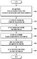
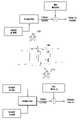
도 1은 본 발명의 일 실시 예에 따라, 사용자가 소지한 단말을 이용하여, 사용자의 위치를 측정하는 방법을 나타내는 도면,
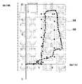
도 2는 본 발명의 일 실시 예에 따라, 신호의 수신 전계 강도를 이용하여 단말의 위치를 예측하는 방법을 설명하기 위한 도면,
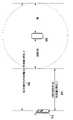
도 3a 내지 도 3c는 본 발명의 일 실시 예에 따라, 각 알고리즘에 적용되는 가중치를 결정하는 방법을 설명하기 위한 도면,
도 4는 본 발명의 일 실시 예에 따라, 단말의 위치를 측정하는 방법을 나타내는 흐름도,
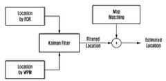
도 5는 본 발명의 일 실시 예에 따라, 단말의 위치를 측정하는 구성을 나타내는 블록도,
도 6은 본 발명의 일 실시 예에 따라, 단말의 복수의 센서를 이용하여 단말의 위치를 측정하고, 상기 측정된 단말의 위치를 보정한 결과를 나타내는 도면,
도 7은 본 발명의 일 실시 예에 따라, 맵 매칭(map matching)을 수행한 결과를 나타내는 도면,
도 8a 및 도 8b는 본 발명의 일 실시 예에 따라, 도어락에 접근하는 사용자 단말을 감지하는 실시 예를 나타내는 도면,
도 9a 내지 도 9c는 본 발명의 일 실시 예에 따라, 사용자의 측정된 위치에 따라 PDR 기술의 온오프(on/off)를 제어하는 방법을 나타내는 도면,
도 10은 본 발명의 일 실시 예에 따라, 상기 PDR 기술의 온오프가 제어되는 방법을 나타내는 도면,
도 11a 및 도 11b는 본 발명의 일 실시 예에 따라, 사용자의 입출에 따라 PDR 기능의 온오프를 제어하는 방법을 나타내는 도면,
도 12는 본 발명의 일 실시 예에 따라, 사용자가 기설정된 공간을 출입했는지 여부에 따라 PDR 기능의 온오프를 제어하는 방법을 나타내는 도면, 그리고
도 13은 본 발명의 일 실시 예에 따른 단말의 구성요소를 도시한 블록도이다.1 is a diagram illustrating a method of measuring a user's location using a terminal possessed by the user, according to an embodiment of the present invention;
2 is a diagram for explaining a method of predicting a location of a terminal using a received electric field strength of a signal according to an embodiment of the present invention;
3A to 3C are diagrams for explaining a method of determining a weight applied to each algorithm according to an embodiment of the present invention;
4 is a flowchart illustrating a method of measuring a location of a terminal according to an embodiment of the present invention;
5 is a block diagram illustrating a configuration for measuring a location of a terminal according to an embodiment of the present invention;
6 is a diagram illustrating a result of measuring a position of a terminal using a plurality of sensors of the terminal and correcting the measured position of the terminal, according to an embodiment of the present invention;
7 is a diagram illustrating a result of performing map matching according to an embodiment of the present invention;
8A and 8B are diagrams illustrating an embodiment of detecting a user terminal approaching a door lock according to an embodiment of the present invention;
9A to 9C are diagrams illustrating a method of controlling on/off of PDR technology according to a measured location of a user, according to an embodiment of the present invention;
10 is a diagram illustrating a method of controlling on/off of the PDR technology according to an embodiment of the present invention;
11A and 11B are diagrams illustrating a method of controlling on/off of a PDR function according to a user's entry/exit according to an embodiment of the present invention;
12 is a diagram illustrating a method of controlling on/off of a PDR function according to whether a user enters or exits a preset space according to an embodiment of the present invention; and
13 is a block diagram illustrating components of a terminal according to an embodiment of the present invention.
본 실시 예들은 다양한 변환을 가할 수 있고 여러 가지 실시 예를 가질 수 있는바, 특정 실시 예들을 도면에 예시하고 상세한 설명에 상세하게 설명하고자 한다. 그러나 이는 특정한 실시 형태에 대해 범위를 한정하려는 것이 아니며, 개시된 사상 및 기술 범위에 포함되는 모든 변환, 균등물 내지 대체물을 포함하는 것으로 이해되어야 한다. 실시 예들을 설명함에 있어서 관련된 공지 기술에 대한 구체적인 설명이 요지를 흐릴 수 있다고 판단되는 경우 그 상세한 설명을 생략한다.Since the present embodiments can apply various transformations and can have various embodiments, specific embodiments are illustrated in the drawings and described in detail in the detailed description. However, this is not intended to limit the scope of the specific embodiments, and it should be understood to include all transformations, equivalents and substitutions included in the spirit and scope of the disclosure. In describing the embodiments, if it is determined that a detailed description of a related known technology may obscure the subject matter, the detailed description thereof will be omitted.
제1, 제2 등의 용어는 다양한 구성요소들을 설명하는데 사용될 수 있지만, 구성요소들은 용어들에 의해 한정되어서는 안 된다. 용어들은 하나의 구성요소를 다른 구성요소로부터 구별하는 목적으로만 사용된다.Terms such as first, second, etc. may be used to describe various elements, but the elements should not be limited by the terms. The terms are used only for the purpose of distinguishing one component from another.
본 출원에서 사용한 용어는 단지 특정한 실시 예를 설명하기 위해 사용된 것으로, 권리범위를 한정하려는 의도가 아니다. 단수의 표현은 문맥상 명백하게 다르게 뜻하지 않는 한, 복수의 표현을 포함한다. 본 출원에서, "포함하다." 또는 "구성되다." 등의 용어는 명세서상에 기재된 특징, 숫자, 단계, 동작, 구성요소, 부품 또는 이들을 조합한 것이 존재함을 지정하려는 것이지, 하나 또는 그 이상의 다른 특징들이나 숫자, 단계, 동작, 구성요소, 부품 또는 이들을 조합한 것들의 존재 또는 부가 가능성을 미리 배제하지 않는 것으로 이해되어야 한다.The terms used in the present application are only used to describe specific embodiments, and are not intended to limit the scope of rights. The singular expression includes the plural expression unless the context clearly dictates otherwise. In this application, "includes." Or "consistent." The term such as is intended to designate that there is a feature, number, step, action, component, part, or combination thereof described in the specification, but one or more other features or number, step, action, component, part or It should be understood that it does not preclude the possibility of the existence or addition of combinations thereof.
실시 예에 있어서 ‘모듈’ 혹은 ‘부’는 적어도 하나의 기능이나 동작을 수행하며, 하드웨어 또는 소프트웨어로 구현되거나 하드웨어와 소프트웨어의 결합으로 구현될 수 있다. 또한, 복수의‘모듈’ 혹은 복수의‘부’는 특정한 하드웨어로 구현될 필요가 있는 ‘모듈’ 혹은 ‘부’를 제외하고는 적어도 하나의 모듈로 일체화되어 적어도 하나의 프로세서(미도시)로 구현될 수 있다.
In an embodiment, a 'module' or 'unit' performs at least one function or operation, and may be implemented as hardware or software, or a combination of hardware and software. In addition, a plurality of 'modules' or a plurality of 'units' are integrated into at least one module and implemented with at least one processor (not shown) except for 'modules' or 'units' that need to be implemented with specific hardware. can be
도 1은 본 발명의 일 실시 예에 따라, 사용자(10)가 소지한 단말(100)을 이용하여, 사용자(10)의 위치를 측정하는 방법을 나타내는 도면이다.1 is a diagram illustrating a method of measuring a location of a
도 1에 도시된 바와 같이, 사용자(10)의 위치를 측정하기 위해, 사용자(10)가 소지한 단말(100) 및 사용자(10)가 존재하는 공간에는 복수개의 전자 장치(110, 120)가 이용될 수 있다.As shown in FIG. 1 , in order to measure the location of the
상기 복수개의 전자 장치(110, 120)는 상기 공간에 기설정된 간격으로 이격되어 설치될 수 있다. 그리고 상기 복수개의 전자 장치(110, 120)는 상기 단말(100)과 신호를 송수신할 수 있다. 따라서, 단말(100)은 상기 복수개의 전자 장치(110, 120)로부터 수신되는 신호의 세기를 측정하여, 상기 단말(100)과 각 전자 장치(110, 120) 사이의 거리를 측정할 수 있다.The plurality of
예를 들면, 상기 복수개의 전자 장치(110, 120)는 AP(access point)와 같이 무선 통신에서 유선망을 상기 공간에 대해 무선망으로 확장시키기 위해 중계 역할을 수행하는 장치일 수 있다.For example, the plurality of
본 발명의 일 실시 예에 따르면, 단말(100)은 제1 위치(130)에서 제3 위치(150)로 이동하면서, 상기 복수개의 전자 장치(110, 120) 각각으로부터 무선 신호를 수신할 수 있다. 도 1은 두 개의 전자 장치(110, 120)만을 도시하였으나, 공간 내에는 두 개 이상의 복수개의 전자 장치가 존재할 수 있다.According to an embodiment of the present invention, the
따라서, 단말(100)은 각각의 전자 장치로부터 수신되는 무선 신호로부터, 상기 단말(100)의 위치를 측정할 수 있다. 또한, 단말(100)의 위치는 정확도가 높아지도록 보정될 수 있다.Accordingly, the
예를 들면, 단말(100)의 이동 방향이 도면 부호 131로 판단되는 경우, 보정을 수행하여 단말(100)의 이동 방향을 도면 부호 132로 결정할 수 있다. 또는, 단말(100)이 제2 위치(140)에 도달하여, 도면 부호 141로 이동하는 것으로 판단되는 경우, 실질적으로 공간 내에서 제2 위치(140)는 벽과 맞닿아 있으며 도면 부호 141방향은 단말(100)을 소지한 사용자(10)가 이동할 수 없는 공간이므로, 보정을 수행하여 단말(100)의 이동 방향을 도면 부호 142로 결정할 수 있다.For example, when it is determined that the moving direction of the
제3 방향(150)의 우측에 문(door)과 같은 단말(100)의 목적지가 존재한다면, 상술한 방법에 의해, 상기 단말(100)은 상기 문으로부터 임계 거리 이내에 근접하였는지 여부를 판단할 수 있게 된다.If the destination of the
본 발명의 또 다른 실시 예에 따르면, 상기 단말(100)이 상기 복수의 전자 장치(110, 120)로부터 수신하는 신호의 세기를 측정하여 상기 단말(100)의 위치를 결정하는 방법뿐만 아니라, 상기 단말(100) 내에 존재하는 복수의 센서를 이용하여 상기 단말(100)의 위치를 결정할 수도 있다.According to another embodiment of the present invention, in addition to the method for determining the location of the
또한, 상기 복수의 전자 장치(110, 120)로부터 수신되는 신호의 세기를 측정하여 결정된 상기 단말(100)의 위치 및 상기 복수의 센서를 이용하여 결정된 상기 단말(100)의 위치를 기반으로 상기 단말(100)의 최종 위치가 결정될 수도 있다.In addition, based on the location of the
한편, 단말(100)이 자신의 위치를 결정하고, 상기 결정된 위치에 따른 동작을 수행하는 것은 일 실시 예에 불과하며, 공간에 존재하는 제어 장치 또는 서버와 같은 외부 장치에서 상기 단말(100)의 위치를 결정하고, 상기 결정된 단말(100)의 위치 결과를 상기 단말(100)로 전송하거나 또는 상기 결정된 위치에 대응하는 동작을 수행할 수도 있다.On the other hand, it is only an embodiment that the
상술한 방법에 의해, 단말이 존재하는 공간에 추가적인 장치 및 설비 없이도 단말의 위치를 정확하게 결정할 수 있게 된다.By the above-described method, it is possible to accurately determine the location of the terminal without additional devices and facilities in the space where the terminal is present.
이하에서는 단말의 위치를 결정하는 방법에 대해 구체적으로 설명한다.Hereinafter, a method for determining the location of the terminal will be described in detail.
도 2는 본 발명의 일 실시 예에 따라, 신호의 수신 전계 강도(Received Signal Strength Indicator, RSSI)를 이용하여 단말의 위치를 예측하는 방법을 설명하기 위한 도면이다. 단말은 사용자에 의해 소지 되며, 임의의 공간 내에 위치하는 것으로 가정한다. 또한, 상기 임의의 공간 내에는 기 설치된 복수개의 전자 장치(예를 들면, AP)가 존재하는 것으로 가정한다.2 is a diagram for explaining a method of predicting a location of a terminal using a received signal strength indicator (RSSI) of a signal, according to an embodiment of the present invention. It is assumed that the terminal is carried by the user and is located in an arbitrary space. Also, it is assumed that a plurality of pre-installed electronic devices (eg, APs) exist in the arbitrary space.
신호의 수신 전계 강도(RSSI)가 이용되는 것은 일 실시 예에 불과하며, 상기 단말 및 상기 복수개의 전자 장치 사이의 송수신 되는 신호의 세기를 측정할 수 있는 다양한 지표가 이용될 수 있다.The use of the received electric field strength (RSSI) of a signal is only an embodiment, and various indicators for measuring the strength of a signal transmitted/received between the terminal and the plurality of electronic devices may be used.
단말은 복수 개의 전자 장치로부터 수신되는 신호의 RSSI를 측정할 수 있다.The terminal may measure the RSSI of signals received from a plurality of electronic devices.
단말은 복수 개의 AP로부터 수신되는 신호의 RSSI를 측정할 수 있다. 하기의 수학식 1은 자유 공간에서 전파 손실을 나타내는 경로 손실(path loss) 모델을 나타낸 수학식이다.The terminal may measure the RSSI of signals received from a plurality of APs.

상기 수학식 1의 A는 각 AP에 따라 결정되는 파라미터이며, n은 상기 단말이 존재하는 공간의 레이아웃에 따라 결정되는 파라미터일 수 있다.A in
그리고 단말은 상기 수학식 1 및 하기의 수학식 2에 따라, 상기 측정된 RSSI를 이용하여, 상기 단말 및 상기 각 AP 사이의 거리를 계산할 수 있다.In addition, the UE may calculate the distance between the UE and each AP by using the measured RSSI according to

상기 수학식 1 및 수학식 2서, d는 상기 단말 및 상기 AP 간의 거리이고, 상기

단말이 n개의 AP로부터 수신된 신호로부터, n개의 RSSI 값(200)을 측정한 경우를 예로 든다. 상기 n개의 RSSI 값(200)에 기 설정된 복수 개의 알고리즘이 적용되기 위해, 상기 n개의 RSSI 값(200)은 입력단(210)에 입력될 수 있다. A case in which the terminal measures n RSSI values 200 from signals received from n APs is an example. In order to apply a plurality of preset algorithms to the n RSSI values 200 , the n RSSI values 200 may be input to the
도 2는 기 설정된 복수 개의 알고리즘이 네 개의 알고리즘인 예시를 나타낸다. 따라서, 상기 n개의 RSSI 값(200)은 각각 제1 알고리즘 적용부 내지 제4 알고리즘 적용부(221 내지 224)로 입력될 수 있다.2 shows an example in which the plurality of preset algorithms are four algorithms. Accordingly, the n RSSI values 200 may be input to the first to fourth
상기 제1 알고리즘 적용부 내지 제4 알고리즘 적용부(221 내지 224)를 통해, 단말은 각 알고리즘에 따라 도출된 예비 위치들(231 내지 234)을 확인할 수 있다.Through the first algorithm application unit to the fourth
상기 제1 알고리즘 내지 상기 제4 알고리즘의 구체적인 예시에 대해 설명한다. 먼저, 제1 알고리즘은 세 개 이상의 복수 개의 AP에 대해, 각각 단말과 상기 AP 사이의 경로 손실(path loss) 모델 및 거리 공식(상기 수학식 1 및 수학식 2)을 이용하여 단말의 위치를 계산하는 알고리즘이다. 예를 들면, 상기 제1 알고리즘은 삼변 측량과 같은 방식의 알고리즘일 수 있다.Specific examples of the first to fourth algorithms will be described. First, the first algorithm calculates the location of the terminal by using a path loss model and a distance formula (
제2 알고리즘은 상기 제1 알고리즘과 같은 방법에, 상기 RSSI의 강도에 따라 가중치를 주는 방법일 수 있다. 예를 들면, 상기 제2 알고리즘은 높은 강도의 신호를 전송한 AP일수록 높은 신뢰도를 부여하는 방법일 수 있다.The second algorithm may be a method of giving a weight according to the strength of the RSSI to the same method as the first algorithm. For example, the second algorithm may be a method of imparting higher reliability to an AP that has transmitted a signal having a higher strength.
제3 알고리즘은 공간 내의 임의의 지점과 상기 복수 개의 AP 사이의 경로 손실(path loss) 모델 및 거리 공식(상기 수학식 1 및 수학식 2)을 이용하여, 단말이 상기 공간 내의 복수개의 임의의 지점에 존재한다는 가정하에 각 지점과 각 AP 간의 RSSI를 수학적으로 먼저 계산한 결과를 이용하는 알고리즘이다.The third algorithm uses a path loss model and a distance formula (
제3 알고리즘에 의하면, 상기 예측된 복수 지점의 RSSI값을 상기 공간 내에서 위치를 측정하기 위한 단말이 각 AP로부터 측정한 RSSI 값과 비교할 수 있다. 그리고 상기 예측된 복수개의 RSSI 값과 상기 기 측정된 RSSI 값 사이의 유클리드 에러(Euclidean Error)가 최소가 되는 지점을 단말의 위치로 간주할 수 있다.According to the third algorithm, the predicted RSSI values of the plurality of points may be compared with the RSSI values measured from each AP by the terminal for measuring the location in the space. In addition, a point at which a Euclidean error between the predicted plurality of RSSI values and the pre-measured RSSI values is minimized may be regarded as the location of the terminal.
제4 알고리즘은 최소 네 개 이상의 AP와 단말기 사이의 경로 손실(path loss) 모델 및 거리 공식(상기 수학식 1 및 수학식 2)을 이용하여 각 거리 d를 계산하고, 상기 거리 간의 비율에 대한 네 개 이상의 방정식으로부터 상기 단말의 위치를 계산하기 위한 알고리즘이다.The fourth algorithm calculates each distance d using a path loss model and a distance formula (
한편, 상기 제1 내지 제4 알고리즘은 예시에 불과하며, 상기 AP 및 단말 사이의 RSSI 및 거리를 나타낼 수 있는 다양한 알고리즘이 사용될 수 있다. 따라서, 단말은 상기 n개의 RSSI 값(200)으로부터 각 알고리즘을 통해 단말의 위치를 복수 개 확인할 수도 있다. 예를 들면, 도 2에 도시된 바와 같이 예비 위치는


단말은 상기 예비 위치(231 내지 234) 각각에 대해, 기 결정된 가중치(241 내지 244)를 적용하여 제1 추정 위치(250)를 확인할 수 있다.The terminal may check the first estimated
상기 가중치는, 기설정된 시간 간격으로 상기 복수의 전자 장치로부터 신호를 수신하여 상기 RSSI를 측정하고, 상기 측정된 복수의 RSSI 값에 대해, 각각 상기 복수 개의 알고리즘을 적용하고, 상기 복수 개의 알고리즘을 적용한 값 및 실제 상기 단말의 위치 값의 에러율을 확인하여, 상기 확인된 에러율에 따라 결정될 수 있다.The weights are measured by receiving signals from the plurality of electronic devices at preset time intervals, and applying the plurality of algorithms to the plurality of measured RSSI values, respectively, and applying the plurality of algorithms. By checking the error rate of the value and the actual position value of the terminal, it may be determined according to the checked error rate.
상기 n개의 AP로부터 RSSI 값을 측정하는 단계부터 가중치를 계산하는 단계까지 여러 번 반복하면서 평균 RSSI값을 계산하여 최종적으로 안정적인 가중치 값으로 수렴하도록 산출해낼 수 있다.From the step of measuring the RSSI value from the n APs to the step of calculating the weight, the average RSSI value is calculated while repeating several times, and finally it can be calculated to converge to a stable weight value.
구체적으로, 상기 가중치(241 내지 244)는 서로 다른 알고리즘 각각에 대해 미리 결정된 값일 수 있다. 알고리즘이 네 개 이상 존재하는 경우, 상기 가중치도 네 개 이상 존재할 수도 있다.Specifically, the
따라서, 단말은 상기 예비 위치(231 내지 234)에 대해 기 결정된 가중치를 각각 적용할 수 있다. 예를 들면, 단말은 제1 예비 위치


상기 가중치(241 내지 244)는 1보다 작은 값으로, 각 알고리즘에 대한 가중치(241 내지 244)들을 합산하면 1이 될 수 있다. 또한, 상기 가중치는 상기 단말의 위치를 결정하는 동작을 수행하기 전에 이미 결정되어 있을 수 있다. 상기 가중치가 결정되는 구체적인 방법은 후술한다.The
단말은 결정된 예비 위치(231 내지 234) 각각에 대해, 기 결정된 가중치(241 내지 244)를 적용한 값을 좌표별로 합산함으로써, 제1 추정 위치(250)를 확인할 수 있다. 예를 들면, 단말은 제1 예비 위치(231)의 x좌표에 기 결정된 가중치(241)가 적용된 값, 제2 예비 위치(232)의 x좌표에 기 결정된 가중치(242)가 적용된 값, 제3 예비 위치(233)의 x좌표에 기 결정된 가중치(243)가 적용된 값 및 제4 예비 위치(234)의 x좌표에 기 결정된 가중치(244)가 적용된 값을 합산하여, 제1 추정 위치(250)의 x좌표 값을 결정할 수 있다. 또한, 단말은 제1 예비 위치(231)의 y좌표에 기 결정된 가중치(241)가 적용된 값, 제2 예비 위치(232)의 y좌표에 기 결정된 가중치(242)가 적용된 값, 제3 예비 위치(233)의 y좌표에 기 결정된 가중치(243)가 적용된 값 및 제4 예비 위치(234)의 y좌표에 기 결정된 가중치(244)가 적용된 값을 합산하여, 제1 추정 위치(250)의 y좌표 값을 결정할 수 있다.The terminal may check the first estimated
상기 제1 추정 위치(250)는 상기 단말의 최종 위치를 결정하는데 이용될 수 있다.The first estimated
한편, 도 3a 및 도 3c를 참조하여, 상기 가중치(241 내지 244)가 결정되는 방법을 설명한다.Meanwhile, a method in which the
먼저, 단말은 임의의 공간(300) 내에 존재하는 것으로 가정한다. 도 3a에 도시된 바와 같이, 상기 공간(300)에는 복수 개의 전자 장치(301, 302, 303, …)가 존재할 수 있다. 도 3a 및 도 3b는 공간(300) 내에 전자 장치가 열여섯 개가 존재하는 것으로 도시되었으나, 이는 일 실시 예에 불과할 뿐, 이에 한정되지 않는다.First, it is assumed that the terminal exists in an
가중치를 결정하기 위해, 단말은 제1 위치(310)에서 상기 복수 개의 전자 장치(301, 302, 303, …)로 부터 신호를 수신할 수 있다. 그리고 단말은 상기 제1 위치(310)에서 각 전자 장치로부터 수신되는 신호의 세기를 측정할 수 있다. 예를 들면, 단말은 각 전자 장치로부터 수신되는 신호의 제1 RSSI 값들(311, 312, 313, …)을 측정할 수 있다.In order to determine the weight, the terminal may receive signals from the plurality of
그리고 상기 단말은 상기 제1 RSSI 값들(311, 312, 313, …)에 대해 기 설정된 복수 개의 알고리즘을 적용할 수 있다. 상기 단말은 각각의 알고리즘에 따라 상기 단말의 위치를 획득할 수 있다. 예를 들어, 상기 복수 개의 알고리즘이 네 가지의 알고리즘인 경우, 상기 단말은 네 가지 알고리즘 각각을 이용하여 상기 RSSI 값들(311, 312, 313, …)을 기반으로 네 가지의 단말의 위치를 결정할 수 있다. 이때, 알고리즘에 따라 상기 단말의 위치에 대한 결과는 상이할 수도 있다.In addition, the terminal may apply a plurality of preset algorithms to the first RSSI values 311, 312, 313, .... The terminal may obtain the location of the terminal according to each algorithm. For example, when the plurality of algorithms are four algorithms, the terminal can determine the positions of the four terminals based on the RSSI values 311, 312, 313, ... using each of the four algorithms. have. In this case, the results for the location of the terminal may be different depending on the algorithm.
복수 개의 알고리즘을 이용하여 단말의 위치가 결정되면, 도 3b에 도시된 바와 같이, 상기 단말은 제2 위치(320)에서 다시 상기 복수 개의 전자 장치(301, 302, 303, …)로 부터 신호를 수신할 수 있다. 그리고 단말은 상기 복수 개의 전자 장치(301, 302, 303, …)로부터 수신되는 신호의 제2 RSSI 값들(321, 322, 323, …)을 측정할 수 있다.When the location of the terminal is determined using a plurality of algorithms, as shown in FIG. 3b , the terminal receives signals from the plurality of
상기 제2 RSSI 값들(321, 322, 323, …)에 대해서도 마찬가지로, 상기 단말은 기 설정된 복수 개의 알고리즘을 적용할 수 있다. 상기 단말은 각각의 알고리즘에 따라 상기 단말의 위치를 복수 개 획득할 수 있다.Similarly to the second RSSI values 321, 322, 323, ..., the terminal may apply a plurality of preset algorithms. The terminal may acquire a plurality of locations of the terminal according to each algorithm.
가중치를 결정하기 위해, 상기 단말이 상술한 방법에 의해 각각의 위치에서 복수 개의 전자 장치(301, 302, 303, …)로 부터 신호를 수신하여 상기 단말의 위치를 획득하는 동안, 상기 단말은 자신의 위치를 알고 있다. 따라서, 상기 단말은 알고 있는 자신의 위치가 상기 신호를 수신하여 획득한 상기 단말의 위치가 일치하는지 여부를 판단할 수 있다.In order to determine the weight, while the terminal acquires the location of the terminal by receiving signals from a plurality of
상기 단말이 도 3a의 제1 위치(310)에서 도 3b의 제2 위치(320)를 거쳐 계속 공간(300)의 오른쪽으로 이동한 경우를 예로 든다. 가중치를 결정하기 위해 전술한 동작을 수행하는 동안 단말은 자신의 위치 및 이동 경로를 알고 있을 수 있다.A case in which the terminal continuously moves from the
그리고 도 3c는 전술한 방법에 의해, 단말이 네 가지의 알고리즘 각각을 이용하여 획득한 단말의 이동 방향을 나타낸 테이블의 예시이다.And FIG. 3c is an example of a table showing the movement direction of the terminal obtained by the terminal using each of the four algorithms by the above-described method.
도 3c에 도시된 바와 같이, 제1 및 제2 알고리즘을 통해 획득한 단말의 위치 및 이에 따른 이동 방향은 단말의 실제 이동 방향과 같이 계속 오른쪽으로 나타날 수 있다.As shown in FIG. 3C , the position of the terminal obtained through the first and second algorithms and the corresponding movement direction may continue to appear to the right like the actual movement direction of the terminal.
그러나 제3 알고리즘을 통해 획득한 단말의 위치 및 이에 따른 이동 방향은 두 번째 이동 방향을 획득했을 때, 단말의 실제 이동 방향과 달리 왼쪽으로 향하는 것을 볼 수 있다.However, it can be seen that the position of the terminal obtained through the third algorithm and the movement direction according to it are directed to the left, unlike the actual movement direction of the terminal, when the second movement direction is obtained.
또한, 제4 알고리즘을 통해 획득한 단말의 위치 및 이에 따른 이동 방향은 두 번째 및 세 번째 이동 방향을 획득했을 때, 단말의 실제 이동 방향과 달리 왼쪽으로 향하는 것을 볼 수 있다.In addition, it can be seen that the position of the terminal obtained through the fourth algorithm and the movement direction thereof are directed to the left, unlike the actual movement direction of the terminal, when the second and third movement directions are obtained.
상기와 같은 결과를 획득한 단말은, 실제 이동 방향과 알고리즘을 통해 획득한 결과가 높은 일치 율을 보인 순서로 가중치를 크게 결정할 수 있다. 예를 들면, 단말은 실제 이동 방향과 알고리즘을 통해 획득한 결과가 가장 정확하게 일치하는 상기 제1 알고리즘 및 상기 제2 알고리즘에 대해 가중치를 0.3으로 결정할 수 있다. 그리고 단말은 다음으로 높은 일치 율을 보인 제3 알고리즘에 대한 가중치를 0.25로 결정하고, 가장 낮은 일치 율을 보인 제4 알고리즘에 대한 가중치를 0.15로 결정할 수 있다.The terminal, which has obtained the above result, can determine the weights in the order in which the actual movement direction and the result obtained through the algorithm show a high coincidence rate. For example, the terminal may determine a weight of 0.3 for the first algorithm and the second algorithm in which the actual movement direction and the result obtained through the algorithm most accurately match. In addition, the UE may determine a weight for the third algorithm having the next highest matching rate as 0.25, and may determine a weight for the fourth algorithm having the lowest matching rate as 0.15.
한편, 상기 단말의 위치 및 상기 단말의 이동 경로를 미리 알고 있으면서, 상술한 바와 같은 방법에 의해 상기 단말의 이동 방향을 각각의 알고리즘을 통해 측정하는 주체가 상기 단말인 것은 일 실시 예에 불과할 뿐, 서버와 같은 외부의 장치일 수도 있다.On the other hand, it is only an embodiment that the terminal is the subject that measures the movement direction of the terminal through each algorithm by the method as described above while knowing the location of the terminal and the movement path of the terminal in advance, It may be an external device such as a server.
도 4는 본 발명의 일 실시 예에 따라, 단말의 위치를 측정하는 방법을 나타내는 흐름도이다. 도 4를 참고하여, 상기 단말의 최종 위치를 결정하는 방법을 설명한다.4 is a flowchart illustrating a method of measuring a location of a terminal according to an embodiment of the present invention. A method of determining the final location of the terminal will be described with reference to FIG. 4 .
먼저, 단계 S400에서, 단말은 공간 내에 존재하는 복수의 전자 장치로부터 수신하는 신호의 수신 전계 강도 (received signal strength indicator, RSSI) 를 측정할 수 있다.First, in step S400, the terminal may measure a received signal strength indicator (RSSI) of signals received from a plurality of electronic devices existing in a space.
구체적으로, 단말의 위치를 측정하기 위해, 상기 단말이 존재하는 공간에는 복수개의 전자 장치가 이용될 수 있다. 상기 복수개의 전자 장치는 상기 공간에 기설정된 간격으로 이격되어 설치될 수 있다. 그리고 상기 복수개의 전자 장치는 상기 단말과 신호를 송수신할 수 있다. 따라서, 단말은 상기 복수개의 전자 장치로부터 수신되는 신호의 세기를 측정하여, 상기 단말과 각 전자 장치 사이의 거리를 측정할 수 있다.Specifically, in order to measure the location of the terminal, a plurality of electronic devices may be used in a space in which the terminal is present. The plurality of electronic devices may be installed to be spaced apart from each other at a predetermined interval in the space. In addition, the plurality of electronic devices may transmit/receive signals to and from the terminal. Accordingly, the terminal may measure the intensity of signals received from the plurality of electronic devices to measure the distance between the terminal and each electronic device.
예를 들면, 상기 복수개의 전자 장치는 AP(access point)와 같이 무선 통신에서 유선망을 상기 공간에 대해 무선망으로 확장시키기 위해 중계 역할을 수행하는 장치일 수 있다.For example, the plurality of electronic devices may be devices that perform a relay role to extend a wired network into a wireless network for the space in wireless communication, such as an access point (AP).
신호의 수신 전계 강도(RSSI)가 이용되는 것은 일 실시 예에 불과하며, 상기 단말 및 상기 복수개의 전자 장치 사이의 송수신 되는 신호의 세기를 측정할 수 있는 다양한 지표가 이용될 수 있다.The use of the received electric field strength (RSSI) of a signal is only an embodiment, and various indicators for measuring the strength of a signal transmitted/received between the terminal and the plurality of electronic devices may be used.
단계 S410에서, 단말은 상기 측정된 복수 개의 RSSI 값에 기 설정된 복수 개의 알고리즘을 적용할 수 있다. 그리고 단계 S420에서, 단말은 상기 복수 개의 알고리즘 각각에 대한 단말의 예비 위치를 도출할 수 있다.In step S410, the terminal may apply a plurality of preset algorithms to the plurality of measured RSSI values. And in step S420, the terminal may derive the preliminary location of the terminal for each of the plurality of algorithms.
단말이 네 가지 알고리즘을 이용하여 상기 단말의 위치를 결정하는 경우를 예로 든다. 단말은 상기 측정된 복수 개의 RSSI 값에 제1 알고리즘을 적용하여 제1 예비 위치를 도출하고, 상기 측정된 복수 개의 RSSI 값에 제2 알고리즘을 적용하여 제2 예비 위치를 도출할 수 있다. 그리고 단말은 상기 측정된 복수 개의 RSSI 값에 제3 알고리즘을 적용하여 제3 예비 위치를 도출하고, 상기 측정된 복수 개의 RSSI 값에 제4 알고리즘을 적용하여 제4 예비 위치를 도출할 수 있다.A case in which the terminal determines the location of the terminal using four algorithms is taken as an example. The terminal may derive a first preliminary position by applying a first algorithm to the plurality of measured RSSI values, and may derive a second preliminary position by applying a second algorithm to the plurality of measured RSSI values. In addition, the terminal may derive a third preliminary position by applying a third algorithm to the plurality of measured RSSI values, and may derive a fourth preliminary position by applying a fourth algorithm to the plurality of measured RSSI values.
제1 알고리즘은 세 개 이상의 복수 개의 AP에 대해, 각각 단말과 상기 AP 사이의 경로 손실(path loss) 모델 및 거리 공식(상기 수학식 1 및 수학식 2)을 이용하여 단말의 위치를 계산하는 알고리즘이다. 예를 들면, 상기 제1 알고리즘은 삼변 측량과 같은 방식의 알고리즘일 수 있다.The first algorithm is an algorithm for calculating the location of the terminal using a path loss model and a distance formula (
제2 알고리즘은 상기 제1 알고리즘과 같은 방법에, 상기 RSSI의 강도에 따라 가중치를 주는 방법일 수 있다. 예를 들면, 상기 제2 알고리즘은 높은 강도의 신호를 전송한 AP일수록 높은 신뢰도를 부여하는 방법일 수 있다.The second algorithm may be a method of giving a weight according to the strength of the RSSI to the same method as the first algorithm. For example, the second algorithm may be a method of imparting higher reliability to an AP that has transmitted a signal having a higher strength.
제3 알고리즘은 공간 내의 임의의 지점과 상기 복수 개의 AP 사이의 경로 손실(path loss) 모델 및 거리 공식(상기 수학식 1 및 수학식 2)을 이용하여, 단말이 상기 공간 내의 복수개의 임의의 지점에 존재한다는 가정하에 각 지점과 각 AP 간의 RSSI를 수학적으로 먼저 계산한 결과를 이용하는 알고리즘이다.The third algorithm uses a path loss model and a distance formula (
제3 알고리즘에 의하면, 상기 예측된 복수지점의 RSSI값을 상기 공간 내에서 위치를 측정하기 위한 단말이 각 AP로부터 측정한 RSSI 값과 비교할 수 있다. 그리고 상기 예측된 복수개의 RSSI 값과 상기 기 측정된 RSSI 값 사이의 유클리드 에러(Euclidean Error)가 최소가 되는 지점을 단말의 위치로 간주할 수 있다.According to the third algorithm, the predicted RSSI value of the multiple points may be compared with the RSSI value measured by the terminal for measuring the location in the space from each AP. In addition, a point at which a Euclidean error between the predicted plurality of RSSI values and the pre-measured RSSI values is minimized may be regarded as the location of the terminal.
제4 알고리즘은 최소 네 개 이상의 AP와 단말기 사이의 경로 손실(path loss) 모델 및 거리 공식(상기 수학식 1 및 수학식 2)을 이용하여 각 거리 d를 계산하고, 상기 거리 간의 비율에 대한 네 개 이상의 방정식으로부터 상기 단말의 위치를 계산하기 위한 알고리즘이다.The fourth algorithm calculates each distance d using a path loss model and a distance formula (
한편, 상기 제1 내지 제4 알고리즘은 예시에 불과하며, 상기 AP 및 단말 사이의 RSSI 및 거리를 나타낼 수 있는 다양한 알고리즘이 사용될 수 있다.Meanwhile, the first to fourth algorithms are merely examples, and various algorithms capable of representing the RSSI and distance between the AP and the terminal may be used.
따라서, 단말은 상기 측정된 복수 개의 RSSI 값으로부터 각 알고리즘을 통해 단말의 예비 위치를 복수 개 확인할 수 있다.Accordingly, the terminal may identify a plurality of preliminary positions of the terminal through each algorithm from the plurality of measured RSSI values.
단계 S430에서, 단말은 상기 예비 위치 각각에 대해, 기 결정된 가중치를 적용하여 제1 추정 위치를 확인할 수 있다.In step S430, the terminal may check the first estimated position by applying a predetermined weight to each of the preliminary positions.
구체적으로, 상기 가중치는 서로 다른 알고리즘 각각에 대해 미리 결정된 값일 수 있다. 알고리즘이 네 개 이상 존재하는 경우, 상기 가중치도 네 개 이상 존재할 수도 있다. 따라서, 단말은 상기 제1 내지 제4 예비 위치에 대해 기 결정된 가중치를 각각 적용할 수 있다.Specifically, the weight may be a predetermined value for each of the different algorithms. When four or more algorithms exist, four or more weights may exist. Accordingly, the terminal may apply a predetermined weight to each of the first to fourth reserved positions.
상기 가중치는 상기 단말의 위치를 결정하는 동작을 수행하기 전에 이미 결정되어 있을 수 있다. 상기 가중치를 결정하는 방법은 전술한 바와 같다.The weight may have already been determined before the operation of determining the location of the terminal is performed. A method of determining the weight is the same as described above.
또한, 단계 S440에서, 단말은 적어도 하나의 센서를 이용하여, 상기 단말의 제2 추정 위치를 확인할 수 있다. 예를 들면, 단말은 보행자 추측 항법(Pedestrian Dead Reckoning, PDR) 기술을 이용하여, 상기 제2 추정 위치를 확인할 수 있다.Also, in step S440, the terminal may use at least one sensor to determine the second estimated location of the terminal. For example, the terminal may determine the second estimated location by using a Pedestrian Dead Reckoning (PDR) technique.
구체적으로, 단말은 지자기 센서, 자이로스코프 센서 및 가속도 센서와 같은 복수의 센서를 포함할 수 있다. 따라서, 단말은 상기 복수의 센서를 이용하여 상기 단말이 이동하는 속도, 방향, 이전 측정 지점으로부터의 상대적인 위치 등을 결정할 수 있다.Specifically, the terminal may include a plurality of sensors such as a geomagnetic sensor, a gyroscope sensor, and an acceleration sensor. Accordingly, the terminal may determine the speed, direction, and relative position from the previous measurement point, etc. at which the terminal moves by using the plurality of sensors.
그리고 단계 S450에서, 단말은 상기 제1 및 제2 추정 위치에 기반하여 상기 단말의 최종 위치를 결정할 수 있다. 예를 들면, 상술한 보행자 추측 항법 기술은 센서에 의한 측위 오차가 누적될 수도 있다. 이에 따라, 출발 지점에서 거리가 멀어지면 보정이 필요할 수도 있다. 따라서, 상기 보행자 추측 항법 기술에 의해 결정된 제2 추정 위치 및 상기 제1 추정 위치를 함께 이용하여 상기 단말의 최종 위치가 결정될 수 있다.And in step S450, the terminal may determine the final location of the terminal based on the first and second estimated positions. For example, in the above-described pedestrian dead reckoning technique, a positioning error by a sensor may be accumulated. Accordingly, if the distance from the starting point increases, correction may be required. Accordingly, the final position of the terminal may be determined by using the second estimated position determined by the pedestrian dead reckoning technique and the first estimated position together.
한편, 도 5는 본 발명의 일 실시 예에 따라, 단말의 위치를 측정하는 구성을 나타내는 블록도이다.Meanwhile, FIG. 5 is a block diagram illustrating a configuration for measuring a location of a terminal according to an embodiment of the present invention.
블록 501 내지 503은 단말 내에 존재하는 자기 센서, 자이로스코프 센서 및 가속도 센서를 각각 이용하여 데이터를 수집하는 구성요소를 나타낸다. 상기 자기 센서, 자이로스코프 센서 및 가속도 센서는 일 실시 예에 불과할 뿐, 상기 단말은 다른 종류의 다양한 센서를 구비하고, 데이터를 수집할 수 있다.
블록 510에서, 상술한 바와 같이 자기 센서, 자이로스코프 센서 및 가속도 센서를 각각 이용하여 수집된 데이터를 이용하여, 보행자 추측 항법(PDR) 기술에 의해, 상기 단말의 추정 위치를 결정할 수 있다.In
도 6은 일 실시 예에 따라, 상기 PDR 기술 및 전술한 방법에 의해 단말의 위치를 추정한 결과를 도시한 도면이다. 도면 부호 600은 복수의 센서를 통해 상술한 바와 같은 데이터를 수집하고, 상기 PDR에 의해 단말의 위치를 추정한 결과를 나타낸다.6 is a diagram illustrating a result of estimating a location of a terminal by the PDR technique and the above-described method, according to an embodiment.
한편, 도 6에 도시된 바와 같이, 전술한 방법에 의해, 더욱 정확한 단말의 위치를 추정할 수 있음을 알 수 있다. 다만, 도면 부호 610에서 알 수 있듯이 PDR은 센서에 의한 측위 오차가 누적될 수도 있으므로, 출발 지점에서 거리가 멀어지면 보정이 필요할 수도 있다.Meanwhile, as shown in FIG. 6 , it can be seen that the location of the terminal can be more accurately estimated by the above-described method. However, as can be seen from
다시 도 5에 대해 설명하면, 블록 520에서, 단말은 상기 단말이 존재하는 공간의 복수 개의 전자 장치로부터 수신되는 신호의 세기를 측정할 수 있다. 도 5에 도시된 바와 같이, 단말은 공간에 기 설치된 복수 개의 AP로부터 수신되는 와이파이(wifi) 신호의 수신 전계 강도(RSSI)를 측정할 수 있다.Referring back to FIG. 5 , in
또한, 블록 530에서, 단말은, 전술한 방법에 의해, 상기 측정된 RSSI를 이용하여 단말의 위치를 추정 결정할 수 있다. 전술한 바와 같이, 상기 측정된 RSSI를 복수 개의 알고리즘을 각각 적용하고, 상기 각각의 알고리즘을 통해 획득한 예비 위치에 대해 알고리즘에 따라 기결정된 가중치를 적용함으로써, 단말은 추정 위치를 확인할 수 있다.Also, in
상기와 같이 단말의 추정 위치를 확인하는 방법을 Weighted Propagation Model(WPM)이라 명명하면, 상기 블록 530에서 상기 WPM에 의해 단말의 추정 위치가 확인될 수 있다.If the method of confirming the estimated location of the terminal as described above is called Weighted Propagation Model (WPM), the estimated location of the terminal may be confirmed by the WPM in
PDR 기술에 의해 결정된 단말의 추정 위치 및 WPM 기술에 의해 결정된 단말의 추정 위치는, 블록 540에서, 칼만 필터(kalman filter)에 의해 혼합될 수 있다. 칼만 필터는 공지기술인 바 구체적인 설명은 생략한다.The estimated position of the terminal determined by the PDR technique and the estimated position of the terminal determined by the WPM technique may be mixed by a Kalman filter in
한편, 칼만 필터가 사용되는 것은 일 실시 예에 불과할 뿐, 파티클 필터(particle filter)와 같은 다양한 필터가 사용될 수도 있다.Meanwhile, the use of the Kalman filter is only an exemplary embodiment, and various filters such as a particle filter may be used.
맵 매칭(map matching) 블록(550)은 상기 필터를 통해 결정된 단말의 위치에 대해 보정을 수행할 수 있다. 따라서, 단말은 필터링 된 단말의 위치 및 상기 맵 매칭을 통한 결과를 이용하여 최종 위치(560)를 결정할 수 있다.The
예를 들면, 도 7에 도시된 바와 같이 맵 매칭(map matching)이 수행될 수 있다. 구체적으로, 단말은, 도 7에 도시된 바와 같은, 상기 단말이 존재하는 공간에 대한 맵(700)을 미리 저장하고 있을 수 있다. 예를 들면, 상기 단말은 상기 공간의 벽과 바닥, 가구의 배치, 문과 창문의 위치 등에 대한 정보를 포함하는 맵을 저장할 수 있다. 단말은 상기 맵(700)에 의해, 단말을 소지한 사용자가 보행할 수 없는 제약(Constraint)에 대한 데이터를 저장할 수 있다. 그리고 단말은 측정된 사용자의 위치가 상기 제약(Constraint)과 중첩하는 경우, 상기 측정된 사용자의 위치를 상기 사용자가 존재할 수 있는 위치로 보정할 수 있다.For example, map matching may be performed as shown in FIG. 7 . Specifically, the terminal may have previously stored a
전술한 방법에 의해 측정한 단말의 위치가 임의의 시간 동안 도 7의 도면부호 710 내지 도면부호 713으로 측정된 경우, 단말은 상기 측정된 위치를 상기 맵(700)과 비교할 수 있다. 맵(700)에 의하면, 단말은 도면부호 713의 위치는 공간 내에 가구(책상)가 존재하는 위치인 것으로 판단할 수 있다. 따라서, 단말은 상기 단말의 측정된 위치를 도면부호 710 내지 712의 이동 방향 및 상기 맵(700)을 기반으로, 도면부호 714로 보정할 수 있다.When the location of the terminal measured by the above-described method is measured by
본 발명의 다른 실시 예에 따라, 단말의 위치가 임의의 시간 동안 도 7의 도면부호 720 내지 도면부호 723으로 측정된 경우, 단말은 상기 측정된 위치를 상기 맵(700)과 비교할 수 있다. 맵(700)에 의하면, 단말은 도면부호 723의 위치 또한 공간 내에 가구(책상)가 존재하는 위치인 것으로 판단할 수 있다. 따라서, 단말은 상기 단말의 측정된 위치를 도면부호 720 내지 722의 이동 방향, 진입각 및 상기 맵(700)을 기반으로, 도면부호 724로 보정할 수 있다.According to another embodiment of the present invention, when the location of the terminal is measured by
이하에서는 도 8 내지 도 12를 바탕으로, 상술한 방법에 의해 측정한 사용자의 위치를 활용하는 구체적인 방안에 대해 설명한다. 이하에서는, 상술한 방법과 같은 위치 측정 방법을 PDR 기술과 WPM 기술이 동시에 사용되었음을 이유로 하이브리드 위치 측정(hybrid localization) 방법으로 명명한다.Hereinafter, a detailed method of utilizing the user's location measured by the above-described method will be described with reference to FIGS. 8 to 12 . Hereinafter, a location measurement method such as the above-described method is named a hybrid localization method because the PDR technology and the WPM technology are used at the same time.
도 8a는 본 발명의 일 실시 예에 따라, 도어 락(810)에 접근하는 사용자(80)를 도시한 도면이다. 상기 도어 락(810)은 호텔의 객실 문이며, 상기 사용자(80)는 소지한 스마트 폰(800)을 이용하여 스마트 키로 상기 도어 락(810)을 오픈하는 경우를 예로 든다.8A is a diagram illustrating a
구체적으로, 체크인을 수행하면서, 스마트 키를 스마트 폰(800)에 발급받은 사용자는 상기 도어 락(810)에서 임계 거리 이내에 접근하는 경우, 상기 스마트 폰(810)을 이용하여 상기 도어 락(810)에 접근하였다는 알림을 확인할 수 있다.Specifically, when a user who has been issued a smart key to the
사용자의 보행 속도를 고려했을 때, 사용자(800)가 도어 락(810)으로부터 3m 거리(820)에 존재할 때, 스마트 키의 발급이 시작되어야 사용자(800)가 도어 락(810)에 도착하기 전에 스마트 키의 발급 및 전달이 완료되고, 사용자(800)는 스마트 키를 이용하여 인증 및 자동 열림 서비스를 제공받을 수 있게 된다.Considering the walking speed of the user, when the
따라서, 상기 도어 락(810)으로부터 3m(820) 및 임계 거리(예를 들면, 10m(830)) 이내에 사용자(800)가 존재하는 경우, 스마트 폰(800)에 상기 도어 락(810)에 접근하였다는 알림이 전송될 필요가 있다.Accordingly, when the
하이브리드 위치 측정 방법에 의해, 사용자의 위치를 측정하는 경우, 상기 스마트 폰(800)에, 상기 도어 락(810)에 접근하였다는 알림이 상기 도어 락(810)으로부터 3m(820) 및 임계 거리(예를 들면, 10m(830)) 이내에 사용자(800)가 존재할 때 전송되는, 정확도가 향상될 수 있다.When the user's location is measured by the hybrid location measurement method, a notification indicating that the
한편, 도 8b는 상기 하이브리드 위치 측정 방법에 의해 사용자의 위치를 측정해야 하는 타겟 거리(850)를 결정하기 위한 방법을 설명하는 도면이다.Meanwhile, FIG. 8B is a diagram for explaining a method for determining a
예를 들면, 전술한 방법에 의해 측정된 사용자의 위치로부터 실제 사용자의 단말이 위치할 수 있는 확률이 90% 이상인 확률 반경을 선정할 수 있다. 구체적으로, 상기 확률이 90% 이상인 확률 반경의 반지름이 3m(840)인 경우, 상기 타겟 거리(850)는 사용자의 보행 속도를 기반으로 결정된 상기 3m(820) 및 상기 확률 반경의 지름 6m를 합산하여 9m로 결정될 수 있다.For example, it is possible to select a probability radius of 90% or more that the actual user's terminal can be located from the user's location measured by the above-described method. Specifically, when the radius of the probability radius of 90% or more is 3m(840), the
따라서, 하이브리드 위치 측정 방법에 의해, 상기 스마트 폰(800)이 상기 도어 락(810)으로부터 9m 떨어진 위치에 존재하는 것으로 측정된 때부터, 상기 스마트 폰(810)에 상기 도어 락(810)에 접근하였다는 알림을 디스플레이할 수 있다.Therefore, by the hybrid position measurement method, the
상기 알림은 상기 스마트 폰(800)의 프로세서의 제어에 의해 디스플레이될 수 있으나, 이는 일 실시 예에 불과할 뿐, 상기 도어 락(810)이 존재하는 호텔의 제어 장치 또는 서버 등의 제어에 의해 상기 스마트 폰(800)의 위치가 측정되고, 상기 측정 결과를 기반으로 상기 알림이 상기 스마트 폰(800)으로 전송될 수 있다.The notification may be displayed under the control of the processor of the
또는, 상기 스마트 폰(800)이 측정한 위치에 대한 결과를 상기 제어 장치 또는 서버로 전송하면, 상기 전송된 결과를 기반으로 상기 제어 장치 또는 서버가 상기 알림을 상기 스마트 폰(800)으로 전송할 수도 있다.Alternatively, when the result of the location measured by the
또한, 알림이 디스플레이되는 것은 일 실시 예에 불과할 뿐, 상기 알림은 상기 스마트 폰(800)의 진동 또는 상기 스마트 폰(800)에 부착된 소자가 깜빡거리는 등의 동작에 의해 출력될 수도 있다.In addition, displaying a notification is only an example, and the notification may be output by vibration of the
한편, 도 9a 내지 도 9c는 본 발명의 일 실시 예에 따라, 사용자의 측정된 위치에 따라 PDR 기술의 온오프(on/off)를 제어하는 방법을 나타내는 도면이다.Meanwhile, FIGS. 9A to 9C are diagrams illustrating a method of controlling on/off of a PDR technology according to a measured location of a user, according to an embodiment of the present invention.
구체적으로, 스마트 폰과 같은 사용자 단말에서 소비 전력 및 자원을 절약하기 위해, 상기 하이브리드 위치 측정 방법에서 PDR 기술에 의한 위치 측정 방법의 온오프(on/off)가 제어될 수 있다.Specifically, in order to save power consumption and resources in a user terminal such as a smart phone, in the hybrid location measurement method, on/off of the location measurement method by the PDR technology may be controlled.
예를 들어, 강의실, 회의실, 공연장과 같이, 같은 공간 내에서의 정밀한 움직임은 크게 중요하지 않은 경우, 도 9a에 도시된 바와 같이, 사용자가 소지한 단말(900)은 상기 공간(910) 내에서는 PDR 기술을 오프(off)할 수 있다. 따라서, 단말(900)은 WPM 기술에 의해서만 위치를 측정할 수 있다. For example, when precise movement in the same space is not very important, such as a lecture hall, a conference room, or a performance hall, as shown in FIG. PDR technology may be turned off. Accordingly, the terminal 900 may measure the location only by the WPM technology.
도 9b는 WPM 기술에 의해서만 사용자의 위치가 측정되는 방법을 개략적으로 나타낸 도면이다.9B is a diagram schematically illustrating a method in which a user's location is measured only by the WPM technology.
한편, 상기 WPM 기술에 의한 측정 결과, 상기 단말(900)이 정밀한 위치 측정까지는 불필요한 상기 공간(910)에서 나간 것으로 판단되면, 상기 단말(900)은 PDR 기술을 온(on)할 수 있다.Meanwhile, as a result of the measurement by the WPM technology, if it is determined that the terminal 900 has left the
도 9c는 WPM 기술뿐만 아니라 PDR 기술에 의해 사용자의 위치가 측정되는 방법을 개략적으로 나타낸 도면이다.9C is a diagram schematically illustrating a method in which a user's location is measured by the PDR technology as well as the WPM technology.
정밀한 위치 측정까지는 불필요한 상기 공간(910)은 기 설정될 수 있다. 예를 들면, 단말(900)은 전술한 바와 같은 맵을 저장할 수 있으며, 상기 맵에 특정 공간들에 대해서는 정밀한 위치의 측정은 불필요하다는 정보가 포함될 수 있다.The
도 10은, 본 발명의 또 다른 실시 예에 따라, 상기 PDR 기술의 온오프가 제어되면서, 상기 위치 측정 기술을 응용하는 방법을 나타내는 도면이다.10 is a diagram illustrating a method of applying the location measurement technology while on/off of the PDR technology is controlled according to another embodiment of the present invention.
예를 들면, 도 10은 서로 다른 기능을 수행하기 위한 공간들로 분할된 호텔을 개략적으로 나타낸 도면이다. 단말(1000)을 소지한 사용자가 상기 호텔 내부에 진입하면, 상기 사용자가 기 체크인한 호텔 룸(1100)의 냉난방 장치 가동을 시작할 수 있다.For example, FIG. 10 is a diagram schematically showing a hotel divided into spaces for performing different functions. When the user carrying the terminal 1000 enters the inside of the hotel, the heating and cooling system of the
상기 냉난방 장치의 가동을 시작하기 위해, 전술한 바와 같은 하이브리드 위치 측정 기술을 사용하여, 상기 단말(1000)의 위치가 측정될 수 있다.In order to start the operation of the air conditioning unit, the position of the terminal 1000 may be measured using the hybrid position measurement technology as described above.
단말(1000)을 소지한 사용자의 위치를 계속적으로 측정하던 중, 상기 사용자가 호텔 룸(1100)이 아닌, 다른 공간에 입실한 것으로 판단되면, 상기 사용자가 기 체크인한 호텔 룸(1100)의 냉난방 장치 가동을 중단할 수 있다.If it is determined that the user has entered a space other than the
예를 들면, 도 10에 도시된 바와 같이, 상기 사용자가 3층에 위치한 피트니스(fitness)(1200)에 위치하는 것으로 측정되면, 상기 사용자가 기 체크인한 호텔 룸(1100)의 냉난방 장치 가동이 중단될 수 있다. 그리고 상기 피트니스(1200)는 전술한 바와 같이 정밀한 위치 측정까지는 불필요한 공간으로 분류될 수 있다. 따라서, 단말(1000)의 PDR 기능이 오프(off)될 수 있다.For example, as shown in FIG. 10 , when it is measured that the user is located at a
상기 사용자가 상기 피트니스(1200)에서 벗어나는 것으로 측정되면, 다시 호텔 룸(1100)의 냉난방 장치 가동을 시작하고, 상기 사용자의 위치를 정밀하게 추정하기 위해, 상기 단말(1000)의 PDR 기능을 켤 수 있다.When it is measured that the user is out of the
한편, 상술한 바와 같이 호텔 룸의 냉난방 장치의 온오프를 제어하고, 상기 단말의 PDR 기능의 온오프를 제어하는 동작은, 상기 호텔의 제어 장치 또는 서버에서 수행될 수 있다. 또는, 단말의 하이브리드 위치 측정은 상기 단말에 의해 수행되고, 상기 단말이 상기 위치 측정 결과를 상기 호텔의 제어 장치 또는 서버로 전송하면, 상기 호텔의 제어 장치 또는 서버는 수신된 위치 측정 결과에 따라 호텔 룸의 냉난방 장치 온오프를 제어할 수도 있다.Meanwhile, as described above, the operation of controlling the on/off of the air conditioning unit of the hotel room and the on/off of the PDR function of the terminal may be performed by the control device of the hotel or the server. Alternatively, the hybrid location measurement of the terminal is performed by the terminal, and when the terminal transmits the location measurement result to the hotel control device or server, the hotel control device or server sends the hotel location measurement result according to the received location measurement result. You can also control the on/off of the air conditioning unit in the room.
도 11a 및 도 11b는 사용자의 입출입에 따라 PDR 기능의 온오프를 제어하는 실시 예를 도시한 도면이다.11A and 11B are diagrams illustrating an embodiment of controlling on/off of a PDR function according to a user's entry/exit.
도 11a에 도시된 바와 같이, WPM 기술을 비롯하여 사용자(1110)가 소지한 단말을 이용하여 위치를 측정하는 다양한 방법에 의해, 사용자(1110)가 임의의 건물의 출입구(1100)를 통과한 것으로 결정되면, 사용자(1110)가 소지한 단말의 PDR 기능이 온(on)될 수 있다.As shown in FIG. 11A , it is determined that the
예를 들면, 회사와 같이 보안이 중요시되는 건물의 출입구(1100) 또는 쇼핑몰과 같이 사용자의 위치에 따라 정보를 제공하기 위한 건물의 출입구(1100)를 사용자(1110)가 통과한 것으로 판단되면, 정밀한 사용자의 위치 측정을 위해, 단말의 PDR 기능이 온(on)될 수 있다.For example, if it is determined that the
또는, 상기 단말의 하이브리드 위치 측정 방법이 오프된 상태에서, 상기 사용자(1110)가 상기 출입구(1100)에 카드 태깅, 지문 인식 또는 홍채 인식과 같은 방법에 의해 인증을 수행한 것이 확인되면, 상기 단말의 하이브리드 위치 측정이 시작될 수도 있다.Alternatively, when it is confirmed that the
한편, 도 11b는 사용자(1110)가 출입구(1100)를 통해 건물을 나가는 경우를 도시한 도면이다. 사용자(1110)가 건물을 나감에 따라 전력 및 자원의 소모를 감소하기 위해, 상기 PDR 기능을 오프(off)할 수 있다.Meanwhile, FIG. 11B is a diagram illustrating a case in which the
그리고 사용자(1110)의 단말(1130)에 주차 정보가 디스플레이될 수 있다. 그리고 사용자(1110)의 위치 측정결과, 사용자(1110)가 주차장(1140)에 도착한 것으로 판단되면, 상기 주차 정보에 따라 주차된 차량을 식별할 수 있는 정보를 출력할 수 있다.And parking information may be displayed on the
예를 들면, 도시된 바와 같이, 사용자(1110)의 차량 상단에 부착된 조명(1150)이 깜빡거리는 등의 방법으로 상기 차량을 식별할 수 있는 정보가 출력될 수 있다.For example, as shown, information for identifying the vehicle may be output by a method such as flickering the light 1150 attached to the top of the vehicle of the
상술한 동작은 상기 건물을 제어하는 제어 장치 또는 서버에 의해 수행될 수 있다. 예를 들어, 상기 단말(1130)은 하이브리드 위치 측정 방법에 의해, 단말(1130)의 위치 측정 결과 사용자(1110)가 출입구(1100)를 통과하여 건물 밖으로 나가려는 한다는 것을 확인할 수 있다. 상기 확인된 정보를 상기 단말(1130)이 상기 제어 장치 또는 서버로 전송할 수 있다. 그리고 단말(1130)은 PDR 기능을 오프(off)하고, 주차 정보를 디스플레이할 수 있다.The above-described operation may be performed by a control device or a server that controls the building. For example, the terminal 1130 may determine that the
상기 제어 장치 또는 서버는 수신된 정보를 바탕으로, 주차장(1140)에 상기 주차된 차량을 식별할 수 있는 정보를 출력하도록 제어할 수 있다.The control device or the server may control to output information for identifying the parked vehicle in the
한편, 도 12는 본 발명의 일 실시 예에 따라, 사용자가 기설정된 공간을 출입했는지 여부에 따라 PDR 기능의 온오프를 제어하는 방법을 나타내는 도면이다.Meanwhile, FIG. 12 is a diagram illustrating a method of controlling on/off of a PDR function according to whether a user enters or exits a preset space, according to an embodiment of the present invention.
예를 들면, 건물(1200) 내부에 사용자가 입장한 경우라고 해도, 상기 건물(1200) 내부를 구분하여 영역에 따라 다른 기능이 수행될 수 있다.For example, even when a user enters the
구체적으로, 건물(1200)에 백화점(1220)이 입점되어 있는 경우, 백화점(1220)에서 사용자의 위치를 더욱 정밀하게 추정하기 위해, 건물(1200)의 백화점이 아닌 영역(1210)에서는 RSSI를 측정하여 사용자의 위치를 추정할 수 있다. 그리고 백화점(1220) 영역에 사용자가 입장하면, PDR 기능은 온(on)할 수 있다.Specifically, when the department store 1220 is located in the
따라서, 백화점(1220) 영역에 존재하는 사용자의 위치가 더욱 정밀하게 추정될 수 있다. 백화점(1220) 영역에서 각 사용자들의 위치에 대한 데이터를 수집하여, 도난 방지에 이용될 수 있다. 또는, 각 사용자들의 위치에 대한 정보는 백화점(1220)의 각 매장 및 상기 매장 내 진열된 상품에 대한 사용자들의 선호도를 조사하는데 사용될 수도 있다.Accordingly, the location of the user existing in the department store 1220 area may be more precisely estimated. By collecting data on the location of each user in the department store 1220 area, it may be used to prevent theft. Alternatively, the information on the location of each user may be used to investigate each store of the department store 1220 and users' preferences for products displayed in the store.
상술한 위치 추정은 사용자가 소지한 단말에 의해 수행되거나, 상기 건물(1200)을 제어하는 제어장치 또는 서버에 의해 수행될 수도 있다.The above-described location estimation may be performed by a terminal possessed by the user, or may be performed by a controller or a server controlling the
사용자의 위치 추정결과, 사용자가 건물(1200) 내부의 임의의 매장에 접근하는 것으로 판단되면, 사용자 단말을 통해 상기 임의의 매장에서 발행하는 온라인 쿠폰 등을 팝 업으로 디스플레이할 수 있다.As a result of estimating the user's location, if it is determined that the user approaches any store inside the
한편, 도 13은 본 발명의 일 실시 예에 따른 단말의 구성요소를 도시한 블록도이다.Meanwhile, FIG. 13 is a block diagram illustrating components of a terminal according to an embodiment of the present invention.
도 13에 도시된 바와 같이, 상기 단말(1300)은 송수신부(1310), 센서부(1320), 저장부(1330) 및 제어부(1340)를 포함할 수 있다.As shown in FIG. 13 , the terminal 1300 may include a transmission/
송수신부(1310)는 외부의 전자 장치 등과 통신을 수행할 수 있다. 예를 들면, 건물 내에 존재하는 AP와 같은 전자 장치로부터 신호를 수신하거나, 상기 전자 장치로 신호를 전송할 수 있다.The
한편, 센서부(1320)는 각종 데이터를 센싱하기 위한 구성요소이다. 예를 들면, 센서부(1320)는 자기 센서(1321), 자이로스코프 센서(1322) 및 가속도 센서(1323)와 같은 다양한 종류의 센서를 포함할 수 있다. 자기 센서(1321), 자이로스코프 센서(1322) 및 가속도 센서(1323)는 센서의 실시 예에 불과할 뿐, 상기 센서부(1320)가 포함할 수 있는 센서의 종류에 한정되지 않는다.Meanwhile, the
자기 센서(1321)는 상기 단말(3000) 주변의 자기 신호를 검출할 수 있다. 예를 들면, 자기 센서(1321)는 자기장 또는 자력선의 크기와 방향을 측정할 수 있다.The
그리고 자이로스코프 센서(1322)는 각속도, 즉 회전 속도를 검출할 수 있는 센서이다.And the
또한, 가속도 센서(1323)는 물체의 가속도나 충격의 세기를 측정할 수 있다.Also, the acceleration sensor 1323 may measure the acceleration of the object or the strength of the impact.
상기 센서부(1320)는 상술한 다양한 종류의 센서를 이용하여, 상기 단말(1300)의 움직임, 위치 등을 판단하기 위한 각종 데이터를 센싱할 수 있다.The
한편, 저장부(1330)는 각종 정보를 저장하기 위한 구성요소이다. 예를 들면, 저장부(1330)는 단말의 위치를 측정한 결과를 저장할 수 있다. 또한, 저장부(1330)는 상기 단말의 위치를 측정하기 위해 미리 결정된 정보들을 저장할 수도 있다. 예를 들면, 상기 저장부(1330)는 기 결정된 가중치 및 알고리즘을 저장할 수 있다.Meanwhile, the
제어부(1340)는 단말(1300)을 전반적으로 제어할 수 있다. 제어부(1340)는 RSSI 측정 제어부(1341), 알고리즘 제어부(1342), 가중치 제어부(1343), 센싱 결과 기반 위치 측정부(1344), 필터 적용부(1345) 및 맵 매칭부(1346)와 같은 구성요소를 포함할 수도 있다. 상기 제어부(1340)의 구성요소들은 하드웨어 모듈로 구현될 수 있다. 그러나 이는 일 실시 예에 불과할 뿐, 상기 구성요소들은 소프트웨어, 애플리케이션 또는 프로그램으로 구현될 수도 있다.The
RSSI 측정 제어부(1341)는 단말(1300)이 존재하는 공간 내에 존재하는 복수의 전자 장치로부터 송수신부(1310)를 통해 수신하는 신호의 수신 전계 강도 (received signal strength indicator, RSSI) 를 측정할 수 있다.The
알고리즘 제어부(1342)는 상기 측정된 복수 개의 RSSI 값에 기 설정된 복수 개의 알고리즘을 적용하여, 상기 복수 개의 알고리즘 각각에 대한 단말의 예비 위치를 도출할 수 있다.The
상기 복수 개의 알고리즘은, 상기 RSSI로부터 도출된 거리 정보에 기반하여 상기 단말의 위치 정보를 획득하기 위한 알고리즘일 수 있다. 예를 들면, 제1 알고리즘은 세 개 이상의 복수 개의 AP에 대해, 각각 단말과 상기 AP 사이의 경로 손실(path loss) 모델 및 거리 공식(상기 수학식 1 및 수학식 2)을 이용하여 단말의 위치를 계산하는 알고리즘이다. 예를 들면, 상기 제1 알고리즘은 삼변 측량과 같은 방식의 알고리즘일 수 있다.The plurality of algorithms may be algorithms for obtaining location information of the terminal based on distance information derived from the RSSI. For example, the first algorithm uses a path loss model and a distance formula (
제2 알고리즘은 상기 제1 알고리즘과 같은 방법에, 상기 RSSI의 강도에 따라 가중치를 주는 방법일 수 있다. 예를 들면, 상기 제2 알고리즘은 높은 강도의 신호를 전송한 AP일수록 높은 신뢰도를 부여하는 방법일 수 있다.The second algorithm may be a method of giving a weight according to the strength of the RSSI to the same method as the first algorithm. For example, the second algorithm may be a method of imparting higher reliability to an AP that has transmitted a signal having a higher strength.
제3 알고리즘은 공간 내의 임의의 지점과 상기 복수 개의 AP 사이의 경로 손실(path loss) 모델 및 거리 공식(상기 수학식 1 및 수학식 2)을 이용하여, 단말이 상기 공간 내의 복수개의 임의의 지점에 존재한다는 가정하에 각 AP 간의 RSSI를 수학적으로 먼저 계산한 결과를 이용하는 알고리즘이다.The third algorithm uses a path loss model and a distance formula (
제3 알고리즘에 의하면, 상기 예측된 복수지점의 RSSI값을 상기 공간 내에서 위치를 측정하기 위한 단말이 각 AP로부터 측정한 RSSI 값과 비교할 수 있다. 그리고 상기 예측된 복수개의 RSSI 값과 상기 기 측정된 RSSI 값 사이의 유클리드 에러(Euclidean Error)가 최소가 되는 지점을 단말의 위치로 간주할 수 있다.According to the third algorithm, the predicted RSSI value of the multiple points may be compared with the RSSI value measured by the terminal for measuring the location in the space from each AP. In addition, a point at which a Euclidean error between the predicted plurality of RSSI values and the pre-measured RSSI values is minimized may be regarded as the location of the terminal.
제4 알고리즘은 최소 네 개 이상의 AP와 단말기 사이의 경로 손실(path loss) 모델 및 거리 공식(상기 수학식 1 및 수학식 2)을 이용하여 각 거리 d를 계산하고, 상기 거리 간의 비율에 대한 네 개 이상의 방정식으로부터 상기 단말의 위치를 계산하기 위한 알고리즘이다.The fourth algorithm calculates each distance d using a path loss model and a distance formula (
한편, 상기 제1 내지 제4 알고리즘은 예시에 불과하며, 상기 AP 및 단말 사이의 RSSI 및 거리를 나타낼 수 있는 다양한 알고리즘이 사용될 수 있다.Meanwhile, the first to fourth algorithms are merely examples, and various algorithms capable of representing the RSSI and distance between the AP and the terminal may be used.
가중치 제어부(1343)는 상기 예비 위치 각각에 대해, 기 결정된 가중치를 적용하여 제1 추정 위치를 확인할 수 있다. 상기 가중치는, 기설정된 시간 간격으로 상기 복수의 전자 장치로부터 신호를 수신하여 상기 RSSI를 측정하고, 상기 측정된 복수의 RSSI 값에 대해, 각각 상기 제1 내지 제4 알고리즘을 적용하고, 상기 제1 내지 제4 알고리즘을 적용한 값 및 실제 상기 단말의 위치 값의 에러율을 확인하여, 상기 확인된 에러율에 따라 결정될 수 있다. 또한, 상기 가중치는 사용자 명령이 입력되는 경우 또는 무선 환경 변화에 따라 결정될 수 있다.The
센싱 결과 기반 위치 측정부(1344)는 적어도 하나의 센서를 이용하여, 상기 단말의 제2 추정 위치를 확인할 수 있다. 예를 들면, 센싱 결과 기반 위치 측정부(1344)는 상기 센서부(1320)에 포함된 복수의 센서가 센싱한 결과를 수신하여, 상기 제2 추정 위치를 확인할 수 있다.The sensing result-based
제어부(1340)는 상기 제1 및 제2 추정 위치에 기반하여 상기 단말의 최종 위치를 결정할 수 있다.The
제어부(1340)는 필터 적용부(1345)를 통해, 상기 예측된 단말의 위치 및 상기 결정된 단말의 위치를 임의의 필터를 이용하여 결합함으로써 상기 단말의 최종 위치를 결정할 수 있다.The
상기 임의의 필터는, Kalman filter 및 particle filter와 같은 필터일 수 있다.The arbitrary filter may be a filter such as a Kalman filter and a particle filter.
또한, 제어부(1340)는 맵 매칭부(1346)를 통해 상기 확인된 단말의 위치에 대해, 경로 보정을 수행할 수 있다.Also, the
예를 들면, 제어부(1340)의 제어에 의해, 저장부(1330)는 공간에 대한 맵을 저장할 수 있다. 그리고 상기 저장된 맵에 따라, 맵 매칭부(1346)는 상기 확인된 단말의 위치가 상기 공간에 존재하는 오브젝트와 중첩되거나 상기 공간을 벗어나는 경우, 상기 단말이 상기 오브젝트와 중첩되지 않고 상기 공간을 벗어나지 않도록, 상기 단말의 경로를 보정할 수 있다.For example, under the control of the
상술한 바와 같은 단말(1300)에 의해, 상기 단말(1300)을 소지한 사용자의 위치가 더욱 정확하게 측정될 수 있다.With the terminal 1300 as described above, the location of the user carrying the terminal 1300 can be measured more accurately.
한편, 이상과 같은 다양한 실시 예에 따른 사용자 단말 및 이의 위치 측정 방법을 수행하기 위한 프로그램 코드는 비일시적 판독 가능 매체(non-transitory computer readable medium)에 저장될 수 있다. 비일시적 판독 가능 매체란 레지스터, 캐쉬, 메모리 등과 같이 짧은 순간 동안 데이터를 저장하는 매체가 아니라 반영구적으로 데이터를 저장하며, 기기에 의해 판독(reading)이 가능한 매체를 의미한다. 구체적으로는, 상술한 다양한 애플리케이션 또는 프로그램들은 CD, DVD, 하드 디스크, 블루레이 디스크, USB, 메모리카드, ROM 등과 같은 비일시적 판독 가능 매체에 저장되어 제공될 수 있다.Meanwhile, the program code for performing the user terminal and the method for measuring a position thereof according to various embodiments as described above may be stored in a non-transitory computer readable medium. The non-transitory readable medium refers to a medium that stores data semi-permanently, rather than a medium that stores data for a short moment, such as a register, cache, memory, etc., and can be read by a device. Specifically, the various applications or programs described above may be provided by being stored in a non-transitory readable medium such as a CD, DVD, hard disk, Blu-ray disk, USB, memory card, ROM, and the like.
또한, 이상에서는 본 발명의 바람직한 실시 예에 대하여 도시하고 설명하였지만, 본 발명은 상술한 특정의 실시 예에 한정되지 아니하며, 청구범위에서 청구하는 본 발명의 요지를 벗어남이 없이 당해 발명이 속하는 기술분야에서 통상의 지식을 가진자에 의해 다양한 변형실시가 가능한 것은 물론이고, 이러한 변형실시들은 본 발명의 기술적 사상이나 전망으로부터 개별적으로 이해되어져서는 안 될 것이다.In addition, although preferred embodiments of the present invention have been illustrated and described above, the present invention is not limited to the specific embodiments described above, and the technical field to which the present invention pertains without departing from the gist of the present invention as claimed in the claims In addition, various modifications are possible by those of ordinary skill in the art, and these modifications should not be individually understood from the technical spirit or perspective of the present invention.
10: 사용자100: 단말
110, 120: 전자 장치10: user 100: terminal
110, 120: electronic device
Claims (18)
Translated fromKorean공간 내에 존재하는 복수의 전자 장치로부터 수신하는 신호의 수신 전계 강도 (received signal strength indicator, RSSI) 를 측정하는 단계;
상기 측정된 복수 개의 RSSI 값에 기 설정된 복수 개의 알고리즘을 적용하여, 상기 복수 개의 알고리즘 각각에 대한 단말의 예비 위치를 도출하는 단계;
상기 예비 위치 각각에 대해, 기 결정된 가중치를 적용하여 제1 추정 위치를 확인하는 단계;
적어도 하나의 센서를 이용하여, 상기 단말의 제2 추정 위치를 확인하는 단계; 및
상기 제1 및 제2 추정 위치에 기반하여 상기 단말의 최종 위치를 결정하는 단계; 를 포함하고,
상기 복수 개의 알고리즘은,
세 개 이상의 복수 개의 전자 장치에 대해, 상기 단말과 상기 전자 장치 사이의 경로 손실(path loss) 및 거리를 나타내는 모델을 이용하여 상기 단말의 위치를 계산하는 제1 알고리즘 및
상기 제1 알고리즘에 대해, 상기 측정된 RSSI의 강도에 따라 가중치를 부여하는 제2 알고리즘을 포함하는 것을 특징으로 하는 방법.In the method of measuring the position of the user terminal,
measuring a received signal strength indicator (RSSI) of signals received from a plurality of electronic devices existing in a space;
applying a plurality of preset algorithms to the plurality of measured RSSI values to derive a preliminary location of the terminal for each of the plurality of algorithms;
confirming a first estimated position by applying a predetermined weight to each of the preliminary positions;
identifying a second estimated location of the terminal using at least one sensor; and
determining a final location of the terminal based on the first and second estimated locations; including,
The plurality of algorithms,
A first algorithm for calculating the location of the terminal by using a model representing a path loss and a distance between the terminal and the electronic device for three or more plurality of electronic devices, and
and a second algorithm for assigning weights to the first algorithm according to the measured strength of RSSI.
상기 복수 개의 알고리즘은,
상기 RSSI로부터 도출된 거리 정보에 기반하여 상기 단말의 위치 정보를 획득하기 위한 알고리즘인 것을 특징으로 하는 방법.According to claim 1,
The plurality of algorithms,
An algorithm for obtaining the location information of the terminal based on the distance information derived from the RSSI.
상기 복수 개의 알고리즘은,
상기 공간 내의 임의의 지점과 상기 복수 개의 전자 장치 사이의 상기 경로 손실(path loss) 및 거리를 나타내는 모델을 이용하여, 상기 공간 내의 복수 개의 지점에서 각 전자 장치와의 RSSI를 예측한 결과 및 상기 단말에서 각 전자 장치로부터 측정한 RSSI 값들 사이의 유클리드 에러(Euclidean Error)가 최소가 되는 지점을 상기 단말의 위치로 간주하는 제3 알고리즘 및
네 개 이상의 전자 장치와 단말 사이의 상기 경로 손실(path loss) 및 거리를 나타내는 모델을 이용하여 각 거리를 계산하고, 상기 거리 간의 비율에 대한 네 개 이상의 방정식으로부터 상기 단말의 위치를 계산하기 위한 제4 알고리즘을 더 포함하는 것을 특징으로 하는 방법.According to claim 1,
The plurality of algorithms,
Using a model representing the path loss and distance between an arbitrary point in the space and the plurality of electronic devices, a result of predicting RSSI with each electronic device at a plurality of points in the space and the terminal A third algorithm that considers a point where the Euclidean error between RSSI values measured from each electronic device is minimized as the location of the terminal; and
A first for calculating each distance using a model representing the path loss and distance between four or more electronic devices and the terminal, and calculating the position of the terminal from four or more equations for the ratio between the distances 4 The method further comprising an algorithm.
상기 가중치는,
기설정된 시간 간격으로 상기 복수의 전자 장치로부터 신호를 수신하여 상기 RSSI를 측정하고, 상기 측정된 복수의 RSSI 값에 대해, 각각 상기 제1 내지 제4 알고리즘을 적용하고, 상기 제1 내지 제4 알고리즘을 적용한 값 및 실제 상기 단말의 위치 값의 에러율을 확인하여, 상기 확인된 에러율에 따라 결정되는 것을 특징으로 하는 방법.4. The method of claim 3,
The weight is
The RSSI is measured by receiving signals from the plurality of electronic devices at preset time intervals, and the first to fourth algorithms are applied to the plurality of measured RSSI values, respectively, and the first to fourth algorithms The error rate of the applied value and the actual position value of the terminal is checked, and the error rate is determined according to the confirmed error rate.
상기 단말의 최종 위치를 결정하는 단계는,
상기 제 1 추정 위치 및 상기 제 2 추정 위치를 임의의 필터를 이용하여 결합함으로써 확인하는 것을 특징으로 하는 방법.According to claim 1,
The step of determining the final location of the terminal,
and confirming the first estimated position and the second estimated position by combining them using an arbitrary filter.
상기 임의의 필터는,
Kalman filter 및 particle filter 중 적어도 하나인 것을 특징으로 하는 방법.6. The method of claim 5,
Any of the above filters,
A method according to claim 1, wherein it is at least one of a Kalman filter and a particle filter.
상기 단말의 최종 위치에 대해, 경로 보정을 수행하는 단계; 를 더 포함하는 것을 특징으로 하는 방법.According to claim 1,
performing path correction for the final location of the terminal; Method, characterized in that it further comprises.
상기 경로 보정을 수행하는 단계는,
상기 공간에 대한 맵을 저장하는 단계; 및
상기 저장된 맵에 따라, 상기 확인된 단말의 위치가 상기 공간에 존재하는 오브젝트와 중첩되거나 상기 공간을 벗어나는 경우, 상기 단말이 상기 오브젝트와 중첩되지 않고 상기 공간을 벗어나지 않도록, 상기 단말의 경로를 보정하는 단계; 를 더 포함하는 것을 특징으로 하는 방법.8. The method of claim 7,
The step of performing the path correction,
storing a map for the space; and
According to the stored map, if the identified location of the terminal overlaps with an object existing in the space or deviates from the space, correcting the path of the terminal so that the terminal does not overlap the object and does not deviate from the space step; Method, characterized in that it further comprises.
상기 가중치는,
사용자 명령이 입력되는 경우 또는 무선 환경 변화에 따라 결정되는 것을 특징으로 하는 방법.According to claim 1,
The weight is
The method according to claim 1, wherein the determination is made when a user command is input or according to a change in a wireless environment.
송수신부; 및
공간 내에 존재하는 복수의 전자 장치로부터 상기 송수신부를 통해 수신하는 신호의 수신 전계 강도 (received signal strength indicator, RSSI) 를 측정하고, 상기 측정된 복수 개의 RSSI 값에 기 설정된 복수 개의 알고리즘을 적용하여, 상기 복수 개의 알고리즘 각각에 대한 단말의 예비 위치를 도출하며, 상기 예비 위치 각각에 대해, 기 결정된 가중치를 적용하여 제1 추정 위치를 확인하고, 적어도 하나의 센서를 이용하여, 상기 단말의 제2 추정 위치를 확인하며, 상기 제1 및 제2 추정 위치에 기반하여 상기 단말의 최종 위치를 결정하는 제어부; 를 포함하고,
상기 복수 개의 알고리즘은,
세 개 이상의 복수 개의 전자 장치에 대해, 상기 단말과 상기 전자 장치 사이의 경로 손실(path loss) 및 거리를 나타내는 모델을 이용하여 상기 단말의 위치를 계산하는 제1 알고리즘 및
상기 제1 알고리즘에 대해, 상기 측정된 RSSI의 강도에 따라 가중치를 부여하는 제2 알고리즘을 포함하는 것을 특징으로 하는 단말.In the user terminal,
transceiver; and
By measuring a received signal strength indicator (RSSI) of a signal received from a plurality of electronic devices existing in a space through the transceiver, and applying a plurality of preset algorithms to the plurality of measured RSSI values, the Deriving a preliminary position of the terminal for each of a plurality of algorithms, applying a predetermined weight to each of the preliminary positions to confirm a first estimated position, and using at least one sensor, a second estimated position of the terminal a control unit for determining a final position of the terminal based on the first and second estimated positions; including,
The plurality of algorithms,
A first algorithm for calculating the location of the terminal by using a model representing a path loss and a distance between the terminal and the electronic device for three or more plurality of electronic devices, and
and a second algorithm for assigning weights to the first algorithm according to the measured strength of RSSI.
상기 복수 개의 알고리즘은,
상기 RSSI로부터 도출된 거리 정보에 기반하여 상기 단말의 위치 정보를 획득하기 위한 알고리즘인 것을 특징으로 하는 단말.11. The method of claim 10,
The plurality of algorithms,
An algorithm for obtaining the location information of the terminal based on the distance information derived from the RSSI.
상기 복수 개의 알고리즘은,
상기 공간 내의 임의의 지점과 상기 복수 개의 전자 장치 사이의 상기 경로 손실(path loss) 및 거리를 나타내는 모델을 이용하여, 상기 공간 내의 복수 개의 지점에서 각 전자 장치와의 RSSI를 예측한 결과 및 상기 단말에서 각 전자 장치로부터 측정한 RSSI 값들 사이의 유클리드 에러(Euclidean Error)가 최소가 되는 지점을 상기 단말의 위치로 간주하는 제3 알고리즘 및
네 개 이상의 전자 장치와 단말 사이의 상기 경로 손실(path loss) 및 거리를 나타내는 모델을 이용하여 각 거리를 계산하고, 상기 거리 간의 비율에 대한 네 개 이상의 방정식으로부터 상기 단말의 위치를 계산하기 위한 제4 알고리즘을 더 포함하는 것을 특징으로 하는 단말.11. The method of claim 10,
The plurality of algorithms,
Using a model representing the path loss and distance between an arbitrary point in the space and the plurality of electronic devices, a result of predicting RSSI with each electronic device at a plurality of points in the space and the terminal A third algorithm that considers a point where the Euclidean error between RSSI values measured from each electronic device is minimized as the location of the terminal; and
A first for calculating each distance using a model representing the path loss and distance between four or more electronic devices and the terminal, and calculating the position of the terminal from four or more equations for the ratio between the distances 4 A terminal, characterized in that it further comprises an algorithm.
상기 가중치는,
기설정된 시간 간격으로 상기 복수의 전자 장치로부터 신호를 수신하여 상기 RSSI를 측정하고, 상기 측정된 복수의 RSSI 값에 대해, 각각 상기 제1 내지 제4 알고리즘을 적용하고, 상기 제1 내지 제4 알고리즘을 적용한 값 및 실제 상기 단말의 위치 값의 에러율을 확인하여, 상기 확인된 에러율에 따라 결정되는 것을 특징으로 하는 단말.13. The method of claim 12,
The weight is
The RSSI is measured by receiving signals from the plurality of electronic devices at preset time intervals, and the first to fourth algorithms are applied to the plurality of measured RSSI values, respectively, and the first to fourth algorithms A terminal, characterized in that determined according to the confirmed error rate by checking the error rate of the applied value and the actual position value of the terminal.
상기 제어부는,
상기 제 1 추정 위치 및 상기 제 2 추정 위치를 임의의 필터를 이용하여 결합함으로써 상기 단말의 위치를 확인하는 것을 특징으로 하는 단말.11. The method of claim 10,
The control unit is
The terminal, characterized in that by combining the first estimated position and the second estimated position using an arbitrary filter to confirm the position of the terminal.
상기 임의의 필터는,
Kalman filter 및 particle filter 중 적어도 하나인 것을 특징으로 하는 단말.15. The method of claim 14,
Any of the above filters,
A terminal, characterized in that at least one of a Kalman filter and a particle filter.
상기 제어부는,
상기 단말의 최종 위치에 대해, 경로 보정을 수행하는 것을 특징으로 하는 단말.11. The method of claim 10,
The control unit is
A terminal, characterized in that for performing path correction for the final location of the terminal.
저장부; 를 더 포함하고,
상기 제어부는,
상기 공간에 대한 맵을 상기 저장부에 저장하고, 상기 저장된 맵에 따라, 상기 확인된 단말의 위치가 상기 공간에 존재하는 오브젝트와 중첩되거나 상기 공간을 벗어나는 경우, 상기 단말이 상기 오브젝트와 중첩되지 않고 상기 공간을 벗어나지 않도록, 상기 단말의 경로를 보정하는 것을 특징으로 하는 단말.17. The method of claim 16,
storage; further comprising,
The control unit is
The map for the space is stored in the storage unit, and according to the stored map, when the identified location of the terminal overlaps with an object existing in the space or leaves the space, the terminal does not overlap the object Terminal, characterized in that to correct the path of the terminal so as not to deviate from the space.
상기 가중치는,
사용자 명령이 입력되는 경우 또는 무선 환경 변화에 따라 결정되는 것을 특징으로 하는 단말.11. The method of claim 10,
The weight is
A terminal, characterized in that determined according to a user command input or a change in the wireless environment.
Priority Applications (4)
| Application Number | Priority Date | Filing Date | Title |
|---|---|---|---|
| CN201680045022.7ACN107852569B (en) | 2015-09-14 | 2016-09-13 | Terminal and method for measuring position of terminal |
| US15/263,709US10145934B2 (en) | 2015-09-14 | 2016-09-13 | Terminal and method for measuring location thereof |
| PCT/KR2016/010360WO2017048067A1 (en) | 2015-09-14 | 2016-09-13 | Terminal and method for measuring location thereof |
| EP16846888.2AEP3351023A4 (en) | 2015-09-14 | 2016-09-13 | Terminal and method for measuring location thereof |
Applications Claiming Priority (2)
| Application Number | Priority Date | Filing Date | Title |
|---|---|---|---|
| KR20150129982 | 2015-09-14 | ||
| KR1020150129982 | 2015-09-14 |
Publications (2)
| Publication Number | Publication Date |
|---|---|
| KR20170032147A KR20170032147A (en) | 2017-03-22 |
| KR102452504B1true KR102452504B1 (en) | 2022-10-11 |
Family
ID=58497575
Family Applications (1)
| Application Number | Title | Priority Date | Filing Date |
|---|---|---|---|
| KR1020160012512AActiveKR102452504B1 (en) | 2015-09-14 | 2016-02-01 | A terminal for measuring a position and method thereof |
Country Status (3)
| Country | Link |
|---|---|
| EP (1) | EP3351023A4 (en) |
| KR (1) | KR102452504B1 (en) |
| CN (1) | CN107852569B (en) |
Families Citing this family (9)
| Publication number | Priority date | Publication date | Assignee | Title |
|---|---|---|---|---|
| KR101979101B1 (en)* | 2017-08-24 | 2019-08-28 | 연세대학교 산학협력단 | Method and apparatus for positioning terminal moving indoors |
| KR102295339B1 (en)* | 2017-09-29 | 2021-08-27 | 에스케이텔레콤 주식회사 | Recording media for measuring mobile location and location management apparatus |
| KR101969490B1 (en)* | 2017-11-20 | 2019-08-20 | 한림대학교 산학협력단 | A method for euclidean distance-based distributed sensor scheduling for local networks on the internet of things and user terminal |
| CN108632758B (en)* | 2018-04-09 | 2021-04-09 | Oppo广东移动通信有限公司 | Terminal tracking method, processing device, terminal and storage medium |
| KR102124763B1 (en)* | 2018-07-18 | 2020-06-19 | 동명대학교산학협력단 | Localization Algorithm Mixing Kalman and Particle Filters for Moving Object in Indoor Wi-Fi Environment |
| CN110493731B (en)* | 2019-09-09 | 2022-03-29 | 腾讯科技(深圳)有限公司 | Movement track obtaining method and device, storage medium and equipment |
| KR102169842B1 (en)* | 2019-11-27 | 2020-10-27 | 영남대학교 산학협력단 | Method for measuring indoor position, apparatus and system for executing the method |
| CN115016298A (en)* | 2021-03-04 | 2022-09-06 | 华为技术有限公司 | Intelligent household equipment selection method and terminal |
| KR102714715B1 (en)* | 2021-12-15 | 2024-10-14 | 서울대학교 산학협력단 | Method of estimating location of communication node using radio signal with genetic algorithm |
Citations (7)
| Publication number | Priority date | Publication date | Assignee | Title |
|---|---|---|---|---|
| US20040203904A1 (en)* | 2002-12-27 | 2004-10-14 | Docomo Communications Laboratories Usa, Inc. | Selective fusion location estimation (SELFLOC) for wireless access technologies |
| US20060220954A1 (en)* | 2005-03-31 | 2006-10-05 | Hunt Kenneth E | Method and system for determining the location of a vehicle |
| US20070168127A1 (en) | 2006-01-19 | 2007-07-19 | Board Of Regents, The University Of Texas System | Location and tracking system, method and device using wireless technology |
| WO2007129939A1 (en) | 2006-05-04 | 2007-11-15 | Telefonaktiebolaget Lm Ericsson (Publ) | Increasing the accuracy of location and / or path information of a moving client in a wireless network |
| US20120077514A1 (en) | 2010-09-27 | 2012-03-29 | Awarepoint Corporation | Wireless Tracking System And Method Utilizing Multiple Location Algorithms |
| US20130201003A1 (en) | 2010-04-26 | 2013-08-08 | Sithamparanathan Sabesan | Rfid tag location systems |
| US20140206381A1 (en) | 2011-10-31 | 2014-07-24 | Panasonic Corporation | Position estimation device, position estimation method, program, and integrated circuit |
Family Cites Families (14)
| Publication number | Priority date | Publication date | Assignee | Title |
|---|---|---|---|---|
| US20030117316A1 (en)* | 2001-12-21 | 2003-06-26 | Steve Tischer | Systems and methods for locating and tracking a wireless device |
| US8032156B2 (en)* | 2004-09-07 | 2011-10-04 | Qualcomm Incorporated | Procedure to increase position location availabilty |
| SG157355A1 (en)* | 2004-10-29 | 2009-12-29 | Skyhook Wireless Inc | Location beacon database and server, method of building location beacon database, and location based service using same |
| KR100638248B1 (en)* | 2005-08-17 | 2006-10-25 | (주)래디안트 | Method and system for location determination of mobile communication terminal using distance ratio |
| CN101459870B (en)* | 2008-03-05 | 2014-06-25 | 中国科学院嘉兴无线传感网工程中心 | Indoor positioning system based on wireless sensor network and implementing method |
| KR101095017B1 (en)* | 2008-12-23 | 2011-12-20 | 한국전자통신연구원 | RF based indoor location estimation method and device |
| CN102014489B (en)* | 2010-12-21 | 2012-12-12 | 中国电子科技集团公司第五十八研究所 | Environment adaptive RSSI local positioning system and method |
| KR101223141B1 (en)* | 2011-02-15 | 2013-02-06 | 모젼스랩(주) | Providing method of digital information using searching method of location and direction for terminal using rssi |
| CN102215564A (en)* | 2011-05-20 | 2011-10-12 | 哈尔滨工业大学 | Method and system for positioning wireless sensor network |
| CN102419180B (en)* | 2011-09-02 | 2014-01-01 | 无锡智感星际科技有限公司 | Indoor positioning method based on inertial navigation system and WIFI (wireless fidelity) |
| KR101873760B1 (en)* | 2012-04-16 | 2018-07-03 | 엘지전자 주식회사 | Mobile terminal and method for correcting position of mobile terminal |
| KR101686477B1 (en)* | 2012-07-09 | 2016-12-15 | 인텔 코포레이션 | Improved trilateration processing |
| US10132915B2 (en)* | 2013-09-06 | 2018-11-20 | Invensense, Inc. | System and method for integrated navigation with wireless dynamic online models |
| KR101634126B1 (en)* | 2014-09-23 | 2016-06-29 | 주식회사 아이티원 | method, apparatus, and recording medium for estimating location |
- 2016
- 2016-02-01KRKR1020160012512Apatent/KR102452504B1/enactiveActive
- 2016-09-13CNCN201680045022.7Apatent/CN107852569B/ennot_activeExpired - Fee Related
- 2016-09-13EPEP16846888.2Apatent/EP3351023A4/ennot_activeCeased
Patent Citations (7)
| Publication number | Priority date | Publication date | Assignee | Title |
|---|---|---|---|---|
| US20040203904A1 (en)* | 2002-12-27 | 2004-10-14 | Docomo Communications Laboratories Usa, Inc. | Selective fusion location estimation (SELFLOC) for wireless access technologies |
| US20060220954A1 (en)* | 2005-03-31 | 2006-10-05 | Hunt Kenneth E | Method and system for determining the location of a vehicle |
| US20070168127A1 (en) | 2006-01-19 | 2007-07-19 | Board Of Regents, The University Of Texas System | Location and tracking system, method and device using wireless technology |
| WO2007129939A1 (en) | 2006-05-04 | 2007-11-15 | Telefonaktiebolaget Lm Ericsson (Publ) | Increasing the accuracy of location and / or path information of a moving client in a wireless network |
| US20130201003A1 (en) | 2010-04-26 | 2013-08-08 | Sithamparanathan Sabesan | Rfid tag location systems |
| US20120077514A1 (en) | 2010-09-27 | 2012-03-29 | Awarepoint Corporation | Wireless Tracking System And Method Utilizing Multiple Location Algorithms |
| US20140206381A1 (en) | 2011-10-31 | 2014-07-24 | Panasonic Corporation | Position estimation device, position estimation method, program, and integrated circuit |
Also Published As
| Publication number | Publication date |
|---|---|
| CN107852569B (en) | 2021-06-01 |
| CN107852569A (en) | 2018-03-27 |
| KR20170032147A (en) | 2017-03-22 |
| EP3351023A4 (en) | 2018-10-24 |
| EP3351023A1 (en) | 2018-07-25 |
Similar Documents
| Publication | Publication Date | Title |
|---|---|---|
| KR102452504B1 (en) | A terminal for measuring a position and method thereof | |
| US10145934B2 (en) | Terminal and method for measuring location thereof | |
| US9936356B2 (en) | Location estimation method for indoor device | |
| US10142793B2 (en) | Localization based on motion detection of the mobile device | |
| KR101676571B1 (en) | Method and system for providing indoor positoning service | |
| US9462423B1 (en) | Qualitative and quantitative sensor fusion for indoor navigation | |
| CN103809153A (en) | Method and system for accurate straight line distance estimation between two communication devices | |
| WO2016068742A1 (en) | Method and system for indoor positioning of a mobile terminal | |
| WO2015079260A1 (en) | Location finding apparatus and associated methods | |
| CN107404710B (en) | Method and system for calculating the position of a mobile communication device within an environment | |
| Chen et al. | Mobile crowdsourced guiding and finding with precise target positioning based on Internet-of-Things localization | |
| US11751016B2 (en) | Destination identification for frictionless building interaction | |
| EP3784986B1 (en) | Systems and methods for trajectory prediction to enable seamless access using mobile devices | |
| CN110515035B (en) | Method for learning deployment environment specific characteristics for seamless access | |
| CN110517370B (en) | How to debug the door recognition system using fingerprints | |
| US12243650B2 (en) | Method and system for contact tracing using positioning in a venue | |
| WO2018193886A1 (en) | Information output system, detection system, information output method, and program | |
| KR102086781B1 (en) | Method and system for finding parking lot using beacon | |
| Yoon et al. | Forward‐backward approach for 3D event localization using commodity smartphones for ubiquitous context‐aware applications in civil and infrastructure engineering | |
| KR101102239B1 (en) | Parking location information providing system and method | |
| US11470445B2 (en) | Methods for access latency reduction through phone pre-connection based on user location | |
| US11315372B2 (en) | Zone learning for enabling frictionless building interaction | |
| KR20170097590A (en) | Movable Home-Hub Robot Apparatus And Method of Threof | |
| CN117633820A (en) | Systems and methods for access control | |
| CN119768350A (en) | Individual reception |
Legal Events
| Date | Code | Title | Description |
|---|---|---|---|
| PA0109 | Patent application | Patent event code:PA01091R01D Comment text:Patent Application Patent event date:20160201 | |
| PG1501 | Laying open of application | ||
| A201 | Request for examination | ||
| PA0201 | Request for examination | Patent event code:PA02012R01D Patent event date:20210201 Comment text:Request for Examination of Application Patent event code:PA02011R01I Patent event date:20160201 Comment text:Patent Application | |
| E902 | Notification of reason for refusal | ||
| PE0902 | Notice of grounds for rejection | Comment text:Notification of reason for refusal Patent event date:20220302 Patent event code:PE09021S01D | |
| E701 | Decision to grant or registration of patent right | ||
| PE0701 | Decision of registration | Patent event code:PE07011S01D Comment text:Decision to Grant Registration Patent event date:20220701 | |
| GRNT | Written decision to grant | ||
| PR0701 | Registration of establishment | Comment text:Registration of Establishment Patent event date:20221004 Patent event code:PR07011E01D | |
| PR1002 | Payment of registration fee | Payment date:20221005 End annual number:3 Start annual number:1 | |
| PG1601 | Publication of registration |