KR102451268B1 - Signal processing method, signal filtering apparatus and signal processing unit - Google Patents
Signal processing method, signal filtering apparatus and signal processing unitDownload PDFInfo
- Publication number
- KR102451268B1 KR102451268B1KR1020150174790AKR20150174790AKR102451268B1KR 102451268 B1KR102451268 B1KR 102451268B1KR 1020150174790 AKR1020150174790 AKR 1020150174790AKR 20150174790 AKR20150174790 AKR 20150174790AKR 102451268 B1KR102451268 B1KR 102451268B1
- Authority
- KR
- South Korea
- Prior art keywords
- signal
- offset
- filter
- input
- target
- Prior art date
- Legal status (The legal status is an assumption and is not a legal conclusion. Google has not performed a legal analysis and makes no representation as to the accuracy of the status listed.)
- Active
Links
Images


Classifications
- H—ELECTRICITY
- H04—ELECTRIC COMMUNICATION TECHNIQUE
- H04B—TRANSMISSION
- H04B1/00—Details of transmission systems, not covered by a single one of groups H04B3/00 - H04B13/00; Details of transmission systems not characterised by the medium used for transmission
- H04B1/02—Transmitters
- H04B1/04—Circuits
- H04B1/0475—Circuits with means for limiting noise, interference or distortion
- A—HUMAN NECESSITIES
- A61—MEDICAL OR VETERINARY SCIENCE; HYGIENE
- A61B—DIAGNOSIS; SURGERY; IDENTIFICATION
- A61B5/00—Measuring for diagnostic purposes; Identification of persons
- A61B5/72—Signal processing specially adapted for physiological signals or for diagnostic purposes
- A61B5/7225—Details of analogue processing, e.g. isolation amplifier, gain or sensitivity adjustment, filtering, baseline or drift compensation
- A—HUMAN NECESSITIES
- A61—MEDICAL OR VETERINARY SCIENCE; HYGIENE
- A61B—DIAGNOSIS; SURGERY; IDENTIFICATION
- A61B5/00—Measuring for diagnostic purposes; Identification of persons
- A61B5/24—Detecting, measuring or recording bioelectric or biomagnetic signals of the body or parts thereof
- A61B5/30—Input circuits therefor
- A—HUMAN NECESSITIES
- A61—MEDICAL OR VETERINARY SCIENCE; HYGIENE
- A61B—DIAGNOSIS; SURGERY; IDENTIFICATION
- A61B5/00—Measuring for diagnostic purposes; Identification of persons
- A61B5/68—Arrangements of detecting, measuring or recording means, e.g. sensors, in relation to patient
- A61B5/6801—Arrangements of detecting, measuring or recording means, e.g. sensors, in relation to patient specially adapted to be attached to or worn on the body surface
- A61B5/6813—Specially adapted to be attached to a specific body part
- A—HUMAN NECESSITIES
- A61—MEDICAL OR VETERINARY SCIENCE; HYGIENE
- A61B—DIAGNOSIS; SURGERY; IDENTIFICATION
- A61B5/00—Measuring for diagnostic purposes; Identification of persons
- A61B5/72—Signal processing specially adapted for physiological signals or for diagnostic purposes
- A61B5/7203—Signal processing specially adapted for physiological signals or for diagnostic purposes for noise prevention, reduction or removal
- H—ELECTRICITY
- H03—ELECTRONIC CIRCUITRY
- H03H—IMPEDANCE NETWORKS, e.g. RESONANT CIRCUITS; RESONATORS
- H03H17/00—Networks using digital techniques
- H03H17/02—Frequency selective networks
- H03H17/0248—Filters characterised by a particular frequency response or filtering method
- H—ELECTRICITY
- H04—ELECTRIC COMMUNICATION TECHNIQUE
- H04B—TRANSMISSION
- H04B1/00—Details of transmission systems, not covered by a single one of groups H04B3/00 - H04B13/00; Details of transmission systems not characterised by the medium used for transmission
- H04B1/06—Receivers
- H04B1/10—Means associated with receiver for limiting or suppressing noise or interference
- H04B1/12—Neutralising, balancing, or compensation arrangements
- H04B1/123—Neutralising, balancing, or compensation arrangements using adaptive balancing or compensation means
- H—ELECTRICITY
- H04—ELECTRIC COMMUNICATION TECHNIQUE
- H04L—TRANSMISSION OF DIGITAL INFORMATION, e.g. TELEGRAPHIC COMMUNICATION
- H04L25/00—Baseband systems
- H04L25/02—Details ; arrangements for supplying electrical power along data transmission lines
- H04L25/03—Shaping networks in transmitter or receiver, e.g. adaptive shaping networks
- H04L25/03006—Arrangements for removing intersymbol interference
- H04L25/03178—Arrangements involving sequence estimation techniques
- H04L25/03248—Arrangements for operating in conjunction with other apparatus
- H04L25/03254—Operation with other circuitry for removing intersymbol interference
- H04L25/03261—Operation with other circuitry for removing intersymbol interference with impulse-response shortening filters
- H—ELECTRICITY
- H04—ELECTRIC COMMUNICATION TECHNIQUE
- H04L—TRANSMISSION OF DIGITAL INFORMATION, e.g. TELEGRAPHIC COMMUNICATION
- H04L25/00—Baseband systems
- H04L25/02—Details ; arrangements for supplying electrical power along data transmission lines
- H04L25/06—DC level restoring means; Bias distortion correction ; Decision circuits providing symbol by symbol detection
- H04L25/061—DC level restoring means; Bias distortion correction ; Decision circuits providing symbol by symbol detection providing hard decisions only; arrangements for tracking or suppressing unwanted low frequency components, e.g. removal of DC offset
- H—ELECTRICITY
- H03—ELECTRONIC CIRCUITRY
- H03H—IMPEDANCE NETWORKS, e.g. RESONANT CIRCUITS; RESONATORS
- H03H17/00—Networks using digital techniques
- H03H2017/0072—Theoretical filter design
- H03H2017/009—Theoretical filter design of IIR filters
Landscapes
- Engineering & Computer Science (AREA)
- Health & Medical Sciences (AREA)
- Life Sciences & Earth Sciences (AREA)
- Signal Processing (AREA)
- Computer Networks & Wireless Communication (AREA)
- Power Engineering (AREA)
- Physics & Mathematics (AREA)
- General Health & Medical Sciences (AREA)
- Pathology (AREA)
- Molecular Biology (AREA)
- Surgery (AREA)
- Animal Behavior & Ethology (AREA)
- Heart & Thoracic Surgery (AREA)
- Public Health (AREA)
- Veterinary Medicine (AREA)
- Biomedical Technology (AREA)
- Biophysics (AREA)
- Medical Informatics (AREA)
- Physiology (AREA)
- Psychiatry (AREA)
- Computer Vision & Pattern Recognition (AREA)
- Artificial Intelligence (AREA)
- Noise Elimination (AREA)
- Computer Hardware Design (AREA)
- Mathematical Physics (AREA)
- Measurement And Recording Of Electrical Phenomena And Electrical Characteristics Of The Living Body (AREA)
- Amplifiers (AREA)
Abstract
Translated fromKoreanDescription
Translated fromKorean신호 처리 기술이 개시된다. 구체적으로 잡음 신호를 제거하는 신호 필터링 기술이 개시된다.Signal processing techniques are disclosed. Specifically, a signal filtering technique for removing a noise signal is disclosed.
고령화된 인구구조, 급증하는 의료비 및 전문 의료서비스 인력의 부족 등으로 인해, IT기술과 의료기술이 접목된 IT-의료 융합기술에 대한 연구가 활발하다. 병원에 국한되던 인체의 건강상태에 대한 모니터링은, IT-의료 융합기술의 발전으로 인해 가정과 사무실 등의 일상생활 속에서도 이루어지고 있고, 움직이는 사용자의 건강상태에 대한 모니터링을 언제 어디서나 가능하게 하는 모바일 헬스케어(mobile healthcare)의 분야에 대한 기술도 발전하고 있다.Due to an aging population structure, rapidly increasing medical expenses, and a shortage of professional medical service personnel, research on IT-medical convergence technology that combines IT technology and medical technology is active. The monitoring of the health of the human body, which was limited to hospitals, is being done in everyday life such as at home and in the office due to the development of IT-medical convergence technology. Technology in the field of (mobile healthcare) is also developing.
모바일 헬스케어 관련 어플리케이션은 사용자가 움직이는 환경에서 건강상태의 모니터링을 제공하는데, 이는 웨어러블 디바이스(wearable device)를 기반으로 동작하여 사용자에게 편의성을 보장해준다. 웨어러블 디바이스의 경우 전문 의료용 기기에 비해 제품의 사이즈, 사용 전력량, 개별 센서의 성능 등 여러 면에서 제약이 따를 수 밖에 없다. 이러한 제약은, 웨어러블 디바이스로부터 측정된 생체신호의 신호대잡음비 (Signal to Noise Ratio; SNR)가 열화될 수 있음을 의미한다. 따라서, 웨어러블 디바이스에서는 생체신호 외의 잡음신호를 저 복잡도로 안정적으로 처리하는 기술이 요구된다.The mobile health care-related application provides monitoring of the health status in an environment in which the user moves, which operates based on a wearable device to ensure convenience to the user. In the case of wearable devices, compared to professional medical devices, there are inevitably limitations in various aspects such as the size of the product, the amount of power used, and the performance of individual sensors. This constraint means that the signal-to-noise ratio (SNR) of the biosignal measured from the wearable device may deteriorate. Therefore, a technology for stably processing noise signals other than biosignals with low complexity is required in the wearable device.
일실시예에 따른 신호 처리 방법은, 입력신호가 미리 정해진 통과대역을 갖는 필터에 입력되는 단계; 상기 필터를 통해 상기 통과대역의 불요신호(unnecessary signal)를 획득하는 단계; 및 상기 입력신호와 상기 불요신호를 감산기로 입력하여 상기 입력신호에서 상기 불요신호가 제거된 타겟신호를 획득하는 단계를 포함한다.A signal processing method according to an embodiment includes: inputting an input signal to a filter having a predetermined passband; obtaining an unnecessary signal of the passband through the filter; and inputting the input signal and the spurious signal to a subtractor to obtain a target signal from which the spurious signal is removed from the input signal.
일실시예에 따르면, 상기 필터는 저주파수 대역 통과 필터이다.According to one embodiment, the filter is a low frequency band pass filter.
일실시예에 따르면, 상기 필터는 무한임펄스응답(Infinite Impulse Response; IIR) 필터이다.According to one embodiment, the filter is an Infinite Impulse Response (IIR) filter.
일실시예에 따르면, 상기 감산기로 입력되는 상기 입력신호는, 상기 불요신호를 획득하는데 소요된 시간 지연이 보상된 신호이다.According to an embodiment, the input signal input to the subtractor is a signal in which a time delay required to obtain the unnecessary signal is compensated.
일실시예에 따르면, 상기 입력신호는, 원신호(raw signal)에서 추정된 DC 오프셋(offset)이 제거된 신호이다.According to an embodiment, the input signal is a signal from which a DC offset estimated from a raw signal is removed.
일실시예에 따르면, 상기 신호 처리 방법은, 상기 타겟신호에 대해 상기 DC 오프셋을 보상할지 여부를 판단하는 단계; 및 상기 판단결과에 기초하여, 상기 타겟신호에 대해 상기 DC 오프셋을 보상하는 단계를 더 포함한다.According to an embodiment, the signal processing method includes: determining whether to compensate the DC offset for the target signal; and compensating for the DC offset with respect to the target signal based on the determination result.
일실시예에 따르면, 상기 DC 오프셋을 보상할지 여부를 판단하는 단계는, 상기 타겟신호가 미리 정해진 주파수보다 저주파수인 경우, 상기 DC 오프셋을 보상하고, 상기 타겟신호가 상기 미리 정해진 주파수보다 고주파수인 경우, 상기 DC 오프셋을 보상하지 않도록 판단하는 단계를 포함한다.According to an embodiment, the determining whether to compensate the DC offset comprises compensating for the DC offset when the target signal has a lower frequency than a predetermined frequency, and compensating for the DC offset when the target signal has a higher frequency than the predetermined frequency. , determining not to compensate the DC offset.
일실시예에 따른 신호 필터링 장치는 미리 정해진 통과대역을 갖는 필터; 및 입력신호를 상기 필터에 인가하여 획득된 상기 통과대역의 불요신호와 상기 입력신호가 입력되고, 상기 입력신호에서 상기 불요신호가 제거된 타겟신호를 출력하는 감산기를 포함한다.A signal filtering apparatus according to an embodiment includes a filter having a predetermined passband; and a subtractor for outputting a target signal from which the unwanted signal of the pass band obtained by applying an input signal to the filter and the input signal are input, and the unwanted signal is removed from the input signal.
일실시예에 따르면, 상기 입력신호는 생체신호가 전처리된 것이다.According to an embodiment, the input signal is a bio-signal pre-processed.
일실시예에 따르면, 상기 전처리는 DC 오프셋의 제거이다.According to one embodiment, the pre-processing is the removal of the DC offset.
일실시예에 따르면, 상기 불요신호는 DC 성분 및 미리 정해진 컷오프 주파수 미만의 저주파수 대역 신호이다.According to an embodiment, the spurious signal is a DC component and a low frequency band signal less than a predetermined cutoff frequency.
일실시예에 따른 신호 처리 방법은, 원신호(raw signal)로부터 DC 오프셋(offset)을 추정하는 단계; 상기 원신호로부터 상기 DC 오프셋을 제거하여 입력신호를 생성하는 단계; 및 상기 입력신호를 미리 정해진 통과대역을 갖는 필터에 입력하여 상기 통과대역의 불요신호(unnecessary signal)가 제거된 타겟신호를 획득하는 단계를 포함한다.A signal processing method according to an embodiment includes estimating a DC offset from a raw signal; generating an input signal by removing the DC offset from the original signal; and inputting the input signal to a filter having a predetermined passband to obtain a target signal from which an unnecessary signal of the passband is removed.
일실시예에 따르면, 상기 타겟신호를 획득하는 단계는, 상기 필터를 통해 상기 불요신호를 획득하는 단계; 및 상기 입력신호와 상기 불요신호를 감산기로 입력하여, 상기 입력신호에서 상기 불요신호가 제거된 상기 타겟신호를 획득하는 단계를 포함한다.According to an embodiment, the obtaining of the target signal may include: obtaining the spurious signal through the filter; and inputting the input signal and the spurious signal to a subtractor to obtain the target signal from which the spurious signal is removed from the input signal.
일실시예에 따르면, 상기 감산기로 입력되는 상기 입력신호는, 상기 불요신호를 획득하는데 소요된 시간 지연이 보상된 신호이다.According to an embodiment, the input signal input to the subtractor is a signal in which a time delay required to obtain the unnecessary signal is compensated.
일실시예에 따르면, 상기 신호 처리 방법은, 상기 타겟신호에 대해 상기 DC 오프셋을 보상할지 여부를 판단하는 단계; 및 상기 판단결과에 기초하여, 상기 타겟신호에 대해 상기 DC 오프셋을 보상하는 단계를 더 포함한다.According to an embodiment, the signal processing method includes: determining whether to compensate the DC offset for the target signal; and compensating for the DC offset with respect to the target signal based on the determination result.
일실시예에 따른 신호 처리 장치는, 원신호(raw signal)로부터 DC 오프셋(offset)을 추정하고, 상기 원신호로부터 상기 DC 오프셋을 제거하여 입력신호를 출력하는 DC 오프셋 제거부; 및 상기 입력신호에서 미리 정해진 통과대역의 불요신호를 제거하여, 타겟신호를 출력하는 필터부를 포함한다.A signal processing apparatus according to an embodiment includes: a DC offset removing unit for estimating a DC offset from a raw signal and outputting an input signal by removing the DC offset from the original signal; and a filter unit for outputting a target signal by removing an unnecessary signal of a predetermined pass band from the input signal.
일실시예에 따르면, 상기 신호 처리 장치는, 상기 타겟신호에 대해 상기 DC 오프셋을 보상할지 여부를 판단하고, 상기 판단결과에 따라 상기 DC 오프셋을 보상하는 DC 오프셋 보상부를 더 포함한다.According to an embodiment, the signal processing apparatus further includes a DC offset compensator configured to determine whether to compensate the DC offset with respect to the target signal and compensate the DC offset according to the determination result.
일실시예에 따르면, 상기 DC 오프셋 보상부는, 상기 타겟신호가 미리 정해진 주파수보다 저주파수인 경우, 상기 DC 오프셋을 보상하고, 상기 타겟신호가 상기 미리 정해진 주파수보다 고주파수인 경우, 상기 DC 오프셋을 보상하지 않는다.According to an embodiment, the DC offset compensating unit compensates for the DC offset when the target signal has a lower frequency than a predetermined frequency, and compensates for the DC offset when the target signal has a higher frequency than the predetermined frequency. does not
일실시예에 따르면, 상기 필터부는, 상기 통과대역을 갖는 필터; 및 상기 입력신호를 상기 필터에 인가하여 획득된 상기 불요신호와 상기 입력신호가 입력되고, 상기 입력신호에서 상기 불요신호가 제거된 상기 타겟신호를 출력하는 감산기를 포함한다.According to one embodiment, the filter unit, the filter having the passband; and a subtractor for outputting the unwanted signal obtained by applying the input signal to the filter, the input signal, and the target signal from which the unwanted signal is removed.
도 1은 일실시예에 따른 신호 처리 방법을 설명하는 순서도이다.
도 2는 일실시예에 따른 신호 필터링 장치의 구성의 일례이다.
도 3은 일실시예에 따른 신호 필터링 장치의 구성의 일례이다.
도 4는 일실시예에 따른 입력신호, 불요신호 및 타겟신호의 일례이다.
도 5는 일실시예에 따른 신호 처리 방법을 설명하는 순서도이다.
도 6은 일실시예에 따른 신호 처리 장치의 구성의 일례이다.
도 7은 일실시예에 따른 신호 처리 장치의 구성의 일례이다.
도 8은 일실시예에 따른 신호 처리 장치의 구성의 일례이다.1 is a flowchart illustrating a signal processing method according to an embodiment.
2 is an example of a configuration of a signal filtering apparatus according to an embodiment.
3 is an example of a configuration of a signal filtering apparatus according to an embodiment.
4 is an example of an input signal, an unwanted signal, and a target signal according to an embodiment.
5 is a flowchart illustrating a signal processing method according to an embodiment.
6 is an example of a configuration of a signal processing apparatus according to an embodiment.
7 is an example of the configuration of a signal processing apparatus according to an embodiment.
8 is an example of the configuration of a signal processing apparatus according to an embodiment.
실시예들에 대한 특정한 구조적 또는 기능적 설명들은 단지 예시를 위한 목적으로 개시된 것으로서, 다양한 형태로 변경되어 실시될 수 있다. 따라서, 실시예들은 특정한 개시형태로 한정되는 것이 아니며, 본 명세서의 범위는 기술적 사상에 포함되는 변경, 균등물, 또는 대체물을 포함한다.Specific structural or functional descriptions of the embodiments are disclosed for purposes of illustration only, and may be changed and implemented in various forms. Accordingly, the embodiments are not limited to a specific disclosure form, and the scope of the present specification includes changes, equivalents, or substitutes included in the technical spirit.
제1 또는 제2 등의 용어를 다양한 구성요소들을 설명하는데 사용될 수 있지만, 이런 용어들은 하나의 구성요소를 다른 구성요소로부터 구별하는 목적으로만 해석되어야 한다. 예를 들어, 제1 구성요소는 제2 구성요소로 명명될 수 있고, 유사하게 제2 구성요소는 제1 구성요소로도 명명될 수 있다.Although terms such as first or second may be used to describe various elements, these terms should be interpreted only for the purpose of distinguishing one element from another. For example, a first component may be termed a second component, and similarly, a second component may also be termed a first component.
어떤 구성요소가 다른 구성요소에 "연결되어" 있다고 언급된 때에는, 그 다른 구성요소에 직접적으로 연결되어 있거나 또는 접속되어 있을 수도 있지만, 중간에 다른 구성요소가 존재할 수도 있다고 이해되어야 할 것이다.When a component is referred to as being “connected” to another component, it may be directly connected or connected to the other component, but it should be understood that another component may exist in between.
단수의 표현은 문맥상 명백하게 다르게 뜻하지 않는 한, 복수의 표현을 포함한다. 본 명세서에서, "포함하다" 또는 "가지다" 등의 용어는 설명된 특징, 숫자, 단계, 동작, 구성요소, 부분품 또는 이들을 조합한 것이 존재함으로 지정하려는 것이지, 하나 또는 그 이상의 다른 특징들이나 숫자, 단계, 동작, 구성요소, 부분품 또는 이들을 조합한 것들의 존재 또는 부가 가능성을 미리 배제하지 않는 것으로 이해되어야 한다.The singular expression includes the plural expression unless the context clearly dictates otherwise. In this specification, terms such as "comprise" or "have" are intended to designate that the described feature, number, step, operation, component, part, or combination thereof exists, and includes one or more other features or numbers, It should be understood that the possibility of the presence or addition of steps, operations, components, parts or combinations thereof is not precluded in advance.
다르게 정의되지 않는 한, 기술적이거나 과학적인 용어를 포함해서 여기서 사용되는 모든 용어들은 해당 기술 분야에서 통상의 지식을 가진 자에 의해 일반적으로 이해되는 것과 동일한 의미를 가진다. 일반적으로 사용되는 사전에 정의되어 있는 것과 같은 용어들은 관련 기술의 문맥상 가지는 의미와 일치하는 의미를 갖는 것으로 해석되어야 하며, 본 명세서에서 명백하게 정의하지 않는 한, 이상적이거나 과도하게 형식적인 의미로 해석되지 않는다.Unless defined otherwise, all terms used herein, including technical or scientific terms, have the same meaning as commonly understood by one of ordinary skill in the art. Terms such as those defined in a commonly used dictionary should be interpreted as having a meaning consistent with the meaning in the context of the related art, and should not be interpreted in an ideal or excessively formal meaning unless explicitly defined in the present specification. does not
실시예들은 퍼스널 컴퓨터, 랩톱 컴퓨터, 태블릿 컴퓨터, 스마트 폰, 텔레비전, 스마트 가전 기기, 지능형 자동차, 키오스크, 웨어러블 장치 등 다양한 형태의 제품으로 구현될 수 있다. 예를 들어, 실시예들은 스마트 폰, 모바일 기기, 스마트 홈 시스템 등에서 사용자를 인식하는데 적용될 수 있다. 실시예들은 사용자 인식을 통한 결제 서비스에 적용될 수 있다. 또한, 실시예들은 사용자를 인식하여 자동으로 시동을 거는 지능형 자동차 시스템 등에도 적용될 수 있다. 이하, 실시예들을 첨부된 도면을 참조하여 상세하게 설명한다. 각 도면에 제시된 동일한 참조 부호는 동일한 부재를 나타낸다.The embodiments may be implemented in various types of products, such as personal computers, laptop computers, tablet computers, smart phones, televisions, smart home appliances, intelligent cars, kiosks, wearable devices, and the like. For example, the embodiments may be applied to recognize a user in a smart phone, a mobile device, a smart home system, and the like. Embodiments may be applied to a payment service through user recognition. Also, the embodiments may be applied to an intelligent vehicle system that automatically starts the engine by recognizing a user. Hereinafter, embodiments will be described in detail with reference to the accompanying drawings. Like reference numerals in each figure indicate like elements.
도 1은 일실시예에 따른 신호 처리 방법을 설명하는 순서도이다.1 is a flowchart illustrating a signal processing method according to an embodiment.
원신호로부터 특정신호를 제거하거나, 원하는 신호를 제외한 나머지 성분을 제거하기 위해 다양한 필터링 기술이 활용된다. 예를 들어, 통신 시스템의 수신 신호에서 원하는 신호대역 외 인접대역에 존재하는 간섭신호를 제거하거나, 계측장비를 통해 측정된 생체신호(bio signal)에서 관심 주파수대역 외 성분을 제거하기 위해 다양한 필터링 기술이 활용된다.Various filtering techniques are used to remove a specific signal from the original signal or to remove components other than a desired signal. For example, various filtering techniques to remove an interference signal existing in an adjacent band outside the desired signal band from the received signal of a communication system or to remove a component outside the frequency band of interest from a bio signal measured through a measurement device this is utilized
생체신호는 사람의 생체활동에서 필수적으로 생성되는 신호를 의미하는데, 개인의 건강상태를 나타내는 생체신호의 종류에는 심전도(Electrocardiography; ECG), 광전용적맥파(Photoplethysmogram; PPG) 및 근전도(Electromyography; EMG) 등이 있다. ECG 또는 PPG 의 경우, 생체신호 센서로부터 획득된 생체신호의 분석을 통해, 심장 움직임과 관련된 다양한 정보를 획득하고, 각 개인별로 다른 인체 고유의 건강 관련 수치를 추정하는데 활용된다. 또한, EMG 센서의 경우는 근육에 흐르는 미세한 전류의 흐름을 감지하여 근육의 상태변화를 측정할 수 있다. 근전도 검사를 통한 근육량 등의 모니터링은 근력강화운동 프로그램에 이용될 수 있고, 근전도의 센싱은 인체의 서로 다른 근육이 수축 이완하는 패턴의 구분을 통해 동작을 인식하는데 활용될 수 있다.A biosignal means a signal that is essentially generated in a person's bioactivity, and the types of biosignals representing an individual's health state include electrocardiography (ECG), photoplethysmogram (PPG), and electromyography (EMG). etc. In the case of ECG or PPG, various information related to heart movement is obtained through analysis of biosignals obtained from biosignal sensors, and it is used to estimate unique health-related values unique to each individual. In addition, in the case of the EMG sensor, it is possible to measure the state change of the muscle by detecting the flow of a minute current flowing through the muscle. Monitoring of muscle mass through electromyography can be used in a muscle strength training program, and sensing of electromyography can be used to recognize motion by classifying the contraction and relaxation patterns of different muscles of the human body.
PPG 신호는 동맥(Arterial) 신호인 AC 성분, DC 성분, DC에 가까운 성분 및 AWGN(Additive White Gaussian Noise)으로 구성된다. DC 성분은 시스템 바이어스(system bias), 주변 광(ambient light), 정맥 PPG 및 호흡(Respiration) 등을 포함하는데, 이는 대체로 0.3 Hz 미만에 분포될 수 있다. PPG 신호 중에서 DC 성분과 잡음(noise) 신호를 제거한 AC 성분의 신호는 대부분 0.3 ~ 50 Hz 의 주파수 대역에 분포되어 있기 때문에, 50 Hz 이상의 주파수 대역의 신호 및 0~0.3 Hz 사이에 포함된 신호를 제거하는 과정이 필요하다. 여기서, 0~0.3 Hz 사이의 좁은 대역의 저주파 신호를 제거하기 위해서는 정교한 필터의 설계가 필요하고, 해당 대역을 제거하는 과정에서 신호의 지연이 유발되거나 신호왜곡이 발생할 수 있다.The PPG signal is composed of an AC component, a DC component, a component close to DC, and additive white Gaussian noise (AWGN), which are arterial signals. DC components include system bias, ambient light, venous PPG, and respiration, etc., which can be generally distributed below 0.3 Hz. Most of the signals of the AC component from which the DC component and the noise signal are removed from the PPG signal are distributed in the frequency band of 0.3 to 50 Hz. Removal process is required. Here, in order to remove a low-frequency signal in a narrow band between 0 and 0.3 Hz, a sophisticated filter design is required, and a signal delay or signal distortion may occur in the process of removing the corresponding band.
디지털 필터는, 통과대역(passband) 또는 컷오프(cutoff) 주파수가 설정되고, 용도나 목적에 맞게 필터차수와 종류에 따른 필터 값이 정의되어 설계된다. 이렇게 설계된 필터는 원신호에서 잡음을 제거하여 원하는 신호만을 추출하는데 이용된다. 이러한 필터의 예로 FIR (Finite Impulse Response) 필터, IIR (Infinite Impulse Response) 필터 및 ZPF (Zero Phase Filter) 등을 들 수 있다. 각 필터는 관심대역의 신호를 추출하거나, 원신호로부터 잡음을 제거하는데 이용되는데, FIR 필터의 경우 좁은 구간의 주파수 대역의 신호를 제거하기 위해서는 수천 tap 이상의 길이를 갖는 필터의 설계가 필요하다. 이러한 경우, 필터링 과정에서의 신호 지연(delay)을 피할 수 없고, 계산 복잡도가 커지게 되는데, 이는 생체신호를 처리하는 웨어러블 디바이스(wearable device)에 적용되기에 적합하지 않을 수 있다. 또한, FIR 필터 대신에 IIR 필터를 사용한다면 계산 복잡도는 낮출 수 있지만, 신호대역의 왜곡현상이 발생할 수 있다. 생체신호를 처리하는 웨어러블 디바이스(wearable device)에서 원신호로부터 잡음을 제거하고, 관심대역의 신호를 추출하는 필터링 기술의 적용이 필요하다면, 효과적으로 잡음을 제거하고 신호의 왜곡을 최소화하면서 계산 복잡도가 낮은 필터링 기법이 요구된다.A digital filter is designed with a passband or cutoff frequency set, and a filter value defined according to a filter order and type according to a purpose or purpose. The filter designed in this way is used to extract only the desired signal by removing noise from the original signal. Examples of such a filter include a finite impulse response (FIR) filter, an infinite impulse response (IIR) filter, and a zero phase filter (ZPF). Each filter is used to extract a signal of a band of interest or remove noise from an original signal. In the case of an FIR filter, a filter having a length of several thousand taps or more is required to remove a signal in a narrow frequency band. In this case, signal delay in the filtering process cannot be avoided and calculation complexity increases, which may not be suitable for application to a wearable device that processes biosignals. In addition, if the IIR filter is used instead of the FIR filter, the calculation complexity can be lowered, but distortion of the signal band may occur. If it is necessary to apply a filtering technology that removes noise from an original signal and extracts a signal in a band of interest in a wearable device that processes a biosignal, it effectively removes noise and minimizes signal distortion and has low computational complexity. A filtering technique is required.
일실시예에 따르면, 입력신호는 미리 정해진 통과대역을 갖는 필터에 입력된다(101). 여기서, 필터의 통과대역은 관심대역을 제외한 주파수대역을 포함하도록 미리 정의될 수 있다.According to one embodiment, the input signal is input to a filter having a predetermined passband (101). Here, the passband of the filter may be predefined to include a frequency band excluding the band of interest.
일실시예에 따르면, 필터는 저주파수 대역 통과 필터일 수 있다. 이 경우, 관심대역은 고주파수 대역일 수 있다. 다른 실시예에 따르면, 필터는 고주파수 대역 통과일 수 있고, 이 경우 관심대역은 저주파수 대역일 수 있다. 입력신호가 입력되는 필터는 대역통과필터로 설계될 수도 있고, 필터의 통과대역의 실시예는 설계방식이나 설계조건에 따라 다양하게 응용될 수 있다. 또한, 필터는 무한임펄스응답(Infinite Impulse Response; IIR) 필터 또는 무한임펄스응답(Finite Impulse Response; FIR) 필터로 설계될 수 있는데, 이에 한정하지 않는다. 예를 들어, 입력신호가 PPG 신호의 경우, 0 ~ 0.3 Hz의 저주파수 대역의 신호를 제거하기 위해, 저주파수 대역 통과 필터로 IIR 필터가 적용될 수 있지만, 이는 실시예의 일측에 불과하고 관심대역에 따라 필터의 설계는 다양하게 변형되어 응용될 수 있다.According to one embodiment, the filter may be a low frequency band pass filter. In this case, the band of interest may be a high frequency band. According to another embodiment, the filter may be a high frequency band pass, and in this case, the band of interest may be a low frequency band. A filter to which an input signal is input may be designed as a bandpass filter, and an embodiment of the passband of the filter may be variously applied according to a design method or design condition. In addition, the filter may be designed as an infinite impulse response (IIR) filter or an infinite impulse response (FIR) filter, but is not limited thereto. For example, when the input signal is a PPG signal, an IIR filter may be applied as a low frequency band pass filter in order to remove a signal of a low frequency band of 0 to 0.3 Hz, but this is only one side of the embodiment and the filter according to the band of interest The design can be modified and applied in various ways.
일실시예에 따르면, 입력신호가 입력된 필터를 통해 입력신호에 대한 통과대역의 불요신호(unnecessary signal)가 획득된다(102). 불요신호는 입력신호로부터 제거하고자 하는 신호이다.According to an embodiment, an unnecessary signal of a passband for the input signal is obtained through the filter to which the input signal is input (102). The unwanted signal is a signal to be removed from the input signal.
일실시예에 따르면, 입력신호와 불요신호가 감산기로 입력되고, 감산기의 출력으로 입력신호에서 불요신호가 제거된 타겟신호가 획득된다(103). 여기서, 입력신호로부터 획득하고자 하는 관심대역의 신호는 타겟신호라 하고, 타겟신호를 획득하기 위해 입력신호로부터 제거되는 신호는 불요신호라 한다. 불요신호는 잡음, 시스템 바이어스 및 주변 광등의 입력신호로부터 제거하고자 하는 신호를 포함한다. 입력신호로부터 불요신호를 제거하는 동작은 프로세서에 의해 제어될 수 있다.According to an embodiment, the input signal and the unwanted signal are input to a subtractor, and a target signal from which the unwanted signal is removed from the input signal is obtained as an output of the subtractor ( 103 ). Here, a signal of a band of interest to be obtained from the input signal is referred to as a target signal, and a signal removed from the input signal to obtain the target signal is referred to as an unnecessary signal. The unwanted signal includes a signal to be removed from the input signal such as noise, system bias, and ambient light. The operation of removing the unwanted signal from the input signal may be controlled by the processor.
일실시예에 따르면, 감산기로 입력되는 입력신호는 불요신호를 획득하는데 소요된 시간 지연이 보상된 신호일 수 있다. 입력신호가 필터에 인가되어 불요신호가 획득되는 데 시간이 지연될 수 있는데, 이때 지연된 시간이 입력신호에 대해 보상되고, 보상된 입력신호로부터 불요신호가 제거될 수 있다.According to an exemplary embodiment, the input signal input to the subtractor may be a signal in which a time delay required to acquire the spurious signal is compensated. When the input signal is applied to the filter, a time for obtaining the spurious signal may be delayed. In this case, the delayed time may be compensated for the input signal, and the spurious signal may be removed from the compensated input signal.
일실시예에 따르면, 입력신호는 원신호(raw signal)로부터 DC 오프셋(offset)이 제거된 신호일 수 있다. 만약, DC 오프셋이 큰 신호가 필터에 인가되는 경우, 필터링을 통한 신호의 정착 시간(settling time)이 소요된다. 필터에 신호를 인가하기 이전에 미리 DC 오프셋을 제거한다면, 정착 시간을 줄일 수 있다. 원신호로부터 DC 오프셋이 추정되고, 원신호로부터 추정된 DC 오프셋을 제거한 입력신호가 필터에 인가된다면, 타겟 신호의 정착 시간을 줄일 수 있다.According to an embodiment, the input signal may be a signal in which a DC offset is removed from a raw signal. If a signal having a large DC offset is applied to the filter, a settling time of the signal through filtering is required. If the DC offset is removed before applying the signal to the filter, the settling time can be reduced. If the DC offset is estimated from the original signal and the input signal obtained by removing the DC offset estimated from the original signal is applied to the filter, the settling time of the target signal can be reduced.
일실시예에 따르면, 입력신호가 원신호로부터 추정된 DC 오프셋이 제거된 신호인 경우, 타겟신호에 대해 DC 오프셋이 보상될 수 있다. 예를 들어, 타겟신호가 미리 정해진 주파수보다 저주파수인 경우, 타겟신호의 관심대역은 DC 성분을 포함하므로, 타겟신호에 대해 DC 오프셋이 보상될 수 있다. 타겟신호가 미리 정해진 주파수보다 고주파수인 경우, 타겟신호의 관심대역에는 DC 성분이 제외되어야 하므로, 타겟신호에 대한 DC 오프셋의 보상은 수행되지 않는다. 일실시예에 따르면, 타겟신호에 대해 DC 오프셋을 보상할지 여부를 판단한 판단결과에 기초하여 타겟신호에 대한 DC 오프셋이 보상될 수 있다.According to an embodiment, when the input signal is a signal from which the DC offset estimated from the original signal is removed, the DC offset may be compensated for the target signal. For example, when the target signal has a lower frequency than a predetermined frequency, since the ROI of the target signal includes a DC component, a DC offset with respect to the target signal may be compensated. When the target signal has a higher frequency than a predetermined frequency, since the DC component must be excluded from the target signal's band of interest, compensation of the DC offset for the target signal is not performed. According to an embodiment, the DC offset with respect to the target signal may be compensated based on a determination result of whether to compensate the DC offset with respect to the target signal.
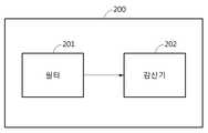
도 2는 일실시예에 따른 신호 필터링 장치의 구성의 일례이다.2 is an example of a configuration of a signal filtering apparatus according to an embodiment.
일실시예에 따르면, 신호 필터링 장치(200)는 필터(201) 및 감산기(202)를 포함한다. 필터(201)는 미리 정해진 통과대역을 갖고, 입력신호를 통과대역으로 필터링하여, 통과대역에 있는 불요신호를 출력한다.According to an embodiment, the
일실시예에 따르면, 감산기(202)는 필터(201)에 의해 출력되는 불요신호와 입력신호를 입력 받는다. 감산기(202)는 입력신호에서 불요신호를 제거(subtract)하여, 타겟신호를 출력한다. 여기서, 필터(201) 및 감산기(202)로 신호를 입력하고 출력하는 동작의 명령은 프로세서에 의해 제어된다.According to an exemplary embodiment, the
일실시예에 따르면, 입력신호는 원신호가 전처리된 것일 수 있고, 원신호는 생체신호를 포함할 수 있다. 생체신호는 ECG, PPG 및 EMG 등의 신호 중 어느 하나일 수 있다. 원신호에 대한 전처리는 DC 오프셋을 제거하는 동작을 포함한다.According to an embodiment, the input signal may be a pre-processed original signal, and the original signal may include a biosignal. The biosignal may be any one of signals such as ECG, PPG, and EMG. The pre-processing of the original signal includes the operation of removing the DC offset.
일실시예에 따르면, ECG, PPG 및 EMG 등의 원신호로부터 DC 오프셋이 추정되고, 추정된 DC 오프셋이 원신호로부터 제거되고, 원신호로부터 DC 오프셋이 제거된(전처리된) 입력신호가 필터(201)에 입력되고, 감산기(202)를 통해 타겟신호가 획득될 수 있다.According to an embodiment, a DC offset is estimated from an original signal such as ECG, PPG, and EMG, the estimated DC offset is removed from the original signal, and the input signal from which the DC offset is removed (pre-processed) from the original signal is filtered ( 201 , and a target signal may be obtained through the
도 3은 일실시예에 따른 신호 필터링 장치의 구성의 일례이다.3 is an example of a configuration of a signal filtering apparatus according to an embodiment.
일실시예에 따르면, 입력신호로부터 제거하고자 하는 신호의 대역이 추정된다. 여기서 추정된 신호의 대역을 통과대역으로 하는 필터(301)로 입력신호가 인가된다. 필터(301)는 입력신호로부터 통과대역에 있는 불요신호를 출력한다.According to an embodiment, the band of the signal to be removed from the input signal is estimated. Here, the input signal is applied to the
필터(301)를 통해 불요신호가 출력되는 동안에 신호의 지연현상(propagation delay)이 발생할 수 있다. 따라서, 입력신호로부터 불요신호를 빼주기 이전에, 해당 입력신호에 대해 필터(301)에 의해 지연된 시간만큼의 지연 보상이 수행된다. 지연 보상부(302)는 입력신호가 필터(301)를 통과하여 불요신호가 출력되는데 지연된 시간만큼 입력신호에 대한 시간 지연을 보상하고, 시간 지연된 입력신호를 가감산기(303)에 입력한다.A signal propagation delay may occur while the unwanted signal is output through the
가감산기(303)는 필터(301)로부터 출력된 불요신호와 지연 보상부(302)로부터 출력된 시간 지연된 입력신호를 이용하여, 시간 지연된 입력신호로부터 불요신호를 제거하고, 타겟 신호를 출력한다.The
도 4는 일실시예에 따른 입력신호, 불요신호 및 타겟신호의 일례이다.4 is an example of an input signal, an unwanted signal, and a target signal according to an embodiment.
일실시예에 따라서, 입력신호를 필터에 입력하고, 필터를 통해 불요신호가 출력되고, 입력신호로부터 불요신호가 제거되면, 각 신호들은 도 4와 같은 형태를 가질 수 있는데, 이는 타겟신호가 고주파수 대역의 신호인 실시예를 나타낸다. 이 때, 일실시예에 따른 신호 필터링 장치는 하이 패스 필터(High Pass Filter; HPF)로 대체될 수 있다. 만약, 타겟신호가 저주파수 대역의 신호인 경우에는, 일실시예에 따른 신호 필터링 장치는 로우 패스 필터(Low Pass Filter; LPF)로 대체될 수 있다. 이는 설계 방식에 따라 다양하게 응용될 수 있다.According to an exemplary embodiment, when an input signal is input to a filter, an unwanted signal is output through the filter, and the unwanted signal is removed from the input signal, each signal may have a shape as shown in FIG. 4 , which indicates that the target signal has a high frequency An embodiment in which a signal in a band is shown. In this case, the signal filtering apparatus according to an embodiment may be replaced with a high pass filter (HPF). If the target signal is a signal of a low frequency band, the signal filtering apparatus according to an exemplary embodiment may be replaced with a low pass filter (LPF). This can be applied in various ways depending on the design method.
일실시예에 따르면, 입력신호(401)로부터 컷 오프 주파수 미만의 미리 정해진 통과대역의 필터를 통해, 불요신호(402)가 추출된다. 추출된 불요신호(402)를 입력신호(401)에서 제거하여, 관심대역의 타겟신호(403)가 획득될 수 있다.According to an embodiment, the
일실시예에 따르면, 미리 정해진 통과대역의 필터를 통해 불요신호(402)를 추출할 때, IIR 필터가 이용된다면 낮은 계산 복잡도로 통과대역의 불요신호(402)의 추출이 가능하다.According to an embodiment, when extracting the
도 5는 일실시예에 따른 신호 처리 방법을 설명하는 순서도이다.5 is a flowchart illustrating a signal processing method according to an embodiment.
일실시예에 따르면, 원신호(raw signal)로부터 DC 오프셋(offset)이 추정된다(501). DC 오프셋이 큰 원신호가 필터에 입력되는 경우, 미리 정해진 통과대역을 갖는 필터로부터 출력되는 신호가 수렴하는 데 수초 이상의 정착 시간(settling time)이 필요하다.According to an embodiment, a DC offset is estimated from a raw signal (501). When an original signal having a large DC offset is input to the filter, a settling time of several seconds or more is required for the signal output from the filter having a predetermined passband to converge.
일실시예에 따르면, 원신호로부터 추정된 DC 오프셋이 제거된 입력신호가 생성될 수 있다(502). 원신호를 필터에 인가하기 전에, 원신호에서 DC 오프셋을 제거한 입력신호를 필터에 인가한다면, 필터에 의한 정착 시간이 줄어들 수 있다.According to an embodiment, an input signal from which the DC offset estimated from the original signal is removed may be generated ( 502 ). Before applying the original signal to the filter, if the input signal obtained by removing the DC offset from the original signal is applied to the filter, the settling time by the filter may be reduced.
일실시예에 따르면, 입력신호가 미리 정해진 통과대역을 갖는 필터에 입력되어, 통과대역의 불요신호가 제거된 타겟신호가 획득될 수 있다(503). 일실시예에 따르면, 미리 정해진 통과대역의 필터를 통해 입력된 입력신호로부터 불요신호가 획득되고, 입력신호와 불요신호가 감산기에 입력될 수 있다. 감산기에 의해 입력신호에서 불요신호가 제거된 타겟신호가 획득되는데, 감산기로 입력되는 입력신호는 불요신호를 획득하는데 소요된 시간 지연이 보상된 신호일 수 있다.According to an embodiment, an input signal is input to a filter having a predetermined passband, and a target signal from which an unnecessary signal of the passband is removed may be obtained ( S503 ). According to an embodiment, an unwanted signal may be obtained from an input signal input through a filter of a predetermined passband, and the input signal and the unwanted signal may be input to the subtractor. A target signal from which the spurious signal is removed from the input signal is obtained by the subtractor. The input signal input to the subtractor may be a signal in which a time delay required to obtain the spurious signal is compensated.
일실시예에 따르면, 추정된 DC 오프셋을 타겟신호에 대해 보상할지 여부에 대한 판단결과에 기초하여 타겟신호에 대해 DC 오프셋이 보상될 수 있다. 예를 들어, 타겟신호가 미리 정해진 주파수보다 저주파수인 경우, DC 오프셋을 보상하고, 타겟신호가 미리 정해진 주파수보다 고주파수인 경우, DC 오프셋을 보상하지 않도록 판단될 수 있다. 여기서, 입력신호로부터 불요신호를 제거하는 동작에 대해서는, 도 1 내지 도 4를 참조하여 설명된 실시예가 적용될 수 있지만, 이에 한정되지 않는다.According to an embodiment, the DC offset may be compensated for the target signal based on a result of determining whether to compensate the estimated DC offset for the target signal. For example, when the target signal has a lower frequency than a predetermined frequency, it may be determined that the DC offset is compensated, and when the target signal has a higher frequency than the predetermined frequency, it may be determined not to compensate the DC offset. Here, with respect to the operation of removing the unwanted signal from the input signal, the embodiments described with reference to FIGS. 1 to 4 may be applied, but the present invention is not limited thereto.
도 6은 일실시예에 따른 신호 처리 장치의 구성의 일례이다.6 is an example of a configuration of a signal processing apparatus according to an embodiment.
일실시예에 따르면, 신호 처리 장치(600)는 DC 오프셋 제거부(601), 필터부(602) 및 DC 오프셋 보상부(603)를 포함한다.According to an embodiment, the
일실시예에 따른 DC 오프셋 제거부(601)는 원신호로부터 DC 오프셋을 추정하고, 원신호로부터 DC 오프셋을 제거하여 입력신호를 출력한다. DC 오프셋을 추정하는 동작은 미리 알고 있는 정보에 대한 조회일 수 있고, 원신호로부터 DC 오프셋의 값을 추정하는 것일 수 있다.The DC offset removing
일실시예에 따른 필터부(602)는 입력신호에서 미리 정해진 통과대역의 불요신호를 제거하여, 타겟신호를 출력한다. 도 6에는 도시하지 않았지만, 필터부(602)는 미리 정해진 통과대역을 갖는 필터와 감산기를 포함할 수 있다. 필터부(602)의 필터는 인가된 입력신호에 대해 통과대역의 불요신호를 추출하고, 추출된 불요신호를 출력할 수 있다. 필터부(602)의 감산기는 불요신호와 입력신호를 입력 받고, 입력신호로부터 불요신호를 제거하여 타겟신호를 출력할 수 있다. 이 때, 감산기에 입력되는 입력신호는 필터부(602)를 경유하는데 소요된 시간만큼 시간 지연이 보상된 것일 수 있다.The
일실시예에 따른 DC 오프셋 보상부(603)는 타겟신호에 대해 DC 오프셋을 보상할지 여부를 판단하고, 판단결과에 따라 DC 오프셋을 보상한다. DC 오프셋 보상부(603)는 타겟신호가 미리 정해진 주파수보다 저주파수인 경우, DC 오프셋을 보상하고, 타겟신호가 미리 정해진 주파수보다 고주파수인 경우, DC 오프셋을 보상하지 않을 수 있다.The DC offset
도 7은 일실시예에 따른 신호 처리 장치의 구성의 일례이다.7 is an example of the configuration of a signal processing apparatus according to an embodiment.
도 7을 참조하면, DC 오프셋 추정부(701)는 원신호를 입력 받아서, 원신호로부터 DC 오프셋을 추정하고, 추정된 DC 오프셋을 출력하고, 출력된 DC 오프셋을 가감산기(702)로 입력한다. 가감산기(702)는 원신호와 DC 오프셋을 입력 받고, 원신호로부터 DC 오프셋을 제거하여 출력하는데, 여기서 출력된 신호를 입력신호라 한다.Referring to FIG. 7 , the DC offset
필터부(703)는 가감산기(702)로부터 출력된 입력신호에서 미리 정해진 통과대역의 불요신호를 추출하고, 입력신호에서 불요신호를 제거한 타겟신호를 출력한다. 필터부(703)는 출력된 타겟신호를 가감산기(705)로 입력한다.The
DC 오프셋 보상 판단부(704)는 추정된 DC 오프셋과 원신호에 대한 정보를 DC 오프셋 추정부(701)로부터 입력 받아, 타겟신호에 대한 DC 오프셋의 보상이 필요한지 여부를 판단한다. DC 오프셋 보상 판단부(704)는 타겟신호가 미리 정해진 주파수보다 큰 고주파수 대역의 신호인 경우에는 DC 오프셋의 보상이 필요하므로, DC 오프셋을 가감산기(705)로 입력한다. 만약, 타겟신호가 미리 정해진 주파수보다 작은 저주파수 대역의 신호인 경우에는, DC 오프셋의 보상이 필요하지 않으므로, DC 오프셋 보상 판단부(704)는 DC 오프셋을 가감산기(705)로 입력하지 않는다.The DC offset
가감산기(705)는 필터부(703)로부터 출력된 타겟신호와 DC 오프셋 보상 판단부(704)로부터 출력된 DC 오프셋을 이용하여, DC 오프셋이 보상된 타겟신호를 출력한다.The adder/
도 8은 일실시예에 따른 신호 처리 장치의 구성의 일례이다.8 is an example of the configuration of a signal processing apparatus according to an embodiment.
도 8을 참조하면, DC 오프셋 제거부(801)는 원신호를 입력 받아서, 원신호로부터 추정되는 DC 오프셋을 원신호에서 제거하여, 입력신호를 출력한다. DC 오프셋 제거부(801)는 입력신호를 필터(802) 및 지연 보상부(803)로 입력한다.Referring to FIG. 8 , the DC offset removing
필터(802)는 미리 정해진 통과대역을 갖는다. 필터(802)는 DC 오프셋 제거부(801)로부터 출력된 입력신호에 대한 통과대역의 불요신호를 출력한다.The
지연 보상부(803)는 DC 오프셋 제거부(801)로부터 출력된 입력신호에 대해 시간 지연을 수행한다. 지연 보상부(803)는 필터(802)를 통해 불요신호가 추출되는데 소요되는 지연 시간을 입력신호에 대해 보상한다. 지연 보상부(803)는 지연 시간이 보상된 입력신호를 출력한다.The
가감산기(804)는 지연 보상부(803)로부터 출력되는 지연 시간이 보상된 입력신호에서 필터(802)로부터 출력되는 불요신호를 제거하여 타겟신호를 출력한다.The
DC 오프셋 보상 판단부(805)는 DC 오프셋 제거부(801)로부터 추정된 DC 오프셋과 원신호에 대한 정보를 입력 받아서, 타겟신호에 대한 DC 오프셋의 보상이 필요한지 여부를 판단하고, 판단결과에 기초하여 보상이 필요한 DC 오프셋을 출력한다. 가감산기(806)는 타겟신호와 DC 오프셋 보상 판단부(805)로부터 출력되는 DC 오프셋을 입력 받고, 타겟신호에 대한 DC 오프셋을 보상하여, DC 오프셋이 보상된 타겟신호를 출력한다.The DC offset
이상에서 설명된 실시예들은 하드웨어 구성요소, 소프트웨어 구성요소, 및/또는 하드웨어 구성요소 및 소프트웨어 구성요소의 조합으로 구현될 수 있다. 예를 들어, 실시예들에서 설명된 장치, 방법 및 구성요소는, 예를 들어, 프로세서, 콘트롤러, ALU(arithmetic logic unit), 디지털 신호 프로세서(digital signal processor), 마이크로컴퓨터, FPGA(field programmable gate array), PLU(programmable logic unit), 마이크로프로세서, 또는 명령(instruction)을 실행하고 응답할 수 있는 다른 어떠한 장치와 같이, 하나 이상의 범용 컴퓨터 또는 특수 목적 컴퓨터를 이용하여 구현될 수 있다. 처리 장치는 운영 체제(OS) 및 상기 운영 체제 상에서 수행되는 하나 이상의 소프트웨어 애플리케이션을 수행할 수 있다. 또한, 처리 장치는 소프트웨어의 실행에 응답하여, 데이터를 접근, 저장, 조작, 처리 및 생성할 수도 있다. 이해의 편의를 위하여, 처리 장치는 하나가 사용되는 것으로 설명된 경우도 있지만, 해당 기술분야에서 통상의 지식을 가진 자는, 처리 장치가 복수 개의 처리 요소(processing element) 및/또는 복수 유형의 처리 요소를 포함할 수 있음을 알 수 있다. 예를 들어, 처리 장치는 복수 개의 프로세서 또는 하나의 프로세서 및 하나의 콘트롤러를 포함할 수 있다. 또한, 병렬 프로세서(parallel processor)와 같은, 다른 처리 구성(processing configuration)도 가능하다.The embodiments described above may be implemented by a hardware component, a software component, and/or a combination of a hardware component and a software component. For example, the apparatus, methods and components described in the embodiments may include, for example, a processor, a controller, an arithmetic logic unit (ALU), a digital signal processor, a microcomputer, a field programmable gate (FPGA). array), a programmable logic unit (PLU), a microprocessor, or any other device capable of executing and responding to instructions, may be implemented using one or more general purpose or special purpose computers. The processing device may execute an operating system (OS) and one or more software applications running on the operating system. The processing device may also access, store, manipulate, process, and generate data in response to execution of the software. For convenience of understanding, although one processing device is sometimes described as being used, one of ordinary skill in the art will recognize that the processing device includes a plurality of processing elements and/or a plurality of types of processing elements. It can be seen that may include For example, the processing device may include a plurality of processors or one processor and one controller. Other processing configurations are also possible, such as parallel processors.
소프트웨어는 컴퓨터 프로그램(computer program), 코드(code), 명령(instruction), 또는 이들 중 하나 이상의 조합을 포함할 수 있으며, 원하는 대로 동작하도록 처리 장치를 구성하거나 독립적으로 또는 결합적으로(collectively) 처리 장치를 명령할 수 있다. 소프트웨어 및/또는 데이터는, 처리 장치에 의하여 해석되거나 처리 장치에 명령 또는 데이터를 제공하기 위하여, 어떤 유형의 기계, 구성요소(component), 물리적 장치, 가상 장치(virtual equipment), 컴퓨터 저장 매체 또는 장치, 또는 전송되는 신호 파(signal wave)에 영구적으로, 또는 일시적으로 구체화(embody)될 수 있다. 소프트웨어는 네트워크로 연결된 컴퓨터 시스템 상에 분산되어서, 분산된 방법으로 저장되거나 실행될 수도 있다. 소프트웨어 및 데이터는 하나 이상의 컴퓨터 판독 가능 기록 매체에 저장될 수 있다.The software may comprise a computer program, code, instructions, or a combination of one or more thereof, which configures a processing device to operate as desired or is independently or collectively processed You can command the device. The software and/or data may be any kind of machine, component, physical device, virtual equipment, computer storage medium or device, to be interpreted by or to provide instructions or data to the processing device. , or may be permanently or temporarily embody in a transmitted signal wave. The software may be distributed over networked computer systems and stored or executed in a distributed manner. Software and data may be stored in one or more computer-readable recording media.
실시예에 따른 방법은 다양한 컴퓨터 수단을 통하여 수행될 수 있는 프로그램 명령 형태로 구현되어 컴퓨터 판독 가능 매체에 기록될 수 있다. 상기 컴퓨터 판독 가능 매체는 프로그램 명령, 데이터 파일, 데이터 구조 등을 단독으로 또는 조합하여 포함할 수 있다. 상기 매체에 기록되는 프로그램 명령은 실시예를 위하여 특별히 설계되고 구성된 것들이거나 컴퓨터 소프트웨어 당업자에게 공지되어 사용 가능한 것일 수도 있다. 컴퓨터 판독 가능 기록 매체의 예에는 하드 디스크, 플로피 디스크 및 자기 테이프와 같은 자기 매체(magnetic media), CD-ROM, DVD와 같은 광기록 매체(optical media), 플롭티컬 디스크(floptical disk)와 같은 자기-광 매체(magneto-optical media), 및 롬(ROM), 램(RAM), 플래시 메모리 등과 같은 프로그램 명령을 저장하고 수행하도록 특별히 구성된 하드웨어 장치가 포함된다. 프로그램 명령의 예에는 컴파일러에 의해 만들어지는 것과 같은 기계어 코드뿐만 아니라 인터프리터 등을 사용해서 컴퓨터에 의해서 실행될 수 있는 고급 언어 코드를 포함한다. 상기된 하드웨어 장치는 실시예의 동작을 수행하기 위해 하나 이상의 소프트웨어 모듈로서 작동하도록 구성될 수 있으며, 그 역도 마찬가지이다.The method according to the embodiment may be implemented in the form of program instructions that can be executed through various computer means and recorded in a computer-readable medium. The computer-readable medium may include program instructions, data files, data structures, etc. alone or in combination. The program instructions recorded on the medium may be specially designed and configured for the embodiment, or may be known and available to those skilled in the art of computer software. Examples of the computer-readable recording medium include magnetic media such as hard disks, floppy disks and magnetic tapes, optical media such as CD-ROMs and DVDs, and magnetic such as floppy disks. - includes magneto-optical media, and hardware devices specially configured to store and execute program instructions, such as ROM, RAM, flash memory, and the like. Examples of program instructions include not only machine language codes such as those generated by a compiler, but also high-level language codes that can be executed by a computer using an interpreter or the like. The hardware devices described above may be configured to operate as one or more software modules to perform the operations of the embodiments, and vice versa.
이상과 같이 실시예들이 비록 한정된 도면에 의해 설명되었으나, 해당 기술분야에서 통상의 지식을 가진 자라면 상기를 기초로 다양한 기술적 수정 및 변형을 적용할 수 있다. 예를 들어, 설명된 기술들이 설명된 방법과 다른 순서로 수행되거나, 및/또는 설명된 시스템, 구조, 장치, 회로 등의 구성요소들이 설명된 방법과 다른 형태로 결합 또는 조합되거나, 다른 구성요소 또는 균등물에 의하여 대치되거나 치환되더라도 적절한 결과가 달성될 수 있다.As described above, although the embodiments have been described with reference to the limited drawings, those skilled in the art may apply various technical modifications and variations based on the above. For example, the described techniques are performed in a different order than the described method, and/or the described components of the system, structure, apparatus, circuit, etc. are combined or combined in a different form than the described method, or other components Or substituted or substituted by equivalents may achieve an appropriate result.
그러므로, 다른 구현들, 다른 실시예들 및 특허청구범위와 균등한 것들도 후술하는 특허청구범위의 범위에 속한다.Therefore, other implementations, other embodiments, and equivalents to the claims are also within the scope of the following claims.
Claims (20)
Translated fromKorean상기 필터를 통해 상기 통과대역의 불요신호(unnecessary signal)를 획득하는 단계;
상기 입력신호와 상기 불요신호를 감산기로 입력하여 상기 입력신호에서 상기 불요신호가 제거된 타겟신호를 획득하는 단계; 및
상기 타겟신호의 주파수와 임계(threshold) 주파수의 비교에 기초하여, 상기 타겟신호에 대해 추정된 DC 오프셋(offset)을 보상할지 여부를 판단하는 단계
를 포함하는,
신호 처리 방법.
inputting an input signal to a filter having a predetermined passband;
obtaining an unnecessary signal of the passband through the filter;
obtaining a target signal from which the unwanted signal is removed from the input signal by inputting the input signal and the unwanted signal to a subtractor; and
determining whether to compensate an estimated DC offset with respect to the target signal based on a comparison of the frequency of the target signal and a threshold frequency;
containing,
signal processing method.
상기 필터는 저주파수 대역 통과 필터인,
신호 처리 방법.
According to claim 1,
The filter is a low frequency band pass filter,
signal processing method.
상기 필터는 무한임펄스응답(Infinite Impulse Response; IIR) 필터인,
신호 처리 방법.
3. The method of claim 2,
The filter is an Infinite Impulse Response (IIR) filter,
signal processing method.
상기 감산기로 입력되는 상기 입력신호는,
상기 불요신호를 획득하는데 소요된 시간 지연이 보상된 신호인,
신호 처리 방법.
According to claim 1,
The input signal input to the subtractor is
A signal in which the time delay required to obtain the spurious signal is compensated,
signal processing method.
상기 입력신호는,
원신호(raw signal)에서 상기 추정된 DC 오프셋(offset)이 제거된 신호인,
신호 처리 방법.
According to claim 1,
The input signal is
A signal in which the estimated DC offset is removed from the raw signal,
signal processing method.
상기 DC 오프셋을 보상할지 여부를 판단하는 단계는,
상기 타겟신호가 임계 주파수보다 낮은 경우, 상기 DC 오프셋을 보상하고, 상기 타겟신호가 상기 임계 주파수보다 높은 경우, 상기 DC 오프셋을 보상하지 않도록 판단하는 단계
를 포함하는,
신호 처리 방법.
According to claim 1,
The step of determining whether to compensate the DC offset comprises:
Compensating the DC offset when the target signal is lower than the threshold frequency, and determining not to compensate the DC offset when the target signal is higher than the threshold frequency
containing,
signal processing method.
입력신호를 상기 필터에 인가하여 획득된 상기 통과대역의 불요신호와 상기 입력신호가 입력되고, 상기 입력신호에서 상기 불요신호가 제거된 타겟신호를 출력하는 감산기; 및
상기 타겟신호의 주파수와 임계(threshold) 주파수의 비교에 기초하여, 상기 타겟신호에 대해 추정된 DC 오프셋(offset)을 보상할지 여부를 판단하는 보상 판단기
를 포함하는
신호 필터링 장치.
a filter having a predetermined passband;
a subtractor for outputting a target signal from which the unwanted signal of the passband obtained by applying an input signal to the filter and the input signal are input, and the unnecessary signal is removed from the input signal; and
A compensation determiner that determines whether to compensate the DC offset estimated with respect to the target signal based on the comparison of the frequency of the target signal with a threshold frequency
containing
signal filtering device.
상기 입력신호는 생체신호인,
신호 필터링 장치.
9. The method of claim 8,
The input signal is a biological signal,
signal filtering device.
상기 불요신호는 DC 성분 및 미리 정해진 컷오프 주파수 미만의 저주파수 대역 신호인,
신호 필터링 장치.
9. The method of claim 8,
The spurious signal is a DC component and a low frequency band signal below a predetermined cutoff frequency,
signal filtering device.
상기 원신호로부터 상기 DC 오프셋을 제거하여 입력신호를 생성하는 단계;
상기 입력신호를 미리 정해진 통과대역을 갖는 필터에 입력하여 상기 통과대역의 불요신호(unnecessary signal)가 제거된 타겟신호를 획득하는 단계
상기 타겟신호가 임계 주파수보다 낮은 주파수인 경우, 상기 DC 오프셋을 보상하고, 상기 타겟신호가 상기 임계 주파수보다 높은 주파수인 경우, 상기 DC 오프셋을 보상하지 않도록 판단하는 단계
를 포함하는,
신호 처리 방법.
estimating a DC offset from a raw signal;
generating an input signal by removing the DC offset from the original signal;
inputting the input signal to a filter having a predetermined passband to obtain a target signal from which an unnecessary signal of the passband is removed
Compensating for the DC offset when the target signal has a frequency lower than the threshold frequency, and determining not to compensate the DC offset when the target signal has a frequency higher than the threshold frequency
containing,
signal processing method.
상기 타겟신호를 획득하는 단계는,
상기 필터를 통해 상기 불요신호를 획득하는 단계; 및
상기 입력신호와 상기 불요신호를 감산기로 입력하여, 상기 입력신호에서 상기 불요신호가 제거된 상기 타겟신호를 획득하는 단계
를 포함하는,
신호 처리 방법.
13. The method of claim 12,
The step of obtaining the target signal comprises:
obtaining the spurious signal through the filter; and
inputting the input signal and the spurious signal to a subtractor to obtain the target signal from which the spurious signal is removed from the input signal;
containing,
signal processing method.
상기 감산기로 입력되는 상기 입력신호는,
상기 불요신호를 획득하는데 소요된 시간 지연이 보상된 신호인,
신호 처리 방법.
14. The method of claim 13,
The input signal input to the subtractor is
A signal in which the time delay required to obtain the spurious signal is compensated,
signal processing method.
상기 타겟신호에 대해 상기 DC 오프셋을 보상할지 여부를 판단하는 단계; 및
상기 판단결과에 기초하여, 상기 타겟신호에 대해 상기 DC 오프셋을 보상하는 단계
를 더 포함하는,
신호 처리 방법.
13. The method of claim 12,
determining whether to compensate the DC offset for the target signal; and
Compensating for the DC offset with respect to the target signal based on the determination result
further comprising,
signal processing method.
상기 입력신호에서 미리 정해진 통과대역의 불요신호를 제거하여, 타겟신호를 출력하는 필터부; 및
상기 타겟신호가 임계 주파수보다 낮은 주파수인 경우, 상기 DC 오프셋을 보상하고, 상기 타겟신호가 상기 임계 주파수보다 높은 주파수인 경우, 상기 DC 오프셋을 보상하지 않는 보상부
를 포함하는신호 처리 장치.
a DC offset removing unit for estimating a DC offset from a raw signal and outputting an input signal by removing the DC offset from the original signal;
a filter unit for outputting a target signal by removing an unnecessary signal of a predetermined pass band from the input signal; and
When the target signal has a frequency lower than the threshold frequency, the DC offset is compensated, and when the target signal is a frequency higher than the threshold frequency, the compensator does not compensate for the DC offset.
A signal processing device comprising a.
상기 타겟신호에 대해 상기 DC 오프셋을 보상할지 여부를 판단하고, 상기 판단결과에 따라 상기 DC 오프셋을 보상하는 DC 오프셋 보상부
를 더 포함하는,
신호 처리 장치.
18. The method of claim 17,
A DC offset compensator for determining whether to compensate the DC offset for the target signal and compensating for the DC offset according to the determination result
further comprising,
signal processing unit.
상기 필터부는,
상기 통과대역을 갖는 필터; 및
상기 입력신호를 상기 필터에 인가하여 획득된 상기 불요신호와 상기 입력신호가 입력되고, 상기 입력신호에서 상기 불요신호가 제거된 상기 타겟신호를 출력하는 감산기
를 포함하는,
신호 처리 장치.18. The method of claim 17,
The filter unit,
a filter having the passband; and
The spurious signal obtained by applying the input signal to the filter and the input signal are input, and the subtractor outputs the target signal from which the spurious signal is removed.
containing,
signal processing unit.
Priority Applications (5)
| Application Number | Priority Date | Filing Date | Title |
|---|---|---|---|
| KR1020150174790AKR102451268B1 (en) | 2015-12-09 | 2015-12-09 | Signal processing method, signal filtering apparatus and signal processing unit |
| US15/349,230US10382074B2 (en) | 2015-12-09 | 2016-11-11 | Signal filtering and signal processing apparatus and method |
| US16/512,890US10530404B2 (en) | 2015-12-09 | 2019-07-16 | Signal filtering and signal processing apparatus and method |
| US16/733,617US10826544B2 (en) | 2015-12-09 | 2020-01-03 | Signal filtering and signal processing apparatus and method |
| KR1020220124567AKR102688647B1 (en) | 2015-12-09 | 2022-09-29 | Signal processing method, signal filtering apparatus and signal processing unit |
Applications Claiming Priority (1)
| Application Number | Priority Date | Filing Date | Title |
|---|---|---|---|
| KR1020150174790AKR102451268B1 (en) | 2015-12-09 | 2015-12-09 | Signal processing method, signal filtering apparatus and signal processing unit |
Related Child Applications (1)
| Application Number | Title | Priority Date | Filing Date |
|---|---|---|---|
| KR1020220124567ADivisionKR102688647B1 (en) | 2015-12-09 | 2022-09-29 | Signal processing method, signal filtering apparatus and signal processing unit |
Publications (2)
| Publication Number | Publication Date |
|---|---|
| KR20170068055A KR20170068055A (en) | 2017-06-19 |
| KR102451268B1true KR102451268B1 (en) | 2022-10-06 |
Family
ID=59020988
Family Applications (2)
| Application Number | Title | Priority Date | Filing Date |
|---|---|---|---|
| KR1020150174790AActiveKR102451268B1 (en) | 2015-12-09 | 2015-12-09 | Signal processing method, signal filtering apparatus and signal processing unit |
| KR1020220124567AActiveKR102688647B1 (en) | 2015-12-09 | 2022-09-29 | Signal processing method, signal filtering apparatus and signal processing unit |
Family Applications After (1)
| Application Number | Title | Priority Date | Filing Date |
|---|---|---|---|
| KR1020220124567AActiveKR102688647B1 (en) | 2015-12-09 | 2022-09-29 | Signal processing method, signal filtering apparatus and signal processing unit |
Country Status (2)
| Country | Link |
|---|---|
| US (3) | US10382074B2 (en) |
| KR (2) | KR102451268B1 (en) |
Families Citing this family (2)
| Publication number | Priority date | Publication date | Assignee | Title |
|---|---|---|---|---|
| US10898144B2 (en)* | 2016-11-22 | 2021-01-26 | Microsoft Technology Licensing, Llc | Photoplethysmography (PPG) indication discontinuity detection and correction |
| CN117879538A (en)* | 2023-12-21 | 2024-04-12 | 人工智能与数字经济广东省实验室(深圳) | A delay compensation filtering method and related equipment for suppressing high frequency measurement noise |
Citations (2)
| Publication number | Priority date | Publication date | Assignee | Title |
|---|---|---|---|---|
| US20060020218A1 (en)* | 2004-02-26 | 2006-01-26 | Warwick Freeman | Method and apparatus for continuous electrode impedance monitoring |
| US20120116198A1 (en)* | 2009-07-13 | 2012-05-10 | Koninklijke Philips Electronics N.V. | Electro-physiological measurement with reduced motion artifacts |
Family Cites Families (21)
| Publication number | Priority date | Publication date | Assignee | Title |
|---|---|---|---|---|
| US5269313A (en)* | 1991-09-09 | 1993-12-14 | Sherwood Medical Company | Filter and method for filtering baseline wander |
| KR100400213B1 (en) | 1997-05-08 | 2003-11-14 | 삼성전자주식회사 | Apparatus for eliminating baseline wander of electrocardiogram signal |
| KR20060119472A (en) | 2005-05-20 | 2006-11-24 | 건양대학교산학협력단 | How to eliminate baseline fluctuations in ECG signals |
| KR100857179B1 (en)* | 2006-12-26 | 2008-09-05 | 삼성전자주식회사 | Biosignal amplification circuit |
| KR100866547B1 (en) | 2007-02-09 | 2008-11-03 | 연세대학교 산학협력단 | Electroencephalogram test device and method with electrocardiogram noise removing means |
| EP2143391B1 (en)* | 2008-07-07 | 2011-06-08 | BrainLAB AG | Device for positioning or attaching a medical operating instrument, especially an incision block or a cutting block |
| TWI481196B (en)* | 2008-12-31 | 2015-04-11 | Ind Tech Res Inst | Bioelectricity signal sensing apparatus and device for canceling baseline drift in bioelectricity signal |
| US8620978B2 (en)* | 2008-12-31 | 2013-12-31 | St. Jude Medical, Atrial Fibrillation Division, Inc. | System and method for filtering electrophysiological signals |
| KR100995318B1 (en)* | 2009-03-27 | 2010-11-19 | 서울과학기술대학교 산학협력단 | Signal detection device and method |
| US8718980B2 (en)* | 2009-09-11 | 2014-05-06 | Qualcomm Incorporated | Method and apparatus for artifacts mitigation with multiple wireless sensors |
| KR101276973B1 (en) | 2009-12-14 | 2013-06-19 | 연세대학교 원주산학협력단 | Pulse frequency measurement method and apparatus |
| KR101736978B1 (en) | 2010-06-10 | 2017-05-17 | 삼성전자주식회사 | Apparatus and method for measuring biological signal |
| KR20120089780A (en) | 2010-11-17 | 2012-08-13 | 경북대학교 산학협력단 | Bio-signal estimating apparatus and bio-signal estimating method thereof |
| US20120265080A1 (en)* | 2011-04-15 | 2012-10-18 | Xiong Yu | Non-contact sensing of physiological signals |
| JP5919722B2 (en) | 2011-10-18 | 2016-05-18 | 株式会社豊田中央研究所 | Biological signal estimation apparatus and program |
| WO2013106559A2 (en)* | 2012-01-10 | 2013-07-18 | The Regents Of The University Of Michigan | Atrial fibrillation classification using power measurement |
| KR101947676B1 (en) | 2012-10-29 | 2019-02-13 | 삼성전자주식회사 | Method and apparatus for measuring bio signal |
| US9351653B1 (en)* | 2012-11-29 | 2016-05-31 | Intan Technologies, LLC | Multi-channel reconfigurable systems and methods for sensing biopotential signals |
| KR101833254B1 (en) | 2013-06-20 | 2018-02-28 | 광주과학기술원 | Device for processing bio-signal |
| KR101517988B1 (en) | 2013-07-24 | 2015-05-06 | 광운대학교 산학협력단 | Electrocardiography detection method and apparatus |
| KR101539923B1 (en) | 2013-12-27 | 2015-07-29 | 가톨릭대학교 산학협력단 | Bio-Signal Based Eye-Tracking System Using Dual Machine Learning Structure and Eye-Tracking Method using The Same |
- 2015
- 2015-12-09KRKR1020150174790Apatent/KR102451268B1/enactiveActive
- 2016
- 2016-11-11USUS15/349,230patent/US10382074B2/enactiveActive
- 2019
- 2019-07-16USUS16/512,890patent/US10530404B2/enactiveActive
- 2020
- 2020-01-03USUS16/733,617patent/US10826544B2/enactiveActive
- 2022
- 2022-09-29KRKR1020220124567Apatent/KR102688647B1/enactiveActive
Patent Citations (2)
| Publication number | Priority date | Publication date | Assignee | Title |
|---|---|---|---|---|
| US20060020218A1 (en)* | 2004-02-26 | 2006-01-26 | Warwick Freeman | Method and apparatus for continuous electrode impedance monitoring |
| US20120116198A1 (en)* | 2009-07-13 | 2012-05-10 | Koninklijke Philips Electronics N.V. | Electro-physiological measurement with reduced motion artifacts |
Also Published As
| Publication number | Publication date |
|---|---|
| US10826544B2 (en) | 2020-11-03 |
| US20190341949A1 (en) | 2019-11-07 |
| US10530404B2 (en) | 2020-01-07 |
| US20200145034A1 (en) | 2020-05-07 |
| KR102688647B1 (en) | 2024-07-25 |
| KR20170068055A (en) | 2017-06-19 |
| US20170170852A1 (en) | 2017-06-15 |
| US10382074B2 (en) | 2019-08-13 |
| KR20220137856A (en) | 2022-10-12 |
Similar Documents
| Publication | Publication Date | Title |
|---|---|---|
| AU2016201690B2 (en) | Method and system for noise cleaning of photoplethysmogram signals | |
| JP6608824B2 (en) | System and method for determining sleep stage based on sleep cycle | |
| Keshtkaran et al. | A fast, robust algorithm for power line interference cancellation in neural recording | |
| KR102688647B1 (en) | Signal processing method, signal filtering apparatus and signal processing unit | |
| Luo et al. | A hierarchical method for removal of baseline drift from biomedical signals: application in ECG analysis | |
| CN107949321A (en) | Temporal Interference Removal and Improved Heart Rate Measurement Tracking Mechanism | |
| Agarwal et al. | Performance evaluation and implementation of FPGA based SGSF in smart diagnostic applications | |
| CN106681961B (en) | Signal feature extraction method and device | |
| CN105705079A (en) | Device, method and system for processing a physiological signal | |
| WO2015107268A1 (en) | Method and device for the detection of respiratory rate | |
| TWI519276B (en) | Electrocardiography signal extraction method | |
| US20180070887A1 (en) | Blood pressure measuring device and blood pressure measuring method using the same | |
| CN107708531A (en) | The method that physiological parameter is determined from physiological data | |
| Satheeskumaran et al. | A new LMS based noise removal and DWT based R-peak detection in ECG signal for biotelemetry applications | |
| Pangerc et al. | Robust detection of heart beats in multimodal records using slope-and peak-sensitive band-pass filters | |
| CN108992054A (en) | A kind of pulse signal peak point detection method and device | |
| CN106725415A (en) | Method and device for processing electrophysiological signals | |
| Kim et al. | Semi-real-time removal of baseline fluctuations in electrocardiogram (ECG) signals by an infinite impulse response low-pass filter (IIR-LPF) | |
| CN110169766A (en) | A kind of cardiogram wave detection method, apparatus based on wavelet transformation, terminal device | |
| WO2016176067A1 (en) | Time-domain interference removal and improved tracking mechanism for heart rate measurements | |
| JP7457102B2 (en) | System that processes respiratory rate | |
| CN107405086B (en) | Measurement device, measurement method, and program | |
| Amhia et al. | Stability and Phase Response Analysis of Optimum Reduced‐Order IIR Filter Designs for ECG R‐Peak Detection | |
| Pin et al. | Circuit architectures reviews for portable ECG signal analyzer | |
| Terada et al. | Wavelet integrated convolutional neural network for ECG signal denoising |
Legal Events
| Date | Code | Title | Description |
|---|---|---|---|
| PA0109 | Patent application | St.27 status event code:A-0-1-A10-A12-nap-PA0109 | |
| PG1501 | Laying open of application | St.27 status event code:A-1-1-Q10-Q12-nap-PG1501 | |
| P22-X000 | Classification modified | St.27 status event code:A-2-2-P10-P22-nap-X000 | |
| A201 | Request for examination | ||
| PA0201 | Request for examination | St.27 status event code:A-1-2-D10-D11-exm-PA0201 | |
| E902 | Notification of reason for refusal | ||
| PE0902 | Notice of grounds for rejection | St.27 status event code:A-1-2-D10-D21-exm-PE0902 | |
| E13-X000 | Pre-grant limitation requested | St.27 status event code:A-2-3-E10-E13-lim-X000 | |
| P11-X000 | Amendment of application requested | St.27 status event code:A-2-2-P10-P11-nap-X000 | |
| P13-X000 | Application amended | St.27 status event code:A-2-2-P10-P13-nap-X000 | |
| E701 | Decision to grant or registration of patent right | ||
| PE0701 | Decision of registration | St.27 status event code:A-1-2-D10-D22-exm-PE0701 | |
| A107 | Divisional application of patent | ||
| PA0107 | Divisional application | St.27 status event code:A-0-1-A10-A18-div-PA0107 St.27 status event code:A-0-1-A10-A17-div-PA0107 St.27 status event code:A-0-1-A10-A16-div-PA0107 | |
| PR0701 | Registration of establishment | St.27 status event code:A-2-4-F10-F11-exm-PR0701 | |
| PR1002 | Payment of registration fee | St.27 status event code:A-2-2-U10-U11-oth-PR1002 Fee payment year number:1 | |
| PG1601 | Publication of registration | St.27 status event code:A-4-4-Q10-Q13-nap-PG1601 | |
| PR1001 | Payment of annual fee | St.27 status event code:A-4-4-U10-U11-oth-PR1001 Fee payment year number:4 |