KR102450901B1 - Molecular beam epitaxy apparatus - Google Patents
Molecular beam epitaxy apparatusDownload PDFInfo
- Publication number
- KR102450901B1 KR102450901B1KR1020210008548AKR20210008548AKR102450901B1KR 102450901 B1KR102450901 B1KR 102450901B1KR 1020210008548 AKR1020210008548 AKR 1020210008548AKR 20210008548 AKR20210008548 AKR 20210008548AKR 102450901 B1KR102450901 B1KR 102450901B1
- Authority
- KR
- South Korea
- Prior art keywords
- substrate
- thin film
- chamber
- molecular beam
- growth
- Prior art date
- Legal status (The legal status is an assumption and is not a legal conclusion. Google has not performed a legal analysis and makes no representation as to the accuracy of the status listed.)
- Active
Links
Images


Classifications
- C—CHEMISTRY; METALLURGY
- C23—COATING METALLIC MATERIAL; COATING MATERIAL WITH METALLIC MATERIAL; CHEMICAL SURFACE TREATMENT; DIFFUSION TREATMENT OF METALLIC MATERIAL; COATING BY VACUUM EVAPORATION, BY SPUTTERING, BY ION IMPLANTATION OR BY CHEMICAL VAPOUR DEPOSITION, IN GENERAL; INHIBITING CORROSION OF METALLIC MATERIAL OR INCRUSTATION IN GENERAL
- C23C—COATING METALLIC MATERIAL; COATING MATERIAL WITH METALLIC MATERIAL; SURFACE TREATMENT OF METALLIC MATERIAL BY DIFFUSION INTO THE SURFACE, BY CHEMICAL CONVERSION OR SUBSTITUTION; COATING BY VACUUM EVAPORATION, BY SPUTTERING, BY ION IMPLANTATION OR BY CHEMICAL VAPOUR DEPOSITION, IN GENERAL
- C23C14/00—Coating by vacuum evaporation, by sputtering or by ion implantation of the coating forming material
- C23C14/22—Coating by vacuum evaporation, by sputtering or by ion implantation of the coating forming material characterised by the process of coating
- C23C14/56—Apparatus specially adapted for continuous coating; Arrangements for maintaining the vacuum, e.g. vacuum locks
- C23C14/564—Means for minimising impurities in the coating chamber such as dust, moisture, residual gases
- C23C14/566—Means for minimising impurities in the coating chamber such as dust, moisture, residual gases using a load-lock chamber
- C—CHEMISTRY; METALLURGY
- C30—CRYSTAL GROWTH
- C30B—SINGLE-CRYSTAL GROWTH; UNIDIRECTIONAL SOLIDIFICATION OF EUTECTIC MATERIAL OR UNIDIRECTIONAL DEMIXING OF EUTECTOID MATERIAL; REFINING BY ZONE-MELTING OF MATERIAL; PRODUCTION OF A HOMOGENEOUS POLYCRYSTALLINE MATERIAL WITH DEFINED STRUCTURE; SINGLE CRYSTALS OR HOMOGENEOUS POLYCRYSTALLINE MATERIAL WITH DEFINED STRUCTURE; AFTER-TREATMENT OF SINGLE CRYSTALS OR A HOMOGENEOUS POLYCRYSTALLINE MATERIAL WITH DEFINED STRUCTURE; APPARATUS THEREFOR
- C30B23/00—Single-crystal growth by condensing evaporated or sublimed materials
- C30B23/02—Epitaxial-layer growth
- C—CHEMISTRY; METALLURGY
- C23—COATING METALLIC MATERIAL; COATING MATERIAL WITH METALLIC MATERIAL; CHEMICAL SURFACE TREATMENT; DIFFUSION TREATMENT OF METALLIC MATERIAL; COATING BY VACUUM EVAPORATION, BY SPUTTERING, BY ION IMPLANTATION OR BY CHEMICAL VAPOUR DEPOSITION, IN GENERAL; INHIBITING CORROSION OF METALLIC MATERIAL OR INCRUSTATION IN GENERAL
- C23C—COATING METALLIC MATERIAL; COATING MATERIAL WITH METALLIC MATERIAL; SURFACE TREATMENT OF METALLIC MATERIAL BY DIFFUSION INTO THE SURFACE, BY CHEMICAL CONVERSION OR SUBSTITUTION; COATING BY VACUUM EVAPORATION, BY SPUTTERING, BY ION IMPLANTATION OR BY CHEMICAL VAPOUR DEPOSITION, IN GENERAL
- C23C14/00—Coating by vacuum evaporation, by sputtering or by ion implantation of the coating forming material
- C23C14/22—Coating by vacuum evaporation, by sputtering or by ion implantation of the coating forming material characterised by the process of coating
- C23C14/24—Vacuum evaporation
- C23C14/28—Vacuum evaporation by wave energy or particle radiation
- C—CHEMISTRY; METALLURGY
- C23—COATING METALLIC MATERIAL; COATING MATERIAL WITH METALLIC MATERIAL; CHEMICAL SURFACE TREATMENT; DIFFUSION TREATMENT OF METALLIC MATERIAL; COATING BY VACUUM EVAPORATION, BY SPUTTERING, BY ION IMPLANTATION OR BY CHEMICAL VAPOUR DEPOSITION, IN GENERAL; INHIBITING CORROSION OF METALLIC MATERIAL OR INCRUSTATION IN GENERAL
- C23C—COATING METALLIC MATERIAL; COATING MATERIAL WITH METALLIC MATERIAL; SURFACE TREATMENT OF METALLIC MATERIAL BY DIFFUSION INTO THE SURFACE, BY CHEMICAL CONVERSION OR SUBSTITUTION; COATING BY VACUUM EVAPORATION, BY SPUTTERING, BY ION IMPLANTATION OR BY CHEMICAL VAPOUR DEPOSITION, IN GENERAL
- C23C14/00—Coating by vacuum evaporation, by sputtering or by ion implantation of the coating forming material
- C23C14/22—Coating by vacuum evaporation, by sputtering or by ion implantation of the coating forming material characterised by the process of coating
- C23C14/50—Substrate holders
- C23C14/505—Substrate holders for rotation of the substrates
- C—CHEMISTRY; METALLURGY
- C30—CRYSTAL GROWTH
- C30B—SINGLE-CRYSTAL GROWTH; UNIDIRECTIONAL SOLIDIFICATION OF EUTECTIC MATERIAL OR UNIDIRECTIONAL DEMIXING OF EUTECTOID MATERIAL; REFINING BY ZONE-MELTING OF MATERIAL; PRODUCTION OF A HOMOGENEOUS POLYCRYSTALLINE MATERIAL WITH DEFINED STRUCTURE; SINGLE CRYSTALS OR HOMOGENEOUS POLYCRYSTALLINE MATERIAL WITH DEFINED STRUCTURE; AFTER-TREATMENT OF SINGLE CRYSTALS OR A HOMOGENEOUS POLYCRYSTALLINE MATERIAL WITH DEFINED STRUCTURE; APPARATUS THEREFOR
- C30B23/00—Single-crystal growth by condensing evaporated or sublimed materials
- C30B23/02—Epitaxial-layer growth
- C30B23/06—Heating of the deposition chamber, the substrate or the materials to be evaporated
- C30B23/063—Heating of the substrate
- C—CHEMISTRY; METALLURGY
- C30—CRYSTAL GROWTH
- C30B—SINGLE-CRYSTAL GROWTH; UNIDIRECTIONAL SOLIDIFICATION OF EUTECTIC MATERIAL OR UNIDIRECTIONAL DEMIXING OF EUTECTOID MATERIAL; REFINING BY ZONE-MELTING OF MATERIAL; PRODUCTION OF A HOMOGENEOUS POLYCRYSTALLINE MATERIAL WITH DEFINED STRUCTURE; SINGLE CRYSTALS OR HOMOGENEOUS POLYCRYSTALLINE MATERIAL WITH DEFINED STRUCTURE; AFTER-TREATMENT OF SINGLE CRYSTALS OR A HOMOGENEOUS POLYCRYSTALLINE MATERIAL WITH DEFINED STRUCTURE; APPARATUS THEREFOR
- C30B35/00—Apparatus not otherwise provided for, specially adapted for the growth, production or after-treatment of single crystals or of a homogeneous polycrystalline material with defined structure
- C30B35/005—Transport systems
Landscapes
- Chemical & Material Sciences (AREA)
- Engineering & Computer Science (AREA)
- Materials Engineering (AREA)
- Metallurgy (AREA)
- Organic Chemistry (AREA)
- Crystallography & Structural Chemistry (AREA)
- Chemical Kinetics & Catalysis (AREA)
- Mechanical Engineering (AREA)
- Health & Medical Sciences (AREA)
- Toxicology (AREA)
- Physical Deposition Of Substances That Are Components Of Semiconductor Devices (AREA)
- Crystals, And After-Treatments Of Crystals (AREA)
Abstract
Translated fromKoreanDescription
Translated fromKorean본 발명은 분자선 에피택시 박막 성장 장치에 관한 것으로, 더욱 상세하게는 기판에 증발 물질을 증착시켜 박막을 성장시킬 수 있는 분자선 에피택시 박막 성장 장치에 관한 것이다.The present invention relates to a molecular beam epitaxial thin film growth apparatus, and more particularly, to a molecular beam epitaxial thin film growth apparatus capable of growing a thin film by depositing an evaporation material on a substrate.
화합물 반도체 재료는 우수한 재료적 특성으로 인하여 종래 실리콘을 대체할 수 있는 차세대 고주파 및 전력 반도체로 각광받고 있고, 그 결과 질화물 반도체 관련 연구개발이 활발히 진행되고 있다. 그러나 질화물 반도체 개발을 위한 기판 부재로 인해 주로 이종 기판 위에 물질을 성장시켰다. 참고로, 질화물 반도체의 성장을 위하여 사파이어, 탄화규소 및 실리콘 등이 이용되고 있고, 기존 실리콘 반도체의 성능을 개선하기 위하여 실리콘 위에 게르마늄과 같은 에피층을 재성장하는 경우도 있다.Compound semiconductor materials are spotlighted as next-generation high-frequency and power semiconductors that can replace conventional silicon due to their excellent material properties, and as a result, research and development related to nitride semiconductors are being actively conducted. However, due to the lack of a substrate for the development of nitride semiconductors, materials were mainly grown on heterogeneous substrates. For reference, sapphire, silicon carbide, silicon, etc. are used for the growth of the nitride semiconductor, and in some cases, an epitaxial layer such as germanium is regrown on silicon to improve the performance of the existing silicon semiconductor.
에피택시 장치로 금속유기 화학기상증착(MOCVD), 분자선 에피택시(MBE) 및 하이브리드 기상 에피택시(HVPE) 등이 있으며, 이 중 분자선 에피택시 장치는 우수한 박막특성, 저온 성장 및 실시간 공정 모니터링의 장점을 가지고 있어 에피택시하는데 널리 이용되고 있다.There are metal-organic chemical vapor deposition (MOCVD), molecular beam epitaxy (MBE), and hybrid vapor phase epitaxy (HVPE) as epitaxy devices. Among them, molecular beam epitaxy has excellent thin film properties, low-temperature growth and real-time process monitoring advantages. It is widely used for epitaxy.
분자선 에피택시는 초고진공 환경에서 메탈 플럭스 및 플라즈마를 이용하여 기판 위에 양질의 박막 물질을 성장하는 장치이다.Molecular beam epitaxy is a device for growing a high-quality thin film material on a substrate using a metal flux and plasma in an ultra-high vacuum environment.
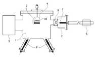
도 10 및 도 11은 현재 상용화되어 사용하고 있는 분자선 에피택시 박막 성장 장치의 구조를 나타낸 도면이다.10 and 11 are views showing the structure of a molecular beam epitaxial thin film growth apparatus that is currently commercially available.
도 10 및 도 11에 도시한 바와 같이, 일반적인 분자선 에피택시 박막 성장 장치는, 성장챔버(growth chamber; 1), 로드락챔버(load-lock chamber; 2), 준비 챔버(preparation chamber; 미도시), 진공펌프(vacuum pump; 3), 기판장착부(substrate manipulator; 4), 기판이송부재(substrate transfer rod; 5), 기판(substrate; 7), 게이트 밸브(gate valve; 8), 분자빔 증발원(effusion cell; 9), 히터(heater; 10)를 포함한다.10 and 11, a typical molecular beam epitaxial thin film growth apparatus includes a growth chamber (1), a load-lock chamber (2), and a preparation chamber (not shown). ,
이러한, 분자선 에피택시 박막 장치는 공기 중에서 세척된 기판(7)을 로드락챔버(2)에 넣고 10-6 내지 10-8 Torr 정도의 진공을 만든 후, 로드락챔버(2)와 성장챔버(1) 사이의 게이트 밸브(8)를 열고, 기판이송부재 (5)를 사용하여 기판(7)을 로드락챔버(2)에서 성장챔버(1)의 기판장착부 (4) 까지 이송한다. 성장된 박막 기판(7)은 기판이송부재(5)를 사용하여 로드락챔버(2)로 이송하고 게이트 밸브(8)를 닫은 후 로드락챔버(2)에 1기압의 기체를 주입한 후에 기판(7)을 꺼낸다. 이와 같은 과정을 반복적으로 수행하여 기판(7)에 박막을 성장시킨다.In this molecular beam epitaxy thin film apparatus, a
일반적으로 분자선 에피택시 박막 성장 장치는 고장이 빈번한 장치이다. 분자선 에피택시 박막 성장 장치의 모든 구성품이 정상적으로 작동해야만 분자선 에피택시 박막 성장 장치에 의해 박막 성장이 가능하다.In general, a molecular beam epitaxial thin film growth apparatus is a device with frequent failures. Thin film growth is possible by the molecular beam epitaxial thin film growth device only when all components of the molecular beam epitaxial thin film growth device operate normally.
한편, 도 10을 참조하면, 분자선 에피택시 박막 성장 장치는, 물질을 증발시키는 분자빔 증발원(9)의 면과 기판장착부(4)가 마주보도록 설치된다. 이때, 기판장착부(4)는 기판 면방향으로의 회전 기능을 갖는다. 기판(7)은 로드락챔버(2)로부터 기판이송부재(5)를 사용하여 이송되는데, 로드락챔버(2)의 위치는 분자빔 증발원(9) 면과 기판장착부(4)가 만드는 선과 수직한 방향에 위치된다. 여기서, 기판(7)은 수평으로 진입하여 기판이송부재(5)에 여러가지 방식으로 끼워진다.Meanwhile, referring to FIG. 10 , in the molecular beam epitaxy thin film growth apparatus, the surface of the molecular
이러한 구조를 가지는 분자선 에피택시 박막 성장 장치는, 기판(7)과 기판홀더(미도시)의 무게와 기판이송부재(5)의 무게 등으로 인하여 처짐이 발생하여 정확한 위치로 이동이 어렵게 된다. 이에 따라, 기판을 넣고 빼기가 어렵고, 사용 횟수가 늘어날수록 더욱 어려워져, 기판(7)을 떨어뜨리는 경우가 자주 발생하는 단점이 있다. 간혹 떨어진 기판을 지지하고 있는 기판 홀더가 분자빔 증발원(9)을 막게 되고, 그에 따라 성장챔버(1)를 열어야 하는 번거로움이 있다.In the molecular beam epitaxial thin film growth apparatus having such a structure, sagging occurs due to the weight of the
또한, 도 11을 참조하면, 분자선 에피택시 박막 성장 장치는, 기판장착부(4)는 두 방향으로 회전이 가능하도록 제작된다. 다시 말해, 기판장착부(4)는 기판(7)의 면방향으로의 기판을 회전시키는 것과 기판축 회전을 갖는다.Also, referring to FIG. 11 , in the molecular beam epitaxial thin film growth apparatus, the
즉, 시료를 받을 때는 기판장착부(4)를 로드락챔버(2) 방향으로 회전시켜서 기판(7)을 받고, 박막 성장시에는 기판(7)이 장착된 기판장착부(4)를 분자빔 증발원(9) 방향으로 회전시킨다.That is, when receiving a sample, the
이러한 구조를 가지는 분자선 에피택시 박막 성장 장치는, 기판(7)의 아래에 있는 히터(10)와 열전대 선(미도시)가 항상 함께 움직여야 한다. 이에 따라, 히터(10)나 열전대 선의 절연 부분이 벗겨져서 히터(10)나 열전대 선과 성장챔버(1)의 단락이나 히터(10)와 열전대 선과의 단락이 발생하여 오작동이 발생되고, 또한 히터(10)의 단락에 의한 기판(7)의 온도 변화가 발생되어 박막의 특성과 재현성 문제점을 야기한다. 또한, 기판장착부(4)를 자주 청소해야 하는 번거로움이 있다.In the molecular beam epitaxial thin film growth apparatus having such a structure, the
상술한 바와 같이, 분자선 에피택시 박막 성장 장치의 고장 원인은 다양하나, 크게 장치의 구조적 요인, 사용자의 부주의에 의한 요인, 유지보수성 요인으로 분류할 수 있다.As described above, the causes of failure of the molecular beam epitaxy thin film growth apparatus are various, but can be largely classified into a structural factor of the device, a factor due to user's carelessness, and a maintainability factor.
예컨대, 구조적 고장 요인으로는 성장챔버(1)의 내부에서 기판(7)을 이송하거나 탈부착 시에 기판(7)을 성장챔버(1)의 내부에서 떨어 뜨려서 분자빔 증발원(9)을 막거나, 히터(10) 및 온도 측정 오류로 인한 기판장착부(4)의 고장이 발생하는 경우를 들 수 있다.For example, structural failure factors include transferring the
또한, 사용자의 부주의에 의한 고장 요인으로는 뷰포트(viewport) 또는 RHEED (reflection high-energy diffraction) 셔터를 열어둔 상태로 박막 성장을 하여 뷰포트(viewport)에 박막이 코팅되어 내부를 볼 수 없는 경우, RHEED 뷰포트에 형광물질에 박막이 코팅되어 RHEED 간섭무늬를 볼 수 없는 경우, 분자빔 증발원(9)의 도가니(미도시)가 깨져 물질이 흘러내려 분자빔 증발원을 망가뜨리는 경우, 그리고 높은 증기압(vapor pressure) 물질의 사용으로 많은 물질이 코팅되어 진공펌프(3)와 진공게이지(미도시)가 정상 작동되지 않는 경우를 들 수 있다.In addition, as a cause of failure due to user's carelessness, thin film growth is performed with the viewport or RHEED (reflection high-energy diffraction) shutter open. When a thin film is coated on a fluorescent material in the RHEED viewport and the RHEED interference fringe cannot be seen, the crucible (not shown) of the molecular
또한, 유지보수성 고장 요인으로는 장기간 사용으로 게이트밸브(8)에 이물질이 끼여 공기 차단이 되지 않은 경우, 티타늄 승화 펌프(Titanium sublimation pump; 미도시) 의 필라멘트를 다 소모했을 경우, 석영두께모니터(Quartz thickness monitor; 미도시)의 석영 센서가 한계 이상 코팅되어 갈아야 하는 경우, 게이트밸브(8)나 공기압 셔터(미도시)의 공기압을 조절하는 솔레노이드 밸브(solenoid valve; 미도시)가 고장 나는 경우를 들 수 있다.In addition, as a cause of maintenance failure, when foreign substances are caught in the
참고로, 사용자 부주의에 의한 고장 요인은 사용자가 분자선 에피택시 박막 성장 장치를 사용함에 있어서 숙련도가 쌓이면 해결될 수 있고, 또한 유지보수성 고장 요인도 분자선 에피택시 박막 성장 장치의 부품 별로 수명을 고려하여 성장챔버(1)를 열 때 청소해주거나 티타늄 승화 펌프의 필라멘트를 주기적으로 갈아주면 해결할 수 있는 부분이다.For reference, the failure factor due to user negligence can be solved when the user accumulates skill in using the molecular beam epitaxial thin film growth device, and the maintenance failure factor is also grown considering the lifespan of each part of the molecular beam epitaxial thin film growth device. This can be solved by cleaning the chamber (1) when opening it or by periodically changing the filament of the titanium sublimation pump.
그러나, 구조적 고장 요인은 사용자의 숙련도나 부품을 갈아주거나 또는 장치를 청소하는 것으로는 해결되지 않는다.However, structural failure factors are not resolved by the skill of the user or by replacing parts or cleaning the device.
이에, 구조적 고장 요인이 발생되지 않을 수 있는 종래 분자선 에피택시 박막 성장 장치의 구조와 상이하게 형성되는 분자선 에피택시 박막 장치의 개발이 요구되는 실정이다.Accordingly, there is a need to develop a molecular beam epitaxial thin film device having a structure different from that of a conventional molecular beam epitaxial thin film growth device in which a structural failure factor may not occur.
본 발명의 목적은 로드락챔버를 기판장착부와 마주보도록 위치시켜 기판을 로드락챔버에서 성장챔버로 이송시키거나 성장챔버에서 로드락챔버로 이송할 때 기판을 떨어뜨리는 것을 방지하고 기판을 가열하기 위한 히터나 열전대의 단락에 의한 고장의 원인을 줄일 수 있는 분자선 에피택시 박막 성장 장치에 관한 것이다.An object of the present invention is to position the load lock chamber to face the substrate mounting part to prevent the substrate from dropping and to heat the substrate when transferring the substrate from the load lock chamber to the growth chamber or from the growth chamber to the load lock chamber. It relates to a molecular beam epitaxy thin film growth apparatus capable of reducing the cause of failure due to a short circuit of a heater or thermocouple.
본 발명이 해결하고자 하는 과제는 이상에서 언급한 과제들로 제한되지 않으며, 언급되지 않은 또 다른 과제들은 아래의 기재로부터 당업자에게 명확하게 이해될 수 있을 것이다.The problems to be solved by the present invention are not limited to the problems mentioned above, and other problems not mentioned will be clearly understood by those skilled in the art from the following description.
상기의 목적은, 본 발명에 따라, 진공펌프와 연결되어 내부가 초고진공 상태를 유지하는 성장챔버; 성장챔버의 내부에 마련되며 기판이 장착되는 기판장착부; 성장챔버의 외부에 마련되되 성장챔버와 연통되며 기판장착부에 장착되는 박막 성장을 위한 적어도 하나의 기판이 위치되는 로드락챔버; 및 기판을 로드락챔버에서 성장챔버로 이송하거나 성장챔버에서 로드락챔버로 이송하는 기판이송부재; 를 포함하며, 로드락챔버와 기판장착부는 마주보도록 배치되되, 기판이송부재의 기판 이송 경로와 동일한 직선 상에 배치되는, 분자선 에피택시 박막 성장 장치에 의해 달성될 수 있다.The above object, according to the present invention, a growth chamber connected to the vacuum pump to maintain an ultra-high vacuum inside; a substrate mounting unit provided inside the growth chamber and on which a substrate is mounted; a load lock chamber provided outside the growth chamber and communicating with the growth chamber and in which at least one substrate for growing a thin film mounted on a substrate mounting unit is positioned; and a substrate transfer member for transferring the substrate from the load lock chamber to the growth chamber or from the growth chamber to the load lock chamber. including, wherein the load lock chamber and the substrate mounting unit are disposed to face each other, and disposed on the same straight line as the substrate transport path of the substrate transport member, which may be achieved by a molecular beam epitaxial thin film growth apparatus.
분자선 에피택시 박막 성장 장치에서, 성장챔버의 내부에는, 기판장착부에 장착되는 기판의 박막 성장을 위한 증발 물질을 생성하는 적어도 하나의 분자빔 증발원이 장착되는 증발원 장착 포트; 를 더 포함하고, 증발원 장착 포트와 로드락챔버는 성장챔버의 동일한 일면에 형성되며, 증발원 장착 포트는 기판이송부재의 기판 이송 경로에 대하여 비스듬하게 배치될 수 있다.An apparatus for growing a molecular beam epitaxial thin film, comprising: an evaporation source mounting port in which at least one molecular beam evaporation source for generating evaporation material for thin film growth of a substrate mounted on a substrate mounting unit is mounted in the growth chamber; It further includes, wherein the evaporation source mounting port and the load lock chamber are formed on the same surface of the growth chamber, the evaporation source mounting port may be disposed obliquely with respect to the substrate transfer path of the substrate transfer member.
분자선 에피택시 박막 성장 장치에서, 로드락챔버와 성장챔버 사이를 연결하는 연결 유로는 게이트 밸브에 의해 개폐되며, 기판의 박막 성장시에는 연결 유로는 개방되고 기판은 기판이송부재에 의해 개방된 연결 유로를 통해 로드락챔버에서 성장챔버로 이동되어 기판장착부에 장착되고, 기판의 박막 성장중에는 기판이송부재가 성장챔버로부터 빠져나온 상태에서 연결 유로가 폐쇄되며, 기판의 박막 성장 완료시에는 연결 유로는 다시 개방되고 기판은 기판이송부재에 의하여 개방된 연결 유로를 통해 기판장착부에서 분리되어 성장챔버에서 로드락챔버로 이동될 수 있다.In the molecular beam epitaxy thin film growth apparatus, the connection flow path connecting the load lock chamber and the growth chamber is opened and closed by a gate valve, the connection flow path is opened when the thin film is grown on the substrate, and the substrate is the connection flow path opened by the substrate transfer member is moved from the load lock chamber to the growth chamber through and the substrate may be separated from the substrate mounting unit through a connection passage opened by the substrate transfer member and moved from the growth chamber to the load lock chamber.
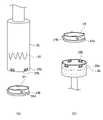
분자선 에피택시 박막 성장 장치에서, 기판은 기판홀더에 고정하며 기판홀더에는 기판장착부 및 기판이송부재와 결합되도록 적어도 하나의 결합 돌기가 마련되고, 기판이송부재 및 기판장착부에는 결합 돌기가 삽입 고정되도록 결합 돌기와 대응되는 형태로 마련되는 적어도 하나의 결합홈이 형성될 수 있다.In the molecular beam epitaxy thin film growth apparatus, a substrate is fixed to a substrate holder, and at least one coupling protrusion is provided in the substrate holder to be coupled to the substrate mounting part and the substrate transport member, and the coupling protrusion is inserted and fixed to the substrate transport member and the substrate mounting part. At least one coupling groove provided in a shape corresponding to the protrusion may be formed.
분자선 에피택시 박막 성장 장치에서, 기판이송부재에는, 기판홀더와의 결합을 용이하게 하는 기판연결부가 결합되고, 기판연결부에는 기판홀더의 결합 돌기와 대응되는 적어도 하나의 결합홈이 형성될 수 있다.In the molecular beam epitaxy thin film growth apparatus, a substrate connection part for facilitating coupling to the substrate holder is coupled to the substrate transfer member, and at least one coupling groove corresponding to the coupling protrusion of the substrate holder may be formed in the substrate connection part.
분자선 에피택시 박막 성장 장치에서, 기판의 박막 성장시, 기판홀더는 기판홀더의 결합 돌기가 기판연결부의 결합홈과 결합된 상태로 기판이송부재에 의해 로드락챔버에서 성장챔버로 이동되어 기판연결부의 결합홈과의 결합은 해제되고 기판장착부의 결합홈과 결합되어 성장챔버의 내부에 위치되며, 기판의 박막 성장 완료시, 기판홀더는 기판홀더의 결합 돌기와 기판장착부의 결합홈과의 결합은 해제되고 기판연결부의 결합홈과 다시 결합된 상태로 기판이송부재에 의해 성장챔버에서 로드락챔버로 이동될 수 있다.In the molecular beam epitaxy thin film growth apparatus, when the thin film of the substrate is grown, the substrate holder is moved from the load lock chamber to the growth chamber by the substrate transfer member in a state where the coupling protrusion of the substrate holder is coupled to the coupling groove of the substrate connection part, The coupling with the coupling groove is released and the coupling groove of the substrate mounting part is coupled to the inside of the growth chamber, and when the thin film growth of the substrate is completed, the substrate holder is released from the coupling between the coupling protrusion of the substrate holder and the coupling groove of the substrate mounting part, It may be moved from the growth chamber to the load lock chamber by the substrate transfer member in a state in which it is re-engaged with the coupling groove of the substrate connection part.
분자선 에피택시 박막 성장 장치에서, 결합홈에는, 삽입 고정되는 결합 돌기가 이탈되는 것을 방지하기 위하여 일측으로 절곡되는 절곡부가 형성될 수 있다.In the molecular beam epitaxial thin film growth apparatus, a bent portion bent to one side may be formed in the coupling groove to prevent the coupling protrusion being inserted and fixed from being separated.
분자선 에피택시 박막 성장 장치에서, 로드락챔버는, 박막 성장을 위하여 성장챔버로 이동되는 적어도 하나의 기판이 저장되는 기판저장부를 더 포함할 수 있다.In the molecular beam epitaxial thin film growth apparatus, the load lock chamber may further include a substrate storage unit for storing at least one substrate moved to the growth chamber for thin film growth.
분자선 에피택시 박막 성장 장치에서, 기판저장부는, 로드락챔버의 중심에 고정되어 일측 또는 타측 방향으로 회전되는 회전부재; 및 회전부재에 설치되며 내부에 복수 개의 기판이 저장되는 복수 개의 저장 유닛; 을 포함하고, 회전부재에는 저장 유닛이 설치되지 않은 위치에 관통 형성되는 기판이동부가 마련되되, 기판을 로드락챔버에서 성장챔버로 이동시키거나 성장챔버에서 로드락챔버로 이송하고자 할 경우에는 기판이송부재의 기판 이동 경로와 기판이동부가 일직선이 되도록 회전부재를 회전시킬 수 있다.In the molecular beam epitaxial thin film growth apparatus, the substrate storage unit includes: a rotating member fixed to the center of the load lock chamber and rotated in one direction or the other; and a plurality of storage units installed on the rotating member and storing a plurality of substrates therein; and a substrate moving part penetratingly formed in a position where the storage unit is not installed is provided in the rotating member, and when the substrate is to be moved from the load lock chamber to the growth chamber or transferred from the growth chamber to the load lock chamber, the substrate The rotation member may be rotated so that the substrate movement path of the transfer member and the substrate transfer unit are in a straight line.
분자선 에피택시 박막 성장 장치에서, 기판이송부재의 기판 이송 경로와 회전부재의 회전 중심은 서로 다른 위치를 가지도록 마련될 수 있다.In the molecular beam epitaxial thin film growth apparatus, the substrate transfer path of the substrate transfer member and the rotation center of the rotating member may be provided to have different positions.
분자선 에피택시 박막 성장 장치에서, 저장 유닛은, 적어도 일단부가 개방된 면으로 형성되고, 내부에 기판이 위치되며 기판홀더의 결합 돌기가 끼워지는 적어도 하나의 지지홈이 마련된 케이싱; 케이싱의 내부에 위치되며 케이싱에 위치되는 기판이 놓여지는 지지부재; 및 지지부재에 끼워진 상태로 케이싱과 지지부재 사이에 위치되어 지지부재에 놓여진 복수 개의 기판홀더를 탄성 지지하는 탄성체; 를 포함할 수 있다.In the molecular beam epitaxy thin film growth apparatus, the storage unit includes: a casing formed with an open surface at at least one end, a substrate positioned therein, and at least one support groove through which the coupling protrusion of the substrate holder is fitted; a support member positioned inside the casing and on which a substrate positioned in the casing is placed; and an elastic body positioned between the casing and the support member while being inserted into the support member to elastically support the plurality of substrate holders placed on the support member. may include.
분자선 에피택시 박막 성장 장치에서, 로드락챔버에는, 저장된 기판을 로드락챔버아웃개싱(outgassing) 하기 위한 히터가 마련될 수 있다.In the molecular beam epitaxial thin film growth apparatus, a heater may be provided in the load lock chamber for outgassing the stored substrate into the load lock chamber.
분자선 에피택시 박막 성장 장치에서, 성장챔버에는, 기판장착부에 장착된 기판에 이물질이 부착되는 것을 차단하기 위한 셔터가 마련되고, 셔터는 기판장착부와 인접한 위치에 설치되되 기판장착부 쪽으로 회동 가능하게 설치될 수 있다.In the molecular beam epitaxy thin film growth apparatus, the growth chamber is provided with a shutter for blocking foreign matter from adhering to the substrate mounted on the substrate mounting unit, and the shutter is installed at a position adjacent to the substrate mounting unit and rotatably installed toward the substrate mounting unit. can
분자선 에피택시 박막 성장 장치에서, 기판장착부는, 성장챔버에 대해 일측 또는 타측 방향으로 회전 가능하게 설치되고, 장착되는 기판을 가열하기 위한 히팅부재가 구비될 수 있다.In the molecular beam epitaxial thin film growth apparatus, the substrate mounting unit may be rotatably installed in one direction or the other direction with respect to the growth chamber, and a heating member for heating the mounted substrate may be provided.
분자선 에피택시 박막 성장 장치에서, 증발원 포트에 설치되는 분자빔 증발원은 분자빔 증발원으로부터 발생되는 증발 물질이 기판장착부를 향하도록 배치되며, 성장챔버에는 기판장착부를 향해 배출되는 증발 물질의 양을 조절하기 위한 조절부재가 마련될 수 있다.In the molecular beam epitaxy thin film growth apparatus, the molecular beam evaporation source installed in the evaporation source port is disposed so that evaporation material generated from the molecular beam evaporation source faces the substrate mounting unit, and the growth chamber controls the amount of evaporation material discharged toward the substrate mounting unit. An adjustment member may be provided for
분자선 에피택시 박막 성장 장치에서, 성장챔버에는 기판의 박막 성장 시에 성장챔버의 내부의 온도를 하강시키기 위한 냉각부재가 마련될 수 있다.In the molecular beam epitaxial thin film growth apparatus, the growth chamber may be provided with a cooling member for lowering the temperature inside the growth chamber when the thin film of the substrate is grown.
분자선 에피택시 박막 성장 장치는, 분자선 에피택시 박막 성장 장치가 설치되는 일면에 대한 분자선 에피택시 박막 성장 장치의 경사도를 조절하기 위하여 마련되는 적어도 하나의 챔버 지지대를 더 포함할 수 있다.The molecular beam epitaxial thin film growth apparatus may further include at least one chamber support provided to adjust the inclination of the molecular beam epitaxial thin film growth apparatus with respect to one surface on which the molecular beam epitaxial thin film growth apparatus is installed.
본 발명의 분자선 에피택시 박막 성장 장치는, 로드락챔버와 기판장착부를 마주보도록 배치하되 로드락챔버에서 성장챔버 또는 성장챔버에서 로드락챔버로 기판을 이송하는 기판이송부재의 기판 이송 경로와 동일한 직선 상에 배치함으로써, 기판을 이송하는 과정에서 기판을 떨어뜨리는 확률을 대폭 감소시켜 박막 성장 장치를 장기간 사용할 수 있는 이점이 있다.In the molecular beam epitaxial thin film growth apparatus of the present invention, the load lock chamber and the substrate mounting unit are arranged to face each other, but the same straight line as the substrate transfer path of the substrate transfer member for transferring the substrate from the load lock chamber to the growth chamber or from the growth chamber to the load lock chamber By arranging on the top, there is an advantage that the thin film growth apparatus can be used for a long time by greatly reducing the probability of dropping the substrate in the process of transferring the substrate.
또한, 본 발명의 분자선 에피택시 박막 성장 장치는, 기판장착부에 장착된 히터 및 열전대의 단락 등에 의한 고장의 원인을 미연에 방지함으로써 박막 성장 공정의 신뢰성을 향상시킬 수 있다.In addition, the molecular beam epitaxy thin film growth apparatus of the present invention can improve the reliability of the thin film growth process by preventing in advance a cause of failure due to a short circuit of a heater and a thermocouple mounted on a substrate mounting unit.
또한, 본 발명의 분자선 에피택시 박막 성장 장치는, 로드락챔버의 내부에 기판저장부를 구비함으로써 박막 성장을 위한 기판을 복수 개 저장할 수 있고, 저장된 로드락챔버에 열을 가함으로써 필요에 따라 아웃개싱(outgassing) 할 수 있다.In addition, in the molecular beam epitaxial thin film growth apparatus of the present invention, a plurality of substrates for thin film growth can be stored by providing a substrate storage unit inside the load lock chamber, and outgassing as needed by applying heat to the stored load lock chamber (outgassing) can be done.
도 1은 본 발명의 일 실시예에 따른 분자선 에피택시 박막 성장 장치를 나타낸 도면이다.
도 2는 도 1에 도시한 기판장착부와 기판홀더의 연결 상태 및 기판홀더와 기판이송부재의 연결 상태를 설명하기 위한 도면이다.
도 3은 도 1에 도시한 기판이송부재에 기판연결부 및 기판홀더가 결합된 상태를 나타낸 도면이다.
도 4는 도 1에 도시한 기판장착부에 기판홀더가 결합된 상태를 나타낸 도면이다.
도 5는 도 1에 도시한 로드락챔버를 설명하기 위한 도면이다.
도 6은 도 5에 도시한 저장 유닛을 설명하기 위한 도면이다.
도 7은 도 6에 도시한 저장 유닛에 기판홀더가 저장되는 방식을 설명하기 위한 도면이다.
도 8 및 도 9는 도 1에 도시한 분자선 에피택시 박막 성장 장치의 설치 상태를 설명하기 위한 도면이다.
도 10 및 도 11은 종래 분자선 에피택시 박막 성장 장치의 일예를 나타낸 도면이다.1 is a view showing a molecular beam epitaxial thin film growth apparatus according to an embodiment of the present invention.
FIG. 2 is a view for explaining a connection state between the substrate mounting unit and the substrate holder and the connection state between the substrate holder and the substrate transfer member shown in FIG. 1 .
FIG. 3 is a view showing a state in which a substrate connection part and a substrate holder are coupled to the substrate transfer member shown in FIG. 1 .
FIG. 4 is a view showing a state in which the substrate holder is coupled to the substrate mounting part shown in FIG. 1 .
5 is a view for explaining the load lock chamber shown in FIG.
FIG. 6 is a view for explaining the storage unit shown in FIG. 5 .
7 is a view for explaining a method in which the substrate holder is stored in the storage unit shown in FIG.
8 and 9 are views for explaining an installation state of the molecular beam epitaxial thin film growth apparatus shown in FIG. 1 .
10 and 11 are views showing an example of a conventional molecular beam epitaxial thin film growth apparatus.
이하, 첨부된 도면을 참고로 하여 본 발명의 실시예들에 대하여 본 발명이 속하는 기술분야에서 통상의 지식을 가진 자가 용이하게 실시할 수 있도록 상세히 설명한다. 본 발명은 여러 가지 상이한 형태로 구현될 수 있으며 여기에서 설명하는 실시예들에 한정되지 않는다.Hereinafter, with reference to the accompanying drawings, embodiments of the present invention will be described in detail so that those of ordinary skill in the art can easily carry out the present invention. The present invention may be embodied in many different forms and is not limited to the embodiments described herein.
도면들은 개략적이고 축적에 맞게 도시되지 않았다는 것을 일러둔다. 도면에 있는 부분들의 상대적인 치수 및 비율은 도면에서의 명확성 및 편의를 위해 그 크기에 있어 과장되거나 감소되어 도시되었으며, 임의의 치수는 단지 예시적인 것이지 한정적인 것은 아니다. 그리고, 둘 이상의 도면에 나타나는 동일한 구조물, 요소 또는 부품에는 동일한 참조 부호가 유사한 특징을 나타내기 위해 사용된다.It is noted that the drawings are schematic and not drawn to scale. Relative dimensions and proportions of parts in the drawings are shown exaggerated or reduced in size for clarity and convenience in the drawings, and any dimensions are illustrative only and not limiting. In addition, the same reference numerals are used to indicate similar features to the same structure, element, or part appearing in two or more drawings.
본 발명의 실시예는 본 발명의 이상적인 실시예들을 구체적으로 나타낸다. 그 결과, 도면의 다양한 변형이 예상된다. 따라서 실시예는 도시한 영역의 특정 형태에 국한되지 않으며, 예를 들면 제조에 의한 형태의 변형도 포함한다.The embodiments of the present invention specifically represent ideal embodiments of the present invention. As a result, various modifications of the drawings are expected. Accordingly, the embodiment is not limited to a specific shape of the illustrated area, and includes, for example, a shape modification by manufacturing.
이하, 첨부된 도면을 참조하여 본 발명의 일 실시예에 따른 분자선 에피택시 박막 성장 장치(10, 이하 '박막 성장 장치' 라 함)를 설명한다.Hereinafter, a molecular beam epitaxial thin film growth apparatus 10 (hereinafter referred to as a 'thin film growth apparatus') according to an embodiment of the present invention will be described with reference to the accompanying drawings.
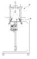
도 1, 도 3 및 도 4에 도시한 바와 같이, 본 발명의 일 실시예에 따른 박막 성장 장치(10)는 초고진공(Ultra High Vaccum) 상태를 유지하는 성장챔버(11), 성장챔버(11)의 내부에 마련되며 기판홀더(14)가 장착되는 기판장착부(25), 성장챔버(11)의 내부에 마련되며 기판(14b)이 위치되는 로드락챔버(12), 기판(14b)을 로드락챔버(12)에서 성장챔버(11)로 이송하거나 성장챔버(11)에서 로드락챔버(12)로 이송하는 기판이송부재(24)를 포함한다.1, 3 and 4, the thin
도 1을 참조하면, 성장챔버(11)는 외벽으로 둘러 쌓인 형태로 형성되며 내부가 중공(中空)으로 형성된다. 성장챔버(11)의 내부에는 로드락챔버(12)를 제외하고 기판(14b)에 박막 성장을 위한 대부분의 부품들이 배치된다.Referring to FIG. 1 , the
이러한 성장챔버(11)는 진공 펌프(16)와 연결된다. 이에 따라, 성장챔버(11)의 내부는 초고진공 상태로 형성되어 유지된다.The
이때, 성장챔버(11)와 연결되는 진공 펌프(16)는 일차 펌프(roughing pump), 터보 펌프(turbomolecular pump), 이온 펌프(ion pump), 크라이오 펌프(cryo pump), 그리고 티타늄 승화 펌프(titanium sublimation pump) 등으로 마련될 수 있으나, 반드시 이에 한정되는 것은 아니다.At this time, the
성장챔버(11)와 진공 펌프(16) 사이는 연결 유로(18a)를 통해 연결되며, 연결 유로(18a)는 게이트 밸브(18)에 의해 개폐된다.The
한편, 성장챔버(11)의 내부에는 기판장착부(25)가 마련된다.On the other hand, the inside of the
기판장착부(25)는 박막 성장을 위한 기판(14b)이 장착되는 부분으로, 성장챔버(11)의 내부에 마련된다.The
이때, 기판장착부(25)는 성장챔버(11)의 내부에서 일측 또는 타측 방향으로 회전 가능하게 마련된다. 다시 말해서, 기판장착부(25)는 기판장착구동부(13)에 의해 성장챔버(11)의 상측에 고정되어 일측 또는 타측으로 회전 가능하게 배치된다. 이에 따라, 기판(14b)의 박막 성장 시 더욱 효과적으로 기판(14b)에 박막을 성장시킬 수 있다.At this time, the
기판장착부(25)는 그 하단부에 기판홀더(14)가 장착되는 공간이 형성된다. 이때, 기판장착부(25)는 장착되는 기판홀더(14)의 형태에 따라 그 형태가 원통, 사각형 등으로 변형될 수 있다.The
여기서, 도 2의 (a)를 참조하면, 기판장착부(25)에는 적어도 하나의 결합홈(25a)이 마련된다. 결합홈(25a)은 기판장착부(25)에 기판홀더(14)가 장착되는 것을 용이하게 하기 위한 것이다. 이때, 기판홀더(14)에는 적어도 하나의 결합 돌기(14a)가 형성되는데, 결합홈(25a)은 기판홀더(14)의 결합 돌기(14a)와 대응되도록 일종의 홈(groove)의 형태로 형성된다.Here, referring to FIG. 2A , at least one
이에 따라, 기판장착부(25)의 결합홈(25a)에 기판홀더(14)의 결합 돌기(14a)가 삽입 고정됨으로써, 기판장착부(25)에 대해 기판홀더(14)가 안정적으로 위치될 수 있게 된다.Accordingly, the
한편, 기판(14b)은 기판홀더(14)에 대해 결합된 상태로 사용된다. 다시 말해서, 기판홀더(14)의 하단부에 기판(14b)이 부착된 상태로 기판장착부(25)에 장착된다. 즉, 기판장착부(25)에 기판홀더(14)가 장착되면 기판(14b)도 함께 장착되게 되는 것이다.Meanwhile, the
기판장착부(25)의 결합홈(25a)은 일측으로 절곡되는 형태를 갖는다. 다시 말해서, 기판장착부(25)의 결합홈(25a)에 삽입 고정되는 기판홀더(14)의 결합 돌기(14a)가 기판장착부(25)로부터 이탈되는 것을 방지하기 위하여 일측으로 절곡되는 절곡부(25b)가 형성된다.The
기판장착부(25)의 결합홈(25a)에 절곡부(25b)가 형성됨으로 인하여, 기판홀더(14)의 결합 돌기(14a)가 기판장착부(25)의 결합홈(25a)에 삽입되었을 때 결합홈(25a)으로부터 이탈되는 것을 방지함과 동시에 기판(14b)이 부착된 기판홀더(14)가 기판장착부(25)에 더욱 안정적으로 위치될 수 있도록 한다.Because the
또한, 기판장착부(25)에는 히팅부재(19)가 구비된다. 히팅부재(19)는 기판장착부(25)에 장착된 기판홀더(14)를 고온까지 가열하기 위한 부재이다. 참고로, 히팅부재(19)는 일종의 히터(heater)로 마련될 수 있으나, 반드시 이에 한정되는 것은 아니다.In addition, a
한편, 성장챔버(11)에는 증발원 장착 포트(15)가 형성되고, 증발원 장착 포트(15)에는 분자빔 증발원(15a)이 장착된다.Meanwhile, an evaporation
분자빔 증발원(15a)은 기판장착부(25)에 장착된 기판(14b)에 박막 성장을 위한 증발 물질을 생성하는 부재이다.The molecular
분자빔 증발원(15a)으로부터 방출된 증발 물질은 기판장착부(25)에 장착된 기판(14b)을 향해 방출된다. 참고로, 방출되는 증발 물질은 분자빔 증발원(15a)의 내부에서 가열되는 물질에 따라 달라질 수 있다.The evaporation material emitted from the molecular
여기서, 성장챔버(11)에는 셔터(20)가 마련된다. 셔터(20)는 기판장착부(25)에 장착된 기판(14b)에 이물질이 부착되는 것을 차단하기 위한 부재이다.Here, the
셔터(20)는 기판장착부(25) 쪽으로 회동 가능하게 설치되어, 기판(14b)의 표면을 보호한다.The
분자빔 증발원(15a)의 가열시 분자빔 증발원(15a)의 주위에 있던 물질 또는 이물질들이 기판장착부(25)에 장착된 깨끗한 상태의 기판(14b)에 부착될 수 있다. 그럴 경우, 기판(14b)에 박막 성장이 되더라도 불량이 발생되거나 제대로 박막이 성장되지 못하게 된다.When the molecular
이를 방지하기 위하여, 기판장착부(25)와 인접한 위치에 셔터(20)를 마련함으로써, 기판장착부(25)에 장착된 기판(14b)에 이물질이 부착되지 않도록 기판(14b)의 표면을 보호할 수 있게 된다.In order to prevent this, by providing the
참고로, 셔터(20)는 외부에서 개폐 가능하게 마련될 수 있다. 이는 외부에서 기판(14b)에 코팅을 시작하기 위한 것이다.For reference, the
또한, 성장챔버(11)에는 기판장착부(25)에 장착된 기판(14b)의 표면의 높낮이를 조절할 수 있도록 와블(wobble; 미도시)과 같은 높낮이 조절용 부재가 마련될 수도 있다.In addition, the
상술한 바와 같이, 분자빔 증발원(15a)은 기판(14b)에 박막 성장을 위한 증발 물질을 생성하고, 방출시킨다. 이때, 분자빔 증발원(15a)은 방출되는 증발 물질이 기판장착부(25) 및 기판장착부(25)에 장착된 기판(14b)을 향하도록 배치된다.As described above, the molecular
분자빔 증발원(15a)으로부터 방출되는 증발 물질의 양은 기판(14b)의 상태 등에 따라 조절되는 것이 바람직하다.The amount of evaporation material emitted from the molecular
이를 위해, 성장챔버(11)에는 조절부재(21)가 마련된다.To this end, the
조절부재(21)는 증발원 장착 포트(15)와 인접한 위치, 즉 증발원 장착 포트(15)의 선단 측에 마련되어 분자빔 증발원(15a)으로부터 기판장착부(25) 및 기판(14b)을 향해 방출되는 증발 물질의 양을 조절한다.The
조절부재(21)는 일종의 셔터(shutter)로써, 직선 운동을 통해 좌측 또는 우측으로 이동되면서 분자빔 증발원(15a)으로부터 방출되는 증발 물질의 양을 차단하여 기판(14b)의 박막 성장을 위한 증발 물질의 양을 조절한다.The
한편, 도면에는 도시하지 않았지만, 조절부재(21)는 성장챔버(11), 증발원 장착 포트(15)의 선단 측에 마련되는 것이 아니라, 분자빔 증발원(15a)의 자체에 직접적으로 마련될 수도 있다. 예를 들어, 분자빔 증발원(15a)에 마련되는 조절부재(21)는 회전되는 형태로 마련되어 분자빔 증발원(15a)으로부터 방출되는 증발 물질의 양을 조절한다.On the other hand, although not shown in the drawings, the
이와 같이, 분자빔 증발원(15a)에서 기판장착부(25)에 장착된 기판(14b)을 향해 증발 물질을 방출할 때, 분자빔 증발원(15a)에서는 많은 열이 발생되고, 발생된 열에 의해 성장챔버(11)의 온도가 높아져서 성장챔버(11)의 진공도가 저하되는 문제점이 발생된다.In this way, when the vaporization material is emitted from the molecular
이러한 문제점을 해결하기 위하여, 성장챔버(11), 즉 성장챔버(11)에 마련되는 증발원 장착 포트(15)의 주변에 냉각부재(22)가 구비된다.In order to solve this problem, the cooling
증발원 장착 포트(15) 주변의 성장챔버(11)에 구비되는 냉각부재(22)는 액체질소 또는 냉각수를 포함한 다양한 냉매가 사용되는 냉각재킷(water jacket)으로 마련된다. 이러한 냉매를 사용하는 냉각부재(22)에 의해 증발원 장착 포트(15) 주변의 성장챔버(11)가 냉각되게 된다.The cooling
한편, 성장챔버(11)의 내부에도 냉각부재(17)가 구비된다. 기판(14b)의 박막 성장 중에 분자빔 증발원(15a)에서 방출된 증발 물질 중의 일부는 기판(14b)이 아닌 성장챔버(11)의 내벽을 향해 방출된다. 그러면, 증발 물질이 성장챔버(11)의 내벽을 맞고 튕겨져 나오면서 불순물이 되어 기판(14b)의 성장된 박막의 순도를 낮출 수 있다.Meanwhile, a cooling
이때, 성장챔버(11)의 내부에 구비된 냉각부재(17)에 액체질소를 흘리면 성장챔버(11)의 내벽은 차가운 상태가 되기 때문에, 분자빔 증발원(15a)에서 방출된 증발 물질이 기판(14b)이 아닌 성장챔버(11)의 내벽을 향해 방출되더라도 차가운 냉각부재(17)에 달라붙어 기판(14b)의 박막 성장의 순도에는 영향을 미치지 않게 된다.At this time, when liquid nitrogen flows through the cooling
더욱이, 성장챔버(11)의 내벽이 냉각부재(17)에 의하여 차가워 지기 때문에, 성장챔버(11)의 내부가 초고진공 상태를 유지하는데 더욱 유리하게 될 수 있다.Moreover, since the inner wall of the
성장챔버(11)의 내부에 마련되는 냉각부재(17)는 액체질소 외 칠러(chiller)를 활용한 냉매가 사용될 수 있다. 로드락챔버(12)는 박막 성장을 위한 기판(14b)이 외부와 출입하고 보관되는 부분이다.As the cooling
로드락챔버(12)는 성장챔버(11)의 외부에 마련되되 성장챔버(11)와 연통된다. 이때, 로드락챔버(12)와 성장챔버(11)의 사이는 연결 유로(23a)에 의해 연결되고, 연결 유로(23a)는 게이트 밸브(23)에 의해 개방되거나 폐쇄된다.The
기판(14b)의 박막 성장 시에는 게이트 밸브(23)가 개방되어 연결 유로(23a)가 개방되고, 기판(14b)의 박막 성장 중에는 게이트 밸브(23)가 폐쇄되며, 기판(14b)의 박막 성장이 끝나면 게이트 밸브(23)가 다시 개방된다.When the thin film is grown on the
이에 따라, 기판(14b)의 박막 성장시 연결 유로(23a)는 개방되고 기판(14b)은 기판이송부재(24)에 의해 개방된 연결 유로(23a)를 통해 로드락챔버(12)에서 성장챔버(11)로 이동되어 기판장착부(25)에 장착된다.Accordingly, when the thin film is grown on the
기판(14b)의 박막 성장 완료시에는 연결 유로(23a)는 다시 개방되고, 기판(14b)은 기판이송부재(24)에 의해 개방된 연결 유로(23a)를 통해 기판장착부(25)에서 분리되어 성장챔버(11)에서 로드락챔버(12)로 이송된다. 박막 성장이 완료되어 로드락챔버(12)로 이송된 기판(14b)은 외부 공기 중으로 꺼내어 진다.When the thin film growth of the
참고로, 기판(14b)의 박막 성장중에는 기판이송부재(24)가 성장챔버(11)로부터 빠져나온 상태에서 연결 유로(23a)가 폐쇄된다.For reference, during the thin film growth of the
로드락챔버(12)의 내부에 위치된 기판(14b)은 연결 유로(23a)를 통해 성장챔버(11)의 내부로 이송되어 기판장착부(25)에 장착된다.The
기판(14b)은 기판이송부재(24)에 의해 로드락챔버(12)에서 성장챔버(11)로 이송되거나, 성장챔버(11)에서 박막 성장이 끝난 후에 로드락챔버(12)로 이송된다.The
기판이송부재(24)에는 기판연결부(26)가 결합된다. 기판연결부(26)는 로드락챔버(12) 및 성장챔버(11)에 위치된 기판홀더(14)와 결합되어 로드락챔버(12) 또는 성장챔버(11)로 기판홀더(14)를 이송시키기 용이하도록 하기 위한 부재이다. A
이때, 도 2의 (b)를 참조하면, 기판연결부(26)에는 적어도 하나의 결합홈(26a)이 형성된다. 기판연결부(26)의 결합홈(26a)은 기판연결부(26)에 기판홀더(14)가 장착되는 것을 용이하게 하기 위한 것으로, 결합홈(26a)은 기판홀더(14)의 결합 돌기(14a)와 대응되는 일종의 홈 형태로 형성된다.At this time, referring to FIG. 2B , at least one
여기서, 기판연결부(26)의 결합홈(26a)은 일측으로 절곡되는 형태를 갖는다. 다시 말해서, 기판연결부(26)의 결합홈(26a)에 삽입 고정되는 기판홀더(14)의 결합 돌기(14a)가 이탈되는 것을 방지하기 위하여 일측으로 절곡되는 절곡부(26b)가 형성된다.Here, the
한편, 로드락챔버(12)와 기판장착부(25)는 마주보도록 배치되고, 기판이송부재(24)의 기판 이송 경로와 동일한 직선 상에 배치된다. 다시 말해서, 로드락챔버(12)와 기판장착부(25)는 기판이송부재(24)의 기판 이송 경로의 직선 상으로 위치된다.Meanwhile, the
이에 따라, 도 3에 도시한 바와 같이, 박막 성장시, 기판홀더(14)는 기판홀더(14)의 결합 돌기(14a)가 기판연결부(26)의 결합홈(26a)과 결합된 상태로 기판이송부재(24)에 의해 로드락챔버(12)에서 성장챔버(11)로 이동되어 기판연결부(26)의 결합홈(26a)과의 결합은 해제되고 기판장착부(25)의 결합홈(25a)과 결합되어 성장챔버(11)의 내부에 위치된다.Accordingly, as shown in FIG. 3 , when the thin film is grown, the
반대로, 도 4에 도시한 바와 같이, 기판(14b)의 박막 성장 완료시, 기판홀더(14)는 기판홀더(14)의 결합 돌기(14a)와 기판장착부(25)의 결합홈(15a)과의 결합은 해제되고 기판연결부(26)의 결합홈(26a)과 다시 결합된 상태로 기판이송부재(24)에 의해 성장챔버(11)에서 로드락챔버(12)로 이동된다.Conversely, as shown in FIG. 4 , when the thin film growth of the
한편, 박막 성장 장치(10)에서 가장 많은 시간이 소요되는 부분은 공기 중 로드락챔버(12)를 노출하고 기판(14b)을 넣은 후 10-6Torr 까지 진공도를 만드는 과정이다. 이에, 박막 성장 장치(10)에서 여러 개의 기판(14b)이 한 번에 준비될 경우 기판(14b)의 박막 성장에 필요한 시간을 대폭 줄일 수 있다.On the other hand, the part that takes the most time in the thin
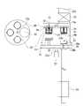
도 5 내지 도 7에 도시한 바와 같이, 본 발명의 일 실시예에 따른 로드락챔버(12)는 복수 개의 기판(14b)이 저장되는 기판저장부를 더 포함한다.5 to 7 , the
기판저장부는 로드락챔버(12)의 내부에 구비되어 기판이송부재(24)를 통해 성장챔버(11)로 이동되는 적어도 하나, 바람직하게는 복수 개의 기판(14b)이 구비된다.The substrate storage unit includes at least one, preferably a plurality of
이러한 기판저장부는 회전부재(28) 및 저장 유닛(29)을 포함한다.The substrate storage unit includes a rotating
회전부재(28)는 로드락챔버(12)의 중심에 설치된 회전구동부(27)의 회전축(27a)에 고정되어 일측 또는 타측 방향으로 회전 가능하게 마련된다.The rotating
회전부재(28)는 어느 정도의 두께를 갖는 원형의 판(plate)으로 마련된다.The rotating
참고로, 회전부재(28)의 회전 중심은 기판이송부재(24)의 기판 이송 경로와 서로 다른 위치를 가지도록 마련된다. 다시 말해서, 회전부재(28)의 회전 중심은 기판이송부재(24)의 기판 이송 경로에 대해 벗어난 상태로 외곽에 위치된다.For reference, the rotation center of the rotating
저장 유닛(29)은 복수 개의 기판(14b)이 저장되는 부분으로, 회전부재(28)에 삽입 고정된다.The
이러한, 저장 유닛(29)은 복수 개의 기판(14b)이 저장될 수 있도록 중공(中空)의 공간이 마련된다.The
한편, 회전부재(28)에는 저장 유닛(29)이 설치되지 않은 위치에 관통 형성되는 기판이동부(30)가 마련된다.On the other hand, the
기판이동부(30)는 빈 공간을 의미하며, 기판(14b)을 로드락챔버(12)에서 성장챔버(11) 또는 성장챔버(11)에서 로드락챔버(12)로 이동되도록 하기 위한 부분이다.The
로드락챔버(12)의 기판저장부에 저장된 기판(14b)을 로드락챔버(12)에서 성장챔버(11)로 이동시키거나 성장챔버(11)에서 로드락챔버(12)로 이송하고자 할 경우에는, 기판이송부재(24)의 기판 이동 경로와 기판이동부(30)의 중심이 일직선이 되도록 위치시켜야 한다.When the
이를 위해, 회전구동부(27)를 이용하여 회전부재(28)를 회전시켜서 기판이동부(30)와 기판이송부재(24)를 일직선 상에 위치되도록 할 수 있다.To this end, the
한편, 저장 유닛(29)은 케이싱(34), 지지부재(33) 및 탄성체(32)를 포함한다.Meanwhile, the
저장 유닛(29)의 케이싱(34)은 적어도 일단부, 즉 하단부가 개방된 면으로 형성되고, 내부에 기판홀더(14)가 위치된다.The
이를 위해, 케이싱(34)에는 기판홀더(14)의 결합 돌기(14a)가 끼워지는 적어도 하나의 지지홈(34a)이 마련된다. 지지홈(34a)은 기판홀더(14)의 결합 돌기(14a)와 대응되는 형태의 홈으로 마련된다. 참고로, 지지홈(34a)은 일측 방향으로 절곡된 절곡부(34b)가 마련되어 지지홈(34a)에 끼워진 기판홀더(14)의 결합 돌기(14a)가 쉽게 이탈되지 않도록 할 수 있다.To this end, the
지지부재(33)는 케이싱(34)의 내부에 위치되며 케이싱(34)에 위치되는 기판홀더(14)가 놓여진다. 다시 말해서, 지지부재(33)는 일종의 원판의 형태로 형성되어 복수 개의 기판홀더(14)가 적층되는 형태로 놓여지게 된다. 지지부재(33)의 상단부는 케이싱(34)에 형성된 광통홈(34c)을 관통하도록 마련된다.The
이때, 지지부재(33)에는 탄성체(32)가 끼워진다.At this time, the
탄성체(32)는 지지부재(33)에 끼워진 상태로 케이싱(34)과 지지부재(33) 사이에서 지지부재(33)에 놓여진 복수 개의 기판홀더(14)를 탄성 지지하여 케이싱(34)의 내부에 위치되도록 한다.The
탄성체(32)는 탄성을 가지는 스프링(spring)으로 마련될 수 있으며, 반드시 이에 한정되는 것은 아니다.The
도 6 및 도 7을 참조하여, 로드락챔버(12)의 저장 유닛(29)에 기판홀더(14)가 저장되는 방식을 간단히 설명한다.A method in which the
우선, 저장 유닛(29)의 케이싱(34)의 내부에 지지부재(33)를 위치시킨다. 이때, 지지부재(33)는 탄성체(32)가 끼워진 상태로 케이싱(34)의 내부에 위치된다.First, the
그 하단부로 기판홀더(14)를 밀어 넣으면, 탄성체(32)의 탄성력에 의하여 케이싱(34)의 내부에 기판홀더(14)가 적층 형태로 저장되는 것이다.When the
이때, 상술한 바와 같이, 케이싱(34)에 형성된 지지홈(34a)에 일측 방향으로 절곡된 절곡부(34b)가 형성됨으로써 기판홀더(14)가 케이싱(34)으로부터 이탈되지 않고, 케이싱(34)의 내부에 위치되게 된다.At this time, as described above, the
즉, 더욱 간단히 설명하면, 도 7의 (a), (b), (c) 순으로 기판홀더(14)가 케이싱(34)의 내부에 적층되어 저장되는 형태를 갖게 된다.That is, more simply, the
참고로, 도면에는 하나의 저장 유닛(29)에 3개의 기판홀더(14)가 저장되는 것으로 도시하였으나, 반드시 이에 한정되는 것은 아니며 저장 유닛(29), 즉 케이싱(34)의 깊이를 크게 함으로써 케이싱(34)에 저장되는 기판홀더(14)의 개수를 늘릴 수 있다.For reference, the drawing shows that the three
또한, 상술한 바와 같이, 기판홀더(14)에 기판(14b)이 결합되기 때문에, 저장 유닛(29)에는 기판홀더(14)와 함께 기판(14b)도 적층되어 저장된다.In addition, as described above, since the
한편, 로드락챔버(12)에는 히터(31)가 마련된다.On the other hand, the
히터(31)는 로드락챔버에 저장된 기판(14b)을 박막 성장전 아웃개싱(outgassing) 하기 위한 부재이다.The
히터(31)를 이용하여 로드락챔버(12)에 저장된 기판(14b)의 아웃개싱을 수행하여 박막 성장 장치(10)에서 박막 성장에 필요한 시간을 줄일 수 있는 이점이 있다.There is an advantage in that the time required for thin film growth in the thin
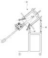
한편, 도 8 및 도 9를 참조하면, 본 발명의 일 실시예에 따른 박막 성장 장치(10)는 적어도 하나의 챔버 지지대(36)를 포함할 수 있다.Meanwhile, referring to FIGS. 8 and 9 , the thin
챔버 지지대(36)는 성장챔버(11)의 외측에 설치되어 박막 성장 장치(10)가 설치되는 일면에 대한 박막 성장 장치(10)의 경사도를 조절할 수 있다.The
예를 들어, 도 8에 도시한 바와 같이, 챔버 지지대(36)를 성장챔버(11)의 외측에 높이를 다르게 하여 배치하게 되면, 기판(14b)의 이동시 기판홀더(14)를 떨어뜨리더라도 박막 성장 장치(10)의 고장 없이 오랜 기간 사용할 수 있는 이점이 있다.For example, as shown in FIG. 8 , if the
또한, 도 9에 도시한 바와 같이, 챔버 지지대(36)를 수직으로 배치하게 되면, 박막 성장 장치(10)의 설치 공간을 줄일 수 있는 이점이 있다.In addition, as shown in FIG. 9 , when the
상기한 구성에 의하여 본 발명의 일 실시예에 따른 분자선 에피택시 박막 성장 장치(10)는, 로드락챔버(12)와 기판장착부(25)를 마주보도록 배치하되 로드락챔버(12)에서 성장챔버(11) 또는 성장챔버(11)에서 로드락챔버(12)로 기판(14b)을 이송하는 기판이송부재(24)의 기판 이송 경로와 동일한 직선 상에 배치함으로써, 기판(14b)을 이송하는 과정에서 기판홀더(14)를 떨어뜨리는 확률을 대폭 감소시켜 박막 성장 장치(10)를 장기간 사용할 수 있는 이점이 있다.According to the above configuration, in the molecular beam epitaxial thin
또한, 본 발명의 분자선 에피택시 박막 성장 장치(10)는, 기판장착부(25) 자체가 회전하기 때문에 기판장착부(25)에 장착된 히터(31) 및 열전대(미도시)의 단락 등에 의한 고장의 원인을 미연에 방지함으로써 박막 성장 공정의 신뢰성을 향상시킬 수 있다.In addition, in the molecular beam epitaxy thin
이상과 같이 본 발명의 일 실시예에서는 구체적인 구성 요소 등과 같은 특정 사항들과 한정된 실시예 및 도면에 의해 설명되었으나 이는 본 발명의 보다 전반적인 이해를 돕기 위해서 제공된 것일 뿐, 본 발명은 상기의 실시예에 한정되는 것은 아니며, 본 발명이 속하는 분야에서 통상적인 지식을 가진 자라면 이러한 기재로부터 다양한 수정 및 변형이 가능하다. 따라서, 본 발명의 사상은 설명된 실시예에 국한되어 정해져서는 아니 되며, 후술하는 청구범위뿐 아니라 이 청구범위와 균등하거나 등가적 변형이 있는 모든 것들은 본 발명 사상의 범주에 속한다고 할 것이다.As described above, in one embodiment of the present invention, specific matters such as specific components, etc., and limited embodiments and drawings have been described, but these are only provided to help a more general understanding of the present invention, and the present invention is not limited to the above embodiments. It is not limited, and various modifications and variations are possible from these descriptions by those of ordinary skill in the art to which the present invention pertains. Accordingly, the spirit of the present invention should not be limited to the described embodiments, and not only the claims described below, but also all of the claims and all equivalents or equivalent modifications thereof will fall within the scope of the spirit of the present invention.
10: 분자선 에피택시 박막 성장 장치
11: 성장챔버 12: 로드락챔버
14: 기판홀더14a: 결합 돌기
15: 증발원 장착 포트 15a: 분자빔 증발원
16: 진공 펌프17, 22: 냉각 부재
18, 23: 게이트 밸브18a, 23a: 연결 유로
20: 셔터21: 조절부재
24: 기판이송부재25: 기판장착부
26: 기판연결부25a, 26a: 결합홈
27: 회전구동부
28: 회전부재29: 저장 유닛
30: 기판이동부31: 히터
32: 탄성체33: 지지부재
34: 케이싱34a: 지지홈10: molecular beam epitaxy thin film growth apparatus
11: Growth chamber 12: Load lock chamber
14:
15: evaporation
16:
18, 23:
20: shutter 21: adjustment member
24: substrate transfer member 25: substrate mounting unit
26:
27: rotation drive unit
28: rotating member 29: storage unit
30: substrate moving unit 31: heater
32: elastic body 33: support member
34: casing 34a: support groove
Claims (17)
Translated fromKorean성장챔버의 내부에 마련되며 기판이 장착되는 기판장착부;
성장챔버의 외부에 마련되되 성장챔버와 연통되며 기판장착부에 장착되는 박막 성장을 위한 적어도 하나의 기판이 위치되는 로드락챔버; 및
기판을 로드락챔버에서 성장챔버로 이송하거나 성장챔버에서 로드락챔버로 이송하는 기판이송부재;
를 포함하며,
로드락챔버와 기판장착부는 마주보도록 배치되되, 기판이송부재의 기판 이송 경로와 동일한 직선 상에 배치되고,
로드락챔버와 성장챔버 사이는 연결 유로에 의해 연결되며,
기판의 박막 성장시에는 연결 유로가 개방되되, 기판이송부재는 직선의 이송 경로를 따라 개방된 연결 유로를 통과하여 로드락챔버에서 성장챔버로 기판을 이동시켜서 기판장착부에 장착되도록 하고,
기판의 박막 성장중에는 기판이송부재가 직선의 이송 경로를 따라서 성장챔버로부터 빠져나온 상태에서 연결 유로가 폐쇄되며,
기판의 박막 성장 완료시에는 연결 유로는 다시 개방되되, 기판이송부재는 직선의 이송 경로를 따라 다시 개방된 연결 유로를 통과하여 기판을 성장챔버의 기판장착부에서 분리하여 로드락챔버로 이동되도록 마련된, 분자선 에피택시 박막 장치.
a growth chamber connected to a vacuum pump to maintain an ultra-high vacuum inside;
a substrate mounting unit provided inside the growth chamber and on which a substrate is mounted;
a load lock chamber provided outside the growth chamber and communicating with the growth chamber and in which at least one substrate for growing a thin film mounted on a substrate mounting unit is positioned; and
a substrate transfer member for transferring the substrate from the load lock chamber to the growth chamber or from the growth chamber to the load lock chamber;
includes,
The load lock chamber and the substrate mounting part are arranged to face each other, and are arranged on the same straight line as the substrate transport path of the substrate transport member,
The load lock chamber and the growth chamber are connected by a connecting flow path,
When the thin film of the substrate is grown, the connection passage is opened, and the substrate transfer member moves the substrate from the load lock chamber to the growth chamber through the open connection passage along the straight transfer path to be mounted on the substrate mounting unit,
During the growth of the thin film on the substrate, the connection passage is closed while the substrate transfer member is drawn out from the growth chamber along a straight transfer path,
When the thin film growth of the substrate is completed, the connection passage is opened again, and the substrate transfer member passes through the connected passage again along a straight transfer path to separate the substrate from the substrate mounting part of the growth chamber and move to the load lock chamber. Epitaxy thin film device.
성장챔버의 내부에는,
기판장착부에 장착되는 기판의 박막 성장을 위한 증발 물질을 생성하는 적어도 하나의 분자빔 증발원이 장착되는 증발원 장착 포트; 를 더 포함하고,
증발원 장착 포트와 로드락챔버는 성장챔버의 동일한 일면에 형성되며,
증발원 장착 포트는 기판이송부재의 기판 이송 경로에 대하여 비스듬하게 배치되는, 분자선 에피택시 박막 성장 장치.
According to claim 1,
Inside the growth chamber,
an evaporation source mounting port on which at least one molecular beam evaporation source for generating an evaporation material for thin film growth of a substrate mounted on the substrate mounting unit is mounted; further comprising,
The evaporation source mounting port and the load lock chamber are formed on the same side of the growth chamber,
The evaporation source mounting port is disposed obliquely with respect to the substrate transfer path of the substrate transfer member, molecular beam epitaxial thin film growth apparatus.
로드락챔버와 성장챔버 사이를 연결하는 연결 유로는 게이트 밸브에 의해 개폐되는, 분자선 에피택시 박막 성장 장치.
According to claim 1,
A molecular beam epitaxy thin film growth apparatus, in which a connection passage connecting the load lock chamber and the growth chamber is opened and closed by a gate valve.
기판은 기판홀더에 고정되며,
기판홀더에는 기판장착부 및 기판이송부재와 결합되도록 적어도 하나의 결합 돌기가 마련되고,
기판이송부재 및 기판장착부에는 결합 돌기가 삽입 고정되도록 결합 돌기와 대응되는 형태로 마련되는 적어도 하나의 결합홈이 형성되는, 분자선 에피택시 박막 성장 장치.
According to claim 1,
The board is fixed to the board holder,
At least one coupling protrusion is provided on the substrate holder to be coupled to the substrate mounting part and the substrate transfer member,
A molecular beam epitaxy thin film growth apparatus, wherein at least one coupling groove provided in a shape corresponding to the coupling protrusion is formed in the substrate transfer member and the substrate mounting part so that the coupling protrusion is inserted and fixed.
기판이송부재에는,
기판홀더와의 결합을 용이하게 하는 기판연결부가 결합되고,
기판연결부에는 기판홀더의 결합 돌기와 대응되는 적어도 하나의 결합홈이 형성되는, 분자선 에피택시 박막 성장 장치.
5. The method of claim 4,
In the substrate transfer member,
A board connection part that facilitates coupling with the board holder is coupled,
A molecular beam epitaxial thin film growth apparatus, wherein at least one coupling groove corresponding to the coupling protrusion of the substrate holder is formed in the substrate connection part.
기판의 박막 성장시, 기판홀더는 기판홀더의 결합 돌기가 기판연결부의 결합홈과 결합된 상태로 기판이송부재에 의해 로드락챔버에서 성장챔버로 이동되어 기판연결부의 결합홈과의 결합은 해제되고 기판장착부의 결합홈과 결합되어 성장챔버의 내부에 위치되며,
기판의 박막 성장 완료시, 기판홀더는 기판홀더의 결합 돌기와 기판장착부의 결합홈과의 결합은 해제되고 기판연결부의 결합홈과 다시 결합된 상태로 기판이송부재에 의해 성장챔버에서 로드락챔버로 이동되는, 분자선 에피택시 박막 성장 장치.
5. The method of claim 4,
When the thin film of the substrate is grown, the substrate holder is moved from the load lock chamber to the growth chamber by the substrate transfer member in a state in which the coupling protrusion of the substrate holder is coupled to the coupling groove of the substrate connection part, and the coupling with the coupling groove of the substrate connection part is released. It is combined with the coupling groove of the substrate mounting part and is located inside the growth chamber,
When the thin film growth of the substrate is completed, the substrate holder is moved from the growth chamber to the load lock chamber by the substrate transfer member in a state in which the coupling between the coupling protrusion of the substrate holder and the coupling groove of the substrate mounting part is released and re-coupled with the coupling groove of the substrate connection part. A molecular beam epitaxy thin film growth apparatus.
결합홈에는,
삽입 고정되는 결합 돌기가 이탈되는 것을 방지하기 위하여 일측으로 절곡되는 절곡부가 형성되는, 분자선 에피택시 박막 성장 장치.
5. The method of claim 4,
In the coupling groove,
A molecular beam epitaxial thin film growth apparatus in which a bent portion bent to one side is formed to prevent the insertion and fixed coupling protrusions from being separated.
로드락챔버는,
박막 성장을 위하여 성장챔버로 이동되는 적어도 하나의 기판이 저장되는 기판저장부를 더 포함하는, 분자선 에피택시 박막 성장 장치.
5. The method of claim 4,
load lock chamber,
Molecular beam epitaxy thin film growth apparatus, further comprising a substrate storage unit for storing at least one substrate moved to the growth chamber for thin film growth.
기판저장부는,
로드락챔버의 중심에 고정되어 일측 또는 타측 방향으로 회전되는 회전부재; 및
회전부재에 설치되며 내부에 복수 개의 기판이 저장되는 복수 개의 저장 유닛; 을 포함하고,
회전부재에는 저장 유닛이 설치되지 않은 위치에 관통 형성되는 기판이동부가 마련되되,
기판을 로드락챔버에서 성장챔버로 이동시키거나 성장챔버에서 로드락챔버로 이송하고자 할 경우에는 기판이송부재의 기판 이동 경로와 기판이동부가 일직선이 되도록 회전부재를 회전시키는, 분자선 에피택시 박막 성장 장치.
9. The method of claim 8,
The substrate storage unit,
a rotating member fixed to the center of the load lock chamber and rotated in one direction or the other; and
a plurality of storage units installed on the rotating member and storing a plurality of substrates therein; including,
The rotating member is provided with a substrate moving part penetratingly formed in a position where the storage unit is not installed,
Molecular beam epitaxy thin film growth, which rotates the rotating member so that the substrate moving path of the substrate transfer member and the substrate moving part are in a straight line when the substrate is moved from the load lock chamber to the growth chamber or transferred from the growth chamber to the load lock chamber Device.
기판이송부재의 기판 이송 경로와 회전부재의 회전 중심은 서로 다른 위치를 가지도록 마련되는, 분자선 에피택시 박막 성장 장치.
10. The method of claim 9,
A molecular beam epitaxial thin film growth apparatus, wherein the substrate transfer path of the substrate transfer member and the rotation center of the rotating member have different positions.
저장 유닛은,
적어도 일단부가 개방된 면으로 형성되고, 내부에 기판홀더가 위치되며 기판홀더의 결합 돌기가 끼워지는 적어도 하나의 지지홈이 마련된 케이싱;
케이싱의 내부에 위치되며 케이싱에 위치되는 기판홀더가 놓여지는 지지부재; 및
지지부재에 끼워진 상태로 케이싱과 지지부재 사이에 위치되어 지지부재에 놓여진 복수 개의 기판홀더를 탄성 지지하는 탄성체;
를 포함하는, 분자선 에피택시 박막 성장 장치.
10. The method of claim 9,
storage unit,
a casing having at least one end formed with an open surface, having a substrate holder positioned therein, and having at least one support groove into which a coupling protrusion of the substrate holder is fitted;
a support member positioned inside the casing and on which the substrate holder positioned in the casing is placed; and
an elastic body positioned between the casing and the support member in a state of being inserted into the support member to elastically support the plurality of substrate holders placed on the support member;
Including, molecular beam epitaxy thin film growth apparatus.
로드락챔버에는,
저장된 기판을 로드락챔버아웃개싱(outgassing) 하기 위한 히터가 마련되는, 분자선 에피택시 박막 성장 장치.
12. The method of claim 11,
In the load lock chamber,
A heater for outgassing the stored substrate in the load lock chamber is provided, a molecular beam epitaxial thin film growth apparatus.
성장챔버에는,
기판장착부에 장착된 기판에 이물질이 부착되는 것을 차단하기 위한 셔터가 마련되고,
셔터는 기판장착부와 인접한 위치에 설치되되 기판장착부 쪽으로 회동 가능하게 설치되는, 분자선 에피택시 박막 성장 장치.
According to claim 1,
In the growth chamber,
A shutter is provided to block foreign substances from adhering to the substrate mounted on the substrate mounting unit,
A molecular beam epitaxial thin film growth apparatus, wherein the shutter is installed at a position adjacent to the substrate mounting unit and rotatably installed toward the substrate mounting unit.
기판장착부는,
성장챔버에 대해 일측 또는 타측 방향으로 회전 가능하게 설치되고,
장착되는 기판을 가열하기 위한 히팅부재가 구비되는, 분자선 에피택시 박막 성장 장치.
14. The method of claim 13,
The board mounting part,
It is installed rotatably in one or the other direction with respect to the growth chamber,
Molecular beam epitaxial thin film growth apparatus provided with a heating member for heating the mounted substrate.
증발원 포트에 설치되는 분자빔 증발원은 분자빔 증발원으로부터 발생되는 증발 물질이 기판장착부를 향하도록 배치되며,
성장챔버에는 기판장착부를 향해 방출되는 증발 물질의 양을 조절하기 위한 조절부재가 마련되는, 분자선 에피택시 박막 성장 장치.
3. The method of claim 2,
The molecular beam evaporation source installed in the evaporation source port is disposed so that the evaporation material generated from the molecular beam evaporation source faces the substrate mounting unit,
Molecular beam epitaxy thin film growth apparatus, wherein the growth chamber is provided with a control member for controlling the amount of evaporation material emitted toward the substrate mounting portion.
성장챔버에는 기판의 박막 성장 시에 성장챔버의 내부의 온도를 하강시키기 위한 냉각부재가 마련되는, 분자선 에피택시 박막 성장 장치.
According to claim 1,
A molecular beam epitaxy thin film growth apparatus, wherein the growth chamber is provided with a cooling member for lowering the temperature inside the growth chamber when the thin film of the substrate is grown.
분자선 에피택시 박막 성장 장치는,
분자선 에피택시 박막 성장 장치가 설치되는 일면에 대한 분자선 에피택시 박막 성장 장치의 경사도를 조절하기 위하여 마련되는 적어도 하나의 챔버 지지대를 더 포함하는, 분자선 에피택시 박막 성장 장치.According to claim 1,
Molecular beam epitaxial thin film growth apparatus,
The molecular beam epitaxial thin film growth apparatus further comprising at least one chamber support provided to adjust the inclination of the molecular beam epitaxial thin film growth apparatus with respect to one surface on which the molecular beam epitaxial thin film growth apparatus is installed.
Priority Applications (4)
| Application Number | Priority Date | Filing Date | Title |
|---|---|---|---|
| KR1020210008548AKR102450901B1 (en) | 2021-01-21 | 2021-01-21 | Molecular beam epitaxy apparatus |
| US18/272,994US20240084442A1 (en) | 2021-01-21 | 2021-01-29 | Molecular beam epitaxy thin film growth apparatus |
| CN202180062470.9ACN116134185A (en) | 2021-01-21 | 2021-01-29 | Molecular Beam Epitaxy Thin Film Growth Device |
| PCT/KR2021/001242WO2022158630A1 (en) | 2021-01-21 | 2021-01-29 | Apparatus for molecular beam epitaxy growth of thin film |
Applications Claiming Priority (1)
| Application Number | Priority Date | Filing Date | Title |
|---|---|---|---|
| KR1020210008548AKR102450901B1 (en) | 2021-01-21 | 2021-01-21 | Molecular beam epitaxy apparatus |
Publications (2)
| Publication Number | Publication Date |
|---|---|
| KR20220105779A KR20220105779A (en) | 2022-07-28 |
| KR102450901B1true KR102450901B1 (en) | 2022-10-06 |
Family
ID=82549114
Family Applications (1)
| Application Number | Title | Priority Date | Filing Date |
|---|---|---|---|
| KR1020210008548AActiveKR102450901B1 (en) | 2021-01-21 | 2021-01-21 | Molecular beam epitaxy apparatus |
Country Status (4)
| Country | Link |
|---|---|
| US (1) | US20240084442A1 (en) |
| KR (1) | KR102450901B1 (en) |
| CN (1) | CN116134185A (en) |
| WO (1) | WO2022158630A1 (en) |
Citations (1)
| Publication number | Priority date | Publication date | Assignee | Title |
|---|---|---|---|---|
| JP2009117466A (en)* | 2007-11-02 | 2009-05-28 | Doshisha | Activity controlled nitrogen compound MBE film forming method and apparatus |
Family Cites Families (6)
| Publication number | Priority date | Publication date | Assignee | Title |
|---|---|---|---|---|
| KR940006831B1 (en)* | 1991-11-13 | 1994-07-28 | 주식회사 금성사 | Method of adjusting the brightness of led |
| JPH069297A (en)* | 1991-12-09 | 1994-01-18 | Sumitomo Electric Ind Ltd | Film forming device |
| JPH07176493A (en)* | 1993-12-17 | 1995-07-14 | Nissin Electric Co Ltd | Thin film forming apparatus |
| KR100252213B1 (en)* | 1997-04-22 | 2000-05-01 | 윤종용 | Apparatus for manufacturing semiconductor device and method of manufacturing semiconductor device using the same |
| JP2000226295A (en) | 1999-02-05 | 2000-08-15 | Nippon Telegr & Teleph Corp <Ntt> | Epitaxial device using molecular beam |
| KR100345304B1 (en)* | 2000-10-12 | 2002-07-25 | 한국전자통신연구원 | Apparatus for perpendicular-type ultra vacuum chemical vapor deposition |
- 2021
- 2021-01-21KRKR1020210008548Apatent/KR102450901B1/enactiveActive
- 2021-01-29CNCN202180062470.9Apatent/CN116134185A/enactivePending
- 2021-01-29USUS18/272,994patent/US20240084442A1/enactivePending
- 2021-01-29WOPCT/KR2021/001242patent/WO2022158630A1/ennot_activeCeased
Patent Citations (1)
| Publication number | Priority date | Publication date | Assignee | Title |
|---|---|---|---|---|
| JP2009117466A (en)* | 2007-11-02 | 2009-05-28 | Doshisha | Activity controlled nitrogen compound MBE film forming method and apparatus |
Also Published As
| Publication number | Publication date |
|---|---|
| WO2022158630A1 (en) | 2022-07-28 |
| KR20220105779A (en) | 2022-07-28 |
| US20240084442A1 (en) | 2024-03-14 |
| CN116134185A (en) | 2023-05-16 |
Similar Documents
| Publication | Publication Date | Title |
|---|---|---|
| JP5415077B2 (en) | High throughput deposition system for growing oxide thin films by reactive co-evaporation | |
| US4681773A (en) | Apparatus for simultaneous molecular beam deposition on a plurality of substrates | |
| US4239955A (en) | Effusion cells for molecular beam epitaxy apparatus | |
| US4605469A (en) | MBE system with in-situ mounting | |
| JP2007146292A (en) | Vapor deposition method for vapor-phase organic matter, and vapor deposition system for vapor-phase organic matter utilizing the same | |
| TWI781929B (en) | Effusion cells, deposition systems including effusion cells, and related methods | |
| US8192547B2 (en) | Thermally isolated cryopanel for vacuum deposition systems | |
| KR100762698B1 (en) | Apparatus of thin film evaporation | |
| KR102450901B1 (en) | Molecular beam epitaxy apparatus | |
| EP3755827A1 (en) | Apparatus and method for molecular beam epitaxy | |
| GB2095704A (en) | Molecular beam deposition on a plurality of substrates | |
| EP2130941B1 (en) | An apparatus for evaporation comprising an effusion cell | |
| JP4918221B2 (en) | Material evaporation chamber with differential vacuum pumping | |
| US4569829A (en) | MBE Source bakeout system | |
| EP0145285B1 (en) | Solderless mbe system | |
| JP4445497B2 (en) | Thin film deposition apparatus and thin film deposition method using the same | |
| EP1987171A2 (en) | Crucible eliminating line of sight between a source material and a target | |
| EP0692556A1 (en) | K cell type vapor source and shutter | |
| US20230399767A1 (en) | Systems and methods for pulsed beam deposition of epitaxial crystal layers | |
| KR100503425B1 (en) | Apparatus and method using cold wall type low vacuum organic vapor transport deposition for organic thin film and organic devices | |
| WO2002024983A2 (en) | Integrated phase separator for ultra high vacuum system |
Legal Events
| Date | Code | Title | Description |
|---|---|---|---|
| PA0109 | Patent application | St.27 status event code:A-0-1-A10-A12-nap-PA0109 | |
| PA0201 | Request for examination | St.27 status event code:A-1-2-D10-D11-exm-PA0201 | |
| PN2301 | Change of applicant | St.27 status event code:A-3-3-R10-R13-asn-PN2301 St.27 status event code:A-3-3-R10-R11-asn-PN2301 | |
| PN2301 | Change of applicant | St.27 status event code:A-3-3-R10-R13-asn-PN2301 St.27 status event code:A-3-3-R10-R11-asn-PN2301 | |
| R18-X000 | Changes to party contact information recorded | St.27 status event code:A-3-3-R10-R18-oth-X000 | |
| R18-X000 | Changes to party contact information recorded | St.27 status event code:A-3-3-R10-R18-oth-X000 | |
| PE0902 | Notice of grounds for rejection | St.27 status event code:A-1-2-D10-D21-exm-PE0902 | |
| R18-X000 | Changes to party contact information recorded | St.27 status event code:A-3-3-R10-R18-oth-X000 | |
| P11-X000 | Amendment of application requested | St.27 status event code:A-2-2-P10-P11-nap-X000 | |
| P13-X000 | Application amended | St.27 status event code:A-2-2-P10-P13-nap-X000 | |
| PG1501 | Laying open of application | St.27 status event code:A-1-1-Q10-Q12-nap-PG1501 | |
| E701 | Decision to grant or registration of patent right | ||
| PE0701 | Decision of registration | St.27 status event code:A-1-2-D10-D22-exm-PE0701 | |
| GRNT | Written decision to grant | ||
| PR0701 | Registration of establishment | St.27 status event code:A-2-4-F10-F11-exm-PR0701 | |
| PR1002 | Payment of registration fee | St.27 status event code:A-2-2-U10-U11-oth-PR1002 Fee payment year number:1 | |
| PG1601 | Publication of registration | St.27 status event code:A-4-4-Q10-Q13-nap-PG1601 | |
| R18-X000 | Changes to party contact information recorded | St.27 status event code:A-5-5-R10-R18-oth-X000 | |
| R18-X000 | Changes to party contact information recorded | St.27 status event code:A-5-5-R10-R18-oth-X000 | |
| R18-X000 | Changes to party contact information recorded | St.27 status event code:A-5-5-R10-R18-oth-X000 | |
| R18-X000 | Changes to party contact information recorded | St.27 status event code:A-5-5-R10-R18-oth-X000 | |
| PR1001 | Payment of annual fee | St.27 status event code:A-4-4-U10-U11-oth-PR1001 Fee payment year number:4 |