KR102450733B1 - RF Generator with Carbonization Prevention System - Google Patents
RF Generator with Carbonization Prevention SystemDownload PDFInfo
- Publication number
- KR102450733B1 KR102450733B1KR1020220055427AKR20220055427AKR102450733B1KR 102450733 B1KR102450733 B1KR 102450733B1KR 1020220055427 AKR1020220055427 AKR 1020220055427AKR 20220055427 AKR20220055427 AKR 20220055427AKR 102450733 B1KR102450733 B1KR 102450733B1
- Authority
- KR
- South Korea
- Prior art keywords
- power
- output
- casing
- generator
- smoke
- Prior art date
- Legal status (The legal status is an assumption and is not a legal conclusion. Google has not performed a legal analysis and makes no representation as to the accuracy of the status listed.)
- Active
Links
Images


Classifications
- H—ELECTRICITY
- H01—ELECTRIC ELEMENTS
- H01J—ELECTRIC DISCHARGE TUBES OR DISCHARGE LAMPS
- H01J37/00—Discharge tubes with provision for introducing objects or material to be exposed to the discharge, e.g. for the purpose of examination or processing thereof
- H01J37/32—Gas-filled discharge tubes
- H01J37/32009—Arrangements for generation of plasma specially adapted for examination or treatment of objects, e.g. plasma sources
- H01J37/32082—Radio frequency generated discharge
- H01J37/32174—Circuits specially adapted for controlling the RF discharge
- G—PHYSICS
- G08—SIGNALLING
- G08B—SIGNALLING OR CALLING SYSTEMS; ORDER TELEGRAPHS; ALARM SYSTEMS
- G08B17/00—Fire alarms; Alarms responsive to explosion
- G08B17/10—Actuation by presence of smoke or gases, e.g. automatic alarm devices for analysing flowing fluid materials by the use of optical means
- G—PHYSICS
- G08—SIGNALLING
- G08B—SIGNALLING OR CALLING SYSTEMS; ORDER TELEGRAPHS; ALARM SYSTEMS
- G08B21/00—Alarms responsive to a single specified undesired or abnormal condition and not otherwise provided for
- G08B21/18—Status alarms
- G08B21/182—Level alarms, e.g. alarms responsive to variables exceeding a threshold
- G—PHYSICS
- G08—SIGNALLING
- G08B—SIGNALLING OR CALLING SYSTEMS; ORDER TELEGRAPHS; ALARM SYSTEMS
- G08B21/00—Alarms responsive to a single specified undesired or abnormal condition and not otherwise provided for
- G08B21/18—Status alarms
- G08B21/20—Status alarms responsive to moisture
- H—ELECTRICITY
- H01—ELECTRIC ELEMENTS
- H01J—ELECTRIC DISCHARGE TUBES OR DISCHARGE LAMPS
- H01J2237/00—Discharge tubes exposing object to beam, e.g. for analysis treatment, etching, imaging
- H01J2237/245—Detection characterised by the variable being measured
- H01J2237/24564—Measurements of electric or magnetic variables, e.g. voltage, current, frequency
- H—ELECTRICITY
- H01—ELECTRIC ELEMENTS
- H01J—ELECTRIC DISCHARGE TUBES OR DISCHARGE LAMPS
- H01J2237/00—Discharge tubes exposing object to beam, e.g. for analysis treatment, etching, imaging
- H01J2237/245—Detection characterised by the variable being measured
- H01J2237/24571—Measurements of non-electric or non-magnetic variables
- H01J2237/24585—Other variables, e.g. energy, mass, velocity, time, temperature
- H—ELECTRICITY
- H01—ELECTRIC ELEMENTS
- H01J—ELECTRIC DISCHARGE TUBES OR DISCHARGE LAMPS
- H01J2237/00—Discharge tubes exposing object to beam, e.g. for analysis treatment, etching, imaging
- H01J2237/32—Processing objects by plasma generation
- H01J2237/33—Processing objects by plasma generation characterised by the type of processing
- H01J2237/332—Coating
- H01J2237/3321—CVD [Chemical Vapor Deposition]
- H—ELECTRICITY
- H01—ELECTRIC ELEMENTS
- H01J—ELECTRIC DISCHARGE TUBES OR DISCHARGE LAMPS
- H01J2237/00—Discharge tubes exposing object to beam, e.g. for analysis treatment, etching, imaging
- H01J2237/32—Processing objects by plasma generation
- H01J2237/33—Processing objects by plasma generation characterised by the type of processing
- H01J2237/334—Etching
Landscapes
- Physics & Mathematics (AREA)
- Chemical & Material Sciences (AREA)
- Analytical Chemistry (AREA)
- Engineering & Computer Science (AREA)
- Plasma & Fusion (AREA)
- Business, Economics & Management (AREA)
- Emergency Management (AREA)
- General Physics & Mathematics (AREA)
- Investigating Or Analyzing Materials By The Use Of Electric Means (AREA)
Abstract
Description
Translated fromKorean본 발명은 탄화 방지 시스템이 구비된 RF Generator에 관한 것이다. 더욱 상세하게는 RF Generator 내부의 연기 발생 여부, 온도 및 습도를 실시간 감지하여 발화 여부를 판단하고, 발화가 발생하였다고 판단되는 경우, 즉각적으로 RF Generator의 작동을 차단하도록 제어하고, 이와 동시에 알람이 이루어지도록 함으로써, RF Generator의 발화로 인한 화재 발생을 미연에 방지할 수 있으며, 내부 구성요소들의 오작동이 발생하거나, 고장이 발생하는 등의 심각한 데미지가 가해지는 것을 방지할 수 있는 탄화 방지 시스템이 구비된 RF Generator에 관한 것이다.The present invention relates to an RF Generator equipped with a carbonization prevention system. In more detail, it detects smoke generation, temperature and humidity inside the RF Generator in real time to determine whether ignition has occurred. It is possible to prevent the occurrence of fire due to the ignition of the RF Generator in advance, and it is equipped with a carbonization prevention system that can prevent serious damage such as malfunction or failure of internal components. It is about RF Generator.
일반적으로, 고주파 발생장치, 또는 플라즈마 전원장치 등과 같은 RF Generator는 반도체 제조 공정에 있어서, 박막 공정이나 건식각 공정장비의 진공 챔버(Vacuum Chamber)에 가스를 공급하여 플라즈마(Plasma)를 발생하는데 필요한 전원을 공급하는 공급하는 모듈이다.In general, an RF generator such as a high frequency generator or a plasma power supply is a power required to generate plasma by supplying gas to a vacuum chamber of a thin film process or dry etching process equipment in a semiconductor manufacturing process. It is a supply module that provides
이러한 RF Generator는 박막과 건식각 장비의 Plasma Source의 구성 및 공정필름 증착이나 식각에 따라 다양하게 사용되고 있으며, 주파수와 공급전원 크기에 따라 다양한 제품군을 형성하고 있다.These RF Generators are used in various ways depending on the configuration of the plasma source of thin film and dry etching equipment and process film deposition or etching, and various product groups are formed depending on the frequency and the size of the power supply.
일 예로, 대한민국 등록실용신안 제20-0420965호에는, 케이스 내부에 설치되고 고주파를 발생하여 출력하는 고주파 발생부; 및 상기 고주파 발생부의 출력을 입력받아 부하와의 임피던스를 매칭시킨 고주파를 출력하는 매칭회로망; 및 상기 고주파 발생부의 고주파 출력과 매칭회로망의 임피던스를 상호 독립적으로 조정하는 조정회로부; 및 상기 조정회로부와 결선되어 고주파 신호의 크기를 수동으로 조정하는 고주파 발생부 조정 단자와 매칭회로망의 임피던스의 크기를 수동으로 조정하는 매칭회로망 조정단자와 이들의 크기를 표시하는 고주파 발생부 표시수단과 매칭회로망 표시수단을 구비한 판넬부;를 포함하는 고주파 발생 장치가 게재된 바 있다.As an example, Republic of Korea Utility Model Registration No. 20-0420965, a high-frequency generator installed inside the case to generate and output a high-frequency; and a matching network that receives the output of the high frequency generator and outputs a high frequency that matches impedance with a load. and an adjustment circuit unit for independently adjusting the high frequency output of the high frequency generator and the impedance of the matching network. and a high-frequency generator adjustment terminal connected to the adjustment circuit for manually adjusting the size of the high-frequency signal, a matching network adjustment terminal for manually adjusting the size of the impedance of the matching network, and a high-frequency generator displaying means for displaying the size thereof; A high frequency generator including a panel unit having a matching network display means has been published.
그러나, 전술한 선행기술문헌의 경우, 고주파의 발생 및 출력이 이루어질 때, 큰 열이 발생하게 되고, 이는 고주파 발생부와 연결되어 있는 각종 전기 라인들에 데미지(Damage)가 가해지면서 고주파를 출력하는 출력라인 뿐만 아니라, 고주파 발생부를 이루는 각 구성요소들의 탄화가 진행되게 된다.However, in the case of the prior art document described above, when the generation and output of high frequency is made, great heat is generated, which causes damage to be applied to various electric lines connected to the high frequency generator while outputting high frequency. Carbonization of each component constituting the high frequency generator as well as the output line proceeds.
하지만, 전술한 선행기술문헌은 탄화의 발생 여부 및 탄화의 진행 여부 등의 감지가 이루어지지 않아 RF Generator의 내부 화재 발생 및 이로 인한 반도체 제조 공정에 심각한 피해가 발생하는 등의 문제점이 있었다.However, in the above-mentioned prior art literature, there is a problem that the occurrence of carbonization and the progress of carbonization are not detected, so that an internal fire of the RF generator and serious damage to the semiconductor manufacturing process are caused.
여기서 전술한 배경기술 또는 종래기술은 본 발명의 기술적 의의를 이해하는데 도움이 되기 위한 것일 뿐, 본 발명의 출원 전에 이 발명이 속하는 기술분야에서 널리 알려진 기술을 의미하는 것은 아니다.Here, the above-mentioned background or prior art is only for helping to understand the technical meaning of the present invention, and does not mean a technique widely known in the technical field to which this invention belongs before the application of the present invention.
이와 같은 문제점을 해결하기 위하여 본 발명은 전술한 배경기술에 의해서 안출된 것으로, RF Generator 내부의 연기 발생 여부, 온도 및 습도를 실시간 감지하여 발화 여부를 판단하고, 발화가 발생하였다고 판단되는 경우, 즉각적으로 RF Generator의 작동을 차단하도록 제어하고, 이와 동시에 알람이 이루어지도록 함으로써, RF Generator의 발화로 인한 화재 발생을 미연에 방지할 수 있는 탄화 방지 시스템이 구비된 RF Generator를 제공하는데 그 목적이 있다.In order to solve such a problem, the present invention has been devised by the above-described background technology, and it is determined whether or not ignition has occurred by detecting smoke generation, temperature and humidity inside the RF Generator in real time, and when it is determined that ignition has occurred, immediately The purpose of this is to provide an RF Generator equipped with a carbonization prevention system that can prevent the occurrence of fire due to ignition of the RF Generator in advance by controlling to block the operation of the RF Generator and generating an alarm at the same time.
또한, 본 발명은 RF Generator 내부의 온도 및 습도를 조절할 수 있도록 제어함으로써, RF Generator의 내부 온도 및 상대습도에 따라 RF Generator의 작동을 제어함으로써, 고온, 고습도에 의해 내부 구성요소들의 오작동이 발생하거나, 고장이 발생하는 등의 심각한 데미지가 가해지는 것을 방지할 수 있는 탄화 방지 시스템이 구비된 RF Generator를 제공하는데 그 목적이 있다.In addition, the present invention controls the operation of the RF Generator according to the internal temperature and relative humidity of the RF Generator by controlling the temperature and humidity inside the RF Generator, thereby causing malfunction of internal components due to high temperature and high humidity. An object of the present invention is to provide an RF Generator equipped with a carbonization prevention system that can prevent serious damage such as , failure, etc. being applied.
다만, 본 발명의 목적은 이에만 제한되는 것은 아니며, 명시적으로 언급하지 않더라도 과제의 해결수단이나 실시 형태로부터 파악될 수 있는 목적이나 효과도 이에 포함됨은 물론이다.However, the object of the present invention is not limited thereto, and even if not explicitly mentioned, the object or effect that can be grasped from the solution or embodiment of the problem is also included therein.
이와 같은 과제를 달성하기 위한 본 발명의 일 실시예에 따르면, 흡기팬(104) 및 인터락(106)이 장착되는 케이싱(102); 상기 케이싱(102)에 장착되며, AC 전원을 공급받아 출력하는 AC 전원 공급부(110); 상기 AC 전원 공급부(110)로부터 상기 AC 전원을 공급받아 DC 전원으로 변환하고, 변환환 DC 전원을 출력하는 전원 공급 유닛(120); 상기 케이싱(102)의 내부 상측 공간에 구성되고, 상기 전원 공급 유닛(120)으로부터 상기 DC 전원을 공급받아 RF 출력 신호에 대한 RF 출력 전력을 증폭시켜 출력하는 PA(Power Amp: 130); 상기 PA(130)와 연결되어 상기 RF 출력 전력을 출력하는 RF 출력 커넥터(150); 상기 PA(130)와 RF 출력 커넥터(150) 사이에 구성되며, 출력되는 RF 출력 전력을 측정하고, 측정한 RF 출력 전력에 대한 측정값을 전송하는 커플러(140); 상기 커플러(140)로부터 상기 RF 출력 전력 측정값을 수신받아 상기 RF 출력 전력에 대한 총 전력, 반사 손실 및 정재파비값을 산출하고, 산출값에 따라 PA(130)로 출력되는 DC 전원의 출력량을 제어하는 컨트롤 보드(160); 상기 케이싱(102) 내부에서 발생하는 연기를 감지하고, 상기 케이싱(102)의 내부 온도 및 습도를 측정하여 판독하고, 판독 결과에 따라 컨트롤 보드(160)로 전송하는 제어신호와 인터락(106)으로 전송하는 작동 제어신호를 생성 및 전송하는 탄화 방지 시스템(200);을 포함하는 것을 특징으로 한다.According to an embodiment of the present invention for achieving the above object, the intake fan 104 and the
본 발명의 일 실시예에 따르면, 상기 인터락(106)은 상기 컨트롤 보드(160)와 탄화 방지 시스템(200) 모두로부터 작동 제어신호가 수신되는 경우, 상기 AC 전원 공급부(110)의 작동을 차단하는 것을 특징으로 한다.According to an embodiment of the present invention, the
본 발명의 일 실시예에 따르면, 상기 탄화 방지 시스템(200)은, 상기 케이싱(102) 내부에 대한 연기의 발생 여부 및 연기량, 내부 온도 및 습도를 감지하여 전송하는 센서모듈(210); 상기 센서모듈(210)로부터 전송되는 감지 데이터를 분석하여 RF Generator의 작동 차단 여부 및 경고 메세지의 송출 여부에 대한 제어신호를 생성하여 전송하는 MCU(Micro Controller Unit: 220); 상기 탄화 발생시 MCU(220)의 제어에 따라 경고음을 출력하는 경고 알람부(230); 및 상기 케이싱(102)의 실시간 내부 연기량, 온도 및 습도에 대한 정보를 실시간 출력하고, 상기 제어신호 송출 여부에 대한 기준 데이터를 설정하는 디스플레이 패널(240);을 포함하는 것을 특징으로 한다.According to an embodiment of the present invention, the
본 발명의 일 실시예에 따르면, 상기 센서모듈(210)은, 상기 케이싱(102) 내부에서 연기가 발생하는지 여부를 감지하고, 연기의 발생 여부에 대한 감지 신호를 상기 MCU(220)로 전송하는 연기 감지 센서(212)와, 상기 케이싱(102) 내부의 온도를 측정하고, 측정한 온도정보를 상기 MCU(220)로 전송하는 온도센서(214)와, 상기 케이싱(102) 내부의 습도를 측정하고, 측정한 습도정보를 상기 MCU(220)로 전송하는 습도센서(216)를 포함하는 것을 특징으로 한다.According to an embodiment of the present invention, the
본 발명의 일 실시예에 따르면, 상기 센서모듈(210)은, 상기 케이싱(102) 내부에 수분이 존재하는지 여부를 감지하고, 수분이 존재하는 경우, 상기 수분에 대한 수분량을 측정하여 수분 측정값을 생성하고, 생성한 수분 측정값을 상기 MCU(220)로 전송하는 수분 감지 센서를 더 포함하는 것을 특징으로 한다.According to an embodiment of the present invention, the
본 발명의 일 실시예에 따르면, 상기 MCU(220)는, 상기 디스플레이 패널(240)로부터 전송되는 기준 데이터를 판독하여 생성 조건값을 생성하며, 상기 생성 조건값과 상기 센서모듈(210)로부터 전송되는 데이터들을 비교하여 상기 센서모듈(210)의 데이터가 상기 생성 조건값을 초과하는지 여부를 판단하고, 상기 데이터들이 생성 조건값을 초과하는 경우에만 제어신호 및 작동 제어신호를 생성하여 상기 컨트롤 보드(160)와 인터락(106)으로 전송하는 것을 특징으로 한다.According to an embodiment of the present invention, the
본 발명의 일 실시예에 따르면, 상기 MCU(220)는, 상기 센서모듈(210)로부터 전송되는 최초 데이터와 상기 센서모듈(210)에서 전송하는 실시간 데이터를 대비하여 연기 발생 여부 및 연기량 측정값, 온도 및 습도 정보의 변화량에 대한 변화량 데이터를 생성하며, 생성한 변화량 데이터가 허용 범위를 초과하는 경우, 작동 제어신호를 생성하여 상기 인터락(106)으로 전송하고, 경고 알람부(230)가 구동할 수 있도록 제어하는 것을 특징으로 한다.According to an embodiment of the present invention, the
본 발명의 일 실시예에 따르면, 상기 허용 범위는 상기 생성 조건값의 10% 이상의 범위로 이루어지는 것을 특징으로 한다.According to an embodiment of the present invention, the allowable range is characterized in that it consists of a range of 10% or more of the generation condition value.
이와 같은 본 발명의 실시예에 의하면, RF Generator 내부의 연기 발생 여부, 온도 및 습도를 실시간 감지하여 발화 여부를 판단하고, 발화가 발생하였다고 판단되는 경우, 즉각적으로 RF Generator의 작동을 차단하도록 제어하고, 이와 동시에 알람이 이루어지도록 함으로써, RF Generator의 발화로 인한 화재 발생을 미연에 방지할 수 있는 효과가 있다.According to this embodiment of the present invention, it is determined whether or not ignition has occurred by detecting smoke generation, temperature and humidity inside the RF Generator in real time, and when it is determined that ignition has occurred, control to immediately block the operation of the RF Generator and , there is an effect that can prevent the occurrence of fire due to the ignition of the RF generator in advance by setting an alarm at the same time.
또한, 본 발명의 실시예에 의하면, RF Generator 내부의 온도 및 습도를 조절할 수 있도록 제어함으로써, RF Generator의 내부 온도 및 상대습도에 따라 RF Generator의 작동을 제어함으로써, 고온, 고습도에 의해 내부 구성요소들의 오작동이 발생하거나, 고장이 발생하는 등의 심각한 데미지가 가해지는 것을 방지할 수 있는 효과가 있다.In addition, according to an embodiment of the present invention, by controlling the temperature and humidity inside the RF Generator to be controlled, the operation of the RF Generator is controlled according to the internal temperature and relative humidity of the RF Generator, and internal components are controlled by high temperature and high humidity. There is an effect that can prevent serious damage such as malfunction or failure occurring.
더불어, 본 발명의 다양하면서도 유익한 장점과 효과는 상술한 내용에 한정되지 않으며, 본 발명의 구체적인 실시 형태를 설명하는 과정에서 보다 쉽게 이해될 수 있을 것이다.In addition, various and beneficial advantages and effects of the present invention are not limited to the above, and will be more easily understood in the course of describing specific embodiments of the present invention.
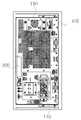
도 1은 본 발명의 일 실시예에 따른 탄화 방지 시스템이 구비된 RF Generator의 내부 구조를 개략적으로 나타낸 도면,
도 2는 본 발명의 일 실시예에 따른 탄화 방지 시스템이 구비된 RF Generator을 나타낸 정면도,
도 3은 본 발명의 일 실시예에 따른 탄화 방지 시스템이 구비된 RF Generator를 나타낸 구성 블록도
도 4는 본 발명의 일 실시예에 따른 탄화 방지 시스템의 센서모듈 회도로 및 센서모듈에서 측정한 측정값이 디스플레이 패널에 표시되는 상태 정보를 개략적으로 나타낸 도면이다.1 is a diagram schematically showing the internal structure of an RF Generator equipped with a carbonization prevention system according to an embodiment of the present invention;
2 is a front view showing an RF Generator equipped with a carbonization prevention system according to an embodiment of the present invention;
3 is a block diagram showing an RF Generator equipped with a carbonization prevention system according to an embodiment of the present invention;
4 is a schematic diagram of a sensor module circuit diagram of a carbonization prevention system according to an embodiment of the present invention and state information in which a measurement value measured by the sensor module is displayed on a display panel.
이하, 본 발명의 바람직한 실시예를 첨부된 도면들을 참조하여 상세히 설명한다. 우선 각 도면의 구성요소들에 참조 부호를 부가함에 있어서, 동일한 구성요소들에 대해서는 비록 다른 도면상에 표시되더라도 가능한 동일한 부호를 가지도록 하고 있음에 유의해야 한다. 또한, 본 발명을 설명함에 있어, 관련된 공지 구성 또는 기능에 대한 구체적인 설명이 본 발명의 요지를 흐릴 수 있다고 판단되는 경우에는 그 상세한 설명은 생략한다.Hereinafter, preferred embodiments of the present invention will be described in detail with reference to the accompanying drawings. First, in adding reference numerals to the components of each drawing, it should be noted that the same components are given the same reference numerals as possible even if they are indicated on different drawings. In addition, in describing the present invention, if it is determined that a detailed description of a related known configuration or function may obscure the gist of the present invention, the detailed description thereof will be omitted.
또한, 이하에서 기재된 "포함하다", "구성하다" 또는 "가지다" 등의 용어는, 특별히 반대되는 기재가 없는 한, 해당 구성 요소가 내재될 수 있음을 의미하는 것이므로, 다른 구성 요소를 제외하는 것이 아니라 다른 구성 요소를 더 포함할 수 있는 것으로 해석되어야 하며, 기술적이거나 과학적인 용어를 포함한 모든 용어들은, 다르게 정의되지 않는 한, 본 발명이 속하는 기술 분야에서 통상의 지식을 가진 자에 의해 일반적으로 이해되는 것과 동일한 의미를 가진다. 또한, 본 발명의 구성 요소를 설명하는 데 있어서, 제 1, 제 2, A, B, (a), (b) 등의 용어를 사용할 수 있다. 이러한 용어는 그 구성 요소를 다른 구성 요소와 구별하기 위한 것일 뿐, 그 용어에 의해 해당 구성 요소의 본질이나 차례 또는 순서 등이 한정되지 않는다. 어떤 구성 요소가 다른 구성요소에 "연결", "결합" 또는 "접속" 된다고 기재된 경우, 그 구성 요소는 그 다른 구성요소에 직접적으로 연결되거나 또는 접속될 수 있지만, 각 구성 요소 사이에 또 다른 구성 요소가 "연결", "결합" 또는 "접속"될 수도 있다고 이해되어야 할 것이다.In addition, terms such as "comprises", "comprises" or "have" described below mean that the corresponding component may be embedded, unless otherwise stated, excluding other components. It should be construed as being able to include other components rather than have the same meaning as understood. In addition, in describing the components of the present invention, terms such as first, second, A, B, (a), (b), etc. may be used. These terms are only for distinguishing the elements from other elements, and the essence, order, or order of the elements are not limited by the terms. When it is described that a component is “connected”, “coupled” or “connected” to another component, the component may be directly connected or connected to the other component, but another component between each component It should be understood that elements may be “connected,” “coupled,” or “connected.”
이하, 첨부된 도면을 참고하여 본 발명의 실시예들을 상세히 설명하도록 한다.Hereinafter, embodiments of the present invention will be described in detail with reference to the accompanying drawings.
도시된 바와 같이, 본 발명의 탄화 방지 시스템이 구비된 RF Generator는 케이싱(102), AC 공급부(110), 전원 공급 유닛(120), PA(Power Amp: 130), 커플러(140), 출력 커넥터(150), 컨트롤 보드(160), 센서모듈(210), MCU(220)를 포함하여 구성된다.As shown, the RF Generator equipped with the carbonization prevention system of the present invention is a
여기서, 케이싱(102)은 상기 각 구성요소들이 내장되게 구성되고, 작동 제어신호의 수신 여부에 따라 구동하는 흡기팬(104)이 후면부에 다수개로 구성된다.Here, the
또한, 케이싱(102)은 컨트롤 보드(160) 및 MCU(220)로부터 작동 제어신호를 수신받으며, 수신받은 작동 제어신호에 따라 상기 AC 공급부(110)를 정지시키는 인터락(Interlock: 106)이 구성된다.In addition, the
이때, 인터락(106)은 컨트롤 보드(160)와 MCU(220) 모두로부터 작동 제어신호가 수신되는 경우에 AC 전원 공급부(110)와 외부 전원 공급 장치 간의 연결을 해체하여 AC 전원이 공급되는 것을 차단함으로써, RF Generator가 작동하는 것을 장지시킬 수 있을 것이다.At this time, the
AC 전원 공급부(110)는 외부 전원과 연결되어 AC 전원의 공급이 이루어지도록 구성되는 것으로, 케이싱(102)의 전방측 하부 일면에 결합된다.The
이러한 AC 전원 공급부(110)는 컨트롤 보드(160)와 전기적 연결이 이루어지도록 구성되며, 컨트롤 보드(160)의 제어에 의해 공급받은 AC 전원을 전원 공급 유닛(120)측으로 공급한다.The
이와 같은 AC 전원 공급부(110)는 상기 인터락(106)의 제어에 의해 공급받은 외부 전원이 전원 공급 유닛(120)측으로 공급되는 것을 차단할 수 있도록 구성된다.The
전원 공급 유닛(120)은 케이싱(102)의 하부 공간에 배치되되, 컨트롤 보드(160)의 후방부 및 상부면에 배치되며, 컨트롤 보드(160)의 제어에 의해 AC 전원 공급부(110)로부터 AC 전원을 공급받아 DC 전원으로 변환하고, 변환환 DC 전원을 각 구성요소들로 공급하여 구동이 이루어질 수 있도록 함과 동시에 PA 앰프(130)로 공급하여 RF 신호에 대응하는 RF 출력 전력의 증폭이 이루어질 수 있도록 구성되는 것이다.The
이러한 전원 공급 유닛(120)은 케이싱(102)에 구성되는 흡기팬(104), 디스플레이 패널(240)과 연결되어 DC 전원의 공급이 이루어질 수 있도록 구성되며, 컨트롤 보드(160)의 제어를 통해 PA(130)와 전기적 연결이 이루어질 수 있도록 구성되어, 상기 PA(130)측으로 출력되는 DC 전원의 출력량에 대한 제어가 이루어지도록 구성된다.This
PA(Power Amp: 130)는 전원 공급 유닛(120)으로부터 출력되는 DC 전원이 입력되며, 입력된 DC 전원의 전력을 증폭시키고, 증폭된 DC 전원을 바탕으로 RF 출력 신호에 대한 RF 출력 전력의 증폭이 이루어질 수 있도록 구성되는 것이다.The PA (Power Amp: 130) receives DC power output from the
이러한 PA(130)는 본 발명에서 케이싱(102)의 내부 공간 중 상측 내부 공간에 배치되며, 특히 전원 공급 유닛(120)의 상부에 배치되어, 전원 공급 유닛(120)과 컨트롤 보드(160)와 각각 전기적 연결이 이루어지도록 구성된다.The PA 130 is disposed in the upper inner space of the inner space of the
또한, PA(130)는 증폭된 RF 출력 전력을 커플러(140)를 통과하여 RF 출력 커넥터(150)로 출력될 수 있도록 구성된다.In addition, the
여기서, 커플러(140)는 방향성 커플러(Directional Coupler) 일 수 있으며, PA(130)에서 출력되는 RF 출력 전력을 측정하고, 측정한 RF 출력 전력에 대한 값을 컨트롤 보드(160)로 전송하여 상기 RF 출력 전력에 대한 총 전력, 반사 손실 및 정재파비의 계산이 이루어질 수 있도록 구성된다.Here, the
이러한 커플러(140)는 PA(130)와 연결되는 입력포트와, RF 출력 커넥터(150)와 연결되는 출력포트로 구성되며, 상기 출력 포트로 출력되는 RF 출력 신호에 대한 RF 출력 전력의 측정이 이루어지도록 구성되고, 측정한 RF 출력 전력에 대한 반사 신호를 판독하여 컨트롤 보드(160)로 전송할 수 있다.The
RF 출력 커넥터(150)는 반도체 제조장치와 같은 설비와 연결되어 커플러(140)를 통과한 RF 출력 신호에 대한 RF 출력 전력을 상기 설비측으로 출력한다.The
컨트롤 보드(160)는 AC 공급부(110), 전원 공급 유닛(120), PA(130), 커플러(140) 및 출력 커넥터(150)와 전기적 연결이 이루어지며, 상기 각 구성요소들의 구동 여부를 제어하고, MCU(220)와 네트워크로 연결되어 이 MCU(220)로부터 전송되는 제어신호에 따라 AC 공급부(110) 및 전원 공급 유닛(120)의 구동 여부 및 온/오프 상태를 제어한다.The
이러한 컨트롤 보드(160)는 AC 전원 공급부(110)와 외부 전원 공급 장치와의 연결 여부에 대한 온/오프 제어가 이루어지도록 구성되는 것이고, 이 AC 전원 공급부(110)로부터 공급되는 AC 전원을 전원 공급 유닛(120)측으로 공급하는 것에 대한 제어가 가능하도록 구성되는 것이다.The
또한, 컨트롤 보드(160)는 전원 공급 유닛(120)측으로 공급되는 AC 전원의 공급량에 대한 제어가 이루어질 수 있도록 구성되며, PA(130)측으로 출력되는 DC 전원의 출력량에 대한 제어가 이루어질 수 있도록 구성된다.In addition, the
이때, 컨트롤 보드(160)는 DC 전원의 출력량을 제어함으로써, PA(130)을 통해 출력 전력에 대한 증폭이 이루어지도록 하고, 증폭된 DC 전원을 바탕으로 RF 출력 신호에 대한 증폭이 이루어질 수 있도록 하는 것이다.At this time, the
아울러, 컨트롤 보드(160)는 커플러(140)로부터 RF 출력 전력에 대한 측정값을 제공받고, 상기 측정값을 판독하여 상기 RF 출력 전력에 대한 총 전력, 반사 손실 및 정재파비값을 산출하고, 산출값에 따라 PA(130)로 출력되는 DC 전원의 출력량에 대한 제어가 이루어지도록 구성될 수 있다.In addition, the
한편, 컨트롤 보드(160)는 MCU(220)로부터 전송되는 제어신호에 작동 중지 신호가 포함되어 있는 경우, 컨트롤 보드(160)에 의해 구동이 제어되는 AC 공급부(110), 전원 공급 유닛(120), PA(130), 커플러(140)의 구동을 모두 정지시키며, 동시에 정지될 수 있도록 제어함으로써, 상기 MCU(220)로부터 RF Generator가 탄화에 의해 상기 AC 공급부(110), 전원 공급 유닛(120), PA(130), 커플러(140)를 포함하는 각 구성요소들에 가해지는 데미지를 줄일 수 있으며, 상기 탄화에 의한 화재가 발생하는 것을 차단할 수 있도록 구성되는 것이다.On the other hand, when the
이때, 컨트롤 보드(160)는 상기 작동 중지 신호가 포함되어 있는 경우, AC 전원 공급부(110)의 작동을 차단시키는 작동 제어신호를 생성하여 인터락(106)으로 전송할 수 있다.At this time, when the operation stop signal is included, the
또한, 컨트롤 보드(160)는 MCU(220)로부터 전송되는 제어신호에 흡기팬(104)의 구동 제어신호가 포함되어 있는 경우, 상기 흡기팬(104)의 구동 여부 및 구동 세기에 대한 제어가 이루어지도록 구성될 수 있으며, 이에 따라 RF Generator의 케이싱(102) 내부에 감지된 연기를 케이싱(102)의 외부로 배출시키도록 구성될 수 있다.In addition, when the control signal transmitted from the
한편, 본 발명의 RF Generator는 RF Generator의 케이싱(102) 내부에 장착되어 RF Generator의 내부에서 탄화 초기 열화발생으로 인한 연기가 발생하는 경우, 이를 감지하여 컨트롤 보드(160)로 작동 정지에 대한 제어신호를 전송함으로써, RF Generator의 탄화로 인한 화재가 발생하는 것을 미연에 방지할 수 있는 탄화 방지 시스템(200)이 더 구성된다.On the other hand, the RF generator of the present invention is mounted inside the
탄화 방지 시스템(200)은 상기 RF Generator의 케이싱(102) 내부에 대한 연기의 발생 여부를 감지하고, 이 RF Generator의 케이싱(102) 내부 온도 및 습도를 감지하여 전송하는 센서모듈(210)과, 상기 센서모듈(210)과 네트워크로 연결되며, 이 센서모듈(210)로부터 전송되는 감지 데이터를 분석하여 RF Generator의 작동 차단 여부 및 경고 메세지의 송출 여부에 대한 제어신호를 생성하여 전송하는 MCU(Micro Controller Unit: 220), 탄화 발생시 MCU(220)의 제어에 따라 경고음을 출력시켜 화재 발생에 따른 대처를 신속하게 수행할 수 있도록 하는 경고 알람부(230) 및 센서모듈(210)에서 측정한 RF Generator의 실시간 내부 연기량, 온도 및 습도에 대한 정보를 실시간 출력하고, 상기 제어신호 송출 여부에 대한 기준 데이터를 설정하는 디스플레이 패널(240)을 포함하여 구성된다.The
센서모듈(210)은 RF Generator의 케이싱(102) 내부에서 연기가 발생하는지 여부를 감지하고, 연기의 발생 여부에 대한 감지 신호를 MCU(220)로 전송하는 연기 감지 센서(212)와, RF Generator의 케이싱(102) 내부의 온도를 측정하고, 측정한 온도정보를 MCU(220)로 전송하는 온도센서(214)와, RF Generator의 케이싱(102) 내부의 습도를 측정하고, 측정한 습도정보를 MCU(220)로 전송하는 습도센서(216)를 포함하여 구성된다.The
여기서, 연기 감지 센서(212)는 연기가 감지되는 경우, 감지된 연기의 연기량에 대한 측정이 이루어지도록 구성되며, 연기의 발생 여부 및 연기량 측정값에 대한 정보를 MCU(220)로 전송할 수 있다.Here, the
이때, 연기의 발생이 감지되는 경우, 실시간으로 감지된 연기의 연기량을 측정할 수 있으며, 측정한 연기량에 대한 정보를 MCU(220)로 전송할 수 있다.In this case, when generation of smoke is detected, the amount of smoke sensed in real time may be measured, and information on the measured amount of smoke may be transmitted to the
또한, 온도센서(214)와 습도센서(216) 역시 RF Generator의 케이싱(102) 내부에 대한 온도 및 습도 정보를 실시간 전송할 수 있다.In addition, the
한편, 본 발명의 센서모듈(210)은 RF Generator의 케이싱(102) 내부에 수분이 존재하는지 여부를 감지하고, 수분이 존재하는 경우, 이 수분에 대한 수분량을 측정하여 수분 측정값을 생성하고, 생성한 수분 측정값을 MCU(220)로 전송하는 수분 감지 센서를 더 포함할 수 있다.On the other hand, the
여기서, 수분 감지 센서는 통상의 워터 리크 센서로 이루어질 수 있으며, 습도센서(216)로부터 전송되는 습도 정보에 따라 MCU(220)의 제어를 통해 선택적으로 구동이 이루어질 수 있다.Here, the moisture detection sensor may be a conventional water leak sensor, and may be selectively driven through the control of the
즉, 수분 감지 센서는, 상기 습도센서(216)로부터 전송되는 습도가 디스플레이 패널(240)의 조작을 통해 설정된 습도 설정값 보다 큰 값으로 이루어지는 경우에만 MCU(220)의 제어를 통해 구동이 이루어지도록 구성되는 것이다.That is, the moisture detection sensor is driven through the control of the
MCU(Micro Controller Unit: 220)는 센서모듈(210), 컨트롤 보드(160) 및 인터락(106)과 네트워크로 연결되며, 센서모듈(210)로부터 전송되는 데이터를 판독하여 컨트롤 보드(160)로 전송하는 제어신호와 인터락(106)으로 전송하는 작동 제어신호를 생성하고, 상기 제어신호 및 작동 제어신호의 생성시 경고 알람부(230)의 작동을 제어하며, 디스플레이 패널(240)을 통해 입력되는 기준 데이터를 바탕으로 상기 제어신호 및 작동 제어신호의 생성 조건값을 설정하는 구성요소이다.MCU (Micro Controller Unit: 220) is connected to the network with the
MCU(220)는, 센서모듈(210)과 실시간으로 통신이 이루어지도록 구성되며, 디스플레이 패널(240)로부터 전송되는 기준 데이터를 판독하여 상기 기준 데이터에 포함된 연기량 기준값, 온도 기준값 및 습도 기준값을 설정하고, 설정된 기준값으로 이루어지는 생성 조건값을 생성한다.The
이러한 MCU(220)는, 센서모듈(210)로부터 전송되는 데이터들, 즉 연기 감지 센서(212)를 통해 수신받은 연기의 발생 여부 및 연기량 측정값과, 온도센서(214)와 습도센서(216)를 통해 각각 수신받은 온도 정보 및 습도 정보가 상기 생성 조건값을 초과하는지 여부를 판단하고, 상기 데이터들이 생성 조건값을 초과하는 경우에만 제어신호 및 작동 제어신호를 생성하여 컨트롤 보드(160)와 인터락(106)으로 전송함으로써, RF Generator의 내부 화재가 발생하는 것을 미연에 방지하는 것이다.The
이때, MCU(220)는 상기 제어신호 및 작동 제어신호의 생성이 이루어지는 경우, 경고 알람부(230)의 구동이 이루어지도록 제어한다.In this case, when the control signal and the operation control signal are generated, the
여기서, 상기 경고 알람부(230)는 LED, 또는 스피커 등으로 구성되어 점멸에 의한 경고, 또는 음성이나 소리에 의한 경고가 이루어질 수 있도록 구성될 수 있으나, 이에 한정하는 것은 아니다.Here, the
아울러, 본 발명의 MCU(220)는, RF Generator의 최초 구동시 센서모듈(210)의 구동을 제어하며, 상기 센서모듈(210)로부터 전송되는 최초 데이터를 저장할 수 있고, 저장한 최초 데이터와 상기 센서모듈(210)에서 전송하는 실시간 데이터를 대비하여 연기 발생 여부 및 연기량 측정값, 온도 및 습도 정보의 변화량에 대한 변화량 데이터를 생성할 수 있다.In addition, the
이때, MCU(220)는, 생성한 변화량 데이터가 허용 범위를 초과하는 경우, 작동 제어신호를 생성하여 인터락(106)으로 전송하고, 경고 알람부(230)가 구동할 수 있도록 제어할 수 있다.At this time, when the generated variation data exceeds the allowable range, the
여기서, 상기 허용 범위는 생성 조건값의 10% 이상의 범위로 이루어질 수 있으며, 본 발명에서의 MCU(220)는, 상기 변화량 데이터의 변화량이 생성 조건값의 10% 이상의 값으로 이루어지는 경우, 화재 발생 위험이 있는 것으로 판단하여 작동 제어신호를 생성하여 전송할 수 있을 것이다.Here, the allowable range may be in the range of 10% or more of the generation condition value, and the
하지만, 이에 한정하는 것은 아니며, 상기 허용 범위는 RF Generator의 크기에 따라 다르게 적용될 수 있음은 물론이다.However, the present invention is not limited thereto, and of course, the allowable range may be applied differently depending on the size of the RF generator.
이상의 설명은 본 발명의 기술 사상을 예시적으로 설명한 것에 불과한 것으로서, 본 발명이 속하는 기술 분야에서 통상의 지식을 가진 자라면 본 발명의 본질적인 특성에서 벗어나지 않는 범위에서 다양한 수정 및 변형이 가능할 것이다. 따라서, 본 발명에 개시된 실시예들은 본 발명의 기술 사상을 한정하기 위한 것이 아니라 설명하기 위한 것이고, 이러한 실시예에 의하여 본 발명의 기술 사상의 범위가 한정되는 것은 아니다. 본 발명의 보호 범위는 아래의 청구범위에 의하여 해석되어야 하며, 그와 동등한 범위 내에 있는 모든 기술 사상은 본 발명의 권리범위에 포함되는 것으로 해석되어야 할 것이다.The above description is merely illustrative of the technical spirit of the present invention, and various modifications and variations will be possible without departing from the essential characteristics of the present invention by those skilled in the art to which the present invention pertains. Therefore, the embodiments disclosed in the present invention are not intended to limit the technical spirit of the present invention, but to explain, and the scope of the technical spirit of the present invention is not limited by these embodiments. The protection scope of the present invention should be construed by the following claims, and all technical ideas within the equivalent range should be construed as being included in the scope of the present invention.
102: 케이싱
104: 흡기팬
106: 인터락
110: AC 전원 공급부
120: 전원 공급 유닛
130: PA
140: 커플러
150: 출력 커넥터
160: 컨트롤 보드
200: 탄화 방지 시스템
210: 센서모듈
220: MCU
230: 경고 알람부
240: 디스플레이 패널102: casing
104: intake fan
106: interlock
110: AC power supply
120: power supply unit
130: PA
140: coupler
150: output connector
160: control board
200: carbonization prevention system
210: sensor module
220: MCU
230: warning alarm unit
240: display panel
Claims (7)
Translated fromKorean상기 케이싱(102)에 장착되며, AC 전원을 공급받아 출력하는 AC 전원 공급부(110);
상기 AC 전원 공급부(110)로부터 상기 AC 전원을 공급받아 DC 전원으로 변환하고, 변환환 DC 전원을 출력하는 전원 공급 유닛(120);
상기 케이싱(102)의 내부 상측 공간에 구성되고, 상기 전원 공급 유닛(120)으로부터 상기 DC 전원을 공급받아 RF 출력 신호에 대한 RF 출력 전력을 증폭시켜 출력하는 PA(Power Amp: 130);
상기 PA(130)와 연결되어 상기 RF 출력 전력을 출력하는 RF 출력 커넥터(150);
상기 PA(130)와 RF 출력 커넥터(150) 사이에 구성되며, 출력되는 RF 출력 전력을 측정하고, 측정한 RF 출력 전력에 대한 측정값을 전송하는 커플러(140);
상기 커플러(140)로부터 상기 RF 출력 전력 측정값을 수신받아 상기 RF 출력 전력에 대한 총 전력, 반사 손실 및 정재파비값을 산출하고, 산출값에 따라 PA(130)로 출력되는 DC 전원의 출력량을 제어하는 컨트롤 보드(160);
상기 케이싱(102) 내부에서 발생하는 연기를 감지하고, 상기 케이싱(102)의 내부 온도 및 습도를 측정하여 판독하고, 판독 결과에 따라 컨트롤 보드(160)로 전송하는 제어신호와 인터락(106)으로 전송하는 작동 제어신호를 생성 및 전송하는 탄화 방지 시스템(200);을 포함하며,
상기 인터락(106)은 상기 컨트롤 보드(160)와 탄화 방지 시스템(200) 모두로부터 작동 제어신호가 수신되는 경우, 상기 AC 전원 공급부(110)의 작동을 차단하는 것을 특징으로 하는 탄화 방지 시스템이 구비된 RF Generator.
a casing 102 to which the intake fan 104 and the interlock 106 are mounted;
an AC power supply unit 110 mounted on the casing 102 and receiving and outputting AC power;
a power supply unit 120 that receives the AC power from the AC power supply unit 110 and converts it into DC power and outputs converted DC power;
a PA (Power Amp: 130) configured in the inner upper space of the casing 102 and receiving the DC power from the power supply unit 120 to amplify and output RF output power for an RF output signal;
an RF output connector 150 connected to the PA 130 to output the RF output power;
a coupler 140 configured between the PA 130 and the RF output connector 150, measuring the output RF output power, and transmitting a measurement value for the measured RF output power;
Receives the RF output power measurement value from the coupler 140 , calculates total power, return loss, and standing wave ratio values for the RF output power, and controls the output amount of DC power output to the PA 130 according to the calculated values to the control board 160;
Detects smoke generated inside the casing 102, measures and reads the internal temperature and humidity of the casing 102, and a control signal and interlock 106 transmitted to the control board 160 according to the reading result Including;
The interlock 106 is a carbonization prevention system, characterized in that when an operation control signal is received from both the control board 160 and the carbonization prevention system 200, the operation of the AC power supply unit 110 is blocked. Equipped RF Generator.
상기 탄화 방지 시스템(200)은,
상기 케이싱(102) 내부에 대한 연기의 발생 여부 및 연기량, 내부 온도 및 습도를 감지하여 전송하는 센서모듈(210);
상기 센서모듈(210)로부터 전송되는 감지 데이터를 분석하여 RF Generator의 작동 차단 여부 및 경고 메세지의 송출 여부에 대한 제어신호를 생성하여 전송하는 MCU(Micro Controller Unit: 220);
상기 탄화 발생시 MCU(220)의 제어에 따라 경고음을 출력하는 경고 알람부(230); 및
상기 케이싱(102)의 실시간 내부 연기량, 온도 및 습도에 대한 정보를 실시간 출력하고, 상기 제어신호 송출 여부에 대한 기준 데이터를 설정하는 디스플레이 패널(240);
을 포함하는 것을 특징으로 하는 탄화 방지 시스템이 구비된 RF Generator.
According to claim 1,
The carbonization prevention system 200,
a sensor module 210 for detecting and transmitting whether or not smoke is generated inside the casing 102, the amount of smoke, and internal temperature and humidity;
MCU (Micro Controller Unit: 220) that analyzes the sensed data transmitted from the sensor module 210 to generate and transmit a control signal for whether to block the operation of the RF generator and whether to transmit a warning message;
a warning alarm unit 230 for outputting a warning sound according to the control of the MCU 220 when the carbonization occurs; and
a display panel 240 for outputting real-time information on the real-time internal smoke amount, temperature and humidity of the casing 102, and setting reference data for whether the control signal is transmitted;
RF Generator equipped with a carbonization prevention system comprising a.
상기 센서모듈(210)은,
상기 케이싱(102) 내부에서 연기가 발생하는지 여부를 감지하고, 연기의 발생 여부에 대한 감지 신호를 상기 MCU(220)로 전송하는 연기 감지 센서(212)와,
상기 케이싱(102) 내부의 온도를 측정하고, 측정한 온도정보를 상기 MCU(220)로 전송하는 온도센서(214)와,
상기 케이싱(102) 내부의 습도를 측정하고, 측정한 습도정보를 상기 MCU(220)로 전송하는 습도센서(216)
를 포함하는 것을 특징으로 하는 탄화 방지 시스템이 구비된 RF Generator.
3. The method of claim 2,
The sensor module 210,
A smoke detection sensor 212 that detects whether smoke is generated inside the casing 102 and transmits a detection signal as to whether or not smoke is generated to the MCU 220;
a temperature sensor 214 that measures the temperature inside the casing 102 and transmits the measured temperature information to the MCU 220;
A humidity sensor 216 that measures the humidity inside the casing 102 and transmits the measured humidity information to the MCU 220 .
RF Generator equipped with a carbonization prevention system comprising a.
상기 센서모듈(210)은,
상기 케이싱(102) 내부에 수분이 존재하는지 여부를 감지하고, 수분이 존재하는 경우, 상기 수분에 대한 수분량을 측정하여 수분 측정값을 생성하고, 생성한 수분 측정값을 상기 MCU(220)로 전송하는 수분 감지 센서를 더 포함하는 것을 특징으로 하는 탄화 방지 시스템이 구비된 RF Generator.
4. The method of claim 3,
The sensor module 210,
Detects whether moisture exists inside the casing 102 , and if there is moisture, measures the amount of moisture for the moisture to generate a moisture measurement value, and transmits the generated moisture measurement value to the MCU 220 . RF Generator equipped with a carbonization prevention system, characterized in that it further comprises a moisture detection sensor.
상기 MCU(220)는,
상기 디스플레이 패널(240)로부터 전송되는 기준 데이터를 판독하여 생성 조건값을 생성하며, 상기 생성 조건값과 상기 센서모듈(210)로부터 전송되는 데이터들을 비교하여 상기 센서모듈(210)의 데이터가 상기 생성 조건값을 초과하는지 여부를 판단하고, 상기 데이터들이 생성 조건값을 초과하는 경우에만 제어신호 및 작동 제어신호를 생성하여 상기 컨트롤 보드(160)와 인터락(106)으로 전송하는 것을 특징으로 하는 탄화 방지 시스템이 구비된 RF Generator.
5. The method of claim 4,
The MCU 220,
A generation condition value is generated by reading reference data transmitted from the display panel 240 , and data of the sensor module 210 is generated by comparing the generation condition value with data transmitted from the sensor module 210 . It is determined whether the condition value is exceeded, and only when the data exceeds the generation condition value, a control signal and an operation control signal are generated and transmitted to the control board 160 and the interlock 106 . RF Generator with protection system.
상기 MCU(220)는,
상기 센서모듈(210)로부터 전송되는 최초 데이터와 상기 센서모듈(210)에서 전송하는 실시간 데이터를 대비하여 연기 발생 여부 및 연기량 측정값, 온도 및 습도 정보의 변화량에 대한 변화량 데이터를 생성하며, 생성한 변화량 데이터가 허용 범위를 초과하는 경우, 작동 제어신호를 생성하여 상기 인터락(106)으로 전송하고, 경고 알람부(230)가 구동할 수 있도록 제어하는 것을 특징으로 하는 탄화 방지 시스템이 구비된 RF Generator.
6. The method of claim 5,
The MCU 220,
By comparing the initial data transmitted from the sensor module 210 and the real-time data transmitted from the sensor module 210, the amount of change data for whether smoke is generated and the amount of smoke measured, and the amount of change in temperature and humidity information is generated, When the amount of change data exceeds the allowable range, an operation control signal is generated and transmitted to the interlock 106 and the warning alarm unit 230 is equipped with a carbonization prevention system, characterized in that it controls to be driven RF Generator.
상기 허용 범위는 상기 생성 조건값의 10% 이상의 범위로 이루어지는 것을 특징으로 하는 탄화 방지 시스템이 구비된 RF Generator.
7. The method of claim 6,
The allowable range is an RF Generator with a carbonization prevention system, characterized in that it consists of a range of 10% or more of the generation condition value.
Priority Applications (2)
| Application Number | Priority Date | Filing Date | Title |
|---|---|---|---|
| KR1020220055427AKR102450733B1 (en) | 2022-05-04 | 2022-05-04 | RF Generator with Carbonization Prevention System |
| US18/139,639US20230360881A1 (en) | 2022-05-04 | 2023-04-26 | Rf generator with carbonization prevention system |
Applications Claiming Priority (1)
| Application Number | Priority Date | Filing Date | Title |
|---|---|---|---|
| KR1020220055427AKR102450733B1 (en) | 2022-05-04 | 2022-05-04 | RF Generator with Carbonization Prevention System |
Publications (1)
| Publication Number | Publication Date |
|---|---|
| KR102450733B1true KR102450733B1 (en) | 2022-10-06 |
Family
ID=83597463
Family Applications (1)
| Application Number | Title | Priority Date | Filing Date |
|---|---|---|---|
| KR1020220055427AActiveKR102450733B1 (en) | 2022-05-04 | 2022-05-04 | RF Generator with Carbonization Prevention System |
Country Status (2)
| Country | Link |
|---|---|
| US (1) | US20230360881A1 (en) |
| KR (1) | KR102450733B1 (en) |
Citations (4)
| Publication number | Priority date | Publication date | Assignee | Title |
|---|---|---|---|---|
| KR200420965Y1 (en) | 2006-04-24 | 2006-07-07 | 주식회사 영신알에프 | Matching network integrated high frequency generator |
| KR101035248B1 (en)* | 2007-09-10 | 2011-05-18 | 도쿄엘렉트론가부시키가이샤 | Plasma processing apparatus, plasma processing method and storage medium |
| JP2017221656A (en)* | 2016-05-19 | 2017-12-21 | コヴィディエン リミテッド パートナーシップ | Modular microwave generators and methods for operating modular microwave generators |
| KR20190103804A (en)* | 2018-02-28 | 2019-09-05 | 주식회사 뉴파워 프라즈마 | High frequency power generator with hybrid heat sink structures for plasma processing apparatus |
- 2022
- 2022-05-04KRKR1020220055427Apatent/KR102450733B1/enactiveActive
- 2023
- 2023-04-26USUS18/139,639patent/US20230360881A1/enactivePending
Patent Citations (4)
| Publication number | Priority date | Publication date | Assignee | Title |
|---|---|---|---|---|
| KR200420965Y1 (en) | 2006-04-24 | 2006-07-07 | 주식회사 영신알에프 | Matching network integrated high frequency generator |
| KR101035248B1 (en)* | 2007-09-10 | 2011-05-18 | 도쿄엘렉트론가부시키가이샤 | Plasma processing apparatus, plasma processing method and storage medium |
| JP2017221656A (en)* | 2016-05-19 | 2017-12-21 | コヴィディエン リミテッド パートナーシップ | Modular microwave generators and methods for operating modular microwave generators |
| KR20190103804A (en)* | 2018-02-28 | 2019-09-05 | 주식회사 뉴파워 프라즈마 | High frequency power generator with hybrid heat sink structures for plasma processing apparatus |
Also Published As
| Publication number | Publication date |
|---|---|
| US20230360881A1 (en) | 2023-11-09 |
Similar Documents
| Publication | Publication Date | Title |
|---|---|---|
| KR101519923B1 (en) | A partial discharge detection system for a distributing board with the acoustic emission sensor | |
| CN114397093B (en) | A fiber laser power monitoring system and safety interlocking method | |
| WO2004077022A3 (en) | Methods and apparatus for calibration and metrology for an integrated rf generator system | |
| TW201725939A (en) | Methods and apparatus for synchronizing RF pulses in a plasma processing system | |
| CN102193855A (en) | Abnormity alarm circuit for fan | |
| KR102450733B1 (en) | RF Generator with Carbonization Prevention System | |
| CN103875056A (en) | Method and apparatus for protecting passive components connected to a radio-frequency generator | |
| CN105915288B (en) | A kind of Polarization Dependent Loss compensation system based on Raman amplifiction effect | |
| CN110763959A (en) | High-voltage switch cabinet partial discharge detection circuit and detection method thereof | |
| CN209844923U (en) | A solid state power amplifier | |
| CN203323878U (en) | On-line temperature monitoring apparatus for plugging bus joint | |
| US8260219B2 (en) | Network communication device and method for detecting abnormal load | |
| CN110632533A (en) | Power detection system of RF (radio frequency) power supply | |
| CN206989268U (en) | A kind of gas cooker safety device | |
| CN105119136B (en) | Raman optical fiber amplifier with differential loss detection function and optical fiber differential loss detection method thereof | |
| KR101901846B1 (en) | Power outlet device having apparatus of consumption power | |
| CN107918089B (en) | Circuit and method for partial discharge detection | |
| KR200457049Y1 (en) | Monitoring device for semiconductor manufacturing equipment | |
| CN115052239A (en) | Audio power amplifier public address detecting system | |
| CN108667474A (en) | A communication solar signal switching and amplifying device and using method | |
| CN209342813U (en) | Earth resistance tester | |
| KR101061676B1 (en) | Standby power interruption and its unblocking system and method | |
| CN220231894U (en) | Detection device for generating ozone by partial discharge of generator stator | |
| CN109639247A (en) | The monitor control system and method for the output power of radio-frequency power amplifier | |
| CN222545789U (en) | Electrical fire safety equipment |
Legal Events
| Date | Code | Title | Description |
|---|---|---|---|
| PA0109 | Patent application | St.27 status event code:A-0-1-A10-A12-nap-PA0109 | |
| PA0201 | Request for examination | St.27 status event code:A-1-2-D10-D11-exm-PA0201 | |
| PA0302 | Request for accelerated examination | St.27 status event code:A-1-2-D10-D17-exm-PA0302 St.27 status event code:A-1-2-D10-D16-exm-PA0302 | |
| D13-X000 | Search requested | St.27 status event code:A-1-2-D10-D13-srh-X000 | |
| D14-X000 | Search report completed | St.27 status event code:A-1-2-D10-D14-srh-X000 | |
| E902 | Notification of reason for refusal | ||
| PE0902 | Notice of grounds for rejection | St.27 status event code:A-1-2-D10-D21-exm-PE0902 | |
| P11-X000 | Amendment of application requested | St.27 status event code:A-2-2-P10-P11-nap-X000 | |
| P13-X000 | Application amended | St.27 status event code:A-2-2-P10-P13-nap-X000 | |
| E701 | Decision to grant or registration of patent right | ||
| PE0701 | Decision of registration | St.27 status event code:A-1-2-D10-D22-exm-PE0701 | |
| GRNT | Written decision to grant | ||
| PR0701 | Registration of establishment | St.27 status event code:A-2-4-F10-F11-exm-PR0701 | |
| PR1002 | Payment of registration fee | St.27 status event code:A-2-2-U10-U11-oth-PR1002 Fee payment year number:1 | |
| PG1601 | Publication of registration | St.27 status event code:A-4-4-Q10-Q13-nap-PG1601 | |
| P14-X000 | Amendment of ip right document requested | St.27 status event code:A-5-5-P10-P14-nap-X000 | |
| PN2301 | Change of applicant | St.27 status event code:A-5-5-R10-R11-asn-PN2301 | |
| P16-X000 | Ip right document amended | St.27 status event code:A-5-5-P10-P16-nap-X000 | |
| PN2301 | Change of applicant | St.27 status event code:A-5-5-R10-R14-asn-PN2301 | |
| R18-X000 | Changes to party contact information recorded | St.27 status event code:A-5-5-R10-R18-oth-X000 | |
| PR1001 | Payment of annual fee | St.27 status event code:A-4-4-U10-U11-oth-PR1001 Fee payment year number:4 |