KR102450514B1 - Operation method of memory controller and operation method of storage device including the same - Google Patents
Operation method of memory controller and operation method of storage device including the sameDownload PDFInfo
- Publication number
- KR102450514B1 KR102450514B1KR1020170120594AKR20170120594AKR102450514B1KR 102450514 B1KR102450514 B1KR 102450514B1KR 1020170120594 AKR1020170120594 AKR 1020170120594AKR 20170120594 AKR20170120594 AKR 20170120594AKR 102450514 B1KR102450514 B1KR 102450514B1
- Authority
- KR
- South Korea
- Prior art keywords
- delay time
- write buffer
- buffer
- size
- write
- Prior art date
- Legal status (The legal status is an assumption and is not a legal conclusion. Google has not performed a legal analysis and makes no representation as to the accuracy of the status listed.)
- Active
Links
Images


Classifications
- G—PHYSICS
- G06—COMPUTING OR CALCULATING; COUNTING
- G06F—ELECTRIC DIGITAL DATA PROCESSING
- G06F13/00—Interconnection of, or transfer of information or other signals between, memories, input/output devices or central processing units
- G06F13/14—Handling requests for interconnection or transfer
- G06F13/16—Handling requests for interconnection or transfer for access to memory bus
- G06F13/1668—Details of memory controller
- G06F13/1673—Details of memory controller using buffers
- G—PHYSICS
- G06—COMPUTING OR CALCULATING; COUNTING
- G06F—ELECTRIC DIGITAL DATA PROCESSING
- G06F12/00—Accessing, addressing or allocating within memory systems or architectures
- G06F12/02—Addressing or allocation; Relocation
- G06F12/08—Addressing or allocation; Relocation in hierarchically structured memory systems, e.g. virtual memory systems
- G06F12/0802—Addressing of a memory level in which the access to the desired data or data block requires associative addressing means, e.g. caches
- G06F12/0806—Multiuser, multiprocessor or multiprocessing cache systems
- G06F12/0811—Multiuser, multiprocessor or multiprocessing cache systems with multilevel cache hierarchies
- G—PHYSICS
- G06—COMPUTING OR CALCULATING; COUNTING
- G06F—ELECTRIC DIGITAL DATA PROCESSING
- G06F13/00—Interconnection of, or transfer of information or other signals between, memories, input/output devices or central processing units
- G06F13/14—Handling requests for interconnection or transfer
- G06F13/16—Handling requests for interconnection or transfer for access to memory bus
- G06F13/1605—Handling requests for interconnection or transfer for access to memory bus based on arbitration
- G06F13/161—Handling requests for interconnection or transfer for access to memory bus based on arbitration with latency improvement
- G—PHYSICS
- G06—COMPUTING OR CALCULATING; COUNTING
- G06F—ELECTRIC DIGITAL DATA PROCESSING
- G06F3/00—Input arrangements for transferring data to be processed into a form capable of being handled by the computer; Output arrangements for transferring data from processing unit to output unit, e.g. interface arrangements
- G06F3/06—Digital input from, or digital output to, record carriers, e.g. RAID, emulated record carriers or networked record carriers
- G06F3/0601—Interfaces specially adapted for storage systems
- G06F3/0602—Interfaces specially adapted for storage systems specifically adapted to achieve a particular effect
- G06F3/061—Improving I/O performance
- G06F3/0611—Improving I/O performance in relation to response time
- G—PHYSICS
- G06—COMPUTING OR CALCULATING; COUNTING
- G06F—ELECTRIC DIGITAL DATA PROCESSING
- G06F3/00—Input arrangements for transferring data to be processed into a form capable of being handled by the computer; Output arrangements for transferring data from processing unit to output unit, e.g. interface arrangements
- G06F3/06—Digital input from, or digital output to, record carriers, e.g. RAID, emulated record carriers or networked record carriers
- G06F3/0601—Interfaces specially adapted for storage systems
- G06F3/0628—Interfaces specially adapted for storage systems making use of a particular technique
- G06F3/0655—Vertical data movement, i.e. input-output transfer; data movement between one or more hosts and one or more storage devices
- G06F3/0656—Data buffering arrangements
- G—PHYSICS
- G06—COMPUTING OR CALCULATING; COUNTING
- G06F—ELECTRIC DIGITAL DATA PROCESSING
- G06F3/00—Input arrangements for transferring data to be processed into a form capable of being handled by the computer; Output arrangements for transferring data from processing unit to output unit, e.g. interface arrangements
- G06F3/06—Digital input from, or digital output to, record carriers, e.g. RAID, emulated record carriers or networked record carriers
- G06F3/0601—Interfaces specially adapted for storage systems
- G06F3/0628—Interfaces specially adapted for storage systems making use of a particular technique
- G06F3/0655—Vertical data movement, i.e. input-output transfer; data movement between one or more hosts and one or more storage devices
- G06F3/0659—Command handling arrangements, e.g. command buffers, queues, command scheduling
- G—PHYSICS
- G06—COMPUTING OR CALCULATING; COUNTING
- G06F—ELECTRIC DIGITAL DATA PROCESSING
- G06F3/00—Input arrangements for transferring data to be processed into a form capable of being handled by the computer; Output arrangements for transferring data from processing unit to output unit, e.g. interface arrangements
- G06F3/06—Digital input from, or digital output to, record carriers, e.g. RAID, emulated record carriers or networked record carriers
- G06F3/0601—Interfaces specially adapted for storage systems
- G06F3/0668—Interfaces specially adapted for storage systems adopting a particular infrastructure
- G06F3/0671—In-line storage system
- G06F3/0673—Single storage device
- G06F3/0679—Non-volatile semiconductor memory device, e.g. flash memory, one time programmable memory [OTP]
- G—PHYSICS
- G11—INFORMATION STORAGE
- G11C—STATIC STORES
- G11C16/00—Erasable programmable read-only memories
- G11C16/02—Erasable programmable read-only memories electrically programmable
- G11C16/06—Auxiliary circuits, e.g. for writing into memory
- G11C16/10—Programming or data input circuits
- G—PHYSICS
- G11—INFORMATION STORAGE
- G11C—STATIC STORES
- G11C16/00—Erasable programmable read-only memories
- G11C16/02—Erasable programmable read-only memories electrically programmable
- G11C16/06—Auxiliary circuits, e.g. for writing into memory
- G11C16/32—Timing circuits
- G—PHYSICS
- G06—COMPUTING OR CALCULATING; COUNTING
- G06F—ELECTRIC DIGITAL DATA PROCESSING
- G06F2212/00—Indexing scheme relating to accessing, addressing or allocation within memory systems or architectures
- G06F2212/10—Providing a specific technical effect
- G06F2212/1016—Performance improvement
- G06F2212/1024—Latency reduction
- G—PHYSICS
- G06—COMPUTING OR CALCULATING; COUNTING
- G06F—ELECTRIC DIGITAL DATA PROCESSING
- G06F2212/00—Indexing scheme relating to accessing, addressing or allocation within memory systems or architectures
- G06F2212/20—Employing a main memory using a specific memory technology
- G06F2212/202—Non-volatile memory
- G06F2212/2022—Flash memory
Landscapes
- Engineering & Computer Science (AREA)
- Theoretical Computer Science (AREA)
- Physics & Mathematics (AREA)
- General Engineering & Computer Science (AREA)
- General Physics & Mathematics (AREA)
- Human Computer Interaction (AREA)
- Techniques For Improving Reliability Of Storages (AREA)
- Memory System (AREA)
Abstract
Translated fromKorean
Description
Translated fromKorean본 발명은 저장 장치에 관한 것으로, 좀 더 상세하게는 메모리 컨트롤러의 동작 방법 및 그것을 포함하는 저장 장치의 동작 방법 에 관한 것이다.The present invention relates to a storage device, and more particularly, to a method of operating a memory controller and a method of operating a storage device including the same.
반도체 메모리는 SRAM (Static RAM), DRAM (Dynamic RAM), SDRAM (Synchronous DRAM) 등과 같이 전원 공급이 차단되면 저장하고 있던 데이터가 소멸되는 휘발성 메모리 장치 및 ROM (Read Only Memory), PROM (Programmable ROM), EPROM (Electrically Programmable ROM), EEPROM (Electrically Erasable and Programmable ROM), 플래시 메모리 장치, PRAM (Phase-change RAM), MRAM (Magnetic RAM), RRAM (Resistive RAM), FRAM (Ferroelectric RAM) 등과 같이 전원 공급이 차단되어도 저장하고 있던 데이터를 유지하는 불휘발성 메모리 장치로 구분된다.Semiconductor memory includes volatile memory devices such as SRAM (Static RAM), DRAM (Dynamic RAM), SDRAM (Synchronous DRAM), etc., in which the stored data is destroyed when the power supply is cut off, as well as ROM (Read Only Memory) and PROM (Programmable ROM). , EPROM (Electrically Programmable ROM), EEPROM (Electrically Erasable and Programmable ROM), flash memory device, PRAM (Phase-change RAM), MRAM (Magnetic RAM), RRAM (Resistive RAM), FRAM (Ferroelectric RAM), etc. It is classified as a non-volatile memory device that retains the stored data even when it is blocked.
최근에는 플래시 메모리 기반의 저장 장치의 성능을 향상시키기 위한 다양한 기법들이 사용되고 있다. 일 예로서, 저장 장치는 호스트로부터 수신된 쓰기 데이터를 별도의 버퍼 메모리에 저장하고, 호스트로 저장이 완료되었음을 알린다. 이후에, 저장 장치는 버퍼 메모리에 저장된 쓰기 데이터를 플래시 메모리에 프로그램한다. 상술된 바와 같이, 저장 장치는 다양한 자원들(예를 들어, 버퍼 메모리)을 사용하여 성능을 향상시킨다. 그러나, 이러한 자원들은 제한적(예를 들어, 용량의 제한)이기 때문에, 저장 장치의 성능을 유지하면서, 자원들을 효율적으로 사용하기 위한 다양한 방식들이 요구된다.Recently, various techniques have been used to improve the performance of flash memory-based storage devices. As an example, the storage device stores write data received from the host in a separate buffer memory, and notifies the host that the storage is completed. Thereafter, the storage device programs the write data stored in the buffer memory into the flash memory. As described above, the storage device uses various resources (eg, buffer memory) to improve performance. However, since these resources are limited (eg, limited in capacity), various methods are required to efficiently use the resources while maintaining the performance of the storage device.
본 발명은 상술된 기술적 과제를 해결하기 위한 것으로써, 본 발명은 향상된 성능을 갖는 메모리 컨트롤러의 동작 방법 및 저장 장치의 동작 방법을 제공한다.SUMMARY OF THE INVENTION The present invention provides a method of operating a memory controller and a method of operating a storage device having improved performance.
본 발명의 실시 예에 따른 불휘발성 메모리 장치를 제어하도록 구성된 메모리 컨트롤러의 동작 방법은 외부로부터 커맨드를 수신하는 단계, 현재 가용한 쓰기 버퍼, 이전 가용한 쓰기 버퍼, 및 기준치를 기반으로 지연 시간을 연산 하는 단계, 및 상기 지연 시간을 기반으로 상기 커맨드를 처리하는 단계를 포함한다.A method of operating a memory controller configured to control a nonvolatile memory device according to an embodiment of the present invention includes receiving a command from the outside, calculating a delay time based on a currently available write buffer, a previously available write buffer, and a reference value and processing the command based on the delay time.
본 발명의 실시 예에 따른 불휘발성 메모리 장치를 제어하도록 구성된 메모리 컨트롤러의 동작 방법은 외부로부터 커맨드를 수신하는 단계, 현재 가용한 쓰기 버퍼, 이전 가용한 쓰기 버퍼, 및 기준치를 기반으로 지연 시간을 연산하는 단계, 단위 시간당 쓰기 버퍼 해제량 및 단위 시간당 쓰기 버퍼 할당량의 차이를 가리키는 쓰기 버퍼 해제 속도를 기반으로 최대 지연 시간을 연산 하는 단계, 및 상기 지연 시간 및 상기 최대 지연 시간을 기반으로 상기 커맨드를 처리하는 단계를 포함한다.A method of operating a memory controller configured to control a nonvolatile memory device according to an embodiment of the present invention includes receiving a command from the outside, calculating a delay time based on a currently available write buffer, a previously available write buffer, and a reference value calculating a maximum delay time based on a write buffer release rate indicating a difference between a write buffer release amount per unit time and a write buffer allocation amount per unit time, and processing the command based on the delay time and the maximum delay time including the steps of
본 발명의 실시 예에 따른 저장 장치의 동작 방법은 외부로부터 커맨드를 수신하는 단계, 및 지연 시간 및 최대 지연 시간을 기반으로 상기 커맨드를 선택적으로 지연-처리하는 단계를 포함하고, 상기 지연 시간은 현재 가용한 쓰기 버퍼, 이전 가용한 쓰기 버퍼, 및 기준치를 기반으로 연산되고, 상기 최대 지연 시간은 단위 시간당 쓰기 버퍼 해제량 및 단위 시간당 쓰기 버퍼 할당량의 차이를 가리키는 쓰기 버퍼 해제 속도를 기반으로 연산된다.A method of operating a storage device according to an embodiment of the present invention includes receiving a command from the outside, and selectively delay-processing the command based on a delay time and a maximum delay time, wherein the delay time is currently It is calculated based on the available write buffer, the previously available write buffer, and a reference value, and the maximum delay time is calculated based on the write buffer release rate indicating the difference between the write buffer release amount per unit time and the write buffer allocation amount per unit time.
본 발명에 따르면, 저장 장치 또는 메모리 컨트롤러는 리소스(예를 들어, 쓰기 버퍼) 사용량을 기반으로 지연 시간을 연산하고, 연산된 지연 시간을 기반으로 커맨드를 선택적으로 지연-처리(deferred-process)할 수 있다. 이에 따라, 지연 시간 동안 가용한 쓰기 버퍼를 확보할 수 있기 때문에, 특정 조건에서 커맨드의 급격한 지연을 방지할 수 있다. 따라서, 향상된 성능을 갖는 메모리 컨트롤러의 동작 방법 및 저장 장치의 동작 방법이 제공된다.According to the present invention, a storage device or a memory controller calculates a delay time based on resource (eg, write buffer) usage and selectively deferred-processes a command based on the calculated delay time. can Accordingly, since it is possible to secure an available write buffer during the delay time, it is possible to prevent a sudden delay of a command under a specific condition. Accordingly, a method of operating a memory controller having improved performance and a method of operating a storage device are provided.
도 1은 본 발명의 실시 예에 따른 컴퓨팅 시스템을 보여주는 블록도이다.
도 2는 도 1의 메모리 컨트롤러를 보여주는 블록도이다.
도 3은 도 1의 메모리 컨트롤러의 동작 방법을 보여주는 순서도이다.
도 4는 도 3의 동작 방법을 상세하게 설명하기 위한 도면이다.
도 5는 도 4의 메모리 컨트롤러의 동작 방법을 설명하기 위한 타이밍도이다.
도 6은 도 4의 지연 연산부를 예시적으로 보여주는 블록도이다.
도 7 및 도 8은 본 발명의 실시 예에 따른 메모리 컨트롤러의 동작을 설명하기 위한 블록도 및 순서도이다.
도 9는 도 7의 메모리 컨트롤러의 동작을 설명하기 위한 타이밍도이다.
도 10 및 도 11은 본 발명의 실시 예에 따른 메모리 컨트롤러의 동작을 설명하기 위한 블록도 및 순서도이다.
도 12는 도 10의 메모리 컨트롤러의 동작을 설명하기 위한 타이밍도이다.
도 13은 본 발명에 따른 컴퓨팅 시스템을 보여주는 블록도이다.
도 14는 본 발명에 따른 컴퓨팅 시스템을 보여주는 블록도이다.
도 15는 본 발명에 따른 저장 장치가 적용된 SSD(solid state drive) 시스템을 보여주는 블록도이다.1 is a block diagram illustrating a computing system according to an embodiment of the present invention.
FIG. 2 is a block diagram illustrating the memory controller of FIG. 1 .
3 is a flowchart illustrating an operation method of the memory controller of FIG. 1 .
FIG. 4 is a view for explaining the operation method of FIG. 3 in detail.
FIG. 5 is a timing diagram for explaining an operation method of the memory controller of FIG. 4 .
FIG. 6 is a block diagram exemplarily showing the delay calculating unit of FIG. 4 .
7 and 8 are block diagrams and flowcharts for explaining an operation of a memory controller according to an embodiment of the present invention.
9 is a timing diagram for explaining an operation of the memory controller of FIG. 7 .
10 and 11 are block diagrams and flowcharts for explaining an operation of a memory controller according to an embodiment of the present invention.
12 is a timing diagram for explaining an operation of the memory controller of FIG. 10 .
13 is a block diagram showing a computing system according to the present invention.
14 is a block diagram illustrating a computing system according to the present invention.
15 is a block diagram illustrating a solid state drive (SSD) system to which a storage device according to the present invention is applied.
이하에서, 본 발명의 기술 분야에서 통상의 지식을 가진 자가 본 발명을 용이하게 실시할 수 있을 정도로, 본 발명의 실시 예들이 명확하고 상세하게 기재될 것이다.Hereinafter, embodiments of the present invention will be described clearly and in detail to the extent that those skilled in the art can easily practice the present invention.
상세한 설명에서 사용되는 부 또는 유닛(unit), 모듈(module) 등의 용어들을 참조하여 설명되는 구성 요소들 및 도면에 도시된 기능 블록들은 소프트웨어, 또는 하드웨어, 또는 그것들의 조합의 형태로 구현될 수 있다. 예시적으로, 소프트웨어는 기계 코드, 펌웨어, 임베디드 코드, 및 애플리케이션 소프트웨어일 수 있다. 예를 들어, 하드웨어는 전기 회로, 전자 회로, 프로세서, 컴퓨터, 집적 회로, 집적 회로 코어들, 압력 센서, 관성 센서, 멤즈(MEMS; microelectromechanical system), 수동 소자, 또는 그것들의 조합을 포함할 수 있다.Components described with reference to terms such as unit, unit, module, etc. used in the detailed description and functional blocks shown in the drawings may be implemented in the form of software, hardware, or a combination thereof. have. Illustratively, the software may be machine code, firmware, embedded code, and application software. For example, the hardware may include an electrical circuit, an electronic circuit, a processor, a computer, an integrated circuit, integrated circuit cores, a pressure sensor, an inertial sensor, a microelectromechanical system (MEMS), a passive element, or a combination thereof. .
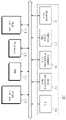
도 1은 본 발명의 실시 예에 따른 컴퓨팅 시스템을 보여주는 블록도이다. 도 1을 참조하면, 컴퓨팅 시스템(10)은 호스트(11) 및 저장 장치(100)를 포함한다. 예시적으로, 컴퓨팅 시스템(10)은 컴퓨터, 노트북, 서버, 워크 스테이션, 휴대용 통신 단말기, PDA(Personal Digital Assistant), PMP(Portable Media Player), 스마트폰, 또는 웨어러블(Wearable) 장치와 같은 컴퓨팅 시스템 또는 정보 처리 시스템일 수 있다. 호스트(11)는 커맨드(CMD)를 저장 장치(100)로 전송하여, 저장 장치(120)에 저장된 데이터(DATA)를 읽거나 또는 저장 장치(100)에 데이터를 저장할 수 있다.1 is a block diagram illustrating a computing system according to an embodiment of the present invention. Referring to FIG. 1 , a
저장 장치(100)는 메모리 컨트롤러(110) 및 불휘발성 메모리 장치(120)를 포함할 수 있다. 예시적으로, 저장 장치(100)는 SSD(solid state drive), 메모리 카드, 메모리 스틱 등과 같은 대용량 저장 매체일 수 있다.The
메모리 컨트롤러(110)는 호스트(11)로부터의 커맨드(CMD)에 응답하여 불휘발성 메모리 장치(120)를 제어할 수 있다. 불휘발성 메모리 장치(120)는 메모리 컨트롤러(110)의 제어에 따라 데이터를 저장하거나 또는 저장된 데이터를 메모리 컨트롤러(110)로 제공할 수 있다.The
본 발명의 실시 예에 따른 메모리 컨트롤러(110)는 리소스 풀(111), 커맨드 큐(112), 커맨드 처리부(113), 지연 연산부(114), 및 플래시 변환 계층(115)(FTL; Flash Translation Layer)을 포함할 수 있다. 이하에서, 본 발명의 실시 예들을 명확하게 설명하기 위하여, 호스트(11)로부터 수신된 커맨드(CMD)는 쓰기 커맨드인 것으로 가정한다. 그러나 본 발명의 범위가 이에 한정되는 것은 아니며, 메모리 컨트롤러(110)는 호스트(11)로부터 다양한 커맨드를 수신하고, 수신된 커맨드에 따라 동작할 수 있다.The
리소스 풀(111)은 호스트(11)로부터의 커맨드(CMD)를 처리하기 위한 다양한 자원들을 포함할 수 있다. 예를 들어, 리소스 풀(111)은 쓰기 버퍼, 읽기 버퍼 등을 포함하거나 또는 관리할 수 있다. 리소스 풀(111)의 쓰기 버퍼, 읽기 버퍼 등은 커맨드(CMD)를 처리하기 위하여 할당(또는 사용)될 수 있고, 커맨드(CMD)가 처리된 이후에, 가용한 형태로 해제(또는 반환)될 수 있다. 예시적으로, 리소스 풀(111)의 자원들은 FTL(115)의 유지 관리 동작(예를 들어, 가비지 콜렉션(garbage collection) 동작, 리드 리클레임 동작, 데이터 복구 동작, 데이터 백업 동작 등)에 의해 할당(또는 사용)되거나 해제(또는 반환)될 수 있다. 예시적으로, 리소스 풀(111)의 자원들은 저장 장치(100)의 초기화시 미리 설정되거나, 또는 저장 장치(100)의 동작 도중에 변경될 수 있다.The
커맨드 큐(112)는 호스트(11)로부터 수신된 커맨드(CMD)를 큐잉하도록 구성될 수 있다. 예를 들어, 커맨드 큐(112)는 호스트(11)로부터의 커맨드(CMD)를 수신된 순서 또는 우선 순위 순서에 따라 큐잉하도록 구성될 수 있다. 또는 커맨드 큐(112)는 미리 정해진 알고리즘에 따라 수신된 커맨드를 큐잉하도록 구성될 수 있다.The
커맨드 처리부(113)는 커맨드 큐(112)에 큐잉된 커맨드를 처리하도록 구성될 수 있다. 예를 들어, 커맨드 처리부(113)는 커맨드 큐(112)에 큐잉된 복수의 커맨드들 중 적어도 하나의 커맨드(CMD)를 페치하고, 페치된 커맨드(CMD)를 처리할 수 있다. 예시적으로, 커맨드 처리부(113)에 의해 커맨드(CMD)가 처리되는 것은 커맨드에 대한 쓰기 버퍼가 할당되고, 할당된 쓰기 버퍼에 호스트(11)로부터의 쓰기 데이터가 저장되는 것을 의미할 수 있다. 이하에서, 적절한 쓰기 버퍼 할당 동작 및 할당된 쓰기 버퍼에 쓰기 데이터를 저장하는 동작 등은 커맨드 처리부(113)에 의한 "커맨드 처리(command process)"라 칭한다. 즉, 커맨드 처리부(113)가 커맨드(CMD)를 처리하는 것은 커맨드(CMD)에 대한 쓰기 버퍼가 할당되는 것 및 할당된 쓰기 버퍼에 쓰기 데이터가 저장되는 것을 포함할 수 있다.The
상술된 바와 같이, 커맨드 처리부(113)는 리소스 풀(111)에 포함된 쓰기 버퍼 중 일부를 할당함으로써 페치된 커맨드를 처리할 수 있다. 이 때, 리소스 풀(111)의 가용한 쓰기 버퍼가 충분하지 않은 경우, 커맨드 처리부(113)는 페치된 커맨드를 처리할 수 없기 때문에, 가용한 쓰기 버퍼가 충분해진 이후에 페치된 커맨드를 처리할 것이다.As described above, the
예시적으로, 앞서 설명된 바와 같이, FTL(115)의 유지 관리 동작이 수행되는 경우, 유지 관리 동작에 의해 쓰기 버퍼가 할당(또는 사용)되기 때문에, 리소스 풀(111)의 가용한 쓰기 버퍼가 충분하지 않을 수 있다. 이 경우, 가용한 쓰기 버퍼가 확보된 이후에, 페치된 커맨드가 처리되기 때문에, 페치된 커맨드에 대한 지연 시간이 급격히 증가할 수 있다. 즉, 저장 장치(100)의 특정 조건(예를 들어, 가비지 콜렉션이 수행되는 조건)에서 커맨드에 대한 지연 시간이 급격하게 증가할 수 있다.Illustratively, as described above, when the maintenance operation of the
본 발명의 실시 예에 따른 커맨드 처리부(113)는 지연 연산부(114)에 의해 연산된 지연 시간을 기반으로 페치된 커맨드를 처리(또는 지연 처리(deferred-process))할 수 있다. 예를 들어, 지연 연산부(114)는 리소스 풀(111)의 현재 가용한 쓰기 버퍼의 크기, 이전에 가용한 쓰기 버퍼의 크기, 및 기준치를 기반으로 지연 시간을 연산할 수 있다. 즉, 지연 연산부(114)에 의해 연산된 지연 시간은 현재 가용한 쓰기 버퍼의 크기뿐만 아니라, 가용한 쓰기 버퍼의 변화량까지 반영된다. 따라서, 연산된 지연 시간을 기반으로 페치된 커맨드가 처리되는 경우, 가용한 쓰기 버퍼가 각 커맨드 처리시에 확보될 수 있기 때문에, 특정 조건에서의 커맨드(CMD)에 대한 급격한 지연 증가를 방지할 수 있다. 지연 연산부(114)의 지연 시간에 대한 연산 동작은 도 3 및 도 4를 참조하여 더욱 상세하게 설명된다.The
즉, 상술된 바와 같이, 커맨드 처리부(113)는 연산된 지연 시간을 기반으로 커맨드를 처리함으로써, 커맨드에 대한 지연 시간이 급격하게 증가하는 것을 방지할 수 있다.That is, as described above, the
FTL(115)은 커맨드 처리부(113)에 의해 처리된 커맨드(CMD)를 기반으로 불휘발성 메모리 장치(120)에 대한 동작을 수행할 수 있다. 예시적으로, FTL(115)은 불휘발성 메모리 장치(120)가 효율적으로 사용될 수 있도록, 호스트(11) 및 불휘발성 메모리 장치(120) 사이의 인터페이스를 제공할 수 있다. FTL(115)은 호스트(11)로부터 제공되는 논리적 어드레스를 불휘발성 메모리 장치(120)에서 사용 가능한 물리적 어드레스로 변환하는 동작을 수행할 수 있다. FTL(115)은 맵핑 테이블(미도시)을 통해 상술된 어드레스 변환 동작을 수행할 수 있다.The
예시적으로, FTL(115)은 앞서 설명된 바와 같이, 가비지 콜렉션 동작, 리드 리클레임 동작, 데이터 복구 동작, 데이터 백업 동작 등과 같은 유지 관리 동작을 수행할 수 있다. 이 때, FTL(115)은 유지 관리 동작을 수행하기 위하여, 리소스 풀(111)의 자원(예를 들어, 쓰기 버퍼)을 할당(또는 사용)하고, 유지 관리 동작이 완료된 이후에 할당(또는 사용)된 자원을 해제(또는 반환)할 수 있다.For example, as described above, the
상술된 바와 같이, 본 발명의 실시 예에 따른 저장 장치(100)는 리소스 풀(111)의 현재 상태 및 이전 상태에서 할당된 쓰기 버퍼의 크기 및 기준 크기를 기반으로 지연 시간을 연산하고, 연산된 지연 시간을 기반으로 커맨드를 지연-처리함으로써, 특정 조건에서 커맨드의 급격한 지연을 방지할 수 있다.As described above, the
도 2는 도 1의 메모리 컨트롤러(110)를 보여주는 블록도이다. 도 1 및 도 2를 참조하면, 메모리 컨트롤러(110)는 리소스 풀(111), 커맨드 큐(112), 커맨드 처리부(113), 지연 연산부(114), FTL(115), 프로세서(116), RAM(117), 호스트 인터페이스(118), 및 플래시 인터페이스(119)를 포함할 수 있다. 리소스 풀(111), 커맨드 큐(112), 커맨드 처리부(113), 지연 연산부(114), 및 FTL(115)은 도 1을 참조하여 설명되었으므로, 이에 대한 상세한 설명은 생략된다.FIG. 2 is a block diagram illustrating the
프로세서(116)는 메모리 컨트롤러(110)의 제반 동작을 제어할 수 있다. RAM(117)은 메모리 컨트롤러(110)가 동작하는데 요구되는 다양한 정보를 저장할 수 있다. 예시적으로, RAM(117)은 리소스 풀(111)에 포함된 쓰기 버퍼 또는 리소스 풀(111)에 의해 관리되는 쓰기 버퍼일 수 있다. 그러나, 본 발명의 범위가 이에 한정되는 것은 아니며, 리소스 풀(111)에 포함된 또는 리소스 풀(111)에 의해 관리되는 쓰기 버퍼는 별도의 버퍼 메모리일 수 있다.The
예시적으로, 리소스 풀(111), 커맨드 큐(112), 커맨드 처리부(113), 지연 연산부(114), FTL(115) 각각은 소프트웨어 구성, 하드웨어 구성, 또는 그것들의 조합의 형태로 구현될 수 있다. 리소스 풀(111), 커맨드 큐(112), 커맨드 처리부(113), 지연 연산부(114), FTL(115) 각각은 소프트웨어 구성으로 구현된 경우, 각 소프트웨어 구성들은 RAM(117)에 저장되고, RAM(117)에 저장된 각 소프트웨어 구성들은 프로세서(116)에 의해 구동될 수 있다.Illustratively, each of the
메모리 컨트롤러(110)는 호스트 인터페이스(118)를 통해 호스트(11)와 통신할 수 있다. 예시적으로, 호스트 인터페이스(118)는 DDR(Double Data Rate), USB (Universal Serial Bus), MMC (multimedia card), eMMC(embedded MMC), PCI (peripheral component interconnection), PCI-E (PCI-express), ATA (Advanced Technology Attachment), Serial-ATA, Parallel-ATA, SCSI (small computer small interface), ESDI (enhanced small disk interface), IDE (Integrated Drive Electronics), 파이어와이어(Firewire), UFS(Universal Flash Storage), NVMe (Nonvolatile Memory express) 등과 같은 인터페이스들 중 적어도 하나를 포함할 수 있다. 메모리 컨트롤러(110)는 플래시 인터페이스(119)를 통해 불휘발성 메모리 장치(120)와 통신하도록 구성될 수 있다.The
도 3은 도 1의 메모리 컨트롤러(110)의 동작 방법을 보여주는 순서도이다. 이하에서, 간결한 설명을 위하여, 메모리 컨트롤러(110)의 동작 방법을 기준으로 본 발명의 실시 예가 설명된다. 그러나, 본 발명의 범위가 이에 한정되는 것은 아니며, 각 단계의 동작은 메모리 컨트롤러(110)에 의해 또는 메모리 컨트롤러(110)에 포함된 구성 요소들 각각에 의해 또는 소프트웨어를 구동하는 메모리 컨트롤러(110)의 프로세서(116)에 의해 수행될 수 있다.3 is a flowchart illustrating an operation method of the
이하에서, 간결한 설명을 위하여, 현재 가용 버퍼(ABCR)(current available buffer), 이전 가용 버퍼(ABPR)(previous available buffer)의 용어들이 사용된다. 현재 가용 버퍼(ABCR)는 현재 상태 또는 현재 시점에서 사용 가능한 쓰기 버퍼(즉, 특정 동작을 위해 할당되지 않은 쓰기 버퍼 또는 특정 동작을 위해 할당될 수 있는 쓰기 버퍼)를 가리키고, 이전 가용 버퍼(ABPR)는 이전 상태에서 사용 가능한 쓰기 버퍼를 가리킨다.Hereinafter, for concise description, terms of a current available buffer (ABCR ) and a previously available buffer (ABPR ) are used. The currently available buffer (ABCR ) points to a write buffer available in the current state or at the current point in time (that is, a write buffer that is not allocated for a specific operation or a write buffer that can be allocated for a specific operation), and the previous available buffer (ABPR ) points to an available write buffer in the previous state.
또한, 설명의 편의를 위하여, 현재 가용 버퍼(ABCR)의 크기는 현재 가용 버퍼(ABCR)라 지칭될 수 있고, 이전 가용 버퍼(ABPR)의 크기는 이전 가용 버퍼(ABPR)라 지칭될 수 있다. 즉, 현재 가용 버퍼(ABCR)가 "특정 값"이라 지칭되는 것은 현재 가용 버퍼(ABCR)의 크기가 "특정 값"임을 의미한다. 그러나 상술된 수치들 및 가정들은 본 발명의 기술적 사상을 명확하고 간결하게 설명하기 위한 것이며, 본 발명의 범위가 이에 한정되는 것은 아니다.In addition, for convenience of description, the size of the currently available buffer (ABCR ) may be referred to as a currently available buffer (ABCR ), and the size of the previously available buffer (ABPR ) is referred to as a previously available buffer (ABPR ). can be That is, when the currently available buffer ABCR is referred to as a “specific value”, it means that the size of the currently available buffer ABCR is a “specific value”. However, the above-mentioned numerical values and assumptions are for clearly and concisely explaining the technical idea of the present invention, and the scope of the present invention is not limited thereto.
도 1 및 도 3을 참조하면, S110 단계에서, 메모리 컨트롤러(110)는 커맨드 큐(112)로부터 커맨드(CMD)를 페치할 수 있다. 예를 들어, 커맨드 큐(112)는 호스트(11)로부터의 복수의 커맨드들을 큐잉하도록 구성될 수 있다. 커맨드 처리부(113)는 커맨드 큐(112)에 큐잉된 복수의 커맨드들 중 적어도 하나의 커맨드(CMD)를 페치할 수 있다. 예시적으로, 커맨드 큐(112)는 생략될 수 있으며, 이 경우, 커맨드를 페치하는 동작은 호스트(11)로부터 커맨드를 수신하는 동작으로 대체될 수 있다.1 and 3 , in operation S110 , the
S120 단계에서, 메모리 컨트롤러(110)는 현재 가용 버퍼(ABCR)가 기준치(TH)보다 작은지 판별할 수 있다. 예를 들어, 메모리 컨트롤러(110)의 지연 연산부(114)는 리소스 풀(111)을 감시(monitoring)함으로써, 현재 가용 버퍼(ABCR)를 감지할 수 있다. 리소스 풀(111)은 현재 가용 버퍼(ABCR)가 기준치(TH)보다 작은지 판별할 수 있다. 예시적으로, 기준치(TH)는 저장 장치(100)의 성능 유지를 위하여 미리 설정된 값일 수 있다. 저장 장치(100)의 성능 유지를 위하여, 리소스 풀(111)의 가용한 쓰기 버퍼의 크기는 기준치(TH) 이상으로 유지되도록 구성될 수 있다.In operation S120 , the
현재 가용 버퍼(ABCR)가 기준치(TH)보다 작지 않은 경우, S130 단계에서, 메모리 컨트롤러(110)는 페치된 커맨드(CMD)를 정상-처리(normal process)할 수 있다. 예를 들어, 현재 가용 버퍼(ABCR)의 크기가 기준치(TH)보다 작지 않은 것은 리소스 풀(111)에 가용한 쓰기 버퍼가 충분하다는 것을 의미할 수 있다. 따라서 메모리 컨트롤러(110)는 지연 시간 없이 또는 미리 정해진 지연 시간을 기반으로 페치된 커맨드(CMD)에 대한 쓰기 버퍼를 할당함으로써, 페치된 커맨드(CMD)를 정상-처리할 수 있다. 예시적으로, 미리 정해진 지연 시간은 호스트(11) 및 저장 장치(100) 사이의 인터페이스에 의해 미리 정의된 시간이거나 또는 저장 장치(100)의 성능 유지를 위하여 미리 정의된 시간일 수 있다.When the currently available buffer ABCR is not smaller than the reference value TH, in operation S130 , the
현재 가용 버퍼(ABCR)의 크기가 기준치(TH)보다 작은 경우, S140 단계에서, 메모리 컨트롤러(110)는 현재 가용 버퍼(ABCR)(current available buffer), 이전 가용 버퍼(ABPR)(previous available buffer), 및 기준치(TH)를 기반으로 지연 시간(DL)을 연산할 수 있다. 예시적으로, 지연 시간(DL)은 현재 가용한 버퍼의 크기뿐만 아니라, 가용한 쓰기 버퍼의 변화량에 대한 정보를 반영할 수 있다. 지연 시간(DL)의 연산 방법은 도 4를 참조하여 더욱 상세하게 설명된다.When the size of the currently available buffer ABCR is smaller than the reference value TH, in step S140 , the
S150 단계에서, 메모리 컨트롤러(110)는 연산된 지연 시간(DL)을 기반으로 커맨드(CMD)를 지연-처리(deferred process)할 수 있다. 예를 들어, 메모리 컨트롤러(110)는 커맨드 큐(112)로부터 커맨드(CMD)를 페치한 시점으로부터 지연 시간(DL)이 경과한 이후에, 커맨드(CMD)를 처리할 수 있다. 이와 같이, 커맨드(CMD)를 연산된 지연 시간(DL)만큼 지연-처리함으로써, 지연 시간(DL) 동안 리소스 풀(111)에 가용한 쓰기 버퍼가 확보될 수 있다. 따라서, 이후의 커맨드 처리시, 충분한 쓰기 버퍼가 확보되기 때문에, 특정 조건(예를 들어, 가비지 콜렉션 상황)에서 커맨드의 급격한 지연이 방지될 수 있다.In operation S150 , the
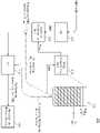
도 4는 도 3의 동작 방법을 상세하게 설명하기 위한 도면이다. 본 발명의 기술적 사상을 용이하게 설명하기 위하여, 리소스 풀(111)은 쓰기 버퍼로 구성되고, 쓰기 버퍼의 전체 크기는 "100"인 것으로 가정한다. 또한, 기준치(TH)는 "40"이고, 현재 가용 버퍼(ABCR)는 "20"이고, 이전 가용 버퍼(ABPR)는 "40"인 것으로 가정한다. 즉, 도 4를 참조하여, 현재 가용 버퍼(ABCR)가 기준치(TH)보다 작은 경우의 동작이 설명된다. 도 4에서, 현재 할당된 쓰기 버퍼(즉, 현재 사용중인 쓰기 버퍼)는 음영으로 표시된다.FIG. 4 is a view for explaining the operation method of FIG. 3 in detail. In order to easily explain the technical idea of the present invention, it is assumed that the
도 1, 도 3, 및 도 4를 참조하면, 호스트(11)로부터의 복수의 커맨드들(CMD1~CMDn)이 커맨드 큐(112)에 큐잉될 수 있다. 커맨드 처리부(113)는 커맨드 큐(112)에 큐잉된 복수의 커맨드들(CMD1~CMDn) 중 제1 커맨드(CMD1)를 페치할 수 있다. 예시적으로, 제1 커맨드(CMD1)는 커맨드 큐(112)의 큐잉 방식에 따라 가장 먼저 처리되어야 할 커맨드일 수 있다.1, 3, and 4 , a plurality of commands CMD1 to CMDn from the
이 때, 지연 연산부(114)는 리소스 풀(111)에서 현재 가용 버퍼(ABCR)의 크기가 기준치(TH)보다 작은지 판별할 수 있다. 앞서 설명된 바와 같이, 현재 가용 버퍼(ABCR)가 기준치(TH)보다 작으므로, 지연 연산부(114)는 지연 시간(DL)을 연산할 수 있다. 예시적으로, 지연 연산부(114)는 수학식 1을 기반으로 지연 시간(DL)을 연산할 수 있다.In this case, the

수학식 1을 참조하면, "DL"은 연산된 지연 시간을 가리키고, "ABCR"은 현재 상태의 현재 가용 버퍼의 크기를 가리키고, "TH"는 가용한 쓰기 버퍼에 대한 기준치를 가리키고, "P"는 현재 가용 버퍼의 크기 및 기준치의 크기 차이를 지연 시간으로 변환하기 위한 제1 제어 변수를 가리키고, "ABPR"은 이전 상태의 이전 가용 버퍼의 크기를 가리키고, "D"는 가용 버퍼의 변화량을 지연 시간으로 변환하기 위한 제2 제어 변수를 가리킨다.Referring to
앞서 설명된 바와 같이, 현재 가용 버퍼(ABCR)는 제1 커맨드(CMD1)가 페치되는 시점에서 가용한 쓰기 버퍼의 크기를 가리키고, 이전 가용 버퍼(ABCR)의 크기는 제1 커맨드(CMD1) 이전에 다른 커맨드가 페치된 시점(즉, 제1 커맨드(CMD1) 직전에 다른 커맨드가 페치된 시점)에서 가용한 쓰기 버퍼의 크기를 가리킬 수 있다.As described above, the current available buffer ABCR indicates the size of the write buffer available at the time the first command CMD1 is fetched, and the size of the previous available buffer ABCR is the first command CMD1 . It may indicate the size of the write buffer available at a point in time when another command was previously fetched (ie, when another command was fetched immediately before the first command CMD1).
수학식 1의 우항의 제1 항(즉, "[TH-ABCR]*P")을 참조하면, 기준치(TH)는 미리 정해진 값이므로, 현재 가용 버퍼(ABCR)가 증가할수록 지연 시간(DL)은 감소하고, 현재 가용 버퍼(ABCR)가 감소할수록 지연 시간(DL)은 증가할 것이다. 수학식 1의 우항의 제2 항(즉, "[(TH-ABCR)-(TH-ABPR)]*D")을 참조하면, 이전 가용 버퍼(ABPR) 및 현재 가용 버퍼(ABCR) 사이의 차이가 증가할수록 지연 시간(DL)이 증가할 것이다. 다시 말해서, 현재 가용 버퍼(ABCR)가 이전 가용 버퍼(ABPR)보다 큰 경우 지연 시간(DL)은 감소하고, 현재 가용 버퍼(ABCR)가 이전 가용 버퍼(ABPR)보다 작은 경우 지연 시간(DL)은 증가할 것이다. 즉, 본 발명에 따른 지연 연산부(114)는 리소스 풀(111)의 현재 가용 버퍼(ABCR)뿐만 아니라, 가용한 버퍼의 변화량(예를 들어, (TH-ABCR)-(TH-ABPR))을 반영하여 지연 시간(DL)을 연산할 수 있다.Referring to the first term (ie, "[TH-ABCR ]*P") of the right-hand side of
커맨드 처리부(113)는 지연 시간(DL)을 기반으로 제1 커맨드(CMD1)를 처리할 수 있다. 예를 들어, 커맨드 처리부(113)는 연산된 지연 시간(DL)이 경과한 이후에, 제1 커맨드(CMD1)를 지연-처리할 수 있다. 예시적으로, 커맨드 처리부(113)에 의해 제1 커맨드(CMD1)가 처리되는 것은 도 4의 쇄선(dash line)으로 도시된 바와 같이, 리소스 풀(111)로부터 쓰기 버퍼가 할당되는 것을 포함할 수 있다. 다시 말해서, 커맨드 처리부(113)는 지연 시간(DL)이 경과한 이후에, 제1 커맨드(CMD1)를 위한 쓰기 버퍼를 할당함으로써, 제1 커맨드(CMD1)를 지연-처리할 수 있다.The
이후에, FTL(115)은 처리된 제1 커맨드(CMD1)에 대응하는 동작을 수행할 수 있다. 예를 들어, 제1 커맨드(CMD1)가 쓰기 커맨드인 경우, FTL(115)은 할당된 쓰기 버퍼에 저장된 쓰기 데이터를 불휘발성 메모리 장치(120)에 저장할 수 있다.Thereafter, the
예시적으로, 메모리 컨트롤러(110)는 페치된 제1 커맨드(CMD1)가 처리된 이후에, 단, 처리된 제1 커맨드(CMD1)에 대한 동작이 FTL(115)에 의해 수행되기 이전에, 호스트(11)로 제1 커맨드(CMD1)에 대한 응답(response)을 제공할 수 있다. 제1 커맨드(CMD1)에 대한 응답(response)이 제공되는 시점은 제1 커맨드(CMD1)에 대한 지연 또는 레이턴시(latency)로 작용할 수 있다.For example, after the fetched first command CMD1 is processed, the
예시적으로, 상술된 실시 예에서, 현재 가용 버퍼(ABCR), 이전 가용 버퍼(ABPR), 및 기준치(TH)는 "특정한 값"인 것으로 설명되었으나, 본 발명의 범위가 이에 한정되는 것은 아니다. 예를 들어, 현재 가용 버퍼(ABCR), 이전 가용 버퍼(ABPR), 및 기준치(TH)는 리소스 풀(111) 전체에 대한 비율로서 연산될 수 있다.Illustratively, in the above-described embodiment, it has been described that the current available buffer (ABCR ), the previously available buffer (ABPR ), and the reference value (TH) are “specific values”, but the scope of the present invention is limited thereto. not. For example, the current available buffer ABCR, the previous available buffer ABPR, and the reference value TH may be calculated as a ratio of the
상술된 바와 같이, 현재 가용 버퍼(ABCR)가 기준치(TH)보다 작은 경우, 메모리 컨트롤러(110)는 현재 가용 버퍼(ABCR), 이전 가용 버퍼(ABPR), 및 기준치(TH)를 기반으로 페치된 제1 커맨드(CMD1)에 대한 지연 시간(DL)을 연산하고, 연산된 지연 시간(DL)을 기반으로 페치된 제1 커맨드(CMD1)를 처리할 수 있다. 이 경우, 지연 시간(DL) 동안 리소스 풀(111)에서 가용한 쓰기 버퍼가 확보될 수 있기 때문에, 이후의 특정 커맨드들에 대한 급격한 지연 증가가 방지될 수 있다.As described above, when the currently available buffer ABCR is less than the reference value TH, the
도 5는 도 4의 메모리 컨트롤러(110)의 동작 방법을 설명하기 위한 타이밍도이다. 도면의 간결성 및 설명의 편의를 위하여, 제1 및 제2 커맨드들(CMD1, CMD2)에 대한 처리가 도 5에 도시된다. 또한, 앞서 설명된 바와 유사하게, 기준치(TH)는 "40"인 것으로 가정한다. 또한, 메모리 컨트롤러(110)의 동작을 기준으로 도 5의 타이밍도가 설명되나, 본 발명의 기술적 사상이 이에 한정되는 것은 아니며, 도 5의 타이밍도에 따른 동작들 각각은 메모리 컨트롤러(110)에 포함된 구성요소들 각각에 의해 또는 소프트웨어를 구동하는 프로세서(116)(도 2 참조)에 의해 수행될 수 있다.FIG. 5 is a timing diagram for explaining an operation method of the
도 4 및 도 5를 참조하면, 제1 시점(t1)에서, 메모리 컨트롤러(110)는 제1 커맨드(CMD1)를 페치할 수 있다. 예시적으로, 제1 커맨드(CMD1)는 커맨드 큐(112)에 큐잉된 복수의 커맨드들(CMD1~CMDn) 중 하나일 수 있다.4 and 5 , at a first time point t1 , the
제1 시점(t1) 이전의 제0 시점(t0)에서, 제0 가용 버퍼(AB0)는 "40"일 수 있다. 예시적으로, 제0 시점(t0)은 제1 커맨드(CMD1) 이전에(또는 직전에) 커맨드 큐(112)로부터 커맨드가 페치된 시점일 수 있다. 제1 시점(t1)에서 제1 가용 버퍼는 "20"일 수 있다.At a 0 th time t0 before the first time t1, the 0 th available buffer AB0 may be “40”. For example, the zeroth time point t0 may be a time point at which a command is fetched from the
제1 시점(t1)을 기준으로, 제0 가용 버퍼(AB0)는 이전 가용 버퍼(즉, ABPR)이고, 제1 가용 버퍼(AB1)는 현재 가용 버퍼(즉, ABCR)일 수 있다. 이 경우, 이전 가용 버퍼보다 현재 가용 버퍼가 작다. 다시 말해서, 제0 시점(t0)보다 제1 시점(t1)에서 더 많은 쓰기 버퍼가 사용되는 상태일 것이다. 이러한 현상은 FTL(115)의 유지 관리 동작에 의해 발생될 수 있다. 예를 들어, FTL(115)이 유지 관리 동작(예를 들어, 가비지 콜렉션)을 수행하는 경우, FTL(115)는 리소스 풀(111)로부터 쓰기 버퍼를 할당(또는 사용)할 수 있다. 즉, FTL(115)의 유지 관리 동작에 의해 할당된 쓰기 버퍼(또는 사용된 쓰기 버퍼)의 크기가 증가할 수 있다.Based on the first time point t1 , the zeroth available buffer AB0 may be a previously available buffer (ie, ABPR ), and the first available buffer AB1 may be a currently available buffer (ie, ABCR ). In this case, the currently available buffer is smaller than the previous available buffer. In other words, more write buffers will be used at the first time point t1 than at the zeroth time point t0. This phenomenon may be caused by a maintenance operation of the
앞서 설명된 바와 같이, 제1 가용 버퍼(AB1)가 기준치(TH)보다 작기 때문에, 메모리 컨트롤러(110)는 제0 및 제1 가용 버퍼들(AB0, AB1) 및 기준치(TH)를 기반으로 지연 시간(DL)을 연산할 수 있다. 예를 들어, 앞서 설명된 수학식 1을 참조하면, 제1 시점(t1)을 기준으로, 현재 가용 버퍼(ABCR)는 제1 가용 버퍼(AB1)이고, 이전 가용 버퍼(ABPR)는 제0 가용 버퍼(AB0)이므로, 현재 가용 버퍼(ABCR) 및 이전 가용 버퍼(ABPR)는 각각 "20" 및 "40"일 것이다. 설명의 편의를 위하여, 제1 및 제2 제어 변수들(P, D)은 "1"인 것으로 가정하면(그러나, 본 발명의 범위가 이에 한정되는 것은 아니다.), 제1 시점(t1)에서 연산된 제1 지연 시간(DL1)은 "40"의 값과 대응될 것이다.As described above, since the first available buffer AB1 is smaller than the reference value TH, the
메모리 컨트롤러(110)는 "40"의 값과 대응하는 제1 지연 시간(DL1)을 기반으로 제1 커맨드(CMD1)를 지연 처리할 수 있다. 예를 들어, 메모리 컨트롤러(110)는 제1 시점(t1)으로부터 제1 시간(T1)이 경과한 제2 시점(t2)에서, 제1 커맨드(CMD1)를 처리할 수 있다. 이 때, 제1 시간(T1)은 제1 지연 시간(DL1)보다 길거나 같을 수 있다. 즉, 메모리 컨트롤러(110)는 제1 지연 시간(DL1)이 경과한 이후에, 제1 커맨드(CMD1)를 처리할 수 있다. 다시 말하면, 메모리 컨트롤러(110)는 적어도 제1 지연 시간(DL1)만큼 제1 커맨드(CMD1)의 처리를 지연시킬 수 있다.The
이후에, 메모리 컨트롤러(110)는 제3 시점(t3)에서 제2 커맨드(CMD2)를 페치하고, 제2 지연 시간(DL2)을 연산할 수 있다. 제3 시점(t3)에서 제2 가용 버퍼(AB2)는 "20"일 수 있다. 제3 시점(t3)을 기준으로, 현재 가용 버퍼(ABCR)는 제2 가용 버퍼(AB2)이고, 이전 가용 버퍼(ABPR)는 제1 가용 버퍼(AB1)일 수 있다. 앞서 설명된 바와 유사하게, 제어값들(P, D)이 "1"인 것으로 가정하면, 제2 커맨드(CMD2)에 대한 제2 지연 시간(DL2)은 "20"의 값과 대응될 것이다.Thereafter, the
메모리 컨트롤러(110)는 "20"의 값과 대응하는 제2 지연 시간(DL2)을 기반으로 제2 커맨드(CMD2)를 지연-처리할 수 있다. 예를 들어, 메모리 컨트롤러(110)는 제3 시점(t3)으로부터 제2 시간(T2)이 경과한 제4 시점(t4)에서, 제2 커맨드(CMD2)를 처리할 수 있다. 이 때, 제2 시간(T2)은 제2 지연 시간(DL2)보다 길거나 같고, 제1 지연 시간(DL1)보다 짧을 수 있다. 다시 말해서, 메모리 컨트롤러(110)는 적어도 제2 지연 시간(DL2)만큼 제2 커맨드(CMD2)의 처리를 지연시킬 수 있다.The
제1 및 제2 지연 시간들(DL1, DL2)이 서로 다른 이유는 제1 및 제3 시점들(t1, t3) 각각에서 현재 가용 버퍼(ABCR)는 서로 동일하나, 가용 버퍼의 변화량이 다르기 때문이다. 예를 들어, 제1 시점(t1)을 기준으로, 현재 가용 버퍼(AB1) 및 이전 가용 버퍼(AB0)의 차이는 "20"이다. 반면에, 제2 시점(t2)을 기준으로, 현재 가용 버퍼(AB2) 및 이전 가용 버퍼(AB1)의 차이는 "0"이다. 이는 제1 시점(t1)에서 가용한 버퍼가 감소함(또는 버퍼의 사용량이 증가) 을 의미하고, 제3 시점(t3)에서 가용한 버퍼의 감소가 없음을 의미한다. 예시적으로, 가용 버퍼가 감소하는 것은 FTL(115)의 유지 관리 동작에 의해 리소스 풀(111)의 쓰기 버퍼가 할당(또는 사용)됨을 의미할 수 있다.The reason that the first and second delay times DL1 and DL2 are different from each other is that at each of the first and third time points t1 and t3 , the current available buffers ABCR are the same, but the amount of change in the available buffers is different. Because. For example, based on the first time point t1 , the difference between the current available buffer AB1 and the previous available buffer AB0 is “20”. On the other hand, based on the second time point t2, the difference between the current available buffer AB2 and the previous available buffer AB1 is “0”. This means that the buffer available at the first time point t1 is decreased (or the amount of the buffer used is increased), and there is no decrease in the available buffers at the third time point t3 . For example, the decrease in the available buffer may mean that the write buffer of the
다시 말해서, 제1 시점(t1)에서는 가용 버퍼의 크기가 감소하는 추세이므로, 제1 커맨드(CMD1)에 대한 지연 시간을 증가시킴으로써, 가용 버퍼를 확보할 수 있고, 제2 시점(t2)에서는 가용 버퍼의 크기가 감소하지 않기 때문에, 제1 시점(t1)에서의 지연 시간보다 지연 시간을 짧게 하더라도, 가용 버퍼가 확보될 수 있음을 의미한다.In other words, since the size of the available buffer tends to decrease at the first time point t1, an available buffer can be secured by increasing the delay time for the first command CMD1, and the available buffer can be secured at the second time point t2. Since the size of the buffer does not decrease, it means that an available buffer can be secured even if the delay time is shorter than the delay time at the first time point t1 .
상술된 바와 같이, 본 발명에 따른 메모리 컨트롤러(110)는 리소스 풀(111)의 현재 가용 버퍼의 크기뿐만 아니라, 가용 버퍼의 변화량을 반영하여 커맨드에 대한 지연 시간을 연산함으로써, 특정 조건에서 커맨드의 급격한 지연을 방지할 수 있다.As described above, the
비록 도면에 도시되지는 않았으나, 예시적으로, 연산된 지연 시간(DL)이 특정 값보다 작은 경우, 메모리 컨트롤러(110)는 페치된 커맨드를 정상-처리할 수 있다. 예를 들어, 연산된 지연 시간(DL)이 음수(-) 값을 가질 수 있다. 이 경우, 메모리 컨트롤러(110)는 커맨드 처리를 위해 필요한 쓰기 버퍼가 충분하다면, 지연 시간 없이 또는 미리 정해진 지연 시간을 기반으로 커맨드를 처리할 수 있다.Although not shown in the drawings, for example, when the calculated delay time DL is less than a specific value, the
좀 더 상세한 예로서, 현재 가용 버퍼(ABCR)가 "30"이고, 이전 할당 버퍼(ABPR)가 "10"인 것으로 가정하면, (이 때, 제1 및 제2 제어 변수들(P, D)은 "1"인 것으로 가정함.) 수학식 1에 따라 지연 시간(DL)은 "-10"의 값(즉, 음수(-))과 대응될 것이다. 이는 가용 버퍼의 변화량이 증가하는 추세임을 의미한다. 다시 말해서, 버퍼의 할당 속도보다 버퍼의 해제 속도가 빠르기 때문에, 이후에 가용한 쓰기 버퍼가 빠르게 확보될 수 있음을 의미한다. 따라서, 지연 시간(DL)이 음수(-) 값과 대응되는 경우, 메모리 컨트롤러(110)가 지연 시간 없이 또는 미리 정해진 지연 시간을 기반으로 커맨드를 처리하더라도, 이후의 커맨드 처리시 충분한 쓰기 버퍼가 확보될 것이다.As a more detailed example, it is assumed that the current available buffer (ABCR ) is “30” and the previous allocation buffer ABPR is “10” (in this case, the first and second control variables P, D) is assumed to be “1”.) According to
예시적으로, 앞선 실시 예들에서, 이전 가용 버퍼(ABPR)는 어느 한 시점에 대한 가용 버퍼의 크기인 것으로 설명되었으나, 본 발명의 범위가 이에 한정되는 것은 아니다. 예를 들어, 이전 가용 버퍼(ABPR)는 특정 범위 내에 포함된 가용 버퍼의 평균치일 수 있다. 예를 들어, 이전 가용 버퍼는 특정 시점(예를 들어, 이전 시점)으로부터 현재 시점까지 감지된 가용 버퍼의 평균치일 수 있다.Illustratively, in the above embodiments, it has been described that the previous available buffer ABPR is the size of the available buffer for any one time point, but the scope of the present invention is not limited thereto. For example, the previous available buffer ABPR may be an average value of available buffers included within a specific range. For example, the previously available buffer may be an average of the detected available buffers from a specific time point (eg, a previous time point) to the current time point.
예시적으로, 앞선 실시 예들에서, 지연 연산부(114)는 현재 가용 버퍼(ABCR), 이전 가용 버퍼(ABPR), 및 기준치(TH)를 기반으로 지연 시간(DL)을 연산하였으나, 본 발명의 범위가 이에 한정되는 것은 아니다. 예를 들어, 지연 연산부(114)는 현재 할당된(또는 사용된) 버퍼의 크기, 이전에 할당된(또는 사용된) 버퍼의 크기, 및 기준치(이 때, 기준치는 할당된(또는 사용된) 버퍼에 대한 기준치임.)를 기반으로 지연 시간(DL)을 연산할 수 있다. 이 경우, 지연 시간은 수학식 2와 같이 연산될 수 있다.Illustratively, in the preceding embodiments, the

수학식 2를 참조하면, UBCR은 현재 할당된 쓰기 버퍼(또는 현재 사용 중인 쓰기 버퍼)의 크기를 가리키고, UBPR은 이전에 할당된 쓰기 버퍼(또는 이전에 사용 중이었던 쓰기 버퍼)의 크기를 가리키고, TH'은 할당된(또는 사용된) 쓰기 버퍼에 대한 기준치를 가리킨다. 나머지 변수들은 수학식 1을 참조하여 설명되었으므로, 이에 대한 상세한 설명은 생략된다. 수학식 2에 기재된 바와 같이, 지연 연산부(111)는 할당된 쓰기 버퍼의 크기 및 쓰기 버퍼의 할당량의 변화량을 기반으로 지연 시간(DL)을 연산할 수 있다.Referring to Equation 2, UBCR indicates the size of the currently allocated write buffer (or the currently used write buffer), and UBPR indicates the size of the previously allocated write buffer (or the previously used write buffer). , and TH' indicates the reference value for the allocated (or used) write buffer. Since the remaining variables have been described with reference to
예시적으로, 비록 도면에 도시되지는 않았으나, 지연 시간(DL)은 기준치(TH)로부터의 현재 가용 버퍼(ABCR)가 감산된 값을 누적한 값을 반영할 수 있다. 예를 들어, 수학식 1의 제1 항의 값([TH-ABCR], 즉, 기준치(TH) 및 현재 가용 버퍼(ABCR)의 차이 값)이 누적될 수 있다. 누적된 값은 지연 시간(DL)에 반영될 수 있다. 예를 들어, 지연 시간(DL)은 수학식 3과 같이 연산될 수 있다.For example, although not shown in the drawing, the delay time DL may reflect a value obtained by accumulating a value obtained by subtracting the current available buffer ABCR from the reference value TH. For example, the value of the first term of Equation 1 ([TH-ABCR ], that is, the difference value between the reference value TH and the currently available buffer ABCR ) may be accumulated. The accumulated value may be reflected in the delay time DL. For example, the delay time DL may be calculated as in Equation (3).

수학식 3을 참조하면, AB는 이전 시점들에서 검출된 가용 버퍼의 크기를 가리키고, I는 누적된 값을 지연 시간으로 변환하기 위한 제어 변수를 가리킨다. 나머지 변수들은 수학식 1을 참조하여 설명되었으므로, 이에 대한 상세한 설명은 생략된다. 즉, 수학식 3의 제3 항은 기준치(TH) 및 현재 가용 버퍼(ABCR)의 차이의 누적된 값을 가리킨다.Referring to Equation 3, AB indicates the size of an available buffer detected at previous time points, and I indicates a control variable for converting an accumulated value into a delay time. Since the remaining variables have been described with reference to
특정 상황(예를 들어, 현재 가용 버퍼가 "0"이고, 이전 가용 버퍼가 "0"인 상황 또는 현재 가용 버퍼(ABCR) 및 이전 가용 버퍼(ABPR)가 동일한 상황 등)에서, 수학식 3의 제2 항([(TH-ABCR)-(TH-ABPR)]*D)의 값이 "0"이 되고, 이 경우, 가용한 쓰기 버퍼의 변화량이 지연 시간(DL)에 반영되지 않을 수 있다. 이 경우, 수학식 3의 제3 항에 게시된 바와 같이, 기준치(TH) 및 현재 가용 버퍼(ABCR)의 차이의 누적된 값이 지연 시간(DL)에 반영될 수 있다. 따라서, 지연 시간(DL)을 기반으로 커맨드를 처리함으로써, 가용한 쓰기 버퍼를 충분히 확보할 수 있고, 이에 따라, 커맨드의 급격한 지연 증가가 방지될 수 있다. 상술된 지연 시간(DL)을 연산하기 위한 연산 방법들은 본 발명의 기술적 사상으로부터 벗어남 없이 다양하게 변형될 수 있다.In certain circumstances (for example, the current available buffer is "0" and the previous available buffer is "0", or the current available buffer (ABCR ) and the previous available buffer (ABPR ) are the same, etc.), the equation The value of the second term of 3 ([(TH-ABCR )-(TH-ABPR )]*D) becomes “0”, and in this case, the amount of change in the available write buffer is reflected in the delay time (DL) it may not be In this case, as posted in the third term of Equation 3, the accumulated value of the difference between the reference value TH and the currently available buffer ABCR may be reflected in the delay time DL. Accordingly, by processing the command based on the delay time DL, it is possible to sufficiently secure an available write buffer, and accordingly, a sudden increase in the delay of the command can be prevented. The above-described calculation methods for calculating the delay time DL may be variously modified without departing from the spirit of the present invention.
도 6은 도 4의 지연 연산부(114)를 예시적으로 보여주는 블록도이다. 도 4 및 도 6을 참조하면, 지연 연산부(114)는 레지스터(114A), 제1 감산기(114B), 제2 감산기(114C), 변수 제어기(114D), 및 가산기(114E)를 포함할 수 있다.6 is a block diagram exemplarily illustrating the
레지스터(114A)는 현재 가용 버퍼(AB[i])를 수신할 수 있다. 레지스터(114A)는 수신된 현재 가용 버퍼(AB[i])에 대한 정보 및 이전 가용 버퍼(AB[i-1])에 대한 정보를 저장할 수 있다. 예시적으로, 이전 가용 버퍼(AB[i-1])는 특정 시점에서의 가용 버퍼이거나 또는 특정 구간에서 가용 버퍼들의 평균치일 수 있다.
제1 감산기(114B)는 현재 가용 버퍼(AB[i])와 기준치(TH)의 차이를 연산하여 출력하도록 구성된다. 예를 들어, 제1 감산기(114B)는 기준치(TH)로부터 현재 가용 버퍼(AB[i])가 감산된 값을 출력할 수 있다. 예시적으로, 제1 감산기(114B)로부터 출력된 값은 수학식 1의 우항의 제1 항에 대응하는 값일 수 있다.The
제2 감산기(114C)는 레지스터(114A)로부터 이전 가용 버퍼(AB[i-1])를 수신하고, 현재 가용 버퍼(AB[i]) 및 이전 가용 버퍼(AB[i-1])의 차이를 연산하여 출력하도록 구성된다. 예를 들어, 제2 감산기(114C)는 이전 가용 버퍼(AB[i-1])로부터 현재 가용 버퍼(AB[i])가 감산된 값을 출력할 수 있다. 예시적으로, 제2 감산기(114C)로부터 출력된 값은 수학식 1의 우항의 제2 항과 대응하는 값일 수 있다.The
변수 제어기(114D)는 제1 및 제2 제어 변수들(P, D)을 제어하도록 구성된다. 수학식 1을 참조하여 설명된 바와 같이, 제1 및 제2 제어 변수들(P, D) 각각은 현재 가용 버퍼의 크기 및 기준치의 크기 차이를 지연 시간으로 변환하기 위한 제어 변수 및 가용 버퍼의 변화량을 지연 시간으로 변환하기 위한 제어 변수를 가리킨다. 변수 제어기(114D)는 제1 및 제2 제어 변수들(P, D)을 제어할 수 있다.The
예시적으로, 제2 제어 변수(D)는 현재 가용 버퍼(AB[i]) 및 이전 가용 버퍼(AB[i-1]) 각각을 감지한 시점에 따라 다르게 설정될 수 있다. 예를 들어, 현재 가용 버퍼(AB[i])를 감지한 시점 및 이전 가용 버퍼(AB[i-1]) 각각을 감지한 시점의 시간 차이가 클수록 제어 값(D)이 감소할 수 있다.Exemplarily, the second control variable D may be set differently depending on the time at which each of the currently available buffer AB[i] and the previously available buffer AB[i-1] is sensed. For example, the control value D may decrease as the time difference between the time at which the current available buffer AB[i] is sensed and the time at which each of the previous available buffers AB[i-1] is sensed increases.
변수 제어기(114D)로부터의 제1 및 제2 제어 변수들(P, D)은 각각 제1 및 제2 감산기들(114B, 114C)로부터의 출력 값들과 연산되어 가산기(114E)로 제공된다. 가산기(114E)는 입력된 값들을 합산하여 지연 시간(DL)을 출력할 수 있다.The first and second control variables P and D from the
예시적으로, 도 6에 도시된 지연 연산부(114)는 지연 시간(DL)을 연산하는 구성을 설명하기 위한 예시적인 것이며, 본 발명의 범위가 이에 한정되는 것은 아니다.Illustratively, the
지연 연산부(114)에 포함된 구성 요소들 각각은 하드웨어 형태로 구현될 수 있다. 또는 지연 연산부(114)에 포함된 구성 요소들 각각은 소프트웨어 형태로 구현될 수 있으며, 메모리 컨트롤러(110)의 프로세서(116)(도 2 참조) 또는 별도의 장치에 의해 구동될 수 있다.Each of the components included in the
도 7 및 도 8은 본 발명의 실시 예에 따른 메모리 컨트롤러(210)의 동작을 설명하기 위한 블록도 및 순서도이다. 본 발명의 실시 예를 명확하게 설명하기 위하여, 불필요한 구성 요소들은 도 7에서 생략된다. 또한, 도 1 내지 도 6을 참조하여 설명된 구성 요소들은 도 7 및 도 8에서 유사한 참조번호들로 표시되며, 앞서 설명된 구성들에 대한 상세한 설명은 생략된다.7 and 8 are block diagrams and flowcharts for explaining the operation of the
도 7 및 도 8을 참조하면, 메모리 컨트롤러(210)는 S210 단계 내지 S230 단계의 동작들을 수행할 수 있다. S210 단계 내지 S230 단계의 동작들은 도 3의 S110 단계 내지 S130 단계의 동작들과 유사하므로 이에 대한 상세한 설명은 생략된다.7 and 8 , the
현재 가용 버퍼(ABCR)가 기준치(TH)보다 작은 경우, S240 단계에서, 메모리 컨트롤러(210)는 버퍼 해제 속도(BRR; Buffer Release Rate)를 기반으로 최대 지연 시간(DLMAX)을 연산할 수 있다.If the currently available buffer (ABCR ) is smaller than the reference value (TH), in step S240 , the
예를 들어, 도 7에 도시된 바와 같이, 커맨드 처리 이외에, FTL(215)의 유지 관리 동작에 의해 리소스 풀(211)의 자원들이 할당(또는 사용)되고, 해제(또는 반환)될 수 있다. 이 때, 지연 연산부(214)는 버퍼 해제 속도(BRR)를 감지할 수 있다. 버퍼 해제 속도(BRR)는 시간당 해제되는 자원(예를 들어, 쓰기 버퍼)의 크기 및 할당되는 자원의 차이를 가리킬 수 있다. 즉, 단위 시간당 "30"의 쓰기 버퍼가 할당되고, "50"의 쓰기 버퍼가 해제된 경우, 버퍼 해제 속도(BRR)는 "20"의 값과 대응될 수 있다. 반면에, 단위 시간당 "30"의 쓰기 버퍼가 할당되고, "20"의 쓰기 버퍼가 해제된 경우, 버퍼 해제 속도(BRR)는 "-10"의 값과 대응될 수 있다. 즉, 버퍼 해제 속도(BRR)가 클수록, 가용 쓰기 버퍼가 빠르게 확보될 수 있다.For example, as shown in FIG. 7 , in addition to command processing, resources of the
지연 연산부(214)는 감지된 버퍼 해제 속도(BRR)를 기반으로 최대 지연 시간(DLMAX)을 연산할 수 있다. 예를 들어, 버퍼 해제 속도(BRR)가 증가할수록 가용 쓰기 버퍼가 빠르게 확보될 수 있다. 즉, 커맨드에 대한 지연 시간을 짧게 하더라도, 충분한 가용 버퍼가 확보될 수 있다.The
예시적으로, FTL(215)의 유지 관리 동작에 의한 버퍼 해제 속도(BRR)가 저장 장치의 성능에 영향을 줄 수 있다. 즉, 커맨드에 대한 지연 시간이 버퍼 해제 속도(BRR)에 대응하는 최대 지연 시간(DLMAX)보다 긴 경우, 커맨드에 대한 지연 처리로 인한 성능 저하가 발생할 수 있다. 따라서, 저장 장치의 성능 저하가 최소화되고 충분한 가용 버퍼가 확보될 수 있도록, 지연 연산부(214)는 버퍼 해제 속도(BRR)를 기반으로 최대 지연 시간(DLMAX)을 연산할 수 있다. 예를 들어, 지연 연산부(214)는 버퍼 해제 속도(BRR)가 클수록 최대 지연 시간(DLMAX)을 감소시키고, 버퍼 해제 속도(BRR)가 작을수록 최대 지연 시간(DLMAX)을 증가시킬 수 있다.For example, the buffer release rate (BRR) by the maintenance operation of the
예시적으로, 버퍼 해제 속도(BRR)에 기반된 최대 지연 시간(DLMAX)은 별도의 연산 회로 또는 연산 소프트웨어에 의해 연산되거나 또는 PDT(predetermined table) 방식으로 선택될 수 있다.For example, the maximum delay time DLMAX based on the buffer release rate BRR may be calculated by a separate operation circuit or operation software or may be selected using a predetermined table (PDT) method.
최대 지연 시간(DLMAX)이 연산된 이후에, S250 단계에서, 메모리 컨트롤러(210)는 최대 지연 시간(DLMAX)을 기반으로 커맨드(CMD)를 처리할 수 있다. 예를 들어, 도 7에 도시된 바와 같이, 커맨드 처리부(213)는 커맨드 큐(212)로부터 페치된 제1 커맨드(CMD1)를 최대 지연 시간(DLMAX)을 기반으로 처리할 수 있다.After the maximum delay time DLMAX is calculated, in operation S250 , the
이 때, 도 1 내지 도 8을 참조하여 설명된 실시 예와 달리, 커맨드 처리부(213)는 최대 지연 시간(DLMAX) 이내에 페치된 제1 커맨드(CMD1)를 처리할 수 있다. 이는 제1 커맨드(CMD1)에 대한 지연 시간이 최대 지연 시간(DLMAX)을 초과하는 경우, 저장 장치(200)의 전체적인 성능 저하로 나타나기 때문이다. 따라서, 커맨드 처리부(213)는 최대 지연 시간(DLMAX) 이내에 제1 커맨드(CMD1)를 처리할 수 있다.In this case, unlike the exemplary embodiment described with reference to FIGS. 1 to 8 , the
도 9는 도 7의 메모리 컨트롤러(210)의 동작을 설명하기 위한 타이밍도이다. 본 발명의 기술적 사상을 명확하게 설명하기 위하여, 제1 및 제2 커맨드들(CMD1, CMD2)에 대한 처리가 도 9에 도시되고, 제1 및 제2 커맨드들(CMD1, CMD2)이 페치되는 시점에서 가용 버퍼(AB)가 기준치(TH)보다 작은 것으로 가정한다.9 is a timing diagram for explaining an operation of the
또한, 도 9의 타이밍도는 메모리 컨트롤러(210)의 동작을 기준으로 설명되나, 도 9에 도시된 각 동작은 메모리 컨트롤러(210)에 포함된 구성 요소들에 의해 수행될 수 있다. 그러나, 상술된 구성들은 단순히 예시적인 것이며, 본 발명의 범위가 이에 한정되는 것은 아니다.Also, although the timing diagram of FIG. 9 is described based on the operation of the
도 7 및 도 9를 참조하면, 제1 시점(t1)에서, 메모리 컨트롤러(210)는 제1 커맨드(CMD1)를 페치할 수 있다. 제1 시점(t1)에서, 버퍼 해제 속도는 제1 버퍼 해제 속도(BRR1)일 수 있다. 앞서 설명된 바와 같이, 메모리 컨트롤러(210)(특히, 지연 연산부(214))는 제1 버퍼 해제 속도(BRR1)를 감지하고, 감지된 제1 버퍼 해제 속도(BRR1)를 기반으로 제1 최대 지연 시간(DLMAX1)을 연산할 수 있다.7 and 9 , at a first time point t1 , the
메모리 컨트롤러(210)는 연산된 제1 최대 지연 시간(DLMAX1)을 기반으로 제1 커맨드(CMD1)를 처리할 수 있다. 예를 들어, 메모리 컨트롤러(210)는 제1 시점(t1)으로부터 제1 시간(T1)이 경과한 제2 시점(t2)에서 제1 커맨드(CMD1)를 처리할 수 있다. 이 때, 제1 시간(T1)은 제1 최대 지연 시간(DLMAX1)보다 짧거나 같을 수 있다.The
다음으로, 제3 시점(t3)에서, 메모리 컨트롤러(210)는 제2 커맨드(CMD2)를 페치할 수 있다. 제3 시점(t3)에서, 버퍼 해제 속도는 제2 버퍼 해제 속도(BRR2)일 수 있다. 이 때, 제2 버퍼 해제 속도(BRR2)는 제1 버퍼 해제 속도(BRR1)보다 빠를 수 있다. 다시 말해서, 제2 시점(t2)에서 단위 시간당 반환되는 쓰기 버퍼의 크기는 제1 시점(t1)에서 단위 시간당 반환되는 쓰기 버퍼의 크기보다 클 수 있다. 메모리 컨트롤러(210)(특히, 지연 연산부(214))는 제2 버퍼 해제 속도(BRR2)를 감지하고, 감지된 제2 버퍼 해제 속도(BRR2)를 기반으로 제2 최대 지연 시간(DLMAX2)을 연산할 수 있다. 이 때, 제2 최대 지연 시간(DLMAX2)은 제1 최대 지연 시간(DLMAX1)보다 짧을 수 있다. 이는 도 7 및 도 8을 참조하여 설명되었으므로, 이에 대한 상세한 설명은 생략된다.Next, at a third time point t3 , the
메모리 컨트롤러(210)는 제3 시점(t3)으로부터 제2 시간(T2)이 경과한 제4 시점(t4)에 제2 커맨드(CMD2)를 처리할 수 있다. 이 때, 제2 시간(T2)은 제2 최대 지연 시간(DLMAX2)보다 짧거나 같을 수 있다.The
상술된 바와 같이, 메모리 컨트롤러(210)는 버퍼 해제 속도(BRR)를 기반으로 최대 지연 시간(DLMAX)을 연산하고, 연산된 최대 지연 시간(DLMAX)을 기반으로 커맨드를 처리함으로써, 저장 장치의 성능 저하를 방지할 수 있다.As described above, the
도 10 및 도 11은 본 발명의 실시 예에 따른 메모리 컨트롤러(310)의 동작을 설명하기 위한 블록도 및 순서도이다. 본 발명의 실시 예를 명확하게 설명하기 위하여, 불필요한 구성 요소들은 도 10에서 생략된다. 또한, 도 1 내지 도 9를 참조하여 설명된 구성 요소들은 도 10 및 도 11에서 유사한 참조번호들로 표시되며, 앞서 설명된 구성들에 대한 상세한 설명은 생략된다.10 and 11 are block diagrams and flowcharts for explaining the operation of the
도 10 및 도 11을 참조하면, 메모리 컨트롤러(310)는 S310 단계 내지 S330 단계의 동작들을 수행할 수 있다. S310 단계 내지 S330 단계의 동작들은 도 3의 S110 단계 내지 S130 단계의 동작들과 유사하므로, 이에 대한 상세한 설명은 생략된다.10 and 11 , the
가용 버퍼(AB)의 크기가 기준치 보다 작은 경우, 메모리 컨트롤러(310)는 S340 단계 및 S350 단계의 동작들을 수행할 수 있다. S340 단계의 동작은 도 3의 S130 단계의 동작과 유사하고, S350 단계의 동작은 도 8의 S240 단계의 동작과 유사하므로 이에 대한 상세한 설명은 생략된다.When the size of the available buffer AB is smaller than the reference value, the
S360 단계에서, 메모리 컨트롤러(310)는 연산된 지연 시간(DL)이 연산된 최대 지연 시간(DLMAX)보다 큰지 판별할 수 있다. 예를 들어, 도 10에 도시된 바와 같이, 지연 연산부(314)는 현재 가용 버퍼(ABCR), 이전 가용 버퍼(ABPR), 및 기준치(TH)를 기반으로 지연 시간(DL)을 연산할 수 있다. 지연 연산부(314)는 버퍼 해제 속도(BRR)를 기반으로 최대 지연 시간(DLMAX)을 연산할 수 있다. 지연 시간(DL) 및 최대 지연 시간(DLMAX)은 각각 도 1 내지 도 9를 참조하여 설명되었으므로, 이에 대한 상세한 설명은 생략된다.In operation S360 , the
메모리 컨트롤러(310)는 지연 시간(DL) 및 최대 지연 시간(DLMAX)을 기반으로 제1 커맨드(CMD1)를 처리할 수 있다. 예를 들어, 지연 시간(DL)이 최대 지연 시간(DLMAX)보다 큰 경우, S370 단계에서, 메모리 컨트롤러(310)는 최대 지연 시간(DLMAX)을 기반으로 커맨드를 지연-처리할 수 있다. 예를 들어, 앞서 설명된 바와 같이, 최대 지연 시간(DLMAX)은 저장 장치의 성능 하락을 발생시키는 지연 시간을 가리킬 수 있다. 즉, 지연 시간(DL)이 최대 지연 시간(DLMAX)보다 큰 경우, 저장 장치의 성능 하락을 방지하기 위하여, 메모리 컨트롤러(310)는 최대 지연 시간(DLMAX) 이내에 커맨드 큐(312)로부터 페치된 제1 커맨드(CMD1)를 처리할 수 있다. 이에 따라, 저장 장치의 성능 하락이 방지될 수 있다.The
지연 시간(DL)이 최대 지연 시간(DLMAX)보다 크지 않은 경우, S380 단계에서, 메모리 컨트롤러(310)는 지연 시간(DL)을 기반으로 커맨드를 지연-처리할 수 있다. 예를 들어, 앞서 설명된 바와 같이, 지연 시간(DL)은 현재 가용 버퍼뿐만 아니라, 가용 버퍼의 변화량이 반영된 시간이다. 따라서, 메모리 컨트롤러(310)는 지연 시간(DL)을 기반으로 커맨드를 지연-처리함으로써, 가용한 쓰기 버퍼가 확보될 수 있고, 이후 커맨드들의 급격한 지연 증가가 방지된다. 예시적으로, S380 단계에서, 커맨드에 대한 실제 지연 시간은 연산된 지연 시간(DL)보다 크거나 같고, 최대 지연 시간(DLMAX)보다 짧을 수 있다. 즉, 메모리 컨트롤러(310)는 커맨드에 대한 실제 지연 시간을 최대 지연 시간(DLMAX)보다 짧게 함으로써 저장 장치의 성능 하락을 방지할 수 있고, 커맨드에 대한 실제 지연 시간을 지연 시간(DL)보다 길게 함으로써 가용한 쓰기 버퍼를 확보할 수 있다. 따라서, 저장 장치의 성능 하락이 방지될 뿐만 아니라, 특정 조건에서 커맨드의 급격한 지연이 방지될 수 있다.When the delay time DL is not greater than the maximum delay time DLMAX , in operation S380 , the
도 12는 도 10의 메모리 컨트롤러(310)의 동작을 설명하기 위한 타이밍도이다. 도면의 간결성을 위하여, 제1 및 제2 커맨드들(CMD1, CMD2)에 대한 동작이 도 12에 도시된다. 또한, 도 12의 타이밍도는 메모리 컨트롤러(210)의 동작을 기준으로 설명되나, 도 12에 도시된 각 동작은 메모리 컨트롤러(310)에 포함된 구성 요소들에 의해 수행될 수 있다. 그러나, 상술된 구성들은 단순히 예시적인 것이며, 본 발명의 범위가 이에 한정되는 것은 아니다.12 is a timing diagram for explaining an operation of the
도 10 및 도 12를 참조하면, 메모리 컨트롤러(310)는 제1 시점(t1)에서 제1 커맨드(CMD1)를 페치할 수 있다. 이 때, 메모리 컨트롤러(310)는 현재 가용 버퍼(ABCR), 이전 가용 버퍼(ABPR), 및 기준치(TH)를 기반으로 제1 지연 시간(DL1)을 연산하고, 버퍼 해제 속도(BRR)를 기반으로 제1 최대 지연 시간(DLMAX1)을 연산할 수 있다.10 and 12 , the
메모리 컨트롤러(310)는 제1 시점(t1)으로부터 제1 시간(T1)이 경과한 제2 시점(t2)에 제1 커맨드(CMD1)를 처리할 수 있다. 제1 지연 시간(DL1)이 제1 최대 지연 시간(DLMAX1)보다 긴 것으로 가정하면, 제1 시간(T1)은 제1 최대 지연 시간(DLMAX1)보다 짧거나 같을 수 있다. 즉, 앞서 설명된 바와 같이, 제1 지연 시간(DL1)이 제1 최대 지연 시간(DLMAX1)보다 긴 경우, 메모리 컨트롤러(310)는 제1 커맨드(CMD1)를 제1 최대 지연 시간(DLMAX1)보다 짧거나 같은 제1 시간(T1)만큼 지연-처리함으로써, 저장 장치의 성능 하락을 방지할 수 있다.The
이후에, 메모리 컨트롤러(310)는 제3 시점(t3)에 제2 커맨드(CMD2)를 페치할 수 있다. 이 때, 메모리 컨트롤러(310)는 현재 가용 버퍼(ABCR), 이전 가용 버퍼(ABPR), 및 기준치(TH)를 기반으로 제2 지연 시간(DL2)을 연산하고, 버퍼 해제 속도(BRR)를 기반으로 제2 최대 지연 시간(DLMAX2)을 연산할 수 있다.Thereafter, the
메모리 컨트롤러(310)는 제3 시점(t3)으로부터 제2 시간(T2)이 경과한 제4 시점(t4)에 제2 커맨드(CMD2)를 처리할 수 있다. 제2 지연 시간(DL2)이 제2 최대 지연 시간(DLMAX2)보다 짧은 것으로 가정하면, 제2 시간(T2)은 제2 지연 시간(DL2)보다 길거나 같고, 제2 최대 지연 시간(DLMAX2)보다 짧거나 같을 수 있다. 즉, 앞서 설명된 바와 같이, 제2 지연 시간(DL2)이 제2 최대 지연 시간(DLMAX2)보다 짧은 경우, 메모리 컨트롤러(310)는 제1 커맨드(CMD1)를 제2 시간(T2)만큼 지연-처리함으로써, 저장 장치의 성능 하락을 방지할 수 있을 뿐만 아니라, 가용한 쓰기 버퍼를 확보할 수 있다. 따라서, 저장 장치의 성능 하락 및 특정 조건에서 커맨드의 급격한 지연이 방지될 수 있다.The
도 13은 본 발명에 따른 컴퓨팅 시스템을 보여주는 블록도이다. 도 13을 참조하면, 컴퓨팅 시스템(1000)은 호스트(1100) 및 저장 장치(1200)를 포함할 수 있다. 호스트(1100) 및 저장 장치(1200)는 도 1을 참조하여 설명되었으므로 이에 대한 상세한 설명은 생략된다.13 is a block diagram showing a computing system according to the present invention. Referring to FIG. 13 , the
저장 장치(1200)는 메모리 컨트롤러(1210), 불휘발성 메모리 장치(1220), 및 버퍼 메모리 장치(1230)를 포함할 수 있다. 메모리 컨트롤러(1210) 및 불휘발성 메모리 장치(1220)는 앞서 설명되었으므로, 이에 대한 상세한 설명은 생략된다.The
버퍼 메모리 장치(1230)는 저장 장치(1200)의 동작 메모리, 버퍼 메모리, 캐시 메모리 등으로 사용될 수 있다. 예시적으로, 버퍼 메모리 장치(1230)는 도 1 내지 도 12를 참조하여 설명된 리소스 풀에 의해 관리될 수 있다. 예를 들어, 버퍼 메모리 장치(1230)는 쓰기 버퍼 또는 읽기 버퍼로 할당될 수 있고, 이러한 할당은 리소스 풀에 의해 관리될 수 있다.The
메모리 컨트롤러(1210)는 도 1 내지 도 12를 참조하여 설명된 바와 같이, 버퍼 메모리 장치(1230)에서 가용한 버퍼, 할당되는 버퍼, 또는 해제되는 버퍼에 대한 정보를 감시할 수 있고, 감시된 정보를 통해 지연 시간(DL) 또는 최대 지연 시간(DLMAX)을 연산할 수 있다. 메모리 컨트롤러(1210)는 연산된 지연 시간(DL) 및 최대 지연 시간(DLMAX)을 기반으로 호스트(1100)로부터의 커맨드를 선택적으로 지연 처리할 수 있다.As described with reference to FIGS. 1 to 12 , the
도 14는 본 발명에 따른 컴퓨팅 시스템을 보여주는 블록도이다. 도 14를 참조하면, 컴퓨팅 시스템(2000)은 호스트(2100) 및 저장 장치(2200)를 포함할 수 있다. 저장 장치(2200)는 메모리 컨트롤러(2210) 및 불휘발성 메모리 장치(2220)를 포함할 수 있다. 호스트(2100), 저장 장치(2200), 메모리 컨트롤러(2210), 및 불휘발성 메모리 장치(2220)는 앞서 설명되었으므로 이에 대한 상세한 설명은 생략된다.14 is a block diagram illustrating a computing system according to the present invention. Referring to FIG. 14 , a
호스트(2100)는 호스트 버퍼 메모리(2110)(HBM; Host Buffer Memory)를 포함할 수 있다. 메모리 컨트롤러(2210)는 호스트(2100)에 호스트 버퍼 메모리(2110)를 사용할 수 있다. 예를 들어, 메모리 컨트롤러(2210)는 호스트 버퍼 메모리(2110)를 쓰기 버퍼 또는 읽기 버퍼로서 사용할 수 있다. 또는 메모리 컨트롤러(2210)는 동작 중 필요한 다양한 정보를 호스트 버퍼 메모리(2110)에 저장할 수 있다. 예시적으로, 호스트 버퍼 메모리(2110)는 메모리 컨트롤러(2210)에 포함된 리소스 풀(미도시)에 의해 관리될 수 있다. 즉, 메모리 컨트롤러(2210)는 호스트(2100)로부터의 커맨드를 처리하기 위하여 호스트 버퍼 메모리(2110)를 사용할 수 있다.The
예시적으로, 비록 도면에 도시되지는 않았으나, 호스트(2100)는 도 1 내지 도 12를 참조하여 설명된 리소스 풀, 커맨드 큐, 커맨드 처리부, 지연 처리부, 또는 FTL을 포함할 수 있다. 즉, 호스트(2100)는 도 1 내지 도 12를 참조하여 설명된 동작 방법을 기반으로 커맨드를 선택적으로 지연-처리하도록 구성될 수 있다.For example, although not shown in the drawings, the
예시적으로, 도 13 및 도 14를 참조하여, 본 발명에 따른 메모리 컨트롤러의 리소스 풀에 사용될 수 있는 구성들이 설명되었으나, 본 발명의 범위가 이에 한정되는 것은 아니다. 예를 들어, 리소스 풀은 다양한 버퍼 메모리, 또는 커맨드를 처리하기 위한 소프트웨어 리소스, 하드웨어 리소스, 또는 그것들의 조합을 포함하거나 또는 그것들을 관리할 수 있다.By way of example, configurations that can be used in the resource pool of the memory controller according to the present invention have been described with reference to FIGS. 13 and 14 , but the scope of the present invention is not limited thereto. For example, the resource pool may include or manage various buffer memories, or software resources for processing commands, hardware resources, or a combination thereof.
도 15는 본 발명에 따른 저장 장치가 적용된 SSD(solid state drive) 시스템(3000)을 보여주는 블록도이다. 도 15를 참조하면, SSD 시스템(3000)은 호스트(3100) 및 SSD(3200)를 포함한다.15 is a block diagram illustrating a solid state drive (SSD)
SSD(3200)는 신호 커넥터(3201)를 통해 호스트(3100)와 신호(SIG)를 주고 받고, 전원 커넥터(3202)를 통해 전원(PWR)을 입력 받는다. SSD(3200)는 SSD 컨트롤러(3210), 복수의 플래시 메모리들(3221~3522n), 보조 전원 장치(3230), 및 버퍼 메모리(3240)를 포함한다.The
SSD 컨트롤러(3210)는 호스트(3100)로부터 수신된 신호(SIG)에 응답하여 복수의 플래시 메모리들(3221~322n)을 제어할 수 있다. 예시적으로, SSD 컨트롤러(3210)는 도 1 내지 도 14를 참조하여 설명된 동작 방법을 기반으로, 호스트(3100)로부터의 커맨드를 선택적으로 지연-처리할 수 있다.The
복수의 플래시 메모리들(3221~322n)은 SSD 컨트롤러(1210)의 제어에 따라 동작할 수 있다. 보조 전원 장치(3230)는 전원 커넥터(3002)를 통해 호스트(3100)와 연결된다. 보조 전원 장치(3230)는 호스트(3100)로부터 전원(PWR)을 입력 받고, 충전할 수 있다. 보조 전원 장치(3230)는 호스트(3100)로부터의 전원 공급이 원활하지 않을 경우, SSD(3200)의 전원을 제공할 수 있다.The plurality of
버퍼 메모리(3240)는 SSD(3200)의 버퍼 메모리로 동작한다. 예시적으로, 버퍼 메모리(3240)는 도 1 내지 도 14를 참조하여 설명된 바와 같이, 리소스 풀에 의해 관리되는 커맨드 처리를 위한 리소스일 수 있다.The
상술된 바와 같이, 본 발명에 따른 불휘발성 메모리 장치를 제어하는 메모리 컨트롤러는 현재 가용 버퍼, 이전 가용 버퍼, 및 기준치를 기반으로 지연 시간을 연산하고, 연산된 지연 시간을 기반으로 커맨드를 지연 처리할 수 있다. 또는 메모리 컨트롤러는 버퍼 해제 속도를 기반으로 최대 지연 시간을 연산하고, 연산된 최대 지연 시간을 기반으로 커맨드를 지연 처리할 수 있다. 이에 따라, 특정 조건에서 커맨드의 급격한 지연을 방지할 수 있을 뿐만 아니라, 저장 장치의 성능 저하를 방지할 수 있다. 따라서, 향상된 성능을 갖는 저장 장치가 제공된다.As described above, the memory controller for controlling the nonvolatile memory device according to the present invention calculates the delay time based on the current available buffer, the previous available buffer, and the reference value, and delays the command based on the calculated delay time. can Alternatively, the memory controller may calculate the maximum delay time based on the buffer release speed and delay processing the command based on the calculated maximum delay time. Accordingly, it is possible not only to prevent a sudden delay of a command under a specific condition, but also to prevent deterioration of the performance of the storage device. Accordingly, a storage device having improved performance is provided.
상술된 내용은 본 발명을 실시하기 위한 구체적인 실시 예들이다. 본 발명은 상술된 실시 예들뿐만 아니라, 단순하게 설계 변경되거나 용이하게 변경할 수 있는 실시 예들 또한 포함할 것이다. 또한, 본 발명은 실시 예들을 이용하여 용이하게 변형하여 실시할 수 있는 기술들도 포함될 것이다. 따라서, 본 발명의 범위는 상술된 실시 예들에 국한되어 정해져서는 안되며 후술하는 특허청구범위뿐만 아니라 이 발명의 특허청구범위와 균등한 것들에 의해 정해져야 할 것이다.The above are specific embodiments for carrying out the present invention. The present invention will include not only the above-described embodiments, but also simple design changes or easily changeable embodiments. In addition, the present invention will include techniques that can be easily modified and implemented using the embodiments. Therefore, the scope of the present invention should not be limited to the above-described embodiments, but should be defined by the claims described below as well as the claims and equivalents of the present invention.
100: 저장 장치
110: 메모리 컨트롤러
120: 불휘발성 메모리 장치
111: 리소스 풀
112: 커맨드 큐
113: 커맨드 처리부
114: 지연 연산부
115: FTL100: storage device
110: memory controller
120: non-volatile memory device
111: resource pool
112: command queue
113: command processing unit
114: delay operation unit
115: FTL
Claims (20)
Translated fromKorean외부 장치로부터 수신된 쓰기 커맨드에 응답하여, 상기 메모리 컨트롤러가 쓰기 버퍼의 현재 가용한 크기를 기준 크기만큼 증가시키는데 필요한 지연 시간을 연산하고, 상기 지연 시간은 상기 쓰기 버퍼의 상기 현재 가용한 크기, 상기 쓰기 버퍼의 이전 가용한 크기, 및 상기 기준 크기를 기반으로 연산되는 단계;
상기 지연 시간 동안, 상기 쓰기 버퍼의 상기 현재 가용한 크기를 상기 기준 크기로 증가시키는 단계; 및
상기 기준 크기의 가용한 크기를 갖는 상기 쓰기 버퍼의 공간을 할당하는 단계; 및
상기 쓰기 버퍼의 상기 공간에 상기 쓰기 커맨드의 쓰기 데이터를 저장하는 단계를 포함하는 동작 방법.A method of operating a memory controller configured to control a nonvolatile memory device, the method comprising:
In response to the write command received from the external device, the memory controller calculates a delay time required to increase the current available size of the write buffer by a reference size, and the delay time is the currently available size of the write buffer, the calculating based on the previously available size of the write buffer and the reference size;
increasing the currently available size of the write buffer to the reference size during the delay time; and
allocating a space in the write buffer having an available size of the reference size; and
and storing the write data of the write command in the space of the write buffer.
상기 쓰기 버퍼의 상기 현재 가용한 크기는 상기 쓰기 커맨드가 수신된 제1 시점에서의 상기 쓰기 버퍼의 제1 크기를 가리키고,
상기 쓰기 버퍼의 상기 이전 가용한 크기는 상기 제1 시점 이전에, 상기 쓰기 버퍼의 제2 크기를 가리키는 동작 방법.The method of claim 1,
The currently available size of the write buffer indicates a first size of the write buffer at a first time point when the write command is received,
The previously available size of the write buffer indicates a second size of the write buffer before the first time point.
상기 기준 크기 및 상기 쓰기 버퍼의 상기 현재 가용한 크기의 차이가 증가할수록, 상기 지연 시간이 증가하고,
상기 쓰기 버퍼의 상기 이전 가용한 크기 및 상기 쓰기 버퍼의 상기 현재 가용한 크기의 차이가 증가할수록, 상기 지연시간이 증가하는 동작 방법.The method of claim 1,
As the difference between the reference size and the currently available size of the write buffer increases, the delay time increases,
and the delay time increases as a difference between the previously available size of the write buffer and the currently available size of the write buffer increases.
상기 쓰기 커맨드는 상기 쓰기 커맨드 수신된 시점으로부터 상기 지연 시간이 경과한 이후에 처리되는 동작 방법.The method of claim 1,
The write command is processed after the delay time has elapsed from a point in time when the write command is received.
상기 쓰기 버퍼의 상기 현재 가용한 크기가 상기 기준 크기보다 크거나 또는 상기 지연 시간이 특정 값보다 작은 경우, 상기 기준 크기의 가용한 크기를 갖는 상기 쓰기 버퍼의 공간을 할당하는 단계, 및 상기 쓰기 버퍼의 상기 공간에 상기 쓰기 커맨드의 쓰기 데이터를 저장하는 단계는 상기 쓰기 버퍼의 상기 현재 가용한 크기를 상기 기준 크기로 증가시키는 것 없이 수행되는 동작 방법.The method of claim 1,
allocating a space of the write buffer having an available size of the reference size when the currently available size of the write buffer is greater than the reference size or the delay time is less than a specific value, and the write buffer Storing the write data of the write command in the space of the operation method is performed without increasing the currently available size of the write buffer to the reference size.
상기 쓰기 커맨드의 상기 쓰기 데이터를 상기 쓰기 버퍼의 상기 공간에 저장한 이후에, 상기 외부 장치로부터 상기 쓰기 커맨드에 대한 응답을 전송하는 단계를 더 포함하는 동작 방법.6. The method of claim 5,
and after storing the write data of the write command in the space of the write buffer, transmitting a response to the write command from the external device.
상기 쓰기 버퍼의 상기 공간에 저장된 상기 쓰기 데이터를 상기 불휘발성 메모리 장치에 기입하는 단계를 더 포함하는 동작 방법.6. The method of claim 5,
and writing the write data stored in the space of the write buffer to the nonvolatile memory device.
상기 외부 장치로부터 수신된 상기 쓰기 커맨드를 커맨드 큐에 큐잉하는 단계를 더 포함하는 동작 방법.The method of claim 1,
and queuing the write command received from the external device in a command queue.
외부 장치로부터 수신된 쓰기 커맨드에 응답하여, 상기 메모리 컨트롤러가 쓰기 버퍼의 현재 가용한 크기를 기준 크기만큼 증가시키는데 필요한 제1 지연 시간을 연산하고, 상기 제1 지연 시간은 상기 쓰기 버퍼의 상기 현재 가용한 크기, 상기 쓰기 버퍼의 이전 가용한 크기, 및 상기 기준 크기를 기반으로 연산되는 단계;
단위 시간당 상기 쓰기 버퍼가 해제되는 제1 크기 및 단위 시간당 상기 쓰기 버퍼가 할당되는 제2 크기 사이의 차이를 가리키는 쓰기 버퍼 해제 속도를 기반으로 최대 지연 시간을 연산하는 단계;
상기 제1 지연 시간이 상기 최대 지연 시간보다 큰 경우, 상기 최대 지연 시간 동안 상기 쓰기 버퍼의 상기 현재 가용한 크기를 상기 기준 크기로 증가시키고, 상기 제1 지연 시간이 상기 최대 지연시간보다 작은 경우, 상기 제1 지연 시간 동안, 상기 쓰기 버퍼의 상기 현재 가용한 크기를 상기 기준 크기로 증가시키는 단계;
상기 기준 크기를 갖는 상기 쓰기 버퍼의 공간을 할당하는 단계; 및
상기 쓰기 버퍼의 상기 공간에 상기 쓰기 커맨드의 쓰기 데이터를 저장하는 단계를 포함하는 동작 방법.A method of operating a memory controller configured to control a nonvolatile memory device, the method comprising:
In response to the write command received from the external device, the memory controller calculates a first delay time required to increase the currently available size of the write buffer by a reference size, and the first delay time is the currently available size of the write buffer. calculating based on one size, a previously available size of the write buffer, and the reference size;
calculating a maximum delay time based on a write buffer release rate indicating a difference between a first size at which the write buffer is released per unit time and a second size to which the write buffer is allocated per unit time;
When the first delay time is greater than the maximum delay time, the currently available size of the write buffer during the maximum delay time is increased to the reference size, and when the first delay time is less than the maximum delay time, increasing the currently available size of the write buffer to the reference size during the first delay time;
allocating a space of the write buffer having the reference size; and
and storing the write data of the write command in the space of the write buffer.
상기 불휘발성 메모리 장치에 대한 유지 관리 동작이 수행되는 경우, 상기 쓰기 버퍼 해제 속도는 감소하는 동작 방법.10. The method of claim 9,
When a maintenance operation is performed on the nonvolatile memory device, the write buffer release speed decreases.
상기 단위 시간당 해제되는 상기 쓰기 버퍼의 상기 제1 크기가 증가할수록 상기 최대 지연 시간은 감소하는 동작 방법.11. The method of claim 10,
The maximum delay time decreases as the first size of the write buffer released per unit time increases.
상기 기준 크기 및 상기 쓰기 버퍼의 상기 현재 가용한 크기의 차이가 증가할수록, 상기 제1 지연 시간이 증가하고,
상기 쓰기 버퍼의 상기 이전 가용한 크기 및 상기 쓰기 버퍼의 상기 현재 가용한 크기의 차이가 증가할수록, 상기 제1 지연 시간이 증가하는 동작 방법.10. The method of claim 9,
As the difference between the reference size and the currently available size of the write buffer increases, the first delay time increases,
As the difference between the previously available size of the write buffer and the currently available size of the write buffer increases, the first delay time increases.
상기 쓰기 버퍼의 상기 현재 가용한 크기가 상기 기준 크기보다 크거나 또는 상기 제1 지연 시간이 특정 값보다 작은 경우, 상기 기준 크기의 가용한 크기를 갖는 상기 쓰기 버퍼의 공간을 할당하는 단계, 및 상기 쓰기 버퍼의 상기 공간에 상기 쓰기 커맨드의 쓰기 데이터를 저장하는 단계는 상기 쓰기 버퍼의 상기 현재 가용한 크기를 상기 기준 크기로 증가시키는 것 없이 수행되는 동작 방법.
10. The method of claim 9,
allocating a space of the write buffer having an available size of the reference size when the currently available size of the write buffer is greater than the reference size or the first delay time is less than a specific value; and The storing of the write data of the write command in the space of the write buffer is performed without increasing the currently available size of the write buffer to the reference size.
Priority Applications (3)
| Application Number | Priority Date | Filing Date | Title |
|---|---|---|---|
| KR1020170120594AKR102450514B1 (en) | 2017-09-19 | 2017-09-19 | Operation method of memory controller and operation method of storage device including the same |
| US16/007,667US10824564B2 (en) | 2017-09-19 | 2018-06-13 | Operation method of memory controller and operation method of storage device including the same |
| CN201810882420.5ACN109522248B (en) | 2017-09-19 | 2018-08-03 | Operation method of storage controller and operation method of storage device |
Applications Claiming Priority (1)
| Application Number | Priority Date | Filing Date | Title |
|---|---|---|---|
| KR1020170120594AKR102450514B1 (en) | 2017-09-19 | 2017-09-19 | Operation method of memory controller and operation method of storage device including the same |
Publications (2)
| Publication Number | Publication Date |
|---|---|
| KR20190032716A KR20190032716A (en) | 2019-03-28 |
| KR102450514B1true KR102450514B1 (en) | 2022-10-05 |
Family
ID=65719290
Family Applications (1)
| Application Number | Title | Priority Date | Filing Date |
|---|---|---|---|
| KR1020170120594AActiveKR102450514B1 (en) | 2017-09-19 | 2017-09-19 | Operation method of memory controller and operation method of storage device including the same |
Country Status (3)
| Country | Link |
|---|---|
| US (1) | US10824564B2 (en) |
| KR (1) | KR102450514B1 (en) |
| CN (1) | CN109522248B (en) |
Cited By (1)
| Publication number | Priority date | Publication date | Assignee | Title |
|---|---|---|---|---|
| US20210349659A1 (en)* | 2018-08-08 | 2021-11-11 | Micron Technology, Inc. | Optimize Information Requests to a Memory System |
Families Citing this family (19)
| Publication number | Priority date | Publication date | Assignee | Title |
|---|---|---|---|---|
| US10877669B1 (en)* | 2011-06-30 | 2020-12-29 | Amazon Technologies, Inc. | System and method for providing a committed throughput level in a data store |
| WO2016171738A1 (en)* | 2015-04-23 | 2016-10-27 | Hewlett Packard Enterprise Development Lp | Storage reclamation in a thin provisioned storage device |
| US10969994B2 (en)* | 2018-08-08 | 2021-04-06 | Micron Technology, Inc. | Throttle response signals from a memory system |
| KR102725221B1 (en) | 2018-11-16 | 2024-11-01 | 삼성전자주식회사 | Storage device throttling amount of communicated data depending on suspension frequency of operation |
| TWI784120B (en)* | 2019-01-17 | 2022-11-21 | 韓商愛思開海力士有限公司 | Memory controller for stoarge device, stoarge device, control method for storage device, and recording medium |
| KR102802463B1 (en)* | 2019-08-05 | 2025-05-02 | 에스케이하이닉스 주식회사 | Stack Type Semiconductor Apparatus |
| KR102691906B1 (en) | 2019-08-29 | 2024-08-06 | 에스케이하이닉스 주식회사 | Storage device and operating method thereof |
| KR102635689B1 (en)* | 2019-08-30 | 2024-02-14 | 에스케이하이닉스 주식회사 | Memory system, memory controller, and operating method |
| US11526299B2 (en)* | 2019-12-19 | 2022-12-13 | Micron Technology, Inc. | Elastic buffer for media management of a memory sub-system |
| KR20220055717A (en) | 2020-10-27 | 2022-05-04 | 에스케이하이닉스 주식회사 | Memory system and operating method of memory system |
| KR20220127076A (en)* | 2021-03-10 | 2022-09-19 | 에스케이하이닉스 주식회사 | Controllers and how they work |
| US12216599B2 (en) | 2021-03-18 | 2025-02-04 | SK Hynix Inc. | Peripheral component interconnect express (PCIe) device method for delaying command operations based on generated throughput analysis information |
| KR102529761B1 (en) | 2021-03-18 | 2023-05-09 | 에스케이하이닉스 주식회사 | PCIe DEVICE AND OPERATING METHOD THEREOF |
| KR102496994B1 (en) | 2021-03-23 | 2023-02-09 | 에스케이하이닉스 주식회사 | Peripheral component interconnect express interface device and operating method thereof |
| KR102521902B1 (en) | 2021-03-23 | 2023-04-17 | 에스케이하이닉스 주식회사 | Peripheral component interconnect express interface device and operating method thereof |
| KR20230023470A (en)* | 2021-08-10 | 2023-02-17 | 에스케이하이닉스 주식회사 | Storage device and host device for optimizing model to calculate thereof delay time |
| US12073873B2 (en) | 2021-08-31 | 2024-08-27 | Micron Technology, Inc. | Dynamic buffer limit for at-risk data |
| KR20240111138A (en) | 2023-01-09 | 2024-07-16 | 삼성전자주식회사 | Memory controller, method of operating the same and storage device including the same |
| KR20240112595A (en)* | 2023-01-12 | 2024-07-19 | 에스케이하이닉스 주식회사 | Memory controller and storage device having the same |
Family Cites Families (21)
| Publication number | Priority date | Publication date | Assignee | Title |
|---|---|---|---|---|
| US6842836B2 (en)* | 2001-11-07 | 2005-01-11 | Hewlett-Packard Development Company, L.P. | Streaming media cache filing |
| US7165129B1 (en)* | 2004-01-26 | 2007-01-16 | Cisco Technology, Inc. | Method and apparatus for self-tuning transaction batching |
| JP4901310B2 (en) | 2006-05-31 | 2012-03-21 | 株式会社日立製作所 | Storage control device and command execution number control method for storage control device |
| JP4679494B2 (en) | 2006-11-22 | 2011-04-27 | Necシステムテクノロジー株式会社 | Disk array device system, disk array device control method, and program |
| US8250197B2 (en)* | 2008-10-28 | 2012-08-21 | Vmware, Inc. | Quality of service management |
| JP2011081769A (en)* | 2009-09-14 | 2011-04-21 | Ricoh Co Ltd | Apparatus, device and method for transferring data |
| US9959209B1 (en)* | 2010-03-23 | 2018-05-01 | Western Digital Technologies, Inc. | Data storage device adjusting command rate profile based on operating mode |
| JP5535128B2 (en) | 2010-12-16 | 2014-07-02 | 株式会社東芝 | Memory system |
| EP2663920B1 (en)* | 2011-01-11 | 2020-05-27 | Hewlett-Packard Development Company, L.P. | Concurrent request scheduling |
| CN102890653B (en)* | 2011-07-18 | 2016-05-18 | 群联电子股份有限公司 | Instruction execution method, memory controller and memory storage device |
| US8996450B1 (en) | 2011-12-31 | 2015-03-31 | Teradata Us, Inc. | System and method for allocating resources in a mixed SSD and HDD storage environment |
| US20140059271A1 (en)* | 2012-08-27 | 2014-02-27 | Apple Inc. | Fast execution of flush commands using adaptive compaction ratio |
| US9274966B1 (en) | 2013-02-20 | 2016-03-01 | Western Digital Technologies, Inc. | Dynamically throttling host commands to disk drives |
| US9229864B1 (en)* | 2013-03-15 | 2016-01-05 | Emc Corporation | Managing metadata synchronization for reducing host system latency in a storage system |
| KR102147993B1 (en)* | 2013-11-14 | 2020-08-25 | 삼성전자주식회사 | Nonvolatile memory system and operating method thereof |
| WO2015114466A2 (en)* | 2014-01-28 | 2015-08-06 | King Abdullah University Of Science And Technology | Buffer sizing for multi-hop networks |
| KR102205899B1 (en)* | 2014-02-27 | 2021-01-21 | 삼성전자주식회사 | Method and apparatus for avoiding bank conflict in memory |
| CN105701029B (en)* | 2014-11-25 | 2018-11-06 | 华为技术有限公司 | A kind of isomery storage optimization method and device |
| US20160210060A1 (en) | 2015-01-21 | 2016-07-21 | HGST Netherlands B.V. | Dynamic resource allocation within storage devices |
| US9575664B2 (en) | 2015-04-08 | 2017-02-21 | Prophetstor Data Services, Inc. | Workload-aware I/O scheduler in software-defined hybrid storage system |
| US9639280B2 (en)* | 2015-06-18 | 2017-05-02 | Advanced Micro Devices, Inc. | Ordering memory commands in a computer system |
- 2017
- 2017-09-19KRKR1020170120594Apatent/KR102450514B1/enactiveActive
- 2018
- 2018-06-13USUS16/007,667patent/US10824564B2/enactiveActive
- 2018-08-03CNCN201810882420.5Apatent/CN109522248B/enactiveActive
Cited By (2)
| Publication number | Priority date | Publication date | Assignee | Title |
|---|---|---|---|---|
| US20210349659A1 (en)* | 2018-08-08 | 2021-11-11 | Micron Technology, Inc. | Optimize Information Requests to a Memory System |
| US11983435B2 (en)* | 2018-08-08 | 2024-05-14 | Micron Technology, Inc. | Optimize information requests to a memory system |
Also Published As
| Publication number | Publication date |
|---|---|
| CN109522248B (en) | 2023-07-11 |
| KR20190032716A (en) | 2019-03-28 |
| CN109522248A (en) | 2019-03-26 |
| US10824564B2 (en) | 2020-11-03 |
| US20190087332A1 (en) | 2019-03-21 |
Similar Documents
| Publication | Publication Date | Title |
|---|---|---|
| KR102450514B1 (en) | Operation method of memory controller and operation method of storage device including the same | |
| KR102108839B1 (en) | User device including nonvolatile memory device and write method thereof | |
| US9928169B2 (en) | Method and system for improving swap performance | |
| CN107408018B (en) | Mechanism for adapting garbage collection resource allocation in solid state drives | |
| US20150378888A1 (en) | Controller, flash memory apparatus, and method for writing data into flash memory apparatus | |
| US20190278507A1 (en) | Data Migration Method, Host, and Solid State Disk | |
| US20130179632A1 (en) | Methods, systems, and computer readable media for optimization of host sequential reads or writes based on volume of data transfer | |
| CN107430554B (en) | Improving storage cache performance by using compressibility of data as a criterion for cache insertion | |
| US11188256B2 (en) | Enhanced read-ahead capability for storage devices | |
| CN104424112A (en) | Data storage device and flash memory control method | |
| KR102225313B1 (en) | Data storage device and operating method thereof | |
| KR20150055413A (en) | Data storage device | |
| US11704249B2 (en) | Frozen time cache for multi-host read operations | |
| CN112015343A (en) | Cache space management method and device of storage volume and electronic equipment | |
| CN110489056A (en) | Controller and storage system including the controller | |
| TWI714975B (en) | Data storage device and control method for non-volatile memory | |
| KR20230166612A (en) | Memory controller and operating method thereof | |
| US10564886B2 (en) | Methods and apparatus for controlling flash translation layer recycle from host | |
| KR102425470B1 (en) | Data storage device and operating method thereof | |
| CN110888593A (en) | Data storage device and non-volatile memory control method | |
| JP2006236239A (en) | Data processing system and data decompression method | |
| CN104133909A (en) | Multi-layer file system | |
| KR20150102329A (en) | Data storage device | |
| KR20240015513A (en) | Memory system and operating method thereof | |
| US20250110661A1 (en) | Systems and methods for allocating read buffers based on read data sizes in non-volatile storage devices |
Legal Events
| Date | Code | Title | Description |
|---|---|---|---|
| PA0109 | Patent application | St.27 status event code:A-0-1-A10-A12-nap-PA0109 | |
| P11-X000 | Amendment of application requested | St.27 status event code:A-2-2-P10-P11-nap-X000 | |
| P13-X000 | Application amended | St.27 status event code:A-2-2-P10-P13-nap-X000 | |
| PG1501 | Laying open of application | St.27 status event code:A-1-1-Q10-Q12-nap-PG1501 | |
| E13-X000 | Pre-grant limitation requested | St.27 status event code:A-2-3-E10-E13-lim-X000 | |
| P11-X000 | Amendment of application requested | St.27 status event code:A-2-2-P10-P11-nap-X000 | |
| P13-X000 | Application amended | St.27 status event code:A-2-2-P10-P13-nap-X000 | |
| PA0201 | Request for examination | St.27 status event code:A-1-2-D10-D11-exm-PA0201 | |
| E902 | Notification of reason for refusal | ||
| PE0902 | Notice of grounds for rejection | St.27 status event code:A-1-2-D10-D21-exm-PE0902 | |
| P11-X000 | Amendment of application requested | St.27 status event code:A-2-2-P10-P11-nap-X000 | |
| P13-X000 | Application amended | St.27 status event code:A-2-2-P10-P13-nap-X000 | |
| E701 | Decision to grant or registration of patent right | ||
| PE0701 | Decision of registration | St.27 status event code:A-1-2-D10-D22-exm-PE0701 | |
| GRNT | Written decision to grant | ||
| PR0701 | Registration of establishment | St.27 status event code:A-2-4-F10-F11-exm-PR0701 | |
| PR1002 | Payment of registration fee | St.27 status event code:A-2-2-U10-U11-oth-PR1002 Fee payment year number:1 | |
| PG1601 | Publication of registration | St.27 status event code:A-4-4-Q10-Q13-nap-PG1601 | |
| PR1001 | Payment of annual fee | St.27 status event code:A-4-4-U10-U11-oth-PR1001 Fee payment year number:4 |