KR102449277B1 - surgical instruments - Google Patents
surgical instrumentsDownload PDFInfo
- Publication number
- KR102449277B1 KR102449277B1KR1020207015452AKR20207015452AKR102449277B1KR 102449277 B1KR102449277 B1KR 102449277B1KR 1020207015452 AKR1020207015452 AKR 1020207015452AKR 20207015452 AKR20207015452 AKR 20207015452AKR 102449277 B1KR102449277 B1KR 102449277B1
- Authority
- KR
- South Korea
- Prior art keywords
- barrel
- grip
- rotation
- lever
- cam
- Prior art date
- Legal status (The legal status is an assumption and is not a legal conclusion. Google has not performed a legal analysis and makes no representation as to the accuracy of the status listed.)
- Active
Links
Images


Classifications
- A—HUMAN NECESSITIES
- A61—MEDICAL OR VETERINARY SCIENCE; HYGIENE
- A61B—DIAGNOSIS; SURGERY; IDENTIFICATION
- A61B17/00—Surgical instruments, devices or methods
- A61B17/12—Surgical instruments, devices or methods for ligaturing or otherwise compressing tubular parts of the body, e.g. blood vessels or umbilical cord
- A61B17/128—Surgical instruments, devices or methods for ligaturing or otherwise compressing tubular parts of the body, e.g. blood vessels or umbilical cord for applying or removing clamps or clips
- A61B17/1285—Surgical instruments, devices or methods for ligaturing or otherwise compressing tubular parts of the body, e.g. blood vessels or umbilical cord for applying or removing clamps or clips for minimally invasive surgery
- A—HUMAN NECESSITIES
- A61—MEDICAL OR VETERINARY SCIENCE; HYGIENE
- A61B—DIAGNOSIS; SURGERY; IDENTIFICATION
- A61B17/00—Surgical instruments, devices or methods
- A61B17/10—Surgical instruments, devices or methods for applying or removing wound clamps, e.g. containing only one clamp or staple; Wound clamp magazines
- A—HUMAN NECESSITIES
- A61—MEDICAL OR VETERINARY SCIENCE; HYGIENE
- A61B—DIAGNOSIS; SURGERY; IDENTIFICATION
- A61B17/00—Surgical instruments, devices or methods
- A61B17/12—Surgical instruments, devices or methods for ligaturing or otherwise compressing tubular parts of the body, e.g. blood vessels or umbilical cord
- A61B17/122—Clamps or clips, e.g. for the umbilical cord
- A—HUMAN NECESSITIES
- A61—MEDICAL OR VETERINARY SCIENCE; HYGIENE
- A61B—DIAGNOSIS; SURGERY; IDENTIFICATION
- A61B17/00—Surgical instruments, devices or methods
- A61B17/28—Surgical forceps
- A61B17/2812—Surgical forceps with a single pivotal connection
- A61B17/282—Jaws
- A—HUMAN NECESSITIES
- A61—MEDICAL OR VETERINARY SCIENCE; HYGIENE
- A61B—DIAGNOSIS; SURGERY; IDENTIFICATION
- A61B17/00—Surgical instruments, devices or methods
- A61B17/28—Surgical forceps
- A61B17/29—Forceps for use in minimally invasive surgery
- A61B17/2909—Handles
- A—HUMAN NECESSITIES
- A61—MEDICAL OR VETERINARY SCIENCE; HYGIENE
- A61B—DIAGNOSIS; SURGERY; IDENTIFICATION
- A61B90/00—Instruments, implements or accessories specially adapted for surgery or diagnosis and not covered by any of the groups A61B1/00 - A61B50/00, e.g. for luxation treatment or for protecting wound edges
- A61B90/08—Accessories or related features not otherwise provided for
- A—HUMAN NECESSITIES
- A61—MEDICAL OR VETERINARY SCIENCE; HYGIENE
- A61B—DIAGNOSIS; SURGERY; IDENTIFICATION
- A61B17/00—Surgical instruments, devices or methods
- A61B17/28—Surgical forceps
- A61B17/2812—Surgical forceps with a single pivotal connection
- A61B17/2816—Pivots
- A—HUMAN NECESSITIES
- A61—MEDICAL OR VETERINARY SCIENCE; HYGIENE
- A61B—DIAGNOSIS; SURGERY; IDENTIFICATION
- A61B17/00—Surgical instruments, devices or methods
- A61B17/28—Surgical forceps
- A61B17/2812—Surgical forceps with a single pivotal connection
- A61B17/2833—Locking means
- A—HUMAN NECESSITIES
- A61—MEDICAL OR VETERINARY SCIENCE; HYGIENE
- A61B—DIAGNOSIS; SURGERY; IDENTIFICATION
- A61B17/00—Surgical instruments, devices or methods
- A61B2017/00367—Details of actuation of instruments, e.g. relations between pushing buttons, or the like, and activation of the tool, working tip, or the like
- A61B2017/00398—Details of actuation of instruments, e.g. relations between pushing buttons, or the like, and activation of the tool, working tip, or the like using powered actuators, e.g. stepper motors, solenoids
- A—HUMAN NECESSITIES
- A61—MEDICAL OR VETERINARY SCIENCE; HYGIENE
- A61B—DIAGNOSIS; SURGERY; IDENTIFICATION
- A61B17/00—Surgical instruments, devices or methods
- A61B2017/0046—Surgical instruments, devices or methods with a releasable handle; with handle and operating part separable
- A—HUMAN NECESSITIES
- A61—MEDICAL OR VETERINARY SCIENCE; HYGIENE
- A61B—DIAGNOSIS; SURGERY; IDENTIFICATION
- A61B17/00—Surgical instruments, devices or methods
- A61B17/28—Surgical forceps
- A61B17/29—Forceps for use in minimally invasive surgery
- A61B17/2909—Handles
- A61B2017/2912—Handles transmission of forces to actuating rod or piston
- A61B2017/2913—Handles transmission of forces to actuating rod or piston cams or guiding means
- A—HUMAN NECESSITIES
- A61—MEDICAL OR VETERINARY SCIENCE; HYGIENE
- A61B—DIAGNOSIS; SURGERY; IDENTIFICATION
- A61B17/00—Surgical instruments, devices or methods
- A61B17/28—Surgical forceps
- A61B17/29—Forceps for use in minimally invasive surgery
- A61B17/2909—Handles
- A61B2017/2912—Handles transmission of forces to actuating rod or piston
- A61B2017/2919—Handles transmission of forces to actuating rod or piston details of linkages or pivot points
- A61B2017/292—Handles transmission of forces to actuating rod or piston details of linkages or pivot points connection of actuating rod to handle, e.g. ball end in recess
- A—HUMAN NECESSITIES
- A61—MEDICAL OR VETERINARY SCIENCE; HYGIENE
- A61B—DIAGNOSIS; SURGERY; IDENTIFICATION
- A61B17/00—Surgical instruments, devices or methods
- A61B17/28—Surgical forceps
- A61B17/29—Forceps for use in minimally invasive surgery
- A61B2017/2926—Details of heads or jaws
- A61B2017/2927—Details of heads or jaws the angular position of the head being adjustable with respect to the shaft
- A61B2017/2929—Details of heads or jaws the angular position of the head being adjustable with respect to the shaft with a head rotatable about the longitudinal axis of the shaft
- A—HUMAN NECESSITIES
- A61—MEDICAL OR VETERINARY SCIENCE; HYGIENE
- A61B—DIAGNOSIS; SURGERY; IDENTIFICATION
- A61B17/00—Surgical instruments, devices or methods
- A61B17/28—Surgical forceps
- A61B17/29—Forceps for use in minimally invasive surgery
- A61B2017/2946—Locking means
- A—HUMAN NECESSITIES
- A61—MEDICAL OR VETERINARY SCIENCE; HYGIENE
- A61B—DIAGNOSIS; SURGERY; IDENTIFICATION
- A61B18/00—Surgical instruments, devices or methods for transferring non-mechanical forms of energy to or from the body
- A61B2018/00571—Surgical instruments, devices or methods for transferring non-mechanical forms of energy to or from the body for achieving a particular surgical effect
- A61B2018/0063—Sealing
- A—HUMAN NECESSITIES
- A61—MEDICAL OR VETERINARY SCIENCE; HYGIENE
- A61B—DIAGNOSIS; SURGERY; IDENTIFICATION
- A61B90/00—Instruments, implements or accessories specially adapted for surgery or diagnosis and not covered by any of the groups A61B1/00 - A61B50/00, e.g. for luxation treatment or for protecting wound edges
- A61B90/08—Accessories or related features not otherwise provided for
- A61B2090/0801—Prevention of accidental cutting or pricking
- A61B2090/08021—Prevention of accidental cutting or pricking of the patient or his organs
Landscapes
- Health & Medical Sciences (AREA)
- Surgery (AREA)
- Life Sciences & Earth Sciences (AREA)
- Molecular Biology (AREA)
- General Health & Medical Sciences (AREA)
- Veterinary Medicine (AREA)
- Engineering & Computer Science (AREA)
- Biomedical Technology (AREA)
- Heart & Thoracic Surgery (AREA)
- Medical Informatics (AREA)
- Nuclear Medicine, Radiotherapy & Molecular Imaging (AREA)
- Animal Behavior & Ethology (AREA)
- Public Health (AREA)
- Reproductive Health (AREA)
- Vascular Medicine (AREA)
- Ophthalmology & Optometry (AREA)
- Pathology (AREA)
- Oral & Maxillofacial Surgery (AREA)
- Surgical Instruments (AREA)
- Materials For Medical Uses (AREA)
Abstract
Translated fromKorean
Description
Translated fromKorean본 발명은 일반적으로 수술 기구(surgical appliances)에 관한 것으로, 특히 결찰 클립(ligation clip)을 적용하기 위한 장치에 관한 것이다.FIELD OF THE INVENTION The present invention relates generally to surgical appliances, and more particularly to devices for applying ligation clips.
복강경 및 내시경 수술 절차 동안 외과의사는 종종 하나 이상의 혈관 또는 덕트를 통한 혈액 또는 다른 유체의 흐름을 종료해야 한다. 혈관 또는 덕트를 통한 체액의 흐름을 방지하기 위해 결찰 클립이 혈관 또는 덕트에 적용되었다. 내시경 클립 적용 수술 기구는 결찰 클립, 예를 들어 미국 특허 공개 2017-0311954 A1 (본원에 참조로 포함됨)에 개시된 바와 같은 중합체 결찰 클립을 적용하기 위해 사용되어 왔다. 이러한 결찰 클립은 전형적으로 생체 적합성 재료로 제조되고 일반적으로 혈관 또는 덕트를 통해 압축된다. 혈관 또는 덕트에 적용되면, 압축 클립은 혈관 또는 덕트를 통한 유체의 흐름을 종료시킨다.During laparoscopic and endoscopic surgical procedures, surgeons often have to terminate the flow of blood or other fluids through one or more blood vessels or ducts. A ligating clip was applied to the vessel or duct to prevent the flow of body fluid through the vessel or duct. Endoscopic clip application surgical instruments have been used to apply ligation clips, for example polymeric ligation clips as disclosed in US Patent Publication 2017-0311954 A1, incorporated herein by reference. Such ligation clips are typically made of a biocompatible material and are typically compressed through a blood vessel or duct. When applied to a vessel or duct, the compression clip terminates the flow of fluid through the vessel or duct.
수술 기구에 적용하는 클립은 일반적으로 배럴의 원위 단부에 이펙터 죠(jawor) 및 배럴의 근위 단부에 있는 핸들 섹션을 포함하였다. 이펙터 죠를 작동시키기 위한 안전 장치가 근위 단부에 인접하여 위치되었다.Clips for application to surgical instruments generally included an effector jaw at the distal end of the barrel and a handle section at the proximal end of the barrel. A safety device for actuating the effector jaw was positioned adjacent the proximal end.
내시경 또는 복강경 절차는 종종 절개에서 원격으로 수행되었다. 결과적으로, 결찰 클립의 적용은 축소된 시야를 통해 또는 외과 의사에 대한 촉각 피드백을 감소시킴으로써 달성되어야 했다. 따라서, 개량된 조작성을 가지며, 실무자가 양손을 사용할 필요없이 이펙터 죠의 의도하지 않은 작동을 배제할 필요없이 복수의 방향으로 굴절될 수 있는 기구를 제공함으로써 수술 기구의 작동을 개선하는 것이 바람직하다.Endoscopic or laparoscopic procedures were often performed remotely from the incision. Consequently, application of the ligation clip had to be achieved either through a reduced field of view or by reducing tactile feedback to the surgeon. Accordingly, it would be desirable to improve the operation of a surgical instrument by providing an instrument that has improved operability and can be deflected in multiple directions without the need for the practitioner to use both hands and without the need to rule out unintentional actuation of the effector jaw.
중합체성 결찰 클립을 적용하는 것과 같은 절차를 위한 개선된 수술 기구는 향상된 조작성 및 한 손 조작을 위해 구성된다. 상기 수술 기구는 배럴의 원위 단부에 고정된 캐리어에 장착된 이펙터 죠를 갖는 배럴을 포함한다. 핸들 섹션은 상기 배럴의 근위 단부에 위치된다. 상기 핸들 섹션은 상기 이펙터 죠를 개폐하기 위한 그립을 포함한다. 상기 핸들 섹션은 또한 상기 캐리어를 관절식으로 연결하기(articulating) 위한 노브, 상기 배럴을 회전시키기 위한 노브 및 상기 그립의 우발적인 작동을 자동으로 방지하기 위한 안전 장치를 포함한다.An improved surgical instrument for procedures such as applying a polymeric ligation clip is configured for improved operability and one-handed operation. The surgical instrument includes a barrel having an effector jaw mounted to a carrier secured to a distal end of the barrel. A handle section is located at the proximal end of the barrel. The handle section includes a grip for opening and closing the effector jaw. The handle section also includes a knob for articulating the carrier, a knob for rotating the barrel and a safety device for automatically preventing accidental actuation of the grip.
전술한 개괄로부터, 본 발명의 한 측면은 전술한 본 발명의 선행 기술의 단점에 영향을 받지 않는 설명된 일반적인 특성의 개선된 수술 기구를 제공하는 것으로 이해될 것이다.From the foregoing overview, it will be understood that one aspect of the present invention is to provide an improved surgical instrument of the general characteristics described, which is not affected by the disadvantages of the prior art of the present invention described above.
본 발명의 특징은 결찰 클립의 적용을 용이하게 하는 설명된 일반적인 특성의 개선된 수술 기구를 제공하는 것이다.It is a feature of the present invention to provide an improved surgical instrument of the general features described that facilitates the application of a ligating clip.
본 발명의 고려는 외과 의사가 과도한 조작 없이 혈관벽을 결찰할 수 있게 하는 설명된 일반적인 특성의 개선된 수술 기구를 제공하는 것이다.It is an object of the present invention to provide an improved surgical instrument of the general features described that enables a surgeon to ligate the vessel wall without undue manipulation.
본 발명의 다른 양태는 종래의 결찰 클립과 함께 사용하기에 적합한, 설명된 일반적인 특징의 개선된 수술 기구를 제공하는 것이다.Another aspect of the present invention is to provide an improved surgical instrument of the general features described, suitable for use with conventional ligation clips.
본 발명의 다른 특징은 경제적인 대량 생산 제조에 매우 적합한, 설명된 일반적인 특성의 개선된 수술 기구를 제공하는 것이다.It is another feature of the present invention to provide an improved surgical instrument of the general characteristics described, which is well suited for economical mass production manufacturing.
본 발명의 추가 고려 사항은 향상된 기동성으로 기술된 일반적인 특징의 개선된 수술 기구를 제공하는 것이다.It is a further consideration of the present invention to provide an improved surgical instrument of the general features described as improved mobility.
의사가 두 손을 사용하도록 요구하지 않으면서 여러 방향으로 관절화(articulating )될 수 있는 설명된 일반적인 특징의 개선된 수술 기구를 제공하는 것이 본 발명의 다른 측면이다.It is another aspect of the present invention to provide an improved surgical instrument of the general features described that can be articulated in multiple directions without requiring the surgeon to use both hands.
본 발명의 고려는 이펙터 죠를 작동시키기 위한 그립을 갖는 핸들 섹션 및 의도하지 않은 작동을 방지하기 위해 그립을 자동으로 잠그기 위한 안전 장치를 포함하는, 설명된 일반적인 특징의 개선된 수술 기구를 제공하는 것이다.It is an object of the present invention to provide an improved surgical instrument of the general features described, comprising a handle section having a grip for actuating the effector jaws and a safety device for automatically locking the grip to prevent unintended actuation. .
본 발명의 추가 특징은 배럴의 원위 단부에 고정된 캐리어에 장착되는 작동(actuating) 이펙터 죠를 작동시키기 위한 그립을 갖는 핸들 섹션, 상기 캐리어를 관절식으로 연결하기 위한 노브, 상기 배럴을 회전시키기 위한 노브 및 상기 그립을 잠그기 위한 래치를 포함하는 것으로 기술된 일반적인 특징의 개선된 수술 기구를 제공하는 것이다.A further feature of the present invention is a handle section having a grip for actuating an actuating effector jaw mounted to a carrier secured to the distal end of the barrel, a knob for articulating the carrier, and a knob for rotating the barrel. An improved surgical instrument of the general features described as comprising a knob and a latch for locking the grip is provided.
발명의 다른 특징은 연장된 배럴, 상기 배럴의 원위 단부에 고정된 캐리어, 상기 캐리어에 장착된 이펙터 죠, 상기 배럴 내에 위치한 로드, 상기 이펙터 죠를 개폐하기 위해 이펙터 죠에 작동 가능하게 연결된 상기 로드의 원위 단부, 상기 배럴의 근위 단부에 있는 핸들, 볼에 고정되는 상기 로드의 근위 단부를 포함하고, 상기 핸들은 선형 액추에이터를 포함하고, 상기 선형 액추에이터는 소켓과 슬롯을 포함하고, 사이 볼은 상기 소켓에 장착되고, 상기 핸들은 피벗식으로 장착된 그립을 더 포함하고, 상기 그립은 기본 레그(primary leg)를 포함하고, 상기 기본 레그는 상기 슬롯에 수용되고, 따라서 상기 그립의 피벗 운동은 상기 로드의 선형 운동 및 이펙터 죠의 서로에 대한 운동을 초래하는 기술된 일반적인 특징의 개선된 수술 기구를 제공하는 것이다.Another feature of the invention is an elongated barrel, a carrier secured to the distal end of the barrel, an effector jaw mounted to the carrier, a rod positioned within the barrel, and the rod operatively connected to the effector jaw for opening and closing the effector jaw. a distal end, a handle at the proximal end of the barrel, a proximal end of the rod secured to a ball, the handle comprising a linear actuator, the linear actuator comprising a socket and a slot, wherein the ball between wherein the handle further comprises a pivotally mounted grip, the grip comprising a primary leg, the primary leg being received in the slot, such that pivoting movement of the grip is It is an object of the present invention to provide an improved surgical instrument of the general features described that results in a linear motion of the jaws and a motion of the effector jaws relative to each other.
본 발명의 다른 양태는 배럴의 원위 단부에 고정된 캐리어에 장착된 이펙터 죠를 포함하는 긴 배럴, 상기 배럴의 원위 단부에서 분지된(bifurcated) 헤드 슬리브 및 상기 배럴의 근위 단부에서 핸들을 포함하고, 상기 헤드 슬리브는 한 쌍의 이격된 벽을 포함하고, 상기 캐리어는 그 근위 단부에 채널 플랜지를 포함하고, 상기 채널 플랜지는 회전축에서 상기 헤드 슬리브의 이격된 벽에 피벗식으로 결합되고, 축 방향으로 움직일 수 있는 태핏(axially movable tappet)은 상기 배럴 내에서 이동하고, 상기 태핏은 회전축으로부터 오프셋된 지점에서 상기 채널 플랜지에 피벗식으로 연결된 태핏 레그를 포함하고, 이에 의해, 상기 태핏의 축 방향 이동은 상기 배럴에 대한 회전축을 중심으로 캐리어를 연결하는(articulates) 설명된 일반적인 특성의 개선된 수술 기구를 제공하는 것이다.Another aspect of the present invention comprises an elongated barrel comprising an effector jaw mounted to a carrier secured to a distal end of the barrel, a bifurcated head sleeve at the distal end of the barrel and a handle at the proximal end of the barrel; The head sleeve includes a pair of spaced-apart walls, and the carrier includes a channel flange at its proximal end, the channel flange pivotally coupled to the spaced-apart wall of the head sleeve at an axis of rotation and axially An axially movable tappet moves within the barrel, the tappet comprising a tappet leg pivotally connected to the channel flange at a point offset from the axis of rotation, whereby the axial movement of the tappet is It is to provide an improved surgical instrument of the general characteristics described which articulates a carrier about an axis of rotation relative to the barrel.
본 발명의 고려는 긴 배럴, 상기 배럴의 원위 단부에 인접하여 위치된 이펙터 죠, 상기 배럴 내에 위치한 로드, 상기 이펙터 죠를 개폐하기 위해 상기 이펙터 죠에 작동 가능하게 연결된 상기 로드의 원위 단부, 상기 배럴의 근위 단부에 있는 핸들을 포함하고, 상기 핸들은 상기 로드의 근위 단부에 작동 가능하게 연결된 그립 및 상기 그립의 우발적인 작동을 자동으로 방지하기 위한 안전 장치를 포함하고, 상기 안전 장치는 잠금 위치(lock position)로부터 잠금 해제 위치(unlock position)로 회전 가능한 레버를 포함하고, 상기 잠금 위치에서 상기 그립은 근위 방향(proximal direction)으로 회전하는 것이 불가능하고, 상기 잠금 해제 위치에서 상기 그립은 근위 방향으로 회전하는 것을 배제하지 않고, 상기 장치는 상기 레버를 잠금 위치를 향해 편향시키는(biasing) 스프링 요소와, 상기 스프링 요소의 편향에 대항하여 상기 잠금 해제 위치에 상기 레버를 유지하기 위해 상기 레버의 표면에 대해 지지하도록 회전 가능한 캠을 더 포함하는 것으로 기술된 일반적인 특징의 개선된 수술 기구를 제공하는 것이다.A contemplated of the present invention is an elongated barrel, an effector jaw positioned proximate the distal end of the barrel, a rod positioned within the barrel, a distal end of the rod operatively connected to the effector jaw for opening and closing the effector jaw, the barrel a handle at the proximal end of the handle, the handle comprising a grip operatively connected to the proximal end of the rod and a safety device for automatically preventing accidental actuation of the grip, the safety device comprising: and a lever rotatable from a lock position to an unlock position, wherein in the locked position the grip is unable to rotate in a proximal direction, wherein in the unlock position the grip is proximal Without precluding rotation, the device comprises a spring element biasing the lever toward a locked position and a surface of the lever to maintain the lever in the unlocked position against bias of the spring element. It is an object of the present invention to provide an improved surgical instrument of the general features described as further comprising a cam rotatable to support against.
다른 측면에서, 본 발명의 특징 및 고려는 부분적으로 명백할 것이며, 부분적으로는 이후에 지적 될 것이다.In other respects, features and considerations of the invention will be in part apparent and in part pointed out hereinafter.
이러한 목적을 고려하여, 본 발명은 전술한 양상들, 특징들 및 고려 사항들 및 소정의 다른 양태들, 특징들 및 고려 사항들이 달성되는 요소들의 조합, 부분들의 배열 및 일련의 단계들에서 실시 예를 발견하며, 또는 첨부된 도면을 참조하여 설명되며, 그 범위는 보다 구체적으로 지적되고 첨부된 청구 범위에 표시될 것이다.In view of this object, the present invention is embodied in a combination of elements, arrangement of parts and series of steps in which the foregoing aspects, features and considerations and certain other aspects, features and considerations are achieved. found, or described with reference to the accompanying drawings, the scope of which will be more particularly pointed out and indicated in the appended claims.
첨부된 도면에서, 본 발명의 다양한 가능한 예시적인 실시 예 중 하나가 도시되어 있다.
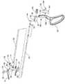
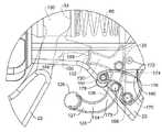
도 1은 본 발명에 따라 구성되고 구현되는 수술 기구의 등각투영도(isometric view)이고, 배럴의 원위 단부(distal end)에서 캐리어에 장착된 한 쌍의 이펙터 죠 및 상기 배럴의 근위 단부에서 핸들 섹션을 도시한다.
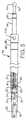
도 2는 상기 이펙터 죠를 폐쇄 및 개방하기 위한 구성 요소의 분해도이다.
도 3은 개방 위치에서 상기 이펙터 죠를 도시하는 수술 기구의 일부를 통한 부분 단면도이다.
도 4는 그의 측면도이다.
도 5는 폐쇄 위치에서 상기 이펙터 죠를 도시하는 수술 기구의 일부를 통한 부분 단면도이다.
도 6은 상기 죠가 닫힌 위치에 있는 측면도이다.
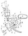
도 7은 상기 이펙터 죠의 의도하지 않은 작동을 자동으로 배제하기 위한 방향으로 안전 장치에 의하여 상기 이펙터 죠를 폐쇄 및 개방하기 위한 핸들 섹션 구성 요소의 분해도이다.
도 8은 상기 이펙터 죠의 반복적인 작동을 허용하는 잠금 해제된 방향으로 안전 장치에 의하여 상기 이펙터 죠를 폐쇄 및 개방하기 위한 핸들 섹션 구성 요소의 분해도이다.
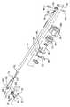
도 9는 캐리어의 관절(articulation)을 위한 구성 요소의 분해도이다.
도 10은 도 4와 유사하고 상기 배럴과 동축인 캐리어를 도시하는 수술 기구의 일부를 통한 부분 단면도이다.
도 11은 수술 기구의 일부를 통한 부분 단면도로서, 관절 연결된 위치(articulated position)에서 상기 캐리어를 도시한다.
도 12는 상기 배럴의 축 회전을 위한 구성 요소의 분해도이다.
도 13은 상기 안전 장치가 자동 잠금 위치에 있는 수술 기구의 부분 측면도이다.
도 14는 도 13에 동그라미 표시된 부분의 확대도이다.
도 15는 상기 안전 장치가 잠금 해제된 수술 기구의 부분 측면도이다.
도 16은 도 15에 동그라미 표시된 부분의 확대도이다.In the accompanying drawings, one of various possible exemplary embodiments of the invention is shown.
1 is an isometric view of a surgical instrument constructed and implemented in accordance with the present invention, a pair of effector jaws mounted to a carrier at the distal end of the barrel and a handle section at the proximal end of the barrel; show
2 is an exploded view of components for closing and opening the effector jaw;
3 is a partial cross-sectional view through a portion of a surgical instrument showing the effector jaw in an open position;
4 is a side view thereof;
5 is a partial cross-sectional view through a portion of a surgical instrument showing the effector jaw in a closed position.
6 is a side view with the jaws in a closed position;
7 is an exploded view of a handle section component for closing and opening the effector jaws by means of a safety device in a direction for automatically precluding unintentional actuation of the effector jaws;
8 is an exploded view of a handle section component for closing and opening the effector jaws by means of a safety device in an unlocked orientation allowing for repeated actuation of the effector jaws;
9 is an exploded view of a component for articulation of a carrier;
FIG. 10 is a partial cross-sectional view through a portion of a surgical instrument similar to FIG. 4 and showing the carrier coaxial with the barrel.
11 is a partial cross-sectional view through a portion of a surgical instrument, showing the carrier in an articulated position;
12 is an exploded view of components for axial rotation of the barrel;
13 is a partial side view of a surgical instrument with the safety device in a self-locking position.
14 is an enlarged view of a portion indicated by a circle in FIG. 13 .
15 is a partial side view of a surgical instrument with the safety device unlocked;
16 is an enlarged view of a portion indicated by a circle in FIG. 15 .
본 발명은 이제 당업자가 본 발명을 실시할 수 있도록 본 발명의 예시적인 예로서 제공되는 도면을 참조하여 상세하게 설명될 것이다. 특히, 이하의 도면 및 실시 예는 본 발명의 범위를 단일 실시 예로 제한하려는 것이 아니며, 설명되거나 예시된 요소의 일부 또는 전부의 상호 교환에 의해 다른 실시 예가 가능하다.The present invention will now be described in detail with reference to the drawings, which are provided as illustrative examples of the invention to enable those skilled in the art to practice the invention. In particular, the following drawings and examples are not intended to limit the scope of the present invention to a single embodiment, but other embodiments are possible by the interchange of some or all of the elements described or illustrated.
출원인은 본 명세서 또는 청구 범위의 임의의 용어가 명시적으로 언급되지 않는 한, 흔하지 않거나 특별한 의미를 갖는 것을 의도하지 않는다. 또한, 본 발명은 예시로서 본 명세서에 언급된 공지된 구성 요소와 현재 및 미래의 알려진 등가물을 포함한다.Applicants do not intend for any term in the specification or claims to have an uncommon or special meaning unless explicitly recited. Furthermore, the present invention includes, by way of illustration, known components referred to herein as well as present and future known equivalents.
이제 도면을 참조하면, 참조 번호 10은 본 발명에 따라 구성되고 본 발명을 구현하는 수술 기구(surgical appliance)를 나타내며 중합체 결찰 클립(polymeric ligation clip)을 적용하는 것과 같은 절차에 사용될 수 있다. 상기 기구(10)는 근위 핸들 섹션(proximal handle section)(12), 길이 방향 축(15)을 따라 연장되는 중공 원통형 메인 배럴(hollow cylindrical main barrel)(14) 및 한 쌍의 이펙터 죠(18, 20)를 운반하는 캐리어(16)를 포함한다. 핸들 섹션(12)은 그립(grip)(22), 스톡(stock)(23), 관절 노브(articulation knob)(24) 및 배럴 회전 노브(barrel rotation knob)(26)를 포함하고, 이들 모두는 예를 들어 한 손 조작을 위해 서로 근접한 관계로 위치되고, 즉 실무자의 손바닥에 상기 스톡(23)을 올려놓은 상태에서 실무자의 손가락으로 그립(22)을 압박(squeezing)하고 풀고(releasing) 실무자의 엄지 및/또는 집게 손가락(forefinger)으로 상기 노브(24, 26)를 회전시킨다.Referring now to the drawings,
도 2를 참조하면, 상기 죠(18, 20)는 롤러 체인의 단일 링크와 유사한 링크(29)로 로드(32)의 단부에 연결된 터미널 클레비스(terminal clevis)(30)를 통해 작동된다. 저널(journal)(41)은 한 쌍의 측면 패널(35)의 근위 개구부(proximal aperture)를 통해 상기 로드(32)의 원위 단부로부터 돌출하고 핀(43)은 측면 패널의 원위 개구부 및 클레비스 플랜지(clevis flange)(45)의 개구부를 통해 연장된다. 추가 핀(34)은 상기 클레비스(30)의 대향면(opposed faces)을 통해 연장되고 각각 죠(18, 20)에서 만곡된 캠 슬롯(curved cam slot)(36, 37)과 결합한다. 도 9에 도시된 바와 같이, 클레비스(30) 및 로드(32)의 선형 이동에 따라, 상기 죠(18, 20)는 상기 캐리어(16)의 요크(yoke)(40)를 통해 연장되는 핀(38) 주위로 피벗된다. 상기 죠(18, 20)의 일부는 상기 요크(40) 내에 수용된다.Referring to Figure 2, the
상기 로드(32)의 근위 단부(proximal end)는 그의 근위 단부에서 볼(44)을 포함하는 견인바(drawbar)(42)의 원위 단부(distal end)에 고정된다. 원통형 선형 액추에이터(46)는 핸들 섹션(12)의 중공 케이싱(47) 내에 수용되며, 상기 볼(44)이 수용되는 소켓(48)을 포함한다. 상기 그립(22)의 기본 레그(50)는 3개의 패널(150, 152 및 154)의 용접 라미네이트(welded laminate) 및 상기 선형 액추에이터(46)의 슬롯(52)에 수용되는 캠 표면(54)을 포함한다. 도 7을 참조하면, 상기 그립(22)이 상기 스톡(23)을 향해 압착될 때, 1차 레그(50)는 상기 핸들 섹션(12)의 개구부(62)에 고정된 핀(56)을 중심으로 회전하며, 이는 상기 선형 액추에이터(46) 및 상기 볼(44)이 축(15)을 따라 근위 방향(proximal direction)으로 이동하게 하여 리턴 스프링(return spring)(60)을 압축시킨다.The proximal end of the
동시에, 상기 견인바(42), 상기 로드(32) 및 상기 터미널 클레비스(30)는 상기 근위 단부를 향해 이동하여, 아는 이펙터 죠(18, 20)가 도 3에 도시된 정상 개방 위치로부터 도 5에 도시된 폐쇄 위치로 이동하게 한다.At the same time, the
이제 도 9를 참조하면, 상기 캐리어(16)의 관절 구성 요소가 도시되어 있고, 상기 캐리어(16)는 헤드 슬리브(68)에 형성된 채널(66)의 평행에 이격된 벽(63) 사이에 수용되는 이격된 평행 패널(65)을 포함하는 감소된 두께의 근위 채널 플랜지(proximal channel flange)(64)를 포함한다. 저널(70)은 각 패널(65)로부터 돌출되어 상기 채널 벽(63)의 개구부(72)에 안착된다. 상기 헤드 슬리브(68)는 배럴(14)의 원위 단부에 안착된다.Referring now to FIG. 9 , the articulating component of the
상기 저널(70)과 동심(concentric with)인 회전축(71)에 대한 상기 캐리어(16)의 관절(Articulation)은 상기 배럴(14)을 통해 연장되는 중공 태핏(hollow tappet)(74)의 왕복 축 운동(reciprocal axial movement)을 통해 영향을 받는다. 상기 태핏(74)의 원위 단부로부터 연장되는 레그(75)의 단부는 상기 패널(65) 사이에 수용된다. 핀(73)은 상기 패널(65)의 오프셋 개구부(79) 및 상기 레그(75)의 단부(end portion)를 통해 연장된다. 따라서, 상기 태핏(74)의 축 방향 이동은 상기 저널(70)에 대한 캐리어(16)의 관절에 영향을 준다. 상기 중공 태핏(74)을 통한 연장은 상기 견인바(42)이며, 한 쌍의 개스킷 시일(gasket seal)(45)은 상기 견인바(42)와 상기 태핏(74) 사이에 제공된다.Articulation of the
도 9에 도시된 바와 같이, 상기 관절 노브(articulation knob)(24)의 회전은 나선 채널(77)을 갖는 원통형 캠(76)을 회전시킴으로써 상기 태핏(74)의 축 방향 운동으로 바뀐다(translate). 상기 캠(76)은 상기 선형 액추에이터(46)의 원위 단부에 끼워지는 칼라(collar)(78) 위에 안착된다. 상기 칼라(78)는 대응하는 홈(grooves)(84)에 안착되는 한 쌍의 클립(82)에 의해 상대 축 방향 이동에 대해 상기 태핏(74)에 고정되는 링(80) 위에 장착된다. 한 쌍의 정반대(diametrically opposed) 캠 팔로워(cam follower)(86)는 상기 링(80)에 고정되고 상기 캠(76)의 상기 나선 채널(77)과 결합한다.As shown in FIG. 9 , rotation of the
상기 팔로워(86)는 또한 상기 칼라(78)의 한 쌍의 정반대 채널(87)로 연장된다. 따라서, 상기 캠 팔로워(86)와 원통형 캠(76) 사이의 결합(engagement)을 통해, 상기 관절 노브(24)의 회전은 상기 태핏(74)의 축 방향 이동 및 상기 저널(70)의 축에 대한 상기 캐리어(16)의 피벗 운동을 초래한다.The
상기 관절 노브(24)에는 상기 노브(24)와 함께 회전하는 내부 기어(88)가 장착되어 있다. 상기 노브(24)의 회전시, 상기 기어(88)의 톱니는 상기 칼라(78)의 정 반대 소켓에 안착된 한 쌍의 볼 디텐트 래치(ball detent latches)(90)에 의해 결합되어 항복가능하고(yieldable) 및 가청 가능한(audible) 한계 스톱으로 회전을 증가시킨다(to increment rotation with yieldable and audible limit stops).The
체강 내에서의 기동성(maneuverability)을 증가시키기 위해, 상기 이펙터 죠(18, 20) 및 캐리어(16)의 치수는 이상적으로 최소화된다. 예를 들어, 원위 팁(distal tip)으로부터 상기 피벗 핀(38)의 중심까지의 각각의 이펙터 죠의 길이는 29mm 정도(in the order of)이며 상기 캐리어(16)는 최대 50°의 오프셋 각도로 연결되며, 도 10에 도시된 바와 같이, 상기 캐리어 피벗 핀(70)의 중심으로부터 상기 이펙터 죠(18, 20)의 원위 팁까지의 개방 위치에서의 거리는 50mm 정도일 것이다.To increase maneuverability within the body cavity, the dimensions of the
이제 도 12를 참조하면, 상기 배럴(14)의 근위 단부에 안착되고 고정된 것은 계단형 칼라(stepped collar)(92)의 감소된 직경의 목(reduced diameter neck)(94)이다. 중간 직경 부분(96)의 숄더(shoulder)는 상기 배럴(14)의 근위 단부에 인접한다. 상기 칼라(92)의 더 큰 직경의 근위 부분(98)은 메인 슬리브(100)의 보어(bore) 내에 수용된다. 상기 메인 슬리브 보어(main sleeve bore) 내에는 트랜지션 슬리브(transition sleeve)(102)가 위치하고, 상기 칼라(92)의 근위 단부에 인접하는 개스킷(104)과 상기 슬리브(102) 위에 위치한 추가 개스킷(106)이 있다. 조립될 때, 플러싱 통로(flushing passage)는 상기 배럴 노브(26), 계단 형 칼라(92) 및 메인 슬리브(100)에서 각각 등록된 개구부(108, 110 및 112)를 통해 제공된다. 플러싱 스피곳 조립체(flushing spigot assembly)(115)는 상기 배럴 노브 개구부(108)에 장착된다.Referring now to FIG. 12 , seated and secured to the proximal end of the
상기 메인 슬리브 보어(100)의 근위 단부에는 가스켓(114), 링 기어(118) 및 터미널 칼라(terminal collar)(120)가 안착된다. 또한, 상기 배럴 회전 노브(26), 상기 계단형 칼라(92) 및 상기 메인 슬리브(100)가 동시에 회전할 때 상기 터미널 칼라(120) 및 링 기어(118)는 문방구로 남는다(remain stationery). 상기 메인 슬리브(100)의 회전시, 상기 링 기어(118)의 톱니는 상기 메인 슬리브(100)의 소켓(119)에 안착된 볼 디텐트 래치(122)에 의해 결합되어 항복가능하고 가청가능한 한계 스톱를 갖는(with yieldable and audible limit stops) 상기 배럴(14)의 회전을 증가시킨다.A
본 발명에 따라, 상기 이펙터 죠(18, 20)의 의도하지 않은 작동을 방지하기 위해 안전 장치가 제공된다. 도 7을 참조하면(여기서 핸들 섹션(12)의 그립(22)은 자동 잠금 위치에 도시됨), 잠금/해제 레버(124)는 일체형 암(127)의 원위 단부에 한 쌍의 널형(knurled) 핑거 바(126)를 포함한다. 상기 잠금/해제 레버(124)의 상부는 상기 스톡(stock)(23)의 중공 영역 내에 안착된다. 상기 잠금/해제 레버(124)는 상기 스톡(23)을 통해 연장되는 핀(128)을 중심으로 피벗하도록 구성된다.According to the present invention, a safety device is provided to prevent unintended actuation of the
상기 잠금/해제 레버(124)의 상부로부터 원위로(distally) 돌출하는 것은 오목한 접합 단부(concave abutment end)(132)를 포함하는 일체형 래치(integral latch)(130)이다. 상기 암(127)과 상기 래치(130)를 일체로 결합시키는 것은 원위면(distal face)(136)과 근위면(proximal face)(176)을 포함하는 바이트(bight)(134)이다. 상기 패널(154)은 인접 단부(abutment end)(158)를 포함하는 근접하게 돌출된 스트라이크 레그(strike leg)(156)를 포함한다는 점에 유의해야 한다.Protruding distally from the top of the lock/
좌측 토글 암(left side toggle arm)(160) 및 우측 토글 암(162)은 도 14에 도시된 자동 잠금 위치와 도 16에 도시된 잠금 해제 위치 사이에서 상기 핸들 섹션(12)의 대향면을 따라 회전하기 위해 캠 샤프트(164)의 대향 단부에 고정된다. 각각의 토글 암의 내부면은 볼 래치(168)를 수용하는 리세스(166)를 포함한다. 상기 볼 래치(168)는 잠금 위치에서 디텐트(170)에 그리고 상기 토글 암이 잠금 해제 위치에 있을 때 잠금 위치에 디텐트(172)에 안착된다. 상기 볼 래치가 상기 디텐트(170)에 안착될 때 정지 핀(173)은 상기 토글 암의 추가 회전을 방지한다.A left
도 14에 가장 잘 도시된 바와 같이, 상기 토글 암(160, 162)이 자동 잠금 위치에 있을 때, 상기 그립(22)은 각각의 인접 단부(132, 158) 사이의 맞댐 접촉(abutting contact)에 의해 근위 방향으로 이동하는 것이 방지된다. 스프링 장착 볼 조립체(174)는 상기 핸들 섹션(12)의 근위 단부에 안착되어 있고, 상기 바이트(bight)(134)의 근위면(176)에 대해 지지되고(bear), 상기 캠 샤프트(164)에 고정된 캠(178)은 상기 바이트(134)의 원위면(136)과 맞닿는다.As best shown in FIG. 14 , when the
의사는 널형 핑거바(knurled finger bars)(126)를 움켜쥐고 상기 스프링 장착 볼 조립체(174)의 바이어스에 대항하여 잠금/해제 레버(124)를 근위로 당겨서 그립(22)의 잠금을 해제할 수 있으며, 상기 잠금/해제 레버(124)가 상기 핀(128)을 중심으로 회전하게 하고, 이에 따라 상기 스트라이크 레그(156)는 더 이상 래치(130)와 정렬되지 않을 것이다. 그 후, 상기 그립(22)은 근위로 당겨져서 예를 들어 결찰 클립을 결합하거나 해제하기 위해 이펙터 죠(18, 20)가 개방되게 할 수 있다. 상기 널형 핑거 바(126)의 해제시, 상기 잠금/해제 레버(124)는 근위면(176)에 대한 스프링 볼 조립체(174)의 바이어스로 인해 도 14 위치로 복귀한다.The surgeon can unlock the
도 16에서, 상기 안전 장치(safety mechanism) 구성 요소가 분리되어 잠금/해제 레버(124)가 회전될 필요없이 상기 그립(22)이 당겨질 수 있는 것으로 도시되어 있다. 도 16에 도시된 바와 같이, 상기 안전 장치를 해제하기 위해, 상기 토글 암(160, 162)은 상기 볼 래치(168)가 상기 디텐트(172)에 안착될 때까지 (도 13 내지 15에 도시된 바와 같이) 캠 샤프트(164)와 함께 반 시계 방향으로 대략 90도 회전한다. 상기 캠 샤프트(164)의 회전은 상기 캠(178)이 원위면(136)에 대해 지지하고 상기 스프링 볼 조립체(174)의 바이어스에 대항하여 반 시계 방향으로 잠금/해제 레버(124)를 회전시키며, 여기서 상기 스트라이크 레그(156)는 더 이상 래치(130)와 정렬되지 않으며 상기 그립(22)은 수술 절차를 통해 반복적으로 자유롭게 작동될 수 있다.In FIG. 16 , the safety mechanism component is disengaged so that the
상기 상세한 실시 예에서의 요소 및 특징의 특정 조합은 단지 예시 일뿐; 이러한 교시와 본원의 다른 교시 및 참고 문헌으로 통합된 특허/출원과의 상호 교환 및 대체가 또한 명시적으로 고려된다. 당업자는 청구된 바와 같은 본 발명의 사상 및 범위를 벗어나지 않고 당업자에게 본원에 기재된 것의 변형, 수정 및 다른 구현이 가능하다는 것을 인식할 것이다.The specific combinations of elements and features in the above detailed embodiments are merely examples; Interchangeability and substitution of these teachings with other teachings herein and patents/applications incorporated by reference are also expressly contemplated. Those skilled in the art will recognize that variations, modifications, and other implementations of what is described herein are possible to those skilled in the art without departing from the spirit and scope of the invention as claimed.
본 발명의 예시적인 실시 예들을 설명하였지만, 당업자에게는 그들의 개념을 통합하는 다른 실시 예들도 또한 사용될 수 있음이 명백할 것이다. 또한, 여기에 기술된 본 발명의 실시 예가 본 명세서에 언급된 적용 가능한 기술 및 표준의 변경 및 개선을 수용 및/또는 준수하도록 수정될 수 있음을 당업자는 이해할 것이다.While exemplary embodiments of the present invention have been described, it will be apparent to those skilled in the art that other embodiments incorporating their concepts may also be used. In addition, it will be understood by those skilled in the art that the embodiments of the invention described herein may be modified to accommodate and/or comply with changes and improvements in the applicable technologies and standards referred to herein.
청구 범위에 기재된 본 발명의 사상 및 범위를 벗어나지 않고 본 명세서에 기재된 것에 대한 변형, 수정 및 다른 구현이 당업자에게 발생할 수 있다. 따라서, 이러한 실시 예들은 개시된 실시 예에 한정되어서는 안되며 오히려 첨부된 청구 범위의 사상 및 범위에 의해서만 한정되어야 한다.Variations, modifications and other implementations of what is described herein may occur to those skilled in the art without departing from the spirit and scope of the invention as set forth in the claims. Accordingly, these embodiments should not be limited to the disclosed embodiments, but rather should be limited only by the spirit and scope of the appended claims.
Claims (20)
Translated fromKoreanan elongated barrel, a carrier secured to the distal end of the barrel, an effector jaw mounted to the carrier, a rod or cable positioned within the barrel, the rod operatively connected to the effector jaw for opening and closing the effector jaw or a handle at the distal end of the cable, the proximal end of the barrel, the handle comprising a linear actuator, the distal end of the rod or cable operatively connected to the linear actuator, the linear actuator comprising a slot and wherein the handle further comprises a pivotally mounted grip, the grip comprising a primary leg, the primary leg being received in the slot, such that pivoting movement of the grip is associated with linear motion of the rod or cable effecting movement of the effector jaws relative to each other, the handle further comprising a barrel rotating knob and a sleeve, the barrel rotating knob, the barrel and the sleeve being coupled to rotate together, a ring gear received in the sleeve, the The ring gear is fixed with respect to rotation, and the handle further comprises a detent latch extending radially through the sleeve, the detent latch engaging the ring gear such that rotation of the barrel rotation knob is yieldable. Surgical instruments that increase with yieldable and audible limiting stops.
상기 핸들은 캐리어 관절 노브(carrier articulation knob) 및 그립의 우발적인 작동을 자동으로 방지하기 위한 안전 메커니즘을 포함하는 수술 기구.
According to claim 1,
wherein the handle includes a carrier articulation knob and a safety mechanism for automatically preventing accidental actuation of the grip.
상기 안전 메커니즘은 잠금 위치로부터 회전 가능한 레버를 포함하고, 여기서 상기 그립은 잠금 해제 위치로 회전하는 것이 불가능하고, 여기서 상기 그립이 회전하는 것을 배제하지 않고, 상기 안전 메커니즘은 잠금 위치를 향해 상기 레버를 편향시키는 스프링 요소를 더 포함하는 수술기구.
3. The method of claim 2,
wherein the safety mechanism includes a lever rotatable from a locked position, wherein the grip is unable to rotate to an unlocked position, wherein without precluding rotation of the grip, the safety mechanism moves the lever toward the locked position A surgical instrument further comprising a biasing spring element.
각각의 이펙터 죠는 캠 슬롯 및 상기 로드 또는 케이블의 원위 단부에 작동 가능하게 연결되는 핀을 포함하고, 상기 핀은 상기 캠 슬롯을 통해 횡 방향으로 연장되고, 따라서 상기 로드 또는 케이블의 선형 이동은 서로에 대해 상기 이펙터 죠를 이동시키는 수술 기구.
According to claim 1,
Each effector jaw includes a cam slot and a pin operatively connected to the distal end of the rod or cable, the pin extending transversely through the cam slot such that linear movement of the rod or cable is mutually exclusive. A surgical instrument for moving the effector jaws relative to each other.
상기 로드 또는 케이블의 원위 단부는 터미널 링크에 결합되고 상기 핀은 상기 터미널 링크의 대향면을 통해 연장되는 수술 기구.
5. The method of claim 4,
The distal end of the rod or cable is coupled to a terminal link and the pin extends through an opposite surface of the terminal link.
상기 이펙터 죠가 정상적으로 개방되도록 원위 방향으로 상기 상기 선형 액추에이터 및 로드 또는 케이블을 가압(urge)하기 위하여 상기 선형 액추에이터를 지지하는 리턴 스프링을 포함하는 수술 기구.
According to claim 1,
and a return spring supporting the linear actuator to urge the linear actuator and rod or cable in a distal direction such that the effector jaws are normally opened.
상기 기본 레그는 캠 표면을 갖는 패널의 라미네이트를 포함하고, 상기 캠 표면은 상기 슬롯에 수용되는 수술 기구.
According to claim 1,
wherein the base leg includes a laminate of panels having a cam surface, the cam surface being received in the slot.
상기 배럴, 상기 배럴 회전 노브, 상기 슬리브 및 상기 링 기어는 동축인 수술 기구.
According to claim 1,
wherein the barrel, the barrel rotation knob, the sleeve and the ring gear are coaxial.
An elongated barrel comprising an effector jaw mounted to a carrier secured to the distal end of the barrel, a cylindrical head sleeve bifurcated at the distal end of the barrel and a handle at the proximal end of the barrel, the distal end of the head sleeve a channel formed therein, wherein the channel comprises a pair of parallel walls, the carrier comprising a flange at its proximal end, the flange received between the parallel walls, the carrier comprising the head at an axis of rotation. and a tappet pivotally coupled to the sleeve and movable in an axial direction carried within the barrel, the tappet including a tappet leg pivotally connected to the flange at a point offset from the axis of rotation, the handle comprising: a ring having an articulation knob, a cylindrical cam, and at least one cam follower projecting radially therefrom, the ring mounted over a proximal end of the tappet, the ring adapted to axial movement relative to the tappet. and wherein the articulation knob and the cylindrical cam rotate in unison, the cylindrical cam positioned over the ring, such that rotation of the articulation knob and engagement between the channel and one or more cam followers is in the barrel. A surgical instrument that results in an axial movement of the tappet about an axis of rotation about the axis of rotation and articulation of the carrier.
상기 관절 노브에 안착되어 일제히 회전하는 내부 기어를 더 포함하고, 상기 관절 노브는 회전에 대해 고정된 칼라 위에 안착되고, 상기 칼라는 상기 내부 기어와 등록되고 맞물리는 적어도 하나의 볼 디텐트 래치를 포함하고, 따라서 회전 관절 노브의 회전은 항복가능하고(yieldable) 및 가청 가능한(audible) 한계 스톱으로 증가하는 수술 기구.
10. The method of claim 9,
and an internal gear seated on the articulation knob to rotate in unison, the articulation knob seated on a collar fixed against rotation, the collar comprising at least one ball detent latch registered and engaged with the internal gear and, thus, rotation of the rotary articulation knob increases to yieldable and audible limit stops.
상기 관절 노브, 원통형 캠, 링 및 태핏은 동축인 수술 기구.
10. The method of claim 9,
wherein said articulating knob, cylindrical cam, ring and tappet are coaxial.
A surgical instrument comprising an elongated barrel, an effector jaw positioned proximate the distal end of the barrel, a rod or cable positioned within the barrel, the rod or cable operatively connected to the effector jaw for opening and closing the effector jaw. a distal end, a handle at the proximal end of the barrel, the handle operatively connected to the proximal end of the rod or cable; and a safety mechanism for preventing accidental actuation of the grip from closing the effector jaws. wherein the grip is proximally rotatable to close the effector jaws, and wherein the safety mechanism comprises a lever rotatable in a locked position, wherein the grip is not proximally rotatable to an unlocked position, wherein The grip does not preclude rotation in the proximal direction, wherein the mechanism comprises a spring element biasing the lever toward a locked position and a surface of the lever to maintain the lever in the locked position against bias of the spring element. a cam rotatable to support, the surgical instrument further comprising a latch protruding distally from the lever, the grip comprising a strike leg protruding proximally, the latch engaging the strike leg a surgical instrument positioned to block and prevent rotation of the grip in a proximal direction when the lever is in the locked position.
상기 레버는 상기 잠금 위치에서 잠금 해제 위치로 상기 레버를 잡고 회전할 수 있는 핑거 바를 포함하고, 여기서 상기 그립은 작동될 수 있고, 상기 레버는 상기 스프링 요소의 편향 하에서 상기 잠금 위치로 복귀하는 수술 기구.
13. The method of claim 12,
wherein the lever includes a finger bar rotatable to grip and rotate the lever from the locked position to the unlocked position, wherein the grip is operable and the lever returns to the locked position under bias of the spring element. .
상기 캠은 샤프트에 고정되고 상기 샤프트의 단부는 토글 암에 고정되며, 상기 토글 암은 상기 캠이 상기 위치로 또는 위치로부터 회전하도록 회전되고, 여기서 상기 레버는 상기 핑거 바에 결합하지 않고 잠금 해제 위치에 놓이는 수술 기구.
14. The method of claim 13,
The cam is fixed to the shaft and the end of the shaft is secured to a toggle arm, the toggle arm rotated to rotate the cam into or out of the position, wherein the lever is in an unlocked position without engaging the finger bars. surgical instruments placed.
상기 샤프트의 반대 단부에 고정된 토글 암을 더 포함하고,
각각의 토글 암은 상기 레버 잠금 해제 위치에 대응하는 하나의 디텐트와 상기 레버 잠금 위치에 대응하는 또 다른 디텐트에 안착되는 볼 래치 메커니즘을 포함하는 수술 기구.
15. The method of claim 14,
a toggle arm fixed to an opposite end of the shaft;
wherein each toggle arm includes a ball latch mechanism seated in one detent corresponding to the lever unlock position and another detent corresponding to the lever lock position.
상기 그립은 패널 라미네이트를 포함하고, 상기 스트라이크 레그는 상기 패널 중 적어도 하나로부터 돌출되는 수술 기구.
13. The method of claim 12,
wherein the grip comprises a panel laminate and the strike leg protrudes from at least one of the panels.
상기 레버는 말단 돌출 암(distally projecting arm)을 포함하고, 상기 핑거 바는 상기 암의 단부에 위치하고 그로부터 측면으로(laterally) 돌출하고, 상기 레버는 상기 암 및 래치 사이에 펼쳐진 바이트를 더 포함하는 수술 기구.
14. The method of claim 13,
wherein the lever includes a distally projecting arm, the finger bar is positioned at an end of the arm and projects laterally therefrom, the lever further comprising a bite spread between the arm and the latch machine.
상기 바이트는 근위면과 원위면을 포함하고, 상기 스프링 요소는 상기 근위면과 결합하고 상기 캠은 원위면과 결합하는 수술 기구.
18. The method of claim 17,
The bite comprises a proximal surface and a distal surface, wherein the spring element engages the proximal surface and the cam engages the distal surface.
Applications Claiming Priority (3)
| Application Number | Priority Date | Filing Date | Title |
|---|---|---|---|
| US201762581729P | 2017-11-05 | 2017-11-05 | |
| US62/581,729 | 2017-11-05 | ||
| PCT/US2018/057439WO2019089331A1 (en) | 2017-11-05 | 2018-10-25 | Surgical appliance |
Publications (2)
| Publication Number | Publication Date |
|---|---|
| KR20200085793A KR20200085793A (en) | 2020-07-15 |
| KR102449277B1true KR102449277B1 (en) | 2022-09-29 |
Family
ID=66326505
Family Applications (1)
| Application Number | Title | Priority Date | Filing Date |
|---|---|---|---|
| KR1020207015452AActiveKR102449277B1 (en) | 2017-11-05 | 2018-10-25 | surgical instruments |
Country Status (8)
| Country | Link |
|---|---|
| US (1) | US10918393B2 (en) |
| EP (1) | EP3703588B1 (en) |
| JP (3) | JP7443231B2 (en) |
| KR (1) | KR102449277B1 (en) |
| CN (2) | CN118986457A (en) |
| PL (1) | PL3703588T3 (en) |
| RU (1) | RU2761389C1 (en) |
| WO (1) | WO2019089331A1 (en) |
Families Citing this family (16)
| Publication number | Priority date | Publication date | Assignee | Title |
|---|---|---|---|---|
| US10709517B2 (en)* | 2018-01-16 | 2020-07-14 | Multi Scopic Instruments, Llc | End effector |
| US11950871B2 (en)* | 2018-01-16 | 2024-04-09 | Multi Scopic Instruments, Llc | End effector |
| CN109480951B (en)* | 2018-12-29 | 2024-01-12 | 杭州圣石科技股份有限公司 | Disassembly-free flushable clip applier |
| CN110215258B (en)* | 2019-07-17 | 2024-11-01 | 山东威瑞外科医用制品有限公司 | Clamp applier |
| CN110522489A (en)* | 2019-09-29 | 2019-12-03 | 山东威瑞外科医用制品有限公司 | A kind of Clip Applier instrument |
| PL239734B1 (en)* | 2019-12-27 | 2022-01-03 | Konmex Spolka Z Ograniczona Odpowiedzialnoscia | Laparoscopic instrument |
| US11344302B2 (en)* | 2020-03-05 | 2022-05-31 | Covidien Lp | Articulation mechanism for surgical stapling device |
| WO2021257520A1 (en) | 2020-06-16 | 2021-12-23 | Grena Usa Llc | Grip force attenuator |
| WO2022077004A1 (en)* | 2020-10-07 | 2022-04-14 | Kelly Robert A | Arthroscopic surgical tool for manipulating bony tissue |
| CN112807089B (en)* | 2021-02-10 | 2022-05-03 | 诺创智能医疗科技(杭州)有限公司 | Surgical Instruments and Surgical Robots |
| WO2022170795A1 (en)* | 2021-02-10 | 2022-08-18 | 诺创智能医疗科技(杭州)有限公司 | Surgical instrument and control method therefor, surgical robot and electronic device |
| CN113693712B (en)* | 2021-08-30 | 2022-09-13 | 浙江微度医疗器械有限公司 | Electric coagulation cutting instrument with double operating handles |
| EP4295783A3 (en)* | 2022-06-02 | 2024-02-28 | William J. Zinnanti | Modular forceps |
| CN115381541B (en)* | 2022-08-31 | 2024-07-30 | 郝定均 | Integrated anterior cervical restorer |
| CN117159058A (en)* | 2023-09-05 | 2023-12-05 | 南京思脉德医疗科技有限公司 | A kind of pull button structure and suturing device |
| US20250127506A1 (en)* | 2023-10-24 | 2025-04-24 | Astron Medtech Corporation | Surgical device |
Citations (2)
| Publication number | Priority date | Publication date | Assignee | Title |
|---|---|---|---|---|
| US20080223903A1 (en) | 2007-03-15 | 2008-09-18 | Stanislaw Marczyk | Surgical stapling apparatus with powered articulation |
| US20090088792A1 (en) | 2007-10-02 | 2009-04-02 | Tyco Healthcare Group Lp | Articulating Surgical Instrument |
Family Cites Families (29)
| Publication number | Priority date | Publication date | Assignee | Title |
|---|---|---|---|---|
| US2790437A (en)* | 1955-10-12 | 1957-04-30 | Welch Allyn Inc | Surgical instrument |
| CA1182709A (en)* | 1981-09-03 | 1985-02-19 | Kent R. Struble | Stapler |
| AU3656993A (en)* | 1992-02-07 | 1993-09-03 | Symbiosis Corporation | Endoscopic surgical instruments having stepped rotatable end effectors |
| US5314424A (en)* | 1992-04-06 | 1994-05-24 | United States Surgical Corporation | Surgical instrument locking mechanism |
| US5290308A (en) | 1992-07-15 | 1994-03-01 | Edward Weck Incorporated | Endoscopic instrument |
| CA2106039A1 (en) | 1992-09-23 | 1994-03-24 | David A. Nicholas | Surgical biopsy forceps apparatus |
| US5330502A (en) | 1992-10-09 | 1994-07-19 | Ethicon, Inc. | Rotational endoscopic mechanism with jointed drive mechanism |
| US5431323A (en) | 1992-10-09 | 1995-07-11 | Ethicon, Inc. | Endoscopic surgical instrument with pivotable and rotatable staple cartridge |
| DE4307539B4 (en)* | 1993-03-10 | 2005-08-25 | Karl Storz Gmbh & Co. Kg | Medical forceps |
| US6019780A (en) | 1996-12-17 | 2000-02-01 | Tnco, Inc. | Dual pin and groove pivot for micro-instrument |
| JPH10277050A (en)* | 1997-04-04 | 1998-10-20 | Olympus Optical Co Ltd | High-frequency treating implement for endscope |
| US5893835A (en)* | 1997-10-10 | 1999-04-13 | Ethicon Endo-Surgery, Inc. | Ultrasonic clamp coagulator apparatus having dual rotational positioning |
| DE19935042B4 (en) | 1999-07-26 | 2004-02-05 | Aesculap Ag & Co. Kg | Surgical tubular shaft instrument |
| US6679874B2 (en) | 2001-10-05 | 2004-01-20 | Weck Closure Systems, Inc. | Ratcheting mechanism for endoscopic instruments |
| US6733514B2 (en) | 2001-10-05 | 2004-05-11 | Pilling Weck Incorporated | Jaw assembly for endoscopic instruments |
| NO322695B1 (en) | 2004-12-29 | 2006-11-27 | Surgitech Norway As | Instrument especially for use in laparoscopic surgical procedure |
| US7766910B2 (en) | 2006-01-24 | 2010-08-03 | Tyco Healthcare Group Lp | Vessel sealer and divider for large tissue structures |
| JP5481194B2 (en) | 2006-10-05 | 2014-04-23 | コヴィディエン リミテッド パートナーシップ | Flexible endoscopic suturing device |
| US7673782B2 (en)* | 2007-03-15 | 2010-03-09 | Ethicon Endo-Surgery, Inc. | Surgical stapling instrument having a releasable buttress material |
| US8628545B2 (en) | 2008-06-13 | 2014-01-14 | Covidien Lp | Endoscopic stitching devices |
| US8545519B2 (en) | 2009-12-22 | 2013-10-01 | Cook Medical Technologies Llc | Medical devices with detachable pivotable jaws |
| AU2014218433A1 (en) | 2010-02-25 | 2014-09-18 | Covidien Lp | Articulating endoscopic surgical clip applier |
| AU2014277777A1 (en) | 2010-07-28 | 2015-01-22 | Covidien Lp | Articulating clip applier |
| US8403946B2 (en) | 2010-07-28 | 2013-03-26 | Covidien Lp | Articulating clip applier cartridge |
| US8968337B2 (en) | 2010-07-28 | 2015-03-03 | Covidien Lp | Articulating clip applier |
| US9820765B2 (en) | 2012-05-01 | 2017-11-21 | Covidien Lp | Surgical instrument with stamped double-flange jaws |
| US8986330B2 (en) | 2013-07-12 | 2015-03-24 | Miami Instruments Llc | Aortic cross clamp |
| US9220508B2 (en) | 2013-09-06 | 2015-12-29 | Ethicon Endo-Surgery, Inc. | Surgical clip applier with articulation section |
| US10201381B2 (en) | 2015-06-11 | 2019-02-12 | Conmed Corporation | Hand instruments with shaped shafts for use in laparoscopic surgery |
- 2018
- 2018-10-24USUS16/169,681patent/US10918393B2/enactiveActive
- 2018-10-25PLPL18874260.5Tpatent/PL3703588T3/enunknown
- 2018-10-25EPEP18874260.5Apatent/EP3703588B1/enactiveActive
- 2018-10-25JPJP2020524495Apatent/JP7443231B2/enactiveActive
- 2018-10-25RURU2020114730Apatent/RU2761389C1/enactive
- 2018-10-25KRKR1020207015452Apatent/KR102449277B1/enactiveActive
- 2018-10-25CNCN202411128910.8Apatent/CN118986457A/enactivePending
- 2018-10-25WOPCT/US2018/057439patent/WO2019089331A1/ennot_activeCeased
- 2018-10-25CNCN201880071052.4Apatent/CN111295144B/enactiveActive
- 2023
- 2023-11-08JPJP2023190513Apatent/JP7680516B2/enactiveActive
- 2025
- 2025-02-17JPJP2025023018Apatent/JP2025072642A/enactivePending
Patent Citations (2)
| Publication number | Priority date | Publication date | Assignee | Title |
|---|---|---|---|---|
| US20080223903A1 (en) | 2007-03-15 | 2008-09-18 | Stanislaw Marczyk | Surgical stapling apparatus with powered articulation |
| US20090088792A1 (en) | 2007-10-02 | 2009-04-02 | Tyco Healthcare Group Lp | Articulating Surgical Instrument |
Also Published As
| Publication number | Publication date |
|---|---|
| CN118986457A (en) | 2024-11-22 |
| PL3703588T3 (en) | 2024-07-22 |
| JP7680516B2 (en) | 2025-05-20 |
| JP7443231B2 (en) | 2024-03-05 |
| US20190133596A1 (en) | 2019-05-09 |
| JP2021501650A (en) | 2021-01-21 |
| EP3703588A1 (en) | 2020-09-09 |
| WO2019089331A1 (en) | 2019-05-09 |
| US10918393B2 (en) | 2021-02-16 |
| EP3703588B1 (en) | 2024-04-17 |
| KR20200085793A (en) | 2020-07-15 |
| CN111295144A (en) | 2020-06-16 |
| CN111295144B (en) | 2024-09-06 |
| JP2024016191A (en) | 2024-02-06 |
| JP2025072642A (en) | 2025-05-09 |
| EP3703588A4 (en) | 2021-12-08 |
| RU2761389C1 (en) | 2021-12-07 |
Similar Documents
| Publication | Publication Date | Title |
|---|---|---|
| KR102449277B1 (en) | surgical instruments | |
| EP3560442B1 (en) | Surgical clip applier | |
| US6280458B1 (en) | Surgical grasping and holding forceps | |
| US8591523B2 (en) | Mid-point lock suture cutter | |
| CA2680258C (en) | Improved end effector mechanism for a surgical instrument | |
| US20190321048A1 (en) | End effector assemblies, drive sleeves, and surgical clip appliers incorporating the same | |
| JP5611843B2 (en) | Handle for surgical instrument and surgical instrument assembly | |
| US20060079933A1 (en) | Latching mechanism for forceps | |
| US20060190035A1 (en) | Latching mechanism for forceps | |
| CN102271596A (en) | Surgical Instruments, Surgical Instrument Handles, and Surgical Instrument Systems | |
| US10314565B2 (en) | Surgical device having actuator biasing and locking features | |
| JP2006341111A (en) | Surgical device with malleable shaft | |
| US10342560B2 (en) | Medical instrument | |
| EP2840980B1 (en) | Toggling ergonomic surgical instrument | |
| HK40031565A (en) | Surgical appliance | |
| US20040220601A1 (en) | Medical instrument | |
| US9566081B2 (en) | Actuation grip for a microsurgical instrument, and microsurgical instrument | |
| US20250082340A1 (en) | Medical instrument |
Legal Events
| Date | Code | Title | Description |
|---|---|---|---|
| PA0105 | International application | St.27 status event code:A-0-1-A10-A15-nap-PA0105 | |
| PG1501 | Laying open of application | St.27 status event code:A-1-1-Q10-Q12-nap-PG1501 | |
| E13-X000 | Pre-grant limitation requested | St.27 status event code:A-2-3-E10-E13-lim-X000 | |
| P11-X000 | Amendment of application requested | St.27 status event code:A-2-2-P10-P11-nap-X000 | |
| P13-X000 | Application amended | St.27 status event code:A-2-2-P10-P13-nap-X000 | |
| PA0201 | Request for examination | St.27 status event code:A-1-2-D10-D11-exm-PA0201 | |
| PA0302 | Request for accelerated examination | St.27 status event code:A-1-2-D10-D17-exm-PA0302 St.27 status event code:A-1-2-D10-D16-exm-PA0302 | |
| P11-X000 | Amendment of application requested | St.27 status event code:A-2-2-P10-P11-nap-X000 | |
| P13-X000 | Application amended | St.27 status event code:A-2-2-P10-P13-nap-X000 | |
| P11-X000 | Amendment of application requested | St.27 status event code:A-2-2-P10-P11-nap-X000 | |
| P13-X000 | Application amended | St.27 status event code:A-2-2-P10-P13-nap-X000 | |
| P11-X000 | Amendment of application requested | St.27 status event code:A-2-2-P10-P11-nap-X000 | |
| P13-X000 | Application amended | St.27 status event code:A-2-2-P10-P13-nap-X000 | |
| E902 | Notification of reason for refusal | ||
| PE0902 | Notice of grounds for rejection | St.27 status event code:A-1-2-D10-D21-exm-PE0902 | |
| T11-X000 | Administrative time limit extension requested | St.27 status event code:U-3-3-T10-T11-oth-X000 | |
| P11-X000 | Amendment of application requested | St.27 status event code:A-2-2-P10-P11-nap-X000 | |
| P13-X000 | Application amended | St.27 status event code:A-2-2-P10-P13-nap-X000 | |
| P11-X000 | Amendment of application requested | St.27 status event code:A-2-2-P10-P11-nap-X000 | |
| P13-X000 | Application amended | St.27 status event code:A-2-2-P10-P13-nap-X000 | |
| T11-X000 | Administrative time limit extension requested | St.27 status event code:U-3-3-T10-T11-oth-X000 | |
| T12-X000 | Administrative time limit extension not granted | St.27 status event code:U-3-3-T10-T12-oth-X000 | |
| E701 | Decision to grant or registration of patent right | ||
| PE0701 | Decision of registration | St.27 status event code:A-1-2-D10-D22-exm-PE0701 | |
| GRNT | Written decision to grant | ||
| PR0701 | Registration of establishment | St.27 status event code:A-2-4-F10-F11-exm-PR0701 | |
| PR1002 | Payment of registration fee | St.27 status event code:A-2-2-U10-U12-oth-PR1002 Fee payment year number:1 | |
| PG1601 | Publication of registration | St.27 status event code:A-4-4-Q10-Q13-nap-PG1601 | |
| PR1001 | Payment of annual fee | St.27 status event code:A-4-4-U10-U11-oth-PR1001 Fee payment year number:4 |