KR102449247B1 - Insertion Module and Insertion Device Having Insertion Module - Google Patents
Insertion Module and Insertion Device Having Insertion ModuleDownload PDFInfo
- Publication number
- KR102449247B1 KR102449247B1KR1020200097023AKR20200097023AKR102449247B1KR 102449247 B1KR102449247 B1KR 102449247B1KR 1020200097023 AKR1020200097023 AKR 1020200097023AKR 20200097023 AKR20200097023 AKR 20200097023AKR 102449247 B1KR102449247 B1KR 102449247B1
- Authority
- KR
- South Korea
- Prior art keywords
- sheet
- auxiliary
- sliding grooves
- wing
- seat
- Prior art date
- Legal status (The legal status is an assumption and is not a legal conclusion. Google has not performed a legal analysis and makes no representation as to the accuracy of the status listed.)
- Active
Links
Images


Classifications
- A—HUMAN NECESSITIES
- A61—MEDICAL OR VETERINARY SCIENCE; HYGIENE
- A61B—DIAGNOSIS; SURGERY; IDENTIFICATION
- A61B5/00—Measuring for diagnostic purposes; Identification of persons
- A61B5/145—Measuring characteristics of blood in vivo, e.g. gas concentration or pH-value ; Measuring characteristics of body fluids or tissues, e.g. interstitial fluid or cerebral tissue
- A61B5/14507—Measuring characteristics of blood in vivo, e.g. gas concentration or pH-value ; Measuring characteristics of body fluids or tissues, e.g. interstitial fluid or cerebral tissue specially adapted for measuring characteristics of body fluids other than blood
- A61B5/1451—Measuring characteristics of blood in vivo, e.g. gas concentration or pH-value ; Measuring characteristics of body fluids or tissues, e.g. interstitial fluid or cerebral tissue specially adapted for measuring characteristics of body fluids other than blood for interstitial fluid
- A—HUMAN NECESSITIES
- A61—MEDICAL OR VETERINARY SCIENCE; HYGIENE
- A61B—DIAGNOSIS; SURGERY; IDENTIFICATION
- A61B5/00—Measuring for diagnostic purposes; Identification of persons
- A61B5/145—Measuring characteristics of blood in vivo, e.g. gas concentration or pH-value ; Measuring characteristics of body fluids or tissues, e.g. interstitial fluid or cerebral tissue
- A61B5/14503—Measuring characteristics of blood in vivo, e.g. gas concentration or pH-value ; Measuring characteristics of body fluids or tissues, e.g. interstitial fluid or cerebral tissue invasive, e.g. introduced into the body by a catheter or needle or using implanted sensors
- A—HUMAN NECESSITIES
- A61—MEDICAL OR VETERINARY SCIENCE; HYGIENE
- A61B—DIAGNOSIS; SURGERY; IDENTIFICATION
- A61B5/00—Measuring for diagnostic purposes; Identification of persons
- A61B5/0002—Remote monitoring of patients using telemetry, e.g. transmission of vital signals via a communication network
- A61B5/0004—Remote monitoring of patients using telemetry, e.g. transmission of vital signals via a communication network characterised by the type of physiological signal transmitted
- A—HUMAN NECESSITIES
- A61—MEDICAL OR VETERINARY SCIENCE; HYGIENE
- A61B—DIAGNOSIS; SURGERY; IDENTIFICATION
- A61B5/00—Measuring for diagnostic purposes; Identification of persons
- A61B5/145—Measuring characteristics of blood in vivo, e.g. gas concentration or pH-value ; Measuring characteristics of body fluids or tissues, e.g. interstitial fluid or cerebral tissue
- A61B5/14532—Measuring characteristics of blood in vivo, e.g. gas concentration or pH-value ; Measuring characteristics of body fluids or tissues, e.g. interstitial fluid or cerebral tissue for measuring glucose, e.g. by tissue impedance measurement
- A—HUMAN NECESSITIES
- A61—MEDICAL OR VETERINARY SCIENCE; HYGIENE
- A61B—DIAGNOSIS; SURGERY; IDENTIFICATION
- A61B5/00—Measuring for diagnostic purposes; Identification of persons
- A61B5/145—Measuring characteristics of blood in vivo, e.g. gas concentration or pH-value ; Measuring characteristics of body fluids or tissues, e.g. interstitial fluid or cerebral tissue
- A61B5/14546—Measuring characteristics of blood in vivo, e.g. gas concentration or pH-value ; Measuring characteristics of body fluids or tissues, e.g. interstitial fluid or cerebral tissue for measuring analytes not otherwise provided for, e.g. ions, cytochromes
- A—HUMAN NECESSITIES
- A61—MEDICAL OR VETERINARY SCIENCE; HYGIENE
- A61B—DIAGNOSIS; SURGERY; IDENTIFICATION
- A61B5/00—Measuring for diagnostic purposes; Identification of persons
- A61B5/145—Measuring characteristics of blood in vivo, e.g. gas concentration or pH-value ; Measuring characteristics of body fluids or tissues, e.g. interstitial fluid or cerebral tissue
- A61B5/1468—Measuring characteristics of blood in vivo, e.g. gas concentration or pH-value ; Measuring characteristics of body fluids or tissues, e.g. interstitial fluid or cerebral tissue using chemical or electrochemical methods, e.g. by polarographic means
- A61B5/1486—Measuring characteristics of blood in vivo, e.g. gas concentration or pH-value ; Measuring characteristics of body fluids or tissues, e.g. interstitial fluid or cerebral tissue using chemical or electrochemical methods, e.g. by polarographic means using enzyme electrodes, e.g. with immobilised oxidase
- A61B5/14865—Measuring characteristics of blood in vivo, e.g. gas concentration or pH-value ; Measuring characteristics of body fluids or tissues, e.g. interstitial fluid or cerebral tissue using chemical or electrochemical methods, e.g. by polarographic means using enzyme electrodes, e.g. with immobilised oxidase invasive, e.g. introduced into the body by a catheter or needle or using implanted sensors
- A—HUMAN NECESSITIES
- A61—MEDICAL OR VETERINARY SCIENCE; HYGIENE
- A61B—DIAGNOSIS; SURGERY; IDENTIFICATION
- A61B5/00—Measuring for diagnostic purposes; Identification of persons
- A61B5/15—Devices for taking samples of blood
- A61B5/150007—Details
- A61B5/150015—Source of blood
- A61B5/150022—Source of blood for capillary blood or interstitial fluid
- A—HUMAN NECESSITIES
- A61—MEDICAL OR VETERINARY SCIENCE; HYGIENE
- A61B—DIAGNOSIS; SURGERY; IDENTIFICATION
- A61B5/00—Measuring for diagnostic purposes; Identification of persons
- A61B5/15—Devices for taking samples of blood
- A61B5/150007—Details
- A61B5/150748—Having means for aiding positioning of the piercing device at a location where the body is to be pierced
- A—HUMAN NECESSITIES
- A61—MEDICAL OR VETERINARY SCIENCE; HYGIENE
- A61B—DIAGNOSIS; SURGERY; IDENTIFICATION
- A61B5/00—Measuring for diagnostic purposes; Identification of persons
- A61B5/15—Devices for taking samples of blood
- A61B5/150007—Details
- A61B5/150847—Communication to or from blood sampling device
- A—HUMAN NECESSITIES
- A61—MEDICAL OR VETERINARY SCIENCE; HYGIENE
- A61B—DIAGNOSIS; SURGERY; IDENTIFICATION
- A61B5/00—Measuring for diagnostic purposes; Identification of persons
- A61B5/15—Devices for taking samples of blood
- A61B5/155—Devices specially adapted for continuous or multiple sampling, e.g. at predetermined intervals
- A—HUMAN NECESSITIES
- A61—MEDICAL OR VETERINARY SCIENCE; HYGIENE
- A61B—DIAGNOSIS; SURGERY; IDENTIFICATION
- A61B5/00—Measuring for diagnostic purposes; Identification of persons
- A61B5/68—Arrangements of detecting, measuring or recording means, e.g. sensors, in relation to patient
- A61B5/6801—Arrangements of detecting, measuring or recording means, e.g. sensors, in relation to patient specially adapted to be attached to or worn on the body surface
- A61B5/683—Means for maintaining contact with the body
- A61B5/6832—Means for maintaining contact with the body using adhesives
- A61B5/6833—Adhesive patches
- A—HUMAN NECESSITIES
- A61—MEDICAL OR VETERINARY SCIENCE; HYGIENE
- A61B—DIAGNOSIS; SURGERY; IDENTIFICATION
- A61B5/00—Measuring for diagnostic purposes; Identification of persons
- A61B5/68—Arrangements of detecting, measuring or recording means, e.g. sensors, in relation to patient
- A61B5/6846—Arrangements of detecting, measuring or recording means, e.g. sensors, in relation to patient specially adapted to be brought in contact with an internal body part, i.e. invasive
- A61B5/6847—Arrangements of detecting, measuring or recording means, e.g. sensors, in relation to patient specially adapted to be brought in contact with an internal body part, i.e. invasive mounted on an invasive device
- A61B5/6848—Needles
- A61B5/6849—Needles in combination with a needle set
- A—HUMAN NECESSITIES
- A61—MEDICAL OR VETERINARY SCIENCE; HYGIENE
- A61B—DIAGNOSIS; SURGERY; IDENTIFICATION
- A61B5/00—Measuring for diagnostic purposes; Identification of persons
- A61B5/68—Arrangements of detecting, measuring or recording means, e.g. sensors, in relation to patient
- A61B5/6846—Arrangements of detecting, measuring or recording means, e.g. sensors, in relation to patient specially adapted to be brought in contact with an internal body part, i.e. invasive
- A61B5/6847—Arrangements of detecting, measuring or recording means, e.g. sensors, in relation to patient specially adapted to be brought in contact with an internal body part, i.e. invasive mounted on an invasive device
- A61B5/686—Permanently implanted devices, e.g. pacemakers, other stimulators, biochips
- A—HUMAN NECESSITIES
- A61—MEDICAL OR VETERINARY SCIENCE; HYGIENE
- A61B—DIAGNOSIS; SURGERY; IDENTIFICATION
- A61B5/00—Measuring for diagnostic purposes; Identification of persons
- A61B5/68—Arrangements of detecting, measuring or recording means, e.g. sensors, in relation to patient
- A61B5/6846—Arrangements of detecting, measuring or recording means, e.g. sensors, in relation to patient specially adapted to be brought in contact with an internal body part, i.e. invasive
- A61B5/6867—Arrangements of detecting, measuring or recording means, e.g. sensors, in relation to patient specially adapted to be brought in contact with an internal body part, i.e. invasive specially adapted to be attached or implanted in a specific body part
- A—HUMAN NECESSITIES
- A61—MEDICAL OR VETERINARY SCIENCE; HYGIENE
- A61B—DIAGNOSIS; SURGERY; IDENTIFICATION
- A61B2560/00—Constructional details of operational features of apparatus; Accessories for medical measuring apparatus
- A61B2560/04—Constructional details of apparatus
- A61B2560/0443—Modular apparatus
- A61B2560/045—Modular apparatus with a separable interface unit, e.g. for communication
- A—HUMAN NECESSITIES
- A61—MEDICAL OR VETERINARY SCIENCE; HYGIENE
- A61B—DIAGNOSIS; SURGERY; IDENTIFICATION
- A61B2560/00—Constructional details of operational features of apparatus; Accessories for medical measuring apparatus
- A61B2560/06—Accessories for medical measuring apparatus
- A61B2560/063—Devices specially adapted for delivering implantable medical measuring apparatus
- A—HUMAN NECESSITIES
- A61—MEDICAL OR VETERINARY SCIENCE; HYGIENE
- A61B—DIAGNOSIS; SURGERY; IDENTIFICATION
- A61B2562/00—Details of sensors; Constructional details of sensor housings or probes; Accessories for sensors
- A61B2562/02—Details of sensors specially adapted for in-vivo measurements
- A61B2562/0295—Strip shaped analyte sensors for apparatus classified in A61B5/145 or A61B5/157
- A—HUMAN NECESSITIES
- A61—MEDICAL OR VETERINARY SCIENCE; HYGIENE
- A61B—DIAGNOSIS; SURGERY; IDENTIFICATION
- A61B2562/00—Details of sensors; Constructional details of sensor housings or probes; Accessories for sensors
- A61B2562/14—Coupling media or elements to improve sensor contact with skin or tissue
- A—HUMAN NECESSITIES
- A61—MEDICAL OR VETERINARY SCIENCE; HYGIENE
- A61B—DIAGNOSIS; SURGERY; IDENTIFICATION
- A61B2562/00—Details of sensors; Constructional details of sensor housings or probes; Accessories for sensors
- A61B2562/16—Details of sensor housings or probes; Details of structural supports for sensors
- A61B2562/166—Details of sensor housings or probes; Details of structural supports for sensors the sensor is mounted on a specially adapted printed circuit board
- A—HUMAN NECESSITIES
- A61—MEDICAL OR VETERINARY SCIENCE; HYGIENE
- A61B—DIAGNOSIS; SURGERY; IDENTIFICATION
- A61B2562/00—Details of sensors; Constructional details of sensor housings or probes; Accessories for sensors
- A61B2562/16—Details of sensor housings or probes; Details of structural supports for sensors
- A61B2562/168—Fluid filled sensor housings
- A—HUMAN NECESSITIES
- A61—MEDICAL OR VETERINARY SCIENCE; HYGIENE
- A61B—DIAGNOSIS; SURGERY; IDENTIFICATION
- A61B2562/00—Details of sensors; Constructional details of sensor housings or probes; Accessories for sensors
- A61B2562/22—Arrangements of medical sensors with cables or leads; Connectors or couplings specifically adapted for medical sensors
- A61B2562/225—Connectors or couplings
- A61B2562/226—Connectors or couplings comprising means for identifying the connector, e.g. to prevent incorrect connection to socket
- A—HUMAN NECESSITIES
- A61—MEDICAL OR VETERINARY SCIENCE; HYGIENE
- A61B—DIAGNOSIS; SURGERY; IDENTIFICATION
- A61B2562/00—Details of sensors; Constructional details of sensor housings or probes; Accessories for sensors
- A61B2562/22—Arrangements of medical sensors with cables or leads; Connectors or couplings specifically adapted for medical sensors
- A61B2562/225—Connectors or couplings
- A61B2562/227—Sensors with electrical connectors
- A—HUMAN NECESSITIES
- A61—MEDICAL OR VETERINARY SCIENCE; HYGIENE
- A61B—DIAGNOSIS; SURGERY; IDENTIFICATION
- A61B2562/00—Details of sensors; Constructional details of sensor housings or probes; Accessories for sensors
- A61B2562/24—Hygienic packaging for medical sensors; Maintaining apparatus for sensor hygiene
- A61B2562/242—Packaging, i.e. for packaging the sensor or apparatus before use
- A—HUMAN NECESSITIES
- A61—MEDICAL OR VETERINARY SCIENCE; HYGIENE
- A61B—DIAGNOSIS; SURGERY; IDENTIFICATION
- A61B5/00—Measuring for diagnostic purposes; Identification of persons
- A61B5/68—Arrangements of detecting, measuring or recording means, e.g. sensors, in relation to patient
- A61B5/6846—Arrangements of detecting, measuring or recording means, e.g. sensors, in relation to patient specially adapted to be brought in contact with an internal body part, i.e. invasive
- A61B5/6879—Means for maintaining contact with the body
- A61B5/688—Means for maintaining contact with the body using adhesives
- H—ELECTRICITY
- H01—ELECTRIC ELEMENTS
- H01R—ELECTRICALLY-CONDUCTIVE CONNECTIONS; STRUCTURAL ASSOCIATIONS OF A PLURALITY OF MUTUALLY-INSULATED ELECTRICAL CONNECTING ELEMENTS; COUPLING DEVICES; CURRENT COLLECTORS
- H01R12/00—Structural associations of a plurality of mutually-insulated electrical connecting elements, specially adapted for printed circuits, e.g. printed circuit boards [PCB], flat or ribbon cables, or like generally planar structures, e.g. terminal strips, terminal blocks; Coupling devices specially adapted for printed circuits, flat or ribbon cables, or like generally planar structures; Terminals specially adapted for contact with, or insertion into, printed circuits, flat or ribbon cables, or like generally planar structures
- H01R12/70—Coupling devices
- H01R12/71—Coupling devices for rigid printing circuits or like structures
- H01R12/72—Coupling devices for rigid printing circuits or like structures coupling with the edge of the rigid printed circuits or like structures
- H01R12/73—Coupling devices for rigid printing circuits or like structures coupling with the edge of the rigid printed circuits or like structures connecting to other rigid printed circuits or like structures
- H01R12/735—Printed circuits including an angle between each other
- H01R12/737—Printed circuits being substantially perpendicular to each other
Landscapes
- Health & Medical Sciences (AREA)
- Life Sciences & Earth Sciences (AREA)
- Physics & Mathematics (AREA)
- Engineering & Computer Science (AREA)
- Animal Behavior & Ethology (AREA)
- Veterinary Medicine (AREA)
- Biomedical Technology (AREA)
- Heart & Thoracic Surgery (AREA)
- Public Health (AREA)
- General Health & Medical Sciences (AREA)
- Pathology (AREA)
- Surgery (AREA)
- Molecular Biology (AREA)
- Medical Informatics (AREA)
- Biophysics (AREA)
- Optics & Photonics (AREA)
- Emergency Medicine (AREA)
- Computer Networks & Wireless Communication (AREA)
- Chemical Kinetics & Catalysis (AREA)
- General Chemical & Material Sciences (AREA)
- Chemical & Material Sciences (AREA)
- Hematology (AREA)
- Vascular Medicine (AREA)
- Physiology (AREA)
- Measurement Of The Respiration, Hearing Ability, Form, And Blood Characteristics Of Living Organisms (AREA)
- Measuring And Recording Apparatus For Diagnosis (AREA)
- Anesthesiology (AREA)
- Measuring Pulse, Heart Rate, Blood Pressure Or Blood Flow (AREA)
- Media Introduction/Drainage Providing Device (AREA)
- Infusion, Injection, And Reservoir Apparatuses (AREA)
- Seats For Vehicles (AREA)
- Electrotherapy Devices (AREA)
- Inspection Of Paper Currency And Valuable Securities (AREA)
- Auxiliary Devices For And Details Of Packaging Control (AREA)
- Automotive Seat Belt Assembly (AREA)
Abstract
Translated fromKoreanDescription
Translated fromKorean본 출원은 2019 년 8 월 2 일에 제출된 미국 특허 가출원 No. 62/882140의 우선권을 주장한다.This application is a United States Provisional Patent Application No., filed on August 2, 2019. Claims priority to 62/882140.
본 발명은 삽입 장치에 관한 것이며, 보다 상세하게는 글루코스 센서를 호스트에게 삽입하는 삽입 모듈 및 그것을 가진 삽입 장치에 관한 것이다.The present invention relates to an insertion device, and more particularly, to an insertion module for inserting a glucose sensor into a host, and an insertion device having the same.
미국 특허 U.S. Patent No. 10413183 에 개시된 통상적인 삽입 장치는 바이오센서를 호스트에게 삽입하기 위한 것이며, 플런저 및, 센서 조립체가 장착되는 천공 조립체를 구비한다.U.S. Patent U.S. Patent No. A typical insertion device disclosed in 10413183 is for inserting a biosensor into a host and includes a plunger and a puncture assembly to which the sensor assembly is mounted.
천공 조립체는 플런저를 누를 때 호스트에게 삽입되며, 플런저가 해제될 때 호스트로부터 수축된다. 삽입 및 수축 작용 동안에, 천공 조립체는 호스트(host)에게 경사지게 삽입될 수 있으며, 따라서 호스트로부터 경사지게 수축됨으로써 호스트의 불쾌감을 야기할 수 있다.The puncture assembly is inserted into the host when the plunger is depressed and retracts from the host when the plunger is released. During the insertion and retraction action, the puncture assembly may be inserted obliquely into a host, and thus may be obliquely retracted from the host, resulting in host discomfort.
따라서, 본 발명의 목적은 종래 기술의 단점들중 적어도 하나를 경감시킬 수 있는 삽입 모듈을 제공하는 것이다.Accordingly, it is an object of the present invention to provide an insertion module which can alleviate at least one of the disadvantages of the prior art.
본 발명에 따르면, 삽입 모듈은 호스트에 삽입되기 전에 안정되게 움직이도록 삽입 바늘을 안내하게끔 구성되고, 주 동체, 보조 삽입 시트, 삽입 바늘 조립체 및, 센서 조립체를 구비한다. 주 동체는 축방향 라인을 따라서 연장된 수용 구멍 및, 축방향 라인 둘레에서 수용 구멍상에 배치되고 수용 구멍과 소통하는 복수개의 미끄럼 홈들을 가진다. 보조 삽입 시트는 베이스 부분 및, 상기 베이스 부분에 연결된 복수개의 날개 부분들을 가진다. 날개 부분들 각각은 미끄럼 홈들중 개별의 하나 안에서 왕복하고, 돌출 부분을 가진다. 삽입 바늘 조립체는 보조 삽입 시트의 베이스 부분과 조립된 바늘 시트 및, 상기 바늘 시트에 연결된 삽입 바늘을 구비한다. 삽입 바늘의 팁 단부와 호스트의 피부 표면 사이의 거리는 초기 행정 거리로서 정의된다. 센서 조립체는 감지 시트 및, 상기 감지 시트내에 유지된 센서를 구비한다. 감지 시트는 보조 삽입 시트의 베이스 부분과 조립된다. 삽입 바늘은 감지 시트를 통해 삽입되어 센서를 덮는다. 미끄럼 홈들 각각은 벽 표면을 가진다. 날개 부분들 각각의 돌출 부분은 미끄럼 홈들의 개별적인 하나의 벽 표면에 대하여 점 접촉으로 탄성적으로 맞닿음으로써, 보조 삽입 시트는 돌출 부분들과 벽 표면들 사이의 간섭을 통해 호스트에게 삽입되기 전에 고정되어 안정된 삽입을 제공하고 삽입 바늘이 상기 초기 행정 거리에서 경사지는 것을 방지한다.According to the present invention, the insertion module is configured to guide the insertion needle to move stably before being inserted into the host, and includes a main body, an auxiliary insertion sheet, an insertion needle assembly, and a sensor assembly. The main body has a receiving aperture extending along the axial line and a plurality of sliding grooves disposed on and communicating with the receiving aperture around the axial line. The auxiliary insert sheet has a base portion and a plurality of wing portions connected to the base portion. Each of the wing portions reciprocates in a respective one of the sliding grooves and has a protruding portion. The insertion needle assembly includes a needle seat assembled with a base portion of an auxiliary insertion sheet, and an insertion needle connected to the needle seat. The distance between the tip end of the insertion needle and the skin surface of the host is defined as the initial stroke distance. The sensor assembly includes a sensing sheet and a sensor held within the sensing sheet. The sensing sheet is assembled with the base portion of the auxiliary insertion sheet. An insertion needle is inserted through the sensing sheet to cover the sensor. Each of the sliding grooves has a wall surface. The protruding portion of each of the wing portions elastically abuts in point contact against the wall surface of a respective one of the sliding grooves, so that the auxiliary insertion sheet is fixed before being inserted into the host through the interference between the protruding portions and the wall surfaces. to provide stable insertion and to prevent the insertion needle from tilting at this initial stroke.
본 발명의 다른 목적은 종래 기술의 단점들중 적어도 하나를 경감시킬 수 있는 삽입 장치를 제공하는 것이다.Another object of the present invention is to provide an insertion device which can alleviate at least one of the disadvantages of the prior art.
본 발명에 따르면, 삽입 장치는 작동 모듈 및 삽입 모듈을 구비한다. 작동 모듈은 덮개 동체, 상기 덮개 동체내에 수용된 주 덮개, 상기 주 덮개에 연결된 삽입 시트, 주 덮개와 삽입 시트에 대하여 맞닿은 제 1 탄성 부재, 주 덮개와 삽입 시트 사이에 배치된 수축 시트(retraction seat) 및, 수축 시트 및 삽입 시트에 대하여 맞닿는 제 2 탄성 부재를 구비한다. 삽입 모듈은 주 동체, 보조 삽입 시트, 삽입 바늘 조립체 및, 센서 조립체를 구비한다. 주 동체는 축방향 라인을 따라서 연장된 수용 구멍 및, 축방향 라인 둘레에서 수용 구멍상에 배치되고 수용 구멍과 소통하는 복수개의 미끄럼 홈들을 가진다. 보조 삽입 시트는 베이스 부분 및, 상기 베이스 부분에 연결된 복수개의 날개 부분들을 가진다. 날개 부분들 각각은 미끄럼 홈들중 개별적인 하나 안에서 왕복하고, 돌출 부분을 가진다. 삽입 바늘 조립체는 보조 삽입 시트의 베이스 부분과 조립된 바늘 시트 및, 상기 바늘 시트에 연결된 삽입 바늘을 구비한다. 호스트의 피부 표면과 삽입 바늘의 팁 단부 사이의 거리는 초기 행정 거리로서 정의된다. 센서 조립체는 감지 시트 및 상기 감지 시트내에 유지된 센서를 구비한다. 감지 시트는 보조 삽입 시트의 시트 동체와 조립되고, 삽입 바늘은 감지 시트를 통해 삽입되어 센서를 덮는다. 미끄럼 홈들 각각은 벽 표면을 가진다. 날개 부분들 각각의 돌출 부분은 미끄럼 홈들의 개별적인 하나의 벽 표면에 대하여 점 접촉(point-contact)에 의해 탄성적으로 맞닿음으로써, 보조 삽입 시트는 돌출 부분들과 벽 표면들 사이의 간섭을 통해 호스트로 삽입되기 고정되어 안정된 삽입을 제공하고 삽입 바늘이 초기 행정 거리에서 경사지는 것을 방지한다.According to the invention, the insertion device comprises an actuation module and an insertion module. The operation module includes a cover body, a main cover accommodated in the cover body, an insert seat connected to the main cover, a first elastic member abutted against the main cover and the insert seat, and a retraction seat disposed between the main cover and the insert seat. and a second elastic member abutting against the shrinking sheet and the inserting sheet. The insertion module includes a main body, an auxiliary insertion seat, an insertion needle assembly, and a sensor assembly. The main body has a receiving aperture extending along the axial line and a plurality of sliding grooves disposed on and communicating with the receiving aperture around the axial line. The auxiliary insert sheet has a base portion and a plurality of wing portions connected to the base portion. Each of the wing portions reciprocates in a respective one of the sliding grooves and has a protruding portion. The insertion needle assembly includes a needle seat assembled with a base portion of an auxiliary insertion sheet, and an insertion needle connected to the needle seat. The distance between the skin surface of the host and the tip end of the insertion needle is defined as the initial stroke distance. The sensor assembly includes a sensing sheet and a sensor held within the sensing sheet. The sensing sheet is assembled with the seat body of the auxiliary insertion sheet, and the insertion needle is inserted through the sensing sheet to cover the sensor. Each of the sliding grooves has a wall surface. The protruding portion of each of the wing portions elastically abuts by point-contact against the respective one wall surface of the sliding grooves, so that the auxiliary insert sheet is formed through the interference between the protruding portions and the wall surfaces. It is fixed for insertion into the host, providing a stable insertion and preventing the insertion needle from beveling at the initial stroke.
본 발명의 다른 특징들 및 장점들은 첨부된 도면을 참조하여 실시예의 다음의 상세한 설명에서 명백해질 것이다.
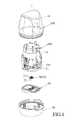
도 1 은 본 발명에 따른 삽입 장치의 제 1 실시예를 나타내는 분해 사시도이다.
도 2 는 제 1 실시예를 나타내는 부분적인 분해 사시도이다.
도 3 은 초기 상태에서 제 1 실시예를 나타내는 단면도이다.
도 4 는 도 3 에서 IV-IV 를 따라서 취해진 단면도이다.
도 5 는 제 1 실시예를 도시하는 저부 분해 사시도이다.
도 6 은 제 1 실시예의 하부 케이싱이 제거된 것을 나타내는 단면도이다.
도 7 은 도 6 에서 VII-VII 를 따라서 취해진 단면도이다.
도 8 은 제 1 실시예의 상부 케이싱이 눌려진 것을 나타내는 단면도이다.
도 9 는 도 8 에서 IX-IX 를 따라서 취해진 단면도이다.
도 10 은 삽입 위치에서 제 1 실시예의 삽입 시트를 나타내는 단면도이다.
도 11 은 도 10 에서 XI-XI 를 따라서 취해진 단면도이다.
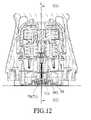
도 12 는 제 1 실시예의 수축 시트가 수축된 것을 나타내는 단면도이다.
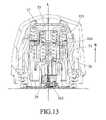
도 13 은 도 12 에서 XIII-XIII 를 따라서 취해진 단면도이다.
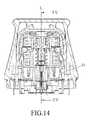
도 14 는 분리된 상태에서 제 1 실시예를 도시하는 단면도이다.
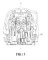
도 15 는 도 14 에서 XV-XV 를 따라서 취해진 단면도이다.
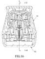
도 16 은 상부 케이싱에 다시 결합된 하부 케이싱을 나타내는 단면도이다.
도 17 은 도 16 에서 XVII-XVII 를 따라서 취해진 단면도이다.
도 18 은 제 1 실시예의 삽입 작용을 나타내는 개략도이다.
도 19 는 본 발명에 따른 삽입 장치의 제 2 실시예를 나타내는 단면도이다.
도 20 은 본 발명에 따른 삽입 장치의 제 3 실시예를 도시하는 단면도이다.Other features and advantages of the present invention will become apparent from the following detailed description of embodiments with reference to the accompanying drawings.
1 is an exploded perspective view showing a first embodiment of an insertion device according to the present invention.
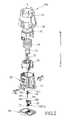
Fig. 2 is a partially exploded perspective view showing the first embodiment;
3 is a cross-sectional view showing the first embodiment in an initial state.
FIG. 4 is a cross-sectional view taken along IV-IV in FIG. 3 ;
Fig. 5 is a bottom exploded perspective view showing the first embodiment;
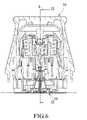
Fig. 6 is a cross-sectional view showing that the lower casing of the first embodiment is removed.
FIG. 7 is a cross-sectional view taken along VII-VII in FIG. 6 .
Fig. 8 is a cross-sectional view showing that the upper casing of the first embodiment is pressed.
Fig. 9 is a cross-sectional view taken along line IX-IX in Fig. 8;
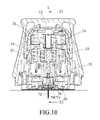
Fig. 10 is a sectional view showing the insertion sheet of the first embodiment in the insertion position;
FIG. 11 is a cross-sectional view taken along XI-XI in FIG. 10 ;
Fig. 12 is a cross-sectional view showing that the shrinkable sheet of the first embodiment is shrunk.
13 is a cross-sectional view taken along XIII-XIII in FIG. 12 ;
Fig. 14 is a cross-sectional view showing the first embodiment in a detached state;
15 is a cross-sectional view taken along XV-XV in FIG. 14 ;
16 is a cross-sectional view showing the lower casing coupled back to the upper casing;
17 is a cross-sectional view taken along XVII-XVII in FIG. 16 ;
Fig. 18 is a schematic diagram showing the insertion action of the first embodiment;
19 is a cross-sectional view showing a second embodiment of the insertion device according to the present invention.
Fig. 20 is a cross-sectional view showing a third embodiment of the insertion device according to the present invention;
본 발명이 상세하게 설명되기 전에, 적절한 것으로 간주될 경우에, 도면 번호 또는 도면 번호의 말미 부분들은 대응되거나 또는 유사한 요소들을 지시하도록 도면들 사이에서 반복될 것이며, 상기 요소들은 선택적으로는 유사한 특성들을 가질 수 있다.Before the present invention is described in detail, where deemed appropriate, a reference number or trailing portions of a reference number will be repeated among the drawings to indicate corresponding or similar elements, which elements optionally possessing similar characteristics. can have
도 1 내지 도 5 를 참조하면, 본 발명에 따른 삽입 장치의 제 1 실시예는 삽입 바늘을 호스트에 삽입하기 전에 삽입 바늘을 안정되게 움직이도록 안내할 수 있고, 제한 부재(100), 작동 유닛(200) 및 삽입 모듈(30)을 구비한다.1 to 5, the first embodiment of the insertion device according to the present invention can guide the insertion needle to move stably before inserting the insertion needle into the host, the limiting
제한 부재(100)는 상부 케이싱(10) 및, 상기 상부 케이싱(10)에 단단하게 결합될 수 있는 하부 케이싱(20)을 구비한다.The
작동 모듈(200)은 상부 케이싱(10)에 배치된 덮개 동체(12), 상기 덮개 동체(12) 안에 수용된 주 덮개(32), 상기 주 덮개(32)에 연결된 삽입 시트(33), 주 덮개(32) 및 삽입 시트(33)에 대하여 맞닿은 제 1 탄성 부재(34), 주 덮개(32)와 삽입 시트(33) 사이에 배치된 수축 시트(35) 및, 상기 수축 시트(35) 및 삽입 시트(33)에 대하여 맞닿은 제 2 탄성 부재(37)를 구비한다. 덮개 동체(12)는 한 쌍의 라이닝 맞물림 구조체(lining engaging structure, 124)를 그것의 저부 부분에 가진다. 제 1 탄성 부재(34) 및 제 2 탄성 부재(37)는 사전 압축된 스프링으로서 구성될 수 있다. 덮개 동체(12)는 그것의 내측의 둘러싸는 표면상에 한쌍의 강제 부분(urging portions, 123)을 가진다. 주 덮개(32)는 삽입 시트(33)를 향하여 연장되는 제한 부재(323)를 가진다. 삽입 시트(33)는 한쌍의 미늘 형상(barb-shaped) 수축 위치 선정 부분(334)들 및, 한쌍의 버클 부분(335)들을 가지며, 상기 버클 부분들은 덮개 동체(12)의 강제 부분(123)들에 의해 각각 밀릴 수 있다.The
삽입 모듈(30)은 삽입 바늘이 호스트로 삽입되기 전에 삽입 바늘을 안정되게 움직이도록 안내할 수 있고, 주 동체(31), 보조 삽입 시트(38), 삽입 바늘 조립체(36), 베이스(50) 및, 센서 조립체(70)를 구비한다.The
주 동체(31)는, 덮개 동체(12)의 라이닝 맞물림 구조체(124)와 각각 맞물릴 수 있는 한쌍의 동체 맞물림 구조체(311), 축방향 선(L)을 따라서 연장된 수용 구멍(312), 축방향 라인(L) 둘레에서 수용 구멍(312)상에 배치되고 수용 구멍(312)과 소통하는 복수개의 미끄럼 홈(313)들 및, 한 쌍의 정지 부분(314)을 가진다. 버클 부분(buckle portion, 335)들은 삽입 제한 구조체(A)를 형성하도록 주 동체(31)의 정지 부분(314)들에 대하여 각각 분리 가능하게 맞닿는다 (도 4 참조). 미끄럼 홈(313)들은 축방향 라인(L) 둘레에서 서로로부터 동등하게(equally) 이격된다. 이러한 실시예에서, 미끄럼 홈(313)들의 수는 3 개이다. 미끄럼 홈(313)들 각각은 삽입 방향(F)을 따라서 점진적으로 넓혀지는 벽 표면(315)을 가진다 (도 4). 미끄럼 홈(313)들의 각각의 벽 표면(315)은 0 도 내지 3 도 인 축방향 라인(L) 사이에 포함된 각도를 구비한다.The
보조 삽입 시트(38)는 베이스 부분(381), 상기 베이스 부분(381)에 연결된 복수개의 날개 부분(382)들 및, 베이스 부분(381)의 저부 표면으로부터 돌출된 복수개의 결합 부분(383)들을 가진다. 베이스 부분(381)은 수용 구멍(312)을 따라서 움직일 수 있다. 날개 부분(382)들 각각은 미끄럼 홈(313)들의 개별적인 하나를 따라서 움직일 수 있다. 날개 부분(382)들 각각은 미끄럼 홈(313)들의 개별적인 하나의 벽 표면(315)에 대하여 점 접촉(point contact)으로 탄성적으로 맞닿은 돌출 부분(385)을 가진다. 날개 부분(382)들 각각은 2 개의 노취(notches, 384)를 가지며, H 형상이다. 각각의 날개 부분(382)의 노취(384)들은 날개 부분(382)의 상부 부분 및 저부 부분에 각각 형성됨으로써, 축방향 라인(L)에 직각인 보조 삽입 시트(38)의 반경 방향으로 압축되기 전에, 각각의 날개 부분(382)은 복원력을 반경상 외측 방향으로 제공한다. 보조 삽입 시트(38)의 날개 부분(382)들은 축방향 라인(L) 둘레에서 서로로부터 동등하게 이격된다. 변형예에서, 날개 부분(382)의 수는 2 개일 수 있으며, 날개 부분(382)들은 서로로부터 180 도로 동등하게 이격된다.The
삽입 바늘 조립체(36)는, 수축 시트(35)와 보조 삽입 시트(38)의 베이스 부분(381) 사이에 장착된 바늘 시트(361) 및, 상기 바늘 시트(361)에 연결된 삽입 바늘(362)을 구비한다. 바늘 시트(361) 및 수축 시트(35)는 제조 공차에 기인한 그 사이의 오정렬(misalignment)을 방지하도록 서로로부터 분리될 수 있다. 도 18 을 참조하면, 호스트의 피부 표면과 삽입 바늘(362)의 팁 단부(tip end, 363) 사이의 거리는 초기 행정 거리(H)로서 정의된다. 이러한 실시예에서, 초기 행정 거리(H)는 1 밀리미터 보다 크지 않다.The
베이스(50)는 주 동체(31)의 저부 부분에 분리될 수 있게 위치되고, 접착 패드를 통해 피부 표면에 부착될 수 있다.The
센서 조립체(70)는 감지 시트(71) 및, 상기 감지 시트(71)내에 유지된 센서(72)를 구비한다. 감지 시트(71)는 복수개의 결합 요부(711)들을 가지며, 이것은 보조 삽입 시트(38)의 결합 돌출부(383)가 결합 요부들과 맞물릴 수 있게 한다. 삽입 바늘(362)은 감지 시트(71)를 통해 삽입되어 센서(72)를 덮는다.The
도 3 및 도 4 를 참조하면, 삽입 장치의 제 1 실시예가 조립된 이후에, 주 동체 조립체(300)의 상부 부분(302) 및 저부 부분(303)은 서로 연결되고, 덮개 동체(12)의 상부 부분 및 주 덮개(32)의 상부 부분은 서로로부터 거리(D)로 이격되고 (도 3), 삽입 시트(33)의 버클 부분(335)들은 주 동체(31)의 정지 부분(314)들에 대하여 각각 맞닿음으로써 사전 삽입 위치에 삽입 시트(33)를 위치시키고, 제 1 탄성 부재(34)는 복원력을 발생시키도록 주 덮개(32)와 삽입 시트(33) 사이에서 미리 압축되고, 제 2 탄성 부재(37)는 복원력을 발생시키도록 수축 시트(35)와 삽입 시트(33) 사이에서 미리 압축되고, 삽입 시트(33)의 수축 위치 선정 부분(retraction positioning portion, 334)은 주 덮개(32)의 제한 부재(323)에 의해 제한됨으로써 수축 시트(35)는 사전 삽입 위치에 있고, 보조 삽입 시트(38)의 결합 돌출부(383)들은 감지 시트(71)의 결합 요부(711)들에 맞춰짐으로써 감지 시트(71) 및 보조 삽입 시트(38)는 상호 연결되고, 보조 삽입 시트(38)는 삽입 바늘 조립체(36)의 바늘 시트(361)에 연결됨으로써 삽입 바늘 조립체(36)는 주 동체(31) 안에 유지되고 베이스(50)에 의해 차폐(shield)되며, 베이스(50)는 주 동체(31)에 대하여 위치된다. 삽입 시트(33)의 수축 위치 선정 부분(334)들은 주 덮개의 제한 부재(323)에 의해 제거 가능하게 제한됨으로써, 수축 시트(35)를 삽입 시트(33)에 대하여 상대적으로 위치시키는 수축 제한 구조체(B)를 형성한다 (도 4).3 and 4 , after the first embodiment of the insertion device is assembled, the upper part 302 and the bottom part 303 of the main body assembly 300 are connected to each other, and the The upper portion and the upper portion of the
도 6 및 도 7 을 참조하면, 베이스(50)는 호스트의 피부 표면의 삽입되어야 하는 부분에 우선 위치된다. 상부 케이싱(10)이 눌려지지 않을 때, 주 동체(31)의 정지 부분(314)들과 삽입 시트(33)의 버클 부분(335)들 사이에 형성된 삽입 제한 구조체(A)는 삽입 시트(33)를 사전 삽입 위치에 유지한다. 도 8 및 도 9 를 참조하면, 상부 케이싱(10)이 피부 표면을 향해 눌려질 때, 삽입 시트(33)의 버클 부분(335)들은 상부 케이싱(10)의 강제 부분(123)들에 의해 밀려져서 내측으로 변형되며 주 동체(31)의 정지 부분(314)들로부터 각각 분리됨으로써, 삽입 제한 구조체(A)가 접혀진다. 동시에, 주 동체(31)의 동체 맞물림 구조체(311)는 각각 덮개 동체(12)의 라이닝 맞물림 구조체(124)와 맞물림으로써, 상부 케이싱(10)은 주 동체(31)에 대하여 위치된다.Referring to FIGS. 6 and 7 , the
도 10 및 도 11 을 참조하면, 삽입 제한 구조체(A)가 접혀진 후에, 제 1 탄성 부재(34)의 복원력은 해제될 수 있고, 삽입 시트(33)를 삽입 위치로 움직여서 자동 삽입을 구현함으로써, 센서 조립체(70)는 삽입 시트(33)에 의하여 사후 삽입 위치로 움직이고, 센서(72)의 일부는 피부 표면 아래에 삽입되고, 감지 시트(71)는 베이스(50)의 장착 부분(500)상으로 위치된다. 센서(72)가 피부 표면 아래에 삽입된 이후에, 주 덮개(32)의 제한 부재(323)는 삽입 시트(33)의 수축 위치 선정 부분(334)들로부터 분리됨으로써, 수축 위치 선정 부분(334)들은 외측으로 변형될 수 있어서 수축 제한 구조체(B)를 접는다. 그에 의해, 제 2 탄성 부재(37)의 복원력은 방출될 수 있고, 수축 시트(35)를 구동하여 수축 방향(R)으로 삽입 시트(33)의 수축 위치 선정 부분(334)들을 지나서 피부 표면으로부터 멀어지게 움직여서, 삽입 바늘 조립체(36)는 보조 삽입 시트(38)로부터 분리되고 삽입 시트(33)로 수축되어 그것의 삽입 바늘(362)을 감추고 자동 수축을 구현한다 (도 12 및 도 13). 보조 삽입 시트(38)의 결합 돌출부(383)들은 감지 시트(71)의 결합 요부(711)들 안에 맞춰지게 유지됨으로써, 보조 삽입 시트(38)는 센서 조립체(70)의 감지 시트(71)에 연결된다. 센서 조립체(70)는 삽입 작용 동안에 베이스(50) 안에 위치되고, 베이스(50)는 그것의 접착 패드(52)에 의하여 피부 표면에 달라붙는다 (도 14 및 도 15 를 참조하면, 베이스(50)는 주 동체(31)의 저부 부분으로부터 분리되었다).10 and 11 , after the insertion limiting structure A is folded, the restoring force of the first
도 16 및 도 17 을 참조하면, 삽입 작용이 완료된 이후에, 분리된 하부 케이싱(20)은 상부 케이싱(10)에 다시 결합될 수 있어서, 사용된 삽입 장치는 의료 폐기물의 폐기물 기준에 부합되게 처리될 수 있다.16 and 17 , after the insertion operation is completed, the separated
도 3 내지 도 5 및 도 18 을 참조하면, 삽입하는 동안에, 삽입 바늘 조립체(36)의 초기 속도는 삽입 바늘(362)이 삽입 방향(F)에 평행한 것을 보장하기에 불충분하다. 이때, 미끄럼 홈(313)들의 벽 표면(315)들과 날개 부분(382)들의 돌출 부분(385)들 사이의 접촉은, 삽입 바늘(362)이 삽입 방향(F)에 평행하도록 삽입 바늘(362)을 위치시키는 역할을 한다. 삽입의 직선성을 제공하고 삽입 바늘(362)이 삽입 방향(F)에 대하여 경사지는 것을 방지하도록 삽입 바늘 조립체(36)가 가속된 후에, 날개 부분(382)들의 돌출 부분(385)들은 삽입 방향(F)을 따라서 점진적으로 넓혀지는 미끄럼 홈(313)들의 벽 표면(315)들의 부분들로부터 분리된다. 따라서, 삽입 바늘(362)은 초기 행정 거리(H)에서 안정되게 안내될 수 있고, 초기 행정 거리(H) 이후에 삽입 바늘(362)이 피부 표면에 접촉할 때 피부 표면에 의해 지지됨으로써, 피부 표면 아래에 흔들리지 않고(steadily) 그리고 신속하게 삽입된다. 각각의 날개 부분(382)의 노취(384)들에 의하여, 각각의 날개 부분(382)은 보조 삽입 시트(38)의 반경 방향에서 압축될 수 있고, 압축된 이후에 방사상 외측 방향으로 복원력을 발생시킨다. 더욱이, 날개 부분(382)들의 돌출 부분(385)들은 미끄럼 홈(313)들의 벽 표면(315)들에 대하여 맞닿아서 삽입 바늘 조립체(36)를 위치시킴으로써, 삽입 바늘(362)은 삽입 방향(F)에 대하여 경사지게 되는 것이 방지되고, 삽입 바늘(362)은 호스트에게 흔들리지 않고 삽입될 수 있어서 호스트의 불편을 감소시킨다.3-5 and 18 , during insertion, the initial velocity of the
도 19 를 참조하면, 본 발명에 따른 삽입 장치의 제 2 실시예는, 보조 삽입 시트(38')의 날개 부분(382')들 각각이 위로 개방된 노취(384')를 가진다는 점에서 제 1 실시예와 상이하다. 각각의 날개 부분(382')의 노취(384')는 날개 부분(382')의 상부 부분으로부터 아래로 만입됨으로서, 각각의 날개 부분(382')은 축방향 라인(L)에 직각인 보조 삽입 시트(38')의 반경 방향에서 압축될 수 있고, 압축된 후에 방사상 외측 방향으로 복원력을 발생시킨다.Referring to FIG. 19 , a second embodiment of an insertion device according to the present invention is a second embodiment in that each of the
도 20 을 참조하면, 본 발명에 따른 삽입 장치의 제 3 실시예는, 보조 삽입 시트(38”)의 날개 부분(382”)들 각각이 아래로 개방된 노취(384”)를 가진다는 점에서 제 1 실시예와 상이하다. 각각의 날개 부분(382”)의 노취(384”)는 날개 부분(382”)의 저부 부분으로부터 위로 만입됨으로써, 각각의 날개 부분(382”)은 축방향 라인(L)에 직각인 보조 삽입 시트(38”)의 반경 방향에서 압축될 수 있고, 압축된 이후에 방사상 외측 방향에서 복원력을 발생시킨다.Referring to FIG. 20 , a third embodiment of an insertion device according to the present invention is provided in that each of the
요약하면, 삽입 모듈(30)의 삽입 바늘 조립체(36)는 보조 삽입 시트(38)와 조립되고, 날개 부분(382)들의 돌출 부분(385)들과 미끄럼 홈(313)들의 벽 표면(315)들 사이에서의 접촉을 통해 위치됨으로써, 삽입 바늘(362)은 초기 행정 거리(H)에서 안정되게 안내될 수 있고, 삽입 방향(F)에 경사지는 것이 방지되어 호스트의 불편을 감소시킨다.In summary, the
상기 설명에서, 설명의 목적을 위하여, 실시예의 완전한 이해를 제공하도록 다수의 특정 세부 내용들이 기재되었다. 그러나, 이들 특정한 세부 내용 없이 하나 이상의 다른 실시예들이 구현될 수 있음은 당업자에게 명백할 것이다. 본 명세서를 통하여 "하나의 실시예", 실시예", 서수로 지시된 실시예등에 대한 참조는 특정의 특징, 구조 또는 성격이 본 발명의 실시예에 포함될 수 있음을 의미하는 것으로 이해되어야 한다. 또한 명세서에서 다양한 특징들은 다양한 본 발명의 양상들에 대한 이해를 돕고 발명을 설명할 목적으로 때때로 단일의 실시예, 도면 또는 설명에서 함께 그룹을 형성하고, 하나의 실시예로부터의 하나 이상의 특징들 또는 특정의 세부 내용들은, 적절한 경우에, 본 발명의 실시에 있어서 다른 실시예로부터의 하나 이상의 특징들 또는 특정의 세부 내용들과 함께 실시될 수 있다.In the foregoing description, for purposes of explanation, numerous specific details have been set forth in order to provide a thorough understanding of the embodiments. However, it will be apparent to one skilled in the art that one or more other embodiments may be implemented without these specific details. Reference throughout this specification to "one embodiment", an embodiment, an ordinal numbered embodiment, etc. should be understood to mean that a particular feature, structure, or nature may be included in the embodiment of the present invention. Also, various features in the specification are sometimes grouped together in a single embodiment, drawing or description, and one or more features from one embodiment or for purposes of explaining the invention and to aid understanding of various aspects of the invention Specific details, where appropriate, may be practiced in conjunction with specific details or one or more features from other embodiments in the practice of the present invention.
본 발명은 예시적인 실시예로 간주되는 것과 관련하여 설명되었지만, 본 발명은 개시된 실시예에 제한되지 않으며, 가장 넓은 해석의 사상 및 범위내에 포함되는 다양한 구성들을 포괄하도록 의도됨으로써 모든 그러한 변형 및 등가의 구성을 포괄한다는 점이 이해되어야 한다.While the present invention has been described in connection with what is considered to be an exemplary embodiment, the invention is not limited to the disclosed embodiment, but is intended to cover various configurations included within the spirit and scope of the broadest interpretation, so that all such modifications and equivalents It should be understood that it encompasses composition.
10. 상부 케이싱 12. 덮개 동체
32. 주 동체 33. 삽입 시트
100. 제한 부재 200. 작동 모듈10.
32.
100.
Claims (20)
Translated fromKorean축방향 라인을 따라서 연장된 수용 구멍 및, 상기 축방향 라인 둘레에 배치되고 상기 수용 구멍(accommodating hole)과 소통하는 복수개의 미끄럼 홈들을 가진, 주 동체;
베이스 부분 및, 상기 베이스 부분에 연결된 복수개의 날개 부분들을 가진 보조 삽입 시트(auxiliary insertion seat)로서, 상기 날개 부분들 각각은 상기 미끄럼 홈들 중 개별의 하나를 따라서 움직일 수 있고, 돌출 부분을 가지는, 보조 삽입 시트;
상기 보조 삽입 시트의 상기 베이스 부분과 조립되는 바늘 시트(needle seat) 및, 상기 바늘 시트에 연결된 삽입 바늘(insertion needle)을 구비한 삽입 바늘 조립체로서, 상기 삽입 바늘의 팁 단부(tip end)와 호스트의 피부 표면 사이의 거리는 초기 행정 거리 (initial stroke distance)로서 형성되는, 삽입 바늘 조립체; 및,
감지 시트(sensing seat) 및, 상기 감지 시트에 의해 유지된 센서를 구비하는 센서 조립체로서, 상기 감지 시트는 상기 보조 삽입 시트의 상기 베이스 부분과 조립되고, 상기 삽입 바늘은 상기 감지 시트를 통해 삽입되어 상기 센서를 덮는, 센서 조립체;를 포함하고,
상기 미끄럼 홈들 각각은 벽 표면을 가지고, 상기 날개 부분들 각각의 상기 돌출 부분은 상기 미끄럼 홈들의 개별적인 하나의 상기 벽 표면에 대하여 점 접촉으로 맞닿음으로써, 상기 보조 삽입 시트는 상기 돌출 부분들과 상기 벽 표면들 사이의 간섭을 통하여 호스트로 삽입되기 전에 고정되어 안정된 삽입을 제공하고 상기 삽입 바늘이 상기 초기 행정 거리에서 경사지는 것을 방지하는, 삽입 모듈.An insertion module configured to stably move an insertion needle before being inserted into a host, the insertion module comprising:
a main body having an accommodating hole extending along the axial line and a plurality of sliding grooves disposed around the axial line and communicating with the accommodating hole;
an auxiliary insertion seat having a base portion and a plurality of wing portions connected to the base portion, each of the wing portions being movable along a respective one of the sliding grooves and having a projecting portion insert sheet;
an insertion needle assembly having a needle seat assembled with the base portion of the auxiliary insertion sheet, and an insertion needle connected to the needle seat, wherein a tip end of the insertion needle and a host The distance between the skin surfaces of the insertion needle assembly is formed as the initial stroke distance; and,
A sensor assembly comprising a sensing seat and a sensor held by the sensing seat, wherein the sensing seat is assembled with the base portion of the auxiliary insertion sheet, and the insertion needle is inserted through the sensing sheet a sensor assembly covering the sensor; and
Each of the sliding grooves has a wall surface, and the protruding portion of each of the wing portions abuts in point contact against the wall surface of a respective one of the sliding grooves, whereby the auxiliary insert sheet is connected to the projecting portions and the An insertion module secured prior to insertion into a host through interference between wall surfaces to provide a stable insertion and to prevent the insertion needle from tilting in the initial stroke.
삽입 모듈(insertion module);을 포함하는 삽입 장치로서,
상기 삽입 모듈은:
축방향 라인을 따라서 연장된 수용 구멍 및, 축방향 라인 둘레에 배치되고 상기 수용 구멍과 소통하는 복수개의 미끄럼 홈들을 가진 주 동체;
베이스 부분 및, 상기 베이스 부분에 연결된 복수개의 날개 부분들을 가진 보조 삽입 시트로서, 상기 날개 부분들 각각은 상기 미끄럼 홈들의 개별적인 하나 안에서 왕복하고, 돌출 부분을 가지는, 보조 삽입 시트;
상기 보조 삽입 시트의 상기 베이스 부분과 조립된 바늘 시트(needle seat) 및, 상기 바늘 시트에 연결된 삽입 바늘을 구비하는 삽입 바늘 조립체로서, 상기 삽입 바늘의 팁 단부(tip end)와 호스트의 피부 표면 사이의 거리는 초기 행정 거리(initial stroke distance)로서 형성되는, 삽입 바늘 조립체; 및,
감지 시트(sensing seat) 및, 상기 감지 시트 안에 유지된 센서를 구비하는 센서 조립체로서, 상기 감지 시트는 상기 보조 삽입 시트의 상기 베이스 부분과 조립되고, 상기 삽입 바늘은 상기 감지 시트를 통해 삽입되어 상기 센서를 덮는, 센서 조립체;를 구비하고,
상기 미끄럼 홈들 각각은 벽 표면을 가지고, 상기 날개 부분들 각각의 상기 돌출 부분은 상기 미끄럼 홈들의 개별적인 하나의 상기 벽 표면에 대하여 점 접촉(point contact)에 의해 탄성적으로 맞닿음으로써, 상기 보조 삽입 시트는 상기 돌출 부분들과 상기 벽 표면들 사이의 간섭을 통해 호스트로 삽입되기 전에 고정되어 안정된 삽입을 제공하고 상기 삽입 바늘이 상기 초기 행정 거리에서 경사지는 것을 방지하는, 삽입 장치.a cover body, a main cover disposed within the cover body, an insert sheet connected to the main cover, a first elastic member abutting against the main cover and the insert seat, a retraction sheet disposed between the main cover and the insert seat seat) and a second elastic member abutting against the retractable seat and the inserting seat, an actuation module; and,
As an insertion device comprising a; insertion module (insertion module),
The insert module is:
a main body having a receiving hole extending along the axial line and a plurality of sliding grooves disposed around the axial line and communicating with the receiving hole;
an auxiliary insert sheet having a base portion and a plurality of wing portions connected to the base portion, each of the wing portions reciprocating within a respective one of the sliding grooves and having a protruding portion;
an insertion needle assembly comprising a needle seat assembled with the base portion of the auxiliary insertion sheet, and an insertion needle connected to the needle seat, between a tip end of the insertion needle and a skin surface of a host the insertion needle assembly, defined as the initial stroke distance; and,
A sensor assembly having a sensing seat and a sensor held in the sensing seat, wherein the sensing seat is assembled with the base portion of the auxiliary insertion sheet, and the insertion needle is inserted through the sensing sheet to make the a sensor assembly covering the sensor; and
Each of the sliding grooves has a wall surface, and the protruding portion of each of the wing portions elastically abuts by point contact against the wall surface of a respective one of the sliding grooves, whereby the auxiliary insertion wherein the seat is secured prior to insertion into the host through interference between the protruding portions and the wall surfaces to provide a stable insertion and to prevent the insertion needle from tilting in the initial stroke.
12. The insertion device of claim 11, wherein the initial stroke is less than 1 millimeter.
Applications Claiming Priority (2)
| Application Number | Priority Date | Filing Date | Title |
|---|---|---|---|
| US201962882140P | 2019-08-02 | 2019-08-02 | |
| US62/882,140 | 2019-08-02 |
Publications (2)
| Publication Number | Publication Date |
|---|---|
| KR20210016312A KR20210016312A (en) | 2021-02-15 |
| KR102449247B1true KR102449247B1 (en) | 2022-09-29 |
Family
ID=71899622
Family Applications (2)
| Application Number | Title | Priority Date | Filing Date |
|---|---|---|---|
| KR1020200097023AActiveKR102449247B1 (en) | 2019-08-02 | 2020-08-03 | Insertion Module and Insertion Device Having Insertion Module |
| KR1020200097057AActiveKR102509849B1 (en) | 2019-08-02 | 2020-08-03 | Physiological Signal Monitoring Device And Sensor Holder Thereof |
Family Applications After (1)
| Application Number | Title | Priority Date | Filing Date |
|---|---|---|---|
| KR1020200097057AActiveKR102509849B1 (en) | 2019-08-02 | 2020-08-03 | Physiological Signal Monitoring Device And Sensor Holder Thereof |
Country Status (10)
| Country | Link |
|---|---|
| US (7) | US11504032B2 (en) |
| EP (7) | EP3771409B1 (en) |
| JP (3) | JP6986603B2 (en) |
| KR (2) | KR102449247B1 (en) |
| CN (22) | CN112294301B (en) |
| AU (2) | AU2020294300B2 (en) |
| CA (2) | CA3104329A1 (en) |
| DE (1) | DE202020104460U1 (en) |
| TW (26) | TWI723733B (en) |
| WO (2) | WO2021023148A1 (en) |
Families Citing this family (37)
| Publication number | Priority date | Publication date | Assignee | Title |
|---|---|---|---|---|
| US9788771B2 (en) | 2006-10-23 | 2017-10-17 | Abbott Diabetes Care Inc. | Variable speed sensor insertion devices and methods of use |
| US11071478B2 (en) | 2017-01-23 | 2021-07-27 | Abbott Diabetes Care Inc. | Systems, devices and methods for analyte sensor insertion |
| CN112423664B (en) | 2018-06-07 | 2025-01-21 | 雅培糖尿病护理公司 | Focused sterilization and sterilized sub-assemblies for analyte monitoring systems |
| CA3230184A1 (en)* | 2019-08-02 | 2021-02-02 | Bionime Corporation | Physiological signal monitoring device |
| CN112294301B (en)* | 2019-08-02 | 2024-12-31 | 华广生技股份有限公司 | Physiological signal sensor device |
| EP4017357A4 (en)* | 2019-08-19 | 2023-04-19 | Medtrum Technologies Inc. | MEASURING DEVICE |
| CA3188510A1 (en) | 2020-08-31 | 2022-03-03 | Vivek S. RAO | Systems, devices, and methods for analyte sensor insertion |
| AU2021344214A1 (en)* | 2020-09-15 | 2023-03-23 | Abbott Diabetes Care Inc. | Systems, devices, and methods for analyte monitoring |
| US11852643B2 (en)* | 2020-10-13 | 2023-12-26 | Bionime Corporation | Physiological signal monitoring device |
| TWI793800B (en)* | 2020-10-14 | 2023-02-21 | 華廣生技股份有限公司 | Insertion needle structure and inserter |
| TWI849296B (en)* | 2021-01-08 | 2024-07-21 | 華廣生技股份有限公司 | Patch and method for using a patch |
| EP4346587A4 (en)* | 2021-05-31 | 2024-10-30 | Medtrum Technologies Inc. | ANALYTE DETECTION DEVICE INTEGRATED INTO A BATTERY ENCLOSURE |
| CN113499127B (en)* | 2021-06-28 | 2024-03-01 | 苏州百孝医疗科技有限公司 | Fixing structure of sensor base and method for removing sensor base |
| KR102592776B1 (en)* | 2021-06-29 | 2023-10-25 | 주식회사 아이센스 | Needle for transcutaneous sensor insertion and needle assembly having the same |
| CN115704820B (en)* | 2021-08-06 | 2025-08-05 | 上海移宇科技股份有限公司 | Body fluid analyte detection devices |
| CN115868974B (en)* | 2021-09-29 | 2025-09-09 | 上海微创生命科技有限公司 | Medical equipment and medical auxiliary device |
| CN116172549B (en)* | 2021-11-26 | 2025-08-12 | 上海微创生命科技有限公司 | medical devices |
| CN116195994A (en)* | 2021-11-30 | 2023-06-02 | 上海微创生命科技有限公司 | Sterilization box assembly, implanter and implantation system |
| CN114642426A (en)* | 2022-03-02 | 2022-06-21 | 苏州百孝医疗科技有限公司 | Method for manufacturing electronic device and electronic device |
| CN114831633B (en)* | 2022-04-29 | 2025-07-25 | 天津九安医疗电子股份有限公司 | Sensor implantation device |
| CN115089274A (en)* | 2022-05-26 | 2022-09-23 | 浙江康德莱医疗器械股份有限公司 | A puncture guide needle |
| WO2024028507A1 (en)* | 2022-08-05 | 2024-02-08 | Unomedical A/S | Inserter assembly and method |
| WO2024028506A1 (en)* | 2022-08-05 | 2024-02-08 | Unomedical A/S | Anchor assembly |
| TWD226583S (en)* | 2022-08-31 | 2023-07-21 | 華廣生技股份有限公司 | Physiological signal monitoring patch |
| TWD226584S (en)* | 2022-08-31 | 2023-07-21 | 華廣生技股份有限公司 | Physiological signal monitoring patch |
| TWD226582S (en)* | 2022-08-31 | 2023-07-21 | 華廣生技股份有限公司 | Physiological signal monitoring patch |
| TWI806771B (en)* | 2022-09-16 | 2023-06-21 | 英業達股份有限公司 | Anti-static electricity type electronic device |
| CN116058937A (en)* | 2022-10-11 | 2023-05-05 | 深圳可孚生物科技有限公司 | A biosensor-assisted implantation device |
| WO2024080457A1 (en)* | 2022-10-14 | 2024-04-18 | 국민대학교산학협력단 | Scalable implantable biosensor device |
| CN115399757B (en)* | 2022-10-31 | 2023-01-24 | 深圳刷新生物传感科技有限公司 | High-reliability implantation device of implantable biosensor |
| USD1095842S1 (en)* | 2023-02-10 | 2025-09-30 | I-Sens, Inc. | Continuous blood glucose measurement sensor |
| US20240298929A1 (en)* | 2023-03-08 | 2024-09-12 | Medtronic Minimed, Inc. | Substrate sealing configurations and methods |
| TWD231831S (en)* | 2023-03-15 | 2024-06-21 | 華廣生技股份有限公司 臺中市南區大慶街2段100號 (中華民國) | Part of a splitter for a physiological monitoring device |
| CN116626132A (en)* | 2023-05-15 | 2023-08-22 | 广州达安基因股份有限公司 | Implantable biosensor and preparation method thereof |
| CN116548963B (en)* | 2023-07-07 | 2023-09-05 | 苏州百孝医疗科技有限公司 | Percutaneous analyte continuous detection system and method of installing same |
| EP4534008A1 (en)* | 2023-08-21 | 2025-04-09 | Shanghai United Imaging Microelectronics Technology Co., Ltd. | Analyte sensor |
| WO2025162779A1 (en)* | 2024-01-31 | 2025-08-07 | Roche Diabetes Care Gmbh | Continuous analyte monitoring device |
Citations (1)
| Publication number | Priority date | Publication date | Assignee | Title |
|---|---|---|---|---|
| CN107949314A (en) | 2015-12-30 | 2018-04-20 | 德克斯康公司 | Transdermal Analyte Sensor Systems and Methods |
Family Cites Families (255)
| Publication number | Priority date | Publication date | Assignee | Title |
|---|---|---|---|---|
| US3102539A (en)* | 1960-11-23 | 1963-09-03 | Graham Chemical Corp | Disposable cartridge type hypodermic syringe devices |
| EP0221005A3 (en)* | 1985-09-07 | 1987-12-02 | Wagner, Wolfgang, Dr.med. | Injection device with sensor |
| US5165407A (en)* | 1990-04-19 | 1992-11-24 | The University Of Kansas | Implantable glucose sensor |
| US5299571A (en)* | 1993-01-22 | 1994-04-05 | Eli Lilly And Company | Apparatus and method for implantation of sensors |
| JP2947064B2 (en)* | 1994-05-18 | 1999-09-13 | 住友電装株式会社 | connector |
| CN1174713C (en)* | 1995-08-29 | 2004-11-10 | 光谱股份有限公司 | Microporation method of human skin for drug delivery and monitoring applications |
| US6013058A (en)* | 1996-06-12 | 2000-01-11 | Biolink Corporation | Device for subcutaneous accessibility |
| US7899511B2 (en)* | 2004-07-13 | 2011-03-01 | Dexcom, Inc. | Low oxygen in vivo analyte sensor |
| US7657297B2 (en)* | 2004-05-03 | 2010-02-02 | Dexcom, Inc. | Implantable analyte sensor |
| JPH10253654A (en)* | 1997-03-11 | 1998-09-25 | Fujitsu Ten Ltd | Acceleration sensor packaging structure |
| KR20010013962A (en)* | 1997-06-20 | 2001-02-26 | 에프.지.엠. 헤르만스 ; 이.에이치. 리링크 | Preloaded implantation device |
| US6516808B2 (en)* | 1997-09-12 | 2003-02-11 | Alfred E. Mann Foundation For Scientific Research | Hermetic feedthrough for an implantable device |
| US5967986A (en)* | 1997-11-25 | 1999-10-19 | Vascusense, Inc. | Endoluminal implant with fluid flow sensing capability |
| US8465425B2 (en)* | 1998-04-30 | 2013-06-18 | Abbott Diabetes Care Inc. | Analyte monitoring device and methods of use |
| US8346337B2 (en)* | 1998-04-30 | 2013-01-01 | Abbott Diabetes Care Inc. | Analyte monitoring device and methods of use |
| GB2337118A (en)* | 1998-05-06 | 1999-11-10 | Csi Technology Inc | Interchangeable sensor monitoring device |
| AU1889001A (en)* | 1999-12-13 | 2001-06-18 | Arkray, Inc. | Body fluid measuring apparatus with lancet and lancet holder used for the measuring apparatus |
| US7393344B2 (en)* | 1999-12-23 | 2008-07-01 | Owais Mohammed | Hypodermic syringe needle assembly and method of making the same |
| DE60015721T2 (en)* | 2000-03-21 | 2005-03-31 | Radi Medical Systems Ab | Passive biotelemetry |
| JP4700209B2 (en)* | 2000-03-21 | 2011-06-15 | ラディ・メディカル・システムズ・アクチェボラーグ | Passive biotelemetry |
| US7006858B2 (en)* | 2000-05-15 | 2006-02-28 | Silver James H | Implantable, retrievable sensors and immunosensors |
| US7181261B2 (en)* | 2000-05-15 | 2007-02-20 | Silver James H | Implantable, retrievable, thrombus minimizing sensors |
| US6589229B1 (en)* | 2000-07-31 | 2003-07-08 | Becton, Dickinson And Company | Wearable, self-contained drug infusion device |
| US8454552B2 (en)* | 2000-08-24 | 2013-06-04 | Cardiac Science Corporation | Method for constructing an instrument with a covered bore for subcutaneous implantation |
| US8348882B2 (en)* | 2000-08-24 | 2013-01-08 | Cardiac Science Corporation | Instrument with a covered bore for subcutaneous implantation |
| US7736330B2 (en)* | 2000-08-24 | 2010-06-15 | Bardy Gust H | Subcutaneous implantation instrument with dissecting tool and method of construction |
| GB0025147D0 (en)* | 2000-10-13 | 2000-11-29 | Torsana Diabetes Diagnostics A | Optical sensor for in situ measurement of analytes |
| US6560471B1 (en)* | 2001-01-02 | 2003-05-06 | Therasense, Inc. | Analyte monitoring device and methods of use |
| EP1381408A4 (en) | 2001-02-22 | 2007-06-13 | Insulet Corp | Modular infusion device and method |
| WO2003088851A1 (en)* | 2001-06-12 | 2003-10-30 | Pelikan Technologies, Inc. | Tissue penetration device |
| GB0116853D0 (en)* | 2001-07-10 | 2001-09-05 | Torsana Diabetes Diagnostics A | Optical sensor containing particles for in SITU measurement of analytes |
| US7025760B2 (en)* | 2001-09-07 | 2006-04-11 | Medtronic Minimed, Inc. | Method and system for non-vascular sensor implantation |
| US8506550B2 (en)* | 2001-09-07 | 2013-08-13 | Medtronic Minimed, Inc. | Method and system for non-vascular sensor implantation |
| WO2003034902A2 (en)* | 2001-10-23 | 2003-05-01 | Medtronic Minimed Inc. | Method and system for non-vascular sensor implantation |
| US9492111B2 (en)* | 2002-04-22 | 2016-11-15 | Medtronic Minimed, Inc. | Methods and materials for stabilizing analyte sensors |
| US7020508B2 (en)* | 2002-08-22 | 2006-03-28 | Bodymedia, Inc. | Apparatus for detecting human physiological and contextual information |
| US7070591B2 (en)* | 2002-09-17 | 2006-07-04 | Transoma Medical, Inc. | Vascular access port with physiological sensor |
| US7736309B2 (en)* | 2002-09-27 | 2010-06-15 | Medtronic Minimed, Inc. | Implantable sensor method and system |
| US7381184B2 (en)* | 2002-11-05 | 2008-06-03 | Abbott Diabetes Care Inc. | Sensor inserter assembly |
| CN2585624Y (en)* | 2002-12-03 | 2003-11-12 | 名世电子企业股份有限公司 | pulse meter transmitter |
| US20070208245A1 (en)* | 2003-08-01 | 2007-09-06 | Brauker James H | Transcutaneous analyte sensor |
| US7519408B2 (en)* | 2003-11-19 | 2009-04-14 | Dexcom, Inc. | Integrated receiver for continuous analyte sensor |
| US7699807B2 (en)* | 2003-11-10 | 2010-04-20 | Smiths Medical Asd, Inc. | Device and method for insertion of a cannula of an infusion device |
| US7309326B2 (en)* | 2003-11-18 | 2007-12-18 | Icu Medical, Inc. | Infusion set |
| WO2005092177A1 (en)* | 2004-03-22 | 2005-10-06 | Bodymedia, Inc. | Non-invasive temperature monitoring device |
| US20070135697A1 (en)* | 2004-04-19 | 2007-06-14 | Therasense, Inc. | Method and apparatus for providing sensor guard for data monitoring and detection systems |
| US8792955B2 (en)* | 2004-05-03 | 2014-07-29 | Dexcom, Inc. | Transcutaneous analyte sensor |
| US8452368B2 (en)* | 2004-07-13 | 2013-05-28 | Dexcom, Inc. | Transcutaneous analyte sensor |
| JP4870075B2 (en)* | 2004-07-13 | 2012-02-08 | デックスコム・インコーポレーテッド | Transcutaneous analyte sensor |
| US8565848B2 (en)* | 2004-07-13 | 2013-10-22 | Dexcom, Inc. | Transcutaneous analyte sensor |
| US7783333B2 (en)* | 2004-07-13 | 2010-08-24 | Dexcom, Inc. | Transcutaneous medical device with variable stiffness |
| US7654956B2 (en)* | 2004-07-13 | 2010-02-02 | Dexcom, Inc. | Transcutaneous analyte sensor |
| TWM269870U (en)* | 2004-10-01 | 2005-07-11 | Taiject Medical Device Co Ltd | Easy assembling and operating blood collector |
| US9788771B2 (en)* | 2006-10-23 | 2017-10-17 | Abbott Diabetes Care Inc. | Variable speed sensor insertion devices and methods of use |
| CN101107025A (en)* | 2005-01-17 | 2008-01-16 | 诺和诺德公司 | Fluid delivery device with integrated monitoring of physiological characteristics |
| US7285846B1 (en)* | 2005-02-22 | 2007-10-23 | Littelfuse, Inc. | Integrated circuit package with ESD protection |
| JP2006334155A (en)* | 2005-06-02 | 2006-12-14 | Terumo Corp | Blood component measuring apparatus and chip for measuring blood component |
| WO2007003431A1 (en)* | 2005-07-06 | 2007-01-11 | Medizinische Universität Graz | Device for and method of delivery and removal of substances in and from a tissue or vessel |
| US9072476B2 (en)* | 2005-09-23 | 2015-07-07 | Medtronic Minimed, Inc. | Flexible sensor apparatus |
| US8123705B2 (en)* | 2005-10-06 | 2012-02-28 | Boston Scientific Scimed, Inc. | Adjustable profile probe |
| US20070173706A1 (en)* | 2005-11-11 | 2007-07-26 | Isense Corporation | Method and apparatus for insertion of a sensor |
| US9615851B2 (en)* | 2005-11-11 | 2017-04-11 | Waveform Technologies, Inc. | Method and apparatus for insertion of a sensor |
| US9757061B2 (en)* | 2006-01-17 | 2017-09-12 | Dexcom, Inc. | Low oxygen in vivo analyte sensor |
| JP4802737B2 (en)* | 2006-01-31 | 2011-10-26 | パナソニック株式会社 | Chemical solution administration device and control method thereof |
| EP3165247B1 (en)* | 2006-02-09 | 2020-10-28 | DEKA Products Limited Partnership | Pumping fluid delivery systems and methods using force application assembley |
| ES2871822T3 (en)* | 2006-02-22 | 2021-11-02 | Dexcom Inc | Analyte sensor |
| US20090131778A1 (en)* | 2006-03-28 | 2009-05-21 | Jina Arvind N | Devices, systems, methods and tools for continuous glucose monitoring |
| US20090012372A1 (en)* | 2006-06-12 | 2009-01-08 | Novalert, Inc. | External sensing for implant rupture |
| US8583224B2 (en)* | 2006-09-08 | 2013-11-12 | Cardiac Pacemakers, Inc. | Implantable medical device and methods for automated detection of infection |
| EP2079358B1 (en)* | 2006-09-27 | 2011-08-10 | University of Connecticut | Implantable biosensor and methods of use thereof |
| US20080091089A1 (en)* | 2006-10-12 | 2008-04-17 | Kenneth Shane Guillory | Single use, self-contained surface physiological monitor |
| US8214007B2 (en)* | 2006-11-01 | 2012-07-03 | Welch Allyn, Inc. | Body worn physiological sensor device having a disposable electrode module |
| TWM314590U (en)* | 2006-12-11 | 2007-07-01 | Health & Life Co Ltd | Physical detector having water-proof structure |
| WO2008105768A1 (en)* | 2007-03-01 | 2008-09-04 | Dexcom, Inc. | Analyte sensor |
| EP1972267A1 (en)* | 2007-03-20 | 2008-09-24 | Roche Diagnostics GmbH | System for in vivo measurement of an analyte concentration |
| JP5429586B2 (en)* | 2007-03-30 | 2014-02-26 | 株式会社タニタ | Blood glucose state estimation method and apparatus |
| CA2680841A1 (en)* | 2007-04-04 | 2008-10-16 | Isense Corporation | Analyte sensing device having one or more sensing electrodes |
| US20130144144A1 (en)* | 2007-04-19 | 2013-06-06 | C.G.M.3 Ltd. | Device system and method for monitoring and controlling blood analyte levels |
| JP5546243B2 (en)* | 2007-07-18 | 2014-07-09 | パナソニックヘルスケア株式会社 | Blood test equipment |
| JP2009028062A (en)* | 2007-07-24 | 2009-02-12 | Sumitomo Electric Ind Ltd | Blood collector for biosensor and sensor chip measuring device |
| US20090043183A1 (en)* | 2007-08-08 | 2009-02-12 | Lifescan, Inc. | Integrated stent and blood analyte monitoring system |
| GB0716427D0 (en)* | 2007-08-23 | 2007-10-03 | Smartsensor Telemed Ltd | Glucose tolerance test device |
| US20090105634A1 (en)* | 2007-10-17 | 2009-04-23 | Alza Corporation | Anodic Reservoir for Electrotransport of Cationic Drug |
| AU2009219678A1 (en)* | 2008-02-27 | 2009-09-03 | Mon4D Ltd. | Device, system and method for modular analyte monitoring |
| ITTO20080143A1 (en)* | 2008-02-28 | 2009-08-29 | Amc Instruments S R L | DEVICE FOR MONITORING MULTIFUNE SYSTEMS |
| US9295786B2 (en)* | 2008-05-28 | 2016-03-29 | Medtronic Minimed, Inc. | Needle protective device for subcutaneous sensors |
| TWI354548B (en)* | 2008-07-18 | 2011-12-21 | Bionime Corp | Adjustable assembly of lancet device |
| ES2530450T3 (en)* | 2008-10-02 | 2015-03-03 | Eyesense Ag | Implantable sensor element |
| TWI503101B (en)* | 2008-12-15 | 2015-10-11 | Proteus Digital Health Inc | Body-associated receiver and method |
| US9402544B2 (en)* | 2009-02-03 | 2016-08-02 | Abbott Diabetes Care Inc. | Analyte sensor and apparatus for insertion of the sensor |
| US20100256524A1 (en)* | 2009-03-02 | 2010-10-07 | Seventh Sense Biosystems, Inc. | Techniques and devices associated with blood sampling |
| TWI413770B (en)* | 2009-04-24 | 2013-11-01 | Univ Nat Taiwan | Wireless biomedical monitoring system |
| EP2266458A1 (en)* | 2009-06-23 | 2010-12-29 | Roche Diagnostics GmbH | Sensor for in-vivo measurements |
| US8996089B2 (en)* | 2009-06-30 | 2015-03-31 | Arkray, Inc. | Continuous analysis device and sample component control system |
| DK3689237T3 (en)* | 2009-07-23 | 2021-08-16 | Abbott Diabetes Care Inc | Method of preparation and system for continuous analyte measurement |
| KR20120047896A (en)* | 2009-08-07 | 2012-05-14 | 우노메디컬 에이/에스 | Delivery device with sensor and one or more cannulas |
| TWI481383B (en)* | 2009-09-25 | 2015-04-21 | Univ Nat Chiao Tung | Biosensor and electrode structure thereof |
| EP2482724A2 (en) | 2009-09-30 | 2012-08-08 | Dexcom, Inc. | Transcutaneous analyte sensor |
| WO2011053788A2 (en)* | 2009-10-30 | 2011-05-05 | Seventh Sense Biosystems, Inc. | Relatively small devices applied to the skin, modular systems, and methods of use thereof |
| US10918298B2 (en)* | 2009-12-16 | 2021-02-16 | The Board Of Trustees Of The University Of Illinois | High-speed, high-resolution electrophysiology in-vivo using conformal electronics |
| EP2335565A1 (en)* | 2009-12-18 | 2011-06-22 | Roche Diagnostics GmbH | Protective container for holding reusable diagnostic components |
| WO2011088211A2 (en)* | 2010-01-13 | 2011-07-21 | Seventh Sense Biosystems, Inc. | Sampling device interfaces |
| WO2011112931A1 (en)* | 2010-03-12 | 2011-09-15 | The Board Of Trustees Of The University Of Illinois | Waterproof stretchable optoelectronics |
| US10448872B2 (en)* | 2010-03-16 | 2019-10-22 | Medtronic Minimed, Inc. | Analyte sensor apparatuses having improved electrode configurations and methods for making and using them |
| AU2011230596A1 (en)* | 2010-03-24 | 2012-01-19 | Abbott Diabetes Care Inc. | Medical device inserters and processes of inserting and using medical devices |
| LT3622883T (en)* | 2010-03-24 | 2021-08-25 | Abbott Diabetes Care, Inc. | Medical device inserters and processes of inserting and using medical devices |
| JP2011204483A (en)* | 2010-03-25 | 2011-10-13 | Denso Corp | Electrical connector and circuit board mounted with the same |
| KR20130018783A (en)* | 2010-03-30 | 2013-02-25 | 우노메디컬 에이/에스 | Medical device |
| JP2012026910A (en)* | 2010-07-26 | 2012-02-09 | Arkray Inc | Biosensor unit and biosensor system |
| TWI439689B (en)* | 2010-09-23 | 2014-06-01 | Bionime Corp | Electrochemical test specimen |
| DK2621339T3 (en)* | 2010-09-29 | 2020-02-24 | Dexcom Inc | ADVANCED SYSTEM FOR CONTINUOUS ANALYTICAL MONITORING |
| WO2012068393A1 (en)* | 2010-11-18 | 2012-05-24 | Abbott Diabetes Care Inc. | Adaptor for on-body analyte monitoring system |
| CN107961016B (en)* | 2010-12-09 | 2021-06-15 | 雅培糖尿病护理股份有限公司 | Analyte sensor having a sensing surface comprising a small sensing spot |
| WO2012097879A1 (en)* | 2011-01-21 | 2012-07-26 | St. Jude Medical Ab | Implantable device with improved surface characteristics |
| US8424388B2 (en)* | 2011-01-28 | 2013-04-23 | Medtronic, Inc. | Implantable capacitive pressure sensor apparatus and methods regarding same |
| CN102613978B (en)* | 2011-01-31 | 2014-12-03 | 厚美德生物科技股份有限公司 | Test strip |
| US9649113B2 (en)* | 2011-04-27 | 2017-05-16 | Covidien Lp | Device for monitoring physiological parameters in vivo |
| TWI569773B (en)* | 2011-05-26 | 2017-02-11 | 華廣生技股份有限公司 | System and method of measuring a physiological parameter therein |
| EP2720610B1 (en) | 2011-06-17 | 2025-07-16 | Abbott Diabetes Care Inc. | Stacked analyte sensor having a first electrode narrower than a second electrode of the sensor |
| US10638955B2 (en)* | 2011-06-30 | 2020-05-05 | Endotronix, Inc. | Pressure sensing implant |
| KR20140082642A (en)* | 2011-07-26 | 2014-07-02 | 글리젠스 인코포레이티드 | Tissue implantable sensor with hermetically sealed housing |
| JP6090795B2 (en)* | 2011-09-09 | 2017-03-08 | テルモ株式会社 | Sensor insertion device |
| WO2013038691A1 (en)* | 2011-09-14 | 2013-03-21 | パナソニック株式会社 | Biological information detection sensor supply device |
| TWI452997B (en)* | 2011-10-05 | 2014-09-21 | Univ Kun Shan | Biosensor chip with nano-structures |
| EP2586479A1 (en)* | 2011-10-31 | 2013-05-01 | Sanofi-Aventis Deutschland GmbH | Safety needle assembly |
| EP2713879B1 (en)* | 2011-12-11 | 2017-07-26 | Abbott Diabetes Care, Inc. | Analyte sensor devices, connections, and methods |
| WO2013105508A1 (en)* | 2012-01-13 | 2013-07-18 | パナソニック株式会社 | Biological information measurement apparatus |
| TWI477256B (en)* | 2012-01-19 | 2015-03-21 | Bionime Corp | Lancing device |
| US9931065B2 (en)* | 2012-04-04 | 2018-04-03 | Dexcom, Inc. | Transcutaneous analyte sensors, applicators therefor, and associated methods |
| US9883834B2 (en)* | 2012-04-16 | 2018-02-06 | Farid Amirouche | Medication delivery device with multi-reservoir cartridge system and related methods of use |
| US20130289522A1 (en)* | 2012-04-24 | 2013-10-31 | The Royal Institution For The Advancement Of Learning / Mcgill University | Methods and Systems for Closed Loop Neurotrophic Delivery Microsystems |
| US9493807B2 (en)* | 2012-05-25 | 2016-11-15 | Medtronic Minimed, Inc. | Foldover sensors and methods for making and using them |
| US9119449B2 (en)* | 2012-07-20 | 2015-09-01 | Panasonic Healthcare Holdings Co., Ltd. | Biological information measurement device and protective cover |
| US10660550B2 (en)* | 2015-12-29 | 2020-05-26 | Glysens Incorporated | Implantable sensor apparatus and methods |
| EP2698686B1 (en)* | 2012-07-27 | 2018-10-10 | LG Electronics Inc. | Wrist-wearable terminal and control method thereof |
| DE102012107835A1 (en)* | 2012-08-24 | 2014-02-27 | Albert-Ludwigs-Universität Freiburg | Medical implant and method for its production |
| US20140066884A1 (en)* | 2012-08-30 | 2014-03-06 | Medtronic Minimed, Inc. | Sensor model supervisor for a closed-loop insulin infusion system |
| WO2014045447A1 (en)* | 2012-09-24 | 2014-03-27 | テルモ株式会社 | Sensor insertion device and sensor insertion method |
| JP2015534495A (en)* | 2012-10-12 | 2015-12-03 | デルタ、ダンスク・エレクトリニク、リス・オ・アクスティクDelta,Dansk Elektronik,Lys Og Akustik | Monitoring device |
| TWI586318B (en)* | 2012-10-16 | 2017-06-11 | 長庚大學 | Integrated biological information sensing device |
| EP2925229A4 (en)* | 2012-12-03 | 2017-01-25 | Pepex Biomedical, Inc. | Sensor module and method of using a sensor module |
| US20150352229A1 (en)* | 2012-12-28 | 2015-12-10 | Glusense, Ltd. | Apparatus for facilitating cell growth in an implantable sensor |
| US20140324067A1 (en)* | 2013-01-09 | 2014-10-30 | Senseonics, Incorporated | Subcutaneous tunneling and implantation tools for a disk-shaped sensor |
| EP2953542A4 (en)* | 2013-02-06 | 2016-10-05 | California Inst Of Techn | IMPLANTABLE AND MINIATURIZED ELECTROCHEMICAL SENSOR DEVICES |
| JP2014173917A (en)* | 2013-03-07 | 2014-09-22 | Seiko Epson Corp | Sensor, electronic apparatus, and moving body |
| NZ712147A (en)* | 2013-03-15 | 2018-04-27 | Janssen Biotech Inc | Palm activated drug delivery device |
| TW201515637A (en)* | 2013-10-24 | 2015-05-01 | Ysp Co Ltd | Disposable blood collecting lancet structure |
| CN203644304U (en)* | 2013-10-28 | 2014-06-11 | 深圳市航天华拓科技有限公司 | Anti-dismount tag |
| CA3205443A1 (en)* | 2013-11-07 | 2015-05-14 | Dexcom, Inc. | Systems and methods for transmitting and continuous monitoring of analyte values |
| WO2015084269A1 (en)* | 2013-12-05 | 2015-06-11 | Dexing Pang | Implantable biosensor |
| CN104887242B (en)* | 2014-03-07 | 2018-08-28 | 上海移宇科技股份有限公司 | Analyte sensing system |
| US10791984B2 (en)* | 2014-03-12 | 2020-10-06 | Viaderm, Llc. | Active hermeticity monitoring |
| US20170281038A1 (en)* | 2014-03-12 | 2017-10-05 | Zansors, Llc | Wireless ecg acquisition and monitoring device and system |
| WO2015138964A1 (en)* | 2014-03-13 | 2015-09-17 | Hadar Liron | Methods and systems for blood glucose monitoring |
| US20170027608A1 (en)* | 2014-03-20 | 2017-02-02 | Optoelectronics Systems Consulting, Inc. | Automated insertion and extraction of an implanted biosensor |
| US10499822B2 (en)* | 2014-05-09 | 2019-12-10 | The Royal Institution For The Advancement Of Learning / Mcgill University | Methods and systems relating to biological systems with embedded mems sensors |
| US20170215757A1 (en)* | 2014-05-29 | 2017-08-03 | Neuroverse Inc. | Physiological signal detection and analysis systems and devices |
| CN105193421B (en)* | 2014-06-13 | 2020-05-05 | 尔湾投资控股有限公司 | A real-time dynamic glucose single soft needle sensor and its special needle aid |
| US9642556B2 (en)* | 2014-06-27 | 2017-05-09 | Intel Corporation | Subcutaneously implantable sensor devices and associated systems and methods |
| CA2956945C (en)* | 2014-08-01 | 2024-05-21 | Tricord Holdings, L.L.C. | Modular physiologic monitoring systems, kits, and methods |
| KR102305125B1 (en)* | 2014-08-08 | 2021-09-28 | 주식회사 레이언스 | Intraoral sensor apparatus |
| KR102391913B1 (en)* | 2014-08-18 | 2022-04-28 | 삼성전자주식회사 | Biometric information measurement device |
| US10194842B2 (en)* | 2014-09-03 | 2019-02-05 | Nova Biomedical Corporation | Subcutaneous sensor inserter and method |
| EP3207871B1 (en)* | 2014-10-27 | 2021-07-21 | Glutalor Medical Inc | Continuous glucose collecting apparatus |
| CN204274444U (en)* | 2014-11-03 | 2015-04-22 | 黄明源 | Physiological signal sensing device |
| AU2015353585A1 (en)* | 2014-11-25 | 2017-06-01 | Abbott Diabetes Care Inc. | Analyte monitoring systems and related test and monitoring methods |
| US10722160B2 (en)* | 2014-12-03 | 2020-07-28 | The Regents Of The University Of California | Non-invasive and wearable chemical sensors and biosensors |
| US20160174840A1 (en)* | 2014-12-17 | 2016-06-23 | Emem Ufot Udoh | Physiological Monitoring Device and Related Methods |
| CN104490383B (en)* | 2014-12-19 | 2017-02-22 | 广州视源电子科技股份有限公司 | Heart rate detection device |
| CN105816184B (en)* | 2015-01-06 | 2018-11-27 | 陈建诚 | Blood sugar measuring method and device |
| JP6618486B2 (en)* | 2015-01-27 | 2019-12-11 | テルモ株式会社 | Sensor insertion device and sensor insertion device set |
| US9730625B2 (en)* | 2015-03-02 | 2017-08-15 | Verily Life Sciences Llc | Automated blood sampling device |
| US10201295B2 (en)* | 2015-03-13 | 2019-02-12 | Verily Life Sciences Llc | User interactions for a bandage type monitoring device |
| US10575767B2 (en)* | 2015-05-29 | 2020-03-03 | Medtronic Minimed, Inc. | Method for monitoring an analyte, analyte sensor and analyte monitoring apparatus |
| TWI556794B (en)* | 2015-06-12 | 2016-11-11 | 羅錦興 | Array sensor module for pulse diagnosis and pulse diagnosis apparatus using such |
| EP3313289B1 (en)* | 2015-06-23 | 2021-03-17 | Traumatek Solutions B.V. | Vessel cannulation device |
| EP3111991B1 (en)* | 2015-06-29 | 2020-01-29 | Sorin CRM SAS | Stimulation therapy system, in particular for vagus nerve stimulation, by implementing a state transition model that is self-adaptable in accordance with physical or physiological levels |
| US20180192952A1 (en)* | 2015-07-02 | 2018-07-12 | The Board Of Trustees Of The University Of Illinois | Fully implantable soft medical devices for interfacing with biological tissue |
| DK3138489T3 (en)* | 2015-09-02 | 2020-08-24 | Hoffmann La Roche | Set to determine an analyte concentration |
| TWM514323U (en)* | 2015-09-22 | 2015-12-21 | Chang Chun Teng Biotechnology Corp Ltd | Needle structure for subcutaneous embedding and aseptic embedding weight reduction |
| CA3002841C (en)* | 2015-10-21 | 2024-03-19 | NeuSpera Medical Inc. | Devices, systems, and methods for stimulation therapy |
| EP3364861B1 (en)* | 2015-10-21 | 2022-01-05 | Dexcom, Inc. | Transcutaneous analyte sensors, applicators therefor, and associated methods |
| EP3170451A1 (en)* | 2015-11-19 | 2017-05-24 | Roche Diabetes Care GmbH | Sensor and sensor assembly for detecting an analyte in a body fluid |
| TWI589278B (en)* | 2015-11-19 | 2017-07-01 | 財團法人金屬工業研究發展中心 | Implant carrier, mixing pot, and implant carrier assembly |
| EP3170453B1 (en)* | 2015-11-19 | 2021-03-17 | Roche Diabetes Care GmbH | Sensor assembly for detecting at least one analyte in a body fluid and method of assembling a sensor assembly |
| US9700397B2 (en)* | 2015-11-30 | 2017-07-11 | Metal Industries Research & Development Centre | Implant carrier, mixing pot, and implant carrier assembly |
| TW201731543A (en)* | 2015-12-10 | 2017-09-16 | 賽諾菲阿凡提斯德意志有限公司 | Removably attached to the sensing device of the drug delivery device |
| JP6681990B2 (en)* | 2015-12-23 | 2020-04-15 | ルミラディーエックス ユーケー リミテッド | Health monitor patch |
| GB201600746D0 (en)* | 2016-01-14 | 2016-03-02 | Smith & Nephew | Improvements in and relating to polymer materials |
| EP3195795B1 (en)* | 2016-01-19 | 2023-08-23 | Roche Diabetes Care GmbH | Sensor assembly and method for detecting at least one analyte in a body fluid |
| JP2017131542A (en)* | 2016-01-29 | 2017-08-03 | テルモ株式会社 | Biological information processing apparatus |
| EP3409204B1 (en)* | 2016-01-29 | 2023-08-30 | Terumo Kabushiki Kaisha | Biological information detection device |
| HRP20241610T1 (en)* | 2016-02-05 | 2025-01-31 | F. Hoffmann - La Roche Ag | MEDICAL DEVICE FOR DETECTING AT LEAST ONE ANALYTE IN A BODY FLUID |
| SMT202400362T1 (en) | 2016-02-05 | 2024-11-15 | Hoffmann La Roche | Medical device for detecting at least one analyte in a body fluid |
| WO2017156246A1 (en)* | 2016-03-09 | 2017-09-14 | Peerbridge Health, Inc. | System and method for monitoring conditions of a subject based on wireless sensor data |
| WO2017172391A1 (en)* | 2016-03-30 | 2017-10-05 | Dexcom, Inc. | Systems, devices and methods for analyte monitoring system |
| US20170290535A1 (en) | 2016-04-08 | 2017-10-12 | Medtronic Minimed, Inc. | Analyte sensor with indicators |
| US10765369B2 (en)* | 2016-04-08 | 2020-09-08 | Medtronic Minimed, Inc. | Analyte sensor |
| WO2017177094A2 (en)* | 2016-04-08 | 2017-10-12 | Amgen Inc. | Drug delivery device, method of manufacture, and method of use |
| US10765348B2 (en)* | 2016-04-08 | 2020-09-08 | Medtronic Minimed, Inc. | Sensor and transmitter product |
| US10631787B2 (en)* | 2016-04-08 | 2020-04-28 | Medtronic Minimed, Inc. | Sensor and transmitter product |
| WO2017187943A1 (en)* | 2016-04-27 | 2017-11-02 | パナソニックヘルスケアホールディングス株式会社 | Sensor insertion device and biosensor |
| JP2017202234A (en)* | 2016-05-13 | 2017-11-16 | パナソニックヘルスケアホールディングス株式会社 | Biosensor |
| CN107411756B (en)* | 2016-05-24 | 2021-10-26 | 杭州疆域创新医疗科技有限公司 | Finger clamping device and oximeter with same |
| KR101773583B1 (en)* | 2016-06-03 | 2017-09-01 | 주식회사 아이센스 | Applicator for Continuous Glucose Monitoring System |
| US10485443B2 (en)* | 2016-06-20 | 2019-11-26 | Halo Neuro, Inc. | Electrical interface system |
| JP2018000313A (en)* | 2016-06-28 | 2018-01-11 | パナソニックヘルスケアホールディングス株式会社 | Biosensor, and biological information measuring method |
| JP2018000310A (en) | 2016-06-28 | 2018-01-11 | パナソニックヘルスケアホールディングス株式会社 | Biosensor, blood glucose level alert notification method, and blood glucose level measuring device |
| CN106137214A (en)* | 2016-08-12 | 2016-11-23 | 上海移宇科技股份有限公司 | A kind of transcutaneous analyte sensing equipment and installation method thereof |
| TWM536039U (en)* | 2016-08-26 | 2017-02-01 | Jun-Yu Chen | Blood glucose detection device |
| CN106344032A (en)* | 2016-09-12 | 2017-01-25 | 成都理工大学 | Wearable medical monitoring equipment |
| TWI607217B (en)* | 2016-09-13 | 2017-12-01 | 華廣生技股份有限公司 | A physiological parameter measurement module |
| ES2946268T3 (en)* | 2016-09-20 | 2023-07-14 | Senseonics Inc | Remote power detection system with multiple detection devices |
| CN206092596U (en)* | 2016-10-10 | 2017-04-12 | 潍坊歌尔电子有限公司 | Connection piece |
| KR102692443B1 (en)* | 2016-10-28 | 2024-08-07 | 삼성전자주식회사 | electronic device including biometric sensor |
| AU2017347902B2 (en)* | 2016-10-31 | 2023-02-23 | Dexcom, Inc. | Transcutaneous analyte sensor systems and methods |
| EP3538184B1 (en)* | 2016-11-09 | 2025-07-23 | Sanofi-Aventis Deutschland GmbH | Injector device |
| CN108056778B (en)* | 2016-11-09 | 2024-08-16 | 南通九诺医疗科技有限公司 | Biosensor electrode elastic implant device and method of use thereof |
| US10827958B2 (en)* | 2016-11-29 | 2020-11-10 | Dexcom, Inc. | Sensor holder device for invasive biosensors |
| US10898106B2 (en)* | 2017-01-05 | 2021-01-26 | Biomet Manufacturing, Llc | Implantable knee sensor and methods of use |
| US11071478B2 (en)* | 2017-01-23 | 2021-07-27 | Abbott Diabetes Care Inc. | Systems, devices and methods for analyte sensor insertion |
| TWI642934B (en)* | 2017-01-25 | 2018-12-01 | 華廣生技股份有限公司 | Test strip reading device |
| WO2018169975A1 (en)* | 2017-03-13 | 2018-09-20 | Profusa, Inc. | Inserter and method of inserting an implant under the skin |
| CN206931187U (en)* | 2017-05-09 | 2018-01-26 | 安徽汉聚医疗管理有限公司 | A kind of electric connector and physiologic information Transmission system |
| WO2018222013A1 (en)* | 2017-06-02 | 2018-12-06 | 주식회사 아이센스 | Sensor applicator assembly for continuous glucose monitoring system |
| EP4477148A3 (en)* | 2017-06-02 | 2025-03-26 | i-Sens, Inc. | Sensor applicator assembly for continuous glucose monitoring system |
| WO2018222012A1 (en)* | 2017-06-02 | 2018-12-06 | 주식회사 아이센스 | Sensor applicator assembly for continuous glucose monitoring system |
| WO2018222014A1 (en)* | 2017-06-02 | 2018-12-06 | 주식회사 아이센스 | Sensor applicator assembly for continuous glucose monitoring system |
| DK4154802T3 (en)* | 2017-06-19 | 2024-03-25 | Dexcom Inc | APPLICATORS FOR THE PLACEMENT OF TRANSCUTANEOUS ANALYTE SENSORS |
| EP4111949B1 (en)* | 2017-06-23 | 2023-07-26 | Dexcom, Inc. | Transcutaneous analyte sensors, applicators therefor, and needle hub comprising anti-rotation feature |
| EP4252632A3 (en)* | 2017-09-05 | 2024-05-01 | Apple Inc. | Wearable electronic device with electrodes for sensing biological parameters |
| US20190120785A1 (en)* | 2017-10-24 | 2019-04-25 | Dexcom, Inc. | Pre-connected analyte sensors |
| TWI666036B (en)* | 2017-10-27 | 2019-07-21 | 研能科技股份有限公司 | Wearable liquid supplying device for human insulin injection |
| TWI656893B (en)* | 2017-10-27 | 2019-04-21 | 研能科技股份有限公司 | Wearable liquid supplying device for human insulin injection |
| CN111601540B (en)* | 2017-10-27 | 2023-08-08 | 豪夫迈·罗氏有限公司 | Apparatus and method for detecting at least one analyte in a user's bodily fluid |
| TWI667016B (en)* | 2017-11-20 | 2019-08-01 | 研能科技股份有限公司 | Blood sugar detecting and controlling system |
| CN208677403U (en)* | 2017-11-29 | 2019-04-02 | 青岛厚美德生物科技有限公司 | A kind of blood glucose sensor implanting device |
| TWI642406B (en)* | 2017-12-12 | 2018-12-01 | Sil Radar Technology Inc. | Non-contact self-injection locking sensor |
| JP2019113711A (en)* | 2017-12-25 | 2019-07-11 | マクセル株式会社 | Lens unit and camera module |
| US11026751B2 (en)* | 2017-12-28 | 2021-06-08 | Cilag Gmbh International | Display of alignment of staple cartridge to prior linear staple line |
| CA3089212A1 (en)* | 2018-01-23 | 2019-08-01 | Dexcom, Inc. | Systems, devices, and methods to compensate for temperature effects on sensors |
| CN208143260U (en)* | 2018-02-02 | 2018-11-23 | 李天昊 | A kind of mobile phone hanging ring structure and mobile terminal based on memory elastic slice |
| TW201934992A (en)* | 2018-02-02 | 2019-09-01 | 許澤恩 | A biological test strip and a biological test strip reader for the biological test strip |
| CN112074231A (en)* | 2018-03-28 | 2020-12-11 | 德克斯康公司 | Sensor cable support device comprising a mechanical connector |
| CN208926382U (en)* | 2018-03-29 | 2019-06-04 | 全康科技股份有限公司 | percutaneous microneedle array patch |
| EP4218567B1 (en)* | 2018-06-07 | 2025-03-12 | Abbott Diabetes Care, Inc. | Focused sterilization and sterilized sub-assemblies for analyte monitoring systems |
| TWM576726U (en)* | 2018-10-31 | 2019-04-11 | 研能科技股份有限公司 | Wearable health monitoring device |
| CN109846494B (en)* | 2018-11-13 | 2022-04-19 | 利多(香港)有限公司 | Anchors and sensor systems for implantable analyte sensors |
| CN109350079A (en)* | 2018-11-14 | 2019-02-19 | 贝生(广州)传感科技有限公司 | A kind of implanted device of Continuous Glucose monitoring system |
| CN109893131B (en)* | 2019-03-15 | 2024-09-06 | 深圳大学 | Electrode and system for bioelectric signal sensing |
| CN109924952B (en)* | 2019-04-30 | 2025-04-29 | 三诺生物传感股份有限公司 | An implantation tool push needle structure and an implantation tool for an implantable sensor |
| CN109938785B (en)* | 2019-04-30 | 2024-04-09 | 三诺生物传感股份有限公司 | Implantation tool of implantation sensor |
| CN109998560B (en)* | 2019-04-30 | 2023-12-22 | 苏州百孝医疗科技有限公司 | Separated power supply dynamic blood glucose monitoring transmitter, system and signal sampling method |
| CN109998555B (en)* | 2019-04-30 | 2023-12-15 | 苏州百孝医疗科技有限公司 | Receptor physiological parameter measurement system |
| CN112294301B (en)* | 2019-08-02 | 2024-12-31 | 华广生技股份有限公司 | Physiological signal sensor device |
- 2020
- 2020-01-10CNCN202010028382.4Apatent/CN112294301B/enactiveActive
- 2020-01-10TWTW109100967Apatent/TWI723733B/enactive
- 2020-01-10CNCN202010027924.6Apatent/CN112294297B/enactiveActive
- 2020-01-10TWTW109100968Apatent/TWI735138B/enactive
- 2020-01-10CNCN202010027954.7Apatent/CN112294317B/enactiveActive
- 2020-01-10TWTW109100992Apatent/TWI733304B/enactive
- 2020-01-10CNCN202010035996.5Apatent/CN112294303B/enactiveActive
- 2020-01-10CNCN202411401701.6Apatent/CN119097308A/enactivePending
- 2020-01-10CNCN202010028396.6Apatent/CN112294302B/enactiveActive
- 2020-01-10CNCN202010027989.0Apatent/CN112294257B/enactiveActive
- 2020-01-10CNCN202010028037.0Apatent/CN112294299B/enactiveActive
- 2020-01-10CNCN202010028000.8Apatent/CN112312692B/enactiveActive
- 2020-01-10CNCN202010027990.3Apatent/CN112294298B/enactiveActive
- 2020-01-10TWTW109100957Apatent/TWI737122B/enactive
- 2020-01-10CNCN202020055700.1Upatent/CN212465989U/enactiveActive
- 2020-01-10TWTW109100966Apatent/TWI729670B/enactive
- 2020-01-10TWTW109200433Upatent/TWM599631U/enunknown
- 2020-01-10CNCN202010028363.1Apatent/CN112294300B/enactiveActive
- 2020-01-10TWTW109100959Apatent/TWI735137B/enactive
- 2020-01-10TWTW109100961Apatent/TWI737123B/enactive
- 2020-01-10TWTW109100958Apatent/TWI723732B/enactive
- 2020-01-10TWTW109100852Apatent/TWI731545B/enactive
- 2020-01-10TWTW109100956Apatent/TWI723731B/enactive
- 2020-01-10CNCN202411401698.8Apatent/CN119097307A/enactivePending
- 2020-03-19TWTW109135338Apatent/TWI772920B/enactive
- 2020-03-19TWTW109109245Apatent/TWI737224B/ennot_activeIP Right Cessation
- 2020-03-19TWTW109109241Apatent/TWI737223B/enactive
- 2020-03-19TWTW109109242Apatent/TWI732494B/enactive
- 2020-03-31CNCN202010243981.8Apatent/CN112294304B/enactiveActive
- 2020-03-31CNCN202411245568.XApatent/CN119097306A/enactivePending
- 2020-03-31TWTW109110966Apatent/TWI737244B/ennot_activeIP Right Cessation
- 2020-07-21TWTW109124528Apatent/TWI754329B/enactive
- 2020-07-24TWTW109125114Apatent/TWI760796B/enactive
- 2020-07-30CNCN202010748953.1Apatent/CN112294308B/enactiveActive
- 2020-07-31USUS16/945,555patent/US11504032B2/enactiveActive
- 2020-07-31USUS16/944,693patent/US12042272B2/enactiveActive
- 2020-07-31USUS16/945,661patent/US11369291B2/enactiveActive
- 2020-07-31EPEP20188964.9Apatent/EP3771409B1/enactiveActive
- 2020-07-31USUS16/945,634patent/US11717192B2/enactiveActive
- 2020-07-31CNCN202021553940.0Upatent/CN213371986U/enactiveActive
- 2020-07-31CNCN202010755129.9Apatent/CN112294309B/enactiveActive
- 2020-07-31USUS16/945,305patent/US11737686B2/enactiveActive
- 2020-08-03CNCN202010768951.9Apatent/CN112294312B/enactiveActive
- 2020-08-03CNCN202010769344.4Apatent/CN112294316B/enactiveActive
- 2020-08-03EPEP20189233.8Apatent/EP3771401A1/enactivePending
- 2020-08-03WOPCT/CN2020/106546patent/WO2021023148A1/ennot_activeCeased
- 2020-08-03EPEP20189203.1Apatent/EP3771422B1/enactiveActive
- 2020-08-03TWTW109126225Apatent/TWI764223B/enactive
- 2020-08-03CNCN202010768729.9Apatent/CN112294311B/enactiveActive
- 2020-08-03TWTW109126221Apatent/TWI818185B/enactive
- 2020-08-03CNCN202010769082.1Apatent/CN112294315B/enactiveActive
- 2020-08-03DEDE202020104460.5Upatent/DE202020104460U1/enactiveActive
- 2020-08-03JPJP2020131738Apatent/JP6986603B2/enactiveActive
- 2020-08-03KRKR1020200097023Apatent/KR102449247B1/enactiveActive
- 2020-08-03EPEP20189181.9Apatent/EP3771398B1/enactiveActive
- 2020-08-03AUAU2020294300Apatent/AU2020294300B2/enactiveActive
- 2020-08-03EPEP20189187.6Apatent/EP3777658B1/enactiveActive
- 2020-08-03JPJP2020131795Apatent/JP7134201B2/enactiveActive
- 2020-08-03TWTW109126226Apatent/TWI756768B/enactive
- 2020-08-03CACA3104329Apatent/CA3104329A1/enactivePending
- 2020-08-03JPJP2020131916Apatent/JP7077370B2/enactiveActive
- 2020-08-03TWTW109126242Apatent/TWI770572B/enactive
- 2020-08-03TWTW110134989Apatent/TWI808493B/enactive
- 2020-08-03AUAU2020289832Apatent/AU2020289832B2/enactiveActive
- 2020-08-03EPEP20189219.7Apatent/EP3771427B1/enactiveActive
- 2020-08-03KRKR1020200097057Apatent/KR102509849B1/enactiveActive
- 2020-08-03TWTW111129933Apatent/TW202245690A/enunknown
- 2020-08-03CACA3121317Apatent/CA3121317C/enactiveActive
- 2020-08-03WOPCT/CN2020/106618patent/WO2021023160A1/ennot_activeCeased
- 2020-08-03EPEP20189158.7Apatent/EP3771418B1/enactiveActive
- 2020-08-03USUS16/983,198patent/US12016681B2/enactiveActive
- 2020-08-03TWTW109126222Apatent/TWI745010B/enactive
- 2020-08-03TWTW109126237Apatent/TWI786421B/enactive
- 2022
- 2022-10-18USUS18/047,535patent/US11925461B2/enactiveActive
Patent Citations (1)
| Publication number | Priority date | Publication date | Assignee | Title |
|---|---|---|---|---|
| CN107949314A (en) | 2015-12-30 | 2018-04-20 | 德克斯康公司 | Transdermal Analyte Sensor Systems and Methods |
Also Published As
Similar Documents
| Publication | Publication Date | Title |
|---|---|---|
| KR102449247B1 (en) | Insertion Module and Insertion Device Having Insertion Module | |
| KR102540381B1 (en) | Insertion device for a biosensor and insertion method thereof | |
| KR101004421B1 (en) | Object holding device | |
| JP5701593B2 (en) | 2 piece clip | |
| US20210030960A1 (en) | Insertion device for a biosensor and insertion method thereof | |
| KR101673737B1 (en) | Clip | |
| US5947936A (en) | Syringe with spring biased needle cover | |
| CN102370487A (en) | Blood taking needle device | |
| KR940000559Y1 (en) | Latch equipment | |
| CN112211885A (en) | positioning structure | |
| US20100232903A1 (en) | Clip | |
| CN111214245A (en) | Blood sampling pen | |
| JP2756762B2 (en) | Pipe connection structure | |
| CN110482004B (en) | Rope belt fastener | |
| US20130050910A1 (en) | Flash drive | |
| US12343172B2 (en) | Insertion device for a biosensor | |
| JP2017096449A (en) | clip | |
| US11577031B2 (en) | Automatic injection device with improved syringe retention | |
| EP4159081B1 (en) | Ear piercing device | |
| US12427253B2 (en) | Insertion device for a biosensor and insertion method thereof | |
| JP3040202U (en) | Drawer slide rail | |
| CN120285366A (en) | Disposable injection needles | |
| CN112639305A (en) | Buckle | |
| JPWO2018155699A1 (en) | Shaft barrel assembly, writing implement and container | |
| CN223436445U (en) | Novel release button |
Legal Events
| Date | Code | Title | Description |
|---|---|---|---|
| E13-X000 | Pre-grant limitation requested | St.27 status event code:A-2-3-E10-E13-lim-X000 | |
| PA0109 | Patent application | St.27 status event code:A-0-1-A10-A12-nap-PA0109 | |
| PA0201 | Request for examination | St.27 status event code:A-1-2-D10-D11-exm-PA0201 | |
| PG1501 | Laying open of application | St.27 status event code:A-1-1-Q10-Q12-nap-PG1501 | |
| E902 | Notification of reason for refusal | ||
| PE0902 | Notice of grounds for rejection | St.27 status event code:A-1-2-D10-D21-exm-PE0902 | |
| T11-X000 | Administrative time limit extension requested | St.27 status event code:U-3-3-T10-T11-oth-X000 | |
| P11-X000 | Amendment of application requested | St.27 status event code:A-2-2-P10-P11-nap-X000 | |
| P13-X000 | Application amended | St.27 status event code:A-2-2-P10-P13-nap-X000 | |
| E701 | Decision to grant or registration of patent right | ||
| PE0701 | Decision of registration | St.27 status event code:A-1-2-D10-D22-exm-PE0701 | |
| GRNT | Written decision to grant | ||
| PR0701 | Registration of establishment | St.27 status event code:A-2-4-F10-F11-exm-PR0701 | |
| PR1002 | Payment of registration fee | St.27 status event code:A-2-2-U10-U11-oth-PR1002 Fee payment year number:1 | |
| PG1601 | Publication of registration | St.27 status event code:A-4-4-Q10-Q13-nap-PG1601 | |
| PR1001 | Payment of annual fee | St.27 status event code:A-4-4-U10-U11-oth-PR1001 Fee payment year number:4 |